WO2020194655A1 - Air conditioner - Google Patents
Air conditioner Download PDFInfo
- Publication number
- WO2020194655A1 WO2020194655A1 PCT/JP2019/013568 JP2019013568W WO2020194655A1 WO 2020194655 A1 WO2020194655 A1 WO 2020194655A1 JP 2019013568 W JP2019013568 W JP 2019013568W WO 2020194655 A1 WO2020194655 A1 WO 2020194655A1
- Authority
- WO
- WIPO (PCT)
- Prior art keywords
- heat exchanger
- compressor
- temperature
- indoor heat
- air conditioner
- Prior art date
Links
Images


Classifications
-
- F—MECHANICAL ENGINEERING; LIGHTING; HEATING; WEAPONS; BLASTING
- F24—HEATING; RANGES; VENTILATING
- F24F—AIR-CONDITIONING; AIR-HUMIDIFICATION; VENTILATION; USE OF AIR CURRENTS FOR SCREENING
- F24F11/00—Control or safety arrangements
- F24F11/70—Control systems characterised by their outputs; Constructional details thereof
- F24F11/80—Control systems characterised by their outputs; Constructional details thereof for controlling the temperature of the supplied air
- F24F11/86—Control systems characterised by their outputs; Constructional details thereof for controlling the temperature of the supplied air by controlling compressors within refrigeration or heat pump circuits
-
- F—MECHANICAL ENGINEERING; LIGHTING; HEATING; WEAPONS; BLASTING
- F25—REFRIGERATION OR COOLING; COMBINED HEATING AND REFRIGERATION SYSTEMS; HEAT PUMP SYSTEMS; MANUFACTURE OR STORAGE OF ICE; LIQUEFACTION SOLIDIFICATION OF GASES
- F25B—REFRIGERATION MACHINES, PLANTS OR SYSTEMS; COMBINED HEATING AND REFRIGERATION SYSTEMS; HEAT PUMP SYSTEMS
- F25B1/00—Compression machines, plants or systems with non-reversible cycle
Definitions
- the present invention relates to an air conditioner.
- Patent Document 1 when the hydrophilic precoat fins of the indoor heat exchanger are frosted during the dehumidifying operation, the temperature of the indoor heat exchanger is relatively high when the outside air temperature is high.
- the rotation speed of the outdoor blower of the outdoor unit and the opening degree of the electric expansion valve are controlled according to the outside air temperature. That is, as the outside air temperature rises, the rotation speed of the outdoor blower of the outdoor unit is increased and the opening degree of the electric expansion valve is decreased. As a result, the temperature of the indoor heat exchanger can be lowered, and the indoor heat exchanger can be frozen and frosted on the hydrophilic pre-coated fins.
- the inventors have conducted various studies, and it is necessary for the freeze-cleaning operation to correspond to various construction conditions such as operating temperature conditions, pipe length, number of connected rooms, and other heat capacities of the system.
- the high-pressure pressure during freezing operation (during freezing treatment) at a low outside air temperature and a high outside air temperature is different, and depending on the combination of the low-pressure pressure at the target freezing temperature, the discharge temperature of the compressor may be excessively increased or decreased. It can significantly impair reliability.
- the target freezing temperature is reached, if the outlet of the indoor heat exchanger reaches a superheated state, the heat exchange performance may deteriorate in the superheated region and the product may not freeze.
- the present invention is an invention for solving the above-mentioned problems, and an object of the present invention is to provide an air conditioner capable of appropriately freezing an indoor heat exchanger and ensuring the reliability of a compressor.
- the air conditioner of the present invention includes a refrigerant circuit in which the refrigerant circulates in the refrigeration cycle via the compressor, the condenser, the expansion valve, and the evaporator in order, and at least the compressor and the expansion valve.
- One of the condenser and the evaporator is an outdoor heat exchanger and the other is an indoor heat exchanger, and the control unit makes the indoor heat exchanger function as an evaporator and indoors.
- the operating frequency of the compressor is controlled based on the temperature of the indoor heat exchanger, and the dryness of the intake refrigerant of the compressor or the discharge refrigerant temperature of the compressor is used. It is characterized in that the opening degree of the expansion valve is controlled.
- the indoor heat exchanger can be appropriately frozen and the reliability of the compressor can be ensured.
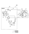
- FIG. 1 is a configuration diagram of an air conditioner 100 according to the first embodiment.
- the air conditioner 100 is a device that performs air conditioning such as heating operation and cooling operation.
- the air conditioner 100 includes an outdoor unit Uo, an indoor unit Ui, and a control unit 30 (see FIG. 3).
- the outdoor unit Uo includes an outdoor heat exchanger 12, an outdoor fan 13, an outdoor expansion valve 14a, a compressor 11, an accumulator 29, and a four-way valve 17.
- the indoor unit Ui includes an indoor heat exchanger 15, an indoor fan 16, and an indoor expansion valve 14b.
- the compressor 11 is a device that compresses a low-temperature low-pressure gas refrigerant and discharges it as a high-temperature high-pressure gas refrigerant. As shown in FIG. 1, the compressor 11 includes a compressor motor 11a as a drive source.
- the four-way valve 17 is a valve that switches the flow path of the refrigerant according to the operation mode of the air conditioner 100.
- the outdoor heat exchanger 12 is a heat exchanger in which heat is exchanged between the refrigerant passing through the heat transfer tube (not shown) and the outside air sent from the outdoor fan 13.
- the outdoor fan 13 is a fan that sends outside air to the outdoor heat exchanger 12.
- the outdoor fan 13 includes an outdoor fan motor 13a as a drive source, and is arranged in the vicinity of the outdoor heat exchanger 12.
- the outdoor expansion valve 14a and the indoor expansion valve 14b are valves that reduce the pressure of the refrigerant condensed by the "condenser" (one of the outdoor heat exchanger 12 and the indoor heat exchanger 15).
- the decompressed refrigerant at least one of the outdoor expansion valve 14a and the indoor expansion valve 14b is guided to the "evaporator" (the other of the outdoor heat exchanger 12 and the indoor heat exchanger 15).
- the indoor heat exchanger 15 is a heat exchange in which heat exchange is performed between the refrigerant flowing through the heat transfer tube g (see FIG. 2) and the indoor air (air in the air conditioning target space) sent from the indoor fan 16. It is a vessel.
- the indoor fan 16 is a fan that sends indoor air to the indoor heat exchanger 15.
- the indoor fan 16 has an indoor fan motor 16c (see FIG. 3) as a drive source, and is arranged in the vicinity of the indoor heat exchanger 15.
- the compressor 11 the outdoor heat exchanger 12 (condenser), the outdoor expansion valve 14a (expansion valve), and the indoor expansion valve 14b (expansion valve).
- the indoor heat exchanger 15 evaporator
- the refrigerant (gas) vaporized by the indoor heat exchanger 15 is introduced into the outdoor unit Uo, circulates through the four-way valve 17, and flows into the accumulator 29.
- the accumulator 29 is a shell-shaped member that separates the refrigerant into gas and liquid.
- the accumulator 29 functions as a buffer tank for storing the refrigerant (liquid) when the liquid refrigerant flows in excessively transiently, thereby preventing the liquid compression in the compressor 11. Therefore, the dryness of the refrigerant increases in the accumulator 29, and the highly dry refrigerant flows into the compressor 11.
- the compressor 11 the indoor heat exchanger 15 (condenser), the indoor expansion valve 14b (expansion valve), and the outdoor expansion valve 14a (expansion valve).
- the outdoor heat exchanger 12 evaporator
- the refrigerant circulates in the refrigeration cycle.
- the refrigerant (gas) compressed by the compressor 11 is introduced into the indoor unit Ui via the four-way valve 17.
- the refrigerant (gas) introduced into the indoor unit Ui flows into the indoor heat exchanger 15 and is cooled and condensed by heat exchange with the indoor air blown by the indoor fan 16. At this time, the refrigerant (gas) condensed in the indoor heat exchanger 15 gives the heat of condensation to the indoor air to heat the indoor air.
- the refrigerant (liquid) condensed by the indoor heat exchanger 15 is introduced into the outdoor unit 10 via the indoor expansion valve 14b.
- the refrigerant (liquid) introduced into the outdoor unit 10 is decompressed by the outdoor expansion valve 14a and flows into the outdoor heat exchanger 12.
- the refrigerant (liquid) that has flowed into the outdoor heat exchanger 12 is vaporized by heat exchange with the outside air blown by the outdoor fan 13, and flows into the accumulator 29 via the four-way valve 17. Then, the refrigerant (gas or gas-liquid two-phase state) whose dryness is increased by the accumulator 29 flows into the compressor 11.
- the outdoor unit Uo has a discharge temperature sensor 28b that measures the temperature (discharge temperature Td) of the refrigerant discharged by the compressor 11, and measures the pressure of the refrigerant (discharge pressure Pd) on the outlet side of the compressor 11.
- the discharge pressure sensor 28d and the suction pressure sensor 28e for measuring the pressure of the refrigerant (suction pressure Ps) on the inlet side of the compressor 11 are provided. Instead of the discharge temperature Td, the temperature of the upper part of the chamber of the compressor 11 may be measured and used. Further, one or a plurality of the above-mentioned sensors may be omitted as appropriate.
- the outdoor unit Uo is provided with an outdoor heat exchanger temperature sensor 28c for measuring the condensation temperature Tc (during cooling operation) or the evaporation temperature Te (during heating operation) of the refrigerant in the outdoor heat exchanger 12, and is provided indoors.
- the machine Ui is provided with an indoor heat exchanger temperature sensor 27c for measuring the evaporation temperature Te (during cooling operation) or the condensation temperature Tc (during heating operation) of the refrigerant in the indoor heat exchanger 15.
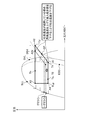
- FIG. 2 is a vertical cross-sectional view of the indoor unit Ui.
- the indoor unit Ui in addition to the indoor heat exchanger 15 and the indoor fan 16 described above, the indoor unit Ui includes a drain pan 18 (also referred to as a dew pan), a housing base 19, and filters 20a and 20b. I have. Further, the indoor unit Ui includes a front panel 21, a left and right wind direction plate 22, and a vertical wind direction plate 23.
- the indoor heat exchanger 15 includes a plurality of fins f and a plurality of heat transfer tubes g penetrating the fins f. From another point of view, the indoor heat exchanger 15 includes a front indoor heat exchanger 15a arranged on the front side of the indoor fan 16 and a rear indoor heat exchanger 15b arranged on the rear side of the indoor fan 16. And have. In the example shown in FIG. 2, the upper end portion of the front indoor heat exchanger 15a and the upper end portion of the rear indoor heat exchanger 15b are connected in an inverted V shape.
- the indoor fan 16 is, for example, a cylindrical cross-flow fan, and is arranged in the vicinity of the indoor heat exchanger 15.
- the indoor fan 16 includes a plurality of fan blades 16a, an annular partition plate 16b on which these fan blades 16a are installed, and an indoor fan motor 16c (see FIG. 3) as a drive source.
- the drain pan 18 receives the condensed water of the indoor heat exchanger 15 and is arranged below the indoor heat exchanger 15.
- the housing base 19 is a housing in which devices such as an indoor heat exchanger 15 and an indoor fan 16 are installed.
- the filters 20a and 20b collect dust from the air toward the indoor heat exchanger 15 as the indoor fan 16 is driven.
- One filter 20a is arranged on the front side of the indoor heat exchanger 15, and the other filter 20b is arranged on the upper side of the indoor heat exchanger 15.
- the front panel 21 is a panel installed so as to cover the filter 20a on the front side, and is rotatable forward with the lower end as an axis.
- the front panel 21 may not rotate.
- the left and right wind direction plate 22 is a plate-shaped member that adjusts the wind direction of the air blown into the room in the left and right direction.
- the left and right wind direction plates 22 are arranged in the blowout air passage h3, and are rotated in the left and right directions by the left and right wind direction plate motors 24 (see FIG. 3).
- the vertical wind direction plate 23 is a plate-shaped member that adjusts the vertical wind direction of the air blown into the room.
- the vertical wind direction plate 23 is arranged near the air outlet h4, and is rotated in the vertical direction by the vertical wind direction plate motor 25 (see FIG. 3).
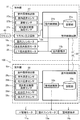
- FIG. 3 is a functional block diagram of the air conditioner 100.
- the indoor unit Ui shown in FIG. 3 includes a remote controller transmission / reception unit 26, an indoor environment detection unit 27, and an indoor control circuit 31 in addition to the above-described configurations.
- the remote control transmission / reception unit 26 exchanges predetermined information with the remote control 40 by infrared communication or the like.
- the indoor environment detection unit 27 includes an indoor temperature sensor 27a, a humidity sensor 27b, and an indoor heat exchanger temperature sensor 27c.
- the indoor temperature sensor 27a is a sensor that detects the temperature in the room (space subject to air conditioning), and is installed on the air suction side of the filters 20a and 20b (see FIG. 2), for example.
- the humidity sensor 27b is a sensor that detects the humidity of the indoor air, and is installed at a predetermined position of the indoor unit Ui.
- the indoor heat exchanger temperature sensor 27c is a sensor that detects the temperature of the indoor heat exchanger 15 (see FIG. 2), and is installed in the indoor heat exchanger 15. The detected values of the indoor temperature sensor 27a, the humidity sensor 27b, and the indoor heat exchanger temperature sensor 27c are output to the indoor control circuit 31.
- the indoor control circuit 31 includes electronic circuits such as a CPU (Central Processing Unit), a ROM (Read Only Memory), a RAM (Random Access Memory), and various interfaces. Then, the program stored in the ROM is read out and expanded in the RAM, and the CPU executes various processes.
- a CPU Central Processing Unit
- ROM Read Only Memory
- RAM Random Access Memory
- the indoor control circuit 31 includes a storage unit 31a and an indoor control unit 31b.
- the storage unit 31a stores data received via the remote controller transmission / reception unit 26, detection values of each sensor, and the like.
- the indoor control unit 31b controls the indoor fan motor 16c, the left and right wind direction plate motor 24, the vertical wind direction plate motor 25, the indoor expansion valve 14b, and the like based on the data stored in the storage unit 31a.
- the outdoor unit Uo includes an outdoor environment detection unit 28 and an outdoor control circuit 32 in addition to those described with reference to FIG.
- the outdoor environment detection unit 28 includes an outdoor temperature sensor 28a, a discharge temperature sensor 28b, an outdoor heat exchanger temperature sensor 28c, a discharge pressure sensor 28d, and a suction pressure sensor 28e.
- the detected value of each sensor including the outdoor temperature sensor 28a is output to the outdoor control circuit 32.
- the outdoor control circuit 32 includes electronic circuits such as a CPU, ROM, RAM, and various interfaces, and is connected to the indoor control circuit 31 via a communication line. As shown in FIG. 3, the outdoor control circuit 32 includes a storage unit 32a and an outdoor control unit 32b.
- the storage unit 32a stores data and the like received from the room control circuit 31.
- the outdoor control unit 32b controls the compressor motor 11a, the outdoor fan motor 13a, the outdoor expansion valve 14a, and the like based on the data stored in the storage unit 32a.
- the indoor control circuit 31 and the outdoor control circuit 32 are collectively referred to as a “control unit 30”.
- FIG. 4 is a flowchart of a process related to freeze cleaning of the indoor heat exchanger 15. Refer to FIGS. 1, 2 and 3 as appropriate. The processing of the control unit 30 regarding the freeze-cleaning of the indoor heat exchanger 15 will be described with reference to FIG.
- step S101 of FIG. 4 the control unit 30 freezes the indoor heat exchanger 15. That is, the control unit 30 causes the indoor heat exchanger 15 to function as an evaporator, frosts the moisture in the air on the indoor heat exchanger 15, and freezes the indoor heat exchanger 15.
- the control unit 30 drives the compressor 11 (see FIG. 1) to increase the opening degree of the outdoor expansion valve 14a (first expansion valve), and the indoor expansion valve 14b (second expansion valve). Controls the opening of the valve). For example, the control unit 30 makes the opening degree of the indoor expansion valve 14b smaller than that during the cooling operation.
- the outdoor expansion valve 14a may be set to an opening degree larger than the opening degree of the indoor expansion valve 14b in order to reduce the flow path loss in the piping.
- the low-pressure refrigerant having a low evaporation temperature flows into the indoor heat exchanger 15, so that the moisture in the air is frosted in the indoor heat exchanger 15, and the frost and ice (reference numeral i shown in FIG. 5) are further formed. Becomes easier to grow.
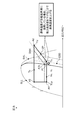
- FIG. 5 is an explanatory diagram showing a state in which the indoor heat exchanger 15 is being thawed.
- the control unit 30 stops devices such as the indoor fan 16 and the compressor 11 (see FIG. 1).
- the frost and ice (reference numeral i shown in FIG. 5) of the indoor heat exchanger 15 are naturally thawed at room temperature, and a large amount of water w flows down to the drain pan 18 along the fin f.
- the dust j adhering to the indoor heat exchanger 15 is washed away.
- control unit 30 may perform a heating operation or a ventilation operation to dry the inside of the indoor unit Ui. As a result, the growth of fungi and other fungi in the indoor unit Ui can be suppressed.
- FIG. 6 is an explanatory diagram showing a state diagram of the refrigerant during the freezing process.
- FIG. 7 is an explanatory diagram showing a problem during the freezing process.
- CP is the compression process
- DSH is the discharge superheat
- EDD is the isothermal diagram (Etc. Dryness diagram)
- II is the isothermal line (Isentropic line).
- ISS is the isothermal line of superheated steam (Isotherms superheated steam)
- ISL is the isotherms of supercooled liquid
- IWS is the isotherm wet steam
- SLL is the saturated liquid.
- the line (Saturated liquid line) and SVL indicate a saturated vapor line (Saturated vapor line).
- the freezing temperature is created by each actuator such as the operating frequency F of the compressor 11 (rotational speed Fr of the compressor 11), the outdoor expansion valve 14a, and the indoor expansion valve 14b.
- the discharge temperature Td of the compressor 11 may overheat or the outlet of the indoor heat exchanger 15 during freezing may overheat.
- the refrigerant (gas) in the state of point A1 is compressed by the compressor 14 (compression step CP).
- the temperature (specific enthalpy) and pressure rise to the state of point A2, which is introduced into the outdoor heat exchanger 12.
- the refrigerant (gas) introduced into the outdoor heat exchanger 12 condenses at substantially equal pressure to a state of point A3 (a state in the liquid or gas-liquid two-phase region), and the indoor expansion valve via the outdoor expansion valve 14a. Introduced in 14b.
- the refrigerant (liquid) introduced into the indoor expansion valve 14b in the state of point A3 is decompressed by the indoor expansion valve 14b to reach the state of point A4, and is vaporized by the indoor heat exchanger 15 to the state of point A1 (gas). Become.
- the refrigerant circulates while transitioning between the states of points A1 to A4. That is, when the refrigerant decompressed by the indoor expansion valve 14b (point A3 ⁇ A4) evaporates at the indoor heat exchanger 15 (point A4 ⁇ A1), the indoor heat exchanger 15 freezes.
- the refrigerant on the outlet side of the outdoor heat exchanger 12 during the freezing process at point 3 is in the gas-liquid two-phase region.
- the freezing power of the indoor heat exchanger 15 is reduced (point A1a in FIG. 7). That is, it becomes difficult to freeze in the downstream region of the indoor heat exchanger 15.
- the discharge temperature Td (discharge refrigerant temperature) of the compressor 11 excessively rises.
- the discharge temperature Td (discharge refrigerant temperature) of the compressor 11 excessively rises.
- the discharge temperature Td (discharge refrigerant temperature) of the compressor 11 may excessively drop.
- the freezing power is less dependent on the amount of refrigerant circulating, and depends on the indoor heat exchanger temperature TE, that is, the freezing temperature.
- the amount of refrigerant circulation is not controlled, but the indoor heat exchanger temperature TE, that is, the freezing temperature, and the dryness of the refrigerant on the inlet side of the compressor 11 (hereinafter referred to as "suction dryness Xs").
- the discharge temperature Td (discharge refrigerant temperature) of the compressor 11 is controlled so as to be a predetermined target, so that the indoor heat exchanger 15 can be appropriately frozen and the reliability of the compressor 11 can be compatible. ..
- FIG. 8 is an explanatory diagram showing a control target in the refrigerant phase diagram during the freezing process according to the first embodiment.
- the liquid pipe temperature and the evaporation temperature Te (indoor heat exchanger temperature TE) are adjusted by controlling the operating frequency (rotational speed control) of the compressor 11.
- the intake refrigerant temperature (suction temperature Ts) and the discharge refrigerant temperature (discharge temperature Td) are adjusted by controlling the opening degree of the indoor expansion valve 14b.
- FIG. 9 is a flowchart showing the details of the process for freezing the indoor heat exchanger 15 according to the first embodiment (S101 in FIG. 4). Refer to FIGS. 1 to 4 as appropriate.
- the control unit 30 makes initial settings.
- Initial setting items include freezing time (time from the start of freezing treatment to the end of freezing treatment), target indoor heat exchanger temperature TL 0 , target discharge temperature Td 0, etc., which are temperatures that are criteria for freezing. ..
- step S12 the control unit 30 controls the four-way valve 17. That is, the control unit 30 controls the four-way valve 17 so that the outdoor heat exchanger 12 functions as a condenser and the indoor heat exchanger 15 functions as an evaporator. If the cooling operation is performed immediately before the "freezing process" (see FIG. 5), the control unit 30 maintains the state of the four-way valve 17 in step S12.
- step S13 the control unit 30 sets the rotation speed of the compressor 11. That is, the control unit 30 sets the rotation speed of the compressor motor 11a based on the outdoor temperature, which is the detection value of the outdoor temperature sensor 28a, and drives the compressor 11.
- the control unit 30 When freezing the indoor heat exchanger 15, the control unit 30 increases the rotation speed of the compressor motor 11a as the outdoor temperature increases. This is because, in order to remove heat from the indoor air in the indoor heat exchanger 15, it is necessary that the outdoor heat exchanger 12 sufficiently dissipates heat accordingly. For example, when the outdoor temperature is relatively high, the control unit 30 increases the temperature and pressure of the refrigerant discharged from the compressor 11 by increasing the rotation speed of the compressor motor 11a. As a result, heat exchange in the outdoor heat exchanger 12 is appropriately performed, and by extension, freezing of the indoor heat exchanger 15 is also appropriately performed.
- the operating frequency (rotational speed) of the compressor 11 may be set by using a map (data table) or a predetermined mathematical formula.
- the rotation speed of the compressor 11 is often controlled based on the temperature of the refrigerant discharged from the compressor 11 (discharge temperature Td) or the like.
- discharge temperature Td discharge temperature
- the indoor heat exchanger temperature since the freezing force depends on the temperature of the indoor heat exchanger 15, in step S30 described later, during the freezing process of the indoor heat exchanger 15, as described above, the indoor heat exchanger temperature. Control based on TE.
- step S14 the control unit 30 adjusts the opening degree of the indoor expansion valve 14b.
- step S14 it is desirable that the opening degree of the indoor expansion valve 14b is smaller than that during normal cooling operation.
- the refrigerant having a lower temperature and lower pressure than that during the normal cooling operation flows into the indoor heat exchanger 15 via the indoor expansion valve 14b. Therefore, the water adhering to the indoor heat exchanger 15 is likely to freeze, and the power consumption required for freezing the indoor heat exchanger 15 can be reduced.
- step S15 the control unit 30 stops the indoor fan 16.
- the control unit 30 may stop the indoor fan 16 or the indoor fan 16 may be stopped. May be driven at a predetermined rotation speed. In either case, the indoor heat exchanger 15 is frozen.
- step S16 the control unit 30 sets the rotation speed of the outdoor fan 33. That is, the control unit 30 sets the rotation speed of the outdoor fan 33 based on the rotation speed of the compressor motor 11a. For example, the higher the rotation speed of the compressor motor 11a, the higher the rotation speed of the outdoor fan 13.
- step S20 the control unit 30 controls the operating frequency F (rotation speed Fr of the compressor 11) of the compressor 11 (see FIG. 10 for details), and in step S30, the control unit 30 expands the room.
- the opening degree V of the valve 14b is controlled (see FIG. 11 for details).
- step S40 the control unit 30 determines whether or not the predetermined freeze end condition is satisfied, and if the freeze end condition is satisfied (S40: Yes), the process is terminated and the freeze end condition is not satisfied (S40). : No), the process returns to step S20. Specifically, assuming that the freezing end condition is a predetermined time after the start of the freezing process, it is determined whether or not the freezing process has reached the freezing time set in step S11. It may be terminated under other freeze termination conditions.
- the control unit 30 has a first predetermined time from the start of the freezing process until the indoor heat exchanger temperature TE falls below the freezing point, or a second predetermined time longer than the first predetermined time.
- the freezing process should be completed. As a result, the freezing process can be terminated without being unnecessarily continued.
- the control unit 30 may control the operating frequency F of the compressor 11 at a preset upper limit operating frequency Fmax or less and a lower limit operating frequency Fmin or more. This is to give priority to the protection of the compressor 11.
- FIG. 10 is a flowchart showing a process of operating frequency control (rotational speed control) of the compressor 11 according to the first embodiment.
- the control unit 30 reads the indoor heat exchanger temperature TL (indoor heat exchanger temperature TE) from the indoor heat exchanger temperature sensor 27c (step S21), sets the indoor heat exchanger temperature TL and the target indoor heat exchanger temperature TL 0 .
- ⁇ TL which is the difference between the two, is calculated (step S22), and it is determined whether or not ⁇ TL is positive (> 0) (step S23). If ⁇ TL is positive (step S23, Yes), the control unit 30 adds a predetermined value ⁇ F to the operating frequency F of the compressor 11 (step S24), and proceeds to step S25. That is, if the indoor heat exchanger 15 is not sufficiently cooled at the current rotation speed of the compressor 11, the rotation speed is increased. On the other hand, if ⁇ TL is not positive (steps S23, No), the process proceeds to step S25.
- step S25 the control unit 30 determines whether or not ⁇ TL is negative ( ⁇ 0). If ⁇ TL is negative (step S25, Yes), the control unit 30 subtracts a predetermined value ⁇ F from the operating frequency F of the compressor 11 (step S26), and proceeds to step S30 (see FIG. 9). That is, since the indoor heat exchanger 15 is sufficiently cold at the current rotation speed of the compressor 11, the rotation speed is reduced. On the other hand, if ⁇ TL is not negative (steps S25 and No), the process proceeds to step S30 (see FIG. 9).
- FIG. 11 is a flowchart showing a process of controlling the opening degree of the indoor expansion valve 14b according to the first embodiment.
- the control unit 30 reads the discharge temperature Td from the discharge temperature sensor 28b (step S31), calculates ⁇ Td which is the difference between the discharge temperature Td and the target discharge temperature Td 0 (step S32), and ⁇ Td is positive (> 0). It is determined whether or not it is (step S33). If ⁇ Td is positive (step S33, Yes), the control unit 30 adds a predetermined value ⁇ V to the opening V of the indoor expansion valve 14b (step S34), and proceeds to step S35. As a result, the control unit 30 lowers the discharge temperature Td. On the other hand, if ⁇ Td is not positive (steps S33, No), the process proceeds to step S35.
- step S35 the control unit 30 determines whether or not ⁇ Td is negative ( ⁇ 0). If ⁇ Td is negative (step S35, Yes), the control unit 30 subtracts a predetermined value ⁇ V from the opening V of the indoor expansion valve 14b (step S36), and proceeds to step S40 (see FIG. 9). As a result, the control unit 30 raises the discharge temperature Td. On the other hand, if ⁇ Td is not negative (steps S35 and No), the process proceeds to step S40 (see FIG. 9).
- step S32 ⁇ Xs is calculated by the equation (1).
- ⁇ Xs Xs-Xs 0 ... (1)
- Xs 0 is the target inhalation dryness.
- the control unit 30 may adjust the opening degree V of the indoor expansion valve 14b according to the positive or negative of ⁇ Xs. That is, when ⁇ Xs is positive, the opening V of the indoor expansion valve 14b may be increased, and when ⁇ Xs is negative, the opening V of the indoor expansion valve 14b may be decreased.
- the control unit 30 determines at least the refrigerant discharge temperature Td in the compressor 11, the refrigerant discharge pressure Pd in the compressor 11, the suction pressure Ps in the compressor 11, and the rotation speed Fr of the compressor 11. ,
- the inhalation dryness Xs may be estimated by the calculation based on.
- FIG. 12 is an explanatory diagram showing an example of a temporal change in the temperature of the indoor heat exchanger 15.
- the target indoor heat exchanger temperature TL 0 has a set width (dead zone). This has a set range because it is affected by chattering and noise when controlled at one point.
- the set width is the difference between the target temperature Td 1 and the target temperature Td 2 .
- the target temperature Td 1 is a value obtained by adding a predetermined value ⁇ TL 0 to the target indoor heat exchanger temperature TL 0
- the target temperature Td 2 is a value obtained by subtracting a predetermined value ⁇ TL 0 from the target indoor heat exchanger temperature TL 0 .
- the horizontal axis of FIG. 12 is the elapsed time from the start of the freezing process.
- the vertical axis of FIG. 12 is the indoor heat exchanger temperature TE.
- the indoor heat exchanger temperature TE rapidly freezes based on the relative humidity of the indoor air (air-conditioned space) and the like.
- the control unit 30 lowers the operating frequency F of the compressor 11 (see time t 21 ).
- the indoor heat exchanger temperature TE rises.
- the control unit 30 increases the operating frequency F of the compressor 11 (see time t 22). After that, when the freezing time is reached, the control unit 30 ends the freezing process and shifts to the next step (for example, drying process).
- the target indoor heat exchanger temperature TL 0 is set in advance, but the present invention is not limited to this.
- the control unit 30 controls the operating frequency of the compressor 11 based on the target temperature of the indoor heat exchanger 15 (target indoor heat exchanger temperature TL 0 ), and also controls the operating frequency of the compressor 11.
- the target temperature of the indoor heat exchanger 15 is changed.
- the control unit 30 raises or lowers the target indoor heat exchanger temperature TL 0 (target freezing temperature), giving priority to the reliability of the compressor 11 and the prevention of overheating at the outlet of the indoor heat exchanger 15. Let me.
- FIG. 13 is an explanatory diagram showing a correction for lowering the discharge temperature Td in the refrigerant phase diagram during the freezing process according to the second embodiment.
- the target discharge temperature Td 0 of the compressor 11 is represented by the equation (2) by the condensation temperature Tc and the target discharge superheat degree Td SH .
- Td 0 Tc + Td SH ... (2)
- Td SH A ⁇ + B ... (3)
- a and B are coefficients ⁇ is a pressure ratio which is a ratio of the discharge pressure Pd to the suction pressure Ps.
- the indoor heat exchanger 15 can be frozen at a surface temperature of less than 0 ° C., so that the freezing temperature is set to ⁇ 5 ° C., that is, the target. Raise the indoor heat exchanger temperature TL 0 from -15 ° C to -5 ° C. As a result, the point A2 can be changed to the point A2d. Therefore, when the discharge temperature Td is excessively raised, the discharge temperature Td can be lowered by raising the evaporation temperature and lowering the suction dryness Xs (less than 1). Therefore, the reliability of the compressor and the reliability of the equipment can be improved by preventing the heat exchange outlet from overheating.
- the control unit 30 controls the suction dryness Xs of the suction refrigerant in order to prevent overheating of the outlet of the indoor heat exchanger 15.
- the target indoor heat exchanger temperature TL 0 target freezing temperature
- the target suction dryness Xs 0 or the target discharge temperature Td 0 is adjusted slightly up or down. I try to bring it closer to the freezing temperature.
- FIG. 14 is an explanatory diagram showing an adjustment for raising the evaporation temperature in the refrigerant phase diagram during the freezing process according to the third embodiment.
- the evaporation temperature Te falls below the target value
- the evaporation temperature Te is raised by lowering the target suction dryness Xs 0 .
- the point A1 can be moved to the point A1b.
- the evaporation temperature Te falls below the target value
- the evaporation temperature Te is raised by lowering the target discharge temperature Td 0 .
- the point A1 can be moved to the point A1b.
- FIG. 15 is an explanatory diagram showing an adjustment for lowering the evaporation temperature in the refrigerant phase diagram during the freezing process according to the third embodiment.
- the evaporation temperature Te when the evaporation temperature Te is higher than the target value, the evaporation temperature is lowered by increasing the target suction dryness Xs 0 . As a result, the point A1 can be moved to the point A1c.
- the evaporation temperature Te is higher than the target value
- the evaporation temperature is lowered by raising the target discharge temperature Td 0 .
- the point A1 can be moved to the point A1c.
- the control unit 30 adjusts the suction dryness Xs by ⁇ 0.05. This makes it possible to bring the evaporation temperature Te of the indoor heat exchanger 15 closer to the target of ⁇ several ° C.
- the target indoor heat exchanger temperature TL 0 target freezing temperature
- the evaporation temperature Te is lower than -15 ° C
- the target suction dryness Xs 0 is lowered to raise the evaporation temperature Te. If the evaporation temperature Te exceeds ⁇ 15 ° C., the target suction dryness Xs 0 is increased and the evaporation temperature Te is decreased.
- the evaporation temperature Te is adjusted by raising or lowering the suction dryness Xs, but the present invention is not limited to this.
- the relationship between the freezing temperature and the suction dryness Xs changes depending on the high / low pressure ratio of the operating pressure. Therefore, the control unit 30 controls the air volume of the outdoor fan 13 to raise or lower the high pressure. It is also possible to change the balance between the freezing temperature and the suction dryness Xs.
- FIG. 16 is an explanatory diagram showing a change in cycle balance depending on the rotation speed of the outdoor fan 13 in the refrigerant phase diagram during the freezing process according to the fourth embodiment.
- the cycle S0 of points A1 ⁇ A2 ⁇ A3 ⁇ A4 ⁇ A1 can be changed to cycle S1 or changed to cycle S2 by adjusting the rotation speed of the outdoor fan 13.
- the evaporation temperature Te can be raised or lowered, and the pressure ratio ⁇ , the suction dryness Xs, and the discharge temperature Td can be corrected.
- the outdoor fan 13 may be controlled based on the pressure ratio ⁇ of the discharge pressure Pd and the suction pressure Ps or the discharge pressure Pd.
- step S20 of FIG. 10 the control of the operating frequency F of the compressor 11 is described based on the indoor heat exchanger temperature TE (target indoor heat exchanger temperature TL 0 ), but the control is not limited thereto.
- the control unit 30 may control the compressor 11 based on the pressure ratio ⁇ , which is the ratio of the discharge pressure Pd to the suction pressure Ps, or the discharge pressure Pd, instead of the indoor heat exchanger temperature TE.
- the indoor heat exchanger can be appropriately frozen and the reliability of the compressor can be ensured.
- the target chamber heat exchanger temperature TL 0 has been described as constant, but it may be lowered stepwise with the passage of time during the freezing process. As a result, the sound generated by the freezing phenomenon during the freezing process can be reduced.
- the present embodiment can also be applied to an air conditioner in which a supercooler is provided between the outdoor heat exchanger 13 and the outdoor expansion valve 14a.
- Each embodiment can be applied to any of a room air conditioner (RAC), a package air conditioner (PAC), and a building multi air conditioner (VRF).
- RAC room air conditioner
- PAC package air conditioner
- VRF building multi air conditioner
- each embodiment is described in detail in order to explain the present invention in an easy-to-understand manner, and is not necessarily limited to the one including all the configurations described. Further, it is possible to add / delete / replace a part of the configuration of each embodiment with another configuration.
- the above-mentioned mechanism and configuration show what is considered necessary for explanation, and do not necessarily show all the mechanisms and configurations in the product.
- Outdoor heat exchanger (condenser / evaporator) 13 Outdoor fan 14a Outdoor expansion valve (expansion valve, first expansion valve) 14b Indoor expansion valve (expansion valve, second expansion valve) 15 Indoor heat exchanger (evaporator / condenser) 16 Indoor fan 17 Four-way valve 18 Drain pan 19 Housing base 27 Indoor environment detector 27a Indoor temperature sensor 27b Humidity sensor 27c Indoor heat exchanger temperature sensor 28 Outdoor environment detector 28a Outdoor temperature sensor 28b Discharge temperature sensor 28c Outdoor heat exchanger temperature Sensor 28d Discharge pressure sensor 28e Suction pressure sensor 30 Control unit 40 Remote control 100 Air conditioner F Compressor operating frequency Fr Compressor rotation speed Fmax Upper limit operating frequency Fmin Lower limit operating frequency Tc Condensation temperature Te Evaporation temperature TE Indoor heat exchanger temperature (Indoor heat exchanger temperature) Td discharge temperature (discharge refrigerant temperature) Td 0 target discharge temperature (target discharge refrigerant temperature) Ts suction temperature (suction refrigerant temperature) TL 0 Target indoor heat exchange
Abstract
This air conditioner comprises: a refrigerant circuit in which a refrigerant circulates sequentially in a refrigeration cycle through a compressor, a condenser, an expansion valve, and an evaporator; and a control unit that controls at least the compressor and the expansion valve. One of the condenser and the evaporator is an outdoor heat exchanger, and the other is an indoor heat exchanger. The control unit causes the indoor heat exchanger to function as the evaporator, and controls the operating frequency of the compressor on the basis of the temperature of the indoor heat exchanger during a freezing treatment of freezing the indoor heat exchanger (step S20), as well as controls the opening of the expansion valve on the basis of the dryness of the refrigerant sucked into the compressor or the temperature of the refrigerant discharged from the compressor (step S30).
Description
本発明は、空気調和機に関する。
The present invention relates to an air conditioner.
空気調和機の室内熱交換器を清潔な状態にする技術として、例えば、特許文献1には、室内熱交換器の着霜・除霜を順次に行って、室内熱交換器の汚れを除去することが記載されている。
As a technique for cleaning the indoor heat exchanger of an air conditioner, for example, in Patent Document 1, frosting and defrosting of the indoor heat exchanger are sequentially performed to remove dirt from the indoor heat exchanger. It is stated that.
特許文献1によれば、除湿運転をする際に、室内熱交換器の親水性プレコートフィンに対して着霜させる場合に、外気温度が高い時には室内熱交換器の温度は比較的高いために、室内熱交換器の温度を低下させるには、外気温度に応じて、室外機の室外送風機の回転速度及び電動膨張弁の開度を制御することが記載されている。すなわち、外気温度が高くなるにつれて、室外機の室外送風機の回転速度を上げ、電動膨張弁の開度を小さくする。これにより、室内熱交換器の温度を低下させて、室内熱交換器を凍結させて親水性プレコートフィンに対して着霜させることができるとしている。
According to Patent Document 1, when the hydrophilic precoat fins of the indoor heat exchanger are frosted during the dehumidifying operation, the temperature of the indoor heat exchanger is relatively high when the outside air temperature is high. In order to lower the temperature of the indoor heat exchanger, it is described that the rotation speed of the outdoor blower of the outdoor unit and the opening degree of the electric expansion valve are controlled according to the outside air temperature. That is, as the outside air temperature rises, the rotation speed of the outdoor blower of the outdoor unit is increased and the opening degree of the electric expansion valve is decreased. As a result, the temperature of the indoor heat exchanger can be lowered, and the indoor heat exchanger can be frozen and frosted on the hydrophilic pre-coated fins.
しかしながら、発明者らは種々の検討を行い、凍結洗浄運転は運転温度条件や、配管長・接続室内台数などシステムの熱容量が異なる多様な施工条件に対応する必要がある。例えば、低い外気温度と高い外気温度における凍結運転時(凍結処理中)の高圧圧力は異なり、目標凍結温度における低圧圧力の組合せによっては圧縮機の吐出温度の過昇や、過降により圧縮機の信頼性を著しく損ねる可能性がある。また、目標凍結温度に到達しても、室内熱交換器の出口において過熱状態に至ると過熱域で熱交換性能が低下し凍結しない可能性があることを見出した。
However, the inventors have conducted various studies, and it is necessary for the freeze-cleaning operation to correspond to various construction conditions such as operating temperature conditions, pipe length, number of connected rooms, and other heat capacities of the system. For example, the high-pressure pressure during freezing operation (during freezing treatment) at a low outside air temperature and a high outside air temperature is different, and depending on the combination of the low-pressure pressure at the target freezing temperature, the discharge temperature of the compressor may be excessively increased or decreased. It can significantly impair reliability. It was also found that even if the target freezing temperature is reached, if the outlet of the indoor heat exchanger reaches a superheated state, the heat exchange performance may deteriorate in the superheated region and the product may not freeze.
本発明は、前記の課題を解決するための発明であって、室内熱交換器を適切に凍結するとともに、圧縮機の信頼性を確保できる空気調和機を提供することを目的とする。
The present invention is an invention for solving the above-mentioned problems, and an object of the present invention is to provide an air conditioner capable of appropriately freezing an indoor heat exchanger and ensuring the reliability of a compressor.
前記目的を達成するため、本発明の空気調和機は、圧縮機、凝縮器、膨張弁、及び蒸発器を順次に介して、冷凍サイクルで冷媒が循環する冷媒回路と、少なくとも圧縮機及び膨張弁を制御する制御部と、を備え、凝縮器及び蒸発器の一方は室外熱交換器であり、他方は室内熱交換器であり、制御部は、室内熱交換器を蒸発器として機能させ、室内熱交換器を凍結させる凍結処理中に、室内熱交換器の温度に基づいて圧縮機の運転周波数の制御を行うとともに、圧縮機の吸入冷媒の乾き度、又は、圧縮機の吐出冷媒温度に基づいて膨張弁の開度の制御を行うことを特徴とする。本発明のその他の態様については、後記する実施形態において説明する。
In order to achieve the above object, the air conditioner of the present invention includes a refrigerant circuit in which the refrigerant circulates in the refrigeration cycle via the compressor, the condenser, the expansion valve, and the evaporator in order, and at least the compressor and the expansion valve. One of the condenser and the evaporator is an outdoor heat exchanger and the other is an indoor heat exchanger, and the control unit makes the indoor heat exchanger function as an evaporator and indoors. During the freezing process to freeze the heat exchanger, the operating frequency of the compressor is controlled based on the temperature of the indoor heat exchanger, and the dryness of the intake refrigerant of the compressor or the discharge refrigerant temperature of the compressor is used. It is characterized in that the opening degree of the expansion valve is controlled. Other aspects of the present invention will be described in embodiments described below.
本発明によれば、室内熱交換器を適切に凍結するとともに、圧縮機の信頼性を確保できる。
According to the present invention, the indoor heat exchanger can be appropriately frozen and the reliability of the compressor can be ensured.
≪第1実施形態≫
<空気調和機の構成>
図1は、第1実施形態に係る空気調和機100の構成図である。空気調和機100は、暖房運転や冷房運転等の空調を行う機器である。図1に示すように、空気調和機100は、室外機Uo、室内機Ui、及び制御部30(図3参照)を含んで構成される。室外機Uoは、室外熱交換器12、室外ファン13、室外膨張弁14a、圧縮機11、アキュムレータ29、及び四方弁17を含んで構成されている。一方、室内機Uiは、室内熱交換器15、室内ファン16、室内膨張弁14bを含んで構成される。 << First Embodiment >>
<Composition of air conditioner>
FIG. 1 is a configuration diagram of anair conditioner 100 according to the first embodiment. The air conditioner 100 is a device that performs air conditioning such as heating operation and cooling operation. As shown in FIG. 1, the air conditioner 100 includes an outdoor unit Uo, an indoor unit Ui, and a control unit 30 (see FIG. 3). The outdoor unit Uo includes an outdoor heat exchanger 12, an outdoor fan 13, an outdoor expansion valve 14a, a compressor 11, an accumulator 29, and a four-way valve 17. On the other hand, the indoor unit Ui includes an indoor heat exchanger 15, an indoor fan 16, and an indoor expansion valve 14b.
<空気調和機の構成>
図1は、第1実施形態に係る空気調和機100の構成図である。空気調和機100は、暖房運転や冷房運転等の空調を行う機器である。図1に示すように、空気調和機100は、室外機Uo、室内機Ui、及び制御部30(図3参照)を含んで構成される。室外機Uoは、室外熱交換器12、室外ファン13、室外膨張弁14a、圧縮機11、アキュムレータ29、及び四方弁17を含んで構成されている。一方、室内機Uiは、室内熱交換器15、室内ファン16、室内膨張弁14bを含んで構成される。 << First Embodiment >>
<Composition of air conditioner>
FIG. 1 is a configuration diagram of an
圧縮機11は、低温低圧のガス冷媒を圧縮し、高温高圧のガス冷媒として吐出する機器である。図1に示すように、圧縮機11は、駆動源である圧縮機モータ11aを備えている。四方弁17は、空気調和機100の運転モードに応じて、冷媒の流路を切り替える弁である。
The compressor 11 is a device that compresses a low-temperature low-pressure gas refrigerant and discharges it as a high-temperature high-pressure gas refrigerant. As shown in FIG. 1, the compressor 11 includes a compressor motor 11a as a drive source. The four-way valve 17 is a valve that switches the flow path of the refrigerant according to the operation mode of the air conditioner 100.
室外熱交換器12は、その伝熱管(図示せず)を通流する冷媒と、室外ファン13から送り込まれる外気と、の間で熱交換が行われる熱交換器である。室外ファン13は、室外熱交換器12に外気を送り込むファンである。室外ファン13は、駆動源である室外ファンモータ13aを備え、室外熱交換器12の付近に配置されている。
The outdoor heat exchanger 12 is a heat exchanger in which heat is exchanged between the refrigerant passing through the heat transfer tube (not shown) and the outside air sent from the outdoor fan 13. The outdoor fan 13 is a fan that sends outside air to the outdoor heat exchanger 12. The outdoor fan 13 includes an outdoor fan motor 13a as a drive source, and is arranged in the vicinity of the outdoor heat exchanger 12.
室外膨張弁14a、室内膨張弁14bは、「凝縮器」(室外熱交換器12及び室内熱交換器15の一方)で凝縮した冷媒を減圧する弁である。なお、室外膨張弁14a及び室内膨張弁14bのうち少なくとも一方で減圧された冷媒は、「蒸発器」(室外熱交換器12及び室内熱交換器15の他方)に導かれる。
The outdoor expansion valve 14a and the indoor expansion valve 14b are valves that reduce the pressure of the refrigerant condensed by the "condenser" (one of the outdoor heat exchanger 12 and the indoor heat exchanger 15). The decompressed refrigerant at least one of the outdoor expansion valve 14a and the indoor expansion valve 14b is guided to the "evaporator" (the other of the outdoor heat exchanger 12 and the indoor heat exchanger 15).
室内熱交換器15は、その伝熱管g(図2参照)を通流する冷媒と、室内ファン16から送り込まれる室内空気(空調対象空間の空気)と、の間で熱交換が行われる熱交換器である。室内ファン16は、室内熱交換器15に室内空気を送り込むファンである。室内ファン16は、駆動源である室内ファンモータ16c(図3参照)を有し、室内熱交換器15の付近に配置されている。
The indoor heat exchanger 15 is a heat exchange in which heat exchange is performed between the refrigerant flowing through the heat transfer tube g (see FIG. 2) and the indoor air (air in the air conditioning target space) sent from the indoor fan 16. It is a vessel. The indoor fan 16 is a fan that sends indoor air to the indoor heat exchanger 15. The indoor fan 16 has an indoor fan motor 16c (see FIG. 3) as a drive source, and is arranged in the vicinity of the indoor heat exchanger 15.
冷房運転時(図1の破線矢印を参照)には、冷媒回路Qにおいて、圧縮機11、室外熱交換器12(凝縮器)、室外膨張弁14a(膨張弁)、室内膨張弁14b(膨張弁)、及び室内熱交換器15(蒸発器)を順次に介して、冷凍サイクルで冷媒が循環する。
During the cooling operation (see the broken line arrow in FIG. 1), in the refrigerant circuit Q, the compressor 11, the outdoor heat exchanger 12 (condenser), the outdoor expansion valve 14a (expansion valve), and the indoor expansion valve 14b (expansion valve). ) And the indoor heat exchanger 15 (evaporator) in sequence, the refrigerant circulates in the refrigeration cycle.
室内熱交換器15で気化した冷媒(気体)は、室外機Uoに導入され、四方弁17を流通してアキュムレータ29に流入する。アキュムレータ29は、冷媒を気液分離する殻状部材である。アキュムレータ29は、過渡的に液冷媒が過剰に流入した際に冷媒(液体)を貯留するバッファタンクとして機能し、これによって圧縮機11での液圧縮が防止される。従って、アキュムレータ29において冷媒の乾き度が高まり、圧縮機11には乾き度の高い冷媒が流入する。
The refrigerant (gas) vaporized by the indoor heat exchanger 15 is introduced into the outdoor unit Uo, circulates through the four-way valve 17, and flows into the accumulator 29. The accumulator 29 is a shell-shaped member that separates the refrigerant into gas and liquid. The accumulator 29 functions as a buffer tank for storing the refrigerant (liquid) when the liquid refrigerant flows in excessively transiently, thereby preventing the liquid compression in the compressor 11. Therefore, the dryness of the refrigerant increases in the accumulator 29, and the highly dry refrigerant flows into the compressor 11.
暖房運転時(図1の実線矢印を参照)には、冷媒回路Qにおいて、圧縮機11、室内熱交換器15(凝縮器)、室内膨張弁14b(膨張弁)、室外膨張弁14a(膨張弁)、及び室外熱交換器12(蒸発器)を順次に介して、冷凍サイクルで冷媒が循環する。
During the heating operation (see the solid line arrow in FIG. 1), in the refrigerant circuit Q, the compressor 11, the indoor heat exchanger 15 (condenser), the indoor expansion valve 14b (expansion valve), and the outdoor expansion valve 14a (expansion valve). ) And the outdoor heat exchanger 12 (evaporator), and the refrigerant circulates in the refrigeration cycle.
圧縮機11で圧縮された冷媒(気体)は、四方弁17を経由して室内機Uiに導入される。室内機Uiに導入された冷媒(気体)は室内熱交換器15に流入し、室内ファン16で送風される室内空気との熱交換で冷却されて凝縮する。このとき、室内熱交換器15で凝縮する冷媒(気体)が凝縮熱を室内空気に与えて室内空気を加熱する。室内熱交換器15で凝縮した冷媒(液体)は室内膨張弁14bを経由して室外機10に導入される。室外機10に導入された冷媒(液体)は、室外膨張弁14aで減圧されて室外熱交換器12に流入する。室外熱交換器12に流入した冷媒(液体)は、室外ファン13で送風される外気との熱交換で気化し、四方弁17を経由してアキュムレータ29に流入する。そして、アキュムレータ29で乾き度が高まった冷媒(気体、又は気液二相状態)が圧縮機11に流入する。
The refrigerant (gas) compressed by the compressor 11 is introduced into the indoor unit Ui via the four-way valve 17. The refrigerant (gas) introduced into the indoor unit Ui flows into the indoor heat exchanger 15 and is cooled and condensed by heat exchange with the indoor air blown by the indoor fan 16. At this time, the refrigerant (gas) condensed in the indoor heat exchanger 15 gives the heat of condensation to the indoor air to heat the indoor air. The refrigerant (liquid) condensed by the indoor heat exchanger 15 is introduced into the outdoor unit 10 via the indoor expansion valve 14b. The refrigerant (liquid) introduced into the outdoor unit 10 is decompressed by the outdoor expansion valve 14a and flows into the outdoor heat exchanger 12. The refrigerant (liquid) that has flowed into the outdoor heat exchanger 12 is vaporized by heat exchange with the outside air blown by the outdoor fan 13, and flows into the accumulator 29 via the four-way valve 17. Then, the refrigerant (gas or gas-liquid two-phase state) whose dryness is increased by the accumulator 29 flows into the compressor 11.
すなわち、圧縮機11、「凝縮器」、室外膨張弁14a、室内膨張弁14b及び「蒸発器」を順次に介して冷媒が循環する冷媒回路Qにおいて、前記した「凝縮器」及び「蒸発器」の一方は室外熱交換器12であり、他方は室内熱交換器15である。
That is, in the refrigerant circuit Q in which the refrigerant circulates sequentially through the compressor 11, the "condenser", the outdoor expansion valve 14a, the indoor expansion valve 14b, and the "evaporator", the above-mentioned "condenser" and "evaporator". One is the outdoor heat exchanger 12 and the other is the indoor heat exchanger 15.
なお、室外機Uoには、圧縮機11で吐出される冷媒の温度(吐出温度Td)を計測する吐出温度センサ28bと、圧縮機11の出口側での冷媒の圧力(吐出圧力Pd)を計測する吐出圧力センサ28dと、圧縮機11の入口側での冷媒の圧力(吸入圧力Ps)を計測する吸入圧力センサ28eと、が備わっている。なお、吐出温度Tdに替えて、圧縮機11のチャンバー上部温度を計測して使用する構成としてもよい。また、前記した各センサのうち一つ又は複数を適宜省略してもよい。
The outdoor unit Uo has a discharge temperature sensor 28b that measures the temperature (discharge temperature Td) of the refrigerant discharged by the compressor 11, and measures the pressure of the refrigerant (discharge pressure Pd) on the outlet side of the compressor 11. The discharge pressure sensor 28d and the suction pressure sensor 28e for measuring the pressure of the refrigerant (suction pressure Ps) on the inlet side of the compressor 11 are provided. Instead of the discharge temperature Td, the temperature of the upper part of the chamber of the compressor 11 may be measured and used. Further, one or a plurality of the above-mentioned sensors may be omitted as appropriate.
また、室外機Uoには、室外熱交換器12での冷媒の凝縮温度Tc(冷房運転時)又は蒸発温度Te(暖房運転時)を計測するための室外熱交換器温度センサ28cが備わり、室内機Uiには、室内熱交換器15での冷媒の蒸発温度Te(冷房運転時)又は凝縮温度Tc(暖房運転時)を計測するための室内熱交換器温度センサ27cが備わっている。
Further, the outdoor unit Uo is provided with an outdoor heat exchanger temperature sensor 28c for measuring the condensation temperature Tc (during cooling operation) or the evaporation temperature Te (during heating operation) of the refrigerant in the outdoor heat exchanger 12, and is provided indoors. The machine Ui is provided with an indoor heat exchanger temperature sensor 27c for measuring the evaporation temperature Te (during cooling operation) or the condensation temperature Tc (during heating operation) of the refrigerant in the indoor heat exchanger 15.
図2は、室内機Uiの縦断面図である。図2に示すように、室内機Uiは、前記した室内熱交換器15や室内ファン16の他に、ドレンパン18(露受皿ともいう)と、筐体ベース19と、フィルタ20a,20bと、を備えている。さらに、室内機Uiは、前面パネル21と、左右風向板22と、上下風向板23と、を備えている。
FIG. 2 is a vertical cross-sectional view of the indoor unit Ui. As shown in FIG. 2, in addition to the indoor heat exchanger 15 and the indoor fan 16 described above, the indoor unit Ui includes a drain pan 18 (also referred to as a dew pan), a housing base 19, and filters 20a and 20b. I have. Further, the indoor unit Ui includes a front panel 21, a left and right wind direction plate 22, and a vertical wind direction plate 23.
室内熱交換器15は、複数のフィンfと、それらのフィンfを貫通する複数の伝熱管gと、を備えている。また、別の観点から説明すると、室内熱交換器15は、室内ファン16の前側に配置される前側室内熱交換器15aと、室内ファン16の後側に配置される後側室内熱交換器15bと、を備えている。図2に示す例では、前側室内熱交換器15aの上端部と、後側室内熱交換器15bの上端部と、が逆V状に接続されている。
The indoor heat exchanger 15 includes a plurality of fins f and a plurality of heat transfer tubes g penetrating the fins f. From another point of view, the indoor heat exchanger 15 includes a front indoor heat exchanger 15a arranged on the front side of the indoor fan 16 and a rear indoor heat exchanger 15b arranged on the rear side of the indoor fan 16. And have. In the example shown in FIG. 2, the upper end portion of the front indoor heat exchanger 15a and the upper end portion of the rear indoor heat exchanger 15b are connected in an inverted V shape.
室内ファン16は、例えば、円筒状のクロスフローファンであり、室内熱交換器15の付近に配置されている。室内ファン16は、複数のファンブレード16aと、これらのファンブレード16aが設置される円環状の仕切板16bと、駆動源である室内ファンモータ16c(図3参照)と、を備えている。
The indoor fan 16 is, for example, a cylindrical cross-flow fan, and is arranged in the vicinity of the indoor heat exchanger 15. The indoor fan 16 includes a plurality of fan blades 16a, an annular partition plate 16b on which these fan blades 16a are installed, and an indoor fan motor 16c (see FIG. 3) as a drive source.
ドレンパン18は、室内熱交換器15の凝縮水を受けるものであり、室内熱交換器15の下側に配置されている。筐体ベース19は、室内熱交換器15や室内ファン16等の機器が設置される筐体である。
The drain pan 18 receives the condensed water of the indoor heat exchanger 15 and is arranged below the indoor heat exchanger 15. The housing base 19 is a housing in which devices such as an indoor heat exchanger 15 and an indoor fan 16 are installed.
フィルタ20a,20bは、室内ファン16の駆動に伴って室内熱交換器15に向かう空気から塵埃を捕集するものである。一方のフィルタ20aは室内熱交換器15の前側に配置され、他方のフィルタ20bは室内熱交換器15の上側に配置されている。
The filters 20a and 20b collect dust from the air toward the indoor heat exchanger 15 as the indoor fan 16 is driven. One filter 20a is arranged on the front side of the indoor heat exchanger 15, and the other filter 20b is arranged on the upper side of the indoor heat exchanger 15.
前面パネル21は、前側のフィルタ20aを覆うように設置されるパネルであり、下端を軸として前側に回動可能になっている。なお、前面パネル21が回動しない構成であってもよい。
The front panel 21 is a panel installed so as to cover the filter 20a on the front side, and is rotatable forward with the lower end as an axis. The front panel 21 may not rotate.
左右風向板22は、室内に吹き出される空気の左右方向の風向きを調整する板状部材である。左右風向板22は、吹出風路h3に配置され、左右風向板用モータ24(図3参照)によって左右方向に回動するようになっている。
The left and right wind direction plate 22 is a plate-shaped member that adjusts the wind direction of the air blown into the room in the left and right direction. The left and right wind direction plates 22 are arranged in the blowout air passage h3, and are rotated in the left and right directions by the left and right wind direction plate motors 24 (see FIG. 3).
上下風向板23は、室内に吹き出される空気の上下方向の風向きを調整する板状部材である。上下風向板23は、空気吹出口h4の付近に配置され、上下風向板用モータ25(図3参照)によって上下方向に回動するようになっている。
The vertical wind direction plate 23 is a plate-shaped member that adjusts the vertical wind direction of the air blown into the room. The vertical wind direction plate 23 is arranged near the air outlet h4, and is rotated in the vertical direction by the vertical wind direction plate motor 25 (see FIG. 3).
空気吸込口h1,h2を介して吸い込まれた空気は、室内熱交換器15の伝熱管gを通流する冷媒と熱交換し、熱交換した空気が吹出風路h3に導かれる。そして、吹出風路h3を通流する空気は、左右風向板22及び上下風向板23によって所定方向に導かれ、さらに、空気吹出口h4を介して室内に吹き出される。
The air sucked through the air suction ports h1 and h2 exchanges heat with the refrigerant flowing through the heat transfer tube g of the indoor heat exchanger 15, and the heat-exchanged air is guided to the blowout air passage h3. Then, the air flowing through the blowout air passage h3 is guided in a predetermined direction by the left and right wind direction plates 22 and the upper and lower wind direction plates 23, and is further blown into the room through the air outlet h4.
なお、空気の流れに伴って空気吸込口h1,h2に向かう塵埃の大部分は、フィルタ20a,20bで捕集される。しかしながら、細かい塵埃がフィルタ20a,20bを通り抜けて室内熱交換器15に付着することがあるため、室内熱交換器15を定期的に洗浄することが望ましい。そこで、本実施形態では、室内熱交換器15で凍結して着霜させた後、室内熱交換器15を解凍して洗浄するようにしている。以下では、室内熱交換器15の着霜・解凍を含む一連の処理を、室内熱交換器15の「凍結洗浄」という。
Most of the dust directed to the air suction ports h1 and h2 along with the air flow is collected by the filters 20a and 20b. However, since fine dust may pass through the filters 20a and 20b and adhere to the indoor heat exchanger 15, it is desirable to clean the indoor heat exchanger 15 regularly. Therefore, in the present embodiment, after freezing and frosting in the indoor heat exchanger 15, the indoor heat exchanger 15 is thawed and washed. Hereinafter, a series of processes including frost formation and thawing of the indoor heat exchanger 15 will be referred to as “freezing and cleaning” of the indoor heat exchanger 15.
図3は、空気調和機100の機能ブロック図である。図3に示す室内機Uiは、前記した各構成の他に、リモコン送受信部26と、室内環境検出部27と、室内制御回路31と、を備えている。リモコン送受信部26は、赤外線通信等によって、リモコン40との間で所定の情報をやり取りする。
FIG. 3 is a functional block diagram of the air conditioner 100. The indoor unit Ui shown in FIG. 3 includes a remote controller transmission / reception unit 26, an indoor environment detection unit 27, and an indoor control circuit 31 in addition to the above-described configurations. The remote control transmission / reception unit 26 exchanges predetermined information with the remote control 40 by infrared communication or the like.
室内環境検出部27は、室内温度センサ27aと、湿度センサ27bと、室内熱交換器温度センサ27cと、を備えている。室内温度センサ27aは、室内(空調対象空間)の温度を検出するセンサであり、例えば、フィルタ20a,20b(図2参照)の空気吸込側に設置されている。湿度センサ27bは、室内空気の湿度を検出するセンサであり、室内機Uiの所定位置に設置されている。
The indoor environment detection unit 27 includes an indoor temperature sensor 27a, a humidity sensor 27b, and an indoor heat exchanger temperature sensor 27c. The indoor temperature sensor 27a is a sensor that detects the temperature in the room (space subject to air conditioning), and is installed on the air suction side of the filters 20a and 20b (see FIG. 2), for example. The humidity sensor 27b is a sensor that detects the humidity of the indoor air, and is installed at a predetermined position of the indoor unit Ui.
室内熱交換器温度センサ27cは、室内熱交換器15(図2参照)の温度を検出するセンサであり、室内熱交換器15に設置されている。室内温度センサ27a、湿度センサ27b、及び室内熱交換器温度センサ27cの検出値は、室内制御回路31に出力される。
The indoor heat exchanger temperature sensor 27c is a sensor that detects the temperature of the indoor heat exchanger 15 (see FIG. 2), and is installed in the indoor heat exchanger 15. The detected values of the indoor temperature sensor 27a, the humidity sensor 27b, and the indoor heat exchanger temperature sensor 27c are output to the indoor control circuit 31.
室内制御回路31は、図示はしないが、CPU(Central Processing Unit)、ROM(Read Only Memory)、RAM(Random Access Memory)、各種インタフェース等の電子回路を含んで構成されている。そして、ROMに記憶されたプログラムを読み出してRAMに展開し、CPUが各種処理を実行するようになっている。
Although not shown, the indoor control circuit 31 includes electronic circuits such as a CPU (Central Processing Unit), a ROM (Read Only Memory), a RAM (Random Access Memory), and various interfaces. Then, the program stored in the ROM is read out and expanded in the RAM, and the CPU executes various processes.
図3に示すように、室内制御回路31は、記憶部31aと、室内制御部31bと、を備えている。記憶部31aには、所定のプログラムの他、リモコン送受信部26を介して受信したデータや、各センサの検出値等が記憶される。室内制御部31bは、記憶部31aに記憶されたデータに基づいて、室内ファンモータ16c、左右風向板用モータ24、上下風向板用モータ25、室内膨張弁14b等を制御する。
As shown in FIG. 3, the indoor control circuit 31 includes a storage unit 31a and an indoor control unit 31b. In addition to the predetermined program, the storage unit 31a stores data received via the remote controller transmission / reception unit 26, detection values of each sensor, and the like. The indoor control unit 31b controls the indoor fan motor 16c, the left and right wind direction plate motor 24, the vertical wind direction plate motor 25, the indoor expansion valve 14b, and the like based on the data stored in the storage unit 31a.
室外機Uoは、図1で説明した他に、室外環境検出部28と、室外制御回路32と、を備えている。室外環境検出部28は、室外温度センサ28aと、吐出温度センサ28bと、室外熱交換器温度センサ28cと、吐出圧力センサ28dと、吸入圧力センサ28eと、を備えている。室外温度センサ28aを含む各センサの検出値は、室外制御回路32に出力される。
The outdoor unit Uo includes an outdoor environment detection unit 28 and an outdoor control circuit 32 in addition to those described with reference to FIG. The outdoor environment detection unit 28 includes an outdoor temperature sensor 28a, a discharge temperature sensor 28b, an outdoor heat exchanger temperature sensor 28c, a discharge pressure sensor 28d, and a suction pressure sensor 28e. The detected value of each sensor including the outdoor temperature sensor 28a is output to the outdoor control circuit 32.
室外制御回路32は、図示はしないが、CPU、ROM、RAM、各種インタフェース等の電子回路を含んで構成され、通信線を介して室内制御回路31に接続されている。図3に示すように、室外制御回路32は、記憶部32aと、室外制御部32bと、を備えている。
Although not shown, the outdoor control circuit 32 includes electronic circuits such as a CPU, ROM, RAM, and various interfaces, and is connected to the indoor control circuit 31 via a communication line. As shown in FIG. 3, the outdoor control circuit 32 includes a storage unit 32a and an outdoor control unit 32b.
記憶部32aには、所定のプログラムの他、室内制御回路31から受信したデータ等が記憶される。室外制御部32bは、記憶部32aに記憶されたデータに基づいて、圧縮機モータ11a、室外ファンモータ13a、室外膨張弁14a等を制御する。以下では、室内制御回路31及び室外制御回路32を一括して「制御部30」という。
In addition to the predetermined program, the storage unit 32a stores data and the like received from the room control circuit 31. The outdoor control unit 32b controls the compressor motor 11a, the outdoor fan motor 13a, the outdoor expansion valve 14a, and the like based on the data stored in the storage unit 32a. Hereinafter, the indoor control circuit 31 and the outdoor control circuit 32 are collectively referred to as a “control unit 30”.
次に、室内熱交換器15の凍結洗浄に関する制御部30の処理について、図4を用いて説明する。
Next, the process of the control unit 30 related to freeze cleaning of the indoor heat exchanger 15 will be described with reference to FIG.
<制御部の処理>
図4は、室内熱交換器15の凍結洗浄に関する処理のフローチャートである。適宜、図1、図2、図3を参照する。室内熱交換器15の凍結洗浄に関する制御部30の処理について、図4を用いて説明する。 <Processing of control unit>
FIG. 4 is a flowchart of a process related to freeze cleaning of theindoor heat exchanger 15. Refer to FIGS. 1, 2 and 3 as appropriate. The processing of the control unit 30 regarding the freeze-cleaning of the indoor heat exchanger 15 will be described with reference to FIG.
図4は、室内熱交換器15の凍結洗浄に関する処理のフローチャートである。適宜、図1、図2、図3を参照する。室内熱交換器15の凍結洗浄に関する制御部30の処理について、図4を用いて説明する。 <Processing of control unit>
FIG. 4 is a flowchart of a process related to freeze cleaning of the
図4のステップS101において制御部30は、凍結処理をし、室内熱交換器15を凍結させる。すなわち、制御部30は、室内熱交換器15を蒸発器として機能させ、空気中の水分を室内熱交換器15に着霜させて、室内熱交換器15を凍結させる。
In step S101 of FIG. 4, the control unit 30 freezes the indoor heat exchanger 15. That is, the control unit 30 causes the indoor heat exchanger 15 to function as an evaporator, frosts the moisture in the air on the indoor heat exchanger 15, and freezes the indoor heat exchanger 15.
ステップS101についてさらに詳しく説明すると、制御部30は、圧縮機11(図1参照)を駆動し、室外膨張弁14a(第1膨張弁)の開度を大きくし、室内膨張弁14b(第2膨張弁)の開度の制御を行う。例えば、制御部30は、室内膨張弁14bの開度を冷房運転時よりも小さくする。なお、室外膨張弁14aは、配管での流路損失を少なくするため、室内膨張弁14bの開度よりも大きい開度に設定するとよい。
To explain step S101 in more detail, the control unit 30 drives the compressor 11 (see FIG. 1) to increase the opening degree of the outdoor expansion valve 14a (first expansion valve), and the indoor expansion valve 14b (second expansion valve). Controls the opening of the valve). For example, the control unit 30 makes the opening degree of the indoor expansion valve 14b smaller than that during the cooling operation. The outdoor expansion valve 14a may be set to an opening degree larger than the opening degree of the indoor expansion valve 14b in order to reduce the flow path loss in the piping.
これによって、低圧で蒸発温度の低い冷媒が室内熱交換器15に流入するため、空気中の水分が室内熱交換器15で着霜し、さらに、その霜や氷(図5に示す符号i)が成長しやすくなる。
As a result, the low-pressure refrigerant having a low evaporation temperature flows into the indoor heat exchanger 15, so that the moisture in the air is frosted in the indoor heat exchanger 15, and the frost and ice (reference numeral i shown in FIG. 5) are further formed. Becomes easier to grow.
次に、ステップS102において制御部30は、室内熱交換器15を解凍する。
図5は、室内熱交換器15の解凍中の状態を示す説明図である。制御部30は、室内熱交換器15の凍結後、例えば、室内ファン16や圧縮機11(図1参照)等の機器を停止状態にする。これによって、室内熱交換器15の霜や氷(図5に示す符号i)が室温で自然解凍され、多量の水wが、フィンfを伝ってドレンパン18に流れ落ちる。これによって、室内熱交換器15に付着した塵埃jが洗い流される。 Next, in step S102, thecontrol unit 30 defrosts the indoor heat exchanger 15.
FIG. 5 is an explanatory diagram showing a state in which theindoor heat exchanger 15 is being thawed. After the indoor heat exchanger 15 is frozen, the control unit 30 stops devices such as the indoor fan 16 and the compressor 11 (see FIG. 1). As a result, the frost and ice (reference numeral i shown in FIG. 5) of the indoor heat exchanger 15 are naturally thawed at room temperature, and a large amount of water w flows down to the drain pan 18 along the fin f. As a result, the dust j adhering to the indoor heat exchanger 15 is washed away.
図5は、室内熱交換器15の解凍中の状態を示す説明図である。制御部30は、室内熱交換器15の凍結後、例えば、室内ファン16や圧縮機11(図1参照)等の機器を停止状態にする。これによって、室内熱交換器15の霜や氷(図5に示す符号i)が室温で自然解凍され、多量の水wが、フィンfを伝ってドレンパン18に流れ落ちる。これによって、室内熱交換器15に付着した塵埃jが洗い流される。 Next, in step S102, the
FIG. 5 is an explanatory diagram showing a state in which the
なお、室内熱交換器15の凍結・解凍(図4のS101,S102)の後、制御部30が暖房運転又は送風運転を行うことで、室内機Uiの内部を乾燥させてもよい。これによって、室内機Uiにおけるカビ等の菌の繁殖を抑制できる。
After freezing and thawing the indoor heat exchanger 15 (S101 and S102 in FIG. 4), the control unit 30 may perform a heating operation or a ventilation operation to dry the inside of the indoor unit Ui. As a result, the growth of fungi and other fungi in the indoor unit Ui can be suppressed.
図6は、凍結処理中の冷媒状態図を示す説明図である。図7は、凍結処理中の課題を示す説明図である。図6中、CPは、圧縮工程(Compression process)、DSHは、吐出過熱度(Discharge superheat)、EDDは、等乾き度線図(Etc. dryness diagram)、IIは、等エントロピー線(Isentropic line)、ISSは、過熱蒸気の等温線(Isotherms superheated steam)、ISLは、過冷却液の等温線(Isotherms of supercooled liquid)、IWSは、湿り蒸気の等温線(Isotherm wet steam)、SLLは、飽和液線(Saturated liquid line)、SVLは、飽和蒸気線(Saturated vapor line)を示す。
FIG. 6 is an explanatory diagram showing a state diagram of the refrigerant during the freezing process. FIG. 7 is an explanatory diagram showing a problem during the freezing process. In FIG. 6, CP is the compression process, DSH is the discharge superheat, EDD is the isothermal diagram (Etc. Dryness diagram), and II is the isothermal line (Isentropic line). , ISS is the isothermal line of superheated steam (Isotherms superheated steam), ISL is the isotherms of supercooled liquid, IWS is the isotherm wet steam, and SLL is the saturated liquid. The line (Saturated liquid line) and SVL indicate a saturated vapor line (Saturated vapor line).
従来、凍結処理中における凍結温度の制御では、圧縮機11の運転周波数F(圧縮機11の回転速度Fr)や室外膨張弁14a、室内膨張弁14bなど各々のアクチュエータにて凍結温度を作ることは可能となるが、運転条件(温度条件や施工条件)により、圧縮機11の吐出温度Tdが過昇したり凍結中の室内熱交換器15の出口に過熱が生じたりする可能性がある。
Conventionally, in the control of the freezing temperature during the freezing process, the freezing temperature is created by each actuator such as the operating frequency F of the compressor 11 (rotational speed Fr of the compressor 11), the outdoor expansion valve 14a, and the indoor expansion valve 14b. However, depending on the operating conditions (temperature conditions and construction conditions), the discharge temperature Td of the compressor 11 may overheat or the outlet of the indoor heat exchanger 15 during freezing may overheat.
図6及び図7で説明すると、例えば、空気調和機100(図1参照)が凍結処理されるとき、点A1の状態にある冷媒(気体)は、圧縮機14で圧縮されて(圧縮工程CP)温度(比エンタルピ)と圧力が上昇して点A2の状態になり、室外熱交換器12に導入される。室外熱交換器12に導入された冷媒(気体)は、ほぼ等圧で凝縮して点A3の状態(液体又は気液2相域の状態)になり、室外膨張弁14aを介して室内膨張弁14bに導入される。点A3の状態で室内膨張弁14bに導入された冷媒(液体)は室内膨張弁14bで減圧されて点A4の状態になり、室内熱交換器15で気化して点A1の状態(気体)になる。このように、凍結処理する空気調和機100では、冷媒が点A1~A4の状態を遷移しながら循環する。つまり、室内膨張弁14bで減圧(点A3→A4)された冷媒が室内熱交換器15で蒸発(点A4→A1)するときに、室内熱交換器15が凍結する。なお、点3の凍結処理中の室外熱交換器12の出口側の冷媒は気液2相域である。
Explaining with reference to FIGS. 6 and 7, for example, when the air conditioner 100 (see FIG. 1) is frozen, the refrigerant (gas) in the state of point A1 is compressed by the compressor 14 (compression step CP). ) The temperature (specific enthalpy) and pressure rise to the state of point A2, which is introduced into the outdoor heat exchanger 12. The refrigerant (gas) introduced into the outdoor heat exchanger 12 condenses at substantially equal pressure to a state of point A3 (a state in the liquid or gas-liquid two-phase region), and the indoor expansion valve via the outdoor expansion valve 14a. Introduced in 14b. The refrigerant (liquid) introduced into the indoor expansion valve 14b in the state of point A3 is decompressed by the indoor expansion valve 14b to reach the state of point A4, and is vaporized by the indoor heat exchanger 15 to the state of point A1 (gas). Become. In this way, in the air conditioner 100 to be frozen, the refrigerant circulates while transitioning between the states of points A1 to A4. That is, when the refrigerant decompressed by the indoor expansion valve 14b (point A3 → A4) evaporates at the indoor heat exchanger 15 (point A4 → A1), the indoor heat exchanger 15 freezes. The refrigerant on the outlet side of the outdoor heat exchanger 12 during the freezing process at point 3 is in the gas-liquid two-phase region.
このとき、室内熱交換器15の出口の冷媒に過熱が付くと室内熱交換器15の凍結力が低下する(図7の点A1a)。つまり、室内熱交換器15の下流域では凍結しにくくなる。また、図7の点A2aで示すように、圧縮機11の吐出温度Td(吐出冷媒温度)が過昇する。また、図7の点A2bで示すように、圧縮機11の吐出温度Td(吐出冷媒温度)が過昇する。あるいは、図7の点A2cで示すように、圧縮機11の吐出温度Td(吐出冷媒温度)が過降することもある。
At this time, if the refrigerant at the outlet of the indoor heat exchanger 15 is overheated, the freezing power of the indoor heat exchanger 15 is reduced (point A1a in FIG. 7). That is, it becomes difficult to freeze in the downstream region of the indoor heat exchanger 15. Further, as shown by the point A2a in FIG. 7, the discharge temperature Td (discharge refrigerant temperature) of the compressor 11 excessively rises. Further, as shown by the point A2b in FIG. 7, the discharge temperature Td (discharge refrigerant temperature) of the compressor 11 excessively rises. Alternatively, as shown by the point A2c in FIG. 7, the discharge temperature Td (discharge refrigerant temperature) of the compressor 11 may excessively drop.
また、凍結処理時は室内に冷風が吹き込まないように、室内ファン16の風量を抑制又は停止により実施するため、空気側の熱抵抗が大きく伝熱管g(図2参照)の内部の熱抵抗が非常に小さい関係となる。従って、凍結力は冷媒循環量による依存は低く、室内熱交換器温度TEつまり凍結温度に依存する。
Further, during the freezing process, the air volume of the indoor fan 16 is suppressed or stopped so that cold air does not blow into the room. Therefore, the thermal resistance on the air side is large and the thermal resistance inside the heat transfer tube g (see FIG. 2) increases. It's a very small relationship. Therefore, the freezing power is less dependent on the amount of refrigerant circulating, and depends on the indoor heat exchanger temperature TE, that is, the freezing temperature.
そのため、本実施形態では、冷媒循環量を制御するのではなく、室内熱交換器温度TEつまり凍結温度と、圧縮機11の入口側における冷媒の乾き度(以下、「吸入乾き度Xs」と称する)又は圧縮機11の吐出温度Td(吐出冷媒温度)が所定の目標となるよう制御することで、室内熱交換器15を適切に凍結するとともに、圧縮機11の信頼性の両立を可能とする。
Therefore, in the present embodiment, the amount of refrigerant circulation is not controlled, but the indoor heat exchanger temperature TE, that is, the freezing temperature, and the dryness of the refrigerant on the inlet side of the compressor 11 (hereinafter referred to as "suction dryness Xs"). ) Or the discharge temperature Td (discharge refrigerant temperature) of the compressor 11 is controlled so as to be a predetermined target, so that the indoor heat exchanger 15 can be appropriately frozen and the reliability of the compressor 11 can be compatible. ..
図8は、本実施形態1に係る凍結処理中の冷媒状態図における制御対象を示す説明図である。本実施形態では、圧縮機11の運転周波数制御(回転速度制御)により、液管温度、蒸発温度Te(室内熱交換器温度TE)を調整する。さらに、本実施形態では、室内膨張弁14bの開度制御により、吸入冷媒温度(吸入温度Ts)、吐出冷媒温度(吐出温度Td)を調整する。
FIG. 8 is an explanatory diagram showing a control target in the refrigerant phase diagram during the freezing process according to the first embodiment. In the present embodiment, the liquid pipe temperature and the evaporation temperature Te (indoor heat exchanger temperature TE) are adjusted by controlling the operating frequency (rotational speed control) of the compressor 11. Further, in the present embodiment, the intake refrigerant temperature (suction temperature Ts) and the discharge refrigerant temperature (discharge temperature Td) are adjusted by controlling the opening degree of the indoor expansion valve 14b.
図9は、第1実施形態に係る室内熱交換器15を凍結させるための処理(図4のS101)の詳細を示すフローチャートである。適宜、図1~図4を参照する。ステップS11において制御部30は、初期設定をする。初期設定項目として、凍結時間(凍結処理開始後からの凍結処理終了までの時間)の他、凍結の判定基準となる温度である目標室内熱交換器温度TL0、目標吐出温度Td0等がある。
FIG. 9 is a flowchart showing the details of the process for freezing the indoor heat exchanger 15 according to the first embodiment (S101 in FIG. 4). Refer to FIGS. 1 to 4 as appropriate. In step S11, the control unit 30 makes initial settings. Initial setting items include freezing time (time from the start of freezing treatment to the end of freezing treatment), target indoor heat exchanger temperature TL 0 , target discharge temperature Td 0, etc., which are temperatures that are criteria for freezing. ..
ステップS12において制御部30は、四方弁17を制御する。すなわち、制御部30は、室外熱交換器12を凝縮器として機能させ、室内熱交換器15を蒸発器として機能させるように四方弁17を制御する。なお、「凍結処理」(図5参照)を行う直前に冷房運転を行っていた場合、制御部30は、ステップS12において四方弁17の状態を維持する。
In step S12, the control unit 30 controls the four-way valve 17. That is, the control unit 30 controls the four-way valve 17 so that the outdoor heat exchanger 12 functions as a condenser and the indoor heat exchanger 15 functions as an evaporator. If the cooling operation is performed immediately before the "freezing process" (see FIG. 5), the control unit 30 maintains the state of the four-way valve 17 in step S12.
次に、ステップS13において制御部30は、圧縮機11の回転速度を設定する。すなわち、制御部30は、室外温度センサ28aの検出値である室外温度に基づいて、圧縮機モータ11aの回転速度を設定し、圧縮機11を駆動する。
Next, in step S13, the control unit 30 sets the rotation speed of the compressor 11. That is, the control unit 30 sets the rotation speed of the compressor motor 11a based on the outdoor temperature, which is the detection value of the outdoor temperature sensor 28a, and drives the compressor 11.
室内熱交換器15を凍結させる際、制御部30は、室外温度が高いほど、圧縮機モータ11aの回転速度を大きくする。室内熱交換器15において室内空気から熱を奪うには、それに対応して、室外熱交換器12での放熱が充分に行われることを要するからである。例えば、室外温度が比較的高い場合、制御部30は、圧縮機モータ11aの回転速度を大きくすることで、圧縮機11から吐出される冷媒の温度・圧力を高くする。これによって、室外熱交換器12での熱交換が適切に行われ、ひいては、室内熱交換器15の凍結も適切に行われる。なお、圧縮機11の運転周波数(回転速度)の設定は、マップ(データテーブル)、所定の数式を用いるとよい。
When freezing the indoor heat exchanger 15, the control unit 30 increases the rotation speed of the compressor motor 11a as the outdoor temperature increases. This is because, in order to remove heat from the indoor air in the indoor heat exchanger 15, it is necessary that the outdoor heat exchanger 12 sufficiently dissipates heat accordingly. For example, when the outdoor temperature is relatively high, the control unit 30 increases the temperature and pressure of the refrigerant discharged from the compressor 11 by increasing the rotation speed of the compressor motor 11a. As a result, heat exchange in the outdoor heat exchanger 12 is appropriately performed, and by extension, freezing of the indoor heat exchanger 15 is also appropriately performed. The operating frequency (rotational speed) of the compressor 11 may be set by using a map (data table) or a predetermined mathematical formula.
ちなみに、通常の空調運転(冷房運転や暖房運転)では、圧縮機11から吐出される冷媒の温度(吐出温度Td)等に基づいて、圧縮機11の回転速度が制御されることが多い。一方、本実施形態では、凍結力が室内熱交換器15の温度に依存するため、後記するステップS30において、室内熱交換器15を凍結処理中には、前記したように、室内熱交換器温度TEに基づいて制御する。
By the way, in normal air conditioning operation (cooling operation or heating operation), the rotation speed of the compressor 11 is often controlled based on the temperature of the refrigerant discharged from the compressor 11 (discharge temperature Td) or the like. On the other hand, in the present embodiment, since the freezing force depends on the temperature of the indoor heat exchanger 15, in step S30 described later, during the freezing process of the indoor heat exchanger 15, as described above, the indoor heat exchanger temperature. Control based on TE.
ステップS14において制御部30は、室内膨張弁14bの開度を調整する。なお、ステップS14では、通常の冷房運転時よりも室内膨張弁14bの開度を小さくすることが望ましい。これによって、通常の冷房運転時よりも低温低圧の冷媒が、室内膨張弁14bを介して室内熱交換器15に流入する。従って、室内熱交換器15に付着した水が凍結しやすくなり、また、室内熱交換器15の凍結に要する消費電力量を低減できる。
In step S14, the control unit 30 adjusts the opening degree of the indoor expansion valve 14b. In step S14, it is desirable that the opening degree of the indoor expansion valve 14b is smaller than that during normal cooling operation. As a result, the refrigerant having a lower temperature and lower pressure than that during the normal cooling operation flows into the indoor heat exchanger 15 via the indoor expansion valve 14b. Therefore, the water adhering to the indoor heat exchanger 15 is likely to freeze, and the power consumption required for freezing the indoor heat exchanger 15 can be reduced.
ステップS15において制御部30は、室内ファン16を停止する。なお、室内熱交換器15を凍結させているとき(つまり、所定の凍結時間が経過するまでの間)、制御部30は、室内ファン16を停止状態にしてもよいし、また、室内ファン16を所定の回転速度で駆動してもよい。いずれの場合でも、室内熱交換器15の凍結が進むからである。
In step S15, the control unit 30 stops the indoor fan 16. When the indoor heat exchanger 15 is frozen (that is, until a predetermined freezing time elapses), the control unit 30 may stop the indoor fan 16 or the indoor fan 16 may be stopped. May be driven at a predetermined rotation speed. In either case, the indoor heat exchanger 15 is frozen.
ステップS16において制御部30は、室外ファン33の回転速度を設定する。すなわち、制御部30は、圧縮機モータ11aの回転速度に基づいて、室外ファン33の回転速度を設定する。例えば、圧縮機モータ11aの回転速度が大きいほど、室外ファン13の回転速度を大きくする。
In step S16, the control unit 30 sets the rotation speed of the outdoor fan 33. That is, the control unit 30 sets the rotation speed of the outdoor fan 33 based on the rotation speed of the compressor motor 11a. For example, the higher the rotation speed of the compressor motor 11a, the higher the rotation speed of the outdoor fan 13.
次に、ステップS20において制御部30は、圧縮機11の運転周波数F(圧縮機11の回転速度Fr)の制御を行う(詳細は図10参照)とともに、ステップS30において制御部30は、室内膨張弁14bの開度Vの制御を行う(詳細は図11参照)。
Next, in step S20, the control unit 30 controls the operating frequency F (rotation speed Fr of the compressor 11) of the compressor 11 (see FIG. 10 for details), and in step S30, the control unit 30 expands the room. The opening degree V of the valve 14b is controlled (see FIG. 11 for details).
そして、ステップS40において制御部30は、所定の凍結終了条件を満たすか否かを判定し、凍結終了条件を満たす場合(S40:Yes)、処理を終了し、凍結終了条件を満たさない場合(S40:No)、ステップS20に戻る。具体的には、凍結終了条件として凍結処理を開始してからの所定時間とすると、凍結処理が、ステップS11で設定した凍結時間に達したか否かで判定する。なお、他の凍結終了条件で終了してもよい。
Then, in step S40, the control unit 30 determines whether or not the predetermined freeze end condition is satisfied, and if the freeze end condition is satisfied (S40: Yes), the process is terminated and the freeze end condition is not satisfied (S40). : No), the process returns to step S20. Specifically, assuming that the freezing end condition is a predetermined time after the start of the freezing process, it is determined whether or not the freezing process has reached the freezing time set in step S11. It may be terminated under other freeze termination conditions.
他の凍結終了条件としては、例えば、制御部30は、凍結処理を開始してから室内熱交換器温度TEが氷点下になるまでの第1所定時間、又は、第1所定時間より長い第2所定時間が凍結処理を開始してから経過した場合、凍結処理を終了するとよい。これによって、無駄に凍結処理を継続しないで終了することができる。
As another freezing end condition, for example, the control unit 30 has a first predetermined time from the start of the freezing process until the indoor heat exchanger temperature TE falls below the freezing point, or a second predetermined time longer than the first predetermined time. When the time has passed since the start of the freezing process, the freezing process should be completed. As a result, the freezing process can be terminated without being unnecessarily continued.
凍結処理中に、室内熱交換器温度TEと、圧縮機11の吐出温度Td又は圧縮機11の吸入乾き度Xsを両立させようとすると、運転状況によっては圧縮機11の信頼性が低下する場合がある。このため、制御部30は、予め設定された上限運転周波数Fmax以下、かつ、下限運転周波数Fmin以上で、圧縮機11の運転周波数Fの制御を行うとよい。これは、圧縮機11の保護を優先させるためである。
If the indoor heat exchanger temperature TE and the discharge temperature Td of the compressor 11 or the suction dryness Xs of the compressor 11 are to be compatible with each other during the freezing process, the reliability of the compressor 11 may decrease depending on the operating conditions. There is. Therefore, the control unit 30 may control the operating frequency F of the compressor 11 at a preset upper limit operating frequency Fmax or less and a lower limit operating frequency Fmin or more. This is to give priority to the protection of the compressor 11.
図10は、第1実施形態に係る圧縮機11の運転周波数制御(回転速度制御)の処理を示すフローチャートである。制御部30は、室内熱交換器温度センサ27cから室内熱交換器温度TL(室内熱交換器温度TE)を読込み(ステップS21)、室内熱交換器温度TLと目標室内熱交換器温度TL0との差であるΔTLを算出し(ステップS22)、ΔTLが正(>0)であるか否かを判定する(ステップS23)。制御部30は、ΔTLが正であれば(ステップS23,Yes)、圧縮機11の運転周波数Fに所定値ΔFを加算し(ステップS24)、ステップS25に進む。つまり、圧縮機11の現状の回転速度では室内熱交換器15が十分に冷えていない場合、回転速度を増加させる。一方、ΔTLが正でなければ(ステップS23,No)、ステップS25に進む。
FIG. 10 is a flowchart showing a process of operating frequency control (rotational speed control) of the compressor 11 according to the first embodiment. The control unit 30 reads the indoor heat exchanger temperature TL (indoor heat exchanger temperature TE) from the indoor heat exchanger temperature sensor 27c (step S21), sets the indoor heat exchanger temperature TL and the target indoor heat exchanger temperature TL 0 . ΔTL, which is the difference between the two, is calculated (step S22), and it is determined whether or not ΔTL is positive (> 0) (step S23). If ΔTL is positive (step S23, Yes), the control unit 30 adds a predetermined value ΔF to the operating frequency F of the compressor 11 (step S24), and proceeds to step S25. That is, if the indoor heat exchanger 15 is not sufficiently cooled at the current rotation speed of the compressor 11, the rotation speed is increased. On the other hand, if ΔTL is not positive (steps S23, No), the process proceeds to step S25.
ステップS25において制御部30は、ΔTLが負(<0)であるか否かを判定する。制御部30は、ΔTLが負であれば(ステップS25,Yes)、圧縮機11の運転周波数Fに所定値ΔFを減算し(ステップS26)、ステップS30(図9参照)に進む。つまり、圧縮機11の現状の回転速度では室内熱交換器15が十分に冷えすぎているから、回転速度を減少させる。一方、ΔTLが負でなければ(ステップS25,No)、ステップS30(図9参照)に進む。
In step S25, the control unit 30 determines whether or not ΔTL is negative (<0). If ΔTL is negative (step S25, Yes), the control unit 30 subtracts a predetermined value ΔF from the operating frequency F of the compressor 11 (step S26), and proceeds to step S30 (see FIG. 9). That is, since the indoor heat exchanger 15 is sufficiently cold at the current rotation speed of the compressor 11, the rotation speed is reduced. On the other hand, if ΔTL is not negative (steps S25 and No), the process proceeds to step S30 (see FIG. 9).
図11は、第1実施形態に係る室内膨張弁14bの開度制御の処理を示すフローチャートである。制御部30は、吐出温度センサ28bから吐出温度Tdを読込み(ステップS31)、吐出温度Tdと目標吐出温度Td0との差であるΔTdを算出し(ステップS32)、ΔTdが正(>0)であるか否かを判定する(ステップS33)。制御部30は、ΔTdが正であれば(ステップS33,Yes)、室内膨張弁14bの開度Vに、所定値ΔVを加算し(ステップS34)、ステップS35に進む。これによって、制御部30は、吐出温度Tdを下げるようにする。一方、ΔTdが正でなければ(ステップS33,No)、ステップS35に進む。
FIG. 11 is a flowchart showing a process of controlling the opening degree of the indoor expansion valve 14b according to the first embodiment. The control unit 30 reads the discharge temperature Td from the discharge temperature sensor 28b (step S31), calculates ΔTd which is the difference between the discharge temperature Td and the target discharge temperature Td 0 (step S32), and ΔTd is positive (> 0). It is determined whether or not it is (step S33). If ΔTd is positive (step S33, Yes), the control unit 30 adds a predetermined value ΔV to the opening V of the indoor expansion valve 14b (step S34), and proceeds to step S35. As a result, the control unit 30 lowers the discharge temperature Td. On the other hand, if ΔTd is not positive (steps S33, No), the process proceeds to step S35.
ステップS35において制御部30は、ΔTdが負(<0)であるか否かを判定する。制御部30は、ΔTdが負であれば(ステップS35,Yes)、室内膨張弁14bの開度Vに所定値ΔVを減算し(ステップS36)、ステップS40(図9参照)に進む。これによって、制御部30は、吐出温度Tdを上げるようにする。一方、ΔTdが負でなければ(ステップS35,No)、ステップS40(図9参照)に進む。
In step S35, the control unit 30 determines whether or not ΔTd is negative (<0). If ΔTd is negative (step S35, Yes), the control unit 30 subtracts a predetermined value ΔV from the opening V of the indoor expansion valve 14b (step S36), and proceeds to step S40 (see FIG. 9). As a result, the control unit 30 raises the discharge temperature Td. On the other hand, if ΔTd is not negative (steps S35 and No), the process proceeds to step S40 (see FIG. 9).
図11では、吐出温度Tdに基づき室内膨張弁14bの開度調整について説明したが、吸入乾き度Xsで制御する際は、ステップS31に代えて、吸入乾き度Xsを制御部30が推定し、ステップS32において、(1)式でΔXsを算出する。
ΔXs=Xs-Xs0 ・・・・・・・(1)
ここで、Xs0は、目標吸入乾き度である。 In FIG. 11, the opening degree adjustment of theindoor expansion valve 14b has been described based on the discharge temperature Td, but when controlling by the suction dryness Xs, the control unit 30 estimates the suction dryness Xs instead of step S31. In step S32, ΔXs is calculated by the equation (1).
ΔXs = Xs-Xs 0 ... (1)
Here, Xs 0 is the target inhalation dryness.
ΔXs=Xs-Xs0 ・・・・・・・(1)
ここで、Xs0は、目標吸入乾き度である。 In FIG. 11, the opening degree adjustment of the
ΔXs = Xs-Xs 0 ... (1)
Here, Xs 0 is the target inhalation dryness.
制御部30は、ΔXsの正負に応じて、室内膨張弁14bの開度Vを調整するとよい。すなわち、ΔXsが正のときには、室内膨張弁14bの開度Vを大きくし、ΔXsが負のときには、室内膨張弁14bの開度Vを小さくするとよい。
The control unit 30 may adjust the opening degree V of the indoor expansion valve 14b according to the positive or negative of ΔXs. That is, when ΔXs is positive, the opening V of the indoor expansion valve 14b may be increased, and when ΔXs is negative, the opening V of the indoor expansion valve 14b may be decreased.
凍結処理時に、制御部30は、少なくとも、圧縮機11における冷媒の吐出温度Tdと、圧縮機11における冷媒の吐出圧力Pdと、圧縮機11における吸入圧力Psと、圧縮機11の回転速度Frと、に基づいた演算で、吸入乾き度Xsを推定するとよい。
During the freezing process, the control unit 30 determines at least the refrigerant discharge temperature Td in the compressor 11, the refrigerant discharge pressure Pd in the compressor 11, the suction pressure Ps in the compressor 11, and the rotation speed Fr of the compressor 11. , The inhalation dryness Xs may be estimated by the calculation based on.
図12は、室内熱交換器15の温度の時間的な変化の一例を示す説明図である。図12では、目標室内熱交換器温度TL0に設定幅(不感帯)を持たせている。これは、1点で制御するとチャタリングしたり、ノイズの影響を受けるために設定幅を持たせたものである。設定幅とは、目標温度Td1と目標温度Td2の差である。目標温度Td1は、目標室内熱交換器温度TL0に所定値ΔTL0を加算した値、目標温度Td2は、目標室内熱交換器温度TL0に所定値ΔTL0を減算した値である。
FIG. 12 is an explanatory diagram showing an example of a temporal change in the temperature of the indoor heat exchanger 15. In FIG. 12, the target indoor heat exchanger temperature TL 0 has a set width (dead zone). This has a set range because it is affected by chattering and noise when controlled at one point. The set width is the difference between the target temperature Td 1 and the target temperature Td 2 . The target temperature Td 1 is a value obtained by adding a predetermined value ΔTL 0 to the target indoor heat exchanger temperature TL 0 , and the target temperature Td 2 is a value obtained by subtracting a predetermined value ΔTL 0 from the target indoor heat exchanger temperature TL 0 .
図12の横軸は、凍結処理開始からの経過時間である。図12の縦軸は、室内熱交換器温度TEである。室内熱交換器温度TEは、凍結処理を開始すると、室内空気(被空調空間)の相対湿度等に基づいて、急速に凍結が進む。室内熱交換器温度TEが、目標温度Td2以下になると、制御部30は圧縮機11の運転周波数Fを下げる(時刻t21参照)。室内熱交換器15での蒸発機能が進むと、室内熱交換器温度TEが上昇する。そして、室内熱交換器温度TEが目標温度Td1以上になると、制御部30は圧縮機11の運転周波数Fを上げる(時刻t22参照)。その後、制御部30は、凍結時間に達すると、凍結処理を終了し、次の工程(例えば、乾燥処理)に移行する。
The horizontal axis of FIG. 12 is the elapsed time from the start of the freezing process. The vertical axis of FIG. 12 is the indoor heat exchanger temperature TE. When the freezing process is started, the indoor heat exchanger temperature TE rapidly freezes based on the relative humidity of the indoor air (air-conditioned space) and the like. When the indoor heat exchanger temperature TE becomes equal to or lower than the target temperature Td 2 , the control unit 30 lowers the operating frequency F of the compressor 11 (see time t 21 ). As the evaporation function of the indoor heat exchanger 15 progresses, the indoor heat exchanger temperature TE rises. When the indoor heat exchanger temperature TE becomes equal to the target temperature Td 1 or more, the control unit 30 increases the operating frequency F of the compressor 11 (see time t 22). After that, when the freezing time is reached, the control unit 30 ends the freezing process and shifts to the next step (for example, drying process).
≪第2実施形態≫
第1実施形態では、目標室内熱交換器温度TL0を予め設定していたが、これに限定されるわけではない。第2実施形態においては、制御部30が、室内熱交換器15の目標温度(目標室内熱交換器温度TL0)に基づいて圧縮機11の運転周波数の制御を行うとともに、圧縮機11の目標吸入乾き度Xs0又は圧縮機11の目標吐出温度Td0に基づいて室内膨張弁14bの開度の制御を行うに際し、室内熱交換器15の目標温度を変更する。 << Second Embodiment >>
In the first embodiment, the target indoor heat exchanger temperature TL 0 is set in advance, but the present invention is not limited to this. In the second embodiment, thecontrol unit 30 controls the operating frequency of the compressor 11 based on the target temperature of the indoor heat exchanger 15 (target indoor heat exchanger temperature TL 0 ), and also controls the operating frequency of the compressor 11. When controlling the opening degree of the indoor expansion valve 14b based on the suction dryness Xs 0 or the target discharge temperature Td 0 of the compressor 11, the target temperature of the indoor heat exchanger 15 is changed.
第1実施形態では、目標室内熱交換器温度TL0を予め設定していたが、これに限定されるわけではない。第2実施形態においては、制御部30が、室内熱交換器15の目標温度(目標室内熱交換器温度TL0)に基づいて圧縮機11の運転周波数の制御を行うとともに、圧縮機11の目標吸入乾き度Xs0又は圧縮機11の目標吐出温度Td0に基づいて室内膨張弁14bの開度の制御を行うに際し、室内熱交換器15の目標温度を変更する。 << Second Embodiment >>
In the first embodiment, the target indoor heat exchanger temperature TL 0 is set in advance, but the present invention is not limited to this. In the second embodiment, the
圧縮機11の運転周波数Fと室内膨張弁14bの開度Vは有限なため、運転条件の幅に対応しきれない条件も発生する場合がある。このため、それらの条件においては、圧縮機11の信頼性と室内熱交換器15の出口の過熱防止を優先して、制御部30が目標室内熱交換器温度TL0(目標凍結温度)を上下させる。
Since the operating frequency F of the compressor 11 and the opening degree V of the indoor expansion valve 14b are finite, there may be a condition that cannot correspond to the range of operating conditions. Therefore, under these conditions, the control unit 30 raises or lowers the target indoor heat exchanger temperature TL 0 (target freezing temperature), giving priority to the reliability of the compressor 11 and the prevention of overheating at the outlet of the indoor heat exchanger 15. Let me.
図13は、第2実施形態に係る凍結処理中の冷媒状態図における吐出温度Tdを下げる補正を示す説明図である。圧縮機11の目標吐出温度Td0は、凝縮温度Tc、目標吐出過熱度TdSHにより(2)式で示される。
Td0=Tc+TdSH ・・・・・・・(2) FIG. 13 is an explanatory diagram showing a correction for lowering the discharge temperature Td in the refrigerant phase diagram during the freezing process according to the second embodiment. The target discharge temperature Td 0 of thecompressor 11 is represented by the equation (2) by the condensation temperature Tc and the target discharge superheat degree Td SH .
Td 0 = Tc + Td SH ... (2)
Td0=Tc+TdSH ・・・・・・・(2) FIG. 13 is an explanatory diagram showing a correction for lowering the discharge temperature Td in the refrigerant phase diagram during the freezing process according to the second embodiment. The target discharge temperature Td 0 of the
Td 0 = Tc + Td SH ... (2)
目標吐出過熱度TdSHは、(3)式で示される。
TdSH=Aε+B ・・・・・・・(3)
ここで、A,Bは係数
εは、吸入圧力Psに対する吐出圧力Pdの比である圧力比 The target discharge superheat degree Td SH is expressed by Eq. (3).
Td SH = Aε + B ... (3)
Here, A and B are coefficients ε is a pressure ratio which is a ratio of the discharge pressure Pd to the suction pressure Ps.
TdSH=Aε+B ・・・・・・・(3)
ここで、A,Bは係数
εは、吸入圧力Psに対する吐出圧力Pdの比である圧力比 The target discharge superheat degree Td SH is expressed by Eq. (3).
Td SH = Aε + B ... (3)
Here, A and B are coefficients ε is a pressure ratio which is a ratio of the discharge pressure Pd to the suction pressure Ps.
図13において、例えば、目標凍結温度を-15℃に設定している場合、室内熱交換器15の凍結は表面温度0℃未満で凍結可能となるため、凍結温度を-5℃、すなわち、目標室内熱交換器温度TL0を-15℃から-5℃に上げる。これにより点A2を点A2dにできる。このため、吐出温度Tdが過昇している場合、蒸発温度を上げて吸入乾き度Xs(1未満)を下げることにより吐出温度Tdを下げることができる。従って、圧縮機信頼性と熱交出口過熱を防止することで機器の信頼性が向上できる。
In FIG. 13, for example, when the target freezing temperature is set to −15 ° C., the indoor heat exchanger 15 can be frozen at a surface temperature of less than 0 ° C., so that the freezing temperature is set to −5 ° C., that is, the target. Raise the indoor heat exchanger temperature TL 0 from -15 ° C to -5 ° C. As a result, the point A2 can be changed to the point A2d. Therefore, when the discharge temperature Td is excessively raised, the discharge temperature Td can be lowered by raising the evaporation temperature and lowering the suction dryness Xs (less than 1). Therefore, the reliability of the compressor and the reliability of the equipment can be improved by preventing the heat exchange outlet from overheating.
≪第3実施形態≫
第2実施形態で、室内熱交換器15の出口の過熱防止をするため、制御部30が吸入冷媒の吸入乾き度Xsを制御している。これに対して第3実施形態では、目標室内熱交換器温度TL0(目標凍結温度)に到達しない場合は、目標吸入乾き度Xs0又は目標吐出温度Td0を多少上下に調整することで目標凍結温度に近づけるようにしている。 << Third Embodiment >>
In the second embodiment, thecontrol unit 30 controls the suction dryness Xs of the suction refrigerant in order to prevent overheating of the outlet of the indoor heat exchanger 15. On the other hand, in the third embodiment, when the target indoor heat exchanger temperature TL 0 (target freezing temperature) is not reached, the target suction dryness Xs 0 or the target discharge temperature Td 0 is adjusted slightly up or down. I try to bring it closer to the freezing temperature.
第2実施形態で、室内熱交換器15の出口の過熱防止をするため、制御部30が吸入冷媒の吸入乾き度Xsを制御している。これに対して第3実施形態では、目標室内熱交換器温度TL0(目標凍結温度)に到達しない場合は、目標吸入乾き度Xs0又は目標吐出温度Td0を多少上下に調整することで目標凍結温度に近づけるようにしている。 << Third Embodiment >>
In the second embodiment, the
図14は、第3実施形態に係る凍結処理中の冷媒状態図における蒸発温度を上げる調整を示す説明図である。図14に示すように、蒸発温度Teが目標値未満に過降している場合、目標吸入乾き度Xs0を下げることで蒸発温度Teを上げる。これにより、点A1を点A1bに移動させることができる。同様に、蒸発温度Teが目標値未満に過降している場合、目標吐出温度Td0を下げることで蒸発温度Teを上げる。これにより、点A1を点A1bに移動させることができる。
FIG. 14 is an explanatory diagram showing an adjustment for raising the evaporation temperature in the refrigerant phase diagram during the freezing process according to the third embodiment. As shown in FIG. 14, when the evaporation temperature Te falls below the target value, the evaporation temperature Te is raised by lowering the target suction dryness Xs 0 . As a result, the point A1 can be moved to the point A1b. Similarly, when the evaporation temperature Te falls below the target value, the evaporation temperature Te is raised by lowering the target discharge temperature Td 0 . As a result, the point A1 can be moved to the point A1b.
図15は、第3実施形態に係る凍結処理中の冷媒状態図における蒸発温度を下げる調整を示す説明図である。図15に示すように、蒸発温度Teが目標値より高い場合、目標吸入乾き度Xs0を上げることで蒸発温度を下げる。これにより、点A1を点A1cに移動させることができる。同様に、蒸発温度Teが目標値より高い場合、目標吐出温度Td0を上げることで蒸発温度を下げる。これにより、点A1を点A1cに移動させることができる。
FIG. 15 is an explanatory diagram showing an adjustment for lowering the evaporation temperature in the refrigerant phase diagram during the freezing process according to the third embodiment. As shown in FIG. 15, when the evaporation temperature Te is higher than the target value, the evaporation temperature is lowered by increasing the target suction dryness Xs 0 . As a result, the point A1 can be moved to the point A1c. Similarly, when the evaporation temperature Te is higher than the target value, the evaporation temperature is lowered by raising the target discharge temperature Td 0 . As a result, the point A1 can be moved to the point A1c.
図14及び図15において、例えば、目標吸入乾き度Xs0を0.90に設定した場合、制御部30は、±0.05で吸入乾き度Xsを調整する。このことで、室内熱交換器15の蒸発温度Teを±数℃目標に近づけることが可能となる。目標室内熱交換器温度TL0(目標凍結温度)を-15℃に設定している場合、蒸発温度Teが-15℃を下回る場合は目標吸入乾き度Xs0を下げて蒸発温度Teを上昇させ、蒸発温度Teが-15℃を上回る場合は目標吸入乾き度Xs0を上げて蒸発温度Teを下降させる。
In FIGS. 14 and 15, for example, when the target suction dryness Xs 0 is set to 0.90, the control unit 30 adjusts the suction dryness Xs by ± 0.05. This makes it possible to bring the evaporation temperature Te of the indoor heat exchanger 15 closer to the target of ± several ° C. When the target indoor heat exchanger temperature TL 0 (target freezing temperature) is set to -15 ° C and the evaporation temperature Te is lower than -15 ° C, the target suction dryness Xs 0 is lowered to raise the evaporation temperature Te. If the evaporation temperature Te exceeds −15 ° C., the target suction dryness Xs 0 is increased and the evaporation temperature Te is decreased.
≪第4実施形態≫
第3実施形態では、吸入乾き度Xsの上げ・下げにより蒸発温度Teを調整していたが、これに限定されるわけではない。第4実施形態では、凍結温度と吸入乾き度Xsの関係は、運転圧力の高低圧の圧力比により変化するため、制御部30が室外ファン13の風量を制御することで、高圧圧力を上下させて凍結温度と吸入乾き度Xsのバランスを変えることも可能である。 << Fourth Embodiment >>
In the third embodiment, the evaporation temperature Te is adjusted by raising or lowering the suction dryness Xs, but the present invention is not limited to this. In the fourth embodiment, the relationship between the freezing temperature and the suction dryness Xs changes depending on the high / low pressure ratio of the operating pressure. Therefore, thecontrol unit 30 controls the air volume of the outdoor fan 13 to raise or lower the high pressure. It is also possible to change the balance between the freezing temperature and the suction dryness Xs.
第3実施形態では、吸入乾き度Xsの上げ・下げにより蒸発温度Teを調整していたが、これに限定されるわけではない。第4実施形態では、凍結温度と吸入乾き度Xsの関係は、運転圧力の高低圧の圧力比により変化するため、制御部30が室外ファン13の風量を制御することで、高圧圧力を上下させて凍結温度と吸入乾き度Xsのバランスを変えることも可能である。 << Fourth Embodiment >>
In the third embodiment, the evaporation temperature Te is adjusted by raising or lowering the suction dryness Xs, but the present invention is not limited to this. In the fourth embodiment, the relationship between the freezing temperature and the suction dryness Xs changes depending on the high / low pressure ratio of the operating pressure. Therefore, the
図16は、第4実施形態に係る凍結処理中の冷媒状態図における室外ファン13の回転速度によるサイクルバランス変化を示す説明図である。点A1→A2→A3→A4→A1のサイクルS0が、室外ファン13の回転速度の調整により、サイクルS1に変化させたり、また、サイクルS2に変化させたりすることができる。これにより、蒸発温度Teを上げ、下げできるとともに、圧力比ε、吸入乾き度Xs、吐出温度Tdを補正することができる。
FIG. 16 is an explanatory diagram showing a change in cycle balance depending on the rotation speed of the outdoor fan 13 in the refrigerant phase diagram during the freezing process according to the fourth embodiment. The cycle S0 of points A1 → A2 → A3 → A4 → A1 can be changed to cycle S1 or changed to cycle S2 by adjusting the rotation speed of the outdoor fan 13. As a result, the evaporation temperature Te can be raised or lowered, and the pressure ratio ε, the suction dryness Xs, and the discharge temperature Td can be corrected.
例えば、圧力比ε又は吐出圧力Pdを下げることで圧縮機11の吐出温度Tdの上昇を抑制することができる。このため、圧力比εまたは吐出圧力Pdを下げるときは室外ファン13の風量をさげるとよい。すなわち、第4実施形態では、吐出圧力Pdと吸入圧力Psとの圧力比ε、又は、吐出圧力Pdに基づいて室外ファン13の制御を行ってもよい。
For example, by lowering the pressure ratio ε or the discharge pressure Pd, it is possible to suppress an increase in the discharge temperature Td of the compressor 11. Therefore, when lowering the pressure ratio ε or the discharge pressure Pd, it is advisable to reduce the air volume of the outdoor fan 13. That is, in the fourth embodiment, the outdoor fan 13 may be controlled based on the pressure ratio ε of the discharge pressure Pd and the suction pressure Ps or the discharge pressure Pd.
≪変形例≫
以上、本発明に係る空気調和機100等について各実施形態で説明したが、本発明はこれらの記載に限定されるものではなく、種々の変更を行うことができる。 ≪Modification example≫
Although theair conditioner 100 and the like according to the present invention have been described above in each embodiment, the present invention is not limited to these descriptions, and various modifications can be made.
以上、本発明に係る空気調和機100等について各実施形態で説明したが、本発明はこれらの記載に限定されるものではなく、種々の変更を行うことができる。 ≪Modification example≫
Although the
図10のステップS20において、室内熱交換器温度TE(目標室内熱交換器温度TL0)に基づいて圧縮機11の運転周波数Fの制御を説明したが、これに限定されるわけではない。制御部30は、室内熱交換器温度TEに代えて、吸入圧力Psに対する吐出圧力Pdの比である圧力比ε、又は、吐出圧力Pdに基づいて圧縮機11の制御を行ってもよい。これにより、室内熱交換器を適切に凍結するとともに、圧縮機の信頼性を確保できる。
In step S20 of FIG. 10, the control of the operating frequency F of the compressor 11 is described based on the indoor heat exchanger temperature TE (target indoor heat exchanger temperature TL 0 ), but the control is not limited thereto. The control unit 30 may control the compressor 11 based on the pressure ratio ε, which is the ratio of the discharge pressure Pd to the suction pressure Ps, or the discharge pressure Pd, instead of the indoor heat exchanger temperature TE. As a result, the indoor heat exchanger can be appropriately frozen and the reliability of the compressor can be ensured.
第1実施形態では、目標室内熱交換器温度TL0を一定として説明したが、凍結処理中に時間の経過とともに段階的に下げてもよい。これにより、凍結処理中の凍結現象で発生する音を低減できる。
In the first embodiment, the target chamber heat exchanger temperature TL 0 has been described as constant, but it may be lowered stepwise with the passage of time during the freezing process. As a result, the sound generated by the freezing phenomenon during the freezing process can be reduced.
また、室外熱交換器13と室外膨張弁14aの間に過冷却器を配設した空気調和機においても、同様に本実施形態を適用できる。
The present embodiment can also be applied to an air conditioner in which a supercooler is provided between the outdoor heat exchanger 13 and the outdoor expansion valve 14a.
各実施形態は、ルームエアコン(RAC)、パッケージエアコン(PAC)、ビル用マルチエアコン(VRF)のいずれにも適用することができる。ルームエアコンとパッケージエアコンとの大きな違いは、冷暖房能力である。
Each embodiment can be applied to any of a room air conditioner (RAC), a package air conditioner (PAC), and a building multi air conditioner (VRF). The major difference between room air conditioners and package air conditioners is their cooling and heating capacity.
また、各実施形態は本発明を分かりやすく説明するために詳細に記載したものであり、必ずしも説明した全ての構成を備えるものに限定されない。また、各実施形態の構成の一部について、他の構成の追加・削除・置換をすることが可能である。また、前記した機構や構成は説明上必要と考えられるものを示しており、製品上必ずしも全ての機構や構成を示しているとは限らない。
Further, each embodiment is described in detail in order to explain the present invention in an easy-to-understand manner, and is not necessarily limited to the one including all the configurations described. Further, it is possible to add / delete / replace a part of the configuration of each embodiment with another configuration. In addition, the above-mentioned mechanism and configuration show what is considered necessary for explanation, and do not necessarily show all the mechanisms and configurations in the product.
11 圧縮機
12 室外熱交換器(凝縮器/蒸発器)
13 室外ファン
14a 室外膨張弁(膨張弁、第1膨張弁)
14b 室内膨張弁(膨張弁、第2膨張弁)
15 室内熱交換器(蒸発器/凝縮器)
16 室内ファン
17 四方弁
18 ドレンパン
19 筐体ベース
27 室内環境検出部
27a 室内温度センサ
27b 湿度センサ
27c 室内熱交換器温度センサ
28 室外環境検出部
28a 室外温度センサ
28b 吐出温度センサ
28c 室外熱交換器温度センサ
28d 吐出圧力センサ
28e 吸入圧力センサ
30 制御部
40 リモコン
100 空気調和機
F 圧縮機の運転周波数
Fr 圧縮機の回転速度
Fmax 上限運転周波数
Fmin 下限運転周波数
Tc 凝縮温度
Te 蒸発温度
TE 室内熱交換器温度(室内熱交換器の温度)
Td 吐出温度(吐出冷媒温度)
Td0 目標吐出温度(目標吐出冷媒温度)
Ts 吸入温度(吸入冷媒温度)
TL0 目標室内熱交換器温度(室内熱交換器の目標温度)
TLp 液管温度
Pd 吐出圧力
Ps 吸入圧力
Q 冷媒回路
Uo 室外機
Ui 室内機
Xs 吸入乾き度(吸入冷媒の乾き度)
Xs0 目標吸入乾き度(目標吸入乾き度)
ε 圧力比(吐出圧力と吸入圧力との圧力比)
CP 圧縮工程(Compression process)
DSH 吐出過熱度(Discharge superheat)
EDD 等乾き度線図(Etc. dryness diagram)
II 等エントロピー線(Isentropic line)
ISS 過熱蒸気の等温線(Isotherms superheated steam)
ISL 過冷却液の等温線(Isotherms of supercooled liquid)
IWS 湿り蒸気の等温線(Isotherm wet steam)
SLL 飽和液線(Saturated liquid line)
SVL 飽和蒸気線(Saturated vapor line) 11Compressor 12 Outdoor heat exchanger (condenser / evaporator)
13Outdoor fan 14a Outdoor expansion valve (expansion valve, first expansion valve)
14b Indoor expansion valve (expansion valve, second expansion valve)
15 Indoor heat exchanger (evaporator / condenser)
16Indoor fan 17 Four-way valve 18 Drain pan 19 Housing base 27 Indoor environment detector 27a Indoor temperature sensor 27b Humidity sensor 27c Indoor heat exchanger temperature sensor 28 Outdoor environment detector 28a Outdoor temperature sensor 28b Discharge temperature sensor 28c Outdoor heat exchanger temperature Sensor 28d Discharge pressure sensor 28e Suction pressure sensor 30 Control unit 40 Remote control 100 Air conditioner F Compressor operating frequency Fr Compressor rotation speed Fmax Upper limit operating frequency Fmin Lower limit operating frequency Tc Condensation temperature Te Evaporation temperature TE Indoor heat exchanger temperature (Indoor heat exchanger temperature)
Td discharge temperature (discharge refrigerant temperature)
Td 0 target discharge temperature (target discharge refrigerant temperature)
Ts suction temperature (suction refrigerant temperature)
TL 0 Target indoor heat exchanger temperature (target temperature of indoor heat exchanger)
TLp liquid pipe temperature Pd discharge pressure Ps suction pressure Q refrigerant circuit Uo outdoor unit Ui indoor unit Xs suction dryness (dryness of suction refrigerant)
Xs 0 Target inhalation dryness (target inhalation dryness)
ε Pressure ratio (pressure ratio between discharge pressure and suction pressure)
CP Compression process
DSH Discharge superheat
EDD iso-dryness diagram (Etc. Dryness diagram)
II issentropic line
ISS superheated steam (Isotherms superheated steam)
Isothermals of ISL supercooled liquid
IWS isotherm wet steam
SLL Saturated liquid line
SVL Saturated vapor line
12 室外熱交換器(凝縮器/蒸発器)
13 室外ファン
14a 室外膨張弁(膨張弁、第1膨張弁)
14b 室内膨張弁(膨張弁、第2膨張弁)
15 室内熱交換器(蒸発器/凝縮器)
16 室内ファン
17 四方弁
18 ドレンパン
19 筐体ベース
27 室内環境検出部
27a 室内温度センサ
27b 湿度センサ
27c 室内熱交換器温度センサ
28 室外環境検出部
28a 室外温度センサ
28b 吐出温度センサ
28c 室外熱交換器温度センサ
28d 吐出圧力センサ
28e 吸入圧力センサ
30 制御部
40 リモコン
100 空気調和機
F 圧縮機の運転周波数
Fr 圧縮機の回転速度
Fmax 上限運転周波数
Fmin 下限運転周波数
Tc 凝縮温度
Te 蒸発温度
TE 室内熱交換器温度(室内熱交換器の温度)
Td 吐出温度(吐出冷媒温度)
Td0 目標吐出温度(目標吐出冷媒温度)
Ts 吸入温度(吸入冷媒温度)
TL0 目標室内熱交換器温度(室内熱交換器の目標温度)
TLp 液管温度
Pd 吐出圧力
Ps 吸入圧力
Q 冷媒回路
Uo 室外機
Ui 室内機
Xs 吸入乾き度(吸入冷媒の乾き度)
Xs0 目標吸入乾き度(目標吸入乾き度)
ε 圧力比(吐出圧力と吸入圧力との圧力比)
CP 圧縮工程(Compression process)
DSH 吐出過熱度(Discharge superheat)
EDD 等乾き度線図(Etc. dryness diagram)
II 等エントロピー線(Isentropic line)
ISS 過熱蒸気の等温線(Isotherms superheated steam)
ISL 過冷却液の等温線(Isotherms of supercooled liquid)
IWS 湿り蒸気の等温線(Isotherm wet steam)
SLL 飽和液線(Saturated liquid line)
SVL 飽和蒸気線(Saturated vapor line) 11
13
14b Indoor expansion valve (expansion valve, second expansion valve)
15 Indoor heat exchanger (evaporator / condenser)
16
Td discharge temperature (discharge refrigerant temperature)
Td 0 target discharge temperature (target discharge refrigerant temperature)
Ts suction temperature (suction refrigerant temperature)
TL 0 Target indoor heat exchanger temperature (target temperature of indoor heat exchanger)
TLp liquid pipe temperature Pd discharge pressure Ps suction pressure Q refrigerant circuit Uo outdoor unit Ui indoor unit Xs suction dryness (dryness of suction refrigerant)
Xs 0 Target inhalation dryness (target inhalation dryness)
ε Pressure ratio (pressure ratio between discharge pressure and suction pressure)
CP Compression process
DSH Discharge superheat
EDD iso-dryness diagram (Etc. Dryness diagram)
II issentropic line
ISS superheated steam (Isotherms superheated steam)
Isothermals of ISL supercooled liquid
IWS isotherm wet steam
SLL Saturated liquid line
SVL Saturated vapor line
Claims (11)
- 圧縮機、凝縮器、膨張弁、及び蒸発器を順次に介して、冷凍サイクルで冷媒が循環する冷媒回路と、
少なくとも前記圧縮機及び前記膨張弁を制御する制御部と、を備え、
前記凝縮器及び前記蒸発器の一方は室外熱交換器であり、他方は室内熱交換器であり、
前記制御部は、前記室内熱交換器を前記蒸発器として機能させ、前記室内熱交換器を凍結させる凍結処理中に、前記室内熱交換器の温度に基づいて前記圧縮機の運転周波数の制御を行うとともに、前記圧縮機の吸入冷媒の乾き度、又は、前記圧縮機の吐出冷媒の温度に基づいて前記膨張弁の開度の制御を行う空気調和機。 A refrigerant circuit in which the refrigerant circulates in the refrigeration cycle through the compressor, condenser, expansion valve, and evaporator in order.
At least a control unit for controlling the compressor and the expansion valve is provided.
One of the condenser and the evaporator is an outdoor heat exchanger, and the other is an indoor heat exchanger.
The control unit causes the indoor heat exchanger to function as the evaporator, and controls the operating frequency of the compressor based on the temperature of the indoor heat exchanger during the freezing process of freezing the indoor heat exchanger. An air exchanger that controls the opening degree of the expansion valve based on the dryness of the intake refrigerant of the compressor or the temperature of the discharge refrigerant of the compressor. - 請求項1に記載の空気調和機において、
前記制御部は、予め設定された上限運転周波数以下、かつ、下限運転周波数以上で、前記圧縮機の運転周波数の制御を行う
ことを特徴とする空気調和機。 In the air conditioner according to claim 1,
The control unit is an air conditioner characterized in that it controls the operating frequency of the compressor at a preset upper limit operating frequency or lower and a lower limit operating frequency or higher. - 請求項2に記載の空気調和機において、
前記制御部は、前記凍結処理中、前記室内熱交換器の目標温度に基づいて前記圧縮機の運転周波数の制御を行うとともに、前記圧縮機の目標吸入乾き度又は前記圧縮機の目標吐出温度に基づいて前記膨張弁の開度の制御を行うに際し、
前記室内熱交換器の温度は、前記目標吸入乾き度、又は、前記目標吐出温度で調整することを特徴とする空気調和機。 In the air conditioner according to claim 2,
During the freezing process, the control unit controls the operating frequency of the compressor based on the target temperature of the indoor heat exchanger, and sets the target suction dryness of the compressor or the target discharge temperature of the compressor. When controlling the opening degree of the expansion valve based on the above,
An air conditioner characterized in that the temperature of the indoor heat exchanger is adjusted by the target suction dryness or the target discharge temperature. - 請求項1に記載の空気調和機において、
前記圧縮機の吐出圧力を測定する吐出圧力センサと、
前記圧縮機の吸入圧力を測定する吸入圧力センサと、を有し、
前記凍結処理中、前記吸入圧力に対する前記吐出圧力の比である圧力比、又は、前記吐出圧力に基づいて室外ファンの制御を行う
ことを特徴とする空気調和機。 In the air conditioner according to claim 1,
A discharge pressure sensor that measures the discharge pressure of the compressor,
It has a suction pressure sensor that measures the suction pressure of the compressor.
An air conditioner characterized in that the outdoor fan is controlled based on the pressure ratio, which is the ratio of the discharge pressure to the suction pressure, or the discharge pressure during the freezing process. - 請求項1に記載の空気調和機において、
前記膨張弁は、前記室外熱交換器側の第1膨張弁と前記室内熱交換器側の第2膨張弁を有し、
前記制御部は、前記凍結処理中、前記第2膨張弁の開度の制御を行う
ことを特徴とする空気調和機。 In the air conditioner according to claim 1,
The expansion valve has a first expansion valve on the outdoor heat exchanger side and a second expansion valve on the indoor heat exchanger side.
An air conditioner characterized in that the control unit controls the opening degree of the second expansion valve during the freezing process. - 請求項5に記載の空気調和機において、
前記制御部は、前記凍結処理中、前記第1膨張弁の開度を前記第2膨張弁の開度よりも大きい開度に設定する
ことを特徴とする空気調和機。 In the air conditioner according to claim 5,
The control unit is an air conditioner characterized in that during the freezing process, the opening degree of the first expansion valve is set to an opening degree larger than the opening degree of the second expansion valve. - 請求項5に記載の空気調和機において、
前記制御部は、前記凍結処理を開始してから前記室内熱交換器の温度が氷点下になるまでの第1所定時間、又は、前記第1所定時間より長い第2所定時間が前記凍結処理を開始してから経過した場合、前記凍結処理を終了する
ことを特徴とする空気調和機。 In the air conditioner according to claim 5,
The control unit starts the freezing process in a first predetermined time from the start of the freezing process until the temperature of the indoor heat exchanger becomes below the freezing point, or a second predetermined time longer than the first predetermined time. An air conditioner characterized in that the freezing process is terminated when a lapse of time has passed. - 請求項1に記載の空気調和機において、
前記圧縮機の吐出圧力を測定する吐出圧力センサと、
前記圧縮機の吸入圧力を測定する吸入圧力センサと、を有し、
前記制御部は、前記凍結処理中、前記室内熱交換器の温度に代えて、前記吸入圧力に対する前記吐出圧力の比である圧力比、又は、前記吐出圧力に基づいて前記圧縮機の制御を行う
ことを特徴とする空気調和機。 In the air conditioner according to claim 1,
A discharge pressure sensor that measures the discharge pressure of the compressor,
It has a suction pressure sensor that measures the suction pressure of the compressor.
During the freezing process, the control unit controls the compressor based on the pressure ratio, which is the ratio of the discharge pressure to the suction pressure, or the discharge pressure, instead of the temperature of the indoor heat exchanger. An air conditioner characterized by that. - 請求項1に記載の空気調和機において、
前記凍結処理中の前記室外熱交換器の出口側の冷媒は気液2相域である
ことを特徴とする空気調和機。 In the air conditioner according to claim 1,
An air conditioner characterized in that the refrigerant on the outlet side of the outdoor heat exchanger during the freezing process is in a gas-liquid two-phase region. - 請求項1に記載の空気調和機において、
前記制御部は、前記凍結処理中、室内ファンを停止状態とする
ことを特徴とする空気調和機。 In the air conditioner according to claim 1,
The control unit is an air conditioner characterized in that the indoor fan is stopped during the freezing process. - 請求項3に記載の空気調和機において、
前記圧縮機の吐出圧力を測定する吐出圧力センサと、
前記圧縮機の吸入圧力を測定する吸入圧力センサと、を有し、
前記制御部は、前記凍結処理中、前記目標吐出温度を前記吸入圧力に対する前記吐出圧力の比である圧力比、又は、前記吐出圧力に基づいて決定する
ことを特徴とする空気調和機。 In the air conditioner according to claim 3,
A discharge pressure sensor that measures the discharge pressure of the compressor,
It has a suction pressure sensor that measures the suction pressure of the compressor.
The air conditioner is characterized in that, during the freezing process, the control unit determines the target discharge temperature based on the pressure ratio, which is the ratio of the discharge pressure to the suction pressure, or the discharge pressure.
Priority Applications (1)
| Application Number | Priority Date | Filing Date | Title |
|---|---|---|---|
| PCT/JP2019/013568 WO2020194655A1 (en) | 2019-03-28 | 2019-03-28 | Air conditioner |
Applications Claiming Priority (1)
| Application Number | Priority Date | Filing Date | Title |
|---|---|---|---|
| PCT/JP2019/013568 WO2020194655A1 (en) | 2019-03-28 | 2019-03-28 | Air conditioner |
Publications (1)
| Publication Number | Publication Date |
|---|---|
| WO2020194655A1 true WO2020194655A1 (en) | 2020-10-01 |
Family
ID=72610316
Family Applications (1)
| Application Number | Title | Priority Date | Filing Date |
|---|---|---|---|
| PCT/JP2019/013568 WO2020194655A1 (en) | 2019-03-28 | 2019-03-28 | Air conditioner |
Country Status (1)
| Country | Link |
|---|---|
| WO (1) | WO2020194655A1 (en) |
Cited By (1)
| Publication number | Priority date | Publication date | Assignee | Title |
|---|---|---|---|---|
| CN113251636A (en) * | 2021-05-10 | 2021-08-13 | 青岛海尔空调器有限总公司 | Air conditioner control method and device, electronic equipment and air conditioner |
Citations (3)
| Publication number | Priority date | Publication date | Assignee | Title |
|---|---|---|---|---|
| JP2016017673A (en) * | 2014-07-07 | 2016-02-01 | 三菱電機株式会社 | Air conditioner |
| JP2019039669A (en) * | 2017-04-28 | 2019-03-14 | 日立ジョンソンコントロールズ空調株式会社 | Air-conditioning machine |
| JP6486586B1 (en) * | 2018-10-05 | 2019-03-20 | 日立ジョンソンコントロールズ空調株式会社 | Air conditioner, control method and program for air conditioner |
-
2019
- 2019-03-28 WO PCT/JP2019/013568 patent/WO2020194655A1/en active Application Filing
Patent Citations (3)
| Publication number | Priority date | Publication date | Assignee | Title |
|---|---|---|---|---|
| JP2016017673A (en) * | 2014-07-07 | 2016-02-01 | 三菱電機株式会社 | Air conditioner |
| JP2019039669A (en) * | 2017-04-28 | 2019-03-14 | 日立ジョンソンコントロールズ空調株式会社 | Air-conditioning machine |
| JP6486586B1 (en) * | 2018-10-05 | 2019-03-20 | 日立ジョンソンコントロールズ空調株式会社 | Air conditioner, control method and program for air conditioner |
Cited By (1)
| Publication number | Priority date | Publication date | Assignee | Title |
|---|---|---|---|---|
| CN113251636A (en) * | 2021-05-10 | 2021-08-13 | 青岛海尔空调器有限总公司 | Air conditioner control method and device, electronic equipment and air conditioner |
Similar Documents
| Publication | Publication Date | Title |
|---|---|---|
| EP3617609A1 (en) | Air conditioner | |
| EP3611446B1 (en) | Air-conditioner | |
| WO2011010473A1 (en) | Heat pump device | |
| TWI721754B (en) | air conditioner | |
| JP5472391B2 (en) | Container refrigeration equipment | |
| WO2018173120A1 (en) | Dehumidifier | |
| JP4760974B2 (en) | Refrigeration equipment | |
| JP6975850B2 (en) | Air conditioner | |
| JP3835453B2 (en) | Air conditioner | |
| JP6032330B2 (en) | air conditioner | |
| JP5999171B2 (en) | Air conditioner | |
| JP4328892B2 (en) | Temperature and humidity control device and environmental test device | |
| JP5966327B2 (en) | Air conditioning indoor unit | |
| JP5370551B1 (en) | Container refrigeration equipment | |
| WO2020194655A1 (en) | Air conditioner | |
| JP2007309585A (en) | Refrigerating device | |
| WO2020189586A1 (en) | Refrigeration cycle device | |
| JP6808023B2 (en) | Refrigeration cycle equipment | |
| JP2013108729A (en) | Air conditioner | |
| JP2022041710A (en) | Air conditioner | |
| JP2021156502A (en) | Air conditioner | |
| JP2015148414A (en) | air conditioner | |
| CN114364933A (en) | Air conditioner | |
| KR102204010B1 (en) | Air conditioner and method for controlling the same | |
| WO2021186490A1 (en) | Air conditioner |
Legal Events
| Date | Code | Title | Description |
|---|---|---|---|
| 121 | Ep: the epo has been informed by wipo that ep was designated in this application |
Ref document number: 19921332 Country of ref document: EP Kind code of ref document: A1 |
|
| NENP | Non-entry into the national phase |
Ref country code: DE |
|
| 122 | Ep: pct application non-entry in european phase |
Ref document number: 19921332 Country of ref document: EP Kind code of ref document: A1 |
|
| NENP | Non-entry into the national phase |
Ref country code: JP |