WO2020194490A1 - Outdoor unit and refrigeration cycle device equipped with same - Google Patents
Outdoor unit and refrigeration cycle device equipped with same Download PDFInfo
- Publication number
- WO2020194490A1 WO2020194490A1 PCT/JP2019/012745 JP2019012745W WO2020194490A1 WO 2020194490 A1 WO2020194490 A1 WO 2020194490A1 JP 2019012745 W JP2019012745 W JP 2019012745W WO 2020194490 A1 WO2020194490 A1 WO 2020194490A1
- Authority
- WO
- WIPO (PCT)
- Prior art keywords
- refrigerant
- control device
- temperature
- outdoor unit
- insufficient
- Prior art date
Links
Images


Classifications
-
- F—MECHANICAL ENGINEERING; LIGHTING; HEATING; WEAPONS; BLASTING
- F25—REFRIGERATION OR COOLING; COMBINED HEATING AND REFRIGERATION SYSTEMS; HEAT PUMP SYSTEMS; MANUFACTURE OR STORAGE OF ICE; LIQUEFACTION SOLIDIFICATION OF GASES
- F25B—REFRIGERATION MACHINES, PLANTS OR SYSTEMS; COMBINED HEATING AND REFRIGERATION SYSTEMS; HEAT PUMP SYSTEMS
- F25B49/00—Arrangement or mounting of control or safety devices
- F25B49/005—Arrangement or mounting of control or safety devices of safety devices
-
- F—MECHANICAL ENGINEERING; LIGHTING; HEATING; WEAPONS; BLASTING
- F25—REFRIGERATION OR COOLING; COMBINED HEATING AND REFRIGERATION SYSTEMS; HEAT PUMP SYSTEMS; MANUFACTURE OR STORAGE OF ICE; LIQUEFACTION SOLIDIFICATION OF GASES
- F25B—REFRIGERATION MACHINES, PLANTS OR SYSTEMS; COMBINED HEATING AND REFRIGERATION SYSTEMS; HEAT PUMP SYSTEMS
- F25B40/00—Subcoolers, desuperheaters or superheaters
- F25B40/02—Subcoolers
-
- F—MECHANICAL ENGINEERING; LIGHTING; HEATING; WEAPONS; BLASTING
- F25—REFRIGERATION OR COOLING; COMBINED HEATING AND REFRIGERATION SYSTEMS; HEAT PUMP SYSTEMS; MANUFACTURE OR STORAGE OF ICE; LIQUEFACTION SOLIDIFICATION OF GASES
- F25B—REFRIGERATION MACHINES, PLANTS OR SYSTEMS; COMBINED HEATING AND REFRIGERATION SYSTEMS; HEAT PUMP SYSTEMS
- F25B49/00—Arrangement or mounting of control or safety devices
- F25B49/02—Arrangement or mounting of control or safety devices for compression type machines, plants or systems
-
- F—MECHANICAL ENGINEERING; LIGHTING; HEATING; WEAPONS; BLASTING
- F25—REFRIGERATION OR COOLING; COMBINED HEATING AND REFRIGERATION SYSTEMS; HEAT PUMP SYSTEMS; MANUFACTURE OR STORAGE OF ICE; LIQUEFACTION SOLIDIFICATION OF GASES
- F25B—REFRIGERATION MACHINES, PLANTS OR SYSTEMS; COMBINED HEATING AND REFRIGERATION SYSTEMS; HEAT PUMP SYSTEMS
- F25B2400/00—General features or devices for refrigeration machines, plants or systems, combined heating and refrigeration systems or heat-pump systems, i.e. not limited to a particular subgroup of F25B
- F25B2400/01—Heaters
-
- F—MECHANICAL ENGINEERING; LIGHTING; HEATING; WEAPONS; BLASTING
- F25—REFRIGERATION OR COOLING; COMBINED HEATING AND REFRIGERATION SYSTEMS; HEAT PUMP SYSTEMS; MANUFACTURE OR STORAGE OF ICE; LIQUEFACTION SOLIDIFICATION OF GASES
- F25B—REFRIGERATION MACHINES, PLANTS OR SYSTEMS; COMBINED HEATING AND REFRIGERATION SYSTEMS; HEAT PUMP SYSTEMS
- F25B2400/00—General features or devices for refrigeration machines, plants or systems, combined heating and refrigeration systems or heat-pump systems, i.e. not limited to a particular subgroup of F25B
- F25B2400/04—Refrigeration circuit bypassing means
-
- F—MECHANICAL ENGINEERING; LIGHTING; HEATING; WEAPONS; BLASTING
- F25—REFRIGERATION OR COOLING; COMBINED HEATING AND REFRIGERATION SYSTEMS; HEAT PUMP SYSTEMS; MANUFACTURE OR STORAGE OF ICE; LIQUEFACTION SOLIDIFICATION OF GASES
- F25B—REFRIGERATION MACHINES, PLANTS OR SYSTEMS; COMBINED HEATING AND REFRIGERATION SYSTEMS; HEAT PUMP SYSTEMS
- F25B2500/00—Problems to be solved
- F25B2500/22—Preventing, detecting or repairing leaks of refrigeration fluids
- F25B2500/222—Detecting refrigerant leaks
-
- F—MECHANICAL ENGINEERING; LIGHTING; HEATING; WEAPONS; BLASTING
- F25—REFRIGERATION OR COOLING; COMBINED HEATING AND REFRIGERATION SYSTEMS; HEAT PUMP SYSTEMS; MANUFACTURE OR STORAGE OF ICE; LIQUEFACTION SOLIDIFICATION OF GASES
- F25B—REFRIGERATION MACHINES, PLANTS OR SYSTEMS; COMBINED HEATING AND REFRIGERATION SYSTEMS; HEAT PUMP SYSTEMS
- F25B2600/00—Control issues
- F25B2600/05—Refrigerant levels
-
- F—MECHANICAL ENGINEERING; LIGHTING; HEATING; WEAPONS; BLASTING
- F25—REFRIGERATION OR COOLING; COMBINED HEATING AND REFRIGERATION SYSTEMS; HEAT PUMP SYSTEMS; MANUFACTURE OR STORAGE OF ICE; LIQUEFACTION SOLIDIFICATION OF GASES
- F25B—REFRIGERATION MACHINES, PLANTS OR SYSTEMS; COMBINED HEATING AND REFRIGERATION SYSTEMS; HEAT PUMP SYSTEMS
- F25B2600/00—Control issues
- F25B2600/19—Refrigerant outlet condenser temperature
-
- F—MECHANICAL ENGINEERING; LIGHTING; HEATING; WEAPONS; BLASTING
- F25—REFRIGERATION OR COOLING; COMBINED HEATING AND REFRIGERATION SYSTEMS; HEAT PUMP SYSTEMS; MANUFACTURE OR STORAGE OF ICE; LIQUEFACTION SOLIDIFICATION OF GASES
- F25B—REFRIGERATION MACHINES, PLANTS OR SYSTEMS; COMBINED HEATING AND REFRIGERATION SYSTEMS; HEAT PUMP SYSTEMS
- F25B2600/00—Control issues
- F25B2600/21—Refrigerant outlet evaporator temperature
-
- F—MECHANICAL ENGINEERING; LIGHTING; HEATING; WEAPONS; BLASTING
- F25—REFRIGERATION OR COOLING; COMBINED HEATING AND REFRIGERATION SYSTEMS; HEAT PUMP SYSTEMS; MANUFACTURE OR STORAGE OF ICE; LIQUEFACTION SOLIDIFICATION OF GASES
- F25B—REFRIGERATION MACHINES, PLANTS OR SYSTEMS; COMBINED HEATING AND REFRIGERATION SYSTEMS; HEAT PUMP SYSTEMS
- F25B2700/00—Sensing or detecting of parameters; Sensors therefor
- F25B2700/19—Pressures
- F25B2700/193—Pressures of the compressor
- F25B2700/1931—Discharge pressures
-
- F—MECHANICAL ENGINEERING; LIGHTING; HEATING; WEAPONS; BLASTING
- F25—REFRIGERATION OR COOLING; COMBINED HEATING AND REFRIGERATION SYSTEMS; HEAT PUMP SYSTEMS; MANUFACTURE OR STORAGE OF ICE; LIQUEFACTION SOLIDIFICATION OF GASES
- F25B—REFRIGERATION MACHINES, PLANTS OR SYSTEMS; COMBINED HEATING AND REFRIGERATION SYSTEMS; HEAT PUMP SYSTEMS
- F25B2700/00—Sensing or detecting of parameters; Sensors therefor
- F25B2700/19—Pressures
- F25B2700/193—Pressures of the compressor
- F25B2700/1933—Suction pressures
-
- F—MECHANICAL ENGINEERING; LIGHTING; HEATING; WEAPONS; BLASTING
- F25—REFRIGERATION OR COOLING; COMBINED HEATING AND REFRIGERATION SYSTEMS; HEAT PUMP SYSTEMS; MANUFACTURE OR STORAGE OF ICE; LIQUEFACTION SOLIDIFICATION OF GASES
- F25B—REFRIGERATION MACHINES, PLANTS OR SYSTEMS; COMBINED HEATING AND REFRIGERATION SYSTEMS; HEAT PUMP SYSTEMS
- F25B2700/00—Sensing or detecting of parameters; Sensors therefor
- F25B2700/21—Temperatures
- F25B2700/2101—Temperatures in a bypass
-
- F—MECHANICAL ENGINEERING; LIGHTING; HEATING; WEAPONS; BLASTING
- F25—REFRIGERATION OR COOLING; COMBINED HEATING AND REFRIGERATION SYSTEMS; HEAT PUMP SYSTEMS; MANUFACTURE OR STORAGE OF ICE; LIQUEFACTION SOLIDIFICATION OF GASES
- F25B—REFRIGERATION MACHINES, PLANTS OR SYSTEMS; COMBINED HEATING AND REFRIGERATION SYSTEMS; HEAT PUMP SYSTEMS
- F25B2700/00—Sensing or detecting of parameters; Sensors therefor
- F25B2700/21—Temperatures
- F25B2700/2115—Temperatures of a compressor or the drive means therefor
- F25B2700/21151—Temperatures of a compressor or the drive means therefor at the suction side of the compressor
-
- F—MECHANICAL ENGINEERING; LIGHTING; HEATING; WEAPONS; BLASTING
- F25—REFRIGERATION OR COOLING; COMBINED HEATING AND REFRIGERATION SYSTEMS; HEAT PUMP SYSTEMS; MANUFACTURE OR STORAGE OF ICE; LIQUEFACTION SOLIDIFICATION OF GASES
- F25B—REFRIGERATION MACHINES, PLANTS OR SYSTEMS; COMBINED HEATING AND REFRIGERATION SYSTEMS; HEAT PUMP SYSTEMS
- F25B2700/00—Sensing or detecting of parameters; Sensors therefor
- F25B2700/21—Temperatures
- F25B2700/2116—Temperatures of a condenser
- F25B2700/21162—Temperatures of a condenser of the refrigerant at the inlet of the condenser
-
- F—MECHANICAL ENGINEERING; LIGHTING; HEATING; WEAPONS; BLASTING
- F25—REFRIGERATION OR COOLING; COMBINED HEATING AND REFRIGERATION SYSTEMS; HEAT PUMP SYSTEMS; MANUFACTURE OR STORAGE OF ICE; LIQUEFACTION SOLIDIFICATION OF GASES
- F25B—REFRIGERATION MACHINES, PLANTS OR SYSTEMS; COMBINED HEATING AND REFRIGERATION SYSTEMS; HEAT PUMP SYSTEMS
- F25B2700/00—Sensing or detecting of parameters; Sensors therefor
- F25B2700/21—Temperatures
- F25B2700/2116—Temperatures of a condenser
- F25B2700/21163—Temperatures of a condenser of the refrigerant at the outlet of the condenser
Definitions
- This disclosure relates to an outdoor unit and a refrigeration cycle device including the outdoor unit.
- Patent Document 1 discloses a refrigeration cycle device.
- the outdoor unit of this refrigeration cycle apparatus includes a compressor, an oil separator, a condenser, a liquid receiver, a supercooled heat exchanger, and an accumulator.
- the indoor unit includes an expansion valve and an evaporator.
- the suitability of the amount of refrigerant filled in the refrigerant circuit is determined based on the temperature efficiency of the supercooling heat exchanger.
- the temperature efficiency is a value obtained by dividing the degree of supercooling of the refrigerant at the outlet of the supercooled heat exchanger by the maximum temperature difference of the supercooled heat exchanger. According to this refrigeration cycle device, it is possible to determine the shortage of the refrigerant circulating in the refrigerant circuit.
- the refrigerating cycle device of Patent Document 1 has a refrigerant circulating in the refrigerant circuit. It is not possible to notify the factor determined to be insufficient. As a result, the on-site worker cannot take measures according to the factor determined to be insufficient of the refrigerant circulating in the refrigerant circuit.
- the present disclosure has been made to solve such a problem, and an object of the present disclosure is to be able to determine the shortage of the refrigerant circulating in the refrigerant circuit and to notify the cause of the shortage of the refrigerant. It is to provide an outdoor unit and a refrigerating cycle apparatus equipped with the outdoor unit.
- the outdoor unit of the present disclosure is an outdoor unit that is connected to an indoor unit to form a refrigeration cycle device, and includes a compressor that compresses the refrigerant and a condenser that condenses the refrigerant output from the compressor.
- the compressor and the condenser together with the expansion mechanism and the evaporator included in the indoor unit form a refrigerant circuit for circulating the refrigerant.
- the outdoor unit further determines whether or not the refrigerant circulating in the refrigerant circuit is insufficient, and when it is determined that the refrigerant is insufficient, the liquid back is a factor for determining that the refrigerant is insufficient. It is provided with a control device that notifies one of operation, operation in which the refrigerant evaporation temperature is high, and refrigerant leakage from the refrigerant circuit.
- the outdoor unit of the present disclosure and the refrigeration cycle device including the outdoor unit, it is possible to determine the shortage of the refrigerant circulating in the refrigerant circuit and to notify the cause of the shortage of the refrigerant.
- FIG. 5 is an overall configuration diagram of a refrigeration cycle device in which an outdoor unit according to the first embodiment is used. It is a figure which conceptually shows the state of the refrigerant around the heater in the normal state where the refrigerant shortage does not occur. It is a figure which shows an example of the change of the refrigerant temperature by a heater in a normal state. It is a figure which conceptually shows the state of the refrigerant around the heater when the refrigerant is insufficient. It is a figure which shows an example of the change of the refrigerant temperature by a heater when the refrigerant is insufficient.
- FIG. 5 is a flowchart showing an example of a processing procedure for determining a refrigerant shortage executed by a control device in the first embodiment.
- FIG. 5 is an overall configuration diagram of a refrigeration cycle device in which an outdoor unit according to the second embodiment is used.
- FIG. 5 is a flowchart showing an example of a processing procedure for determining a refrigerant shortage executed by the control device 100A in the second embodiment.
- FIG. 5 is an overall configuration diagram of a refrigeration cycle device in which an outdoor unit according to the third embodiment is used.
- FIG. 5 is a flowchart showing an example of a processing procedure for determining a refrigerant shortage executed by the control device 100C in the third embodiment.
- FIG. 5 is an overall configuration diagram of a refrigeration cycle device in which an outdoor unit according to a fourth embodiment is used.
- FIG. 5 is a flowchart showing an example of a processing procedure for determining a refrigerant shortage executed by the control device 100D in the fourth embodiment.
- FIG. 5 is an overall configuration diagram of a refrigeration cycle device in which an outdoor unit according to a fifth embodiment is used. It is a figure for demonstrating the determination process of the refrigerant shortage by the control device in Embodiment 5.
- FIG. 5 is a flowchart showing an example of a processing procedure for determining a refrigerant shortage executed by the control device 100B in the fifth embodiment.
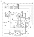
- FIG. 1 is an overall configuration diagram of a refrigeration cycle device in which an outdoor unit according to the first embodiment is used.
- FIG. 1 functionally shows the connection relationship and the arrangement configuration of each device in the refrigeration cycle apparatus, and does not necessarily show the arrangement in the physical space.
- the refrigeration cycle device 1 includes an outdoor unit 2 and an indoor unit 3.
- the outdoor unit 2 includes a compressor 10, a condenser 20, a fan 22, a liquid reservoir 30, a supercooling heat exchanger 40, a fan 42, a sight glass 45, and pipes 80 to 83, 85.
- the outdoor unit 2 further includes pipes 86 and 87, a refrigerant amount detection unit 70, a suction pressure sensor 90, a discharge pressure sensor 92, a control device 100, and a display device 150.
- the indoor unit 3 includes an expansion mechanism 50, an evaporator 60, a fan 62, and a pipe 84.
- the indoor unit 3 is connected to the outdoor unit 2 through pipes 83 and 85.
- the pipe 80 connects the discharge port of the compressor 10 and the condenser 20.
- the pipe 81 connects the condenser 20 and the liquid reservoir 30.
- the pipe 82 connects the liquid reservoir 30 and the supercooling heat exchanger 40.
- the pipe 83 connects the supercooling heat exchanger 40 and the expansion mechanism 50.
- the pipe 84 connects the expansion mechanism 50 and the evaporator 60.
- the pipe 85 connects the evaporator 60 and the suction port of the compressor 10.
- the pipe 86 connects the pipe 82 and the refrigerant amount detection unit 70.
- the pipe 87 connects the refrigerant amount detection unit 70 and the pipe 85.
- the compressor 10 compresses the refrigerant sucked from the pipe 85 and outputs it to the pipe 80.
- the compressor 10 is configured to adjust the rotation speed according to a control signal from the control device 100. By adjusting the rotation speed of the compressor 10, the circulation amount of the refrigerant is adjusted, and the capacity of the refrigeration cycle device 1 can be adjusted.
- Various types of compressors 10 can be adopted, and for example, scroll type, rotary type, screw type and the like can be adopted.
- the condenser 20 condenses the refrigerant output from the compressor 10 to the pipe 80 and outputs the refrigerant to the pipe 81.
- the condenser 20 is configured such that a high-temperature and high-pressure gas refrigerant output from the compressor 10 exchanges heat (heat dissipation) with the outside air. By this heat exchange, the refrigerant is condensed and changed to a liquid phase.
- the fan 22 supplies the condenser 20 with outside air through which the refrigerant exchanges heat in the condenser 20. By adjusting the rotation speed of the fan 22, the refrigerant pressure (high pressure side pressure) on the discharge side of the compressor 10 can be adjusted.
- the liquid reservoir 30 stores the high-pressure liquid refrigerant condensed by the condenser 20.
- the supercooling heat exchanger 40 is configured such that the liquid refrigerant output from the liquid reservoir 30 to the pipe 82 further exchanges heat (heat dissipation) with the outside air.
- the refrigerant becomes a supercooled liquid refrigerant by passing through the supercooled heat exchanger 40.
- the fan 42 supplies the outside air through which the refrigerant exchanges heat in the supercooling heat exchanger 40 to the supercooling heat exchanger 40.
- the sight glass 45 is a window for visually confirming air bubbles (flash gas) in the refrigerant flowing through the pipe 83.
- the expansion mechanism 50 decompresses the refrigerant output from the supercooling heat exchanger 40 to the pipe 83 and outputs the refrigerant to the pipe 84.
- an expansion valve can be used as the expansion mechanism 50.
- the opening degree of the expansion valve is changed in the closing direction, the refrigerant pressure on the outlet side of the expansion valve decreases, and the dryness of the refrigerant increases.
- the opening degree of the expansion valve is changed in the opening direction, the refrigerant pressure on the outlet side of the expansion valve increases, and the dryness of the refrigerant decreases.
- a capillary tube may be used instead of the expansion valve.
- the evaporator 60 evaporates the refrigerant output from the expansion mechanism 50 to the pipe 84 and outputs the refrigerant to the pipe 85.
- the evaporator 60 is configured such that the refrigerant decompressed by the expansion mechanism 50 exchanges heat (endothermic) with the air in the indoor unit 3.
- the refrigerant evaporates as it passes through the evaporator 60 to become superheated steam.
- the fan 62 supplies the evaporator 60 with outside air through which the refrigerant exchanges heat in the evaporator 60.
- Refrigerant circulates in the compressor 10, the pipe 82, the condenser 20, the pipe 81, the liquid reservoir 30, the pipe 82, the overcooling heat exchanger 40, the pipe 83, the expansion mechanism 50, the pipe 84, the evaporator 60, and the pipe 85.
- the refrigerant circuit 5 to be used is formed.
- the refrigerant amount detecting unit 70 is provided between the pipe 86 branching from the pipe 82 and the pipe 87 connected to the pipe 85.
- the pipe 86, the refrigerant amount detection unit 70, and the pipe 87 form a “bypass circuit” that returns a part of the refrigerant on the outlet side of the condenser 20 to the compressor 10 without passing through the indoor unit 3.
- the refrigerant amount detection unit 70 includes a capillary tube (decompression device) 71, a heater 72, and temperature sensors 73 and 74.
- the capillary tube 71 is connected between the pipe 86 and the pipe 87 to reduce the pressure of the refrigerant flowing in the bypass circuit.
- the capillary tube 71 is a gas-liquid two-phase so that the refrigerant that has passed through the capillary tube 71 is heated by the heater 72 without becoming a gas single phase. It is appropriately designed in consideration of the amount of heating.
- An expansion valve may be used instead of the capillary tube 71.
- the heater 72 and the temperature sensors 73 and 74 are provided in the pipe 87.
- the heater 72 heats the refrigerant that has passed through the capillary tube 71.
- the enthalpy of the refrigerant is increased by being heated by the heater 72.
- the heater 72 has a gas-liquid two-phase without becoming a gas single phase even when the refrigerant passing through the capillary tube 71 is heated by the heater 72, so that the heating amount is increased together with the specifications of the capillary tube 71.
- the heater 72 may heat the refrigerant from the outside of the pipe 87, or may be installed inside the pipe 87 in order to more reliably transfer heat from the heater 72 to the refrigerant.
- the heater 72 may be always ON. Alternatively, the heater 72 may be turned on only during the refrigerant shortage determination process. Alternatively, the heater 72 may be turned on only when the compressor 10 is activated. In the first embodiment, it is assumed that the heater 72 is turned on only during the refrigerant shortage determination process.
- the refrigerant amount detection unit 70 further includes a solenoid valve 79.
- the solenoid valve 79 is provided in the pipe 86 upstream of the capillary tube 71, and opens and closes according to an instruction from the control device 100.
- the solenoid valve 79 is opened, the refrigerant flows through the capillary tube 71 and the pipe 87, and the refrigerant shortage can be detected.
- the solenoid valve 79 is in the closed state, the flow of the refrigerant to the capillary tube 71 and the pipe 87 is blocked, so that the refrigerant shortage detection cannot be performed.
- the solenoid valve 79 may be always ON. Alternatively, the solenoid valve 79 may be turned on only during the refrigerant shortage determination process. In the first embodiment, it is assumed that the solenoid valve 79 is turned on only during the refrigerant shortage determination process.
- the solenoid valve 79 is provided in the pipe 86, but the solenoid valve 79 may be provided in the pipe 87 downstream of the capillary tube 71. However, if the solenoid valve 79 is arranged on the upstream side in the bypass circuit, the amount of liquid refrigerant that normally falls asleep in the bypass circuit can be reduced, so it is preferable to provide the solenoid valve 79 in the pipe 86. Further, it is more preferable that the solenoid valve 79 is provided at a position as close as possible to the branch portion where the pipe 86 is branched from the pipe 82.
- the temperature sensor 73 detects the refrigerant temperature before the refrigerant is heated by the heater 72, that is, the temperature T1 of the refrigerant between the capillary tube 71 and the heater 72, and outputs the detected value to the control device 100.
- the temperature sensor 74 detects the refrigerant temperature after the refrigerant is heated by the heater 72, that is, the temperature T2 of the refrigerant downstream of the heater 72 and before joining the pipe 85, and outputs the detected value to the control device 100.
- the temperature sensors 73 and 74 may be installed outside the pipe 87, or may be installed inside the pipe 87 in order to more reliably detect the temperature of the refrigerant. The principle and method of determining the refrigerant shortage by the refrigerant amount detecting unit 70 will be described in detail later.
- the suction pressure sensor 90 detects the suction pressure LP of the refrigerant in the pipe 85 and outputs the detected value to the control device 100. That is, the suction pressure sensor 90 detects the refrigerant pressure (low pressure side pressure) LP on the suction side of the compressor 10.
- the discharge pressure sensor 92 detects the discharge pressure HP of the refrigerant in the pipe 80 and outputs the detected value to the control device 100. That is, the discharge pressure sensor 92 detects the refrigerant pressure (high pressure side pressure) HP on the discharge side of the compressor 10.
- the suction temperature sensor 302 is arranged around the suction port of the compressor 10.
- the suction temperature sensor 302 detects the suction temperature Ts of the refrigerant into the compressor 10.
- the evaporation temperature sensor 303 detects the temperature of the refrigerant flowing through the evaporator 60 as the evaporation temperature Te of the refrigerant.
- the control device 100 includes a CPU (Central Processing Unit) 102, a memory 104 (ROM (Read Only Memory) and a RAM (Random Access Memory)), an input / output buffer (not shown) for inputting / outputting various signals, and the like. Consists of including.
- the CPU 102 expands the program stored in the ROM into a RAM or the like and executes the program.
- the program stored in the ROM is a program in which the processing procedure of the control device 100 is described.
- the control device 100 executes control of each device in the outdoor unit 2 according to these programs. This control is not limited to software processing, but can also be processed by dedicated hardware (electronic circuit).
- the display device 150 displays information such as the status of the refrigeration cycle device 1 sent from the control device 100 in order to notify the user or the operator.
- the refrigerant shortage occurs when the initial filling amount of the refrigerant in the refrigerant circuit is insufficient, or when the refrigerant leaks after the start of use.
- FIG. 2 is a diagram conceptually showing the state of the refrigerant around the heater 72 in the normal state when the refrigerant shortage does not occur.
- normal time when the refrigerant is not insufficient and the amount of the refrigerant is within an appropriate range, it may be simply referred to as "normal time”.
- FIG. 3 is a diagram showing an example of a change in the refrigerant temperature due to the heater 72 in a normal state.
- the horizontal axis indicates the position of the pipe 87 in the extension direction
- P1 and P2 indicate the positions where the temperature sensors 73 and 74 are installed, respectively.
- the vertical axis shows the refrigerant temperature at each position of the pipe 87.
- FIG. 3 shows a case where the refrigerant is an azeotropic refrigerant (a refrigerant having no temperature gradient, for example, a refrigerant such as R410a).
- the refrigerant passing through the capillary tube 71 has a large amount of liquid components, so that the temperature of the refrigerant basically does not change even if the refrigerant is heated by the heater 72 (heating energy is high). It is used to change the latent heat of the refrigerant.) Therefore, the temperature T2 of the refrigerant after heating the refrigerant by the heater 72 is substantially the same as the temperature T1 of the refrigerant before heating the refrigerant by the heater 72.
- the refrigerant is a non-azeotropic refrigerant (a refrigerant having a temperature gradient, for example, a refrigerant such as R407a, R448a, R449a, R463a), the temperature of the refrigerant rises slightly due to heating by the heater 72. (At most about 10 degrees).
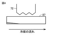
- FIG. 4 is a diagram conceptually showing the state of the refrigerant around the heater 72 when the refrigerant is insufficient.
- the refrigerant when the refrigerant is insufficient, the refrigerant is gas-liquid two-phase at the outlet of the condenser 20, and the liquid refrigerant is not accumulated in the liquid reservoir 30, or even if it is accumulated. It is a small amount.
- the gas-liquid two-phase refrigerant flows through the pipe 86, and the refrigerant that has passed through the capillary tube 71 has a larger amount of gas components than in the normal state. Therefore, the refrigerant that has passed through the capillary tube 71 is heated by the heater 72 and evaporates, and the temperature (superheat degree) rises.
- FIG. 5 is a diagram showing an example of a change in the refrigerant temperature due to the heater 72 when the refrigerant is insufficient. Also in FIG. 5, the horizontal axis indicates the position of the pipe 87 in the extension direction, and P1 and P2 indicate the positions where the temperature sensors 73 and 74 are installed, respectively. The vertical axis shows the refrigerant temperature at each position of the pipe 87.
- the refrigerant that has passed through the capillary tube 71 has a large amount of gas components. Therefore, when the refrigerant is heated by the heater 72, the refrigerant evaporates and the temperature of the refrigerant rises. (Superheat> 0). Therefore, the temperature T2 of the refrigerant after heating the refrigerant by the heater 72 is higher than the temperature T1 of the refrigerant before heating the refrigerant by the heater 72.
- the temperature rise of the refrigerant by the heater 72 when the refrigerant is insufficient and the temperature rise of the refrigerant by the heater 72 when the refrigerant is normal can be distinguished.
- the heating amount of the heater 72 is appropriately set.
- the refrigerant amount detection unit 70 can determine whether or not there is a refrigerant shortage in the refrigerant circuit based on the amount of temperature rise of the refrigerant when the refrigerant is heated by the heater 72.
- the control device 100 acquires the suction temperature Ts of the compressor 10 detected by the suction temperature sensor 302.
- the control device 100 acquires the suction pressure LP of the compressor 10 detected by the suction pressure sensor 90.
- the control device 100 calculates the saturation temperature ST (LP) of the suction pressure LP.
- the control device 100 calculates the suction superheat degree SH of the compressor 10 by subtracting the saturation temperature ST (LP) of the suction pressure LP of the compressor 10 from the suction temperature Ts of the compressor 10.
- the control device 100 acquires the evaporation temperature Te of the refrigerant detected by the evaporation temperature sensor 303.
- the control device 100 may calculate the evaporation temperature Te of the refrigerant by converting the suction pressure LP detected by the suction pressure sensor 90 into the refrigerant saturated gas temperature.
- the control device 100 determines whether or not the refrigerant circulating in the refrigerant circuit 5 is insufficient, and when it is determined that the refrigerant is insufficient, the control device 100 notifies the cause of the refrigerant shortage as follows.
- the control device 100 determines the refrigerant circuit 5 when the difference (T2-T1) between the temperature T1 detected by the temperature sensor 73 of the refrigerant amount detection unit 70 and the temperature T2 detected by the temperature sensor 74 is the threshold value Th1 or more. It is determined that the refrigerant circulating inside is insufficient.
- the suction superheat degree SH of the compressor 10 becomes small.
- a large amount of refrigerant moves to the suction side of the compressor 10, so that the amount of refrigerant supplied to the refrigerant amount detection unit 70 decreases.
- the control device 100 causes the liquid back as a factor when the suction superheat degree SH of the compressor 10 is smaller than the threshold value Th2. Notify that you are driving.
- the amount of refrigerant on the low pressure side of the refrigerant circuit 5 is large, so that the amount of refrigerant supplied to the refrigerant amount detection unit 70 is reduced. As a result, it is determined that the refrigerant circulating in the refrigerant circuit 5 is insufficient. Therefore, when the control device 100 determines that the refrigerant circulating in the refrigerant circuit 5 is insufficient and the evaporation temperature Te of the refrigerant is the threshold value Th3 or more, the evaporation temperature of the refrigerant is a factor. Notify that the driving is high.
- the control device 100 determines that the refrigerant circulating in the refrigerant circuit 5 is insufficient, the suction superheat degree SH of the compressor 10 is a threshold value Th2 or more, and the refrigerant evaporation temperature Te is a threshold. If the value is less than Th3, the refrigerant circuit 5 notifies the outside of the refrigerant as a factor.
- FIG. 6 is a flowchart showing an example of a refrigerant shortage determination processing procedure executed by the control device in the first embodiment. The series of processes shown in this flowchart are repeatedly executed while the refrigeration cycle device 1 is in steady operation.
- step S101 the control device 100 determines whether or not the refrigerant shortage determination control is being executed. Refrigerant shortage determination control is executed, for example, once an hour for several minutes. When the refrigerant shortage determination control is not executed (NO in step S101), the control device 100 shifts the process to the return without executing the subsequent series of processes. If it is determined that the refrigerant shortage determination control is being executed (YES in step S101), the process proceeds to step S102.
- step S102 the control device 100 turns on (opens) the solenoid valve 79 and turns on the heater 72.
- step S103 the control device 100 acquires the detected values of the temperatures T1 and T2 from the temperature sensors 73 and 74 of the refrigerant amount detecting unit 70, respectively.
- step S104 the control device 100 determines whether or not the difference between the acquired temperature T2 and the temperature T1 (T2-T1), that is, the amount of temperature rise of the refrigerant by the heater 72 is equal to or greater than the threshold value Th1. To do. When it is determined that the amount of temperature rise of the refrigerant by the heater 72 is equal to or higher than the threshold value Th1 (S104: YES), the control device 100 determines that the refrigerant circulating in the refrigerant circuit 5 is insufficient, and processes the refrigerant. Proceeds to step S105.
- the control device 100 determines that the refrigerant circulating in the refrigerant circuit 5 is not insufficient, and processes the refrigerant. Proceeds to step S110.
- step S105 the control device 100 determines whether or not the suction superheat degree SH of the compressor 10 is less than the threshold value Th2. When it is determined that the suction superheat degree SH of the compressor 10 is less than the threshold value Th2 (S105: YES), the process proceeds to step S107. When it is determined that the suction superheat degree SH of the compressor 10 is equal to or higher than the threshold value Th2 (S105: NO), the process proceeds to step S106.
- step S106 the control device 100 determines whether or not the evaporation temperature Te of the refrigerant is the threshold value Th3 or more. When it is determined that the evaporation temperature Te of the refrigerant is equal to or higher than the threshold value Th3 (S106: YES), the process proceeds to step S108. When it is determined that the evaporation temperature Te of the refrigerant is less than the threshold value Th3 (S106: NO), the process proceeds to step S109.
- step S107 the control device 100 displays on the display device 150 that it is determined that the refrigerant circulating in the refrigerant circuit 5 is insufficient due to the liquid back operation.
- step S108 the control device 100 displays on the display device 150 that it is determined that the refrigerant circulating in the refrigerant circuit 5 is insufficient due to the operation in which the evaporation temperature of the refrigerant is high.
- step S109 the control device 100 displays on the display device 150 that it is determined that the refrigerant circulating in the refrigerant circuit 5 is insufficient because the refrigerant sealed in the refrigerant circuit 5 leaks to the outside.
- step S110 the control device 100 turns off (closes) the solenoid valve 79 and turns off the heater 72.
- the threshold value Th1 in step S104 determines the type of refrigerant used and the heater 72 so that the amount of temperature rise of the refrigerant in the normal state by the heater 72 and the amount of temperature rise in the case of insufficient refrigerant can be distinguished. It is appropriately set based on the amount of heating.
- the refrigerant amount detecting unit 70 is arranged at a position that is not easily affected by the wind that disturbs the detection of the temperature rise amount. Specifically, the refrigerant amount detection unit 70 is arranged at a location where the influence of the air flow is small as compared with the condenser 20.
- the wind to be affected is included, the wind that has passed through the condenser 20, the wind before passing through the condenser 20, and the natural wind. As a result, it is possible to prevent the refrigerant amount detecting unit 70 from being affected by the wind and causing an error in the above-mentioned temperature rise amount.
- FIG. 7 is a diagram schematically showing the structure of the outdoor unit 2 of the refrigeration cycle device 1.
- the heat exchange chamber 202 houses a condenser 20, a liquid reservoir 30, a supercooled heat exchanger 40 (none of which is shown), and fans 22 and 42.
- the condenser 20 and the supercooling heat exchanger 40 (hereinafter, may be collectively referred to as “heat exchange section”) and the fans 22 and 42 are provided on the side surface of the housing of the outdoor unit 2, and this example.
- the machine room 204 houses the compressor 10, each pipe, the suction pressure sensor 90, the discharge pressure sensor 92, and the control device 100.
- the refrigerant amount detecting unit 70 is housed in the machine room 204.
- a wind accompanying the operation of the fans 22 and 42, or a natural wind is flowing while the fan is stopped.
- the refrigerant amount detecting unit 70 is arranged in the heat exchange chamber 202 through which such wind flows, the refrigerant amount detecting unit 70 (particularly the temperature sensors 73 and 74) is affected by the wind, so that the temperature of the refrigerant by the heater 72 is generated. An error may occur in the measurement of the amount of rise.
- the refrigerant amount detection unit 70 since the refrigerant amount detection unit 70 is housed in the machine room 204 separated from the heat exchange room 202 by the partition plate 206, it is not affected by the wind. Therefore, according to the outdoor unit 2, the amount of temperature rise of the refrigerant by the heater 72 can be measured with high accuracy.
- the liquid reservoir 30 is arranged in the heat exchange chamber 202, but it may be arranged in the machine room 204.
- the refrigerant is based on the amount of temperature rise of the refrigerant that has passed through the heater 72, regardless of whether the degree of supercooling of the refrigerant is large or small or a non-azeotropic refrigerant is used. The shortage can be determined.
- the first embodiment it is possible to notify the operator or the user of the factor determined to be the refrigerant shortage. As a result, it is possible to take measures according to the factors determined to be insufficient refrigerant.
- the refrigerant amount detecting unit 70 is arranged in the machine room 204 which is not affected by the wind, the above-mentioned temperature rise amount has an error due to the influence of the wind on the refrigerant amount detecting unit 70. Can be avoided. As a result, according to the first embodiment, it is possible to accurately determine the shortage of the refrigerant in the refrigerant circuit 5.
- Embodiment 2 As the heat source in the refrigerant amount detection unit, a high-temperature and high-pressure refrigerant on the discharge side of the compressor 10 is used instead of the heater 72. As a result, the refrigerant amount detection unit can be configured without separately providing the heater 72.
- FIG. 8 is an overall configuration diagram of a refrigeration cycle device in which the outdoor unit according to the second embodiment is used.
- the refrigeration cycle device 1A includes an outdoor unit 2A and an indoor unit 3.
- the outdoor unit 2A includes a refrigerant amount detection unit 70A and a control device 100A, respectively, in place of the refrigerant amount detection unit 70 and the control device 100 in the outdoor unit 2 of the first embodiment shown in FIG.
- the refrigerant amount detection unit 70A includes a heat exchange unit 78 instead of the heater 72 in the refrigerant amount detection unit 70 of the first embodiment shown in FIG. 1, and further includes temperature sensors 75 to 77.
- the heat exchange unit 78 is configured to exchange heat between the high-temperature and high-pressure refrigerant output from the compressor 10 and the refrigerant that has passed through the capillary tube 71.
- the temperature sensor 73 detects the refrigerant temperature on the upstream side of the heat exchange unit 78, that is, the temperature T1 of the refrigerant between the capillary tube 71 and the heat exchange unit 78.
- the temperature sensor 74 detects the temperature of the refrigerant on the downstream side of the heat exchange unit 78, that is, the temperature T2 of the refrigerant downstream of the heat exchange unit 78 and before merging with the pipe 85.
- the temperature sensor 75 detects the temperature T3 of the high-temperature and high-pressure refrigerant output from the compressor 10, and outputs the detected value to the control device 100A.
- the temperature sensor 76 detects the temperature T4 of the refrigerant output from the compressor 10 and passed through the heat exchange unit 78, and outputs the detected value to the control device 100A. That is, the temperature sensors 75 and 76 detect the temperatures of the refrigerants supplied from the compressor 10 to the condenser 20 before and after the passage of the heat exchange unit 78, respectively.
- the temperature sensor 77 detects the temperature T5 of the refrigerant sucked into the compressor 10 and outputs the detected value to the control device 100A.
- the control device 100A determines whether or not there is a refrigerant shortage in the refrigerant circuit 5A based on the amount of temperature rise of the refrigerant when the refrigerant flowing through the pipe 87 is heated by the heat exchange unit 78. More specifically, the control device 100A determines that the refrigerant shortage has occurred when the temperature rise amount of the refrigerant by the heat exchange unit 78 becomes equal to or more than the threshold value.
- the temperature rise amount of the refrigerant in the pipe 87 in the heat exchange unit 78 also changes depending on the operating state of the refrigerating cycle device 1A. ..
- the refrigerant is a non-azeotropic refrigerant
- the refrigerant is an azeotropic refrigerant
- the temperature of the refrigerant may rise if the amount of heat of the heat exchange unit 78 is large.
- the heating amount of the heat exchange unit 78 is calculated, and the threshold value for determining whether or not the refrigerant is insufficient (refrigerant in the heat exchange unit 78) is calculated based on the heating amount. Threshold for the amount of temperature rise) is set. As a result, even if the heating amount of the heat exchange unit 78 changes depending on the operating state of the refrigeration cycle device 1A, the refrigerant shortage can be accurately determined.
- the amount of heat of the heat exchange unit 78 can be calculated as follows, for example.
- Heating amount G ⁇ H... (1)
- G is the flow rate of the refrigerant flowing from the compressor 10 to the heat exchange unit 78
- H is the enthalpy difference of the refrigerant flowing from the compressor 10 to the heat exchange unit 78 before and after the heat exchange unit 78.
- the refrigerant flow rate G (kg / hr) can be calculated by the following equation.
- Refrigerant flow rate G V ⁇ R ⁇ D... (2)
- V is the amount of displacement (m 3 ) of the compressor 10, that is, the amount of refrigerant sucked per rotation of the compressor 10.
- R is the rotation speed (1 / hr or 1 / s) of the compressor 10
- D is the density of the refrigerant (kg / m 3 ).
- the density D is an amount determined by the refrigerant temperature and pressure on the suction side of the compressor 10, and can be calculated from the temperature T5 detected by the temperature sensor 77 and the suction pressure LP detected by the suction pressure sensor 90. it can.
- the enthalpy difference H (kJ / kg) can be calculated by the following equation.
- Enthalpy difference H H3-H4 ... (3)
- H3 is the enthalpy of the refrigerant supplied from the compressor 10 to the heat exchange unit 78
- H4 is the enthalpy of the refrigerant after passing through the heat exchange unit 78.
- the enthalpy H3 is an amount determined by the discharge pressure HP of the compressor 10 and the refrigerant temperature before passing through the heat exchange unit 78, and is detected by the discharge pressure HP detected by the discharge pressure sensor 92 and the temperature sensor 75. It can be obtained from the temperature T3.
- the enthalpy H4 is an amount determined by the discharge pressure HP of the compressor 10 and the refrigerant temperature after passing through the heat exchange unit 78, and can be obtained from the discharge pressure HP and the temperature T4 detected by the temperature sensor 76. it can.
- FIG. 9 is a flowchart showing an example of a processing procedure for determining a refrigerant shortage executed by the control device 100A in the second embodiment. The series of processes shown in this flowchart are repeatedly executed while the refrigeration cycle apparatus 1A is in steady operation.
- step S201 the control device 100A determines whether or not the refrigerant shortage determination control is being executed. Refrigerant shortage determination control is executed, for example, once an hour for several minutes. When the refrigerant shortage determination control is not executed (NO in step S201), the control device 100A shifts the process to the return without executing the subsequent series of processes. If it is determined that the refrigerant shortage determination control is being executed (YES in step S201), the process proceeds to step S202.
- step S202 the control device 100A acquires the detected values of the temperatures T1 to T5 from the temperature sensors 73 to 77, respectively, acquires the rotation speed R of the compressor 10, and further acquires the rotation speed R of the compressor 10 from the suction pressure sensor 90 and the discharge pressure sensor 92, respectively. Acquire the detected values of the suction pressure LP and the discharge pressure HP.
- step S203 the control device 100A calculates the refrigerant flow rate G using the above formula (2) and calculates the enthalpy difference H using the above formula (3).
- step S204 the control device 100A calculates the heating amount (G ⁇ H) of the heat exchange unit 78 by multiplying the calculated refrigerant flow rate G by the enthalpy difference H.
- step S205 the control device 100A flows through the threshold value Th4 (flows through the pipe 87 in the heat exchange unit 78) for determining whether or not there is a refrigerant shortage based on the calculated heating amount of the heat exchange unit 78. Set the threshold value for the amount of temperature rise of the refrigerant).
- the relationship between the heating amount and the threshold value Th4 is obtained in advance by pre-evaluation, simulation, etc. according to the type of the refrigerant used, and is stored in the ROM of the control device 100A.
- step S206 the control device 100A has a threshold value Th4 of the difference between the temperature T2 and the temperature T1 (T2-T1) acquired in step S202, that is, the amount of temperature rise of the refrigerant flowing through the pipe 87 in the heat exchange unit 78. Determine if it is above or not.
- Th4 the threshold value
- the control device 100A determines that the refrigerant circulating in the refrigerant circuit 5 is insufficient, and the process is step S207. Proceed to.
- the control device 100A determines that the refrigerant circulating in the refrigerant circuit 5 is not insufficient, and processes it as a return. Migrate.
- step S207 the control device 100A determines whether or not the suction superheat degree SH of the compressor 10 is less than the threshold value Th2. When it is determined that the suction superheat degree SH of the compressor 10 is less than the threshold value Th2 (S207: YES), the process proceeds to step S209. When it is determined that the suction superheat degree SH of the compressor 10 is equal to or higher than the threshold value Th2 (S207: NO), the process proceeds to step S208.
- step S208 the control device 100A determines whether or not the evaporation temperature Te of the refrigerant is the threshold value Th3 or more. When it is determined that the evaporation temperature Te of the refrigerant is equal to or higher than the threshold value Th3 (S1208: YES), the process proceeds to step S210. When it is determined that the evaporation temperature Te of the refrigerant is less than the threshold value Th3 (S208: NO), the process proceeds to step S211.
- step S209 the control device 100A displays on the display device 150 that it is determined that the refrigerant circulating in the refrigerant circuit 5 is insufficient due to the liquid back operation.
- step S210 the control device 100A displays on the display device 150 that it is determined that the refrigerant circulating in the refrigerant circuit 5 is insufficient due to the operation in which the evaporation temperature of the refrigerant is high.
- step S211 the control device 100A displays on the display device 150 that it is determined that the refrigerant circulating in the refrigerant circuit 5 is insufficient because the refrigerant sealed in the refrigerant circuit 5 leaks to the outside.
- the heat exchange unit 78 using the high temperature and high pressure refrigerant on the discharge side of the compressor 10 is provided instead of the heater 72.
- the refrigerant amount detection unit can be configured without providing the heater 72.
- the heating amount of the heat exchange unit 78 changes depending on the operating state of the refrigerating cycle apparatus 1A.
- the threshold value Th4 of the temperature rise amount of the refrigerant flowing through the pipe 87 in the heat exchange unit 78 Is set based on the heating amount of the heat exchange unit 78, so that the refrigerant shortage can be accurately determined even if the operating state of the refrigerating cycle apparatus 1A changes.
- the second embodiment as in the first embodiment, it is possible to notify the operator or the user of the factor determined to be the refrigerant shortage. As a result, it is possible to take measures according to the factors determined to be insufficient refrigerant.
- FIG. 10 is an overall configuration diagram of a refrigeration cycle device in which the outdoor unit according to the third embodiment is used.
- the refrigeration cycle device 1C includes an outdoor unit 2C and an indoor unit 3.
- the outdoor unit 2C includes a control device 100C instead of the control device 100 of the outdoor unit 2 of the first embodiment shown in FIG.
- the outdoor unit 2C further includes a condensation temperature sensor 305 and a liquid refrigerant temperature sensor 304.
- the condensation temperature sensor 305 is provided at the inlet of the supercooling heat exchanger 40.
- the condensation temperature sensor 305 detects the temperature of the refrigerant as the condensation temperature Tx.
- the liquid refrigerant temperature sensor 304 is provided at the outlet of the supercooling heat exchanger 40.
- the liquid refrigerant temperature sensor 304 detects the temperature of the refrigerant as the liquid refrigerant temperature Ty.
- the control device 100C calculates the degree of supercooling SC of the refrigerant at the outlet of the supercooling heat exchanger 40 by subtracting the liquid refrigerant temperature Ty from the condensation temperature Tx.
- the control device 100C determines that the refrigerant circulating in the refrigerant circuit 5 is insufficient when the supercooling degree SC is the threshold value Th5 or less.
- FIG. 11 is a flowchart showing an example of a processing procedure for determining a refrigerant shortage executed by the control device 100C in the third embodiment. The series of processes shown in this flowchart are repeatedly executed while the refrigeration cycle apparatus 1C is in steady operation.
- step S301 the control device 100C determines whether or not the refrigerant shortage determination control is being executed. Refrigerant shortage determination control is executed, for example, once an hour for several minutes. When the refrigerant shortage determination control is not executed (NO in step S301), the control device 100C shifts the process to the return without executing the subsequent series of processes. If it is determined that the refrigerant shortage determination control is being executed (YES in step S301), the process proceeds to step S302.
- step S302 the control device 100C acquires the condensation temperature Tx from the condensation temperature sensor 305 and acquires the liquid refrigerant temperature Ty from the liquid refrigerant temperature sensor 304.
- step S303 the control device 100C calculates the degree of supercooling SC of the refrigerant at the outlet of the supercooling heat exchanger 40 based on the condensation temperature Tx and the liquid refrigerant temperature Ty.
- step S304 the control device 100C determines whether or not the supercooling degree SC is the threshold value Th5 or less.
- the control device 100C determines that the refrigerant circulating in the refrigerant circuit 5 is insufficient, and the process proceeds to step S305. move on.
- the control device 100C determines that the refrigerant circulating in the refrigerant circuit 5 is not insufficient, and shifts the process to return. To do.
- step S305 the control device 100C determines whether or not the suction superheat degree SH of the compressor 10 is less than the threshold value Th2. When it is determined that the suction superheat degree SH of the compressor 10 is less than the threshold value Th2 (S305: YES), the process proceeds to step S307. When it is determined that the suction superheat degree SH of the compressor 10 is equal to or higher than the threshold value Th2 (S305: NO), the process proceeds to step S306.
- step S306 the control device 100C determines whether or not the evaporation temperature Te of the refrigerant is the threshold value Th3 or more. When it is determined that the evaporation temperature Te of the refrigerant is equal to or higher than the threshold value Th3 (S306: YES), the process proceeds to step S308. When it is determined that the evaporation temperature Te of the refrigerant is less than the threshold value Th3 (S306: NO), the process proceeds to step S309.
- step S307 the control device 100C displays on the display device 150 that it is determined that the refrigerant circulating in the refrigerant circuit 5 is insufficient due to the liquid back operation.
- step S308 the control device 100C displays on the display device 150 that it is determined that the refrigerant circulating in the refrigerant circuit 5 is insufficient due to the operation in which the evaporation temperature of the refrigerant is high.
- step S309 the control device 100C displays on the display device 150 that it is determined that the refrigerant circulating in the refrigerant circuit 5 is insufficient because the refrigerant sealed in the refrigerant circuit 5 leaks to the outside.
- the third embodiment it is possible to determine whether or not the refrigerant is insufficient based on the degree of supercooling SC of the refrigerant at the outlet of the supercooling heat exchanger 40.
- the operator or the user can be notified of the factor determined to be the refrigerant shortage. As a result, it is possible to take measures according to the factors determined to be insufficient refrigerant.
- FIG. 12 is an overall configuration diagram of a refrigeration cycle device in which the outdoor unit according to the fourth embodiment is used.
- the refrigeration cycle device 1D includes an outdoor unit 2D and an indoor unit 3.
- the outdoor unit 2D includes a control device 100D instead of the control device 100 of the outdoor unit 2 of the first embodiment shown in FIG.
- the outdoor unit 2D further includes a condensation temperature sensor 305, a liquid refrigerant temperature sensor 304, and an outside air temperature sensor 301.
- the outside air temperature sensor 301 is provided around the condenser 20.
- the outside air temperature sensor 301 detects the outside air temperature To.
- the condensation temperature sensor 305 is provided at the inlet of the supercooling heat exchanger 40.
- the condensation temperature sensor 305 detects the temperature of the refrigerant as the condensation temperature Tx.
- the liquid refrigerant temperature sensor 304 is provided at the outlet of the supercooling heat exchanger 40.
- the liquid refrigerant temperature sensor 304 detects the temperature of the refrigerant as the liquid refrigerant temperature Ty.
- the control device 100D calculates the degree of supercooling SC of the refrigerant at the outlet of the supercooling heat exchanger 40 by subtracting the liquid refrigerant temperature Ty from the condensation temperature Tx.
- the control device 100D sets the degree of refrigerant supercooling (condensation temperature Tx-liquid refrigerant temperature Ty) at the outlet of the supercooling heat exchanger 40 to the maximum temperature difference of the supercooling heat exchanger 40 (condensation temperature Tx-outside air temperature To). By dividing, the temperature efficiency ⁇ of the supercooling heat exchanger 40 is calculated.
- the control device 100D determines that the refrigerant circulating in the refrigerant circuit 5 is insufficient.
- FIG. 13 is a flowchart showing an example of a processing procedure for determining a refrigerant shortage executed by the control device 100D in the fourth embodiment. The series of processes shown in this flowchart are repeatedly executed while the refrigeration cycle apparatus 1D is in steady operation.
- step S401 the control device 100D determines whether or not the refrigerant shortage determination control is being executed. Refrigerant shortage determination control is executed, for example, once an hour for several minutes. When the refrigerant shortage determination control is not executed (NO in step S401), the control device 100D shifts the process to the return without executing the subsequent series of processes. If it is determined that the refrigerant shortage determination control is being executed (YES in step S401), the process proceeds to step S402.
- step S402 the control device 100D acquires the condensation temperature Tx from the condensation temperature sensor 305, acquires the liquid refrigerant temperature Ty from the liquid refrigerant temperature sensor 304, and acquires the outside air temperature To from the outside air temperature sensor 301.
- step S403 the control device 100D calculates the temperature efficiency ⁇ of the supercooling heat exchanger 40 based on the outside air temperature To, the condensation temperature Tx, and the liquid refrigerant temperature Ty.
- step S404 the control device 100D determines whether or not the temperature efficiency ⁇ of the supercooling heat exchanger 40 is equal to or less than the threshold value Th6.
- the control device 100D determines that the refrigerant circulating in the refrigerant circuit 5 is insufficient.
- the process proceeds to step S405.
- the control device 100D determines that the refrigerant circulating in the refrigerant circuit 5 is not insufficient. Move the process to return.
- step S405 the control device 100D determines whether or not the suction superheat degree SH of the compressor 10 is less than the threshold value Th2. When it is determined that the suction superheat degree SH of the compressor 10 is less than the threshold value Th2 (S405: YES), the process proceeds to step S407. When it is determined that the suction superheat degree SH of the compressor 10 is equal to or higher than the threshold value Th2 (S405: NO), the process proceeds to step S406.
- step S406 the control device 100D determines whether or not the evaporation temperature Te of the refrigerant is the threshold value Th3 or more. When it is determined that the evaporation temperature Te of the refrigerant is equal to or higher than the threshold value Th3 (S406: YES), the process proceeds to step S408. When it is determined that the evaporation temperature Te of the refrigerant is less than the threshold value Th3 (S406: NO), the process proceeds to step S409.
- step S407 the control device 100D displays on the display device 150 that it is determined that the refrigerant circulating in the refrigerant circuit 5 is insufficient due to the liquid back operation.
- step S408 the control device 100D displays on the display device 150 that it is determined that the refrigerant circulating in the refrigerant circuit 5 is insufficient due to the operation in which the evaporation temperature of the refrigerant is high.
- step S409 the control device 100D displays on the display device 150 that it is determined that the refrigerant circulating in the refrigerant circuit 5 is insufficient because the refrigerant sealed in the refrigerant circuit 5 leaks to the outside.
- the fourth embodiment it is possible to determine whether or not the refrigerant is insufficient based on the temperature efficiency ⁇ of the supercooling heat exchanger 0.
- the operator or the user can be notified of the factor determined to be the refrigerant shortage. As a result, it is possible to take measures according to the factors determined to be insufficient refrigerant.
- FIG. 14 is an overall configuration diagram of a refrigeration cycle device in which the outdoor unit according to the fifth embodiment is used.
- the refrigeration cycle device 1B includes an outdoor unit 2B and an indoor unit 3.
- the outdoor unit 2B includes a control device 100B instead of the control device 100 of the outdoor unit 2 of the first embodiment shown in FIG.
- FIG. 15 is a diagram for explaining the refrigerant shortage determination process by the control device in the fifth embodiment.
- the control device 100B calculates the temperature rise amount (T2-T1) of the refrigerant by the heater 72 at A second intervals (t1, t2, t3 ).
- the control device 100B calculates the average value M of the temperature rises of the latest three times of the refrigerant.
- the control device 100B determines that the refrigerant is insufficient when the average value M becomes the threshold value Th1 or more.
- the control device 100B is engaged for B minutes, and when the average value M becomes less than the threshold value Th1, it is determined that the refrigerant is not insufficient.
- FIG. 16 is a flowchart showing an example of a processing procedure for determining a refrigerant shortage executed by the control device 100B in the fifth embodiment. The series of processes shown in this flowchart are repeatedly executed while the refrigeration cycle apparatus 1B is in steady operation.
- step S501 the control device 100B determines whether or not the refrigerant shortage determination control is being executed. Refrigerant shortage determination control is executed, for example, once an hour for several minutes. When the refrigerant shortage determination control is not executed (NO in step S501), the control device 100B shifts the process to the return without executing the subsequent series of processes. If it is determined that the refrigerant shortage determination control is being executed (YES in step S501), the process proceeds to step S102.
- step S502 the control device 100B turns on the solenoid valve 79 and turns on the heater 72.
- step S503 when A seconds have elapsed from the time when the solenoid valve 79 was turned on and the heater 72 was turned on, or the time when the detected values of the temperatures T1 and T2 were acquired last time, the process proceeds to step S504.
- step S504 the control device 100B acquires the detected values of the temperatures T1 and T2 from the temperature sensors 73 and 74 of the refrigerant amount detecting unit 70, respectively.
- step S505 the latest three average values of the difference between the temperature T2 and the temperature T1 (T2-T1), that is, the latest three average values M of the amount of temperature rise of the refrigerant by the heater 72 are calculated.
- step S506 the control device 100B determines whether or not the average value M is the threshold value Th1 or more. When it is determined that the average value M is equal to or higher than the threshold value Th1 (S506: YES), the control device 100B determines that the refrigerant circulating in the refrigerant circuit 5 is insufficient, and the process proceeds to step S508. .. When it is determined that the average value M is less than the threshold value Th1 (S506: NO), the control device 100B determines that the refrigerant circulating in the refrigerant circuit 5 is not insufficient, and the process proceeds to step S507. ..
- step S507 when B minutes have elapsed from the time when the solenoid valve 79 is turned on and the heater 72 is turned on (S507: YES), the process proceeds to step S513.
- step S507: NO When B minutes have not elapsed from the time when the solenoid valve 79 is turned on and the heater 72 is turned on (S507: NO), the process returns to step S503.
- step S508 the control device 100B determines whether or not the suction superheat degree SH of the compressor 10 is less than the threshold value Th2. When it is determined that the suction superheat degree SH of the compressor 10 is less than the threshold value Th2 (S508: YES), the process proceeds to step S510. When it is determined that the suction superheat degree SH of the compressor 10 is equal to or higher than the threshold value Th2 (S510: NO), the process proceeds to step S511.
- step S509 the control device 100B determines whether or not the evaporation temperature Te of the refrigerant is equal to or higher than the threshold value Th3.
- the process proceeds to step S511.
- the process proceeds to step S512.
- step S510 the control device 100B displays on the display device 150 that it is determined that the refrigerant circulating in the refrigerant circuit 5 is insufficient due to the liquid back operation.
- step S511 the control device 100B displays on the display device 150 that it is determined that the refrigerant circulating in the refrigerant circuit 5 is insufficient due to the operation in which the evaporation temperature of the refrigerant is high.
- step S512 the control device 100B displays on the display device 150 that it is determined that the refrigerant circulating in the refrigerant circuit 5 is insufficient because the refrigerant sealed in the refrigerant circuit 5 leaks to the outside.
- step S513 the control device 100B turns off (closes) the solenoid valve 79 and turns off the heater 72.
- the detected temperatures T1 and T2 vary, it is possible to prevent an erroneous determination of whether or not the refrigerant is insufficient.
- control device determines the shortage of the refrigerant by using the average value of the temperature rises of the plurality of times in the first embodiment, but the present invention is not limited to this.
- the control device may determine the shortage of the refrigerant by using the average value of the temperature rises of the plurality of times in the second embodiment.
- the control device may determine the shortage of the refrigerant by using the average value of the degree of supercooling at the outlet of the supercooling heat exchanger in the third embodiment.
- the control device may determine the shortage of the refrigerant by using the average value of the temperature efficiencies of the supercooled heat exchanger in the fourth embodiment.
- 1,1A, 1B, 1C, 1D refrigeration cycle device 2,2A, 2B, 2C, 2D outdoor unit, 3 indoor unit, 10 compressor, 20 condenser, 22, 42, 62 fan, 30 liquid reservoir, 40 Overcooling heat exchanger, 45 sight glass, 50 expansion valve, 60 evaporator, 70, 70A refrigerant amount detector, 71 capillary tube, 72 heater, 73-77, 301, 302, 304, 305 temperature sensor, 78 heat exchange Department, 79 electromagnetic valve, 80-87 piping, 90, 92 pressure sensor, 100, 100A, 100B, 100C, 100D control device, 102 CPU, 104 memory, 150 display device, 201 temperature sensor, 202 heat exchange room, 204 machine Room, 206 dividers, 208 boxes.
Abstract
An outdoor unit (2) is connected to an indoor unit (3) to form a refrigeration cycle device (1). The outdoor unit (2) is equipped with a compressor (10), a condenser (20), and a control device (100). The compressor (10) and the condenser (20) form a refrigerant circuit (5) that circulates a refrigerant together with an expansion mechanism (50) and an evaporator (60) that are included in the indoor unit (3). The control device (100) determines whether or not the refrigerant circulating in the refrigerant circuit (5) is insufficient, and when it is determined that the refrigerant is insufficient, provides notification of one from among liquid back operation, operation in which the evaporation temperature of the refrigerant is high, and leakage of the refrigerant from the refrigerant circuit as a factor of the determination that the refrigerant is insufficient.
Description
本開示は、室外機及びそれを備える冷凍サイクル装置に関する。
This disclosure relates to an outdoor unit and a refrigeration cycle device including the outdoor unit.
特開2012-132639号公報(特許文献1)は、冷凍サイクル装置を開示する。この冷凍サイクル装置の室外ユニットは、圧縮機、油分離器、凝縮器、受液器、過冷却熱交換器、及びアキュムレータを含む。室内ユニットは、膨張弁及び蒸発器を含む。この冷凍サイクル装置においては、過冷却熱交換器の温度効率に基づいて、冷媒回路に充填された冷媒量の適否が判定される。温度効率は、過冷却熱交換器の出口における冷媒の過冷却度を過冷却熱交換器の最大温度差で除算した値である。この冷凍サイクル装置によれば、冷媒回路内を循環する冷媒の不足を判定することができる。
Japanese Unexamined Patent Publication No. 2012-132639 (Patent Document 1) discloses a refrigeration cycle device. The outdoor unit of this refrigeration cycle apparatus includes a compressor, an oil separator, a condenser, a liquid receiver, a supercooled heat exchanger, and an accumulator. The indoor unit includes an expansion valve and an evaporator. In this refrigeration cycle apparatus, the suitability of the amount of refrigerant filled in the refrigerant circuit is determined based on the temperature efficiency of the supercooling heat exchanger. The temperature efficiency is a value obtained by dividing the degree of supercooling of the refrigerant at the outlet of the supercooled heat exchanger by the maximum temperature difference of the supercooled heat exchanger. According to this refrigeration cycle device, it is possible to determine the shortage of the refrigerant circulating in the refrigerant circuit.
冷媒回路内を循環する冷媒の不足と判定される場合には、冷媒が漏れている場合の他、様々な原因が存在するが、特許文献1の冷凍サイクル装置は、冷媒回路内を循環する冷媒の不足と判定された要因を通知することができない。その結果、現場の作業者が、冷媒回路内を循環する冷媒の不足と判定された要因に応じた対応をすることができない。
When it is determined that there is a shortage of refrigerant circulating in the refrigerant circuit, there are various causes other than the case where the refrigerant is leaking. However, the refrigerating cycle device of Patent Document 1 has a refrigerant circulating in the refrigerant circuit. It is not possible to notify the factor determined to be insufficient. As a result, the on-site worker cannot take measures according to the factor determined to be insufficient of the refrigerant circulating in the refrigerant circuit.
本開示は、かかる問題を解決するためになされたものであり、本開示の目的は、冷媒回路を循環する冷媒の不足を判定することができるとともに、冷媒の不足の要因を通知することができる室外機及びそれを備える冷凍サイクル装置を提供することである。
The present disclosure has been made to solve such a problem, and an object of the present disclosure is to be able to determine the shortage of the refrigerant circulating in the refrigerant circuit and to notify the cause of the shortage of the refrigerant. It is to provide an outdoor unit and a refrigerating cycle apparatus equipped with the outdoor unit.
本開示の室外機は、室内機と接続されて冷凍サイクル装置を形成する室外機であって、冷媒を圧縮する圧縮機と、圧縮機から出力される冷媒を凝縮する凝縮器とを備える。圧縮機および凝縮器は、室内機に含まれる膨張機構および蒸発器とともに、冷媒を循環させる冷媒回路を形成する。室外機は、さらに、冷媒回路を循環する冷媒が不足しているか否かを判定し、冷媒が不足していると判定されたときには、冷媒が不足していると判定された要因として、液バック運転、冷媒の蒸発温度が高い運転、および冷媒回路からの冷媒の漏れのうちのいずれかを通知する制御装置を備える。
The outdoor unit of the present disclosure is an outdoor unit that is connected to an indoor unit to form a refrigeration cycle device, and includes a compressor that compresses the refrigerant and a condenser that condenses the refrigerant output from the compressor. The compressor and the condenser together with the expansion mechanism and the evaporator included in the indoor unit form a refrigerant circuit for circulating the refrigerant. The outdoor unit further determines whether or not the refrigerant circulating in the refrigerant circuit is insufficient, and when it is determined that the refrigerant is insufficient, the liquid back is a factor for determining that the refrigerant is insufficient. It is provided with a control device that notifies one of operation, operation in which the refrigerant evaporation temperature is high, and refrigerant leakage from the refrigerant circuit.
本開示の室外機及びそれを備える冷凍サイクル装置によれば、冷媒回路を循環する冷媒の不足を判定することができるとともに、冷媒の不足の要因を通知することができる。
According to the outdoor unit of the present disclosure and the refrigeration cycle device including the outdoor unit, it is possible to determine the shortage of the refrigerant circulating in the refrigerant circuit and to notify the cause of the shortage of the refrigerant.
以下、本開示の実施の形態について、図面を参照しながら詳細に説明する。以下では、複数の実施の形態について説明するが、各実施の形態で説明された構成を適宜組合わせることは出願当初から予定されている。なお、図中同一又は相当部分には同一符号を付してその説明は繰り返さない。
Hereinafter, embodiments of the present disclosure will be described in detail with reference to the drawings. Hereinafter, a plurality of embodiments will be described, but it is planned from the beginning of the application that the configurations described in the respective embodiments are appropriately combined. The same or corresponding parts in the drawings are designated by the same reference numerals, and the description thereof will not be repeated.
実施の形態1.
図1は、実施の形態1に従う室外機が用いられる冷凍サイクル装置の全体構成図である。な図1は、冷凍サイクル装置における各機器の接続関係及び配置構成を機能的に示したものであり、物理的な空間における配置を必ずしも示すものではない。Embodiment 1.
FIG. 1 is an overall configuration diagram of a refrigeration cycle device in which an outdoor unit according to the first embodiment is used. FIG. 1 functionally shows the connection relationship and the arrangement configuration of each device in the refrigeration cycle apparatus, and does not necessarily show the arrangement in the physical space.
図1は、実施の形態1に従う室外機が用いられる冷凍サイクル装置の全体構成図である。な図1は、冷凍サイクル装置における各機器の接続関係及び配置構成を機能的に示したものであり、物理的な空間における配置を必ずしも示すものではない。
FIG. 1 is an overall configuration diagram of a refrigeration cycle device in which an outdoor unit according to the first embodiment is used. FIG. 1 functionally shows the connection relationship and the arrangement configuration of each device in the refrigeration cycle apparatus, and does not necessarily show the arrangement in the physical space.
図1を参照して、冷凍サイクル装置1は、室外機2と、室内機3とを備える。室外機2は、圧縮機10と、凝縮器20と、ファン22と、液溜器30と、過冷却熱交換器40と、ファン42と、サイトグラス45と、配管80~83,85とを含む。室外機2は、さらに、配管86,87と、冷媒量検出部70と、吸入圧力センサ90と、吐出圧力センサ92と、制御装置100と、表示装置150とを含む。室内機3は、膨張機構50と、蒸発器60と、ファン62と、配管84とを含む。室内機3は、配管83,85を通じて室外機2に接続されている。
With reference to FIG. 1, the refrigeration cycle device 1 includes an outdoor unit 2 and an indoor unit 3. The outdoor unit 2 includes a compressor 10, a condenser 20, a fan 22, a liquid reservoir 30, a supercooling heat exchanger 40, a fan 42, a sight glass 45, and pipes 80 to 83, 85. Including. The outdoor unit 2 further includes pipes 86 and 87, a refrigerant amount detection unit 70, a suction pressure sensor 90, a discharge pressure sensor 92, a control device 100, and a display device 150. The indoor unit 3 includes an expansion mechanism 50, an evaporator 60, a fan 62, and a pipe 84. The indoor unit 3 is connected to the outdoor unit 2 through pipes 83 and 85.
配管80は、圧縮機10の吐出ポートと凝縮器20とを接続する。配管81は、凝縮器20と液溜器30とを接続する。配管82は、液溜器30と過冷却熱交換器40とを接続する。配管83は、過冷却熱交換器40と膨張機構50とを接続する。配管84は、膨張機構50と蒸発器60とを接続する。配管85は、蒸発器60と圧縮機10の吸入ポートとを接続する。配管86は、配管82と冷媒量検出部70とを接続する。配管87は、冷媒量検出部70と配管85とを接続する。
The pipe 80 connects the discharge port of the compressor 10 and the condenser 20. The pipe 81 connects the condenser 20 and the liquid reservoir 30. The pipe 82 connects the liquid reservoir 30 and the supercooling heat exchanger 40. The pipe 83 connects the supercooling heat exchanger 40 and the expansion mechanism 50. The pipe 84 connects the expansion mechanism 50 and the evaporator 60. The pipe 85 connects the evaporator 60 and the suction port of the compressor 10. The pipe 86 connects the pipe 82 and the refrigerant amount detection unit 70. The pipe 87 connects the refrigerant amount detection unit 70 and the pipe 85.
圧縮機10は、配管85から吸入される冷媒を圧縮して配管80へ出力する。圧縮機10は、制御装置100からの制御信号に従って回転数を調整するように構成される。圧縮機10の回転数を調整することで冷媒の循環量が調整され、冷凍サイクル装置1の能力を調整することができる。圧縮機10には種々のタイプのものを採用可能であり、たとえば、スクロールタイプ、ロータリータイプ、スクリュータイプ等のものを採用し得る。
The compressor 10 compresses the refrigerant sucked from the pipe 85 and outputs it to the pipe 80. The compressor 10 is configured to adjust the rotation speed according to a control signal from the control device 100. By adjusting the rotation speed of the compressor 10, the circulation amount of the refrigerant is adjusted, and the capacity of the refrigeration cycle device 1 can be adjusted. Various types of compressors 10 can be adopted, and for example, scroll type, rotary type, screw type and the like can be adopted.
凝縮器20は、圧縮機10から配管80に出力された冷媒を凝縮して配管81へ出力する。凝縮器20は、圧縮機10から出力された高温高圧のガス冷媒が外気と熱交換(放熱)を行なうように構成される。この熱交換により、冷媒は凝縮されて液相に変化する。ファン22は、凝縮器20において冷媒が熱交換を行なう外気を凝縮器20に供給する。ファン22の回転数を調整することにより、圧縮機10の吐出側の冷媒圧力(高圧側圧力)を調整することができる。
The condenser 20 condenses the refrigerant output from the compressor 10 to the pipe 80 and outputs the refrigerant to the pipe 81. The condenser 20 is configured such that a high-temperature and high-pressure gas refrigerant output from the compressor 10 exchanges heat (heat dissipation) with the outside air. By this heat exchange, the refrigerant is condensed and changed to a liquid phase. The fan 22 supplies the condenser 20 with outside air through which the refrigerant exchanges heat in the condenser 20. By adjusting the rotation speed of the fan 22, the refrigerant pressure (high pressure side pressure) on the discharge side of the compressor 10 can be adjusted.
液溜器30は、凝縮器20によって凝縮された高圧の液冷媒を貯留する。過冷却熱交換器40は、液溜器30から配管82に出力された液冷媒がさらに外気と熱交換(放熱)を行なうように構成される。冷媒は、過冷却熱交換器40を通過することによって、過冷却された液冷媒となる。ファン42は、過冷却熱交換器40において冷媒が熱交換を行なう外気を過冷却熱交換器40に供給する。サイトグラス45は、配管83を流れる冷媒中の気泡(フラッシュガス)を目視により確認するための窓である。
The liquid reservoir 30 stores the high-pressure liquid refrigerant condensed by the condenser 20. The supercooling heat exchanger 40 is configured such that the liquid refrigerant output from the liquid reservoir 30 to the pipe 82 further exchanges heat (heat dissipation) with the outside air. The refrigerant becomes a supercooled liquid refrigerant by passing through the supercooled heat exchanger 40. The fan 42 supplies the outside air through which the refrigerant exchanges heat in the supercooling heat exchanger 40 to the supercooling heat exchanger 40. The sight glass 45 is a window for visually confirming air bubbles (flash gas) in the refrigerant flowing through the pipe 83.
膨張機構50は、過冷却熱交換器40から配管83へ出力された冷媒を減圧して配管84へ出力する。膨張機構50として、たとえば膨張弁を用いることができる。膨張弁の開度を閉方向に変化させると、膨張弁の出側の冷媒圧力は低下し、冷媒の乾き度は上昇する。膨張弁の開度を開方向に変化させると、膨張弁の出側の冷媒圧力は上昇し、冷媒の乾き度は低下する。膨張機構50として、膨張弁に代えてキャピラリチューブを用いてもよい。
The expansion mechanism 50 decompresses the refrigerant output from the supercooling heat exchanger 40 to the pipe 83 and outputs the refrigerant to the pipe 84. As the expansion mechanism 50, for example, an expansion valve can be used. When the opening degree of the expansion valve is changed in the closing direction, the refrigerant pressure on the outlet side of the expansion valve decreases, and the dryness of the refrigerant increases. When the opening degree of the expansion valve is changed in the opening direction, the refrigerant pressure on the outlet side of the expansion valve increases, and the dryness of the refrigerant decreases. As the expansion mechanism 50, a capillary tube may be used instead of the expansion valve.
蒸発器60は、膨張機構50から配管84へ出力された冷媒を蒸発させて配管85へ出力する。蒸発器60は、膨張機構50により減圧された冷媒が室内機3内の空気と熱交換(吸熱)を行なうように構成される。冷媒は、蒸発器60を通過することにより蒸発して過熱蒸気となる。ファン62は、蒸発器60において冷媒が熱交換を行なう外気を蒸発器60に供給する。
The evaporator 60 evaporates the refrigerant output from the expansion mechanism 50 to the pipe 84 and outputs the refrigerant to the pipe 85. The evaporator 60 is configured such that the refrigerant decompressed by the expansion mechanism 50 exchanges heat (endothermic) with the air in the indoor unit 3. The refrigerant evaporates as it passes through the evaporator 60 to become superheated steam. The fan 62 supplies the evaporator 60 with outside air through which the refrigerant exchanges heat in the evaporator 60.
圧縮機10、配管82、凝縮器20、配管81、液溜器30、配管82、過冷却熱交換器40、配管83、膨張機構50、配管84、蒸発器60、配管85は、冷媒が循環する冷媒回路5を形成する。
Refrigerant circulates in the compressor 10, the pipe 82, the condenser 20, the pipe 81, the liquid reservoir 30, the pipe 82, the overcooling heat exchanger 40, the pipe 83, the expansion mechanism 50, the pipe 84, the evaporator 60, and the pipe 85. The refrigerant circuit 5 to be used is formed.
冷媒量検出部70は、配管82から分岐する配管86と、配管85に接続される配管87との間に設けられる。配管86、冷媒量検出部70、及び配管87は、凝縮器20の出側の冷媒の一部を、室内機3を通過することなく圧縮機10へ戻す「バイパス回路」を構成する。
The refrigerant amount detecting unit 70 is provided between the pipe 86 branching from the pipe 82 and the pipe 87 connected to the pipe 85. The pipe 86, the refrigerant amount detection unit 70, and the pipe 87 form a “bypass circuit” that returns a part of the refrigerant on the outlet side of the condenser 20 to the compressor 10 without passing through the indoor unit 3.
冷媒量検出部70は、キャピラリチューブ(減圧装置)71と、ヒータ72と、温度センサ73,74とを含む。キャピラリチューブ71は、配管86と配管87との間に接続され、バイパス回路に流れる冷媒の圧力を減圧する。キャピラリチューブ71は、配管86から液冷媒が供給される場合にキャピラリチューブ71を通過した冷媒がヒータ72によって加熱されてもガス単相となることなく気液二相であるように、ヒータ72の加熱量も考慮して適宜設計される。なお、キャピラリチューブ71に代えて膨張弁を用いてもよい。
The refrigerant amount detection unit 70 includes a capillary tube (decompression device) 71, a heater 72, and temperature sensors 73 and 74. The capillary tube 71 is connected between the pipe 86 and the pipe 87 to reduce the pressure of the refrigerant flowing in the bypass circuit. When the liquid refrigerant is supplied from the pipe 86, the capillary tube 71 is a gas-liquid two-phase so that the refrigerant that has passed through the capillary tube 71 is heated by the heater 72 without becoming a gas single phase. It is appropriately designed in consideration of the amount of heating. An expansion valve may be used instead of the capillary tube 71.
ヒータ72及び温度センサ73,74は、配管87に設けられる。ヒータ72は、キャピラリチューブ71を通過した冷媒を加熱する。冷媒は、ヒータ72によって加熱されることによりエンタルピーが上昇する。ヒータ72は、上述のように、キャピラリチューブ71を通過した冷媒がヒータ72によって加熱されてもガス単相となることなく気液二相であるように、キャピラリチューブ71の仕様とともにその加熱量が設定される。ヒータ72は、配管87の外部から冷媒を加熱してもよいし、ヒータ72から冷媒への伝熱をより確実にするために配管87の内部に設置してもよい。冷凍サイクル装置1がONのときには、ヒータ72が常時ON状態としてもよい。あるいは、冷媒不足判定処理中にのみヒータ72がON状態とされるものであってもよい。あるいは、圧縮機10が起動しているときのみ、ヒータ72がON状態とされるものであってもよい。実施の形態1では、冷媒不足判定処理中にのみ、ヒータ72がON状態となるものとして説明する。
The heater 72 and the temperature sensors 73 and 74 are provided in the pipe 87. The heater 72 heats the refrigerant that has passed through the capillary tube 71. The enthalpy of the refrigerant is increased by being heated by the heater 72. As described above, the heater 72 has a gas-liquid two-phase without becoming a gas single phase even when the refrigerant passing through the capillary tube 71 is heated by the heater 72, so that the heating amount is increased together with the specifications of the capillary tube 71. Set. The heater 72 may heat the refrigerant from the outside of the pipe 87, or may be installed inside the pipe 87 in order to more reliably transfer heat from the heater 72 to the refrigerant. When the refrigerating cycle device 1 is ON, the heater 72 may be always ON. Alternatively, the heater 72 may be turned on only during the refrigerant shortage determination process. Alternatively, the heater 72 may be turned on only when the compressor 10 is activated. In the first embodiment, it is assumed that the heater 72 is turned on only during the refrigerant shortage determination process.
冷媒量検出部70は、さらに、電磁弁79をさらに含む。電磁弁79は、キャピラリチューブ71の上流の配管86に設けられ、制御装置100からの指示に従って開閉する。電磁弁79が開状態になると、キャピラリチューブ71及び配管87に冷媒が流れ、冷媒不足が検知可能になる。電磁弁79が閉状態のときは、キャピラリチューブ71及び配管87への冷媒の流れが遮断されるので、冷媒不足検知は実行不可となる。
The refrigerant amount detection unit 70 further includes a solenoid valve 79. The solenoid valve 79 is provided in the pipe 86 upstream of the capillary tube 71, and opens and closes according to an instruction from the control device 100. When the solenoid valve 79 is opened, the refrigerant flows through the capillary tube 71 and the pipe 87, and the refrigerant shortage can be detected. When the solenoid valve 79 is in the closed state, the flow of the refrigerant to the capillary tube 71 and the pipe 87 is blocked, so that the refrigerant shortage detection cannot be performed.
冷凍サイクル装置1がONのときには、電磁弁79が常時ON状態としてもよい。あるいは、冷媒不足判定処理中にのみ電磁弁79がON状態とされるものであってもよい。実施の形態1では、冷媒不足判定処理中にのみ、電磁弁79がON状態となるものとして説明する。
When the refrigeration cycle device 1 is ON, the solenoid valve 79 may be always ON. Alternatively, the solenoid valve 79 may be turned on only during the refrigerant shortage determination process. In the first embodiment, it is assumed that the solenoid valve 79 is turned on only during the refrigerant shortage determination process.
図1では、電磁弁79は、配管86に設けられるものとしたが、電磁弁79は、キャピラリチューブ71の下流の配管87に設けてもよい。但し、バイパス回路において電磁弁79を上流側に配設した方が、通常時にバイパス回路に寝込む液冷媒の量を少なくすることができるので、配管86に電磁弁79を設ける方が好ましい。さらには、電磁弁79は、配管82から配管86が分岐される分岐部にできるだけ近い箇所に設けるのがより好ましい。
In FIG. 1, the solenoid valve 79 is provided in the pipe 86, but the solenoid valve 79 may be provided in the pipe 87 downstream of the capillary tube 71. However, if the solenoid valve 79 is arranged on the upstream side in the bypass circuit, the amount of liquid refrigerant that normally falls asleep in the bypass circuit can be reduced, so it is preferable to provide the solenoid valve 79 in the pipe 86. Further, it is more preferable that the solenoid valve 79 is provided at a position as close as possible to the branch portion where the pipe 86 is branched from the pipe 82.
温度センサ73は、ヒータ72による冷媒加熱前の冷媒温度、すなわち、キャピラリチューブ71とヒータ72との間の冷媒の温度T1を検出し、その検出値を制御装置100へ出力する。一方、温度センサ74は、ヒータ72による冷媒加熱後の冷媒温度、すなわち、ヒータ72の下流であって配管85に合流する前の冷媒の温度T2を検出し、その検出値を制御装置100へ出力する。温度センサ73,74は、配管87の外部に設置してもよいし、冷媒の温度をより確実に検出するために配管87の内部に設置してもよい。冷媒量検出部70による冷媒不足判定の原理及び方法については、後ほど詳しく説明する。
The temperature sensor 73 detects the refrigerant temperature before the refrigerant is heated by the heater 72, that is, the temperature T1 of the refrigerant between the capillary tube 71 and the heater 72, and outputs the detected value to the control device 100. On the other hand, the temperature sensor 74 detects the refrigerant temperature after the refrigerant is heated by the heater 72, that is, the temperature T2 of the refrigerant downstream of the heater 72 and before joining the pipe 85, and outputs the detected value to the control device 100. To do. The temperature sensors 73 and 74 may be installed outside the pipe 87, or may be installed inside the pipe 87 in order to more reliably detect the temperature of the refrigerant. The principle and method of determining the refrigerant shortage by the refrigerant amount detecting unit 70 will be described in detail later.
吸入圧力センサ90は、配管85内の冷媒の吸入圧力LPを検出し、その検出値を制御装置100へ出力する。すなわち、吸入圧力センサ90は、圧縮機10の吸入側の冷媒圧力(低圧側圧力)LPを検出する。吐出圧力センサ92は、配管80内の冷媒の吐出圧力HPを検出し、その検出値を制御装置100へ出力する。すなわち、吐出圧力センサ92は、圧縮機10の吐出側の冷媒圧力(高圧側圧力)HPを検出する。
The suction pressure sensor 90 detects the suction pressure LP of the refrigerant in the pipe 85 and outputs the detected value to the control device 100. That is, the suction pressure sensor 90 detects the refrigerant pressure (low pressure side pressure) LP on the suction side of the compressor 10. The discharge pressure sensor 92 detects the discharge pressure HP of the refrigerant in the pipe 80 and outputs the detected value to the control device 100. That is, the discharge pressure sensor 92 detects the refrigerant pressure (high pressure side pressure) HP on the discharge side of the compressor 10.
吸入温度センサ302は、圧縮機10の吸入口の周辺に配置されている。吸入温度センサ302は、圧縮機10への冷媒の吸入温度Tsを検出する。
The suction temperature sensor 302 is arranged around the suction port of the compressor 10. The suction temperature sensor 302 detects the suction temperature Ts of the refrigerant into the compressor 10.
蒸発温度センサ303は、蒸発器60を流れる冷媒の温度を冷媒の蒸発温度Teとして検出する。
The evaporation temperature sensor 303 detects the temperature of the refrigerant flowing through the evaporator 60 as the evaporation temperature Te of the refrigerant.
制御装置100は、CPU(Central Processing Unit)102と、メモリ104(ROM(Read Only Memory)及びRAM(Random Access Memory))と、各種信号を入出力するための入出力バッファ(図示せず)等を含んで構成される。CPU102は、ROMに格納されているプログラムをRAM等に展開して実行する。ROMに格納されるプログラムは、制御装置100の処理手順が記されたプログラムである。制御装置100は、これらのプログラムに従って、室外機2における各機器の制御を実行する。この制御については、ソフトウェアによる処理に限られず、専用のハードウェア(電子回路)で処理することも可能である。
The control device 100 includes a CPU (Central Processing Unit) 102, a memory 104 (ROM (Read Only Memory) and a RAM (Random Access Memory)), an input / output buffer (not shown) for inputting / outputting various signals, and the like. Consists of including. The CPU 102 expands the program stored in the ROM into a RAM or the like and executes the program. The program stored in the ROM is a program in which the processing procedure of the control device 100 is described. The control device 100 executes control of each device in the outdoor unit 2 according to these programs. This control is not limited to software processing, but can also be processed by dedicated hardware (electronic circuit).
表示装置150は、ユーザまたはオペレータへ通知するために、制御装置100から送られる冷凍サイクル装置1の状態等の情報を表示する。
The display device 150 displays information such as the status of the refrigeration cycle device 1 sent from the control device 100 in order to notify the user or the operator.
<冷媒不足判定の説明>
以下、冷媒量検出部70を用いた冷媒不足の判定方法について説明する。なお、冷媒不足は、冷媒回路への冷媒の初期充填量が不足していたり、使用開始後に冷媒漏れが生じた場合等に発生する。 <Explanation of refrigerant shortage judgment>
Hereinafter, a method for determining a refrigerant shortage using the refrigerantamount detecting unit 70 will be described. In addition, the refrigerant shortage occurs when the initial filling amount of the refrigerant in the refrigerant circuit is insufficient, or when the refrigerant leaks after the start of use.
以下、冷媒量検出部70を用いた冷媒不足の判定方法について説明する。なお、冷媒不足は、冷媒回路への冷媒の初期充填量が不足していたり、使用開始後に冷媒漏れが生じた場合等に発生する。 <Explanation of refrigerant shortage judgment>
Hereinafter, a method for determining a refrigerant shortage using the refrigerant
図2は、冷媒不足が発生していない正常時におけるヒータ72の周辺の冷媒の状態を概念的に示す図である。なお、以下では、冷媒不足が発生しておらず、冷媒量が適正な範囲内であるときを、単に「正常時」と称する場合がある。
FIG. 2 is a diagram conceptually showing the state of the refrigerant around the heater 72 in the normal state when the refrigerant shortage does not occur. In the following, when the refrigerant is not insufficient and the amount of the refrigerant is within an appropriate range, it may be simply referred to as "normal time".
図2とともに図1も参照して、冷媒量が適正な正常時は、凝縮器20の出口において冷媒はほぼ液相化しており、液溜器30に液冷媒が溜まっている。これにより、配管86には液冷媒が流れ、キャピラリチューブ71を通過した冷媒は、液成分が多い状態となる。そして、キャピラリチューブ71を通過した冷媒は、ヒータ72により加熱されて乾き度が上昇する。
With reference to FIG. 1 as well as FIG. 2, when the amount of refrigerant is appropriate and normal, the refrigerant is almost liquid-phased at the outlet of the condenser 20, and the liquid refrigerant is accumulated in the liquid reservoir 30. As a result, the liquid refrigerant flows through the pipe 86, and the refrigerant that has passed through the capillary tube 71 is in a state of having a large amount of liquid components. Then, the refrigerant that has passed through the capillary tube 71 is heated by the heater 72 to increase the dryness.
図3は、正常時における、ヒータ72による冷媒温度の変化の一例を示す図である。図3において、横軸は、配管87の延設方向の位置を示しており、P1,P2は、それぞれ温度センサ73,74が設置されている位置を示す。縦軸は、配管87の各位置における冷媒温度を示す。なお、この図3では、冷媒が共沸冷媒(温度勾配を有しない冷媒であり、たとえばR410a等の冷媒)である場合が示されている。
FIG. 3 is a diagram showing an example of a change in the refrigerant temperature due to the heater 72 in a normal state. In FIG. 3, the horizontal axis indicates the position of the pipe 87 in the extension direction, and P1 and P2 indicate the positions where the temperature sensors 73 and 74 are installed, respectively. The vertical axis shows the refrigerant temperature at each position of the pipe 87. Note that FIG. 3 shows a case where the refrigerant is an azeotropic refrigerant (a refrigerant having no temperature gradient, for example, a refrigerant such as R410a).
図3を参照して、正常時は、キャピラリチューブ71を通過した冷媒は液成分が多い状態であるため、ヒータ72によって冷媒が加熱されても冷媒の温度は基本的に変化しない(加熱エネルギは冷媒の潜熱変化に利用される。)。したがって、ヒータ72による冷媒加熱後の冷媒の温度T2は、ヒータ72による冷媒加熱前の冷媒の温度T1と略同等となる。
With reference to FIG. 3, in the normal state, the refrigerant passing through the capillary tube 71 has a large amount of liquid components, so that the temperature of the refrigerant basically does not change even if the refrigerant is heated by the heater 72 (heating energy is high). It is used to change the latent heat of the refrigerant.) Therefore, the temperature T2 of the refrigerant after heating the refrigerant by the heater 72 is substantially the same as the temperature T1 of the refrigerant before heating the refrigerant by the heater 72.
なお、特に図示しないが、冷媒が非共沸冷媒(温度勾配を有する冷媒であり、たとえば、R407a、R448a、R449a、R463a等の冷媒)の場合は、ヒータ72による加熱によって冷媒の温度は多少上昇する(高々10度程度)。
Although not particularly shown, when the refrigerant is a non-azeotropic refrigerant (a refrigerant having a temperature gradient, for example, a refrigerant such as R407a, R448a, R449a, R463a), the temperature of the refrigerant rises slightly due to heating by the heater 72. (At most about 10 degrees).
図4は、冷媒不足時におけるヒータ72周辺の冷媒の状態を概念的に示す図である。図4とともに図1も参照して、冷媒不足時は、凝縮器20の出口において冷媒は気液二相化しており、液溜器30には、液冷媒が溜まっていないか、溜まっていても少量である。これにより、配管86には気液二相の冷媒が流れ、キャピラリチューブ71を通過した冷媒は、正常時と比較してガス成分が多い状態となる。したがって、キャピラリチューブ71を通過した冷媒は、ヒータ72により加熱されて蒸発し、温度(過熱度)が上昇する。
FIG. 4 is a diagram conceptually showing the state of the refrigerant around the heater 72 when the refrigerant is insufficient. With reference to FIG. 4 and FIG. 1, when the refrigerant is insufficient, the refrigerant is gas-liquid two-phase at the outlet of the condenser 20, and the liquid refrigerant is not accumulated in the liquid reservoir 30, or even if it is accumulated. It is a small amount. As a result, the gas-liquid two-phase refrigerant flows through the pipe 86, and the refrigerant that has passed through the capillary tube 71 has a larger amount of gas components than in the normal state. Therefore, the refrigerant that has passed through the capillary tube 71 is heated by the heater 72 and evaporates, and the temperature (superheat degree) rises.
図5は、冷媒不足時における、ヒータ72による冷媒温度の変化の一例を示す図である。図5においても、横軸は、配管87の延設方向の位置を示しており、P1,P2は、それぞれ温度センサ73,74が設置されている位置を示す。縦軸は、配管87の各位置における冷媒温度を示す。
FIG. 5 is a diagram showing an example of a change in the refrigerant temperature due to the heater 72 when the refrigerant is insufficient. Also in FIG. 5, the horizontal axis indicates the position of the pipe 87 in the extension direction, and P1 and P2 indicate the positions where the temperature sensors 73 and 74 are installed, respectively. The vertical axis shows the refrigerant temperature at each position of the pipe 87.
図5を参照して、冷媒不足時は、キャピラリチューブ71を通過した冷媒はガス成分が多い状態であるため、ヒータ72によって冷媒が加熱されると、冷媒が蒸発して冷媒の温度が上昇する(過熱度>0)。したがって、ヒータ72による冷媒加熱後の冷媒の温度T2は、ヒータ72による冷媒加熱前の冷媒の温度T1よりも高くなる。
With reference to FIG. 5, when the refrigerant is insufficient, the refrigerant that has passed through the capillary tube 71 has a large amount of gas components. Therefore, when the refrigerant is heated by the heater 72, the refrigerant evaporates and the temperature of the refrigerant rises. (Superheat> 0). Therefore, the temperature T2 of the refrigerant after heating the refrigerant by the heater 72 is higher than the temperature T1 of the refrigerant before heating the refrigerant by the heater 72.
なお、冷媒が非共沸冷媒の場合は、冷媒不足時のヒータ72による冷媒の温度上昇と、正常時のヒータ72による冷媒の温度上昇(冷媒の温度勾配に基づく温度上昇)とが区別できるように、ヒータ72の加熱量が適宜設定される。
When the refrigerant is a non-co-boiling refrigerant, the temperature rise of the refrigerant by the heater 72 when the refrigerant is insufficient and the temperature rise of the refrigerant by the heater 72 when the refrigerant is normal (temperature rise based on the temperature gradient of the refrigerant) can be distinguished. The heating amount of the heater 72 is appropriately set.
このように、冷媒量検出部70において、ヒータ72によって冷媒を加熱したときの冷媒の温度上昇量に基づいて、冷媒回路において冷媒不足が生じているか否かを判定することができる。
In this way, the refrigerant amount detection unit 70 can determine whether or not there is a refrigerant shortage in the refrigerant circuit based on the amount of temperature rise of the refrigerant when the refrigerant is heated by the heater 72.
制御装置100は、吸入温度センサ302によって検出された圧縮機10の吸入温度Tsを取得する。制御装置100は、吸入圧力センサ90によって検出された圧縮機10の吸入圧力LPを取得する。制御装置100は、吸入圧力LPの飽和温度ST(LP)を算出する。制御装置100は、圧縮機10の吸入温度Tsから圧縮機10の吸入圧力LPの飽和温度ST(LP)を減算することによって、圧縮機10の吸入過熱度SHを算出する。
The control device 100 acquires the suction temperature Ts of the compressor 10 detected by the suction temperature sensor 302. The control device 100 acquires the suction pressure LP of the compressor 10 detected by the suction pressure sensor 90. The control device 100 calculates the saturation temperature ST (LP) of the suction pressure LP. The control device 100 calculates the suction superheat degree SH of the compressor 10 by subtracting the saturation temperature ST (LP) of the suction pressure LP of the compressor 10 from the suction temperature Ts of the compressor 10.
制御装置100は、蒸発温度センサ303によって検出された冷媒の蒸発温度Teを取得する。なお、制御装置100は、吸入圧力センサ90によって検出された吸入圧力LPを、冷媒飽和ガス温度に換算することによって、冷媒の蒸発温度Teを算出するものとしてもよい。
The control device 100 acquires the evaporation temperature Te of the refrigerant detected by the evaporation temperature sensor 303. The control device 100 may calculate the evaporation temperature Te of the refrigerant by converting the suction pressure LP detected by the suction pressure sensor 90 into the refrigerant saturated gas temperature.
制御装置100は、冷媒回路5内を循環する冷媒が不足しているか否かを判定し、冷媒が不足していると判定されたときには、次のように冷媒不足の要因を通知する。
The control device 100 determines whether or not the refrigerant circulating in the refrigerant circuit 5 is insufficient, and when it is determined that the refrigerant is insufficient, the control device 100 notifies the cause of the refrigerant shortage as follows.
制御装置100は、冷媒量検出部70の温度センサ73が検出した温度T1と、温度センサ74が検出した温度T2との差(T2-T1)がしきい値Th1以上のときに、冷媒回路5内を循環する冷媒が不足していると判定する。
The control device 100 determines the refrigerant circuit 5 when the difference (T2-T1) between the temperature T1 detected by the temperature sensor 73 of the refrigerant amount detection unit 70 and the temperature T2 detected by the temperature sensor 74 is the threshold value Th1 or more. It is determined that the refrigerant circulating inside is insufficient.
液バック運転では、蒸発器60から圧縮機10へ液冷媒を含んだ状態で冷媒が流通するため、圧縮機10の吸入過熱度SHが小さくなる。液バック運転中には、圧縮機10の吸入側に多くの冷媒が移動しているため、冷媒量検出部70への冷媒の供給量が減少する。その結果、冷媒回路5内を循環する冷媒が不足していると判定される。したがって、制御装置100は、冷媒回路5内を循環する冷媒が不足していると判定された場合に、圧縮機10の吸入過熱度SHがしきい値Th2よりも小さいときに、要因として液バック運転であることを通知する。
In the liquid back operation, since the refrigerant flows from the evaporator 60 to the compressor 10 in a state where the liquid refrigerant is contained, the suction superheat degree SH of the compressor 10 becomes small. During the liquid back operation, a large amount of refrigerant moves to the suction side of the compressor 10, so that the amount of refrigerant supplied to the refrigerant amount detection unit 70 decreases. As a result, it is determined that the refrigerant circulating in the refrigerant circuit 5 is insufficient. Therefore, when it is determined that the refrigerant circulating in the refrigerant circuit 5 is insufficient, the control device 100 causes the liquid back as a factor when the suction superheat degree SH of the compressor 10 is smaller than the threshold value Th2. Notify that you are driving.
蒸発温度Teが高い運転が実行されているときには、冷媒回路5の低圧側の冷媒量が多い状態となっているため、冷媒量検出部70への冷媒の供給量が減少する。その結果、冷媒回路5内を循環する冷媒が不足していると判定される。したがって、制御装置100は、冷媒回路5内を循環する冷媒が不足していると判定された場合に、冷媒の蒸発温度Teがしきい値Th3以上の場合には、要因として冷媒の蒸発温度が高い運転であることを通知する。
When the operation with a high evaporation temperature Te is being executed, the amount of refrigerant on the low pressure side of the refrigerant circuit 5 is large, so that the amount of refrigerant supplied to the refrigerant amount detection unit 70 is reduced. As a result, it is determined that the refrigerant circulating in the refrigerant circuit 5 is insufficient. Therefore, when the control device 100 determines that the refrigerant circulating in the refrigerant circuit 5 is insufficient and the evaporation temperature Te of the refrigerant is the threshold value Th3 or more, the evaporation temperature of the refrigerant is a factor. Notify that the driving is high.
液バック運転でなく、かつ冷媒の蒸発温度が低い運転のときに、冷媒回路5を循環する冷媒が不足していると判定された場合には、冷媒回路5から冷媒が外部に漏れている可能性が高い。したがって、制御装置100は、冷媒回路5を循環する冷媒が不足していると判定された場合に、圧縮機10の吸入過熱度SHがしきい値Th2以上、かつ冷媒の蒸発温度Teがしきい値Th3未満の場合には、要因として冷媒回路5から外部への冷媒漏れを通知する。
If it is determined that the refrigerant circulating in the refrigerant circuit 5 is insufficient during the operation in which the evaporation temperature of the refrigerant is low and not in the liquid back operation, the refrigerant may leak to the outside from the refrigerant circuit 5. Highly sexual. Therefore, when the control device 100 determines that the refrigerant circulating in the refrigerant circuit 5 is insufficient, the suction superheat degree SH of the compressor 10 is a threshold value Th2 or more, and the refrigerant evaporation temperature Te is a threshold. If the value is less than Th3, the refrigerant circuit 5 notifies the outside of the refrigerant as a factor.
図6は、実施の形態1において、制御装置により実行される冷媒不足判定の処理手順の一例を示すフローチャートである。このフローチャートに示される一連の処理は、冷凍サイクル装置1が定常的な運転を行なっている間、繰り返し実行される。
FIG. 6 is a flowchart showing an example of a refrigerant shortage determination processing procedure executed by the control device in the first embodiment. The series of processes shown in this flowchart are repeatedly executed while the refrigeration cycle device 1 is in steady operation.
図6を参照して、ステップS101において、制御装置100は、冷媒不足判定制御の実行中であるか否かを判定する。冷媒不足判定制御は、たとえば1時間に1回の頻度で数分間実行される。冷媒不足判定制御の非実行時は(ステップS101においてNO)、制御装置100は、以降の一連の処理を実行することなくリターンへと処理を移行する。冷媒不足判定制御の実行中であると判定されると(ステップS101においてYES)、処理がステップS102に進む。
With reference to FIG. 6, in step S101, the control device 100 determines whether or not the refrigerant shortage determination control is being executed. Refrigerant shortage determination control is executed, for example, once an hour for several minutes. When the refrigerant shortage determination control is not executed (NO in step S101), the control device 100 shifts the process to the return without executing the subsequent series of processes. If it is determined that the refrigerant shortage determination control is being executed (YES in step S101), the process proceeds to step S102.
ステップS102において、制御装置100は、電磁弁79をON(開)にし、ヒータ72をONにする。
In step S102, the control device 100 turns on (opens) the solenoid valve 79 and turns on the heater 72.
ステップS103において、制御装置100は、冷媒量検出部70の温度センサ73,74からそれぞれ温度T1,T2の検出値を取得する。
In step S103, the control device 100 acquires the detected values of the temperatures T1 and T2 from the temperature sensors 73 and 74 of the refrigerant amount detecting unit 70, respectively.
ステップS104において、制御装置100は、取得された温度T2と温度T1との差(T2-T1)、すなわち、ヒータ72による冷媒の温度上昇量が、しきい値Th1以上であるか否かを判定する。ヒータ72による冷媒の温度上昇量がしきい値Th1以上であると判定されると(S104:YES)、制御装置100は、冷媒回路5内を循環する冷媒が不足していると判定し、処理がステップS105に進む。ヒータ72による冷媒の温度上昇量がしきい値Th1未満であると判定されると(S104:NO)、制御装置100は、冷媒回路5内を循環する冷媒が不足していないと判定し、処理がステップS110に進む。
In step S104, the control device 100 determines whether or not the difference between the acquired temperature T2 and the temperature T1 (T2-T1), that is, the amount of temperature rise of the refrigerant by the heater 72 is equal to or greater than the threshold value Th1. To do. When it is determined that the amount of temperature rise of the refrigerant by the heater 72 is equal to or higher than the threshold value Th1 (S104: YES), the control device 100 determines that the refrigerant circulating in the refrigerant circuit 5 is insufficient, and processes the refrigerant. Proceeds to step S105. When it is determined that the amount of temperature rise of the refrigerant by the heater 72 is less than the threshold value Th1 (S104: NO), the control device 100 determines that the refrigerant circulating in the refrigerant circuit 5 is not insufficient, and processes the refrigerant. Proceeds to step S110.
ステップS105において、制御装置100は、圧縮機10の吸入過熱度SHがしきい値Th2未満であるか否かを判定する。圧縮機10の吸入過熱度SHがしきい値Th2未満であると判定されると(S105:YES)、処理がステップS107に進む。圧縮機10の吸入過熱度SHがしきい値Th2以上であると判定されると(S105:NO)、処理がステップS106に進む。
In step S105, the control device 100 determines whether or not the suction superheat degree SH of the compressor 10 is less than the threshold value Th2. When it is determined that the suction superheat degree SH of the compressor 10 is less than the threshold value Th2 (S105: YES), the process proceeds to step S107. When it is determined that the suction superheat degree SH of the compressor 10 is equal to or higher than the threshold value Th2 (S105: NO), the process proceeds to step S106.
ステップS106において、制御装置100は、冷媒の蒸発温度Teがしきい値Th3以上であるか否かを判定する。冷媒の蒸発温度Teがしきい値Th3以上であると判定されると(S106:YES)、処理がステップS108に進む。冷媒の蒸発温度Teがしきい値Th3未満であると判定されると(S106:NO)、処理がステップS109に進む。
In step S106, the control device 100 determines whether or not the evaporation temperature Te of the refrigerant is the threshold value Th3 or more. When it is determined that the evaporation temperature Te of the refrigerant is equal to or higher than the threshold value Th3 (S106: YES), the process proceeds to step S108. When it is determined that the evaporation temperature Te of the refrigerant is less than the threshold value Th3 (S106: NO), the process proceeds to step S109.
ステップS107において、制御装置100は、液バック運転のため、冷媒回路5内を循環する冷媒が不足していると判定された旨を表示装置150に表示する。
In step S107, the control device 100 displays on the display device 150 that it is determined that the refrigerant circulating in the refrigerant circuit 5 is insufficient due to the liquid back operation.
ステップS108において、制御装置100は、冷媒の蒸発温度が高い運転のため、冷媒回路5内を循環する冷媒が不足していると判定された旨を表示装置150に表示する。
In step S108, the control device 100 displays on the display device 150 that it is determined that the refrigerant circulating in the refrigerant circuit 5 is insufficient due to the operation in which the evaporation temperature of the refrigerant is high.
ステップS109において、制御装置100は、冷媒回路5に封入された冷媒が外部へ漏れたため、冷媒回路5内を循環する冷媒が不足していると判定された旨を表示装置150に表示する。
In step S109, the control device 100 displays on the display device 150 that it is determined that the refrigerant circulating in the refrigerant circuit 5 is insufficient because the refrigerant sealed in the refrigerant circuit 5 leaks to the outside.
ステップS110において、制御装置100は、電磁弁79をOFF(閉)にし、ヒータ72をOFFにする。
In step S110, the control device 100 turns off (closes) the solenoid valve 79 and turns off the heater 72.
なお、上述のように、非共沸冷媒が用いられる場合は、ヒータ72により冷媒が加熱されると、冷媒量が適正であっても冷媒の温度が上昇する。そのため、ステップS104におけるしきい値Th1は、ヒータ72による正常時の冷媒の温度上昇量と冷媒不足時の温度上昇量とを区別可能なように、使用されている冷媒の種類、及びヒータ72の加熱量に基づいて適宜設定される。
As described above, when a non-azeotropic refrigerant is used, when the refrigerant is heated by the heater 72, the temperature of the refrigerant rises even if the amount of the refrigerant is appropriate. Therefore, the threshold value Th1 in step S104 determines the type of refrigerant used and the heater 72 so that the amount of temperature rise of the refrigerant in the normal state by the heater 72 and the amount of temperature rise in the case of insufficient refrigerant can be distinguished. It is appropriately set based on the amount of heating.
以上のように、実施の形態1では、ヒータ72による冷媒の温度上昇量に基づいて、冷媒不足が生じているか否かを判定することができる。したがって、冷媒不足の判定精度は、ヒータ72による冷媒の温度上昇量の検出精度に依存する。そこで、実施の形態1に従う室外機2では、冷媒量検出部70は、温度上昇量の検出の外乱となる風の影響を受けにくい箇所に配設される。具体的には、冷媒量検出部70は、凝縮器20と比較して、気流の影響が小さい箇所に配設される。影響低減の対象となる風には、凝縮器20を通過した風、凝縮器20を通過する前の風、及び自然の風が含まれる。これにより、冷媒量検出部70が風の影響を受けて上記の温度上昇量に誤差が生じるのを抑制することができる。
As described above, in the first embodiment, it is possible to determine whether or not the refrigerant is insufficient based on the amount of temperature rise of the refrigerant by the heater 72. Therefore, the accuracy of determining the refrigerant shortage depends on the accuracy of detecting the temperature rise of the refrigerant by the heater 72. Therefore, in the outdoor unit 2 according to the first embodiment, the refrigerant amount detecting unit 70 is arranged at a position that is not easily affected by the wind that disturbs the detection of the temperature rise amount. Specifically, the refrigerant amount detection unit 70 is arranged at a location where the influence of the air flow is small as compared with the condenser 20. The wind to be affected is included, the wind that has passed through the condenser 20, the wind before passing through the condenser 20, and the natural wind. As a result, it is possible to prevent the refrigerant amount detecting unit 70 from being affected by the wind and causing an error in the above-mentioned temperature rise amount.
図7は、冷凍サイクル装置1の室外機2の構造を概略的に示す図である。図7を参照して、室外機2の内部は、仕切板(壁)206によって熱交換室202と機械室204とに仕切られている。熱交換室202には、凝縮器20、液溜器30及び過冷却熱交換器40(いずれも図示せず)、並びにファン22,42が収容されている。凝縮器20及び過冷却熱交換器40(以下、纏めて「熱交換部」と称する場合がある。)並びにファン22,42は、室外機2の筐体の側面に設けられており、この例では、熱交換部が背面側に設けられるとともにファン22,42が前面側に設けられ、熱交換室202の背面側から前面側に向けて熱交換部の排熱風が流れる。機械室204には、圧縮機10、各配管、吸入圧力センサ90、吐出圧力センサ92及び制御装置100が収容されている。
FIG. 7 is a diagram schematically showing the structure of the outdoor unit 2 of the refrigeration cycle device 1. With reference to FIG. 7, the inside of the outdoor unit 2 is divided into a heat exchange chamber 202 and a machine room 204 by a partition plate (wall) 206. The heat exchange chamber 202 houses a condenser 20, a liquid reservoir 30, a supercooled heat exchanger 40 (none of which is shown), and fans 22 and 42. The condenser 20 and the supercooling heat exchanger 40 (hereinafter, may be collectively referred to as “heat exchange section”) and the fans 22 and 42 are provided on the side surface of the housing of the outdoor unit 2, and this example. Then, the heat exchange section is provided on the back side and the fans 22 and 42 are provided on the front side, and the exhaust heat air of the heat exchange section flows from the back side to the front side of the heat exchange chamber 202. The machine room 204 houses the compressor 10, each pipe, the suction pressure sensor 90, the discharge pressure sensor 92, and the control device 100.
実施の形態1に従う室外機2は、冷媒量検出部70は、機械室204に収容されている。熱交換室202内には、ファン22,42の動作に伴なう風、又はファン停止中には自然の風が流れている。このような風が流れる熱交換室202内に冷媒量検出部70が配置されると、冷媒量検出部70(特に温度センサ73,74)が風の影響を受けることによってヒータ72による冷媒の温度上昇量の測定に誤差が生じ得る。この例では、冷媒量検出部70は、熱交換室202とは仕切板206によって仕切られた機械室204に収容されているので、風の影響を受けない。したがって、この室外機2によれば、ヒータ72による冷媒の温度上昇量を精度良く測定することができる。
In the outdoor unit 2 according to the first embodiment, the refrigerant amount detecting unit 70 is housed in the machine room 204. In the heat exchange chamber 202, a wind accompanying the operation of the fans 22 and 42, or a natural wind is flowing while the fan is stopped. When the refrigerant amount detecting unit 70 is arranged in the heat exchange chamber 202 through which such wind flows, the refrigerant amount detecting unit 70 (particularly the temperature sensors 73 and 74) is affected by the wind, so that the temperature of the refrigerant by the heater 72 is generated. An error may occur in the measurement of the amount of rise. In this example, since the refrigerant amount detection unit 70 is housed in the machine room 204 separated from the heat exchange room 202 by the partition plate 206, it is not affected by the wind. Therefore, according to the outdoor unit 2, the amount of temperature rise of the refrigerant by the heater 72 can be measured with high accuracy.
なお、上記では、液溜器30は、熱交換室202に配設されるものとしたが、機械室204に配設してもよい。
In the above, the liquid reservoir 30 is arranged in the heat exchange chamber 202, but it may be arranged in the machine room 204.
以上のように、実施の形態1によれば、冷媒の過冷却度の大小または非共沸冷媒が用いられているか否かに拘わらず、ヒータ72を通過した冷媒の温度上昇量に基づいて冷媒不足を判定することができる。
As described above, according to the first embodiment, the refrigerant is based on the amount of temperature rise of the refrigerant that has passed through the heater 72, regardless of whether the degree of supercooling of the refrigerant is large or small or a non-azeotropic refrigerant is used. The shortage can be determined.
実施の形態1によれば、冷媒不足と判定された要因をオペレータ、またはユーザに通知することができる。これによって、冷媒不足と判定された要因に応じた対応が可能となる。
According to the first embodiment, it is possible to notify the operator or the user of the factor determined to be the refrigerant shortage. As a result, it is possible to take measures according to the factors determined to be insufficient refrigerant.
実施の形態1では、風の影響を受けない機械室204に冷媒量検出部70が配設されるので、冷媒量検出部70が風の影響を受けることにより上記の温度上昇量に誤差が生じるのを回避することができる。その結果、実施の形態1によれば、冷媒回路5の冷媒の不足を精度良く判定することができる。
In the first embodiment, since the refrigerant amount detecting unit 70 is arranged in the machine room 204 which is not affected by the wind, the above-mentioned temperature rise amount has an error due to the influence of the wind on the refrigerant amount detecting unit 70. Can be avoided. As a result, according to the first embodiment, it is possible to accurately determine the shortage of the refrigerant in the refrigerant circuit 5.
実施の形態2.
実施の形態2では、冷媒量検出部における熱源として、ヒータ72に代えて、圧縮機10の吐出側の高温高圧の冷媒が用いられる。これにより、ヒータ72を別途設けることなく冷媒量検出部を構成することができる。Embodiment 2.
In the second embodiment, as the heat source in the refrigerant amount detection unit, a high-temperature and high-pressure refrigerant on the discharge side of thecompressor 10 is used instead of the heater 72. As a result, the refrigerant amount detection unit can be configured without separately providing the heater 72.
実施の形態2では、冷媒量検出部における熱源として、ヒータ72に代えて、圧縮機10の吐出側の高温高圧の冷媒が用いられる。これにより、ヒータ72を別途設けることなく冷媒量検出部を構成することができる。
In the second embodiment, as the heat source in the refrigerant amount detection unit, a high-temperature and high-pressure refrigerant on the discharge side of the
図8は、実施の形態2に従う室外機が用いられる冷凍サイクル装置の全体構成図である。図8を参照して、この冷凍サイクル装置1Aは、室外機2Aと、室内機3とを備える。室外機2Aは、図1に示した実施の形態1の室外機2における冷媒量検出部70及び制御装置100に代えて、それぞれ冷媒量検出部70A及び制御装置100Aを含む。
FIG. 8 is an overall configuration diagram of a refrigeration cycle device in which the outdoor unit according to the second embodiment is used. With reference to FIG. 8, the refrigeration cycle device 1A includes an outdoor unit 2A and an indoor unit 3. The outdoor unit 2A includes a refrigerant amount detection unit 70A and a control device 100A, respectively, in place of the refrigerant amount detection unit 70 and the control device 100 in the outdoor unit 2 of the first embodiment shown in FIG.
冷媒量検出部70Aは、図1に示した実施の形態1の冷媒量検出部70におけるヒータ72に代えて熱交換部78を含み、温度センサ75~77をさらに含む。熱交換部78は、圧縮機10から出力される高温高圧の冷媒と、キャピラリチューブ71を通過した冷媒との間で熱交換を行なうように構成される。そして、温度センサ73は、熱交換部78の上流側の冷媒温度、すなわち、キャピラリチューブ71と熱交換部78との間の冷媒の温度T1を検出する。一方、温度センサ74は、熱交換部78の下流側の冷媒温度、すなわち、熱交換部78の下流であって配管85に合流する前の冷媒の温度T2を検出する。
The refrigerant amount detection unit 70A includes a heat exchange unit 78 instead of the heater 72 in the refrigerant amount detection unit 70 of the first embodiment shown in FIG. 1, and further includes temperature sensors 75 to 77. The heat exchange unit 78 is configured to exchange heat between the high-temperature and high-pressure refrigerant output from the compressor 10 and the refrigerant that has passed through the capillary tube 71. Then, the temperature sensor 73 detects the refrigerant temperature on the upstream side of the heat exchange unit 78, that is, the temperature T1 of the refrigerant between the capillary tube 71 and the heat exchange unit 78. On the other hand, the temperature sensor 74 detects the temperature of the refrigerant on the downstream side of the heat exchange unit 78, that is, the temperature T2 of the refrigerant downstream of the heat exchange unit 78 and before merging with the pipe 85.
温度センサ75は、圧縮機10から出力される高温高圧の冷媒の温度T3を検出し、その検出値を制御装置100Aへ出力する。温度センサ76は、圧縮機10から出力されて熱交換部78を通過した冷媒の温度T4を検出し、その検出値を制御装置100Aへ出力する。すなわち、温度センサ75,76は、圧縮機10から凝縮器20へ供給される冷媒について、それぞれ熱交換部78の通過前及び通過後の冷媒の温度を検出する。温度センサ77は、圧縮機10に吸入される冷媒の温度T5を検出し、その検出値を制御装置100Aへ出力する。
The temperature sensor 75 detects the temperature T3 of the high-temperature and high-pressure refrigerant output from the compressor 10, and outputs the detected value to the control device 100A. The temperature sensor 76 detects the temperature T4 of the refrigerant output from the compressor 10 and passed through the heat exchange unit 78, and outputs the detected value to the control device 100A. That is, the temperature sensors 75 and 76 detect the temperatures of the refrigerants supplied from the compressor 10 to the condenser 20 before and after the passage of the heat exchange unit 78, respectively. The temperature sensor 77 detects the temperature T5 of the refrigerant sucked into the compressor 10 and outputs the detected value to the control device 100A.
制御装置100Aは、配管87を流れる冷媒を熱交換部78によって加熱したときの冷媒の温度上昇量に基づいて、冷媒回路5Aにおいて冷媒不足が生じているか否かを判定する。より詳しくは、制御装置100Aは、熱交換部78による冷媒の温度上昇量がしきい値以上になると、冷媒不足が生じているものと判定する。
The control device 100A determines whether or not there is a refrigerant shortage in the refrigerant circuit 5A based on the amount of temperature rise of the refrigerant when the refrigerant flowing through the pipe 87 is heated by the heat exchange unit 78. More specifically, the control device 100A determines that the refrigerant shortage has occurred when the temperature rise amount of the refrigerant by the heat exchange unit 78 becomes equal to or more than the threshold value.
ここで、熱交換部78の加熱量は、冷凍サイクル装置1Aの運転状態によって変化するため、熱交換部78における配管87内の冷媒の温度上昇量も、冷凍サイクル装置1Aの運転状態によって変化する。特に、冷媒が非共沸冷媒の場合は、冷媒不足が生じていなくても、配管87を流れる気液二相の冷媒が熱交換部78において加熱されると温度が上昇し、その温度上昇量は加熱量に依存する。また、冷媒が共沸冷媒であっても、熱交換部78の加熱量が大きい場合には、冷媒の温度が上昇し得る。
Here, since the heating amount of the heat exchange unit 78 changes depending on the operating state of the refrigerating cycle device 1A, the temperature rise amount of the refrigerant in the pipe 87 in the heat exchange unit 78 also changes depending on the operating state of the refrigerating cycle device 1A. .. In particular, when the refrigerant is a non-azeotropic refrigerant, the temperature rises when the gas-liquid two-phase refrigerant flowing through the pipe 87 is heated in the heat exchange section 78, even if there is no refrigerant shortage, and the amount of the temperature rise Depends on the amount of heating. Even if the refrigerant is an azeotropic refrigerant, the temperature of the refrigerant may rise if the amount of heat of the heat exchange unit 78 is large.
そこで、この実施の形態2では、熱交換部78の加熱量が算出され、その加熱量に基づいて、冷媒不足が生じているか否かを判定するためのしきい値(熱交換部78における冷媒の温度上昇量のしきい値)が設定される。これにより、冷凍サイクル装置1Aの運転状態によって熱交換部78の加熱量が変化しても、冷媒不足を精度良く判定することができる。
Therefore, in the second embodiment, the heating amount of the heat exchange unit 78 is calculated, and the threshold value for determining whether or not the refrigerant is insufficient (refrigerant in the heat exchange unit 78) is calculated based on the heating amount. Threshold for the amount of temperature rise) is set. As a result, even if the heating amount of the heat exchange unit 78 changes depending on the operating state of the refrigeration cycle device 1A, the refrigerant shortage can be accurately determined.
熱交換部78の加熱量は、たとえば以下のようにして算出することができる。熱交換部78の加熱量(W=J/s)は、次式によって算出される。
The amount of heat of the heat exchange unit 78 can be calculated as follows, for example. The heating amount (W = J / s) of the heat exchange unit 78 is calculated by the following equation.
加熱量=G×H …(1)
ここで、Gは、圧縮機10から熱交換部78に流れる冷媒流量であり、Hは、圧縮機10から熱交換部78に流れる冷媒の、熱交換部78の前後のエンタルピー差である。 Heating amount = G × H… (1)
Here, G is the flow rate of the refrigerant flowing from thecompressor 10 to the heat exchange unit 78, and H is the enthalpy difference of the refrigerant flowing from the compressor 10 to the heat exchange unit 78 before and after the heat exchange unit 78.
ここで、Gは、圧縮機10から熱交換部78に流れる冷媒流量であり、Hは、圧縮機10から熱交換部78に流れる冷媒の、熱交換部78の前後のエンタルピー差である。 Heating amount = G × H… (1)
Here, G is the flow rate of the refrigerant flowing from the
冷媒流量G(kg/hr)は、次式によって算出することができる。
冷媒流量G=V×R×D …(2)
ここで、Vは、圧縮機10の押しのけ量(m3)であり、すなわち、圧縮機10の1回転あたりの冷媒吸込み量である。Rは、圧縮機10の回転数(1/hr又は1/s)であり、Dは、冷媒の密度(kg/m3)である。密度Dは、圧縮機10の吸入側の冷媒温度と圧力とによって決まる量であり、温度センサ77により検出される温度T5と、吸入圧力センサ90により検出される吸入圧力LPとから算出することができる。 The refrigerant flow rate G (kg / hr) can be calculated by the following equation.
Refrigerant flow rate G = V × R × D… (2)
Here, V is the amount of displacement (m 3 ) of thecompressor 10, that is, the amount of refrigerant sucked per rotation of the compressor 10. R is the rotation speed (1 / hr or 1 / s) of the compressor 10, and D is the density of the refrigerant (kg / m 3 ). The density D is an amount determined by the refrigerant temperature and pressure on the suction side of the compressor 10, and can be calculated from the temperature T5 detected by the temperature sensor 77 and the suction pressure LP detected by the suction pressure sensor 90. it can.
冷媒流量G=V×R×D …(2)
ここで、Vは、圧縮機10の押しのけ量(m3)であり、すなわち、圧縮機10の1回転あたりの冷媒吸込み量である。Rは、圧縮機10の回転数(1/hr又は1/s)であり、Dは、冷媒の密度(kg/m3)である。密度Dは、圧縮機10の吸入側の冷媒温度と圧力とによって決まる量であり、温度センサ77により検出される温度T5と、吸入圧力センサ90により検出される吸入圧力LPとから算出することができる。 The refrigerant flow rate G (kg / hr) can be calculated by the following equation.
Refrigerant flow rate G = V × R × D… (2)
Here, V is the amount of displacement (m 3 ) of the
また、エンタルピー差H(kJ/kg)は、次式によって算出することができる。
エンタルピー差H=H3-H4 …(3)
ここで、H3は、圧縮機10から熱交換部78に供給される冷媒のエンタルピーであり、H4は、熱交換部78を通過した後の冷媒のエンタルピーである。なお、エンタルピーH3は、圧縮機10の吐出圧力HPと熱交換部78の通過前の冷媒温度とによって決まる量であり、吐出圧力センサ92により検出される吐出圧力HPと、温度センサ75により検出される温度T3とから求めることができる。また、エンタルピーH4は、圧縮機10の吐出圧力HPと熱交換部78の通過後の冷媒温度とによって決まる量であり、吐出圧力HPと、温度センサ76により検出される温度T4とから求めることができる。 The enthalpy difference H (kJ / kg) can be calculated by the following equation.
Enthalpy difference H = H3-H4 ... (3)
Here, H3 is the enthalpy of the refrigerant supplied from thecompressor 10 to the heat exchange unit 78, and H4 is the enthalpy of the refrigerant after passing through the heat exchange unit 78. The enthalpy H3 is an amount determined by the discharge pressure HP of the compressor 10 and the refrigerant temperature before passing through the heat exchange unit 78, and is detected by the discharge pressure HP detected by the discharge pressure sensor 92 and the temperature sensor 75. It can be obtained from the temperature T3. Further, the enthalpy H4 is an amount determined by the discharge pressure HP of the compressor 10 and the refrigerant temperature after passing through the heat exchange unit 78, and can be obtained from the discharge pressure HP and the temperature T4 detected by the temperature sensor 76. it can.
エンタルピー差H=H3-H4 …(3)
ここで、H3は、圧縮機10から熱交換部78に供給される冷媒のエンタルピーであり、H4は、熱交換部78を通過した後の冷媒のエンタルピーである。なお、エンタルピーH3は、圧縮機10の吐出圧力HPと熱交換部78の通過前の冷媒温度とによって決まる量であり、吐出圧力センサ92により検出される吐出圧力HPと、温度センサ75により検出される温度T3とから求めることができる。また、エンタルピーH4は、圧縮機10の吐出圧力HPと熱交換部78の通過後の冷媒温度とによって決まる量であり、吐出圧力HPと、温度センサ76により検出される温度T4とから求めることができる。 The enthalpy difference H (kJ / kg) can be calculated by the following equation.
Enthalpy difference H = H3-H4 ... (3)
Here, H3 is the enthalpy of the refrigerant supplied from the
図9は、実施の形態2において、制御装置100Aにより実行される冷媒不足判定の処理手順の一例を示すフローチャートである。このフローチャートに示される一連の処理は、冷凍サイクル装置1Aが定常的な運転を行なっている間、繰り返し実行される。
FIG. 9 is a flowchart showing an example of a processing procedure for determining a refrigerant shortage executed by the control device 100A in the second embodiment. The series of processes shown in this flowchart are repeatedly executed while the refrigeration cycle apparatus 1A is in steady operation.
図9を参照して、ステップS201において、制御装置100Aは、冷媒不足判定制御の実行中であるか否かを判定する。冷媒不足判定制御は、たとえば1時間に1回の頻度で数分間実行される。冷媒不足判定制御の非実行時は(ステップS201においてNO)、制御装置100Aは、以降の一連の処理を実行することなくリターンへと処理を移行する。冷媒不足判定制御の実行中であると判定されると(ステップS201においてYES)、処理がステップS202に進む。
With reference to FIG. 9, in step S201, the control device 100A determines whether or not the refrigerant shortage determination control is being executed. Refrigerant shortage determination control is executed, for example, once an hour for several minutes. When the refrigerant shortage determination control is not executed (NO in step S201), the control device 100A shifts the process to the return without executing the subsequent series of processes. If it is determined that the refrigerant shortage determination control is being executed (YES in step S201), the process proceeds to step S202.
ステップS202において、制御装置100Aは、温度センサ73~77からそれぞれ温度T1~T5の検出値を取得し、圧縮機10の回転数Rを取得し、さらに吸入圧力センサ90,吐出圧力センサ92からそれぞれ吸入圧力LP,吐出圧力HPの検出値を取得する。
In step S202, the control device 100A acquires the detected values of the temperatures T1 to T5 from the temperature sensors 73 to 77, respectively, acquires the rotation speed R of the compressor 10, and further acquires the rotation speed R of the compressor 10 from the suction pressure sensor 90 and the discharge pressure sensor 92, respectively. Acquire the detected values of the suction pressure LP and the discharge pressure HP.
ステップS203において、制御装置100Aは、上述の式(2)を用いて冷媒流量Gを算出するとともに、上述の式(3)を用いてエンタルピー差Hを算出する。
In step S203, the control device 100A calculates the refrigerant flow rate G using the above formula (2) and calculates the enthalpy difference H using the above formula (3).
ステップS204において、制御装置100Aは、算出された冷媒流量Gとエンタルピー差Hとを乗算することによって、熱交換部78の加熱量(G×H)を算出する。
In step S204, the control device 100A calculates the heating amount (G × H) of the heat exchange unit 78 by multiplying the calculated refrigerant flow rate G by the enthalpy difference H.
ステップS205において、制御装置100Aは、算出された熱交換部78の加熱量に基づいて、冷媒不足が生じているか否かを判定するためのしきい値Th4(熱交換部78において配管87を流れる冷媒の温度上昇量のしきい値)を設定する。
In step S205, the control device 100A flows through the threshold value Th4 (flows through the pipe 87 in the heat exchange unit 78) for determining whether or not there is a refrigerant shortage based on the calculated heating amount of the heat exchange unit 78. Set the threshold value for the amount of temperature rise of the refrigerant).
加熱量としきい値Th4との関係は、使用される冷媒の種類に応じて事前評価やシミュレーション等により予め求められ、制御装置100AのROMに記憶されている。定性的には、加熱量が大きい程、しきい値Th4は大きく、また、加熱量が同じ場合、非共沸冷媒のしきい値は、共沸冷媒のしきい値よりも大きい。
The relationship between the heating amount and the threshold value Th4 is obtained in advance by pre-evaluation, simulation, etc. according to the type of the refrigerant used, and is stored in the ROM of the control device 100A. Qualitatively, the larger the heating amount, the larger the threshold Th4, and when the heating amount is the same, the threshold value of the non-azeotropic refrigerant is larger than the threshold value of the azeotropic refrigerant.
ステップS206において、制御装置100Aは、ステップS202において取得された温度T2と温度T1との差(T2-T1)、すなわち、熱交換部78において配管87を流れる冷媒の温度上昇量がしきい値Th4以上か否かを判定する。冷媒の温度上昇量がしきい値Th4以上であると判定されると(S206:YES)、制御装置100Aは、冷媒回路5内を循環する冷媒が不足していると判定し、処理がステップS207に進む。冷媒の温度上昇量がしきい値Th4未満であると判定されると(S206:NO)、制御装置100Aは、冷媒回路5内を循環する冷媒が不足していないと判定し、リターンへと処理を移行する。
In step S206, the control device 100A has a threshold value Th4 of the difference between the temperature T2 and the temperature T1 (T2-T1) acquired in step S202, that is, the amount of temperature rise of the refrigerant flowing through the pipe 87 in the heat exchange unit 78. Determine if it is above or not. When it is determined that the amount of temperature rise of the refrigerant is the threshold value Th4 or more (S206: YES), the control device 100A determines that the refrigerant circulating in the refrigerant circuit 5 is insufficient, and the process is step S207. Proceed to. When it is determined that the amount of temperature rise of the refrigerant is less than the threshold value Th4 (S206: NO), the control device 100A determines that the refrigerant circulating in the refrigerant circuit 5 is not insufficient, and processes it as a return. Migrate.
ステップS207において、制御装置100Aは、圧縮機10の吸入過熱度SHがしきい値Th2未満であるか否かを判定する。圧縮機10の吸入過熱度SHがしきい値Th2未満であると判定されると(S207:YES)、処理がステップS209に進む。圧縮機10の吸入過熱度SHがしきい値Th2以上であると判定されると(S207:NO)、処理がステップS208に進む。
In step S207, the control device 100A determines whether or not the suction superheat degree SH of the compressor 10 is less than the threshold value Th2. When it is determined that the suction superheat degree SH of the compressor 10 is less than the threshold value Th2 (S207: YES), the process proceeds to step S209. When it is determined that the suction superheat degree SH of the compressor 10 is equal to or higher than the threshold value Th2 (S207: NO), the process proceeds to step S208.
ステップS208において、制御装置100Aは、冷媒の蒸発温度Teがしきい値Th3以上であるか否かを判定する。冷媒の蒸発温度Teがしきい値Th3以上であると判定されると(S1208:YES)、処理がステップS210に進む。冷媒の蒸発温度Teがしきい値Th3未満であると判定されると(S208:NO)、処理がステップS211に進む。
In step S208, the control device 100A determines whether or not the evaporation temperature Te of the refrigerant is the threshold value Th3 or more. When it is determined that the evaporation temperature Te of the refrigerant is equal to or higher than the threshold value Th3 (S1208: YES), the process proceeds to step S210. When it is determined that the evaporation temperature Te of the refrigerant is less than the threshold value Th3 (S208: NO), the process proceeds to step S211.
ステップS209において、制御装置100Aは、液バック運転のため、冷媒回路5内を循環する冷媒が不足していると判定された旨を表示装置150に表示する。
In step S209, the control device 100A displays on the display device 150 that it is determined that the refrigerant circulating in the refrigerant circuit 5 is insufficient due to the liquid back operation.
ステップS210において、制御装置100Aは、冷媒の蒸発温度が高い運転のため、冷媒回路5内を循環する冷媒が不足していると判定された旨を表示装置150に表示する。
In step S210, the control device 100A displays on the display device 150 that it is determined that the refrigerant circulating in the refrigerant circuit 5 is insufficient due to the operation in which the evaporation temperature of the refrigerant is high.
ステップS211において、制御装置100Aは、冷媒回路5に封入された冷媒が外部へ漏れたため、冷媒回路5内を循環する冷媒が不足していると判定された旨を表示装置150に表示する。
In step S211 the control device 100A displays on the display device 150 that it is determined that the refrigerant circulating in the refrigerant circuit 5 is insufficient because the refrigerant sealed in the refrigerant circuit 5 leaks to the outside.
以上のように、実施の形態2によれば、冷媒量検出部70Aにおける熱源として、ヒータ72に代えて、圧縮機10の吐出側の高温高圧の冷媒を用いた熱交換部78が設けられるので、ヒータ72を設けることなく冷媒量検出部を構成することができる。
As described above, according to the second embodiment, as the heat source in the refrigerant amount detection unit 70A, the heat exchange unit 78 using the high temperature and high pressure refrigerant on the discharge side of the compressor 10 is provided instead of the heater 72. , The refrigerant amount detection unit can be configured without providing the heater 72.
また、熱交換部78の加熱量は、冷凍サイクル装置1Aの運転状態によって変化するところ、実施の形態2によれば、熱交換部78において配管87を流れる冷媒の温度上昇量のしきい値Th4は、熱交換部78の加熱量に基づいて設定されるので、冷凍サイクル装置1Aの運転状態が変化しても冷媒不足を精度良く判定することができる。
Further, the heating amount of the heat exchange unit 78 changes depending on the operating state of the refrigerating cycle apparatus 1A. According to the second embodiment, the threshold value Th4 of the temperature rise amount of the refrigerant flowing through the pipe 87 in the heat exchange unit 78 Is set based on the heating amount of the heat exchange unit 78, so that the refrigerant shortage can be accurately determined even if the operating state of the refrigerating cycle apparatus 1A changes.
実施の形態2によれば、実施の形態1と同様に、冷媒不足と判定された要因をオペレータ、またはユーザに通知することができる。これによって、冷媒不足と判定された要因に応じた対応が可能となる。
According to the second embodiment, as in the first embodiment, it is possible to notify the operator or the user of the factor determined to be the refrigerant shortage. As a result, it is possible to take measures according to the factors determined to be insufficient refrigerant.
実施の形態3.
図10は、実施の形態3に従う室外機が用いられる冷凍サイクル装置の全体構成図である。図10を参照して、この冷凍サイクル装置1Cは、室外機2Cと、室内機3とを備える。室外機2Cは、図1に示した実施の形態1の室外機2の制御装置100に代えて、制御装置100Cを含む。室外機2Cは、さらに、凝縮温度センサ305と、液冷媒温度センサ304とを備える。Embodiment 3.
FIG. 10 is an overall configuration diagram of a refrigeration cycle device in which the outdoor unit according to the third embodiment is used. With reference to FIG. 10, therefrigeration cycle device 1C includes an outdoor unit 2C and an indoor unit 3. The outdoor unit 2C includes a control device 100C instead of the control device 100 of the outdoor unit 2 of the first embodiment shown in FIG. The outdoor unit 2C further includes a condensation temperature sensor 305 and a liquid refrigerant temperature sensor 304.
図10は、実施の形態3に従う室外機が用いられる冷凍サイクル装置の全体構成図である。図10を参照して、この冷凍サイクル装置1Cは、室外機2Cと、室内機3とを備える。室外機2Cは、図1に示した実施の形態1の室外機2の制御装置100に代えて、制御装置100Cを含む。室外機2Cは、さらに、凝縮温度センサ305と、液冷媒温度センサ304とを備える。
FIG. 10 is an overall configuration diagram of a refrigeration cycle device in which the outdoor unit according to the third embodiment is used. With reference to FIG. 10, the
凝縮温度センサ305は、過冷却熱交換器40の入口に設けられる。凝縮温度センサ305は、凝縮温度Txとして冷媒の温度を検出する。
The condensation temperature sensor 305 is provided at the inlet of the supercooling heat exchanger 40. The condensation temperature sensor 305 detects the temperature of the refrigerant as the condensation temperature Tx.
液冷媒温度センサ304は、過冷却熱交換器40の出口に設けられる。液冷媒温度センサ304は、液冷媒温度Tyとして冷媒の温度を検出する。
The liquid refrigerant temperature sensor 304 is provided at the outlet of the supercooling heat exchanger 40. The liquid refrigerant temperature sensor 304 detects the temperature of the refrigerant as the liquid refrigerant temperature Ty.
制御装置100Cは、凝縮温度Txから液冷媒温度Tyを減算することによって、過冷却熱交換器40の出口における冷媒の過冷却度SCを算出する。
The control device 100C calculates the degree of supercooling SC of the refrigerant at the outlet of the supercooling heat exchanger 40 by subtracting the liquid refrigerant temperature Ty from the condensation temperature Tx.
SC=Tx-Ty …(4)
制御装置100Cは、過冷却度SCがしきい値Th5以下のときに、冷媒回路5内を循環する冷媒が不足していると判定する。 SC = Tx-Ty ... (4)
Thecontrol device 100C determines that the refrigerant circulating in the refrigerant circuit 5 is insufficient when the supercooling degree SC is the threshold value Th5 or less.
制御装置100Cは、過冷却度SCがしきい値Th5以下のときに、冷媒回路5内を循環する冷媒が不足していると判定する。 SC = Tx-Ty ... (4)
The
図11は、実施の形態3において、制御装置100Cにより実行される冷媒不足判定の処理手順の一例を示すフローチャートである。このフローチャートに示される一連の処理は、冷凍サイクル装置1Cが定常的な運転を行なっている間、繰り返し実行される。
FIG. 11 is a flowchart showing an example of a processing procedure for determining a refrigerant shortage executed by the control device 100C in the third embodiment. The series of processes shown in this flowchart are repeatedly executed while the refrigeration cycle apparatus 1C is in steady operation.
図11を参照して、ステップS301において、制御装置100Cは、冷媒不足判定制御の実行中であるか否かを判定する。冷媒不足判定制御は、たとえば1時間に1回の頻度で数分間実行される。冷媒不足判定制御の非実行時は(ステップS301においてNO)、制御装置100Cは、以降の一連の処理を実行することなくリターンへと処理を移行する。冷媒不足判定制御の実行中であると判定されると(ステップS301においてYES)、処理がステップS302に進む。
With reference to FIG. 11, in step S301, the control device 100C determines whether or not the refrigerant shortage determination control is being executed. Refrigerant shortage determination control is executed, for example, once an hour for several minutes. When the refrigerant shortage determination control is not executed (NO in step S301), the control device 100C shifts the process to the return without executing the subsequent series of processes. If it is determined that the refrigerant shortage determination control is being executed (YES in step S301), the process proceeds to step S302.
ステップS302において、制御装置100Cは、凝縮温度センサ305から凝縮温度Txを取得し、液冷媒温度センサ304から液冷媒温度Tyを取得する。
In step S302, the control device 100C acquires the condensation temperature Tx from the condensation temperature sensor 305 and acquires the liquid refrigerant temperature Ty from the liquid refrigerant temperature sensor 304.
ステップS303において、制御装置100Cは、凝縮温度Tx、および液冷媒温度Tyに基づいて、過冷却熱交換器40の出口における冷媒の過冷却度SCを算出する。
In step S303, the control device 100C calculates the degree of supercooling SC of the refrigerant at the outlet of the supercooling heat exchanger 40 based on the condensation temperature Tx and the liquid refrigerant temperature Ty.
ステップS304において、制御装置100Cは、過冷却度SCがしきい値Th5以下であるか否かを判定する。過冷却度SCがしきい値Th5以下であると判定されると(S304:YES)、制御装置100Cは、冷媒回路5内を循環する冷媒が不足していると判定し、処理がステップS305に進む。過冷却度SCがしきい値Th5を超えると判定されると(S304:NO)、制御装置100Cは、冷媒回路5内を循環する冷媒が不足していないと判定し、リターンへと処理を移行する。
In step S304, the control device 100C determines whether or not the supercooling degree SC is the threshold value Th5 or less. When it is determined that the supercooling degree SC is equal to or less than the threshold value Th5 (S304: YES), the control device 100C determines that the refrigerant circulating in the refrigerant circuit 5 is insufficient, and the process proceeds to step S305. move on. When it is determined that the supercooling degree SC exceeds the threshold value Th5 (S304: NO), the control device 100C determines that the refrigerant circulating in the refrigerant circuit 5 is not insufficient, and shifts the process to return. To do.
ステップS305において、制御装置100Cは、圧縮機10の吸入過熱度SHがしきい値Th2未満であるか否かを判定する。圧縮機10の吸入過熱度SHがしきい値Th2未満であると判定されると(S305:YES)、処理がステップS307に進む。圧縮機10の吸入過熱度SHがしきい値Th2以上であると判定されると(S305:NO)、処理がステップS306に進む。
In step S305, the control device 100C determines whether or not the suction superheat degree SH of the compressor 10 is less than the threshold value Th2. When it is determined that the suction superheat degree SH of the compressor 10 is less than the threshold value Th2 (S305: YES), the process proceeds to step S307. When it is determined that the suction superheat degree SH of the compressor 10 is equal to or higher than the threshold value Th2 (S305: NO), the process proceeds to step S306.
ステップS306において、制御装置100Cは、冷媒の蒸発温度Teがしきい値Th3以上であるか否かを判定する。冷媒の蒸発温度Teがしきい値Th3以上であると判定されると(S306:YES)、処理がステップS308に進む。冷媒の蒸発温度Teがしきい値Th3未満であると判定されると(S306:NO)、処理がステップS309に進む。
In step S306, the control device 100C determines whether or not the evaporation temperature Te of the refrigerant is the threshold value Th3 or more. When it is determined that the evaporation temperature Te of the refrigerant is equal to or higher than the threshold value Th3 (S306: YES), the process proceeds to step S308. When it is determined that the evaporation temperature Te of the refrigerant is less than the threshold value Th3 (S306: NO), the process proceeds to step S309.
ステップS307において、制御装置100Cは、液バック運転のため、冷媒回路5内を循環する冷媒が不足していると判定された旨を表示装置150に表示する。
In step S307, the control device 100C displays on the display device 150 that it is determined that the refrigerant circulating in the refrigerant circuit 5 is insufficient due to the liquid back operation.
ステップS308において、制御装置100Cは、冷媒の蒸発温度が高い運転のため、冷媒回路5内を循環する冷媒が不足していると判定された旨を表示装置150に表示する。
In step S308, the control device 100C displays on the display device 150 that it is determined that the refrigerant circulating in the refrigerant circuit 5 is insufficient due to the operation in which the evaporation temperature of the refrigerant is high.
ステップS309において、制御装置100Cは、冷媒回路5に封入された冷媒が外部へ漏れたため、冷媒回路5内を循環する冷媒が不足していると判定された旨を表示装置150に表示する。
In step S309, the control device 100C displays on the display device 150 that it is determined that the refrigerant circulating in the refrigerant circuit 5 is insufficient because the refrigerant sealed in the refrigerant circuit 5 leaks to the outside.
以上のように、実施の形態3によれば、過冷却熱交換器40の出口における冷媒の過冷却度SCに基づいて、冷媒が不足しているか否かを判定することができる。
As described above, according to the third embodiment, it is possible to determine whether or not the refrigerant is insufficient based on the degree of supercooling SC of the refrigerant at the outlet of the supercooling heat exchanger 40.
実施の形態3によれば、実施の形態1および2と同様に、冷媒不足と判定された要因をオペレータ、またはユーザに通知することができる。これによって、冷媒不足と判定された要因に応じた対応が可能となる。
According to the third embodiment, similarly to the first and second embodiments, the operator or the user can be notified of the factor determined to be the refrigerant shortage. As a result, it is possible to take measures according to the factors determined to be insufficient refrigerant.
実施の形態4.
図12は、実施の形態4に従う室外機が用いられる冷凍サイクル装置の全体構成図である。図12を参照して、この冷凍サイクル装置1Dは、室外機2Dと、室内機3とを備える。室外機2Dは、図1に示した実施の形態1の室外機2の制御装置100に代えて、制御装置100Dを含む。室外機2Dは、さらに、凝縮温度センサ305と、液冷媒温度センサ304と、外気温度センサ301とを備える。 Embodiment 4.
FIG. 12 is an overall configuration diagram of a refrigeration cycle device in which the outdoor unit according to the fourth embodiment is used. With reference to FIG. 12, therefrigeration cycle device 1D includes an outdoor unit 2D and an indoor unit 3. The outdoor unit 2D includes a control device 100D instead of the control device 100 of the outdoor unit 2 of the first embodiment shown in FIG. The outdoor unit 2D further includes a condensation temperature sensor 305, a liquid refrigerant temperature sensor 304, and an outside air temperature sensor 301.
図12は、実施の形態4に従う室外機が用いられる冷凍サイクル装置の全体構成図である。図12を参照して、この冷凍サイクル装置1Dは、室外機2Dと、室内機3とを備える。室外機2Dは、図1に示した実施の形態1の室外機2の制御装置100に代えて、制御装置100Dを含む。室外機2Dは、さらに、凝縮温度センサ305と、液冷媒温度センサ304と、外気温度センサ301とを備える。 Embodiment 4.
FIG. 12 is an overall configuration diagram of a refrigeration cycle device in which the outdoor unit according to the fourth embodiment is used. With reference to FIG. 12, the
外気温度センサ301は、凝縮器20の周辺に設けられる。外気温度センサ301は、外気温度Toを検出する。
The outside air temperature sensor 301 is provided around the condenser 20. The outside air temperature sensor 301 detects the outside air temperature To.
凝縮温度センサ305は、過冷却熱交換器40の入口に設けられる。凝縮温度センサ305は、凝縮温度Txとして冷媒の温度を検出する。
The condensation temperature sensor 305 is provided at the inlet of the supercooling heat exchanger 40. The condensation temperature sensor 305 detects the temperature of the refrigerant as the condensation temperature Tx.
液冷媒温度センサ304は、過冷却熱交換器40の出口に設けられる。液冷媒温度センサ304は、液冷媒温度Tyとして冷媒の温度を検出する。
The liquid refrigerant temperature sensor 304 is provided at the outlet of the supercooling heat exchanger 40. The liquid refrigerant temperature sensor 304 detects the temperature of the refrigerant as the liquid refrigerant temperature Ty.
制御装置100Dは、凝縮温度Txから液冷媒温度Tyを減算することによって、過冷却熱交換器40の出口における冷媒の過冷却度SCを算出する。
The control device 100D calculates the degree of supercooling SC of the refrigerant at the outlet of the supercooling heat exchanger 40 by subtracting the liquid refrigerant temperature Ty from the condensation temperature Tx.
制御装置100Dは過冷却熱交換器40の出口における冷媒の過冷却度(凝縮温度Tx-液冷媒温度Ty)を、過冷却熱交換器40の最大温度差(凝縮温度Tx-外気温度To)で除算することによって、過冷却熱交換器40の温度効率εを算出する。
The control device 100D sets the degree of refrigerant supercooling (condensation temperature Tx-liquid refrigerant temperature Ty) at the outlet of the supercooling heat exchanger 40 to the maximum temperature difference of the supercooling heat exchanger 40 (condensation temperature Tx-outside air temperature To). By dividing, the temperature efficiency ε of the supercooling heat exchanger 40 is calculated.
ε=(Tx-Ty)/(Tx-To) …(5)
制御装置100Dは、温度効率εがしきい値Th6以下のときに、冷媒回路5内を循環する冷媒が不足していると判定する。 ε = (Tx-Ty) / (Tx-To)… (5)
When the temperature efficiency ε is the threshold value Th6 or less, thecontrol device 100D determines that the refrigerant circulating in the refrigerant circuit 5 is insufficient.
制御装置100Dは、温度効率εがしきい値Th6以下のときに、冷媒回路5内を循環する冷媒が不足していると判定する。 ε = (Tx-Ty) / (Tx-To)… (5)
When the temperature efficiency ε is the threshold value Th6 or less, the
図13は、実施の形態4において、制御装置100Dにより実行される冷媒不足判定の処理手順の一例を示すフローチャートである。このフローチャートに示される一連の処理は、冷凍サイクル装置1Dが定常的な運転を行なっている間、繰り返し実行される。
FIG. 13 is a flowchart showing an example of a processing procedure for determining a refrigerant shortage executed by the control device 100D in the fourth embodiment. The series of processes shown in this flowchart are repeatedly executed while the refrigeration cycle apparatus 1D is in steady operation.
図13を参照して、ステップS401において、制御装置100Dは、冷媒不足判定制御の実行中であるか否かを判定する。冷媒不足判定制御は、たとえば1時間に1回の頻度で数分間実行される。冷媒不足判定制御の非実行時は(ステップS401においてNO)、制御装置100Dは、以降の一連の処理を実行することなくリターンへと処理を移行する。冷媒不足判定制御の実行中であると判定されると(ステップS401においてYES)、処理がステップS402に進む。
With reference to FIG. 13, in step S401, the control device 100D determines whether or not the refrigerant shortage determination control is being executed. Refrigerant shortage determination control is executed, for example, once an hour for several minutes. When the refrigerant shortage determination control is not executed (NO in step S401), the control device 100D shifts the process to the return without executing the subsequent series of processes. If it is determined that the refrigerant shortage determination control is being executed (YES in step S401), the process proceeds to step S402.
ステップS402において、制御装置100Dは、凝縮温度センサ305から凝縮温度Txを取得し、液冷媒温度センサ304から液冷媒温度Tyを取得し、外気温度センサ301から外気温度Toを取得する。
In step S402, the control device 100D acquires the condensation temperature Tx from the condensation temperature sensor 305, acquires the liquid refrigerant temperature Ty from the liquid refrigerant temperature sensor 304, and acquires the outside air temperature To from the outside air temperature sensor 301.
ステップS403において、制御装置100Dは、外気温度To、凝縮温度Tx、および液冷媒温度Tyに基づいて、過冷却熱交換器40の温度効率εを算出する。
In step S403, the control device 100D calculates the temperature efficiency ε of the supercooling heat exchanger 40 based on the outside air temperature To, the condensation temperature Tx, and the liquid refrigerant temperature Ty.
ステップS404において、制御装置100Dは、過冷却熱交換器40の温度効率εがしきい値Th6以下であるか否かを判定する。過冷却熱交換器40の温度効率εがしきい値Th6以下であると判定されると(S404:YES)、制御装置100Dは、冷媒回路5内を循環する冷媒が不足していると判定し、処理がステップS405に進む。過冷却熱交換器40の温度効率εがしきい値Th6を超えると判定されると(S404:NO)、制御装置100Dは、冷媒回路5内を循環する冷媒が不足していないと判定し、リターンへと処理を移行する。
In step S404, the control device 100D determines whether or not the temperature efficiency ε of the supercooling heat exchanger 40 is equal to or less than the threshold value Th6. When it is determined that the temperature efficiency ε of the supercooling heat exchanger 40 is equal to or less than the threshold value Th6 (S404: YES), the control device 100D determines that the refrigerant circulating in the refrigerant circuit 5 is insufficient. , The process proceeds to step S405. When it is determined that the temperature efficiency ε of the supercooling heat exchanger 40 exceeds the threshold value Th6 (S404: NO), the control device 100D determines that the refrigerant circulating in the refrigerant circuit 5 is not insufficient. Move the process to return.
ステップS405において、制御装置100Dは、圧縮機10の吸入過熱度SHがしきい値Th2未満であるか否かを判定する。圧縮機10の吸入過熱度SHがしきい値Th2未満であると判定されると(S405:YES)、処理がステップS407に進む。圧縮機10の吸入過熱度SHがしきい値Th2以上であると判定されると(S405:NO)、処理がステップS406に進む。
In step S405, the control device 100D determines whether or not the suction superheat degree SH of the compressor 10 is less than the threshold value Th2. When it is determined that the suction superheat degree SH of the compressor 10 is less than the threshold value Th2 (S405: YES), the process proceeds to step S407. When it is determined that the suction superheat degree SH of the compressor 10 is equal to or higher than the threshold value Th2 (S405: NO), the process proceeds to step S406.
ステップS406において、制御装置100Dは、冷媒の蒸発温度Teがしきい値Th3以上であるか否かを判定する。冷媒の蒸発温度Teがしきい値Th3以上であると判定されると(S406:YES)、処理がステップS408に進む。冷媒の蒸発温度Teがしきい値Th3未満であると判定されると(S406:NO)、処理がステップS409に進む。
In step S406, the control device 100D determines whether or not the evaporation temperature Te of the refrigerant is the threshold value Th3 or more. When it is determined that the evaporation temperature Te of the refrigerant is equal to or higher than the threshold value Th3 (S406: YES), the process proceeds to step S408. When it is determined that the evaporation temperature Te of the refrigerant is less than the threshold value Th3 (S406: NO), the process proceeds to step S409.
ステップS407において、制御装置100Dは、液バック運転のため、冷媒回路5内を循環する冷媒が不足していると判定された旨を表示装置150に表示する。
In step S407, the control device 100D displays on the display device 150 that it is determined that the refrigerant circulating in the refrigerant circuit 5 is insufficient due to the liquid back operation.
ステップS408において、制御装置100Dは、冷媒の蒸発温度が高い運転のため、冷媒回路5内を循環する冷媒が不足していると判定された旨を表示装置150に表示する。
In step S408, the control device 100D displays on the display device 150 that it is determined that the refrigerant circulating in the refrigerant circuit 5 is insufficient due to the operation in which the evaporation temperature of the refrigerant is high.
ステップS409において、制御装置100Dは、冷媒回路5に封入された冷媒が外部へ漏れたため、冷媒回路5内を循環する冷媒が不足していると判定された旨を表示装置150に表示する。
In step S409, the control device 100D displays on the display device 150 that it is determined that the refrigerant circulating in the refrigerant circuit 5 is insufficient because the refrigerant sealed in the refrigerant circuit 5 leaks to the outside.
以上のように、実施の形態4によれば、過冷却熱交換器0の温度効率εに基づいて、冷媒が不足しているか否かを判定することができる。
As described above, according to the fourth embodiment, it is possible to determine whether or not the refrigerant is insufficient based on the temperature efficiency ε of the supercooling heat exchanger 0.
実施の形態4によれば、実施の形態1~3と同様に、冷媒不足と判定された要因をオペレータ、またはユーザに通知することができる。これによって、冷媒不足と判定された要因に応じた対応が可能となる。
According to the fourth embodiment, as in the first to third embodiments, the operator or the user can be notified of the factor determined to be the refrigerant shortage. As a result, it is possible to take measures according to the factors determined to be insufficient refrigerant.
実施の形態5.
図14は、実施の形態5に従う室外機が用いられる冷凍サイクル装置の全体構成図である。図14を参照して、この冷凍サイクル装置1Bは、室外機2Bと、室内機3とを備える。室外機2Bは、図1に示した実施の形態1の室外機2の制御装置100に代えて、制御装置100Bを含む。Embodiment 5.
FIG. 14 is an overall configuration diagram of a refrigeration cycle device in which the outdoor unit according to the fifth embodiment is used. With reference to FIG. 14, therefrigeration cycle device 1B includes an outdoor unit 2B and an indoor unit 3. The outdoor unit 2B includes a control device 100B instead of the control device 100 of the outdoor unit 2 of the first embodiment shown in FIG.
図14は、実施の形態5に従う室外機が用いられる冷凍サイクル装置の全体構成図である。図14を参照して、この冷凍サイクル装置1Bは、室外機2Bと、室内機3とを備える。室外機2Bは、図1に示した実施の形態1の室外機2の制御装置100に代えて、制御装置100Bを含む。
FIG. 14 is an overall configuration diagram of a refrigeration cycle device in which the outdoor unit according to the fifth embodiment is used. With reference to FIG. 14, the
図15は、実施の形態5における制御装置による冷媒不足の判定処理を説明するための図である。図15に示すように、制御装置100Bは、A秒間隔(t1、t2、t3・・・)で、ヒータ72による冷媒の温度上昇量(T2-T1)を算出する。制御装置100Bは、最新の3回の冷媒の温度上昇量の平均値Mを算出する。制御装置100Bは、平均値Mがしきい値Th1以上となった時点で、冷媒不足と判定する。制御装置100Bは、B分間係属して、平均値Mがしきい値Th1未満となった場合には、冷媒不足でないと判定する。
FIG. 15 is a diagram for explaining the refrigerant shortage determination process by the control device in the fifth embodiment. As shown in FIG. 15, the control device 100B calculates the temperature rise amount (T2-T1) of the refrigerant by the heater 72 at A second intervals (t1, t2, t3 ...). The control device 100B calculates the average value M of the temperature rises of the latest three times of the refrigerant. The control device 100B determines that the refrigerant is insufficient when the average value M becomes the threshold value Th1 or more. The control device 100B is engaged for B minutes, and when the average value M becomes less than the threshold value Th1, it is determined that the refrigerant is not insufficient.
図16は、実施の形態5において、制御装置100Bにより実行される冷媒不足判定の処理手順の一例を示すフローチャートである。このフローチャートに示される一連の処理は、冷凍サイクル装置1Bが定常的な運転を行なっている間、繰り返し実行される。
FIG. 16 is a flowchart showing an example of a processing procedure for determining a refrigerant shortage executed by the control device 100B in the fifth embodiment. The series of processes shown in this flowchart are repeatedly executed while the refrigeration cycle apparatus 1B is in steady operation.
図16を参照して、ステップS501において、制御装置100Bは、冷媒不足判定制御の実行中であるか否かを判定する。冷媒不足判定制御は、たとえば1時間に1回の頻度で数分間実行される。冷媒不足判定制御の非実行時は(ステップS501においてNO)、制御装置100Bは、以降の一連の処理を実行することなくリターンへと処理を移行する。冷媒不足判定制御の実行中であると判定されると(ステップS501においてYES)、処理がステップS102に進む。
With reference to FIG. 16, in step S501, the control device 100B determines whether or not the refrigerant shortage determination control is being executed. Refrigerant shortage determination control is executed, for example, once an hour for several minutes. When the refrigerant shortage determination control is not executed (NO in step S501), the control device 100B shifts the process to the return without executing the subsequent series of processes. If it is determined that the refrigerant shortage determination control is being executed (YES in step S501), the process proceeds to step S102.
ステップS502において、制御装置100Bは、電磁弁79をON(開)にし、ヒータ72をONにする。
In step S502, the control device 100B turns on the solenoid valve 79 and turns on the heater 72.
ステップS503において、電磁弁79をON、かつヒータ72をONにした時刻、または前回に温度T1、T2の検出値を取得した時刻からA秒経過したときには、処理がステップS504に進む。
In step S503, when A seconds have elapsed from the time when the solenoid valve 79 was turned on and the heater 72 was turned on, or the time when the detected values of the temperatures T1 and T2 were acquired last time, the process proceeds to step S504.
ステップS504において、制御装置100Bは、冷媒量検出部70の温度センサ73,74からそれぞれ温度T1,T2の検出値を取得する。
In step S504, the control device 100B acquires the detected values of the temperatures T1 and T2 from the temperature sensors 73 and 74 of the refrigerant amount detecting unit 70, respectively.
ステップS505において、温度T2と温度T1との差(T2-T1)の最新の3回の平均値、すなわち、ヒータ72による冷媒の温度上昇量の最新の3回の平均値Mを算出する。
In step S505, the latest three average values of the difference between the temperature T2 and the temperature T1 (T2-T1), that is, the latest three average values M of the amount of temperature rise of the refrigerant by the heater 72 are calculated.
ステップS506において、制御装置100Bは、平均値Mがしきい値Th1以上であるか否かを判定する。平均値Mがしきい値Th1以上であると判定されると(S506:YES)、制御装置100Bは、冷媒回路5内を循環する冷媒が不足していると判定し、処理がステップS508に進む。平均値Mがしきい値Th1未満であると判定されると(S506:NO)、制御装置100Bは、冷媒回路5内を循環する冷媒が不足していないと判定し、処理がステップS507に進む。
In step S506, the control device 100B determines whether or not the average value M is the threshold value Th1 or more. When it is determined that the average value M is equal to or higher than the threshold value Th1 (S506: YES), the control device 100B determines that the refrigerant circulating in the refrigerant circuit 5 is insufficient, and the process proceeds to step S508. .. When it is determined that the average value M is less than the threshold value Th1 (S506: NO), the control device 100B determines that the refrigerant circulating in the refrigerant circuit 5 is not insufficient, and the process proceeds to step S507. ..
ステップS507において、電磁弁79をON、かつヒータ72をONにした時刻からB分経過したとき(S507:YES)には、処理がステップS513に進む。電磁弁79をON、かつヒータ72をONにした時刻からB分経過していないとき(S507:NO)には、処理がステップS503に戻る。
In step S507, when B minutes have elapsed from the time when the solenoid valve 79 is turned on and the heater 72 is turned on (S507: YES), the process proceeds to step S513. When B minutes have not elapsed from the time when the solenoid valve 79 is turned on and the heater 72 is turned on (S507: NO), the process returns to step S503.
ステップS508において、制御装置100Bは、圧縮機10の吸入過熱度SHがしきい値Th2未満であるか否かを判定する。圧縮機10の吸入過熱度SHがしきい値Th2未満であると判定されると(S508:YES)、処理がステップS510に進む。圧縮機10の吸入過熱度SHがしきい値Th2以上であると判定されると(S510:NO)、処理がステップS511に進む。
In step S508, the control device 100B determines whether or not the suction superheat degree SH of the compressor 10 is less than the threshold value Th2. When it is determined that the suction superheat degree SH of the compressor 10 is less than the threshold value Th2 (S508: YES), the process proceeds to step S510. When it is determined that the suction superheat degree SH of the compressor 10 is equal to or higher than the threshold value Th2 (S510: NO), the process proceeds to step S511.
ステップS509において、制御装置100Bは、冷媒の蒸発温度Teがしきい値Th3以上であるか否かを判定する。冷媒の蒸発温度Teがしきい値Th3以上であると判定されると(S109:YES)、処理がステップS511に進む。冷媒の蒸発温度Teがしきい値Th3未満であると判定されると(S509:NO)、処理がステップS512に進む。
In step S509, the control device 100B determines whether or not the evaporation temperature Te of the refrigerant is equal to or higher than the threshold value Th3. When it is determined that the evaporation temperature Te of the refrigerant is equal to or higher than the threshold value Th3 (S109: YES), the process proceeds to step S511. When it is determined that the evaporation temperature Te of the refrigerant is less than the threshold value Th3 (S509: NO), the process proceeds to step S512.
ステップS510において、制御装置100Bは、液バック運転のため、冷媒回路5内を循環する冷媒が不足していると判定された旨を表示装置150に表示する。
In step S510, the control device 100B displays on the display device 150 that it is determined that the refrigerant circulating in the refrigerant circuit 5 is insufficient due to the liquid back operation.
ステップS511において、制御装置100Bは、冷媒の蒸発温度が高い運転のため、冷媒回路5内を循環する冷媒が不足していると判定された旨を表示装置150に表示する。
In step S511, the control device 100B displays on the display device 150 that it is determined that the refrigerant circulating in the refrigerant circuit 5 is insufficient due to the operation in which the evaporation temperature of the refrigerant is high.
ステップS512において、制御装置100Bは、冷媒回路5に封入された冷媒が外部へ漏れたため、冷媒回路5内を循環する冷媒が不足していると判定された旨を表示装置150に表示する。
In step S512, the control device 100B displays on the display device 150 that it is determined that the refrigerant circulating in the refrigerant circuit 5 is insufficient because the refrigerant sealed in the refrigerant circuit 5 leaks to the outside.
ステップS513において、制御装置100Bは、電磁弁79をOFF(閉)にし、ヒータ72をOFFにする。
In step S513, the control device 100B turns off (closes) the solenoid valve 79 and turns off the heater 72.
以上のように、実施の形態5によれば、検出される温度T1、T2にばらつきがある場合に、冷媒が不足しているか否かの判定を誤るのを防止することができる。
As described above, according to the fifth embodiment, when the detected temperatures T1 and T2 vary, it is possible to prevent an erroneous determination of whether or not the refrigerant is insufficient.
なお、上記の実施形態では、制御装置は、実施の形態1における温度上昇量の複数回の平均値を用いて、冷媒の不足を判定したが、これに限定されるものではない。
In the above embodiment, the control device determines the shortage of the refrigerant by using the average value of the temperature rises of the plurality of times in the first embodiment, but the present invention is not limited to this.
制御装置は、実施の形態2における温度上昇量の複数回の平均値を用いて、冷媒の不足を判定するものとしてもよい。制御装置は、実施の形態3における過冷却熱交換器の出口の過冷却度の複数回の平均値を用いて、冷媒の不足を判定するものとしてもよい。制御装置は、実施の形態4における過冷却熱交換器の温度効率の複数回の平均値を用いて、冷媒の不足を判定するものとしてもよい。
The control device may determine the shortage of the refrigerant by using the average value of the temperature rises of the plurality of times in the second embodiment. The control device may determine the shortage of the refrigerant by using the average value of the degree of supercooling at the outlet of the supercooling heat exchanger in the third embodiment. The control device may determine the shortage of the refrigerant by using the average value of the temperature efficiencies of the supercooled heat exchanger in the fourth embodiment.
今回開示された各実施の形態は、技術的に矛盾しない範囲で適宜組合わせて実施することも予定されている。そして、今回開示された実施の形態は、全ての点で例示であって制限的なものではないと考えられるべきである。本発明の範囲は、上記した実施の形態の説明ではなくて請求の範囲によって示され、請求の範囲と均等の意味及び範囲内での全ての変更が含まれることが意図される。
It is also planned that each of the embodiments disclosed this time will be appropriately combined and implemented within a technically consistent range. And it should be considered that the embodiments disclosed this time are exemplary in all respects and not restrictive. The scope of the present invention is shown by the claims rather than the description of the embodiments described above, and is intended to include all modifications within the meaning and scope equivalent to the claims.
1,1A,1B,1C,1D 冷凍サイクル装置、2,2A,2B,2C,2D 室外機、3 室内機、10 圧縮機、20 凝縮器、22,42,62 ファン、30 液溜器、40 過冷却熱交換器、45 サイトグラス、50 膨張弁、60 蒸発器、70,70A 冷媒量検出部、71 キャピラリチューブ、72 ヒータ、73~77,301,302,304,305 温度センサ、78 熱交換部、79 電磁弁、80~87 配管、90,92 圧力センサ、100,100A,100B,100C,100D 制御装置、102 CPU、104 メモリ、150 表示装置、201 温度センサ、202 熱交換室、204 機械室、206 仕切板、208 箱。
1,1A, 1B, 1C, 1D refrigeration cycle device, 2,2A, 2B, 2C, 2D outdoor unit, 3 indoor unit, 10 compressor, 20 condenser, 22, 42, 62 fan, 30 liquid reservoir, 40 Overcooling heat exchanger, 45 sight glass, 50 expansion valve, 60 evaporator, 70, 70A refrigerant amount detector, 71 capillary tube, 72 heater, 73-77, 301, 302, 304, 305 temperature sensor, 78 heat exchange Department, 79 electromagnetic valve, 80-87 piping, 90, 92 pressure sensor, 100, 100A, 100B, 100C, 100D control device, 102 CPU, 104 memory, 150 display device, 201 temperature sensor, 202 heat exchange room, 204 machine Room, 206 dividers, 208 boxes.
Claims (15)
- 室内機と接続されて冷凍サイクル装置を形成する室外機であって、
冷媒を圧縮する圧縮機と、
前記圧縮機から出力される前記冷媒を凝縮する凝縮器とを備え、
前記圧縮機および前記凝縮器は、前記室内機に含まれる膨張機構および蒸発器とともに、前記冷媒を循環させる冷媒回路を形成し、
前記室外機は、さらに、
前記冷媒回路を循環する前記冷媒が不足しているか否かを判定し、前記冷媒が不足していると判定されたときには、前記冷媒が不足していると判定された要因として、液バック運転、前記冷媒の蒸発温度が高い運転、および前記冷媒回路からの前記冷媒の漏れのうちのいずれかを通知する制御装置を備える、室外機。 An outdoor unit that is connected to an indoor unit to form a refrigeration cycle device.
A compressor that compresses the refrigerant and
A condenser for condensing the refrigerant output from the compressor is provided.
The compressor and the condenser together with an expansion mechanism and an evaporator included in the indoor unit form a refrigerant circuit for circulating the refrigerant.
The outdoor unit further
It is determined whether or not the refrigerant circulating in the refrigerant circuit is insufficient, and when it is determined that the refrigerant is insufficient, the liquid back operation is used as a factor for determining that the refrigerant is insufficient. An outdoor unit comprising an operation in which the evaporation temperature of the refrigerant is high and a control device for notifying one of the leakage of the refrigerant from the refrigerant circuit. - 前記制御装置は、前記冷媒が不足していると判定されたときに、前記圧縮機の吸入過熱度が第1のしきい値よりも小さい場合に、前記要因として前記液バック運転であることを通知する、請求項1記載の室外機。 When it is determined that the refrigerant is insufficient, the control device determines that the liquid back operation is the factor when the suction superheat degree of the compressor is smaller than the first threshold value. The outdoor unit according to claim 1, which is notified.
- 前記制御装置は、前記冷媒が不足していると判定されたときに、前記冷媒の蒸発温度が第2のしきい値以上の場合には、前記要因として前記冷媒の蒸発温度が高い運転であることを通知する、請求項1記載の室外機。 When it is determined that the refrigerant is insufficient, the control device operates with a high evaporation temperature of the refrigerant as the factor when the evaporation temperature of the refrigerant is equal to or higher than the second threshold value. The outdoor unit according to claim 1, which notifies that.
- 前記制御装置は、前記冷媒が不足していると判定されたときに、前記圧縮機の吸入過熱度が第1のしきい値以上、かつ前記冷媒の蒸発温度が第2のしきい値未満の場合には、前記要因として前記冷媒回路からの前記冷媒の漏れを通知する、請求項1記載の室外機。 When it is determined that the refrigerant is insufficient, the control device has the suction superheat degree of the compressor equal to or higher than the first threshold value and the evaporation temperature of the refrigerant is lower than the second threshold value. In this case, the outdoor unit according to claim 1, which notifies the leakage of the refrigerant from the refrigerant circuit as the factor.
- 前記凝縮器の吐出側の前記冷媒の一部を、前記室内機を通過することなく前記圧縮機へ戻すように構成されたバイパス回路と、
前記バイパス回路に流れる前記冷媒を加熱するように構成された加熱器と、前記加熱器によって加熱される前の前記冷媒の温度を検出する加熱前温度センサと、前記加熱器によって加熱された前記冷媒の温度を検出する加熱後温度センサとを含む冷媒量検出部とを備え、
前記制御装置は、前記加熱後温度センサが検出した温度と前記加熱前温度センサが検出した温度とから算出される温度上昇量を用いて、前記冷媒回路を循環する前記冷媒が不足しているか否かを判定する、請求項1に記載の室外機。 A bypass circuit configured to return a part of the refrigerant on the discharge side of the condenser to the compressor without passing through the indoor unit.
A heater configured to heat the refrigerant flowing through the bypass circuit, a preheating temperature sensor that detects the temperature of the refrigerant before being heated by the heater, and the refrigerant heated by the heater. It is equipped with a refrigerant amount detection unit including a post-heating temperature sensor that detects the temperature of the
Whether or not the refrigerant circulating in the refrigerant circuit is insufficient in the control device using the amount of temperature rise calculated from the temperature detected by the post-heating temperature sensor and the temperature detected by the preheating temperature sensor. The outdoor unit according to claim 1, wherein the outdoor unit is determined. - 前記制御装置は、前記温度上昇量が第3のしきい値以上の場合に、前記冷媒回路を循環する前記冷媒が不足していると判定する、請求項5に記載の室外機。 The outdoor unit according to claim 5, wherein the control device determines that the refrigerant circulating in the refrigerant circuit is insufficient when the temperature rise amount is equal to or higher than the third threshold value.
- 前記制御装置は、複数の時刻における前記温度上昇量の平均値が第3のしきい値以上の場合に、前記冷媒回路を循環する前記冷媒が不足していると判定する、請求項5に記載の室外機。 The fifth aspect of the present invention, wherein the control device determines that the refrigerant circulating in the refrigerant circuit is insufficient when the average value of the temperature rise amount at a plurality of times is equal to or more than a third threshold value. Outdoor unit.
- 前記冷媒量検出部は、前記凝縮器と比較して気流の影響が小さい箇所に設けられる、請求項5に記載の室外機。 The outdoor unit according to claim 5, wherein the refrigerant amount detection unit is provided at a location where the influence of airflow is small as compared with the condenser.
- 前記加熱器は、ヒータである、請求項5に記載の室外機。 The outdoor unit according to claim 5, wherein the heater is a heater.
- 前記加熱器は、前記圧縮機の吐出側の冷媒配管である、請求項5に記載の室外機。 The outdoor unit according to claim 5, wherein the heater is a refrigerant pipe on the discharge side of the compressor.
- 前記バイパス回路に設けられ、前記バイパス回路における前記冷媒の通流及び遮断を切換えるように構成された弁をさらに備え、
前記制御装置は、
前記冷媒回路を循環する前記冷媒が不足しているか否かを判定する判定制御の実行中に前記弁を開状態に制御し、
前記判定制御の非実行中に前記弁を閉状態に制御する、請求項5に記載の室外機。 A valve provided in the bypass circuit and configured to switch the flow and cutoff of the refrigerant in the bypass circuit is further provided.
The control device is
The valve is controlled to be in the open state during execution of determination control for determining whether or not the refrigerant circulating in the refrigerant circuit is insufficient.
The outdoor unit according to claim 5, wherein the valve is controlled to be closed while the determination control is not being executed. - 前記バイパス回路に設けられ、前記バイパス回路に流れる前記冷媒の圧力を減圧するように構成された減圧装置をさらに備える、請求項5に記載の室外機。 The outdoor unit according to claim 5, further comprising a decompression device provided in the bypass circuit and configured to reduce the pressure of the refrigerant flowing in the bypass circuit.
- 前記凝縮器から流出した前記冷媒を過冷却する過冷却熱交換器を備え、
前記制御装置は、前記過冷却熱交換器における過冷却度が第4のしきい値以下の場合に、前記冷媒回路を循環する前記冷媒が不足していると判定する、請求項1記載の室外機。 A supercooling heat exchanger for supercooling the refrigerant flowing out of the condenser is provided.
The outdoor according to claim 1, wherein the control device determines that the refrigerant circulating in the refrigerant circuit is insufficient when the degree of supercooling in the supercooling heat exchanger is equal to or less than the fourth threshold value. Machine. - 前記凝縮器から流出した前記冷媒を過冷却する過冷却熱交換器を備え、
前記制御装置は、前記過冷却熱交換器の温度効率が第5のしきい値以下の場合に、前記冷媒回路を循環する前記冷媒が不足していると判定する、請求項1記載の室外機。 A supercooling heat exchanger for supercooling the refrigerant flowing out of the condenser is provided.
The outdoor unit according to claim 1, wherein the control device determines that the refrigerant circulating in the refrigerant circuit is insufficient when the temperature efficiency of the supercooling heat exchanger is equal to or less than the fifth threshold value. .. - 請求項1~14のいずれか1項に記載の室外機と、
前記室外機に接続される前記室内機とを備える冷凍サイクル装置。 The outdoor unit according to any one of claims 1 to 14, and the outdoor unit.
A refrigeration cycle device including the indoor unit connected to the outdoor unit.
Priority Applications (4)
| Application Number | Priority Date | Filing Date | Title |
|---|---|---|---|
| EP19922100.3A EP3951288A4 (en) | 2019-03-26 | 2019-03-26 | Outdoor unit and refrigeration cycle device equipped with same |
| CN201980094183.9A CN113614473B (en) | 2019-03-26 | 2019-03-26 | Outdoor unit and refrigeration cycle device provided with same |
| JP2021508457A JP7154388B2 (en) | 2019-03-26 | 2019-03-26 | Outdoor unit and refrigeration cycle device provided with the same |
| PCT/JP2019/012745 WO2020194490A1 (en) | 2019-03-26 | 2019-03-26 | Outdoor unit and refrigeration cycle device equipped with same |
Applications Claiming Priority (1)
| Application Number | Priority Date | Filing Date | Title |
|---|---|---|---|
| PCT/JP2019/012745 WO2020194490A1 (en) | 2019-03-26 | 2019-03-26 | Outdoor unit and refrigeration cycle device equipped with same |
Publications (1)
| Publication Number | Publication Date |
|---|---|
| WO2020194490A1 true WO2020194490A1 (en) | 2020-10-01 |
Family
ID=72609336
Family Applications (1)
| Application Number | Title | Priority Date | Filing Date |
|---|---|---|---|
| PCT/JP2019/012745 WO2020194490A1 (en) | 2019-03-26 | 2019-03-26 | Outdoor unit and refrigeration cycle device equipped with same |
Country Status (4)
| Country | Link |
|---|---|
| EP (1) | EP3951288A4 (en) |
| JP (1) | JP7154388B2 (en) |
| CN (1) | CN113614473B (en) |
| WO (1) | WO2020194490A1 (en) |
Citations (8)
| Publication number | Priority date | Publication date | Assignee | Title |
|---|---|---|---|---|
| US4576011A (en) * | 1982-11-01 | 1986-03-18 | Electric Power Research Institute | Air conditioning system and method of operation |
| JPH0763430A (en) * | 1993-08-26 | 1995-03-10 | Matsushita Electric Ind Co Ltd | Saturated vapor temperature detection circuit of refrigeration cycle |
| US20070089438A1 (en) * | 2005-10-21 | 2007-04-26 | Abtar Singh | Monitoring refrigerant in a refrigeration system |
| JP2011226704A (en) * | 2010-04-20 | 2011-11-10 | Mitsubishi Electric Corp | Refrigerating air conditioner, and refrigerating air conditioning system |
| US20120143528A1 (en) * | 2007-07-30 | 2012-06-07 | Lawrence Kates | Portable method and apparatus for monitoring refrigerant-cycle systems |
| JP2012132639A (en) | 2010-12-22 | 2012-07-12 | Mitsubishi Electric Corp | Refrigeration unit |
| US20150059373A1 (en) * | 2013-09-05 | 2015-03-05 | Beckett Performance Products, Llc | Superheat and sub-cooling control of refrigeration system |
| US20170198953A1 (en) * | 2016-01-13 | 2017-07-13 | Bergstrom, Inc. | Refrigeration System With Superheating, Sub-Cooling and Refrigerant Charge Level Control |
Family Cites Families (17)
| Publication number | Priority date | Publication date | Assignee | Title |
|---|---|---|---|---|
| JP2005043008A (en) * | 2003-07-24 | 2005-02-17 | Denso Corp | Refrigerating cycle device |
| JP2006214617A (en) * | 2005-02-02 | 2006-08-17 | Matsushita Electric Ind Co Ltd | Air conditioner |
| JP4317878B2 (en) * | 2007-01-05 | 2009-08-19 | 日立アプライアンス株式会社 | Air conditioner and method for judging refrigerant amount |
| EP3705800A3 (en) * | 2012-07-03 | 2020-12-23 | Samsung Electronics Co., Ltd. | Diagnosis control method for an air conditioner |
| CN105408704B (en) * | 2014-01-27 | 2017-10-24 | 三菱电机株式会社 | Refrigerating plant |
| KR20160099938A (en) * | 2015-02-13 | 2016-08-23 | 주식회사 대유위니아 | Method for detecting leak of refrigerant in refrigerator |
| JP6191671B2 (en) * | 2015-09-30 | 2017-09-06 | ダイキン工業株式会社 | Refrigerant leak location identification method |
| KR101710941B1 (en) * | 2015-12-18 | 2017-02-28 | 서울대학교산학협력단 | Method for detecting shortage of refrigerant in heat pump system |
| WO2017195248A1 (en) * | 2016-05-09 | 2017-11-16 | 三菱電機株式会社 | Refrigeration device |
| JP2018105532A (en) * | 2016-12-26 | 2018-07-05 | カルソニックカンセイ株式会社 | Air conditioner |
| JP6737295B2 (en) * | 2017-04-05 | 2020-08-05 | 株式会社デンソー | Refrigerant leak detection device, refrigeration cycle device |
| JPWO2019053880A1 (en) * | 2017-09-15 | 2020-03-26 | 三菱電機株式会社 | Refrigeration air conditioner |
| WO2020031319A1 (en) * | 2018-08-09 | 2020-02-13 | 三菱電機株式会社 | Refrigeration cycle device |
| JP7196187B2 (en) * | 2018-09-28 | 2022-12-26 | 三菱電機株式会社 | Outdoor unit of refrigerating cycle device, refrigerating cycle device, and air conditioner |
| CN112823261B (en) * | 2018-10-17 | 2022-10-28 | 三菱电机株式会社 | Outdoor unit and refrigeration cycle device provided with same |
| JP6937947B2 (en) * | 2019-01-08 | 2021-09-22 | 三菱電機株式会社 | Air conditioner |
| CN110162013A (en) * | 2019-05-29 | 2019-08-23 | 上海理工大学 | A kind of breakdown of refrigeration system diagnostic method |
-
2019
- 2019-03-26 EP EP19922100.3A patent/EP3951288A4/en active Pending
- 2019-03-26 CN CN201980094183.9A patent/CN113614473B/en active Active
- 2019-03-26 WO PCT/JP2019/012745 patent/WO2020194490A1/en unknown
- 2019-03-26 JP JP2021508457A patent/JP7154388B2/en active Active
Patent Citations (8)
| Publication number | Priority date | Publication date | Assignee | Title |
|---|---|---|---|---|
| US4576011A (en) * | 1982-11-01 | 1986-03-18 | Electric Power Research Institute | Air conditioning system and method of operation |
| JPH0763430A (en) * | 1993-08-26 | 1995-03-10 | Matsushita Electric Ind Co Ltd | Saturated vapor temperature detection circuit of refrigeration cycle |
| US20070089438A1 (en) * | 2005-10-21 | 2007-04-26 | Abtar Singh | Monitoring refrigerant in a refrigeration system |
| US20120143528A1 (en) * | 2007-07-30 | 2012-06-07 | Lawrence Kates | Portable method and apparatus for monitoring refrigerant-cycle systems |
| JP2011226704A (en) * | 2010-04-20 | 2011-11-10 | Mitsubishi Electric Corp | Refrigerating air conditioner, and refrigerating air conditioning system |
| JP2012132639A (en) | 2010-12-22 | 2012-07-12 | Mitsubishi Electric Corp | Refrigeration unit |
| US20150059373A1 (en) * | 2013-09-05 | 2015-03-05 | Beckett Performance Products, Llc | Superheat and sub-cooling control of refrigeration system |
| US20170198953A1 (en) * | 2016-01-13 | 2017-07-13 | Bergstrom, Inc. | Refrigeration System With Superheating, Sub-Cooling and Refrigerant Charge Level Control |
Non-Patent Citations (1)
| Title |
|---|
| See also references of EP3951288A4 |
Also Published As
| Publication number | Publication date |
|---|---|
| JPWO2020194490A1 (en) | 2021-11-11 |
| CN113614473B (en) | 2022-12-20 |
| EP3951288A4 (en) | 2022-03-23 |
| CN113614473A (en) | 2021-11-05 |
| JP7154388B2 (en) | 2022-10-17 |
| EP3951288A1 (en) | 2022-02-09 |
Similar Documents
| Publication | Publication Date | Title |
|---|---|---|
| US10082324B2 (en) | Refrigeration apparatus having leakage or charge deficiency determining feature | |
| JP6861897B2 (en) | Refrigeration cycle equipment | |
| EP3647688A1 (en) | Air-conditioning device | |
| JP2007139244A (en) | Refrigeration device | |
| EP3591311B1 (en) | Refrigeration cycle device | |
| JP7012867B2 (en) | Outdoor unit and refrigeration cycle device equipped with it | |
| EP3287719A1 (en) | Refrigeration cycle device | |
| JP7282157B2 (en) | Outdoor unit and refrigeration cycle device provided with the same | |
| JP7196187B2 (en) | Outdoor unit of refrigerating cycle device, refrigerating cycle device, and air conditioner | |
| JP2006250480A (en) | Refrigeration device | |
| WO2020194490A1 (en) | Outdoor unit and refrigeration cycle device equipped with same | |
| JP6972370B2 (en) | Refrigeration cycle device | |
| WO2021192275A1 (en) | Outdoor unit and refrigeration cycle device equipped with same | |
| JP7393536B2 (en) | Refrigeration equipment | |
| JP7196186B2 (en) | Outdoor unit of refrigerating cycle device, refrigerating cycle device, and air conditioner | |
| JP7066052B2 (en) | Heat source side unit and refrigeration cycle device equipped with it | |
| WO2020217424A1 (en) | Heat-source unit and refrigeration cycle device provided with same | |
| WO2021111561A1 (en) | Outdoor unit and refrigeration cycle device | |
| JPWO2020008624A1 (en) | Refrigeration cycle equipment |
Legal Events
| Date | Code | Title | Description |
|---|---|---|---|
| 121 | Ep: the epo has been informed by wipo that ep was designated in this application |
Ref document number: 19922100 Country of ref document: EP Kind code of ref document: A1 |
|
| ENP | Entry into the national phase |
Ref document number: 2021508457 Country of ref document: JP Kind code of ref document: A |
|
| NENP | Non-entry into the national phase |
Ref country code: DE |
|
| ENP | Entry into the national phase |
Ref document number: 2019922100 Country of ref document: EP Effective date: 20211026 |