WO2020194116A1 - 半導体装置、電池パック、および電子機器 - Google Patents
半導体装置、電池パック、および電子機器 Download PDFInfo
- Publication number
- WO2020194116A1 WO2020194116A1 PCT/IB2020/052356 IB2020052356W WO2020194116A1 WO 2020194116 A1 WO2020194116 A1 WO 2020194116A1 IB 2020052356 W IB2020052356 W IB 2020052356W WO 2020194116 A1 WO2020194116 A1 WO 2020194116A1
- Authority
- WO
- WIPO (PCT)
- Prior art keywords
- terminal
- transistor
- oxide
- insulator
- conductor
- Prior art date
- Legal status (The legal status is an assumption and is not a legal conclusion. Google has not performed a legal analysis and makes no representation as to the accuracy of the status listed.)
- Ceased
Links
Images






















Classifications
-
- H—ELECTRICITY
- H01—ELECTRIC ELEMENTS
- H01M—PROCESSES OR MEANS, e.g. BATTERIES, FOR THE DIRECT CONVERSION OF CHEMICAL ENERGY INTO ELECTRICAL ENERGY
- H01M10/00—Secondary cells; Manufacture thereof
- H01M10/42—Methods or arrangements for servicing or maintenance of secondary cells or secondary half-cells
- H01M10/425—Structural combination with electronic components, e.g. electronic circuits integrated to the outside of the casing
- H01M10/4264—Structural combination with electronic components, e.g. electronic circuits integrated to the outside of the casing with capacitors
-
- G—PHYSICS
- G01—MEASURING; TESTING
- G01R—MEASURING ELECTRIC VARIABLES; MEASURING MAGNETIC VARIABLES
- G01R31/00—Arrangements for testing electric properties; Arrangements for locating electric faults; Arrangements for electrical testing characterised by what is being tested not provided for elsewhere
- G01R31/28—Testing of electronic circuits, e.g. by signal tracer
- G01R31/2832—Specific tests of electronic circuits not provided for elsewhere
- G01R31/2836—Fault-finding or characterising
- G01R31/2844—Fault-finding or characterising using test interfaces, e.g. adapters, test boxes, switches, PIN drivers
-
- H—ELECTRICITY
- H01—ELECTRIC ELEMENTS
- H01M—PROCESSES OR MEANS, e.g. BATTERIES, FOR THE DIRECT CONVERSION OF CHEMICAL ENERGY INTO ELECTRICAL ENERGY
- H01M10/00—Secondary cells; Manufacture thereof
- H01M10/42—Methods or arrangements for servicing or maintenance of secondary cells or secondary half-cells
- H01M10/48—Accumulators combined with arrangements for measuring, testing or indicating the condition of cells, e.g. the level or density of the electrolyte
-
- G—PHYSICS
- G01—MEASURING; TESTING
- G01R—MEASURING ELECTRIC VARIABLES; MEASURING MAGNETIC VARIABLES
- G01R19/00—Arrangements for measuring currents or voltages or for indicating presence or sign thereof
- G01R19/165—Indicating that current or voltage is either above or below a predetermined value or within or outside a predetermined range of values
-
- G—PHYSICS
- G01—MEASURING; TESTING
- G01R—MEASURING ELECTRIC VARIABLES; MEASURING MAGNETIC VARIABLES
- G01R31/00—Arrangements for testing electric properties; Arrangements for locating electric faults; Arrangements for electrical testing characterised by what is being tested not provided for elsewhere
- G01R31/28—Testing of electronic circuits, e.g. by signal tracer
- G01R31/2832—Specific tests of electronic circuits not provided for elsewhere
- G01R31/2836—Fault-finding or characterising
- G01R31/2843—In-circuit-testing
-
- G—PHYSICS
- G01—MEASURING; TESTING
- G01R—MEASURING ELECTRIC VARIABLES; MEASURING MAGNETIC VARIABLES
- G01R31/00—Arrangements for testing electric properties; Arrangements for locating electric faults; Arrangements for electrical testing characterised by what is being tested not provided for elsewhere
- G01R31/28—Testing of electronic circuits, e.g. by signal tracer
- G01R31/2851—Testing of integrated circuits [IC]
- G01R31/2853—Electrical testing of internal connections or -isolation, e.g. latch-up or chip-to-lead connections
-
- G—PHYSICS
- G01—MEASURING; TESTING
- G01R—MEASURING ELECTRIC VARIABLES; MEASURING MAGNETIC VARIABLES
- G01R31/00—Arrangements for testing electric properties; Arrangements for locating electric faults; Arrangements for electrical testing characterised by what is being tested not provided for elsewhere
- G01R31/28—Testing of electronic circuits, e.g. by signal tracer
- G01R31/2851—Testing of integrated circuits [IC]
- G01R31/2855—Environmental, reliability or burn-in testing
- G01R31/2872—Environmental, reliability or burn-in testing related to electrical or environmental aspects, e.g. temperature, humidity, vibration, nuclear radiation
- G01R31/2879—Environmental, reliability or burn-in testing related to electrical or environmental aspects, e.g. temperature, humidity, vibration, nuclear radiation related to electrical aspects, e.g. to voltage or current supply or stimuli or to electrical loads
-
- G—PHYSICS
- G01—MEASURING; TESTING
- G01R—MEASURING ELECTRIC VARIABLES; MEASURING MAGNETIC VARIABLES
- G01R31/00—Arrangements for testing electric properties; Arrangements for locating electric faults; Arrangements for electrical testing characterised by what is being tested not provided for elsewhere
- G01R31/36—Arrangements for testing, measuring or monitoring the electrical condition of accumulators or electric batteries, e.g. capacity or state of charge [SoC]
- G01R31/382—Arrangements for monitoring battery or accumulator variables, e.g. SoC
-
- G—PHYSICS
- G01—MEASURING; TESTING
- G01R—MEASURING ELECTRIC VARIABLES; MEASURING MAGNETIC VARIABLES
- G01R31/00—Arrangements for testing electric properties; Arrangements for locating electric faults; Arrangements for electrical testing characterised by what is being tested not provided for elsewhere
- G01R31/36—Arrangements for testing, measuring or monitoring the electrical condition of accumulators or electric batteries, e.g. capacity or state of charge [SoC]
- G01R31/382—Arrangements for monitoring battery or accumulator variables, e.g. SoC
- G01R31/3835—Arrangements for monitoring battery or accumulator variables, e.g. SoC involving only voltage measurements
-
- G—PHYSICS
- G01—MEASURING; TESTING
- G01R—MEASURING ELECTRIC VARIABLES; MEASURING MAGNETIC VARIABLES
- G01R31/00—Arrangements for testing electric properties; Arrangements for locating electric faults; Arrangements for electrical testing characterised by what is being tested not provided for elsewhere
- G01R31/36—Arrangements for testing, measuring or monitoring the electrical condition of accumulators or electric batteries, e.g. capacity or state of charge [SoC]
- G01R31/396—Acquisition or processing of data for testing or for monitoring individual cells or groups of cells within a battery
-
- H—ELECTRICITY
- H01—ELECTRIC ELEMENTS
- H01M—PROCESSES OR MEANS, e.g. BATTERIES, FOR THE DIRECT CONVERSION OF CHEMICAL ENERGY INTO ELECTRICAL ENERGY
- H01M10/00—Secondary cells; Manufacture thereof
- H01M10/42—Methods or arrangements for servicing or maintenance of secondary cells or secondary half-cells
- H01M10/4235—Safety or regulating additives or arrangements in electrodes, separators or electrolyte
-
- H—ELECTRICITY
- H02—GENERATION; CONVERSION OR DISTRIBUTION OF ELECTRIC POWER
- H02J—ELECTRIC POWER NETWORKS; CIRCUIT ARRANGEMENTS OR SYSTEMS FOR SUPPLYING OR DISTRIBUTING ELECTRIC POWER; SYSTEMS FOR STORING ELECTRIC ENERGY
- H02J7/00—Circuit arrangements for charging or discharging batteries or for supplying loads from batteries
-
- H—ELECTRICITY
- H02—GENERATION; CONVERSION OR DISTRIBUTION OF ELECTRIC POWER
- H02J—ELECTRIC POWER NETWORKS; CIRCUIT ARRANGEMENTS OR SYSTEMS FOR SUPPLYING OR DISTRIBUTING ELECTRIC POWER; SYSTEMS FOR STORING ELECTRIC ENERGY
- H02J7/00—Circuit arrangements for charging or discharging batteries or for supplying loads from batteries
- H02J7/60—Circuit arrangements for charging or discharging batteries or for supplying loads from batteries including safety or protection arrangements
- H02J7/663—Circuit arrangements for charging or discharging batteries or for supplying loads from batteries including safety or protection arrangements using battery or load disconnect circuits
-
- H—ELECTRICITY
- H02—GENERATION; CONVERSION OR DISTRIBUTION OF ELECTRIC POWER
- H02J—ELECTRIC POWER NETWORKS; CIRCUIT ARRANGEMENTS OR SYSTEMS FOR SUPPLYING OR DISTRIBUTING ELECTRIC POWER; SYSTEMS FOR STORING ELECTRIC ENERGY
- H02J7/00—Circuit arrangements for charging or discharging batteries or for supplying loads from batteries
- H02J7/865—Battery or charger load switching, e.g. concurrent charging and load supply
-
- H—ELECTRICITY
- H01—ELECTRIC ELEMENTS
- H01M—PROCESSES OR MEANS, e.g. BATTERIES, FOR THE DIRECT CONVERSION OF CHEMICAL ENERGY INTO ELECTRICAL ENERGY
- H01M2220/00—Batteries for particular applications
- H01M2220/30—Batteries in portable systems, e.g. mobile phone, laptop
-
- H—ELECTRICITY
- H02—GENERATION; CONVERSION OR DISTRIBUTION OF ELECTRIC POWER
- H02J—ELECTRIC POWER NETWORKS; CIRCUIT ARRANGEMENTS OR SYSTEMS FOR SUPPLYING OR DISTRIBUTING ELECTRIC POWER; SYSTEMS FOR STORING ELECTRIC ENERGY
- H02J50/00—Circuit arrangements or systems for wireless supply or distribution of electric power
- H02J50/10—Circuit arrangements or systems for wireless supply or distribution of electric power using inductive coupling
- H02J50/12—Circuit arrangements or systems for wireless supply or distribution of electric power using inductive coupling of the resonant type
-
- Y—GENERAL TAGGING OF NEW TECHNOLOGICAL DEVELOPMENTS; GENERAL TAGGING OF CROSS-SECTIONAL TECHNOLOGIES SPANNING OVER SEVERAL SECTIONS OF THE IPC; TECHNICAL SUBJECTS COVERED BY FORMER USPC CROSS-REFERENCE ART COLLECTIONS [XRACs] AND DIGESTS
- Y02—TECHNOLOGIES OR APPLICATIONS FOR MITIGATION OR ADAPTATION AGAINST CLIMATE CHANGE
- Y02E—REDUCTION OF GREENHOUSE GAS [GHG] EMISSIONS, RELATED TO ENERGY GENERATION, TRANSMISSION OR DISTRIBUTION
- Y02E60/00—Enabling technologies; Technologies with a potential or indirect contribution to GHG emissions mitigation
- Y02E60/10—Energy storage using batteries
Definitions
- One aspect of the invention relates to semiconductor devices, battery packs, and electronic devices.
- One aspect of the present invention is not limited to the above technical fields.
- the technical field of the invention disclosed in the present specification and the like relates to a product, a method, or a manufacturing method.
- one aspect of the invention relates to a process, machine, manufacture, or composition (composition of matter).
- the semiconductor device refers to all devices that can function by utilizing the semiconductor characteristics. Therefore, semiconductor elements such as transistors and diodes, and circuits including semiconductor elements are semiconductor devices. Further, the display device, the light emitting device, the lighting device, the electro-optical device, the electronic device, and the like may include a semiconductor element and a semiconductor circuit. Therefore, display devices, light emitting devices, lighting devices, electro-optical devices, imaging devices, electronic devices, and the like may also be referred to as semiconductor devices.
- Lithium-ion secondary batteries which have particularly high output and high energy density, are mobile information terminals such as mobile phones, smartphones, tablets, or notebook computers, game devices, portable music players, digital cameras, medical devices, or hybrid vehicles.
- HEV electric vehicles
- PHEV plug-in hybrid vehicles
- Demand is rapidly expanding with the development of the semiconductor industry, and rechargeable energy As a source of supply, it has become indispensable to the modern computerized society.
- the power storage device usually includes a battery protection circuit in order to grasp an abnormality during charging / discharging such as over-discharging, over-charging, over-current, or short circuit.
- the battery protection circuit acquires data such as voltage and current in order to detect an abnormality during charging or discharging.
- the battery protection circuit controls the opening and closing of a switch provided in the charging path or the discharging path based on the observed data to protect the battery cell from overcharging or overdischarging (see, for example, Patent Document 1).
- One of the problems of one aspect of the present invention is to provide a semiconductor device or the like with reduced power consumption.
- one of the issues is to provide a semiconductor device having good voltage detection accuracy.
- one of the issues is to provide a semiconductor device having stable operation.
- one of the issues is to provide a semiconductor device having good reliability.
- one of the issues is to provide a semiconductor device having good productivity.
- one of the issues is to provide a new semiconductor device or the like.
- One aspect of the present invention includes first to third switches, a first capacitive element, and a comparator, and one terminal of the first switch is electrically connected to the first terminal and is the first switch.
- the other terminal of the second switch is electrically connected to the non-inverting input of the comparator, one terminal of the second switch is electrically connected to the second terminal, and the other terminal of the second switch is of the third switch. It is electrically connected to one terminal, the other terminal of the third switch is electrically connected to the third terminal, and the first capacitive element is one of the other terminal of the first switch and the third switch.
- a semiconductor device provided between the terminals, the inverting input of the comparator is electrically connected to the fourth terminal, and the output of the comparator is electrically connected to the fifth terminal.
- another aspect of the present invention includes first to third transistors, a first capacitive element, and a comparator, and one of the source and drain of the first transistor is electrically connected to the first terminal. Connected, the other of the source or drain of the first transistor is electrically connected to the non-inverting input of the comparator, and one of the source or drain of the second transistor is electrically connected to the second terminal, the second transistor.
- the other of the source or drain of the third transistor is electrically connected to one of the source or drain of the third transistor, the other of the source or drain of the third transistor is electrically connected to the third terminal, and the first capacitive element is , Provided between the other of the source or drain of the first transistor and one of the source or drain of the third transistor, the inverting input of the comparator is electrically connected to the fourth terminal, and the output of the comparator is the fifth. It is a semiconductor device that is electrically connected to a terminal.
- the first transistor preferably contains an oxide semiconductor in the semiconductor layer. Further, it is preferable that at least one of the second transistor and the third transistor contains an oxide semiconductor in the semiconductor layer.
- another aspect of the present invention includes first to sixth switches, a first capacitance element, a second capacitance element, and a comparator, and one terminal of the first switch is a first terminal.
- the other terminal of the first switch is electrically connected to one terminal of the sixth switch, and one terminal of the second switch is electrically connected to the second terminal.
- the other terminal of the two switches is electrically connected to one terminal of the third switch, the other terminal of the third switch is electrically connected to the third terminal, and one terminal of the fourth switch is Electrically connected to the first terminal, the other terminal of the fourth switch is electrically connected to the non-inverting input of the comparator, and one terminal of the fifth switch is electrically connected to the second terminal.
- the other terminal of the fifth switch is electrically connected to the other terminal of the sixth switch, and the first capacitive element is provided between the other terminal of the first switch and one terminal of the third switch.
- the second capacitive element is provided between the other terminal of the fourth switch and the other terminal of the fifth switch, the inverting input of the comparator is electrically connected to the fourth terminal, and the output of the comparator is It is a semiconductor device that is electrically connected to the fifth terminal.
- another aspect of the present invention includes any one of the above semiconductor devices provided on a flexible substrate and a secondary battery, and the negative electrode of the secondary battery is electrically connected to the first terminal.
- the positive electrode of the secondary battery that is connected is a battery pack that is electrically connected to the third terminal.
- Another aspect of the present invention is an electronic device including the battery pack and a power receiving device.
- a semiconductor device or the like with reduced power consumption.
- a semiconductor device or the like having good voltage detection accuracy.
- a new semiconductor device or the like can be provided.
- FIG. 1A and 1B are diagrams showing a configuration example of a semiconductor device.
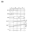
- FIG. 2 is a timing chart illustrating an operation example of the semiconductor device.
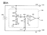
- 3A and 3B are diagrams showing an operation example of the semiconductor device.
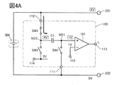
- 4A and 4B are diagrams showing an operation example of the semiconductor device.
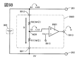
- 5A and 5B are diagrams showing a configuration example of a conventional semiconductor device.
- 6A to 6D are diagrams showing circuit symbols of transistors.
- FIG. 7 is a diagram showing a configuration example of a semiconductor device.
- FIG. 8 is a diagram showing a configuration example of a semiconductor device.
- FIG. 9 is a diagram showing a configuration example of a semiconductor device.
- FIG. 10 is a timing chart illustrating an operation example of the semiconductor device.
- FIG. 10 is a timing chart illustrating an operation example of the semiconductor device.
- FIG. 11 is a diagram showing an operation example of the semiconductor device.
- FIG. 12 is a diagram showing an operation example of the semiconductor device.
- FIG. 13 is a diagram showing an operation example of the semiconductor device.
- FIG. 14 is a diagram showing an operation example of the semiconductor device.
- 15A and 15B are diagrams showing a configuration example of a semiconductor device.
- FIG. 16 is a diagram showing a configuration example of a semiconductor device.
- FIG. 17 is a diagram showing a configuration example of a semiconductor device.
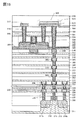
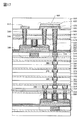
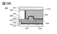
- 18A to 18C are diagrams showing a configuration example of a transistor.
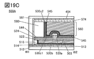
- 19A to 19C are diagrams showing a configuration example of a transistor.
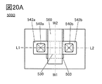
- 20A to 20C are diagrams showing a configuration example of a transistor.
- 21A to 21C are diagrams showing a configuration example of a secondary battery.
- 22A and 22B are diagrams showing a configuration example of the wound body and the secondary battery.
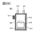
- 23A to 23C are diagrams showing a configuration example of the battery pack.
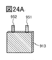
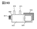
- 24A to 24D are views showing a configuration example of the battery pack.
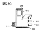
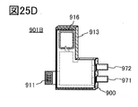
- 25A to 25D are views showing a configuration example of the battery pack.
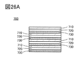
- 26A and 26B are diagrams showing a configuration example of the secondary battery.
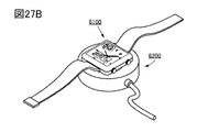
- 27A and 27B are diagrams showing an example of an electronic device.
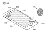
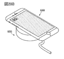
- 28A and 28B are diagrams showing an example of an electronic device.
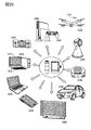
- FIG. 29 is a diagram showing an example of an electronic device.
- 30A to 30D are diagrams showing verification results of circuit operation.
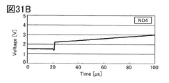
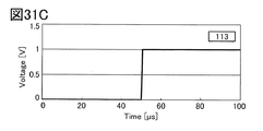
- 31A to 31D are diagrams showing verification results of circuit operation.
- the position, size, range, etc. of each configuration shown in the drawings and the like may not represent the actual position, size, range, etc. in order to facilitate understanding of the invention. Therefore, the disclosed invention is not necessarily limited to the position, size, range, etc. disclosed in the drawings and the like.
- the resist mask or the like may be unintentionally reduced due to a process such as etching, but it may not be reflected in the drawing for easy understanding.
- top view also referred to as “plan view”
- perspective view the description of some components may be omitted in order to make the drawing easier to understand.
- electrode and “wiring” in the present specification and the like do not functionally limit these components.
- an “electrode” may be used as part of a “wiring” and vice versa.
- the terms “electrode” and “wiring” include the case where a plurality of “electrodes” and “wiring” are integrally formed.
- the "terminal" in the electric circuit means a part where current input or output, voltage input or output, or signal reception or transmission is performed. Therefore, a part of the wiring or the electrode may function as a terminal.
- the terms “upper” and “lower” in the present specification and the like do not limit the positional relationship of the components to be directly above or directly below and to be in direct contact with each other.
- electrode B on the insulating layer A it is not necessary that the electrode B is formed in direct contact with the insulating layer A, and another configuration is formed between the insulating layer A and the electrode B. Do not exclude those that contain elements.
- source and drain functions are interchanged depending on operating conditions, such as when transistors with different polarities are used or when the direction of current changes during circuit operation, so which one is the source or drain is limited. Is difficult. Therefore, in the present specification, the terms source and drain can be used interchangeably.
- electrically connected includes a case of being directly connected and a case of being connected via "something having some electrical action".
- the "thing having some kind of electrical action” is not particularly limited as long as it enables the exchange of electric signals between the connection targets. Therefore, even when it is expressed as “electrically connected", in an actual circuit, there is a case where there is no physical connection part and only the wiring is extended.
- parallel means, for example, a state in which two straight lines are arranged at an angle of ⁇ 10 ° or more and 10 ° or less. Therefore, the case of ⁇ 5 ° or more and 5 ° or less is also included.
- vertical and orthogonal mean, for example, a state in which two straight lines are arranged at an angle of 80 ° or more and 100 ° or less. Therefore, the case of 85 ° or more and 95 ° or less is also included.
- the voltage often indicates the potential difference between a certain potential and a reference potential (for example, ground potential or source potential). Therefore, it is often possible to paraphrase voltage and potential. In the present specification and the like, voltage and potential can be paraphrased unless otherwise specified.
- ordinal numbers such as “first" and “second” in the present specification and the like are added to avoid confusion of the components, and do not indicate any order or order such as process order or stacking order. ..
- terms that do not have ordinal numbers in the present specification and the like may have ordinal numbers within the scope of claims in order to avoid confusion of components.
- different ordinal numbers may be added within the scope of claims.
- the ordinal numbers may be omitted in the scope of claims.
- the "on state” of the transistor means a state in which the source and drain of the transistor can be regarded as being electrically short-circuited (also referred to as “conduction state”).
- the “off state” of the transistor means a state in which the source and drain of the transistor can be regarded as being electrically cut off (also referred to as “non-conducting state”).
- the “on current” may mean a current flowing between the source and the drain when the transistor is in the on state.
- the “off current” may mean a current flowing between the source and the drain when the transistor is in the off state.
- the high power supply potential VDD (hereinafter, also simply referred to as “VDD”, “H potential”, or “H”) indicates a power supply potential having a potential higher than that of the low power supply potential VSS.
- the low power supply potential VSS (hereinafter, also simply referred to as “VSS”, “L potential”, or “L”) indicates a power supply potential having a potential lower than that of the high power supply potential VDD.
- the ground potential can also be used as VDD or VSS. For example, when VDD is the ground potential, VSS is a potential lower than the ground potential, and when VSS is the ground potential, VDD is a potential higher than the ground potential.
- the gate means a part or all of the gate electrode and the gate wiring.
- the gate wiring refers to wiring for electrically connecting the gate electrode of at least one transistor with another electrode or another wiring.
- the source means a part or all of a source region, a source electrode, and a source wiring.
- the source region refers to a region of the semiconductor layer in which the resistivity is equal to or less than a certain value.
- the source electrode refers to a conductive layer in a portion connected to the source region.
- the source wiring is a wiring for electrically connecting the source electrode of at least one transistor to another electrode or another wiring.
- the drain means a part or all of the drain region, the drain electrode, and the drain wiring.
- the drain region refers to a region of the semiconductor layer in which the resistivity is equal to or less than a certain value.
- the drain electrode refers to a conductive layer at a portion connected to the drain region.
- Drain wiring refers to wiring for electrically connecting the drain electrode of at least one transistor to another electrode or another wiring.
- H indicating the H potential
- L indicating the L potential
- “H” or “L” may be added with enclosing characters to the wiring and electrodes where the potential change has occurred.
- an “x” symbol may be added over the transistor.
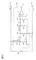
- ⁇ Voltage detection circuit 9900> First, a conventional example of a semiconductor device will be described. As a conventional example of the semiconductor device, a configuration example of the voltage detection circuit 9900 using the resistance voltage divider shown in FIG. 5A will be described.
- the voltage detection circuit 9900 has a resistor R1, a resistor R2, and a comparator 9901 (comparison circuit).
- the resistor R1 is provided between the terminal 9911 and the node ND9, and the resistor R2 is provided between the terminal 9912 and the node ND9. Further, the node ND 9 is electrically connected to the non-inverting input of the comparator 9901.
- the inverting input of the comparator 9901 is electrically connected to the terminal 9915, and the output of the comparator 9901 is electrically connected to the terminal 9913.
- the terminal 9912 is electrically connected to the terminal 201 and the positive electrode of the secondary battery 300.
- the terminal 9911 is electrically connected to the terminal 202 and the negative electrode of the secondary battery 300.
- the voltage detection circuit 9900 has a function of changing the voltage of the terminal 9913 from L to H when the voltage supplied to the secondary battery 300 via the terminals 201 and 202 exceeds a certain value.
- L is output when the voltage input to the non-inverting input is equal to or less than the voltage input to the inverting input, and the voltage input to the non-inverting input is input to the inverting input. It is assumed that H is output when the voltage exceeds the above voltage.
- the resistance value of the resistor R1 is 1 M ⁇
- the resistance value of the resistor R2 is 3 M ⁇
- the voltage of the terminal 9915 is 1.0 V
- the voltage of the node ND9 becomes 1.0V. That is, 1.0 V is supplied to the non-inverting input of the comparator 9901. Further, since 1.0 V is supplied to the inverting input of the comparator 9901 via the terminal 9915, L is output from the comparator 9901. Therefore, the voltage of the terminal 9913 becomes L.
- the voltage of the terminal 9912 exceeds 4.0 V
- the voltage of the node ND 9 also exceeds 1.0 V
- H is output from the comparator 9901. Therefore, the voltage of the terminal 9913 becomes H.
- the voltage of the terminal 9912 increases by 0.4V from 4.0V to 4.4V
- the voltage of the node ND9 increases by 0.1V from 1.0V to 1.1V.
- the voltage change amount of the node ND 9 is smaller than the voltage change amount of the terminal 9912, so that there is a problem that the detection sensitivity is low.
- ⁇ Voltage detection circuit 100> As an example of the semiconductor device according to one aspect of the present invention, a configuration example of the voltage detection circuit 100 will be described with reference to FIG. 1A.
- the voltage detection circuit 100 includes a switch SW1, a switch SW2, a switch SW3, a capacitance C1, and a comparator 101 (comparison circuit).
- One terminal of the switch SW1 is electrically connected to the terminal 111, and the other terminal is electrically connected to the node ND1.
- One terminal of the switch SW2 is electrically connected to the terminal 114, and the other terminal is electrically connected to the node ND2.
- One terminal of the switch SW3 is electrically connected to the node ND2, and the other terminal is electrically connected to the terminal 112.
- the capacitance C1 is provided between the node ND1 and the node ND2.
- the non-inverting input of the comparator 101 is electrically connected to the node ND1 and the inverting input is electrically connected to the terminal 115.
- the output of the comparator 101 is electrically connected to the terminal 113.
- the terminal 112 is electrically connected to the terminal 201 and the positive electrode of the secondary battery 300.
- the terminal 111 is electrically connected to the terminal 202 and the negative electrode of the secondary battery 300.
- the voltage detection circuit 100 has a function of changing the voltage of the terminal 113 from L to H when the voltage supplied to the secondary battery 300 via the terminals 201 and 202 exceeds a certain value.
- the switch means a switch that is in a conductive state (on state) or a non-conducting state (off state) and has a function of controlling whether or not a current flows.
- the switch means a switch having a function of selecting and switching a path through which a current flows.
- an electric switch, a mechanical switch, or the like can be used. That is, the switch is not limited to a specific switch as long as it can control the current.
- Examples of electrical switches include transistors (for example, bipolar transistors, MOS transistors, etc.), diodes (for example, PN diodes, PIN diodes, Schottky diodes, MIM (Metal Insulator Metal) diodes, and MIS (Metal Insulator Semiconductor) diodes. , Diode-connected transistors, etc.), or logic circuits that combine these.
- transistors for example, bipolar transistors, MOS transistors, etc.
- diodes for example, PN diodes, PIN diodes, Schottky diodes, MIM (Metal Insulator Metal) diodes, and MIS (Metal Insulator Semiconductor) diodes. , Diode-connected transistors, etc.
- the polarity (conductive type) of the transistor is not particularly limited.
- a mechanical switch is a switch that uses MEMS (Micro Electro Mechanical System) technology, such as the Digital Micromirror Device (DMD).
- MEMS Micro Electro Mechanical System
- DMD Digital Micromirror Device
- the switch has an electrode that can be moved mechanically, and the movement of the electrode controls conduction and non-conduction.
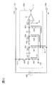
- FIG. 1B shows a configuration example of the voltage detection circuit 100T in which the switch SW1, the switch SW2, and the switch SW3 constituting the voltage detection circuit 100 are replaced with transistors.
- the voltage detection circuit 100T includes a transistor M1, a transistor M2, a transistor M3, a capacitance C1, and a comparator 101 (comparison circuit).
- One of the source or drain of the transistor M1 is electrically connected to the terminal 111, and the other of the source or drain is electrically connected to the node ND1.
- the gate of the transistor M1 is electrically connected to the terminal G1.
- One of the source or drain of the transistor M2 is electrically connected to the terminal 114, and the other of the source or drain is electrically connected to the node ND2.
- the gate of the transistor M2 is electrically connected to the terminal G2.
- One of the source or drain of the transistor M3 is electrically connected to the node ND2, and the other of the source or drain is electrically connected to the terminal 112.
- the gate of the transistor M3 is electrically connected to the terminal G3.
- the capacitance C1 is provided between the node ND1 and the node ND2.
- the non-inverting input of the comparator 101 is electrically connected to the node ND1 and the inverting input is electrically connected to the terminal 115.
- the output of the comparator 101 is electrically connected to the terminal 113.
- the transistor M1, the transistor M2, and the transistor M3 are preferably transistors (also referred to as "OS transistors") containing an oxide semiconductor which is a kind of metal oxide in the semiconductor layer on which the channel is formed. Since the oxide semiconductor has a band gap of 2 eV or more, the off-current is remarkably small. Therefore, the power consumption of the voltage detection circuit 100T can be reduced. Further, the power consumption of the semiconductor device including the voltage detection circuit 100T can be reduced. In particular, it is preferable to use an OS transistor for the transistor M1 because the charge supplied to the node ND1 can be retained for a long period of time.
- one of the source or drain of the transistor corresponds to one end (one terminal) of the switch, and the other of the source or drain of the transistor corresponds to the other end of the switch (the other terminal). To do.
- each of the transistor M1, the transistor M2, and the transistor M3 may be a double gate type transistor.
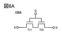
- FIG. 6A shows an example of a circuit symbol of the double gate type transistor 150A.
- the transistor 150A has a configuration in which the transistor Tr1 and the transistor Tr2 are connected in series.
- one of the source or drain of the transistor Tr1 is electrically connected to the terminal S
- the other of the source or drain of the transistor Tr1 is electrically connected to one of the source or drain of the transistor Tr2, and the source of the transistor Tr2.
- the other side of the drain is electrically connected to the terminal D.
- FIG. 6A shows a state in which the gates of the transistor Tr1 and the transistor Tr2 are electrically connected and are electrically connected to the terminal G.
- the transistor 150A shown in FIG. 6A has a function of switching between the terminal S and the terminal D in a conductive state or a non-conducting state by changing the potential of the terminal G. Therefore, the transistor 150A, which is a double-gate type transistor, functions as one transistor that contains the transistor Tr1 and the transistor Tr2. That is, in FIG. 6A, one of the source or drain of the transistor 150A is electrically connected to the terminal S, the other of the source or drain is electrically connected to the terminal D, and the gate is electrically connected to the terminal G. It can be said that there is.
- each of the transistor M1, the transistor M2, and the transistor M3 may be a triple gate type transistor.
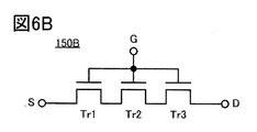
- FIG. 6B shows an example of a circuit symbol of the triple gate type transistor 150B.
- the transistor 150B has a configuration in which a transistor Tr1, a transistor Tr2, and a transistor Tr3 are connected in series.
- one of the source or drain of the transistor Tr1 is electrically connected to the terminal S
- the other of the source or drain of the transistor Tr1 is electrically connected to one of the source or drain of the transistor Tr2, and the source of the transistor Tr2.
- the other of the drains is electrically connected to one of the source or drain of the transistor Tr3, and the other of the source or drain of the transistor Tr3 is electrically connected to the terminal D.
- FIG. 6B shows a state in which the gates of the transistor Tr1, the transistor Tr2, and the transistor Tr3 are electrically connected and electrically connected to the terminal G.
- the transistor 150B shown in FIG. 6B has a function of switching between the terminal S and the terminal D in a conductive state or a non-conducting state by changing the potential of the terminal G. Therefore, the transistor 150B, which is a triple-gate type transistor, functions as one transistor including the transistor Tr1, the transistor Tr2, and the transistor Tr3. That is, in FIG. 6B, one of the source or drain of the transistor 150B is electrically connected to the terminal S, the other of the source or drain is electrically connected to the terminal D, and the gate is electrically connected to the terminal G. It can be said that there is.
- a transistor having a plurality of gates and to which the plurality of gates are electrically connected such as the transistor 150A and the transistor 150B, may be referred to as a "multi-gate type transistor” or a “multi-gate transistor”.
- each of the transistor M1, the transistor M2, and the transistor M3 may be a transistor having a back gate.
- FIG. 6C shows an example of a circuit symbol of the transistor 150C having a back gate.
- FIG. 6D shows an example of a circuit symbol of the transistor 150D having a back gate.
- the transistor 150C has a configuration in which a gate and a back gate are electrically connected.
- the transistor 150D has a configuration in which the back gate is electrically connected to the terminal BG.
- the back gate is arranged so as to sandwich the channel forming region of the semiconductor layer between the gate and the back gate.
- the back gate can function like a gate.
- the on-current of the transistor can be increased. Further, the threshold voltage of the transistor can be changed by independently changing the potential of the back gate.
- FIG. 2 is a timing chart illustrating the operation of the voltage detection circuit 100.
- 3 and 4 are diagrams showing an operating state of the voltage detection circuit 100.
- the potential of the terminal 113 in the charging operation of the secondary battery 300, the potential of the terminal 113 becomes L when the charging voltage is 4 V or less, and the potential of the terminal 113 becomes H when the charging voltage exceeds 4 V. To do. Further, it is assumed that 3V is supplied to the terminal 114 and 1V is supplied to the terminal 115. Further, it is assumed that the voltage of the terminal 201 changes from 3.5V to 4.4V during the charging operation.
- Period T1 During the period T1, the switch SW1 and the switch SW2 are turned on, and the switch SW3 is turned off (see FIG. 3A). Then, the voltage of the node ND1 becomes 0V, and the voltage of the node ND2 becomes 3V. 1V is input to the inverting input of the comparator 101, and 0V is input to the non-inverting input. Therefore, the output of the comparator 101 is L, and the voltage of the terminal 113 is also L.
- the voltage of the terminal 201 becomes 4V
- the voltage of the terminal 112 and the node ND2 also becomes 4V.
- the voltage of the node ND1 becomes 1V (see FIG. 4A). 1V is input to the inverting input of the comparator 101, and 1V is also input to the non-inverting input. Therefore, the output of the comparator 101 remains L, and the voltage of the terminal 113 also remains L.
- the voltage of the terminal 201 exceeds 4V
- the voltage of the terminal 112 and the node ND2 also exceeds 4V.
- the voltage of the node ND1 also exceeds 1V. 1V is input to the inverting input of the comparator 101, and a voltage exceeding 1V is input to the non-inverting input. Therefore, the output of the comparator 101 becomes H, and the voltage of the terminal 113 also becomes H.
- the voltage detection circuit 100 unlike the conventional voltage detection circuit 9900, no current It is generated during operation. Therefore, the power consumption can be reduced. Further, since the amount of voltage change between the terminal 112 and the node ND2 is equal, the detection sensitivity is good.
- the voltage detection circuit 100A will be described as a modification of the semiconductor device according to one aspect of the present invention.
- the voltage detection circuit 100A is a modification of the voltage detection circuit 100 shown in the above embodiment.
- FIG. 7 shows a configuration example of the voltage detection circuit 100A.
- the voltage detection circuit 100A has a configuration in which a switch SW4, a switch SW5, a switch SW6, and a capacitance C2 are added to the configuration of the voltage detection circuit 100.
- one terminal of the switch SW1 is electrically connected to the terminal 111, and the other terminal is electrically connected to the node ND1.
- One terminal of the switch SW2 is electrically connected to the terminal 114, and the other terminal is electrically connected to the node ND2.
- One terminal of the switch SW3 is electrically connected to the node ND2, and the other terminal is electrically connected to the terminal 112.
- One terminal of the switch SW4 is electrically connected to the terminal 111, and the other terminal is electrically connected to the node ND3.
- One terminal of the switch SW5 is electrically connected to the terminal 114, and the other terminal is electrically connected to the node ND4.
- One terminal of the switch SW6 is electrically connected to the node ND1, and the other terminal is electrically connected to the node ND4.
- the capacitance C1 is provided between the node ND1 and the node ND2.
- the capacity C2 is provided between the node ND3 and the node ND4.
- the non-inverting input of the comparator 101 is electrically connected to the node ND3, and the inverting input is electrically connected to the terminal 115.
- the output of the comparator 101 is electrically connected to the terminal 113.
- the terminal 112 is electrically connected to the terminal 201 and the positive electrode of the secondary battery 300.
- the terminal 111 is electrically connected to the terminal 202 and the negative electrode of the secondary battery 300.
- the voltage detection circuit 100A has a function of changing the voltage of the terminal 113 from L to H when the voltage supplied to the secondary battery 300 via the terminals 201 and 202 exceeds a certain value.
- FIG. 8 shows a voltage detection circuit 100B which is a modification of the voltage detection circuit 100A.
- the voltage detection circuit 100B has terminals 111A and 111B instead of terminals 111, and has terminals 114A and 114B instead of terminals 114.
- one terminal of the switch SW1 is electrically connected to the terminal 111A, and one terminal of the switch SW4 is electrically connected to the terminal 111B. Further, one terminal of the switch SW2 is electrically connected to the terminal 114A, and one terminal of the switch SW5 is electrically connected to the terminal 114B.
- both the terminal 111A and the terminal 111B are electrically connected to the terminal 202, but the terminal 111A and the terminal 111B may be electrically connected to different terminals or wirings.
- FIG. 9 shows a configuration example of the voltage detection circuit 100TA in which the switches SW1 to SW6 constituting the voltage detection circuit 100A are replaced with transistors.
- the voltage detection circuit 100TA is a modification of the voltage detection circuit 100T.
- the voltage detection circuit 100TA has a configuration in which a transistor M4, a transistor M5, a transistor M6, and a capacitance C2 are added to the configuration of the voltage detection circuit 100T.
- the voltage detection circuit 100TA includes a transistor M1, a transistor M2, a transistor M3, a transistor M4, a transistor M5, a transistor M6, a capacitance C1, a capacitance C2, and a comparator 101.
- One of the source or drain of the transistor M1 is electrically connected to the terminal 111, and the other of the source or drain is electrically connected to the node ND1.
- the gate of the transistor M1 is electrically connected to the terminal G1.
- One of the source or drain of the transistor M2 is electrically connected to the terminal 114, and the other of the source or drain is electrically connected to the node ND2.
- the gate of the transistor M2 is electrically connected to the terminal G2.
- One of the source or drain of the transistor M3 is electrically connected to the node ND2, and the other of the source or drain is electrically connected to the terminal 112.
- the gate of the transistor M3 is electrically connected to the terminal G3.
- One of the source or drain of the transistor M4 is electrically connected to the terminal 111, and the other of the source or drain is electrically connected to the node ND3.
- the gate of the transistor M4 is electrically connected to the terminal G4.
- One of the source or drain of the transistor M5 is electrically connected to the terminal 114, and the other of the source or drain is electrically connected to the node ND4.
- the gate of the transistor M5 is electrically connected to the terminal G5.
- One of the source or drain of the transistor M6 is electrically connected to the node ND1, and the other of the source or drain is electrically connected to the node ND4.
- the gate of the transistor M6 is electrically connected to the terminal G6.
- the capacitance C1 is provided between the node ND1 and the node ND2.
- the capacity C2 is provided between the node ND3 and the node ND4.
- the non-inverting input of the comparator 101 is electrically connected to the node ND3, and the inverting input is electrically connected to the terminal 115.
- the output of the comparator 101 is electrically connected to the terminal 113.
- the transistors M4 to M6 are preferably OS transistors.
- OS transistors it is preferable to use an OS transistor for the transistor M4 because the charge supplied to the node ND3 can be retained for a long period of time.
- OS transistor for the transistor M5 it is preferable to use an OS transistor for the transistor M5 because the charge supplied to the node ND4 can be retained for a long period of time.
- FIG. 10 is a timing chart illustrating the operation of the voltage detection circuit 100A.
- 11 to 14 are diagrams showing an operating state of the voltage detection circuit 100A.
- the potential of the terminal 113 becomes L when the charging voltage is 4 V or less, and the voltage of the terminal 113 becomes H when the charging voltage exceeds 4 V. To do. Further, it is assumed that 1.5 V is supplied to the terminal 114 and 1 V is supplied to the terminal 115. Further, it is assumed that the voltage of the terminal 201 changes from 3.5V to 4.4V during the charging operation.
- the voltage of the node ND3 becomes 0.5V, and 0.5V is input to the non-inverting input of the comparator 101. Since 1V is input to the inverting input of the comparator 101, the output of the comparator 101 remains L, and the voltage of the terminal 113 also remains L.
- the voltage of the terminal 201 rises, the voltage of the terminal 112 and the node ND2 also rises. Therefore, the voltages of the nodes ND1, the node ND3, and the node ND4 also increase.
- the voltage of the terminal 201 exceeds 4V
- the voltage of the terminal 112 and the node ND2 also exceeds 4V.
- the voltage of the node ND3 also exceeds 1V. 1V is input to the inverting input of the comparator 101, and a voltage exceeding 1V is input to the non-inverting input. Therefore, the output of the comparator 101 becomes H, and the voltage of the terminal 113 also becomes H.
- the voltage of the terminal 201 becomes 4.4V
- the voltage of the node ND2 also becomes 4.4V.
- the voltage of the node ND1 and the node ND4 becomes 2.9V
- the voltage of the node ND3 becomes 1.4V. (See FIG. 14).
- the voltage detection circuit 100A shown in the present embodiment can make the voltage applied to the terminal 114 smaller than that of the voltage detection circuit 100. Therefore, the power consumption can be reduced as compared with the voltage detection circuit 100. Further, since the voltage required for operation can be reduced, the load on the voltage generation circuit is reduced. Therefore, the operation of the semiconductor device using the voltage detection circuit 100A is stable and the reliability can be improved.
- a radio wave method As a method for realizing wireless power supply, a radio wave method, an electric field coupling method, a magnetic field resonance method, an electromagnetic induction method and the like are known.
- the electromagnetic induction method is known as a method with easy circuit design and high power transmission efficiency, and its adoption in mobile devices such as personal digital assistants is being considered.
- As international standards for wireless power supply using the electromagnetic induction method there are Qi standard, PMA standard, AirFuel Inductive standard and the like.
- the magnetic field resonance method has a more complicated circuit design and inferior power transmission efficiency than the electromagnetic induction method, but it can transmit power over a longer distance than the electromagnetic induction method, and is adopted for EV (Electric Vehicle) and the like. It is being considered.
- EV Electric Vehicle
- As international standards for wireless power supply using the magnetic field resonance method there are WPT1 standard, WPT2 standard, WPT3 standard, AirFuel Resonant standard and the like.
- the semiconductor device according to one aspect of the present invention can be used in various types of wireless power feeding systems. Further, the semiconductor device according to one aspect of the present invention can be used for wireless power feeding systems of various standards.
- the wireless power supply system exemplified in this embodiment includes a power transmission device 400 and a power reception device 450.
- a configuration example of the power transmission device 400 is shown in FIG. 15A.
- a configuration example of the power receiving device 450 is shown in FIG. 15B.
- the configuration of the power transmission device 400 illustrated in FIG. 15A and the power receiving device 450 illustrated in FIG. 15B is an example, and it is not necessary to include all the components.
- the power transmitting device 400 and the power receiving device 450 may have the necessary components among the components shown in FIGS. 15A and 15B. Further, it may have components other than the components shown in FIGS. 15A and 15B.
- the power transmission device 400 includes a power transmission control circuit 411, a matching circuit 412, and a power radiation circuit 413.
- a power source 401 is connected to the power transmission device 400.
- the power source 401 has a function of supplying AC power to the power transmission device 400.
- the frequency fG of the AC power supplied by the power supply 401 is not limited to a specific frequency, for example, 300 GHz to 3 THz which is a submillimeter wave, 30 GHz to 300 GHz which is a millimeter wave, 3 GHz to 30 GHz which is a microwave, and 300 MHz which is an ultra high frequency.
- any of ⁇ 3 GHz, ultra-short wave 30 MHz to 300 MHz, short wave 3 MHz to 30 MHz, medium wave 300 kHz to 3 MHz, long wave 30 kHz to 300 kHz, and ultra-long wave 3 kHz to 30 kHz can be used.
- the power transmission control circuit 411 has a function of supplying the electric power supplied from the power source 401 to the electric power radiation circuit 413 via the matching circuit 412.
- the power radiation circuit 413 is connected to the power transmission antenna 402.
- the power radiation circuit 413 has a function of radiating AC power supplied from the power source 401 to an external space via a power transmission antenna 402.
- the matching circuit 412 has a function of substantially matching the impedance of the power supply 401 and the impedance of the power radiation circuit 413 and efficiently transmitting the AC power supplied from the power supply 401 to the power radiation circuit 413.
- the power receiving device 450 shown in FIG. 15B includes a power receiving antenna 403, a power receiving circuit 451 and a charge control circuit 452, and a charge / discharge control circuit 453. Further, the power receiving device 450 has a terminal 461, a terminal 462, and a terminal 463. In FIG. 15B, the positive electrode of the secondary battery 300 is electrically connected to the terminal 461, and the negative electrode of the secondary battery 300 is electrically connected to the terminal 462.
- the power receiving circuit 451 has a resonance frequency fR determined based on the inductance of the power receiving antenna 403. By matching the frequency fG of the AC power radiated from the power transmitting antenna 402 with the resonance frequency fR of the power receiving circuit 451, an induced electromotive force is generated in the power receiving antenna 403, and power is supplied from the power transmitting device 400 to the power receiving device 450. It can be realized.
- the power receiving circuit 451 has a rectifier circuit.
- the rectifier circuit has a function of converting AC power induced in the power receiving antenna 403 into DC.
- the charge control circuit 452 has a function of adjusting the DC power supplied from the power receiving circuit 451 to an appropriate voltage. For example, a function such as a switching regulator may be added to the charge control circuit 452.
- Nonf-CPU (normally off CPU) may be used for the charge control circuit 452.
- the normally-off CPU is an integrated circuit including a normally-off type transistor that is in a non-conducting state (also referred to as an off state) even when the gate voltage is 0V.
- the normally-off type transistor can be realized by an OS transistor.
- the AC power induced in the power receiving antenna 403 can be charged to the secondary battery 300 via the power receiving circuit 451 and the charge control circuit 452.
- the power receiving device 450 can function as a power source for an external device. Specifically, by electrically connecting to an external device via the terminals 461 and 463, the power of the secondary battery can be supplied to the external device. In addition, the electric power received from the power transmission device 400 can be supplied to the external device.
- the charge / discharge control circuit 453 has a function of monitoring the charge / discharge status of the secondary battery 300.
- the charge / discharge control circuit 453 includes an overcurrent detection circuit, a voltage detection circuit, and the like. For example, when a current exceeding a specified value (also referred to as “overcurrent”) flows when power is supplied from the secondary battery 300 to an external device, the charge / discharge control circuit 453 turns off the transistor 471 to generate power. The supply can be stopped. Further, when a current of a specified value or more flows during charging of the secondary battery 300, the charge / discharge control circuit 453 can turn off the transistor 472 and stop charging. Further, when a voltage equal to or higher than a specified value (also referred to as “overvoltage”) is applied to the secondary battery 300 when charging the secondary battery 300, the charge / discharge control circuit 453 turns off the transistor 472 and stops charging. can do.
- a specified value also referred to as “overcurrent”
- the power transmitting antenna 402 shown in FIG. 15A and the power receiving antenna 403 shown in FIG. 15B are illustrated by circuit symbols indicating coils.
- the power transmission antenna 402 and the power reception antenna 403 are not limited to the coiled antenna, and may be appropriately changed depending on the power transmission method or the like. For example, it may be linear or plate-shaped. Further, antennas such as a flat antenna, an open surface antenna, a traveling wave antenna, an EH antenna, a magnetic field antenna, and a dielectric antenna may be used.
- the voltage detection circuit 100 can be used in the charge / discharge control circuit 453. Further, an OS transistor can be used for a part or all of the transistors included in the wireless power feeding system.
- the power receiving device 450 can be provided on the flexible substrate. Therefore, the volume and weight of the power receiving device 450 can be reduced. Further, by providing the power receiving device 450 on the flexible substrate, for example, it is possible to provide the power receiving device 450 along the side surface of the secondary battery 300.
- a charge / discharge control circuit using an OS transistor, an overcurrent detection circuit, a voltage detection circuit, an abnormality detection circuit, a secondary battery control system, or the like may be referred to as a BTOS (Battery operating system or Battery accessory semiconductor). is there.
- BTOS Battery operating system or Battery accessory semiconductor
- the OS transistor has a significantly small off current. Therefore, the power consumption of the wireless power supply system can be reduced.
- the off-current of the OS transistor hardly increases even in a high temperature environment. Specifically, the off-current hardly increases even at an ambient temperature of room temperature or higher and 200 ° C. or lower.
- the OS transistor has a high dielectric strength between the source and the drain.
- the semiconductor device shown in FIG. 16 has a transistor 550, a transistor 500, and a capacity of 600.
- 18A is a cross-sectional view of the transistor 500 in the channel length direction
- FIG. 18B is a cross-sectional view of the transistor 500 in the channel width direction
- FIG. 18C is a cross-sectional view of the transistor 550 in the channel width direction.
- the transistor 500 is an OS transistor. Therefore, since the transistor 500 has an extremely small off current, it is possible to retain the data voltage or electric charge written for a long period of time by using the transistor 500 for a transistor included in the semiconductor device. That is, since the frequency of the refresh operation is low or the refresh operation is not required, the power consumption of the semiconductor device can be reduced.
- the semiconductor device described in this embodiment has a transistor 550, a transistor 500, and a capacity of 600.
- the transistor 500 is provided above the transistor 550, and the capacitance 600 is provided above the transistor 550 and the transistor 500.
- the transistor 550 is provided on the substrate 311 and has a semiconductor region 313 composed of a conductor 316, an insulator 315, and a part of the substrate 311, a low resistance region 314a functioning as a source region or a drain region, and a low resistance region 314b. ..
- the transistor 550 can be applied to, for example, the transistor included in the comparator 101 in the above embodiment.
- the transistor 550 has a top surface of the semiconductor region 313 and a side surface in the channel width direction covered with a conductor 316 via an insulator 315.
- the transistor 550 By making the transistor 550 a Fin type in this way, the on-characteristics of the transistor 550 can be improved by increasing the effective channel width. Further, since the contribution of the electric field of the gate electrode can be increased, the off characteristic of the transistor 550 can be improved.
- the transistor 550 may be either a p-channel type or an n-channel type.
- a semiconductor such as a silicon-based semiconductor is included in a region in which a channel of the semiconductor region 313 is formed, a region in the vicinity thereof, a low resistance region 314a serving as a source region or a drain region, a low resistance region 314b, and the like. It preferably contains crystalline silicon. Alternatively, it may be formed of a material having Ge (germanium), SiGe (silicon germanium), GaAs (gallium arsenide), GaAlAs (gallium aluminum arsenide), or the like. A configuration using silicon in which the effective mass is controlled by applying stress to the crystal lattice and changing the lattice spacing may be used. Alternatively, the transistor 550 may be a HEMT (High Electron Mobility Transistor) by using GaAs, GaAlAs, or the like.
- HEMT High Electron Mobility Transistor
- the low resistance region 314a and the low resistance region 314b impart n-type conductivity-imparting elements such as arsenic and phosphorus, or p-type conductivity such as boron, in addition to the semiconductor material applied to the semiconductor region 313. Contains elements that
- the conductor 316 that functions as a gate electrode is a semiconductor material such as silicon, a metal material, or an alloy that contains an element that imparts n-type conductivity such as arsenic or phosphorus, or an element that imparts p-type conductivity such as boron.
- a material or a conductive material such as a metal oxide material can be used.
- the threshold voltage of the transistor can be adjusted by selecting the material of the conductor. Specifically, it is preferable to use a material such as titanium nitride or tantalum nitride for the conductor. Further, in order to achieve both conductivity and embedding property, it is preferable to use a metal material such as tungsten or aluminum as a laminate for the conductor, and it is particularly preferable to use tungsten in terms of heat resistance.
- the transistor 550 shown in FIG. 16 is an example, and the transistor is not limited to the configuration, and an appropriate transistor may be used according to the circuit configuration and the driving method.
- the configuration of the transistor 550 is an oxide semiconductor.
- the configuration may be the same as that of the transistor 500 used. The details of the transistor 500 will be described later.
- An insulator 320, an insulator 322, an insulator 324, and an insulator 326 are laminated in this order so as to cover the transistor 550.
- the insulator 320, the insulator 322, the insulator 324, and the insulator 326 for example, silicon oxide, silicon oxide, silicon nitride, silicon nitride, aluminum oxide, aluminum oxide, aluminum nitride, aluminum nitride and the like can be used. Just do it.
- silicon oxide refers to a material whose composition has a higher oxygen content than nitrogen
- silicon nitride refers to a material whose composition has a higher nitrogen content than oxygen. Is shown.
- aluminum nitride refers to a material whose composition has a higher oxygen content than nitrogen
- aluminum nitride refers to a material whose composition has a higher nitrogen content than oxygen. Is shown.
- the insulator 322 may have a function as a flattening film for flattening a step generated by a transistor 550 or the like provided below the insulator 322.
- the upper surface of the insulator 322 may be flattened by a flattening treatment using a chemical mechanical polishing (CMP) method or the like in order to improve the flatness.
- CMP chemical mechanical polishing
- the insulator 324 it is preferable to use a film having a barrier property so that hydrogen and impurities do not diffuse in the region where the transistor 500 is provided from the substrate 311 or the transistor 550.
- a film having a barrier property against hydrogen for example, silicon nitride formed by the CVD method can be used.
- hydrogen may diffuse into a semiconductor element having an oxide semiconductor such as a transistor 500, so that the characteristics of the semiconductor element may deteriorate. Therefore, it is preferable to use a film that suppresses the diffusion of hydrogen between the transistor 500 and the transistor 550.
- the membrane that suppresses the diffusion of hydrogen is a membrane that desorbs a small amount of hydrogen.
- the amount of hydrogen desorbed can be analyzed using, for example, a heated desorption gas analysis method (TDS).
- TDS heated desorption gas analysis method
- the amount of hydrogen desorbed from the insulator 324 is such that the amount desorbed in terms of hydrogen atoms is converted per area of the insulator 324 when the surface temperature of the film is in the range of 50 ° C. to 500 ° C. It may be 10 ⁇ 10 15 atoms / cm 2 or less, preferably 5 ⁇ 10 15 atoms / cm 2 or less.
- the insulator 326 preferably has a lower dielectric constant than the insulator 324.
- the relative permittivity of the insulator 326 is preferably less than 4, more preferably less than 3.
- the relative permittivity of the insulator 326 is preferably 0.7 times or less, more preferably 0.6 times or less, the relative permittivity of the insulator 324.
- the insulator 320, the insulator 322, the insulator 324, and the insulator 326 are embedded with a capacity of 600, a conductor 328 connected to the transistor 500, a conductor 330, and the like.
- the conductor 328 and the conductor 330 have a function as a plug or a wiring.
- a conductor having a function as a plug or a wiring may collectively give a plurality of configurations and give the same reference numeral.
- the wiring and the plug connected to the wiring may be integrated. That is, a part of the conductor may function as a wiring, and a part of the conductor may function as a plug.
- each plug and wiring As the material of each plug and wiring (conductor 328, conductor 330, etc.), a conductive material such as a metal material, an alloy material, a metal nitride material, or a metal oxide material is used as a single layer or laminated. be able to. It is preferable to use a refractory material such as tungsten or molybdenum that has both heat resistance and conductivity, and it is preferable to use tungsten. Alternatively, it is preferably formed of a low resistance conductive material such as aluminum or copper. Wiring resistance can be reduced by using a low resistance conductive material.
- a wiring layer may be provided on the insulator 326 and the conductor 330.
- the insulator 350, the insulator 352, and the insulator 354 are laminated in this order.
- a conductor 356 is formed on the insulator 350, the insulator 352, and the insulator 354.
- the conductor 356 has a function as a plug or wiring for connecting to the transistor 550.
- the conductor 356 can be provided by using the same materials as the conductor 328 and the conductor 330.
- the insulator 350 it is preferable to use an insulator having a barrier property against hydrogen, similarly to the insulator 324.
- the conductor 356 preferably contains a conductor having a barrier property against hydrogen.
- a conductor having a barrier property against hydrogen is formed in the opening of the insulator 350 having a barrier property against hydrogen.
- the conductor having a barrier property against hydrogen for example, tantalum nitride or the like may be used. Further, by laminating tantalum nitride and tungsten having high conductivity, it is possible to suppress the diffusion of hydrogen from the transistor 550 while maintaining the conductivity as wiring. In this case, it is preferable that the tantalum nitride layer having a barrier property against hydrogen is in contact with the insulator 350 having a barrier property against hydrogen.
- a wiring layer may be provided on the insulator 354 and the conductor 356.
- the insulator 360, the insulator 362, and the insulator 364 are laminated in this order.
- a conductor 366 is formed on the insulator 360, the insulator 362, and the insulator 364.
- the conductor 366 has a function as a plug or wiring.
- the conductor 366 can be provided by using the same materials as the conductor 328 and the conductor 330.
- the insulator 360 it is preferable to use an insulator having a barrier property against hydrogen, similarly to the insulator 324.
- the conductor 366 preferably contains a conductor having a barrier property against hydrogen.
- a conductor having a barrier property against hydrogen is formed in the opening of the insulator 360 having a barrier property against hydrogen.
- a wiring layer may be provided on the insulator 364 and the conductor 366.
- the insulator 370, the insulator 372, and the insulator 374 are laminated in this order.
- a conductor 376 is formed on the insulator 370, the insulator 372, and the insulator 374.
- the conductor 376 has a function as a plug or wiring.
- the conductor 376 can be provided by using the same material as the conductor 328 and the conductor 330.
- the insulator 370 it is preferable to use an insulator having a barrier property against hydrogen, similarly to the insulator 324.
- the conductor 376 preferably contains a conductor having a barrier property against hydrogen.
- a conductor having a barrier property against hydrogen is formed in the opening of the insulator 370 having a barrier property against hydrogen.
- a wiring layer may be provided on the insulator 374 and the conductor 376.
- the insulator 380, the insulator 382, and the insulator 384 are laminated in this order.
- a conductor 386 is formed on the insulator 380, the insulator 382, and the insulator 384.
- the conductor 386 has a function as a plug or wiring.
- the conductor 386 can be provided by using the same materials as the conductor 328 and the conductor 330.
- the insulator 380 it is preferable to use an insulator having a barrier property against hydrogen, similarly to the insulator 324.
- the conductor 386 preferably contains a conductor having a barrier property against hydrogen.
- a conductor having a barrier property against hydrogen is formed in the opening of the insulator 380 having a barrier property against hydrogen.
- the semiconductor device according to the present embodiment has been described. It is not limited to this.
- the number of wiring layers similar to the wiring layer including the conductor 356 may be 3 or less, or the number of wiring layers similar to the wiring layer including the conductor 356 may be 5 or more.
- the insulator 510, the insulator 512, the insulator 514, and the insulator 516 are laminated in this order.
- the insulator 510, the insulator 512, the insulator 514, and the insulator 516 it is preferable to use a substance having a barrier property against oxygen and hydrogen.
- a film having a barrier property such that hydrogen and impurities do not diffuse from the region where the substrate 311 or the transistor 550 is provided to the region where the transistor 500 is provided is used. Is preferable. Therefore, the same material as the insulator 324 can be used.
- Silicon nitride formed by the CVD method can be used as an example of a film having a barrier property against hydrogen.
- hydrogen may diffuse into a semiconductor element having an oxide semiconductor such as a transistor 500, so that the characteristics of the semiconductor element may deteriorate. Therefore, it is preferable to use a film that suppresses the diffusion of hydrogen between the transistor 500 and the transistor 550.
- the membrane that suppresses the diffusion of hydrogen is a membrane that desorbs a small amount of hydrogen.
- the film having a barrier property against hydrogen for example, it is preferable to use metal oxides such as aluminum oxide, hafnium oxide, and tantalum oxide for the insulator 510 and the insulator 514.
- metal oxides such as aluminum oxide, hafnium oxide, and tantalum oxide for the insulator 510 and the insulator 514.
- aluminum oxide has a high blocking effect that does not allow the membrane to permeate both oxygen and impurities such as hydrogen and water that cause fluctuations in the electrical characteristics of the transistor. Therefore, aluminum oxide can prevent impurities such as hydrogen and moisture from being mixed into the transistor 500 during and after the manufacturing process of the transistor. In addition, the release of oxygen from the oxides constituting the transistor 500 can be suppressed. Therefore, it is suitable for use as a protective film for the transistor 500.
- the same material as that of the insulator 320 can be used for the insulator 512 and the insulator 516. Further, by applying a material having a relatively low dielectric constant to these insulators, it is possible to reduce the parasitic capacitance generated between the wirings.
- a silicon oxide film, a silicon nitride film, or the like can be used as the insulator 512 and the insulator 516.
- a conductor 518 a conductor constituting the transistor 500 (for example, a conductor 503) and the like are embedded.
- the conductor 518 has a capacity of 600, or a function as a plug or wiring for connecting to the transistor 550.
- the conductor 518 can be provided by using the same material as the conductor 328 and the conductor 330.
- the conductor 510 in the region in contact with the insulator 510 and the insulator 514 is preferably a conductor having a barrier property against oxygen, hydrogen, and water.
- the transistor 550 and the transistor 500 can be separated by a layer having a barrier property against oxygen, hydrogen, and water, and the diffusion of hydrogen from the transistor 550 to the transistor 500 can be suppressed.
- a transistor 500 is provided above the insulator 516.
- the transistor 500 consists of a conductor 503 arranged so as to be embedded in the insulator 514 and the insulator 516, and an insulator 520 arranged on the insulator 516 and the insulator 503. And on the insulator 522 placed on the insulator 520, the insulator 524 placed on the insulator 522, the oxide 530a placed on the insulator 524, and the oxide 530a.
- the arranged oxide 530b, the conductors 542a and 542b arranged apart from each other on the oxide 530b, the conductors 542a and the conductors 542b, and between the conductors 542a and 542b.
- the insulator 544 is arranged between the oxide 530a, the oxide 530b, the conductor 542a, and the conductor 542b and the insulator 580.
- the conductor 560 includes a conductor 560a provided inside the insulator 545 and a conductor 560b provided so as to be embedded inside the conductor 560a. It is preferable to have.
- the insulator 574 is arranged on the insulator 580, the conductor 560, and the insulator 545.
- oxide 530a, oxide 530b, and oxide 530c may be collectively referred to as oxide 530.
- the transistor 500 a configuration in which three layers of oxide 530a, oxide 530b, and oxide 530c are laminated is shown in a region where a channel is formed and in the vicinity thereof, but the present invention is limited to this. It's not a thing.
- a single layer of oxide 530b, a two-layer structure of oxide 530b and oxide 530a, a two-layer structure of oxide 530b and oxide 530c, or a laminated structure of four or more layers may be provided.
- the conductor 560 is shown as a two-layer laminated structure, but the present invention is not limited to this.
- the conductor 560 may have a single-layer structure or a laminated structure of three or more layers.
- the transistor 500 shown in FIGS. 16 and 18A is an example, and the transistor 500 is not limited to the configuration, and an appropriate transistor may be used according to the circuit configuration and the driving method.
- the conductor 560 functions as a gate electrode of the transistor, and the conductor 542a and the conductor 542b function as a source electrode or a drain electrode, respectively.
- the conductor 560 is formed so as to be embedded in the opening of the insulator 580 and the region sandwiched between the conductor 542a and the conductor 542b.
- the arrangement of the conductor 560, the conductor 542a and the conductor 542b is self-aligned with respect to the opening of the insulator 580. That is, in the transistor 500, the gate electrode can be arranged in a self-aligned manner between the source electrode and the drain electrode. Therefore, since the conductor 560 can be formed without providing the alignment margin, the occupied area of the transistor 500 can be reduced. As a result, the semiconductor device can be miniaturized and highly integrated.
- the conductor 560 is formed in a region between the conductor 542a and the conductor 542b in a self-aligned manner, the conductor 560 does not have a region that overlaps with the conductor 542a or the conductor 542b. Thereby, the parasitic capacitance formed between the conductor 560 and the conductors 542a and 542b can be reduced. Therefore, the switching speed of the transistor 500 can be improved and a high frequency characteristic can be provided.
- the conductor 560 may function as a first gate (also referred to as a top gate) electrode. Further, the conductor 503 may function as a second gate (also referred to as a bottom gate) electrode.
- the threshold voltage of the transistor 500 can be controlled by changing the potential applied to the conductor 503 independently of the potential applied to the conductor 560 without interlocking with it. In particular, by applying a negative potential to the conductor 503, the threshold voltage of the transistor 500 can be made larger than 0 V, and the off-current can be reduced. Therefore, when a negative potential is applied to the conductor 503, the drain current when the potential applied to the conductor 560 is 0 V can be made smaller than when it is not applied.
- the conductor 503 is arranged so as to overlap the oxide 530 and the conductor 560. As a result, when a potential is applied to the conductor 560 and the conductor 503, the electric field generated from the conductor 560 and the electric field generated from the conductor 503 are connected to cover the channel forming region formed in the oxide 530. Can be done.
- the configuration of the transistor that electrically surrounds the channel formation region by the electric field of the pair of gate electrodes is referred to as a surroundd channel (S-channel) configuration.
- S-channel the configuration of the transistor that electrically surrounds the channel formation region by the electric field of the pair of gate electrodes
- the side surface and the periphery of the oxide 530 in contact with the conductor 542a and the conductor 542b functioning as the source electrode and the drain electrode are the same as the channel forming region. It has the characteristic of being a mold.
- the side surface and the periphery of the oxide 530 in contact with the conductor 542a and the conductor 542b are in contact with the insulator 544, it can be type I as in the channel forming region.
- type I can be treated as the same as high-purity authenticity described later.
- the S-channel configuration disclosed in the present specification and the like is different from the Fin type configuration and the planar type configuration. By adopting the S-channel configuration, it is possible to increase the resistance to the short-channel effect, in other words, to make a transistor in which the short-channel effect is unlikely to occur.
- the conductor 503 has the same structure as the conductor 518, and the conductor 503a is formed in contact with the inner walls of the openings of the insulator 514 and the insulator 516, and the conductor 503b is further formed inside.
- the transistor 500 shows a configuration in which the conductor 503a and the conductor 503b are laminated, but the present invention is not limited to this.
- the conductor 503 may be provided as a single layer or a laminated structure having three or more layers.
- the conductor 503a it is preferable to use a conductive material having a function of suppressing the diffusion of impurities such as hydrogen atoms, hydrogen molecules, water molecules, and copper atoms (the above impurities are difficult to permeate).
- a conductive material having a function of suppressing the diffusion of oxygen for example, at least one oxygen atom, oxygen molecule, etc.
- the function of suppressing the diffusion of impurities or oxygen is a function of suppressing the diffusion of any one or all of the above impurities or the above oxygen.
- the conductor 503a since the conductor 503a has a function of suppressing the diffusion of oxygen, it is possible to prevent the conductor 503b from being oxidized and the conductivity from being lowered.
- the conductor 503 When the conductor 503 also functions as a wiring, it is preferable to use a highly conductive conductive material containing tungsten, copper, or aluminum as a main component for the conductor 503b.
- the conductor 503 is shown by laminating the conductor 503a and the conductor 503b, but the conductor 503 may have a single-layer structure.
- the insulator 520, the insulator 522, and the insulator 524 have a function as a second gate insulating film.
- the insulator 524 in contact with the oxide 530 it is preferable to use an insulator containing more oxygen than oxygen satisfying the stoichiometric composition. That is, it is preferable that the insulator 524 is formed with an excess oxygen region.
- oxygen vacancies in the oxide 530 V O: oxygen vacancy also called
- the defective hereinafter sometimes referred to as V O H.
- the defective Functions as a donor, sometimes electrons serving as carriers are generated.
- a part of hydrogen may be combined with oxygen that is bonded to a metal atom to generate an electron as a carrier. Therefore, a transistor using an oxide semiconductor containing a large amount of hydrogen tends to have a normally-on characteristic. Further, since hydrogen in the oxide semiconductor easily moves due to stress such as heat and electric field, if the oxide semiconductor contains a large amount of hydrogen, the reliability of the transistor may deteriorate. In one aspect of the present invention to reduce as much as possible V O H in the oxide 530, it is preferable that the highly purified intrinsic or substantially highly purified intrinsic.
- the V O H to obtain a sufficiently reduced oxide semiconductor the moisture in the oxide semiconductor, to remove impurities such as hydrogen (dehydration, may be described as dehydrogenation.) It is important to supply oxygen to the oxide semiconductor to compensate for the oxygen deficiency (sometimes referred to as dehydrogenation treatment).
- the V O H oxide semiconductor impurity is sufficiently reduced such by using a channel formation region of the transistor, it is possible to have stable electrical characteristics.
- an oxide material in which a part of oxygen is desorbed by heating is 1.0 ⁇ 10 18 atoms / cm 3 or more, preferably 1 in TDS (Thermal Desorption Spectroscopy) analysis.
- the surface temperature of the film during the TDS analysis is preferably in the range of 100 ° C. or higher and 700 ° C. or lower, or 100 ° C. or higher and 400 ° C. or lower.
- the insulator having the excess oxygen region and the oxide 530 may be brought into contact with each other to perform one or more of heat treatment, microwave treatment, or RF treatment.
- heat treatment microwave treatment, or RF treatment.
- water or hydrogen in the oxide 530 can be removed.
- reactions occur which bonds VoH is disconnected, when other words happening reaction of "V O H ⁇ Vo + H", it can be dehydrogenated.
- the hydrogen generated as oxygen combines with H 2 O, it may be removed from the oxide 530 or oxide 530 near the insulator.
- a part of hydrogen may be gettered on the conductor 542.
- the microwave processing for example, it is preferable to use an apparatus having a power source for generating high-density plasma or an apparatus having a power source for applying RF to the substrate side.
- an apparatus having a power source for generating high-density plasma for example, by using a gas containing oxygen and using a high-density plasma, high-density oxygen radicals can be generated, and by applying RF to the substrate side, the oxygen radicals generated by the high-density plasma can be generated.
- the pressure may be 133 Pa or more, preferably 200 Pa or more, and more preferably 400 Pa or more.
- oxygen and argon are used as the gas to be introduced into the apparatus for performing microwave treatment, and the oxygen flow rate ratio (O 2 / (O 2 + Ar)) is 50% or less, preferably 10% or more and 30. It is recommended to use less than%.
- the heat treatment may be performed, for example, at 100 ° C. or higher and 450 ° C. or lower, more preferably 350 ° C. or higher and 400 ° C. or lower.
- the heat treatment is carried out in an atmosphere of nitrogen gas or an inert gas, or an atmosphere containing 10 ppm or more, 1% or more, or 10% or more of an oxidizing gas.
- the heat treatment is preferably performed in an oxygen atmosphere.
- oxygen can be supplied to the oxide 530 to reduce oxygen deficiency ( VO ).
- the heat treatment may be performed in a reduced pressure state.
- the heat treatment may be carried out in an atmosphere containing 10 ppm or more, 1% or more, or 10% or more of oxidizing gas in order to supplement the desorbed oxygen after the heat treatment in an atmosphere of nitrogen gas or an inert gas.
- the heat treatment may be performed in an atmosphere containing 10 ppm or more, 1% or more, or 10% or more of the oxidizing gas, and then the heat treatment may be continuously performed in an atmosphere of nitrogen gas or an inert gas.
- the oxygen deficiency in the oxide 530 can be repaired by the supplied oxygen, in other words, the reaction "Vo + O ⁇ null" can be promoted. Further, since the oxygen supplied to the hydrogen remaining in the oxide 530 is reacted to remove the hydrogen as H 2 O (to dehydration) can. Thus, the hydrogen remained in the oxide 530 can be prevented from recombine V O H is formed by oxygen vacancies.
- the insulator 524 has an excess oxygen region, it is preferable that the insulator 522 has a function of suppressing the diffusion of oxygen (for example, oxygen atom, oxygen molecule, etc.) (the oxygen is difficult to permeate).
- oxygen for example, oxygen atom, oxygen molecule, etc.
- the insulator 522 has a function of suppressing the diffusion of oxygen and impurities, the oxygen contained in the oxide 530 does not diffuse to the insulator 520 side, which is preferable. Further, it is possible to suppress the conductor 503 from reacting with the oxygen contained in the insulator 524 and the oxide 530.
- the insulator 522 may be, for example, aluminum oxide, hafnium oxide, an oxide containing aluminum and hafnium (hafnium aluminate), tantalum oxide, zirconium oxide, lead zirconate titanate (PZT), strontium titanate (SrTIO 3 ), or It is preferable to use an insulator containing a so-called high-k material such as (Ba, Sr) TiO 3 (BST) in a single layer or in a laminated manner. As the miniaturization and high integration of transistors progress, problems such as leakage current may occur due to the thinning of the gate insulating film. By using a high-k material for the insulator that functions as a gate insulating film, it is possible to reduce the gate potential during transistor operation while maintaining the physical film thickness.
- a so-called high-k material such as (Ba, Sr) TiO 3 (BST)
- an insulator containing an oxide of one or both of aluminum and hafnium which are insulating materials having a function of suppressing diffusion of impurities and oxygen (the above-mentioned oxygen is difficult to permeate).
- the insulator containing one or both oxides of aluminum and hafnium it is preferable to use aluminum oxide, hafnium oxide, an oxide containing aluminum and hafnium (hafnium aluminate) and the like.
- the insulator 522 is formed by using such a material, the insulator 522 suppresses the release of oxygen from the oxide 530 and the mixing of impurities such as hydrogen from the peripheral portion of the transistor 500 into the oxide 530. Acts as a layer.
- aluminum oxide, bismuth oxide, germanium oxide, niobium oxide, silicon oxide, titanium oxide, tungsten oxide, yttrium oxide, and zirconium oxide may be added to these insulators.
- these insulators may be nitrided. Silicon oxide, silicon oxide or silicon nitride may be laminated on the above insulator.
- the insulator 520 is preferably thermally stable.
- silicon oxide and silicon oxide nitride are suitable because they are thermally stable.
- by combining the insulator of the high-k material with silicon oxide or silicon oxide nitride it is possible to obtain an insulator 520 having a laminated structure that is thermally stable and has a high relative permittivity.
- the insulator 520, the insulator 522, and the insulator 524 are shown as the second gate insulating film having a three-layer laminated structure, but the second gate.
- the insulating film may have a single layer, two layers, or a laminated structure of four or more layers. In that case, the laminated structure is not limited to the same material, and may be a laminated structure made of different materials.
- oxide 530 a metal oxide that functions as an oxide semiconductor for the oxide 530 containing the channel forming region.
- oxide 530 In-M-Zn oxide (element M is aluminum, gallium, yttrium, copper, vanadium, beryllium, boron, titanium, iron, nickel, germanium, zirconium, molybdenum, lantern, cerium, neodymium). , Hafnium, tantalum, tungsten, magnesium, etc. (one or more) and the like may be used.
- the In-M-Zn oxide that can be applied as the oxide 530 is preferably CAAC-OS (c-axis aligned crystalline oxide semiconductor).
- CAC-OS Cloud-Aligned Complex oxide semiconductor
- CAAC represents an example of crystal structure
- CAC represents an example of function or material structure.
- CAC-OS may be called CAC-metal oxide.
- the CAC-OS or CAC-metal oxide has a conductive function in a part of the material and an insulating function in a part of the material, and has a function as a semiconductor in the whole material.
- the conductive function is the function of flowing electrons (or holes) that become carriers
- the insulating function is the carrier. It is a function that does not allow electrons to flow.
- a switching function on / off function
- CAC-OS or CAC-metal oxide by separating each function, both functions can be maximized.
- CAC-OS or CAC-metal oxide has a conductive region and an insulating region.
- the conductive region has the above-mentioned conductive function
- the insulating region has the above-mentioned insulating function.
- the conductive region and the insulating region may be separated at the nanoparticle level. Further, the conductive region and the insulating region may be unevenly distributed in the material. In addition, the conductive region may be observed with the periphery blurred and connected in a cloud shape.
- CAC-OS or CAC-metal oxide when the conductive region and the insulating region are dispersed in the material in a size of 0.5 nm or more and 10 nm or less, preferably 0.5 nm or more and 3 nm or less, respectively. There is.
- CAC-OS or CAC-metal oxide is composed of components having different band gaps.
- CAC-OS or CAC-metal oxide is composed of a component having a wide gap due to an insulating region and a component having a narrow gap due to a conductive region.
- the carriers when the carriers flow, the carriers mainly flow in the components having a narrow gap.
- the component having a narrow gap acts complementarily to the component having a wide gap, and the carrier flows to the component having a wide gap in conjunction with the component having a narrow gap. Therefore, when the CAC-OS or CAC-metal oxide is used in the channel formation region of the transistor, a high current driving force, that is, a large on-current and a high field effect mobility can be obtained in the on-state of the transistor.
- CAC-OS or CAC-metal oxide can also be referred to as a matrix composite material (matrix composite) or a metal matrix composite material (metal matrix composite).
- the metal oxide that functions as an oxide semiconductor is divided into a single crystal oxide semiconductor and other non-single crystal oxide semiconductors.
- the non-monocrystalline oxide semiconductor include CAAC-OS, polycrystalline oxide semiconductor, nc-OS (nanocrystalline oxide semiconductor), pseudo-amorphous oxide semiconductor (a-like OS: amorphous-like oxide semiconductor), and the like. And amorphous oxide semiconductors.
- CAAC-OS has a c-axis orientation and has a distorted crystal structure in which a plurality of nanocrystals are connected in the ab plane direction.
- the strain refers to a region in which a plurality of nanocrystals are connected, in which the orientation of the lattice arrangement changes between a region in which the lattice arrangement is aligned and a region in which another lattice arrangement is aligned.
- nanocrystals are basically hexagonal, they are not limited to regular hexagons and may have non-regular hexagons. In addition, it may have a lattice arrangement such as a pentagon and a heptagon in distortion.
- a lattice arrangement such as a pentagon and a heptagon in distortion.
- CAAC-OS it is difficult to confirm a clear grain boundary (also referred to as grain boundary) even in the vicinity of strain. That is, it can be seen that the formation of grain boundaries is suppressed by the distortion of the lattice arrangement. This is because the CAAC-OS can tolerate distortion because the arrangement of oxygen atoms is not dense in the ab plane direction and the bond distance between atoms changes due to the substitution of metal elements. Because.
- CAAC-OS is a layered crystal in which a layer having indium and oxygen (hereinafter, In layer) and a layer having elements M, zinc, and oxygen (hereinafter, (M, Zn) layer) are laminated. It tends to have a structure (also called a layered structure). Indium and the element M can be replaced with each other, and when the element M of the (M, Zn) layer is replaced with indium, it can be expressed as the (In, M, Zn) layer. Further, when the indium of the In layer is replaced with the element M, it can be expressed as the (In, M) layer.
- CAAC-OS is a highly crystalline metal oxide.
- CAAC-OS it is difficult to confirm a clear grain boundary, so it can be said that a decrease in electron mobility due to the crystal grain boundary is unlikely to occur.
- CAAC-OS since the crystallinity of the metal oxide may be lowered due to the mixing of impurities or the formation of defects, CAAC-OS can be said to be a metal oxide having few impurities and defects (oxygen deficiency, etc.). Therefore, the metal oxide having CAAC-OS has stable physical properties. Therefore, the metal oxide having CAAC-OS is resistant to heat and has high reliability.
- the nc-OS has periodicity in the atomic arrangement in a minute region (for example, a region of 1 nm or more and 10 nm or less, particularly a region of 1 nm or more and 3 nm or less).
- nc-OS does not show regularity in crystal orientation between different nanocrystals. Therefore, no orientation is observed in the entire film. Therefore, nc-OS may be indistinguishable from a-like OS and amorphous oxide semiconductors depending on the analysis method.
- In-Ga-Zn oxide (also referred to as "IGZO"), which is a kind of metal oxide having indium, gallium, and zinc, has a stable structure by forming the above-mentioned nanocrystals. May be taken.
- IGZO tends to have difficulty in crystal growth in the atmosphere, it is preferable to use smaller crystals (for example, the above-mentioned nanocrystals) than large crystals (here, a few mm crystal or a few cm crystal). However, it may be structurally stable.
- the a-like OS is a metal oxide having a configuration between nc-OS and an amorphous oxide semiconductor.
- the a-like OS has a void or low density region. That is, the a-like OS has lower crystallinity than the nc-OS and CAAC-OS.
- Oxide semiconductors have various configurations, and each has different characteristics.
- the oxide semiconductor of one aspect of the present invention may have two or more of amorphous oxide semiconductor, polycrystalline oxide semiconductor, a-like OS, nc-OS, and CAAC-OS.
- a metal oxide having a low carrier concentration for the transistor 500 it is preferable to use a metal oxide having a low carrier concentration for the transistor 500.
- the impurity concentration in the metal oxide may be lowered to lower the defect level density.
- a low impurity concentration and a low defect level density is referred to as high-purity intrinsic or substantially high-purity intrinsic.
- impurities in the metal oxide include hydrogen, nitrogen, alkali metal, alkaline earth metal, iron, nickel, silicon and the like.
- hydrogen contained in a metal oxide reacts with oxygen bonded to a metal atom to form water, which may form an oxygen deficiency in the metal oxide. If the channel forming region in the metal oxide contains oxygen deficiency, the transistor may have a normally-on characteristic.
- a defect containing hydrogen in an oxygen deficiency may function as a donor and generate electrons as carriers.
- a part of hydrogen may be combined with oxygen that is bonded to a metal atom to generate an electron as a carrier. Therefore, a transistor using a metal oxide containing a large amount of hydrogen tends to have a normally-on characteristic.
- Defects containing hydrogen in oxygen deficiencies can function as donors for metal oxides. However, it is difficult to quantitatively evaluate the defect. Therefore, in the case of metal oxides, the carrier concentration may be used instead of the donor concentration. Therefore, in the present specification and the like, as a parameter of the metal oxide, a carrier concentration assuming a state in which an electric field is not applied may be used instead of the donor concentration. That is, the "carrier concentration" described in the present specification and the like may be paraphrased as the "donor concentration".
- the hydrogen concentration obtained by secondary ion mass spectrometry is less than 1 ⁇ 10 20 atoms / cm 3 , preferably 1 ⁇ 10 19 atoms / cm. It is less than 3 , more preferably less than 5 ⁇ 10 18 atoms / cm 3 , and even more preferably less than 1 ⁇ 10 18 atoms / cm 3 .
- the carrier concentration of the metal oxide in the channel formation region is preferably 1 ⁇ 10 18 cm -3 or less, and preferably less than 1 ⁇ 10 17 cm -3. Is more preferably less than 1 ⁇ 10 16 cm -3 , even more preferably less than 1 ⁇ 10 13 cm -3 , even more preferably less than 1 ⁇ 10 12 cm -3 .
- the lower limit of the carrier concentration of the metal oxide in the channel formation region is not particularly limited, but may be, for example, 1 ⁇ 10 -9 cm -3 .
- the oxygen in the oxide 530 diffuses to the conductor 542 when the conductor 542 (conductor 542a and the conductor 542b) and the oxide 530 come into contact with each other.
- the conductor 542 may oxidize. It is highly probable that the conductivity of the conductor 542 will decrease due to the oxidation of the conductor 542.
- the diffusion of oxygen in the oxide 530 into the conductor 542 can be rephrased as the conductor 542 absorbing the oxygen in the oxide 530.
- oxygen in the oxide 530 diffuses into the conductor 542 (conductor 542a and the conductor 542b), so that the oxygen in the oxide 530 diffuses between the conductor 542a and the oxide 530b, and the conductor 542b and the oxide 530b.
- Different layers may be formed between them. Since the different layer contains more oxygen than the conductor 542, it is presumed that the different layer has an insulating property.
- the three-layer structure of the conductor 542, the different layer, and the oxide 530b can be regarded as a three-layer structure composed of a metal, an insulator, and a semiconductor, and has a MIS (Metal-Insulator-Semiconductor) structure. It may be called, or it may be called a diode junction configuration mainly composed of a MIS configuration.
- the different layer is not limited to being formed between the conductor 542 and the oxide 530b.
- the different layer is formed between the conductor 542 and the oxide 530c, or when the different layer is conductive. It may be formed between the body 542 and the oxide 530b, and between the conductor 542 and the oxide 530c.
- a metal oxide having a band gap of 2 eV or more, preferably 2.5 eV or more, which functions as a channel forming region in the oxide 530 it is preferable to use a metal oxide having a band gap of 2 eV or more, preferably 2.5 eV or more, which functions as a channel forming region in the oxide 530. As described above, by using a metal oxide having a large bandgap, the off-current of the transistor can be reduced.
- the oxide 530 can suppress the diffusion of impurities from the composition formed below the oxide 530a to the oxide 530b. Further, by having the oxide 530c on the oxide 530b, it is possible to suppress the diffusion of impurities into the oxide 530b from the composition formed above the oxide 530c.
- the oxide 530 preferably has a laminated structure of a plurality of oxide layers having different atomic number ratios of each metal atom. Specifically, in the metal oxide used for the oxide 530a, the atomic number ratio of the element M in the constituent elements is larger than the atomic number ratio of the element M in the constituent elements in the metal oxide used in the oxide 530b. Is preferable. Further, in the metal oxide used for the oxide 530a, the atomic number ratio of the element M to In is preferably larger than the atomic number ratio of the element M to In in the metal oxide used for the oxide 530b.
- the atomic number ratio of In to the element M is preferably larger than the atomic number ratio of In to the element M in the metal oxide used for the oxide 530a.
- the oxide 530c a metal oxide that can be used for the oxide 530a or the oxide 530b can be used.
- the energy at the lower end of the conduction band of the oxide 530a and the oxide 530c is higher than the energy at the lower end of the conduction band of the oxide 530b.
- the electron affinity of the oxide 530a and the oxide 530c is smaller than the electron affinity of the oxide 530b.
- the energy level at the lower end of the conduction band changes gently.
- the energy level at the lower end of the conduction band at the junction of the oxide 530a, the oxide 530b, and the oxide 530c is continuously changed or continuously bonded.
- the oxide 530a and the oxide 530b, and the oxide 530b and the oxide 530c have a common element (main component) other than oxygen, so that a mixed layer having a low defect level density is formed.
- a common element (main component) other than oxygen so that a mixed layer having a low defect level density is formed.
- the oxide 530b is an In-Ga-Zn oxide, In-Ga-Zn oxide, Ga-Zn oxide, gallium oxide or the like may be used as the oxide 530a and the oxide 530c.
- the main path of the carrier is oxide 530b.
- the defect level density at the interface between the oxide 530a and the oxide 530b and the interface between the oxide 530b and the oxide 530c can be lowered. Therefore, the influence of interfacial scattering on carrier conduction is reduced, and the transistor 500 can obtain a high on-current.
- a conductor 542a and a conductor 542b that function as a source electrode and a drain electrode are provided on the oxide 530b.
- Examples of the conductor 542a and the conductor 542b include aluminum, chromium, copper, silver, gold, platinum, tantalum, nickel, titanium, molybdenum, tungsten, hafnium, vanadium, niobium, manganese, magnesium, zirconium, beryllium, indium, and ruthenium. , Iridium, strontium, lanthanum, or an alloy containing the above-mentioned metal element as a component, or an alloy in which the above-mentioned metal element is combined is preferably used.
- tantalum nitride, titanium nitride, tungsten, nitrides containing titanium and aluminum, nitrides containing tantalum and aluminum, ruthenium oxide, ruthenium nitride, oxides containing strontium and ruthenium, oxides containing lanthanum and nickel, etc. are used. Is preferable.
- tantalum nitride, titanium nitride, nitrides containing titanium and aluminum, nitrides containing tantalum and aluminum, ruthenium oxide, ruthenium nitride, oxides containing strontium and ruthenium, and oxides containing lanthanum and nickel are difficult to oxidize.
- a metal nitride film such as tantalum nitride is preferable because it has a barrier property against hydrogen or oxygen.
- the conductor 542a and the conductor 542b are shown as a single-layer structure, but a laminated structure of two or more layers may be used.
- a tantalum nitride film and a tungsten film may be laminated.
- the titanium film and the aluminum film may be laminated.
- a two-layer structure in which an aluminum film is laminated on a tungsten film a two-layer structure in which a copper film is laminated on a copper-magnesium-aluminum alloy film, a two-layer structure in which a copper film is laminated on a titanium film, and a two-layer structure in which a copper film is laminated on a titanium film. It may have a two-layer structure in which copper films are laminated.
- a three-layer structure, a molybdenum film or a molybdenum film or a titanium nitride film or a titanium nitride film is laminated on the titanium film or the titanium nitride film, and the titanium film or the titanium nitride film is further formed on the aluminum film or the copper film.
- a molybdenum nitride film and an aluminum film or a copper film are laminated on the molybdenum film or the molybdenum nitride film, and a molybdenum film or a molybdenum nitride film is further formed on the aluminum film or the copper film.
- a transparent conductive material containing indium oxide, tin oxide or zinc oxide may be used.
- a region 543a and a region 543b may be formed as a low resistance region at the interface of the oxide 530 with the conductor 542a (conductor 542b) and its vicinity.
- the region 543a functions as one of the source region or the drain region
- the region 543b functions as the other of the source region or the drain region.
- a channel formation region is formed in a region sandwiched between the region 543a and the region 543b.
- the oxygen concentration in the region 543a (region 543b) may be reduced. Further, in the region 543a (region 543b), a metal compound layer containing the metal contained in the conductor 542a (conductor 542b) and the component of the oxide 530 may be formed. In such a case, the carrier density of the region 543a (region 543b) increases, and the region 543a (region 543b) becomes a low resistance region.
- the insulator 544 is provided so as to cover the conductor 542a and the conductor 542b, and suppresses the oxidation of the conductor 542a and the conductor 542b. At this time, the insulator 544 may be provided so as to cover the side surface of the oxide 530 and come into contact with the insulator 524.
- insulator 544 a metal oxide containing one or more selected from hafnium, aluminum, gallium, yttrium, zirconium, tungsten, titanium, tantalum, nickel, germanium, neodymium, lantern, magnesium, etc. Can be used. Further, as the insulator 544, silicon nitride oxide, silicon nitride or the like can also be used.
- the insulator 544 it is preferable to use aluminum or an oxide containing one or both oxides of hafnium, such as aluminum oxide, hafnium oxide, aluminum, and an oxide containing hafnium (hafnium aluminate). ..
- hafnium aluminate has higher heat resistance than the hafnium oxide film. Therefore, it is preferable because it is difficult to crystallize in the heat treatment in the subsequent step.
- the conductors 542a and 542b are made of a material having oxidation resistance, or if the conductivity does not significantly decrease even if oxygen is absorbed, the insulator 544 is not an essential configuration. It may be appropriately designed according to the desired transistor characteristics.
- the insulator 544 By having the insulator 544, it is possible to prevent impurities such as water and hydrogen contained in the insulator 580 from diffusing into the oxide 530b via the oxide 530c and the insulator 545. Further, it is possible to suppress the oxidation of the conductor 560 due to the excess oxygen contained in the insulator 580.
- the insulator 545 functions as a first gate insulating film.
- the insulator 545 is preferably arranged in contact with the inside (upper surface and side surface) of the oxide 530c.
- the insulator 545 is preferably formed by using an insulator that contains excess oxygen and releases oxygen by heating, similarly to the above-mentioned insulator 524.
- silicon oxide with excess oxygen silicon oxide, silicon nitride, silicon nitride, silicon oxide with fluorine, silicon oxide with carbon added, carbon, and silicon oxide with nitrogen added, vacancies Silicon oxide having can be used.
- silicon oxide and silicon oxide nitride are preferable because they are stable against heat.
- oxygen can be effectively applied from the insulator 545 to the channel forming region of the oxide 530b through the oxide 530c. Can be supplied. Further, similarly to the insulator 524, it is preferable that the concentration of impurities such as water or hydrogen in the insulator 545 is reduced.
- the film thickness of the insulator 545 is preferably 1 nm or more and 20 nm or less.
- a metal oxide may be provided between the insulator 545 and the conductor 560.
- the metal oxide preferably suppresses oxygen diffusion from the insulator 545 to the conductor 560.
- the diffusion of excess oxygen from the insulator 545 to the conductor 560 is suppressed. That is, it is possible to suppress a decrease in the amount of excess oxygen supplied to the oxide 530.
- oxidation of the conductor 560 due to excess oxygen can be suppressed.
- a material that can be used for the insulator 544 may be used.
- the insulator 545 may have a laminated structure as in the case of the second gate insulating film.
- an insulator that functions as a gate insulating film is made of a high-k material and heat.
- the conductor 560 functioning as the first gate electrode is shown as a two-layer structure in FIGS. 18A and 18B, but may have a single-layer structure or a laminated structure of three or more layers.
- Conductor 560a is a hydrogen atom, a hydrogen molecule, a water molecule, a nitrogen atom, a nitrogen molecule, nitric oxide molecule (N 2 O, NO, etc. NO 2), conductive having a function of suppressing the diffusion of impurities such as copper atoms It is preferable to use a material. Alternatively, it is preferable to use a conductive material having a function of suppressing the diffusion of oxygen (for example, at least one oxygen atom, oxygen molecule, etc.). Since the conductor 560a has a function of suppressing the diffusion of oxygen, it is possible to prevent the conductor 560b from being oxidized by the oxygen contained in the insulator 545 and the conductivity from being lowered.
- the conductive material having a function of suppressing the diffusion of oxygen for example, tantalum, tantalum nitride, ruthenium, ruthenium oxide and the like are preferably used.
- an oxide semiconductor applicable to the oxide 530 can be used as the conductor 560a. In that case, by forming the conductor 560b in the spa Tsu Taringu method can reduce the electric resistance of the conductor 560a to the conductive body. This can be called an OC (Oxide Conductor) electrode.
- the conductor 560b it is preferable to use a conductive material containing tungsten, copper or aluminum as a main component. Further, since the conductor 560b also functions as wiring, it is preferable to use a conductor having high conductivity. For example, a conductive material containing tungsten, copper, or aluminum as a main component can be used. Further, the conductor 560b may have a laminated structure, for example, a laminated structure of titanium or titanium nitride and the conductive material.
- the insulator 580 is provided on the conductor 542a and the conductor 542b via the insulator 544.
- the insulator 580 preferably has an excess oxygen region.
- silicon, resin, or the like silicon oxide and silicon oxide nitride are preferable because they are thermally stable.
- silicon oxide and silicon oxide having pores are preferable because an excess oxygen region can be easily formed in a later step.
- the insulator 580 preferably has an excess oxygen region. By providing the insulator 580 from which oxygen is released by heating in contact with the oxide 530c, the oxygen in the insulator 580 can be efficiently supplied to the oxide 530 through the oxide 530c. It is preferable that the concentration of impurities such as water and hydrogen in the insulator 580 is reduced.
- the opening of the insulator 580 is formed so as to overlap the region between the conductor 542a and the conductor 542b.
- the conductor 560 is formed so as to be embedded in the opening of the insulator 580 and the region sandwiched between the conductor 542a and the conductor 542b.
- the conductor 560 may have a shape having a high aspect ratio.
- the conductor 560 is provided so as to be embedded in the opening of the insulator 580, even if the conductor 560 has a shape having a high aspect ratio, the conductor 560 is formed without collapsing during the process. Can be done.
- the insulator 574 is preferably provided in contact with the upper surface of the insulator 580, the upper surface of the conductor 560, and the upper surface of the insulator 545.
- an excess oxygen region can be provided in the insulator 545 and the insulator 580.
- oxygen can be supplied into the oxide 530 from the excess oxygen region.
- the insulator 574 use one or more metal oxides selected from hafnium, aluminum, gallium, yttrium, zirconium, tungsten, titanium, tantalum, nickel, germanium, magnesium and the like. Can be done.
- the aluminum oxide film formed by the sputtering method can have a function as a barrier film for impurities such as hydrogen as well as an oxygen supply source.
- the insulator 581 that functions as an interlayer film on the insulator 574.
- the insulator 581 preferably has a reduced concentration of impurities such as water or hydrogen in the film.
- the conductor 540a and the conductor 540b are arranged in the openings formed in the insulator 581, the insulator 574, the insulator 580, and the insulator 544.
- the conductor 540a and the conductor 540b are provided so as to face each other with the conductor 560 interposed therebetween.
- the conductor 540a and the conductor 540b have the same configuration as the conductor 546 and the conductor 548 described later.
- An insulator 582 is provided on the insulator 581.
- the insulator 582 it is preferable to use a substance having a barrier property against oxygen and hydrogen. Therefore, the same material as the insulator 514 can be used for the insulator 582.
- a metal oxide such as aluminum oxide, hafnium oxide, and tantalum oxide for the insulator 582.
- aluminum oxide has a high blocking effect that does not allow the membrane to permeate both oxygen and impurities such as hydrogen and water that cause fluctuations in the electrical characteristics of the transistor. Therefore, aluminum oxide can prevent impurities such as hydrogen and moisture from being mixed into the transistor 500 during and after the manufacturing process of the transistor. In addition, the release of oxygen from the oxides constituting the transistor 500 can be suppressed. Therefore, it is suitable for use as a protective film for the transistor 500.
- an insulator 586 is provided on the insulator 582.
- the same material as the insulator 320 can be used. Further, by applying a material having a relatively low dielectric constant to these insulators, it is possible to reduce the parasitic capacitance generated between the wirings.
- a silicon oxide film, a silicon nitride nitride film, or the like can be used as the insulator 586.
- the insulator 520, the insulator 522, the insulator 524, the insulator 544, the insulator 580, the insulator 574, the insulator 581, the insulator 582, and the insulator 586 include the conductor 546 and the conductor 548. Is embedded.
- the conductor 546 and the conductor 548 have a capacity of 600, a transistor 500, or a function as a plug or wiring for connecting to the transistor 550.
- the conductor 546 and the conductor 548 can be provided by using the same materials as the conductor 328 and the conductor 330.
- an opening may be formed so as to surround the transistor 500, and an insulator having a high barrier property against hydrogen or water may be formed so as to cover the opening.
- an insulator having a high barrier property against hydrogen or water By wrapping the transistor 500 with the above-mentioned insulator having a high barrier property, it is possible to prevent moisture and hydrogen from entering from the outside.
- a plurality of transistors 500 may be put together and wrapped with an insulator having a high barrier property against hydrogen or water.
- the insulator having a high barrier property to hydrogen or water for example, the same material as the insulator 522 or the insulator 514 may be used.
- the capacity 600 has a conductor 610, a conductor 620, and an insulator 630.
- the conductor 612 may be provided on the conductor 546 and the conductor 548.
- the conductor 612 has a function as a plug or wiring for connecting to the transistor 500.
- the conductor 610 has a function as an electrode having a capacity of 600. The conductor 612 and the conductor 610 can be formed at the same time.
- the conductor 612 and the conductor 610 include a metal film containing an element selected from molybdenum, titanium, tantalum, tungsten, aluminum, copper, chromium, neodymium, and scandium, or a metal nitride film containing the above-mentioned elements as components.
- a metal nitride film, titanium nitride film, molybdenum nitride film, tungsten nitride film and the like can be used.
- indium tin oxide, indium oxide containing tungsten oxide, indium zinc oxide containing tungsten oxide, indium oxide containing titanium oxide, indium tin oxide containing titanium oxide, indium zinc oxide, and silicon oxide are added. It is also possible to apply a conductive material such as indium tin oxide.
- the conductor 612 and the conductor 610 are shown in a single-layer configuration, but the configuration is not limited to this, and a laminated configuration of two or more layers may be used.
- a conductor having a barrier property and a conductor having a high adhesion to a conductor having a high conductivity may be formed between a conductor having a barrier property and a conductor having a high conductivity.
- the conductor 620 is provided so as to overlap the conductor 610 via the insulator 630.
- a conductive material such as a metal material, an alloy material, or a metal oxide material can be used. It is preferable to use a refractory material such as tungsten or molybdenum that has both heat resistance and conductivity, and it is particularly preferable to use tungsten. When it is formed at the same time as other configurations such as a conductor, Cu (copper), Al (aluminum), or the like, which are low resistance metal materials, may be used.
- An insulator 640 is provided on the conductor 620 and the insulator 630.
- the insulator 640 can be provided by using the same material as the insulator 320. Further, the insulator 640 may function as a flattening film that covers the uneven shape below the insulator 640.
- the substrates that can be used in the semiconductor device of one aspect of the present invention include glass substrates, quartz substrates, sapphire substrates, ceramic substrates, and metal substrates (for example, stainless steel substrates, substrates with stainless still foil, and tungsten substrates. , such as a substrate having a tungsten foil), a semiconductor substrate (e.g., a single crystal semiconductor substrate, such as a polycrystalline semiconductor substrate or a compound semiconductor substrate,) SOI (SOI: Silicon on Insulator) substrate, or the like can be used. Further, a plastic substrate having heat resistance that can withstand the processing temperature of the present embodiment may be used.
- glass substrates include barium borosilicate glass, aluminosilicate glass, aluminosilicate glass, and soda lime glass. In addition, crystallized glass or the like can be used.
- a flexible substrate a laminated film, paper containing a fibrous material, a base film, or the like
- flexible substrates, laminated films, base films, etc. include the following.
- plastics typified by polyethylene terephthalate (PET), polyethylene naphthalate (PEN), polyether sulfone (PES), and polytetrafluoroethylene (PTFE).
- PET polyethylene terephthalate
- PEN polyethylene naphthalate
- PES polyether sulfone
- PTFE polytetrafluoroethylene
- acrylic acrylic
- examples include polypropylene, polyester, polyvinyl fluoride, or polyvinyl chloride.
- examples include polyamides, polyimides, aramids, epoxies, inorganic vapor-deposited films, or papers.
- a transistor by manufacturing a transistor using a semiconductor substrate, a single crystal substrate, an SOI substrate, or the like, it is possible to manufacture a transistor having a high current capacity and a small size with little variation in characteristics, size, or shape. ..
- the circuit is composed of such transistors, the power consumption of the circuit can be reduced or the circuit can be highly integrated.
- a flexible substrate may be used as the substrate, and a transistor, a resistor, and / or a capacitance may be formed directly on the flexible substrate.
- a release layer may be provided between the substrate and the transistor, resistor, and / or capacitance. The release layer can be used to separate a part or all of the semiconductor device on the substrate, separate it from the substrate, and transfer it to another substrate. At that time, the transistor, resistor, and / or capacitance can be reprinted on a substrate having poor heat resistance or a flexible substrate.
- the above-mentioned release layer may include, for example, a structure in which an inorganic film of a tungsten film and a silicon oxide film is laminated, a structure in which an organic resin film such as polyimide is formed on a substrate, a silicon film containing hydrogen, or the like. Can be used.
- the semiconductor device may be formed on a certain substrate, and then the semiconductor device may be transposed on another substrate.
- a substrate on which a semiconductor device is transferred in addition to the substrate capable of forming the above-mentioned transistor, a paper substrate, a cellophane substrate, an aramid film substrate, a polyimide film substrate, a stone substrate, a wood substrate, and a cloth substrate (natural).
- fibers including silk, cotton, linen
- synthetic fibers nylon, polyurethane, polyester
- recycled fibers including acetate, cupra, rayon, recycled polyester
- leather substrates or rubber substrates.
- the semiconductor device By providing the semiconductor device on the flexible substrate, for example, even when the secondary battery 300 has a curved surface shape or a bent shape, the semiconductor device can be provided along the outer shape of the secondary battery. ..
- the secondary battery 300 has a cylindrical shape, it can be provided so that the semiconductor device is wound around the side surface of the secondary battery.
- the transistor 500A shown in FIGS. 19A and 19B is a modification of the transistor 500 having the configuration shown in FIGS. 18A and 18B.
- FIG. 19A is a cross-sectional view of the transistor 500A in the channel length direction
- FIG. 19B is a cross-sectional view of the transistor 500A in the channel width direction.
- the configuration shown in FIGS. 19A and 19B can also be applied to other transistors included in the semiconductor device of one aspect of the present invention, such as the transistor 550.
- the transistor 500A having the configuration shown in FIGS. 19A and 19B has an insulator 552, an insulator 513, and an insulator 404, and the oxide 530c is composed of a laminate of the oxide 530c1 and the oxide 530c2.
- 18A is different from the transistor 500 having the configuration shown in FIG. 18B. Further, it is different from the transistor 500 having the configuration shown in FIGS. 18A and 18B in that the insulator 552 is provided in contact with the side surface of the conductor 540a and the insulator 552 is provided in contact with the side surface of the conductor 540b. Further, it is different from the transistor 500 having the configuration shown in FIGS. 18A and 18B in that it does not have the insulator 520.
- the insulator 513 is provided on the insulator 512. Further, the insulator 404 is provided on the insulator 574 and the insulator 513.
- the insulator 514, the insulator 516, the insulator 522, the insulator 524, the insulator 544, the insulator 580, and the insulator 574 are patterned, and the insulator 404 Is configured to cover these. That is, the insulator 404 includes an upper surface of the insulator 574, a side surface of the insulator 574, a side surface of the insulator 580, a side surface of the insulator 544, a side surface of the insulator 524, a side surface of the insulator 522, a side surface of the insulator 516, and an insulator. It is in contact with the side surface of the body 514 and the upper surface of the insulator 513, respectively. As a result, the oxide 530 and the like are separated from the outside by the insulator 404 and the insulator 513.
- the insulator 513 and the insulator 404 have a high function of suppressing the diffusion of hydrogen (for example, at least one hydrogen atom, hydrogen molecule, etc.) or water molecule.
- hydrogen for example, at least one hydrogen atom, hydrogen molecule, etc.
- the insulator 513 and the insulator 404 it is preferable to use silicon nitride or silicon nitride oxide, which is a material having a high hydrogen barrier property. As a result, it is possible to suppress the diffusion of hydrogen or the like into the oxide 530, so that the deterioration of the characteristics of the transistor 500A can be suppressed. Therefore, the reliability of the semiconductor device according to one aspect of the present invention can be improved.
- the insulator 552 is provided in contact with the insulator 581, the insulator 404, the insulator 574, the insulator 580, and the insulator 544.
- the insulator 552 preferably has a function of suppressing the diffusion of hydrogen or water molecules.
- an insulator such as silicon nitride, aluminum oxide, or silicon nitride, which is a material having a high hydrogen barrier property.
- silicon nitride is a material having a high hydrogen barrier property, it is suitable to be used as an insulator 552.
- the insulator 552 By using a material having a high hydrogen barrier property as the insulator 552, it is possible to prevent impurities such as water and hydrogen from diffusing from the insulator 580 and the like to the oxide 530 through the conductor 540a and the conductor 540b. Further, it is possible to prevent the oxygen contained in the insulator 580 from being absorbed by the conductor 540a and the conductor 540b. As described above, the reliability of the semiconductor device according to one aspect of the present invention can be enhanced.
- the oxide 530c1 is in contact with the top surface of the insulator 524, the side surface of the oxide 530a, the top surface and side surfaces of the oxide 530b, the side surfaces of the conductor 542a and the conductor 542b, the side surface of the insulator 544, and the side surface of the insulator 580 ( See FIG. 19B.).
- the oxide 530c2 is in contact with the insulator 545.
- the transistor can be, for example, a power MOS transistor.
- FIG. 20A is a top view of the transistor 500B.
- FIG. 20B is a cross-sectional view of the L1-L2 portion shown by the alternate long and short dash line in FIG. 20A.
- FIG. 20C is a cross-sectional view of the W1-W2 portion shown by the alternate long and short dash line in FIG. 20A.
- the description of some elements is omitted for the purpose of clarifying the figure.
- the transistor 500B is a modification of the transistor 500, and is a transistor that can be replaced with the transistor 500. Therefore, in order to prevent repetition of the description, the points different from the transistor 500 will be mainly described.
- the conductor 560 functioning as the first gate electrode has a conductor 560a and a conductor 560b on the conductor 560a.
- the conductor 560a it is preferable to use a conductive material having a function of suppressing the diffusion of impurities such as hydrogen atoms, hydrogen molecules, water molecules, and copper atoms.
- a conductive material having a function of suppressing the diffusion of oxygen for example, at least one oxygen atom, oxygen molecule, etc.).
- the conductor 560a has a function of suppressing the diffusion of oxygen, the material selectivity of the conductor 560b can be improved. That is, by having the conductor 560a, it is possible to suppress the oxidation of the conductor 560b and prevent the conductivity from being lowered.
- the insulator 544 it is preferable to provide the insulator 544 so as to cover the upper surface and the side surface of the conductor 560, the side surface of the insulator 545, and the side surface of the oxide 530c.
- the insulator 544 it is preferable to use an insulating material having a function of suppressing the diffusion of impurities such as water and hydrogen and oxygen.
- impurities such as water and hydrogen and oxygen.
- metal oxides such as magnesium oxide, gallium oxide, germanium oxide, yttrium oxide, zirconium oxide, lanthanum oxide, neodymium oxide or tantalum oxide, silicon nitride or silicon nitride can be used.
- the insulator 544 By providing the insulator 544, the oxidation of the conductor 560 can be suppressed. Further, by having the insulator 544, it is possible to suppress the diffusion of impurities such as water and hydrogen contained in the insulator 580 to the transistor 500B.
- the conductor 560 overlaps a part of the conductor 542a and a part of the conductor 542b in the transistor 500B, the parasitic capacitance tends to be larger than that of the transistor 500. Therefore, the operating frequency tends to be lower than that of the transistor 500. However, since it is not necessary to provide an opening in the insulator 580 or the like to embed the conductor 560 or the insulator 545, the productivity is higher than that of the transistor 500.
- FIG. 21A is an external view of the cylindrical secondary battery 715.
- FIG. 21B is a diagram schematically showing a cross section of a cylindrical secondary battery 715.
- a battery element in which a strip-shaped positive electrode 704 and a negative electrode 706 are wound with a separator 705 sandwiched between them is provided inside the hollow cylindrical battery can 702.
- a battery element in which a strip-shaped positive electrode 704 and a negative electrode 706 are wound with a separator 705 sandwiched between them is provided.
- the battery element is wound around the center pin.
- One end of the battery can 702 is closed and the other end is open.
- a metal such as nickel, aluminum, or titanium having corrosion resistance to an electrolytic solution, or an alloy thereof or an alloy between these and another metal (for example, stainless steel or the like) can be used. ..
- the battery element in which the positive electrode, the negative electrode, and the separator are wound is sandwiched between a pair of insulating plates 708 and insulating plates 709 facing each other.
- a non-aqueous electrolytic solution (not shown) is injected into the inside of the battery can 702 provided with the battery element.
- the secondary battery consists of a positive electrode containing an active material such as lithium cobalt oxide (LiCoO 2 ) and lithium iron phosphate (LiFePO 4 ), a negative electrode made of a carbon material such as graphite capable of storing and releasing lithium ions, and ethylene. It is composed of a non-aqueous electrolyte solution in which an electrolyte composed of lithium salts such as LiBF 4 and LiPF 6 is dissolved in an organic solvent such as carbonate or diethyl carbonate.
- a positive electrode terminal (positive electrode current collecting lead) 703 is connected to the positive electrode 704, and a negative electrode terminal (negative electrode current collecting lead) 707 is connected to the negative electrode 706.
- a metal material such as aluminum can be used for both the positive electrode terminal 703 and the negative electrode terminal 707.
- the positive electrode terminal 703 is resistance welded to the safety valve mechanism 712, and the negative electrode terminal 707 is resistance welded to the bottom of the battery can 702.
- the safety valve mechanism 712 is electrically connected to the positive electrode cap 701 via a PTC element (Positive Temperature Coefficient) 711.
- the safety valve mechanism 712 disconnects the electrical connection between the positive electrode cap 701 and the positive electrode 704 when the increase in the internal pressure of the battery exceeds a predetermined threshold value.
- the PTC element 711 is a heat-sensitive resistor whose resistance increases when the temperature rises, and the increase in resistance limits the amount of current to prevent abnormal heat generation.
- Barium titanate (BaTIO 3 ) -based semiconductor ceramics or the like can be used as the PTC element.
- a lithium ion secondary battery using an electrolytic solution has a positive electrode, a negative electrode, a separator, an electrolytic solution, and an exterior body.
- the anode (anode) and the cathode (cathode) are exchanged by charging and discharging, and the oxidation reaction and the reduction reaction are exchanged. Therefore, an electrode having a high reaction potential is called a positive electrode, and the reaction potential is called a positive electrode.
- An electrode with a low value is called a negative electrode. Therefore, in the present specification, the positive electrode is "positive electrode” or "+" regardless of whether the battery is being charged, discharged, reverse bias is applied, or charging current is applied.
- anode (anode) and cathode (cathode) related to the oxidation reaction and the reduction reaction are used, the charging and discharging are reversed, which may cause confusion. Therefore, the terms anode (anode) and cathode (cathode) are not used herein. If the terms anode (anode) and cathode (cathode) are used, specify whether they are charging or discharging, and also indicate whether they correspond to the positive electrode (positive electrode) or the negative electrode (negative electrode). To do.
- a lithium ion secondary battery In the present embodiment, an example of a lithium ion secondary battery is shown, but the present invention is not limited to the lithium ion secondary battery, and for example, a material having element A, element X, and oxygen is used as the positive electrode material of the secondary battery.
- the element A is preferably one or more selected from the elements of Group 1 and the elements of Group 2.
- Alkali metals such as lithium, sodium, and potassium can be used as Group 1 elements.
- calcium, beryllium, magnesium and the like can be used as the element of Group 2.
- the element X for example, one or more selected from metal elements, silicon and phosphorus can be used.
- the element X is preferably one or more selected from cobalt, nickel, manganese, iron, and vanadium.
- Typical examples include lithium cobalt composite oxide (LiCoO 2 ) and lithium iron phosphate (LiFePO 4 ).
- the negative electrode has a negative electrode active material layer and a negative electrode current collector. Further, the negative electrode active material layer may have a conductive auxiliary agent and a binder.
- an element capable of performing a charge / discharge reaction by an alloying / dealloying reaction with lithium can be used.
- a material containing at least one of silicon, tin, gallium, aluminum, germanium, lead, antimony, bismuth, silver, zinc, cadmium, indium and the like can be used.
- Such elements have a larger capacity than carbon, and silicon in particular has a high theoretical capacity of 4700 mAh / g.
- the secondary battery preferably has a separator.
- the separator include paper and other fibers having cellulose, non-woven fabrics, glass fibers, ceramics, nylon (polyamide), vinylon (polyvinyl alcohol-based fiber), polyester, acrylic, polyolefin, synthetic fibers using polyurethane, and the like. The one formed by can be used.
- FIG. 21C shows how a power receiving device 724 formed or fixed on the flexible substrate 721 is provided along the side surface of the secondary battery 715.
- the power receiving device 724 the power receiving device 450 or the like shown in the above embodiment can be used.
- the power receiving device 724 can be provided along the curved surface of the cylindrical secondary battery 715. Therefore, the occupied space of the power receiving device 724 can be reduced. Therefore, it is possible to realize miniaturization of electronic devices including the secondary battery 715 and the power receiving device 724.
- the configuration of the winding body 950 arranged inside the secondary battery 913 is shown in FIG. 22A.
- the wound body 950 has a negative electrode 931, a positive electrode 932, and a separator 933.
- the wound body 950 is a wound body in which the negative electrode 931 and the positive electrode 932 are overlapped and laminated with the separator 933 interposed therebetween, and the laminated sheet is wound.
- a plurality of layers of the negative electrode 931, the positive electrode 932, and the separator 933 may be further laminated.
- the negative electrode 931 is electrically connected to one of the terminals 951 or 952, and the positive electrode 932 is electrically connected to the other of the terminals 951 or 952.
- the secondary battery 913 has a wound body 950 in which terminals 951 and 952 are provided inside a housing 930 (also referred to as an “exterior body”).
- the wound body 950 is impregnated with the electrolytic solution inside the housing 930.
- the terminal 952 is in contact with the housing 930, and the terminal 951 is not in contact with the housing 930 by using an insulating material or the like.
- the housing 930 is shown separately in FIG. 22B, in reality, the winding body 950 is covered with the housing 930, and the terminals 951 and 952 extend outside the housing 930. ..
- a metal material for example, aluminum
- a resin material can be used as the housing 930.
- the housing 930 an insulating material such as a metal material or an organic resin can be used.
- the housing 930 may be made of a film, and in that case, the film may be provided with a charge control circuit formed on a flexible substrate.
- FIG. 23A is an external view of the secondary battery 913.
- the secondary battery 913 has a terminal 951 and a terminal 952.
- the terminal 951 is electrically connected to the positive electrode inside the secondary battery 913
- the terminal 952 is electrically connected to the negative electrode inside the secondary battery 913.
- FIG. 23B is an external view of the power receiving device 900 and the layer 916.
- the power receiving device 900 has a circuit 912 and an antenna 914, and is provided on a flexible substrate.
- the antenna 914 is electrically connected to the circuit 912.
- Terminals 971 and 972 are electrically connected to the circuit 912.
- the circuit 912 is electrically connected to the terminal 911.
- the secondary battery 913 functions as a battery pack together with the power receiving device 900, the terminal 951, and the terminal 952 and the terminal 911.
- the power receiving device 900 corresponds to, for example, the power receiving device 450 shown in the above embodiment.
- the circuit 912 includes a power receiving circuit 451, a charge control circuit 452, a charge / discharge control circuit 453, and the like.
- the antenna 914 corresponds to the power receiving antenna 403 shown in the above embodiment.
- the antenna is not limited to a coil shape, and may be, for example, a linear shape or a plate shape. Further, antennas such as a flat antenna, an open surface antenna, a traveling wave antenna, an EH antenna, a magnetic field antenna, and a dielectric antenna may be used.
- the terminal 911 is connected to, for example, a device to which the power of the secondary battery is supplied.
- a device to which the power of the secondary battery is supplied For example, it is connected to a display device, a sensor, or the like.
- the layer 916 shown in FIG. 23B has a function of being able to shield the electromagnetic field generated by the secondary battery 913, for example.
- a magnetic material can be used as the layer 916.
- FIG. 23C shows a battery pack in which the power receiving device 900 is arranged on the secondary battery 913.
- the terminal 971 is electrically connected to the terminal 951, and the terminal 972 is electrically connected to the terminal 952.
- Layer 916 is arranged between the power receiving device 900 and the secondary battery 913.
- the power receiving device 900 is preferably provided on a flexible substrate. By using a flexible substrate, a thin power receiving device 900 can be realized. Further, as shown in FIG. 24D described later, the power receiving device 900 can be wound around the secondary battery.
- FIG. 24A is an external view of the secondary battery 913.
- the power receiving device 900 shown in FIG. 24B has a circuit 912 and an antenna 914 similar to the power receiving device 900 shown in FIG. 23B.
- Layer 916 is also shown in FIG. 24B.
- the power receiving device 900 provided on the flexible substrate is bent according to the shape of the secondary battery 913 and arranged around the secondary battery, so that the power receiving device 900 is arranged around the secondary battery, as shown in FIG. 24D.
- the 900 can be wrapped around a secondary battery.
- the secondary battery 913 shown in FIG. 25A has an L-shape when viewed from one side.
- FIG. 25B shows an example in which the flexible substrate provided with the power receiving device 900 has a notch.
- the notch may be called a slit.
- the layer 916 shown in FIG. 25B has an L-shape similar to the secondary battery 913 shown in FIG. 25A.
- the flexible substrate has a notch so that a part of the power receiving device 900 (the area on the right side of the notch) is formed on the back side of the L-shaped secondary battery 913. Can be wrapped around.
- FIG. 25C is a diagram showing a state in which a part of the power receiving device 900 is wound around the L-shaped secondary battery 913
- FIG. 25D is a diagram showing a state after winding.
- the power receiving device 900 By providing the power receiving device 900 on the flexible substrate, the power receiving device 900 can be provided along the shape of the secondary battery 913. Therefore, the occupied space of the power receiving device 900 can be reduced. Therefore, the size of the battery pack can be reduced. In addition, the weight of the battery pack can be reduced. It is possible to realize miniaturization of an electronic device including a battery pack according to one aspect of the present invention. It is possible to reduce the weight of an electronic device including a battery pack according to one aspect of the present invention.
- segregation refers to a phenomenon in which a certain element (for example, B) is spatially unevenly distributed in a solid composed of a plurality of elements (for example, A, B, C).
- the surface layer portion of particles such as an active material means a region from the surface to about 10 nm.
- the surface created by cracks and cracks can also be called the surface.
- the area deeper than the surface layer is called the inside.
- the layered rock salt type crystal structure of the composite oxide containing lithium and the transition metal has a rock salt type ion arrangement in which cations and anions are alternately arranged, and the transition metal and lithium are present.
- the layered rock salt type crystal structure may have a distorted lattice of rock salt type crystals.
- the rock salt type crystal structure means a structure in which cations and anions are alternately arranged. There may be a cation or anion deficiency.
- the pseudo-spinel-type crystal structure of the composite oxide containing lithium and a transition metal is a space group R-3 m, and although it is not a spinel-type crystal structure, ions such as cobalt and magnesium are present.
- a light element such as lithium may occupy the oxygen tetracoposition position, and in this case as well, the ion arrangement has symmetry similar to that of the spinel type.
- the pseudo-spinel type crystal structure is similar to the CdCl 2 type crystal structure although Li is randomly provided between the layers.
- the crystal structure similar to this CdCl type 2 is similar to the crystal structure when lithium nickel oxide is charged to a charging depth of 0.94 (Li 0.06 NiO 2 ), but contains a large amount of pure lithium cobalt oxide or cobalt. It is known that a layered rock salt type positive electrode active material usually does not have this crystal structure.
- Layered rock salt crystals and anions of rock salt crystals have a cubic close-packed structure (face-centered cubic lattice structure).
- Pseudo-spinel-type crystals are also presumed to have a cubic close-packed structure with anions. When they come into contact, there is a crystal plane in which the orientation of the cubic close-packed configuration composed of anions is aligned.
- the space group of layered rock salt type crystals and pseudo-spinel type crystals is R-3m
- the space group of rock salt type crystals Fm-3m (space group of general rock salt type crystals) and Fd-3m (the simplest symmetry).
- the mirror index of the crystal plane satisfying the above conditions is different between the layered rock salt type crystal and the pseudo spinel type crystal and the rock salt type crystal.
- the orientations of the crystals are substantially the same when the orientations of the cubic closest packed structures composed of anions are aligned. is there.
- the secondary battery has, for example, a positive electrode and a negative electrode.
- a positive electrode active material As a material constituting the positive electrode, there is a positive electrode active material.
- the positive electrode active material is, for example, a substance that undergoes a reaction that contributes to the charge / discharge capacity.
- the positive electrode active material may contain a substance that does not contribute to the charge / discharge capacity.
- the positive electrode active material according to one aspect of the present invention may be expressed as a positive electrode material, a positive electrode material for a secondary battery, or the like. Further, in the present specification and the like, the positive electrode active material according to one aspect of the present invention preferably has a compound. Further, in the present specification and the like, the positive electrode active material according to one aspect of the present invention preferably has a composition. Further, in the present specification and the like, the positive electrode active material according to one aspect of the present invention preferably has a complex.
- ⁇ Positive electrode active material> By using the positive electrode active material according to one aspect of the present invention, it is possible to increase the capacity of the secondary battery and suppress the decrease in discharge capacity due to the charge / discharge cycle.
- the positive electrode active material preferably has a metal that becomes a carrier ion (hereinafter, element A).
- element A for example, alkali metals such as lithium, sodium and potassium, and Group 2 elements such as calcium, beryllium and magnesium can be used.
- the positive electrode active material carrier ions are desorbed from the positive electrode active material as the battery is charged. If the desorption of the element A is large, the capacity of the secondary battery is increased due to the large number of ions contributing to the capacity of the secondary battery. On the other hand, if the element A is largely desorbed, the crystal structure of the compound contained in the positive electrode active material is likely to collapse. The collapse of the crystal structure of the positive electrode active material may lead to a decrease in the discharge capacity due to the charge / discharge cycle. When the positive electrode active material according to one aspect of the present invention has the element X, the collapse of the crystal structure at the time of desorption of carrier ions during charging of the secondary battery may be suppressed.
- the element X For example, a part of the element X is replaced with the position of the element A.
- Elements such as magnesium, calcium, zirconium, lanthanum, and barium can be used as the element X.
- an element such as copper, potassium, sodium or zinc can be used as the element X.
- two or more of the above-mentioned elements may be used in combination.
- the positive electrode active material according to one aspect of the present invention preferably has a halogen in addition to the element X. It is preferable to have a halogen such as fluorine and chlorine. When the positive electrode active material according to one aspect of the present invention has the halogen, the substitution of element X at the position of element A may be promoted.
- the positive electrode active material according to one aspect of the present invention has a metal (hereinafter, element M) whose valence changes depending on the charging and discharging of the secondary battery.
- the element M is, for example, a transition metal.
- the positive electrode active material according to one aspect of the present invention has, for example, one or more of cobalt, nickel, and manganese as the element M, and particularly has cobalt.
- the position of the element M may have an element such as aluminum that does not change in valence and can have the same valence as the element M, more specifically, for example, a trivalent main group element.
- the element X described above may be substituted at the position of the element M, for example. When the positive electrode active material according to one aspect of the present invention is an oxide, the element X may be substituted at the position of oxygen.
- the positive electrode active material for example, it is preferable to use a lithium composite oxide having a layered rock salt type crystal structure. More specifically, for example, as a lithium composite oxide having a layered rock salt type crystal structure, a lithium composite oxide having lithium cobalt oxide, lithium nickel oxide, nickel, manganese and cobalt, and a lithium composite oxide having nickel, cobalt and aluminum. , Etc. can be used. Further, these positive electrode active materials are preferably represented by the space group R-3m.
- the crystal structure may collapse when the charging depth is increased.
- the collapse of the crystal structure is, for example, a displacement of the layers. If the crystal structure is irreversible, the capacity of the secondary battery may decrease due to repeated charging and discharging.
- the positive electrode active material according to one aspect of the present invention has the element X, for example, even if the charging depth is deepened, the displacement of the above layers is suppressed. By suppressing the deviation, the change in volume during charging and discharging can be reduced. Therefore, the positive electrode active material according to one aspect of the present invention can realize excellent cycle characteristics. Further, the positive electrode active material according to one aspect of the present invention can have a stable crystal structure in a high voltage charging state. Therefore, the positive electrode active material according to one aspect of the present invention may not easily cause a short circuit when the high voltage charged state is maintained. In such a case, safety is further improved, which is preferable.
- the change in crystal composition and the difference in volume per the same number of transition metal atoms are small between a fully discharged state and a state charged at a high voltage. ..
- Positive electrode active material according to one embodiment of the present invention may be represented by the chemical formula AM y O Z (y> 0 , z> 0).
- lithium cobalt oxide may be represented by LiCoO 2 .
- lithium nickelate may be represented by LiNiO 2 .
- the positive electrode active material according to one aspect of the present invention having the element X when the charging depth is 0.8 or more, it is represented by the space group R-3m, and although it does not have a spinel type crystal structure, the element M (for example, cobalt). ), Elements X (eg magnesium), and other ions occupy the oxygen 6 coordination position, and the cation arrangement may have symmetry similar to the spinel type.
- This structure is referred to as a pseudo-spinel type crystal structure in the present specification and the like.
- a light element such as lithium may occupy the oxygen tetracoposition position, and in this case as well, the ion arrangement has symmetry similar to that of the spinel type.
- the composition of the positive electrode active material becomes unstable due to the desorption of carrier ions accompanying charging. It can be said that the pseudo-spinel type crystal structure is a structure capable of maintaining high stability even though carrier ions are desorbed.
- the charging depth of the present invention is high, by using the positive electrode active material having a pseudo-spinel type configuration in the secondary battery, for example, at a voltage of about 4.6 V with respect to the potential of the lithium metal, more preferably 4.65 V. At a voltage of about 4.7 V, the composition of the positive electrode active material is stable, and the capacity decrease due to charging and discharging can be suppressed.
- graphite is used as the negative electrode active material in the secondary battery, for example, the positive electrode activity is performed when the voltage of the secondary battery is 4.3 V or more and 4.5 V or less, more preferably 4.35 V or more and 4.55 V or less. The composition of the substance is stable, and the capacity decrease due to charging and discharging can be suppressed.
- the pseudo-spinel type crystal structure is similar to the CdCl 2 type crystal structure although Li is randomly provided between the layers.
- the crystal structure similar to this CdCl type 2 is similar to the crystal structure when lithium nickel oxide is charged to a charging depth of 0.94 (Li 0.06 NiO 2 ), but contains a large amount of pure lithium cobalt oxide or cobalt. It is known that a layered rock salt type positive electrode active material usually does not have this crystal structure.
- Layered rock salt crystals and anions of rock salt crystals have a cubic close-packed structure (face-centered cubic lattice structure).
- Pseudo-spinel-type crystals are also presumed to have a cubic close-packed structure with anions. When they come into contact, there is a crystal plane in which the orientation of the cubic close-packed configuration composed of anions is aligned.
- the space group of layered rock salt type crystals and pseudo-spinel type crystals is R-3m
- the space group of rock salt type crystals Fm-3m (space group of general rock salt type crystals) and Fd-3m (the simplest symmetry).
- the mirror index of the crystal plane satisfying the above conditions is different between the layered rock salt type crystal and the pseudo spinel type crystal and the rock salt type crystal.
- the orientations of the crystals are substantially the same when the orientations of the cubic closest packed structures composed of anions are aligned. is there.
- the pseudo-spinel type crystal structure sets the coordinates of cobalt and oxygen in the unit cell within the range of Co (0,0,0.5), O (0,0,x), 0.20 ⁇ x ⁇ 0.25. Can be indicated by.
- the difference between the volume of the unit cell at the volume of 0 charge depth and the volume per unit cell of the pseudo-spinel type crystal structure at the charge depth of 0.82 is 2.5% or less. It is preferable, and 2.2% or less is more preferable.
- the positive electrode active material according to one aspect of the present invention has a pseudo-spinel-type crystal structure when charged at a high voltage, but not all of the particles need to have a pseudo-spinel-type crystal structure. It may contain other crystal structures or may be partially amorphous. However, when Rietveld analysis is performed on the XRD pattern, the pseudo-spinel type crystal composition is preferably 50 wt% or more, more preferably 60 wt% or more, and further preferably 66 wt% or more. When the pseudo-spinel type crystal composition is 50 wt% or more, more preferably 60 wt% or more, still more preferably 66 wt% or more, the positive electrode active material having sufficiently excellent cycle characteristics can be obtained.
- the number of atoms of the element X is preferably 0.001 times or more and 0.1 times or less the number of atoms of the element M, more preferably more than 0.01 and less than 0.04, and further preferably about 0.02.
- the concentration of the element X shown here may be, for example, a value obtained by elemental analysis of the entire particles of the positive electrode active material using ICP-MS or the like, or a value of the blending of raw materials in the process of producing the positive electrode active material. May be based on.
- the ratio Ni / (Co + Ni) of the number of nickel atoms (Ni) to the sum of the atomic numbers of cobalt and nickel (Co + Ni) may be less than 0.1. It is preferably 0.075 or less, and more preferably 0.075 or less.
- the positive electrode active material according to one aspect of the present invention is not limited to the materials listed above.
- the positive electrode active material for example, a composite oxide having a spinel-type crystal structure or the like can be used. Further, for example, a polyanion-based material can be used as the positive electrode active material. Examples of the polyanion-based material include a material having an olivine-type crystal structure and a pear-con type material. Further, as the positive electrode active material, for example, a material having sulfur can be used.
- LiNiO 2 or LiNi 1-x M x O 2 (M Co, Al, etc.
- a composite oxide having oxygen, an element X, a metal A, and a metal M can be used.
- Metal M is one or more of Fe, Mn, Co, Ni, Ti, V, Nb
- metal A is one or more of Li, Na, Mg
- element X is S, P, Mo, W, As, Si. One or more.
- a composite material (general formula LiMPO 4 (M is one or more of Fe (II), Mn (II), Co (II), Ni (II)) can be used. It can.
- Typical examples of the general formula LiMPO 4 are LiFePO 4 , LiNiPO 4 , LiCoPO 4 , LiMnPO 4 , LiFe a Ni b PO 4 , LiFe a Co b PO 4 , LiFe a Mn b PO 4 , LiNi a Co b PO 4 .
- LiNi a Mn b PO 4 (a + b is 1 or less, 0 ⁇ a ⁇ 1, 0 ⁇ b ⁇ 1), LiFe c Ni d Co e PO 4 , LiFe c Ni d Mn e PO 4 , LiNi c Co d Mn e PO 4 (c + d + e ⁇ 1, 0 ⁇ c ⁇ 1,0 ⁇ d ⁇ 1,0 ⁇ e ⁇ 1), LiFe f Ni g Co h Mn i PO 4 (f + g + h + i is 1 or less, 0 ⁇ f ⁇ 1,0 ⁇ Lithium compounds such as g ⁇ 1, 0 ⁇ h ⁇ 1, 0 ⁇ i ⁇ 1) can be used.
- a composite material such as the general formula Li (2-j) MSiO 4 (M is one or more of Fe (II), Mn (II), Co (II), Ni (II), 0 ⁇ j ⁇ 2) is used. Can be used.
- Typical examples of the general formula Li (2-j) MSiO 4 are Li (2-j) FeSiO 4 , Li (2-j) NiSiO 4 , Li (2-j) CoSiO 4 , Li (2-j) MnSiO.
- the represented Nacicon type compound can be used.
- the pear-con type compound include Fe 2 (MnO 4 ) 3 , Fe 2 (SO 4 ) 3 , Li 3 Fe 2 (PO 4 ) 3, and the like.
- a perovskite-type fluoride such as NaFeF 3 and FeF 3
- metal chalcogenides such as TiS 2 and MoS 2
- an inverse spinel-type crystal structure such as LiMVO 4
- Materials such as oxides, vanadium oxide-based materials (V 2 O 5 , V 6 O 13 , LiV 3 O 8, etc.), manganese oxides, and organic sulfur compounds can be used.
- a borate-based material represented by the general formula LiMBO 3 (M is Fe (II), Mn (II), Co (II)) can be used.
- Examples of the material having sodium include NaFeO 2 , Na 2/3 [Fe 1/2 Mn 1/2 ] O 2 , Na 2/3 [Ni 1/3 Mn 2/3 ] O 2 , and Na 2 Fe 2 ( SO 4 ) 3 , Na 3 V 2 (PO 4 ) 3 , Na 2 FePO 4 F, NaVPO 4 F, NaMPO 4 (M is Fe (II), Mn (II), Co (II), Ni (II) ), Na 2 FePO 4 F, Na 4 Co 3 (PO 4 ) 2 P 2 O 7 , and other sodium-containing oxides can be used as the positive electrode active material.
- a lithium-containing metal sulfide can be used as the positive electrode active material.
- Li 2 TiS 3 and Li 3 NbS 4 can be mentioned.
- the secondary battery according to one aspect of the present invention has a positive electrode, a negative electrode, and an electrolyte.
- the secondary battery according to one aspect of the present invention includes, for example, an electrolytic solution having an electrolyte and a separator sandwiched between a positive electrode and a negative electrode.
- the secondary battery according to one aspect of the present invention has, for example, a solid electrolyte sandwiched between a positive electrode and a negative electrode.
- the positive electrode, the negative electrode and the electrolyte are preferably wrapped rather than the exterior body.
- the positive electrode has a positive electrode active material layer.
- the positive electrode active material layer has at least the positive electrode active material, and may contain other substances such as a coating film on the surface of the active material, a conductive additive, or a binder in addition to the positive electrode active material.
- the positive electrode may have a current collector, and a positive electrode active material layer may be formed on the current collector.
- a carbon material, a metal material, a conductive ceramic material, or the like can be used.
- a fibrous material as a conductive auxiliary agent.
- the content of the conductive auxiliary agent with respect to the total amount of the active material layer is preferably 1 wt% or more and 10 wt% or less, and more preferably 1 wt% or more and 5 wt% or less.
- the conductive auxiliary agent for example, natural graphite, artificial graphite such as mesocarbon microbeads, carbon fiber, or the like can be used.
- carbon fibers for example, carbon fibers such as mesophase pitch carbon fibers and isotropic pitch carbon fibers can be used.
- carbon fiber carbon nanofiber, carbon nanotube, or the like can be used.
- a carbon material such as carbon black (acetylene black (AB) or the like), graphite (graphite) particles, graphene, fullerene or the like can be used.
- metal powders such as copper, nickel, aluminum, silver and gold, metal fibers, conductive ceramic materials and the like can be used.
- a graphene compound may be used as the conductive auxiliary agent. It is particularly preferable to use, for example, graphene, multigraphene, or RGO as the graphene compound.
- RGO refers to, for example, a compound obtained by reducing graphene oxide (GO).
- polystyrene methyl polyacrylate, methyl polymethacrylate (polymethylmethacrylate, PMMA), sodium polyacrylate, polyvinyl alcohol (PVA), polyethylene oxide (PEO), polypropylene oxide, polyimide, polyvinyl chloride, polytetrafluoro
- PVA polyvinyl alcohol
- PEO polyethylene oxide
- PEO polypropylene oxide
- polyimide polyvinyl chloride
- polytetrafluoro It is preferable to use materials such as ethylene, polyethylene, polypropylene, polyisobutylene, polyethylene terephthalate, nylon, polyvinylidene fluoride (PVDF), polyacrylonitrile (PAN), ethylenepropylene diene polymer, polyvinyl acetate, and nitrocellulose.
- binder it is preferable to use a rubber material such as styrene-butadiene rubber (SBR), styrene-isoprene-styrene rubber, acrylonitrile-butadiene rubber, butadiene rubber, or ethylene-propylene-diene copolymer.
- SBR styrene-butadiene rubber
- fluororubber can be used as a binder.
- water-soluble polymer for example, a polysaccharide or the like can be used.
- cellulose derivatives such as carboxymethyl cellulose (CMC), methyl cellulose, ethyl cellulose, hydroxypropyl cellulose, diacetyl cellulose and regenerated cellulose, starch and the like can be used. It is more preferable to use these water-soluble polymers in combination with the above-mentioned rubber material.
- a plurality of the above binders may be used in combination.
- a material having high conductivity such as metals such as stainless steel, gold, platinum, aluminum and titanium, and alloys thereof can be used.
- an aluminum alloy to which an element for improving heat resistance such as silicon, titanium, neodymium, scandium, and molybdenum is added can be used.
- it may be formed of a metal element that reacts with silicon to form VDD.
- metal elements that react with silicon to form silicide include zirconium, titanium, hafnium, vanadium, niobium, tantalum, chromium, molybdenum, tungsten, cobalt, and nickel.
- a foil-like shape, a plate-like shape (sheet-like shape), a net-like shape, a punching metal-like shape, an expanded metal-like shape, or the like can be appropriately used. It is preferable to use a current collector having a thickness of 5 ⁇ m or more and 30 ⁇ m or less.
- the negative electrode has a negative electrode active material layer.
- the negative electrode active material layer may have a conductive auxiliary agent and a binder.
- the negative electrode may have a current collector, and a negative electrode active material layer may be formed on the current collector.
- the same material as the conductive auxiliary agent and the binder that the positive electrode active material layer can have can be used.
- the negative electrode current collector metals such as copper and titanium, and materials such as alloys thereof can be used.
- the negative electrode current collector preferably uses a material that does not alloy with carrier ions such as lithium.
- Niobium electrode active material for example, an alloy-based material, a carbon-based material, or the like can be used.
- an element capable of performing a charge / discharge reaction by an alloying / dealloying reaction with lithium can be used.
- a material containing at least one of silicon, tin, gallium, aluminum, germanium, lead, antimony, bismuth, silver, zinc, cadmium, indium and the like can be used.
- Compounds having these elements may be used.
- SiO refers to, for example, silicon monoxide.
- SiO can also be expressed as SiO x .
- x preferably has a value in the vicinity of 1.
- x is preferably 0.2 or more and 1.5 or less, and more preferably 0.3 or more and 1.2 or less.
- graphite graphitizable carbon (soft carbon), graphitizable carbon (hard carbon), carbon nanotubes, graphene, carbon black and the like may be used.
- Examples of graphite include artificial graphite and natural graphite.
- Examples of the artificial graphite include mesocarbon microbeads (MCMB), coke-based artificial graphite, pitch-based artificial graphite and the like.
- Examples of natural graphite include scaly graphite and spheroidized natural graphite.
- titanium dioxide TiO 2
- lithium titanium oxide Li 4 Ti 5 O 12
- lithium-graphite interlayer compound Li x C 6
- niobium pentoxide Nb 2 O 5
- oxidation Oxides such as tungsten (WO 2 ) and molybdenum oxide (MoO 2 ) can be used.
- a material that causes a conversion reaction can also be used as the negative electrode active material.
- a transition metal oxide that does not form an alloy with lithium such as cobalt oxide (CoO), nickel oxide (NiO), and iron oxide (FeO)
- Materials that cause a conversion reaction include oxides such as Fe 2 O 3 , CuO, Cu 2 O, RuO 2 , Cr 2 O 3 , sulfides such as CoS 0.89 , NiS, and CuS, and Zn 3 N 2. , Cu 3 N, Ge 3 N 4, etc., sulphides such as NiP 2 , FeP 2 , CoP 3 , and fluorides such as FeF 3 , BiF 3 .
- the electrolyte has a solvent and an electrolyte.
- the solvent of the electrolytic solution is preferably an aproton organic solvent, for example, ethylene carbonate (EC), propylene carbonate (PC), butylene carbonate, chloroethylene carbonate, vinylene carbonate, ⁇ -butyrolactone, ⁇ -valerolactone, dimethyl carbonate.
- DMC diethyl carbonate
- DEC diethyl carbonate
- EMC ethyl methyl carbonate
- methyl formate methyl acetate, ethyl acetate, methyl propionate, ethyl propionate, propyl propionate, methyl butyrate, 1,3-dioxane, 1,4 -Use one of dioxane, dimethoxyethane (DME), dimethyl sulfoxide, diethyl ether, methyl diglyme, acetonitrile, benzonitrile, tetrahydrofuran, sulfolane, sulton, etc., or two or more of them in any combination and ratio. be able to.
- Ionic liquids consist of cations and anions, including organic cations and anions.
- organic cation used in the electrolytic solution include aliphatic onium cations such as quaternary ammonium cations, tertiary sulfonium cations, and quaternary phosphonium cations, and aromatic cations such as imidazolium cations and pyridinium cations.
- monovalent amide anions As anions used in the electrolytic solution, monovalent amide anions, monovalent methide anions, fluorosulfonic acid anions, perfluoroalkyl sulfonic acid anions, tetrafluoroborate anions, perfluoroalkyl borate anions, and hexafluorophosphate anions. , Or perfluoroalkyl phosphate anion and the like.
- Additives may be added.
- concentration of the material to be added may be, for example, 0.1 wt% or more and 5 wt% or less with respect to the entire solvent.
- a polymer gel electrolyte obtained by swelling the polymer with an electrolytic solution may be used.
- the polymer gel electrolyte By using the polymer gel electrolyte, the safety against liquid leakage and the like is enhanced.
- the secondary battery can be made thinner and lighter.
- the gelled polymer silicone gel, acrylic gel, acrylonitrile gel, polyethylene oxide gel, polypropylene oxide gel, fluorine polymer gel and the like can be used.
- a polymer having a polyalkylene oxide structure such as polyethylene oxide (PEO), PVDF, polyacrylonitrile, etc., and a copolymer containing them can be used.
- PVDF-HFP which is a copolymer of PVDF and hexafluoropropylene (HFP)
- the polymer to be formed may have a porous shape.
- a sulfide-based solid electrolyte instead of the electrolytic solution, a sulfide-based solid electrolyte, an oxide-based solid electrolyte, a halide-based solid electrolyte, or the like can be used.
- a solid electrolyte having a polymer material such as PEO (polyethylene oxide) can be used.
- PEO polyethylene oxide
- Sulfide-based solid electrolytes include thiosilicon-based (Li 10 GeP 2 S 12 , Li 3.25 Ge 0.25 P 0.75 S 4, etc.) and sulfide glass (70Li 2 S / 30P 2 S 5 , 30 Li).
- sulfide crystallized glass Li 7 P 3 S 11 , Li 3.25 P 0.95 S 4 etc.
- the sulfide-based solid electrolyte has advantages such as having a material having high conductivity, being able to synthesize at a low temperature, and being relatively soft so that the conductive path can be easily maintained even after charging and discharging.
- a material having a perovskite type crystal structure La 2 / 3-x Li 3x TIO 3, etc.
- a material having a NASICON type crystal structure Li 1-X Al X Ti 2-X (PO 4)) ) 3 etc.
- Material with garnet type crystal structure Li 7 La 3 Zr 2 O 12 etc.
- Material with LISION type crystal structure Li 14 ZnGe 4 O 16 etc.
- LLZO Li 7 La 3 Zr 2 O etc. 12
- Oxide glass Li 3 PO 4- Li 4 SiO 4 , 50Li 4 SiO 4 ⁇ 50Li 3 BO 3, etc.
- Oxide crystallized glass Li 1.07 Al 0.69 Ti 1.46 (PO 4) ) 3 , Li 1.5 Al 0.5 Ge 1.5 (PO 4 ) 3 etc.
- Oxide-based solid electrolytes have the advantage of being stable in the atmosphere.
- Halide-based solid electrolytes include LiAlCl 4 , Li 3 InBr 6 , LiF, LiCl, LiBr, LiI and the like. Further, a composite material in which the pores of porous alumina or porous silica are filled with these halide-based solid electrolytes can also be used as the solid electrolyte.
- Li 1 + x Al x Ti 2-x (PO 4 ) 3 (0 ⁇ x ⁇ 1) (hereinafter referred to as LATP) having a NASICON type crystal structure is a secondary battery according to one aspect of the present invention, which is aluminum and titanium. Since the positive electrode active material used in 300 contains an element that may be contained, a synergistic effect can be expected for improving the cycle characteristics, which is preferable. In addition, productivity can be expected to improve by reducing the number of processes.
- the NASICON type crystal structure is a compound represented by M 2 (XO 4 ) 3 (M: transition metal, X: S, P, As, Mo, W, etc.), and is MO 6
- M transition metal
- X S, P, As, Mo, W, etc.
- MO 6 An octahedron and an XO- 4 tetrahedron share a vertex and have a three-dimensionally arranged structure.
- the secondary battery preferably has a separator.
- a separator for example, paper, non-woven fabric, glass fiber, ceramics, or one formed of nylon (polyamide), vinylon (polyvinyl alcohol-based fiber), polyester, acrylic, polyolefin, synthetic fiber using polyurethane or the like is used. Can be done. It is preferable that the separator is processed into an envelope shape and arranged so as to wrap either the positive electrode or the negative electrode.
- the separator may have a multi-layer structure.
- an organic material film such as polypropylene or polyethylene can be coated with a ceramic material, a fluorine material, a polyamide material, or a mixture thereof.
- the ceramic material for example, aluminum oxide particles, silicon oxide particles and the like can be used.
- the fluorine-based material for example, PVDF, polytetrafluoroethylene and the like can be used.
- the polyamide-based material for example, nylon, aramid (meth-based aramid, para-based aramid) and the like can be used.
- the exterior body of the secondary battery for example, a metal material such as aluminum or a resin material can be used. Further, a film-like exterior body can also be used. As the film, for example, a metal thin film having excellent flexibility such as aluminum, stainless steel, copper, and nickel is provided on a film made of a material such as polyethylene, polypropylene, polycarbonate, ionomer, and polyamide, and an exterior is further formed on the metal thin film. A film having a three-layer structure provided with an insulating synthetic resin film such as a polyamide resin or a polyester resin can be used as the outer surface of the body.
- FIG. 26A is a schematic view of a case where four layers of a combination of a positive electrode 710, a solid electrolyte layer 720, and a negative electrode 730 are laminated.
- the secondary battery 700 may be a thin film type all-solid-state battery.
- the thin-film all-solid-state battery can be manufactured by forming a positive electrode, a solid electrolyte, a negative electrode, a wiring electrode, or the like by using a vapor phase method (vacuum deposition method, pulse laser deposition method, aerosol deposition method, sputtering method). ..
- a vapor phase method vacuum deposition method, pulse laser deposition method, aerosol deposition method, sputtering method.
- the positive electrode 710 is formed on the wiring electrode 741
- the solid electrolyte layer 720 is formed on the positive electrode 710
- the solid electrolyte layer 720 is formed.
- the negative electrode 730 can be formed on the wiring electrode 742 to manufacture the secondary battery 700.
- the substrate 740 a ceramic substrate, a glass substrate, a plastic substrate, a metal substrate, or the like can be used.
- the above-mentioned solid electrolyte can be used as the solid electrolyte contained in the solid electrolyte layer 720.
- the semiconductor device can be mounted on various electronic devices.
- electronic devices include television devices, desktop or notebook personal computers, monitors for computers, digital signage (electronic signage), large game machines such as pachinko machines, and the like.
- digital signage electronic signage
- large game machines such as pachinko machines, and the like.
- electronic devices equipped with screens digital cameras, digital video cameras, digital photo frames, mobile phones, portable game machines, mobile information terminals, sound reproduction devices, and the like can be mentioned.
- moving objects such as automobiles, motorcycles, ships, and aircraft can also be said to be electronic devices.
- the semiconductor device according to one aspect of the present invention can be used as a charge / discharge control device for a battery built in these electronic devices.
- the electronic device may have an antenna. By receiving the signal with the antenna, the display unit can display images, information, and the like. Further, when the electronic device has an antenna and a secondary battery, the antenna may be used for non-contact power transmission.
- Electronic devices include sensors (force, displacement, position, velocity, acceleration, angular velocity, rotation speed, distance, light, liquid, magnetism, temperature, chemicals, voice, time, hardness, electric field, current, voltage, power, radiation, It may have a function of measuring flow rate, humidity, inclination, vibration, odor or infrared rays).
- Electronic devices can have various functions. For example, a function to display various information (still images, moving images, text images, etc.) on the display unit, a touch panel function, a calendar, a function to display a date or time, a function to execute various software (programs), wireless communication. It can have a function, a function of reading a program or data recorded on a recording medium, and the like.
- FIG. 27A shows an example of a wristwatch-type portable information terminal and an example of a power transmission device.
- the mobile information terminal 6100 includes a housing 6101, a display unit 6102, a band 6103, an operation button 6105, and the like.
- the power transmission device 6200 includes a housing 6201, a power cable 6202, a power transmission antenna 6203, a drive circuit 6204, and the like.
- the drive circuit 6204 may include a power transmission control circuit, a matching circuit, a power radiation circuit, and the like.
- the portable information terminal 6100 includes a secondary battery and a power receiving device inside.
- the power receiving device has a function of receiving the electric power radiated from the power transmitting device 6200 and charging the secondary battery.
- the power receiving device may be, for example, the power receiving device exemplified in the above embodiment.
- the mobile information terminal 6100 has a function of transmitting a signal for stopping power radiation to the power transmission device 6200 when the built-in secondary battery is fully charged.
- the mobile information terminal 6100 is a communication means compliant with a third-generation mobile communication system such as LTE, a fourth-generation mobile communication system, in addition to short-range communication means such as Wi-Fi (registered trademark) and Bluetooth (registered trademark).
- Various communication means such as a communication means compliant with (4G) or a communication means compliant with the 5th generation mobile communication system (5G) can be provided.
- FIG. 28A shows an example of a mobile phone.
- the mobile phone 6300 includes an operation button 6303, a speaker 6304, a microphone 6305, and the like, in addition to the display unit 6302 incorporated in the housing 6301.
- the mobile phone 6300 includes a fingerprint sensor 6310 in an area overlapping the display unit 6302.
- the fingerprint sensor 6310 may be an organic light sensor.
- FIG. 28A shows an example of the fingerprint FP. Since the fingerprint differs depending on the individual, the fingerprint sensor 6310 can acquire the fingerprint pattern and perform personal authentication. As the light source for acquiring the fingerprint pattern by the fingerprint sensor 6310, the light emitted from the display unit 6302 can be used.
- the mobile phone 6300 includes a secondary battery and a power receiving device shown in the above embodiment inside the mobile phone 6300.
- the power receiving device has a function of receiving the electric power radiated from the power transmitting device 6200 and charging the secondary battery.
- the mobile phone 6300 has a function of transmitting a signal for stopping power radiation to the power transmission device 6200 when the built-in secondary battery is fully charged.
- the mobile phone 6300 is a communication means compliant with the third generation mobile communication system such as LTE, and a fourth generation mobile communication system (4th generation mobile communication system).
- the third generation mobile communication system such as LTE
- a fourth generation mobile communication system (4th generation mobile communication system)
- Various communication means such as a communication means compliant with 4G) or a communication means compliant with the 5th generation mobile communication system (5G) can be provided.
- a light emitting element or the like can be used for the display unit 6102 shown in FIG. 27A and the display unit 6302 shown in FIG. 28A.
- the light emitting element include a self-luminous light emitting element such as an LED (Light Emitting Diode), an OLED (Organic LED), a QLED (Quantum-dot LED), and a semiconductor laser.
- a liquid crystal element such as a transmissive liquid crystal element, a reflective liquid crystal element, or a semi-transmissive liquid crystal element can also be used as a liquid crystal element.
- a shutter type or optical interference type MEMS (Micro Electro Electro Mechanical Systems) element a display element to which a microcapsule method, an electrophoresis method, an electrowetting method, an electronic powder fluid (registered trademark) method, or the like is applied is used. You can also do it.
- MEMS Micro Electro Electro Mechanical Systems
- an organic EL element for the display unit 6102 and the display unit 6302.
- the display unit 6102 and the display unit 6302 can be provided on the flexible substrate.
- a flexible display unit By applying a flexible display unit to the mobile information terminal 6100 and the mobile phone 6300, it is possible to provide a mobile information terminal and a mobile phone that are light in weight and have less damage to the display unit.
- the robot 7100 shown in FIG. 29 includes an illuminance sensor, a microphone, a camera, a speaker, a display, various sensors (infrared sensor, ultrasonic sensor, acceleration sensor, piezo sensor, optical sensor, gyro sensor, etc.), a moving mechanism, and the like.
- the microphone has a function of detecting an acoustic signal such as a user's voice and an environmental sound.
- the speaker has a function of emitting audio signals such as voice and warning sound.
- the robot 7100 can analyze the audio signal input via the microphone and emit the necessary audio signal from the speaker.
- the robot 7100 can communicate with the user by using a microphone and a speaker.
- the camera has a function of photographing the surroundings of the robot 7100. Further, the robot 7100 has a function of moving by using a moving mechanism.
- the robot 7100 can capture an image of the surroundings using a camera, analyze the image, and detect the presence or absence of an obstacle when moving.
- the semiconductor device according to one aspect of the present invention for the secondary battery (battery) of the robot 7100 it is possible to detect an overvoltage during a charging operation. In addition, the reliability and safety of the robot 7100 can be improved.
- the flying object 7120 has a propeller, a camera, a battery, and the like, and has a function of autonomously flying.
- the image data taken by the camera is stored in the electronic component 7121.
- the electronic component 7122 can analyze image data and detect the presence or absence of obstacles when moving.
- the remaining battery level can be estimated from the change in the storage capacity of the battery by the electronic component 7122.
- the cleaning robot 7140 has a display arranged on the upper surface, a plurality of cameras arranged on the side surface, brushes, operation buttons, various sensors, and the like. Although not shown, the cleaning robot 7140 is provided with tires, suction ports, and the like. The cleaning robot 7140 is self-propelled, can detect dust, and can suck dust from a suction port provided on the lower surface.
- the cleaning robot 7140 can analyze the image taken by the camera and determine the presence or absence of obstacles such as walls, furniture, and steps. Further, when an object that is likely to be entangled with the brush such as wiring is detected by image analysis, the rotation of the brush can be stopped.
- the semiconductor device according to one aspect of the present invention for the battery of the cleaning robot 7140 it is possible to detect an overvoltage during a charging operation. Therefore, the reliability and safety of the cleaning robot 7140 can be improved.
- An electric vehicle 7160 is shown as an example of a moving body.
- the electric vehicle 7160 includes an engine, tires, brakes, a steering device, a camera, and the like.
- the semiconductor device according to one aspect of the present invention for the battery of the electric vehicle 7160, it is possible to detect an overvoltage during a charging operation. Therefore, the reliability and safety of the electric vehicle 7160 can be improved.
- the electric vehicle is described as an example of the moving body, but the moving body is not limited to the electric vehicle.
- examples of moving objects include trains, monorails, ships, and flying objects (helicopters, unmanned aerial vehicles (drones), airplanes, rockets), and the batteries of these moving objects include semiconductors according to one aspect of the present invention.
- the battery provided with the semiconductor device according to one aspect of the present invention can be incorporated into a TV device 7200 (television receiver), a smartphone 7210, a PC 7220 (personal computer), a PC 7230, a game machine 7240, a game machine 7260, and the like.
- the smartphone 7210 is an example of a mobile information terminal.
- the smartphone 7210 includes a microphone, a camera, a speaker, various sensors, and a display unit.
- PC7220 and PC7230 are examples of notebook PCs and stationary PCs, respectively.
- a keyboard 7232 and a monitoring device 7233 can be connected to the PC 7230 wirelessly or by wire.
- the game machine 7240 is an example of a portable game machine.
- the game machine 7260 is an example of a stationary game machine.
- a controller 7262 is connected to the game machine 7260 wirelessly or by wire.
- Power consumption can be reduced by equipping the electronic device with the semiconductor device according to one aspect of the present invention.
- the circuit operation of the voltage detection circuit 100TA shown in FIG. 9 was verified by a circuit simulator.
- As the circuit simulator SmartSpece manufactured by SILVACO was used.
- the channel length of the transistors M1 to M6 was 0.36 ⁇ m
- the channel width was 0.36 ⁇ m
- the threshold voltage was 0.83 V.
- the capacitance values of the capacitance C1 and the capacitance C2 were set to 1 pF, respectively.
- the capacitance value of the parasitic capacitance generated in the nodes ND1 to ND4 was set to 1 fF. Further, it is assumed that 0 V is supplied to the terminal 111, 1.5 V is supplied to the terminal 114, and 1 V is supplied to the terminal 115.
- the comparator 101 outputs 0V when the voltage of the non-inverting input is equal to or lower than the voltage of the inverting input, and outputs 1V when the voltage of the non-inverting input exceeds the voltage of the inverting input.
- the voltage changes of the terminals G1 to G6, the nodes ND1 to ND4, the terminals 112, and the terminals 113 when the voltage of the terminal 112 changed from 3.5V to 4.5V were calculated by a circuit simulator.
- the calculation results are shown in FIGS. 30A to 30D and 31A to 31C. Further, the potential change of the terminal 112 used in the calculation is shown in FIG. 31D.
- 30A to 30D, and 31A to 31D the vertical axis represents a voltage (Voltage), and the horizontal axis represents a time (Time).
- FIG. 30A is a calculation result of the terminals G1, the terminal G2, the terminal G4, and the terminal G5.
- FIG. 30B is a calculation result of the terminals G3 and G6.
- FIG. 30C is a calculation result of the node ND1.
- FIG. 30D is a calculation result of the node ND2.
- FIG. 31A is a calculation result of the node ND3.
- FIG. 31B is a calculation result of the node ND4.
- FIG. 31C is a calculation result of the terminal 113.
- 10V is supplied to the terminals G1, the terminal G2, the terminal G4, and the terminal G5, and 0V is supplied to the terminals G3 and G6 until the time elapses from 0 seconds to 20 ⁇ s.
- the transistor M1, the transistor M2, the transistor M4, and the transistor M5 are turned on, and the transistor M3 and the transistor M6 are turned off. Therefore, the node ND1 is 0V, the node ND2 is 1.5V, the node ND3 is 0V, and the node ND4 is 1.5V.
- 100 Voltage detection circuit
- 101 Comparator
- 111 Terminal
- 112 Terminal
- 113 Terminal
- 114 Terminal
- 115 Terminal
- 201 Terminal
- 202 Terminal
- 300 Secondary battery
Landscapes
- Engineering & Computer Science (AREA)
- General Physics & Mathematics (AREA)
- Physics & Mathematics (AREA)
- General Engineering & Computer Science (AREA)
- Microelectronics & Electronic Packaging (AREA)
- Electrochemistry (AREA)
- General Chemical & Material Sciences (AREA)
- Chemical Kinetics & Catalysis (AREA)
- Chemical & Material Sciences (AREA)
- Manufacturing & Machinery (AREA)
- Power Engineering (AREA)
- Environmental & Geological Engineering (AREA)
- Computer Hardware Design (AREA)
- Health & Medical Sciences (AREA)
- Toxicology (AREA)
- Thin Film Transistor (AREA)
- Measurement Of Current Or Voltage (AREA)
- Charge And Discharge Circuits For Batteries Or The Like (AREA)
- Semiconductor Memories (AREA)
- Semiconductor Integrated Circuits (AREA)
- Metal-Oxide And Bipolar Metal-Oxide Semiconductor Integrated Circuits (AREA)
Abstract
Description
図2は、半導体装置の動作例を説明するタイミングチャートである。
図3A、図3Bは、半導体装置の動作例を示す図である。
図4A、図4Bは、半導体装置の動作例を示す図である。
図5A、図5Bは、従来の半導体装置の構成例を示す図である。
図6A乃至図6Dは、トランジスタの回路記号を示す図である。
図7は、半導体装置の構成例を示す図である。
図8は、半導体装置の構成例を示す図である。
図9は、半導体装置の構成例を示す図である。
図10は半導体装置の動作例を説明するタイミングチャートである。
図11は、半導体装置の動作例を示す図である。
図12は、半導体装置の動作例を示す図である。
図13は、半導体装置の動作例を示す図である。
図14は、半導体装置の動作例を示す図である。
図15A、図15Bは、半導体装置の構成例を示す図である。
図16は、半導体装置の構成例を示す図である。
図17は、半導体装置の構成例を示す図である。
図18A乃至図18Cは、トランジスタの構成例を示す図である。
図19A乃至図19Cは、トランジスタの構成例を示す図である。
図20A乃至図20Cは、トランジスタの構成例を示す図である。
図21A乃至図21Cは、二次電池の構成例を示す図である。
図22A、図22Bは、捲回体および二次電池の構成例を示す図である。
図23A乃至図23Cは、電池パックの構成例を示す図である。
図24A乃至図24Dは、電池パックの構成例を示す図である。
図25A乃至図25Dは、電池パックの構成例を示す図である。
図26A、図26Bは、二次電池の構成例を示す図である。
図27A、図27Bは、電子機器の一例を示す図である。
図28A、図28Bは、電子機器の一例を示す図である。
図29は、電子機器の一例を示す図である。
図30A乃至図30Dは、回路動作の検証結果を示す図である。
図31A乃至図31Dは、回路動作の検証結果を示す図である。
本発明の一態様に係る半導体装置について、図面を用いて説明する。
まず、半導体装置の従来例を説明する。半導体装置の従来例として、図5Aに示す抵抗分圧を利用した電圧検知回路9900の構成例につい説明する。
本発明の一態様に係る半導体装置の一例として、電圧検知回路100の構成例について図1Aを用いて説明する。
電圧検知回路100は、スイッチSW1、スイッチSW2、スイッチSW3、容量C1、およびコンパレータ101(比較回路)を有する。スイッチSW1の一方の端子は端子111と電気的に接続され、他方の端子はノードND1と電気的に接続される。スイッチSW2の一方の端子は端子114と電気的に接続され、他方の端子はノードND2と電気的に接続される。スイッチSW3の一方の端子はノードND2と電気的に接続され、他方の端子は端子112と電気的に接続される。
電圧検知回路100を構成するスイッチSW1、スイッチSW2、およびスイッチSW3をトランジスタで置き換えた電圧検知回路100Tの構成例を図1Bに示す。
図2乃至図4を用いて電圧検知回路100の動作例について説明する。図2は電圧検知回路100の動作を説明するタイミングチャートである。図3および図4は、電圧検知回路100の動作状態を示す図である。
期間T1において、スイッチSW1およびスイッチSW2をオン状態にし、スイッチSW3をオフ状態にする(図3A参照。)。すると、ノードND1の電圧が0Vになり、ノードND2の電圧が3Vになる。コンパレータ101の反転入力には1Vが入力され、非反転入力には0Vが入力される。よって、コンパレータ101の出力はLであり、端子113の電圧もLになる。
期間T2において、スイッチSW1およびスイッチSW2をオフ状態にし、スイッチSW3をオン状態にする(図3B参照。)。すると、ノードND2の電圧が3.5Vになり、ノードND1の電圧が0.5Vになる。コンパレータ101の反転入力は1Vが入力され、非反転入力に0.5Vが入力される。よって、コンパレータ101の出力はLのままであり、端子113の電圧もLのままである。
期間T2に続いて、期間T3でも端子201の電圧が上昇する。よって、端子112、ノードND2およびノードND1の電位が上昇する。期間T3では端子201の電圧が4Vまで上昇するものとする。
期間T4においても、端子201の電圧が上昇する。期間T4では端子201の電圧が4.4Vまで上昇するものとする。
本実施の形態では、上記実施の形態に示した半導体装置の変形例について説明する。本実施の形態に説明がない事柄については、上記実施の形態を参酌すればよい。
本発明の一態様に係る半導体装置の変形例として、電圧検知回路100Aについて説明する。なお、電圧検知回路100Aは、上記実施の形態に示した電圧検知回路100の変形例である。
図7に電圧検知回路100Aの構成例を示す。電圧検知回路100Aは、電圧検知回路100の構成に、スイッチSW4、スイッチSW5、スイッチSW6、および容量C2を加えた構成を有する。
電圧検知回路100Aの変形例である電圧検知回路100Bを図8に示す。電圧検知回路100Bは、端子111に替えて、端子111Aおよび端子111Bを有し、端子114に替えて、端子114Aおよび端子114Bを有する。
電圧検知回路100Aを構成するスイッチSW1乃至スイッチSW6をトランジスタで置き換えた電圧検知回路100TAの構成例を図9に示す。電圧検知回路100TAは、電圧検知回路100Tの変形例である。電圧検知回路100TAは、電圧検知回路100Tの構成に、トランジスタM4、トランジスタM5、トランジスタM6、および容量C2を加えた構成を有する。
図10乃至図14を用いて電圧検知回路100Aの動作例について説明する。図10は電圧検知回路100Aの動作を説明するタイミングチャートである。図11乃至図14は、電圧検知回路100Aの動作状態を示す図である。
期間T1において、スイッチSW1、スイッチSW2、スイッチSW4およびスイッチSW5をオン状態にし、スイッチSW3およびスイッチSW6をオフ状態にする(図11参照。)。すると、ノードND1およびノードND3の電圧が0Vになり、ノードND2およびノードND4の電圧が1.5Vになる。コンパレータ101の反転入力には1Vが入力され、非反転入力には0Vが入力される。よって、コンパレータ101の出力はLであり、端子113の電圧もLになる。
期間T2において、スイッチSW1、スイッチSW2、スイッチSW4およびスイッチSW5をオフ状態にし、スイッチSW3およびスイッチSW6をオン状態にする(図12参照。)。すると、ノードND2の電圧が1.5Vから2V上昇して3.5Vになり、ノードND1の電圧が0Vから2V上昇して2Vになる。また、スイッチSW6がオン状態であるため、ノードND1とノードND4は電気的に接続される。よって、ノードND4も2Vになる。この時、ノードND4の電圧は1.5Vから0.5V上昇することになる。よって、ノードND3の電圧は0.5Vになり、コンパレータ101の非反転入力に0.5Vが入力される。コンパレータ101の反転入力には1Vが入力されているため、コンパレータ101の出力はLのままであり、端子113の電圧もLのままである。
期間T2に続いて、期間T3においても、端子201の電位上昇に伴い、端子112およびノードND1乃至ノードND4の電位が上昇する。期間T3では端子201の電圧が4Vまで上昇するものとする。
期間T4においても、端子201の電圧が上昇する。期間T4では端子201の電圧が4.4Vまで上昇するものとする。
本実施の形態では、本発明の一態様に係る半導体装置を用いた無線給電システム(「ワイヤレス給電」ともいう。)の構成例について説明する。
送電装置400は、送電制御回路411、整合回路412、電力放射回路413を有している。送電装置400には電源401が接続される。電源401は、送電装置400に交流電力を供給する機能を有する。電源401が供給する交流電力の周波数fGは、特定の周波数に限定されず、例えばサブミリ波である300GHz~3THz、ミリ波である30GHz~300GHz、マイクロ波である3GHz~30GHz、極超短波である300MHz~3GHz、超短波である30MHz~300MHz、短波である3MHz~30MHz、中波である300kHz~3MHz、長波である30kHz~300kHz、及び超長波である3kHz~30kHzのいずれかを用いることができる。
図15Bに示す受電装置450は、受電アンテナ403、受電回路451、充電制御回路452、充放電制御回路453を有する。また、受電装置450は、端子461、端子462、および端子463を有する。図15Bでは、端子461に二次電池300の正極が電気的に接続され、端子462に二次電池300の負極が電気的に接続されている。
本実施の形態では、上記実施の形態で説明した半導体装置に適用可能なトランジスタの構成ついて説明する。具体的には、異なる電気特性を有するトランジスタを積層して設ける構成について説明する。当該構成とすることで、半導体装置の設計自由度を高めることができる。また、異なる電気特性を有するトランジスタを積層して設けることで、半導体装置の集積度を高めることができる。
図19A、図19Bに示すトランジスタ500Aは、図18A、図18Bに示す構成のトランジスタ500の変形例である。図19Aはトランジスタ500Aのチャネル長方向の断面図であり、図19Bはトランジスタ500Aのチャネル幅方向の断面図である。なお、図19A、図19Bに示す構成は、トランジスタ550等、本発明の一態様の半導体装置が有する他のトランジスタにも適用することができる。
図20A、図20Bおよび図20Cを用いて、トランジスタ500Bの構成例を説明する。図20Aはトランジスタ500Bの上面図である。図20Bは、図20Aに一点鎖線で示すL1−L2部位の断面図である。図20Cは、図20Aに一点鎖線で示すW1−W2部位の断面図である。なお、図20Aの上面図では、図の明瞭化のために一部の要素の記載を省略している。
本実施の形態では、二次電池300に用いることができる電池の構成例について図面を用いて説明する。本実施の形態では、リチウムイオン二次電池の例を示すが、二次電池300に用いることができる電池はリチウムイオン二次電池に限定されない。
図21Aは円筒形状の二次電池715の外観図である。図21Bは、円筒形状の二次電池715の断面を模式的に示した図である。中空円柱状の電池缶702の内側には、帯状の正極704と負極706とがセパレータ705を間に挟んで捲回された電池素子が設けられている。図示しないが、電池素子はセンターピンを中心に捲回されている。電池缶702は、一端が閉じられ、他端が開いている。電池缶702には、電解液に対して耐腐食性のあるニッケル、アルミニウム、チタン等の金属、またはこれらの合金やこれらと他の金属との合金(例えば、ステンレス鋼等)を用いることができる。また、電解液による腐食を防ぐため、ニッケルやアルミニウム等を被覆することが好ましい。電池缶702の内側において、正極、負極およびセパレータが捲回された電池素子は、対向する一対の絶縁板708、絶縁板709により挟まれている。また、電池素子が設けられた電池缶702の内部は、非水電解液(図示せず)が注入されている。二次電池は、コバルト酸リチウム(LiCoO2)やリン酸鉄リチウム(LiFePO4)などの活物質を含む正極と、リチウムイオンの吸蔵・放出が可能な黒鉛等の炭素材料からなる負極と、エチレンカーボネートやジエチルカーボネートなどの有機溶媒に、LiBF4やLiPF6等のリチウム塩からなる電解質を溶解させた非水電解液などにより構成される。
続いて、扁平形状の二次電池913を含む電池パック901について説明する。図23Aは、二次電池913の外観図である。二次電池913は、端子951および端子952を有する。端子951は二次電池913内部の正極と電気的に接続され、端子952は二次電池913内部の負極と電気的に接続される。
本実施の形態では、本発明の一態様に係る正極活物質について説明する。
本発明の一態様に係る正極活物質を用いることにより、二次電池の容量を高め、かつ、充放電サイクルに伴う放電容量の低下を抑制することができる。
正極活物質は、キャリアイオンとなる金属(以降、元素A)を有することが好ましい。元素Aとして例えばリチウム、ナトリウム、カリウム等のアルカリ金属、およびカルシウム、ベリリウム、マグネシウム等の第2族の元素を用いることができる。
本実施の形態では、二次電池に用いることのできる材料および構成の一例について説明する。
正極は、正極活物質層を有する。正極活物質層は少なくとも正極活物質を有し、正極活物質に加えて、活物質表面の被膜、導電助剤またはバインダなどの他の物質を含んでもよい。正極が集電体を有し、正極活物質層が該集電体上に形成されてもよい。
負極は、負極活物質層を有する。負極活物質層は導電助剤およびバインダを有していてもよい。負極が集電体を有し、負極活物質層が該集電体上に形成されてもよい。
負極活物質としては、例えば合金系材料や炭素系材料等を用いることができる。
電解液は、溶媒と電解質を有する。電解液の溶媒としては、非プロトン性有機溶媒が好ましく、例えば、エチレンカーボネート(EC)、プロピレンカーボネート(PC)、ブチレンカーボネート、クロロエチレンカーボネート、ビニレンカーボネート、γ−ブチロラクトン、γ−バレロラクトン、ジメチルカーボネート(DMC)、ジエチルカーボネート(DEC)、エチルメチルカーボネート(EMC)、ギ酸メチル、酢酸メチル、酢酸エチル、プロピオン酸メチル、プロピオン酸エチル、プロピオン酸プロピル、酪酸メチル、1,3−ジオキサン、1,4−ジオキサン、ジメトキシエタン(DME)、ジメチルスルホキシド、ジエチルエーテル、メチルジグライム、アセトニトリル、ベンゾニトリル、テトラヒドロフラン、スルホラン、スルトン等の1種、又はこれらのうちの2種以上を任意の組み合わせおよび比率で用いることができる。
また二次電池は、セパレータを有することが好ましい。セパレータとしては、例えば、紙、不織布、ガラス繊維、セラミックス、或いはナイロン(ポリアミド)、ビニロン(ポリビニルアルコール系繊維)、ポリエステル、アクリル、ポリオレフィン、ポリウレタンを用いた合成繊維等で形成されたものを用いることができる。セパレータはエンベロープ状に加工し、正極または負極のいずれか一方を包むように配置することが好ましい。
二次電池が有する外装体としては、例えばアルミニウムなどの金属材料や樹脂材料を用いることができる。また、フィルム状の外装体を用いることもできる。フィルムとしては、例えばポリエチレン、ポリプロピレン、ポリカーボネート、アイオノマー、ポリアミド等の材料からなる膜上に、アルミニウム、ステンレス、銅、ニッケル等の可撓性に優れた金属薄膜を設け、さらに該金属薄膜上に外装体の外面としてポリアミド系樹脂、ポリエステル系樹脂等の絶縁性合成樹脂膜を設けた三層構造のフィルムを用いることができる。
以下に、二次電池の構成の一例として、固体電解質層を用いた二次電池の構成について説明する。
本実施の形態では、本発明の一態様に係る半導体装置を適用できる電子機器について説明する。
Claims (11)
- 第1乃至第3スイッチと、第1容量素子と、コンパレータと、を有し、
前記第1スイッチの一方の端子は、第1端子と電気的に接続され、
前記第1スイッチの他方の端子は、前記コンパレータの非反転入力と電気的に接続され、
前記第2スイッチの一方の端子は、第2端子と電気的に接続され、
前記第2スイッチの他方の端子は、前記第3スイッチの一方の端子と電気的に接続され、
前記第3スイッチの他方の端子は、第3端子と電気的に接続され、
前記第1容量素子は、
前記第1スイッチの他方の端子と、前記第3スイッチの一方の端子の間に設けられ、
前記コンパレータの反転入力は、第4端子と電気的に接続され、
前記コンパレータの出力は、第5端子と電気的に接続されている半導体装置。 - 可撓性基板に設けられた請求項1に記載の半導体装置と、
二次電池と、を有し、
前記二次電池の負極は前記第1端子と電気的に接続され、
前記二次電池の正極は前記第3端子と電気的に接続されている電池パック。 - 請求項2に記載の電池パックと、受電装置と、
を含む電子機器。 - 第1乃至第3トランジスタと、
第1容量素子と、コンパレータと、を有し、
前記第1トランジスタのソースまたはドレインの一方は、
第1端子と電気的に接続され、
前記第1トランジスタのソースまたはドレインの他方は、
前記コンパレータの非反転入力と電気的に接続され、
前記第2トランジスタのソースまたはドレインの一方は、
第2端子と電気的に接続され、
前記第2トランジスタのソースまたはドレインの他方は、
前記第3トランジスタのソースまたはドレインの一方と電気的に接続され、
前記第3トランジスタのソースまたはドレインの他方は、
第3端子と電気的に接続され、
前記第1容量素子は、
前記第1トランジスタのソースまたはドレインの他方と、
前記第3トランジスタのソースまたはドレインの一方の間に設けられ、
前記コンパレータの反転入力は、第4端子と電気的に接続され、
前記コンパレータの出力は、第5端子と電気的に接続されている半導体装置。 - 請求項4において、
前記第1トランジスタは、
半導体層に酸化物半導体を含む半導体装置。 - 請求項4または請求項5において、
前記第2トランジスタおよび前記第3トランジスタの少なくとも一方は、
半導体層に酸化物半導体を含む半導体装置。 - 可撓性基板に設けられた請求項4乃至請求項6のいずれか一項に記載の半導体装置と、
二次電池と、を有し、
前記二次電池の負極は前記第1端子と電気的に接続され、
前記二次電池の正極は前記第3端子と電気的に接続されている電池パック。 - 請求項7に記載の電池パックと、受電装置と、
を含む電子機器。 - 第1乃至第6スイッチと、第1容量素子と、第2容量素子と、コンパレータと、を有し、
前記第1スイッチの一方の端子は、第1端子と電気的に接続され、
前記第1スイッチの他方の端子は、前記第6スイッチの一方の端子と電気的に接続され、
前記第2スイッチの一方の端子は、第2端子と電気的に接続され、
前記第2スイッチの他方の端子は、前記第3スイッチの一方の端子と電気的に接続され、
前記第3スイッチの他方の端子は、第3端子と電気的に接続され、
前記第4スイッチの一方の端子は、前記第1端子と電気的に接続され、
前記第4スイッチの他方の端子は、前記コンパレータの非反転入力と電気的に接続され、
前記第5スイッチの一方の端子は、前記第2端子と電気的に接続され、
前記第5スイッチの他方の端子は、前記第6スイッチの他方の端子と電気的に接続され、
前記第1容量素子は、
前記第1スイッチの他方の端子と、前記第3スイッチの一方の端子の間に設けられ、
前記第2容量素子は、
前記第4スイッチの他方の端子と、前記第5スイッチの他方の端子の間に設けられ、
前記コンパレータの反転入力は、第4端子と電気的に接続され、
前記コンパレータの出力は、第5端子と電気的に接続されている半導体装置。 - 可撓性基板に設けられた請求項9に記載の半導体装置と、
二次電池と、を有し、
前記二次電池の負極は前記第1端子と電気的に接続され、
前記二次電池の正極は前記第3端子と電気的に接続されている電池パック。 - 請求項10に記載の電池パックと、受電装置と、
を含む電子機器。
Priority Applications (6)
| Application Number | Priority Date | Filing Date | Title |
|---|---|---|---|
| US17/439,436 US12272800B2 (en) | 2019-03-26 | 2020-03-16 | Semiconductor device, battery pack, and electronic device |
| KR1020217031275A KR102931220B1 (ko) | 2019-03-26 | 2020-03-16 | 반도체 장치, 전지 팩, 및 전자 기기 |
| CN202080024141.0A CN113631934A (zh) | 2019-03-26 | 2020-03-16 | 半导体装置、电池组及电子设备 |
| JP2021508347A JP7361762B2 (ja) | 2019-03-26 | 2020-03-16 | 電池パック |
| JP2023171942A JP7670773B2 (ja) | 2019-03-26 | 2023-10-03 | 電池パック |
| JP2025067865A JP2025114598A (ja) | 2019-03-26 | 2025-04-17 | 無線給電システム |
Applications Claiming Priority (4)
| Application Number | Priority Date | Filing Date | Title |
|---|---|---|---|
| JP2019058624 | 2019-03-26 | ||
| JP2019-058624 | 2019-03-26 | ||
| JP2019-070596 | 2019-04-02 | ||
| JP2019070596 | 2019-04-02 |
Publications (1)
| Publication Number | Publication Date |
|---|---|
| WO2020194116A1 true WO2020194116A1 (ja) | 2020-10-01 |
Family
ID=72608547
Family Applications (1)
| Application Number | Title | Priority Date | Filing Date |
|---|---|---|---|
| PCT/IB2020/052356 Ceased WO2020194116A1 (ja) | 2019-03-26 | 2020-03-16 | 半導体装置、電池パック、および電子機器 |
Country Status (5)
| Country | Link |
|---|---|
| US (1) | US12272800B2 (ja) |
| JP (3) | JP7361762B2 (ja) |
| KR (1) | KR102931220B1 (ja) |
| CN (1) | CN113631934A (ja) |
| WO (1) | WO2020194116A1 (ja) |
Cited By (1)
| Publication number | Priority date | Publication date | Assignee | Title |
|---|---|---|---|---|
| US11978806B2 (en) | 2021-03-22 | 2024-05-07 | Kioxia Corporation | Semiconductor device and semiconductor storage device |
Families Citing this family (2)
| Publication number | Priority date | Publication date | Assignee | Title |
|---|---|---|---|---|
| JP7309717B2 (ja) * | 2018-08-03 | 2023-07-18 | 株式会社半導体エネルギー研究所 | 二次電池の異常検知システム |
| KR20220143061A (ko) * | 2020-02-21 | 2022-10-24 | 가부시키가이샤 한도오따이 에네루기 켄큐쇼 | 반도체 장치, 축전 장치, 전지 제어 회로, 전자 부품, 차량, 및 전자 기기 |
Citations (3)
| Publication number | Priority date | Publication date | Assignee | Title |
|---|---|---|---|---|
| JP2011193423A (ja) * | 2010-03-17 | 2011-09-29 | Ricoh Co Ltd | コンパレータ回路、シミュレート方法 |
| JP2014039459A (ja) * | 2012-07-17 | 2014-02-27 | Semiconductor Energy Lab Co Ltd | 充電装置 |
| JP2017169445A (ja) * | 2017-06-14 | 2017-09-21 | ラピスセミコンダクタ株式会社 | 半導体装置及び半導体装置の制御方法 |
Family Cites Families (11)
| Publication number | Priority date | Publication date | Assignee | Title |
|---|---|---|---|---|
| JPH07104015A (ja) | 1993-10-01 | 1995-04-21 | Mitsubishi Electric Corp | 電圧検知回路 |
| JP4540029B2 (ja) | 2001-03-23 | 2010-09-08 | 株式会社Gsユアサ | 電圧検出方法及び電圧検出装置 |
| US7865088B2 (en) * | 2006-05-12 | 2011-01-04 | Alcatel Lucent | Burst mode optical receiver |
| JP5498414B2 (ja) | 2011-02-28 | 2014-05-21 | 株式会社東芝 | 試験装置および電池パックの試験方法 |
| WO2014046222A1 (en) * | 2012-09-24 | 2014-03-27 | Semiconductor Energy Laboratory Co., Ltd. | Display device |
| US9316695B2 (en) | 2012-12-28 | 2016-04-19 | Semiconductor Energy Laboratory Co., Ltd. | Semiconductor device |
| WO2016020802A1 (ja) | 2014-08-08 | 2016-02-11 | 株式会社半導体エネルギー研究所 | 半導体装置、変換回路及び電子機器 |
| JP5888387B1 (ja) | 2014-10-22 | 2016-03-22 | ミツミ電機株式会社 | 電池保護回路及び電池保護装置、並びに電池パック |
| JP6767769B2 (ja) | 2016-04-27 | 2020-10-14 | ラピスセミコンダクタ株式会社 | 半導体装置、電池監視システム、及び検出方法 |
| JP6699485B2 (ja) | 2016-09-23 | 2020-05-27 | 株式会社デンソー | 電圧検出装置 |
| JP7139333B2 (ja) * | 2017-08-11 | 2022-09-20 | 株式会社半導体エネルギー研究所 | 表示装置 |
-
2020
- 2020-03-16 KR KR1020217031275A patent/KR102931220B1/ko active Active
- 2020-03-16 CN CN202080024141.0A patent/CN113631934A/zh active Pending
- 2020-03-16 US US17/439,436 patent/US12272800B2/en active Active
- 2020-03-16 JP JP2021508347A patent/JP7361762B2/ja active Active
- 2020-03-16 WO PCT/IB2020/052356 patent/WO2020194116A1/ja not_active Ceased
-
2023
- 2023-10-03 JP JP2023171942A patent/JP7670773B2/ja active Active
-
2025
- 2025-04-17 JP JP2025067865A patent/JP2025114598A/ja active Pending
Patent Citations (3)
| Publication number | Priority date | Publication date | Assignee | Title |
|---|---|---|---|---|
| JP2011193423A (ja) * | 2010-03-17 | 2011-09-29 | Ricoh Co Ltd | コンパレータ回路、シミュレート方法 |
| JP2014039459A (ja) * | 2012-07-17 | 2014-02-27 | Semiconductor Energy Lab Co Ltd | 充電装置 |
| JP2017169445A (ja) * | 2017-06-14 | 2017-09-21 | ラピスセミコンダクタ株式会社 | 半導体装置及び半導体装置の制御方法 |
Cited By (1)
| Publication number | Priority date | Publication date | Assignee | Title |
|---|---|---|---|---|
| US11978806B2 (en) | 2021-03-22 | 2024-05-07 | Kioxia Corporation | Semiconductor device and semiconductor storage device |
Also Published As
| Publication number | Publication date |
|---|---|
| CN113631934A (zh) | 2021-11-09 |
| JP2025114598A (ja) | 2025-08-05 |
| JP7361762B2 (ja) | 2023-10-16 |
| JP2023181187A (ja) | 2023-12-21 |
| US20220190398A1 (en) | 2022-06-16 |
| KR20210143784A (ko) | 2021-11-29 |
| JP7670773B2 (ja) | 2025-04-30 |
| US12272800B2 (en) | 2025-04-08 |
| JPWO2020194116A1 (ja) | 2020-10-01 |
| KR102931220B1 (ko) | 2026-02-25 |
Similar Documents
| Publication | Publication Date | Title |
|---|---|---|
| US12218338B2 (en) | Electrode, storage battery, power storage device, and electronic device | |
| US20240194931A1 (en) | Secondary battery and electronic device | |
| JP6743258B2 (ja) | 半導体装置 | |
| JP7653968B2 (ja) | 半導体装置、蓄電装置、電池制御回路、電子部品、車両、および電子機器 | |
| JP7670773B2 (ja) | 電池パック | |
| JP7792340B2 (ja) | 制御回路および電子機器 | |
| CN115188931A (zh) | 正极活性物质粒子以及正极活性物质粒子的制造方法 | |
| JP7645320B2 (ja) | 電池パック | |
| US20230408595A1 (en) | Power storage system, vehicle, and electronic device | |
| JP7830611B2 (ja) | 二次電池 | |
| CN116547882A (zh) | 蓄电系统、车辆以及电子设备 | |
| CN116830283A (zh) | 电极的制造方法 | |
| CN120565773A (zh) | 二次电池、电子设备、蓄电系统及车辆 | |
| CN120261675A (zh) | 电极、负极活性物质、负极、二次电池、移动体、电子设备、负极活性物质的制造方法及负极的制造方法 | |
| CN121219897A (zh) | 电池模块 |
Legal Events
| Date | Code | Title | Description |
|---|---|---|---|
| 121 | Ep: the epo has been informed by wipo that ep was designated in this application |
Ref document number: 20778833 Country of ref document: EP Kind code of ref document: A1 |
|
| ENP | Entry into the national phase |
Ref document number: 2021508347 Country of ref document: JP Kind code of ref document: A |
|
| NENP | Non-entry into the national phase |
Ref country code: DE |
|
| 122 | Ep: pct application non-entry in european phase |
Ref document number: 20778833 Country of ref document: EP Kind code of ref document: A1 |
|
| WWG | Wipo information: grant in national office |
Ref document number: 17439436 Country of ref document: US |