WO2020189976A1 - 포인트 클라우드 데이터 처리 장치 및 방법 - Google Patents
포인트 클라우드 데이터 처리 장치 및 방법 Download PDFInfo
- Publication number
- WO2020189976A1 WO2020189976A1 PCT/KR2020/003535 KR2020003535W WO2020189976A1 WO 2020189976 A1 WO2020189976 A1 WO 2020189976A1 KR 2020003535 W KR2020003535 W KR 2020003535W WO 2020189976 A1 WO2020189976 A1 WO 2020189976A1
- Authority
- WO
- WIPO (PCT)
- Prior art keywords
- lod
- point cloud
- information
- points
- geometry
- Prior art date
Links
- 238000000034 method Methods 0.000 title claims abstract description 285
- 238000012545 processing Methods 0.000 title claims description 131
- 238000005070 sampling Methods 0.000 claims description 129
- 230000011664 signaling Effects 0.000 claims description 65
- 230000015654 memory Effects 0.000 claims description 32
- 238000003672 processing method Methods 0.000 claims description 14
- 230000008569 process Effects 0.000 description 96
- 238000013139 quantization Methods 0.000 description 89
- 230000005540 biological transmission Effects 0.000 description 82
- 238000006243 chemical reaction Methods 0.000 description 69
- 230000009466 transformation Effects 0.000 description 38
- 238000007906 compression Methods 0.000 description 35
- 230000006835 compression Effects 0.000 description 35
- 238000005516 engineering process Methods 0.000 description 26
- 238000010586 diagram Methods 0.000 description 22
- 238000001914 filtration Methods 0.000 description 18
- 238000004458 analytical method Methods 0.000 description 15
- 238000013507 mapping Methods 0.000 description 13
- 230000006837 decompression Effects 0.000 description 11
- 238000009877 rendering Methods 0.000 description 11
- 238000005538 encapsulation Methods 0.000 description 10
- 230000015572 biosynthetic process Effects 0.000 description 9
- 238000003786 synthesis reaction Methods 0.000 description 9
- 238000004891 communication Methods 0.000 description 8
- 230000001174 ascending effect Effects 0.000 description 5
- 230000003190 augmentative effect Effects 0.000 description 5
- 238000012986 modification Methods 0.000 description 5
- 230000004048 modification Effects 0.000 description 5
- 230000003044 adaptive effect Effects 0.000 description 4
- 239000011449 brick Substances 0.000 description 4
- 238000004364 calculation method Methods 0.000 description 4
- 238000010276 construction Methods 0.000 description 4
- 230000006870 function Effects 0.000 description 4
- 230000003993 interaction Effects 0.000 description 4
- 238000003860 storage Methods 0.000 description 4
- 230000001131 transforming effect Effects 0.000 description 4
- 238000013473 artificial intelligence Methods 0.000 description 3
- 230000001419 dependent effect Effects 0.000 description 3
- 238000009826 distribution Methods 0.000 description 3
- 230000014509 gene expression Effects 0.000 description 3
- 230000007774 longterm Effects 0.000 description 3
- 238000000638 solvent extraction Methods 0.000 description 3
- 238000003491 array Methods 0.000 description 2
- 239000003086 colorant Substances 0.000 description 2
- 238000004590 computer program Methods 0.000 description 2
- 238000012937 correction Methods 0.000 description 2
- 238000013144 data compression Methods 0.000 description 2
- 230000004044 response Effects 0.000 description 2
- 208000031212 Autoimmune polyendocrinopathy Diseases 0.000 description 1
- 235000019395 ammonium persulphate Nutrition 0.000 description 1
- 238000000261 appearance potential spectroscopy Methods 0.000 description 1
- 230000008859 change Effects 0.000 description 1
- 239000000470 constituent Substances 0.000 description 1
- 238000005520 cutting process Methods 0.000 description 1
- 230000007423 decrease Effects 0.000 description 1
- 238000013461 design Methods 0.000 description 1
- 230000008676 import Effects 0.000 description 1
- 239000011159 matrix material Substances 0.000 description 1
- 238000005457 optimization Methods 0.000 description 1
- 238000012805 post-processing Methods 0.000 description 1
- 239000007787 solid Substances 0.000 description 1
- 230000002194 synthesizing effect Effects 0.000 description 1
- 238000012546 transfer Methods 0.000 description 1
- 238000000844 transformation Methods 0.000 description 1
Images


Classifications
-
- H—ELECTRICITY
- H04—ELECTRIC COMMUNICATION TECHNIQUE
- H04N—PICTORIAL COMMUNICATION, e.g. TELEVISION
- H04N21/00—Selective content distribution, e.g. interactive television or video on demand [VOD]
- H04N21/40—Client devices specifically adapted for the reception of or interaction with content, e.g. set-top-box [STB]; Operations thereof
- H04N21/47—End-user applications
- H04N21/472—End-user interface for requesting content, additional data or services; End-user interface for interacting with content, e.g. for content reservation or setting reminders, for requesting event notification, for manipulating displayed content
- H04N21/4728—End-user interface for requesting content, additional data or services; End-user interface for interacting with content, e.g. for content reservation or setting reminders, for requesting event notification, for manipulating displayed content for selecting a Region Of Interest [ROI], e.g. for requesting a higher resolution version of a selected region
-
- H—ELECTRICITY
- H04—ELECTRIC COMMUNICATION TECHNIQUE
- H04N—PICTORIAL COMMUNICATION, e.g. TELEVISION
- H04N19/00—Methods or arrangements for coding, decoding, compressing or decompressing digital video signals
- H04N19/46—Embedding additional information in the video signal during the compression process
-
- G—PHYSICS
- G06—COMPUTING; CALCULATING OR COUNTING
- G06T—IMAGE DATA PROCESSING OR GENERATION, IN GENERAL
- G06T9/00—Image coding
- G06T9/001—Model-based coding, e.g. wire frame
-
- G—PHYSICS
- G06—COMPUTING; CALCULATING OR COUNTING
- G06T—IMAGE DATA PROCESSING OR GENERATION, IN GENERAL
- G06T9/00—Image coding
- G06T9/40—Tree coding, e.g. quadtree, octree
-
- H—ELECTRICITY
- H04—ELECTRIC COMMUNICATION TECHNIQUE
- H04N—PICTORIAL COMMUNICATION, e.g. TELEVISION
- H04N19/00—Methods or arrangements for coding, decoding, compressing or decompressing digital video signals
- H04N19/10—Methods or arrangements for coding, decoding, compressing or decompressing digital video signals using adaptive coding
- H04N19/102—Methods or arrangements for coding, decoding, compressing or decompressing digital video signals using adaptive coding characterised by the element, parameter or selection affected or controlled by the adaptive coding
- H04N19/119—Adaptive subdivision aspects, e.g. subdivision of a picture into rectangular or non-rectangular coding blocks
-
- H—ELECTRICITY
- H04—ELECTRIC COMMUNICATION TECHNIQUE
- H04N—PICTORIAL COMMUNICATION, e.g. TELEVISION
- H04N19/00—Methods or arrangements for coding, decoding, compressing or decompressing digital video signals
- H04N19/50—Methods or arrangements for coding, decoding, compressing or decompressing digital video signals using predictive coding
- H04N19/597—Methods or arrangements for coding, decoding, compressing or decompressing digital video signals using predictive coding specially adapted for multi-view video sequence encoding
-
- H—ELECTRICITY
- H04—ELECTRIC COMMUNICATION TECHNIQUE
- H04N—PICTORIAL COMMUNICATION, e.g. TELEVISION
- H04N19/00—Methods or arrangements for coding, decoding, compressing or decompressing digital video signals
- H04N19/70—Methods or arrangements for coding, decoding, compressing or decompressing digital video signals characterised by syntax aspects related to video coding, e.g. related to compression standards
-
- H—ELECTRICITY
- H04—ELECTRIC COMMUNICATION TECHNIQUE
- H04N—PICTORIAL COMMUNICATION, e.g. TELEVISION
- H04N19/00—Methods or arrangements for coding, decoding, compressing or decompressing digital video signals
- H04N19/90—Methods or arrangements for coding, decoding, compressing or decompressing digital video signals using coding techniques not provided for in groups H04N19/10-H04N19/85, e.g. fractals
- H04N19/96—Tree coding, e.g. quad-tree coding
-
- H—ELECTRICITY
- H04—ELECTRIC COMMUNICATION TECHNIQUE
- H04N—PICTORIAL COMMUNICATION, e.g. TELEVISION
- H04N21/00—Selective content distribution, e.g. interactive television or video on demand [VOD]
- H04N21/20—Servers specifically adapted for the distribution of content, e.g. VOD servers; Operations thereof
- H04N21/21—Server components or server architectures
- H04N21/218—Source of audio or video content, e.g. local disk arrays
- H04N21/21805—Source of audio or video content, e.g. local disk arrays enabling multiple viewpoints, e.g. using a plurality of cameras
-
- H—ELECTRICITY
- H04—ELECTRIC COMMUNICATION TECHNIQUE
- H04N—PICTORIAL COMMUNICATION, e.g. TELEVISION
- H04N21/00—Selective content distribution, e.g. interactive television or video on demand [VOD]
- H04N21/20—Servers specifically adapted for the distribution of content, e.g. VOD servers; Operations thereof
- H04N21/23—Processing of content or additional data; Elementary server operations; Server middleware
- H04N21/234—Processing of video elementary streams, e.g. splicing of video streams or manipulating encoded video stream scene graphs
- H04N21/2343—Processing of video elementary streams, e.g. splicing of video streams or manipulating encoded video stream scene graphs involving reformatting operations of video signals for distribution or compliance with end-user requests or end-user device requirements
- H04N21/234345—Processing of video elementary streams, e.g. splicing of video streams or manipulating encoded video stream scene graphs involving reformatting operations of video signals for distribution or compliance with end-user requests or end-user device requirements the reformatting operation being performed only on part of the stream, e.g. a region of the image or a time segment
-
- H—ELECTRICITY
- H04—ELECTRIC COMMUNICATION TECHNIQUE
- H04N—PICTORIAL COMMUNICATION, e.g. TELEVISION
- H04N21/00—Selective content distribution, e.g. interactive television or video on demand [VOD]
- H04N21/20—Servers specifically adapted for the distribution of content, e.g. VOD servers; Operations thereof
- H04N21/23—Processing of content or additional data; Elementary server operations; Server middleware
- H04N21/239—Interfacing the upstream path of the transmission network, e.g. prioritizing client content requests
- H04N21/2393—Interfacing the upstream path of the transmission network, e.g. prioritizing client content requests involving handling client requests
-
- H—ELECTRICITY
- H04—ELECTRIC COMMUNICATION TECHNIQUE
- H04N—PICTORIAL COMMUNICATION, e.g. TELEVISION
- H04N21/00—Selective content distribution, e.g. interactive television or video on demand [VOD]
- H04N21/40—Client devices specifically adapted for the reception of or interaction with content, e.g. set-top-box [STB]; Operations thereof
- H04N21/43—Processing of content or additional data, e.g. demultiplexing additional data from a digital video stream; Elementary client operations, e.g. monitoring of home network or synchronising decoder's clock; Client middleware
- H04N21/442—Monitoring of processes or resources, e.g. detecting the failure of a recording device, monitoring the downstream bandwidth, the number of times a movie has been viewed, the storage space available from the internal hard disk
- H04N21/44213—Monitoring of end-user related data
- H04N21/44218—Detecting physical presence or behaviour of the user, e.g. using sensors to detect if the user is leaving the room or changes his face expression during a TV program
-
- H—ELECTRICITY
- H04—ELECTRIC COMMUNICATION TECHNIQUE
- H04N—PICTORIAL COMMUNICATION, e.g. TELEVISION
- H04N21/00—Selective content distribution, e.g. interactive television or video on demand [VOD]
- H04N21/60—Network structure or processes for video distribution between server and client or between remote clients; Control signalling between clients, server and network components; Transmission of management data between server and client, e.g. sending from server to client commands for recording incoming content stream; Communication details between server and client
- H04N21/63—Control signaling related to video distribution between client, server and network components; Network processes for video distribution between server and clients or between remote clients, e.g. transmitting basic layer and enhancement layers over different transmission paths, setting up a peer-to-peer communication via Internet between remote STB's; Communication protocols; Addressing
- H04N21/637—Control signals issued by the client directed to the server or network components
- H04N21/6377—Control signals issued by the client directed to the server or network components directed to server
- H04N21/6379—Control signals issued by the client directed to the server or network components directed to server directed to encoder, e.g. for requesting a lower encoding rate
-
- H—ELECTRICITY
- H04—ELECTRIC COMMUNICATION TECHNIQUE
- H04N—PICTORIAL COMMUNICATION, e.g. TELEVISION
- H04N21/00—Selective content distribution, e.g. interactive television or video on demand [VOD]
- H04N21/60—Network structure or processes for video distribution between server and client or between remote clients; Control signalling between clients, server and network components; Transmission of management data between server and client, e.g. sending from server to client commands for recording incoming content stream; Communication details between server and client
- H04N21/65—Transmission of management data between client and server
- H04N21/658—Transmission by the client directed to the server
- H04N21/6587—Control parameters, e.g. trick play commands, viewpoint selection
Definitions
- Embodiments provide Point Cloud content to provide users with various services such as VR (Virtual Reality, Virtual Reality), AR (Augmented Reality, Augmented Reality), MR (Mixed Reality, Mixed Reality), and autonomous driving service.
- VR Virtual Reality, Virtual Reality
- AR Augmented Reality
- MR Magnetic Reality, Mixed Reality
- autonomous driving service Provide a solution.
- the point cloud content is content expressed as a point cloud, which is a set of points (points) belonging to a coordinate system representing a three-dimensional space.
- Point cloud content can express media consisting of three dimensions, and provides various services such as VR (Virtual Reality, Virtual Reality), AR (Augmented Reality, Augmented Reality), MR (Mixed Reality, Mixed Reality), and autonomous driving services. Used to provide. However, tens of thousands to hundreds of thousands of point data are required to represent point cloud content. Therefore, a method for efficiently processing a vast amount of point data is required.
- Embodiments provide an apparatus and method for efficiently processing point cloud data.
- Embodiments provide a point cloud data processing method and apparatus for solving latency and encoding/decoding complexity.
- the point cloud processing method encodes point cloud data including geometry information and attribute information.
- Geometry information is information indicating positions of points of the point cloud data
- attribute information is information indicating attributes of points of the point cloud data.
- a point cloud processing method transmits a bitstream including encoded point cloud data.
- the point cloud data processing method receives a bitstream including point cloud data.
- Point cloud data includes geometry information and attribute information, geometry information is information indicating positions of points of the point cloud data, and attribute information is information indicating one or more attributes of points of the point cloud data.
- Point cloud data processing method decodes point cloud data.
- a point cloud data processing apparatus includes a receiver for receiving a bitstream including point cloud data.
- the point cloud data includes geometry information and attribute information, the geometry information is information indicating the positions of points of the point cloud data, and the attribute information includes information indicating one or more attributes of the points of the point cloud data.
- the point cloud data processing apparatus may include a decoder that decodes point cloud data.
- the point cloud data processing apparatus includes one or more processors and one or more memories.
- One or more processors according to embodiments may execute one or more programs stored in one or more memories.
- One or more programs according to embodiments include instructions for instructing to decode point cloud data included in a received bitstream.
- the decoded point cloud data includes geometry information and attribute information. Geometry information is information indicating positions of points of the point cloud data, and attribute information is information indicating one or more attributes of points of the point cloud data.
- the apparatus and method according to the embodiments may process point cloud data with high efficiency.
- the apparatus and method according to the embodiments may provide a point cloud service of high quality.
- the apparatus and method according to the embodiments may provide point cloud content for providing general-purpose services such as VR services and autonomous driving services.
- FIG. 1 shows an example of a point cloud content providing system according to embodiments.
- FIG. 2 is a block diagram illustrating an operation of providing point cloud content according to embodiments.
- FIG 3 shows an example of a point cloud video capture process according to embodiments.
- FIG. 4 shows an example of a point cloud encoder according to embodiments.
- FIG. 5 shows an example of a voxel according to embodiments.
- FIG. 6 shows an example of an octree and an occupancy code according to embodiments.
- FIG. 7 shows an example of a neighbor node pattern according to embodiments.
- FIG. 10 shows an example of a point cloud decoder according to embodiments.
- FIG. 11 shows an example of a point cloud decoder according to embodiments.
- FIG 13 is an example of a reception device according to embodiments.
- FIG. 14 illustrates an architecture for G-PCC-based point cloud content streaming according to embodiments.
- 15 shows an example of a transmission device according to embodiments.
- FIG. 16 shows an example of a reception device according to embodiments.
- FIG. 17 shows an example of a structure capable of interworking with a method/device for transmitting and receiving point cloud data according to embodiments.
- FIG. 18 is a block diagram illustrating an example of a point cloud encoder.
- 19 is a block diagram illustrating an example of a geometry information encoder.
- FIG 20 shows an example of an attribute information encoder according to embodiments.
- 21 shows an example of an attribute information encoder according to embodiments.
- FIG. 22 illustrates an example of an attribute information predictor according to embodiments.
- 25 shows an example of an octree according to embodiments.
- 26 illustrates an example of a region corresponding to depth 2 according to embodiments.
- FIG. 27 shows an example of a sampling process according to embodiments.
- FIG. 30 shows an example of a structure diagram of a point cloud compression (PCC) bitstream.
- PCC point cloud compression
- 31 is an example of syntax for APS according to embodiments.
- 32 is an example of syntax for APS according to embodiments.
- 35 is a block diagram illustrating an example of a point cloud decoder.
- 36 is a block diagram illustrating an example of a geometry information decoder.
- 37 is a block diagram illustrating an example of an attribute information decoder.
- 38 is an example of a flow diagram of a method for processing point cloud data according to embodiments.
- 39 is an example of a flow diagram of a method for processing point cloud data according to embodiments.
- FIG. 1 shows an example of a point cloud content providing system according to embodiments.
- the point cloud content providing system illustrated in FIG. 1 may include a transmission device 10000 and a reception device 10004.
- the transmission device 10000 and the reception device 10004 are capable of wired or wireless communication to transmit and receive point cloud data.
- the transmission device 10000 may secure, process, and transmit point cloud video (or point cloud content).
- the transmission device 10000 is a fixed station, a base transceiver system (BTS), a network, an artificial intelligence (AI) device and/or system, a robot, an AR/VR/XR device and/or server. And the like.
- the transmission device 10000 uses a radio access technology (eg, 5G NR (New RAT), LTE (Long Term Evolution)) to communicate with a base station and/or other wireless devices, Robots, vehicles, AR/VR/XR devices, portable devices, home appliances, Internet of Thing (IoT) devices, AI devices/servers, etc. may be included.
- 5G NR New RAT
- LTE Long Term Evolution
- the transmission device 10000 includes a point cloud video acquisition unit (Point Cloud Video Acquisition, 10001), a point cloud video encoder (Point Cloud Video Encoder, 10002) and/or a transmitter (Transmitter (or Communication module), 10003). Include)
- the point cloud video acquisition unit 10001 acquires a point cloud video through a process such as capture, synthesis, or generation.
- the point cloud video is point cloud content expressed as a point cloud, which is a set of points located in a three-dimensional space, and may be referred to as point cloud video data.
- a point cloud video according to embodiments may include one or more frames. One frame represents a still image/picture. Accordingly, the point cloud video may include a point cloud image/frame/picture, and may be referred to as any one of a point cloud image, a frame, and a picture.
- the point cloud video encoder 10002 encodes the secured point cloud video data.
- the point cloud video encoder 10002 may encode point cloud video data based on Point Cloud Compression coding.
- Point cloud compression coding may include Geometry-based Point Cloud Compression (G-PCC) coding and/or Video based Point Cloud Compression (V-PCC) coding or next-generation coding.
- G-PCC Geometry-based Point Cloud Compression
- V-PCC Video based Point Cloud Compression
- point cloud compression coding according to the embodiments is not limited to the above-described embodiments.
- the point cloud video encoder 10002 may output a bitstream including encoded point cloud video data.
- the bitstream may include not only the encoded point cloud video data, but also signaling information related to encoding of the point cloud video data.
- the transmitter 10003 transmits a bitstream including encoded point cloud video data.
- the bitstream according to the embodiments is encapsulated into a file or segment (for example, a streaming segment) and transmitted through various networks such as a broadcasting network and/or a broadband network.
- the transmission device 10000 may include an encapsulation unit (or an encapsulation module) that performs an encapsulation operation.
- the encapsulation unit may be included in the transmitter 10003.
- a file or segment may be transmitted to the receiving device 10004 through a network or stored in a digital storage medium (eg, USB, SD, CD, DVD, Blu-ray, HDD, SSD, etc.).
- the transmitter 10003 may perform wired/wireless communication with the reception device 10004 (or a receiver 10005) through a network such as 4G, 5G, or 6G.
- the transmitter 10003 may perform necessary data processing operations according to a network system (for example, a communication network system such as 4G, 5G, or 6G).
- the transmission device 10000 may transmit encapsulated data according to an on demand method.
- the reception device 10004 includes a receiver 10005, a point cloud video decoder 10006, and/or a renderer 10007.
- the receiving device 10004 uses a wireless access technology (eg, 5G NR (New RAT), LTE (Long Term Evolution)) to communicate with a base station and/or other wireless devices, a robot , Vehicles, AR/VR/XR devices, portable devices, home appliances, Internet of Thing (IoT) devices, AI devices/servers, and the like.
- 5G NR New RAT
- LTE Long Term Evolution
- the receiver 10005 receives a bitstream including point cloud video data or a file/segment in which the bitstream is encapsulated from a network or a storage medium.
- the receiver 10005 may perform necessary data processing operations according to a network system (for example, a communication network system such as 4G, 5G, or 6G).
- the receiver 10005 may decapsulate the received file/segment and output a bitstream.
- the receiver 10005 may include a decapsulation unit (or a decapsulation module) for performing a decapsulation operation.
- the decapsulation unit may be implemented as an element (or component) separate from the receiver 10005.
- the point cloud video decoder 10006 decodes a bitstream including point cloud video data.
- the point cloud video decoder 10006 may decode the point cloud video data according to the encoding method (for example, a reverse process of the operation of the point cloud video encoder 10002). Accordingly, the point cloud video decoder 10006 may decode the point cloud video data by performing point cloud decompression coding, which is a reverse process of the point cloud compression.
- Point cloud decompression coding includes G-PCC coding.
- the renderer 10007 renders the decoded point cloud video data.
- the renderer 10007 may output point cloud content by rendering audio data as well as point cloud video data.
- the renderer 10007 may include a display for displaying point cloud content.
- the display is not included in the renderer 10007 and may be implemented as a separate device or component.
- the feedback information is information for reflecting an interaction ratio with a user who consumes point cloud content, and includes user information (eg, head orientation information, viewport information, etc.).
- user information eg, head orientation information, viewport information, etc.
- the feedback information is the content sending side (for example, the transmission device 10000) and/or a service provider.
- the feedback information may be used not only in the transmitting device 10000 but also in the receiving device 10004, and may not be provided.
- Head orientation information is information on a position, direction, angle, and movement of a user's head.
- the receiving device 10004 may calculate viewport information based on the head orientation information.
- the viewport information is information on the area of the point cloud video that the user is viewing.
- a viewpoint is a point at which the user is watching a point cloud video, and may mean a center point of a viewport area. That is, the viewport is an area centered on a viewpoint, and the size and shape of the area may be determined by a field of view (FOV).
- FOV field of view
- the receiving device 10004 may extract viewport information based on a vertical or horizontal FOV supported by the device in addition to the head orientation information.
- the receiving device 10004 performs a gaze analysis and the like to check the point cloud consumption method of the user, the point cloud video area that the user gazes, and the gaze time.
- the receiving device 10004 may transmit feedback information including the result of gaze analysis to the transmitting device 10000.
- Feedback information may be obtained during rendering and/or display.
- Feedback information may be secured by one or more sensors included in the receiving device 10004.
- the feedback information may be secured by the renderer 10007 or a separate external element (or device, component, etc.).
- a dotted line in FIG. 1 shows a process of transmitting feedback information secured by the renderer 10007.
- the point cloud content providing system may process (encode/decode) point cloud data based on feedback information.
- the point cloud video data decoder 10006 may perform a decoding operation based on the feedback information.
- the receiving device 10004 may transmit feedback information to the transmitting device 10000.
- the transmission device 10000 (or the point cloud video data encoder 10002) may perform an encoding operation based on feedback information. Therefore, the point cloud content providing system does not process (encode/decode) all point cloud data, but efficiently processes necessary data (e.g., point cloud data corresponding to the user's head position) based on feedback information. Point cloud content can be provided to users.
- the transmission device 10000 may be referred to as an encoder, a transmission device, a transmitter, and the like
- the reception device 10004 may be referred to as a decoder, a reception device, a receiver, or the like.
- Point cloud data (processed in a series of acquisition/encoding/transmission/decoding/rendering) processed in the point cloud content providing system of FIG. 1 according to embodiments may be referred to as point cloud content data or point cloud video data.
- the point cloud content data may be used as a concept including metadata or signaling information related to the point cloud data.
- Elements of the point cloud content providing system shown in FIG. 1 may be implemented by hardware, software, processor, and/or a combination thereof.
- FIG. 2 is a block diagram illustrating an operation of providing point cloud content according to embodiments.
- the block diagram of FIG. 2 shows the operation of the point cloud content providing system described in FIG. 1.
- the point cloud content providing system may process point cloud data based on point cloud compression coding (eg, G-PCC).
- point cloud compression coding eg, G-PCC
- a point cloud content providing system may acquire a point cloud video (20000).
- the point cloud video is expressed as a point cloud belonging to a coordinate system representing a three-dimensional space.
- a point cloud video may include a Ply (Polygon File format or the Stanford Triangle format) file.
- Ply files contain point cloud data such as the geometry and/or attributes of the point.
- the geometry includes the positions of the points.
- the position of each point may be expressed by parameters (eg, values of each of the X-axis, Y-axis, and Z-axis) representing a three-dimensional coordinate system (eg, a coordinate system composed of XYZ axes).
- Attributes include attributes of points (eg, texture information of each point, color (YCbCr or RGB), reflectance (r), transparency, etc.).
- a point has one or more attributes (or attributes).
- one point may have an attribute of one color, or two attributes of a color and reflectance.
- geometry may be referred to as positions, geometry information, geometry data, and the like, and attributes may be referred to as attributes, attribute information, attribute data, and the like.
- the point cloud content providing system (for example, the point cloud transmission device 10000 or the point cloud video acquisition unit 10001) provides points from information related to the acquisition process of the point cloud video (eg, depth information, color information, etc.). Cloud data can be secured.
- the point cloud content providing system may encode point cloud data (20001).
- the point cloud content providing system may encode point cloud data based on point cloud compression coding.
- the point cloud data may include the geometry and attributes of the point.
- the point cloud content providing system may output a geometry bitstream by performing geometry encoding for encoding geometry.
- the point cloud content providing system may output an attribute bitstream by performing attribute encoding for encoding the attribute.
- the point cloud content providing system may perform attribute encoding based on geometry encoding.
- the geometry bitstream and the attribute bitstream according to the embodiments may be multiplexed and output as one bitstream.
- the bitstream according to embodiments may further include signaling information related to geometry encoding and attribute encoding.
- the point cloud content providing system may transmit encoded point cloud data (20002).
- the encoded point cloud data may be expressed as a geometry bitstream and an attribute bitstream.
- the encoded point cloud data may be transmitted in the form of a bitstream together with signaling information related to encoding of the point cloud data (eg, signaling information related to geometry encoding and attribute encoding).
- the point cloud content providing system may encapsulate the bitstream for transmitting the encoded point cloud data and transmit it in the form of a file or segment.
- the point cloud content providing system may receive a bitstream including encoded point cloud data.
- the point cloud content providing system may demultiplex the bitstream.
- the point cloud content providing system can decode the encoded point cloud data (e.g., geometry bitstream, attribute bitstream) transmitted as a bitstream. have.
- the point cloud content providing system (for example, the receiving device 10004 or the point cloud video decoder 10005) can decode the point cloud video data based on signaling information related to encoding of the point cloud video data included in the bitstream. have.
- the point cloud content providing system (for example, the receiving device 10004 or the point cloud video decoder 10005) may restore positions (geometry) of points by decoding a geometry bitstream.
- the point cloud content providing system may restore the attributes of points by decoding an attribute bitstream based on the restored geometry.
- the point cloud content providing system (for example, the receiving device 10004 or the point cloud video decoder 10005) may restore the point cloud video based on the decoded attributes and positions according to the restored geometry.
- the point cloud content providing system may render the decoded point cloud data (20004 ).
- the point cloud content providing system may render geometry and attributes decoded through a decoding process according to a rendering method according to various rendering methods. Points of the point cloud content may be rendered as a vertex having a certain thickness, a cube having a specific minimum size centered on the vertex position, or a circle centered on the vertex position. All or part of the rendered point cloud content is provided to the user through a display (eg VR/AR display, general display, etc.).
- a display eg VR/AR display, general display, etc.
- the point cloud content providing system may secure feedback information (20005).
- the point cloud content providing system may encode and/or decode point cloud data based on feedback information. Since the operation of the system for providing feedback information and point cloud content according to the embodiments is the same as the feedback information and operation described in FIG. 1, a detailed description will be omitted.
- FIG 3 shows an example of a point cloud video capture process according to embodiments.
- FIGS. 1 to 2 shows an example of a point cloud video capture process in the point cloud content providing system described in FIGS. 1 to 2.
- the point cloud content is an object located in various three-dimensional spaces (for example, a three-dimensional space representing a real environment, a three-dimensional space representing a virtual environment, etc.) and/or a point cloud video (images and/or Videos). Therefore, the point cloud content providing system according to the embodiments includes one or more cameras (eg, an infrared camera capable of securing depth information, color information corresponding to the depth information) to generate the point cloud content. You can capture a point cloud video using an RGB camera that can extract the image), a projector (for example, an infrared pattern projector to secure depth information), and LiDAR.
- cameras eg, an infrared camera capable of securing depth information, color information corresponding to the depth information
- a projector for example, an infrared pattern projector to secure depth information
- LiDAR LiDAR
- the point cloud content providing system may obtain point cloud data by extracting a shape of a geometry composed of points in a 3D space from depth information, and extracting an attribute of each point from color information.
- An image and/or an image according to the embodiments may be captured based on at least one or more of an inward-facing method and an outward-facing method.
- the left side of Fig. 3 shows an inword-facing scheme.
- the inword-facing method refers to a method in which one or more cameras (or camera sensors) located surrounding a central object capture a central object.
- the in-word-facing method provides point cloud content that provides users with 360-degree images of key objects (e.g., provides users with 360-degree images of objects (e.g., key objects such as characters, players, objects, actors, etc.) VR/AR content).
- the outward-facing method refers to a method in which one or more cameras (or camera sensors) located surrounding the central object capture the environment of the central object other than the central object.
- the outward-pacing method may be used to generate point cloud content (for example, content representing an external environment that may be provided to a user of a self-driving vehicle) to provide an environment that appears from a user's point of view.
- the point cloud content may be generated based on the capture operation of one or more cameras.
- the point cloud content providing system may calibrate one or more cameras to set a global coordinate system before the capture operation.
- the point cloud content providing system may generate point cloud content by synthesizing an image and/or image captured by the above-described capture method with an arbitrary image and/or image.
- the point cloud content providing system may not perform the capture operation described in FIG. 3 when generating point cloud content representing a virtual space.
- the point cloud content providing system may perform post-processing on the captured image and/or image. In other words, the point cloud content providing system removes an unwanted area (e.g., background), recognizes the space where captured images and/or images are connected, and performs an operation to fill in a spatial hole if there is. I can.
- the point cloud content providing system may generate one point cloud content by performing coordinate system transformation on points of the point cloud video acquired from each camera.
- the point cloud content providing system may perform a coordinate system transformation of points based on the position coordinates of each camera. Accordingly, the point cloud content providing system may generate content representing a wide range, or may generate point cloud content having a high density of points.
- FIG. 4 shows an example of a point cloud encoder according to embodiments.
- the point cloud encoder uses point cloud data (for example, positions and/or positions of points) to adjust the quality of the point cloud content (for example, lossless-lossless, loss-lossy, near-lossless) according to network conditions or applications. Attributes) and perform an encoding operation.
- point cloud data for example, positions and/or positions of points
- the quality of the point cloud content for example, lossless-lossless, loss-lossy, near-lossless
- Attributes perform an encoding operation.
- the point cloud content providing system may not be able to stream the content in real time. Therefore, the point cloud content providing system can reconstruct the point cloud content based on the maximum target bitrate in order to provide it according to the network environment.
- the point cloud encoder may perform geometry encoding and attribute encoding. Geometry encoding is performed before attribute encoding.
- Point cloud encoders include a coordinate system transform unit (Transformation Coordinates, 40000), a quantization unit (Quantize and Remove Points (Voxelize), 40001), an octree analysis unit (Analyze Octree, 40002), and a surface aproximation analysis unit ( Analyze Surface Approximation, 40003), Arithmetic Encode (40004), Reconstruct Geometry (40005), Transform Colors (40006), Transfer Attributes (40007), RAHT Transformation A unit 40008, an LOD generation unit (Generated LOD) 40009, a lifting transform unit (Lifting) 40010, a coefficient quantization unit (Quantize Coefficients, 40011), and/or an Arithmetic Encode (40012).
- a coordinate system transform unit Transformation Coordinates, 40000
- a quantization unit Quantization and Remove Points (Voxelize)
- An octree analysis unit Analyze Octree, 40002
- the coordinate system transform unit 40000, the quantization unit 40001, the octree analysis unit 40002, the surface aproximation analysis unit 40003, the arithmetic encoder 40004, and the geometry reconstruction unit 40005 perform geometry encoding. can do.
- Geometry encoding according to embodiments may include octree geometry coding, direct coding, trisoup geometry encoding, and entropy encoding. Direct coding and trisoup geometry encoding are applied selectively or in combination. Also, geometry encoding is not limited to the above example.
- the coordinate system conversion unit 40000 receives positions and converts them into a coordinate system.
- positions may be converted into position information in a three-dimensional space (eg, a three-dimensional space represented by an XYZ coordinate system).
- the location information of the 3D space according to embodiments may be referred to as geometry information.
- the quantization unit 40001 quantizes geometry. For example, the quantization unit 40001 may quantize points based on the minimum position values of all points (eg, minimum values on each axis with respect to the X-axis, Y-axis, and Z-axis). The quantization unit 40001 multiplies the difference between the minimum position value and the position value of each point by a preset quantum scale value, and then performs a quantization operation to find the nearest integer value by performing a rounding or a rounding. Thus, one or more points may have the same quantized position (or position value). The quantization unit 40001 according to embodiments performs voxelization based on the quantized positions to reconstruct the quantized points.
- the quantization unit 40001 performs voxelization based on the quantized positions to reconstruct the quantized points.
- the minimum unit including the 2D image/video information is a pixel, and points of the point cloud content (or 3D point cloud video) according to the embodiments may be included in one or more voxels.
- Voxel is a combination of volume and pixel
- the quantization unit 40001 may match groups of points in a 3D space with voxels.
- one voxel may include only one point.
- one voxel may include one or more points.
- a position of a center point (ceter) of a corresponding voxel may be set based on positions of one or more points included in one voxel.
- attributes of all positions included in one voxel may be combined and assigned to a corresponding voxel.
- the octree analysis unit 40002 performs octree geometry coding (or octree coding) to represent voxels in an octree structure.
- the octree structure represents points matched to voxels based on an octal tree structure.
- the surface aproxiation analysis unit 40003 may analyze and approximate the octree.
- the octree analysis and approximation according to the embodiments is a process of analyzing to voxelize a region including a plurality of points in order to efficiently provide octree and voxelization.
- the arithmetic encoder 40004 entropy encodes the octree and/or the approximated octree.
- the encoding method includes an Arithmetic encoding method.
- a geometry bitstream is generated.
- Color conversion unit 40006, attribute conversion unit 40007, RAHT conversion unit 40008, LOD generation unit 40009, lifting conversion unit 40010, coefficient quantization unit 40011 and/or Arismatic encoder 40012 Performs attribute encoding.
- one point may have one or more attributes. Attribute encoding according to embodiments is applied equally to attributes of one point. However, when one attribute (eg, color) includes one or more elements, independent attribute encoding is applied to each element.
- Attribute encoding includes color transform coding, attribute transform coding, Region Adaptive Hierarchial Transform (RAHT) coding, Interpolaration-based hierarchical nearest-neighbor prediction-Prediction Transform coding, and interpolation-based hierarchical nearest -Neighbor prediction with an update/lifting step (Lifting Transform)) coding may be included.
- RAHT Region Adaptive Hierarchial Transform
- Interpolaration-based hierarchical nearest-neighbor prediction-Prediction Transform coding Interpolaration-based hierarchical nearest-neighbor prediction-Prediction Transform coding
- interpolation-based hierarchical nearest -Neighbor prediction with an update/lifting step (Lifting Transform)) coding may be included.
- the aforementioned RAHT coding, predictive transform coding, and lifting transform coding may be selectively used, or a combination of one or more codings may be used.
- attribute encoding according to embodiments is not limited to the above-de
- the color conversion unit 40006 performs color conversion coding for converting color values (or textures) included in attributes.
- the color conversion unit 40006 may convert the format of color information (eg, convert from RGB to YCbCr).
- the operation of the color conversion unit 40006 according to the embodiments may be selectively applied according to color values included in attributes.
- the geometry reconstruction unit 40005 reconstructs (decompresses) an octree and/or an approximated octree.
- the geometry reconstruction unit 40005 reconstructs an octree/voxel based on a result of analyzing the distribution of points.
- the reconstructed octree/voxel may be referred to as reconstructed geometry (or reconstructed geometry).
- the attribute conversion unit 40007 performs attribute conversion for converting attributes based on the reconstructed geometry and/or positions for which geometry encoding has not been performed. As described above, since attributes are dependent on geometry, the attribute conversion unit 40007 may transform the attributes based on the reconstructed geometry information. For example, the attribute conversion unit 40007 may convert an attribute of the point of the position based on the position value of the point included in the voxel. As described above, when a position of a center point of a corresponding voxel is set based on positions of one or more points included in one voxel, the attribute conversion unit 40007 converts attributes of one or more points. When tri-soup geometry encoding is performed, the attribute conversion unit 40007 may convert attributes based on trisoup geometry encoding.
- the attribute conversion unit 40007 is an average value of attributes or attribute values (for example, the color of each point or reflectance) of points neighboring within a specific position/radius from the position (or position value) of the center point of each voxel. Attribute conversion can be performed by calculating.
- the attribute conversion unit 40007 may apply a weight according to a distance from a central point to each point when calculating an average value. Thus, each voxel has a position and a calculated attribute (or attribute value).
- the attribute conversion unit 40007 may search for neighboring points existing within a specific position/radius from the position of the center point of each voxel based on a K-D tree or a Molton code.
- the K-D tree is a binary search tree and supports a data structure that can manage points based on location so that the Nearest Neighbor Search (NNS) can be quickly performed.
- the Molton code represents a coordinate value (for example, (x, y, z)) representing a three-dimensional position of all points as a bit value, and is generated by mixing the bits. For example, if the coordinate value indicating the position of the point is (5, 9, 1), the bit value of the coordinate value is (0101, 1001, 0001).
- the attribute conversion unit 40007 may sort points based on a Morton code value and perform a shortest neighbor search (NNS) through a depth-first traversal process. After the attribute transformation operation, when the shortest neighbor search (NNS) is required in another transformation process for attribute coding, a K-D tree or a Molton code is used.
- NSS shortest neighbor search
- the converted attributes are input to the RAHT conversion unit 40008 and/or the LOD generation unit 40009.
- the RAHT conversion unit 40008 performs RAHT coding for predicting attribute information based on the reconstructed geometry information. For example, the RAHT conversion unit 40008 may predict attribute information of a node at a higher level of the octree based on attribute information associated with a node at a lower level of the octree.
- the LOD generation unit 40009 generates a level of detail (LOD) to perform predictive transform coding.
- LOD level of detail
- the LOD according to the embodiments is a degree representing the detail of the point cloud content, and a smaller LOD value indicates that the detail of the point cloud content decreases, and a larger LOD value indicates that the detail of the point cloud content is high. Points can be classified according to LOD.
- the lifting transform unit 40010 performs lifting transform coding that transforms attributes of a point cloud based on weights. As described above, the lifting transform coding can be selectively applied.
- the coefficient quantization unit 40011 quantizes attribute-coded attributes based on coefficients.
- Arismatic encoder 40012 encodes quantized attributes based on Arismatic coding.
- the elements of the point cloud encoder of FIG. 4 are not shown in the drawing, but hardware including one or more processors or integrated circuits configured to communicate with one or more memories included in the point cloud providing apparatus. , Software, firmware, or a combination thereof.
- One or more processors may perform at least one or more of the operations and/or functions of the elements of the point cloud encoder of FIG. 4 described above. Further, one or more processors may operate or execute a set of software programs and/or instructions for performing operations and/or functions of the elements of the point cloud encoder of FIG. 4.
- One or more memories according to embodiments may include high speed random access memory, and non-volatile memory (e.g., one or more magnetic disk storage devices, flash memory devices, or other non-volatile solid state Memory devices (solid-state memory devices, etc.).
- FIG. 5 shows an example of a voxel according to embodiments.
- voxels located in a three-dimensional space represented by a coordinate system composed of three axes of the X-axis, Y-axis, and Z-axis.
- a point cloud encoder eg, quantization unit 40001
- voxel 5 is an octree structure recursively subdividing a cubical axis-aligned bounding box defined by two poles (0,0,0) and (2 d , 2 d , 2 d ) Shows an example of a voxel generated through.
- One voxel includes at least one or more points.
- the voxel can estimate spatial coordinates from the positional relationship with the voxel group.
- voxels have attributes (color or reflectance, etc.) like pixels of a 2D image/video. A detailed description of the voxel is the same as that described with reference to FIG. 4 and thus is omitted.
- FIG. 6 shows an example of an octree and an occupancy code according to embodiments.
- a point cloud content providing system (point cloud video encoder 10002) or a point cloud encoder (for example, octree analysis unit 40002) efficiently manages the area and/or position of the voxel.
- octree geometry coding (or octree coding) based on an octree structure is performed.
- FIG. 6 shows an octree structure.
- the three-dimensional space of the point cloud content according to the embodiments is expressed by axes of a coordinate system (eg, X-axis, Y-axis, Z-axis).
- the octree structure is created by recursive subdividing of a cubical axis-aligned bounding box defined by two poles (0,0,0) and (2 d , 2 d , 2 d ). . 2d may be set to a value constituting the smallest bounding box surrounding all points of the point cloud content (or point cloud video).
- d represents the depth of the octree.
- the d value is determined according to the following equation. In the following equation, (x int n , y int n , z int n ) represents positions (or position values) of quantized points.
- the entire 3D space may be divided into eight spaces according to the division.
- Each divided space is represented by a cube with 6 faces.
- each of the eight spaces is divided again based on the axes of the coordinate system (eg, X axis, Y axis, Z axis).
- axes of the coordinate system e.g, X axis, Y axis, Z axis.
- each space is further divided into eight smaller spaces.
- the divided small space is also represented as a cube with 6 faces. This division method is applied until a leaf node of an octree becomes a voxel.
- the lower part of FIG. 6 shows the octree's ocupancy code.
- the octree's ocupancy code is generated to indicate whether each of the eight divided spaces generated by dividing one space includes at least one point. Therefore, one Okufanshi code is represented by 8 child nodes. Each child node represents the occupancy of the divided space, and the child node has a value of 1 bit. Therefore, the Ocufanshi code is expressed as an 8-bit code. That is, if at least one point is included in the space corresponding to the child node, the node has a value of 1. If the point is not included in the space corresponding to the child node (empty), the node has a value of 0. Since the ocupancy code shown in FIG.
- a point cloud encoder (for example, the Arismatic encoder 40004) according to embodiments may entropy encode an ocupancy code.
- the point cloud encoder can intra/inter code the ocupancy code.
- the reception device (for example, the reception device 10004 or the point cloud video decoder 10006) according to the embodiments reconstructs an octree based on an ocupancy code.
- a point cloud encoder may perform voxelization and octree coding to store positions of points.
- points in the 3D space are not always evenly distributed, there may be a specific area where there are not many points. Therefore, it is inefficient to perform voxelization over the entire 3D space. For example, if there are almost no points in a specific area, it is not necessary to perform voxelization to the corresponding area.
- the point cloud encoder does not perform voxelization for the above-described specific region (or nodes other than the leaf nodes of the octree), but directly codes the positions of points included in the specific region. ) Can be performed. Coordinates of a direct coding point according to embodiments are referred to as a direct coding mode (DCM).
- the point cloud encoder according to embodiments may perform trisoup geometry encoding in which positions of points within a specific region (or node) are reconstructed based on voxels based on a surface model. Trisoup geometry encoding is a geometry encoding that expresses the representation of an object as a series of triangle meshes.
- Direct coding and trisoup geometry encoding may be selectively performed.
- direct coding and trisoup geometry encoding according to embodiments may be performed in combination with octree geometry coding (or octree coding).
- the option to use direct mode to apply direct coding must be activated, and the node to which direct coding is applied is not a leaf node, but below the threshold within a specific node. There must be points of. In addition, the number of all points subject to direct coding must not exceed a preset limit.
- the point cloud encoder (or the arithmetic encoder 40004) according to the embodiments may entropy-code the positions (or position values) of the points.
- the point cloud encoder determines a specific level of the octree (if the level is less than the depth d of the octree), and from that level, the node Trisoup geometry encoding that reconstructs the position of a point in the region based on voxels can be performed (tri-soup mode).
- a point cloud encoder may designate a level to which trisoup geometry encoding is applied. For example, if the specified level is equal to the depth of the octree, the point cloud encoder does not operate in the try-soup mode.
- the point cloud encoder may operate in the try-soup mode only when the specified level is less than the depth value of the octree.
- a three-dimensional cube area of nodes of a designated level according to the embodiments is referred to as a block.
- One block may include one or more voxels.
- the block or voxel may correspond to a brick.
- the geometry is represented by a surface.
- the surface according to embodiments may intersect each edge (edge) of the block at most once.
- one block has 12 edges, there are at least 12 intersection points within one block. Each intersection is called a vertex (vertex, or vertex).
- a vertex existing along an edge is detected when there is at least one occupied voxel adjacent to the edge among all blocks sharing the edge.
- An occupied voxel refers to a voxel including a point. The position of the vertex detected along the edge is the average position along the edge of all voxels among all blocks sharing the edge.
- the point cloud encoder When a vertex is detected, the point cloud encoder according to the embodiments entropycodes the starting point (x, y, z) of the edge, the direction vector of the edge ( ⁇ x, ⁇ y, ⁇ z), and vertex position values (relative position values within the edge). I can.
- the point cloud encoder e.g., the geometry reconstruction unit 40005
- the point cloud encoder performs a triangle reconstruction, up-sampling, and voxelization process. By doing so, you can create reconstructed geometry (reconstructed geometry).
- the vertices located at the edge of the block determine the surface that passes through the block.
- the surface according to the embodiments is a non-planar polygon.
- the triangle reconstruction process reconstructs the surface represented by a triangle based on the starting point of the edge, the direction vector of the edge, and the position value of the vertex.
- the triangle reconstruction process is as follows. 1 Calculate the centroid value of each vertex, 2 calculate the squared values of the values subtracted from each vertex value by subtracting the center value, and calculate the sum of all the values.
- each vertex is projected on the x-axis based on the center of the block, and projected on the (y, z) plane.
- the projected value on the (y, z) plane is (ai, bi)
- ⁇ is obtained through atan2(bi, ai)
- vertices are aligned based on the ⁇ value.
- the table below shows a combination of vertices for generating a triangle according to the number of vertices. Vertices are ordered from 1 to n.
- the table below shows that for four vertices, two triangles may be formed according to a combination of vertices.
- the first triangle may consist of 1st, 2nd, and 3rd vertices among the aligned vertices
- the second triangle may consist of 3rd, 4th, and 1st vertices among the aligned vertices. .
- the upsampling process is performed to voxelize by adding points in the middle along the edge of the triangle. Additional points are created based on the upsampling factor and the width of the block. The additional point is called a refined vertice.
- the point cloud encoder may voxelize refined vertices. In addition, the point cloud encoder may perform attribute encoding based on the voxelized position (or position value).
- FIG. 7 shows an example of a neighbor node pattern according to embodiments.
- the point cloud encoder may perform entropy coding based on context adaptive arithmetic coding.
- a point cloud content providing system or a point cloud encoder directly converts the Ocufanshi code.
- Entropy coding is possible.
- the point cloud content providing system or point cloud encoder performs entropy encoding (intra encoding) based on the ocupancy code of the current node and the ocupancy of neighboring nodes, or entropy encoding (inter encoding) based on the ocupancy code of the previous frame. ) Can be performed.
- a frame according to embodiments means a set of point cloud videos generated at the same time.
- the compression efficiency of intra-encoding/inter-encoding may vary depending on the number of referenced neighbor nodes. The larger the bit, the more complicated it is, but it can be skewed to one side, increasing the compression efficiency. For example, if you have a 3-bit context, you have to code in 8 ways. The divided coding part affects the complexity of the implementation. Therefore, it is necessary to match the appropriate level of compression efficiency and complexity.
- a point cloud encoder determines occupancy of neighboring nodes of each node of an octree and obtains a value of a neighbor pattern.
- the neighboring node pattern is used to infer the occupancy pattern of the corresponding node.
- the left side of FIG. 7 shows a cube corresponding to a node (centered cube) and six cubes (neighbor nodes) that share at least one surface with the cube. Nodes shown in the figure are nodes of the same depth (depth). Numbers shown in the figure indicate weights (1, 2, 4, 8, 16, 32, etc.) associated with each of the six nodes. Each weight is sequentially assigned according to the positions of neighboring nodes.
- the right side of FIG. 7 shows neighboring node pattern values.
- the neighbor node pattern value is the sum of values multiplied by weights of the occupied neighbor nodes (neighbor nodes having points). Therefore, the neighbor node pattern value has a value from 0 to 63. When the neighbor node pattern value is 0, it indicates that no node (occupied node) has a point among neighboring nodes of the corresponding node. If the neighboring node pattern value is 63, it indicates that all neighboring nodes are occupied nodes. As shown in the figure, since neighboring nodes to which weights 1, 2, 4, and 8 are assigned are occupied nodes, the neighboring node pattern value is 15, which is the sum of 1, 2, 4, and 8.
- the point cloud encoder may perform coding according to the neighboring node pattern value (for example, if the neighboring node pattern value is 63, 64 codings are performed). According to embodiments, the point cloud encoder may reduce coding complexity by changing a neighbor node pattern value (for example, based on a table changing 64 to 10 or 6).
- the encoded geometry is reconstructed (decompressed) before attribute encoding is performed.
- the geometry reconstruction operation may include changing the placement of the direct coded points (eg, placing the direct coded points in front of the point cloud data).
- the geometry reconstruction process is triangular reconstruction, upsampling, voxelization, and the attribute is dependent on geometry, so the attribute encoding is performed based on the reconstructed geometry.
- the point cloud encoder may reorganize points for each LOD.
- the figure shows point cloud content corresponding to the LOD.
- the left side of the figure shows the original point cloud content.
- the second figure from the left of the figure shows the distribution of the lowest LOD points, and the rightmost figure in the figure shows the distribution of the highest LOD points. That is, the points of the lowest LOD are sparsely distributed, and the points of the highest LOD are densely distributed. That is, as the LOD increases according to the direction of the arrow indicated at the bottom of the drawing, the spacing (or distance) between points becomes shorter.
- a point cloud content providing system or a point cloud encoder (for example, a point cloud video encoder 10002, a point cloud encoder in FIG. 4, or an LOD generator 40009) generates an LOD. can do.
- the LOD is generated by reorganizing the points into a set of refinement levels according to a set LOD distance value (or a set of Euclidean distance).
- the LOD generation process is performed in the point cloud decoder as well as the point cloud encoder.
- FIG. 9 shows examples (P0 to P9) of points of point cloud content distributed in a three-dimensional space.
- the original order of FIG. 9 represents the order of points P0 to P9 before LOD generation.
- the LOD based order of FIG. 9 represents the order of points according to LOD generation. Points are rearranged by LOD. Also, the high LOD includes points belonging to the low LOD.
- LOD0 includes P0, P5, P4 and P2.
- LOD1 includes the points of LOD0 and P1, P6 and P3.
- LOD2 includes points of LOD0, points of LOD1 and P9, P8 and P7.
- the point cloud encoder may selectively or combine predictive transform coding, lifting transform coding, and RAHT transform coding.
- the point cloud encoder may generate a predictor for points and perform predictive transform coding to set a predicted attribute (or predicted attribute value) of each point. That is, N predictors may be generated for N points.
- the predicted attribute (or attribute value) is a weight calculated based on the distance to each neighboring point to the attributes (or attribute values, for example, color, reflectance, etc.) of neighboring points set in the predictor of each point. It is set as the average value multiplied by (or weight value).
- a point cloud encoder e.g., the coefficient quantization unit 40011
- the quantization process is as shown in the following table.
- the point cloud encoder (for example, the arithmetic encoder 40012) according to the embodiments may entropy-code the quantized and dequantized residual values as described above when there are points adjacent to the predictors of each point.
- the point cloud encoder according to embodiments (for example, the arithmetic encoder 40012) may entropy-code attributes of the corresponding point without performing the above-described process if there are no points adjacent to the predictor of each point.
- the point cloud encoder (for example, the lifting transform unit 40010) according to the embodiments generates a predictor of each point, sets the calculated LOD to the predictor, registers neighboring points, and increases the distance to the neighboring points.
- Lifting transform coding can be performed by setting weights.
- Lifting transform coding according to embodiments is similar to the above-described predictive transform coding, but differs in that a weight is accumulated and applied to an attribute value.
- a process of cumulatively applying a weight to an attribute value according to embodiments is as follows.
- the weights calculated by additionally multiplying the weights calculated for all predictors by the weights stored in the QW corresponding to the predictor indexes are cumulatively added to the update weight array by the indexes of neighboring nodes.
- the value obtained by multiplying the calculated weight by the attribute value of the index of the neighboring node is accumulated and summed.
- the predicted attribute value is calculated by additionally multiplying the attribute value updated through the lift update process by the weight updated through the lift prediction process (stored in QW).
- a point cloud encoder for example, the coefficient quantization unit 40011
- the point cloud encoder for example, the Arismatic encoder 40012
- the point cloud encoder (for example, the RAHT transform unit 40008) according to the embodiments may perform RAHT transform coding that estimates the attributes of higher-level nodes by using an attribute associated with a node at a lower level of the octree.
- RAHT transform coding is an example of attribute intra coding through octree backward scan.
- the point cloud encoder according to the embodiments scans from voxels to the entire area, and repeats the merging process up to the root node while merging the voxels into larger blocks in each step.
- the merging process according to the embodiments is performed only for an occupied node.
- the merging process is not performed for the empty node, and the merging process is performed for the node immediately above the empty node.
- the gDC value is also quantized and entropy coded like the high pass coefficient.
- FIG. 10 shows an example of a point cloud decoder according to embodiments.
- the point cloud decoder illustrated in FIG. 10 is an example of the point cloud video decoder 10006 described in FIG. 1, and may perform the same or similar operation as that of the point cloud video decoder 10006 described in FIG. 1.
- the point cloud decoder may receive a geometry bitstream and an attribute bitstream included in one or more bitstreams.
- the point cloud decoder includes a geometry decoder and an attribute decoder.
- the geometry decoder performs geometry decoding on the geometry bitstream and outputs decoded geometry.
- the attribute decoder outputs decoded attributes by performing attribute decoding on the basis of the decoded geometry and the attribute bitstream.
- the decoded geometry and decoded attributes are used to reconstruct the point cloud content.
- FIG. 11 shows an example of a point cloud decoder according to embodiments.
- the point cloud decoder illustrated in FIG. 11 is an example of the point cloud decoder described in FIG. 10, and may perform a decoding operation that is a reverse process of the encoding operation of the point cloud encoder described in FIGS. 1 to 9.
- the point cloud decoder may perform geometry decoding and attribute decoding. Geometry decoding is performed prior to attribute decoding.
- the point cloud decoder includes an arithmetic decoder (11000), an octree synthesis unit (synthesize octree, 11001), a surface optimization synthesis unit (synthesize surface approximation, 11002), and a geometry reconstruction unit (reconstruct geometry). , 11003), inverse transform coordinates (11004), arithmetic decode (11005), inverse quantize (11006), RAHT transform unit (11007), LOD generator (generate LOD, 11008) ), Inverse lifting (11009), and/or inverse transform colors (11010).
- the arithmetic decoder 11000, the octree synthesis unit 11001, the surface opoxidation synthesis unit 11002, the geometry reconstruction unit 11003, and the coordinate system inverse transform unit 11004 may perform geometry decoding.
- Geometry decoding according to embodiments may include direct coding and trisoup geometry decoding. Direct coding and trisoup geometry decoding are optionally applied. Further, the geometry decoding is not limited to the above example, and is performed in the reverse process of the geometry encoding described in FIGS. 1 to 9.
- the Arismatic decoder 11000 decodes the received geometry bitstream based on Arismatic coding.
- the operation of the Arismatic decoder 11000 corresponds to the reverse process of the Arismatic encoder 40004.
- the octree synthesizer 11001 may generate an octree by obtaining an ocupancy code from a decoded geometry bitstream (or information on a geometry obtained as a result of decoding).
- a detailed description of the OQFancy code is as described in FIGS. 1 to 9.
- the surface opoxidation synthesizer 11002 may synthesize a surface based on the decoded geometry and/or the generated octree.
- the geometry reconstruction unit 11003 may regenerate the geometry based on the surface and/or the decoded geometry. 1 to 9, direct coding and trisoup geometry encoding are selectively applied. Accordingly, the geometry reconstruction unit 11003 directly imports and adds position information of points to which direct coding is applied. In addition, when trisoup geometry encoding is applied, the geometry reconstruction unit 11003 performs a reconstruction operation of the geometry reconstruction unit 40005, such as triangle reconstruction, up-sampling, and voxelization, to restore the geometry. have. Detailed contents are the same as those described in FIG.
- the reconstructed geometry may include a point cloud picture or frame that does not include attributes.
- the coordinate system inverse transform unit 11004 may acquire positions of points by transforming a coordinate system based on the restored geometry.
- Arithmetic decoder 11005, inverse quantization unit 11006, RAHT conversion unit 11007, LOD generation unit 11008, inverse lifting unit 11009, and/or color inverse conversion unit 11010 are attributes described in FIG. Decoding can be performed.
- Attribute decoding according to embodiments includes Region Adaptive Hierarchial Transform (RAHT) decoding, Interpolaration-based hierarchical nearest-neighbor prediction-Prediction Transform decoding, and interpolation-based hierarchical nearest-neighbor prediction with an update/lifting. step (Lifting Transform)) decoding may be included.
- RAHT Region Adaptive Hierarchial Transform
- Interpolaration-based hierarchical nearest-neighbor prediction-Prediction Transform decoding Interpolaration-based hierarchical nearest-neighbor prediction-Prediction Transform decoding
- interpolation-based hierarchical nearest-neighbor prediction with an update/lifting step (Lifting Transform)) decoding may be included.
- the Arismatic decoder 11005 decodes the attribute bitstream by arithmetic coding.
- the inverse quantization unit 11006 inverse quantizes information on the decoded attribute bitstream or the attribute obtained as a result of decoding, and outputs inverse quantized attributes (or attribute values). Inverse quantization may be selectively applied based on the attribute encoding of the point cloud encoder.
- the RAHT conversion unit 11007, the LOD generation unit 11008 and/or the inverse lifting unit 11009 may process reconstructed geometry and inverse quantized attributes. As described above, the RAHT conversion unit 11007, the LOD generation unit 11008, and/or the inverse lifting unit 11009 may selectively perform a decoding operation corresponding thereto according to the encoding of the point cloud encoder.
- the inverse color transform unit 11010 performs inverse transform coding for inverse transforming a color value (or texture) included in the decoded attributes.
- the operation of the color inverse transform unit 11010 may be selectively performed based on the operation of the color transform unit 40006 of the point cloud encoder.
- elements of the point cloud decoder of FIG. 11 are not shown in the drawing, hardware including one or more processors or integrated circuits configured to communicate with one or more memories included in the point cloud providing apparatus , Software, firmware, or a combination thereof.
- One or more processors may perform at least one or more of the operations and/or functions of the elements of the point cloud decoder of FIG. 11 described above. Further, one or more processors may operate or execute a set of software programs and/or instructions for performing operations and/or functions of elements of the point cloud decoder of FIG. 11.
- the transmission device shown in FIG. 12 is an example of the transmission device 10000 of FIG. 1 (or a point cloud encoder of FIG. 4 ).
- the transmission device illustrated in FIG. 12 may perform at least one or more of the same or similar operations and methods as the operations and encoding methods of the point cloud encoder described in FIGS. 1 to 9.
- the transmission apparatus includes a data input unit 12000, a quantization processing unit 12001, a voxelization processing unit 12002, an octree occupancy code generation unit 12003, a surface model processing unit 12004, an intra/ Inter-coding processing unit (12005), Arithmetic coder (12006), metadata processing unit (12007), color conversion processing unit (12008), attribute transformation processing unit (or attribute transformation processing unit) (12009), prediction/lifting/RAHT transformation
- a processing unit 12010, an Arithmetic coder 12011, and/or a transmission processing unit 12012 may be included.
- the data input unit 12000 receives or acquires point cloud data.
- the data input unit 12000 may perform the same or similar operation and/or an acquisition method to the operation and/or acquisition method of the point cloud video acquisition unit 10001 (or the acquisition process 20000 described in FIG. 2 ).
- the coder 12006 performs geometry encoding.
- the geometry encoding according to the embodiments is the same as or similar to the geometry encoding described in FIGS. 1 to 9, so a detailed description thereof will be omitted.
- the quantization processing unit 12001 quantizes geometry (eg, a position value or position value of points).
- the operation and/or quantization of the quantization processor 12001 is the same as or similar to the operation and/or quantization of the quantization unit 40001 described in FIG. 4. Detailed descriptions are the same as those described in FIGS. 1 to 9.
- the voxelization processor 12002 voxelsizes the position values of the quantized points.
- the voxelization processor 120002 may perform the same or similar operation and/or process as the operation and/or the voxelization process of the quantization unit 40001 described in FIG. 4. Detailed descriptions are the same as those described in FIGS. 1 to 9.
- the octree occupancy code generation unit 12003 performs octree coding on positions of voxelized points based on an octree structure.
- the octree ocupancy code generation unit 12003 may generate an ocupancy code.
- the octree occupancy code generation unit 12003 may perform the same or similar operation and/or method as the operation and/or method of the point cloud encoder (or octree analysis unit 40002) described in FIGS. 4 and 6. Detailed descriptions are the same as those described in FIGS. 1 to 9.
- the surface model processing unit 12004 may perform trisoup geometry encoding to reconstruct positions of points within a specific area (or node) based on a voxel based on a surface model.
- the face model processing unit 12004 may perform the same or similar operation and/or method as the operation and/or method of the point cloud encoder (eg, the surface aproxiation analysis unit 40003) described in FIG. 4. Detailed descriptions are the same as those described in FIGS. 1 to 9.
- the intra/inter coding processor 12005 may intra/inter code point cloud data.
- the intra/inter coding processing unit 12005 may perform the same or similar coding as the intra/inter coding described in FIG. 7. The detailed description is the same as described in FIG. 7. According to embodiments, the intra/inter coding processing unit 12005 may be included in the arithmetic coder 12006.
- the arithmetic coder 12006 entropy encodes an octree and/or an approximated octree of point cloud data.
- the encoding method includes an Arithmetic encoding method.
- the arithmetic coder 12006 performs the same or similar operation and/or method to the operation and/or method of the arithmetic encoder 40004.
- the metadata processing unit 12007 processes metadata related to point cloud data, for example, a set value, and provides it to a necessary processing such as geometry encoding and/or attribute encoding.
- the metadata processing unit 12007 may generate and/or process signaling information related to geometry encoding and/or attribute encoding. Signaling information according to embodiments may be encoded separately from geometry encoding and/or attribute encoding. In addition, signaling information according to embodiments may be interleaved.
- the color conversion processing unit 12008, the attribute conversion processing unit 12009, the prediction/lifting/RAHT conversion processing unit 12010, and the Arithmetic coder 12011 perform attribute encoding.
- Attribute encoding according to embodiments is the same as or similar to the attribute encoding described in FIGS. 1 to 9, and thus a detailed description thereof will be omitted.
- the color conversion processing unit 12008 performs color conversion coding that converts color values included in attributes.
- the color conversion processing unit 12008 may perform color conversion coding based on the reconstructed geometry. Description of the reconstructed geometry is the same as described in FIGS. 1 to 9. In addition, the same or similar operation and/or method to the operation and/or method of the color conversion unit 40006 described in FIG. 4 is performed. Detailed description will be omitted.
- the attribute conversion processing unit 12009 performs attribute conversion for converting attributes based on the reconstructed geometry and/or positions for which geometry encoding has not been performed.
- the attribute conversion processing unit 12009 performs the same or similar operation and/or method to the operation and/or method of the attribute conversion unit 40007 described in FIG. 4. Detailed description will be omitted.
- the prediction/lifting/RAHT transform processing unit 12010 may code transformed attributes by using any one or a combination of RAHT coding, predictive transform coding, and lifting transform coding.
- the prediction/lifting/RAHT conversion processing unit 12010 performs at least one of the same or similar operations as the RAHT conversion unit 40008, LOD generation unit 40009, and lifting conversion unit 40010 described in FIG. 4. do.
- descriptions of predictive transform coding, lifting transform coding, and RAHT transform coding are the same as those described in FIGS.
- the Arismatic coder 12011 may encode coded attributes based on Arismatic coding.
- the Arismatic coder 12011 performs the same or similar operation and/or method to the operation and/or method of the Arismatic encoder 400012.
- the transmission processor 12012 transmits each bitstream including the encoded geometry and/or the encoded attribute, and metadata information, or transmits the encoded geometry and/or the encoded attribute, and the metadata information in one piece. It can be configured as a bitstream and transmitted. When the encoded geometry and/or encoded attribute and metadata information according to the embodiments are configured as one bitstream, the bitstream may include one or more sub-bitstreams.
- the bitstream according to the embodiments is a sequence parameter set (SPS) for signaling of a sequence level, a geometry parameter set (GPS) for signaling of geometry information coding, an attribute parameter set (APS) for signaling of attribute information coding, and a tile.
- SPS sequence parameter set
- GPS geometry parameter set
- APS attribute parameter set
- TPS Transaction Parameter Set
- Slice data may include information on one or more slices.
- One slice according to embodiments may include one geometry bitstream (Geom0 0 ) and one or more attribute bitstreams (Attr0 0 and Attr1 0 ).
- the TPS according to the embodiments may include information about each tile (eg, coordinate value information and height/size information of a bounding box) with respect to one or more tiles.
- the geometry bitstream may include a header and a payload.
- the header of the geometry bitstream may include identification information of a parameter set included in GPS (geom_ parameter_set_id), a tile identifier (geom_tile_id), a slice identifier (geom_slice_id), and information about data included in the payload.
- the metadata processing unit 12007 may generate and/or process signaling information and transmit the generated and/or processed signaling information to the transmission processing unit 12012.
- elements that perform geometry encoding and elements that perform attribute encoding may share data/information with each other as dotted line processing.
- the transmission processing unit 12012 according to the embodiments may perform the same or similar operation and/or transmission method as the operation and/or transmission method of the transmitter 10003. Detailed descriptions are the same as those described in FIGS. 1 to 2 and thus will be omitted.
- FIG 13 is an example of a reception device according to embodiments.
- the receiving device illustrated in FIG. 13 is an example of the receiving device 10004 of FIG. 1 (or the point cloud decoder of FIGS. 10 and 11 ).
- the receiving device illustrated in FIG. 13 may perform at least one or more of the same or similar operations and methods as the operations and decoding methods of the point cloud decoder described in FIGS. 1 to 11.
- the receiving apparatus includes a receiving unit 13000, a receiving processing unit 13001, an arithmetic decoder 13002, an octree reconstruction processing unit 13003 based on an Occupancy code, and a surface model processing unit (triangle reconstruction).
- a receiving unit 13000 Up-sampling, voxelization) (13004), inverse quantization processing unit (13005), metadata parser (13006), arithmetic decoder (13007), inverse quantization processing unit (13008), prediction A /lifting/RAHT inverse transformation processing unit 13009, a color inverse transformation processing unit 13010, and/or a renderer 13011 may be included.
- Each component of decoding according to the embodiments may perform a reverse process of the component of encoding according to the embodiments.
- the receiving unit 13000 receives point cloud data.
- the receiving unit 13000 may perform the same or similar operation and/or a receiving method as the operation and/or receiving method of the receiver 10005 of FIG. 1. Detailed description will be omitted.
- the reception processing unit 13001 may obtain a geometry bitstream and/or an attribute bitstream from received data.
- the reception processing unit 13001 may be included in the reception unit 13000.
- the arithmetic decoder 13002, the ocupancy code-based octree reconstruction processing unit 13003, the surface model processing unit 13004, and the inverse quantization processing unit 13005 may perform geometry decoding. Since the geometry decoding according to the embodiments is the same as or similar to the geometry decoding described in FIGS. 1 to 10, a detailed description will be omitted.
- the Arismatic decoder 13002 may decode a geometry bitstream based on Arismatic coding.
- the Arismatic decoder 13002 performs the same or similar operation and/or coding as the operation and/or coding of the Arismatic decoder 11000.
- the ocupancy code-based octree reconstruction processing unit 13003 may obtain an ocupancy code from a decoded geometry bitstream (or information on a geometry obtained as a result of decoding) to reconstruct the octree.
- the ocupancy code-based octree reconstruction processing unit 13003 performs the same or similar operation and/or method as the operation and/or the octree generation method of the octree synthesis unit 11001.
- the surface model processing unit 13004 decodes the trisoup geometry based on the surface model method and reconstructs the related geometry (eg, triangle reconstruction, up-sampling, voxelization). Can be done.
- the surface model processing unit 13004 performs an operation identical or similar to that of the surface opoxidation synthesis unit 11002 and/or the geometry reconstruction unit 11003.
- the inverse quantization processing unit 13005 may inverse quantize the decoded geometry.
- the metadata parser 13006 may parse metadata included in the received point cloud data, for example, a setting value.
- the metadata parser 13006 may pass metadata to geometry decoding and/or attribute decoding.
- the detailed description of the metadata is the same as that described in FIG. 12 and thus will be omitted.
- the arithmetic decoder 13007, the inverse quantization processing unit 13008, the prediction/lifting/RAHT inverse transformation processing unit 13009, and the color inverse transformation processing unit 13010 perform attribute decoding. Since the attribute decoding is the same as or similar to the attribute decoding described in FIGS. 1 to 10, a detailed description will be omitted.
- the Arismatic decoder 13007 may decode the attribute bitstream through Arismatic coding.
- the arithmetic decoder 13007 may perform decoding of the attribute bitstream based on the reconstructed geometry.
- the Arismatic decoder 13007 performs the same or similar operation and/or coding as the operation and/or coding of the Arismatic decoder 11005.
- the inverse quantization processing unit 13008 may inverse quantize the decoded attribute bitstream.
- the inverse quantization processing unit 13008 performs the same or similar operation and/or method as the operation and/or the inverse quantization method of the inverse quantization unit 11006.
- the prediction/lifting/RAHT inverse transform processing unit 13009 may process reconstructed geometry and inverse quantized attributes.
- the prediction/lifting/RAHT inverse transform processing unit 13009 is the same or similar to the operations and/or decodings of the RAHT transform unit 11007, the LOD generator 11008 and/or the inverse lifting unit 11009, and/or At least one or more of the decodings is performed.
- the color inverse transform processing unit 13010 according to embodiments performs inverse transform coding for inverse transforming a color value (or texture) included in the decoded attributes.
- the color inverse transform processing unit 13010 performs the same or similar operation and/or inverse transform coding as the operation and/or inverse transform coding of the color inverse transform unit 11010.
- the renderer 13011 may render point cloud data.
- FIG. 14 illustrates an architecture for G-PCC-based point cloud content streaming according to embodiments.
- FIG. 14 shows a process in which the transmission device (for example, the transmission device 10000, the transmission device of FIG. 12, etc.) described in FIGS. 1 to 13 processes and transmits the point cloud content.
- the transmission device for example, the transmission device 10000, the transmission device of FIG. 12, etc.
- the transmission device may obtain audio Ba of the point cloud content (Audio Acquisition), encode the acquired audio, and output audio bitstreams Ea.
- the transmission device acquires a point cloud (Bv) (or point cloud video) of the point cloud content (Point Acqusition), performs point cloud encoding on the acquired point cloud, and performs a point cloud video bitstream ( Eb) can be output.
- the point cloud encoding of the transmission device is the same as or similar to the point cloud encoding (for example, the encoding of the point cloud encoder of FIG. 4) described in FIGS.
- the transmission device may encapsulate the generated audio bitstreams and video bitstreams into files and/or segments (File/segment encapsulation).
- the encapsulated file and/or segment may include a file of a file format such as ISOBMFF or a DASH segment.
- Point cloud-related metadata may be included in an encapsulated file format and/or segment.
- Meta data may be included in boxes of various levels in the ISOBMFF file format or may be included in separate tracks in the file.
- the transmission device may encapsulate the metadata itself as a separate file.
- the transmission device according to the embodiments may deliver the encapsulated file format and/or segment through a network. Since the encapsulation and transmission processing method of the transmission device is the same as those described in FIGS. 1 to 13 (for example, the transmitter 10003, the transmission step 20002 of FIG. 2, etc.), detailed descriptions are omitted.
- FIG. 14 shows a process of processing and outputting point cloud content by the receiving device (for example, the receiving device 10004, the receiving device of FIG. 13, etc.) described in FIGS. 1 to 13.
- the receiving device for example, the receiving device 10004, the receiving device of FIG. 13, etc.
- the receiving device includes a device that outputs final audio data and final video data (e.g., loudspeakers, headphones, display), and a point cloud player that processes point cloud content ( Point Cloud Player).
- the final data output device and the point cloud player may be configured as separate physical devices.
- the point cloud player according to the embodiments may perform Geometry-based Point Cloud Compression (G-PCC) coding and/or Video based Point Cloud Compression (V-PCC) coding and/or next-generation coding.
- G-PCC Geometry-based Point Cloud Compression
- V-PCC Video based Point Cloud Compression
- the receiving device secures a file and/or segment (F', Fs') included in the received data (for example, a broadcast signal, a signal transmitted through a network, etc.) and decapsulation (File/ segment decapsulation). Since the reception and decapsulation method of the reception device is the same as that described in FIGS. 1 to 13 (for example, the receiver 10005, the reception unit 13000, the reception processing unit 13001, etc.), a detailed description is omitted.
- the receiving device secures an audio bitstream E'a and a video bitstream E'v included in a file and/or segment. As shown in the drawing, the receiving device outputs the decoded audio data B'a by performing audio decoding on the audio bitstream, and rendering the decoded audio data to final audio data. (A'a) is output through speakers or headphones.
- the receiving device outputs decoded video data B'v by performing point cloud decoding on the video bitstream E'v. Since the point cloud decoding according to the embodiments is the same as or similar to the point cloud decoding described in FIGS. 1 to 13 (for example, decoding of the point cloud decoder of FIG. 11 ), a detailed description will be omitted.
- the receiving device may render the decoded video data and output the final video data through the display.
- the receiving device may perform at least one of decapsulation, audio decoding, audio rendering, point cloud decoding, and rendering operations based on metadata transmitted together.
- the description of the metadata is the same as that described with reference to FIGS. 12 to 13 and thus will be omitted.
- the receiving device may generate feedback information (orientation, viewport).
- Feedback information may be used in a decapsulation process, a point cloud decoding process and/or a rendering process of a receiving device, or may be transmitted to a transmitting device. The description of the feedback information is the same as that described with reference to FIGS. 1 to 13 and thus will be omitted.
- 15 shows an example of a transmission device according to embodiments.
- the transmission device of FIG. 15 is a device that transmits point cloud content, and the transmission device described in FIGS. 1 to 14 (for example, the transmission device 10000 of FIG. 1, the point cloud encoder of FIG. 4, the transmission device of FIG. 12, 14). Accordingly, the transmission device of FIG. 15 performs the same or similar operation to that of the transmission device described in FIGS. 1 to 14.
- the transmission device may perform at least one or more of point cloud acquisition, point cloud encoding, file/segment encapsulation, and delivery. Can be done.
- the transmission device may perform geometry encoding and attribute encoding.
- Geometry encoding according to embodiments may be referred to as geometry compression, and attribute encoding may be referred to as attribute compression.
- attribute compression As described above, one point may have one geometry and one or more attributes. Therefore, the transmission device performs attribute encoding for each attribute.
- the drawing shows an example in which a transmission device has performed one or more attribute compressions (attribute #1 compression, ...attribute #N compression).
- the transmission apparatus may perform auxiliary compression. Additional compression is performed on the metadata. Description of the meta data is the same as that described with reference to FIGS. 1 to 14 and thus will be omitted.
- the transmission device may perform mesh data compression.
- Mesh data compression according to embodiments may include the trisoup geometry encoding described in FIGS. 1 to 14.
- the transmission device may encapsulate bitstreams (eg, point cloud streams) output according to point cloud encoding into files and/or segments.
- a transmission device performs media track encapsulation for carrying data other than metadata (for example, media data), and metadata tracak for carrying meta data. encapsulation) can be performed.
- metadata may be encapsulated as a media track.
- the transmitting device receives feedback information (orientation/viewport metadata) from the receiving device, and based on the received feedback information, at least one of point cloud encoding, file/segment encapsulation, and transmission operations. Any one or more can be performed. Detailed descriptions are the same as those described with reference to FIGS.
- FIG. 16 shows an example of a receiving device according to embodiments.
- the receiving device of FIG. 16 is a device that receives point cloud content, and the receiving device described in FIGS. 1 to 14 (for example, the receiving device 10004 of FIG. 1, the point cloud decoder of FIG. 11, the receiving device of FIG. 13, 14). Accordingly, the receiving device of FIG. 16 performs the same or similar operation to that of the receiving device described in FIGS. 1 to 14. In addition, the receiving device of FIG. 16 may receive a signal transmitted from the transmitting device of FIG. 15, and may perform a reverse process of the operation of the transmitting device of FIG.
- the receiving device may perform at least one or more of delivery, file/segement decapsulation, point cloud decoding, and point cloud rendering. Can be done.
- the reception device performs decapsulation on a file and/or segment acquired from a network or a storage device.
- the receiving device performs media track decapsulation carrying data other than meta data (for example, media data), and metadata track decapsulation carrying meta data. decapsulation) can be performed.
- the metadata track decapsulation is omitted.
- the receiving device may perform geometry decoding and attribute decoding on bitstreams (eg, point cloud streams) secured through decapsulation.
- Geometry decoding according to embodiments may be referred to as geometry decompression, and attribute decoding may be referred to as attribute decompression.
- a point may have one geometry and one or more attributes, and are each encoded. Therefore, the receiving device performs attribute decoding for each attribute.
- the drawing shows an example in which the receiving device performs one or more attribute decompressions (attribute #1 decompression, ...attribute #N decompression).
- the reception device may perform auxiliary decompression. Additional decompression is performed on the metadata.
- the receiving device may perform mesh data decompression.
- the mesh data decompression according to embodiments may include decoding the trisoup geometry described with reference to FIGS. 1 to 14.
- the reception device according to the embodiments may render the output point cloud data according to the point cloud decoding.
- the receiving device secures orientation/viewport metadata using a separate sensing/tracking element, etc., and transmits feedback information including the same to a transmission device (for example, the transmission device of FIG. 15). Can be transmitted.
- the receiving device may perform at least one or more of a receiving operation, file/segment decapsulation, and point cloud decoding based on the feedback information. Detailed descriptions are the same as those described with reference to FIGS.
- FIG. 17 shows an example of a structure capable of interworking with a method/device for transmitting and receiving point cloud data according to embodiments.
- the structure of FIG. 17 includes at least one of a server 1760, a robot 1710, an autonomous vehicle 1720, an XR device 1730, a smartphone 1740, a home appliance 1750, and/or an HMD 1770.
- a configuration connected to the cloud network 1710 is shown.
- the robot 1710, the autonomous vehicle 1720, the XR device 1730, the smartphone 1740, the home appliance 1750, and the like are referred to as devices.
- the XR device 1730 may correspond to a point cloud data (PCC) device according to embodiments or may be interlocked with a PCC device.
- PCC point cloud data
- the cloud network 1700 may constitute a part of a cloud computing infrastructure or may mean a network that exists in the cloud computing infrastructure.
- the cloud network 1700 may be configured using a 3G network, a 4G or long term evolution (LTE) network, or a 5G network.
- LTE long term evolution
- the server 1760 includes at least one of a robot 1710, an autonomous vehicle 1720, an XR device 1730, a smartphone 1740, a home appliance 1750, and/or an HMD 1770, and a cloud network 1700.
- the connected devices 1710 to 1770 may be connected through, and may help at least part of the processing of the connected devices.
- the HMD (Head-Mount Display) 1770 represents one of types in which an XR device and/or a PCC device according to embodiments may be implemented.
- the HMD type device according to the embodiments includes a communication unit, a control unit, a memory unit, an I/O unit, a sensor unit, and a power supply unit.
- the devices 1710 to 1750 shown in FIG. 17 may be interlocked/coupled with the point cloud data transmission/reception apparatus according to the above-described embodiments.
- the XR/PCC device 1730 is applied with PCC and/or XR (AR+VR) technology to provide a head-mount display (HMD), a head-up display (HUD) provided in a vehicle, a television, a mobile phone, a smart phone, It may be implemented as a computer, wearable device, home appliance, digital signage, vehicle, fixed robot or mobile robot.
- HMD head-mount display
- HUD head-up display
- vehicle a television
- mobile phone a smart phone
- It may be implemented as a computer, wearable device, home appliance, digital signage, vehicle, fixed robot or mobile robot.
- the XR/PCC device 1730 analyzes 3D point cloud data or image data acquired through various sensors or from an external device to generate position data and attribute data for 3D points, thereby Information can be obtained, and the XR object to be output can be rendered and output.
- the XR/PCC device 1730 may output an XR object including additional information on the recognized object in correspondence with the recognized object.
- the autonomous vehicle 1720 may be implemented as a mobile robot, a vehicle, or an unmanned aerial vehicle by applying PCC technology and XR technology.
- the autonomous driving vehicle 1720 to which the XR/PCC technology is applied may refer to an autonomous driving vehicle having a means for providing an XR image, an autonomous driving vehicle that is an object of control/interaction within the XR image.
- the autonomous vehicle 1720 which is the object of control/interaction in the XR image, is distinguished from the XR device 1730 and may be interlocked with each other.
- the autonomous vehicle 1720 having a means for providing an XR/PCC image may acquire sensor information from sensors including a camera, and may output an XR/PCC image generated based on the acquired sensor information.
- the autonomous vehicle 1720 may provide an XR/PCC object corresponding to a real object or an object in a screen to the occupant by outputting an XR/PCC image with a HUD.
- the XR/PCC object when the XR/PCC object is output to the HUD, at least a part of the XR/PCC object may be output to overlap the actual object facing the occupant's gaze.
- the XR/PCC object when the XR/PCC object is output on a display provided inside the autonomous vehicle, at least a part of the XR/PCC object may be output to overlap the object in the screen.
- the autonomous vehicle 1220 may output XR/PCC objects corresponding to objects such as lanes, other vehicles, traffic lights, traffic signs, motorcycles, pedestrians, and buildings.
- VR Virtual Reality
- AR Augmented Reality
- MR Magnetic Reality
- PCC Point Cloud Compression
- VR technology is a display technology that provides objects or backgrounds in the real world only as CG images.
- AR technology refers to a technology that shows a virtually created CG image on a real object image.
- MR technology is similar to the AR technology described above in that virtual objects are mixed and combined in the real world.
- real objects and virtual objects made from CG images are clear, and virtual objects are used in a form that complements the real objects, whereas in MR technology, the virtual objects are regarded as having the same characteristics as the real objects. It is distinct from technology. More specifically, for example, it is a hologram service to which the aforementioned MR technology is applied.
- VR, AR, and MR technologies are sometimes referred to as XR (extended reality) technology rather than clearly distinguishing between them. Therefore, embodiments of the present invention are applicable to all of VR, AR, MR, and XR technologies.
- This technology can be applied to encoding/decoding based on PCC, V-PCC, and G-PCC technology.
- the PCC method/apparatus according to the embodiments may be applied to a vehicle providing an autonomous driving service.
- Vehicles providing autonomous driving service are connected to PCC devices to enable wired/wireless communication.
- the vehicle receives/processes AR/VR/PCC service related content data that can be provided together with the autonomous driving service. Can be transferred to.
- the point cloud transmission/reception device may receive/process AR/VR/PCC service related content data according to a user input signal input through the user interface device and provide it to the user.
- the vehicle or user interface device may receive a user input signal.
- the user input signal may include a signal indicating an autonomous driving service.
- FIG. 18 is a block diagram illustrating an example of a point cloud encoder.
- a point cloud encoder 1800 (for example, a point cloud video encoder 10002 of FIG. 1, a point cloud encoder of FIG. 4, a point cloud encoder described in FIGS. 12, 14, and 15) according to embodiments is shown in FIG.
- the encoding operation described in FIGS. 1 to 17 may be performed.
- the point cloud encoder 1800 according to the embodiments may include a spatial division unit 1810, a geometry information encoding unit 1820, and an attribute information encoding unit (or attribute information encoding unit) 1830.
- the point cloud encoder 1800 according to embodiments may further include one or more elements for performing the encoding operation described in FIGS. 1 to 17.
- Point Cloud Compression (PCC) data (or PCC data, point cloud data) is input data of the point cloud encoder 1800 and may include geometry and/or attributes.
- Geometry is information indicating a position (eg, a location) of a point, and may be expressed by parameters of a coordinate system such as a Cartesian coordinate system, a cylindrical coordinate system, and a spherical coordinate system.
- a geometry may be referred to as geometry information
- an attribute may be referred to as attribute information.
- the spatial dividing unit 1810 may generate geometry and attributes of point cloud data.
- the spatial dividing unit 1810 may divide the point cloud data into one or more 3D blocks in a 3D space in order to store point information of the point cloud data.
- a block according to embodiments is a tile group, a tile, a slice, a coding unit (CU), a prediction unit (PU), or a transformation unit (TU). It can represent at least any one of.
- the spatial division unit 1810 according to embodiments may perform a division operation based on at least one of an octree, a quadtree, a binary tree, a triple tree, and a kd tree. have.
- One block may contain one or more points.
- the block according to the embodiments may be a hexahedral block having a predetermined horizontal length value, a vertical length value, and a height value.
- the size of the block according to the embodiment can be changed and is not limited to the above example.
- the spatial division unit 1810 according to embodiments may generate geometry information for one or more points included in a block.
- the geometry information encoder 1820 may perform geometry encoding and generate a geometry bitstream and reconstructed geometry information.
- reconstructed geometry information is input to an attribute information encoder (or attribute encoder) 1830.
- the geometry information encoding unit 1820 includes a coordinate system transform unit 40000, quantization 40001, an octree analysis unit 40002, a surface aproximation analysis unit 40003, and an arithmetic encoder ( 40004) and at least one of the operations of the Reconstruct Geometry 40005) may be performed.
- the geometry information encoding unit 1820 includes a data input unit 12000, a quantization processing unit 12001, a voxelization processing unit 12002, an octree occupancy code generation unit 12003, and a surface model processing unit described in FIG. 12. At least one of operations 12004, the intra/inter coding processing unit 12005, the arithmetic coder 12006, and the metadata processing unit 12007 may be performed.
- the attribute information encoder 1830 may generate an attribute information bitstream (or an attribute bitstream) based on the reconstructed geometry information and the attribute.
- the point cloud encoder may transmit a geometry information bitstream and an attribute information bitstream, or a bitstream in which a geometry information bitstream and an attribute information bitstream are multiplexed.
- the bitstream may further include signaling information related to geometry information and attribute information, signaling information related to coordinate system transformation, and the like.
- the point cloud encoder may encapsulate a bitstream and transmit it in the form of a segment and/or a file.
- 19 is a block diagram illustrating an example of a geometry information encoder.
- the geometry information encoder 1900 (or geometry encoder) according to the embodiments is an example of the geometry information encoder 1820 of FIG. 18 and may perform geometry encoding.
- the geometry encoding according to the embodiments is the same as or similar to the geometry encoding described in FIGS. 1 to 18, so a detailed description thereof will be omitted.
- the geometry information encoder 1900 includes a coordinate system transformation unit 1910, a geometry information transformation quantization unit 1920, a geometry information prediction unit 1930, a residual geometry information quantization unit 1940, and geometry information entropy encoding.
- a unit 1950, a residual geometry information inverse quantization unit 1960, a filtering unit 1970, and a memory 1980 may be included.
- the geometry information encoder 1900 according to the embodiments may further include one or more elements for performing geometry encoding described in FIGS. 1 to 18.
- the coordinate system conversion unit 1910 may convert received geometry information into information on a coordinate system in order to represent a position of each point indicated by the input geometry information as a position in a 3D space.
- the coordinate system conversion unit 1910 performs an operation identical or similar to the operation of the coordinate system conversion unit 40000 described in FIG. 4.
- the coordinate system according to the embodiments may include the three-dimensional orthogonal coordinate system, a cylindrical coordinate system, a spherical coordinate system, and the like, and is not limited to an example.
- the coordinate system conversion unit 1910 according to embodiments may convert a set coordinate system into another coordinate system.
- the coordinate system transformation unit 1910 may perform coordinate system transformation on units such as a sequence, frame, tile, slice, or block. Whether the coordinate system is transformed and information related to the coordinate system and/or transformation according to embodiments may be signaled in units such as a sequence, a frame, a tile, a slice, or a block. Therefore, the apparatus for receiving point cloud data according to embodiments may determine whether to transform the coordinate system of neighboring blocks based on the size of the block, the number of points, quantization value, block division depth, the position of the unit, the distance between the unit and the origin, etc. Alternatively, information related to conversion can be obtained.
- the geometry information transformation quantization unit 1920 may quantize geometry information expressed in a coordinate system and generate transform quantized geometry information.
- the geometry information transformation quantization unit 1920 applies one or more transformations such as position transformation and/or rotation transformation to positions of points indicated by the geometry information output from the coordinate system transformation unit 1910, Quantization may be performed by dividing the transformed geometry information by a quantization value.
- the geometry information transformation quantization unit 1920 may perform an operation identical to or similar to that of the quantization unit 40001 of FIG. 4 and/or the quantization processing unit 12001 of FIG. 12.
- the quantization value according to embodiments may vary based on a distance between a coding unit (eg, a tile, a slice, etc.) and an origin of a coordinate system or an angle from a reference direction.
- the quantization value according to the embodiments may be a preset value.
- the geometry information predictor 1930 may calculate a predicted value (or predicted geometry information) based on a quantization value of a neighboring coding unit.
- the residual geometry information quantization unit 1940 may receive transform quantized geometry information and residual geometry information obtained by differentiating a predicted value, and quantize the residual geometry information into a quantized value to generate quantized residual geometry information.
- the geometry information entropy encoder 1950 may entropy encode quantized residual geometry information. Entropy encoding according to embodiments may include Exponential Golomb, Context-Adaptive Variable Length Coding (CAVLC), and Context-Adaptive Binary Arithmetic Coding (CABAC).
- Entropy encoding may include Exponential Golomb, Context-Adaptive Variable Length Coding (CAVLC), and Context-Adaptive Binary Arithmetic Coding (CABAC).
- the residual geometry information inverse quantization unit 1960 may restore the residual geometry information by scaling the quantized geometry information by a quantization value.
- the reconstructed residual geometry information and the predicted geometry information may be summed and generated as reconstructed geometry information.
- the filtering unit 1970 may filter reconstructed geometry information.
- the filtering unit 1970 may include a deblocking filter unit, an offset correction unit, and the like.
- the filtering unit 1970 may perform additional filtering on the boundary of the two coding units with respect to the geometry information transformed by coordinate systems in which two different coding units are different.
- the memory 1980 may store reconstructed geometry information (or reconstructed geometry information).
- the stored geometry information may be provided to the geometry information predictor 1930.
- the reconstructed geometry information stored in the memory may be provided to the attribute information encoder 1830 described with reference to FIG. 18.
- FIG 20 shows an example of an attribute information encoder according to embodiments.
- the attribute information encoder 2000 illustrated in FIG. 20 is an example of the attribute information encoder 1830 described with reference to FIG. 18 and may perform attribute encoding.
- the attribute encoding according to the embodiments is the same as or similar to the attribute encoding described in FIGS. 1 to 17, and thus a detailed description thereof will be omitted.
- the attribute information encoder 2000 according to the embodiments includes an attribute characteristic conversion unit 2010, a geometry information mapping unit 2020, an attribute information conversion unit 2030, an attribute information quantization unit 2040, and It may include an attribute information entropy encoder 2050.
- the attribute characteristic conversion unit 2010 may receive attribute information and convert a characteristic (eg, color, etc.) of the received attribute information. For example, when the attribute information includes color information, the attribute characteristic conversion unit 2010 may convert the color space of the attribute information (eg, RGB to YCbCr). Also, the attribute characteristic conversion unit 2010 may not selectively convert the characteristic of the attribute information. The attribute characteristic conversion unit 2010 may perform the same or similar operation as the operation of the attribute conversion unit 40007 and/or the color conversion processing unit 12008.
- the geometry information mapping unit 2020 may generate reconstructed attribute information by mapping the attribute information output from the attribute characteristic conversion unit 2010 and the received reconstructed geometry information.
- the geometry information mapping unit 2020 may generate attribute information obtained by reconstructing attribute information of one or more points based on the reconstructed geometry information. As described above, geometric information of one or more points included in one voxel may be reconstructed based on a median value of the voxel. Since the attribute information is dependent on the geometry information, the geometry information mapping unit 2020 reconstructs the attribute information based on the reconstructed geometry information.
- the geometry information mapping unit 2020 may perform an operation identical to or similar to that of the attribute conversion processing unit 12009.
- the attribute information conversion unit 2030 may receive and convert the reconstructed attribute information.
- the attribute information conversion unit 2030 predicts the attribute information and converts the received reconstructed attribute information and residual attribute information corresponding to the residual between the predicted attribute information into one or more transformation types (e.g., DCT, DST , SADCT, RAHT) can be used.
- the attribute information quantization unit 2040 may receive transformed residual attribute information and generate transform quantized residual attribute information based on the quantization value.
- the attribute information entropy encoder 2050 may receive transform quantized residual attribute information, perform entropy encoding, and output an attribute information bitstream.
- Entropy coding may include any one or more of Exponential Golomb, Context-Adaptive Variable Length Coding (CAVLC), and Context-Adaptive Binary Arithmetic Coding (CABAC), and limited to the above-described embodiments. It doesn't work.
- the attribute information entropy encoder 2050 may perform an operation identical to or similar to that of the arithmetic coder 12011.
- 21 shows an example of an attribute information encoder according to embodiments.
- the attribute information encoder 2100 illustrated in FIG. 21 corresponds to an example of the attribute information encoder 1830 described in FIG. 18 and the attribute information encoder 2000 described in FIG. 20.
- the attribute information encoder 2100 according to embodiments includes an attribute characteristic conversion unit 2110, a geometry information mapping unit 2120, an attribute information prediction unit 2130, a residual attribute information conversion unit 2140, and a residual attribute information inverse transform unit.
- a residual attribute information quantization unit 2150, a residual attribute information inverse quantization unit 2155, a filtering unit 2160, a memory 2170, and an attribute information entropy encoding unit 2180 may be included.
- 21 includes a residual attribute information conversion unit 2140, a residual attribute information inverse transform unit 2145, a residual attribute information quantization unit 2150, a residual attribute information inverse quantization unit 2155, and filtering. It is different from the attribute information encoder 2000 shown in FIG. 20 in that it further includes a unit 2160 and a memory 2170.
- the attribute characteristic conversion unit 2110 and the geometry information mapping unit 2120 may perform the same or similar operation as the operation of the attribute characteristic conversion unit 2010 and the geometry information mapping unit 2020 described in FIG. 20. I can.
- the attribute information predictor 2130 may generate predictive attribute information.
- the residual attribute information conversion unit 2140 may receive residual attribute information generated by differentiating the reconstructed attribute information output from the geometry information mapping unit 2120 and the predicted attribute information.
- the residual attribute information converter 2140 may change the residual 3D block including the received residual attribute information into one or more transformation types (eg, DCT, DST, SADCT, RAHT, etc.).
- the residual attribute information quantization unit 2150 may transform the input transformed residual attribute information based on a quantization value.
- the converted residual attribute information may be input to the residual attribute information inverse quantization unit 2155.
- the residual attribute information inverse quantization unit 2155 may generate transform residual attribute information by transforming transform quantized residual attribute information based on a quantization value. Residual Attribute Information
- the transformed residual attribute information generated by the inverse quantization unit 2155 is input to the inverse residual attribute transform unit 2145.
- the residual attribute inverse transform unit 2145 may inverse transform a residual 3D block including transform residual attribute information using one or more transform types (eg, DCT, DST, SADCT, RAHT, etc.). have.
- the reconstructed attribute information according to embodiments may be generated by combining the inversely transformed residual attribute information and predicted attribute information output from the attribute information predictor 2130.
- the reconstructed attribute information according to embodiments may be generated by combining residual attribute information that is not inverse transformed and predicted attribute information.
- Restoration attribute information may be input to the filtering unit 2160.
- the attribute information prediction unit 2130, the residual attribute information conversion unit 2140, and/or the residual attribute information quantization unit 2150 according to the embodiments are the same or similar to the operation of the prediction/lifting/RAHT conversion processing unit 12010. Can be done.
- the filtering unit 2160 may filter the reconstructed attribute information.
- the filtering unit 2160 may include a deblocking filter, an offset correction unit, an adaptive loop filter (ALF), and the like.
- the filtering unit 2160 may perform an operation identical to or similar to that of the filtering unit 1970 of FIG. 19.
- the memory 2170 may store restored attribute information output from the filtering unit 2160.
- the stored restored attribute information may be provided as input data of a prediction operation of the attribute information predictor 2130.
- the attribute information predictor 2130 may generate predicted attribute information based on reconstructed attribute information of points.
- the memory 2170 is illustrated as a single block, but may be composed of one or more physical memories.
- the attribute information entropy encoder 2180 may perform an operation identical to or similar to that of the attribute information entropy encoder 2050 described in FIG. 20.
- FIG. 22 illustrates an example of an attribute information predictor according to embodiments.
- the attribute information predictor 2200 illustrated in FIG. 22 corresponds to an example of the attribute information predictor 2130 described in FIG. 21.
- the attribute information predictor 2200 may perform the same or similar operation as that of the attribute information predictor 2130.
- the attribute information predictor 2200 may include an LOD constructing unit 2210.
- the LOD configuration unit 2210 may perform the same or similar operation as the LOD generation unit 40009. That is, as shown in the drawing, the LOD configuration unit 2210 may receive attributes and reconstructed geometry, and may configure one or more LODs based on the received attributes and reconstructed geometry. As described with reference to FIGS. 4 and 8, the LOD may be generated by reorganizing points distributed in a 3D space into a set of refinement levels.
- the LOD according to embodiments may include one or more points distributed at regular intervals.
- the LOD according to the embodiments is a degree indicating the detail of the point cloud content. Therefore, the lower the level indicated by the LOD (or LOD value) is, the lower the detail of the point cloud content, and the higher the level indicated by the LOD, the higher the detail of the point cloud content. That is, the LOD representing the high level may include points distributed at shorter intervals.
- a point cloud encoder eg, a point cloud encoder of FIG. 4
- a point cloud decoder eg, a point cloud decoder of FIG. 11
- a point cloud encoder and a point cloud decoder may generate an LOD to select an appropriate neighboring point that can be used when predicting an attribute.
- the LOD configuration unit 2210 may configure the LOD using one or more methods.
- the point cloud decoder for example, the point cloud decoder described in FIGS. 10 to 11
- the point cloud decoder must also generate the LOD.
- information related to one or more LOD configuration methods (or LOD generation methods) according to embodiments is included in a bitstream generated according to geometry encoding and attribute encoding.
- the LOD output from the LOD configuration unit 2210 is transmitted to at least one of a predictive transform/inverse transform unit and a lifting transform/inverse transform unit.
- the LOD configuration unit 2210 generates an LOD based on one or more methods capable of maintaining a certain interval between points while reducing the complexity of calculating the distance between points when generating the LOD l set. I can.
- the LDO construction unit 2210 sets a distance between at least two points (e.g., Euclidean distance) for each LOD, and calculates the distance between all points distributed in a 3D space.
- the LOD can be generated based on the calculation result (LOD generation method based on calculating the distance between neighboring points).
- each LOD may include points distributed at regular intervals according to the level indicated by the LOD. Therefore, the LOD constructer 2210 must calculate the distance between all points. That is, since the point cloud encoder and the point cloud decoder need to calculate the distance between all points each time an LOD is generated, unnecessary bursts may be caused in the process of processing point cloud data.
- the LOD constructing unit 2210 may generate an LOD based on a binary tree (a method of generating an LOD based on a binary tree).
- the binary tree is a structure for representing a three-dimensional space in which points are distributed.
- a binary tree according to embodiments is a tree structure in which one parent node has at least two child nodes, and one node may include at least one point.
- the LOD constructing unit 2210 according to embodiments may more efficiently construct the LOD by calculating the distance between points based on the binary tree. However, additional memory is required to calculate the distance between points based on the binary tree.
- the LOD configuration unit 2210 may configure the LOD based on the Molton codes of points.
- the Molton code is generated by representing the coordinate values (eg (x, y, z)) representing the three-dimensional positions of all points as bit values, and mixing the bits.
- the LOD constructing unit 2210 may generate a Molton code of each point based on the restored geometry, and may sort each point in an ascending order based on the Molton code.
- the order of the points arranged in ascending order of the Morton code may be referred to as a Morton order.
- the LOD constructing unit 2210 may configure the LOD by performing sampling on the points arranged in the molton order (molton order-based sampling method).
- the left side of FIG. 23 shows a Molton order 2300 of points in one space divided into a 3D space.
- the LOD constructing unit (for example, the LOD constructing unit 2210) according to the embodiments may calculate the Molton code of each point and sort each point in ascending order based on the calculated Molton code.
- the numbers shown in the drawings indicate the order of points arranged in ascending order based on the Molton code.
- the center of FIG. 23 shows an example 2310 of an LOD generated by sampling the Molton orders of points in a plurality of spaces divided into a 3D space.
- An example 2310 of FIG. 23 shows an example in which the sampling rate is 4.
- a circle 2315 expressed in the coordinate system represents a point selected during the sampling process.
- the line 2318 displayed in the coordinate system represents the process of selecting a point.
- the LOD construction unit (for example, the LOD construction unit 2210) may configure the LOD by performing sampling on points arranged in Molton order.
- the right side of FIG. 23 shows an example of an LOD generated by performing Molton order-based sampling (2320).
- An example 2320 shown on the right side of FIG. 23 is an example of removing a box representing a divided space from the 3D space shown in the example 2310 of FIG. 23.
- the zigzag-shaped line represents the Molton order.
- a circle 2325 represented in the example 2320 on the right side of FIG. 23 represents a point selected in the sampling process.
- the LOD constituent according to the embodiments may generate the LOD by minimizing the calculation of the distance between points by applying sampling in the Molton order.
- the Molton order may be represented by a zigzag-shaped line. Accordingly, the distance between points arranged according to the Molton order may not be constant. Also, the points are not evenly distributed in a three-dimensional region (for example, a three-dimensional region represented by the X-axis, Y-axis and Z-axis). Therefore, even if sampling is performed at a constant sampling rate for points arranged in Molton order, the sampling result may not guarantee minimum and maximum distances between points.
- FIG. 24 is an example of FIG. 23, in which an LOD configuration unit (for example, the LOD configuration unit 2210) according to embodiments performs sampling at a sampling rate of 4 on points arranged in Molton order to generate an LOD.
- an LOD configuration unit for example, the LOD configuration unit 2210 according to embodiments performs sampling at a sampling rate of 4 on points arranged in Molton order to generate an LOD.
- Alphabets shown in the drawings represent points arranged in ascending order based on the Molton code.
- the LOD constructing unit according to the embodiments may generate the LOD by sampling points corresponding to each alphabet in alphabetical order. Since the sampling rate according to the embodiments is 4, the LOD configuration unit performs sampling and selects points corresponding to alphabets a, d, h, and l. The selected points constitute the LOD.
- the coordinates of a point corresponding to the alphabet a (hereinafter, point a) is expressed as (0,0,0), and the coordinates of the point corresponding to the alphabet d (hereinafter, point d) are (1,1,3) ).
- the coordinates of the point corresponding to the letter h (hereinafter, point h) are expressed as (1,2,2,)
- the coordinates of the point corresponding to the letter l (hereinafter, point l) are expressed as (0,2,3). .
- the distance between point a(0, 0, 0,) and point d(1, 1, 3) is 3.32
- the distance between point d(1, 1, 3) and point h(1, 2, 2) is 1.41
- point h( The distance between 1, 2, 3) and point l(0, 2, 3) is 1. Therefore, the LOD construction unit cannot generate the LOD by selecting points that are separated by a minimum and maximum constant distance. For example, when the LOD configuration unit selects point a, point g, point l, and point b, the distance between the points becomes 2.
- the LOD configuration unit may generate an LOD by performing octree-based Molton order sampling.
- the octree according to the embodiments is generated by recursively dividing the 3D space of the point cloud content, and the generated octree is 8 divided spaces generated by dividing one space.
- Each has an ocupancy code indicating whether or not it contains at least one point.
- the Okufanshi code includes a plurality of nodes, and each node corresponds to a level indicated by at least one LOD. The node area corresponding to each level can guarantee the maximum distance between points in the LOD.
- a maximum distance between selected points among points within a node is a node size, and a maximum distance between a node and selected points between nodes is limited by the node size. Therefore, in the octree-based Molton order sampling according to the embodiments, since the maximum distance between points can be kept constant, the LOD constructing unit can reduce the complexity of LOD generation and generate an LOD with high compression efficiency.
- 25 shows an example of an octree according to embodiments.
- a point cloud encoder for example, a point cloud encoder in FIG. 4
- a point cloud decoder for example, a point cloud decoder in FIG. 11
- the left side of FIG. 25 shows the octree ocupancy code 2500 described in FIGS. 5 to 6.
- the LOD configuration unit (for example, the LOD configuration unit 2210) according to the embodiments divides the point cloud region according to the LOD level determined based on the depth of the ocupancy code 2500 to perform sampling. I can.
- the right side of FIG. 25 is an example 2510 of a process of dividing a point cloud region according to LOD level 0 (LOD 0 ) corresponding to depth 2 of the ocupancy code 2500. Since the number of code nodes when occupying depth 2 according to embodiments is 8, the LOD configuration unit may recursively divide the area 2520 within the point cloud corresponding to depth 2 into 8 equal parts. Recursively divided regions have the shape of a cube or a rectangular parallelepiped having the same volume. Therefore, the point cloud area is divided into areas 2520 corresponding to eight depths 2.
- the occupancy code of the octree of depth 2 includes several nodes, and the recursively divided areas are depth 2 Corresponds to the depth of child nodes of. That is, the regions 2520 corresponding to depth 2 are divided into 8 equal parts, and each divided region 2530 corresponds to depth 3. Accordingly, an area 2520 corresponding to one depth 2 includes eight areas 2530 corresponding to depth 3. An area 2530 corresponding to depth 3 corresponds to LOD level 1 (LOD 1 ). The area 2530 corresponding to depth 3 is divided into 8 equal parts, and each divided area 2540 corresponds to depth 4. Accordingly, an area 2530 corresponding to depth 3 includes eight areas 2540 corresponding to depth 4.
- LOD 1 LOD level 1
- 26 illustrates an example of a region corresponding to depth 2 according to embodiments.
- all points distributed in the 3D space or area are each node area of the Okyufanshi code (for example, corresponding to the depth of the node Area). That is, each node belonging to each node area has index information on points corresponding to the corresponding node. In addition, points corresponding to each node area are arranged based on Molton order.
- each of the regions corresponding to depth 2 may include one or more points.
- the first area 2610 corresponding to the first node of depth 2 may include four points.
- the second area 2620 corresponding to the second node of depth 2 may include 9 points.
- the coordinate value (or position value) at the corresponding depth level is a unit of 1, a width of one node, a unit of X, a height, a unit of Y, and a depth of Z It is determined in units of.
- the coordinate value of the first point 2611 shown in FIG. 26 is expressed as (0,0,0)
- FIG. 27 shows an example of a sampling process according to embodiments.
- the LOD configuration unit (for example, the LOD configuration unit 2210) according to the embodiments includes areas corresponding to depth 2 (eg, the first area 2610 and the second area 2620 described in FIG. 26 ). Sampling may be performed on points corresponding to depth 2 included in.
- the number of samplings according to embodiments may be a value obtained by dividing a sampling rate by the number of points included in a node or a value obtained by rounding.
- the sampling rate according to embodiments may be set differently for each LOD.
- the LOD configuration unit may perform sampling in various ways. For example, the LOD configuration unit according to the embodiments may sequentially select points based on a gap of a sampling rate according to a Molton order of points included in each region corresponding to a node. That is, the LOD configuration unit selects the first ordered point (0th point) according to the Molton order, and selects points separated by the sampling rate from the first point (e.g., the 5th point from the first point when the sampling rate is 5). You can select as many as the number of samples.
- the LOD configuration unit may select points having a Molton code value closest to the Molton code value of the center point as many as the number of samples based on the Molton code value of the center point of the node and the Molton code value of the surrounding points.
- the LOD configuration unit may align points closest to a center point of a node, select a center point (0th point), and select points separated by a gap of a sampling rate from the center point as many as the number of samples.
- the black processed dots shown in FIG. 27 represent points sequentially selected based on a gap of the sampling rate according to the Molton order of the points when the sampling rate of the first LOD (eg, LOD0) is 5.
- the second area 2720 (for example, the second area 2620) corresponding to the second node of depth 2 includes 9 points.
- the number of samplings in the second area 2720 is two, which is the rounded value of the value obtained by dividing nine samples by five.
- the LOD configuration unit (for example, the LOD configuration unit 2210) according to the embodiments selects points in the same or similar process as the sampling process described in FIG. 27 to generate an LOD level 1 (LOD 1 ) corresponding to depth 3 can do. In the process of selecting points to generate LOD level 1, points registered in LOD level 0 described in FIG. 26 are excluded.
- the LOD configuration unit according to the embodiments generates an LOD by repeating the sampling process described in FIGS. 25 to 28 until the node of the Ocufancy code is a leaf node, or if the number of LODs is preset, the number of LODs is preset. LOD can be created.
- FIG. 29 shows a process of generating LOD level 0 (LOD 0 ) when the sampling rate is 5.
- the left side of FIG. 29 shows an example 2900 of the octree-based Molton order sampling process described with reference to FIGS. 25 to 28, and the right side of FIG. 29 shows an example 2910 of the Molton code-based sampling process described with reference to FIGS. 23 to 24. Black dots shown in the figure represent points selected in each sampling process.
- the point cloud encoder for example, the point cloud encoder of FIG. 4
- the point cloud decoder for example, the point cloud decoder of FIG. 11
- the embodiments are performed in an octree-based Molton order sampling process and a Molton code-based sampling process for each content.
- the Molton code-based sampling process does not limit the distance between nodes to a specific region, the distance between points may not be constant. Therefore, as shown in the figure, the distance between points selected in the Molton code-based sampling process is not relatively constant than the distance between points selected in the octree-based Molton order sampling process.
- the maximum distance of the selected point between the points in the node area corresponds to the node size, and the maximum distance between the node and the selected point is also limited by the node size. I can.
- FIG. 30 shows an example of a structure diagram of a point cloud compression (PCC) bitstream.
- PCC point cloud compression
- the point cloud data transmission device may transmit the encoded point cloud data in the form of the bitstream 3000.
- the bitstream 3000 may include one or more sub-bitstreams.
- the point cloud data transmission device (for example, the point cloud data transmission device described in FIGS. 1, 11, 14, and 1) divides the image of the point cloud data into one or more packets in consideration of the error of the transmission channel. Can be transmitted over the network.
- the bitstream 3000 may include one or more packets (for example, a Network Abstraction Layer (NAL) unit). Therefore, even if some packets are lost in a poor network environment, the device for receiving point cloud data may restore a corresponding image using the remaining packets.
- the point cloud data may be processed by dividing it into one or more slices or one or more tiles. Tiles and slices according to embodiments are areas for processing point cloud compression coding by partitioning a picture of point cloud data.
- the point cloud data transmission apparatus may provide high-quality point cloud content by processing data corresponding to each region according to the importance of each divided region of the point cloud data. That is, the point cloud data transmission apparatus according to the embodiments may perform point cloud compression coding processing of data corresponding to an area important to a user having better compression efficiency and appropriate latency.
- An image (or picture) of point cloud content is divided into units of basic processing units for point cloud compression coding.
- a basic processing unit for point cloud compression coding according to embodiments is a coding tree (CTU). unit), brick, etc., and are not limited to this example.
- a slice according to the embodiments does not have a rectangular shape as an area including basic processing units for one or more integer number of point cloud compression coding.
- a slice according to embodiments includes data transmitted through a packet.
- a tile according to embodiments includes one or more basic processing units for coding a point cloud compression as an area divided into a rectangular shape in an image.
- One slice according to embodiments may be included in one or more tiles. Also, one tile according to embodiments may be included in one or more slices.
- the bitstream 3000 includes a Sequence Parameter Set (SPS) for signaling of a sequence level, a Geometry Parameter Set (GPS) for signaling of geometry information coding, and an Attribute Parameter Set (APS) for signaling of attribute information coding. ), signaling information including a Tile Parameter Set (TPS) for signaling of a tile level, and one or more slices.
- SPS Sequence Parameter Set
- GPS Geometry Parameter Set
- APS Attribute Parameter Set
- TPS Tile Parameter Set
- the SPS according to the embodiments is encoding information on the entire sequence such as a profile and a level, and may include comprehensive information on the entire file, such as a picture resolution and a video format.
- One slice includes a slice header and slice data.
- Slice data may include one geometry bitstream (Geom0 0 ) and one or more attribute bitstreams (Attr0 0 , Attr1 0 ).
- the geometry bitstream includes a header (eg, a geometry slice header) and a payload. It can include loads (eg geometry slice data).
- the header of the geometry bitstream may include identification information of a parameter set included in GPS (geom_geom_parameter_set_id), a tile identifier (geom_tile id), a slice identifier (geom_slice_id), and information on data included in the payload.
- the attribute bitstream may include a header (eg, attribute slice header or attribute brick header) and a payload (eg, attribute slice data or attribute brick data).
- the point cloud encoder and the point cloud decoder may generate an LOD to select an appropriate neighboring point that can be used when predicting an attribute.
- the bitstream illustrated in FIG. 30 may include information related to one or more LOD configuration methods (or LOD generation methods) described in FIGS. 18 to 29.
- Signaling included in the bitstream according to embodiments The information may be generated by a metadata processing unit or a transmission processing unit (for example, the transmission processing unit 12012 of FIG. 12) included in the point cloud encoder, or an element in the metadata processing unit or the transmission processing unit. Signaling information according to embodiments may be generated based on a result of performing geometry encoding and attribute encoding.
- 31 is an example of syntax for APS according to embodiments.
- APS according to embodiments may include signaling information related to the LOD generation method.
- 31 is an example 3100 of syntax for APS according to embodiments, and may include the following information (or fields, parameters, etc.).
- aps_attr_parameter_set_id represents the identifier of the APS for reference by other syntax elements.
- aps_attr_parameter_set_id has a value in the range of 0 to 15.
- a field having the same value as aps_attr_parameter_set_id may be included in the header of each attribute bitstream.
- the point cloud decoder may secure an APS corresponding to each attribute bitstream based on aps_attr_parameter_set_id and process the corresponding attribute bitstream.
- aps_seq_parameter_set_id represents the value of sps_seq_parameter_set_id for active SPS. aps_seq_parameter_set_id has a value in the range of 0 to 15.
- Attr_coding_type represents an attribute coding type for a given value of attr_coding_type.
- the value of attr_coding_type is equal to any one of 0, 1, or 2 in bitstreams according to embodiments. Other values of attr_coding_type may be used later by ISO/IEC. Accordingly, decoders according to embodiments may ignore the remaining values of attr_coding_type described above. If the value is 0, the attribute coding type is predicting weight lifting transform coding, if it is 1, the attribute coding type is RAHT transform coding, and if it is 2, the attribute coding type is fixed weight lifting transform coding. .
- num_pred_nearest_neighbours represents the maximum number of near-list neighbors used for prediction transformation (prediction).
- the value of numberOfNearestNeighboursInPrediction may be included in the range of 1 to xx.
- max_num_direct_predictors represents the number of predictors used for direct prediction transformation.
- max_num_direct_predictors has a value in the range of 0 to num_pred_nearest_neighbours.
- the value of the variable MaxNumPredictors used in the decoding operation is as follows.
- MaxNumPredictors max_num_direct_predicots + 1
- lifting_search_range represents the search range for lifting.
- lifting_quant_step_size represents the quantization step size for the first component of the attribute.
- the value of lifting_quant_step_size can range from 1 to xx.
- lifting_quant_step_size_chroma may indicate the quantization step size for the chroma component of the attribute when the attribute is color.
- lifting_quant_step_size_chroma can have a range of 1 to xx.
- lod_binary_tree_enabled_flag indicates whether the binary tree is applied during the LOD generation process.
- num_detail_levels_minus1 represents the number of LODs for attribute coding (attribute coding). num_detail_levels_minus1 may have a value within the range of 0 to xx. The following for statement is information on each LOD.
- sampling_distance_squared [idx] may represent a square of a sampling distance for each LOD represented by idx.
- idx has a value from 0 to the number of LODs for attribute coding indicated by num_detail_levels_minus1.
- sampling_distance_squared has a value in the range of 0 to xx.
- the following is signaling information related to the LOD generation method according to embodiments.
- lod_type represents the LOD generation method and may be called type information.
- lod_type has a value of 1, 2, 3, or 4.
- lod_type indicates that the LOD generation method is an LOD generation method based on distance calculation between neighboring points.
- a distance between at least two points e.g., Euclidean distance
- It is a method of calculating the distance of and generating the LOD based on the calculation result. The detailed description is the same as that described with reference to FIG. 22 and thus will be omitted.
- lod_type indicates that the LOD generation method is a binary tree-based LOD generation method. Since the method of generating a binary tree-based LOD is the same as described in FIG. 22, a detailed description will be omitted.
- lod_type value is 3 (for example, the third type)
- lod_type indicates that the LOD generation method is a method of generating the LOD using a Molton order-based sampling method. Since the Molton order-based sampling method according to embodiments is the same as described with reference to FIGS. 23 to 24, detailed descriptions are omitted.
- lod_type indicates that the LOD generation method is a method of generating an LOD using an octree-based Molton order sampling method. Since the octree-based Molton order sampling method according to the embodiments is the same as described in FIGS. 25 to 29, a detailed description will be omitted.
- lod_type value is 4, that is, when the LOD generation method is a method of generating an LOD using an octree-based Molton order sampling method.
- lod_0_depth represents the LOD level 0, that is, the depth level of the octree occupancy code corresponding to the LOD 0 .
- lod_0_depth may be referred to as depth level information. The value of lod_0_depth is greater than or equal to 0.
- the LOD configuration unit for example, the LOD configuration unit 2210 according to the embodiments increases the depth level indicated by lod_0_depth by one to increase the LOD corresponding to the increased depth level (for example, LOD 1 ) corresponding to depth level 1 may be generated.
- lod_sampling_type represents a sampling type. lod_sampling_type may be referred to as LOD sampling type information and indicates a method of selecting one or more points constituting an LOD corresponding to each depth level.
- Lod_sampling_type may have any one of 1, 2, or 3.
- lod_sampling_type When lod_sampling_type has a value of 1, it indicates that points included in the LOD are sequentially selected based on the gap of the sampling rate according to the order of moltons in the node. That is, as described in FIG. 27, the LOD configuration unit (for example, the LOD configuration unit 2210) according to the embodiments sequentially calculates the sampling rate gap according to the molton order of points included in each region corresponding to the node. You can select points based on it.
- lod_sampling_type When lod_sampling_type has a value of 2, it indicates that the point included in the LOD is selected based on the Molton code value of the central point of the node and the Molton code value of the corresponding point.
- the LOD configuration unit (for example, the LOD configuration unit 2210) according to the embodiments includes the Molton code value of the center point based on the Molton code value of the central point of the node and the Molton code value of the surrounding points. Points with Molton code values closest to and can be selected as many as the number of samples.
- lod_sampling_type When lod_sampling_type has a value of 3, it indicates that points included in the LOD are sequentially selected based on the gap of the sampling rate according to the order in which the nodes are arranged in the order of distance from the center point.
- the LOD configuration unit (for example, the LOD configuration unit 2210) according to the embodiments aligns points closest to the center point of the node, selects the center point (0th point), and Points separated by a gap of the sampling rate from the point may be selected as many as the number of sampling.
- lod_sampling_rate represents the sampling rate of each LOD. As described above, the sampling rate is set for each LOD.
- 32 is an example of syntax for APS according to embodiments.
- FIG. 32 is a syntax 3200 for APS successive to the syntax 3100 for APS described in FIG. 31 and may include the following information (or fields, parameters, etc.).
- adaptive_prediction_threshold represents a threshold of prediction (prediction).
- raht_depth represents the number of LODs for RAHT transformation.
- depthRAHT has a value in the range of 1 to xx.
- raht_binarylevel_threshold represents the LOD for cutting out the RAHT coefficient (coefficient).
- the value of binaryLevelThresholdRAHT is in the range of 0 to xx.
- raht_quant_step_size represents the quantization step size for the first component of the attribute.
- rath_quant_step_size has a value in the range of 1 to xx.
- aps_extension_present_flag is a flag having a value of 0 or 1.
- Aps_extension_present_flag having a value of 1 indicates that the aps_extension_data syntax structure exists in the APS RBSP syntax structure.
- Aps_extension_present_flag having a value of 0 indicates that this syntax structure does not exist. If the syntax structure does not exist, the value of aps_extension_present_flag is inferred to be equal to 0.
- aps_extension_data_flag can have any value. The presence and value of this field may not affect decoder performance according to embodiments.
- the LOD configuration unit (for example, the LOD configuration unit 2210) according to the embodiments may apply different LOD generation methods for each tile or slice.
- the bit stream according to the embodiments may further include signaling information related to the LOD generation method for each region.
- the TPS according to the embodiments further includes signaling information related to the LOD generation method (for example, signaling information related to the LOD generation method described in FIG. 31 ).
- Can include. 33 is an example syntax 3300 for TPS according to embodiments, and may include the following information (or fields, parameters, etc.).
- num_tiles represents the number of tiles signaled for the bitstream. If there are no tiles signaled for the bitstream, the value of this information is deduced as 0. The following are signaling parameters for each tile.
- tile_bounding_box_offset_x[i] represents the x offset of the i-th tile in the Cartesian coordinate system. If this parameter does not exist, the value of tile_bounding_box_offset_x[ 0] is regarded as the value of sps_bounding_box_offset_x included in the SPS.
- tile_bounding_box_offset_y[ i] represents the y offset of the i-th tile in the Cartesian coordinate system. If this parameter does not exist, the value of tile_bounding_box_offset_y[ 0] is regarded as the value of sps_bounding_box_offset_y included in the SPS.
- tile_bounding_box_offset_z[i] represents the z offset of the i-th tile in the Cartesian coordinate system. If this parameter does not exist, the value of tile_bounding_box_offset_z[ 0] is regarded as the value of sps_bounding_box_offset_z.
- tile_bounding_box_scale_factor[i] represents a scale factor related to the i-th tile in the Cartesian coordinate system. If this parameter does not exist, the value of tile_bounding_box_scale_factor[ 0] is regarded as the value of sps_bounding_box_scale_factor.
- tile_bounding_box_size_width[ i] represents the width of the i-th tile in the Cartesian coordinate system. If this parameter does not exist, the value of tile_bounding_box_size_width[ 0] is regarded as the value of sps_bounding_box_size_width.
- tile_bounding_box_size_height[ i] represents the height of the i-th tile in the Cartesian coordinate system. If this parameter does not exist, the value of tile_bounding_box_size_height[ 0] is regarded as the value of sps_bounding_box_size_height.
- tile_bounding_box_size_depth[i] represents the depth of the i-th tile in the Cartesian coordinate system. If this parameter does not exist, the value of tile_bounding_box_size_depth[ 0] is regarded as the value of sps_bounding_box_size_depth.
- the TPS according to the embodiments may include signaling information 3310 related to the LOD generation method described in FIG. 31.
- the signaling information 3310 related to the LOD generation method according to the embodiments is applied to each tile. Since the signaling information related to the LOD generation method is the same as the signaling information described in FIG. 31, a detailed description will be omitted.
- the syntax 3400 for the attribute header of FIG. 34 is an example of syntax of information transmitted through a header included in the attribute bitstream described with reference to FIG. 30.
- the attribute header according to the embodiments contains signaling information related to the LOD generation method (for example, signaling information related to the LOD generation method described in FIG. 31 ). It may contain more.
- 34 is an example syntax 3400 for an attribute header according to embodiments, and may include the following information (or fields, parameters, etc.).
- ash_attr_parameter_set_id has the same value as aps_attr_parameter_set_id of active APSs.
- ash_attr_sps_attr_idx may represent a value of sps_seq_parameter_set_id for active SPS.
- the value of ash_attr_sps_attr_idx falls within the range from 0 to the value of sps_num_attribute_sets included in the active SPS.
- ash_attr_geom_slice_id represents the value of the geometry slice ID (eg, geom_slice_id).
- the attribute header according to the embodiments may include signaling information 3410 related to the LOD generation method described in FIG. 31.
- the signaling information 3410 related to the LOD generation method according to embodiments is applied to each attribute bitstream (or attribute slice data) belonging to each slice. Since the signaling information related to the LOD generation method is the same as the signaling information described in FIG. 31, a detailed description will be omitted.
- 35 is a block diagram illustrating an example of a point cloud decoder.
- the point cloud decoder 3500 is a decoding operation of the decoder described in FIGS. 1 to 17 (for example, the point cloud decoder described in FIGS. 1, 10-11, 13-14, and 16). The same or similar decoding operation can be performed. Also, the point cloud decoder 3500 may perform a decoding operation corresponding to a reverse process of the encoding operation of the point cloud encoder 1800 described in FIG. 18.
- the point cloud decoder 3500 according to the embodiments may include a spatial partitioning unit 3510, a geometry information decoding unit 3520 (or a geometry information decoder), and an attribute information decoding unit (or attribute decoder) 3530. . Although not shown in FIG. 35, the point cloud decoder 3500 according to embodiments may further include one or more elements for performing the decoding operation described in FIGS. 1 to 17.
- the space dividing unit 3510 includes signaling information received from the point cloud data transmission device (for example, the point cloud data transmission device described in FIGS. 1, 11, 14, and 1) according to the embodiments.
- the space may be divided based on (for example, information on the division operation performed by the spatial division unit 1810 described in FIG. 18) or division information derived (generated) from the point cloud decoder 3500.
- the partitioning operation of the spatial division unit 1810 of the point cloud encoder 1800 is at least one of an octree, a quadtree, a binary tree, a triple tree, and a kd tree. Can be based on one.
- the geometry information decoding unit 3520 may reconstruct geometry information by decoding an input geometry bitstream.
- the restored geometry information may be input to the attribute information decoding unit.
- the geometry information decoding unit 3520 includes an arithmetic decode (12000), an octree synthesis unit (synthesize octree, 12001), and a surface offset synthesis unit (synthesize surface approximation, 12002) described in FIG. , It is possible to perform operations of a reconstruct geometry unit (12003) and an inverse transform coordinate unit (12004).
- the geometry information decoding unit 2720 includes the Arithmetic decoder 13002 described in FIG.
- an octree reconstruction processing unit 13003 based on an occupancy code and a surface model processing unit (triangle reconstruction, up-sampling, voxelization) 13004.
- the inverse quantization processor 13005 may be performed.
- the geometry information decoding unit 3520 may perform the operation of the Point Cloud decoding unit described in FIG. 16.
- the attribute information decoder 3530 may decode the attribute information based on the attribute information bitstream and reconstructed geometry information.
- the attribute information decoding unit 3530 includes an arithmetic decoder 11005, an inverse quantization unit 11006, a RAHT conversion unit 11007, an LOD generation unit 11008, included in the point cloud decoder of FIG. The same or similar operation as that of the inverse lifting unit 11009 and/or the color inverse transform unit 11010 may be performed.
- the attribute information decoding unit 3530 includes an arithmetic decoder 13007, an inverse quantization processing unit 13008, a prediction/lifting/RAHT inverse transformation processing unit 13009, and an inverse color transformation processing unit ( The same or similar operation to operation 13010) may be performed.
- the point cloud decoder 3500 may output final PCC data based on the reconstructed geometry information and the reconstructed attribute information.
- 36 is a block diagram illustrating an example of a geometry information decoder.
- the geometry information decoder 3600 is an example of the geometry information decoding unit 3520 of FIG. 35 and may perform the same or similar operation as that of the geometry information decoding unit 3520.
- the geometry information decoder 3600 according to the embodiments may perform a decoding operation corresponding to an inverse process of the encoding operation of the geometry information encoder 1900 described in FIG. 19.
- the geometry information decoder 3600 according to the embodiments includes a geometry information entropy decoding unit 3610, a geometry information inverse quantization unit 3620, a geometry information prediction unit 3630, a filtering unit 3640, a memory 3650, and a geometry.
- the information inverse transform inverse quantization unit 3660 and the coordinate system inverse transform unit 3670 may be included.
- the geometry information decoder 3600 according to embodiments may further include one or more elements for performing the geometry decoding operation described in FIGS. 1 to 36.
- the geometry information entropy decoder 3610 may entropy-decode the geometry information bitstream to generate quantized residual geometry information.
- the geometry information entropy decoder 3610 may perform an entropy decoding operation, which is a reverse process of the entropy encoding operation performed by the geometry information entropy encoder 1905 described in FIG. 19.
- the entropy encoding operation may include Exponential Golomb, Context-Adaptive Variable Length Coding (CAVLC), and Context-Adaptive Binary Arithmetic Coding (CABAC), and the entropy decoding operation is In response to the entropy encoding operation, Exponential Golomb, Context-Adaptive Variable Length Coding (CAVLC), and Context-Adaptive Binary Arithmetic Coding (CABAC) may be included.
- the geometry information entropy decoding unit 3610 includes information related to geometry coding included in the geometry information bitstream, for example, information related to generation of predictive geometry information, information related to quantization (for example, quantization value, etc.). ), signaling information related to coordinate system transformation, etc. can be decoded.
- the residual geometry information inverse quantization unit 3620 may generate residual geometry information or geometry information by performing an inverse quantization operation on the quantized residual geometry information based on information related to quantization.
- the geometry information prediction unit 3630 includes prediction geometry based on information related to generation of prediction geometry information output from the geometry entropy decoding unit 3610 and previously decoded geometry information stored in the memory 3650. Can generate information.
- the geometry information predictor 3630 may include an inter predictor and an intra predictor.
- the inter prediction unit according to the embodiments is based on information required for inter prediction (or inter prediction) of a current prediction unit (eg, a node) provided by a geometry information encoder (eg, geometry information encoder 1900). Inter prediction for the current prediction unit may be performed based on information included in at least one of a space before or after a current space (eg, a frame, a picture, etc.) including the current prediction unit.
- the intra prediction unit may generate prediction geometry information based on geometry information of a point in a current space based on information related to intra prediction of a prediction unit provided by the geometry information encoder 1900.
- the filtering unit 3640 may filter reconstructed geometry information generated by combining prediction geometry information generated based on filtering-related information and reconstructed residual geometry information. Filtering related information according to embodiments may be signaled from the geometry information encoder 1900. Alternatively, the geometry information decoder 3600 according to embodiments may derive and calculate filtering-related information in a decoding process.
- the memory 3650 may store reconstructed geometry information.
- the inverse geometry transform quantization unit 3660 may inverse transform quantize reconstructed geometry information stored in the memory 3650 based on quantization-related information.
- the coordinate system inverse transform unit 3670 inversely transforms the coordinate system of the quantized geometry information based on the coordinate system transformation-related information provided from the geometry information entropy decoding unit 3610 and the restored geometry information stored in the memory 3650 to perform geometry Information can be printed.
- 37 is a block diagram illustrating an example of an attribute information decoder.
- the attribute information decoder 3700 is an example of the attribute information decoding unit 3520 of FIG. 35 and may perform the same or similar operation as that of the attribute information decoding unit 3520.
- the attribute information decoder 3700 according to embodiments may perform a decoding operation corresponding to an inverse process of the encoding operation of the attribute information encoder 2000 and the attribute information encoder 2100 described in FIGS. 20 and 21.
- the attribute information decoder 3700 according to the embodiments includes an attribute information entropy decoding unit 3610, a geometry information mapping unit 3620, a residual attribute information inverse quantization unit 3730, a residual attribute information inverse transform unit 3740, and a memory.
- the attribute information decoder 3700 may further include one or more elements for performing the attribute decoding operation described with reference to FIGS. 1 to 36.
- the attribute information entropy decoder 3710 receives the attribute information bitstream and performs entropy decoding to generate transformed quantized attribute information.
- the geometry information mapping unit 3720 generates residual attribute information by mapping the transformed quantized attribute information and the reconstructed geometry information.
- the residual attribute information inverse quantization unit 3730 may inverse quantize the residual attribute information based on a quantization value.
- the residual attribute information inverse transform unit 3740 may inverse transform the residual 3D block including the dequantized attribute information by performing transform coding such as DCT, DST, SADCT, and RAHT.
- the memory 3750 may store inversely transformed attribute information and predicted attribute information output from the attribute information predictor 3660.
- the memory 3650 may store the attribute information by adding it to the predicted attribute information without inverse transformation.
- the attribute information predictor 3760 may generate predicted attribute information based on the attribute information stored in the memory 3750.
- the attribute information predictor 3760 may generate predicted attribute information by performing entropy decoding.
- the attribute information inverse transform unit 3770 may receive type and transform information of the attribute information from the attribute information entropy decoder 3610 and perform various color inverse transform coding.
- 38 is an example of a flow diagram of a method for processing point cloud data according to embodiments.
- the flow diagram 3800 of FIG. 38 is a diagram of a point cloud data processing device (for example, a point cloud data transmission device or a point cloud data encoder described in FIGS. 1, 11, 14 to 15, and 18 to 22). Shows the point cloud data processing method.
- the point cloud data processing apparatus according to the embodiments may perform the same or similar operation to the encoding operation described in FIGS. 1 to 37.
- the point cloud data processing apparatus may encode point cloud data including geometry information and attribute information (3810).
- Geometry information is information indicating positions of points of point cloud data.
- attribute information is information indicating attributes of points of point cloud data.
- the point cloud data processing apparatus may encode geometry information and may encode attribute information.
- the point cloud data processing apparatus according to the embodiments performs the same or similar operation as the geometry information encoding operation described in FIGS. 1 to 37. Also, the point cloud data processing apparatus performs the same or similar operation to the attribute information encoding operation described in FIGS. 1 to 37.
- the point cloud data processing apparatus according to embodiments may generate at least one LOD by dividing points.
- the LOD generation method is the same as or similar to the LOD generation method described in FIGS. 8 to 9 and 22 to 29, so a detailed description thereof will be omitted.
- the point cloud data processing apparatus may transmit a bitstream including the encoded point cloud data (3820 ).
- the bitstream according to embodiments may include signaling information related to the LOD generation method (for example, signaling information related to the LOD generation method described in FIGS. 31 to 34 ).
- signaling information related to the LOD generation method according to embodiments may be transmitted through an APS, a TPS, an attribute header, and the like as described with reference to FIGS. 31 to 34.
- the signaling information related to the LOD generation method according to the embodiments includes type information indicating the type of the LOD generation method (for example, lod_type described in FIG. 31 ).
- the type information indicating the type of the LOD generation method according to the embodiments is a first type (for example, the first type described in FIG. 31) for generating an LDO by calculating a distance between at least two points, one or more.
- a second type that generates an LOD based on a binary tree corresponding to points for example, the second type described in FIG. 31
- a third type that generates an LOD using a Molton order-based sampling method of points For example, at least one of the third type described in FIG. 31
- the fourth type for example, the fourth type described with reference to FIG. 31 generating an LOD using an octree-based Molton order sampling method.
- the signaling information related to the LOD generation method is depth level information indicating the depth level of the octree occupancy code (for example, lod_0_depth in FIG. 31), and LOD sampling It may further include type information (eg, lod_sampling_type of FIG. 31) and LOD sampling rate information (eg, lod_sampling_rate of FIG. 31 ).
- the depth level information indicates the depth of an octree structure corresponding to the LOD of the lowest level (eg, level 0) of the LOD. A detailed description of the depth level information is the same as that of FIG.
- the LOD sampling type information according to embodiments indicates a method of selecting one or more points constituting an LOD corresponding to each depth level based on an LOD sampling rate. LOD sampling type information according to embodiments may have any one of 1, 2, or 3. The method of selecting one or more points according to the LOD sampling type information is the same as described in FIG.
- the LOD sampling rate information according to embodiments indicates a sampling rate of an LOD corresponding to each depth level.
- 39 is an example of a flow diagram of a method for processing point cloud data according to embodiments.
- the flow diagram 3900 of FIG. 39 is a point cloud data processing device (for example, a point cloud data receiving device or a point cloud data decoder described in FIGS. 1, 13, 14, 16, and 27 to 28). Shows the cloud data processing method.
- the point cloud data processing apparatus according to embodiments may perform the same or similar to the decoding operation described in FIGS. 1 to 37.
- the point cloud data processing apparatus receives a bitstream including point cloud data (3910).
- Geometry information is information indicating positions of points of point cloud data.
- the attribute information according to embodiments is information indicating attributes of points of point cloud data. Since the structure of the bitstream according to the embodiments is the same as described in FIG. 30, detailed descriptions are omitted.
- the point cloud data processing apparatus decodes the point cloud data (3920).
- the point cloud data processing apparatus may decode geometry information and decode attribute information.
- the point cloud data processing apparatus performs the same or similar operation to the geometry information decoding operation described in FIGS. 1 to 37.
- the point cloud data processing apparatus performs the same or similar operation to the attribute information decoding operation described in FIGS. 1 to 37.
- the point cloud data processing apparatus may generate at least one LOD by dividing points.
- the LOD generation method is the same as or similar to the LOD generation method described in FIGS. 8 to 9 and 22 to 29, so a detailed description thereof will be omitted.
- the bitstream according to embodiments may include signaling information related to the LOD generation method (for example, signaling information related to the LOD generation method described in FIGS. 31 to 34 ).
- signaling information related to the LOD generation method according to embodiments may be transmitted through an APS, a TPS, an attribute header, and the like as described with reference to FIGS. 31 to 34.
- the signaling information related to the LOD generation method according to the embodiments includes type information indicating the type of the LOD generation method (for example, lod_type described in FIG. 31 ).
- the type information indicating the type of the LOD generation method according to the embodiments is a first type (for example, the first type described in FIG. 31) for generating an LDO by calculating a distance between at least two points, one or more.
- a second type that generates an LOD based on a binary tree corresponding to points for example, the second type described in FIG. 31
- a third type that generates an LOD using a Molton order-based sampling method of points For example, at least one of the third type described in FIG. 31
- the fourth type for example, the fourth type described with reference to FIG. 31 generating an LOD using an octree-based Molton order sampling method.
- the signaling information related to the LOD generation method is depth level information indicating the depth level of the octree occupancy code (for example, lod_0_depth in FIG. 31), and LOD sampling It may further include type information (eg, lod_sampling_type of FIG. 31) and LOD sampling rate information (eg, lod_sampling_rate of FIG. 31 ).
- the depth level information indicates the depth of an octree structure corresponding to the LOD of the lowest level (eg, level 0) of the LOD. A detailed description of the depth level information is the same as that of FIG. 31, and thus will be omitted.
- the LOD sampling type information according to embodiments indicates a method of selecting one or more points constituting an LOD corresponding to each depth level based on an LOD sampling rate. LOD sampling type information according to embodiments may have any one of 1, 2, or 3. The method of selecting one or more points according to the LOD sampling type information is the same as described in FIG.
- the LOD sampling rate information indicates a sampling rate of an LOD corresponding to each depth level.
- Components of the point cloud data processing apparatus according to the embodiments described with reference to FIGS. 1 to 39 may be implemented as hardware, software, firmware, or a combination thereof including one or more processors combined with a memory.
- Components of the device according to the embodiments may be implemented with one chip, for example, one hardware circuit.
- components of the point cloud data processing apparatus according to embodiments may be implemented as separate chips.
- at least one of the components of the point cloud data processing apparatus according to the embodiments may be composed of one or more processors capable of executing one or more programs, and one or more programs are shown in FIG. 1. Through the operation/method of the point cloud data processing apparatus described with reference to FIG. 39, instructions for performing or performing any one or more operations may be included.
- each drawing has been described separately, but it is also possible to design a new embodiment by merging the embodiments described in each drawing.
- designing a computer-readable recording medium in which a program for executing the previously described embodiments is recorded is also within the scope of the rights of the embodiments according to the needs of the skilled person.
- the apparatus and method according to the embodiments are not limitedly applicable to the configuration and method of the described embodiments as described above, but the embodiments are all or part of each of the embodiments selectively combined so that various modifications can be made. It can also be configured.
- the point cloud data transmission method according to the embodiments may be performed by components included in the point cloud data transmission device or the point cloud data transmission device according to the embodiments.
- the point cloud data receiving method according to the embodiments may be performed by the point cloud data receiving apparatus or the components included in the point cloud data receiving apparatus according to the embodiments.
- Various components of the device according to the embodiments may be configured by hardware, software, firmware, or a combination thereof.
- Various components of the embodiments may be implemented as one chip, for example, one hardware circuit.
- the components according to the embodiments may be implemented as separate chips.
- at least one or more of the components of the device according to the embodiments may be composed of one or more processors capable of executing one or more programs, and one or more programs may be implemented. It may include instructions for performing or performing any one or more of the operations/methods according to the examples.
- Executable instructions for performing the method/operations of the apparatus may be stored in a non-transitory CRM or other computer program products configured to be executed by one or more processors, or may be stored in one or more It may be stored in a temporary CRM or other computer program products configured for execution by the processors.
- the memory according to the embodiments may be used as a concept including not only volatile memory (eg, RAM, etc.) but also non-volatile memory, flash memory, PROM, and the like.
- it may be implemented in the form of a carrier wave such as transmission through the Internet.
- the processor-readable recording medium is distributed over a computer system connected through a network, so that the processor-readable code can be stored and executed in a distributed manner.
- first and second may be used to describe various elements of the embodiments. However, the interpretation of various components according to the embodiments should not be limited by the above terms. These terms are only used to distinguish one component from another. It's just a For example, a first user input signal may be referred to as a second user input signal. Similarly, the second user input signal may be referred to as a first user input signal. The use of these terms should be construed as not departing from the scope of various embodiments.
- the first user input signal and the second user input signal are both user input signals, but do not mean the same user input signals unless clearly indicated in context.
Landscapes
- Engineering & Computer Science (AREA)
- Multimedia (AREA)
- Signal Processing (AREA)
- Databases & Information Systems (AREA)
- General Physics & Mathematics (AREA)
- Social Psychology (AREA)
- General Health & Medical Sciences (AREA)
- Physics & Mathematics (AREA)
- Health & Medical Sciences (AREA)
- Theoretical Computer Science (AREA)
- Computer Networks & Wireless Communication (AREA)
- Human Computer Interaction (AREA)
- Compression Or Coding Systems Of Tv Signals (AREA)
Abstract
실시예들에 따른 포인트 클라우드 데이터 전송 방법은 포인트 클라우드 데이터를 인코딩하여 전송할 수 있다. 실시예들에 따른 포인트 클라우드 데이터 수신 방법은 포인트 클라우드 데이터를 수신하고 디코딩할 수 있다.
Description
실시예들은 사용자에게 VR (Virtual Reality, 가상현실), AR (Augmented Reality, 증강현실), MR (Mixed Reality, 혼합현실), 및 자율 주행 서비스 등의 다양한 서비스를 제공하기 위하여 Point Cloud 콘텐츠를 제공하는 방안을 제공한다.
포인트 클라우드 콘텐트는 3차원 공간을 표현하는 좌표계에 속한 점(포인트)들의 집합인 포인트 클라우드로 표현되는 콘텐트이다. 포인트 클라우드 콘텐트는3차원으로 이루어진 미디어를 표현할 수 있으며, VR (Virtual Reality, 가상현실), AR (Augmented Reality, 증강현실), MR (Mixed Reality, 혼합현실), 및 자율 주행 서비스 등의 다양한 서비스를 제공하기 위해 사용된다. 하지만 포인트 클라우드 콘텐트를 표현하기 위해서는 수만개에서 수십만개의 포인트 데이터가 필요하다. 따라서 방대한 양의 포인트 데이터를 효율적으로 처리하기 위한 방법이 요구된다.
실시예들은 포인트 클라우드 데이터를 효율적으로 처리하기 위한 장치 및 방법을 제공한다. 실시예들은 지연시간(latency) 및 인코딩/디코딩 복잡도를 해결하기 위한 포인트 클라우드 데이터 처리 방법 및 장치를 제공한다.
다만, 전술한 기술적 과제만으로 제한되는 것은 아니고, 기재된 전체 내용에 기초하여 당업자가 유추할 수 있는 다른 기술적 과제로 실시예들의 권리범위가 확장될 수 있다.
따라서 효율적으로 포인트 클라우드 데이터를 처리하기 위하여 실시예들에 따른 포인트 클라우드 처리 방법은 지오메트리 정보 및 어트리뷰트 정보를 포함하는 포인트 클라우드 데이터를 인코딩한다. 실시예들에 따른 지오메트리 정보는 상기 포인트 클라우드 데이트의 포인트들의 포지션들을 나타내는 정보이고, 어트리뷰트 정보는 상기 포인트 클라우드 데이터의 포인트들의 어트리뷰트들을 나타내는 정보이다. 실시예들에 따른 포인트 클라우드 처리 방법은 인코딩된 포인트 클라우드 데이터를 포함하는 비트스트림을 전송한다.
실시예들에 따른 포인트 클라우드 데이터 처리 방법은 포인트 클라우드 데이터를 포함하는 비트스트림을 수신한다. 포인트 클라우드 데이터는 지오메트리 정보 및 어트리뷰트 정보를 포함하고, 지오메트리 정보는 상기 포인트 클라우드 데이트의 포인트들의 포지션을 나타내는 정보이고, 어트리뷰트 정보는 상기 포인트 클라우드 데이터의 포인트들의 하나 또는 그 이상의 어트리뷰트들을 나타내는 정보이다. 실시예들에 따른 포인트 클라우드 데이터 처리 방법은 포인트 클라우드 데이터를 디코딩한다.
실시예들에 따른 포인트 클라우드 데이터 처리 장치는 포인트 클라우드 데이터를 포함하는 비트스트림을 수신하는 수신기를 포함한다. 포인트 클라우드 데이터는 지오메트리 정보 및 어트리뷰트 정보를 포함하고, 지오메트리 정보는 포인트 클라우드 데이트의 포인트들의 포지션을 나타내는 정보이고, 어트리뷰트 정보는 상기 포인트 클라우드 데이터의 포인트들의 하나 또는 그 이상의 어트리뷰트들을 나타내는 정보인 것을 포함한다. 실시예들에 따른 포인트 클라우드 데이터 처리 장치는 포인트 클라우드 데이터를 디코딩하는 디코더를 포함할 수 있다.
실시예들에 따르 포인트 클라우드 데이처 처리 장치는 하나 또는 그 이상의 프로세서들 및 하나 또는 그 이상의 메모리들을 포함한다. 실시예들에 따른 하나 또는 그 이상의 프로세서들은 하나 또는 그 이상의 메모리들에 저장된 하나 또는 그 이상의 프로그램들을 실행할 수 있다. 실시예들에 따른 하나 또는 그 이상의 프로그램들은,수신한 비트스트림 내 포함된 포인트 클라우드 데이터를 디코딩하도록 지시하는 인스트럭션들을 포함한다. 디코딩된 포인트 클라우드 데이터는 지오메트리 정보 및 어트리뷰트 정보를 포함한다. 지오메트리 정보는 상기 포인트 클라우드 데이트의 포인트들의 포지션을 나타내는 정보이고, 어트리뷰트 정보는 포인트 클라우드 데이터의 포인트들의 하나 또는 그 이상의 어트리뷰트들을 나타내는 정보이다.
실시예들에 따른 장치 및 방법은 높은 효율로 포인트 클라우드 데이터를 처리할 수 있다.
실시예들에 따른 장치 및 방법은 높은 퀄리티의 포인트 클라우드 서비스를 제공할 수 있다.
실시예들에 따른 장치 및 방법은 VR 서비스, 자율주행 서비스 등 범용적인 서비스를 제공하기 위한 포인트 클라우드 콘텐트를 제공할 수 있다.
첨부된 도면은 본 발명의 실시예들을 나타내고 설명과 함께 본 발명의 원리를 설명한다.
도면은 실시예들을 더욱 이해하기 위해서 포함되며, 도면은 실시예들에 관련된 설명과 함께 실시예들을 나타낸다.
도 1은 실시예들에 따른 포인트 클라우드 콘텐츠 제공 시스템의 예시를 나타낸다.
도 2는 실시예들에 따른 포인트 클라우드 콘텐트 제공 동작을 나타내는 블록도이다.
도 3은 실시예들에 따른 포인트 클라우드 비디오 캡쳐 과정의 예시를 나타낸다.
도 4는 실시예들에 따른 포인트 클라우드 인코더(Point Cloud Encoder)의 예시를 나타낸다.
도 5는 실시예들에 따른 복셀의 예시를 나타낸다.
도 6은 실시예들에 따른 옥트리 및 오큐판시 코드 (occupancy code)의 예시를 나타낸다.
도 7은 실시예들에 따른 이웃 노드 패턴의 예시를 나타낸다.
도 8은 실시예들에 따른 LOD 별 포인트 구성의 예시를 나타낸다.
도 9는 실시예들에 따른 LOD 별 포인트 구성의 예시를 나타낸다.
도 10은 실시예들에 따른 포인트 클라우드 디코더(Point Cloud Decoder)의 예시를 나타낸다.
도 11은 실시예들에 따른 포인트 클라우드 디코더(Point Cloud Decoder)의 예시를 나타낸다.
도 12는 실시예들에 따른 전송 장치의 예시이다.
도 13은 실시예들에 따른 수신 장치의 예시이다.
도 14는 실시예들에 따른 G-PCC 기반 포인트 클라우드 콘텐트 스트리밍을 위한 아키텍쳐를 나타낸다.
도 15는 실시예들에 따른 전송 장치의 예시를 나타낸다.
도 16은 실시예들에 따른 수신 장치의 예시를 나타낸다.
도 17은 실시예들에 따른 포인트 클라우드 데이터 송수신 방법/장치와 연동 가능한 구조의 예시를 나타낸다.
도 18은 포인트 클라우드 인코더의 예시를 나타내는 블록도이다.
도 19는 지오메트리 정보 인코더의 예시를 나타내는 블록도이다.
도 20은 실시예들에 따른 어트리뷰트 정보 인코더의 예시를 나타낸다.
도 21은 실시예들에 따른 어트리뷰트 정보 인코더의 예시를 나타낸다.
도 22는 실시예들에 따른 어트리뷰트 정보 예측부의 예시를 나타낸다.
도 23은 몰톤 순서 기반 샘플링 과정의 예시를 나타낸다.
도 24는 몰톤 순서 기반 샘플링 과정의 예시를 나타낸다.
도 25는 실시예들에 따른 옥트리의 예시를 나타낸다.
도 26은 실시예들에 따른 뎁스 2에 대응하는 영역의 예시를 나타낸다.
도 27은 실시예들에 따른 샘플링 과정의 예시를 나타낸다.
도 28은 실시예들에 따른 뎁스 3에 대응하는 영역의 예시를 나타낸다.
도 29는 실시예들에 따른 LOD 생성 과정을 나타낸다.
도 30은 포인트 클라우드 컴프레션 (PCC) 비트스트림의 구조도의 예시를 나타낸다.
도 31은 실시예들에 따른 APS를 위한 신택스의 예시이다.
도 32는 실시예들에 따른 APS를 위한 신택스의 예시이다.
도 33은 실시예들에 따른 TPS를 위한 신택스의 예시이다.
도 34는 실시예들에 따른 어트리뷰트 헤더를 위한 신택스의 예시이다.
도 35은 포인트 클라우드 디코더의 예시를 나타내는 블록도이다.
도 36은 지오메트리 정보 디코더의 예시를 나타내는 블록도이다.
도 37은 어트리뷰트 정보 디코더의 예시를 나타내는 블록도이다.
도 38은 실시예들에 따른 포인트 클라우드 데이터 처리 방법의 플로우 다이어그램의 예시이다.
도 39는 실시예들에 따른 포인트 클라우드 데이터 처리 방법의 플로우 다이어그램의 예시이다.
실시예들의 바람직한 실시예에 대해 구체적으로 설명하며, 그 예는 첨부된 도면에 나타낸다. 첨부된 도면을 참조한 아래의 상세한 설명은 실시예들의 실시예에 따라 구현될 수 있는 실시예만을 나타내기보다는 실시예들의 바람직한 실시예를 설명하기 위한 것이다. 다음의 상세한 설명은 실시예들에 대한 철저한 이해를 제공하기 위해 세부 사항을 포함한다. 그러나 실시예들이 이러한 세부 사항 없이 실행될 수 있다는 것은 당업자에게 자명하다.
실시예들에서 사용되는 대부분의 용어는 해당 분야에서 널리 사용되는 일반적인 것들에서 선택되지만, 일부 용어는 출원인에 의해 임의로 선택되며 그 의미는 필요에 따라 다음 설명에서 자세히 서술한다. 따라서 실시예들은 용어의 단순한 명칭이나 의미가 아닌 용어의 의도된 의미에 근거하여 이해되어야 한다.
도 1은 실시예들에 따른 포인트 클라우드 콘텐츠 제공 시스템의 예시를 나타낸다.
도 1에 도시된 포인트 클라우드 콘텐트 제공 시스템은 전송 장치(transmission device)(10000) 및 수신 장치(reception device)(10004)를 포함할 수 있다. 전송 장치(10000) 및 수신 장치(10004)는 포인트 클라우드 데이터를 송수신하기 위해 유무선 통신 가능하다.
. 실시예들에 따른 전송 장치(10000)는 포인트 클라우드 비디오(또는 포인트 클라우드 콘텐트)를 확보하고 처리하여 전송할 수 있다. 실시예들에 따라, 전송 장치(10000)는 고정국(fixed station), BTS(base transceiver system), 네트워크, AI(Ariticial Intelligence) 기기 및/또는 시스템, 로봇, AR/VR/XR 기기 및/또는 서버 등을 포함할 수 있다. 또한 실시예들에 따라 전송 장치(10000)는 무선 접속 기술(예, 5G NR(New RAT), LTE(Long Term Evolution))을 이용하여, 기지국 및/또는 다른 무선 기기와 통신을 수행하는 기기, 로봇, 차량, AR/VR/XR 기기, 휴대기기, 가전, IoT(Internet of Thing)기기, AI 기기/서버 등을 포함할 수 있다.
실시예들에 따른 전송 장치(10000)는 포인트 클라우드 비디오 획득부(Point Cloud Video Acquisition, 10001), 포인트 클라우드 비디오 인코더(Point Cloud Video Encoder, 10002) 및/또는 트랜스미터(Transmitter (or Communication module), 10003)를 포함한다
실시예들에 따른 포인트 클라우드 비디오 획득부(10001)는 캡쳐, 합성 또는 생성 등의 처리 과정을 통해 포인트 클라우드 비디오를 획득한다. 포인트 클라우드 비디오는 3차원 공간에 위치한 포인트들의 집합인 포인트 클라우드로 표현되는 포인트 클라우드 콘텐트로서, 포인트 클라우드 비디오 데이터 등으로 호칭될 수 있다. 실시예들에 따른 포인트 클라우드 비디오는 하나 또는 그 이상의 프레임들을 포함할 수 있다. 하나의 프레임은 정지 영상/픽쳐를 나타낸다. 따라서 포인트 클라우드 비디오는 포인트 클라우드 영상/프레임/픽처를 포함할 수 있으며, 포인트 클라우드 영상, 프레임 및 픽처 중 어느 하나로 호칭될 수 있다.
실시예들에 따른 포인트 클라우드 비디오 인코더(10002)는 확보된 포인트 클라우드 비디오 데이터를 인코딩한다. 포인트 클라우드 비디오 인코더(10002)는 포인트 클라우드 컴프레션(Point Cloud Compression) 코딩을 기반으로 포인트 클라우드 비디오 데이터를 인코딩할 수 있다. 실시예들에 따른 포인트 클라우드 컴프레션 코딩은 G-PCC(Geometry-based Point Cloud Compression) 코딩 및/또는 V-PCC(Video based Point Cloud Compression) 코딩 또는 차세대 코딩을 포함할 수 있다. 또한 실시예들에 따른 포인트 클라우드 컴프레션 코딩은 상술한 실시예에 국한되는 것은 아니다. 포인트 클라우드 비디오 인코더(10002)는 인코딩된 포인트 클라우드 비디오 데이터를 포함하는 비트스트림을 출력할 수 있다. 비트스트림은 인코딩된 포인트 클라우드 비디오 데이터 뿐만 아니라, 포인트 클라우드 비디오 데이터의 인코딩과 관련된 시그널링 정보를 포함할 수 있다.
실시예들에 따른 트랜스미터(10003)는 인코딩된 포인트 클라우드 비디오 데이터를 포함하는 비트스트림을 전송한다. 실시예들에 따른 비트스트림은 파일 또는 세그먼트(예를 들면 스트리밍 세그먼트) 등으로 인캡슐레이션되어 방송망 및/또는 브로드밴드 망등의 다양한 네트워크를 통해 전송된다. 도면에 도시되지 않았으나, 전송 장치(10000)는 인캡슐레이션 동작을 수행하는 인캡슐레이션부(또는 인캡슐레이션 모듈)을 포함할 수 있다. 또한 실시예들에 따라 인캡슐레이션부는 트랜스미터(10003)에 포함될 수 있다. 실시예들에 따라 파일 또는 세그먼트는 네트워크를 통해 수신 장치(10004)로 전송되거나, 디지털 저장매체(예를 들면 USB, SD, CD, DVD, 블루레이, HDD, SSD 등)에 저장될 수 있다. 실시예들에 따른 트랜스미터(10003)는 수신 장치(10004) (또는 리시버(Receiver, 10005))와 4G, 5G, 6G 등의 네트워크를 통해 유/무선 통신 가능하다. 또한 트랜스미터(10003)는 네트워크 시스템(예를 들면 4G, 5G, 6G 등의 통신 네트워크 시스템)에 따라 필요한 데이터 처리 동작을 수행할 수 있다. 또한 전송 장치(10000)는 온 디맨드(On Demand) 방식에 따라 인캡슐레이션된 데이터를 전송할 수도 있다.
실시예들에 따른 수신 장치(10004)는 리시버(Receiver, 10005), 포인트 클라우드 비디오 디코더(Point Cloud Decoder, 10006) 및/또는 렌더러(Renderer, 10007)를 포함한다. 실시예들에 따라 수신 장치(10004)는 무선 접속 기술(예, 5G NR(New RAT), LTE(Long Term Evolution))을 이용하여, 기지국 및/또는 다른 무선 기기와 통신을 수행하는 기기, 로봇, 차량, AR/VR/XR 기기, 휴대기기, 가전, IoT(Internet of Thing)기기, AI 기기/서버 등을 포함할 수 있다.
실시예들에 따른 리시버(10005)는 포인트 클라우드 비디오 데이터를 포함하는 비트스트림 또는 비트스트림이 인캡슐레이션된 파일/세그먼트 등을 네트워크 또는 저장매체로부터 수신한다. 리시버(10005)는 네트워크 시스템(예를 들면 4G, 5G, 6G 등의 통신 네트워크 시스템)에 따라 필요한 데이터 처리 동작을 수행할 수 있다. 실시예들에 따른 리시버(10005)는 수신한 파일/세그먼트를 디캡슐레이션하여 비트스트림을 출력할수 있다. 또한 실시예들에 따라 리시버(10005)는 디캡슐레이션 동작을 수행하기 위한 디캡슐레이션부(또는 디캡슐레이션 모듈)을 포함할 수 있다. 또한 디캡슐레이션부는 리시버(10005)와 별개의 엘레멘트(또는 컴포넌트)로 구현될 수 있다.
포인트 클라우드 비디오 디코더(10006)는 포인트 클라우드 비디오 데이터를 포함하는 비트스트림을 디코딩한다. 포인트 클라우드 비디오 디코더(10006)는 포인트 클라우드 비디오 데이터가 인코딩된 방식에 따라 디코딩할 수 있다(예를 들면 포인트 클라우드 비디오 인코더(10002)의 동작의 역과정). 따라서 포인트 클라우드 비디오 디코더(10006)는 포인트 클라우드 컴프레션의 역과정인 포인트 클라우드 디컴프레션 코딩을 수행하여 포인트 클라우드 비디오 데이터를 디코딩할 수 있다. 포인트 클라우드 디컴프레션 코딩은 G-PCC 코딩을 포함한다.
렌더러(10007)는 디코딩된 포인트 클라우드 비디오 데이터를 렌더링한다. 렌더러(10007)는 포인트 클라우드 비디오 데이터 뿐만 아니라 오디오 데이터도 렌더링하여 포인트 클라우드 콘텐트를 출력할 수 있다. 실시예들에 따라 렌더러(10007)는 포인트 클라우드 콘텐트를 디스플레이하기 위한 디스플레이를 포함할 수 있다. 실시예들에 따라 디스플레이는 렌더러(10007)에 포함되지 않고 별도의 디바이스 또는 컴포넌트로 구현될 수 있다.
도면에 점선으로 표시된 화살표는 수신 장치(10004)에서 획득한 피드백 정보(feedback information)의 전송 경로를 나타낸다. 피드백 정보는 포인트 클라우드 컨텐트를 소비하는 사용자와의 인터랙티비를 반영하기 위한 정보로서, 사용자의 정보(예를 들면 헤드 오리엔테이션 정보), 뷰포트(Viewport) 정보 등)을 포함한다. 특히 포인트 클라우드 콘텐트가 사용자와의 상호작용이 필요한 서비스(예를 들면 자율주행 서비스 등)를 위한 콘텐트인 경우, 피드백 정보는 콘텐트 송신측(예를 들면 전송 장치(10000)) 및/또는 서비스 프로바이더에게 전달될 수 있다. 실시예들에 따라 피드백 정보는 전송 장치(10000) 뿐만 아니라 수신 장치(10004)에서도 사용될 수 있으며, 제공되지 않을 수도 있다.
실시예들에 따른 헤드 오리엔테이션 정보는 사용자의 머리 위치, 방향, 각도, 움직임 등에 대한 정보이다. 실시예들에 따른 수신 장치(10004)는 헤드 오리엔테이션 정보를 기반으로 뷰포트 정보를 계산할 수 있다. 뷰포트 정보는 사용자가 바라보고 있는 포인트 클라우드 비디오의 영역에 대한 정보이다. 시점(viewpoint)은 사용자가 포인트 클라우 비디오를 보고 있는 점으로 뷰포트 영역의 정중앙 지점을 의미할 수 있다. 즉, 뷰포트는 시점을 중심으로 한 영역으로서, 영역의 크기, 형태 등은 FOV(Field Of View) 에 의해 결정될 수 있다. 따라서 수신 장치(10004)는 헤드 오리엔테이션 정보 외에 장치가 지원하는 수직(vertical) 혹은 수평(horizontal) FOV 등을 기반으로 뷰포트 정보를 추출할 수 있다. 또한 수신 장치(10004)는 게이즈 분석 (Gaze Analysis) 등을 수행하여 사용자의 포인트 클라우드 소비 방식, 사용자가 응시하는 포인트 클라우 비디오 영역, 응시 시간 등을 확인한다. 실시예들에 따라 수신 장치(10004)는 게이즈 분석 결과를 포함하는 피드백 정보를 송신 장치(10000)로 전송할 수 있다. 실시예들에 따른 피드백 정보는 렌더링 및/또는 디스플레이 과정에서 획득될 수 있다. 실시예들에 따른 피드백 정보는 수신 장치(10004)에 포함된 하나 또는 그 이상의 센서들에 의해 확보될 수 있다. 또한 실시예들에 따라 피드백 정보는 렌더러(10007) 또는 별도의 외부 엘레멘트(또는 디바이스, 컴포넌트 등)에 의해 확보될 수 있다. 도1의 점선은 렌더러(10007)에서 확보한 피드백 정보의 전달 과정을 나타낸다. 포인트 클라우드 콘텐트 제공 시스템은 피드백 정보를 기반으로 포인트 클라우드 데이터를 처리(인코딩/디코딩)할 수 있다. 따라서 포인트 클라우드 비디오 데이터 디코더(10006)는 피드백 정보를 기반으로 디코딩 동작을 수행할 수 있다. 또한 수신 장치(10004)는 피드백 정보를 전송 장치(10000)로 전송할 수 있다. 전송 장치(10000)(또는 포인트 클라우드 비디오 데이터 인코더(10002))는 피드백 정보를 기반으로 인코딩 동작을 수행할 수 있다. 따라서 포인트 클라우드 콘텐트 제공 시스템은 모든 포인트 클라우드 데이터를 처리(인코딩/디코딩)하지 않고, 피드백 정보를 기반으로 필요한 데이터(예를 들면 사용자의 헤드 위치에 대응하는 포인트 클라우드 데이터)를 효율적으로 처리하고, 사용자에게 포인트 클라우드 콘텐트를 제공할 수 있다.
실시예들에 따라, 전송 장치(10000)는 인코더, 전송 디바이스, 전송기 등으로 호칭될 수 있으며, 수신 장치(10004)는 디코더, 수신 디바이스, 수신기 등으로 호칭될 수 있다.
실시예들에 따른 도 1 의 포인트 클라우드 콘텐트 제공 시스템에서 처리되는 (획득/인코딩/전송/디코딩/렌더링의 일련의 과정으로 처리되는) 포인트 클라우드 데이터는 포인트 클라우드 콘텐트 데이터 또는 포인트 클라우드 비디오 데이터라고 호칭할 수 있다. 실시예들에 따라 포인트 클라우드 콘텐트 데이터는 포인트 클라우드 데이터와 관련된 메타데이터 내지 시그널링 정보를 포함하는 개념으로 사용될 수 있다.
도 1에 도시된 포인트 클라우드 콘텐트 제공 시스템의 엘리먼트들은 하드웨어, 소프트웨어, 프로세서 및/또는 그것들의 결합등으로 구현될 수 있다.
도 2는 실시예들에 따른 포인트 클라우드 콘텐트 제공 동작을 나타내는 블록도이다.
도 2의 블록도는 도 1에서 설명한 포인트 클라우드 콘텐트 제공 시스템의 동작을 나타낸다. 상술한 바와 같이 포인트 클라우드 콘텐트 제공 시스템은 포인트 클라우드 컴프레션 코딩(예를 들면 G-PCC)을 기반으로 포인트 클라우드 데이터를 처리할 수 있다.
실시예들에 따른 포인트 클라우드 콘텐트 제공 시스템(예를 들면 포인트 클라우드 전송 장치(10000) 또는 포인트 클라우드 비디오 획득부(10001))은 포인트 클라우드 비디오를 획득할 수 있다(20000). 포인트 클라우드 비디오는 3차원 공간을 표현하는 좌표계에 속한 포인트 클라우드로 표현된다. 실시예들에 따른 포인트 클라우드 비디오는 Ply (Polygon File format or the Stanford Triangle format) 파일을 포함할 수 있다. 포인트 클라우드 비디오가 하나 또는 그 이상의 프레임들을 갖는 경우, 획득한 포인트 클라우드 비디오는 하나 또는 그 이상의 Ply 파일들을 포함할 수 있다. Ply 파일은 포인트의 지오메트리(Geometry) 및/또는 어트리뷰트(Attribute)와 같은 포인트 클라우드 데이터를 포함한다. 지오메트리는 포인트들의 포지션들을 포함한다. 각 포인트의 포지션은 3차원 좌표계(예를 들면 XYZ축들로 이루어진 좌표계 등)를 나타내는 파라미터들(예를 들면 X축, Y축, Z축 각각의 값)로 표현될 수 있다. 어트리뷰트는 포인트들의 어트리뷰트들(예를 들면, 각 포인트의 텍스쳐 정보, 색상(YCbCr 또는 RGB), 반사율(r), 투명도 등)을 포함한다. 하나의 포인트는 하나 또는 그 이상의 어트리뷰트들(또는 속성들)을 가진다. 예를 들어 하나의 포인트는 하나의 색상인 어트리뷰트를 가질 수도 있고, 색상 및 반사율인 두 개의 어트리뷰트들을 가질 수도 있다. 실시예들에 따라, 지오메트리는 포지션들, 지오메트리 정보, 지오메트리 데이터 등으로 호칭 가능하며, 어트리뷰트는 어트리뷰트들, 어트리뷰트 정보, 어트리뷰트 데이터 등으로 호칭할 수 있다. 또한 포인트 클라우드 콘텐트 제공 시스템(예를 들면 포인트 클라우드 전송 장치(10000) 또는 포인트 클라우드 비디오 획득부(10001))은 포인트 클라우드 비디오의 획득 과정과 관련된 정보(예를 들면 깊이 정보, 색상 정보 등)으로부터 포인트 클라우드 데이터를 확보할 수 있다.
실시예들에 따른 포인트 클라우드 콘텐트 제공 시스템(예를 들면 전송 장치(10000) 또는 포인트 클라우드 비디오 인코더(10002))은 포인트 클라우드 데이터를 인코딩할 수 있다(20001). 포인트 클라우드 콘텐트 제공 시스템은 포인트 클라우드 컴프레션 코딩을 기반으로 포인트 클라우드 데이터를 인코딩할 수 있다. 상술한 바와 같이 포인트 클라우드 데이터는 포인트의 지오메트리 및 어트리뷰트를 포함할 수 있다. 따라서 포인트 클라우드 콘텐트 제공 시스템은 지오메트리를 인코딩하는 지오메트리 인코딩을 수행하여 지오메트리 비트스트림을 출력할 수 있다. 포인트 클라우드 콘텐트 제공 시스템은 어트리뷰트를 인코딩하는 어트리뷰트 인코딩을 수행하여 어트리뷰트 비트스트림을 출력할 수 있다. 실시예들에 따라 포인트 클라우드 콘텐트 제공 시스템은 지오메트리 인코딩에 기초하여 어트리뷰트 인코딩을 수행할 수 있다. 실시예들에 따른 지오메트리 비트스트림 및 어트리뷰트 비트스트림은 멀티플렉싱되어 하나의 비트스트림으로 출력될 수 있다. 실시예들에 따른 비트스트림은 지오메트리 인코딩 및 어트리뷰트 인코딩과 관련된 시그널링 정보를 더 포함할 수 있다.
실시예들에 따른 포인트 클라우드 콘텐트 제공 시스템(예를 들면 전송 장치(10000) 또는 트랜스미터(10003))는 인코딩된 포인트 클라우드 데이터를 전송할 수 있다(20002). 도1에서 설명한 바와 같이 인코딩된 포인트 클라우드 데이터는 지오메트리 비트스트림, 어트리뷰트 비트스트림으로 표현될 수 있다. 또한 인코딩된 포인트 클라우드 데이터는 포인트 클라우드 데이터의 인코딩과 관련된 시그널링 정보(예를 들면 지오메트리 인코딩 및 어트리뷰트 인코딩과 관련된 시그널링 정보)과 함께 비트스트림의 형태로 전송될 수 있다. 또한 포인트 클라우드 콘텐트 제공 시스템은 인코딩된 포인트 클라우드 데이터를 전송하는 비트스트림을 인캡슐레이션 하여 파일 또는 세그먼트의 형태로 전송할 수 있다.
실시예들에 따른 포인트 클라우드 콘텐트 제공 시스템(예를 들면 수신 장치(10004) 또는 리시버(10005))은 인코딩된 포인트 클라우드 데이터를 포함하는 비트스트림을 수신할 수 있다. 또한 포인트 클라우드 콘텐트 제공 시스템(예를 들면 수신 장치(10004) 또는 리시버(10005))은 비트스트림을 디멀티플렉싱할 수 있다.
포인트 클라우드 콘텐트 제공 시스템(예를 들면 수신 장치(10004) 또는 포인트 클라우드 비디오 디코더(10005))은 비트스트림으로 전송되는 인코딩된 포인트 클라우드 데이터(예를 들면 지오메트리 비트스트림, 어트리뷰트 비트스트림)을 디코딩할 수 있다. 포인트 클라우드 콘텐트 제공 시스템(예를 들면 수신 장치(10004) 또는 포인트 클라우드 비디오 디코더(10005))은 비트스트림에 포함된 포인트 클라우드 비디오 데이터의 인코딩과 관련된 시그널링 정보를 기반으로 포인트 클라우드 비디오 데이터를 디코딩할 수 있다. 포인트 클라우드 콘텐트 제공 시스템(예를 들면 수신 장치(10004) 또는 포인트 클라우드 비디오 디코더(10005))은 지오메트리 비트스트림을 디코딩하여 포인트들의 포지션들(지오메트리)을 복원할 수 있다. 포인트 클라우드 콘텐트 제공 시스템은 복원한 지오메트리를 기반으로 어트리뷰트 비트스트림을 디코딩하여 포인트들의 어트리뷰트들을 복원할 수 있다. 포인트 클라우드 콘텐트 제공 시스템(예를 들면 수신 장치(10004) 또는 포인트 클라우드 비디오 디코더(10005))은 복원된 지오메트리에 따른 포지션들 및 디코딩된 어트리뷰트를 기반으로 포인트 클라우드 비디오를 복원할 수 있다.
실시예들에 따른 포인트 클라우드 콘텐트 제공 시스템(예를 들면 수신 장치(10004) 또는 렌더러(10007))은 디코딩된 포인트 클라우드 데이터를 렌더링할 수 있다(20004). 포인트 클라우드 콘텐트 제공 시스템(예를 들면 수신 장치(10004) 또는 렌더러(10007))은 디코딩 과정을 통해 디코딩된 지오메트리 및 어트리뷰트들을 다양한 렌더링 방식에 따라 렌더링 방식에 따라 렌더링 할 수 있다. 포인트 클라우드 콘텐트의 포인트들은 일정 두께를 갖는 정점, 해당 정점 위치를 중앙으로 하는 특정 최소 크기를 갖는 정육면체, 또는 정점 위치를 중앙으로 하는 원 등으로 렌더링 될 수도 있다. 렌더링된 포인트 클라우드 콘텐트의 전부 또는 일부 영역은 디스플레이 (예를 들면 VR/AR 디스플레이, 일반 디스플레이 등)을 통해 사용자에게 제공된다.
실시예들에 따른 포인트 클라우드 콘텐트 제공 시스템(예를 들면 수신 장치(10004))는 피드백 정보를 확보할 수 있다(20005). 포인트 클라우드 콘텐트 제공 시스템은 피드백 정보를 기반으로 포인트 클라우드 데이터를 인코딩 및/또는 디코딩할 수 있다. 실시예들에 따른 피드백 정보 및 포인트 클라우드 콘텐트 제공 시스템의 동작은 도 1에서 설명한 피드백 정보 및 동작과 동일하므로 구체적인 설명은 생략한다.
도 3은 실시예들에 따른 포인트 클라우드 비디오 캡쳐 과정의 예시를 나타낸다.
도 3은 도 1 내지 도 2에서 설명한 포인트 클라우드 콘텐트 제공 시스템의 포인트 클라우드 비디오 캡쳐 과정의 예시를 나타낸다.
포인트 클라우드 콘텐트는 다양한 3차원 공간(예를 들면 현실 환경을 나타내는 3차원 공간, 가상 환경을 나타내는3차원 공간 등)에 위치한 오브젝트(object) 및/또는 환경을 나타내는 포인트 클라우드 비디오(이미지들 및/또는 영상들)을 포함한다. 따라서 실시예들에 따른 포인트 클라우드 콘텐트 제공 시스템은 포인트 클라우드 콘텐트를 생성하기 위하여 하나 또는 그 이상의 카메라(camera)들(예를 들면, 깊이 정보를 확보할 수 있는 적외선 카메라, 깊이 정보에 대응되는 색상 정보를 추출 할 수 있는 RGB 카메라 등), 프로젝터(예를 들면 깊이 정보를 확보하기 위한 적외선 패턴 프로젝터 등), 라이다(LiDAR)등을 사용하여 포인트 클라우드 비디오를 캡쳐할 수 있다. 실시예들에 따른 포인트 클라우드 콘텐트 제공 시스템은 깊이 정보로부터 3차원 공간상의 포인트들로 구성된 지오메트리의 형태를 추출하고, 색상정보로부터 각 포인트의 어트리뷰트를 추출하여 포인트 클라우드 데이터를 확보할 수 있다. 실시예들에 따른 이미지 및/또는 영상은 인워드-페이싱(inward-facing) 방식 및 아웃워드-페이싱(outward-facing) 방식 중 적어도 어느 하나 이상을 기반으로 캡쳐될 수 있다.
도3의 왼쪽은 인워드-페이싱 방식을 나타낸다. 인워드-페이싱 방식은 중심 오브젝트를 둘러싸고 위치한 하나 또는 그 이상의 카메라들(또는 카메라 센서들)이 중심 오브젝트를 캡쳐하는 방식을 의미한다. 인워드-페이싱 방식은 핵심 객체에 대한 360도 이미지를 사용자에게 제공하는 포인트 클라우드 콘텐트(예를 들면 사용자에게 객체(예-캐릭터, 선수, 물건, 배우 등 핵심이 되는 객체)의 360도 이미지를 제공하는 VR/AR 콘텐트)를 생성하기 위해 사용될 수 있다.
도3의 오른쪽은 아웃워드-페이싱 방식을 나타낸다. 아웃워드-페이싱 방식은 중심 오브젝트를 둘러싸고 위치한 하나 또는 그 이상의 카메라들(또는 카메라 센서들)이 중심 오브젝트가 아닌 중심 오브젝트의 환경을 캡쳐하는 방식을 의미한다. 아웃워드-페이싱 방식은 사용자의 시점에서 나타나는 주변 환경을 제공하기 위한 포인트 클라우드 콘텐트(예를 들면자율 주행 차량의 사용자에게 제공될 수 있는 외부 환경을 나타내는 콘텐트)를 생성하기 위해 사용될 수 있다.
도면에 도시된 바와 같이, 포인트 클라우드 콘텐트는 하나 또는 그 이상의 카메라들의 캡쳐 동작을 기반으로 생성될 수 있다. 이 경우 각 카메라의 좌표계가 다를 수 있으므로 포인트 클라우드 콘텐트 제공 시스템은 캡쳐 동작 이전에 글로벌 공간 좌표계(global coordinate system)을 설정하기 위하여 하나 또는 그 이상의 카메라들의 캘리브레이션을 수행할 수 있다. 또한 포인트 클라우드 콘텐트 제공 시스템은 상술한 캡쳐 방식으로 캡쳐된 이미지 및/또는 영상과 임의의 이미지 및/또는 영상을 합성하여 포인트 클라우드 콘텐트를 생성할 수 있다. 또한 포인트 클라우드 콘텐트 제공 시스템은 가상 공간을 나타내는 포인트 클라우드 콘텐트를 생성하는 경우 도3에서 설명한 캡쳐 동작을 수행하지 않을 수 있다. 실시예들에 따른 포인트 클라우드 콘텐트 제공 시스템은 캡쳐한 이미지 및/또는 영상에 대해 후처리를 수행할 수 있다. 즉, 포인트 클라우드 콘텐트 제공 시스템은 원하지 않는 영역(예를 들면 배경)을 제거하거나, 캡쳐한 이미지들 및/또는 영상들이 연결된 공간을 인식하고, 구명(spatial hole)이 있는 경우 이를 메우는 동작을 수행할 수 있다.
또한 포인트 클라우드 콘텐트 제공 시스템은 각 카메라로부터 확보한 포인트 클라우드 비디오의 포인트들에 대하여 좌표계 변환을 수행하여 하나의 포인트 클라우드 콘텐트를 생성할 수 있다. 포인트 클라우드 콘텐트 제공 시스템은 각 카메라의 위치 좌표를 기준으로 포인트들의 좌표계 변환을 수행할 수 있다. 이에 따라, 포인트 클라우드 콘텐트 제공 시스템은 하나의 넓은 범위를 나타내는 콘텐트를 생성할 수도 있고, 포인트들의 밀도가 높은 포인트 클라우드 콘텐트를 생성할 수 있다.
도 4는 실시예들에 따른 포인트 클라우드 인코더(Point Cloud Encoder)의 예시를 나타낸다.
도 4는 도 1의 포인트 클라우드 비디오 인코더(10002)의 예시를 나타낸다. 포인트 클라우드 인코더는 네트워크의 상황 혹은 애플리케이션 등에 따라 포인트 클라우드 콘텐트의 질(예를 들어 무손실-lossless, 손실-lossy, near-lossless)을 조절하기 위하여 포인트 클라우드 데이터(예를 들면 포인트들의 포지션들 및/또는 어트리뷰트들)을 재구성하고 인코딩 동작을 수행한다. 포인트 클라우드 콘텐트의 전체 사이즈가 큰 경우(예를 들어 30 fps의 경우 60 Gbps인 포인트 클라우드 콘텐트) 포인트 클라우드 콘텐트 제공 시스템은 해당 콘텐트를 리얼 타임 스트리밍하지 못할 수 있다. 따라서 포인트 클라우드 콘텐트 제공 시스템은 네트워크 환경등에 맞춰 제공하기 위하여 최대 타깃 비트율(bitrate)을 기반으로 포인트 클라우드 콘텐트를 재구성할 수 있다.
도 1 내지 도2 에서 설명한 바와 같이 포인트 클라우드 인코더는 지오메트리 인코딩 및 어트리뷰트 인코딩을 수행할 수 있다. 지오메트리 인코딩은 어트리뷰트 인코딩보다 먼저 수행된다.
실시예들에 따른 포인트 클라우드 인코더는 좌표계 변환부(Transformation Coordinates, 40000), 양자화부(Quantize and Remove Points (Voxelize), 40001), 옥트리 분석부(Analyze Octree, 40002), 서페이스 어프록시메이션 분석부(Analyze Surface Approximation, 40003), 아리스메틱 인코더(Arithmetic Encode, 40004), 지오메트리 리컨스트럭션부(Reconstruct Geometry, 40005), 컬러 변환부(Transform Colors, 40006), 어트리뷰트 변환부(Transfer Attributes, 40007), RAHT 변환부(40008), LOD생성부(Generated LOD, 40009), 리프팅 변환부(Lifting)(40010), 계수 양자화부(Quantize Coefficients, 40011) 및/또는 아리스메틱 인코더(Arithmetic Encode, 40012)를 포함한다.
좌표계 변환부(40000), 양자화부(40001), 옥트리 분석부(40002), 서페이스 어프록시메이션 분석부(40003), 아리스메틱 인코더(40004), 및 지오메트리 리컨스트럭션부(40005)는 지오메트리 인코딩을 수행할 수 있다. 실시예들에 따른 지오메트리 인코딩은 옥트리 지오메트리 코딩, 다이렉트 코딩(direct coding), 트라이숩 지오메트리 인코딩(trisoup geometry encoding) 및 엔트로피 인코딩을 포함할 수 있다. 다이렉트 코딩 및 트라이숩 지오메트리 인코딩은 선택적으로 또는 조합으로 적용된다. 또한 지오메트리 인코딩은 위의 예시에 국한되지 않는다.
도면에 도시된 바와 같이, 실시예들에 따른 좌표계 변환부(40000)는 포지션들을 수신하여 좌표계(coordinate)로 변환한다. 예를 들어, 포지션들은 3차원 공간 (예를 들면XYZ 좌표계로 표현되는 3차원 공간 등)의 위치 정보로 변환될 수 있다. 실시예들에 따른 3차원 공간의 위치 정보는 지오메트리 정보로 지칭될 수 있다.
실시예들에 따른 양자화부(40001)는 지오메트리를 양자화한다. 예를 들어, 양자화부(40001)는 전체 포인트들의 최소 위치 값(예를 들면 X축, Y축, Z축 에 대하여 각축상의 최소 값)을 기반으로 포인트들을 양자화 할 수 있다. 양자화부(40001)는 최소 위치 값과 각 포인트의 위치 값의 차이에 기 설정된 양자 스케일(quatization scale) 값을 곱한 뒤, 내림 또는 올림을 수행하여 가장 가까운 정수 값을 찾는 양자화 동작을 수행한다. 따라서 하나 또는 그 이상의 포인트들은 동일한 양자화된 포지션 (또는 포지션 값)을 가질 수 있다. 실시예들에 따른 양자화부(40001)는 양자화된 포인트들을 재구성하기 위해 양자화된 포지션들을 기반으로 복셀화(voxelization)를 수행한다. 2차원 이미지/비디오 정보를 포함하는 최소 단위는 픽셀(pixel)과 같이, 실시예들에 따른 포인트 클라우드 콘텐트(또는 3차원 포인트 클라우드 비디오)의 포인트들은 하나 또는 그 이상의 복셀(voxel)들에 포함될 수 있다. 복셀은 볼륨(Volume)과 픽셀(Pixel)의 조합어로서, 3차원 공간을 표현하는 축들(예를 들면 X축, Y축, Z축)을 기반으로 3차원 공간을 유닛(unit=1.0) 단위로 나누었을 때 발생하는 3차원 큐빅 공간을 의미한다. 양자화부(40001)는 3차원 공간의 포인트들의 그룹들을 복셀들로 매칭할 수 있다. 실시예들에 따라 하나의 복셀은 하나의 포인트만 포함할 수 있다. 실시예들에 따라 하나의 복셀은 하나 또는 그 이상의 포인트들을 포함할 수 있다. 또한 하나의 복셀을 하나의 포인트로 표현하기 위하여, 하나의 복셀에 포함된 하나 또는 그 이상의 포인트들의 포지션들을 기반으로 해당 복셀의 중앙점(ceter)의 포지션을 설정할 수 있다. 이 경우 하나의 복셀에 포함된 모든 포지션들의 어트리뷰트들은 통합되어(combined) 해당 복셀에 할당될(assigned)수 있다.
실시예들에 따른 옥트리 분석부(40002)는 복셀을 옥트리(octree) 구조로 나타내기 위한 옥트리 지오메트리 코딩(또는 옥트리 코딩)을 수행한다. 옥트리 구조는 팔진 트리 구조에 기반하여 복셀에 매칭된 포인트들을 표현한다.
실시예들에 따른 서페이스 어프록시메이션 분석부(40003)는 옥트리를 분석하고, 근사화할 수 있다. 실시예들에 따른 옥트리 분석 및 근사화는 효율적으로 옥트리 및 복셀화를 제공하기 위해서 다수의 포인트들을 포함하는 영역에 대해 복셀화하기 위해 분석하는 과정이다.
실시예들에 따른 아리스메틱 인코더(40004)는 옥트리 및/또는 근사화된 옥트리를 엔트로피 인코딩한다. 예를 들어, 인코딩 방식은 아리스메틱(Arithmetic) 인코딩 방법을 포함한다. 인코딩의 결과로 지오메트리 비트스트림이 생성된다.
컬러 변환부(40006), 어트리뷰트 변환부(40007), RAHT 변환부(40008), LOD생성부(40009), 리프팅 변환부(40010), 계수 양자화부(40011) 및/또는 아리스메틱 인코더(40012)는 어트리뷰트 인코딩을 수행한다. 상술한 바와 같이 하나의 포인트는 하나 또는 그 이상의 어트리뷰트들을 가질 수 있다. 실시예들에 따른 어트리뷰트 인코딩은 하나의 포인트가 갖는 어트리뷰트들에 대해 동일하게 적용된다. 다만, 하나의 어트리뷰트(예를 들면 색상)이 하나 또는 그 이상의 요소들을 포함하는 경우, 각 요소마다 독립적인 어트리뷰트 인코딩이 적용된다. 실시예들에 따른 어트리뷰트 인코딩은 컬러 변환 코딩, 어트리뷰트 변환 코딩, RAHT(Region Adaptive Hierarchial Transform) 코딩, 예측 변환(Interpolaration-based hierarchical nearest-neighbour prediction-Prediction Transform) 코딩 및 리프팅 변환 (interpolation-based hierarchical nearest-neighbour prediction with an update/lifting step (Lifting Transform)) 코딩을 포함할 수 있다. 포인트 클라우드 콘텐트에 따라 상술한 RAHT 코딩, 예측 변환 코딩 및 리프팅 변환 코딩은 선택적으로 사용되거나, 하나 또는 그 이상의 코딩들의 조합이 사용될 수 있다. 또한 실시예들에 따른 어트리뷰트 인코딩은 상술한 예시에 국한되는 것은 아니다.
실시예들에 따른 컬러 변환부(40006)는 어트리뷰트들에 포함된 컬러 값(또는 텍스쳐)을 변환하는 컬러 변환 코딩을 수행한다. 예를 들어, 컬러 변환부(40006)는 색상 정보의 포맷을 변환(예를 들어 RGB에서 YCbCr로 변환)할 수 있다. 실시예들에 따른 컬러 변환부(40006)의 동작은 어트리뷰트들에 포함된 컬러값에 따라 옵셔널(optional)하게 적용될 수 있다.
실시예들에 따른 지오메트리 리컨스트럭션부(40005)는 옥트리 및/또는 근사화된 옥트리를 재구성(디컴프레션)한다. 지오메트리 리컨스트럭션부(40005)는 포인트들의 분포를 분석한 결과에 기반하여 옥트리/복셀을 재구성한다. 재구성된 옥트리/복셀은 재구성된 지오메트리(또는 복원된 지오메트리)로 호칭될 수 있다.
실시예들에 따른 어트리뷰트 변환부(40007)는 지오메트리 인코딩이 수행되지 않은 포지션들 및/또는 재구성된 지오메트리를 기반으로 어트리뷰트들을 변환하는 어트리뷰트 변환을 수행한다. 상술한 바와 같이 어트리뷰트들은 지오메트리에 종속되므로, 어트리뷰트 변환부(40007)는 재구성된 지오메트리 정보를 기반으로 어트리뷰트들을 변환할 수 있다. 예를 들어, 어트리뷰트 변환부(40007)는 복셀에 포함된 포인트의 포지션값을 기반으로 그 포지션의 포인트가 가지는 어트리뷰트를 변환할 수 있다. 상술한 바와 같이 하나의 복셀에 포함된 하나 또는 그 이상의 포인트들의 포지션들을 기반으로 해당 복셀의 중앙점의 포지션이 설정된 경우, 어트리뷰트 변환부(40007)는 하나 또는 그 이상의 포인트들의 어트리뷰트들을 변환한다. 트라이숩 지오메트리 인코딩이 수행된 경우, 어트리뷰트 변환부(40007)는 트라이숩 지오메트리 인코딩을 기반으로 어트리뷰트들을 변환할 수 있다.
어트리뷰트 변환부(40007)는 각 복셀의 중앙점의 포지션(또는 포지션 값)으로부터 특정 위치/반경 내에 이웃하고 있는 포인트들의 어트리뷰트들 또는 어트리뷰트 값들(예를 들면 각 포인트의 색상, 또는 반사율 등)의 평균값을 계산하여 어트리뷰트 변환을 수행할 수 있다. 어트리뷰트 변환부(40007)는 평균값 계산시 중앙점으로부터 각 포인트까지의 거리에 따른 가중치를 적용할 수 있다. 따라서 각 복셀은 포지션과 계산된 어트리뷰트(또는 어트리뷰트 값)을 갖게 된다.
어트리뷰트 변환부(40007)는 K-D 트리 또는 몰톤 코드를 기반으로 각 복셀의 중앙점의 포지션으로부터 특정 위치/반경 내에 존재하는 이웃 포인트들을 탐색할 수 있다. K-D 트리는 이진 탐색 트리(binary search tree)로 빠르게 최단 이웃점 탐색(Nearest Neighbor Search-NNS)이 가능하도록 point들을 위치 기반으로 관리할 수 있는 자료 구조를 지원한다. 몰튼 코드는 모든 포인트들의 3차원 포지션을 나타내는 좌표값(예를 들면 (x, y, z))을 비트값으로 나타내고, 비트들을 믹싱하여 생성된다. 예를 들어 포인트의 포지션을 나타내는 좌표값이 (5, 9, 1)일 경우 좌표값의 비트 값은 (0101, 1001, 0001)이다. 비트 값을z, y, x 순서로 비트 인덱스에 맞춰 믹싱하면 010001000111이다. 이 값을 10진수로 나타내면 1095이 된다. 즉, 좌표값이 (5, 9, 1)인 포인트의 몰톤 코드 값은 1095이다. 어트리뷰트 변환부(40007)는 몰튼 코드 값을 기준으로 포인트들을 정렬하고depth-first traversal 과정을 통해 최단 이웃점 탐색(NNS)을 할 수 있다. 어트리뷰트 변환 동작 이후, 어트리뷰트 코딩을 위한 다른 변환 과정에서도 최단 이웃점 탐색(NNS)이 필요한 경우, K-D 트리 또는 몰톤 코드가 활용된다.
도면에 도시된 바와 같이 변환된 어트리뷰트들은 RAHT 변환부(40008) 및/또는 LOD 생성부(40009)로 입력된다.
실시예들에 따른 RAHT 변환부(40008)는 재구성된 지오메트리 정보에 기반하여 어트리뷰트 정보를 예측하는 RAHT코딩을 수행한다. 예를 들어, RAHT 변환부(40008)는 옥트리의 하위 레벨에 있는 노드와 연관된 어트리뷰트 정보에 기반하여 옥트리의 상위 레벨에 있는 노드의 어트리뷰트 정보를 예측할 수 있다.
실시예들에 따른 LOD생성부(40009)는 예측 변환 코딩을 수행하기 위하여LOD(Level of Detail)를 생성한다. 실시예들에 따른 LOD는 포인트 클라우드 콘텐트의 디테일을 나타내는 정도로서, LOD 값이 작을 수록 포인트 클라우드 콘텐트의 디테일이 떨어지고, LOD 값이 클 수록 포인트 클라우드 콘텐트의 디테일이 높음을 나타낸다. 포인트들을 LOD에 따라 분류될 수 있다.
실시예들에 따른 리프팅 변환부(40010)는 포인트 클라우드의 어트리뷰트들을 가중치에 기반하여 변환하는 리프팅 변환 코딩을 수행한다. 상술한 바와 같이 리프팅 변환 코딩은 선택적으로 적용될 수 있다.
실시예들에 따른 계수 양자화부(40011)은 어트리뷰트 코딩된 어트리뷰트들을 계수에 기반하여 양자화한다.
실시예들에 따른 아리스메틱 인코더(40012)는 양자화된 어트리뷰트들을 아리스메틱 코딩 에 기반하여 인코딩한다.
도 4의 포인트 클라우드 인코더의 엘레멘트들은 도면에 도시되지 않았으나 포인트 클라우드 제공 장치에 포함된 하나 또는 그 이상의 메모리들과 통신가능하도록 설정된 하나 또는 그 이상의 프로세서들 또는 집적 회로들(integrated circuits)을 포함하는 하드웨어, 소프트웨어, 펌웨어 또는 이들의 조합으로 구현될 수 있다. 하나 또는 그 이상의 프로세서들은 상술한 도 4의 포인트 클라우드 인코더의 엘레멘트들의 동작들 및/또는 기능들 중 적어도 어느 하나 이상을 수행할 수 있다. 또한 하나 또는 그 이상의 프로세서들은 도 4의 포인트 클라우드 인코더의 엘레멘트들의 동작들 및/또는 기능들을 수행하기 위한 소프트웨어 프로그램들 및/또는 인스트럭션들의 세트를 동작하거나 실행할 수 있다. 실시예들에 따른 하나 또는 그 이상의 메모리들은 하이 스피드 랜덤 억세스 메모리를 포함할 수도 있고, 비휘발성 메모리(예를 들면 하나 또는 그 이상의 마그네틱 디스크 저장 디바이스들, 플래쉬 메모리 디바이스들, 또는 다른 비휘발성 솔리드 스테이트 메모리 디바이스들(Solid-state memory devices)등)를 포함할 수 있다.
도 5 는 실시예들에 따른 복셀의 예시를 나타낸다.
도 5는 X축, Y축, Z축의 3가지 축으로 구성된 좌표계로 표현되는 3차원 공간상에 위치한 복셀을 나타낸다. 도 4에서 설명한 바와 같이 포인트 클라우드 인코더(예를 들면 양자화부(40001) 등)은 복셀화를 수행할 수 있다. 복셀은 3차원 공간을 표현하는 축들(예를 들면 X축, Y축, Z축)을 기반으로 3차원 공간을 유닛(unit=1.0) 단위로 나누었을 때 발생하는 3차원 큐빅 공간을 의미한다. 도 5는 두 개의 극점들(0,0,0) 및 (2
d, 2
d, 2
d) 으로 정의되는 바운딩 박스(cubical axis-aligned bounding box)를 재귀적으로 분할(reculsive subdividing)하는 옥트리 구조를 통해 생성된 복셀의 예시를 나타낸다. 하나의 복셀은 적어도 하나 이상의 포인트를 포함한다. 복셀은 복셀군(voxel group)과의 포지션 관계로부터 공간 좌표를 추정 할 수 있다. 상술한 바와 같이 복셀은 2차원 이미지/영상의 픽셀과 마찬가지로 어트리뷰트(색상 또는 반사율 등)을 가진다. 복셀에 대한 구체적인 설명은 도 4에서 설명한 바와 동일하므로 생략한다.
도 6은 실시예들에 따른 옥트리 및 오큐판시 코드 (occupancy code)의 예시를 나타낸다.
도 1 내지 도 4에서 설명한 바와 같이 포인트 클라우드 콘텐트 제공 시스템(포인트 클라우드 비디오 인코더(10002)) 또는 포인트 클라우드 인코더(예를 들면 옥트리 분석부(40002))는 복셀의 영역 및/또는 포지션을 효율적으로 관리하기 위하여 옥트리 구조 기반의 옥트리 지오메트리 코딩(또는 옥트리 코딩)을 수행한다.
도 6의 상단은 옥트리 구조를 나타낸다. 실시예들에 따른 포인트 클라우드 콘텐트의 3차원 공간은 좌표계의 축들(예를 들면 X축, Y축, Z축)로 표현된다. 옥트리 구조는 두 개의 극점들(0,0,0) 및 (2
d, 2
d, 2
d) 으로 정의되는 바운딩 박스(cubical axis-aligned bounding box)를 재귀적으로 분할(reculsive subdividing)하여 생성된다. 2d는 포인트 클라우드 콘텐트(또는 포인트 클라우드 비디오)의 전체 포인트들을 감싸는 가장 작은 바운딩 박스를 구성하는 값으로 설정될 수 있다. d는 옥트리의 깊이(depth)를 나타낸다. d값은 다음의 식에 따라 결정된다. 하기 식에서 (x
int
n, y
int
n, z
int
n)는 양자화된 포인트들의 포지션들(또는 포지션 값들)을 나타낸다.
도 6의 상단의 중간에 도시된 바와 같이, 분할에 따라 전체 3차원 공간은 8개의 공간들로 분할될 수 있다. 분할된 각 공간은 6개의 면들을 갖는 큐브로 표현된다. 도 6 상단의 오른쪽에 도시된 바와 같이 8개의 공간들 각각은 다시 좌표계의 축들(예를 들면 X축, Y축, Z축)을 기반으로 분할된다. 따라서 각 공간은 다시 8개의 작은 공간들로 분할된다. 분할된 작은 공간 역시 6개의 면들을 갖는 큐브로 표현된다. 이와 같은 분할 방식은 옥트리의 리프 노드(leaf node)가 복셀이 될 때까지 적용된다.
도 6의 하단은 옥트리의 오큐판시 코드를 나타낸다. 옥트리의 오큐판시 코드는 하나의 공간이 분할되어 발생되는 8개의 분할된 공간들 각각이 적어도 하나의 포인트를 포함하는지 여부를 나타내기 위해 생성된다. 따라서 하나의 오큐판시 코드는 8개의 자식 노드(child node)들로 표현된다. 각 자식 노드는 분할된 공간의 오큐판시를 나타내며, 자식 노드는 1비트의 값을 갖는다. 따라서 오큐판시 코드는 8 비트 코드로 표현된다. 즉, 자식 노드에 대응하는 공간에 적어도 하나의 포인트가 포함되어 있으면 해당 노드는 1값을 갖는다. 자식 노드에 대응하는 공간에 포인트가 포함되어 있지 않으면 (empty), 해당 노드는 0값을 갖는다. 도 6에 도시된 오큐판시 코드는 00100001이므로 8개의 자식 노드 중 3번째 자식 노드 및 8번째 자식 노드에 대응하는 공간들은 각각 적어도 하나의 포인트를 포함함을 나타낸다. 도면에 도시된 바와 같이 3번째 자식 노드 및 8번째 자식 노드는 각각 8개의 자식 노드를 가지며, 각 자식 노드는 8비트의 오큐판시 코드로 표현된다. 도면은 3번째 자식 노드의 오큐판시 코드가 10000111이고, 8번째 자식 노드의 오큐판시 코드가 01001111임을 나타낸다. 실시예들에 따른 포인트 클라우드 인코더(예를 들면 아리스메틱 인코더(40004))는 오큐판시 코드를 엔트로피 인코딩할 수 있다. 또한 압축 효율을 높이기 위해 포인트 클라우드 인코더는 오큐판시 코드를 인트라/인터 코딩할 수 있다. 실시예들에 따른 수신 장치(예를 들면 수신 장치(10004) 또는 포인트 클라우드 비디오 디코더(10006))는 오큐판시 코드를 기반으로 옥트리를 재구성한다.
실시예들에 따른 포인트 클라우드 인코더(예를 들면 도 4의 포인트 클라우드 인코더, 또는 옥트리 분석부(40002))는 포인트들의 포지션들을 저장하기 위해 복셀화 및 옥트리 코딩을 수행할 수 있다. 하지만 3차원 공간 내 포인트들이 언제나 고르게 분포하는 것은 아니므로, 포인트들이 많이 존재하지 않는 특정 영역이 존재할 수 있다. 따라서 3차원 공간 전체에 대해 복셀화를 수행하는 것은 비효율 적이다. 예를 들어 특정 영역에 포인트가 거의 존재하지 않는다면, 해당 영역까지 복셀화를 수행할 필요가 없다.
따라서 실시예들에 따른 포인트 클라우드 인코더는 상술한 특정 영역(또는 옥트리의 리프 노드를 제외한 노드)에 대해서는 복셀화를 수행하지 않고, 특정 영역에 포함된 포인트들의 포지션을 직접 코딩하는 다이렉트 코딩(Direct coding)을 수행할 수 있다. 실시예들에 따른 다이렉트 코딩 포인트의 좌표들은 다이렉트 코딩 모드(Direct Coding Mode, DCM)으로 호칭된다. 또한 실시예들에 따른 포인트 클라우드 인코더는 표면 모델(surface model)을 기반으로 특정 영역(또는 노드)내의 포인트들의 포지션들을 복셀 기반으로 재구성하는 트라이숩 지오메트리 인코딩(Trisoup geometry encoding)을 수행할 수 있다. 트라이숩 지오메트리 인코딩은 오브젝트의 표현을 삼각형 메쉬(triangle mesh)의 시리즈로 표현하는 지오메트리 인코딩이다. 따라서 포인트 클라우드 디코더는 메쉬 표면으로부터 포인트 클라우드를 생성할 수 있다. 실시예들에 따른 다이렉트 코딩 및 트라이숩 지오메트리 인코딩은 선택적으로 수행될 수 있다. 또한 실시예들에 따른 다이렉트 코딩 및 트라이숩 지오메트리 인코딩은 옥트리 지오메트리 코딩(또는 옥트리 코딩)과 결합되어 수행될 수 있다.
다이렉트 코딩(Direct coding)을 수행하기 위해서는 다이렉트 코딩을 적용하기 위한 직접 모드(direct mode) 사용 옵션이 활성화 되어 있어야 하며, 다이렉트 코딩을 적용할 노드는 리프 노드가 아니고, 특정 노드 내에 한계치(threshold) 이하의 포인트들이 존재해야 한다. 또한 다이텍트 코딩의 대상이 되는 전채 포인트들의 개수는 기설정된 한계값을 넘어서는 안된다. 위의 조건이 만족되면, 실시예들에 따른 포인트 클라우드 인코더(또는 아리스메틱 인코더(40004))는 포인트들의 포지션들(또는 포지션 값들)을 엔트로피 코딩할 수 있다.
실시예들에 따른 포인트 클라우드 인코더(예를 들면 서페이스 어프록시메이션 분석부(40003))는 옥트리의 특정 레벨(레벨은 옥트리의 깊이 d보다는 작은 경우)을 정하고, 그 레벨부터는 표면 모델을 사용하여 노드 영역내의 포인트의 포지션을 복셀 기반으로 재구성하는 트라이숩 지오메트리 인코딩을 수행할 수 있다(트라이숩 모드). 실시예들에 따른 포인트 클라우드 인코더는 트라이숩 지오메트리 인코딩을 적용할 레벨을 지정할 수 있다. 예를 들어, 지정된 레벨이 옥트리의 깊이와 같으면 포인트 클라우드 인코더는 트라이숩 모드로 동작하지 않는다. 즉, 실시예들에 따른 포인트 클라우드 인코더는 지정된 레벨이 옥트리의 깊이값 보다 작은 경우에만 트라이숩 모드로 동작할 수 있다. 실시예들에 따른 지정된 레벨의 노드들의 3차원 정육면체 영역을 블록(block)이라 호칭한다. 하나의 블록은 하나 또는 그 이상의 복셀들을 포함할 수 있다. 블록 또는 복셀은 브릭(brick)에 대응될 수도 있다. 각 블록 내에서 지오메트리는 표면(surface)으로 표현된다. 실시예들에 따른 표면은 최대 한번 블록의 각 엣지(edge, 모서리)와 교차할 수 있다.
하나의 블록은 12개의 엣지들을 가지므로, 하나의 블록 내 적어도 12개의 교차점들이 존재한다. 각 교차점은 버텍스(vertex, 정점 또는 꼭지점)라 호칭된다. 엣지를 따라 존재하는 버텍스은 해당 엣지를 공유하는 모든 블록들 중 그 엣지에 인접한 적어도 하나의 오큐파이드 복셀(occupied voxel)이 있는 경우 감지된다. 실시예들에 따른 오큐파이드 복셀은 포인트를 포함하는 복셀을 의미한다. 엣지를 따라 검출된 버텍스의 포지션은 해당 엣지를 공유하는 모든 블록들 중 해당 엣지에 인접한 모든 복셀들의 엣지에 따른 평균 포지션(the average position along the edge of all voxels)이다.
버텍스가 검출되면 실시예들에 따른 포인트 클라우드 인코더는 엣지의 시작점(x, y, z), 엣지의 방향벡터(Δx, Δy, Δz), 버텍스 위치 값 (엣지 내의 상대적 위치 값)들을 엔트로피코딩할 수 있다. 트라이숩 지오메트리 인코딩이 적용된 경우, 실시예들에 따른 포인트 클라우드 인코더(예를 들면 지오메트리 리컨스트럭션부(40005))는 삼각형 재구성(triangle reconstruction), 업-샘플링(up-sampling), 복셀화 과정을 수행하여 복원된 지오메트리(재구성된 지오메트리)를 생성할 수 있다.
블록의 엣지에 위치한 버텍스들은 블록을 통과하는 표면(surface)를 결정한다. 실시예들에 따른 표면은 비평면 다각형이다. 삼각형 재구성 과정은 엣지의 시작점, 엣지의 방향 벡터와 버텍스의 위치값을 기반으로 삼각형으로 나타내는 표면을 재구성한다. 삼각형 재구성 과정은 다음과 같다. ①각 버텍스들의 중심(centroid)값을 계산하고, ②각 버텍스값에서 중심 값을 뺀 값들에 ③자승을 수행하고 그 값을 모두 더한 값을 구한다.
더해진 값의 최소값을 구하고, 최소값이 있는 축에 따라서 프로젝션 (Projection, 투영) 과정을 수행한다. 예를 들어 x 요소(element)가 최소인 경우, 각 버텍스를 블록의 중심을 기준으로 x축으로 프로젝션 시키고, (y, z) 평면으로 프로젝션 시킨다. (y, z)평면으로 프로젝션 시키면 나오는 값이 (ai, bi)라면 atan2(bi, ai)를 통해 θ값을 구하고, θ값을 기준으로 버텍스들(vertices)을 정렬한다. 하기의 표는 버텍스들의 개수에 따라 삼각형을 생성하기 위한 버텍스들의 조합을 나타낸다. 버텍스들은 1부터 n까지의 순서로 정렬된다. 하기 표는4개의 버텍스들에 대하여, 버텍스들의 조합에 따라 두 개의 삼각형들이 구성될 수 있음을 나타낸다. 첫번째 삼각형은 정렬된 버텍스들 중 1, 2, 3번째 버텍스들로 구성되고, 두번째 삼각형은 정렬된 버텍스들 중 3, 4, 1번째 버텍스들로 구성될 수 있다. .
표. Triangles formed from vertices ordered 1
| n | Triangles |
| 3 | (1,2,3) |
| 4 | (1,2,3), (3,4,1) |
| 5 | (1,2,3), (3,4,5), (5,1,3) |
| 6 | (1,2,3), (3,4,5), (5,6,1), (1,3,5) |
| 7 | (1,2,3), (3,4,5), (5,6,7), (7,1,3), (3,5,7) |
| 8 | (1,2,3), (3,4,5), (5,6,7), (7,8,1), (1,3,5), (5,7,1) |
| 9 | (1,2,3), (3,4,5), (5,6,7), (7,8,9), (9,1,3), (3,5,7), (7,9,3) |
| 10 | (1,2,3), (3,4,5), (5,6,7), (7,8,9), (9,10,1), (1,3,5), (5,7,9), (9,1,5) |
| 11 | (1,2,3), (3,4,5), (5,6,7), (7,8,9), (9,10,11), (11,1,3), (3,5,7), (7,9,11), (11,3,7) |
| 12 | (1,2,3), (3,4,5), (5,6,7), (7,8,9), (9,10,11), (11,12,1), (1,3,5), (5,7,9), (9,11,1), (1,5,9) |
업샘플링 과정은 삼각형의 엣지를 따라서 중간에 점들을 추가하여 복셀화 하기 위해서 수행된다. 업샘플링 요소 값(upsampling factor)과 블록의 너비를 기준으로 추가 점들을 생성한다. 추가점은 리파인드 버텍스(refined vertice)라고 호칭된다. 실시예들에 따른 포인트 클라우드 인코더는 리파인드 버텍스들을 복셀화할 수 있다. 또한 포인트 클라우드 인코더는 복셀화 된 포지션(또는 포지션 값)을 기반으로 어트리뷰트 인코딩을 수행할 수 있다.
도 7은 실시예들에 따른 이웃 노드 패턴의 예시를 나타낸다.
포인트 클라우드 비디오의 압축 효율을 증가시키기 위하여 실시예들에 따른 포인트 클라우드 인코더는 콘텍스트 어탭티브 아리스메틱 (context adaptive arithmetic) 코딩을 기반으로 엔트로피 코딩을 수행할 수 있다.
도 1 내지 도 6에서 설명한 바와 같이 포인트 클라우드 콘텐트 제공 시스템 또는 포인트 클라우드 인코더(예를 들면 포인트 클라우드 비디오 인코더(10002), 도 4의 포인트 클라우드 인코더 또는 아리스메틱 인코더(40004))는 오큐판시 코드를 곧바로 엔트로피 코딩할 수 있다. 또한 포인트 클라우드 콘텐트 제공 시스템 또는 포인트 클라우드 인코더는 현재 노드의 오큐판시 코드와 이웃 노드들의 오큐판시를 기반으로 엔트로피 인코딩(인트라 인코딩)을 수행하거나, 이전 프레임의 오큐판시 코드를 기반으로 엔트로피 인코딩(인터 인코딩)을 수행할 수 있다. 실시예들에 따른 프레임은 동일한 시간에 생성된 포인트 클라우드 비디오의 집합을 의미한다. 실시예들에 따른 인트라 인코딩/인터 인코딩의 압축 효율은 참조하는 이웃 노드들의 개수에 따라 달라질 수 있다. 비트가 커지면 복잡해지지만 한쪽으로 치우치게 만들어서 압축 효율이 높아질 수 있다. 예를 들어 3-bit context를 가지면, 2의 3승인 = 8가지 방법으로 코딩 해야 한다. 나누어 코딩을 하는 부분은 구현의 복잡도에 영향을 준다. 따라서 압축의 효율과 복잡도의 적정 수준을 맞출 필요가 있다.
도7은 이웃 노드들의 오큐판시를 기반으로 오큐판시 패턴을 구하는 과정을 나타낸다. 실시예들에 따른 포인트 클라우드 인코더는 옥트리의 각 노드의 이웃 노드들의 오큐판시(occupancy)를 판단하고 이웃 노드 패턴(neighbor pattern) 값을 구한다. 이웃 노드 패턴은 해당 노드의 오큐판시 패턴을 추론하기 위해 사용된다. 도7의 왼쪽은 노드에 대응하는 큐브(가운데 위치한 큐브) 및 해당 큐브와 적어도 하나의 면을 공유하는 6개의 큐브들(이웃 노드들)을 나타낸다. 도면에 도시된 노드들은 같은 뎁스(깊이)의 노드들이다. 도면에 도시된 숫자는 6개의 노드들 각각과 연관된 가중치들(1, 2, 4, 8, 16, 32, 등)을 나타낸다. 각 가중치는 이웃 노드들의 위치에 따라 순차적으로 부여된다.
도 7의 오른쪽은 이웃 노드 패턴 값을 나타낸다. 이웃 노드 패턴 값은 오큐파이드 이웃 노드(포인트를 갖는 이웃 노드)의 가중치가 곱해진 값들의 합이다. 따라서 이웃 노드 패턴 값은 0에서 63까지의 값을 갖는다. 이웃 노드 패턴 값이 0 인 경우, 해당 노드의 이웃 노드 중 포인트를 갖는 노드(오큐파이드 노드)가 없음을 나타낸다. 이웃 노드 패턴 값이 63인 경우, 이웃 노드들이 전부 오큐파이드 노드들임을 나타낸다. 도면에 도시된 바와 같이 가중치1, 2, 4, 8가 부여된 이웃 노드들은 오큐파이드 노드들이므로, 이웃 노드 패턴 값은 1, 2, 4, 8을 더한 값인 15이다. 포인트 클라우드 인코더는 이웃 노드 패턴 값에 따라 코딩을 수행할 수 있다(예를 들어 이웃 노드 패턴 값이 63인 경우, 64가지의 코딩을 수행). 실시예들에 따라 포인트 클라우드 인코더는 이웃 노드 패턴 값을 변경 (예를 들면 64를 10 또는 6으로 변경하는 테이블을 기반으로) 하여 코딩의 복잡도를 줄일 수 있다.
도 8은 실시예들에 따른 LOD 별 포인트 구성의 예시를 나타낸다.
도 1 내지 도 7에서 설명한 바와 같이, 어트리뷰트 인코딩이 수행되기 전 인코딩된 지오메트리는 재구성(디컴프레션) 된다. 다이렉트 코딩이 적용된 경우, 지오메트리 재구성 동작은 다이렉트 코딩된 포인트들의 배치를 변경하는 것을 포함할 수 있다(예를 들면 다이렉트 코딩된 포인트들을 포인트 클라우드 데이터의 앞쪽에 배치). 트라이숩 지오메트리 인코딩이 적용된 경우, 지오메트리 재구성 과정은 삼각형 재구성, 업샘플링, 복셀화 과정을 어트리뷰트는 지오메트리에 종속되므로, 어트리뷰트 인코딩은 재구성된 지오메트리를 기반으로 수행된다.
포인트 클라우드 인코더(예를 들면 LOD 생성부(40009))는 포인트들을 LOD별로 분류(reorganization)할 수 있다. 도면은 LOD에 대응하는 포인트 클라우드 콘텐트를 나타낸다. 도면의 왼쪽은 오리지널 포인트 클라우드 콘텐트를 나타낸다. 도면의 왼쪽에서 두번째 그림은 가장 낮은 LOD의 포인트들의 분포를 나타내며, 도면의 가장 오른쪽 그림은 가장 높은 LOD의 포인트들의 분포를 나타낸다. 즉, 가장 낮은 LOD의 포인트들은 드문드문(sparse) 분포하며, 가장 높은 LOD의 포인트들은 촘촘히 분포한다. 즉, 도면 하단에 표시된 화살표 방향에 따라 LOD가 증가할수록 포인트들 간의 간격(또는 거리)는 더 짧아진다.
도 9는 실시예들에 따른 LOD 별 포인트 구성의 예시를 나타낸다.
도 1 내지 도 8에서 설명한 바와 같이 포인트 클라우드 콘텐트 제공 시스템, 또는 포인트 클라우드 인코더(예를 들면 포인트 클라우드 비디오 인코더(10002), 도 4의 포인트 클라우드 인코더, 또는 LOD 생성부(40009))는 LOD를 생성할 수 있다. LOD는 포인트들을 설정된 LOD 거리 값(또는 유클리이디언 디스턴스(Euclidean Distance)의 세트)에 따라 리파인먼트 레벨들(refinement levels)의 세트로 재정열(reorganize)하여 생성된다. LOD 생성 과정은 포인트 클라우드 인코더뿐만 아니라 포인트 클라우드 디코더에서도 수행된다.
도 9의 상단은 3차원 공간에 분포된 포인트 클라우드 콘텐트의 포인트들의 예시(P0내지 P9)를 나타낸다. 도 9의 오리지널 오더(Original order)는 LOD 생성전 포인트들 P0내지 P9의 순서를 나타낸다. 도 9의 LOD 기반 오더 (LOD based order)는 LOD 생성에 따른 포인트들의 순서를 나타낸다. 포인트들은 LOD별 재정열된다. 또한 높은 LOD는 낮은 LOD에 속한 포인트들을 포함한다. 도 9에 도시된 바와 같이 LOD0는 P0, P5, P4 및 P2를 포함한다. LOD1은 LOD0의 포인트들과 P1, P6 및 P3를 포함한다. LOD2는 LOD0의 포인트들, LOD1의 포인트들 및 P9, P8 및 P7을 포함한다.
도 4에서 설명한 바와 같이 실시예들에 따른 포인트 클라우드 인코더는 예측 변환 코딩, 리프팅 변환 코딩 및 RAHT 변환 코딩을 선택적으로 또는 조합하여 수행할 수 있다.
실시예들에 따른 포인트 클라우드 인코더는 포인트들에 대한 예측기(predictor)를 생성하여 각 포인트의 예측 어트리뷰트(또는 예측 어트리뷰트값)을 설정하기 위한 예측 변환 코딩을 수행할 수 있다. 즉, N개의 포인트들에 대하여 N개의 예측기들이 생성될 수 있다. 실시예들에 따른 예측기는 각 포인트의 LOD 값과 LOD별 설정된 거리 내에 존재하는 이웃 포인트들에 대한 인덱싱 정보 및 이웃 포인트들까지의 거리 값을 기반으로 가중치(=1/거리) 값을 계산할 수 있다.
실시예들에 따른 예측 어트리뷰트(또는 어트리뷰트값)은 각 포인트의 예측기에 설정된 이웃 포인트들의 어트리뷰트들(또는 어트리뷰트 값들, 예를 들면 색상, 반사율 등)에 각 이웃 포인트까지의 거리를 기반으로 계산된 가중치(또는 가중치값)을 곱한 값의 평균값으로 설정된다. 실시예들에 따른 포인트 클라우드 인코더(예를 들면 계수 양자화부(40011)는 각 포인트의 어트리뷰트(어트리뷰트 값)에서 예측 어트리뷰트(어트리뷰트값)을 뺀 잔여값들(residuals, 잔여 어트리뷰트, 잔여 어트리뷰트값, 어트리뷰트 예측 잔여값 등으로 호칭할 수 있다)을 양자화(quatization) 및 역양자화(inverse quantization)할 수 있다. 양자화 과정은 다음의 표에 나타난 바와 같다.
Attribute prediction residuals quantization pseudo code
| int PCCQuantization(int value, int quantStep) { |
| if( value >=0) { |
| return floor(value / quantStep + 1.0 / 3.0); |
| } else { |
| return -floor(-value / quantStep + 1.0 / 3.0); |
| } |
| } |
Attribute prediction residuals inverse quantization pseudo code
| int PCCInverseQuantization(int value, int quantStep) { |
| if( quantStep ==0) { |
| return value; |
| } else { |
| return value * quantStep; |
| } |
| } |
실시예들에 따른 포인트 클라우드 인코더(예를 들면 아리스메틱 인코더(40012))는 각 포인트의 예측기에 이웃한 포인트들이 있는 경우, 상술한 바와 같이 양자화 및 역양자화된 잔여값을 엔트로피 코딩 할 수 있다. 실시예들에 따른 포인트 클라우드 인코더(예를 들면 아리스메틱 인코더(40012))는 각 포인트의 예측기에 이웃한 포인트들이 없으면 상술한 과정을 수행하지 않고 해당 포인트의 어트리뷰트들을 엔트로피 코딩할 수 있다.
실시예들에 따른 포인트 클라우드 인코더 (예를 들면 리프팅 변환부(40010))는 각 포인트의 예측기를 생성하고, 예측기에 계산된 LOD를 설정 및 이웃 포인트들을 등록하고, 이웃 포인트들까지의 거리에 따른 가중치를 설정하여 리프팅 변환 코딩을 수행할 수 있다. 실시예들에 따른 리프팅 변환 코딩은 상술한 예측 변환 코딩과 유사하나, 어트리뷰트값에 가중치를 누적 적용한다는 점에서 차이가 있다. 실시예들에 따른 어트리뷰트값에 가중치를 누적 적용하는 과정은 다음과 같다.
1) 각 포인트의 가중치 값을 저장하는 배열 QW(QuantizationWieght)를 생성한다. QW의 모든 요소들의 초기값은 1.0이다. 예측기에 등록된 이웃 노드의 예측기 인덱스의 QW 값에 현재 포인트의 예측기의 가중치를 곱한 값을 더한다.
2) 리프트 예측 과정: 예측된 어트리뷰트 값을 계산하기 위하여 포인트의 어트리뷰트 값에 가중치를 곱한 값을 기존 어트리뷰트값에서 뺀다.
3) 업데이트웨이트(updateweight) 및 업데이트(update)라는 임시 배열들을 생성하고 임시 배열들을 0으로 초기화한다.
4) 모든 예측기에 대해서 계산된 가중치에 예측기 인덱스에 해당하는 QW에 저장된 가중치를 추가로 곱해서 산출된 가중치를 업데이트웨이트 배열에 이웃 노드의 인덱스로 누적으로 합산한다. 업데이트 배열에는 이웃 노드의 인덱스의 어트리뷰트 값에 산출된 가중치를 곱한 값을 누적 합산한다.
5) 리프트 업데이트 과정: 모든 예측기에 대해서 업데이트 배열의 어트리뷰트 값을 예측기 인덱스의 업데이트웨이트 배열의 가중치 값으로 나누고, 나눈 값에 다시 기존 어트리뷰트 값을 더한다.
6) 모든 예측기에 대해서, 리프트 업데이트 과정을 통해 업데이트된 어트리뷰트 값에 리프트 예측 과정을 통해 업데이트 된(QW에 저장된) 가중치를 추가로 곱하여 예측 어트리뷰트 값을 산출한다. 실시예들에 따른 포인트 클라우드 인코더(예를 들면 계수 양자화부(40011))는 예측 어트리뷰트 값을 양자화한다. 또한 포인트 클라우드 인코더(예를 들면 아리스메틱 인코더(40012))는 양자화된 어트리뷰트 값을 엔트로피 코딩한다.
실시예들에 따른 포인트 클라우드 인코더(예를 들면 RAHT 변환부(40008))는 옥트리의 하위 레벨에 있는 노드와 연관된 어트리뷰트를 사용하여 상위 레벨의 노드들의 어트리뷰트를 에측하는 RAHT 변환 코딩을 수행할 수 있다. RAHT 변환 코딩은 옥트리 백워드 스캔을 통한 어트리뷰트 인트라 코딩의 예시이다. 실시예들에 따른 포인트 클라우드 인코더는 복셀에서 전체 영역으로 스캔하고, 각 스텝에서 복셀을 더 큰 블록으로 합치면서 루트 노드까지의 병합 과정을 반복수행한다. 실시예들에 따른 병합 과정은 오큐파이드 노드에 대해서만 수행된다. 엠티 노드(empty node)에 대해서는 병합 과정이 수행되지 않으며, 엠티 노드의 바로 상위 노드에 대해 병합 과정이 수행된다.
[규칙 제91조에 의한 정정 19.05.2020]
하기의 식은 RAHT 변환 행렬을 나타낸다. 는 레벨 l에서의 복셀들의 평균 어트리뷰트 값을 나타낸다. 는
  와
와  로부터 계산될 수 있다.
  와
와  의 가중치를
  과
과  이다.
이다.
하기의 식은 RAHT 변환 행렬을 나타낸다.
[규칙 제91조에 의한 정정 19.05.2020]

[규칙 제91조에 의한 정정 19.05.2020]
 는 로-패스(low-pass) 값으로, 다음 상위 레벨에서의 병합 과정에서 사용된다.
  은 하이패스 계수(high-pass coefficients)이며, 각 스텝에서의 하이패스 계수들은 양자화되어 엔트로피 코딩 된다(예를 들면 아리스메틱 인코더(400012)의 인코딩). 가중치는
  로 계산된다. 루트 노드는 마지막
  과
과  을 통해서 다음과 같이 생성된다.,
[규칙 제91조에 의한 정정 19.05.2020]
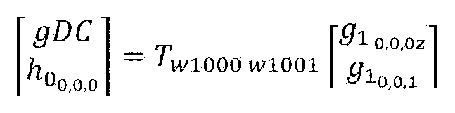
gDC값 또한 하이패스 계수와 같이 양자화되어 엔트로피 코딩된다.
도 10은 실시예들에 따른 포인트 클라우드 디코더(Point Cloud Decoder)의 예시를 나타낸다.
도 10에 도시된 포인트 클라우드 디코더는 도 1에서 설명한 포인트 클라우드 비디오 디코더(10006) 예시로서, 도 1에서 설명한 포인트 클라우드 비디오 디코더(10006)의 동작 등과 동일 또는 유사한 동작을 수행할 수 있다. 도면이 도시된 바와 같이 포인트 클라우드 디코더는 하나 또는 그 이상의 비트스트림(bitstream)들에 포함된 지오메트리 비트스트림(geometry bitstream) 및 어트리뷰트 비트스트림(attribute bitstream)을 수신할 수 있다. 포인트 클라우드 디코더는 지오메트리 디코더(geometry decoder)및 어트리뷰트 디코더(attribute decoder)를 포함한다. 지오메트리 디코더는 지오메트리 비트스트림에 대해 지오메트리 디코딩을 수행하여 디코딩된 지오메트리(decoded geometry)를 출력한다. 어트리뷰트 디코더는 디코딩된 지오메트리 및 어트리뷰트 비트스트림을 기반으로 어트리뷰트 디코딩을 수행하여 디코딩된 어트리뷰트들(decoded attributes)을 출력한다. 디코딩된 지오메트리 및 디코딩된 어트리뷰트들은 포인트 클라우드 콘텐트를 복원(decoded point cloud)하는데 사용된다.
도 11은 실시예들에 따른 포인트 클라우드 디코더(Point Cloud Decoder)의 예시를 나타낸다.
도 11에 도시된 포인트 클라우드 디코더는 도 10에서 설명한 포인트 클라우드 디코더의 예시로서, 도 1 내지 도 9에서 설명한 포인트 클라우드 인코더의 인코딩 동작의 역과정인 디코딩 동작을 수행할 수 있다.
도 1 및 도 10에서 설명한 바와 같이 포인트 클라우드 디코더는 지오메트리 디코딩 및 어트리뷰트 디코딩을 수행할 수 있다. 지오메트리 디코딩은 어트리뷰트 디코딩보다 먼저 수행된다.
실시예들에 따른 포인트 클라우드 디코더는 아리스메틱 디코더(arithmetic decode, 11000), 옥트리 합성부(synthesize octree, 11001), 서페이스 오프록시메이션 합성부(synthesize surface approximation, 11002), 지오메트리 리컨스트럭션부(reconstruct geometry, 11003), 좌표계 역변환부(inverse transform coordinates, 11004), 아리스메틱 디코더(arithmetic decode, 11005), 역양자화부(inverse quantize, 11006), RAHT변환부(11007), LOD생성부(generate LOD, 11008), 인버스 리프팅부(Inverse lifting, 11009), 및/또는 컬러 역변환부(inverse transform colors, 11010)를 포함한다.
아리스메틱 디코더(11000), 옥트리 합성부(11001), 서페이스 오프록시메이션 합성부(11002), 지오메트리 리컨스럭션부(11003), 좌표계 역변환부(11004)는 지오메트리 디코딩을 수행할 수 있다. 실시예들에 따른 지오메트리 디코딩은 다이렉트 코딩(direct coding) 및 트라이숩 지오메트리 디코딩(trisoup geometry decoding)을 포함할 수 있다. 다이렉트 코딩 및 트라이숩 지오메트리 디코딩은 선택적으로 적용된다. 또한 지오메트리 디코딩은 위의 예시에 국한되지 않으며, 도 1 내지 도 9에서 설명한 지오메트리 인코딩의 역과정으로 수행된다.
실시예들에 따른 아리스메틱 디코더(11000)는 수신한 지오메트리 비트스트림을 아리스메틱 코딩을 기반으로 디코딩한다. 아리스메틱 디코더(11000)의 동작은 아리스메틱 인코더(40004)의 역과정에 대응한다.
실시예들에 따른 옥트리 합성부(11001)는 디코딩된 지오메트리 비트스트림으로부터 (또는 디코딩 결과 확보된 지오메트리에 관한 정보)로부터 오큐판시 코드를 획득하여 옥트리를 생성할 수 있다. 오큐판시 코드에 대한 구체적인 설명은 도 1 내지 도 9에서 설명한 바와 같다.
실시예들에 따른 서페이스 오프록시메이션 합성부(11002)는 트라이숩 지오메트리 인코딩이 적용된 경우, 디코딩된 지오메트리 및/또는 생성된 옥트리에 기반하여 서페이스를 합성할 수 있다.
실시예들에 따른 지오메트리 리컨스트럭션부(11003)는 서페이스 및 또는 디코딩된 지오메트리에 기반하여 지오메트리를 재생성할 수 있다. 도 1 내지 도 9에서 설명한 바와 같이, 다이렉트 코딩 및 트라이숩 지오메트리 인코딩은 선택적으로 적용된다. 따라서 지오메트리 리컨스트럭션부(11003)는 다이렉트 코딩이 적용된 포인트들의 포지션 정보들을 직접 가져와서 추가한다. 또한, 트라이숩 지오메트리 인코딩이 적용된 경우, 지오메트리 리컨스트럭션부(11003)는 지오메트리 리컨스트럭션부(40005)의 재구성 동작, 예를 들면 삼각형 재구성, 업-샘플링, 복셀화 동작을 수행하여 지오메트리를 복원할 수 있다. 구체적인 내용은 도 6에서 설명한 바와 동일하므로 생략한다. 복원된 지오메트리는 어트리뷰트들을 포함하지 않는 포인트 클라우드 픽쳐 또는 프레임을 포함할 수 있다.
실시예들에 따른 좌표계 역변환부(11004)는 복원된 지오메트리를 기반으로 좌표계를 변환하여 포인트들의 포지션들을 획득할 수 있다.
아리스메틱 디코더(11005), 역양자화부(11006), RAHT 변환부(11007), LOD생성부(11008), 인버스 리프팅부(11009), 및/또는 컬러 역변환부(11010)는 도 10에서 설명한 어트리뷰트 디코딩을 수행할 수 있다. 실시예들에 따른 어트리뷰트 디코딩은 RAHT(Region Adaptive Hierarchial Transform) 디코딩, 예측 변환(Interpolaration-based hierarchical nearest-neighbour prediction-Prediction Transform) 디코딩 및 리프팅 변환 (interpolation-based hierarchical nearest-neighbour prediction with an update/lifting step (Lifting Transform)) 디코딩을 포함할 수 있다. 상술한 3가지의 디코딩들은 선택적으로 사용되거나, 하나 또는 그 이상의 디코딩들의 조합이 사용될 수 있다. 또한 실시예들에 따른 어트리뷰트 디코딩은 상술한 예시에 국한되는 것은 아니다.
실시예들에 따른 아리스메틱 디코더(11005)는 어트리뷰트 비트스트림을 아리스메틱 코딩으로 디코딩한다.
실시예들에 따른 역양자화부(11006)는 디코딩된 어트리뷰트 비트스트림 또는 디코딩 결과 확보한 어트리뷰트에 대한 정보를 역양자화(inverse quantization)하고 역양자화된 어트리뷰트들(또는 어트리뷰트 값들)을 출력한다. 역양자화는 포인트 클라우드 인코더의 어트리뷰트 인코딩에 기반하여 선택적으로 적용될 수 있다.
실시예들에 따라 RAHT 변환부(11007), LOD생성부(11008) 및/또는 인버스 리프팅부(11009)는 재구성된 지오메트리 및 역양자화된 어트리뷰트들을 처리할 수 있다. 상술한 바와 같이 RAHT 변환부(11007), LOD생성부(11008) 및/또는 인버스 리프팅부(11009)는 포인트 클라우드 인코더의 인코딩에 따라 그에 대응하는 디코딩 동작을 선택적으로 수행할 수 있다.
실시예들에 따른 컬러 역변환부(11010)는 디코딩된 어트리뷰트들에 포함된 컬러 값(또는 텍스쳐)을 역변환하기 위한 역변환 코딩을 수행한다. 컬러 역변환부(11010)의 동작은 포인트 클라우드 인코더의 컬러 변환부(40006)의 동작에 기반하여 선택적으로 수행될 수 있다.
도 11의 포인트 클라우드 디코더의 엘레멘트들은 도면에 도시되지 않았으나 포인트 클라우드 제공 장치에 포함된 하나 또는 그 이상의 메모리들과 통신가능하도록 설정된 하나 또는 그 이상의 프로세서들 또는 집적 회로들(integrated circuits)을 포함하는 하드웨어, 소프트웨어, 펌웨어 또는 이들의 조합으로 구현될 수 있다. 하나 또는 그 이상의 프로세서들은 상술한 도 11의 포인트 클라우드 디코더의 엘레멘트들의 동작들 및/또는 기능들 중 적어도 어느 하나 이상을 수행할 수 있다. 또한 하나 또는 그 이상의 프로세서들은 도11의 포인트 클라우드 디코더의 엘레멘트들의 동작들 및/또는 기능들을 수행하기 위한 소프트웨어 프로그램들 및/또는 인스트럭션들의 세트를 동작하거나 실행할 수 있다.
도 12는 실시예들에 따른 전송 장치의 예시이다.
도 12에 도시된 전송 장치는 도 1의 전송장치(10000) (또는 도 4의 포인트 클라우드 인코더)의 예시이다. 도 12에 도시된 전송 장치는 도 1 내지 도 9에서 설명한 포인트 클라우드 인코더의 동작들 및 인코딩 방법들과 동일 또는 유사한 동작들 및 방법들 중 적어도 어느 하나 이상을 수행할 수 있다. 실시예들에 따른 전송 장치는 데이터 입력부(12000), 양자화 처리부(12001), 복셀화 처리부(12002), 옥트리 오큐판시 코드 (Occupancy code) 생성부(12003), 표면 모델 처리부(12004), 인트라/인터 코딩 처리부(12005), 아리스메틱 (Arithmetic) 코더(12006), 메타데이터 처리부(12007), 색상 변환 처리부(12008), 어트리뷰트 변환 처리부(또는 속성 변환 처리부)(12009), 예측/리프팅/RAHT 변환 처리부(12010), 아리스메틱 (Arithmetic) 코더(12011) 및/또는 전송 처리부(12012)를 포함할 수 있다.
실시예들에 따른 데이터 입력부(12000)는 포인트 클라우드 데이터를 수신 또는 획득한다. 데이터 입력부(12000)는 포인트 클라우드 비디오 획득부(10001)의 동작 및/또는 획득 방법(또는 도2에서 설명한 획득과정(20000))과 동일 또는 유사한 동작 및/또는 획득 방법을 수행할 수 있다.
데이터 입력부(12000), 양자화 처리부(12001), 복셀화 처리부(12002), 옥트리 오큐판시 코드 (Occupancy code) 생성부(12003), 표면 모델 처리부(12004), 인트라/인터 코딩 처리부(12005), Arithmetic 코더(12006)는 지오메트리 인코딩을 수행한다. 실시예들에 따른 지오메트리 인코딩은 도 1 내지 도 9에서 설명한 지오메트리 인코딩과 동일 또는 유사하므로 구체적인 설명은 생략한다.
실시예들에 따른 양자화 처리부(12001)는 지오메트리(예를 들면 포인트들의 위치값, 또는 포지션값)을 양자화한다. 양자화 처리부(12001)의 동작 및/또는 양자화는 도 4에서 설명한 양자화부(40001)의 동작 및/또는 양자화와 동일 또는 유사하다. 구체적인 설명은 도 1 내지 도 9에서 설명한 바와 동일하다.
실시예들에 따른 복셀화 처리부(12002)는 양자화된 포인트들의 포지션 값을 복셀화한다. 복셀화 처리부(120002)는 도 4에서 설명한 양자화부(40001)의 동작 및/또는 복셀화 과정과 동일 또는 유사한 동작 및/또는 과정을 수행할 수 있다. 구체적인 설명은 도 1 내지 도 9에서 설명한 바와 동일하다.
실시예들에 따른 옥트리 오큐판시 코드 생성부(12003)는 복셀화된 포인트들의 포지션들을 옥트리 구조를 기반으로 옥트리 코딩을 수행한다. 옥트리 오큐판시 코드 생성부(12003)는 오큐판시 코드를 생성할 수 있다. 옥트리 오큐판시 코드 생성부(12003)는 도 4 및 도 6에서 설명한 포인트 클라우드 인코더 (또는 옥트리 분석부(40002))의 동작 및/또는 방법과 동일 또는 유사한 동작 및/또는 방법을 수행할 수 있다. 구체적인 설명은 도 1 내지 도 9에서 설명한 바와 동일하다.
실시예들에 따른 표면 모델 처리부(12004)는 표면 모델(surface model)을 기반으로 특정 영역(또는 노드)내의 포인트들의 포지션들을 복셀 기반으로 재구성하는 트라이숩 지오메트리 인코딩을 수행할 수 있다. 포면 모델 처리부(12004)는 도 4 에서 설명한 포인트 클라우드 인코더(예를 들면 서페이스 어프록시메이션 분석부(40003))의 동작 및/또는 방법과 동일 또는 유사한 동작 및/또는 방법을 수행할 수 있다. 구체적인 설명은 도 1 내지 도 9에서 설명한 바와 동일하다.
실시예들에 따른 인트라/인터 코딩 처리부(12005)는 포인트 클라우드 데이터를 인트라/인터 코딩할 수 있다. 인트라/인터 코딩 처리부(12005)는 도 7에서 설명한 인트라/인터 코딩과 동일 또는 유사한 코딩을 수행할 수 있다. 구체적인 설명은 도 7에서 설명한 바와 동일하다. 실시예들에 따라 인트라/인터 코딩 처리부(12005)는 아리스메틱 코더(12006)에 포함될 수 있다.
실시예들에 따른 아리스메틱 코더(12006)는 포인트 클라우드 데이터의 옥트리 및/또는 근사화된 옥트리를 엔트로피 인코딩한다. 예를 들어, 인코딩 방식은 아리스메틱(Arithmetic) 인코딩 방법을 포함한다. . 아리스메틱 코더(12006)는 아리스메틱 인코더(40004)의 동작 및/또는 방법과 동일 또는 유사한 동작 및/또는 방법을 수행한다.
실시예들에 따른 메타데이터 처리부(12007)는 포인트 클라우드 데이터에 관한 메타데이터, 예를 들어 설정 값 등을 처리하여 지오메트리 인코딩 및/또는 어트리뷰트 인코딩 등 필요한 처리 과정에 제공한다. 또한 실시예들에 따른 메타데이터 처리부(12007)는 지오메트리 인코딩 및/또는 어트리뷰트 인코딩과 관련된 시그널링 정보를 생성 및/또는 처리할 수 있다. 실시예들에 따른 시그널링 정보는 지오메트리 인코딩 및/또는 어트리뷰트 인코딩과 별도로 인코딩처리될 수 있다. 또한 실시예들에 따른 시그널링 정보는 인터리빙 될 수도 있다.
색상 변환 처리부(12008), 어트리뷰트 변환 처리부(12009), 예측/리프팅/RAHT 변환 처리부(12010), 아리스메틱 (Arithmetic) 코더(12011)는 어트리뷰트 인코딩을 수행한다. 실시예들에 따른 어트리뷰트 인코딩은 도 1 내지 도 9에서 설명한 어트리뷰트 인코딩과 동일 또는 유사하므로 구체적인 설명은 생략한다.
실시예들에 따른 색상 변환 처리부(12008)는 어트리뷰트들에 포함된 색상값을 변환하는 색상 변환 코딩을 수행한다. 색상 변환 처리부(12008)는 재구성된 지오메트리를 기반으로 색상 변환 코딩을 수행할 수 있다. 재구성된 지오메트리에 대한 설명은 도 1 내지 도 9에서 설명한 바와 동일하다. 또한 도 4에서 설명한 컬러 변환부(40006)의 동작 및/또는 방법과 동일 또는 유사한 동작 및/또는 방법을 수행한다. 구체적인 설명은 생략한다.
실시예들에 따른 어트리뷰트 변환 처리부(12009)는 지오메트리 인코딩이 수행되지 않은 포지션들 및/또는 재구성된 지오메트리를 기반으로 어트리뷰트들을 변환하는 어트리뷰트 변환을 수행한다. 어트리뷰트 변환 처리부(12009)는 도 4에 설명한 어트리뷰트 변환부(40007)의 동작 및/또는 방법과 동일 또는 유사한 동작 및/또는 방법을 수행한다. 구체적인 설명은 생략한다. 실시예들에 따른 예측/리프팅/RAHT 변환 처리부(12010)는 변환된 어트리뷰트들을 RAHT 코딩, 예측 변환 코딩 및 리프팅 변환 코딩 중 어느 하나 또는 조합하여 코딩할 수 있다. 예측/리프팅/RAHT 변환 처리부(12010)는 도 4에서 설명한 RAHT 변환부(40008), LOD 생성부(40009) 및 리프팅 변환부(40010)의 동작들과 동일 또는 유사한 동작들 중 적어도 하나 이상을 수행한다. 또한 예측 변환 코딩, 리프팅 변환 코딩 및 RAHT 변환 코딩에 대한 설명은 도 1 내지 도 9에서 설명한 바와 동일하므로 구체적인 설명은 생략한다.
실시예들에 따른 아리스메틱 코더(12011)는 코딩된 어트리뷰트들을 아리스메틱 코딩에 기반하여 인코딩할 수 있다. 아리스메틱 코더(12011)는 아리스메틱 인코더(400012)의 동작 및/또는 방법과 동일 또는 유사한 동작 및/또는 방법을 수행한다.
실시예들에 따른 전송 처리부(12012)는 인코딩된 지오메트리 및/또는 인코딩된 어트리뷰트, 메타 데이터 정보를 포함하는 각 비트스트림을 전송하거나, 인코딩된 지오메트리 및/또는 인코딩된 어트리뷰트, 메타 데이터 정보를 하나의 비트스트림으로 구성하여 전송할 수 있다. 실시예들에 따른 인코딩된 지오메트리 및/또는 인코딩된 어트리뷰트, 메타 데이터 정보가 하나의 비트스트림으로 구성되는 경우, 비트스트림은 하나 또는 그 이상의 서브 비트스트림들을 포함할 수 있다. 실시예들에 따른 비트스트림은 시퀀스 레벨의 시그널링을 위한 SPS (Sequence Parameter Set), 지오메트리 정보 코딩의 시그널링을 위한 GPS(Geometry Parameter Set), 어트리뷰트 정보 코딩의 시그널링을 위한 APS(Attribute Parameter Set), 타일 레벨의 시그널링을 위한 TPS (Tile Parameter Set)를 포함하는 시그널링 정보 및 슬라이스 데이터를 포함할 수 있다. 슬라이스 데이터는 하나 또는 그 이상의 슬라이스들에 대한 정보를 포함할 수 있다. 실시예들에 따른 하나의 슬라이스는 하나의 지오메트리 비트스트림(Geom0
0) 및 하나 또는 그 이상의 어트리뷰트 비트스트림들(Attr0
0, Attr1
0)을 포함할 수 있다. 실시예들에 따른 TPS는 하나 또는 그 이상의 타일들에 대하여 각 타일에 관한 정보(예를 들면 bounding box의 좌표값 정보 및 높이/크기 정보 등)을 포함할 수 있다. 지오메트리 비트스트림은 헤더와 페이로드를 포함할 수 있다. 실시예들에 따른 지오메트리 비트스트림의 헤더는 GPS에 포함된 파라미터 세트의 식별 정보(geom_ parameter_set_id), 타일 식별자(geom_tile_id), 슬라이스 식별자(geom_slice_id) 및 페이로드에 포함된 데이터에 관한 정보 등을 포함할 수 있다. 상술한 바와 같이 실시예들에 따른 메타데이터 처리부(12007)는 시그널링 정보를 생성 및/또는 처리하여 전송 처리부(12012)로 전송할 수 있다. 실시예들에 따라, 지오메트리 인코딩을 수행하는 엘레멘트들 및 어트리뷰트 인코딩을 수행하는 엘레멘트들은 점선 처리된 바와 같이 상호 데이터/정보를 공유할 수 있다. 실시예들에 따른 전송 처리부(12012)는 트랜스미터(10003)의 동작 및/또는 전송 방법과 동일 또는 유사한 동작 및/또는 전송 방법을 수행할 수 있다. 구체적인 설명은 도 1 내지 도 2에서 설명한 바와 동일하므로 생략한다.
도 13은 실시예들에 따른 수신 장치의 예시이다.
도 13에 도시된 수신 장치는 도 1의 수신장치(10004) (또는 도 10 및 도 11의 포인트 클라우드 디코더)의 예시이다. 도 13에 도시된 수신 장치는 도 1 내지 도 11에서 설명한 포인트 클라우드 디코더의 동작들 및 디코딩 방법들과 동일 또는 유사한 동작들 및 방법들 중 적어도 어느 하나 이상을 수행할 수 있다.
실시예들에 따른 수신 장치는 수신부(13000), 수신 처리부(13001), 아리스메틱 (arithmetic) 디코더(13002), 오큐판시 코드 (Occupancy code) 기반 옥트리 재구성 처리부(13003), 표면 모델 처리부(삼각형 재구성, 업-샘플링, 복셀화)(13004), 인버스(inverse) 양자화 처리부(13005), 메타데이터 파서(13006), 아리스메틱 (arithmetic) 디코더(13007), 인버스(inverse)양자화 처리부(13008), 예측/리프팅/RAHT 역변환 처리부(13009), 색상 역변환 처리부(13010) 및/또는 렌더러(13011)를 포함할 수 있다. 실시예들에 따른 디코딩의 각 구성요소는 실시예들에 따른 인코딩의 구성요소의 역과정을 수행할 수 있다.
실시예들에 따른 수신부(13000)는 포인트 클라우드 데이터를 수신한다. 수신부(13000)는 도 1의 리시버(10005)의 동작 및/또는 수신 방법과 동일 또는 유사한 동작 및/또는 수신 방법을 수행할 수 있다. 구체적인 설명은 생략한다.
실시예들에 따른 수신 처리부(13001)는 수신한 데이터로부터 지오메트리 비트스트림 및/또는 어트리뷰트 비트스트림을 획득할 수 있다. 수신 처리부(13001)는 수신부(13000)에 포함될 수 있다.
아리스메틱 디코더(13002), 오큐판시 코드 기반 옥트리 재구성 처리부(13003), 표면 모델 처리부(13004) 및 인버스 양자화 처리부(13005)는 지오메트리 디코딩을 수행할 수 있다. 실시예들에 따른 지오메트리 디코딩은 도 1 내지 도 10에서 설명한 지오메트리 디코딩과 동일 또는 유사하므로 구체적인 설명은 생략한다.
실시예들에 따른 아리스메틱 디코더(13002)는 지오메트리 비트스트림을 아리스메틱 코딩을 기반으로 디코딩할 수 있다. 아리스메틱 디코더(13002)는 아리스메틱 디코더(11000)의 동작 및/또는 코딩과 동일 또는 유사한 동작 및/또는 코딩을 수행한다.
실시예들에 따른 오큐판시 코드 기반 옥트리 재구성 처리부(13003)는 디코딩된 지오메트리 비트스트림으로부터 (또는 디코딩 결과 확보된 지오메트리에 관한 정보)로부터 오큐판시 코드를 획득하여 옥트리를 재구성할 수 있다. 오큐판시 코드 기반 옥트리 재구성 처리부(13003)는 옥트리 합성부(11001)의 동작 및/또는 옥트리 생성 방법과 동일 또는 유사한 동작 및/또는 방법을 수행한다. 실시예들에 따른 표면 모델 처리부(13004)는 트라이숩 지오메트리 인코딩이 적용된 경우, 표면 모델 방식에 기반하여 트라이숩 지오메트리 디코딩 및 이와 관련된 지오메트리 리컨스트럭션(예를 들면 삼각형 재구성, 업-샘플링, 복셀화)을 수행할 수 있다. 표면 모델 처리부(13004)는 서페이스 오프록시메이션 합성부(11002) 및/또는 지오메트리 리컨스트럭션부(11003)의 동작과 동일 또는 유사한 동작을 수행한다.
실시예들에 따른 인버스 양자화 처리부(13005)는 디코딩된 지오메트리를 인버스 양자화할 수 있다.
실시예들에 따른 메타데이터 파서(13006)는 수신한 포인트 클라우드 데이터에 포함된 메타데이터, 예를 들어 설정 값 등을 파싱할 수 있다. 메타데이터 파서(13006)는 메타데이터를 지오메트리 디코딩 및/또는 어트리뷰트 디코딩에 전달할 수 있다. 메타데이터에 대한 구체적인 설명은 도 12에서 설명한 바와 동일하므로 생략한다.
아리스메틱 디코더(13007), 인버스 양자화 처리부(13008), 예측/리프팅/RAHT 역변환 처리부(13009) 및 색상 역변환 처리부(13010)는 어트리뷰트 디코딩을 수행한다. 어트리뷰트 디코딩는 도 1 내지 도 10에서 설명한 어트리뷰트 디코딩과 동일 또는 유사하므로 구체적인 설명은 생략한다.
실시예들에 따른 아리스메틱 디코더(13007)는 어트리뷰트 비트스트림을 아리스메틱 코딩으로 디코딩할 수 있다. 아리스메틱 디코더(13007)는 재구성된 지오메트리를 기반으로 어트리뷰트 비트스트림의 디코딩을 수행할 수 있다. 아리스메틱 디코더(13007)는 아리스메틱 디코더(11005)의 동작 및/또는 코딩과 동일 또는 유사한 동작 및/또는 코딩을 수행한다.
실시예들에 따른 인버스 양자화 처리부(13008)는 디코딩된 어트리뷰트 비트스트림을 인버스 양자화할 수 있다. 인버스 양자화 처리부(13008)는 역양자화부(11006)의 동작 및/또는 역양자화 방법과 동일 또는 유사한 동작 및/또는 방법을 수행한다.
실시예들에 따른 예측/리프팅/RAHT 역변환 처리부(13009)는 재구성된 지오메트리 및 역양자화된 어트리뷰트들을 처리할 수 있다. 예측/리프팅/RAHT 역변환 처리부(13009)는 RAHT 변환부(11007), LOD생성부(11008) 및/또는 인버스 리프팅부(11009)의 동작들 및/또는 디코딩들과 동일 또는 유사한 동작들 및/또는 디코딩들 중 적어도 어느 하나 이상을 수행한다. 실시예들에 따른 색상 역변환 처리부(13010)는 디코딩된 어트리뷰트들에 포함된 컬러 값(또는 텍스쳐)을 역변환하기 위한 역변환 코딩을 수행한다. 색상 역변환 처리부(13010)는 컬러 역변환부(11010)의 동작 및/또는 역변환 코딩과 동일 또는 유사한 동작 및/또는 역변환 코딩을 수행한다. 실시예들에 따른 렌더러(13011)는 포인트 클라우드 데이터를 렌더링할 수 있다.
도 14는 실시예들에 따른 G-PCC 기반 포인트 클라우드 콘텐트 스트리밍을 위한 아키텍쳐를 나타낸다.
도 14의 상단은 도 1 내지 도 13에서 설명한 전송 장치(예를 들면 전송 장치(10000), 도 12의 전송 장치 등)가 포인트 클라우드 콘텐트를 처리 및 전송하는 과정을 나타낸다.
도 1 내지 도 13에서 설명한 바와 같이 전송 장치는 포인트 클라우드 콘텐트의 오디오(Ba)를 획득하고(Audio Acquisition), 획득한 오디오를 인코딩(Audio encoding)하여 오디오 비트스트림(Ea)들을 출력할 수 있다. 또한 전송 장치는 포인트 클라우드 콘텐트의 포인트 클라우드(Bv)(또는 포인트 클라우드 비디오)를 확보하고(Point Acqusition), 확보한 포인트 클라우드에 대하여 포인트 클라우드 인코딩(Point cloud encoding)을 수행하여 포인트 클라우드 비디오 비트스트림(Eb)들을 출력할 수 있다. 전송 장치의 포인트 클라우드 인코딩은 도 1 내지 도 13에서 설명한 포인트 클라우드 인코딩(예를 들면 도 4의 포인트 클라우드 인코더의 인코딩 등)과 동일 또는 유사하므로 구체적인 설명은 생략한다.
전송 장치는 생성된 오디오 비트스트림들 및 비디오 비트스트림들을 파일 및/또는 세그먼트로 인캡슐레이션(File/segment encapsulation)할 수 있다. 인캡슐레이션된 파일 및/또는 세그먼트(Fs, File)은 ISOBMFF 등의 파일 포맷의 파일 또는 DASH 세그먼트를 포함할 수 있다. 실시예들에 따른 포인트 클라우드 관련 메타 데이터(metadata)는 인캡슐레이션된 파일 포맷 및/또는 세그먼트에 포함될 수 있다. 메타 데이터는 ISOBMFF 파일 포맷 상의 다양한 레벨의 박스(box)에 포함되거나 파일 내에서 별도의 트랙에 포함될 수 있다. 실시예에 따라 전송 장치는 메타데이터 자체를 별도의 파일로 인캡슐레이션할 수 있다. 실시예들에 따른 전송 장치는 인캡슐레이션 된 파일 포맷 및/또는 세그먼트를 네트워크를 통해 전송(delivery)할 수 있다. 전송 장치의 인캡슐레이션 및 전송 처리 방법은 도 1 내지 도 13에서 설명한 바 (예를 들면 트랜스미터(10003), 도 2의 전송 단계(20002) 등)와 동일하므로 구체적인 설명은 생략한다.
도 14의 하단은 도 1 내지 도 13에서 설명한 수신 장치(예를 들면 수신 장치(10004), 도 13의 수신 장치 등)가 포인트 클라우드 콘텐트를 처리 및 출력하는 과정을 나타낸다.
실시예들에 따라 수신 장치는 최종 오디오 데이터 및 최종 비디오 데이터를 출력하는 디바이스 (예를 들면 스피커(Loudspeakers), 헤드폰들(headphones), 디스플레이(Display))와 포인트 클라우드 콘텐트를 처리하는 포인트 클라우드 플레이어(Point Cloud Player)를 포함할 수 있다. 최종 데이터 출력 디바이스 및 포인트 클라우드 플레이어는 별도의 물리적인 디바이스들로 구성될 수 있다. 실시예들에 따른 포인트 클라우드 플레이어는 G-PCC(Geometry-based Point Cloud Compression) 코딩 및/또는 V-PCC(Video based Point Cloud Compression) 코딩 및/또는 차세대 코딩을 수행할 수 있다.
실시예들에 따른 수신 장치는 수신한 데이터(예를 들면 방송 신호, 네트워크를 통해 전송되는 신호 등)에 포함된 파일 및/또는 세그먼트(F',Fs')를 확보하고 디캡슐레이션(File/segment decapsulation)할 수 있다. 수신 장치의 수신 및 디캡슐레이션 방법은 도 1 내지 도 13에서 설명한 바(예를 들면 리시버(10005), 수신부(13000), 수신 처리부(13001)등)와 동일하므로 구체적인 설명은 생략한다.
실시예들에 따른 수신 장치는 파일 및/또는 세그먼트에 포함된 오디오 비트스트림(E'a) 및 비디오 비트스트림(E'v)를 확보한다. 도면에 도시된 바와 같이 수신 장치는 오디오 비트스트림에 대해 오디오 디코딩(audio decoding)을 수행하여 디코딩된 오디오 데이터(B'a)를 출력하고, 디코딩된 오디오 데이터를 렌더링(audio rendering)하여 최종 오디오 데이터(A'a)를 스피커 또는 헤드폰 등을 통해 출력한다.
또한 수신 장치는 비디오 비트스트림(E'v)에 대해 포인트 클라우드 디코딩(point cloud decoding)을 수행하여 디코딩된 비디오 데이터(B'v)를 출력한다. 실시예들에 따른 포인트 클라우드 디코딩은 도 1 내지 도 13에서 설명한 포인트 클라우드 디코딩과 동일 또는 유사하므로 (예를 들면 도11의 포인트 클라우드 디코더의 디코딩 등) 구체적인 설명은 생략한다. 수신 장치는 디코딩된 비디오 데이터를 렌더링(rendering)하여 최종 비디오 데이터를 디스플레이를 통해 출력할 수 있다.
실시예들에 따른 수신 장치는 함께 전송된 메타데이터를 기반으로 디캡슐레이션, 오디오 디코딩, 오디오 렌더링, 포인트 클라우드 디코딩 및 렌더링 동작 중 적어도 어느 하나 이상을 수행할 수 있다. 메타데이터에 대한 설명은 도 12 내지 도 13에서 설명한 바와 동일하므로 생략한다.
도면에 도시된 점선과 같이, 실시예들에 따른 수신 장치(예를 들면 포인트 클라우드 플레이어 또는 포인트 클라우드 플레어 내의 센싱/트랙킹부(sensing/tracking))는 피드백 정보(orientation, viewport)를 생성할 수 있다. 실시예들에 따른 피드백 정보는 수신 장치의 디캡슐레이션, 포인트 클라우드 디코딩 과정 및/또는 렌더링 과정에서 사용될 수도 있고, 송신 장치로 전달 될 수도 있다. 피드백 정보에 대한 설명은 도 1 내지 도 13에서 설명한 바와 동일하므로 생략한다.
도15는 실시예들에 따른 전송 장치의 예시를 나타낸다.
도 15의 전송 장치는 포인트 클라우드 콘텐트를 전송하는 장치로서, 도 1 내지 도 14에서 설명한 전송 장치(예를 들면 도 1의 전송 장치(10000), 도 4의 포인트 클라우드 인코더, 도 12의 전송 장치, 도 14의 전송 장치 등)의 예시에 해당한다. 따라서 도 15의 전송 장치는 도 1 내지 도 14에서 설명한 전송 장치의 동작과 동일 또는 유사한 동작을 수행한다.
실시예들에 따른 전송 장치는 포인트 클라우드 획득(point cloud acquisition), 포인트 클라우드 인코딩(point cloud encoding), 파일/세그먼트 인캡슐레이션(file/segement encapsulation) 및 전송(delivery) 중 적어도 하나 또는 그 이상을 수행할 수 있다.
도면에 도시된 포인트 클라우드 획득 및 전송 동작은 도 1 내지 도 14에서 설명한 바와 동일하므로 구체적인 설명은 생략한다.
도 1 내지 도 14에서 설명한 바와 같이 실시예들에 따른 전송 장치는 지오메트리 인코딩 및 어트리뷰트 인코딩을 수행할 수 있다. 실시예들에 따른 지오메트리 인코딩은 지오메트리 컴프레션(geometry compression)이라 호칭될 수 있으며 어트리뷰트 인코딩은 어트리뷰트 컴프레션(attribute compression)이라 호칭될 수 있다. 상술한 바와 같이 하나의 포인트는 하나의 지오메트리와 하나 또는 그 이상의 어트리뷰트들을 가질 수 있다. 따라서 전송 장치는 각 어트리뷰트에 대하여 어트리뷰트 인코딩을 수행한다. 도면은 전송 장치가 하나 또는 그 이상의 어트리뷰트 컴프레션들(attribute #1 compression, …attribute #N compression)을 수행한 예시를 나타낸다. 또한 실시예들에 따른 전송 장치는 추가 컴프레션(auxiliary compression)을 수행할 수 있다. 추가 컴프레션은 메타데이터(metadata)에 대해 수행된다. 메타 데이터에 대한 설명은 도 1 내지 도 14에서 설명한 바와 동일하므로 생략한다. 또한 전송 장치는 메쉬 데이터 컴프레션(Mesh data compression)을 수행할 수 있다. 실시예들에 따른 메쉬 데이터 컴프레션은 도 1 내지 도 14에서 설명한 트라이숩 지오메트리 인코딩을 포함할 수 있다.
실시예들에 따른 전송 장치는 포인트 클라우드 인코딩에 따라 출력된 비트스트림들(예를 들면 포인트 클라우드 스트림들)을 파일 및/또는 세그먼트로 인캡슐레이션 할 수 있다. 실시예들에 따라 전송 장치는 메타 데이터 외의 데이터(예를 들면 미디어 데이터)를 운반하는 미디어 트랙 인캡슐레이션(media track encapsulation)을 수행하고, 메타 데이터를 운반하는 메타데이터 트랙 인캡슐레이션(metadata tracak encapsulation)을 수행할 수 있다. 실시예들에 따라 메타데이터는 미디어 트랙으로 인캡슐레이션 될 수 있다.
도 1 내지 도 14에서 설명한 바와 같이 전송 장치는 수신 장치로부터 피드백 정보(오리엔테이션/뷰포트 메타 데이터)를 수신하고, 수신한 피드백 정보를 기반으로 포인트 클라우드 인코딩, 파일/세그먼트 인캡슐레이션 및 전송 동작 중 적어도 어느 하나 이상을 수행할 수 있다. 구체적인 설명은 도 1 내지 도 14에서 설명한 바와 동일하므로 생략한다.
도16은 실시예들에 따른 수신 장치의 예시를 나타낸다.
도 16의 수신 장치는 포인트 클라우드 콘텐트를 수신하는 장치로서, 도 1 내지 도 14에서 설명한 수신 장치(예를 들면 도 1의 수신 장치(10004), 도 11의 포인트 클라우드 디코더, 도 13의 수신 장치, 도 14의 수신 장치 등)의 예시에 해당한다. 따라서 도 16의 수신 장치는 도 1 내지 도 14에서 설명한 수신 장치의 동작과 동일 또는 유사한 동작을 수행한다. 또한 도 16의 수신 장치는 도 15의 전송 장치에서 전송한 신호 등을 받고, 도 15의 전송 장치의 동작의 역과정을 수행할 수 있다.
실시예들에 따른 수신 장치는 수신 (delivery), 파일/세그먼트 디캡슐레이션(file/segement decapsulation), 포인트 클라우드 디코딩(point cloud decoding) 및 포인트 클라우드 렌더링(point cloud rendering) 중 적어도 하나 또는 그 이상을 수행할 수 있다.
도면에 도시된 포인트 클라우드 수신 및 포인트 클라우드 렌더링 동작은 도 1 내지 도 14에서 설명한 바와 동일하므로 구체적인 설명은 생략한다.
도 1 내지 도 14에서 설명한 바와 같이 실시예들에 따른 수신 장치는 네트워크 또는 저장 장치로터 획득한 파일 및/또는 세그먼트에 대해 디캡슐레이션을 수행한다. 실시예들에 따라 수신 장치는 메타 데이터 외의 데이터(예를 들면 미디어 데이터)를 운반하는 미디어 트랙 디캡슐레이션(media track decapsulation)을 수행하고, 메타 데이터를 운반하는 메타데이터 트랙 디캡슐레이션(metadata tracak decapsulation)을 수행할 수 있다. 실시예들에 따라 메타데이터가 미디어 트랙으로 인캡슐레이션 된 경우, 메타 데이터 트랙 디캡슐레이션은 생략된다.
도 1 내지 도 14에서 설명한 바와 같이 수신 장치는 디캡슐레이션을 통해 확보한 비트스트림(예를 들면 포인트 클라우드 스트림들)에 대하여 지오메트리 디코딩 및 어트리뷰트 디코딩을 수행할 수 있다. 실시예들에 따른 지오메트리 디코딩은 지오메트리 디컴프레션(geometry decompression)이라 호칭될 수 있으며 어트리뷰트 디코딩은 어트리뷰트 디컴프레션(attribute decompression)이라 호칭될 수 있다. 상술한 바와 같이 하나의 포인트는 하나의 지오메트리와 하나 또는 그 이상의 어트리뷰트들을 가질 수 있으며 각각 인코딩된다. 따라서 수신 장치는 각 어트리뷰트에 대하여 어트리뷰트 디코딩을 수행한다. 도면은 수신 장치가 하나 또는 그 이상의 어트리뷰트 디컴프레션들(attribute #1 decompression, …attribute #N decompression)을 수행한 예시를 나타낸다. 또한 실시예들에 따른 수신 장치는 추가 디컴프레션(auxiliary decompression)을 수행할 수 있다. 추가 디컴프레션은 메타데이터(metadata)에 대해 수행된다. 메타 데이터에 대한 설명은 도 1 내지 도 14에서 설명한 바와 동일하므로 생략한다. 또한 수신 장치는 메쉬 데이터 디컴프레션(Mesh data decompression)을 수행할 수 있다. 실시예들에 따른 메쉬 데이터 디컴프레션은 도 1 내지 도 14에서 설명한 트라이숩 지오메트리 디코딩을 포함할 수 있다. 실시예들에 따른 수신 장치는 포인트 클라우드 디코딩에 따라 출력된 포인트 클라우드 데이터를 렌더링 할 수 있다.
도 1 내지 도 14에서 설명한 바와 같이 수신 장치는 별도의 센싱/트랙킹 엘레멘트등을 이용하여 오리엔테이션/뷰포트 메타 데이터를 확보하고, 이를 포함하는 피드백 정보를 전송 장치(예를 들면 도 15의 전송 장치)로 전송할 수 있다. 또한 수신 장치는 피드백 정보를 기반으로 수신 동작, 파일/세그먼트 디캡슐레이션 및 포인트 클라우드 디코딩 중 적어도 어느 하나 이상을 수행할 수 있다. 구체적인 설명은 도 1 내지 도 14에서 설명한 바와 동일하므로 생략한다.
도 17은 실시예들에 따른 포인트 클라우드 데이터 송수신 방법/장치와 연동 가능한 구조의 예시를 나타낸다.
도 17의 구조는 서버(1760), 로봇(1710), 자율 주행 차량(1720), XR 장치(1730), 스마트폰(1740), 가전(1750) 및/또는 HMD(1770) 중에서 적어도 하나 이상이 클라우드 네트워크(1710)와 연결된 구성을 나타낸다. 로봇(1710), 자율 주행 차량(1720), XR 장치(1730), 스마트폰(1740) 또는 가전(1750) 등은 장치라 호칭된다. 또한, XR 장치(1730)는 실시예들에 따른 포인트 클라우드 데이터 (PCC) 장치에 대응되거나 PCC장치와 연동될 수 있다.
클라우드 네트워크(1700)는 클라우드 컴퓨팅 인프라의 일부를 구성하거나 클라우드 컴퓨팅 인프라 안에 존재하는 네트워크를 의미할 수 있다. 여기서, 클라우드 네트워크(1700)는 3G 네트워크, 4G 또는 LTE(Long Term Evolution) 네트워크 또는 5G 네트워크 등을 이용하여 구성될 수 있다.
서버(1760)는 로봇(1710), 자율 주행 차량(1720), XR 장치(1730), 스마트폰(1740), 가전(1750) 및/또는 HMD(1770) 중에서 적어도 하나 이상과 클라우드 네트워크(1700)을 통하여 연결되고, 연결된 장치들(1710 내지 1770)의 프로세싱을 적어도 일부를 도울 수 있다.
HMD (Head-Mount Display)(1770)는 실시예들에 따른 XR 디바이스 및/또는 PCC 디바이스가 구현될 수 있는 타입 중 하나를 나타낸다. 실시예들에 따른HMD 타입의 디바이스는, 커뮤니케이션 유닛, 컨트롤 유닛, 메모리 유닛, I/O 유닛, 센서 유닛, 그리고 파워 공급 유닛 등을 포함한다.
이하에서는, 상술한 기술이 적용되는 장치(1710 내지 1750)의 다양한 실시 예들을 설명한다. 여기서, 도 17에 도시된 장치(1710 내지 1750)는 상술한 실시예들에 따른 포인트 클라우드 데이터 송수신 장치와 연동/결합될 수 있다.
<PCC+XR>
XR/PCC 장치(1730)는 PCC 및/또는 XR(AR+VR) 기술이 적용되어, HMD(Head-Mount Display), 차량에 구비된 HUD(Head-Up Display), 텔레비전, 휴대폰, 스마트 폰, 컴퓨터, 웨어러블 디바이스, 가전 기기, 디지털 사이니지, 차량, 고정형 로봇이나 이동형 로봇 등으로 구현될 수도 있다.
XR/PCC 장치(1730)는 다양한 센서들을 통해 또는 외부 장치로부터 획득한 3차원 포인트 클라우드 데이터 또는 이미지 데이터를 분석하여 3차원 포인트들에 대한 위치 데이터 및 어트리뷰트 데이터를 생성함으로써 주변 공간 또는 현실 객체에 대한 정보를 획득하고, 출력할 XR 객체를 렌더링하여 출력할 수 있다. 예컨대, XR/PCC 장치(1730)는 인식된 물체에 대한 추가 정보를 포함하는 XR 객체를 해당 인식된 물체에 대응시켜 출력할 수 있다.
<PCC+자율주행+XR>
자율 주행 차량(1720)은 PCC 기술 및 XR 기술이 적용되어, 이동형 로봇, 차량, 무인 비행체 등으로 구현될 수 있다.
XR/PCC 기술이 적용된 자율 주행 차량(1720)은 XR 영상을 제공하는 수단을 구비한 자율 주행 차량이나, XR 영상 내에서의 제어/상호작용의 대상이 되는 자율 주행 차량 등을 의미할 수 있다. 특히, XR 영상 내에서의 제어/상호작용의 대상이 되는 자율 주행 차량(1720)은 XR 장치(1730)와 구분되며 서로 연동될 수 있다.
XR/PCC영상을 제공하는 수단을 구비한 자율 주행 차량(1720)은 카메라를 포함하는 센서들로부터 센서 정보를 획득하고, 획득한 센서 정보에 기초하여 생성된 XR/PCC 영상을 출력할 수 있다. 예컨대, 자율 주행 차량(1720)은 HUD를 구비하여 XR/PCC 영상을 출력함으로써, 탑승자에게 현실 객체 또는 화면 속의 객체에 대응되는 XR/PCC 객체를 제공할 수 있다.
이때, XR/PCC 객체가 HUD에 출력되는 경우에는 XR/PCC 객체의 적어도 일부가 탑승자의 시선이 향하는 실제 객체에 오버랩되도록 출력될 수 있다. 반면, XR/PCC 객체가 자율 주행 차량의 내부에 구비되는 디스플레이에 출력되는 경우에는 XR/PCC 객체의 적어도 일부가 화면 속의 객체에 오버랩되도록 출력될 수 있다. 예컨대, 자율 주행 차량(1220)은 차로, 타 차량, 신호등, 교통 표지판, 이륜차, 보행자, 건물 등과 같은 객체와 대응되는 XR/PCC 객체들을 출력할 수 있다.
실시예들에 의한 VR (Virtual Reality) 기술, AR (Augmented Reality) 기술, MR (Mixed Reality) 기술 및/또는 PCC(Point Cloud Compression)기술은, 다양한 디바이스에 적용 가능하다.
즉, VR 기술은, 현실 세계의 객체나 배경 등을 CG 영상으로만 제공하는 디스플레이 기술이다. 반면, AR 기술은, 실제 사물 영상 위에 가상으로 만들어진 CG 영상을 함께 보여 주는 기술을 의미한다. 나아가, MR 기술은, 현실세계에 가상 객체들을 섞고 결합시켜서 보여준다는 점에서 전술한 AR 기술과 유사하다. 그러나, AR 기술에서는 현실 객체와 CG 영상으로 만들어진 가상 객체의 구별이 뚜렷하고, 현실 객체를 보완하는 형태로 가상 객체를 사용하는 반면, MR 기술에서는 가상 객체가 현실 객체와 동등한 성격으로 간주된다는 점에서 AR 기술과는 구별이 된다. 보다 구체적으로 예를 들면, 전술한 MR 기술이 적용된 것이 홀로그램 서비스 이다.
다만, 최근에는 VR, AR, MR 기술을 명확히 구별하기 보다는 XR (extended Reality) 기술로 부르기도 한다. 따라서, 본 발명의 실시예들은 VR, AR, MR, XR 기술 모두에 적용 가능하다. 이러한 기술은 PCC, V-PCC, G-PCC 기술 기반 인코딩/디코딩이 적용될 수 있다.
실시예들에 따른 PCC방법/장치는 자율 주행 서비스를 제공하는 차량에 적용될 수 있다.
자율 주행 서비스를 제공하는 차량은 PCC 디바이스와 유/무선 통신이 가능하도록 연결된다.
실시예들에 따른 포인트 클라우드 데이터 (PCC) 송수신 장치는 차량과 유/무선 통신이 가능하도록 연결된 경우, 자율 주행 서비스와 함께 제공할 수 있는 AR/VR/PCC 서비스 관련 콘텐트 데이터를 수신/처리하여 차량에 전송할 수 있다. 또한 포인트 클라우드 데이터 송수신 장치 차량에 탑재된 경우, 포인트 클라우드 송수신 장치는 사용자 인터페이스 장치를 통해 입력된 사용자 입력 신호에 따라 AR/VR/PCC 서비스 관련 콘텐트 데이터를 수신/처리하여 사용자에게 제공할 수 있다. 실시예들에 따른 차량 또는 사용자 인터페이스 장치는 사용자 입력 신호를 수신할 수 있다. 실시예들에 따른 사용자 입력 신호는 자율 주행 서비스를 지시하는 신호를 포함할 수 있다.
도 18은 포인트 클라우드 인코더의 예시를 나타내는 블록도이다.
실시예들에 따른 포인트 클라우드 인코더(1800)(예를 들면 도 1의 포인트 클라우드 비디오 인코더(10002), 도4의 포인트 클라우드 인코더, 도 12, 도 14 및 도 15에서 설명한 포인트 클라우드 인코더 등)는 도 1 내지 도 17에서 설명한 인코딩 동작을 수행할 수 있다. 실시예들에 따른 포인트 클라우드 인코더(1800)는 공간 분할부(1810), 지오메트리 정보 부호화부(1820) 및 속성 정보 부호화부(또는 어트리뷰트 정보 부호화부)(1830)을 포함할 수 있다. 실시예들에 따른 포인트 클라우드 인코더(1800)는 도 18에 도시되지 않았으나 도 1 내지 도 17에서 설명한 인코딩 동작을 수행하기 위한 하나 또는 그 이상의 엘레멘트들을 더 포함할 수 있다.
포인트 클라우드 컴프레션 (Point Cloud Compression, PCC) 데이터 (또는 PCC 데이터, 포인트 클라우드 데이터)는 포인트 클라우드 인코더(1800)의 입력 데이터로서, 지오메트리 및/또는 어트리뷰트를 포함할 수 있다. 실시예들에 따른 지오메트리는 포인트의 포지션(예를 들면 위치)을 나타내는 정보로서, 직교 좌표계, 원통 좌표계, 구면 좌표계 등의 좌표계의 파라미터들로 표현될 수 있다. 실시예들에 따르면, 지오메트리는 지오메트리 정보로 호칭될 수 있고, 어트리뷰트는 어트리뷰트 정보로 호칭될 수 있다.
실시예들에 따른 공간 분할부(1810)는 포인트 클라우드 데이터의 지오메트리 및 어트리뷰트를 생성할 수 있다. 실시예들에 따른 공간 분할부(1810)는 포인트 클라우드 데이터의 포인트 정보를 저장하기 위하여 포인트 클라우드 데이터를 3차원 공간상의 하나 또는 그 이상의 3차원 블록(block)들로 분할할 수 있다. 실시예들에 따른 블록은 타일 그룹(Tile Group), 타일(Tile), 슬라이스(Slice), 부호화 단위(Coding Unit, CU), 예측 단위(Prediction Unit, PU) 또는 변환 단위(Transformation Unit, TU) 중 적어도 어느 하나를 나타낼 수 있다. 실시예들에 따른 공간 분할부(1810)는 옥트리(Octree), 쿼드 트리(Quadtree), 바이너리 트리(Biniary tree), 트리플 트리(Triple tree), k-d 트리 중 적어도 하나에 기반한 분할 동작을 수행할 수 있다. 하나의 블록은 하나 또는 그 이상의 포인트를 포함할 수 있다. 실시예들에 따른 블록은 기설정된 가로 길이 값, 세로 길이 값, 및 높이 값을 갖는 육면체 형태의 블록이 될 수 있다. 실시예에 따른 블록의 크기는 변경 가능하며 상술한 예시에 국한되지 않는다. 실시예들에 따른 공간 분할부(1810)는 블록에 포함된 하나 또는 그 이상의 포인트들에 대한 지오메트리 정보를 생성할 수 있다.
실시예들에 따른 지오메트리 정보 부호화부(1820)(또는 지오메트리 정보 인코더)는 지오메트리 인코딩을 수행하고, 지오메트리 비트스트림 및 복원된 지오메트리 정보를 생성할 수 있다. 실시예들에 따른 지오메트리 인코딩은 복원된 지오메트리 정보는 어트리뷰트 정보 부호화부(또는 어트리뷰트 인코더)(1830)으로 입력된다. 실시예들에 따른 지오메트리 정보 부호화부(1820)는 도 4에서 설명한 좌표계 변환부(40000), 양자화(40001), 옥트리 분석부(40002), 서페이스 어프록시메이션 분석부(40003), 아리스메틱 인코더(40004) 및 지오메트리 리컨스럭션부(Reconstruct Geometry, 40005)의 동작들 중 적어도 하나 이상을 수행할 수 있다. 또한 실시예들에 따른 지오메트리 정보 부호화부(1820)는 도 12에서 설명한 데이터 입력부(12000), 양자화 처리부(12001), 복셀화 처리부(12002), 옥트리 오큐판시 코드 생성부(12003), 표면 모델 처리부(12004), 인트라/인터 코딩 처리부(12005), 아리스메틱 코더(12006), 메타데이터 처리부(12007)의 동작들 중 적어도 하나 이상을 수행할 수 있다.
실시예들에 따른 어트리뷰트 정보 부호화부(1830)는 복원된 지오메트리 정보 및 어트리뷰트를 기반으로 어트리뷰트 정보 비트스트림 (또는 어트리뷰트 비트스트림)을 생성할 수 있다.
실시예들에 따른 포인트 클라우드 인코더는 지오메트리 정보 비트스트림 및 어트리뷰트 정보 비트스트림 또는 지오메트리 정보 비트스트림 및 어트리뷰트 정보 비트스트림이 멀티플렉싱된 비트스트림을 전송될 수 있다. 상술힌 바와 같이 비트스트림은 지오메트리 정보 및 어트리뷰트 정보와 연관된 시그널링 정보, 좌표계 변환과 관련된 시그널링 정보 등을 더 포함할 수 있다. 또한 실시예들에 따른 포인트 클라우드 인코더는 비트스트림을 인캡슐레이션 하여 세그먼트 및/또는 파일 등의 형태로 전송할 수 있다.
도 19는 지오메트리 정보 인코더의 예시를 나타내는 블록도이다.
실시예들에 따른 지오메트리 정보 인코더(1900) (또는 지오메트리 인코더)는 도 18의 지오메트리 정보 부호화부(1820)의 예시로서, 지오메트리 인코딩을 수행할 수 있다. 실시예들에 따른 지오메트리 인코딩은 도 1 내지 도 18에서 설명한 지오메트리 인코딩과 동일 또는 유사하므로 구체적인 설명은 생략한다. 도면에 도시된 바와 같이 지오메트리 정보 인코더(1900)는 좌표계 변환부(1910), 지오메트리 정보 변환양자화부(1920), 지오메트리 정보 예측부(1930), 잔차지오메트리 정보 양자화부(1940), 지오메트리 정보 엔트로피 부호화부(1950), 잔차 지오메트리 정보 역양자화부(1960), 필터링부(1970) 및 메모리(1980)를 포함할 수 있다. 실시예들에 따른 지오메트리 정보 인코더(1900)는 도 19에 도시되지 않았으나 도 1 내지 도 18에서 설명한 지오메트리 인코딩을 수행하기 위한 하나 또는 그 이상의 엘레멘트들을 더 포함할 수 있다.
실시예들에 따른 좌표계 변환부(1910)는 입력된 지오메트리 정보가 나타내는 각 포인트의 포지션을 3차원 공간상의 포지션으로 표현하기 위하여 수신한 지오메트리 정보를 좌표계 상의 정보로 변환할 수 있다. 좌표계 변환부(1910)는 도 4에서 설명한 좌표계 변환부(40000)의 동작과 동일 또는 유사한 동작을 수행한다. 실시예들에 따른 좌표계는 상술한 3차원 직교 좌표계, 원통 좌표계, 구면 좌표계 등을 포함할 수 있으며 예시에 국한되지 않는다. 실시예들에 따른 좌표계 변환부(1910)는 설정된 좌표계를 다른 좌표계로 변환할 수 있다.
실시예들에 따른 좌표계 변환부(1910)는 시퀀스, 프레임, 타일, 슬라이스, 블록 등의 단위에 대해 좌표계 변환을 수행할 수 있다. 실시예들에 따른 좌표계 변환 여부 및 좌표계 및/또는 변환과 관련된 정보는 시퀀스, 프레임, 타일, 슬라이스, 블록 등의 단위로 시그널링 될 수 있다. 따라서 실시예들에 따른 포인트 클라우드 데이터 수신 장치는 주변 블록의 좌표계 변환 여부 블록의 크기, 포인트들의 개수, 양자화 값, 블록 분할 깊이, 단위의 위치, 단위와 원점과의 거리 등을 기반으로 좌표계 및/또는 변환과 관련된 정보를 확보할 수 있다.
실시예들에 따른 지오메트리 정보 변환 양자화부(1920)는 좌표계에서 표현된 지오메트리 정보를 양자화하고 변환 양자화된 지오메트리 정보를 생성할 수 있다. 실시예들에 따른 지오메트리 정보 변환 양자화부(1920)는 좌표계 변환부(1910)에서 출력된 지오메트리 정보가 나타내는 포인트들의 포지션들에 대하여 위치 변환 및/또는 회전 변환 등 하나 또는 그 이상의 변환을 적용하고, 변환된 지오메트리 정보를 양자화 값으로 나누어 양자화를 수행할 수 있다. 지오메트리 정보 변환 양자화부(1920)는 도 4의 양자화부(40001) 및/또는 도 12의 양자화 처리부(12001)의 동작과 동일 또는 유사한 동작을 수행할 수 있다. 실시예들에 따른 양자화 값은 부호화 단위(예를 들면 타일, 슬라이스 등)과 좌표계의 원점과의 거리 또는 기준 방향으로부터의 각도 등을 기초로 가변할 수 있다. 실시예들에 따른 양자화 값은 기설정된 값이 될 수 있다.
실시예들에 따른 지오메트리 정보 예측부(1930)는 주변 부호화 단위의 양자화 값을 기초로 예측값 (또는 예측 지오메트리 정보)을 산출할 수 있다.
잔차 지오메트리 정보 양자화부(1940)는 변환 양자화된 지오메트리 정보 및 예측값을 차분한 잔차 지오메트리 정보를 수신하고, 잔차 지오메트리 정보를 양자화값으로 양자화하여 양자화된 잔차 지오메트리 정보를 생성할 수 있다.
지오메트리 정보 엔트로피 부호화부(1950)는 양자화된 잔차 지오메트리 정보를 엔트로피 인코딩할 수 있다. 실시예들에 따른 엔트로피 인코딩은 지수 골롬(Exponential Golomb), CAVLC(Context-Adaptive Variable Length Coding) 및 CABAC(Context-Adaptive Binary Arithmetic Coding)등을 포함할 수 있다.
잔차 지오메트리 정보 역양자화부(1960)는 양자화된 지오메트리 정보를 양자화 값으로 스케일링 하여 잔차 지오메트리 정보를 복원할 수 있다. 복원된 잔차 지오메트리 정보와 예측 지오메트리 정보는 합산되어 복원된 지오메트리 정보로 생성될 수 있다.
필터링부(1970)는 복원된 지오메트리 정보를 필터링 할 수 있다. 실시예들에 따른 필터링부(1970)는 디블록킹 필터부, 오프셋 보정부 등을 포함할 수 있다. 서로 다른 두 부호화 단위가 다른 좌표계 변환된 지오메트리 정보에 대해 실시예들에 따른 필터링부(1970)는 두 부호화 단위 경계에 추가적인 필터링을 수행할 수 있다.
메모리(1980)는 복원된 지오메트리 정보(또는 복원 지오메트리 정보)를 저장할 수 있다. 저장된 지오메트리 정보는 지오메트리 정보 예측부(1930)에 제공될 수 있다. 또한 메모리에 저장된 복원 지오메트리 정보는 도 18에서 설명한 어트리뷰트 정보 부호화부(1830)에 제공될 수 있다.
도 20은 실시예들에 따른 어트리뷰트 정보 인코더의 예시를 나타낸다.
도 20에 도시된 어트리뷰트 정보 인코더(2000)는 도 18에서 설명한 어트리뷰트 정보 부호화부(1830)의 예시로서 어트리뷰트 인코딩을 수행할 수 있다. 실시예들에 따른 어트리뷰트 인코딩은 도 1 내지 도 17에서 설명한 어트리뷰트 인코딩과 동일 또는 유사하므로 구체적인 설명은 생략한다. 도면에 도시된 바와 같이 실시예들에 따른 어트리뷰트 정보 인코더(2000)는 어트리뷰트 특성 변환부(2010), 지오메트리 정보 맵핑부(2020), 어트리뷰트 정보 변환부(2030), 어트리뷰트 정보 양자화부(2040) 및 어트리뷰트 정보 엔트로피 부호화부(2050)를 포함할 수 있다.
실시예들에 따른 어트리뷰트 특성 변환부(2010)는 어트리뷰트 정보를 수신하고, 수신한 어트리뷰트 정보의 특성(예를 들면 색상 등)을 변환할 수 있다. 예를 들어 어트리뷰트 정보가 색상정보를 포함하는 경우, 어트리뷰트 특성 변환부(2010)는 어트리뷰트 정보의 색공간을 변환할 수 있다(예를 들면 RGB에서 YCbCr). 또한 어트리뷰트 특성 변환부(2010)는 선택적으로 어트리뷰트 정보의 특성을 변환하지 않을 수 있다. 어트리뷰트 특성 변환부(2010)는 어트리뷰트 변환부(40007), 및/또는 색상 변환 처리부(12008)의 동작과 동일 또는 유사한 동작을 수행할 수 있다.
실시예들에 따른 지오메트리 정보 매핑부(2020)는 어트리뷰트 특성 변환부(2010)에서 출력된 어트리뷰트 정보와 수신한 복원 지오메트리 정보를 매핑하여 재구성된 어트리뷰트 정보를 생성할 수 있다. 지오메트리 정보 매핑부(2020)는 복원 지오메트리 정보를 기반으로 하나 또는 그 이상의 포인트들의 어트리뷰트 정보를 재구성한 어트리뷰트 정보를 생성할 수 있다. 상술한 바와 같이 하나의 복셀에 포함된 하나 또는 그 이상의 포인트들의 지오메트리 정보는 복셀의 중앙값을 중심으로 재구성될 수 있다. 어트리뷰트 정보는 지오메트리 정보에 종속되어있으므로, 지오메트리 정보 매핑부(2020)는 복원 지오메트리 정보를 기반으로 어트리뷰트 정보를 재구성한다. 지오메트리 정보 매핑부(2020)는 속성 변환 처리부(12009)의 동작과 동일 또는 유사한 동작을 수행할 수 있다.
실시예들에 따른 어트리뷰트 정보 변환부(2030)는 재구성된 어트리뷰트 정보를 수신하여 변환할 수 있다. 실시예들에 따른 어트리뷰트 정보 변환부(2030)는 어트리뷰트 정보를 예측하고 수신한 재구성된 어트리뷰트 정보와 예측 어트리뷰트 정보간의 잔차에 대응하는 잔차 어트리뷰트 정보를 하나 또는 그 이상의 변환 타입 (예를 들면 DCT, DST, SADCT, RAHT)을 사용하여 변환할 수 있다.
실시예들에 따른 어트리뷰 정보 양자화부(2040)는 변환된 잔차 어트리뷰트 정보를 수신하고 양자화 값을 기초로 변환양자화된 잔차 어트리뷰트 정보를 생성할 수 있다.
실시예들에 따른 어트리뷰트 정보 엔트로피 부호화부(2050)는 변환양자화된 잔차 어트리뷰트 정보를 입력 받아 엔트로피 부호화를 수행하고 어트리뷰트 정보 비트스트림을 출력할 수 있다. 실시예들에 따른 엔트로피 부호화는 지수 골롬(Exponential Golomb), CAVLC(Context-Adaptive Variable Length Coding) 및 CABAC(Context-Adaptive Binary Arithmetic Coding) 중 어느 하나 이상을 포함할 수 있으며, 상술한 실시예에 국한되지 않는다. 어트리뷰트 정보 엔트로피 부호화부(2050)는 아리스메틱 코더(12011)의 동작과 동일 또는 유사한 동작을 수행할 수 있다.
도 21은 실시예들에 따른 어트리뷰트 정보 인코더의 예시를 나타낸다.
도 21에 도시된 어트리뷰트 정보 인코더(2100)는 도 18에서 설명한 어트리뷰트 정보 부호화부(1830) 및 도 20에서 설명한 어트리뷰트 정보 인코더(2000)의 예시에 해당한다. 실시예들에 따른 어트리뷰트 정보 인코더(2100)는 어트리뷰트 특성 변환부(2110), 지오메트리 정보 매핑부(2120), 어트리뷰트 정보 예측부(2130), 잔차 어트리뷰트 정보 변환부(2140), 잔차 어트리뷰트 정보 역변환부(2145), 잔차 어트리뷰트 정보 양자화부(2150), 잔차 어트리뷰트 정보 역양자화부(2155), 필터링부(2160), 메모리(2170), 및 어트리뷰트 정보 엔트로피 부호화부(2180)를 포함할 수 있다. 도 21에 도시된 어트리뷰트 정보 인코더(2100)는 잔차 어트리뷰트 정보 변환부(2140), 잔차 어트리뷰트 정보 역변환부(2145), 잔차 어트리뷰트 정보 양자화부(2150), 잔차 어트리뷰트 정보 역양자화부(2155), 필터링부(2160), 메모리(2170)를 더 포함한다는 점에서 도 20에 도시된 어트리뷰트 정보 인코더(2000)과 차이가 있다.
실시예들에 따른 어트리뷰트 특성 변환부(2110) 및 지오메트리 정보 매핑부(2120)는 도 20에서 설명한 어트리뷰트 특성 변환부(2010) 및 지오메트리 정보 매핑부(2020)의 동작과 동일 또는 유사한 동작을 수행할 수 있다. 실시예들에 따른 어트리뷰트 정보 예측부(2130)는 예측 어트리뷰트 정보를 생성할 수 있다. 잔차 어트리뷰트 정보 변환부(2140)는 지오메트리 정보 매핑부(2120)에서 출력된 재구성 어트리뷰트 정보와 예측 어트리뷰트 정보를 차분하여 생성된 잔차 어트리뷰트 정보를 수신할 수 있다. 잔차 어트리뷰트 정보 변환부(2140)는 수신한 잔차 어트리뷰트 정보를 포함하는 잔차 3차원 블록을 하나 또는 그 이상의 변환 타입들(예를 들면 DCT, DST, SADCT, RAHT 등)으로 변화할 수 있다.
실시예들에 따른 잔차 어트리뷰트 정보 양자화부(2150)는 입력된 변환 잔차 어트리뷰트 정보를 양자화값을 기초로 변환할 수 있다. 변환된 잔차 어트리뷰트 정보는 잔차 어트리뷰트 정보 역양자화부(2155)로 입력될 수 있다. 실시예들에 따른 잔차 어트리뷰트 정보 역양자화부(2155)는 변환양자화된 잔차 어트리뷰트 정보를 양자화 값을 기초로 변환하여 변환 잔차 어트리뷰트 정보를 생성할 수 있다. 잔차 어트리뷰트 정보 역양자화부(2155)에서 생성된 변환 잔차 어트리뷰트 정보는 잔차 어트리뷰트 역변환부(2145)로 입력된다. 실시예들에 따른 잔차 어트리뷰트 역변환부(2145)는 변환 잔차 어트리뷰트 정보를 포함한 잔차 3차원 블록을 하나 또는 그 이상의 변환 타입들(예를 들면 DCT, DST, SADCT, RAHT 등)을 사용하여 역변환할 수 있다. 실시예들에 따른 복원 어트리뷰트 정보는 역변환된 잔차 어트리뷰트 정보 및 어트리뷰트 정보 예측부(2130)에서 출력된 예측 어트리뷰트 정보의 결합으로 생성될 수 있다. 실시예들에 따른 복원 어트리뷰트 정보는 역변환되지 않은 잔차 어트리뷰트 정보 및 예측 어트리뷰트 정보의 결합으로 생성될 수 있다. 복원 어트리뷰트 정보는 필터링부(2160)으로 입력될 수 있다. 실시예들에 따른 어트리뷰트 정보 예측부(2130), 잔차 어트리뷰트 정보 변환부(2140) 및/또는 잔차 어트리뷰트 정보 양자화부(2150)는 예측/리프팅/RAHT 변환 처리부(12010)의 동작과 동일 또는 유사한 동작을 수행할 수 있다.
실시예들에 따른 필터링부(2160)는 복원 어트리뷰트 정보를 필터링할 수 있다. 실시예들에 따른 필터링부(2160)는 디블록킹 필터, 오프셋 보정부, ALF(Adaptive Loop Filter) 등을 포함할 수 있다. 필터링부(2160)는 도 19의 필터링부(1970)의 동작과 동일 또는 유사한 동작을 수행할 수 있다.
실시예들에 따른 메모리(2170)는 필터링부(2160)로부터 출력된 복원 어트리뷰트 정보를 저장할 수 있다. 저장된 복원 어트리뷰트 정보는 어트리뷰트 정보 예측부(2130)의 예측 동작의 입력 데이터로 제공될 수 있다. 어트리뷰트 정보 예측부(2130)는 포인트들의 복원 어트리뷰트 정보를 기초로 예측 어트리뷰트 정보를 생성할 수 있다. 도면상 메모리(2170)는 하나의 블록으로 도시되어 있으나, 하나 또는 그 이상의 물리적인 메모리들로 구성될 수 있다. 실시예들에 따른 어트리뷰트 정보 엔트로피 부호화부(2180)는 도 20에서 설명한 어트리뷰트 정보 엔트로피 부호화부(2050)의 동작과 동일 또는 유사한 동작을 수행할 수 있다.
도 22는 실시예들에 따른 어트리뷰트 정보 예측부의 예시를 나타낸다.
도 22에 도시된 어트리뷰트 정보 예측부(2200)는 도 21에서 설명한 어트리뷰트 정보 예측부(2130)의 예시에 해당한다. 어트리뷰트 정보 예측부(2200)는 어트리뷰트 정보 예측부(2130)의 동작과 동일 또는 유사한 동작을 수행할 수 있다. 실시예들에 따른 어트리뷰트 정보 예측부(2200)는 LOD 구성부(2210)를 포함할 수 있다. LOD 구성부(2210)는 LOD 생성부(40009)와 동일 또는 유사한 동작을 수행할 수 있다. 즉, 도면에 도시된 바와 같이 LOD 구성부(2210)는 어트리뷰트 및 복원된 지오메트리를 수신하고 수신한 어트리뷰트 및 복원된 지오메트리를 기반으로 하나 또는 그 이상의 LOD를 구성할 수 있다. 도 4 및 도 8에서 설명한 바와 같이 LOD는 3차원 공간에 분포한 포인트들을 리파인먼트 레벨들(refinement levels)의 세트로 재정열(reorganize)하여 생성될 수 있다. 실시예들에 따른 LOD는 일정 간격으로 분포하는 하나 또는 그 이상의 포인트들을 포함할 수 있다. 상술한 바와 같이 실시예들에 따른 LOD는 포인트 클라우드 콘텐트의 디테일을 나타내는 정도이다. 따라서 LOD(또는 LOD 값)가 나타내는 레벨이 낮을 수록 포인트 클라우드 콘텐트의 디테일이 떨어지고, LOD가 나타내는 레벨이 높을 수록 포인트 클라우드 콘텐트의 디테일이 높음을 나타낸다. 즉, 높은 레벨을 나타내는 LOD는 더 짧은 간격으로 분포하는 포인트들을 포함할 수 있다. 실시예들에 따른 포인트 클라우드 인코더 (예를 들면 도 4의 포인트 클라우드 인코더) 및 포인트 클라우드 디코더 (예를 들면 도 11의 포인트 클라우드 디코더)는 어트리뷰트 압축율을 높이기 위해LOD를 생성할 수 있다. 유사한 어트리뷰트를 갖는 포인트들은 대상 포인트의 이웃에 있을 확률이 높기 때문에 유사한 속성을 갖는 이웃 포인트를 통한 예측 어트리뷰트와 대상 포인트의 어트리뷰트 간의 잔차 값은 0에 가까울 확률이 높기 때문이다. 따라서 실시예들에 따른 포인트 클라우드 인코더 및 포인트 클라우드 디코더는 어트리뷰트 예측시 사용할 수 있는 적절한 이웃 포인트를 선택하기 위하여 LOD를 생성할 수 있다.
실시예들에 따른LOD 구성부(2210)는 하나 또는 그 이상의 방식들을 이용하여 LOD를 구성할 수 있다. 상술한 바와 같이 포인트 클라우드 디코더(예를 들면 도 10내지 도 11에서 설명한 포인트 클라우드 디코더 등)도 LOD를 생성해야 한다. 따라서 실시예들에 따른 하나 또는 그 이상의 LOD 구성 방식(또는 LOD 생성 방식)들과 관련된 정보는 지오메트리 인코딩 및 어트리뷰트 인코딩에 따라 생성되는 비트스트림에 포함된다. LOD 구성부(2210)에서 출력된 LOD는 예측 변환/역변환부 및 리프팅 변환/역변환부 중 적어도 어느 하나 이상으로 전송된다.
실시예들에 따른LOD 구성부(2210)는 LOD
l 집합을 생성할 때 포인트들 간의 거리를 계산하는 복잡도를 낮추면서 포인트 간의 일정 간격을 유지할 수 있는 하나 또는 그 이상의 방법들을 기반으로 LOD를 생성할 수 있다.
실시예들에 따른 LDO 구성부(2210)는 각 LOD마다 적어도 두개의 포인트들 사이의 거리(예를 들면 유클리디언 디스턴스)를 설정하고, 3차원 공간에 분포한 모든 포인트들 사이의 거리를 계산하여 계산 결과를 기반으로 LOD를 생성할 수 있다(이웃 포인트들 간의 거리 계산 기반 LOD 생성 방법). 상술한 바와 같이 각 LOD는 LOD가 나타내는 레벨에 따라 일정 간격으로 분포하는 포인트들을 포함할 수 있다. 따라서 LOD 구성부(2210)는 모든 포인트들 사이의 거리를 계산해야만 한다. 즉, 포인트 클라우드 인코더 및 포인트 클라우드 디코더는 LOD를 생성할 때마다 모든 포인트들 사이의 거리를 계산해야 하므로 포인트 클라우드 데이터를 처리하는 과정에서 불필요한 버든(burden)을 야기할 수 있다.
실시예들에 따른 LOD 구성부(2210)는 바이너리 트리를 기반으로 LOD를 생성할 수 있다(바이너리 트리 기반 LOD 생성 방법). 바이너리 트리는 포인트들이 분포되어 있는 3차원 공간을 나타내기 위한 구조이다. 실시예들에 따른 바이너리 트리는 하나의 부모 노드가 적어도 두개의 자식 노드들을 가지는 트리 구조로서, 하나의 노드는 적어도 하나의 포인트를 포함할 수 있다. 실시예들에 따른 LOD 구성부(2210)는 바이너리 트리를 기반으로 포인트들 사이의 거리를 계산하여 보다 효율적으로 LOD를 구성할 수 있다. 하지만 바이너리 트리를 기반으로 포인트들 사이의 거리를 계산하기 위해서는 추가적인 메모리가 필요하다.
실시예들에 따른 LOD 구성부(2210)는 포인트들의 몰톤 코드를 기반으로 LOD를 구성할 수 있다. 상술한 바와 같이 몰튼 코드는 모든 포인트들의 3차원 포지션을 나타내는 좌표값(예를 들면 (x, y, z))을 비트값으로 나타내고, 비트들을 믹싱하여 생성된다.
실시예들에 따른 LOD 구성부(2210)는 복원된 지오메트리를 기반으로 각 포인트의 몰톤 코드를 생성하고 몰톤 코드를 기반으로 각 포인트를 오름차순으로 정렬할 수 있다. 몰톤 코드의 오름차순으로 정렬된 포인트들의 순서를 몰톤 순서(Morton order)라 호칭할 수 있다. LOD 구성부(2210)는 몰톤 순서로 정렬된 포인트들에 대해 샘플링을 수행하여 LOD를 구성할 수 있다(몰톤 순서 기반 샘플링 방법).
도 23은 몰톤 순서 기반 샘플링 과정의 예시를 나타낸다.
도 23의 좌측은 3차원 공간이 분할된 하나의 공간 내 포인트들의 몰톤 순서(2300)를 나타낸다. 상술한 바와 같이 실시예들에 따른 LOD 구성부(예를 들면 LOD 구성부(2210))는 각 포인트의 몰톤 코드를 계산하고 계산된 몰톤 코드 기반으로 각 포인트를 오름차순으로 정렬할 수 있다. 도면에 도시된 번호는 몰톤 코드를 기반으로 오름차순으로 정렬된 포인트의 순서를 나타낸다. 도 23의 가운데는 3차원 공간이 분할된 복수의 공간들 내 포인트들의 몰톤 순서들에 대하여 샘플링을 수행하여 생성된 LOD의 예시(2310)를 나타낸다. 도 23의 예시(2310)는 샘플링 레이트가 4인 예시를 나타낸다. 좌표계 내에 표현된 원(2315)은 샘플링 과정에서 선택된 포인트를 나타낸다. 좌표계 내에 표시된 선(2318)은 포인트를 선택하는 과정을 나타낸다. 상술한 바와 같이 LOD 구성부(예를 들면 LOD 구성부(2210))는 몰튼 순서로 정렬된 포인트들에 대해 샘플링을 수행하여 LOD를 구성할 수 있다. 도 23의 우측은 몰튼 순서 기반의 샘플링을 수행하여 생성된 LOD의 예시를 나타낸다(2320). 도23의 우측에 도시된 예시(2320)는 도 23의 예시(2310)가 나타내는 3차원 공간에서 분할된 공간을 나타내는 박스를 제거한 예시이다. 지그재그 형태의 선은 몰톤 순서를 나타낸다. 도 23의 우측의 예시(2320)에 표현된 원(2325)는 샘플링 과정에서 선택된 포인트를 나타낸다. 실시예들에 따른 LOD 구성부는 몰튼 순서에 대해 샘플링을 적용하여 포인트들 간의 거리 계산을 최소화하여 LOD를 생성할 수 있다. 하지만 도 23의 예시(예를 들면 예시 (2310) 및 예시 (2320))에 도시된 바와 같이 몰톤 순서는 지그재그 형태의 선으로 표현될 수 있다. 따라서 몰톤 순서에 따라 정렬된 포인트들 사이의 거리는 일정하지 않을 수 있다. 또한 포인트들이 3차원 영역(예를 들면 X축, Y축 Z축으로 표현되는 3차원 영역)에 골고루 분포하지 않는다. 따라서 몰톤 순서로 정렬된 포인트들에 대하여 일정한 샘플링 레이트로 샘플링을 수행하더라도 샘플링 결과가 포인트들 간의 거리의 최소 및 최대값을 보장하지 않을 수 있다.
도 24는 몰톤 순서 기반 샘플링 과정의 예시를 나타낸다.
도 24는 도 23의 예시로서, 실시예들에 따른 LOD 구성부(예를 들면 LOD 구성부(2210))가 몰톤 순서로 정렬된 포인트들에 대해 샘플링 레이트 4로 샘플링을 수행하여 LOD를 생성하는 과정을 나타낸다. 도면에 도시된 알파벳은 몰톤 코드 기반으로 오름차순으로 정렬된 포인트들을 나타낸다. 따라서 실시예들에 따른 LOD 구성부는 알파벳 순서대로 각 알파벳에 대응하는 포인트를 샘플링 하여 LOD를 생성할 수 있다. 실시예들에 따른 샘플링 레이트는 4이므로, LOD 구성부는 샘플링을 수행하여 알파벳a, d, h, l에 대응하는 포인트들을 선택한다. 선택된 포인트들은 LOD를 구성한다. 실시예들에 따른 알파벳 a에 대응하는 포인트(이하 포인트 a)의 좌표는 (0,0,0)으로 표현되고, 알파벳 d에 대응하는 포인트(이하 포인트 d)의 좌표는 (1,1,3)으로 표현된다. 또한 알파벳 h에 대응하는 포인트(이하 포인트 h)의 좌표는 (1,2,2,)로 표현되고 알파벳l에 대응하는 포인트(이하 포인트 l)의 좌표는 (0,2,3)으로 표현된다. 포인트 a(0, 0, 0,)와 포인트 d(1, 1, 3)의 거리는 3.32이고 포인트 d(1, 1, 3)와 포인트 h(1, 2, 2)의 거리는 1.41, 포인트 h(1, 2, 3)와 포인트 l(0, 2, 3)의 거리는 1이다. 따라서 LOD 구성부는 최소 및 최대 일정한 거리 사이에 떨어져 있는 포인트들을 선택하여 LOD 를 생성할 수 없다. 예를 들어 LOD 구성부가 포인트 a, 포인트 g, 포인트 l 및 포인트 b를 선택하는 경우, 포인트들간의 거리는 2가 된다.
상술한 문제점을 해결하기 위하여 실시예들에 따른 LOD 구성부는 옥트리(octree) 기반 몰톤 순서 샘플링을 수행하여 LOD를 생성할 수 있다. 도5 내지 도 6에서 설명한 바와 같이 실시예들에 따른 옥트리는 포인트 클라우드 콘텐트의 3차원 공간을 재귀적으로 분할하여 생성되고, 생성된 옥트리는 하나의 공간이 분할되어 발생되는 8개의 분할된 공간들 각각이 적어도 하나의 포인트를 포함하는지 여부를 나타내는 오큐판시 코드를 가진다. 오큐판시 코드는 복수의 노드들을 포함하며, 각 노드는 적어도 하나의 LOD가 나타내는 레벨에 대응한다. 각 레벨에 대응하는 노드 영역은 LOD 내의 포인트간의 최대 거리를 보장해줄 수 있다. 실시예들에 따른 옥트리 기반 몰톤 순서 샘플링은 노드 내의 포인트들 중 선택된 포인트들간의 최대 거리는 노드 크기이고, 노드와 노드 사이에서 선택된 포인트들간의 최대 거리는 노드 크기로 제한된다. 따라서 실시예들에 따른 옥트리 기반 몰톤 순서 샘플링은 포인트들 간의 최대 거리를 일정하게 유지할 수 있으므로 LOD 구성부는 LOD 생성의 복잡도를 낮추고 압축 효율이 높은 LOD를 생성할 수 있다.
도 25는 실시예들에 따른 옥트리의 예시를 나타낸다.
실시예들에 따른 포인트 클라우드 인코더(예를 들면 도 4의 포인트 클라우드 인코더) 및 포인트 클라우드 디코더(예를 들면 도 11의 포인트 클라우드 디코더)는 포인트 클라우드 콘텐트의 3차원 공간을 재귀적으로 분할하여 옥트리 구조를 생성할 수 있다.
도 25의 좌측은 도 5 내지 도 6에서 설명한 옥트리의 오큐판시 코드(2500)를 나타낸다. 실시예들에 따른 LOD 구성부(예를 들면 LOD 구성부(2210))는 샘플링을 수행하기 위하여 오큐판시 코드(2500)의 뎁스(depth)를 기반으로 결정된 LOD 레벨에 따라 포인트 클라우드 영역을 분할할 수 있다.
도 25의 우측은 오큐판시 코드(2500)의 뎁스 2에 대응하는 LOD 레벨 0(LOD
0)에 따라 포인트 클라우드 영역을 분할하는 과정의 예시(2510)이다. 실시예들에 따른 뎁스 2의 오큐판시 코드 노드들의 개수는 8개이므로 LOD 구성부는 뎁스 2에 대응하는 포인트 클라우드 내 영역(2520)을 8등분으로 재귀적 분할을 할 수 있다. 재귀적으로 분할된 영역들은 동일한 부피를 가진 정육면체 또는 직육면체의 형태를 가진다. 따라서 포인트 클라우드 영역은 8개의 뎁스2에 대응하는 영역(2520)들로 분할된다 도면에 도시된 바와 같이 뎁스 2의 옥트리의 오큐판시 코드는 여러 개의 노드들을 포함하며 재귀적으로 분할된 영역들은 뎁스 2의 자식 노드들의 뎁스에 대응한다. 즉, 뎁스 2에 대응하는 영역(2520)은 각각 8등분으로 다시 분할되며 분할된 각 영역(2530)은 뎁스 3에 대응한다. 따라서 하나의 뎁스 2에 대응하는 영역(2520)은 8개의 뎁스 3에 대응하는 영역(2530)들을 포함한다. 뎁스 3에 대응하는 영역(2530)은 LOD 레벨 1(LOD
1)에 대응한다. 뎁스 3에 대응하는 영역(2530)은 다시 8등분으로 분할되며, 분할된 각 영역(2540)은 뎁스 4에 대응한다. 따라서 뎁스 3에 대응하는 영역(2530)은 8개의 뎁스 4에 대응하는 영역(2540)들을 포함한다.
도 26은 실시예들에 따른 뎁스 2에 대응하는 영역의 예시를 나타낸다.
도 25에 도시된 바와 같이 포인트 클라우드 콘텐트의 3차원 공간 또는 포인트 클라우드 영역을 분할하면, 3차원 공간 또는 영역 내에 분포한 모든 포인트들은 각각 오큐판시 코드의 노드 영역(예를 들면 노드의 뎁스에 대응하는 영역)에 할당된다. 즉, 각 노드 영역에 속하는 각 노드는 해당 노드에 대응하는 포인트들에 대한 인덱스 정보를 가진다. 또한 각 노드 영역에 대응하는 포인트들은 몰톤 순서 기반으로 정렬된다.
도 26은 도 25에서 설명한 뎁스 2에 대응하는 영역(2510)의 예시(2600)이다. 도 26에 도시된 바와 같이 뎁스 2에 대응하는 영역들 각각은 하나 또는 그 이상의 포인트들을 포함할 수 있다. 예를 들어 도 26에 도시된 바와 같이 뎁스 2의 제 1 노드에 대응하는 제 1 영역(2610)은 4개의 포인트를 포함할 수 있다. 또한 예를 들어 뎁스 2의 제 2 노드에 대응하는 제 2 영역(2620)은 9개의 포인트들을 포함할 수 있다. 실시예들에 따른 각 노드는 Node
level=뎁스 레벨, xyz=해당 뎁스 레벨에서의 해당 포인트의 좌표값으로 표현되는 포인트들의 인덱스 정보를 가질 수 있다. 실시예들에 따른 해당 뎁스 레벨에서의 좌표값(또는 위치값)은 1의 단위가 1개의 노드의 너비(width)를 X의 유닛으로 높이(height)를 Y의 유닛으로 깊이(depth)를 Z의 유닛으로 하여 결정된다. 예를 들어 도 26에 도시된 제 1 포인트(2611)는 좌표값이 (0,0,0)으로 표현되므로 제 1 영역(2610)에 대응하는 제 2 노드는 Node
level=2, xyz=000의 인덱스를 갖는다. 즉, 해당 노드는 뎁스 레벨이 2이고, 뎁스 레벨 2에서 좌표값 X=0, Y=0, Z=0가 나타내는 위치에 존재하는 포인트를 포함함을 나타낸다. 또한 도 26에 도시된 제 2 포인트(2611)는 좌표값이 (1,0,0)으로 표현되므로 제 2 영역 (2620)에 대응하는 노드는 Node
level=2, xyz=100의 인덱스를 갖는다. 즉, 해당 노드는 뎁스 레벨이 2이고, 뎁스 레벨 2에서 좌표값 X=1, Y=0, Z=0가 나타내는 위치에 존재하는 포인트를 포함한다.
도 27은 실시예들에 따른 샘플링 과정의 예시를 나타낸다.
실시예들에 따른 LOD 구성부(예를 들면 LOD 구성부(2210))는 뎁스 2 에 대응하는 영역들(예를 들면 도 26에서 설명한 제 1 영역(2610), 제 2 영역(2620) 등)에 포함된 뎁스 2에 대응하는 포인트들에 대하여 샘플링을 수행할 수 있다. 실시예들에 따른 샘플링 개수는 노드에 포함된 포인트들의 개수에서 샘플링 레이트를 나눈 값 또는 반올림(round)한 값이 될 수 있다. 실시예들에 따른 샘플링 레이트는 각 LOD마다 다르게 설정할 수 있다.
실시예들에 따른 LOD 구성부는 다양한 방식으로 샘플링을 수행할 수 있다. 예를 들어, 실시예들에 따른 LOD 구성부는 노드에 대응하는 각 영역에 포함된 포인트들의 몰톤 순서에 따라 순차적으로 샘플링 레이트의 갭을 기반으로 포인트를 선택할 수 있다. 즉, LOD 구성부는 몰톤 순서에 따라 가장 첫번째로 정렬된 포인트(0번째 포인트)를 선택하고 첫번째 포인트로부터 샘플링 레이트 만큼 떨어진 포인트들(예를 들면 샘플링 레이트가 5인 경우 첫번째 포인트로부터 5번째 포인트)을 샘플링 개수만큼 선택할 수 있다. 또한 실시예들에 따른 LOD 구성부는 노드의 중심 포인트의 몰톤 코드 값과 주변 포인트들의 몰톤 코드 값을 기반으로 중심 포인트의 몰톤 코드 값과 가장 근사한 몰톤 코드 값을 갖는 포인트를 샘플링 개수만큼 선택할 수 있다. 또한 실시예들에 따른 LOD 구성부는 노드의 중심 포인트로부터 가장 가까운 포인트들을 정렬하고, 중심 포인트(0번째 포인트)를 선택하고, 중심 포인트로부터 샘플링 레이트의 갭만큼 떨어진 포인트들을 샘플링 개수만큼 선택할 수 있다.
도 27에 도시된 검은색 처리된 점들은 제 1 LOD (예를 들면 LOD0)의 샘플링 레이트가 5 인 경우, 포인트들의 몰톤 순서에 따라 순차적으로 샘플링 레이트의 갭을 기반으로 선택된 포인트들을 나타낸다. 뎁스 2의 제 1 노드에 대응하는 제 1 영역(2710)(예를 들면 제 1 영역(2610))은 5개의 포인트들을 포함한다. 따라서 제 1 영역(2710)의 샘플링 개수는 1(=5/5)개 이므로, LOD 구성부는 Node
level=2, xyz=000에 인덱스에 대응하는 제 1 포인트(2711)를 선택할 수 있다. 또한 뎁스 2의 제 2 노드에 대응하는 제 2 영역(2720)(예를 들면 제 2 영역(2620))은 9개의 포인트들을 포함한다. 따라서 제 2 영역(2720)의 샘플링 개수는 9개를 샘플링 레이트 5로 나눈 값의 반올림 값인 2개이다. 실시예들에 따른 LOD 구성부는 Node
level=2, xyz=100 의 인덱스에 대응하는 제 2 포인트(2721)를 선택하고, 제 2 포인트(2721)로부터 샘플링 레이트인 5만큼 떨어진 5번째 포인트인 제 3 포인트(2722)를 선택할 수 있다.
도 28은 실시예들에 따른 뎁스 3에 대응하는 영역의 예시를 나타낸다.
도 28은 도 25에서 설명한 뎁스3에 대응하는 영역(2520)의 예시(2800)이다. 실시예들에 따른 LOD 구성부(예를 들면 LOD 구성부(2210))는 도 27에서 설명한 샘플링 과정과 동일 또는 유사한 과정으로 포인트들을 선택하여 뎁스 3에 대응하는 LOD 레벨 1(LOD
1)을 생성할 수 있다. LOD 레벨 1을 생성하기 위해 포인트들을 선택하는 과정에서 도 26에서 설명한 LOD 레벨 0에 등록된 포인트들은 제외된다. 실시예들에 따른 LOD 구성부는 오큐판시 코드의 노드가 리프(leaf)노드일 때까지 도 25 내지 도 28에서 설명한 샘플링 과정을 반복하여 LOD를 생성하거나, LOD 개수가 기설정된 경우 기설정된 LOD 개수만큼 LOD를 생성할 수 있다.
도 29는 실시예들에 따른 LOD 생성 과정을 나타낸다.
도 29는 샘플링 레이트가 5 일 때 LOD 레벨 0(LOD
0)의 생성 과정을 나타낸다. 도 29 좌측은 도 25 내지 도 28에서 설명한 옥트리 기반 몰톤 순서 샘플링 과정의 예시(2900)을 나타내고, 도 29의 우측은 도 23 내지 도 24에서 설명한 몰톤 코드 기반 샘플링 과정의 예시(2910)를 나타낸다. 도면에 나타난 검은색 처리된 점은 각 샘플링 과정에서 선택된 포인트들을 나타낸다. 실시예들에 따른 포인트 클라우드 인코더(예를 들면 도 4의 포인트 클라우드 인코더) 및 포인트 클라우드 디코더(예를 들면 도 11의 포인트 클라우드 디코더)는 콘텐트 마다 옥트리 기반 몰톤 순서 샘플링 과정 및 몰톤 코드 기반 샘플링 과정 중 어느 하나를 선택적으로 사용할 수 있다. 하지만 상술한 바와 같이 몰톤 코드 기반 샘플링 과정은 노드들 간의 거리를 특정 영역으로 한정하지 않으므로 포인트 간의 거리가 일정하지 않을 수 있다. 따라서 도면에 도시된 바와 같이 몰톤 코드 기반 샘플링 과정에서 선택된 포인트들 간의 거리는 옥트리 기반 몰톤 순서 샘플링 과정에서 선택된 포인트들 간의 거리보다 상대적으로 일정하지 않다. 옥트리 기반 몰톤 순서 샘플링 과정은 노드 영역의 포인트들간에 선택된 포인트의 최대 거리는 노드 크기에 대응하고, 노드와 노드 사이에 선택된 포인트 간의 최대 거리 또한 노드 크기로 제한되기 때문에 포인트들 간의 최대 일정 간격을 유지시킬 수 있다.
도 30은 포인트 클라우드 컴프레션 (PCC) 비트스트림의 구조도의 예시를 나타낸다.
상술한 바와 같이, 포인트 클라우드 데이터 송신 장치(예를 들면 도 1, 도 11, 도 14 및 도 1에서 설명한 포인트 클라우드 데이터 송신 장치)는 부호화된 포인트 클라우드 데이터를 비트스트림(3000)의 형태로 전송할 수 있다. 실시예들에 따른 비트스트림(3000)은 하나 또는 그 이상의 서브 비트스트림들을 포함할 수 있다.
포인트 클라우드 데이터 송신 장치(예를 들면 도 1, 도 11, 도 14 및 도 1에서 설명한 포인트 클라우드 데이터 송신 장치)는 전송 채널의 에러를 고려하여 포인트 클라우드 데이터의 영상을 하나 또는 그 이상의 패킷들로 나누어 네트워크를 통해 전송할 수 있다. 실시예들에 따른 비트스트림(3000)은 하나 또는 그 이상의 패킷(예를 들면 NAL (Network Abstraction Layer) 유닛)들을 포함할 수 있다. 따라서 열악한 네트워크 환경에서 일부 패킷이 손실되더라도 포인트 클라우드 데이터 수신 장치는 나머지 패킷들을 이용하여 해당 영상을 복원할 수 있다. 포인트 클라우드 데이터를 하나 또는 그 이상의 슬라이스(slice)들 또는 하나 또는 그 이상의 타일(tile)들로 분할하여 처리할 수 있다. 실시예들에 따른 타일 및 슬라이스는 포인트 클라우드 데이터의 픽처를 파티셔닝(partitioning)하여 포인트 클라우드 컴프레션 코딩 처리하기 위한 영역이다. 포인트 클라우드 데이터 송신 장치는 포인트 클라우드 데이터의 나누어진 영역별 중요도에 따라 각 영역에 대응하는 데이터를 처리하여 고품질의 포인트 클라우드 콘텐트를 제공할 수 있다. 즉, 실시예들에 따른 포인트 클라우드 데이터 송신 장치는 사용자에게 중요한 영역에 대응하는 데이터를 더 좋은 압축 효율과 적절한 레이턴시를 갖는 포인트 클라우드 컴프레션 코딩 처리할 수 있다.
실시예들에 따른 포인트 클라우드 콘텐트의 영상(또는 픽처(picture)은 포인트 클라우드 컴프레션 코딩을 위한 기본 프로세싱 유닛 단위로 분할된다. 실시예들에 따른 포인트 클라우드 컴프레션 코딩을 위한 기본 프로세싱 유닛은 CTU(Coding Tree unit), 브릭(brick)등을 포함할 수 있으며 본 예시에 국한되지 않는다.
실시예들에 따른 슬라이스는 하나 또는 그 이상의 정수개의 포인트 클라우드 컴프레션 코딩을 위한 기본 프로세싱 유닛들을 포함하는 영역으로 직사각형의 형태를 가지지 않는다. 실시예들에 따른 슬라이스는 패킷을 통해 전송되는 데이터를 포함한다. 실시예들에 따른 타일은 영상 내에 직사각형 형태로 분할된 영역으로 하나 또는 그 이상의 포인트 클라우드 컴프레션 코딩을 위한 기본 프로세싱 유닛들을 포함한다. 실시예들에 따른 하나의 슬라이스는 하나 또는 그 이상의 타일들에 포함될 수 있다. 또한 실시예들에 따른 하나의 타일은 하나 또는 그 이상의 슬라이스들에 포함될 수 있다.
실시예들에 따른 비트스트림(3000)은 시퀀스 레벨의 시그널링을 위한 SPS (Sequence Parameter Set), 지오메트리 정보 코딩의 시그널링을 위한 GPS(Geometry Parameter Set), 어트리뷰트 정보 코딩의 시그널링을 위한 APS(Attribute Parameter Set), 타일 레벨의 시그널링을 위한 TPS (Tile Parameter Set)를 포함하는 시그널링 정보 및 하나 또는 그 이상의 슬라이스들을 포함할 수 있다.
실시예들에 따른 SPS는 프로파일, 레벨 등 시퀀스 전체에 대한 인코딩 정보로서, 픽처 해상도, 비디오 포멧 등 파일 전체에 대한 포괄적인 정보를 포함할 수 있다.
실시예들에 따른 하나의 슬라이스(예를 들면 도 30의 slice 0)는 슬라이스 헤더 및 슬라이스 데이터를 포함한다. 슬라이스 데이터는 하나의 지오메트리 비트스트림 (Geom0
0) 및 하나 또는 그 이상의 어트리뷰트 비트스트림들(Attr0
0, Attr1
0)을 포함할 수 있다.. 지오메트리 비트스트림은 헤더(예를 들면 지오메트리 슬라이스 헤더) 및 페이로드(예를 들면 지오메트리 슬라이스 데이터)를 포함할 수 있다. 실시예들에 따른 지오메트리 비트스트림의 헤더는 GPS에 포함된 파라미터 세트의 식별 정보(geom_geom_parameter_set_id), 타일 식별자(geom_tile id), 슬라이스 식별자(geom_slice_id) 및 페이로드에 포함된 데이터에 관한 정보 등을 포함할 수 있다. 어트리뷰트 비트스트림은 헤더 (예를 들면 어트리뷰트 슬라이스 헤더 또는 어트리뷰트 브릭 헤더) 및 페이로드 (예를 들면 어트리뷰트 슬라이스 데이터 또는 어트리뷰트 브릭 데이터)를 포함할 수 있다. 도 18 내지 도 29에서 설명한 바와 같이 실시예들에 따른 포인트 클라우드 인코더 및 포인트 클라우드 디코더는 어트리뷰트 예측시 사용할 수 있는 적절한 이웃 포인트를 선택하기 위하여 LOD를 생성할 수 있다. 따라서 도 30에 도시된 비트스트림은 도 18 내지 도 29에서 설명한 하나 또는 그 이상의 LOD 구성 방식(또는 LOD 생성 방식)들과 관련된 정보를 포함할 수 있다.실시예들에 따른 비트스트림에 포함되는 시그널링 정보는 포인트 클라우드 인코더에 포함된 메타데이터 처리부 또는 전송 처리부(예를 들면 도 12의 전송 처리부(12012)) 또는 메타데이터 처리부 또는 전송 처리부 내의 엘레멘트에 의해 생성될 수 있다. 실시예들에 따른 시그널링 정보는 지오메트리 인코딩 및 어트리뷰트 인코딩의 수행 결과를 기반으로 생성될 수 있다.
도 31은 실시예들에 따른 APS를 위한 신택스의 예시이다.
실시예들에 따른 APS는 LOD 생성 방식과 관련된 시그널링 정보를 포함할 수 있다. 도 31은 실시예들에 따른 APS를 위한 신택스의 예시(3100)으로서 다음의 정보(또는 필드, 파라미터 등)를 포함할 수 있다.
aps_attr_parameter_set_id 는 다른 신택스 엘리먼트들에 의한 참조를 위한 APS의 식별자를 나타낸다. aps_attr_parameter_set_id 는 0 내지 15 범위 내의 값을 가진다. 도 30에 도시된 바와 같이 비트스트림 내에는 하나 또는 그 이상의 어트리뷰트 비트스트림들이 포함되므로, 각 어트리뷰트 비트스트림의 헤더에는 aps_attr_parameter_set_id와 동일한 값을 갖는 필드(예를 들면 ash_attr_parameter_set_id)가 포함될 수 있다. 실시예들에 따른 포인트 클라우드 디코더는 aps_attr_parameter_set_id를 기반으로 각 어트리뷰트 비트스트림에 대응하는 APS를 확보하고 해당 어트리뷰트 비트스트림을 처리할 수 있다.
aps_seq_parameter_set_id 는 액티브 SPS(active SPS)를 위한 sps_seq_parameter_set_id 의 값을 나타낸다. aps_seq_parameter_set_id 는 0 내지 15의 범위 내의 값을 가진다.
attr_coding_type 는 attr_coding_type 의 주어진 값에 대한 어트리뷰트 코딩 타입(coding type)을 나타낸다. attr_coding_type의 값은 실시예들에 따른 비트스트림들내에서 0, 1 또는 2 중 어느 하나와 같다. 다른 attr_coding_type의 값들은 ISO/IEC에 의해 추후 사용될 수 있을 수 있다. 따라서 실시예들에 따른 디코더들은 상술한 attr_coding_type의 나머지 값들을 무시할 수 있다. 해당 값이 0이면, 어트리뷰트 코딩 타입은 프레딕팅 웨이트 리프팅(predicting weight lifting) 변환 코딩, 1이면 어트리뷰트 코딩 타입이 RAHT 변환 코딩, 2이면 어트리뷰트 코딩 타입은 픽스트 웨이트 리프팅(fixed weight lifting) 변환 코딩이다.
이하는 어트리뷰트 코딩 타입이 0 또는 2인 경우의 파라미터들이다.
num_pred_nearest_neighbours 는 예측 변환(prediction)에 사용되는 니어리스트 네이버(nearest neighbours)의 최대 개수를 나타낸다. numberOfNearestNeighboursInPrediction의 값은 1부터 xx의 범위에 포함될 수 있다.
max_num_direct_predictors 는 다이렉트 예측(direct prediction)변환을 위해 사용되는 예측기(predictors)의 개수를 나타낸다. max_num_direct_predictors는 0부터 num_pred_nearest_neighbours의 값의 범위 내의 값을 가진다. 디코딩 동작에서 사용되는 변수 MaxNumPredictors의 값은 다음과 같다.
MaxNumPredictors = max_num_direct_predicots + 1
lifting_search_range 는 리프팅(lifting)을 위한 탐색 범위(search range)를 나타낸다.
lifting_quant_step_size 는 어트리뷰트의 첫 번째 컴포넌트를 위한 양자화 스텝 사이즈(quantization step size)를 나타낸다. lifting_quant_step_size의 값은 1부터 xx까지의 범위일 수 있다.
lifting_quant_step_size_chroma 는 어트리뷰트가 색(colour)인 경우, 어트리뷰터의 크로마(chroma) 컴포넌트를 위한 양자화 스텝 사이즈(quantization step size)를 나타낼 수 있다. lifting_quant_step_size_chroma는 1부터 xx의 범위를 가질 수 있다.
lod_binary_tree_enabled_flag 는 LOD 생성 과정에서 이진 트리가 적용되는지 여부를 나타낸다.
num_detail_levels_minus1 는 어트리뷰트 부호화(어트리뷰트 코딩)을 위한 LOD의 수를 나타낸다. num_detail_levels_minus1는 0에서 xx의 범위 내의 값을 가질 수 있다. 이하의 for 문은 각 LOD에 대한 정보이다.
sampling_distance_squared [idx] 는 idx로 표현되는 각 LOD에 대한 샘플링 거리(sampling distance)의 제곱을 나타낼 수 있다. 실시예들에 따른 idx는 0부터 num_detail_levels_minus1 가 나타내는 어트리뷰트 코딩을 위한 LOD의 수까지의 값을 갖는다. sampling_distance_squared는 0에서 xx의 범위 내의 값을 가진다.
이하는 실시예들에 따른 LOD 생성 방식과 관련된 시그널링 정보이다.
lod_type은 LOD 생성 방법을 나타내며 타입 정보로 호칭할 수 있다. lod_type는 1, 2, 3 또는 4 중 어느 하나의 값을 갖는다. lod_type값이 1인 경우(예를 들면 제 1 타입), lod_type은 LOD 생성 방법이 이웃 포인트들 간의 거리 계산 기반 LOD 생성 방법임을 나타낸다. 실시예들에 따른 이웃 포인트들 간의 거리 계산 기반 LOD 생성 방법은 각 LOD마다 적어도 두개의 포인트들 사이의 거리(예를 들면 유클리디언 디스턴스)를 설정하고, 3차원 공간에 분포한 모든 포인트들 사이의 거리를 계산하여 계산 결과를 기반으로 LOD를 생성하는 방법이다. 구체적인 설명은 도 22에서 설명한 바와 동일하므로 생략한다. lod_type값이 2인 경우(예를 들면 제 2 타입), lod_type은 LOD 생성 방법이 바이너리 트리 기반 LOD 생성 방법임을 나타낸다. 바이너리 트리 기반 LOD 생성 방법은 도 22에서 설명한 바와 동일하므로 구체적인 설명은 생략한다. lod_type값이 3인 경우(예를 들면 제 3 타입), lod_type은 LOD 생성 방법이 몰톤 순서 기반 샘플링 방법으로 LOD를 생성하는 방법임을 나타낸다. 실시예들에 따른 몰톤 순서 기반 샘플링 방법은 도 23 내지 도 24에서 설명한 바와 동일하므로 구체적인 설명은 생략한다. lod_type값이 4인 경우(예를 들면 제 4 타입), lod_type은 LOD 생성 방법이 옥트리 기반 몰톤 순서 샘플링 방법으로 LOD를 생성하는 방법임을 나타낸다. 실시예들에 따른 옥트리 기반 몰톤 순서 샘플링 방법은 도 25 내지 도 29에서 설명한 바와 동일하므로 구체적인 설명은 생략한다.
이하는 lod_type값이 4인 경우, 즉, LOD 생성 방법이 옥트리 기반 몰톤 순서 샘플링 방법으로 LOD를 생성하는 방법인 경우의 관련 파라미터들이다.
lod_0_depth는 LOD 레벨 0, 즉, LOD
0 에 대응하는 옥트리 오큐판시 코드의 뎁스(depth) 레벨을 나타낸다. lod_0_depth는 뎁스 레벨 정보로 호칭할 수 있다. lod_0_depth의 값은 0보다 크거나 같다. 도 25 내지 도 29에서 설명한 바와 같이 실시예들에 따른 LOD 구성부(예를 들면 LOD 구성부(2210))는 lod_0_depth가 나타내는 뎁스 레벨을 1씩 증가 시켜서 증가한 뎁스 레벨에 대응하는 LOD(예를 들면 뎁스 레벨 1에 대응하는 LOD
1)를 생성할 수 있다. lod_sampling_type는 샘플링 타입을 나타낸다. lod_sampling_type는 LOD 샘플링 타입 정보로 호칭할 수 있으며 각 뎁스 레벨에 대응하는 LOD를 구성하는 하나 또는 그 이상의 포인트들을 선택하는 방법을 나타낸다. 실시예들에 따른 lod_sampling_type은 1, 2, 또는 3 중 어느 하나의 값을 가질 수 있다.
lod_sampling_type가 1 값을 갖는 경우, LOD에 포함된 포인트는 노드 내의 몰톤 순서에 따라 순차적으로 샘플링 레이트의 갭을 기반으로 선택되었음을 나타낸다. 즉, 도 27에서 설명한 바와 같이 실시예들에 따른 LOD 구성부(예를 들면 LOD 구성부(2210))는 노드에 대응하는 각 영역에 포함된 포인트들의 몰톤 순서에 따라 순차적으로 샘플링 레이트의 갭을 기반으로 포인트를 선택할 수 있다.
lod_sampling_type가 2값을 갖는 경우, LOD에 포함된 포인트는 노드의 중심 포인트의 몰톤 코드 값 및 해당 포인트의 몰톤 코드 값을 기반으로 선택되었음을 나타낸다. 도 27에서 설명한 바와 같이 실시예들에 따른 LOD 구성부(예를 들면 LOD 구성부(2210))는 노드의 중심 포인트의 몰톤 코드 값과 주변 포인트들의 몰톤 코드 값을 기반으로 중심 포인트의 몰톤 코드 값과 가장 근사한 몰톤 코드 값을 갖는 포인트를 샘플링 개수만큼 선택할 수 있다.
lod_sampling_type가 3값을 갖는 경우, LOD에 포함된 포인트는 노드의 중심 포인트로부터 거리 순으로 정렬된 순서에 따라 순차적으로 샘플링 레이트의 갭을 기반으로 선택되었음을 나타낸다. 도 27에서 설명한 바와 같이 실시예들에 따른 LOD 구성부(예를 들면 LOD 구성부(2210))는 노드의 중심 포인트로부터 가장 가까운 포인트들을 정렬하고, 중심 포인트(0번째 포인트)를 선택하고, 중심 포인트로부터 샘플링 레이트의 갭만큼 떨어진 포인트들을 샘플링 개수만큼 선택할 수 있다.
lod_sampling_rate는 각 LOD의 샘플링 레이트를 나타낸다. 상술한 바와 같이 샘플링 레이트는 각 LOD 별로 설정된다.
도 32는 실시예들에 따른 APS를 위한 신택스의 예시이다.
도 32는 도 31에서 설명한 APS를 위한 신택스(3100)에 연속되는 APS를 위한 신택스(3200)로서 다음의 정보(또는 필드, 파라미터 등)를 포함할 수 있다.
이하는 어트리뷰트 코딩 타입이 0 값인 경우의 관련 파라미터이다.
adaptive_prediction_threshold 는 예측(프리딕션)의 스레숄드 값을 나타낸다.
이하는 어트리뷰트 코딩 타입이 1 값인 경우의 관련 파라미터들이다.
raht_depth 는 RAHT변환을 위한 LOD 개수를 나타낸다. depthRAHT은 1부터 xx까지의 범위 내의 값을 가진다.
raht_binarylevel_threshold 는 RAHT 코이피션트(coefficient, 계수)를 컷 아웃하기 위한 LOD 를 나타낸다. binaryLevelThresholdRAHT의 값은 0부터 xx까지의 범위 내이다.
raht_quant_step_size 는 어트리뷰트의 첫 번째 컴포넌트에 대한 양자화 스텝 사이즈(quantization step size)를 나타낸다. rath_quant_step_size는 1부터 xx의 범위내의 값을 가진다.
aps_extension_present_flag는 0또는 1 값을 갖는 flag이다.
1 값을 갖는 aps_extension_present_flag 는 APS RBSP 신텍스 스트럭처 내에 aps_extension_data 신텍스 스트럭처가 존재함을 나타낸다. 0 값을 갖는 aps_extension_present_flag는 이 신텍스 스트럭처가 존재하지 않음을 나타낸 것이다. 만약 신택스 스트럭처가 존재하지 않는다면, aps_extension_present_flag의 값은 0과 같은 것으로 추론된다.
aps_extension_data_flag 는 어떤 값을 가질 수 있다. 본 필드의 존재 및 값은 실시예들에 따른 디코더 성능에 영향을 주지 않을 수 있다.
실시예들에 따른 LOD 구성부(예를 들면 LOD 구성부(2210))는 타일 또는 슬라이스 별로 LOD 생성 방식을 다르게 적용할 수 있다. 상술한 바와 같이 포인트 클라우드 데이터 수신 장치도 LOD를 생성해야 하므로, 실시예들에 따른 비트 스트림은 영역별 LOD 생성 방식과 관련된 시그널링 정보를 더 포함할 수 있다.
도 33은 실시예들에 따른 TPS를 위한 신택스의 예시이다.
실시예들에 따른 LOD 구성부가 타일 별로 LOD 생성 방식을 다르게 적용한 경우, 실시예들에 따른 TPS는 LOD 생성 방식과 관련된 시그널링 정보(예를 들면 도 31에서 설명한 LOD 생성 방식과 관련된 시그널링 정보)를 더 포함할 수 있다. 도 33은 실시예들에 따른 TPS를 위한 신택스의 예시(3300)으로서 다음의 정보(또는 필드, 파라미터 등)를 포함할 수 있다.
num_tiles 은 비트스트림을 위해 시그널링되는 타일들의 개수를 나타낸다. 만약 비트스트림을 위해 시그널링되는 타일들이 존재하지 않는 경우, 본 정보의 값은 0으로 추론된다. 이하는 각 타일들에 대한 시그널링 파라미터들이다.
tile_bounding_box_offset_x[ i ] 는 직교 좌표계 내의 i-번째 타일의 x 오프셋을 나타낸다 본 파라미터가 존재하지 않으면, tile_bounding_box_offset_x[ 0 ]의 값은 SPS 에 포함된 sps_bounding_box_offset_x의 값으로 본다.
tile_bounding_box_offset_y[ i ] 는 직교 좌표계 내의 i-번째 타일의 y 오프셋을 나타낸다 본 파라미터가 존재하지 않으면, tile_bounding_box_offset_y[ 0 ]의 값은 SPS에 포함된 sps_bounding_box_offset_y의 값으로 본다.
tile_bounding_box_offset_z[ i ] 는 직교 좌표계 내의 i-번째 타일의 z 오프셋을 나타낸다. 본 파라미터가 존재하지 않으면, tile_bounding_box_offset_z[ 0 ]의 값은 sps_bounding_box_offset_z의 값으로 본다.
tile_bounding_box_scale_factor[ i ] 는 직교 좌표계 내의 i-번째 타일과 관련된 스케일 펙터(scale factor)를 나타낸다. 본 파라미터가 존재하지 않으면, tile_bounding_box_scale_factor[ 0 ]의 값은 sps_bounding_box_scale_factor의 값으로 본다.
tile_bounding_box_size_width[ i ] 는 직교 좌표계 내의 i-번째 타일의 폭(width)를 나타낸다. 본 파라미터가 존재하지 않는 경우, tile_bounding_box_size_width[ 0 ]의 값은 sps_bounding_box_size_width값으로 본다.
tile_bounding_box_size_height[ i ] 는 직교 좌표계 내의 i-번째 타일의 높이(height)를 나타낸다. 본 파라미터가 존재하지 않는 경우, tile_bounding_box_size_height[ 0 ]의 값은 sps_bounding_box_size_height의 값으로 본다.
tile_bounding_box_size_depth[ i ] 는 직교 좌표계 내의 i-번째 타일의 뎁스(depth)를 나타낸다. 본 파라미터가 존재하지 않는 경우, tile_bounding_box_size_depth[ 0 ]의 값은 sps_bounding_box_size_depth의 값으로 본다.
도면에 도시된 바와 같이 실시예들에 따른 TPS는 도 31에서 설명한 LOD 생성 방식과 관련된 시그널링 정보(3310)를 포함할 수 있다. 실시예들에 따른 LOD 생성 방식과 관련된 시그널링 정보(3310)는 각 타일마다 적용된다. LOD 생성 방식과 관련된 시그널링 정보는 도 31에서 설명한 시그널링 정보와 동일하므로 구체적인 설명은 생략한다.
도 34는 실시예들에 따른 어트리뷰트 헤더를 위한 신택스의 예시이다.
도 34의 어트리뷰트 헤더를 위한 신택스(3400)은 도 30에서 설명한 어트리뷰트 비트스트림에 포함된 헤더를 통해 전송되는 정보들의 신택스의 예시이다.
실시예들에 따른 LOD 구성부가 슬라이스 별로 LOD 생성 방식을 다르게 적용한 경우, 실시예들에 따른 어트리뷰트 헤더는 LOD 생성 방식과 관련된 시그널링 정보(예를 들면 도 31에서 설명한 LOD 생성 방식과 관련된 시그널링 정보)를 더 포함할 수 있다. 도 34는 실시예들에 따른 어트리뷰트 헤더를 위한 신택스의 예시(3400)으로서 다음의 정보(또는 필드, 파라미터 등)를 포함할 수 있다.
ash_attr_parameter_set_id는 액티브 APS들의 aps_attr_parameter_set_id 와 동일한 값을 갖는다.
ash_attr_sps_attr_idx는 액티브 SPS(active SPS)에 대한 sps_seq_parameter_set_id의 값을 나타낼 수 있다. ash_attr_sps_attr_idx의 값은 0부터 액티브 SPS내에 포함된 sps_num_attribute_sets 값까지의 범위 내에 속한다.
ash_attr_geom_slice_id는 지오메트리 슬라이스 아이디(예를 들면 geom_slice_id)의 값을 나타낸다.
도면에 도시된 바와 같이 실시예들에 따른 어트리뷰트 헤더는 도 31에서 설명한 LOD 생성 방식과 관련된 시그널링 정보(3410)를 포함할 수 있다. 실시예들에 따른 LOD 생성 방식과 관련된 시그널링 정보(3410)는 각 슬라이스에 속한 어트리뷰트 비트스트림(또는 어트리뷰트 슬라이스 데이터)마다 적용된다. LOD 생성 방식과 관련된 시그널링 정보는 도 31에서 설명한 시그널링 정보와 동일하므로 구체적인 설명은 생략한다.
도 35은 포인트 클라우드 디코더의 예시를 나타내는 블록도이다.
실시예들에 따른 포인트 클라우드 디코더(3500)는 도 1 내지 도 17에서 설명한 디코더(예를 들면 도 1, 도 10-도 11, 도 13-도 14 및 도 16에서 설명한 포인트 클라우드 디코더)의 디코딩 동작과 동일 또는 유사한 디코딩 동작을 수행할 수 있다. 또한 포인트 클라우드 디코더(3500)는 도 18에서 설명한 포인트 클라우드 인코더(1800)의 인코딩 동작의 역과정에 해당하는 디코딩 동작을 수행할 수 있다. 실시예들에 따른 포인트 클라우드 디코더(3500)는 공간 분할부(3510), 지오메트리 정보 복호화부(3520) (또는 지오메트리 정보 디코더) 및 어트리뷰트 정보 복호화부(또는 어트리뷰트 디코더)(3530)을 포함할 수 있다. 실시예들에 따른 포인트 클라우드 디코더(3500)는 도 35에 도시되지 않았으나 도 1 내지 도 17에서 설명한 디코딩 동작을 수행하기 위한 하나 또는 그 이상의 엘레멘트들을 더 포함할 수 있다.
실시예들에 따른 공간 분할부(3510)는 실시예들에 따른 포인트 클라우드 데이터 전송 장치(예를 들면 도 1, 도 11, 도 14 및 도 1에서 설명한 포인트 클라우드 데이터 송신 장치)으로부터 수신한 시그널링 정보 (예를 들면 도 18에서 설명한 공간 분할부(1810)에서 수행된 분할 동작에 대한 정보) 또는 포인트 클라우드 디코더(3500)에서 유도한(생성한) 분할 정보를 기반으로 공간을 분할할 수 있다. 상술한 바와 같이 포인트 클라우드 인코더(1800)의 공간 분할부(1810)의 분할 동작은 옥트리(Octree), 쿼드 트리(Quadtree), 바이너리 트리(Biniary tree), 트리플 트리(Triple tree), k-d 트리 중 적어도 하나에 기반할 수 있다.
실시예들에 따른 지오메트리 정보 복호화부(3520)는 입력한 지오메트리 비트스트림을 복호화하여 지오메트리 정보를 복원할 수 있다. 복원된 지오메트리 정보는 속성 정보 복호화부로 입력 될 수 있다. 실시예들에 따른 지오메트리 정보 복호화부(3520)는 도12에서 설명한 아리스메틱 디코더(arithmetic decode, 12000), 옥트리 합성부(synthesize octree, 12001), 서페이스 오프록시메이션 합성부(synthesize surface approximation, 12002), 지오메트리 리컨스럭션부(reconstruct geometry, 12003) 및 좌표계 역변환부(inverse transform coordinates, 12004)의 동작을 수행할 수 있다. 또한 실시예들에 따른 지오메트리 정보 복호화부(2720)는 도 13에서 설명한 Arithmetic 디코더(13002), Occupancy코드 기반 옥트리 재구성 처리부(13003), 표면 모델 처리부(삼각형 재구성, 업-샘플링, 복셀화)(13004) 및 inverse 양자화 처리부(13005)의 동작을 수행할 수 있다. 또는 실시예들에 따른 지오메트리 정보 복호화부(3520)는 도 16에서 설명한 Point Cloud 디코딩부(Point Cloud decoding)의 동작을 수행할 수 있다.
실시예들에 따른 어트리뷰트 정보 복호화부(3530)는 어트리뷰트 정보 비트스트림 및 복원된 지오메트리 정보를 기반으로 어트리뷰트 정보를 복호화할 수 있다. 실시예들에 따른 어트리뷰트 정보 복호화부(3530)는 도 11의 포인트 클라우드 디코더에 포함된 아리스메틱 디코더(11005), 역양자화부(11006), RAHT 변환부(11007), LOD생성부(11008), 인버스 리프팅부(11009), 및/또는 컬러 역변환부(11010)의 동작과 동일 또는 유사한 동작을 수행할 수 있다. 실시예들에 따른 어트리뷰트 정보 복호화부(3530)는 도 13의 수신 장치에 포함된 아리스메틱 디코더(13007), 인버스 양자화 처리부(13008), 예측/리프팅/RAHT 역변환 처리부(13009) 및 색상 역변환 처리부(13010)의 동작과 동일 또는 유사한 동작을 수행할 수 있다.
포인트 클라우드 디코더(3500)는 복원된 지오메트리 정보와 복원된 어트리뷰트 정보를 기반으로 최종 PCC 데이터를 출력할 수 있다.
도 36은 지오메트리 정보 디코더의 예시를 나타내는 블록도이다.
실시예들에 따른 지오메트리 정보 디코더(3600)는 도 35의 지오메트리 정보 복호화부(3520)의 예시로서, 지오메트리 정보 복호화부(3520)의 동작과 동일 또는 유사한 동작을 수행할 수 있다. 실시예들에 따른 지오메트리 정보 디코더(3600)는 도 19에서 설명한 지오메트리 정보 인코더(1900)의 부호화 동작의 역과정에 해당하는 복호화 동작을 수행할 수 있다. 실시예들에 따른 지오메트리 정보 디코더(3600)는 지오메트리 정보 엔트로피 복호화부(3610), 지오메트리 정보 역양자화부(3620), 지오메트리 정보 예측부(3630), 필터링부(3640), 메모리(3650), 지오메트리 정보 역변환 역양자화부(3660), 및 좌표계 역변환부(3670)을 포함할 수 있다. 실시예들에 따른 지오메트리 정보 디코더(3600)는 도 36에 도시되지 않았으나 도 1 내지 도 36에서 설명한 지오메트리 디코딩 동작을 수행하기 위한 하나 또는 그 이상의 엘레멘트들을 더 포함할 수 있다.
실시예들에 따른 지오메트리 정보 엔트로피 복호화부(3610)는 지오메트리 정보 비트스트림을 엔트로피 복호화하여 양자화된 잔차 지오메트리 정보를 생성할 수 있다. 지오메트리 정보 엔트로피 복호화부(3610)는 도 19에서 설명한 지오메트리 정보 엔트로피 부호화부(1905)에서 수행한 엔트로피 부호화 동작의 역과정인 엔트로피 복호화 동작을 수행할 수 있다. 상술한 바와 같이 실시예들에 따른 엔트로피 부호화 동작은 지수 골롬(Exponential Golomb), CAVLC(Context-Adaptive Variable Length Coding) 및 CABAC(Context-Adaptive Binary Arithmetic Coding)등을 포함할 수 있으며, 엔트로피 복호화 동작은 엔트로피 부호화 동작에 대응하여 지수 골롬(Exponential Golomb), CAVLC(Context-Adaptive Variable Length Coding) 및 CABAC(Context-Adaptive Binary Arithmetic Coding)등을 포함할 수 있다. 실시예들에 따른 지오메트리 정보 엔트로피 복호화부(3610)는 지오메트리 정보 비트스트림에 포함된 지오메트리 코딩과 관련된 정보, 예를 들면, 예측 지오메트리 정보 생성과 관련된 정보, 양자화와 관련된 정보(예를 들면 양자화 값 등), 좌표계 변환과 관련된 시그널링 정보 등을 복호화 할 수 있다.
실시예들에 따른 잔차 지오메트리 정보 역양자화부(3620)는 양자화된 잔차 지오메트리 정보에 대하여 양자화와 관련된 정보를 기반으로 역양자화 동작을 수행하여 잔차 지오메트리 정보 또는 지오메트리 정보를 생성할 수 있다.
실시예들에 따른 지오메트리 정보 예측부(3630)는 지오메트리 엔트로피 복호화부(3610)에서 출력된 예측 지오메트리 정보 생성과 관련된 정보 및 메모리(3650)에 저장되어 있던 이전에 복호화된 지오메트리 정보를 기반으로 예측 지오메트리 정보를 생성할 수 있다. 실시예들에 따른 지오메트리 정보 예측부(3630)는 인터 예측부 및 인트라 예측부를 포함할 수 있다. 실시예들에 따른 인터 예측부는 지오메트리 정보 인코더(예를 들면 지오메트리 정보 인코더(1900))에서 제공하는 현재 예측 단위(예를 들면 노드 등)의 인터 예측(또는 인터 프레딕션)에 필요한 정보를 기반으로 현재 예측 단위가 포함된 현재 공간(예를 들면 프레임, 픽쳐 등)의 이전 공간 또는 이후 공간 중 적어도 하나의 공간에 포함된 정보를 기초로 현재 예측 단위에 대한 인터 예측을 수행할 수 있다. 실시예들에 따른 인트라 예측부는 지오메트리 정보 인코더(1900)에서 제공하는 예측 단위의 인트라 예측과 관련된 정보를 기반으로 현재 공간 내의 포인트의 지오메트리 정보를 기초로 예측 지오메트리 정보를 생성할 수 있다.
실시예들에 따른 필터링부(3640)는 필터링 관련 정보를 기반으로 생성된 예측 지오메트리 정보와 복원된 잔차 지오메트리 정보가 합쳐져 생성된 복원 지오메트리 정보를 필터링할 수 있다. 실시예들에 따른 필터링 관련 정보는 지오메트리 정보 인코더(1900)으로부터 시그널링 될 수도 있다. 또는 실시예들에 따른 지오메트리 정보 디코더(3600)는 필터링 관련 정보를 디코딩 과정에서 유도하여 산출할 수 있다.
실시예들에 따른 메모리(3650)는 복원 지오메트리 정보를 저장할 수 있다. 실시예들에 따른 지오메트리 역변환 양자화부(3660)는 양자화 관련 정보를 기반으로 메모리(3650)에 저장된 복원 지오메트리 정보를 역변환양자화할 수 있다.
실시예들에 따른 좌표계 역변환부(3670)는 지오메트리 정보 엔트로피 복호화부(3610)에서 제공된 좌표계 변환 관련 정보 및 메모리(3650)에 저장된 복원 지오메트리 정보를 기반으로 역변환양자화된 지오메트리 정보의 좌표계를 역변환하여 지오메트리 정보를 출력할 수 있다.
도 37은 어트리뷰트 정보 디코더의 예시를 나타내는 블록도이다.
실시예들에 따른 어트리뷰트 정보 디코더(3700)는 도 35의 어트리뷰트 정보 복호화부(3520)의 예시로서, 어트리뷰트 정보 복호화부(3520)의 동작과 동일 또는 유사한 동작을 수행할 수 있다. 실시예들에 따른 어트리뷰트 정보 디코더(3700)는 도 20 및 도 21에서 설명한 어트리뷰트 정보 인코더(2000) 및 어트리뷰트 정보 인코더(2100)의 부호화 동작의 역과정에 해당하는 복호화 동작을 수행할 수 있다. 실시예들에 따른 어트리뷰트 정보 디코더(3700)는 어트리뷰트 정보 엔트로피 복호화부(3610), 지오메트리 정보 매핑부(3620), 잔차 어트리뷰트 정보 역양자화부(3730), 잔차 어트리뷰트 정보 역변환부(3740), 메모리(3750), 어트리뷰트 정보 예측부(3760), 어트리뷰트 정보 역변환부(3770)를 포함할 수 있다. 실시예들에 따른 어트리뷰트 정보 디코더(3700)는 도 37에 도시되지 않았으나 도 1 내지 도 36에서 설명한 어트리뷰트 디코딩 동작을 수행하기 위한 하나 또는 그 이상의 엘레멘트들을 더 포함할 수 있다.
어트리뷰트 정보 엔트로피 복호화부(3710)는 어트리뷰트 정보 비트스트림을 수신하고, 엔트로피 복호화를 수행해여 변환양자화된 어트리뷰트 정보를 생성한다.
지오메트리 정보 매핑부(3720)는 변환양자화된 어트리뷰트 정보 및 복원 지오메트리 정보를 매핑하여 잔차 어트리뷰트 정보를 생성한다.
잔차 어트리뷰트 정보 역양자화부(3730)는 잔차 어트리뷰트 정보를 양자화 값을 기초로 역양자화할 수 있다.
잔차 어트리뷰트 정보 역변환부(3740)는 역양자화 수행된 어트리뷰트 정보를 포함한 잔차 3차원 블록을 DCT, DST, SADCT, RAHT등의 변환 코딩을 수행하여 역변환할 수 있다.
메모리(3750)는 역변환된 어트리뷰트 정보와 어트리뷰트 정보 예측부(3660)에서 출력된 예측 어트리뷰트 정보를 합하여 저장할 수 있다. 또는 메모리(3650)는 어트리뷰트 정보를 역변환하지 않고 예측 어트리뷰트 정보와 합하여 저장할 수 있다.
어트리뷰트 정보 예측부(3760)은 메모리(3750)에 저장된 어트리뷰트 정보를 기반으로 예측 어트리뷰트 정보를 생성할 수 있다. 어트리뷰트 정보 예측부(3760)는 엔트로피 복호화를 수행하여 예측 어트리뷰트 정보를 생성할 수 있다.
어트리뷰트 정보 역변환부(3770)는 어트리뷰트 정보의 유형 및 변환 정보를 어트리뷰트 정보 엔트로피 복호화부(3610)으로부터 수신하여 다양한 컬러 역변환 코딩을 수행할 수 있다.
도 38은 실시예들에 따른 포인트 클라우드 데이터 처리 방법의 플로우 다이어그램의 예시이다.
도 38의 플로우 다이어그램(3800)은 포인트 클라우드 데이터 처리 장치(예를 들면 도 1, 도 11, 도 14 내지 도 15, 및 도 18 내지 도 22에서 설명한 포인트 클라우드 데이터 송신 장치 또는 포인트 클라우드 데이터 인코더)의 포인트 클라우드 데이터 처리 방법을 나타낸다. 실시예들에 따른 포인트 클라우드 데이터 처리 장치는 도 1 내지 도 37에서 설명한 인코딩 동작과 동일 또는 유사한 동작을 수행할 수 있다.
실시예들에 따른 포인트 클라우드 데이터 처리 장치는 지오메트리 정보 및 어트리뷰트 정보를 포함하는 포인트 클라우드 데이터를 인코딩할 수 있다(3810). 실시예들에 따른 지오메트리 정보는 포인트 클라우드 데이터의 포인트들의 포지션들을 나타내는 정보이다. 실시예들에 따른 어트리뷰트 정보는 포인트 클라우드 데이터의 포인트들의 어트리뷰트들을 나타내는 정보이다.
실시예들에 따른 포인트 클라우드 데이터 처리 장치는 지오메트리 정보를 인코딩하고, 어트리뷰트 정보를 인코딩할 수 있다. 실시예들에 따른 포인트 클라우드 데이터 처리 장치는 도 1 내지 도 37에서 설명한 지오메트리 정보 인코딩 동작과 동일 또는 유사한 동작을 수행한다. 또한 포인트 클라우드 데이터 처리 장치는 도 1 내지 도 37에서 설명한 어트리뷰트 정보 인코딩 동작과 동일 또는 유사한 동작을 수행한다. 실시예들에 따른 포인트 클라우드 데이터 처리 장치는 포인트들을 분할하여 적어도 하나 이상의 LOD를 생성할 수 있다. LOD 생성 방식은 도 8 내지 도 9, 도 22 내지 29에서 설명한 LOD 생성 방식과 동일 또는 유사하므로 구체적인 설명은 생략한다.
실시예들에 따른 포인트 클라우드 데이터 처리 장치는 인코딩된 포인트 클라우드 데이터를 포함하는 비트스트림을 전송할 수 있다(3820).
실시예들에 따른 비트스트림의 구조는 도 30에서 설명한 바와 동일하므로 구체적인 설명은 생략한다. 실시예들에 따른 비트스트림은 LOD 생성 방식과 관련된 시그널링 정보(예를 들면 도 31 내지 도 34 에서 설명한 LOD 생성 방식과 관련된 시그널링 정보)를 포함할 수 있다. 또한 실시예들에 따른 LOD 생성 방식과 관련된 시그널링 정보는 도 31 내지 도 34에서 설명한 바와 같이 APS, TPS, 어트리뷰트 헤더 등을 통해 전송될 수 있다.
실시예들에 따른 LOD 생성 방식과 관련된 시그널링 정보는 LOD 생성 방법의 타입을 나타내는 타입 정보(예를 들면 도 31에서 설명한 lod_type)를 포함한다. 실시예들에 따른 LOD 생성 방법의 타입을 나타내는 타입 정보는 적어도 두 개의 포인트들 사이의 거리를 계산하여 LDO를 생성하는 제 1 타입 (예를 들면 도 31에서 설명한 제 1 타입), 하나 또는 그 이상의 포인트들에 대응하는 바이너리 트리(binary tree)를 기반으로 LOD를 생성하는 제 2 타입 (예를 들면 도 31에서 설명한 제 2 타입), 포인트들의 몰톤 순서 기반 샘플링 방법으로 LOD를 생성하는 제 3 타입 (예를 들면 도 31에서 설명한 제 3 타입), 및 옥트리 (octree) 기반 몰톤 순서 샘플링 방법으로 LOD를 생성하는 제 4 타입 (예를 들면 도 31에서 설명한 제 4타입) 중 적어도 어느 하나를 나타낸다.
실시예들에 따른 타입 정보가 제 4 타입을 나타내는 경우, LOD 생성 방식과 관련된 시그널링 정보는 옥트리 오큐판시 코드의 뎁스(depth) 레벨을 나타내는 뎁스 레벨 정보(예를 들면 도 31의 lod_0_depth), LOD 샘플링 타입 정보 (예를 들면 도 31의 lod_sampling_type) 및 LOD 샘플링 레이트(sampling rate)정보(예를 들면 도 31의 lod_sampling_rate)를 더 포함할 수 있다.
실시예들에 따른 뎁스 레벨 정보는 LOD의 가장 낮은 레벨(예를 들면 레벨 0)의 LOD에 대응하는 옥트리 구조의 뎁스를 나타낸다. 뎁스 레벨 정보에 대한 구체적인 설명은 도 31의 설명과 동일하므로 생략한다. 실시예들에 따른 LOD 샘플링 타입 정보는 LOD 샘플링 레이트(sampling rate)를 기반으로 각 뎁스 레벨에 대응하는 LOD를 구성하는 하나 또는 그 이상의 포인트들을 선택하는 방법을 나타낸다. 실시예들에 따른 LOD 샘플링 타입 정보는 1, 2, 또는 3 중 어느 하나의 값을 가질 수 있다. LOD 샘플링 타입 정보에 따른 하나 또는 그 이상의 포인트들을 선택하는 방법은 도 31에서 설명한 바와 동일하므로 생략한다. 실시예들에 따른 LOD 샘플링 레이트 정보는 각 뎁스 레벨에 대응하는 LOD의 샘플링 레이트를 나타낸다.
도 39는 실시예들에 따른 포인트 클라우드 데이터 처리 방법의 플로우 다이어그램의 예시이다.
도 39의 플로우 다이어그램(3900)은 포인트 클라우드 데이터 처리 장치(예를 들면 도 1, 도 13, 도 14, 도 16 및 도 27 내지 도 28에서 설명한 포인트 클라우드 데이터 수신장치 또는 포인트 클라우드 데이터 디코더)의 포인트 클라우드 데이터 처리 방법을 나타낸다. 실시예들에 따른 포인트 클라우드 데이터 처리 장치는 도 1 내지 도 37에서 설명한 디코딩 동작과 동일 또는 유사한 동작을 수행할 수 있다.
실시예들에 따른 포인트 클라우드 데이터 처리 장치는 포인트 클라우드 데이터를 포함하는 비트스트림을 수신한다(3910). 실시예들에 따른 지오메트리 정보는 포인트 클라우드 데이터의 포인트들의 포지션들을 나타내는 정보이다. 실시예들에 따른 어트리뷰트 정보는 포인트 클라우드 데이터의 포인트들의 어트리뷰트들을 나타내는 정보이다. 실시예들에 따른 비트스트림의 구조는 도 30에서 설명한 바와 동일하므로 구체적인 설명은 생략한다.
실시예들에 따른 포인트 클라우드 데이터 처리 장치는 포인트 클라우드 데이터를 디코딩한다(3920).
실시예들에 따른 포인트 클라우드 데이터 처리 장치는 지오메트리 정보를 디코딩하고, 어트리뷰트 정보를 디코딩할 수 있다. 실시예들에 따른 포인트 클라우드 데이터 처리 장치는 도 1 내지 도 37에서 설명한 지오메트리 정보 디코딩 동작과 동일 또는 유사한 동작을 수행한다. 또한 포인트 클라우드 데이터 처리 장치는 도 1 내지 도 37에서 설명한 어트리뷰트 정보 디코딩 동작과 동일 또는 유사한 동작을 수행한다. 실시예들에 따른 포인트 클라우드 데이터 처리 장치는 포인트들을 분할하여 적어도 하나 이상의 LOD를 생성할 수 있다. LOD 생성 방식은 도 8 내지 도 9, 도 22 내지 29에서 설명한 LOD 생성 방식과 동일 또는 유사하므로 구체적인 설명은 생략한다.
실시예들에 따른 비트스트림은 LOD 생성 방식과 관련된 시그널링 정보(예를 들면 도 31 내지 도 34 에서 설명한 LOD 생성 방식과 관련된 시그널링 정보)를 포함할 수 있다. 또한 실시예들에 따른 LOD 생성 방식과 관련된 시그널링 정보는 도 31 내지 도 34에서 설명한 바와 같이 APS, TPS, 어트리뷰트 헤더 등을 통해 전송될 수 있다.
실시예들에 따른 LOD 생성 방식과 관련된 시그널링 정보는 LOD 생성 방법의 타입을 나타내는 타입 정보(예를 들면 도 31에서 설명한 lod_type)를 포함한다. 실시예들에 따른 LOD 생성 방법의 타입을 나타내는 타입 정보는 적어도 두 개의 포인트들 사이의 거리를 계산하여 LDO를 생성하는 제 1 타입 (예를 들면 도 31에서 설명한 제 1 타입), 하나 또는 그 이상의 포인트들에 대응하는 바이너리 트리(binary tree)를 기반으로 LOD를 생성하는 제 2 타입 (예를 들면 도 31에서 설명한 제 2 타입), 포인트들의 몰톤 순서 기반 샘플링 방법으로 LOD를 생성하는 제 3 타입 (예를 들면 도 31에서 설명한 제 3 타입), 및 옥트리 (octree) 기반 몰톤 순서 샘플링 방법으로 LOD를 생성하는 제 4 타입 (예를 들면 도 31에서 설명한 제 4타입) 중 적어도 어느 하나를 나타낸다.
실시예들에 따른 타입 정보가 제 4 타입을 나타내는 경우, LOD 생성 방식과 관련된 시그널링 정보는 옥트리 오큐판시 코드의 뎁스(depth) 레벨을 나타내는 뎁스 레벨 정보(예를 들면 도 31의 lod_0_depth), LOD 샘플링 타입 정보 (예를 들면 도 31의 lod_sampling_type) 및 LOD 샘플링 레이트(sampling rate)정보(예를 들면 도 31의 lod_sampling_rate)를 더 포함할 수 있다.
실시예들에 따른 뎁스 레벨 정보는 LOD의 가장 낮은 레벨(예를 들면 레벨 0)의 LOD에 대응하는 옥트리 구조의 뎁스를 나타낸다. 뎁스 레벨 정보에 대한 구체적인 설명은 도 31의 설명과 동일하므로 생략한다. 실시예들에 따른 LOD 샘플링 타입 정보는 LOD 샘플링 레이트(sampling rate)를 기반으로 각 뎁스 레벨에 대응하는 LOD를 구성하는 하나 또는 그 이상의 포인트들을 선택하는 방법을 나타낸다. 실시예들에 따른 LOD 샘플링 타입 정보는 1, 2, 또는 3 중 어느 하나의 값을 가질 수 있다. LOD 샘플링 타입 정보에 따른 하나 또는 그 이상의 포인트들을 선택하는 방법은 도 31에서 설명한 바와 동일하므로 생략한다. 실시예들에 따른 LOD 샘플링 레이트 정보는 각 뎁스 레벨에 대응하는 LOD의 샘플링 레이트를 나타낸다.
도 1 내지 도 39에서 설명한 실시예들에 따른 포인트 클라우드 데이터 처리 장치의 구성요소들은 메모리와 결합된 하나 또는 그 이상의 프로세서들을 포함하는 하드웨어, 소프트웨어, 펌웨어, 또는 이들의 결합으로 구현될 수 있다. 실시예들에 따른 디바이스의 구성요소들은 하나의 칩, 예를 들면 하나의 하드웨어 서킷으로 구현될 수 있다. 또한 실시예들에 따른 포인트 클라우드 데이터 처리 장치의 구성요소들은 각각 별도의 칩들로 구현될 수 있다. 또한 실시예들에 따른 포인트 클라우드 데이터 처리 장치의 구성요소들은 중 적어도 하나 이상은 하나 또는 그 이상의 프로그램들을 실행 할 수 있는 하나 또는 그 이상의 프로세서들로 구성될 수 있으며, 하나 또는 그 이상의 프로그램들은 도 1 내지 도 39에서 설명한 포인트 클라우드 데이터 처리 장치의 동작/방법들 중 어느 하나 또는 그 이상의 동작들을 수행시키거나, 수행하기 위한 인스트럭션들을 포함할 수 있다.
설명의 편의를 위하여 각 도면을 나누어 설명하였으나, 각 도면에 서술되어 있는 실시 예들을 병합하여 새로운 실시 예를 구현하도록 설계하는 것도 가능하다. 그리고, 통상의 기술자의 필요에 따라, 이전에 설명된 실시 예들을 실행하기 위한 프로그램이 기록되어 있는 컴퓨터에서 판독 가능한 기록 매체를 설계하는 것도 실시예들의 권리범위에 속한다. 실시예들에 따른 장치 및 방법은 상술한 바와 같이 설명된 실시 예들의 구성과 방법이 한정되게 적용될 수 있는 것이 아니라, 실시 예들은 다양한 변형이 이루어질 수 있도록 각 실시 예들의 전부 또는 일부가 선택적으로 조합되어 구성될 수도 있다. 실시예들의 바람직한 실시 예에 대하여 도시하고 설명하였지만, 실시예들은 상술한 특정의 실시 예에 한정되지 아니하며, 청구범위에서 청구하는 실시예들의 요지를 벗어남이 없이 당해 발명이 속하는 기술분야에서 통상의 지식을 가진 자에 의해 다양한 변형실시가 가능한 것은 물론이고, 이러한 변형실시들은 실시예들의 기술적 사상이나 전망으로부터 개별적으로 이해돼서는 안 될 것이다.
실시예들에 따른 장치 및 방법에 대한 설명은 서로 보완하여 적용될 수 있다. 예를 들어, 실시예들에 따른 포인트 클라우드 데이터 전송 방법은 실시예들에 따른 포인트 클라우드 데이터 전송 장치 또는 포인트 클라우드 데이터 전송 장치에 포함된 구성요소들에 의해 수행될 수 있다. 또한 실시예들에 따른 포인트 클라우드 데이터 수신 방법은 실시예들에 따른 포인트 클라우드 데이터 수신 장치 또는 포인트 클라우드 데이터 수신 장치에 포함된 구성요소들에 의해 수행될 수 있다.
실시예들에 따른 장치의 다양한 구성요소들은 하드웨어, 소프트웨어, 펌웨어 또는 그것들의 조합에 의해 구성될 수 있다. 실시예들의 다양한 구성요소들은 하나의 칩, 예를 들면 하나의 하드웨어 서킷으로 구현될 수 있다 실시예들에 따라, 실시예들에 따른 구성요소들은 각각 별도의 칩들로 구현될 수 있다. 실시예들에 따라, 실시예들에 따른 장치의 구성요소들 중 적어도 하나 이상은 하나 또는 그 이상의 프로그램들을 실행 할 수 있는 하나 또는 그 이상의 프로세서들로 구성될 수 있으며, 하나 또는 그 이상의 프로그램들은 실시예들에 따른 동작/방법들 중 어느 하나 또는 그 이상의 동작/방법들을 수행시키거나, 수행시키기 위한 인스트럭션들을 포함할 수 있다. 실시예들에 따른 장치의 방법/동작들을 수행하기 위한 실행 가능한 인스트럭션들은 하나 또는 그 이상의 프로세서들에 의해 실행되기 위해 구성된 일시적이지 않은 CRM 또는 다른 컴퓨터 프로그램 제품들에 저장될 수 있거나, 하나 또는 그 이상의 프로세서들에 의해 실행되기 위해 구성된 일시적인 CRM 또는 다른 컴퓨터 프로그램 제품들에 저장될 수 있다. 또한 실시예들에 따른 메모리는 휘발성 메모리(예를 들면 RAM 등)뿐 만 아니라 비휘발성 메모리, 플래쉬 메모리, PROM등을 전부 포함하는 개념으로 사용될 수 있다. 또한, 인터넷을 통한 전송 등과 같은 캐리어 웨이브의 형태로 구현되는 것도 포함될 수 있다. 또한, 프로세서가 읽을 수 있는 기록매체는 네트워크로 연결된 컴퓨터 시스템에 분산되어, 분산방식으로 프로세서가 읽을 수 있는 코드가 저장되고 실행될 수 있다.
이 문서에서 “/”와 “,”는 “및/또는”으로 해석된다. 예를 들어, “A/B”는 “A 및/또는 B”로 해석되고, “A, B”는 “A 및/또는 B”로 해석된다. 추가적으로, “A/B/C”는 “A, B 및/또는 C 중 적어도 하나”를 의미한다. 또한, “A, B, C”도 “A, B 및/또는 C 중 적어도 하나”를 의미한다. 추가적으로, 이 문서에서 “또는”는 “및/또는”으로 해석된다. 예를 들어, “A 또는 B”은, 1) “A”만을 의미하거나, 2) “B”만을 의미하거나, 3) “A 및 B”를 의미할 수 있다. 달리 표현하면, 본 문서의 “또는”은 “추가적으로 또는 대체적으로(additionally or alternatively)”를 의미할 수 있다.
제1, 제2 등과 같은 용어는 실시예들의 다양한 구성요소들을 설명하기 위해 사용될 수 있다. 하지만 실시예들에 따른 다양한 구성요소들은 위 용어들에 의해 해석이 제한되어서는 안된다. 이러한 용어는 하나의 구성요소를 다른 구성요소와 구별하기 위해 사욛외는 것에 불과하다. 것에 불과하다. 예를 들어, 제1 사용자 인풋 시그널은 제2사용자 인풋 시그널로 지칭될 수 있다. 이와 유사하게, 제2사용자 인풋 시그널은 제1사용자 인풋시그널로 지칭될 수 있다. 이러한 용어의 사용은 다양한 실시예들의 범위 내에서 벗어나지 않는 것으로 해석되어야만 한다. 제1사용자 인풋 시그널 및 제2사용자 인풋 시그널은 모두 사용자 인풋 시그널들이지만, 문맥 상 명확하게 나타내지 않는 한 동일한 사용자 인풋 시그널들을 의미하지 않는다.
실시예들을 설명하기 위해 사용된 용어는 특정 실시예들을 설명하기 위한 목적으로 사용되고, 실시예들을 제한하기 위해서 의도되지 않는다. 실시예들의 설명 및 청구항에서 사용된 바와 같이, 문맥 상 명확하게 지칭하지 않는 한 단수는 복수를 포함하는 것으로 의도된다. 및/또는 표현은 용어 간의 모든 가능한 결합을 포함하는 의미로 사용된다. 포함한다 표현은 특징들, 수들, 단계들, 엘리먼트들, 및/또는 컴포넌트들이 존재하는 것을 설명하고, 추가적인 특징들, 수들, 단계들, 엘리먼트들, 및/또는 컴포넌트들을 포함하지 않는 것을 의미하지 않는다. 실시예들을 설명하기 위해 사용되는, ~인 경우, ~때 등의 조건 표현은 선택적인 경우로만 제한 해석되지 않는다. 특정 조건을 만족하는 때, 특정 조건에 대응하여 관련 동작을 수행하거나, 관련 정의가 해석되도록 의도되었다.
발명의 실시를 위한 최선의 형태에서 구체적으로 설명되었다.
본 발명의 사상이나 범위를 벗어나지 않고 본 발명에서 다양한 변경 및 변형이 가능함은 당업자에게 자명하다. 따라서, 본 발명은 첨부된 청구항 및 그 동등 범위 내에서 제공되는 본 발명의 변경 및 변형을 포함하는 것으로 의도된다.
Claims (20)
- 지오메트리 정보 및 어트리뷰트 정보를 포함하는 포인트 클라우드 데이터를 인코딩하는 단계로서, 상기 지오메트리 정보는 상기 포인트 클라우드 데이트의 포인트들의 포지션들을 나타내는 정보이고, 상기 어트리뷰트 정보는 상기 포인트 클라우드 데이터의 포인트들의 어트리뷰트들을 나타내는 정보이고; 및상기 인코딩된 포인트 클라우드 데이터를 포함하는 비트스트림을 전송하는 단계를 포함하는 포인트 클라우드 데이터 처리 방법.
- 제 1 항에 있어서, 상기 포인트 클라우드 데이터를 인코딩하는 단계는,상기 지오메트리 정보를 인코딩하는 단계; 및상기 어트리뷰트 정보를 인코딩하는 단계를 포함하는 포인트 클라우드 데이터 처리 방법.
- 상기 제 2 항에 있어서, 상기 어트리뷰트 정보를 인코딩하는 단계는상기 포인트들을 분할하여 적어도 하나 이상의 LOD(Level of Detail)를 생성하는 단계를 포함하는 포인트 클라우드 데이터 처리 방법.
- 상기 제 3 항에 있어서, 상기 비트스트림은 적어도 하나 이상의 LOD를 생성하는 LOD 생성 방식과 관련된 시그널링 정보를 포함하고,상기 LOD 생성 방식과 관련된 시그널링 정보는, 상기 LOD 생성 방법의 타입을 나타내는 타입 정보를 포함하고, 상기 LOD 생성 방법의 타입을 나타내는 타입 정보는 적어도 두개의 포인트들 사이의 거리를 계산하여 LDO를 생성하는 제 1 타입, 하나 또는 그 이상의 포인트들에 대응하는 바이너리 트리(binary tree)를 기반으로 LOD를 생성하는 제 2 타입, 상기 포인트들의 몰톤 순서 기반 샘플링 방법으로 LOD를 생성하는 제 3 타입 및 옥트리 (octree) 기반 몰톤 순서 샘플링 방법으로 LOD를 생성하는 제 4 타입 중 적어도 어느 하나를 나타내는 것을 포함하는 포인트 클라우드 데이터 처리 방법.
- 상기 제 4 항에 있어서, 상기 타입 정보가 상기 제 4 타입을 나타내는 경우, 상기 LOD 생성 방식과 관련된 시그널링 정보는 옥트리 오큐판시 코드의 뎁스(depth) 레벨을 나타내는 뎁스 레벨 정보, LOD 샘플링 타입 정보 및 LOD 샘플링 레이트(samling rate)정보를 더 포함하고, 상기 뎁스 레벨 정보는 상기 LOD의 가장 낮은 레벨의 LOD에 대응하는 옥트리 구조의 뎁스를 나타내고, 상기 LOD 샘플링 타입 정보는 LOD 샘플링 레이트(sampling rate)를 기반으로 각 뎁스 레벨에 대응하는 LOD를 구성하는 하나 또는 그 이상의 포인트들을 선택하는 방법을 나타내고, 상기 LOD 샘플링 레이트 정보는 각 뎁스 레벨에 대응하는 LOD의 샘플링 레이트를 나타내는 것을 포함하는 포인트 클라우드 데이터 처리 방법.
- 포인트 클라우드 데이터를 포함하는 비트스트림을 수신하는 단계로서, 상기 포인트 클라우드 데이터는 지오메트리 정보 및 어트리뷰트 정보를 포함하고, 상기 지오메트리 정보는 상기 포인트 클라우드 데이트의 포인트들의 포지션을 나타내는 정보이고, 상기 어트리뷰트 정보는 상기 포인트 클라우드 데이터의 포인트들의 하나 또는 그 이상의 어트리뷰트들을 나타내는 정보인 것을 포함하고; 및상기 포인트 클라우드 데이터를 디코딩하는 단계;를 포함하는 포인트 클라우드 데이터 처리 방법.
- 제 6 항에 있어서, 상기 포인트 클라우드 데이터를 디코딩하는 단계는,상기 지오메트리 정보를 디코딩하는 단계; 및상기 어트리뷰트 정보를 디코딩하는 단계를 포함하는 포인트 클라우드 데이터 처리 방법.
- 상기 제 7 항에 있어서, 상기 어트리뷰트 정보를 디코딩하는 단계는상기 포인트들을 분할하여 적어도 하나 이상의 LOD(Level of Detail)를 생성하는 단계를 포함하는 포인트 클라우드 데이터 처리 방법.
- 상기 제 8 항에 있어서, 상기 비트스트림은 적어도 하나 이상의 LOD를 생성하는 LOD 생성 방식과 관련된 시그널링 정보를 포함하고,상기 LOD 생성 방식과 관련된 시그널링 정보는, 상기 LOD 생성 방법의 타입을 나타내는 타입 정보를 포함하고, 상기 LOD 생성 방법의 타입을 나타내는 타입 정보는 적어도 두개의 포인트들 사이의 거리를 계산하여 LDO를 생성하는 제 1 타입, 하나 또는 그 이상의 포인트들에 대응하는 바이너리 트리(binary tree)를 기반으로 LOD를 생성하는 제 2 타입, 상기 포인트들의 몰톤 순서 기반 샘플링 방법으로 LOD를 생성하는 제 3 타입 및 옥트리 (octree) 기반 몰톤 순서 샘플링 방법으로 LOD를 생성하는 제 4 타입 중 적어도 어느 하나를 나타내는 것을 포함하는 포인트 클라우드 데이터 처리 방법.
- 상기 제 9 항에 있어서, 상기 타입 정보가 상기 제 4 타입을 나타내는 경우, 상기 LOD 생성 방식과 관련된 시그널링 정보는 옥트리 오큐판시 코드의 뎁스(depth) 레벨을 나타내는 뎁스 레벨 정보, LOD 샘플링 타입 정보 및 LOD 샘플링 레이트(samling rate)정보를 더 포함하고, 상기 뎁스 레벨 정보는 상기 LOD의 가장 낮은 레벨의 LOD에 대응하는 옥트리 구조의 뎁스를 나타내고, 상기 LOD 샘플링 타입 정보는 LOD 샘플링 레이트(sampling rate)를 기반으로 각 뎁스 레벨에 대응하는 LOD를 구성하는 하나 또는 그 이상의 포인트들을 선택하는 방법을 나타내고, 상기 LOD 샘플링 레이트 정보는 각 뎁스 레벨에 대응하는 LOD의 샘플링 레이트를 나타내는 것을 포함하는 포인트 클라우드 데이터 처리 방법.
- 포인트 클라우드 데이터를 포함하는 비트스트림을 수신하는 수신기로서, 상기 포인트 클라우드 데이터는 지오메트리 정보 및 어트리뷰트 정보를 포함하고, 상기 지오메트리 정보는 상기 포인트 클라우드 데이트의 포인트들의 포지션을 나타내는 정보이고, 상기 어트리뷰트 정보는 상기 포인트 클라우드 데이터의 포인트들의 하나 또는 그 이상의 어트리뷰트들을 나타내는 정보인 것을 포함하고; 및상기 포인트 클라우드 데이터를 디코딩하는 디코더;를 포함하는 포인트 클라우드 데이터 처리 장치.
- 제 11 항에 있어서, 상기 디코더는상기 지오메트리 정보를 디코딩하는 제 1 디코더; 및상기 어트리뷰트 정보를 디코딩하는 제 2 디코더를 포함하는 포인트 클라우드 데이터 처리 장치.
- 상기 제 12 항에 있어서, 상기 제 2 디코더는상기 포인트들을 분할하여 적어도 하나 이상의 LOD(Level of Detail)를 생성하는 것을 포함하는 포인트 클라우드 데이터 처리 장치.
- 상기 제 13 항에 있어서, 상기 비트스트림은 적어도 하나 이상의 LOD를 생성하는 LOD 생성 방식과 관련된 시그널링 정보를 포함하고,상기 LOD 생성 방식과 관련된 시그널링 정보는, 상기 LOD 생성 방법의 타입을 나타내는 타입 정보를 포함하고, 상기 LOD 생성 방법의 타입을 나타내는 타입 정보는 적어도 두개의 포인트들 사이의 거리를 계산하여 LDO를 생성하는 제 1 타입, 하나 또는 그 이상의 포인트들에 대응하는 바이너리 트리(binary tree)를 기반으로 LOD를 생성하는 제 2 타입, 상기 포인트들의 몰톤 순서 기반 샘플링 방법으로 LOD를 생성하는 제 3 타입 및 옥트리 (octree) 기반 몰톤 순서 샘플링 방법으로 LOD를 생성하는 제 4 타입 중 적어도 어느 하나를 나타내는 것을 포함하는 포인트 클라우드 데이터 처리 장치.
- 상기 제 14 항에 있어서, 상기 타입 정보가 상기 제 4 타입을 나타내는 경우, 상기 LOD 생성 방식과 관련된 시그널링 정보는 옥트리 오큐판시 코드의 뎁스(depth) 레벨을 나타내는 뎁스 레벨 정보, LOD 샘플링 타입 정보 및 LOD 샘플링 레이트(samling rate)정보를 더 포함하고, 상기 뎁스 레벨 정보는 상기 LOD의 가장 낮은 레벨의 LOD에 대응하는 옥트리 구조의 뎁스를 나타내고, 상기 LOD 샘플링 타입 정보는 LOD 샘플링 레이트(sampling rate)를 기반으로 각 뎁스 레벨에 대응하는 LOD를 구성하는 하나 또는 그 이상의 포인트들을 선택하는 방법을 나타내고, 상기 LOD 샘플링 레이트 정보는 각 뎁스 레벨에 대응하는 LOD의 샘플링 레이트를 나타내는 것을 포함하는 포인트 클라우드 데이터 처리 장치.
- 하나 또는 그 이상의 프로세서들; 및하나 또는 그 이상의 메모리들을 포함하는 포인트 클라우드 데이터 처리 장치에 있어서, 상기 하나 또는 그 이상의 프로세서들은 상기 하나 또는 그 이상의 메모리들에 저장된 하나 또는 그 이상의 프로그램들을 실행하고, 상기 하나 또는 그 이상의 프로그램들은,수신한 비트스트림내 포함된 포인트 클라우드 데이터를 디코딩하도록 지시하는 인스트럭션들을 포함하고, 상기 디코딩된 포인트 클라우드 데이터는 지오메트리 정보 및 어트리뷰트 정보를 포함하고, 상기 지오메트리 정보는 상기 포인트 클라우드 데이트의 포인트들의 포지션을 나타내는 정보이고, 상기 어트리뷰트 정보는 상기 포인트 클라우드 데이터의 포인트들의 하나 또는 그 이상의 어트리뷰트들을 나타내는 정보인 것을 포함하는 포인트 클라우드 데이터 처리 장치.
- 제 16 항에 있어서, 상기 인스트럭션들은상기 지오메트리 정보를 디코딩하고;상기 어트리뷰트 정보를 디코딩하도록 지시하는 것을 포함하는 포인트 클라우드 데이터 처리 장치.
- 상기 제 17 항에 있어서, 상기 어트리뷰트 정보를 디코딩하도록 지시하는 인스트럭션들은,상기 포인트들을 분할하여 적어도 하나 이상의 LOD(Level of Detail)를 생성하는 것 지시하는 것을 포함하는 포인트 클라우드 데이터 처리 장치.
- 상기 제 18 항에 있어서, 상기 비트스트림은 적어도 하나 이상의 LOD를 생성하는 LOD 생성 방식과 관련된 시그널링 정보를 포함하고,상기 LOD 생성 방식과 관련된 시그널링 정보는, 상기 LOD 생성 방법의 타입을 나타내는 타입 정보를 포함하고, 상기 LOD 생성 방법의 타입을 나타내는 타입 정보는 적어도 두개의 포인트들 사이의 거리를 계산하여 LDO를 생성하는 제 1 타입, 하나 또는 그 이상의 포인트들에 대응하는 바이너리 트리(binary tree)를 기반으로 LOD를 생성하는 제 2 타입, 상기 포인트들의 몰톤 순서 기반 샘플링 방법으로 LOD를 생성하는 제 3 타입 및 옥트리 (octree) 기반 몰톤 순서 샘플링 방법으로 LOD를 생성하는 제 4 타입 중 적어도 어느 하나를 나타내는 것을 포함하는 포인트 클라우드 데이터 처리 장치.
- 상기 제 19 항에 있어서, 상기 타입 정보가 상기 제 4 타입을 나타내는 경우, 상기 LOD 생성 방식과 관련된 시그널링 정보는 옥트리 오큐판시 코드의 뎁스(depth) 레벨을 나타내는 뎁스 레벨 정보, LOD 샘플링 타입 정보 및 LOD 샘플링 레이트(samling rate)정보를 더 포함하고, 상기 뎁스 레벨 정보는 상기 LOD의 가장 낮은 레벨의 LOD에 대응하는 옥트리 구조의 뎁스를 나타내고, 상기 LOD 샘플링 타입 정보는 LOD 샘플링 레이트(sampling rate)를 기반으로 각 뎁스 레벨에 대응하는 LOD를 구성하는 하나 또는 그 이상의 포인트들을 선택하는 방법을 나타내고, 상기 LOD 샘플링 레이트 정보는 각 뎁스 레벨에 대응하는 LOD의 샘플링 레이트를 나타내는 것을 포함하는 포인트 클라우드 데이터 처리 장치.
Priority Applications (4)
| Application Number | Priority Date | Filing Date | Title |
|---|---|---|---|
| EP20773301.5A EP3926962A4 (en) | 2019-03-16 | 2020-03-13 | DEVICE AND METHOD FOR PROCESSING POINT CLOUD DATA |
| US17/435,646 US11882303B2 (en) | 2019-03-16 | 2020-03-13 | Apparatus and method for processing point cloud data |
| CN202080021960.XA CN113597771A (zh) | 2019-03-16 | 2020-03-13 | 用于处理点云数据的设备和方法 |
| US18/536,961 US20240121418A1 (en) | 2019-03-16 | 2023-12-12 | Apparatus and method for processing point cloud data |
Applications Claiming Priority (2)
| Application Number | Priority Date | Filing Date | Title |
|---|---|---|---|
| US201962819528P | 2019-03-16 | 2019-03-16 | |
| US62/819,528 | 2019-03-16 |
Related Child Applications (2)
| Application Number | Title | Priority Date | Filing Date |
|---|---|---|---|
| US17/435,646 A-371-Of-International US11882303B2 (en) | 2019-03-16 | 2020-03-13 | Apparatus and method for processing point cloud data |
| US18/536,961 Continuation US20240121418A1 (en) | 2019-03-16 | 2023-12-12 | Apparatus and method for processing point cloud data |
Publications (1)
| Publication Number | Publication Date |
|---|---|
| WO2020189976A1 true WO2020189976A1 (ko) | 2020-09-24 |
Family
ID=72520414
Family Applications (1)
| Application Number | Title | Priority Date | Filing Date |
|---|---|---|---|
| PCT/KR2020/003535 WO2020189976A1 (ko) | 2019-03-16 | 2020-03-13 | 포인트 클라우드 데이터 처리 장치 및 방법 |
Country Status (4)
| Country | Link |
|---|---|
| US (2) | US11882303B2 (ko) |
| EP (1) | EP3926962A4 (ko) |
| CN (1) | CN113597771A (ko) |
| WO (1) | WO2020189976A1 (ko) |
Cited By (5)
| Publication number | Priority date | Publication date | Assignee | Title |
|---|---|---|---|---|
| CN113395506A (zh) * | 2021-06-16 | 2021-09-14 | 北京大学深圳研究生院 | 一种基于分段的点云邻居搜索方法、编码方法、解码方法及设备 |
| WO2022061785A1 (zh) * | 2020-09-25 | 2022-03-31 | Oppo广东移动通信有限公司 | 点云编码方法、点云解码方法及相关装置 |
| WO2022068672A1 (zh) * | 2020-09-30 | 2022-04-07 | 中兴通讯股份有限公司 | 点云数据处理方法、装置、存储介质及电子装置 |
| WO2023051534A1 (en) * | 2021-09-29 | 2023-04-06 | Beijing Bytedance Network Technology Co., Ltd. | Method, apparatus and medium for point cloud coding |
| EP4224843A4 (en) * | 2020-09-30 | 2023-11-22 | Guangdong Oppo Mobile Telecommunications Corp., Ltd. | METHOD FOR CODING AND DECODING A POINT CLOUD, CODER, DECODER AND CODEC SYSTEM |
Families Citing this family (8)
| Publication number | Priority date | Publication date | Assignee | Title |
|---|---|---|---|---|
| US11943457B2 (en) * | 2019-03-19 | 2024-03-26 | Sony Group Corporation | Information processing apparatus and method |
| CN113906477A (zh) * | 2019-06-25 | 2022-01-07 | 索尼集团公司 | 信息处理装置和方法 |
| WO2021025251A1 (ko) * | 2019-08-08 | 2021-02-11 | 엘지전자 주식회사 | 포인트 클라우드 데이터 송신 장치, 포인트 클라우드 데이터 송신 방법, 포인트 클라우드 데이터 수신 장치 및 포인트 클라우드 데이터 수신 방법 |
| US11743501B2 (en) * | 2020-04-07 | 2023-08-29 | Qualcomm Incorporated | High-level syntax design for geometry-based point cloud compression |
| WO2022149810A1 (ko) * | 2021-01-06 | 2022-07-14 | 엘지전자 주식회사 | 포인트 클라우드 데이터 송신 장치, 포인트 클라우드 데이터 송신 방법, 포인트 클라우드 데이터 수신 장치 및 포인트 클라우드 데이터 수신 방법 |
| US20230013421A1 (en) * | 2021-07-14 | 2023-01-19 | Sony Group Corporation | Point cloud compression using occupancy networks |
| CN116781676A (zh) * | 2022-03-11 | 2023-09-19 | 腾讯科技(深圳)有限公司 | 一种点云媒体的数据处理方法、装置、设备及介质 |
| EP4250235A1 (en) * | 2022-03-25 | 2023-09-27 | Beijing Xiaomi Mobile Software Co., Ltd. | Encoding/decoding positions of points of a point cloud emcompassed in a cuboid volume |
Citations (4)
| Publication number | Priority date | Publication date | Assignee | Title |
|---|---|---|---|---|
| US20180012400A1 (en) * | 2013-01-16 | 2018-01-11 | Microsoft Technology Licensing, Llc | Continuous and dynamic level of detail for efficient point cloud object rendering |
| US20190069000A1 (en) * | 2017-08-30 | 2019-02-28 | Samsung Electronics Co., Ltd. | Method and apparatus of point-cloud streaming |
| US20190081638A1 (en) * | 2017-09-14 | 2019-03-14 | Apple Inc. | Hierarchical point cloud compression |
| US20190080483A1 (en) * | 2017-09-14 | 2019-03-14 | Apple Inc. | Point Cloud Compression |
Family Cites Families (3)
| Publication number | Priority date | Publication date | Assignee | Title |
|---|---|---|---|---|
| US11514613B2 (en) * | 2017-03-16 | 2022-11-29 | Samsung Electronics Co., Ltd. | Point cloud and mesh compression using image/video codecs |
| BR112021004798A2 (pt) * | 2018-09-14 | 2021-06-08 | Huawei Technologies Co., Ltd. | suporte de atributo melhorado em codificação de nuvem de pontos |
| US10853973B2 (en) * | 2018-10-03 | 2020-12-01 | Apple Inc. | Point cloud compression using fixed-point numbers |
-
2020
- 2020-03-13 EP EP20773301.5A patent/EP3926962A4/en active Pending
- 2020-03-13 CN CN202080021960.XA patent/CN113597771A/zh active Pending
- 2020-03-13 US US17/435,646 patent/US11882303B2/en active Active
- 2020-03-13 WO PCT/KR2020/003535 patent/WO2020189976A1/ko unknown
-
2023
- 2023-12-12 US US18/536,961 patent/US20240121418A1/en active Pending
Patent Citations (4)
| Publication number | Priority date | Publication date | Assignee | Title |
|---|---|---|---|---|
| US20180012400A1 (en) * | 2013-01-16 | 2018-01-11 | Microsoft Technology Licensing, Llc | Continuous and dynamic level of detail for efficient point cloud object rendering |
| US20190069000A1 (en) * | 2017-08-30 | 2019-02-28 | Samsung Electronics Co., Ltd. | Method and apparatus of point-cloud streaming |
| US20190081638A1 (en) * | 2017-09-14 | 2019-03-14 | Apple Inc. | Hierarchical point cloud compression |
| US20190080483A1 (en) * | 2017-09-14 | 2019-03-14 | Apple Inc. | Point Cloud Compression |
Non-Patent Citations (2)
| Title |
|---|
| KHALED MAMMOU ET AL: "G-PCC codec description v2", ISO/IEC JTC1/SC29/WG11 N18189, 1 January 2019 (2019-01-01), XP055686871, Retrieved from the Internet <URL:https://mpeg.chiariglione.org/sites/default/files/files/standards/parts/docs/w18189.zip> [retrieved on 20200610] * |
| See also references of EP3926962A4 * |
Cited By (5)
| Publication number | Priority date | Publication date | Assignee | Title |
|---|---|---|---|---|
| WO2022061785A1 (zh) * | 2020-09-25 | 2022-03-31 | Oppo广东移动通信有限公司 | 点云编码方法、点云解码方法及相关装置 |
| WO2022068672A1 (zh) * | 2020-09-30 | 2022-04-07 | 中兴通讯股份有限公司 | 点云数据处理方法、装置、存储介质及电子装置 |
| EP4224843A4 (en) * | 2020-09-30 | 2023-11-22 | Guangdong Oppo Mobile Telecommunications Corp., Ltd. | METHOD FOR CODING AND DECODING A POINT CLOUD, CODER, DECODER AND CODEC SYSTEM |
| CN113395506A (zh) * | 2021-06-16 | 2021-09-14 | 北京大学深圳研究生院 | 一种基于分段的点云邻居搜索方法、编码方法、解码方法及设备 |
| WO2023051534A1 (en) * | 2021-09-29 | 2023-04-06 | Beijing Bytedance Network Technology Co., Ltd. | Method, apparatus and medium for point cloud coding |
Also Published As
| Publication number | Publication date |
|---|---|
| CN113597771A (zh) | 2021-11-02 |
| US11882303B2 (en) | 2024-01-23 |
| EP3926962A1 (en) | 2021-12-22 |
| US20240121418A1 (en) | 2024-04-11 |
| EP3926962A4 (en) | 2022-04-20 |
| US20220159284A1 (en) | 2022-05-19 |
Similar Documents
| Publication | Publication Date | Title |
|---|---|---|
| WO2020189976A1 (ko) | 포인트 클라우드 데이터 처리 장치 및 방법 | |
| WO2021066312A1 (ko) | 포인트 클라우드 데이터 송신 장치, 포인트 클라우드 데이터 송신 방법, 포인트 클라우드 데이터 수신 장치 및 포인트 클라우드 데이터 수신 방법 | |
| WO2020190093A1 (ko) | 포인트 클라우드 데이터 송신 장치, 포인트 클라우드 데이터 송신 방법, 포인트 클라우드 데이터 수신 장치 및 포인트 클라우드 데이터 수신 방법 | |
| WO2020242244A1 (ko) | 포인트 클라우드 데이터 처리 방법 및 장치 | |
| WO2020189982A1 (ko) | 포인트 클라우드 데이터 처리 장치 및 방법 | |
| WO2021002604A1 (ko) | 포인트 클라우드 데이터 처리 방법 및 장치 | |
| WO2021049758A1 (ko) | 포인트 클라우드 데이터 송신 장치, 포인트 클라우드 데이터 송신 방법, 포인트 클라우드 데이터 수신 장치 및 포인트 클라우드 데이터 수신 방법 | |
| WO2020189943A1 (ko) | 포인트 클라우드 데이터 송신 장치, 포인트 클라우드 데이터 송신 방법, 포인트 클라우드 데이터 수신 장치 및 포인트 클라우드 데이터 수신 방법 | |
| WO2021002594A1 (ko) | 포인트 클라우드 데이터 처리 장치 및 방법 | |
| WO2020197086A1 (ko) | 포인트 클라우드 데이터 송신 장치, 포인트 클라우드 데이터 송신 방법, 포인트 클라우드 데이터 수신 장치 및 포인트 클라우드 데이터 수신 방법 | |
| WO2020256308A1 (ko) | 포인트 클라우드 데이터 처리 장치 및 방법 | |
| WO2020246689A1 (ko) | 포인트 클라우드 데이터 전송 장치, 포인트 클라우드 데이터 전송 방법, 포인트 클라우드 데이터 수신 장치 및 포인트 클라우드 데이터 수신 방법 | |
| WO2020242077A1 (ko) | 포인트 클라우드 데이터 처리 장치 및 방법 | |
| WO2020190090A1 (ko) | 포인트 클라우드 데이터 전송 장치, 포인트 클라우드 데이터 전송 방법, 포인트 클라우드 데이터 수신 장치 및 포인트 클라우드 데이터 수신 방법 | |
| WO2020262831A1 (ko) | 포인트 클라우드 데이터 처리 장치 및 방법 | |
| WO2021002592A1 (ko) | 포인트 클라우드 데이터 송신 장치, 포인트 클라우드 데이터 송신 방법, 포인트 클라우드 데이터 수신 장치 및 포인트 클라우드 데이터 수신 방법 | |
| WO2021029511A1 (ko) | 포인트 클라우드 데이터 전송 장치, 포인트 클라우드 데이터 전송 방법, 포인트 클라우드 데이터 수신 장치 및 포인트 클라우드 데이터 수신 방법 | |
| WO2021261840A1 (ko) | 포인트 클라우드 데이터 송신 장치, 포인트 클라우드 데이터 송신 방법, 포인트 클라우드 데이터 수신 장치 및 포인트 클라우드 데이터 수신 방법 | |
| WO2021045603A1 (ko) | 포인트 클라우드 데이터 송신 장치, 포인트 클라우드 데이터 송신 방법, 포인트 클라우드 데이터 수신 장치 및 포인트 클라우드 데이터 수신 방법 | |
| WO2021201384A1 (ko) | 포인트 클라우드 데이터 처리 장치 및 방법 | |
| WO2021206291A1 (ko) | 포인트 클라우드 데이터 전송 장치, 전송 방법, 처리 장치 및 처리 방법 | |
| WO2021145573A1 (ko) | 포인트 클라우드 데이터 처리 장치 및 방법 | |
| WO2021029575A1 (ko) | 포인트 클라우드 데이터 송신 장치, 포인트 클라우드 데이터 송신 방법, 포인트 클라우드 데이터 수신 장치 및 포인트 클라우드 데이터 수신 방법 | |
| WO2020189891A1 (ko) | 포인트 클라우드 데이터 송신 장치, 포인트 클라우드 데이터 송신 방법, 포인트 클라우드 데이터 수신 장치 및 포인트 클라우드 데이터 수신 방법 | |
| WO2021002665A1 (ko) | 포인트 클라우드 데이터 처리 장치 및 방법 |
Legal Events
| Date | Code | Title | Description |
|---|---|---|---|
| 121 | Ep: the epo has been informed by wipo that ep was designated in this application |
Ref document number: 20773301 Country of ref document: EP Kind code of ref document: A1 |
|
| NENP | Non-entry into the national phase |
Ref country code: DE |
|
| ENP | Entry into the national phase |
Ref document number: 2020773301 Country of ref document: EP Effective date: 20210916 |