WO2020189177A1 - 使い捨て着用物品 - Google Patents
使い捨て着用物品 Download PDFInfo
- Publication number
- WO2020189177A1 WO2020189177A1 PCT/JP2020/007035 JP2020007035W WO2020189177A1 WO 2020189177 A1 WO2020189177 A1 WO 2020189177A1 JP 2020007035 W JP2020007035 W JP 2020007035W WO 2020189177 A1 WO2020189177 A1 WO 2020189177A1
- Authority
- WO
- WIPO (PCT)
- Prior art keywords
- sheet
- colored
- woven fabric
- layer
- joint
- Prior art date
- Legal status (The legal status is an assumption and is not a legal conclusion. Google has not performed a legal analysis and makes no representation as to the accuracy of the status listed.)
- Ceased
Links
Images


Classifications
-
- A—HUMAN NECESSITIES
- A61—MEDICAL OR VETERINARY SCIENCE; HYGIENE
- A61F—FILTERS IMPLANTABLE INTO BLOOD VESSELS; PROSTHESES; DEVICES PROVIDING PATENCY TO, OR PREVENTING COLLAPSING OF, TUBULAR STRUCTURES OF THE BODY, e.g. STENTS; ORTHOPAEDIC, NURSING OR CONTRACEPTIVE DEVICES; FOMENTATION; TREATMENT OR PROTECTION OF EYES OR EARS; BANDAGES, DRESSINGS OR ABSORBENT PADS; FIRST-AID KITS
- A61F13/00—Bandages or dressings; Absorbent pads
- A61F13/15—Absorbent pads, e.g. sanitary towels, swabs or tampons for external or internal application to the body; Supporting or fastening means therefor; Tampon applicators
- A61F13/51—Absorbent pads, e.g. sanitary towels, swabs or tampons for external or internal application to the body; Supporting or fastening means therefor; Tampon applicators characterised by the outer layers of the pads
- A61F13/514—Backsheet, i.e. the impermeable cover or layer furthest from the skin
- A61F13/51474—Backsheet, i.e. the impermeable cover or layer furthest from the skin characterised by its structure
- A61F13/51478—Backsheet, i.e. the impermeable cover or layer furthest from the skin characterised by its structure being a laminate, e.g. multi-layered or with several layers
-
- A—HUMAN NECESSITIES
- A61—MEDICAL OR VETERINARY SCIENCE; HYGIENE
- A61F—FILTERS IMPLANTABLE INTO BLOOD VESSELS; PROSTHESES; DEVICES PROVIDING PATENCY TO, OR PREVENTING COLLAPSING OF, TUBULAR STRUCTURES OF THE BODY, e.g. STENTS; ORTHOPAEDIC, NURSING OR CONTRACEPTIVE DEVICES; FOMENTATION; TREATMENT OR PROTECTION OF EYES OR EARS; BANDAGES, DRESSINGS OR ABSORBENT PADS; FIRST-AID KITS
- A61F13/00—Bandages or dressings; Absorbent pads
- A61F13/15—Absorbent pads, e.g. sanitary towels, swabs or tampons for external or internal application to the body; Supporting or fastening means therefor; Tampon applicators
- A61F13/51—Absorbent pads, e.g. sanitary towels, swabs or tampons for external or internal application to the body; Supporting or fastening means therefor; Tampon applicators characterised by the outer layers of the pads
- A61F13/514—Backsheet, i.e. the impermeable cover or layer furthest from the skin
- A61F13/51496—Backsheet, i.e. the impermeable cover or layer furthest from the skin having visual effects
-
- A—HUMAN NECESSITIES
- A61—MEDICAL OR VETERINARY SCIENCE; HYGIENE
- A61F—FILTERS IMPLANTABLE INTO BLOOD VESSELS; PROSTHESES; DEVICES PROVIDING PATENCY TO, OR PREVENTING COLLAPSING OF, TUBULAR STRUCTURES OF THE BODY, e.g. STENTS; ORTHOPAEDIC, NURSING OR CONTRACEPTIVE DEVICES; FOMENTATION; TREATMENT OR PROTECTION OF EYES OR EARS; BANDAGES, DRESSINGS OR ABSORBENT PADS; FIRST-AID KITS
- A61F13/00—Bandages or dressings; Absorbent pads
- A61F13/15—Absorbent pads, e.g. sanitary towels, swabs or tampons for external or internal application to the body; Supporting or fastening means therefor; Tampon applicators
- A61F13/51—Absorbent pads, e.g. sanitary towels, swabs or tampons for external or internal application to the body; Supporting or fastening means therefor; Tampon applicators characterised by the outer layers of the pads
- A61F13/514—Backsheet, i.e. the impermeable cover or layer furthest from the skin
- A61F13/51401—Backsheet, i.e. the impermeable cover or layer furthest from the skin characterised by the material
- A61F2013/51441—Backsheet, i.e. the impermeable cover or layer furthest from the skin characterised by the material being a fibrous material
- A61F2013/51452—Backsheet, i.e. the impermeable cover or layer furthest from the skin characterised by the material being a fibrous material being nonwovens
Definitions
- the present invention relates to a disposable non-woven fabric having a colored non-woven fabric.
- the non-woven fabric forming the outer surface is colored in a color other than white, or other parts are colored in order to obtain an appearance closer to that of underwear (for example, see Patent Documents 1 and 2).
- the other surface of the colored non-woven fabric is in a state where a white lower sheet (nonwoven fabric, film, etc.) is superposed on one of the front and back surfaces of the colored non-woven fabric colored in a color other than white, and nothing is superposed on the other surface.
- a white lower sheet nonwoven fabric, film, etc.
- color unevenness unevenness of color shading
- This color unevenness is caused by the fact that the color unevenness caused by the unevenness of the texture (mass distribution) of the colored non-woven fabric appears clearly due to the large color difference between the color of the colored non-woven fabric and the color of the white lower sheet.
- coloring the lower sheet located behind the colored non-woven fabric with a color close to that of the colored non-woven fabric is one effective solution. ..
- the main problem of the present invention is to make the color unevenness on the appearance of the colored non-woven fabric less noticeable by a method other than coloring the lower sheet.
- Typical aspects of the present invention that have solved the above problems are as follows.
- the colored non-woven fabric is a laminated non-woven fabric in which a plurality of layers are laminated.
- the colored non-woven fabric has a colored layer colored in a first lightness color other than white.
- the outermost layer of the colored non-woven fabric has a second lightness color higher than the first lightness.
- the outer surface of the lower sheet has a color of a third lightness higher than the first lightness.
- the colored non-woven fabric layer is a laminated non-woven fabric, and in addition to the outermost layer, a colored layer colored with a first lightness color other than white is provided, and the outermost layer is the first lightness. It is characterized by having a higher second lightness color.
- the colored non-woven fabric is visually recognized from the outside, the colored layer is seen through the outermost layer, so that the color of the colored layer appears to be lightened (brightened).
- unevenness also occurs in the degree of fading of the visible color of the colored layer.
- the color unevenness of the colored layer becomes lighter, but also the color unevenness is subdivided, so that the color brightness of the outer surface of the lower sheet is higher than the first lightness (that is, the color unevenness of the colored non-woven fabric is increased. Even if it is easily noticeable), the color unevenness of the colored layer becomes unexpectedly less noticeable. Therefore, it is possible to make the color unevenness on the appearance of the colored non-woven fabric less noticeable regardless of whether or not the lower sheet is colored.
- the first lightness color other than white has an L * value of CIELAB of 20 to 90, and an absolute value of at least one of the a * value and the b * value is 0 to 40.
- the second lightness color and the third lightness color each have a CIELAB L * value of 60 to 100.
- the color difference ⁇ E between the second lightness color and the third lightness color is 30 or less.
- the colors of the colored layer, the outermost layer, and the lower sheet of the colored non-woven fabric are not particularly limited, but are preferably within the range of the second aspect.
- the effect of preventing color unevenness is high.
- the colored nonwoven fabric is a laminated nonwoven fabric having 2 to 4 layers having a fineness of 1.5 to 5.0 dtex and a texture of 10 to 20 g / m 2 .
- the colored non-woven fabric is within the above range, but in this case, the texture of the non-woven fabric tends to appear as uneven color.
- the color unevenness is small while being flexible.
- An elastic sheet was laminated between the first sheet layer and the second sheet layer facing the first sheet layer and exposed to the outer surface of the product, and the first sheet layer and the second sheet layer were arranged at intervals. It has an elastic sheet expansion and contraction structure in which a large number of joints are joined through joint holes that penetrate the elastic sheet in the previous period.
- the colored non-woven fabric is the second sheet layer, and is The lower sheet is the elastic sheet.
- the joint holes of the elastic sheet also pass through the colored non-woven fabric and become visible, which may deteriorate the appearance.
- the joint holes have different sizes, some people may see a non-uniform pattern in appearance as well as color unevenness.
- the above-mentioned color unevenness prevention structure is provided, not only the color unevenness of the colored non-woven fabric but also the joint holes become less noticeable.
- ⁇ Fifth aspect> It has an absorber, a liquid-impermeable sheet that covers the back side of the absorber, and an exterior non-woven fabric that covers the back side of the liquid-impermeable sheet.
- the colored nonwoven fabric is the exterior nonwoven fabric.
- the lower sheet is the liquid impermeable sheet.
- color unevenness on the appearance of the colored non-woven fabric becomes less noticeable by a method other than coloring the lower sheet.
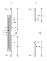
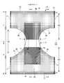
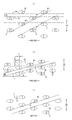
- FIG. 1 is a sectional view taken along the line AA of FIG.
- BB of FIG. It is a cross-sectional view of BB of FIG.
- FIG. 1 is a sectional view taken along the line AA of FIG.
- FIG. 1 is a cross-sectional view of BB of FIG.
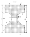
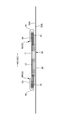
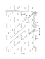
- FIG. 1 is a top view (inner surface side) of the main part of the expansion and contraction area in the pants type disposable diaper in the unfolded state.
- FIG. 1A is a plan view and FIG. 11B is a sectional view taken along line BB of FIG. 11A.
- FIG. 1A is a plan view and FIG. 12B is a sectional view taken along line BB of FIG. 12A.
- FIG. 1A is a plan view
- FIG. 12B is a sectional view taken along line BB of FIG. 12A.
- FIG. 26 It is a comparative explanatory view of the arrangement example of a joint part. It is a plan view (inner surface side) of the pants type disposable diaper in the unfolded state. (A) is a sectional view taken along the line CC of FIG. 26, and (b) is a sectional view taken along the line EE of FIG. 26. It is a plan view (outer surface side) of the pants type disposable diaper in the unfolded state. It is sectional drawing which shows the laminated structure of the colored nonwoven fabric and the lower sheet. It is sectional drawing which shows the laminated structure of the colored nonwoven fabric and the lower sheet.
- the dotted pattern portion in the figure shows an adhesive as a joining means for joining the constituent members located on the front side and the back side, and is a solid, bead, curtain, summit or spiral coating of hot melt adhesive, or
- the fixed portion of the elastic member is formed by pattern coating (transfer of hot melt adhesive by the letterpress method) or by coating the elastic member on the outer peripheral surface of the elastic member such as comb gun or sure wrap coating instead of or together with this. It is a thing.
- the hot melt adhesive include EVA type, adhesive rubber type (elastomer type), olefin type, polyester / polyamide type and the like, but they can be used without particular limitation.
- a means by welding materials such as a heat seal and an ultrasonic seal can also be used.
- non-woven fabric in the following description, a known non-woven fabric can be appropriately used depending on the site and purpose.
- the constituent fibers of the non-woven fabric include olefin-based fibers such as polyethylene and polypropylene, polyester-based and polyamide-based synthetic fibers (including single-component fibers and composite fibers such as core sheaths), as well as recycled rayon and cupra. Fibers, natural fibers such as cotton, and the like can be selected without particular limitation, and these can be mixed and used. In order to increase the flexibility of the non-woven fabric, it is preferable that the constituent fibers are crimped fibers.
- the non-woven fabric generally has a short fiber non-woven fabric, a long fiber non-woven fabric, a spunbond non-woven fabric, a melt blown non-woven fabric, a spunlace non-woven fabric, a thermal bond (air-through) non-woven fabric, and a needle punch depending on the fiber length, the sheet forming method, the fiber bonding method, and the laminated structure.
- Laminated non-woven fabric means that it is manufactured as an integral non-woven fabric including all layers and fiber-bonding processing is performed over all layers, and a plurality of separately manufactured non-woven fabrics are attached by a joining means such as a hot melt adhesive. Does not include combined items.
- FIGS. 1 to 6 show an example of a pants-type disposable diaper (hereinafter, also simply referred to as a diaper).
- the symbol ED indicates the expansion / contraction direction ED of the expansion / contraction region, and in this example, it is in the same direction as the width direction WD of the diaper.
- the reference numeral XD indicates a direction orthogonal to the expansion / contraction direction ED, and in this example, it is the same direction as the front-rear direction LD of the diaper.
- This pants-type disposable diaper has an outer body 20 forming a front body F and a back body B, and an inner body 10 fixed to and integrated with the inner surface of the outer body 20, and the inner body 10 is liquid-permeable.
- the absorber 13 is interposed between the sexual top sheet 11 and the liquid-impermeable sheet 12.
- the waist opening and the left and right sides are formed by folding at the center of the front-rear direction LD (longitudinal direction), which is the boundary between the two, and joining the both side portions to each other by heat welding or hot melt adhesive to form the side seal portion 21.
- LD longitudinal direction
- the interior body 10 has an absorber 13 that absorbs and retains excrement between the liquid-permeable top sheet 11 and the liquid-impermeable sheet 12 made of polyethylene or the like. It has an intervening structure and absorbs and retains the excrement liquid that has passed through the top sheet 11.
- the planar shape of the interior body 10 is not particularly limited, but it is generally substantially rectangular as shown in FIG.
- top sheet 11 that covers the front side (skin side) of the absorber 13 a perforated or non-perforated non-woven fabric, a porous plastic sheet, or the like is preferably used.
- a perforated or non-perforated non-woven fabric a porous plastic sheet, or the like is preferably used.
- urine or the like is quickly absorbed, and the dry touch property is excellent.
- the top sheet 11 wraps around the side edge portion of the absorber 13 and extends to the back side of the absorber 13.
- a liquid-impermeable plastic sheet such as polyethylene or polypropylene is used as the liquid-impermeable sheet 12 that covers the back side (non-skin contact side) of the absorber 13, but in recent years, it has moisture permeability from the viewpoint of preventing stuffiness. Is preferably used.
- This water-impervious / moisture-permeable sheet is a microporous sheet obtained by melt-kneading an inorganic filler in an olefin resin such as polyethylene or polypropylene to form a sheet, and then stretching the sheet in the uniaxial or biaxial direction. is there.
- the absorber 13 is basically a known material, for example, a stack of pulp fibers, an aggregate of filaments such as cellulose acetate, or a non-woven fabric, and is formed by mixing and fixing a highly absorbent polymer as necessary. Can be used.
- the absorber 13 can be wrapped with a wrapping sheet 14 having liquid permeability and liquid retention, such as crepe paper, if necessary, in order to retain the shape and polymer.
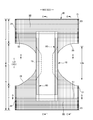
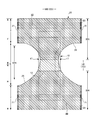
- the shape of the absorber 13 is formed in a substantially hourglass shape having a constricted portion 13N narrower than both front and rear sides in the crotch portion.
- the dimensions of the constricted portion 13N can be appropriately determined, but the length of the constricted portion 13N in the front-rear direction can be about 20 to 50% of the total length of the diaper, and the width of the narrowest portion is 40 of the total width of the absorber 13. It can be about 60%.
- the planar shape of the interior body 10 is substantially rectangular, the portion of the interior body 10 corresponding to the constricted portion 13N of the absorber 13 does not have the absorber 13.
- the absorber side portion 17 is formed.
- the liquid impermeable sheet 12 is folded back together with the top sheet 11 on both sides of the absorber 13 in the width direction.
- the liquid permeable sheet 12 it is desirable to use an opaque sheet so that brown color such as defecation and urine does not appear.
- the opacity a plastic in which pigments such as calcium carbonate, titanium oxide, zinc oxide, white carbon, clay, talc, and barium sulfate and a filler are added and formed into a film is preferably used.
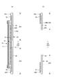
- Three-dimensional gathers 90 that fit around the legs are formed on both sides of the interior body 10.
- the three-dimensional gather 90 has a fixed portion 91 fixed to the side portion of the back surface of the interior body 10, and the interior body 10 from the fixed portion 91 via the side of the interior body 10.
- the main body 92 extending to the side of the surface of the main body and the front and rear ends of the main body 92 are fixed to the side of the surface of the interior body 10 (top sheet 11 in the illustrated example) in an inverted state. It has a portion 93 and a free portion 94 formed so as not to be fixed between the inverted portions 93.
- Each of these parts is formed of a gather sheet 95 made by folding a sheet such as a non-woven fabric into a double sheet.
- the gather sheet 95 is attached to the entire interior body 10 in the front-rear direction, the inverted portion 93 is provided on the front side and the rear side of the non-absorbent body side portion 17, and the free portion 94 is provided on both front and rear sides of the non-absorbent body side portion 17. It has been postponed.
- an elongated gather elastic member 96 is arranged at the tip of a free portion or the like. The gather elastic member 96 is for raising the free portion 94 by the elastic contraction force as shown in FIG. 5 in the product state.
- the gather elastic member 96 is adhesively fixed to the gather sheet 95 and opposed to the gather sheet 95 via a hot melt adhesive at the position of the gather elastic member 96 except for the lodging portion 93.
- the surfaces are joined, in the inverted portion 93, there is no hot melt adhesive at the position of the gather elastic member 96, and therefore the gather elastic member 96 and the gather sheet 95 are not adhered to each other and have the gather elastic member 96.
- the facing surfaces of the gather sheet 95 are not joined at the position.
- the three-dimensional gather 90 shown in FIGS. 5 and 6 is an example in which the main body 92 is not folded back.
- the gather elastic member 96 commonly used materials such as styrene rubber, olefin rubber, urethane rubber, ester rubber, polyurethane, polyethylene, polystyrene, styrene butadiene, silicone, and polyester can be used. Further, in order to make it difficult to see from the outside, it is preferable to dispose of the thickness at 925 dtex or less, the tension at 150 to 350%, and the interval at 7.0 mm or less. As the gather elastic member 96, a tape-shaped member having a certain width can be used in addition to the thread-shaped member as shown in the illustrated example.
- the material of the gather sheet 95 is not limited, but in order to prevent the permeation of urine and the like, prevent fogging, and enhance the feel (dry feeling) to the skin, silicone-based, paraffin metal-based, and alkyl. It is desirable to use a water-repellent treated non-woven fabric coated with a chromic chloride-based water repellent.
- the back surface of the interior body 10 is joined to the inner surface of the exterior body 20 by a hot melt adhesive or the like in the inner / outer fixed region 10B (diagonal line region).
- the inside / outside fixed region 10B can be appropriately defined and can be almost the entire width direction WD of the interior body 10, but it is preferable that both ends in the width direction are not fixed to the exterior body 20.
- the side edge of the exterior body 20 may be located on the center side in the width direction of the side edge of the interior body 10, or may be located on the outside in the width direction.
- the exterior body 20 is a front-rear direction range between the waist circumference portion T corresponding to the side seal portion 21 and the waist circumference portion T of the front body F and the waist circumference portion T of the rear body B. It has an intermediate portion L.
- the planar shape of the exterior body 20 in the illustrated example has a shape similar to an hourglass as a whole, and both side edges in the width direction of the intermediate portion L are constricted so as to form leg openings, but the present invention is limited to this. It's not a thing.
- the exterior body 20 may be individually formed by the front body F and the back body B, and may be arranged so as to be separated from each other in the front-rear direction LD of the diaper at the crotch portion.
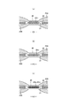
- the exterior body 20 of the illustrated example as shown in FIGS. 2 and 4 to 6, except for the middle portion L in the front-rear direction, between the first sheet layer 20A and the second sheet layer 20B.
- An elastic sheet 30 such as an elastic film is interposed, and as shown in FIG. 9, the first sheet layer 20A and the second sheet layer 20B are formed by a large number of joints 40 arranged at intervals. It has an elastic sheet telescopic structure 20X joined through a joining hole 31 penetrating 30.
- the expansion / contraction direction ED is the width direction WD of the diaper.
- the first sheet layer 20A and the second sheet layer 20B may be indirectly joined through the elastic sheet 30 instead of through the joint hole 31 of the elastic sheet 30.
- FIGS. 1 and 2 are examples in which the elastic sheet telescopic structure 20X extends to the waist end 23, but when the elastic sheet telescopic structure 20X is used for the waist end 23, the waist end 23 If necessary, such as insufficient tightening, the waist end 23 is not provided with the elastic sheet elastic structure 20X as shown in FIGS. 7 and 8, and is expanded and contracted by the conventional elongated waist elastic member 24.
- the waist elastic member 24 is an elongated elastic member such as a plurality of elastic threads arranged at intervals in the front-rear direction LD, and gives an elastic force so as to tighten around the waist of the body.
- the waist elastic members 24 are not substantially arranged as a bundle at close intervals, but are three or more at intervals of about 3 to 8 mm in the front-rear direction so as to form a predetermined expansion / contraction zone. , Preferably 5 or more are arranged.
- the elongation rate at the time of fixing the waist elastic member 24 can be appropriately determined, but in the case of a normal adult, it can be about 230 to 320%.
- thread rubber is used in the illustrated example, but other elongated elastic members such as flat rubber may be used.
- an elastic sheet 30 may be provided at the waist end 23, and an elongated waist elastic member 24 may be provided at a position overlapping the elastic sheet 30 to form an elastic structure composed of both elastic members.
- the edge portion of the leg opening in the exterior body 20 is not provided with an elongated elastic member extending along the leg opening, but is located at a position overlapping the elastic sheet 30 in the edge portion, or the said.
- An elongated elastic member may be provided instead of the elastic sheet 30 at the edge portion.
- the middle portion L between the waist circumference T of the front body F and the waist circumference T of the back body B may have a structure in which the elastic sheet expansion / contraction structure 20X is not provided, or the front body.
- An elastic sheet elastic structure 20X is continuously provided in the front-rear direction LD from the inside of the waist circumference T of F through the middle portion L to the inside of the waist circumference T of the back body B, or either the front body F or the back body B is provided.
- Appropriate deformation is also possible, such as providing an elastic sheet telescopic structure 20X only on the surface.
- the cover sheets 50 and 51 are used for the purpose of reinforcing the exterior body 20 or covering the front and rear ends of the interior body 10 mounted on the inner surface of the exterior body 20. May be provided.
- the front cover sheet 50 extends over the entire width direction WD from the inner surface of the folded portion 20C on the waist side of the inner surface of the front body F to the position where it overlaps with the front end portion of the interior body 10.
- the cover sheet 51 on the rear side extends over the entire width direction WD from the inner surface of the folded portion 20C on the waist side of the inner surface of the rear body B to a position overlapping the rear end portion of the interior body 10.
- attaching the cover sheets 50 and 51 as separate bodies has the advantage of increasing the degree of freedom in material selection, but also has the disadvantage of increasing the number of materials and manufacturing processes. Therefore, the folded portion 20C formed by folding the exterior body 20 to the inner surface of the diaper can be extended to the portion overlapping the interior body 10 to form a portion equivalent to the cover sheets 50 and 51 described above (not shown). ..
- the region of the exterior body 20 having the elastic sheet telescopic structure 20X has a stretchable region that can be stretched in the width direction WD.
- the elastic sheet 30 has a portion 32 (see FIG. 12A) that is linearly continuous along the width direction WD, and contracts in the width direction WD due to the contraction force of the elastic sheet 30. At the same time, it can be extended in the width direction WD. More specifically, in a state where the elastic sheet 30 is extended in the width direction WD, the elastic sheet 30 is separated from each other in the width direction WD and the front-rear direction LD (direction LD orthogonal to the expansion / contraction direction) orthogonal to the width direction WD.
- the front-rear direction LD direction LD orthogonal to the expansion / contraction direction
- the elastic sheet elastic structure 20X is formed by joining the first sheet layer 20A and the second sheet layer 20B through the joint hole 31 to form a large number of joint portions 40, and the elastic sheet 30 is formed in the elastic region 80.
- Such elasticity can be imparted by arranging the joint holes 31 so as to have a portion 32 (see FIG. 12A) that is linearly continuous along the width direction WD.
- FIG. 25 It does not have to have as in the example shown in (b).
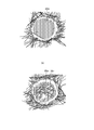
- the stretchable region 80 swells in the direction in which the first sheet layer 20A and the second sheet layer 20B between the joints 40 are separated from each other as shown in FIGS. 9 and 12 (b), and in the front-rear direction.
- the folds 25F extending to the LD are formed, and even in the mounted state in which the folds 25F extend to some extent in the width direction WD, the folds 25F are extended but remain.
- the first sheet layer 20A and the second sheet layer 20B are not joined to the elastic sheet 30 except between the first sheet layer 20A and the second sheet layer 20B at least in the joint portion 40.
- FIG. 9C assuming a mounted state and FIG.
- the elastic sheet 30 A gap is formed between the joint hole 31 and the joint portion 40, and even if the material of the elastic sheet 30 is a non-perforated film or sheet, air permeability is added by this gap. Further, in the natural length state, the joint hole 31 is narrowed due to the further contraction of the elastic sheet 30, and a gap is hardly formed between the joint hole 31 and the joint portion 40.
- the elastic limit elongation of the expansion / contraction region 80 in the width direction WD is 190% or more (preferably 225 to 285%).
- the elastic limit elongation of the elastic region 80 is reduced by a factor that hinders the contraction of the WD in the width direction based on the elongation rate of the elastic sheet 30 at the time of manufacture.
- the elastic limit elongation of the expansion / contraction region 80 can be adjusted by the area ratio of the joint portion 40.
- the elongation stress of the expansion / contraction region 80 has a portion where the elastic sheet 30 is linearly continuous along the width direction WD (separation interval d described later) as shown in the example shown in FIG. 25A described later. In this case, it can be adjusted mainly by the sum of the orthogonal directions (equal to the separation interval d of the joint holes 31) of the portions where the elastic sheet 30 is linearly continuous along the width direction WD.
- the angle ⁇ described later which is a normal case. It is preferable that the angles ⁇ are larger than 0 degrees and 45 degrees or less, particularly in the range of 10 to 30 degrees.
- the area ratio of the joint portion 40 and the area of each joint portion 40 in the expansion / contraction region 80 can be appropriately determined, but usually, it is preferably within the following range.
- Area of joint 40 0.14 to 3.5 mm 2 (particularly 0.14 to 1.0 mm 2 )
- Area ratio of joint 40 1.8 to 19.1% (especially 1.8 to 10.6%)
- the elastic limit elongation and elongation stress of the expansion / contraction region 80 can be adjusted by the area of the joint portion 40, as shown in FIG. 7, a plurality of regions having different area ratios of the joint portion 40 are provided in the expansion / contraction region 80. , The fit can be changed according to the part.
- the edge expansion / contraction region 82 of the leg opening is provided, and the area ratio of the joint portion 40 is higher in the edge expansion / contraction region 82 than in the other regions, and therefore the elongation stress is weak and flexible. It is an area that expands and contracts.
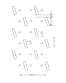
- the shapes of the individual joints 40 and the joint holes 31 in their natural lengths can be appropriately determined, but are perfect circles, ellipses (see FIG. 20D), triangles, rectangles (see FIGS. 9), and rhombuses. It can be a polygon such as (see FIG. 20 (b)), a convex lens shape (see FIG. 20 (a)), a concave lens shape (see FIG. 20 (c)), a star shape, a cloud shape, or any other shape. ..
- the dimensions of the individual joints 40 are not particularly limited, but the maximum length 40y (approximately equal to the dimension 31y in the orthogonal direction of the joint hole 31) is 0.5 to 3.0 mm, particularly 0.7 to 1.1 mm.
- the maximum width of 40x is preferably 0.1 to 3.0 mm, and particularly preferably 0.1 to 1.1 mm in the case of a shape long in the direction XD orthogonal to the expansion / contraction direction.
- the joint hole 31 is mainly related to the shape of the joint portion 40 (41, 42, 43) and the manufacturing stage or the degree of expansion and contraction.
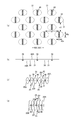
- FIG. 9 is shown as a representative example in Patent Document 1. That is, the joint 40 groups are arranged in a staggered pattern, and the joint 40 is elongated in the direction orthogonal to the expansion / contraction direction and is line-symmetrical with respect to the center line passing through the center of the expansion / contraction direction (left-right symmetry in FIG. 9A). It is said to be in shape.
- the width 40x of the joint portion 40 in the expansion / contraction direction is 0.2 to 0.4 mm
- the distance d1 of the joint portions 40 arranged in the expansion / contraction direction is 3 to 12.9 mm, particularly 5
- the distance d2 of the joints 40 arranged in the direction orthogonal to the expansion / contraction direction is preferably 2 to 10.5 mm, particularly preferably 2.3 to 4.6 mm.
- the length 40y in the direction orthogonal to the expansion / contraction direction of the joint portion 40 is preferably 0.4 to 3.2 mm, particularly preferably 0.7 to 1.4 mm.
- the joints 40 having a remarkably narrow width 40x in the expansion / contraction direction are arranged in a staggered pattern with a somewhat wide separation interval d1 in the expansion / contraction direction, and the contraction force of the elastic sheet 30 is directly applied to each joint 40.
- the arrangement and spacing of the joint portions 40 are firmly maintained at the positions of the joint holes 31 of the elastic sheet 30, and as a result, the flexibility is unlikely to decrease.
- the folds 25f extend almost straight along the direction orthogonal to the expansion / contraction direction, and the joint portion 40 is hidden between the folds 25f and the folds 25f to be inconspicuous. Therefore, the elastic sheet elastic structure 20X has an appearance closer to that of cloth while suppressing a decrease in flexibility.
- the shape of the joints 40 can be circular.
- the shape of the joint portion 40 is elongated in the direction orthogonal to the expansion / contraction direction.
- the maximum length in the direction orthogonal to the expansion / contraction direction of the joint portion 40 is too short or too long, the linearity of the folds 25f may decrease or the flexibility may decrease. Therefore, although these dimensions can be appropriately determined, the length 40y in the direction orthogonal to the expansion / contraction direction of the joint portion 40 is preferably 0.4 to 3.2 mm, particularly 0.7 to 1.4 mm.
- Patent Document 2 in both of the two examples shown in FIGS. 10 (a) and 10 (b), the arrangement of the joint portions of the elastic films (shown by a slightly vertically long rectangle) is also a staggered arrangement (b).
- a small circular sub-joint is arranged between the rectangular main joints.
- the example is also based on the idea of staggered arrangement.
- each joint is preferably within the dimensional range (unit: mm) shown in FIG. 10, mainly in terms of appearance, touch, and breathability.
- the joint length B shown in FIG. 10 is 0.3 to 0.7 mm and the separation interval H is 0.6 to 1.4 mm.
- the joint portion is opened in the width direction as shown in FIG. 9 to form a joint hole 31 only by applying a small extension force in the width direction (expansion / contraction direction of the elastic sheet 30) from the outside.
- the width direction expansion / contraction direction of the elastic sheet 30
- the joints do not exist, so that the extension stress of the elastic sheet 30 becomes a contraction force as it is and tightens the wearer. It is thought that this is because.
- the area ratio occupied by the joint portion and the area ratio occupied by the joint hole in the use state extended in the width direction are high, so that the air permeability is excellent. It also brings the advantage of.
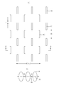
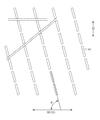
- the joint portion 40 is formed in the expansion / contraction region so as to be separated from the expansion / contraction direction ED and the orthogonal direction XD orthogonal to the expansion / contraction direction ED.
- the joints 40, 40 ... Group of the expansion / contraction region are in a relationship of intersecting the expansion / contraction direction line at each position in the orthogonal direction XD as shown in FIG. 25 (b), or the expansion / contraction direction as shown in FIG. 25 (c).
- the relationship does not intersect with the expansion / contraction direction line
- Predetermined orthogonal XD separation width in the diagonal line group of diagonal lines q intersecting the expansion / contraction direction line within an angle ⁇ range of 45 degrees or less that is, the diagonal line group between diagonal lines q and q in FIG. In the above, the joint group does not intersect the diagonal line.
- the force in the expansion / contraction direction when deployed in the expansion / contraction direction ED when worn propagates while detouring as shown in FIG. 25 (b) (propagation path is indicated by reference numeral S).
- the reason for showing this propagation path S is that the elastic sheet 30 expands and contracts not only in the width direction but also in the orthogonal direction.
- the extension of the expansion / contraction direction ED occurs while forming the joint holes 31 and 31 on both sides of the joint portion 40 in the width direction.
- the contraction force of the elastic sheet causes the joint holes 31 and 31 to contract in the width direction while shortening the opening width (opening length).
- the separation interval d is large, the elastic sheet is not deformed in the separation interval d region, so that the amount (length) of contraction in the width direction is large.
- the joint holes 31 and 31 contract until they are closed. In this case, the air permeability from the openings of the joint holes 31 and 31 may not be sufficiently ensured.
- the elastic sheet 30 is deformed due to the openings of the joint holes 31 and 31 in all or most of the orthogonal directions (so to speak, the elastic sheet is damaged). (In the state of being). As a result, when the extension force in the width direction is released, the opening width (opening length) of the joint holes 31 and 31 once opened is short and the ratio is small, thus ensuring the air permeability from the openings of the joint holes 31 and 31. Will not drop excessively.
- the expansion / contraction direction line and the angle ⁇ of 45 degrees or less are defined as the opening angle between the expansion / contraction direction line and the diagonal line q even in the case of a diagonal line from the upper left to the lower right as shown in FIG. It is a thing.
- the separation interval H along the orthogonal direction XD is 0.2 to 10 mm, more preferably 0.2 to 5.0 mm, and particularly preferably 0.6 to 3.0 mm.
- the opening angle ⁇ between the expansion and contraction direction line and the diagonal line is more preferably 30 degrees or less, particularly preferably 15 degrees or less.
- the joint portion 40 is formed with a width in the expansion / contraction direction of 0.3 to 10.0 mm, preferably 0.5 to 5.0 mm, particularly preferably 0.7 to 3.5 mm.
- the length L of the joint portion 40 in the orthogonal direction XD reference is 0.3 to 7.0 mm, preferably 0.5 to 5.0 mm, and particularly preferably 0.7 to 2.5 mm.
- the formation pitch S0 based on the expansion / contraction direction ED (WD) is 2.0 to 20.0 mm, preferably 3.0 to 15.0 mm, particularly preferably 4.0 to. It is formed at 10.0 mm.
- an elastic sheet is interposed between the breathable first sheet layer and the breathable second sheet layer, and the first sheet layer and the second sheet layer are arranged at intervals. It is provided with an elastic sheet expansion / contraction structure in which a large number of joints are joined through a joint hole penetrating the elastic sheet or through the elastic sheet.
- the elastic region showing the elastic sheet expansion / contraction structure can be expanded / contracted in the expansion / contraction direction by the contraction force of the elastic sheet.
- the joint has the first joints 40, 40 ... And the second joints 41, 41 ...
- the first joints 40, 40 ... are arranged at intervals along the orthogonal direction XD to form a first row of joints.
- the first joint 40, 40 ... Rows are inclined in an angle ⁇ of intersecting the expansion / contraction direction ED in the range of 30 degrees to 150 degrees without following the orthogonal direction XD. (Therefore, 90 degrees is not included), and more preferably, it is tilted in the range of 45 degrees to 135 degrees (90 degrees is not included).
- the intersecting angle ⁇ that is not inclined is 90 degrees.
- the first joint portion 40 is formed with a length L based on the orthogonal direction XD of 0.3 to 7.0 mm, preferably 0.5 to 5.0 mm, and particularly preferably 0.7 to 2.5 mm.
- the formation pitch S0 based on the expansion / contraction direction ED (WD) is 2.0 to 20.0 mm, preferably 3.0 to 15.0 mm, particularly preferably 4.0 to. It is formed at 10.0 mm.
- the percentage is excessively low, the possibility that the first joints 40 and 40 adjacent to the orthogonal XD are continuous in the manufacturing process cannot be excluded, and more fundamentally, the anvil forming the joint and the anvil The heating horn is overloaded with equipment, which may hinder stable operation.
- the following advantages or features are typically shown. (1) Since the above-mentioned percentage is low, the stretching stress in the stretching direction is low, and the stretchable sheet member has a flexible stretch, and when this is applied to an absorbent article, the wearing feeling is excellent. Moreover, since the aperture ratio is high, the air permeability is high.
- the second joint portion 41 Since the second joint portion 41 has an area smaller than that of the first joint portion 40, it looks like a pattern.
- the fact that the inter-row pleats R can be formed between the first joint 40, 40 ... row and the second joint 41, 41 ... row means that the first joint 40, 40 ... row and the first joint 40 can be formed.
- 40 ... means that two row-to-row pleats can be formed between the rows.
- the distance between the second joints 41, 41 is long, which means that pleats can be formed without imposing an excessive equipment burden on the anvil and the heating horn.
- a large number of pleats can be formed with a narrow width per unit area without imposing a facility burden. In this way, the contact area of the wearer with the skin can be reduced, and comfort and softness can be improved.
- the second joint portions 41, 41 ... Group can be arranged between the first joint portions 40, 40 in the orthogonal directions XD. In this case, even if the length L of the first joint portion 40 is short, the stretching stress can be reduced by locating the second joint portion 41.
- the second joint 41 is not adjacent to the first joint 40 on a one-to-one basis, but is, for example, one first joint to two second joints 41 and 41.
- the portions 40, 40 can be arranged adjacent to each other.
- a third joint portion 42, 42 ... row having a long separation interval in the orthogonal direction XD is formed between the first joint portion 40, 40 ... row and the second joint portion 41, 41 ... row. can do.
- the third joint portion 42 By forming the third joint portion 42, the large pleats bf obtained by dividing the inter-row pleats R shown in the first embodiment in the orthogonal direction XD can be formed. Small pleats sf can be formed between the third joint portion 42 and the first joint portions 40, 40 ... Rows.
- the bending rigidity of the elastic member is low (easy to bend), and the followability to the movement of the body is good.
- the fourth joint 43 can be inserted and arranged in the first joint 40, 40 ... Row.
- the fourth joint portions 43, 43 ... Can be arranged diagonally as shown in the figure in addition to along the expansion / contraction direction ED.
- the area of the fourth joint portion 43 is preferably 5% or more and 50% or less of the area of the first joint portion 40.
- the first joint portion 40 itself may be inclined.
- the second joint 41 may also be inclined. Since the joint length is based on the orthogonal direction XD, as shown in FIG. 18, the length L of the first joint 40 is the orthogonal XD length from the center of one side to the center of the other side as the joint length. Become. As for the separation interval, the distance XD in the orthogonal direction between the center of the side and the center of the opposite side is the separation interval d.
- the first joint 40 is inclined, and the row of each joint does not follow the orthogonal direction XD, and the angle ⁇ intersecting the expansion / contraction direction ED is 30 degrees to 150 degrees, preferably 45 degrees to 45 degrees.
- An example of tilting in the range of 135 degrees is shown.
- the angle of intersection ⁇ is particularly preferably 60 to 120 degrees. However, 90 degrees is naturally not included in these angle ranges indicating inclination.
- this joint row is inclined so as to intersect the expansion / contraction direction ED without following the orthogonal direction XD becomes clear when compared with the arrangement example 10 shown in FIG. That is, in the example shown in FIG. 19, for example, the separation interval between the first joints 40, 40 on the orthogonal XD line is considerably larger than that of the arrangement example 10 shown in FIG.
- first sheet layer 20A and the second sheet layer 20B at the joint portion 40 are joined by a joining means such as heat sealing or ultrasonic sealing.
- the seal is melted by ultrasonic waves between the anvil roll and the ultrasonic horn, but in order to prevent energy loss, the ultrasonic horn is also in close contact with the sheet in the entire axial direction of the anvil roll. For this reason, a large ultrasonic output is formed when a pattern having a large proportion of anvil roll protrusions is formed along the bus line in line contact, such as the joints 40, 40 ... Rows in FIG. For this reason, if an excessive close force is applied along the bus line that makes line contact, the burden on the equipment side is large.
- the ratio of the joints located on the line in the orthogonal direction XD is small, and the line pressure is stable, so that the equipment load is small. Therefore, stable operation is possible.
- the first joint portion 40 (and the second joint portion 41) is inclined, it also has an advantage that folds and pleats having excellent design can be formed.
- a non-stretchable region 70 can be provided in the region of the exterior body 20 having the elastic sheet stretchable structure 20X in addition to the stretchable region 80.
- the non-stretchable region 70 means that the elastic limit elongation in the stretch direction is 120% or less.
- the elastic limit elongation of the non-stretchable region 70 is preferably 110% or less, and more preferably 100%.
- the arrangement of the stretchable region 80 and the non-stretchable region 70 can be appropriately determined.
- the non-stretchable region 70 is defined as the non-stretchable region 70) (preferably including almost the entire inner / outer fixed region 10B).
- the non-stretchable region 70 can be provided from the region that overlaps with the absorber 13 to the region that does not overlap with the absorber 13 located in the width direction WD or the front-back direction LD, and the non-stretchable region is provided only in the region that does not overlap with the absorber 13. 70 can also be provided.
- the shape and arrangement of the individual joints 40 in the non-stretchable region 70 and the shape and arrangement of the joint holes 31 in the elastic sheet 30 can be appropriately determined.
- the area ratio of the joint portion 40 and the area of each joint portion 40 in the non-stretchable region can be appropriately determined, but in the normal case, the area of each joint portion 40 is small and the joint portion is within the following range. It is preferable because the non-stretchable region 70 does not become hard due to the low area ratio of 40.
- the non-stretchable region 70 can be formed by densely arranging the joint portions 40 so that the first sheet layer and the second sheet layer do not contract due to the contraction force of the elastic sheet 30 to form folds.
- Specific examples of the method for forming the non-stretchable region 70 include those shown in Japanese Patent No. 5980355, Japanese Patent No. 5918877, Japanese Patent No. 5980367, and Japanese Patent No. 6049228.
- the non-stretchable region 70 is preferably a region in which the elastic sheet 30 is continuous in the width direction WD but does not have a portion linearly continuous along the width direction WD due to the presence of the joint hole 31.
- the first sheet layer 20A and the first sheet layer 20A and the elastic sheet layer 20A and the elastic sheet 30 are spaced through the joint holes 31 of the elastic sheet 30 at intervals in the width direction WD and the front-rear direction LD orthogonal to the width direction WD.
- the non-stretchable region 70 Since the elastic sheet 30 is not linearly continuous along the width direction WD, the contraction force of the elastic sheet 30 hardly acts on the first sheet layer 20A and the second sheet layer 20B, the elasticity is almost lost, and the elastic limit is reached. The growth is close to 100%.
- the first sheet layer 20A and the second sheet layer 20B are joined by a large number of joints 40 arranged at intervals, and the joints 40 are not continuous, so that they are flexible. Deterioration of sex is prevented.
- the joining means of the first sheet layer 20A and the second sheet layer 20B at the joining portion 40 is not particularly limited.
- the first sheet layer 20A and the second sheet layer 20B in the bonding portion 40 may be bonded by a hot melt adhesive or by a bonding means such as heat sealing or ultrasonic sealing.
- the structure in which the joint portion 40 is formed by material welding is the first sheet layer in the joint portion 40.
- a first welded structure in which the first sheet layer 20A and the second sheet layer 20B are joined only by the molten solidified product 20m of at least one of the 20A and the second sheet layer 20B see FIG. 21A.
- a second welded structure in which the first sheet layer 20A and the second sheet layer 20B are joined only by the molten solidified product 30 m of all or most or a part of the elastic sheet 30 at the joint portion 40 see FIG. 21 (b)
- any of the third welded structures in which both of these are combined see FIG. 21 (c)
- the second and third welded structures are preferable.
- the first sheet layer 20A due to a part of the molten solidified product 20 m of the first sheet layer 20A and the second sheet layer 20B and the melted solidified product 30 m of all or most of the elastic sheet 30 at the joint portion 40. And the structure in which the second sheet layer 20B is joined.
- the elastic sheet 30 shown in white is shown between the melt-solidified 20 m of the fibers of the first sheet layer 20A or the second sheet layer 20B shown in black.
- the elastic sheet 30 is formed between the molten solidified products 20 m of the fibers of the first sheet layer 20A or the second sheet layer 20B. No melted solidified material is found.
- the first sheet layer 20A and the second sheet layer 20A and the second sheet layer 20A and the second sheet layer 20A and the second sheet layer 20A and the second sheet layer 20A and the second sheet layer 20B use at least one of at least one of the first sheet layer 20A and the second sheet layer 20B as an adhesive.
- the sheet layer 20B is bonded, it is preferable that a part of the first sheet layer 20A and the second sheet layer 20B is not melted because the bonded portion 40 is not hardened.
- the core (composite) of all the fibers of the joint portion 40 is such that a part of the first sheet layer 20A and the second sheet layer 20B does not melt.
- the surrounding part including not only the sheath of the composite fiber but also the surface layer side part of the single component fiber
- the peel strength becomes high.
- the first sheet layer 20A and the second sheet layer 20B are under the condition that the melting point of at least one of the first sheet layer 20A and the second sheet layer 20B is higher than the melting point of the elastic sheet 30 and the heating temperature at the time of forming the joint portion 40. It can be manufactured by sandwiching the elastic sheet 30 between the second sheet layers 20B, pressurizing and heating the portion to be the joint portion 40, and melting only the elastic sheet 30.
- the melting point of at least one of the first sheet layer 20A and the second sheet layer 20B is higher than the melting point of the elastic sheet 30, between the first sheet layer 20A and the second sheet layer 20B. It can be produced by sandwiching the elastic sheet 30 and pressurizing and heating the portion to be the joint portion 40 to melt at least one of the first sheet layer 20A and the second sheet layer 20B and the elastic sheet 30.
- the melting point of the elastic sheet 30 is preferably about 80 to 145 ° C., and the melting points of the first sheet layer 20A and the second sheet layer 20B are about 85 to 190 ° C., particularly about 150 to 190 ° C.
- the difference between the melting points of the first sheet layer 20A and the second sheet layer 20B and the melting points of the elastic sheet 30 is preferably about 60 to 90 ° C.
- the heating temperature is preferably about 100 to 150 ° C.
- the molten solidified product 30 m of the elastic sheet 30 is the joint portion 40 as shown in FIG. 22 (c).
- the first sheet layer 20A and the second sheet layer 20B may permeate between the fibers over the entire thickness direction, but as shown in FIG. 22A, the structure permeates between the fibers to the middle in the thickness direction, or the figure.
- the structure in which the fibers of the first sheet layer 20A and the second sheet layer 20B hardly permeate between the fibers has a higher flexibility of the joint portion 40.
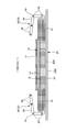
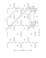
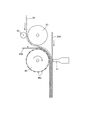
- FIG. 24 shows an example of an ultrasonic sealing device suitable for forming a second welded structure and a third welded structure.
- this ultrasonic sealing device when the joint portion 40 is formed, the first sheet layer 20A and the elastic sheet are formed between the anvil roll 60 having the protrusion 60a formed in the pattern of the joint portion 40 on the outer surface and the ultrasonic horn 61. 30 and the second sheet layer 20B are fed.
- the feed transfer speed of the elastic sheet 30 on the upstream side by the feed drive roll 63 and the nip roll 62 slower than the transfer speed after the anvil roll 60 and the ultrasonic horn 61
- the feed drive roll 63 and the nip roll 62 The elastic sheet 30 is extended to a predetermined elongation rate in the MD direction (machine direction, flow direction) by the path from the nip position by the anvil roll 60 to the seal position by the ultrasonic horn 61.
- the elongation rate of the elastic sheet 30 can be set by selecting the speed difference between the anvil roll 60 and the feed drive roll 63, and can be set to, for example, about 300% to 500%.
- the joint hole 31 is formed from the portions on both sides in the expansion / contraction direction by the joint holes 31. Since it will be cut and lose the support on both sides in the contraction direction, it contracts until the center side of the LD in the direction orthogonal to the expansion / contraction direction ED is balanced with the center side in the expansion / contraction direction within the range where continuity in the direction orthogonal to the contraction direction can be maintained. Then, the joint hole 31 expands in the expansion / contraction direction ED.
- the constituent materials of the first sheet layer 20A and the second sheet layer 20B can be used without particular limitation as long as they are in the form of sheets, but it is preferable to use a non-woven fabric from the viewpoint of breathability and flexibility.
- a non-woven fabric is used, the texture is preferably about 10 to 25 g / m 2 .
- first sheet layer 20A and the second sheet layer 20B may be a pair of layers in which one material is folded back and opposed to each other.
- the constituent material located on the outside is the second sheet layer 20B
- the folded portion 20C formed by folding back to the inner surface side at the waist opening edge is used as the first sheet layer 20A.
- the constituent material located inside is the first sheet layer 20A and the constituent material located outside is the second sheet layer 20B, and the elastic sheet 30 is placed between them. Can be intervened.
- constituent material of the first sheet layer 20A and the constituent material of the second sheet layer 20B are individually provided over the entire front-rear direction LD, and the constituent material of the first sheet layer 20A and the second sheet are not folded back.
- An elastic sheet 30 can also be interposed between the constituent members of the layer 20B.
- the elastic sheet 30 is not particularly limited, and may be an elastic non-woven fabric as well as an elastic film as long as it is a sheet made of a thermoplastic resin that elastically expands and contracts by itself. Further, as the elastic sheet 30, in addition to a non-perforated sheet, a sheet having a large number of holes and slits formed for ventilation can also be used.
- the tensile strength in the width direction WD (extension direction ED, MD direction) is 8 to 25 N / 35 mm
- the tensile strength in the front-rear direction LD (direction XD, CD direction orthogonal to the extension direction) is 5 to 20 N / 35 mm
- the width direction is 8 to 25 N / 35 mm
- the tensile strength in the front-rear direction LD direction XD, CD direction orthogonal to the extension direction
- the elastic sheet 30 has a tensile elongation of 450 to 1050% in the WD and a tensile elongation of 450 to 1400% in the front-rear LD.
- the thickness of the elastic sheet 30 is not particularly limited, but is preferably about 20 to 40 ⁇ m.
- an elastic non-woven fabric may be provided on one side or both sides of the elastic film, and this may be interposed between the first sheet layer 20A and the second sheet layer 20B as the elastic sheet 30.
- the second sheet layer 20B having a portion exposed on the outer surface of the product can be made into a colored non-woven fabric.
- the elastic sheet 30 becomes a lower sheet adjacent to the inside of the colored nonwoven fabric in the region having the elastic sheet elastic structure 20X
- the first sheet layer 20A is adjacent to the inside of the colored nonwoven fabric in the region not having the elastic sheet 30. It becomes the lower sheet.
- the exposed portion of the second sheet layer 20B in the illustrated example is shown by hatching diagonally upward to the left in FIG. 28, and the region where the second sheet layer 20B and the elastic sheet 30 overlap is shown by a dot pattern in FIG. 28. Has been done.
- the second sheet layer 20B most of the outer surface of the product is covered by the second sheet layer 20B.
- the exterior body 20 is individually formed by the front body F and the back body B, and both are arranged so as to be separated from each other in the front-rear direction LD of the diaper at the crotch portion. Since the exterior body 20 is not provided between the exterior body 20 on the front side and the exterior body 20 on the rear side, the exterior non-woven fabric exposed in this portion (the covering sheet 53 described in Patent Document 1 corresponds to this). ) Is a colored non-woven fabric. In this case, the member adjacent to the inside of the colored non-woven fabric is generally a liquid-impermeable sheet 12.
- the absorber 13 it is common to cover the back side of the absorber 13 with a liquid-impermeable sheet 12 such as a waterproof film, and further cover the back side of the liquid-impermeable sheet 12 with an exterior non-woven fabric. Therefore, in this case, it is preferable to use a colored non-woven fabric as the exterior non-woven fabric (not shown).
- the colored non-woven fabric and the lower sheet are not particularly limited, and for example, the top sheet 11 may be a colored non-woven fabric, or the gather sheet 95 may be a colored non-woven fabric.
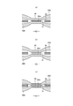
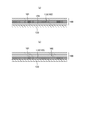
- the colored non-woven fabric 100 is a laminated non-woven fabric in which a plurality of layers are laminated, and the colored layer 110 colored in a first lightness color other than white, in addition to the outermost layer 101.
- the outermost layer 101 preferably has a second lightness color higher than the first lightness.
- the colored non-woven fabric 100 is visually recognized from the outside, the colored layer 110 is seen through the outermost layer 101, so that the color of the colored layer 110 appears to be lightened (brightened).
- the outermost layer 101 naturally has uneven texture, unevenness also occurs in the degree of fading of the visible color of the colored layer 110.
- the color unevenness of the colored layer 110 becomes unexpectedly less noticeable. Therefore, it is possible to make the color unevenness on the appearance of the colored non-woven fabric 100 less noticeable regardless of whether or not the lower sheet 120 is colored.
- the elastic sheet 30 is adjacent to the inside of the colored non-woven fabric 100 in the region having the elastic sheet elastic structure 20X. It becomes the lower sheet 120.
- the joint hole 31 of the elastic sheet 30 also passes through the colored non-woven fabric 100 and becomes visible, which may deteriorate the appearance.
- the elastic sheet elastic structure 20X has the above-mentioned color unevenness prevention structure because not only the color unevenness of the colored nonwoven fabric 100 but also the joint holes 31 become inconspicuous.
- the entire colored nonwoven fabric 100 is colored in a direction orthogonal to the thickness direction, and also overlaps with a part of the region, for example, only the exposed portion or the lower sheet 120. Only the area including the portion may be colored.
- the colored portion is provided in the region having the elastic sheet stretchable structure 20X, the colored portion may be the stretchable region 80 or the non-stretchable region 70.
- the color unevenness caused by the uneven texture of the non-woven fabric starts to be particularly noticeable when the area of the colored portion is about 25 cm 2 , and therefore, when the colored portion has an area larger than this, the above-mentioned color unevenness prevention structure With, the technical significance is particularly great.
- the colored nonwoven fabric 100 may be provided with colored portions of the same color at a plurality of locations at intervals, or may be provided with colored portions of different colors at a plurality of locations at intervals or adjacent to each other. it can.
- the middle portion L and both side portions of the width direction WD can be colored in different colors
- the waist end portion 23 region and the other regions can be colored in different colors.
- the method for producing the colored nonwoven fabric 100 is not particularly limited, but when a single material is colored in a plurality of colors, it can be performed by printing or post-dyeing, and when the entire material is colored in a single color, printing or post-dyeing can be performed.
- Dyeing can be adopted, but a method of mixing a dye or a pigment with a raw material (for example, in the case of a non-woven fabric, a non-woven fabric is formed by a stock solution colored fiber colored by mixing a dye or a pigment with a stock solution before spinning). Is desirable.
- the latter method is preferable in that the presence or absence of coloring of each layer can be easily selected by selecting the presence or absence of coloring for the raw material of each layer of the laminated nonwoven fabric, but the produced colored nonwoven fabric 100 is inevitably the whole. Will be colored in the same color.
- the colored non-woven fabric 100 having only a partially colored portion or colored in a different color. It is possible to manufacture a colored non-woven fabric 100 having a plurality of colored portions.
- the laminated structure of the colored non-woven fabric 100 has a colored layer 110 colored in a first lightness color other than white in addition to the outermost layer 101, and the outermost layer 101 has a higher first lightness than the first lightness. As long as it has a color of 2 lightness, it is not particularly limited.
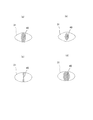
- the colored non-woven fabric 100 has a three-layer structure, as shown in FIG. 29 (a), the second layer 102 is the colored layer 110, and the outermost layer 101 and the innermost layer 103 have the second lightness color.
- the innermost layer 103 is a colored layer 110, and the outermost layers 101 and 102 are non-colored layers having a second lightness color. Can be done.
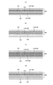
- the second layer 102 and the fourth layer 104 counting from the outside are designated as the colored layer 110, and the first layer (outermost layer 101) is used.
- the third layer 103 are non-colored layers having a second lightness, or as shown in FIG. 30 (b)
- the second layer 102 and the third layer 103 are colored layers 110 and the first layer is counted from the outside.
- the fourth layer 104 may be a non-colored layer having a second lightness.
- all layers 102 to 104 other than the outermost layer are designated as colored layers 110, or as shown in FIG. 30 (d), only one layer is colored in a structure of four or more layers. It can also be layer 110. That is, the number of colored layers 110 and the number of non-colored layers are not limited.
- the color of the first lightness, the color of the second lightness, and the color of the third lightness are not particularly limited.
- the color of the first lightness has a CIELAB L * value of 20 to 90 and a *.
- the absolute value of at least one of the value and the b * value is preferably 0 to 40.
- the colored layer 110 can be colored in beige, gray, pink, blue, purple, yellow, etc., which have a low lightness to some extent.
- the L * value of CIELAB is 60 to 100 for the color of the second lightness.
- the color of the second lightness is preferably white or close to it.
- the absolute value of at least one of the a * value and the b * value of the second lightness color is 0 to 5. It is desirable that the color of the outermost layer 101 of the colored non-woven fabric 100 (that is, the color of the material itself) is within the above range. However, when the colors of the outermost layer 101 and the lower sheet 120 of the colored nonwoven fabric 100 are not within the above range in the non-colored state, the outermost layer 101 of the colored nonwoven fabric 100 is formed by containing a white pigment or the like. The brightness of the color can also be adjusted within the above range.
- the color unevenness of the colored non-woven fabric 100 becomes conspicuous.
- the color of the third lightness is white or close to it, for example, when the absolute value of at least one of the a * value and the b * value of the color of the third lightness is 0 to 5, the color unevenness of the colored non-woven fabric 100 is particularly high. Becomes noticeable. Therefore, particularly in such a case, having the above-mentioned color unevenness prevention structure has a particularly great technical significance.
- the technique Needless to say, the significance of the technology will increase.
- the color of the second lightness and the color of the third lightness may be different colors or similar colors, but in particular, the color of the outermost layer 101 of the colored non-woven fabric 100 and the color of the lower sheet 120 When the colors are close to each other, the effect of preventing color unevenness is high. Therefore, it is preferable that the color difference ⁇ E between the second lightness color and the third lightness color is 30 or less.
- the colored non-woven fabric 100 is preferably a laminated non-woven fabric having 2 to 4 layers having a fineness of 1.5 to 5.0 dtex and a texture of 10 to 20 g / m 2.
- the texture of the non-woven fabric tends to appear as uneven color.
- the color unevenness is small while being flexible.
- Front body and rear body mean the front and rear parts of the pants-type disposable diaper with the center in the front-back direction as the boundary, respectively.
- the crotch portion means a front-rear direction range including the center in the front-rear direction of the pants-type disposable diaper, and when the absorber has a constricted portion, it means the front-rear direction range of the portion having the constricted portion.
- the "front-back direction” means the direction indicated by the symbol LD in the figure (vertical direction)
- the "width direction” means the direction indicated by WD (horizontal direction) in the figure, and the front-back direction and the width direction. Are orthogonal.
- Elastic limit elongation means the elongation of the elastic limit (in other words, the state where the first sheet layer and the second sheet layer are completely expanded) in the expansion / contraction direction ED, and the length at the elastic limit is the natural length. Is expressed as a percentage when is 100%.
- the "area ratio” means the ratio of the target portion to the unit area, and the target portion (for example, the joint portion 40, the opening of the joint hole 31, the ventilation hole) in the target region (for example, the stretchable region 80 and the non-stretchable region 70).
- the total area of is divided by the area of the target area and expressed as a percentage.
- the "area ratio" in the region having a stretchable structure means the area ratio in a state of being stretched to the elastic limit in the stretchable direction ED. It is a thing. When a large number of target portions are provided at intervals, it is desirable to set the target area to a size that includes 10 or more target portions and obtain the area ratio.
- Elongation rate means the value when the natural length is 100%. For example, an elongation rate of 200% is synonymous with an elongation ratio of 2 times.
- ⁇ "Graining" is measured as follows. After pre-drying the sample or test piece, leave it in a test room or device under standard conditions (test location: temperature 23 ⁇ 1 ° C., relative humidity 50 ⁇ 2%) to bring it to a constant weight. Pre-drying refers to constant weight of a sample or test piece in an environment at a temperature of 100 ° C. It is not necessary to pre-dry the fibers having an official moisture content of 0.0%. A sample having a size of 100 mm ⁇ 100 mm is cut out from the test piece in a constant weight state using a sampling template (100 mm ⁇ 100 mm). The weight of the sample is measured and multiplied by 100 to calculate the weight per square meter, which is used as the index.
- the "thickness" other than the above is automatically measured using an automatic thickness measuring device (KES-G5 handy compression measurement program) under the conditions of a load of 0.098 N / cm 2 and a pressurized area of 2 cm 2 .
- KS-G5 handy compression measurement program automatic thickness measuring device
- test piece has a rectangular shape with a width of 35 mm and a length of 80 mm. It means a value measured with an initial chuck interval (distance between marked lines) of 50 mm and a tensile speed of 300 mm / min.
- initial chuck interval distance between marked lines
- tensile speed 300 mm / min.
- AUTOGRAPH AGS-G100N manufactured by SHIMADZU can be used as the tensile tester.
- Elongation stress is defined by a tensile test in which the initial chuck interval (distance between marked lines) is 50 mm and the tensile speed is 300 mm / min according to JIS K7127: 1999 "Plastic-Test method for tensile properties”. , Means the tensile stress (N / 35 mm) measured when stretching in the elastic region, and the degree of stretching can be appropriately determined depending on the test object.
- the test piece is preferably rectangular with a width of 35 mm and a length of 80 mm or more, but if a test piece having a width of 35 mm cannot be cut out, a test piece is prepared with a width that can be cut out, and the measured value is measured with a width of 35 mm.
- L * value, a * value and b * value of "CIELAB” can be measured by, for example, NF555 manufactured by Nippon Denshoku Kogyo Co., Ltd.
- Expanded state means a state in which it is deployed flat without shrinkage or slack.
- the dimensions of each part mean the dimensions in the unfolded state, not in the natural length state.
- the dimensions of the joint portion are the dimensions in the state of being expanded to the limit (the state before the first sheet layer and the second sheet layer are broken), and are substantially the same as the joint portion pattern dimensions in the anvil roll.
- test or measurement shall be performed in a test room or equipment under standard conditions (test location: temperature 23 ⁇ 1 ° C, relative humidity 50 ⁇ 2%). To do.
- the present invention can be used for all disposable diapers such as pants-type disposable diapers as in the above example, various disposable diapers such as tape type and pad type, sanitary napkins, disposable wear articles for swimming and playing in the water, and the like. is there.
Landscapes
- Health & Medical Sciences (AREA)
- Dermatology (AREA)
- Epidemiology (AREA)
- Engineering & Computer Science (AREA)
- Biomedical Technology (AREA)
- Heart & Thoracic Surgery (AREA)
- Vascular Medicine (AREA)
- Life Sciences & Earth Sciences (AREA)
- Animal Behavior & Ethology (AREA)
- General Health & Medical Sciences (AREA)
- Public Health (AREA)
- Veterinary Medicine (AREA)
- Absorbent Articles And Supports Therefor (AREA)
- Laminated Bodies (AREA)
Priority Applications (3)
| Application Number | Priority Date | Filing Date | Title |
|---|---|---|---|
| EP20773043.3A EP3906909A4 (en) | 2019-03-18 | 2020-02-21 | WEARABLE DISPOSABLE |
| US17/422,985 US20220071817A1 (en) | 2019-03-18 | 2020-02-21 | Disposable wearable article |
| CN202080009418.2A CN113301876B (zh) | 2019-03-18 | 2020-02-21 | 一次性穿着物品 |
Applications Claiming Priority (2)
| Application Number | Priority Date | Filing Date | Title |
|---|---|---|---|
| JP2019-050235 | 2019-03-18 | ||
| JP2019050235A JP7121679B2 (ja) | 2019-03-18 | 2019-03-18 | 使い捨て着用物品 |
Publications (1)
| Publication Number | Publication Date |
|---|---|
| WO2020189177A1 true WO2020189177A1 (ja) | 2020-09-24 |
Family
ID=72520201
Family Applications (1)
| Application Number | Title | Priority Date | Filing Date |
|---|---|---|---|
| PCT/JP2020/007035 Ceased WO2020189177A1 (ja) | 2019-03-18 | 2020-02-21 | 使い捨て着用物品 |
Country Status (6)
| Country | Link |
|---|---|
| US (1) | US20220071817A1 (enExample) |
| EP (1) | EP3906909A4 (enExample) |
| JP (1) | JP7121679B2 (enExample) |
| CN (1) | CN113301876B (enExample) |
| TW (1) | TWI807168B (enExample) |
| WO (1) | WO2020189177A1 (enExample) |
Families Citing this family (4)
| Publication number | Priority date | Publication date | Assignee | Title |
|---|---|---|---|---|
| JP7103986B2 (ja) * | 2019-03-18 | 2022-07-20 | 大王製紙株式会社 | 伸縮部材及びこの伸縮部材を有する使い捨て着用物品 |
| JP2023150076A (ja) * | 2022-03-31 | 2023-10-16 | ユニ・チャーム株式会社 | 吸収性物品 |
| KR102666565B1 (ko) * | 2022-06-30 | 2024-05-16 | 섬밋헬스케어 주식회사 | 다층 다색으로 혼합색상이 표출되는 부직포원단의 제조방법 및 그 원단 |
| WO2025187729A1 (ja) * | 2024-03-08 | 2025-09-12 | 株式会社瑞光 | 伸縮性シート及び伸縮性シートの製造方法 |
Citations (9)
| Publication number | Priority date | Publication date | Assignee | Title |
|---|---|---|---|---|
| JPS5918877B2 (ja) | 1976-05-31 | 1984-05-01 | 宏 柊元 | 光半導体素子 |
| JPS6049228B2 (ja) | 1977-06-28 | 1985-10-31 | 株式会社日本触媒 | 新規な結晶形ρ型銅フタロシアニンの製造方法 |
| JP2012170577A (ja) | 2011-02-21 | 2012-09-10 | Nippon Paper Crecia Co Ltd | パンツ型吸収性物品 |
| JP2014226216A (ja) * | 2013-05-20 | 2014-12-08 | 株式会社リブドゥコーポレーション | 吸収性物品 |
| JP2016073578A (ja) | 2014-10-10 | 2016-05-12 | ユニ・チャーム株式会社 | 使い捨ての着用物品 |
| JP5980367B1 (ja) | 2015-03-31 | 2016-08-31 | 大王製紙株式会社 | 吸収性物品の製造方法 |
| JP5980355B2 (ja) | 2015-01-30 | 2016-08-31 | 大王製紙株式会社 | 吸収性物品の伸縮構造、及びこれを用いたパンツタイプ使い捨ておむつ |
| JP2017064132A (ja) * | 2015-09-30 | 2017-04-06 | 大王製紙株式会社 | 吸収性物品 |
| JP2017225508A (ja) | 2016-06-20 | 2017-12-28 | 大王製紙株式会社 | 使い捨て着用物品 |
Family Cites Families (14)
| Publication number | Priority date | Publication date | Assignee | Title |
|---|---|---|---|---|
| CA2045283A1 (en) * | 1991-02-05 | 1992-08-06 | Pi-Chu Nien Hsu | Slat with changing color capability |
| JP2001329473A (ja) * | 2000-05-19 | 2001-11-27 | Kanebo Ltd | 表裏異色染め布帛の製造方法 |
| EP1434543A1 (en) * | 2001-08-03 | 2004-07-07 | Asahi Kasei Life & Living Corporation | Color masking component for use with feminine sanitary pad and the like |
| US20030044578A1 (en) * | 2001-08-14 | 2003-03-06 | Nissing Nicholas James | Printed substrate with variable local attributes |
| US8273066B2 (en) * | 2003-07-18 | 2012-09-25 | Kimberly-Clark Worldwide, Inc. | Absorbent article with high quality ink jet image produced at line speed |
| CN100595378C (zh) * | 2003-12-02 | 2010-03-24 | 大王制纸株式会社 | 着色卫生薄纸及其制造方法 |
| EP2882585B1 (en) * | 2012-08-13 | 2021-03-31 | The Procter and Gamble Company | Multilayered nonwoven webs with visually distinct bond sites and method of making |
| JP6364213B2 (ja) * | 2014-03-27 | 2018-07-25 | ユニ・チャーム株式会社 | 吸収性物品 |
| JP6571323B2 (ja) * | 2014-10-07 | 2019-09-04 | ユニ・チャーム株式会社 | 使い捨ての着用物品 |
| JP6418637B2 (ja) * | 2014-11-18 | 2018-11-07 | 株式会社リブドゥコーポレーション | 吸収性物品 |
| JP2017070587A (ja) * | 2015-10-08 | 2017-04-13 | 花王株式会社 | パンツ型使い捨ておむつ |
| WO2017074422A1 (en) * | 2015-10-30 | 2017-05-04 | Kimberly-Clark Worldwide, Inc. | Absorbent article with channels and shaping elastic members |
| US20170290713A1 (en) * | 2016-04-07 | 2017-10-12 | The Procter & Gamble Company | Absorbent articles comprising graphics |
| JP6381588B2 (ja) * | 2016-07-07 | 2018-08-29 | ユニ・チャーム株式会社 | 吸収性物品 |
-
2019
- 2019-03-18 JP JP2019050235A patent/JP7121679B2/ja active Active
-
2020
- 2020-02-19 TW TW109105298A patent/TWI807168B/zh active
- 2020-02-21 EP EP20773043.3A patent/EP3906909A4/en not_active Withdrawn
- 2020-02-21 US US17/422,985 patent/US20220071817A1/en not_active Abandoned
- 2020-02-21 WO PCT/JP2020/007035 patent/WO2020189177A1/ja not_active Ceased
- 2020-02-21 CN CN202080009418.2A patent/CN113301876B/zh active Active
Patent Citations (9)
| Publication number | Priority date | Publication date | Assignee | Title |
|---|---|---|---|---|
| JPS5918877B2 (ja) | 1976-05-31 | 1984-05-01 | 宏 柊元 | 光半導体素子 |
| JPS6049228B2 (ja) | 1977-06-28 | 1985-10-31 | 株式会社日本触媒 | 新規な結晶形ρ型銅フタロシアニンの製造方法 |
| JP2012170577A (ja) | 2011-02-21 | 2012-09-10 | Nippon Paper Crecia Co Ltd | パンツ型吸収性物品 |
| JP2014226216A (ja) * | 2013-05-20 | 2014-12-08 | 株式会社リブドゥコーポレーション | 吸収性物品 |
| JP2016073578A (ja) | 2014-10-10 | 2016-05-12 | ユニ・チャーム株式会社 | 使い捨ての着用物品 |
| JP5980355B2 (ja) | 2015-01-30 | 2016-08-31 | 大王製紙株式会社 | 吸収性物品の伸縮構造、及びこれを用いたパンツタイプ使い捨ておむつ |
| JP5980367B1 (ja) | 2015-03-31 | 2016-08-31 | 大王製紙株式会社 | 吸収性物品の製造方法 |
| JP2017064132A (ja) * | 2015-09-30 | 2017-04-06 | 大王製紙株式会社 | 吸収性物品 |
| JP2017225508A (ja) | 2016-06-20 | 2017-12-28 | 大王製紙株式会社 | 使い捨て着用物品 |
Also Published As
| Publication number | Publication date |
|---|---|
| CN113301876B (zh) | 2022-04-19 |
| CN113301876A (zh) | 2021-08-24 |
| JP7121679B2 (ja) | 2022-08-18 |
| EP3906909A4 (en) | 2022-09-07 |
| TWI807168B (zh) | 2023-07-01 |
| JP2020151025A (ja) | 2020-09-24 |
| TW202034880A (zh) | 2020-10-01 |
| US20220071817A1 (en) | 2022-03-10 |
| EP3906909A1 (en) | 2021-11-10 |
Similar Documents
| Publication | Publication Date | Title |
|---|---|---|
| JP6723087B2 (ja) | 使い捨て着用物品 | |
| KR102512662B1 (ko) | 신축 부재 및 이 신축 부재를 갖는 일회용 착용 물품 | |
| KR102516436B1 (ko) | 신축 부재 및 이 신축 부재를 갖는 일회용 착용 물품 | |
| WO2018061419A1 (ja) | 使い捨て着用物品及びその製造方法 | |
| JP6331199B2 (ja) | 吸収性物品 | |
| JP6240701B2 (ja) | パンツタイプ使い捨ておむつ | |
| WO2020189177A1 (ja) | 使い捨て着用物品 | |
| JP2017064225A5 (enExample) | ||
| JP2017176494A5 (enExample) | ||
| KR102586585B1 (ko) | 신축 부재 및 이 신축 부재를 갖는 일회용 착용 물품 | |
| JP6739962B2 (ja) | パンツタイプ使い捨ておむつ | |
| WO2019235244A1 (ja) | 使い捨て着用物品 | |
| JP7103986B2 (ja) | 伸縮部材及びこの伸縮部材を有する使い捨て着用物品 | |
| JP6276215B2 (ja) | パンツタイプ使い捨ておむつ | |
| JP2020151868A5 (enExample) | ||
| JP2016187387A5 (enExample) | ||
| KR102519499B1 (ko) | 신축 부재 및 이 신축 부재를 갖는 일회용 착용 물품 | |
| JP5956667B1 (ja) | パンツタイプ使い捨ておむつ | |
| JP6681866B2 (ja) | 伸縮部材及びこの伸縮部材を有するパンツタイプ使い捨て着用物品 | |
| WO2022034729A1 (ja) | 使い捨て着用物品 | |
| WO2020195424A1 (ja) | パンツタイプ使い捨て着用物品及びその製造方法 | |
| JP2019166217A5 (enExample) | ||
| JP6546310B1 (ja) | 伸縮部材及びこの伸縮部材を有する使い捨て着用物品 | |
| WO2021084764A1 (ja) | 伸縮部材及びこの伸縮部材を有する使い捨て着用物品 |
Legal Events
| Date | Code | Title | Description |
|---|---|---|---|
| 121 | Ep: the epo has been informed by wipo that ep was designated in this application |
Ref document number: 20773043 Country of ref document: EP Kind code of ref document: A1 |
|
| ENP | Entry into the national phase |
Ref document number: 2020773043 Country of ref document: EP Effective date: 20210802 |
|
| NENP | Non-entry into the national phase |
Ref country code: DE |