WO2020189174A1 - ライダー装置 - Google Patents
ライダー装置 Download PDFInfo
- Publication number
- WO2020189174A1 WO2020189174A1 PCT/JP2020/006961 JP2020006961W WO2020189174A1 WO 2020189174 A1 WO2020189174 A1 WO 2020189174A1 JP 2020006961 W JP2020006961 W JP 2020006961W WO 2020189174 A1 WO2020189174 A1 WO 2020189174A1
- Authority
- WO
- WIPO (PCT)
- Prior art keywords
- light
- unit
- laser light
- laser
- light receiving
- Prior art date
- Legal status (The legal status is an assumption and is not a legal conclusion. Google has not performed a legal analysis and makes no representation as to the accuracy of the status listed.)
- Ceased
Links
Images

Classifications
-
- G—PHYSICS
- G01—MEASURING; TESTING
- G01S—RADIO DIRECTION-FINDING; RADIO NAVIGATION; DETERMINING DISTANCE OR VELOCITY BY USE OF RADIO WAVES; LOCATING OR PRESENCE-DETECTING BY USE OF THE REFLECTION OR RERADIATION OF RADIO WAVES; ANALOGOUS ARRANGEMENTS USING OTHER WAVES
- G01S17/00—Systems using the reflection or reradiation of electromagnetic waves other than radio waves, e.g. lidar systems
- G01S17/02—Systems using the reflection of electromagnetic waves other than radio waves
- G01S17/06—Systems determining position data of a target
- G01S17/08—Systems determining position data of a target for measuring distance only
- G01S17/32—Systems determining position data of a target for measuring distance only using transmission of continuous waves, whether amplitude-, frequency-, or phase-modulated, or unmodulated
- G01S17/34—Systems determining position data of a target for measuring distance only using transmission of continuous waves, whether amplitude-, frequency-, or phase-modulated, or unmodulated using transmission of continuous, frequency-modulated waves while heterodyning the received signal, or a signal derived therefrom, with a locally-generated signal related to the contemporaneously transmitted signal
-
- G—PHYSICS
- G01—MEASURING; TESTING
- G01S—RADIO DIRECTION-FINDING; RADIO NAVIGATION; DETERMINING DISTANCE OR VELOCITY BY USE OF RADIO WAVES; LOCATING OR PRESENCE-DETECTING BY USE OF THE REFLECTION OR RERADIATION OF RADIO WAVES; ANALOGOUS ARRANGEMENTS USING OTHER WAVES
- G01S7/00—Details of systems according to groups G01S13/00, G01S15/00, G01S17/00
- G01S7/48—Details of systems according to groups G01S13/00, G01S15/00, G01S17/00 of systems according to group G01S17/00
- G01S7/481—Constructional features, e.g. arrangements of optical elements
Definitions
- This disclosure relates to a rider device.
- a lidar (LIDAR: Light Detection and Ringing) device that detects the presence position of an object by emitting laser light and measuring the time until the reflected light reflected by the object is received is known (for example, See Patent Document 1).
- this type of rider device there is a request to improve the S / N ratio in order to improve the maximum detection distance.
- this type of lidar device detects an object by using a laser beam having a wavelength close to the wavelength band of sunlight (for example, about 500 nm to 2000 nm), S is caused by ambient light such as sunlight.
- the / N ratio may deteriorate significantly.
- the present disclosure has been made in view of the above problems, and an object of the present disclosure is to provide a rider device capable of ensuring a high S / N ratio even in an environment where ambient light is present.
- a floodlight that emits laser light and A light receiving unit that generates a received signal by receiving the reflected light reflected by the object from the laser light.
- a scanning unit that has a reflecting material that reflects the laser light emitted from the light projecting unit and scans a predetermined area with the laser light by driving the reflecting material.
- Signal processing that generates a chirp-like time-varying high-frequency signal that drives the light projecting unit and measures the distance from the lidar device to the object according to the FMCW method based on the received signal acquired from the light receiving unit.
- Department and It is a rider device equipped with.
- the rider device According to the rider device according to the present disclosure, it is possible to secure a high S / N ratio even in an environment where ambient light is present.
- the figure which shows the whole structure of the rider device which concerns on one Embodiment The figure which shows the schematic structure of the light emitting part, the light receiving part, and the scanning part of the lidar device which concerns on one Embodiment.
- the figure which shows the mode of scanning in the scanning part which concerns on one Embodiment The figure which shows the structure of the scanning part which concerns on the modification
- the figure which shows the structure of the light receiving sensor which concerns on one Embodiment The figure which shows the structure of the signal processing part which concerns on one Embodiment
- FIG. 1 is a diagram showing an overall configuration of the rider device 1 according to the present embodiment.
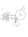
- FIG. 2 is a diagram showing a schematic configuration of a light emitting unit 200, a light receiving unit 300, and a scanning unit 400 of the rider device 1 according to the present embodiment.
- the rider device 1 includes a signal processing unit 100, a light emitting unit 200, a light receiving unit 300, and a scanning unit 400.
- the light projecting unit 200 includes a laser light source 210 that emits laser light L, and a collimator lens 220 that converts laser light L emitted from the laser light source 210 into parallel light rays (see FIG. 2).
- the laser light L emitted by the laser light source 210 has a wavelength band of 1400 nm or more and 2000 nm or less (so-called eye safe band wavelength). Near-infrared rays of the eye-safe band wavelength have a large threshold intensity that causes damage to the eyes. Therefore, it is possible to emit high-intensity laser light L from the laser light source 210.
- the laser light source 210 continuously emits the laser light L while changing the radiation frequency of the laser light L in time based on the drive signal output from the signal processing unit 100 (see FIG. 7 described later). ..
- the radiation frequency of the laser light L emitted by the laser light source 210 is controlled so as to change with time in a chirp shape. That is, the laser light source 210 emits the FMCW (Frequency Modulated Continuous Wave) type laser beam L.
- FMCW Frequency Modulated Continuous Wave
- the laser light source 210 is preferably a semiconductor laser or a fiber laser from the viewpoint of being compact and capable of high output.
- the semiconductor laser it is desirable to use an end face emission method or a VCSEL (Vertical Cavity Surface Emitting LASER). Since the VCSEL can emit a laser beam L having a small beam diameter due to its configuration, it is possible to adopt a configuration in which the collimating lens 220 is not used when the VCSEL is used.
- the fiber laser for example, an erbium fiber laser can be mentioned.
- the laser light L emitted from the laser light source 210 is collimated by the collimator lens 220, converted into parallel light rays, and emitted to the scanning unit 400.
- the scanning unit 400 has a reflector 410 that reflects the laser beam L emitted from the light projecting unit 200, and by driving the reflector 410, the laser beam L causes a predetermined region (hereinafter, “measurement target region”). Also referred to as). That is, the scanning unit 400 widens the angle at which light can be projected and received, and enables light projection and light reception over a wide range.
- the reflective material 410 for example, a polygon mirror, a MEMS mirror, or the like is used.
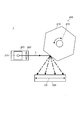
- FIG. 3 is a diagram showing a mode of scanning in the scanning unit 400 according to the present embodiment.
- a polygon mirror is used as the reflective material 410 according to the present embodiment.
- the scanning unit 400 rotates the reflector 410 around the shaft member 420, so that the laser light L emitted from the light projecting unit 200 is reflected by the reflector 410. Then, the direction of being sent out to the outside of the lidar device 1 (hereinafter, referred to as "the direction of sending the laser beam L") is changed with time. As a result, the scanning unit 400 shifts the transmission direction of the laser beam L so as to scan the measurement target area.
- FIG. 3 shows an embodiment in which the transmission direction of the laser beam L is shifted along the scanning direction D1 by rotating the reflective material 410.
- the reflected light S in which the laser light L is reflected by the object 500 reaches the light receiving unit 300 via the reflector 410 in substantially the same path as the laser light L emitted from the light projecting unit 200.
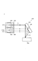
- FIG. 4 is a diagram showing a configuration of a scanning unit 400 according to a modified example.
- FIG. 4 shows an embodiment in which a MEMS mirror is used as the reflective material 410.
- the scanning unit 400 according to the modified example changes the sending direction of the laser beam L in time by rotating the angle of the flat plate-shaped reflector 410 around the shaft member 420.
- the scanning unit 400 has a configuration in which the reflector 410 is driven to perform laser scanning, laser scanning is performed over a wide range as compared with the mode of laser scanning by electronic scanning. It is possible.
- the light receiving unit 300 is a light receiving sensor 310 in which the laser light L receives the reflected light S reflected by the object 500 to generate a received signal, and the light receiving sensor 310 receives the reflected light S reflected by the laser light L in the object 500.
- a condensing lens 320 that collects light on the light receiving surface 310s is provided.
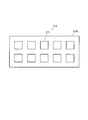
- FIG. 5 is a diagram showing the configuration of the light receiving sensor 310 according to the present embodiment.
- the light receiving sensor 310 generates a received signal by receiving the reflected light S reflected by the object 500 by the laser light L transmitted from the scanning unit 400.
- the light receiving surface 310s of the light receiving sensor 310 is formed by arranging a plurality of light receiving elements 311 in an array from the viewpoint of increasing the spatial resolution.
- the light receiving element 311 is, for example, a photodiode or a phototransistor.
- the light receiving element 311 is typically made of a material having sensitivity to laser light in a wavelength band of 1400 nm or more and 2000 nm or less so as to correspond to the wavelength band of the laser light L emitted from the light projecting unit 200. ..
- a SiGe light receiving element is used as the light receiving element 311 from the viewpoint of ensuring high light receiving sensitivity and good response characteristics.
- the light receiving element 311 is an avalanche type SiGe light receiving element formed by laminating an amplification layer containing silicon and an absorption layer containing germanium on a substrate in this order. Suitable. This makes it possible to secure a high S / N ratio. Further, as a result, unlike the conventionally known InGaAs light receiving element or the like, it is possible to produce a silicon wafer having a large wafer size, and a monolithic device can be configured in the silicon wafer together with other circuit components. ..
- the avalanche type SiGe light receiving element refer to Non-Patent Document 1, for example.
- the light receiving element 311 an InGaAs light receiving element having sensitivity to laser light in a wavelength band of 1400 nm or more and 2000 nm or less, a Ge light receiving element, or the like may be used.
- the signal processing unit 100 generates a chirp-like time-varying high-frequency signal that drives the light projecting unit 200, and based on the received signal acquired from the light receiving unit 300, the distance from the lidar device 1 to the object 500 according to the FMCW method. To measure. Then, the signal processing unit 100 generates a distance image related to the measurement target region scanned by the laser beam L based on the measurement data (for example, distance and reflection intensity) at each scanning position.
- the measurement data for example, distance and reflection intensity
- a TOF (time-of-flight) method has been used when detecting an object position.
- a pulsed laser beam is emitted from the laser light source, and the laser beam emitted from the laser light source is generated based on a temporal change in the signal intensity of the received signal generated by the light receiving sensor.
- the TOF method has a problem that it is easily affected by noise caused by ambient light contained in the received signal and a sufficient S / N ratio cannot be secured.
- a light receiving element having a light receiving sensitivity in the eye safe wavelength band has a larger noise than a general Si light receiving element, so that the S / N ratio is lowered and the maximum detection distance required for the rider device cannot be realized. There is a risk.
- the rider device 1 measures the distance from itself to the object 500 by the FMCW method in order to suppress the deterioration of the S / N ratio due to the ambient light, and generates a distance image.
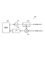
- FIG. 6 is a diagram showing the configuration of the signal processing unit 100 according to the present embodiment.
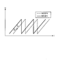
- FIG. 7 is a diagram showing a high frequency signal generated by the signal processing unit 100 according to the present embodiment.
- the solid line represents the drive signal for driving the light projecting unit 200
- the dotted line represents the received signal generated by the light receiving unit 300.
- the signal processing unit 100 includes, for example, an oscillator 101, a distributor 102, a mixer 103, a filter 104, and a calculation unit 105.
- the oscillator 101 generates a high-frequency signal for driving the light projecting unit 200.
- the distributor 102 distributes the high frequency signal generated by the oscillator 101 to a drive signal (that is, a signal transmitted to the light projecting unit 200) and a local signal (that is, a signal transmitted to the mixer 103).
- the mixer 103 generates a beat signal by mixing the received signal acquired from the light receiving unit 300 with the local signal.
- the filter 104 removes unnecessary signal components (typically high frequency components) from the beat signal generated by the mixer 103.
- the calculation unit 105 controls the oscillator 101 so that the frequency of the high-frequency signal generated by the oscillator 101 changes with time in a chirp shape (see FIG. 7).
- the high-frequency signal generated by the oscillator 101 is, for example, a chirp signal whose frequency monotonically increases in a predetermined frequency band over time, and the chirp signal is repeated in a predetermined period. There is.
- the calculation unit 105 acquires the beat signal transmitted from the filter 104 and frequency-analyzes the beat signal. Then, the calculation unit 105 determines the time from the frequency of the beat signal (see fb in FIG. 7) until the laser light L emitted from the laser light source 210 is reflected by the object 500 and returned to the lidar device 1. (See ⁇ t in FIG. 7) is calculated, and the distance from the lidar device 1 to the object 500 is calculated based on this time.
- the calculation unit 105 executes the same processing at each scanning position when the scanning unit 400 laser scans the measurement target area. At this time, it is desirable that the calculation unit 105 emits the laser beam L for at least one cycle of the chirp signal at each scanning position so that the beat signal can be appropriately detected at each scanning position. In other words, it is desirable that the scanning unit 400 changes the scanning position while providing a waiting time for at least one cycle of the chirp signal.
- the calculation unit 105 After performing such laser scanning, the calculation unit 105 performs a distance image (also referred to as point group data) relating to the measurement target region scanned by the laser beam L based on the measurement data (for example, distance and reflection intensity) at each scanning position. To be generated).
- a distance image also referred to as point group data
- the measurement data for example, distance and reflection intensity
- the arithmetic unit 105 is mainly composed of a well-known microcomputer, and is provided with an arithmetic processing unit (for example, DSP) for executing a fast Fourier transform (FFT) process or the like.
- DSP arithmetic processing unit
- FFT fast Fourier transform
- Each function of the arithmetic unit 105 may be realized by processing by software, or may be realized by a dedicated hardware circuit.
- the distance from the rider device 1 to the object 500 is measured by the FMCW method.
- the FMCW method unlike the TOF method, the distance from the lidar device 1 to the object 500 is measured based on the frequency component included in the received signal.
- the lidar device 1 As an example of the lidar device 1, a mode is shown in which a laser beam L having a wavelength band of 1400 nm or more and 2000 nm or less (near infrared rays having an eye-safe band wavelength) is used.
- the lidar device 1 according to the present invention can also be applied to a laser beam L other than the eye-safe band wavelength, for example, a laser beam L having a wavelength band (infrared ray) of 700 nm or more and 1400 nm or less.
- the light receiving element 311 for example, a light receiving element such as Si or Ge can be used.
- the rider device According to the rider device according to the present disclosure, it is possible to secure a high S / N ratio even in an environment where ambient light is present.
Landscapes
- Engineering & Computer Science (AREA)
- Physics & Mathematics (AREA)
- Computer Networks & Wireless Communication (AREA)
- General Physics & Mathematics (AREA)
- Radar, Positioning & Navigation (AREA)
- Remote Sensing (AREA)
- Electromagnetism (AREA)
- Optical Radar Systems And Details Thereof (AREA)
Abstract
本開示は、外乱光が存在する環境下においても、高いS/N比を確保し得るライダー装置を提供することを目的とする。 本開示に係るライダー装置(1)は、レーザー光(L)を出射する投光部(200)と、レーザー光(L)が物体(500)にて反射された反射光(S)を受光して受信信号を生成する受光部(300)と、投光部(200)から出射されたレーザー光(L)を反射する反射材(410)を有し、当該反射材(410)を駆動することで、レーザー光(L)により、所定領域を走査する走査部(400)と、投光部(200)を駆動するチャープ状に時間変化する高周波信号を生成すると共に、受光部(300)から取得する受信信号に基づいて、FMCW方式に従って当該ライダー装置(1)から物体(500)までの距離を測定する信号処理部(100)と、を備える。
Description
本開示は、ライダー装置に関する。
レーザー光を出射し、物体で反射された反射光を受光するまでの時間を計測することにより、物体の存在位置を検出するライダー(LIDAR:Light Detection and Ranging)装置が知られている(例えば、特許文献1を参照)。
この種のライダー装置においては、最大検知距離を向上するため、S/N比を向上させる要請がある。特に、この種のライダー装置は、太陽光の波長帯域に近い波長のレーザー光(例えば、500nm~2000nm程度)を用いて、物体検出を行うため、太陽光等の外乱光に起因して、S/N比が顕著に悪化する場合がある。
本開示は、上記問題点に鑑みてなされたもので、外乱光が存在する環境下においても、高いS/N比を確保し得るライダー装置を提供することを目的とする。
前述した課題を解決する主たる本開示は、
レーザー光を出射する投光部と、
前記レーザー光が物体にて反射された反射光を受光して受信信号を生成する受光部と、
前記投光部から出射された前記レーザー光を反射する反射材を有し、当該反射材を駆動することで、前記レーザー光により、所定領域を走査する走査部と、
前記投光部を駆動するチャープ状に時間変化する高周波信号を生成すると共に、前記受光部から取得する前記受信信号に基づいて、FMCW方式に従って当該ライダー装置から前記物体までの距離を測定する信号処理部と、
を備えるライダー装置である。
レーザー光を出射する投光部と、
前記レーザー光が物体にて反射された反射光を受光して受信信号を生成する受光部と、
前記投光部から出射された前記レーザー光を反射する反射材を有し、当該反射材を駆動することで、前記レーザー光により、所定領域を走査する走査部と、
前記投光部を駆動するチャープ状に時間変化する高周波信号を生成すると共に、前記受光部から取得する前記受信信号に基づいて、FMCW方式に従って当該ライダー装置から前記物体までの距離を測定する信号処理部と、
を備えるライダー装置である。
本開示に係るライダー装置によれば、外乱光が存在する環境下においても、高いS/N比を確保することが可能である。
以下に添付図面を参照しながら、本開示の好適な一実施形態について詳細に説明する。尚、本明細書及び図面において、実質的に同一の機能を有する構成要素については、同一の符号を付することにより重複説明を省略する。
図1は、本実施形態に係るライダー装置1の全体構成を示す図である。図2は、本実施形態に係るライダー装置1の投光部200、受光部300、及び走査部400の概略構成を示す図である。
ライダー装置1は、信号処理部100、投光部200、受光部300、及び、走査部400を備えている。
[投光部]
投光部200は、レーザー光Lを出射するレーザー光源210と、レーザー光源210から出射されたレーザー光Lを平行光線に変換するコリメーターレンズ220とを備える(図2を参照)。
投光部200は、レーザー光Lを出射するレーザー光源210と、レーザー光源210から出射されたレーザー光Lを平行光線に変換するコリメーターレンズ220とを備える(図2を参照)。
レーザー光源210が出射するレーザー光Lは、1400nm以上で且つ2000nm以下の波長帯域(いわゆるアイセーフ帯波長)であるのが望ましい。アイセーフ帯波長の近赤外線は、目に障害を発生させる閾値強度が大きい。そのため、レーザー光源210から高い強度のレーザー光Lを出射することが可能である。
レーザー光源210は、信号処理部100から出力される駆動信号に基づいて、レーザー光Lの放射周波数を時間的に変化させながら、連続的にレーザー光Lを出射する(後述する図7を参照)。レーザー光源210が出射するレーザー光Lの放射周波数は、チャープ状に時間変化するように制御される。即ち、レーザー光源210は、FMCW(Frequency Modulated Continuous Wave)方式のレーザー光Lを出射する。
レーザー光源210は、小型で且つ高出力が可能であるという観点から、半導体レーザー又はファイバーレーザーであることが望ましい。半導体レーザーとしては、端面発光方式又はVCSEL(Vertical Cavity Surface Emitting LASER)を用いることが望ましい。尚、VCSELは、その構成上、ビーム径の小さいレーザー光Lを出射することが可能であるため、VCSELを用いる場合には、コリメートレンズ220を使用しない構成をとることも可能である。又、ファイバーレーザーとしては、例えば、エルビウムファイバーレーザーが挙げられる。
尚、コリメートレンズ220が必要なレーザー光源210の場合には、レーザー光源210から出射されたレーザー光Lは、コリメーターレンズ220でコリメートされ、平行光線に変換され、走査部400に出射される。
[走査部]
走査部400は、投光部200から出射されたレーザー光Lを反射する反射材410を有し、当該反射材410を駆動することで、レーザー光Lにより、所定領域(以下、「測定対象領域」とも称する)を走査する。即ち、走査部400は、投光及び受光可能な角度を広げ、広範囲への投光及び受光を可能とする。
走査部400は、投光部200から出射されたレーザー光Lを反射する反射材410を有し、当該反射材410を駆動することで、レーザー光Lにより、所定領域(以下、「測定対象領域」とも称する)を走査する。即ち、走査部400は、投光及び受光可能な角度を広げ、広範囲への投光及び受光を可能とする。
反射材410としては、例えば、ポリゴンミラー又はMEMSミラー等が用いられる。
図3は、本実施形態に係る走査部400における走査の態様を示す図である。
本実施形態に係る反射材410としては、ポリゴンミラーが用いられている。走査部400は、図3に示すように、反射材410を、軸部材420を中心にして回動することによって、投光部200から出射されたレーザー光Lが、当該反射材410にて反射して、ライダー装置1の外部に送出される方向(以下、「レーザー光Lの送出方向」と称する)を時間的に変化させる。これによって、走査部400は、測定対象領域を走査するように、レーザー光Lの送出方向をシフトさせる。図3では、反射材410を回動させることによって、走査方向D1に沿って、レーザー光Lの送出方向をシフトさせている態様を示している。
尚、レーザー光Lが物体500で反射された反射光Sは、投光部200から出射されたレーザー光Lと略同一の経路で、反射材410を介して、受光部300に至る。
図4は、変形例に係る走査部400の構成を示す図である。図4には、反射材410としてMEMSミラーを用いた態様を示している。変形例に係る走査部400は、平板形状の反射材410の角度を、軸部材420を中心にして回動させることによって、レーザー光Lの送出方向を時間的に変化させる。
尚、本実施形態に係る走査部400は、反射材410を駆動して、レーザー走査する構成を有するため、電子走査により、レーザー走査する態様と比較して、広範囲に亘ってレーザー走査を実行することが可能である。
[受光部]
受光部300は、レーザー光Lが物体500で反射された反射光Sを受光して受信信号を生成する受光センサ310と、レーザー光Lが物体500で反射された反射光Sを受光センサ310の受光面310sに集光する集光レンズ320とを備える。
受光部300は、レーザー光Lが物体500で反射された反射光Sを受光して受信信号を生成する受光センサ310と、レーザー光Lが物体500で反射された反射光Sを受光センサ310の受光面310sに集光する集光レンズ320とを備える。
図5は、本実施形態に係る受光センサ310の構成を示す図である。
受光センサ310は、走査部400から送出されたレーザー光Lが物体500で反射された反射光Sを受光して受信信号を生成する。受光センサ310の受光面310sは、空間分解能を高める観点から、複数の受光素子311がアレイ状に配設されて形成されている。
受光素子311は、例えば、フォトダイオード又はフォトトランジスタである。受光素子311は、典型的には、投光部200から出射するレーザー光Lの波長帯域に対応するように、1400nm以上で且つ2000nm以下の波長帯域のレーザー光に感度を有する材料により構成される。
本実施形態では、高い受光感度で且つ良好な応答特性を確保する観点から、受光素子311として、SiGe受光素子が用いられている。特に、当該受光素子311としては、基板上に、シリコンを含有する増幅層と、ゲルマニウムを含有する吸収層とがこの順に積層されて形成されたアバランシェ(avalanche)型のSiGe受光素子を用いるのが好適である。これによって、高いS/N比を確保することが可能である。又、これによって、従来公知のInGaAs受光素子等と異なり、ウエハサイズの大きなシリコンウエハを用いて生産することができ、且つ、当該シリコンウエハ内に他の回路部品と共にモノリシックデバイスを構成することができる。尚、アバランシェ型のSiGe受光素子の詳細構成については、例えば、非特許文献1を参照されたい。
但し、受光素子311としては、1400nm以上で且つ2000nm以下の波長帯域のレーザー光に感度を有するInGaAs受光素子、又はGe受光素子等が用いられてもよい。
[信号処理部]
信号処理部100は、投光部200を駆動するチャープ状に時間変化する高周波信号を生成すると共に、受光部300から取得する受信信号に基づいて、FMCW方式に従ってライダー装置1から物体500までの距離を測定する。そして、信号処理部100は、各走査位置における測定データ(例えば、距離及び反射強度)に基づいて、レーザー光Lで走査した測定対象領域に係る距離画像を生成する。
信号処理部100は、投光部200を駆動するチャープ状に時間変化する高周波信号を生成すると共に、受光部300から取得する受信信号に基づいて、FMCW方式に従ってライダー装置1から物体500までの距離を測定する。そして、信号処理部100は、各走査位置における測定データ(例えば、距離及び反射強度)に基づいて、レーザー光Lで走査した測定対象領域に係る距離画像を生成する。
従来、この種のライダー装置においては、物体位置の検出を行う際には、TOF(time-of-flight)方式が用いられてきた。TOF方式では、典型的には、レーザー光源からパルス状のレーザー光を出射して、受光センサが生成した受信信号の信号強度の時間的変化に基づいて、レーザー光源から出射されたレーザー光が、物体で反射してライダー装置に戻ってきたタイミングを検出する。そして、ライダー装置は、このタイミングに基づいて、ライダー装置に戻ってくるまでの時間を算出し、これにより、ライダー装置から物体までの距離を算出する(例えば、距離=光速c×時間t/2)。
しかしながら、TOF方式では、受信信号に含まれる外乱光起因のノイズの影響を受けやすく、十分なS/N比を確保できないという問題がある。特に、アイセーフ波長帯域に受光感度を有する受光素子は、一般的なSi受光素子と比較して、ノイズが大きいため、S/N比が低下し、ライダー装置に要求される最大検知距離を実現できないおそれがある。
そこで、本実施形態に係るライダー装置1は、外乱光に起因したS/N比の悪化を抑制するため、FMCW方式にて、自身から物体500まで距離を測定し、距離画像を生成する。
図6は、本実施形態に係る信号処理部100の構成を示す図である。図7は、本実施形態に係る信号処理部100が生成する高周波信号を示す図である。尚、図7では、実線で投光部200を駆動する駆動信号を表し、点線で受光部300にて生成される受信信号を表している。
信号処理部100は、例えば、発振器101、分配器102、ミキサ103、フィルタ104、及び、演算部105を備えている。
発振器101は、投光部200を駆動するための高周波信号を生成する。分配器102は、発振器101が生成した高周波信号を駆動信号(即ち、投光部200に送出する信号)とローカル信号(即ち、ミキサ103に送出する信号)とに電力分配する。ミキサ103は、受光部300から取得した受信信号と、ローカル信号とを混合してビート信号を生成する。フィルタ104は、ミキサ103が生成したビート信号から不要な信号成分(典型的には、高周波成分)を除去する。
演算部105は、発振器101が生成する高周波信号の周波数が、チャープ状に時間変化するように発振器101を制御する(図7を参照)。ここで、発振器101が生成する高周波信号は、例えば、周波数が所定の周波数帯域内を時間的に単調増加するチャープ信号であり、且つ、当該チャープ信号が所定の周期で繰り返されたものとなっている。
又、演算部105は、フィルタ104から送出されるビート信号を取得し、当該ビート信号を周波数解析する。そして、演算部105は、ビート信号の周波数(図7のfbを参照)から、レーザー光源210から出射されたレーザー光Lが、物体500で反射してライダー装置1に戻ってくるまでの時間(図7のΔtを参照)を算出し、この時間に基づいて、ライダー装置1から物体500までの距離を算出する。
演算部105は、走査部400が測定対象領域をレーザー走査する際に、各走査位置で同様の処理を実行する。この際、演算部105は、各走査位置で適切にビート信号を検出し得るように、各走査位置で、少なくともチャープ信号1周期分のレーザー光Lの出射が行われるようにするのが望ましい。換言すると、走査部400は、少なくともチャープ信号1周期分の待機時間を設けながら、走査位置を変更するのが望ましい。
演算部105は、かかるレーザー走査を行った後、各走査位置における測定データ(例えば、距離及び反射強度)に基づいて、レーザー光Lで走査した測定対象領域に係る距離画像(点群データとも称される)を生成する。
尚、演算部105は、周知のマイクロコンピュータを中心に構成され、高速フーリエ変換(FFT)処理などを実行するための演算処理装置(例えば、DSP)を備えている。演算部105の各機能は、ソフトウェアによる処理により実現されてもよいし、専用のハードウェア回路によって実現されてもよい。
[効果]
以上のように、本実施形態に係るライダー装置1によれば、FMCW方式で、当該ライダー装置1から物体500までの距離を測定する。FMCW方式では、TOF方式と異なり、受信信号に含まれる周波数成分に基づいて、ライダー装置1から物体500までの距離を測定する。これにより、容易に、物体500からの反射光Sにより生成された受信信号を、外乱光により表出するノイズと分離することが可能である。即ち、これによって、外乱光が存在する環境下においても、高いS/N比を確保することが可能である。
以上のように、本実施形態に係るライダー装置1によれば、FMCW方式で、当該ライダー装置1から物体500までの距離を測定する。FMCW方式では、TOF方式と異なり、受信信号に含まれる周波数成分に基づいて、ライダー装置1から物体500までの距離を測定する。これにより、容易に、物体500からの反射光Sにより生成された受信信号を、外乱光により表出するノイズと分離することが可能である。即ち、これによって、外乱光が存在する環境下においても、高いS/N比を確保することが可能である。
(その他の実施形態)
本発明は、上記実施形態に限らず、種々に変形態様が考えられる。
本発明は、上記実施形態に限らず、種々に変形態様が考えられる。
例えば、上記実施形態では、ライダー装置1の一例として、1400nm以上で且つ2000nm以下の波長帯域(アイセーフ帯波長の近赤外線)のレーザー光Lを用いる態様を示した。しかしながら、本発明に係るライダー装置1は、アイセーフ帯波長以外のレーザー光L、例えば、700nm以上で且つ1400nm以下の波長帯域(赤外線)のレーザー光Lにも適用し得る。この場合、受光素子311としては、例えば、SiやGeなどの受光素子を用いることもできる。
以上、本発明の具体例を詳細に説明したが、これらは例示にすぎず、請求の範囲を限定するものではない。請求の範囲に記載の技術には、以上に例示した具体例を様々に変形、変更したものが含まれる。
2019年3月18日出願の特願2019-049898の日本出願に含まれる明細書、図面および要約書の開示内容は、すべて本願に援用される。
本開示に係るライダー装置によれば、外乱光が存在する環境下においても、高いS/N比を確保することが可能である。
1 ライダー装置
100 信号処理部
101 発振器
102 分配器
103 ミキサ
104 フィルタ
105 演算部
200 投光部
210 レーザー光源
220 コリメーターレンズ
300 受光部
310 受光センサ
310s 受光面
311 受光素子
320 集光レンズ
400 走査部
410 反射材
420 軸部材
500 物体
L レーザー光
S 反射光
D1 走査方向
100 信号処理部
101 発振器
102 分配器
103 ミキサ
104 フィルタ
105 演算部
200 投光部
210 レーザー光源
220 コリメーターレンズ
300 受光部
310 受光センサ
310s 受光面
311 受光素子
320 集光レンズ
400 走査部
410 反射材
420 軸部材
500 物体
L レーザー光
S 反射光
D1 走査方向
Claims (6)
- レーザー光を出射する投光部と、
前記レーザー光が物体にて反射された反射光を受光して受信信号を生成する受光部と、
前記投光部から出射された前記レーザー光を反射する反射材を有し、当該反射材を駆動することで、前記レーザー光により、所定領域を走査する走査部と、
前記投光部を駆動するチャープ状に時間変化する高周波信号を生成すると共に、前記受光部から取得する前記受信信号に基づいて、FMCW方式に従って当該ライダー装置から前記物体までの距離を測定する信号処理部と、
を備えるライダー装置。 - 前記投光部が出射する前記レーザー光は、1400nm以上で且つ2000nm以下の波長帯域のレーザー光である、
請求項1に記載のライダー装置。 - 前記投光部は、半導体レーザー又はファイバーレーザーによって構成されている、
請求項1又は2に記載のライダー装置。 - 前記受光部は、1400nm以上で且つ2000nm以下の波長帯域のレーザー光に感度を有する受光素子によって構成されている、
請求項1乃至3のいずれか一項に記載のライダー装置。 - 前記受光素子は、SiGe受光素子である、
請求項4に記載のライダー装置。 - 前記反射材は、ポリゴンミラー又はMEMSミラーである、
請求項1乃至5のいずれか一項に記載のライダー装置。
Priority Applications (1)
| Application Number | Priority Date | Filing Date | Title |
|---|---|---|---|
| JP2021507123A JPWO2020189174A1 (ja) | 2019-03-18 | 2020-02-21 |
Applications Claiming Priority (2)
| Application Number | Priority Date | Filing Date | Title |
|---|---|---|---|
| JP2019049898 | 2019-03-18 | ||
| JP2019-049898 | 2019-03-18 |
Publications (1)
| Publication Number | Publication Date |
|---|---|
| WO2020189174A1 true WO2020189174A1 (ja) | 2020-09-24 |
Family
ID=72520246
Family Applications (1)
| Application Number | Title | Priority Date | Filing Date |
|---|---|---|---|
| PCT/JP2020/006961 Ceased WO2020189174A1 (ja) | 2019-03-18 | 2020-02-21 | ライダー装置 |
Country Status (2)
| Country | Link |
|---|---|
| JP (1) | JPWO2020189174A1 (ja) |
| WO (1) | WO2020189174A1 (ja) |
Cited By (1)
| Publication number | Priority date | Publication date | Assignee | Title |
|---|---|---|---|---|
| JPWO2023105847A1 (ja) * | 2021-12-10 | 2023-06-15 |
Citations (5)
| Publication number | Priority date | Publication date | Assignee | Title |
|---|---|---|---|---|
| US20080174762A1 (en) * | 2006-08-29 | 2008-07-24 | Jony Jiang Liu | Micro-mirror optical tracking and ranging system |
| JP2016186539A (ja) * | 2015-03-27 | 2016-10-27 | 株式会社豊田中央研究所 | 光学フィルタおよび光学測定装置 |
| JP2017161484A (ja) * | 2016-03-11 | 2017-09-14 | 国立大学法人金沢大学 | 測距装置、及び測距方法 |
| JP2018124218A (ja) * | 2017-02-03 | 2018-08-09 | コニカミノルタ株式会社 | ライダー装置 |
| JP2018200273A (ja) * | 2017-05-29 | 2018-12-20 | 株式会社デンソー | 測距センサ |
-
2020
- 2020-02-21 JP JP2021507123A patent/JPWO2020189174A1/ja active Pending
- 2020-02-21 WO PCT/JP2020/006961 patent/WO2020189174A1/ja not_active Ceased
Patent Citations (5)
| Publication number | Priority date | Publication date | Assignee | Title |
|---|---|---|---|---|
| US20080174762A1 (en) * | 2006-08-29 | 2008-07-24 | Jony Jiang Liu | Micro-mirror optical tracking and ranging system |
| JP2016186539A (ja) * | 2015-03-27 | 2016-10-27 | 株式会社豊田中央研究所 | 光学フィルタおよび光学測定装置 |
| JP2017161484A (ja) * | 2016-03-11 | 2017-09-14 | 国立大学法人金沢大学 | 測距装置、及び測距方法 |
| JP2018124218A (ja) * | 2017-02-03 | 2018-08-09 | コニカミノルタ株式会社 | ライダー装置 |
| JP2018200273A (ja) * | 2017-05-29 | 2018-12-20 | 株式会社デンソー | 測距センサ |
Cited By (2)
| Publication number | Priority date | Publication date | Assignee | Title |
|---|---|---|---|---|
| JPWO2023105847A1 (ja) * | 2021-12-10 | 2023-06-15 | ||
| WO2023105847A1 (ja) * | 2021-12-10 | 2023-06-15 | パナソニックIpマネジメント株式会社 | 測距システム |
Also Published As
| Publication number | Publication date |
|---|---|
| JPWO2020189174A1 (ja) | 2020-09-24 |
Similar Documents
| Publication | Publication Date | Title |
|---|---|---|
| JP7039948B2 (ja) | 測距センサ | |
| CN109254277B (zh) | 具有单个2d mems扫描器的芯片级lidar | |
| EP3430428B1 (en) | Integrated illumination and detection for lidar based 3-d imaging | |
| US11378689B2 (en) | Highly multiplexed coherent LIDAR system | |
| JP5576294B2 (ja) | 自己混合干渉に基づくレーザセンサシステム | |
| JP6222409B1 (ja) | レーザレーダ装置 | |
| US20180189977A1 (en) | Light detector calibrating a time-of-flight optical system | |
| KR102263183B1 (ko) | 라이다 장치 | |
| JP7074881B2 (ja) | 波長変換を備えたlidar測定システム | |
| JP2011095208A (ja) | 距離測定装置 | |
| JP7088114B2 (ja) | 光走査装置 | |
| CN113933811B (zh) | 激光雷达的探测方法、激光雷达以及计算机存储介质 | |
| CN108761425A (zh) | 激光雷达及激光雷达控制方法 | |
| US9052179B2 (en) | Optical coherence tomography apparatus and method | |
| WO2020189174A1 (ja) | ライダー装置 | |
| JP2022013729A (ja) | 向上したsn比を有するライダー装置 | |
| KR20120069487A (ko) | 능동형 광 레이더 장치 | |
| CN109407108B (zh) | 一种激光雷达系统和测距方法 | |
| WO2023077801A1 (zh) | 激光雷达 | |
| KR102852783B1 (ko) | 스캐닝 미러 기반의 라이다 장치 | |
| WO2023017765A1 (ja) | 測定装置 | |
| JP2006053055A (ja) | レーザ測定装置 | |
| US20230161018A1 (en) | Optoelectronic sensor and method for the alignment of an optoelectronic sensor | |
| JP2025042121A (ja) | 測定装置、投光器の制御方法、投光器の制御プログラム、および、コンピュータプログラムを記録したコンピュータ読み取り可能な記録媒体 | |
| JP2025042120A (ja) | 測定装置、投光器、測定方法、測定プログラム、および、コンピュータプログラムを記録したコンピュータ読み取り可能な記録媒体 |
Legal Events
| Date | Code | Title | Description |
|---|---|---|---|
| 121 | Ep: the epo has been informed by wipo that ep was designated in this application |
Ref document number: 20773784 Country of ref document: EP Kind code of ref document: A1 |
|
| ENP | Entry into the national phase |
Ref document number: 2021507123 Country of ref document: JP Kind code of ref document: A |
|
| NENP | Non-entry into the national phase |
Ref country code: DE |
|
| 122 | Ep: pct application non-entry in european phase |
Ref document number: 20773784 Country of ref document: EP Kind code of ref document: A1 |