WO2020189172A1 - 細胞保持容器および計測システム - Google Patents
細胞保持容器および計測システム Download PDFInfo
- Publication number
- WO2020189172A1 WO2020189172A1 PCT/JP2020/006899 JP2020006899W WO2020189172A1 WO 2020189172 A1 WO2020189172 A1 WO 2020189172A1 JP 2020006899 W JP2020006899 W JP 2020006899W WO 2020189172 A1 WO2020189172 A1 WO 2020189172A1
- Authority
- WO
- WIPO (PCT)
- Prior art keywords
- terminal
- voltage
- cell
- measurement system
- working electrode
- Prior art date
- Legal status (The legal status is an assumption and is not a legal conclusion. Google has not performed a legal analysis and makes no representation as to the accuracy of the status listed.)
- Ceased
Links
Images



Classifications
-
- C—CHEMISTRY; METALLURGY
- C12—BIOCHEMISTRY; BEER; SPIRITS; WINE; VINEGAR; MICROBIOLOGY; ENZYMOLOGY; MUTATION OR GENETIC ENGINEERING
- C12M—APPARATUS FOR ENZYMOLOGY OR MICROBIOLOGY; APPARATUS FOR CULTURING MICROORGANISMS FOR PRODUCING BIOMASS, FOR GROWING CELLS OR FOR OBTAINING FERMENTATION OR METABOLIC PRODUCTS, i.e. BIOREACTORS OR FERMENTERS
- C12M1/00—Apparatus for enzymology or microbiology
-
- C—CHEMISTRY; METALLURGY
- C12—BIOCHEMISTRY; BEER; SPIRITS; WINE; VINEGAR; MICROBIOLOGY; ENZYMOLOGY; MUTATION OR GENETIC ENGINEERING
- C12M—APPARATUS FOR ENZYMOLOGY OR MICROBIOLOGY; APPARATUS FOR CULTURING MICROORGANISMS FOR PRODUCING BIOMASS, FOR GROWING CELLS OR FOR OBTAINING FERMENTATION OR METABOLIC PRODUCTS, i.e. BIOREACTORS OR FERMENTERS
- C12M1/00—Apparatus for enzymology or microbiology
- C12M1/34—Measuring or testing with condition measuring or sensing means, e.g. colony counters
-
- C—CHEMISTRY; METALLURGY
- C12—BIOCHEMISTRY; BEER; SPIRITS; WINE; VINEGAR; MICROBIOLOGY; ENZYMOLOGY; MUTATION OR GENETIC ENGINEERING
- C12M—APPARATUS FOR ENZYMOLOGY OR MICROBIOLOGY; APPARATUS FOR CULTURING MICROORGANISMS FOR PRODUCING BIOMASS, FOR GROWING CELLS OR FOR OBTAINING FERMENTATION OR METABOLIC PRODUCTS, i.e. BIOREACTORS OR FERMENTERS
- C12M1/00—Apparatus for enzymology or microbiology
- C12M1/42—Apparatus for the treatment of microorganisms or enzymes with electrical or wave energy, e.g. magnetism, sonic waves
-
- G—PHYSICS
- G01—MEASURING; TESTING
- G01N—INVESTIGATING OR ANALYSING MATERIALS BY DETERMINING THEIR CHEMICAL OR PHYSICAL PROPERTIES
- G01N27/00—Investigating or analysing materials by the use of electric, electrochemical, or magnetic means
- G01N27/02—Investigating or analysing materials by the use of electric, electrochemical, or magnetic means by investigating impedance
- G01N27/04—Investigating or analysing materials by the use of electric, electrochemical, or magnetic means by investigating impedance by investigating resistance
-
- G—PHYSICS
- G01—MEASURING; TESTING
- G01N—INVESTIGATING OR ANALYSING MATERIALS BY DETERMINING THEIR CHEMICAL OR PHYSICAL PROPERTIES
- G01N27/00—Investigating or analysing materials by the use of electric, electrochemical, or magnetic means
- G01N27/26—Investigating or analysing materials by the use of electric, electrochemical, or magnetic means by investigating electrochemical variables; by using electrolysis or electrophoresis
- G01N27/28—Electrolytic cell components
-
- G—PHYSICS
- G01—MEASURING; TESTING
- G01N—INVESTIGATING OR ANALYSING MATERIALS BY DETERMINING THEIR CHEMICAL OR PHYSICAL PROPERTIES
- G01N27/00—Investigating or analysing materials by the use of electric, electrochemical, or magnetic means
- G01N27/26—Investigating or analysing materials by the use of electric, electrochemical, or magnetic means by investigating electrochemical variables; by using electrolysis or electrophoresis
- G01N27/416—Systems
-
- G—PHYSICS
- G01—MEASURING; TESTING
- G01R—MEASURING ELECTRIC VARIABLES; MEASURING MAGNETIC VARIABLES
- G01R19/00—Arrangements for measuring currents or voltages or for indicating presence or sign thereof
Definitions
- the present invention is a cell holding container for culturing cells inside and measuring the electrical characteristics of the cultured cells, and a measuring system for measuring the electrical characteristics of the cells held in the cell holding container. And about.
- an ion channel detector that elucidates the behavior of cell ion channels in a single unit or in a population is known.
- an intracellular action potential detection device using the patch clamp method and an extracellular action potential detection device using the micro multi-electrode array (MEA, Multi Electrode Array) method are widely used.
- MEA micro multi-electrode array
- the patch clamp method and the MEA method only the action potentials inside and outside the cell are measured.
- Conventional micro multi-electrode array (MEA) plates are described, for example, in Patent Document 1.
- the present invention has been made in view of such circumstances, and an object of the present invention is to provide a technique capable of measuring a neurotransmitter of a nerve cell by applying a conventional micro multi-electrode array method. ..
- the first invention of the present application is a cell holding container for measuring the electrical characteristics of cells held inside, and a cup forming a holding space in which the cells and liquid are held.
- a voltage is placed between the inner surface of the shape, a working electrode arranged in the holding space in the cell arrangement region where the cells are arranged and connected to the current detection mechanism, and the working electrode arranged in the holding space. It has a counter electrode to which the application mechanism is connected and a reference electrode arranged in the holding space.
- the second invention of the present invention is the cell holding container of the first invention, wherein the inner surface has a flat bottom surface and a side surface extending from the edge of the bottom surface, and the working electrode is spaced from the bottom surface. It is one of a plurality of array electrodes arranged by opening the reference electrode, and the reference electrode is arranged outside the plurality of array electrodes.
- the third invention of the present application is the cell holding container of the first invention or the second invention, in which the working electrode and the reference electrode are fixed to the inner surface, and the counter electrode is arranged in the holding space. ..
- the fourth invention of the present application is the cell holding container of the second invention, and the counter electrode is an electrode inserted into the holding space.
- the fifth invention of the present application is a measurement system for measuring the electrical characteristics of cells held in a cell holding container, which comprises a first terminal connected to an action electrode arranged in the cell holding container. Between the second terminal connected to the counter electrode arranged in the cell holding container, the third terminal connected to the reference electrode arranged in the cell holding container, and the first terminal and the second terminal.
- a voltage source that applies a voltage to the terminal, a voltage monitoring circuit that monitors the applied voltage between the first terminal and the third terminal, and a current that is connected to the first terminal and flows through the first terminal are detected. It has a current detection circuit.
- the sixth invention of the present application is the measurement system of the fifth invention, further including a current value calculation unit for inputting a monitoring voltage detected by the voltage monitoring circuit and an output voltage from the current detection circuit.
- the current value calculation unit calculates the current value of the current flowing through the first terminal based on the monitoring voltage and the output voltage.
- the seventh invention of the present application is the measurement system of the fifth or sixth invention, further comprising the cell holding container for holding cells inside, and the cell holding container holds the cells and the liquid.
- the cup-shaped inner surface forming the holding space, the working electrode which is arranged in the cell arrangement region where the cells are arranged in the holding space and connected to the first terminal, and the working electrode which is arranged in the holding space are arranged. It has the counter electrode connected to the second terminal and the reference electrode arranged in the holding space and connected to the third terminal.
- the eighth invention of the present application is a measurement system for measuring the electrical characteristics of cells held in a cell holding container, which comprises a first terminal connected to an action electrode arranged in the cell holding container. It has a second terminal connected to a counter electrode arranged in the cell holding container and a third terminal connected to a reference electrode arranged in the cell holding container, and has the first terminal and the second terminal.
- a voltage source that applies a voltage between the terminals, a voltage monitoring circuit that monitors the applied voltage between the first terminal and the third terminal, and a voltage monitoring circuit that is connected to the first terminal and flows through the first terminal. It has a current detection circuit for detecting a current, and the voltage monitoring circuit has a voltmeter for measuring a monitoring voltage having a voltage value close to the applied voltage.
- a ninth invention of the present application is the measurement system of the eighth invention, wherein the voltage source has a ground terminal connected to the second terminal and ground, and an output terminal for outputting a voltage, and the voltage is described.
- the monitoring circuit includes a first operational amplifier in which the non-inverting input is connected to the first terminal and the inverting input is connected to the second terminal, and the non-inverting input is connected to the output terminal of the voltage source and is inverted. It further comprises a second operational amplifier whose input is connected to the output of the first operational amplifier, and the voltmeter measures the inverting input voltage of the second operational amplifier as the monitoring voltage.
- the tenth invention of the present application is the measurement system of the eighth invention or the ninth invention, in which the current detection circuit is connected to the first terminal and outputs a voltage corresponding to the current flowing through the first terminal. Includes current-voltage conversion circuit.
- the eleventh invention of the present application is the measurement system of the tenth invention, in which the current detection circuit amplifies the output voltage of the current-voltage conversion circuit and is a voltage proportional to the current value of the current flowing through the first terminal. Includes an amplifier circuit that outputs.
- the twelfth invention of the present application is the measurement system of the ninth invention, and the current detection circuit is a current-voltage conversion circuit which is connected to the first terminal and outputs a voltage corresponding to the current flowing through the first terminal.
- the current-voltage conversion circuit includes a third operational amplifier in which the non-inverting input is connected to the output of the second operational amplifier and the inverting input is connected to the non-inverting input of the first terminal and the first operational amplifier. , A negative feedback resistor connected to the inverting input and output of the third operational amplifier.
- the thirteenth invention of the present application is the measurement system of the twelfth invention, in which the current detection circuit amplifies the output voltage of the current-voltage conversion circuit and is a voltage proportional to the current value of the current flowing through the first terminal.
- the amplifier circuit includes a fourth operational amplifier whose non-inverting input is connected to the output of the third operational amplifier and whose inverting input is connected to the output of the second operational amplifier, and the first operational amplifier. 4 Includes a non-inverting amplifier circuit that outputs a voltage proportional to the output voltage of the operational amplifier.
- the fourteenth invention of the present application is a cell holding container for measuring the electrical characteristics of cells held inside, the cup-shaped inner surface forming a holding space in which the cells and the liquid are held, and the holding. Between the first working electrode and the second working electrode arranged in the cell arrangement region where the cells are arranged in the space and connected to the current detection mechanism, and the first working electrode arranged in the holding space. It has a counter electrode to which a voltage application mechanism is connected and a reference electrode arranged in the holding space.
- the fifteenth invention of the present application is the cell holding container of the fourteenth invention, wherein the inner surface has a flat bottom surface and a side surface extending from the edge of the bottom surface, and the first working electrode and the second working electrode.
- Each working electrode is one of a plurality of electrodes arranged at intervals on the bottom surface, and the reference electrode is arranged outside the plurality of electrodes.
- the 16th invention of the present application is a measurement system for measuring the electrical characteristics of cells held in a cell holding container, and is a first terminal connected to a first acting electrode arranged in the cell holding container. And the second terminal connected to the counter electrode arranged in the cell holding container, the third terminal connected to the reference electrode arranged in the cell holding container, and arranged in the innermost culture container.
- a voltage source having a fourth terminal connected to a second working electrode and applying a voltage between the first terminal and the second terminal, and between the first terminal and the third terminal.
- a voltage monitoring circuit that monitors the applied voltage, a current detection circuit that is connected to the first terminal and detects the current flowing through the first terminal, and a voltage between the third terminal and the fourth terminal is detected. It has a voltage detection circuit.
- the 17th invention of the present application is the measurement system of the 16th invention, further comprising a control unit for inputting a monitoring voltage detected by the voltage monitoring circuit and an output voltage from the current detection circuit, and the control.
- the unit calculates the current value of the current flowing through the first terminal based on the monitoring voltage and the output voltage.
- the 18th invention of the present application is the measurement system of the 16th invention or the 17th invention, further comprising the cell holding container for holding cells inside, and the cell holding container holds the cells and the liquid.
- the first working electrode arranged in the cell placement region in the holding space where the cells are arranged and connected to the first terminal, and in the holding space.
- the counter electrode arranged and connected to the second terminal, the reference electrode arranged in the holding space and connected to the third terminal, arranged in the cell arrangement region and connected to the fourth terminal. It has the second working electrode.
- a voltage is applied between the working electrode and the counter electrode, and the voltage between the working electrode and the reference electrode and the current flowing through the working electrode are measured to measure the measurement target. It is possible to detect the release of a neurovoltage substance in a cell.
- the monitoring voltage and the current can be detected by the three-electrode method.
- the voltage drop due to energization is large and the actual potential cannot be known. Therefore, by measuring the monitoring voltage by the three-electrode method, it is possible to measure the voltage applied to the working electrode and the current flowing through the working electrode. This makes it possible to more accurately detect the release of the neurovoltage substance in the cell to be measured.
- the direction parallel to the bottom surface of the cell holding container is referred to as “horizontal direction”, and the direction orthogonal to the horizontal direction is referred to as “vertical direction”.
- the posture when the cell holding container is used does not necessarily mean that the bottom surface of the cell holding container is in the horizontal direction.
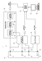
- FIG. 1 is a schematic view showing an electrical connection of the measurement system 1 according to the first embodiment of the present invention.
- This measurement system 1 is a system for measuring the electrical characteristics of cells or tissues housed in the cell retention container 10.
- the “cell” includes not only the cells cultured in the cell holding container 10 but also the cells of living tissue such as a brain slice sample housed in the cell holding container 10.
- the cell to be measured is, for example, a nerve cell such as a dopaminergic nerve cell or a serotonergic nerve cell.
- the measurement system 1 includes a cell holding container 10, four terminals 21 to 24, a voltage monitoring circuit 30 with a voltage source, a current detection circuit 40, a voltage detection circuit 50, and a current value calculation unit 60.
- the cell retention vessel 10 has four electrodes 11-14. Each of the four terminals 21 to 24 is connected to each of the electrodes 11 to 14. Specifically, the four terminals 21 to 24 include a first terminal 21, a second terminal 22, a third terminal 23, and a fourth terminal.
- FIG. 2 is a perspective view of the cell retention container 10 according to the first embodiment of the present invention.
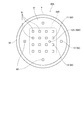
- FIG. 3 is a top view of the cell retention container 10.
- the cell retention container 10 is an embodiment of a cell retention container for accommodating and retaining cells and a medium inside and measuring the electrical characteristics of the retained cells.
- the cell retention container 10 of the present embodiment is a container for culturing cells inside and measuring the electrical characteristics of the cultured cells.
- the cell retention container 10 of the present invention is used together with the measurement system 1 to measure the extracellular voltage and the current when the voltage is applied of the cells cultured in the cell retention container 10.
- the cell holding container 10 has a main body portion 9 and an electrode portion 8.
- the main body 9 has a cup-shaped inner surface 90.
- the electrode portion 8 has a plurality of electrodes 81, 82, 83.
- the space inside the cell retention container 10 is a retention space 900 in which cells and a medium are retained. That is, the inner surface 90 forms the holding space 900.
- the sample held in the cell retention container 10 may be cells and a preservation solution, a living tissue and a medium, a living tissue and a preservation solution, and the like.
- the inner surface 90 of the main body 9 has a flat bottom surface 91 and a side surface 92.
- the side surface 92 extends upward from the edge of the bottom surface 91. Since the main body 9 of the present embodiment has a bottomed cylindrical shape, the bottom surface 91 is circular and the side surface 92 is cylindrical. However, the main body 9 may have another shape such as an ellipse or a quadrangle as long as it has a cup shape, or the bottom may be hemispherical.
- the electrode portion 8 has a plurality of array electrodes 81, a plurality of peripheral electrodes 82, and an insertion electrode 83.
- the plurality of array electrodes 81 are arranged two-dimensionally at the center of the bottom surface 91.
- the electrode portion 8 has 16 array electrodes 81 arranged in 4 columns and 4 rows.
- the array electrode 81 is a so-called carbon nanotube electrode whose surface is covered with a thin film of carbon nanotubes.
- the plurality of peripheral electrodes 82 are arranged on the peripheral edge of the bottom surface 91. That is, each of the peripheral electrodes 82 is arranged outside the plurality of array electrodes 81.
- the electrode portion 8 has four peripheral electrodes 82 arranged at equal intervals in the circumferential direction.
- the peripheral electrode 82 is a carbon nanotube electrode.
- the plurality of array electrodes 81 and the plurality of peripheral electrodes 82 are fixed to the bottom surface 91, which is a part of the inner surface 90, respectively. These electrodes 81 and 82 may be fixed to the surface of the bottom surface 91, for example, or may be fixed to the inside of the recess provided on the surface of the bottom surface 91.
- the carbon nanotube electrodes used for the array electrode 81 and the peripheral electrode 82 are formed by forming a thin carbon nanotube thin film on the surface of an electrode such as an ITO (indium tin oxide, Indium Tin Oxide) electrode or a platinum black electrode by electrolytic plating or the like. ..
- the carbon nanotube thin film has high chemical resistance and heat resistance, and is also excellent in electrical conductivity and thermal conductivity. By using a highly sensitive carbon nanotube electrode, it is possible to measure a minute electric signal in real time.
- the insertion electrode 83 is an electrode inserted into the holding space 900 of the main body 9.
- the insertion electrode 83 is a columnar electrode extending in the vertical direction. Further, in the present embodiment, the insertion electrode 83 is arranged outside the plurality of array electrodes 81.
- the insertion electrode 83 may be a plate-shaped electrode placed on the bottom surface 91, and its shape does not matter as long as it can be arranged in the holding space 900.
- the insertion electrode 83 is formed of, for example, platinum (Pt).
- one of the plurality of array electrodes 81 is used as the first working electrode 11 electrically connected to the first terminal 21.
- the insertion electrode 83 is used as the counter electrode 12 that is electrically connected to the second terminal 22.
- One of the plurality of peripheral electrodes 82 is used as the reference electrode 13 that is electrically connected to the third terminal.
- the other one of the plurality of array electrodes 81 is used as the second working electrode 14 that is electrically connected to the fourth terminal 24.
- the cells are arranged so that the first working electrode 11 and the second working electrode 14 are arranged in the cell arrangement region 910.
- the cells are sown so as to overlap the first working electrode 11 and the second working electrode 14.
- the first working electrode 11 and the second working electrode 14 may be set from among the array electrodes 81 whose upper surface is sufficiently covered with the cells.
- the tissue is arranged so as to cover both the first working electrode 11 and the second working electrode 14.
- the cells are arranged so that at least the reference electrode 13 is arranged outside the cell arrangement region 910. That is, the cells are arranged so that the cells are not arranged at least on the peripheral electrode 82.
- the voltage monitoring circuit 30 is connected to the first terminal 21, the second terminal 22, and the third terminal 23.
- the voltage monitoring circuit 30 is a circuit with a voltage source that applies a voltage between the first terminal 21 and the second terminal 22 and monitors the applied voltage between the first terminal 21 and the third terminal 23. is there. That is, the voltage monitoring circuit 30 applies a voltage between the first working electrode 11 and the counter electrode 12, and monitors the applied voltage between the first working electrode 11 and the reference electrode 13.
- the voltage monitoring circuit 30 outputs a monitoring voltage Vm which is a voltage proportional to the voltage between the first working electrode 11 and the counter electrode 12. The specific configuration of the voltage monitoring circuit 30 will be described later.
- the current detection circuit 40 is connected to the first terminal 21 and detects the current flowing through the first terminal 21. That is, the current detection circuit 40 detects the current flowing between the first working electrode 11 and the counter electrode 12.
- the current detection circuit 40 outputs a current detection voltage Vi having a voltage value proportional to the current between the first working electrode 11 and the counter electrode 12. The specific configuration of the current detection circuit 40 will be described later.
- the voltage detection circuit 50 detects the voltage between the third terminal 23 and the fourth terminal 24. That is, the voltage detection circuit 50 detects the potential difference between the second working electrode 14 and the reference electrode 13.
- the voltage detection circuit 50 outputs a detection voltage Vv which is a voltage proportional to the voltage between the second working electrode 14 and the reference electrode 13.
- a general differential amplifier circuit is used for the voltage detection circuit 50.
- the monitoring voltage Vm output by the voltage monitoring circuit 30 and the current detection voltage Vi which is the output voltage of the current detection circuit 40 are input to the current value calculation unit 60.
- the current value calculation unit 60 calculates the current value of the current flowing through the first terminal 21 based on the monitoring voltage Vm and the current detection voltage Vi.
- the current value calculation unit 60 is realized by, for example, a personal computer.
- the current value calculation unit 60 is composed of a calculation processing unit such as a CPU, a memory such as a RAM, and a storage unit such as a hard disk drive. Further, the current value calculation unit 60 is connected to a display unit 61 including a display device and the like, and an input unit 62 including a keyboard, a mouse and the like.
- FIG. 4 is a diagram showing the circuit configurations of the voltage monitoring circuit 30 and the current detection circuit 40 in the measurement system 1.
- the voltage monitoring circuit 30 includes a voltage source 31, a first operational amplifier 32, a second operational amplifier 33, and a first voltage measuring unit 34.
- the voltage source 31 is a voltage source for applying a voltage Vb between the first terminal 21 and the second terminal 22.
- the voltage source 31 has a ground terminal connected to the ground and an output terminal for outputting a voltage.
- the ground terminal of the voltage source 31 is connected to the second terminal 22. Further, the output terminal of the voltage source 31 is connected to the non-inverting input of the second operational amplifier 33.
- the first operational amplifier 32 is a general operational amplifier.
- the non-inverting input of the first operational amplifier 32 is connected to the first terminal 21.
- the inverting input of the first operational amplifier 32 is connected to the third terminal 23.
- the output of the first operational amplifier 32 is connected to the inverting input of the second operational amplifier 33.
- the second operational amplifier 33 is a general operational amplifier.
- the non-inverting input of the second operational amplifier 33 is connected to the output terminal of the voltage source 31. Further, the inverting input of the second operational amplifier 33 is connected to the output of the first operational amplifier 32.
- the output of the second operational amplifier 33 is connected to the non-inverting input of the third operational amplifier 411 described later and the inverting input of the fourth operational amplifier 421 described later.
- the first voltage measuring unit 34 measures the voltage at the connection point between the output of the first operational amplifier 32 and the inverting input of the second operational amplifier 33 as the monitoring voltage Vm.
- This monitoring voltage Vm is a voltage value close to the applied voltage Vb.
- the current detection circuit 40 is a circuit that is connected to the first terminal 21 and detects the current flowing through the first terminal 21. Specifically, the current detection circuit 40 is a circuit that outputs a voltage proportional to the current value of the current flowing through the first terminal 21.
- the current detection circuit 40 includes a current-voltage conversion circuit 41, a differential voltage amplifier circuit 42, a non-inverting amplifier circuit 43, and a second voltage measurement unit 44.
- the current-voltage conversion circuit 41 is connected to the first terminal 21 and outputs a voltage corresponding to the current flowing through the first terminal 21.
- the current-voltage conversion circuit 41 is composed of a third operational amplifier 411 and a negative feedback resistor 412.
- the non-inverting input of the third operational amplifier 411 is connected to the output of the second operational amplifier 33 and the inverting input of the fourth operational amplifier 421.
- the inverting input of the third operational amplifier 411 is connected to the first terminal 21 and the non-inverting input of the first operational amplifier 32.
- the negative feedback resistor 412 is connected to the inverting input and output of the third operational amplifier 411. That is, one end of the negative feedback resistor 412 is connected to the inverting input of the third operational amplifier 411. Further, the other end of the negative feedback resistor 412 is connected to the output of the third operational amplifier 411.
- the output of the third operational amplifier 411 that is, the output of the current-voltage conversion circuit 41 is input to the non-inverting input of the third operational amplifier 411 to a voltage proportional to the current value of the current flowing through the first terminal 21. Outputs the voltage obtained by adding the current voltage.
- the amplifier circuit including the differential voltage amplifier circuit 42 and the non-inverting amplifier circuit 43 amplifies the output voltage of the current-voltage conversion circuit 41 and outputs a voltage proportional to the current value of the current flowing through the first terminal 21.
- the differential voltage amplifier circuit 42 is composed of a fourth operational amplifier 421.
- the non-inverting input of the fourth operational amplifier 421 is connected to the output of the third operational amplifier 411.
- the inverting input of the fourth operational amplifier 421 is connected to the output of the second operational amplifier 33.
- the differential voltage amplifier circuit 42 outputs a voltage proportional to the current value of the current flowing through the first terminal 21.
- the non-inverting amplifier circuit 43 outputs a voltage proportional to the output voltage of the fourth operational amplifier 421. Therefore, the non-inverting amplifier circuit 43 outputs a voltage proportional to the current value of the current flowing through the first terminal 21.
- the non-inverting amplifier circuit 43 has a fifth arithmetic amplifier circuit 431, a first resistor 432, and a second resistor 433.
- the output of the fourth operational amplifier circuit 421 is connected to the non-inverting input of the fifth operational amplifier 431.
- One end of the first resistor 432 and one end of the second resistor 433 are connected to the inverting input of the fifth operational amplifier 431.
- One end of the first resistor 432 is connected to the non-inverting input of the fifth operational amplifier 431.
- the other end of the first resistor 432 is grounded.
- One end of the second resistor 433 is connected to the non-inverting input of the fifth operational amplifier 431.
- the other end of the second resistor 433 is connected to the output of the fifth operational amplifier 431.
- the second voltage measuring unit 44 measures the output voltage of the fifth operational amplifier 431 as the current detection voltage Vi.
- the current detection voltage Vi is a voltage value proportional to the current value of the current flowing through the first terminal.
- the potential of the first operational amplifier 11 is Vp1
- the potential of the reference electrode 13 is Vp3
- the output voltage of the first operational amplifier 32 is Va1
- the output voltage of the second operational amplifier 33 is Va2
- the third operational amplifier The output voltage of 411 is Va3
- the output voltage of the fourth operational amplifier 421 is Va4
- the output voltage of the fifth operational amplifier 431 is Va5.
- Vp1 is input to the non-inverting input and Vp3 is input to the inverting input. Therefore, assuming that the potential difference between the first working electrode 11 and the reference electrode 13 is ⁇ V, the amplification factor of the first operational amplifier 32 is A1. If, the output voltage Va1 of the first operational amplifier 32 is as follows.
- the potential difference ⁇ V between the first working electrode 11 and the reference electrode 13 can be expressed as follows.
- the potential Vp1 of the first working electrode 11 is the current value Id of the current flowing between the first working electrode 11 and the counter electrode 12, and the first working electrode 11-opposite electrode.
- the non-inverting input and the inverting input have substantially the same potential due to an imaginary short circuit.
- the output voltage Va2 of the second operational amplifier 33 is input to the non-inverting input of the third operational amplifier 411 and Vp1 is input to the inverting input, it can be expressed as follows.
- the monitoring voltage Vm and the potential difference ⁇ V between the first working electrode 11 and the reference electrode 13 are the applied voltages as shown below. Approximate to Vb.
- the output voltage Va4 of the fourth operational amplifier 421 can be expressed as follows.
- the output voltage Va4 of the fourth operational amplifier 421 is as follows.
- the output voltage Va5 of the fifth operational amplifier 431 can be expressed as follows.
- the second voltage measuring unit 44 measures the output voltage Va5 of the fifth operational amplifier 431 as the current detection voltage Vi. Therefore, the current detection voltage Vi can be expressed as follows.
- the current detection voltage Vi can be expressed as follows. Thereby, the current value Id of the current flowing through the first working electrode 11 can be calculated from the current detection voltage Vi.
- the measurement system 1 is a voltage monitoring circuit that monitors a voltage source 31 that applies a voltage between the first working electrode 11 and the counter electrode 12 and an applied voltage between the first working electrode 11 and the reference electrode. It has 30 and a current detection circuit 40 that detects a current flowing through the first working electrode 11. As a result, a voltage is applied between the first working electrode 11 and the counter electrode 12, and the voltage of the first working electrode 11-reference electrode 13 and the current flowing through the first working electrode 11 are measured. It is possible to detect the release of a neurovoltage substance in a cell.
- the voltage monitoring circuit 30 and the current detection circuit 40 have the above-mentioned circuit configuration, the voltage of the first working electrode 11-reference electrode 13 and the first working electrode are subjected to the three-electrode method.
- the current flowing through 11 can be detected.
- the voltage applied to the first working electrode 11 and the current flowing through the first working electrode can be measured by measuring the monitoring voltage by the three-electrode method. This makes it possible to more accurately detect the release of the neurovoltage substance in the cell to be measured.
- the cell retention container 10 further has a second working electrode 14.
- the measurement system 1 further includes a voltage detection circuit 60 that detects a voltage between the second working electrode 14 and the reference electrode 13. As a result, it is possible to simultaneously detect the action potential inside and outside the cell and the current due to the release of the neural voltage substance in the cell to be measured.
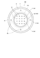
- FIG. 5 is a top view of the cell retention container 10A according to a modified example.
- the same components as those in the first embodiment are designated by the same reference numerals as those in the first embodiment.
- the insertion electrode 83A used as the counter electrode 12A may be arranged between the plurality of array electrodes 81 in the top view. As a result, the insertion electrode 83A may come into contact with the cells arranged in the cell arrangement region 910 of the cell retention container 10A.
- FIG. 6 is a top view of the cell retention container 10B according to another modified example.
- FIG. 7 is a vertical cross-sectional view of the cell retention container 10B.
- the same components as those in the first embodiment are designated by the same reference numerals as those in the first embodiment.
- the insertion electrode 83B used as the counter electrode 12B is annular.
- the insertion electrode 83B is arranged outside the plurality of array electrodes 81 and inside the plurality of peripheral electrodes 82. Further, as shown in FIG. 7, the insertion electrode 83B is placed on the bottom surface 91 of the main body 9.
- the array electrode 81 used as the first working electrode 11 and the second working electrode 14 and the peripheral electrode 82 used as the reference electrode 13 are electrodes fixed inside a recess provided on the bottom surface 91.
- the insertion electrode used as the counter electrode does not necessarily have to be cylindrical. Further, the electrode used as the counter electrode does not necessarily have to be an insertion electrode.
- the counter electrode may be an electrode fixed to the inner surface of the main body of the cell holding container.
- the configuration of the measurement system and the detailed configuration of the cell retention container may be different from each figure of the present application.
- each element appearing in the above-described embodiment or modification may be appropriately combined as long as there is no contradiction.
- Electrode 9 Main body 10, 10A, 10B Cell retention container 11 1st working electrode 12, 12A, 12B Opposite electrode 13 Reference electrode 14 2nd working electrode 21 1st terminal 22 2nd terminal 23 3rd terminal 24 4th terminal 30 Voltage monitoring circuit 31 Voltage source 32 1st arithmetic amplifier 33 2nd arithmetic amplifier 34 1st voltage measurement unit 40 Current detection circuit 41 Current voltage conversion circuit 42 Differential voltage amplification circuit 43 Non-inverting amplification circuit 44 2nd voltage Measuring unit 50 Voltage detection circuit 60 Current value calculation unit 81 Arrangement electrode 82 Peripheral electrode 83, 83A, 83B Insertion electrode 90 Inner surface 91 Bottom surface 92 Side surface 411 3rd arithmetic amplifier 412 Negative feedback resistance 421 4th arithmetic amplifier 431 5th arithmetic amplifier 432 1st resistance 433 2nd resistance 900 Retention space 910 Cell placement area
Landscapes
- Chemical & Material Sciences (AREA)
- Health & Medical Sciences (AREA)
- Life Sciences & Earth Sciences (AREA)
- Engineering & Computer Science (AREA)
- Bioinformatics & Cheminformatics (AREA)
- Biotechnology (AREA)
- General Health & Medical Sciences (AREA)
- Wood Science & Technology (AREA)
- Zoology (AREA)
- Biochemistry (AREA)
- Organic Chemistry (AREA)
- General Physics & Mathematics (AREA)
- Analytical Chemistry (AREA)
- Physics & Mathematics (AREA)
- Medicinal Chemistry (AREA)
- Genetics & Genomics (AREA)
- General Engineering & Computer Science (AREA)
- Chemical Kinetics & Catalysis (AREA)
- Electrochemistry (AREA)
- Sustainable Development (AREA)
- Microbiology (AREA)
- Biomedical Technology (AREA)
- Immunology (AREA)
- Pathology (AREA)
- Molecular Biology (AREA)
- Apparatus Associated With Microorganisms And Enzymes (AREA)
Abstract
この計測システム(1)は、細胞保持容器(10)内に保持された細胞の電気的特性を計測するための計測システムである。計測システム(1)は、細胞保持容器(10)内に配置された作用電極(11)、対向電極12および参照電極(13)とそれぞれ接続する第1端子(21)、第2端子(22)および第3端子(23)と、第1端子(21)と第2端子(22)との間に電圧を印加する電圧源と、第1端子(21)と第3端子(23)との間の印加電圧を監視する電圧監視回路(30)と、第1端子(23)を流れる電流を検出する電流検出回路(40)とを有する。これにより作用電極(11)-対向電極(12)間に電圧を印加し、作用電極(11)-参照電極(13)間の電圧と、作用電極(11)を流れる電流とを計測することにより、計測対象である細胞における神経電圧物質の放出を検出することができる。このように、従来の微小多電極アレイ法を応用して、神経細胞の神経伝達物質の計測を行うことができる。
Description
本発明は、内部で細胞を培養するとともに、培養された細胞の電気的特性を計測するための細胞保持容器と、細胞保持容器内に保持された細胞の電気的特性を計測するための計測システムと、に関する。
電気生理学の分野において、単一あるいは集団における細胞イオンチャネルの挙動を解明するイオンチャネル検出装置が知られている。イオンチャネル検出装置として、パッチクランプ法を用いた細胞内活動電位検出装置や、微小多電極アレイ(MEA,Multi Electrode Array)法を用いた細胞外活動電位検出装置が広く使用されている。通常のパッチクランプ法やMEA法といった測定法では、細胞内外の活動電位のみが計測される。従来の微小多電極アレイ(MEA)プレートは、例えば、特許文献1に記載されている。
一方、神経細胞は、酸化還元電位が印加されると、プレシナプス-ポストシナプス間において放出された神経伝達物質の酸化還元反応が促進され、当該酸化還元反応にて電荷量の変化により、電圧が印加された電極間に電流が流れる。このような神経細胞の神経伝達物質のリアルタイム計測を行うための方法の確立が求められている。
本発明は、このような事情に鑑みなされたものであり、従来の微小多電極アレイ法を応用して、神経細胞の神経伝達物質の計測を行うことができる技術を提供することを目的とする。
上記課題を解決するため、本願の第1発明は、内部に保持された細胞の電気的特性を計測するための細胞保持容器であって、前記細胞および液体が保持される保持空間を形成するカップ状の内面と、前記保持空間内の前記細胞が配置される細胞配置領域に配置され、電流検出機構と接続される作用電極と、前記保持空間内に配置され、前記作用電極との間に電圧印加機構が接続される対向電極と、前記保持空間内に配置される参照電極と、を有する。
本願の第2発明は、第1発明の細胞保持容器であって、前記内面は、平らな底面と、前記底面の縁部から延びる側面と、を有し、前記作用電極は、前記底面に間隔を開けて配列された複数の配列電極のうちの1つであり、前記参照電極は、前記複数の配列電極の外側に配置される。
本願の第3発明は、第1発明または第2発明の細胞保持容器であって、前記作用電極および前記参照電極は、前記内面に固定され、前記対向電極は、前記保持空間内に配置される。
本願の第4発明は、第2発明の細胞保持容器であって、前記対向電極は、前記保持空間内に挿入された電極である。
本願の第5発明は、細胞保持容器内に保持された細胞の電気的特性を計測するための計測システムであって、前記細胞保持容器内に配置された作用電極と接続する第1端子と、前記細胞保持容器内に配置された対向電極と接続する第2端子と、前記細胞保持容器内に配置された参照電極と接続する第3端子と、前記第1端子と前記第2端子との間に電圧を印加する電圧源と、前記第1端子と前記第3端子との間の印加電圧を監視する電圧監視回路と、前記第1端子と接続され、前記第1端子を流れる電流を検出する電流検出回路と、を有する。
本願の第6発明は、第5発明の計測システムであって、前記電圧監視回路が検出した監視電圧と、前記電流検出回路からの出力電圧とが入力される電流値演算部をさらに有し、前記電流値演算部は、前記監視電圧および前記出力電圧に基づいて、前記第1端子を流れる電流の電流値を算出する。
本願の第7発明は、第5発明または第6発明の計測システムであって、内部に細胞を保持する前記細胞保持容器をさらに有し、前記細胞保持容器は、前記細胞および液体が保持される保持空間を形成するカップ状の内面と、前記保持空間内のうちの前記細胞が配置される細胞配置領域に配置され、前記第1端子と接続する前記作用電極と、前記保持空間内に配置され、前記第2端子と接続する前記対向電極と、前記保持空間内に配置され、前記第3端子と接続する前記参照電極と、を有する。
本願の第8発明は、細胞保持容器内に保持された細胞の電気的特性を計測するための計測システムであって、前記細胞保持容器内に配置された作用電極と接続する第1端子と、前記細胞保持容器内に配置された対向電極と接続する第2端子と、前記細胞保持容器内に配置された参照電極と接続する第3端子と、を有し、前記第1端子と前記第2端子との間に電圧を印加する電圧源と、前記第1端子と前記第3端子との間の印加電圧を監視する電圧監視回路と、前記第1端子と接続され、前記第1端子を流れる電流を検出する電流検出回路と、を有し、前記電圧監視回路は、前記印加電圧と近似した電圧値となる監視電圧を計測する電圧計を有する。
本願の第9発明は、第8発明の計測システムであって、前記電圧源は、前記第2端子およびグラウンドと接続される接地端子と、電圧を出力する出力端子と、を有し、前記電圧監視回路は、非反転入力が前記第1端子と接続され、反転入力が前記第2端子と接続される、第1演算増幅器と、非反転入力が前記電圧源の前記出力端子と接続され、反転入力が前記第1演算増幅器の出力と接続される、第2演算増幅器と、をさらに有し、前記電圧計は、前記第2演算増幅器の反転入力電圧を前記監視電圧として計測する。
本願の第10発明は、第8発明または第9発明の計測システムであって、前記電流検出回路は、前記第1端子と接続され、前記第1端子を流れる前記電流に応じた電圧を出力する電流電圧変換回路を含む。
本願の第11発明は、第10発明の計測システムであって、前記電流検出回路は、前記電流電圧変換回路の出力電圧を増幅し、前記第1端子を流れる前記電流の電流値に比例する電圧を出力する増幅回路を含む。
本願の第12発明は、第9発明の計測システムであって、前記電流検出回路は、前記第1端子と接続し、前記第1端子を流れる前記電流に応じた電圧を出力する電流電圧変換回路を含み、前記電流電圧変換回路は、非反転入力が前記第2演算増幅器の出力と接続され、反転入力が前記第1端子および第1演算増幅器の非反転入力と接続される第3演算増幅器と、前記第3演算増幅器の反転入力および出力と接続される負帰還抵抗と、を有する。
本願の第13発明は、第12発明の計測システムであって、前記電流検出回路は、前記電流電圧変換回路の出力電圧を増幅し、前記第1端子を流れる前記電流の電流値に比例する電圧を出力する増幅回路を含み、前記増幅回路は、非反転入力が前記第3演算増幅器の出力と接続され、反転入力が前記第2演算増幅器の出力と接続される第4演算増幅器と、前記第4演算増幅器の出力電圧に比例する電圧を出力する非反転増幅回路と、を含む。
本願の第14発明は、内部に保持された細胞の電気的特性を計測するための細胞保持容器であって、前記細胞および液体が保持される保持空間を形成するカップ状の内面と、前記保持空間内の前記細胞が配置される細胞配置領域に配置され、電流検出機構と接続される第1作用電極および第2作用電極と、前記保持空間内に配置され、前記第1作用電極との間に電圧印加機構が接続される対向電極と、前記保持空間内に配置される参照電極と、を有する。
本願の第15発明は、第14発明の細胞保持容器であって、前記内面は、平らな底面と、 前記底面の縁部から延びる側面と、を有し、前記第1作用電極および前記第2作用電極はそれぞれ、前記底面に間隔を開けて配列された複数の電極のうちの1つであり、前記参照電極は、前記複数の電極の外側に配置される。
本願の第16発明は、細胞保持容器内に保持された細胞の電気的特性を計測するための計測システムであって、前記細胞保持容器内に配置された第1作用電極と接続する第1端子と、前記細胞保持容器内に配置された対向電極と接続する第2端子と、前記細胞保持容器内に配置された参照電極と接続する第3端子と、前記最奥培養容器内に配置された第2作用電極と接続する第4端子と、を有し、前記第1端子と前記第2端子との間に電圧を印加する電圧源と、前記第1端子と前記第3端子との間の印加電圧を監視する電圧監視回路と、前記第1端子と接続され、前記第1端子を流れる電流を検出する電流検出回路と、前記第3端子と前記第4端子との間の電圧を検出する電圧検出回路と、を有する。
本願の第17発明は、第16発明の計測システムであって、前記電圧監視回路が検出した監視電圧と、前記電流検出回路からの出力電圧とが入力される制御部をさらに有し、前記制御部は、前記監視電圧および前記出力電圧に基づいて、前記第1端子を流れる電流の電流値を算出する。
本願の第18発明は、第16発明または第17発明の計測システムであって、内部に細胞を保持する前記細胞保持容器をさらに有し、前記細胞保持容器は、前記細胞および液体が保持される保持空間を形成するカップ状の内面と、前記保持空間内のうちの前記細胞が配置される細胞配置領域に配置され、前記第1端子と接続する前記第1作用電極と、前記保持空間内に配置され、前記第2端子と接続する前記対向電極と、前記保持空間内に配置され、前記第3端子と接続する前記参照電極と、前記細胞配置領域に配置され、前記第4端子と接続する前記第2作用電極と、を有する。
本願の第1発明~第7発明によれば、作用電極-対向電極間に電圧を印加し、作用電極-参照電極間の電圧と、作用電極を流れる電流とを計測することにより、計測対象である細胞における神経電圧物質の放出を検出することができる。
本願の第8発明~第13発明によれば、三電極法により、監視電圧と、電流とを検出することができる。電圧を直接印加する作用電極-対向電極間の電圧を直接計測する二電極法では、通電による電圧降下が大きく、実際の電位がわからない。このため、三電極法により監視電圧を計測することにより、作用電極にかかる電圧と、作用電極を流れる電流とを計測することができる。これにより、計測対象である細胞における神経電圧物質の放出をより正確に検出することができる。
本願の第14発明~第18発明によれば、計測対象である細胞について、細胞内外の活動電位と、神経電圧物質の放出による電流とを、同時に検出することができる。
以下、本発明の実施形態について、図面を参照しつつ説明する。なお、以下の説明において細胞保持容器の底面に平行な方向を「水平方向」、水平方向に直交する方向を「上下方向」と称する。しかしながら、細胞保持容器の使用時の姿勢は、細胞保持容器の底面が必ずしも水平方向とならなくてもよい。
<1.第1実施形態>
図1は、本発明の第1実施形態に係る計測システム1の電気的な接続を示した概略図である。この計測システム1は、細胞保持容器10内に収容された細胞または組織の電気的特性を計測するためのシステムである。ここで、「細胞」とは、細胞保持容器10内で培養された細胞だけでなく、細胞保持容器10内に収容された、脳スライス試料等の生体組織の細胞も含まれる。計測システム1において、計測対象となる細胞は、例えば、ドーパミン作動性神経細胞や、セロトニン作動性神経細胞等の神経細胞である。
図1は、本発明の第1実施形態に係る計測システム1の電気的な接続を示した概略図である。この計測システム1は、細胞保持容器10内に収容された細胞または組織の電気的特性を計測するためのシステムである。ここで、「細胞」とは、細胞保持容器10内で培養された細胞だけでなく、細胞保持容器10内に収容された、脳スライス試料等の生体組織の細胞も含まれる。計測システム1において、計測対象となる細胞は、例えば、ドーパミン作動性神経細胞や、セロトニン作動性神経細胞等の神経細胞である。
計測システム1は、細胞保持容器10と、4つの端子21~24と、電圧源付き電圧監視回路30と、電流検出回路40と、電圧検出回路50と、電流値演算部60とを有する。細胞保持容器10は、4つの電極11~14を有する。4つの端子21~24はそれぞれ、電極11~14のそれぞれと接続される。4つの端子21~24は、具体的には、第1端子21、第2端子22、第3端子23および第4端子を含む。
図2は、本発明の第1実施形態に係る細胞保持容器10の斜視図である。図3は、細胞保持容器10の上面図である。
細胞保持容器10は、内部に細胞および培地を収容および保持するとともに、保持された細胞の電気的特性を計測するための細胞保持容器の一実施形態である。本実施形態の細胞保持容器10は、内部で細胞を培養するとともに、培養された細胞の電気的特性を計測するための容器である。具体的には、本発明の細胞保持容器10は、計測システム1とともに用いられ、細胞保持容器10内で培養された細胞の細胞外電圧と電圧印加時電流とが計測される。
図2に示すように、細胞保持容器10は、本体部9と、電極部8とを有する。本体部9は、カップ状の内面90を有する。電極部8は、複数の電極81,82,83を有する。細胞保持容器10の内部の空間は、細胞および培地が保持される保持空間900である。すなわち、内面90が、保持空間900を形成する。なお、細胞保持容器10内に保持される試料は、細胞および保存液、生体組織および培地、生体組織および保存液等であってもよい。
本体部9の内面90は、平らな底面91と、側面92を有する。側面92は、底面91の縁部から上方に延びる。本実施形態の本体部9は有底円筒状であるため、底面91は円形であり、側面92は円筒状である。しかしながら、本体部9は、カップ状であれば、底面が楕円形、四角形等の他の形状であってもよいし、底部が半球状であってもよい。
細胞の培養時には、底面91の中央を中心として、細胞が播かれる。これにより、底面91の中央は、細胞が配置される細胞配置領域910に含まれる。図2中には、細胞配置領域910の一例が破線で示されている。
図2および図3に示すように、電極部8は、複数の配列電極81と、複数の周縁電極82と、挿入電極83とを有する。
複数の配列電極81は、底面91の中央において、2次元的に配列される。本実施形態では、電極部8は縦4列、横4列に配列された16個の配列電極81を有する。また、配列電極81は、表面がカーボンナノチューブの薄膜により覆われた、いわゆるカーボンナノチューブ電極である。
複数の周縁電極82は、底面91の周縁部に配置される。すなわち、周縁電極82はそれぞれ、複数の配列電極81の外側に配置される。本実施形態では、電極部8は、周方向に等間隔に配置された4個の周縁電極82を有する。また、周縁電極82は、カーボンナノチューブ電極である。
複数の配列電極81および複数の周縁電極82はそれぞれ、内面90の一部である底面91に固定される。これらの電極81,82は、例えば、底面91の表面に固定されてもよいし、底面91の表面に設けられた凹部の内部に固定されてもよい。
配列電極81および周縁電極82に用いられるカーボンナノチューブの電極は、ITO(酸化インジウムスズ、Indium Tin Oxide)電極または白金黒電極等の電極の表面に電解めっき等によりカーボンナノチューブ薄膜を形成したものである。カーボンナノチューブ薄膜は、薬品耐性および熱耐性が高く、かつ、電気伝導性および熱伝導性にも優れている。高感度なカーボンナノチューブ電極を用いることにより、微小な電気信号をリアルタイムに計測することが可能となる。
挿入電極83は、本体部9の保持空間900に挿入された電極である。本実施形態では、挿入電極83は、鉛直方向に延びる円柱状の電極である。また、本実施形態では、挿入電極83は、複数の配列電極81よりも外側に配置される。なお、挿入電極83は、底面91上に載置される板状の電極であってもよいし、保持空間900内に配置できれば、その形状は問わない。挿入電極83は、例えば、白金(Pt)により形成される。
図1および図3に示すように、複数の配列電極81のうちの1つが、第1端子21と電気的に接続される第1作用電極11として用いられる。挿入電極83が、第2端子22と電気的に接続される対向電極12として用いられる。複数の周縁電極82のうちの1つが、第3端子と電気的に接続される参照電極13として用いられる。また、複数の配列電極81のうちの他の1つが、第4端子24と電気的に接続される第2作用電極14として用いられる。
ここで、細胞を細胞保持容器10内に配置する際には、第1作用電極11および第2作用電極14が細胞配置領域910内に配置されるように、細胞を配置する。具体的には、細胞保持容器10内で細胞を培養する場合には、第1作用電極11および第2作用電極14の上に重なるように細胞を播く。なお、細胞の培養後に、配列電極81の中で、その上面を細胞が十分に覆っているものの中から、第1作用電極11および第2作用電極14を設定してもよい。また、計測対象が組織である場合には、第1作用電極11および第2作用電極14の双方を覆うように、当該組織を配置する。
一方、細胞を細胞保持容器10内に配置する際に、少なくとも参照電極13が細胞配置領域910外に配置されるように、細胞を配置する。すなわち、少なくとも周縁電極82上に細胞が配置されないように、細胞を配置する。
図1に示すように、電圧監視回路30は、第1端子21、第2端子22および第3端子23と接続される。電圧監視回路30は、第1端子21と第2端子22との間に電圧を印加するとともに、第1端子21と第3端子23との間の印加電圧を監視する、電圧源付きの回路である。すなわち、電圧監視回路30は、第1作用電極11と対向電極12との間に電圧を印加するとともに、第1作用電極11と参照電極13との間の印加電圧を監視する。電圧監視回路30は、第1作用電極11-対向電極12間の電圧に比例した電圧である監視電圧Vmを出力する。電圧監視回路30の具体的な構成については、後述する。
電流検出回路40は、第1端子21と接続され、第1端子21を流れる電流を検出する。すなわち、電流検出回路40は、第1作用電極11と対向電極12との間に流れる電流を検出する。電流検出回路40は、第1作用電極11-対向電極12間の電流に比例した電圧値を有する電流検出電圧Viを出力する。電流検出回路40の具体的な構成については、後述する。
電圧検出回路50は、第3端子23と第4端子24との間の電圧を検出する。すなわち、電圧検出回路50は、第2作用電極14と参照電極13との間の電位差を検出する。電圧検出回路50は、第2作用電極14-参照電極13間の電圧に比例した電圧である検出電圧Vvを出力する。電圧検出回路50には、例えば、一般的な差動増幅回路が用いられる。
電流値演算部60には、電圧監視回路30が出力した監視電圧Vmと、電流検出回路40の出力電圧である電流検出電圧Viとが入力される。電流値演算部60は、監視電圧Vmおよび電流検出電圧Viに基づいて、第1端子21を流れる電流の電流値を算出する。
電流値演算部60は、例えば、パーソナルコンピュータにより実現される。電流値演算部60は、CPU等の演算処理部、RAM等のメモリ、およびハードディスクドライブ等の記憶部から構成される。また、電流値演算部60は、ディスプレイ装置等からなる表示部61と、キーボードやマウス等からなる入力部62と接続されている。
続いて、電圧監視回路30および電流検出回路40の具体的な構成について、図4を参照しつつ説明する。図4は、計測システム1のうち、電圧監視回路30および電流検出回路40の回路構成を示した図である。
図4に示すように、電圧監視回路30は、電圧源31と、第1演算増幅器32と、第2演算増幅器33と、第1電圧計測部34を有する。
電圧源31は、第1端子21と第2端子22との間に電圧Vbを印加するための電圧源である。電圧源31は、グラウンドと接続される接地端子と、電圧を出力する出力端子とを有する。電圧源31の接地端子は、第2端子22と接続される。また、電圧源31の出力端子は、第2演算増幅器33の非反転入力と接続される。
第1演算増幅器32は、一般的なオペアンプである。第1演算増幅器32の非反転入力は、第1端子21と接続される。第1演算増幅器32の反転入力は、第3端子23と接続される。第1演算増幅器32の出力は、第2演算増幅器33の反転入力と接続される。
第2演算増幅器33は、一般的なオペアンプである。第2演算増幅器33の非反転入力は、電圧源31の出力端子と接続される。また、第2演算増幅器33の反転入力は、第1演算増幅器32の出力と接続される。第2演算増幅器33の出力は、後述する第3演算増幅器411の非反転入力と、後述する第4演算増幅器421の反転入力と接続される。
第1電圧計測部34は、第1演算増幅器32の出力と第2演算増幅器33の反転入力との接続箇所の電圧を、監視電圧Vmとして計測する。この監視電圧Vmは、印加電圧Vbと近似した電圧値となる。
電流検出回路40は、第1端子21と接続され、第1端子21を流れる電流を検出するための回路である。具体的には、電流検出回路40は、第1端子21を流れる電流の電流値に比例する電圧を出力する回路である。電流検出回路40は、電流電圧変換回路41と、差動電圧増幅回路42と、非反転増幅回路43と、第2電圧計測部44とを有する。
電流電圧変換回路41は、第1端子21と接続され、第1端子21を流れる電流に応じた電圧を出力する。電流電圧変換回路41は、第3演算増幅器411と、負帰還抵抗412とにより構成される。
第3演算増幅器411の非反転入力は、第2演算増幅器33の出力および第4演算増幅器421の反転入力と接続される。第3演算増幅器411の反転入力は、第1端子21と、第1演算増幅器32の非反転入力と接続される。
負帰還抵抗412は、第3演算増幅器411の反転入力および出力と接続される。すなわち、負帰還抵抗412の一方側の端部は、第3演算増幅器411の反転入力と接続される。また、負帰還抵抗412の他方側の端部は、第3演算増幅器411の出力と接続される。これにより、第3演算増幅器411の出力、すなわち、電流電圧変換回路41の出力は、第1端子21を流れる電流の電流値に比例する電圧に、第3演算増幅器411の非反転入力に入力される電圧を加算した電圧を出力する。
差動電圧増幅回路42および非反転増幅回路43からなる増幅回路は、電流電圧変換回路41の出力電圧を増幅するとともに、第1端子21を流れる電流の電流値に比例する電圧を出力する。
差動電圧増幅回路42は、第4演算増幅器421により構成される。第4演算増幅器421の非反転入力は、第3演算増幅器411の出力と接続される。第4演算増幅器421の反転入力は、第2演算増幅器33の出力と接続される。これにより、差動電圧増幅回路42は、第1端子21を流れる電流の電流値に比例する電圧を出力する。
非反転増幅回路43は、第4演算増幅器421の出力電圧に比例する電圧を出力する。このため、非反転増幅回路43は、第1端子21を流れる電流の電流値に比例する電圧を出力する。
非反転増幅回路43は、第5演算増幅回路431と、第1抵抗432と、第2抵抗433とを有する。第5演算増幅器431の非反転入力には、第4演算増幅回路421の出力が接続される。第5演算増幅器431の反転入力には、第1抵抗432の一端および第2抵抗433の一端が接続される。
第1抵抗432の一端は、第5演算増幅器431の非反転入力と接続される。また、第1抵抗432の他端は、接地される。第2抵抗433の一端は、第5演算増幅器431の非反転入力と接続される。また、第2抵抗433の他端は、第5演算増幅器431の出力と接続される。
第2電圧計測部44は、第5演算増幅器431の出力電圧を、電流検出電圧Viとして計測する。この電流検出電圧Viは、第1端子を流れる電流の電流値と比例した電圧値となる。
上記の回路構成において、第1作用電極11の電位をVp1、参照電極13の電位をVp3、第1演算増幅器32の出力電圧をVa1、第2演算増幅器33の出力電圧をVa2、第3演算増幅器411の出力電圧をVa3、第4演算増幅器421の出力電圧をVa4、第5演算増幅器431の出力電圧をVa5とする。
電圧源31によって第1端子21-第2端子22間に電圧を印加すると、第1作用電極11-対向電極12間を保持空間900内の細胞および液体を介して電流が流れる。これにより、第1作用電極11および対向電極12の表面において電気化学反応が生じる。一方、参照電極13には、電流は殆ど流れない。
第1演算増幅器32において、非反転入力にVp1、反転入力にVp3が入力されるため、第1作用電極11-参照電極13間の電位差をΔVとすると、第1演算増幅器32の増幅率がA1である場合、第1演算増幅器32の出力電圧Va1は以下の通りである。

ここで、第1電圧計測部34の計測する監視電圧Vmは、第1演算増幅器32の出力電圧Va1と等しい。したがって、第1演算増幅器32の増幅率A1=1とすると、監視電圧Vmは以下の通りである。これにより、監視電圧Vmを計測することによって、第1作用電極11-参照電極13間の電位差ΔVを計測することができる。

次に、第2演算増幅器33の非反転入力にVb、反転入力にΔVが入力されるため、第2演算増幅器33の出力電圧Va2は、第2演算増幅器33の増幅率A2を用いて以下のように表せる。

したがって、第1作用電極11-参照電極13間の電位差ΔVは、以下のように表せる。

ここで、第2端子22は接地されているため、第1作用電極11の電位Vp1は、第1作用電極11-対向電極12間を流れる電流の電流値Id、第1作用電極11-対向電極12間の細胞および液体のインピーダンスZを用いて以下のように表せる。

第3演算増幅器411は負帰還抵抗412が接続されているため、イマジナリーショートにより非反転入力と反転入力はほぼ同電位となる。ここで、第3演算増幅器411の非反転入力に第2演算増幅器33の出力電圧Va2、反転入力にVp1が入力されるため、以下のように表せる。

式(4)~(6)より、以下の式が成り立つ。

このため、第3演算増幅器411の増幅率A2が十分に大きい(例えばA2=100)場合、以下のように、監視電圧Vmおよび第1作用電極11-参照電極13間の電位差ΔVは、印加電圧Vbと近似する。

一方、電流電圧変換回路41の構成より、負帰還抵抗412の抵抗値をRrとすると、第1作用電極11および第1端子21に流れる電流はIdであることから、第3演算増幅器411の出力電圧Va3は以下のように表せる。

続いて、第4演算増幅器421の増幅率が1であることから、第4演算増幅器421の出力電圧Va4は以下のように表せる。

式(9)および式(10)より、第4演算増幅器421の出力電圧Va4は以下のようになる。

非反転増幅回路43において、第1抵抗432の抵抗値をR1、第2抵抗433の抵抗値をR2とすると、第5演算増幅器431の出力電圧Va5は、以下のように表せる。

第2電圧計測部44は、第5演算増幅器431の出力電圧Va5を電流検出電圧Viとして計測する。このため、電流検出電圧Viは、以下のように表せる。

したがって、式(11)および式(13)より、電流検出電圧Viは、以下のように表せる。これにより、第1作用電極11を流れる電流の電流値Idを、電流検出電圧Viから算出することができる。

上述の通り、この計測システム1では、第1作用電極11、対向電極12および参照電極13を有する細胞保持容器10を用いて、細胞の電気的特性を計測する。また、この計測システム1は、第1作用電極11と対向電極12との間に電圧を印加する電圧源31と、第1作用電極11と参照電極との間の印加電圧を監視する電圧監視回路30と、第1作用電極11を流れる電流を検出する電流検出回路40とを有する。これにより、第1作用電極11-対向電極12間に電圧を印加し、第1作用電極11-参照電極13の電圧と、第1作用電極11を流れる電流とを計測することにより、計測対象である細胞における神経電圧物質の放出を検出することができる。
また、この計測システム1では、電圧監視回路30と電流検出回路40とが上述の回路構成を有することにより、三電極法により、第1作用電極11-参照電極13の電圧と、第1作用電極11を流れる電流とを検出することができる。電圧を直接印加する第1作用電極11-対向電極12間の電圧を直接計測する二電極法では、通電による電圧降下が大きく、実際の電位を計測することができない。これに対し、この計測システム1では、三電極法により監視電圧を計測することにより、第1作用電極11にかかる電圧と、第1作用電極を流れる電流とを計測することができる。これにより、計測対象である細胞における神経電圧物質の放出をより正確に検出することができる。
また、この計測システム1では、細胞保持容器10がさらに第2作用電極14を有する。そして、この計測システム1は、第2作用電極14と参照電極13との間の電圧を検出する電圧検出回路60をさらに有する。これにより、計測対象である細胞について、細胞内外の活動電位と、神経電圧物質の放出による電流とを、同時に検出することができる。
このように、この計測システム1を用いることにより、従来の微小多電極アレイ法を応用して、神経細胞の神経伝達物質の計測を行うことができる。
<2.変形例>
以上、本発明の一実施形態について説明したが、本発明は、上記の実施形態に限定されるものではない。
以上、本発明の一実施形態について説明したが、本発明は、上記の実施形態に限定されるものではない。
図5は、一変形例に係る細胞保持容器10Aの上面図である。図5中において、第1実施形態と同様の構成については、第1実施形態と同じ符号が付されている。図5に示すように、対向電極12Aとして用いられる挿入電極83Aが、上面視において複数の配列電極81の間に配置されてもよい。これにより、挿入電極83Aが、細胞保持容器10Aの細胞配置領域910に配置された細胞と接触してもよい。
図6は、他の変形例に係る細胞保持容器10Bの上面図である。図7は、細胞保持容器10Bの縦断面図である。図6および図7中において、第1実施形態と同様の構成については、第1実施形態と同じ符号が付されている。図6および図7の例では、対向電極12Bとして用いられる挿入電極83Bは、円環状である。挿入電極83Bは、複数の配列電極81の外側、かつ、複数の周縁電極82の内側に配置される。また、図7に示すように、挿入電極83Bは、本体部9の底面91の上に載置される。一方、第1作用電極11および第2作用電極14として用いられる配列電極81と、参照電極13として用いられる周縁電極82とは、底面91に設けられた凹部の内部に固定される電極である。
図6および図7の例のように、対向電極として用いられる挿入電極は、必ずしも円柱状でなくてもよい。また、対向電極として用いられる電極は、必ずしも挿入電極でなくてもよい。対向電極は、細胞保持容器の本体部の内面に固定された電極であってもよい。
また、計測システムの構成や、細胞保持容器の細部の構成については、本願の各図と相違していてもよい。また、上記の実施形態や変形例に登場した各要素を、矛盾が生じない範囲で、適宜に組み合わせてもよい。
1 計測システム
8 電極部
9 本体部
10,10A,10B 細胞保持容器
11 第1作用電極
12,12A,12B 対向電極
13 参照電極
14 第2作用電極
21 第1端子
22 第2端子
23 第3端子
24 第4端子
30 電圧監視回路
31 電圧源
32 第1演算増幅器
33 第2演算増幅器
34 第1電圧計測部
40 電流検出回路
41 電流電圧変換回路
42 差動電圧増幅回路
43 非反転増幅回路
44 第2電圧計測部
50 電圧検出回路
60 電流値演算部
81 配列電極
82 周縁電極
83,83A,83B 挿入電極
90 内面
91 底面
92 側面
411 第3演算増幅器
412 負帰還抵抗
421 第4演算増幅器
431 第5演算増幅器
432 第1抵抗
433 第2抵抗
900 保持空間
910 細胞配置領域
8 電極部
9 本体部
10,10A,10B 細胞保持容器
11 第1作用電極
12,12A,12B 対向電極
13 参照電極
14 第2作用電極
21 第1端子
22 第2端子
23 第3端子
24 第4端子
30 電圧監視回路
31 電圧源
32 第1演算増幅器
33 第2演算増幅器
34 第1電圧計測部
40 電流検出回路
41 電流電圧変換回路
42 差動電圧増幅回路
43 非反転増幅回路
44 第2電圧計測部
50 電圧検出回路
60 電流値演算部
81 配列電極
82 周縁電極
83,83A,83B 挿入電極
90 内面
91 底面
92 側面
411 第3演算増幅器
412 負帰還抵抗
421 第4演算増幅器
431 第5演算増幅器
432 第1抵抗
433 第2抵抗
900 保持空間
910 細胞配置領域
Claims (18)
- 内部に保持された細胞の電気的特性を計測するための細胞保持容器であって、
前記細胞および液体が保持される保持空間を形成するカップ状の内面と、
前記保持空間内の前記細胞が配置される細胞配置領域に配置され、電流検出機構と接続される作用電極と、
前記保持空間内に配置され、前記作用電極との間に電圧印加機構が接続される対向電極と、
前記保持空間内に配置される参照電極と、
を有する、細胞保持容器。 - 請求項1に記載の細胞保持容器であって、
前記内面は、
平らな底面と、
前記底面の縁部から延びる側面と、
を有し、
前記作用電極は、前記底面に間隔を開けて配列された複数の配列電極のうちの1つであり、
前記参照電極は、前記複数の配列電極の外側に配置される、細胞保持容器。 - 請求項1または請求項2に記載の細胞保持容器であって、
前記作用電極および前記参照電極は、前記内面に固定され、
前記対向電極は、前記保持空間内に配置される、細胞保持容器。 - 請求項2に記載の細胞保持容器であって、
前記対向電極は、前記保持空間内に挿入された電極である、細胞保持容器。 - 細胞保持容器内に保持された細胞の電気的特性を計測するための計測システムであって、
前記細胞保持容器内に配置された作用電極と接続する第1端子と、
前記細胞保持容器内に配置された対向電極と接続する第2端子と、
前記細胞保持容器内に配置された参照電極と接続する第3端子と、
前記第1端子と前記第2端子との間に電圧を印加する電圧源と、
前記第1端子と前記第3端子との間の印加電圧を監視する電圧監視回路と、
前記第1端子と接続され、前記第1端子を流れる電流を検出する電流検出回路と、
を有する、計測システム。 - 請求項5に記載の計測システムであって、
前記電圧監視回路が検出した監視電圧と、前記電流検出回路からの出力電圧とが入力される電流値演算部
をさらに有し、
前記電流値演算部は、前記監視電圧および前記出力電圧に基づいて、前記第1端子を流れる電流の電流値を算出する、計測システム。 - 請求項5または請求項6に記載の計測システムであって、
内部に細胞を保持する前記細胞保持容器
をさらに有し、
前記細胞保持容器は、
前記細胞および液体が保持される保持空間を形成するカップ状の内面と、
前記保持空間内のうちの前記細胞が配置される細胞配置領域に配置され、前記第1端子と接続する前記作用電極と、
前記保持空間内に配置され、前記第2端子と接続する前記対向電極と、
前記保持空間内に配置され、前記第3端子と接続する前記参照電極と、
を有する、計測システム。 - 細胞保持容器内に保持された細胞の電気的特性を計測するための計測システムであって、
前記細胞保持容器内に配置された作用電極と接続する第1端子と、
前記細胞保持容器内に配置された対向電極と接続する第2端子と、
前記細胞保持容器内に配置された参照電極と接続する第3端子と、
を有し、
前記第1端子と前記第2端子との間に電圧を印加する電圧源と、
前記第1端子と前記第3端子との間の印加電圧を監視する電圧監視回路と、
前記第1端子と接続され、前記第1端子を流れる電流を検出する電流検出回路と、
を有し、
前記電圧監視回路は、前記第1端子と前記第3端子との間の印加電圧と近似した電圧値となる監視電圧を計測する電圧計を有する、計測システム。 - 請求項8に記載の計測システムであって、
前記電圧源は、
前記第2端子およびグラウンドと接続される接地端子と、
電圧を出力する出力端子と、
を有し、
前記電圧監視回路は、
非反転入力が前記第1端子と接続され、反転入力が前記第2端子と接続される、第1演算増幅器と、
非反転入力が前記電圧源の前記出力端子と接続され、反転入力が前記第1演算増幅器の出力と接続される、第2演算増幅器と、
をさらに有し、
前記電圧計は、前記第2演算増幅器の反転入力電圧を前記監視電圧として計測する、計測システム。 - 請求項8または請求項9に記載の計測システムであって、
前記電流検出回路は、
前記第1端子と接続され、前記第1端子を流れる前記電流に応じた電圧を出力する電流電圧変換回路
を含む、計測システム。 - 請求項10に記載の計測システムであって、
前記電流検出回路は、
前記電流電圧変換回路の出力電圧を増幅し、前記第1端子を流れる前記電流の電流値に比例する電圧を出力する増幅回路
を含む、計測システム。 - 請求項9に記載の計測システムであって、
前記電流検出回路は、
前記第1端子と接続し、前記第1端子を流れる前記電流に応じた電圧を出力する電流電圧変換回路
を含み、
前記電流電圧変換回路は、
非反転入力が前記第2演算増幅器の出力と接続され、反転入力が前記第1端子および第1演算増幅器の非反転入力と接続される第3演算増幅器と、
前記第3演算増幅器の反転入力および出力と接続される負帰還抵抗と、
を有する、計測システム。 - 請求項12に記載の計測システムであって、
前記電流検出回路は、
前記電流電圧変換回路の出力電圧を増幅し、前記第1端子を流れる前記電流の電流値に比例する電圧を出力する増幅回路
を含み、
前記増幅回路は、
非反転入力が前記第3演算増幅器の出力と接続され、反転入力が前記第2演算増幅器の出力と接続される第4演算増幅器と、
前記第4演算増幅器の出力電圧に比例する電圧を出力する非反転増幅回路と、
を含む、計測システム。 - 内部に保持された細胞の電気的特性を計測するための細胞保持容器であって、
前記細胞および液体が保持される保持空間を形成するカップ状の内面と、
前記保持空間内の前記細胞が配置される細胞配置領域に配置され、電流検出機構と接続される第1作用電極および第2作用電極と、
前記保持空間内に配置され、前記第1作用電極との間に電圧印加機構が接続される対向電極と、
前記保持空間内に配置される参照電極と、
を有する、細胞保持容器。 - 請求項14に記載の細胞保持容器であって、
前記内面は、
平らな底面と、
前記底面の縁部から延びる側面と、
を有し、
前記第1作用電極および前記第2作用電極はそれぞれ、前記底面に間隔を開けて配列された複数の電極のうちの1つであり、
前記参照電極は、前記複数の電極の外側に配置される、細胞保持容器。 - 細胞保持容器内に保持された細胞の電気的特性を計測するための計測システムであって、
前記細胞保持容器内に配置された第1作用電極と接続する第1端子と、
前記細胞保持容器内に配置された対向電極と接続する第2端子と、
前記細胞保持容器内に配置された参照電極と接続する第3端子と、
前記最奥培養容器内に配置された第2作用電極と接続する第4端子と、
を有し、
前記第1端子と前記第2端子との間に電圧を印加する電圧源と、
前記第1端子と前記第3端子との間の印加電圧を監視する電圧監視回路と、
前記第1端子と接続され、前記第1端子を流れる電流を検出する電流検出回路と、
前記第3端子と前記第4端子との間の電圧を検出する電圧検出回路と、
を有する、計測システム。 - 請求項16に記載の計測システムであって、
前記電圧監視回路が検出した監視電圧と、前記電流検出回路からの出力電圧とが入力される制御部
をさらに有し、
前記制御部は、前記監視電圧および前記出力電圧に基づいて、前記第1端子を流れる電流の電流値を算出する、計測システム。 - 請求項16または請求項17に記載の計測システムであって、
内部に細胞を保持する前記細胞保持容器
をさらに有し、
前記細胞保持容器は、
前記細胞および液体が保持される保持空間を形成するカップ状の内面と、
前記保持空間内のうちの前記細胞が配置される細胞配置領域に配置され、前記第1端子と接続する前記第1作用電極と、
前記保持空間内に配置され、前記第2端子と接続する前記対向電極と、
前記保持空間内に配置され、前記第3端子と接続する前記参照電極と、
前記細胞配置領域に配置され、前記第4端子と接続する前記第2作用電極と、
を有する、計測システム。
Applications Claiming Priority (6)
| Application Number | Priority Date | Filing Date | Title |
|---|---|---|---|
| JP2019-052715 | 2019-03-20 | ||
| JP2019052715A JP2020150853A (ja) | 2019-03-20 | 2019-03-20 | 計測システム |
| JP2019-052716 | 2019-03-20 | ||
| JP2019-052714 | 2019-03-20 | ||
| JP2019052714A JP2020150852A (ja) | 2019-03-20 | 2019-03-20 | 細胞保持容器および計測システム |
| JP2019052716A JP2020150854A (ja) | 2019-03-20 | 2019-03-20 | 細胞保持容器および計測システム |
Publications (1)
| Publication Number | Publication Date |
|---|---|
| WO2020189172A1 true WO2020189172A1 (ja) | 2020-09-24 |
Family
ID=72520261
Family Applications (1)
| Application Number | Title | Priority Date | Filing Date |
|---|---|---|---|
| PCT/JP2020/006899 Ceased WO2020189172A1 (ja) | 2019-03-20 | 2020-02-20 | 細胞保持容器および計測システム |
Country Status (1)
| Country | Link |
|---|---|
| WO (1) | WO2020189172A1 (ja) |
Cited By (4)
| Publication number | Priority date | Publication date | Assignee | Title |
|---|---|---|---|---|
| WO2023204018A1 (ja) * | 2022-04-22 | 2023-10-26 | 株式会社Screenホールディングス | インピーダンス計測装置およびインピーダンス計測方法 |
| WO2023204019A1 (ja) * | 2022-04-22 | 2023-10-26 | 株式会社Screenホールディングス | インピーダンス計測装置およびインピーダンス計測方法 |
| WO2025158477A1 (ja) * | 2024-01-22 | 2025-07-31 | 日置電機株式会社 | 非反転増幅回路 |
| WO2025182853A1 (ja) * | 2024-02-29 | 2025-09-04 | 一般財団法人生産技術研究奨励会 | 細胞組織の電気シグナルを計測する方法及び増感剤 |
Citations (1)
| Publication number | Priority date | Publication date | Assignee | Title |
|---|---|---|---|---|
| JP2003513275A (ja) * | 1999-11-04 | 2003-04-08 | アドバンスド センサー テクノロジーズ, インコーポレイテッド | 統合された制御および解析回路を備えた微視的なマルチサイトセンサアレイ |
-
2020
- 2020-02-20 WO PCT/JP2020/006899 patent/WO2020189172A1/ja not_active Ceased
Patent Citations (1)
| Publication number | Priority date | Publication date | Assignee | Title |
|---|---|---|---|---|
| JP2003513275A (ja) * | 1999-11-04 | 2003-04-08 | アドバンスド センサー テクノロジーズ, インコーポレイテッド | 統合された制御および解析回路を備えた微視的なマルチサイトセンサアレイ |
Non-Patent Citations (2)
| Title |
|---|
| SONG , Y. ET AL.: "A novel dual mode microelectrode array for neuroelectrical and neurochemical recording in vitro", BIOSENSORS AND BIOELECTRONICS, vol. 38, 17 May 2012 (2012-05-17), pages 416 - 420, XP028398380, DOI: 10.1016/j.bios.2012.05.011 * |
| XU, H. ET AL.: "Selective Recognition of 5-Hydroxytryptamine and Dopamine on a Multi-Walled Carbon Nanotube-Chitosan Hybrid Film-Modified Microelectrode Array", SENSORS, vol. 15, 8 January 2015 (2015-01-08), pages 1008 - 1021, XP055740892 * |
Cited By (8)
| Publication number | Priority date | Publication date | Assignee | Title |
|---|---|---|---|---|
| WO2023204018A1 (ja) * | 2022-04-22 | 2023-10-26 | 株式会社Screenホールディングス | インピーダンス計測装置およびインピーダンス計測方法 |
| WO2023204019A1 (ja) * | 2022-04-22 | 2023-10-26 | 株式会社Screenホールディングス | インピーダンス計測装置およびインピーダンス計測方法 |
| JP2023160374A (ja) * | 2022-04-22 | 2023-11-02 | 株式会社Screenホールディングス | インピーダンス計測装置およびインピーダンス計測方法 |
| EP4513180A4 (en) * | 2022-04-22 | 2026-03-25 | Screen Holdings Co Ltd | IMPEDANCE MEASUREMENT DEVICE AND METHOD |
| JP7853825B2 (ja) | 2022-04-22 | 2026-04-30 | 株式会社Screenホールディングス | インピーダンス計測装置およびインピーダンス計測方法 |
| WO2025158477A1 (ja) * | 2024-01-22 | 2025-07-31 | 日置電機株式会社 | 非反転増幅回路 |
| WO2025182853A1 (ja) * | 2024-02-29 | 2025-09-04 | 一般財団法人生産技術研究奨励会 | 細胞組織の電気シグナルを計測する方法及び増感剤 |
| JP7755910B1 (ja) * | 2024-02-29 | 2025-10-17 | 一般財団法人生産技術研究奨励会 | 細胞組織の電気シグナルを計測する方法及び増感剤 |
Similar Documents
| Publication | Publication Date | Title |
|---|---|---|
| Liu et al. | Recent trends in carbon-based microelectrodes as electrochemical sensors for neurotransmitter detection: A review | |
| Al-Graiti et al. | Hybrid graphene/conducting polymer strip sensors for sensitive and selective electrochemical detection of serotonin | |
| EP3926339B1 (en) | Electrochemical sensor having symmetrically distributed analyte sensitive areas | |
| Walker et al. | Leakless, bipolar reference electrodes: fabrication, performance, and miniaturization | |
| JP3570715B2 (ja) | マルチ電極を備えた信号検出用センサ | |
| US12429482B2 (en) | Aptamer sensors with reference and counter voltage control | |
| Wang et al. | Detection of theophylline utilising portable electrochemical sensors | |
| US9671432B2 (en) | Nanowire electrode sensor | |
| KR20110066878A (ko) | 충전 충분성 방법 및 시스템 | |
| Giagkoulovits et al. | A 16 x 16 CMOS amperometric microelectrode array for simultaneous electrochemical measurements | |
| Fernandes-Junior et al. | A miniaturized additive-manufactured carbon black/PLA electrochemical sensor for pharmaceuticals detection | |
| CN1383487A (zh) | 细胞外记录的多电极 | |
| Chuang et al. | Multifunctional microelectrode array (mMEA) chip for neural-electrical and neural-chemical interfaces: characterization of comb interdigitated electrode towards dopamine detection | |
| Riman et al. | Sparked-bismuth oxide screen-printed electrodes for the determination of riboflavin in the sub-nanomolar range in non-deoxygenated solutions | |
| CN102095781A (zh) | 碳纳米管薄膜电离式传感器及其检测单一气体浓度的方法 | |
| CN102095782B (zh) | 基于微纳米碳纳米管薄膜三电极的气体在线检测装置 | |
| CN102095783A (zh) | 碳纳米管薄膜三电极传感器阵列及混合气体浓度检测方法 | |
| US20190254574A1 (en) | Electrochemical sensor having symmetrically distributed analyte sensitive areas | |
| Valentini et al. | Fullerene black modified screen printed electrodes for the quantification of acetaminophen and guanine | |
| EP3341716B1 (en) | A method for voltage measurements on biological tissues | |
| CN102095790B (zh) | 碳纳米管薄膜电离式传感器阵列及混合气体浓度检测方法 | |
| Pliquett et al. | Testing miniaturized electrodes for impedance measurements within the β-dispersion–a practical approach | |
| Sýs et al. | Comparison of adsorptive with extractive stripping voltammetry in electrochemical determination of retinol | |
| JP2020150854A (ja) | 細胞保持容器および計測システム | |
| JP2020150852A (ja) | 細胞保持容器および計測システム |
Legal Events
| Date | Code | Title | Description |
|---|---|---|---|
| 121 | Ep: the epo has been informed by wipo that ep was designated in this application |
Ref document number: 20774521 Country of ref document: EP Kind code of ref document: A1 |
|
| NENP | Non-entry into the national phase |
Ref country code: DE |
|
| 122 | Ep: pct application non-entry in european phase |
Ref document number: 20774521 Country of ref document: EP Kind code of ref document: A1 |