WO2020189152A1 - 流体提供方法および流体提供装置 - Google Patents
流体提供方法および流体提供装置 Download PDFInfo
- Publication number
- WO2020189152A1 WO2020189152A1 PCT/JP2020/006329 JP2020006329W WO2020189152A1 WO 2020189152 A1 WO2020189152 A1 WO 2020189152A1 JP 2020006329 W JP2020006329 W JP 2020006329W WO 2020189152 A1 WO2020189152 A1 WO 2020189152A1
- Authority
- WO
- WIPO (PCT)
- Prior art keywords
- fluid
- atmospheric pressure
- passage
- valve
- breathing
- Prior art date
- Legal status (The legal status is an assumption and is not a legal conclusion. Google has not performed a legal analysis and makes no representation as to the accuracy of the status listed.)
- Ceased
Links
Images



Classifications
-
- A—HUMAN NECESSITIES
- A61—MEDICAL OR VETERINARY SCIENCE; HYGIENE
- A61M—DEVICES FOR INTRODUCING MEDIA INTO, OR ONTO, THE BODY; DEVICES FOR TRANSDUCING BODY MEDIA OR FOR TAKING MEDIA FROM THE BODY; DEVICES FOR PRODUCING OR ENDING SLEEP OR STUPOR
- A61M16/00—Devices for influencing the respiratory system of patients by gas treatment, e.g. ventilators; Tracheal tubes
-
- A—HUMAN NECESSITIES
- A61—MEDICAL OR VETERINARY SCIENCE; HYGIENE
- A61M—DEVICES FOR INTRODUCING MEDIA INTO, OR ONTO, THE BODY; DEVICES FOR TRANSDUCING BODY MEDIA OR FOR TAKING MEDIA FROM THE BODY; DEVICES FOR PRODUCING OR ENDING SLEEP OR STUPOR
- A61M11/00—Sprayers or atomisers specially adapted for therapeutic purposes
-
- A—HUMAN NECESSITIES
- A61—MEDICAL OR VETERINARY SCIENCE; HYGIENE
- A61M—DEVICES FOR INTRODUCING MEDIA INTO, OR ONTO, THE BODY; DEVICES FOR TRANSDUCING BODY MEDIA OR FOR TAKING MEDIA FROM THE BODY; DEVICES FOR PRODUCING OR ENDING SLEEP OR STUPOR
- A61M16/00—Devices for influencing the respiratory system of patients by gas treatment, e.g. ventilators; Tracheal tubes
- A61M16/20—Valves specially adapted to medical respiratory devices
-
- A—HUMAN NECESSITIES
- A61—MEDICAL OR VETERINARY SCIENCE; HYGIENE
- A61M—DEVICES FOR INTRODUCING MEDIA INTO, OR ONTO, THE BODY; DEVICES FOR TRANSDUCING BODY MEDIA OR FOR TAKING MEDIA FROM THE BODY; DEVICES FOR PRODUCING OR ENDING SLEEP OR STUPOR
- A61M16/00—Devices for influencing the respiratory system of patients by gas treatment, e.g. ventilators; Tracheal tubes
- A61M16/20—Valves specially adapted to medical respiratory devices
- A61M16/201—Controlled valves
- A61M16/202—Controlled valves electrically actuated
-
- A—HUMAN NECESSITIES
- A61—MEDICAL OR VETERINARY SCIENCE; HYGIENE
- A61M—DEVICES FOR INTRODUCING MEDIA INTO, OR ONTO, THE BODY; DEVICES FOR TRANSDUCING BODY MEDIA OR FOR TAKING MEDIA FROM THE BODY; DEVICES FOR PRODUCING OR ENDING SLEEP OR STUPOR
- A61M16/00—Devices for influencing the respiratory system of patients by gas treatment, e.g. ventilators; Tracheal tubes
- A61M16/0003—Accessories therefor, e.g. sensors, vibrators, negative pressure
- A61M2016/0027—Accessories therefor, e.g. sensors, vibrators, negative pressure pressure meter
-
- A—HUMAN NECESSITIES
- A61—MEDICAL OR VETERINARY SCIENCE; HYGIENE
- A61M—DEVICES FOR INTRODUCING MEDIA INTO, OR ONTO, THE BODY; DEVICES FOR TRANSDUCING BODY MEDIA OR FOR TAKING MEDIA FROM THE BODY; DEVICES FOR PRODUCING OR ENDING SLEEP OR STUPOR
- A61M2205/00—General characteristics of the apparatus
- A61M2205/33—Controlling, regulating or measuring
- A61M2205/3331—Pressure; Flow
-
- A—HUMAN NECESSITIES
- A61—MEDICAL OR VETERINARY SCIENCE; HYGIENE
- A61M—DEVICES FOR INTRODUCING MEDIA INTO, OR ONTO, THE BODY; DEVICES FOR TRANSDUCING BODY MEDIA OR FOR TAKING MEDIA FROM THE BODY; DEVICES FOR PRODUCING OR ENDING SLEEP OR STUPOR
- A61M2230/00—Measuring parameters of the user
- A61M2230/40—Respiratory characteristics
- A61M2230/42—Rate
Definitions
- This application relates to the field of fluid supply, and particularly to a fluid supply method and a fluid supply device.
- fluid donors also referred to as fluid feeders
- fluid supply equipment includes, for example, oxygen maker, atomizer and the like.
- a breath detection algorithm that detects the user's breathing state.
- the atmospheric pressure is measured only once when the equipment is started, and the atmospheric pressure value is used as the standard atmospheric pressure value of the breath detection algorithm, but the atmospheric pressure outside the fluid supply equipment is constantly changing.
- the inventor has discovered that large changes in atmospheric pressure can affect the respiratory detection algorithm, resulting in erroneous determination of respiratory status.
- the embodiments of the present invention provide a fluid donation method and a fluid donation device for breath detection based on the atmospheric pressure outside the fluid donation device measured in real time.
- the standard value of atmospheric pressure can be corrected to reduce or avoid erroneous determination of the respiratory state due to changes in atmospheric pressure, and the accuracy of breath detection can be improved.
- a fluid donation method in which the pressure sensor in the fluid donation device measures the current atmospheric pressure outside the fluid donation device multiple times in real time. At the same time, the pressure sensor measures the passage pressure in the fluid transfer passage of the fluid providing device, and whether or not the user is in the intake state based on the passage pressure value in the fluid transfer passage and the standard atmospheric pressure value. Judgment, correction of the atmospheric pressure standard value based on the atmospheric pressure value obtained by measuring multiple times, and opening / closing of the fluid transport passage based on the passage pressure value and the corrected atmospheric pressure standard value. Includes controlling (on / off).
- the fluid providing device measures the current atmospheric pressure outside the fluid providing device a plurality of times in real time and transports the fluid of the fluid providing device.
- Pressure sensor for measuring passage pressure in the passage, judgment unit for determining whether the user is in the intake state based on the passage pressure value and atmospheric pressure standard value in the fluid transport passage, multiple measurements
- a correction unit for correcting the atmospheric pressure standard value based on the obtained atmospheric pressure value, and a fluid transport passage based on the passage pressure value inside the fluid providing device and the corrected atmospheric pressure standard value.
- the atmospheric pressure standard value for breathing detection is corrected based on the atmospheric pressure outside the fluid donor measured in real time, and the respiratory state due to the change in atmospheric pressure is corrected. It is possible to reduce or avoid false positives and improve the accuracy of breath detection.
- the terms “first”, “second” and the like are for distinguishing different elements from the names, but do not indicate the spatial arrangement or the time order of these elements. , These elements should not be limited to these terms.
- the term “and / or” includes any one or more of the terms listed in association and all combinations.
- opening may be referred to as opening, activation, communication, etc.
- closing may be referred to as disconnection, offset, etc.
- Example 1 The first embodiment provides a fluid providing method.
- the method is applicable to a fluid providing device that generates a predetermined type of fluid and provides the fluid to a user, and the fluid providing device may be, for example, an oxygen maker, an atomizer, or the like.
- the fluid provided to the fluid providing device may be various gases such as oxygen, or a gas and / or liquid for atomizing. In this embodiment, without limiting this, a specific type of fluid providing device to be used can be selected as actually required.
- FIG. 1 is a schematic view of one of the fluid providing methods according to the present embodiment.
- the method is Step 101, in which the pressure sensor in the fluid donor measures the current atmospheric pressure outside the fluid donor multiple times in real time, and the pressure sensor measures the passage pressure in the fluid transport passage of the fluid donor.
- Step 102 which determines whether or not the user is in an inspiratory state based on the measured and obtained passage pressure value and atmospheric pressure standard value in the fluid transfer passage.
- Step 103 for correcting the atmospheric pressure standard value based on the atmospheric pressure value obtained by measuring a plurality of times, and controlling the opening and closing of the fluid transport passage based on the passage pressure value and the corrected atmospheric pressure standard value.
- Including step 104 is a schematic view of one of the fluid providing methods according to the present embodiment.
- the method is Step 101, in which the pressure sensor in the fluid donor measures the current atmospheric pressure outside the fluid donor multiple times in real time, and the pressure sensor measures the passage pressure in the fluid transport passage of the fluid donor.
- Step 102 which determines whether or not
- the user's breathing is performed using the current atmospheric pressure value outside the fluid providing device by measuring the atmospheric pressure a plurality of times in real time and correcting the atmospheric pressure standard value used for breathing detection.
- the atmospheric pressure standard value used for breathing detection By being able to use it as a basis for detecting (detecting) a state, it is possible to reduce or avoid erroneous determination of the respiratory state due to a change in atmospheric pressure, and improve the accuracy of respiratory detection.
- the user's respiratory state is determined based on the measured passage pressure value and the atmospheric pressure standard value.
- the slope of the passage pressure value in the fluid supply device is defined as the degree of pressure change, and when the degree of pressure change is smaller than a preset first threshold value and the passage pressure value is less than the standard atmospheric pressure, the user inhales. It is determined that the state is in the state, and the first threshold value can be set here based on the statistical value of the degree of pressure change when the intensity of the intake air becomes equal to or more than the user intake of a predetermined degree or more.
- the above-mentioned determination methods are merely listed and described, and the present embodiment may refer to conventional techniques without limiting the determination methods.
- the atmospheric pressure standard value for determining the user's breathing state may be, for example, a basic standard value stored in advance in the fluid supply device, and is the atmospheric pressure value obtained by the previous measurement. It may be present, or it may be the average value of the atmospheric pressure values obtained by measuring several times before.
- the atmospheric pressure value obtained by measuring in step 101 can be used to correct the atmospheric pressure standard value for detecting breathing in step 103, and obtained by measuring in step 101.
- the passage pressure value in the obtained fluid transport passage can be used to determine the user's breathing state, and the measurement for atmospheric pressure and the measurement for passage pressure are performed at different times in step 101, and the measurement is performed in this embodiment. Does not limit the order of.
- a fluid transfer passage and an atmospheric pressure measurement passage are provided inside the fluid supply device, and when the fluid transfer passage is opened, fluid can be provided to the user, and pressure detection by a pressure sensor or the like in the fluid supply device is possible. It is also possible to measure the passage pressure in the fluid transfer passage depending on the part, and when the atmospheric pressure measurement passage is opened, the current atmospheric pressure outside the fluid supply device can be measured by a common pressure sensor in the fluid supply device.
- this embodiment is not limited to this, for example, two pressure sensors are provided in the fluid supply device, one pressure sensor is used to measure the passage pressure, and the other pressure is currently measured to measure the atmospheric pressure.
- a sensor may be used.
- the breathing valve is closed and the compensating valve is opened, the atmospheric pressure measurement passage is opened, the fluid transport passage is closed, and the breathing valve is opened.
- the correction valve is closed, the atmospheric pressure measurement passage is closed and the fluid transfer passage is opened.
- the specific structure of the breathing valve and the correction valve is not limited in this embodiment, and the correction valve may be, for example, a 2-position 3-port valve.
- FIGS. 2 and 3 are schematic views showing that the atmospheric pressure and the passage pressure are currently measured by the common pressure sensor according to the present embodiment, and the conditions of the members such as the pressure sensor 201, the breathing valve 202, and the correction valve 203 are shown. It is shown.
- the breathing valve 202 may be a switch solenoid valve
- the correction valve 203 may be a 2-position 3-port solenoid valve
- the controller 205 can be realized by, for example, a printed circuit board (PCB, Printed Circuit Board). , Related techniques can be found for fluid generator 204.
- PCB printed circuit board
- the "closing" and “opening” of the correction valve are for the atmospheric pressure measurement passage, and the specific valve operation is not specifically limited.
- the "passage pressure” in this embodiment means the pressure in the fluid transport passage when the atmospheric pressure measurement passage is opened, and is measured by the pressure sensor 201 when the atmospheric pressure measurement passage is open. Is still the pressure in the fluid transport passage, but at this time, the "pressure in the fluid transport passage” is equivalent to the atmospheric pressure, and for convenience of explanation, it will be referred to as the measured atmospheric pressure in this embodiment.
- FIG. 2 shows a situation in which the atmospheric pressure measurement passage is open, and as shown in FIG. 2, when the breathing valve 202 is closed and the correction valve 203 is opened, it is shown by a dotted line in FIG.
- the pressure sensor 201 can measure the atmospheric pressure in real time by being able to communicate with the atmosphere, and at this time, the fluid transport passage is closed.
- FIG. 3 shows a situation in which the fluid transfer passage is open, and as shown in FIG. 3, when the breathing valve 202 is opened and the correction valve 203 is closed, as shown by the dotted line in FIG. ,
- the fluid generated by the fluid generator 204 can be provided to the user, and the pressure sensor 201 can measure the pressure in the measurement passage, at which time the atmospheric pressure measurement passage is closed.
- FIGS. 2 and 3 merely schematically describe an embodiment of the present invention, wherein only some members directly related to the present application are schematically shown. It should be noted that is not limited to them. For example, the connection relationship of each member may be adaptively adjusted, and some other members may be added or a certain member may be reduced. Those skilled in the art can adaptively modify based on the above contents, and are not limited to those shown in FIGS. 2 and 3 above.
- the user's breathing can be detected by measuring the passage pressure in the fluid transport passage.
- the user's breathing can be detected based on the measured and obtained passage pressure value (ie, to determine if there is a user's breathing waveform).
- one respiratory waveform shows, for example, the distribution of passage pressure corresponding to the user completing one complete inspiratory and expiratory process.
- the passage pressure value changes disciplinedly, it is determined that the user's respiratory waveform exists, and the user's respiratory waveform diagram can be further obtained based on the measured passage pressure value. Based on the measured passage pressure values and / or atmospheric pressure standard values, it is possible to determine whether the user is in an inspiratory or expiratory state. Further, related techniques may be referred to for the specific contents of respiration detection.
- the breathing detection can more accurately control each operation of fluid transport, passage pressure measurement, and atmospheric pressure measurement.
- the fluid can be provided based on the user's respiratory condition, and the efficiency of fluid transfer can be improved.
- FIG. 4 illustrates only one embodiment of the embodiment of the present invention. Specifically, the atmospheric pressure is measured in real time at a predetermined period and the original atmospheric pressure value is corrected. However, it should be noted that the present invention is not limited to this.
- FIG. 4 is a timing chart for measuring the current atmospheric pressure and passage pressure by the common pressure sensor in the embodiment of the present invention.
- FIG. 4 assuming that both the breathing valve and the correction valve are closed, there is no change in the pressure in the passage at this time, and it is a straight line shown in the upper left in FIG.
- the controller can determine that the user is in the inspiratory state by the breath detection algorithm and can open the breath valve.
- the breathing valve is opened in the fluid transport passage to provide the fluid, the concentration of the fluid rises rapidly, and the pressure in the passage rises.
- the breathing valve can be closed, and then the breathing valve is opened to allow fluid to enter the fluid transport passage. Is not provided, the concentration of fluid drops rapidly and the pressure in the passage drops. After the pressure drops to a certain threshold or after a predetermined time t4 (third predetermined time), the barometric pressure waveform tends to be almost calm and the compensator valve is opened.
- the second predetermined time t3 can be adjusted based on the user's breathing. For example, it can be determined by factors such as the frequency and / or internal pressure in the aisle of the user's respiration sampled multiple times before, and if the user's inspiratory time is long (high vital capacity), t3. It can be increased and t3 can be decreased if the user's inspiratory time is short (low vital capacity). This allows more accurate breathing detection and pressure measurement depending on the breathing conditions of different users.
- the third predetermined time t4 may be set in advance based on the empirical value, or may be set based on the time when the atmospheric pressure waveform becomes substantially calm.
- the atmospheric pressure waveform was in a substantially calm state, and the pressure sensor showed the predetermined first. Atmospheric pressure can be measured at present within the time zone t2. That is, after the breathing valve is closed (that is, no fluid is supplied to the user), the correction valve is open within the first predetermined time t1 and the first time zone t2, and the atmospheric pressure measurement passage is opened. It was open.
- the first predetermined time t1 may be, for example, 0.2 seconds
- the first time zone t2 is, that is, the current atmospheric pressure collection time, for example, 0.1 seconds. ..
- the first predetermined time t1 may be a fixed value set in advance in the fluid providing device, or may be set for each frequency of breathing by the user.
- the first predetermined time t1 can be set based on the time zone in which the respiratory waveform becomes almost calm in the process of inhalation by the user.
- the correction valve is closed, and then the current atmospheric pressure value obtained by the measurement in the breathing detection algorithm for detecting the breathing state of the user is used. Also, at time T2 when the user is determined to be inspiratory, the breathing valve is restarted to provide fluid to the user, and so on.
- the current atmospheric pressure can be measured within the first time zone t2 by the pressure sensor.
- the pressure sensor can measure the passage pressure within a second time zone different from the first time zone t2, regardless of whether the breathing valve is closed.
- the first time zone (t2) is a part of the time when the correction valve is open (t1 + t2), which enables real-time measurement of atmospheric pressure to be completed within a short time and more accurate breathing detection. Not only that, the efficiency of fluid transfer can be further improved without affecting other operations. In addition, the user does not have to wait after opening the fluid providing device, and can use the device immediately.
- the correction to the standard atmospheric pressure value is more accurate without interfering with the measurement of the passage pressure and the current atmospheric pressure.
- the atmospheric pressure value does not usually change significantly within a short period of time, it is not necessary to measure the atmospheric pressure at present each time the breath valve is closed, that is, once for each of the user's multiple breaths. Atmospheric pressure can be measured at present. This makes it possible to avoid frequent opening and closing of the correction valve.
- FIG. 4 it is possible to measure the current atmospheric pressure once for two respiratory waveforms.
- this embodiment is not limited to this, and it is possible to specifically set how many respiratory waveforms the current atmospheric pressure is measured based on factors such as the environment in which the fluid supply device is placed. ..
- the time (t3 + t4 + t1 + t2 + t7 + t8) can be set as one cycle for measuring and correcting the atmospheric pressure.
- the predetermined time t7 may be a preset time, such as 30 seconds or 1 minute, or, for example, a time corresponding to about some respiratory waveform in FIG. 4, where t8 is a number greater than or equal to zero. , Can be determined based on the detection time of the respiratory waveform.
- related technologies can be referred to for specific contents of detecting respiration.
- step 104 includes opening a breathing valve in the fluid transport passage to provide fluid to the user when the user is in an inspiratory state. be able to. Further, in the present embodiment, in step 104, after opening the respiratory valve, the respiratory valve is closed after a predetermined time t3 (second predetermined time), and after closing the respiratory valve, a predetermined time t4 It can further include opening the compensator valve after (third predetermined time) and closing the compensator valve after a predetermined time t1 + t2 (fourth predetermined time).
- correcting the atmospheric pressure standard value for respiratory detection based on the atmospheric pressure value obtained by measuring a plurality of times in step 103 can include many correction methods. For example, the latest measured and obtained current atmospheric pressure value is directly used as the standard atmospheric pressure value, or the current atmospheric pressure value obtained this time is compared with the atmospheric pressure value obtained by the previous measurement. When the difference value is larger than the preset threshold value, the current atmospheric pressure value obtained this time is used as the standard atmospheric pressure value, or the atmospheric pressure value obtained by measuring multiple times is averaged or weighted. Set to the standard value of atmospheric pressure. Examples of the present invention are not limited to them.
- the atmospheric pressure values obtained by being measured a plurality of times are averaged or weighted and then set to the atmospheric pressure standard value.
- the atmospheric pressure values obtained by being measured a plurality of times are averaged or weighted and then set to the atmospheric pressure standard value.
- five atmospheric pressure values can be obtained only by measuring the atmospheric pressure by, for example, five samplings, and then the five atmospheric pressure values can be obtained.
- the averaged or weighted average value is made the current atmospheric pressure, then the current atmospheric pressure value is directly made into the new atmospheric pressure standard value, and the user uses the new atmospheric pressure standard value. Detects the breathing state of.
- FIG. 5 is a flowchart of the fluid providing method according to this embodiment. As shown in FIG. 5, the method is The initial atmospheric pressure is measured, and here, for example, immediately after opening the switch button of the fluid supply device, the correction valve 203 is opened and the breathing valve 202 is closed to open the atmospheric pressure measurement passage of the fluid supply device.
- Step 501 of measuring the initial atmospheric pressure at one time by the pressure sensor 201 and acquiring the initial atmospheric pressure value Step 502, in which the correction valve 203 is closed, the passage pressure in the fluid supply device is measured by the pressure sensor 201, and one or more passage pressure values are obtained, and Determine if the user is in the inspiratory state, perform step 504 when the user is in the inspiratory state, return to step 502 when the user is in the expiratory state or have no respiratory waveform, and measure here.
- Step 504 which opens the breath valve 202 to provide fluid to the user.
- the breathing valve 202 is closed, and the second predetermined time t3 can be set here as described in step 505.
- the correction valve 203 is opened, and the third predetermined time t4 can be set here as described in step 506.
- the first predetermined time t1 has passed, the current atmospheric pressure is measured by the pressure sensor 201 within the first time zone t2, and the first predetermined time t1 can be set to about 0.2 seconds.
- Step 507 which can set the time zone t2 of 1 to about 0.1 second, Step 508 to close the correction valve 203 and Step 509 and step 509 of correcting the atmospheric pressure standard value based on the measured and obtained current atmospheric pressure value and detecting the user's respiratory state based on the corrected atmospheric pressure value and the measured passage pressure value. ,including.
- the fluid providing method detects the user's respiration after a fifth predetermined time when the correction valve is closed, and the user's respiration is not detected (that is, the user's respiration waveform). If there is no), re-detect the user's breathing within the predetermined time t6 (sixth predetermined time), and if the user's breathing is still not detected within the predetermined time t6, measure the current atmospheric pressure. And can be further included.
- the fluid donor when it is determined again that the user's breathing is not detected (there is no user's breathing waveform), that is, when it is determined that the user is not using the fluid donor, the fluid donor By forcibly measuring the current atmospheric pressure value of the device, it is easier to better determine the user's respiratory status whenever the user begins to use the fluid donor.
- the fluid delivery method is to determine if the breathing valve is open when the user's breathing is detected (ie, there is a user's breathing waveform) and that the breathing valve is open. This can further include measuring the current atmospheric pressure by closing the breathing valve and opening the compensating valve, and continuing to detect the user's breathing if the breathing valve is not open.
- FIG. 6 is another flowchart of the fluid providing method according to this embodiment. As shown in FIG. 6, the method includes the following steps.
- step 601 detects if there is a user's respiratory waveform, and if the detection result is yes, performs step 602, otherwise performs step 603.
- the step 601 can be performed after the step 502 in FIG. 5, for example, when the correction valve in the fluid transport passage is closed, the user's respiration is detected after the fifth predetermined time t5. ..
- the fifth predetermined time t5 can be preset and stored in the fluid donor, and t5 is equal to t7.
- t5 may not be equal to t7 in some cases, and specific techniques can be referred to for methods of detecting respiration.
- step 604 It is determined whether the breathing valve is open, and if the judgment result is yes, step 604 is executed, otherwise step 602 returns to step 601.
- Atmospheric pressure can be measured accurately, and not only can the accuracy of respiration detection be improved, but also the efficiency of fluid transfer can be improved.
- step 603 it is a step 603 to reconfirm whether or not there is a user's respiratory waveform within the sixth predetermined time t6, and if the judgment result is yes, execute step 602, and if not, execute step 604.
- the sixth predetermined time t6 can be preset and stored in the fluid providing device.
- Step 604 is to measure and correct the atmospheric pressure by closing the breathing valve 202 and opening the correction valve 203.
- step 604 can correspond to steps 505 to 509 in FIG. 5, that is, can be carried out in combination with FIGS. 6 and 5. Further, for example, the above description can be referred to with respect to the time when the breathing valve 202 is closed after the open t3 time zone and the time when the breathing valve 202 is closed and the time when the correction valve 203 is opened.
- FIGS. 5 and 6 above have only schematically described examples of the present invention, it should be noted that the present invention is not limited thereto.
- the execution order between each step can be adjusted appropriately, and some other steps may be added or some of them may be reduced.
- Those skilled in the art can appropriately modify the contents based on the above contents, and are not limited to those shown in FIGS. 5 and 6 above. Further, it can be carried out by combining FIGS. 5 and 6.
- the fluid donor according to the example has the above operating flow and can be used directly by the user after being opened, and can further correct the atmospheric pressure value in real time in the subsequent use process.
- the atmospheric pressure standard value for breathing detection can be corrected by the fluid providing method according to this embodiment, it is used as a basis for detecting (detecting) the user's respiratory state using the current atmospheric pressure value outside the fluid providing device. This makes it possible to reduce or avoid erroneous determination of the respiratory state due to changes in atmospheric pressure, and improve the accuracy of respiratory detection.
- Example 2 The second embodiment provides a fluid providing device for carrying out the fluid providing method described in the first embodiment.
- the fluid providing device may be, for example, an oxygen maker, an atomizer, or the like.
- the fluid provided to the fluid donor may be oxygen, gas and / or liquid for atomization, and the like.
- the present embodiment is not limited to this, and a specific type of fluid providing device to be used can be selected according to the actual needs. The description of the same contents as in the first embodiment of the present embodiment will be omitted.
- FIG. 7 is a schematic view of the fluid supply device according to this embodiment.
- the fluid supply device 700 includes a pressure sensor 701, a determination unit 706, a correction unit 702, and a control unit 703.
- the pressure sensor 701 is used to measure the current atmospheric pressure outside the fluid providing device 700 a plurality of times in real time, and to measure the passage pressure in the fluid transport passage of the fluid providing device 700, and the determination unit 706 is used. It is used to determine whether the user is in the intake state based on the measured and obtained passage pressure value in the fluid transport passage and the standard atmospheric pressure value, and the correction unit 702 is a large value obtained by being measured multiple times. It is used to correct the standard atmospheric pressure for breath detection based on the pressure value, and the control unit 703 is a fluid donor based on the passage pressure value inside the fluid donor 700 and the corrected atmospheric standard value. It is used to control the opening and closing of the 700 fluid transport passages.
- the pressure sensor 701 currently measures the atmospheric pressure and the passage pressure within different time zones.
- the specific time and means for measuring the current atmospheric pressure and the passage pressure of the pressure sensor 701 will be described with reference to the above-described first embodiment.
- the fluid supply device 700 may further include a breathing valve 704 and a correction valve 705 provided in the fluid transfer passage, the breathing valve 704 is open and the correction valve 705 is closed.
- the pressure sensor 701 communicates with the outside atmosphere to currently measure atmospheric pressure.
- the correction valve 705 may be, for example, a 2-position 3-port valve, one of which can conduct a fluid transport passage and the other of which can conduct an atmospheric pressure measurement passage.
- the determination unit 706, the correction unit 702 and / or the control unit 703 can be realized by arbitrary software, hardware, firmware, or a combination thereof.
- the functions of the determination unit 706, the correction unit 702 and / or the control unit 703 can be integrated and realized in the processor, and the functions of the determination unit 706, the correction unit 702 and / or the control unit 703 are realized. Therefore, the processor can be arranged to read a program from memory and execute it.
- the fluid providing device according to the present embodiment may further include other members in the prior art, and description thereof will be omitted here. You can refer to related technologies for the specific contents of these parts and modules.
- FIG. 7 merely illustrates the connection relationship between each member and module and the signal flow, but it is obvious to those skilled in the art that various related technologies such as bus connection can be adopted. is there.
- Each of the above members and modules can be realized in a hardware facility such as a processor and a memory, and the implementation of the present invention is not limited thereto.
- the basis for detecting (detecting) the user's breathing state using the current atmospheric pressure value outside the fluid supply device by being able to correct the atmospheric pressure standard value for breathing detection by the fluid supply device according to this embodiment. Therefore, it is possible to reduce or avoid erroneous determination of the respiratory state due to the change in atmospheric pressure, and improve the accuracy of respiratory detection.
- the embodiments of the present invention further provide a processor readable program, which causes the processor to perform the following steps based on the passage pressure values inside the fluid donor and the atmospheric pressure standard after being corrected in real time. Controls the fluid transport path of the fluid donor.
- An embodiment of the present invention further provides a storage medium in which a processor readable program is stored, which causes the processor to perform the following steps in real time with the passage pressure value inside the fluid donor.
- the fluid transport path of the fluid donor is controlled based on the corrected atmospheric pressure standard value.
- the above method / system of the present invention can be realized by hardware, and can be realized by combining software with hardware.
- the present invention relates to such a computer-readable program, and when the program is executed on a logic member, the logic member is made to realize the device or the constituent member described above, or the logic member is subjected to various methods described above. Or the step can be realized.
- the logic member is, for example, a field programmable logic member, a microprocessor, a processor used in a computer, and the like.
- the present invention further relates to storage media for storing the above programs, such as hard disks, magnetic disks, optical disks, DVDs, flash memories, and the like.
- the software module may be located in RAM memory, flash memory, ROM memory, EPROM memory, EEPROM memory, registers, hard disks, removable disks, CD-ROMs or any other type of storage medium known in the art.
- the processor can read information from the storage medium and write information to the storage medium, or the storage medium is a component of the processor. There may be.
- the processor and storage medium may be located in the ASIC.
- the software module may be stored in the memory of the device or may be stored in the memory card of the device which can be inserted. For example, when the device employs a large-capacity MEGA-SIM card or a large-capacity flash memory device, the software module can be stored in the MEGA-SIM card or the large-capacity flash memory device.
- DSP digital signal processor
Landscapes
- Health & Medical Sciences (AREA)
- Heart & Thoracic Surgery (AREA)
- Life Sciences & Earth Sciences (AREA)
- Engineering & Computer Science (AREA)
- Anesthesiology (AREA)
- Biomedical Technology (AREA)
- Veterinary Medicine (AREA)
- Hematology (AREA)
- Public Health (AREA)
- Animal Behavior & Ethology (AREA)
- General Health & Medical Sciences (AREA)
- Pulmonology (AREA)
- Emergency Medicine (AREA)
- Measurement Of The Respiration, Hearing Ability, Form, And Blood Characteristics Of Living Organisms (AREA)
- Investigating Or Analysing Biological Materials (AREA)
Abstract
本発明の実施例は流体提供方法と流体提供装置を提供している。当該方法は、流体提供装置における圧力センサーによりリアルタイムに流体提供装置の外部の現在大気圧を複数回測定するとともに、当該圧力センサーにより当該流体提供装置の流体搬送通路内の通路圧力を測定すること、当該流体搬送通路内の通路圧力値と大気圧標準値に基づいてユーザーが吸気状態にあるか否かを判定すること、複数回測定されて得られた大気圧値に基づいて当該大気圧標準値を補正すること、および当該通路圧力値と補正後の大気圧標準値に基づいて当該流体搬送通路の開閉を制御することを含む。本発明の実施例により、大気圧の変化による呼吸状態に対する誤判定を減少または回避し、呼吸検知の精度を高めることができる。
Description
本願は流体提供の分野に関し、特に流体提供方法および流体提供装置に関する。
従来の技術において、特に医療の分野で、所定の種類の流体を生成してユーザーが当該流体を吸入するように当該流体をユーザーに提供する流体提供装置(または、流体供給機器とも呼ばれる)が大量に使用される。このような流体供給機器は、例えば、酸素製造機、霧化器などを含む。
従来の流体供給機器では、流体供給機器の外部の大気圧を測定する必要があり、測定されて得られた大気圧値をユーザーの呼吸状態を検出する呼吸検知(または呼吸検出と呼ばれる)アルゴリズムにおける標準気圧とすることによって、呼吸検出の機能を実現する。
上記の技術背景に対する紹介はただ本発明の技術内容を明瞭かつ完全に説明することを便利にするとともに、当業者に理解しやすくさせるために述べられたものに過ぎないということに注意すべきである。これらの技術内容が本発明の背景技術という部分で述べられたため、上記の技術内容を当業者にとって公知なものに見なすことができない。
従来の流体供給機器では、機器が起動時に大気圧を一回のみ測定し、当該大気圧値を呼吸検出アルゴリズムの標準気圧値とするが、流体供給機器の外部の大気圧は常に変化しており、大気圧の変化が大きくなると呼吸検出アルゴリズムに影響を与え、呼吸状態の誤判定が生じ得るということを発明者は発見した。
上記の課題を解決するために、本発明の実施例は、流体提供方法および流体提供装置を提供しており、リアルタイムに測定された流体提供装置の外部の大気圧に基づいて呼吸検知のための大気圧標準値を補正し、大気圧の変化による呼吸状態に対する誤判定を減少または回避し、呼吸検知の精度を高めることができる。
本発明の実施例に係る第1の面によれば、流体提供方法が提供され、当該方法は、流体提供装置における圧力センサーによりリアルタイムに前記流体提供装置の外部の現在大気圧を複数回測定するとともに、前記圧力センサーにより前記流体提供装置の流体搬送通路内の通路圧力を測定すること、当該流体搬送通路内の通路圧力値と大気圧標準値に基づいてユーザーが吸気状態にあるか否かを判定すること、複数回測定されて得られた大気圧値に基づいて当該大気圧標準値を補正すること、および当該通路圧力値と補正後の大気圧標準値に基づいて当該流体搬送通路の開閉(オン/オフ)を制御することを含む。
本発明の実施例に係る第2の面によれば、流体提供装置が提供され、当該装置は、リアルタイムに流体提供装置の外部の現在大気圧を複数回測定するとともに当該流体提供装置の流体搬送通路内の通路圧力を測定するための圧力センサー、当該流体搬送通路内の通路圧力値と大気圧標準値に基づいてユーザーが吸気状態にあるか否かを判定するための判定部、複数回測定されて得られた大気圧値に基づいて当該大気圧標準値を補正するための補正部、および当該流体提供装置の内部の通路圧力値と補正後の大気圧標準値に基づいて当該流体搬送通路の開閉を制御するための制御部を含む。
本発明の実施例の一つの有益な効果として、リアルタイムに測定された流体提供装置の外部の大気圧に基づいて呼吸検知のための大気圧標準値を補正し、大気圧の変化による呼吸状態に対する誤判定を減少または回避し、呼吸検知の精度を高めることができる。
後述の説明と図を参照して、本発明の特定の実施形態を詳しく開示し、本発明の原理を採用可能な形態を明らかにした。本発明の実施形態は範囲でそれによって制限されるものではないということを理解すべきである。記載された特許請求の範囲の思想と項目を逸脱しない範囲で、本発明の実施形態は複数の変更、補正と同等を含む。
一つの実施形態の記載および/或いは示されている特徴に対して、同様又は類似した方法で一つ又は複数の他の実施形態で使用可能であり、他の実施形態における特徴と組合せるか、或いは他の実施形態における特徴を代替することができる。
強調すべきものであって、「含む/備える」という用語は、本文に使用されるとき、特徴、部材全体、ステップ或いは部材の存在を指すが、一つ又は複数の他の特徴、部材全体、ステップ或いは部材の存在または付加を排除しない。
含まれている図は本発明の実施例をさらに理解するために提供されるものであり、明細書の一部を構成し、本発明の実施形態を例示するとともに、文字記載と共に本発明の原理を説明する。明らかなことに、下記の図はただ本発明の若干の実施例に過ぎず、当業者にとって、進歩的な労働を要しない前提において、これらの図に基づいて他の図を得ることもできる。図面において、
図を参照して、下記の明細書によって、本発明の上記および他の特徴を明らかにする。明細書と図において、具体的に本発明の特定した実施形態が開示され、本発明の原則を採用可能な一部の実施形態を示している。本発明は記載されている実施形態に限らないどころか、本発明は記載されている特許請求の範囲内のすべての補正、変形および同等物を含むことを理解すべきである。
本発明の実施例において、用語の「第1」、「第2」などは、異なる要素を称呼から区分するためのものであるが、これらの要素の空間配列または時間順序などを示すものではなく、これらの要素はこれらの用語に制限されないはずである。用語の「および/或いは」は関連して列挙される用語の1種または複数のいずれか1つとすべての組合せを含む。
本発明の実施例において、単数形の「一つの」、「当該」などは、複数形を含み、広義には「1種」または「1カテゴリ」と理解すべきで、「1個」に限定される意味ではない。さらに用語の「前記」は、コンテキストで特に指摘されていない限り、単数形と複数形の両方を含むと理解すべきである。また、コンテキストで特に指摘されていない限り、用語の「根拠」は「少なくとも部分的に根拠」と理解すべきであり、用語の「に基づいて」は「少なくとも部分的に基づいて」と理解すべきである。
以下、図面を参照しながら、本発明の実施例の各種の実施形態を説明する。これらの実施形態は、本発明の実施例を限定するものではなく、ただ例示的なものである。下記の実施例において、開き(オン)を開け、起動、連通などと称してもよく、閉じ(OFF)を切断、オフセットなどと称してもよく、以下、混乱しない前提で区分しないことにする。
実施例1
本実施例1は流体提供方法を提供している。当該方法は、所定の種類の流体を生成して当該流体をユーザーに提供する流体提供装置に適用可能であり、当該流体提供装置は、例えば、酸素製造機、霧化器などでもよい。流体提供装置に提供される流体は、酸素などの各種ガスであってもよいし、霧化を行うためのガスおよび/或いは液体などであってもよい。本実施例はこれを限定することなく、実際の必要に応じて使用する流体提供装置の具体的なタイプを選択することができる。
本実施例1は流体提供方法を提供している。当該方法は、所定の種類の流体を生成して当該流体をユーザーに提供する流体提供装置に適用可能であり、当該流体提供装置は、例えば、酸素製造機、霧化器などでもよい。流体提供装置に提供される流体は、酸素などの各種ガスであってもよいし、霧化を行うためのガスおよび/或いは液体などであってもよい。本実施例はこれを限定することなく、実際の必要に応じて使用する流体提供装置の具体的なタイプを選択することができる。
図1は本実施例に係る流体提供方法の1つの概略図である。図1に示すように、当該方法は、
流体提供装置における圧力センサーによりリアルタイムに流体提供装置の外部の現在大気圧を複数回測定するとともに、当該圧力センサーにより流体提供装置の流体搬送通路内の通路圧力を測定するステップ101、
測定されて得られた流体搬送通路内の通路圧力値と大気圧標準値に基づいてユーザーが吸気状態にあるか否かを判定するステップ102、
複数回測定されて得られた大気圧値に基づいて当該大気圧標準値を補正するステップ103、および
当該通路圧力値と補正後の大気圧標準値に基づいて当該流体搬送通路の開閉を制御するステップ104を含む。
流体提供装置における圧力センサーによりリアルタイムに流体提供装置の外部の現在大気圧を複数回測定するとともに、当該圧力センサーにより流体提供装置の流体搬送通路内の通路圧力を測定するステップ101、
測定されて得られた流体搬送通路内の通路圧力値と大気圧標準値に基づいてユーザーが吸気状態にあるか否かを判定するステップ102、
複数回測定されて得られた大気圧値に基づいて当該大気圧標準値を補正するステップ103、および
当該通路圧力値と補正後の大気圧標準値に基づいて当該流体搬送通路の開閉を制御するステップ104を含む。
本実施例の上記方法において、リアルタイムに大気圧を複数回測定するとともに、呼吸検知に用いられる大気圧標準値を補正することによって、流体提供装置の外部の現在大気圧値を用いてユーザーの呼吸状態を検知(検出)するための根拠とすることができることによって、大気圧の変化による呼吸状態に対する誤判定を減少または回避し、呼吸検知の精度を高めることができる。
ステップ102では、測定されて得られた通路圧力値と大気圧標準値に基づいてユーザーの呼吸状態を確定する。例えば、流体提供装置内の通路圧力値の傾きを圧力変化の程度とし、圧力変化の程度が予め設定された第1の閾値よりも小さく、通路圧力値が標準大気圧未満の場合、ユーザーが吸気状態にあると判定され、ここに、当該第1の閾値は吸気の激しさが所定の程度以上のユーザー吸気以上になる時の気圧変化の程度の統計値に基づいて設定されることができる。上記判定方法は列挙して説明されるものに過ぎず、本実施例は当該判定方法を限定することなく、従来の技術を参照してもよい。
本実施例において、ユーザーの呼吸状態を判断するための大気圧標準値は、例えば、流体提供装置に予め記憶された基本標準値であってもよく、前回測定されて得られた大気圧値であってもよく、あるいは、数回前測定されて得られた大気圧値の平均値であってもよい。
本実施例において、ステップ101にて測定されて得られた大気圧値をステップ103にて呼吸検知するための大気圧標準値を補正するために用いることができ、ステップ101にて測定されて得られた流体搬送通路内の通路圧力値をユーザーの呼吸状態を判定するために用いることができ、ステップ101で大気圧に対する測定と通路圧力に対する測定は異なる時間帯に行われ、本実施例では測定の順序を限定しない。
本実施例において、流体提供装置の内部に流体搬送通路と大気圧測定通路を有し、流体搬送通路が開かれると、ユーザーに流体を提供でき、また、流体提供装置における圧力センサー等の圧力検出部件により当該流体搬送通路内の通路圧力を測定することもでき、大気圧測定通路が開かれると、流体提供装置における共通の圧力センサーにより流体提供装置の外部の現在大気圧を測定できる。
しかし、本実施例はこれに限らず、例えば、流体提供装置に2つの圧力センサーが設けられ、通路圧力を測定するために一方の圧力センサーを用い、現在大気圧を測定するために他方の圧力センサーを用いてもよい。
2つの圧力センサーが設けられることに比べ、共通の圧力センサーを用いたほうは、ハードウェア設計を変更することなく、コストを増加させることなく、異なるセンサーの間の測定誤差がないなどのメリットがある。
本実施例において、例えば、流体提供装置に呼吸弁と補正弁を有し、呼吸弁を閉じて補正弁を開くと、当該大気圧測定通路が開かれて当該流体搬送通路が閉じられ、呼吸弁を開いて補正弁を閉じると、当該大気圧測定通路が閉じられて当該流体搬送通路が開かれる。呼吸弁と補正弁の具体的な構造について、本実施例で限定せず、例えば、補正弁は2ポジション3ポートの弁であってもよい。
これにより、当該流体提供装置における圧力センサーにより、異なる時間帯内に現在大気圧と通路圧力をそれぞれ測定できる。共通の圧力センサーにより異なる時間帯に通路圧力と現在大気圧をそれぞれ測定することによって、コストをさらに低減させ、測定精度を高めることができる。
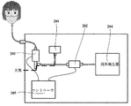
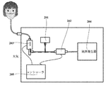
図2および図3は本実施例に係る共通の圧力センサーにより現在大気圧と通路圧力を測定することを示す概略図であり、圧力センサー201、呼吸弁202、補正弁203等の部材の状況が示されている。呼吸弁202は、スイッチ電磁弁であってもよく、補正弁203は2ポジション3ポートの電磁弁であってもよく、コントローラ205は、例えば、プリント回路基板(PCB、Printed Circuit Board)で実現でき、流体発生器204について、関連技術を参照できる。
本実施例では補正弁の「閉じ」「開き」は大気圧測定通路に対するものであり、具体的な弁動作は具体的に限定されないことに注意すべきである。また、本実施例における「通路圧力」とは、大気圧測定通路が開かれたときの流体搬送通路内の圧力をいい、大気圧測定通路が開かれているとき、圧力センサー201により測定するのは依然として流体搬送通路内の圧力であるが、このとき、「流体搬送通路内の圧力」は大気圧に同等し、説明の便宜上、本実施例において、測定大気圧と呼ぶことにする。
図2は、大気圧測定通路が開かれている状況を示しており、図2に示すように、呼吸弁202を閉じて補正弁203を開いたときに、図2における点線に示されているように、圧力センサー201は大気と連通できることによって、大気圧をリアルタイムに測定でき、このとき、流体搬送通路は閉じられている。
図3は流体搬送通路が開かれている状況を示しており、図3に示すように、呼吸弁202を開いて補正弁203を閉じたときに、図3における点線に示されているように、流体発生器204により発生された流体をユーザーに提供できるとともに、圧力センサー201は測定通路における圧力を測定でき、このとき、大気圧測定通路は閉じられている。
上記の図2および図3は本発明の実施例を概略的に説明するだけであり、ここに、本願と直接関連している一部の部材のみが概略的に示されているが、本発明はそれらに限らないことに注意すべきである。例えば、各部材の接続関係を適応的に調整してもよく、また、他の一部の部材を追加、または、そのうちのある部材を減少してもよい。当業者は上記内容に基づいて適応的に変形でき、上記図2および図3に記載のものに限られることはない。
本実施例において、当該流体搬送通路内における通路圧力を測定することによって、ユーザーの呼吸検知を行うことができる。例えば、測定されて得られた通路圧力値に基づいてユーザーの呼吸を検出できる(即ち、ユーザーの呼吸波形があるかを判断する)。本実施例において、一つの呼吸波形は、例えば、ユーザーが一回の完全な吸気と呼気の過程を完成することに対応していた通路圧力の分布状況を示す。
例えば、通路圧力値が規律的に変化すると、ユーザーの呼吸波形が存在すると確定され、また、測定されて得られた通路圧力値に基づいてユーザーの呼吸の波形図をさらに得ることができ、さらに測定されて得られた通路圧力値および/あるいは大気圧標準値に基づいて、ユーザーが吸気状態または呼気状態にあるかを判断できる。呼吸検知の具体的な内容について、さらに関連技術を参照してもよい。
本実施例において、呼吸検知により、流体の搬送、通路圧力の測定と大気圧の測定のそれぞれの動作をさらに正確に制御できる。これにより、ユーザーの呼吸状況に基づいて流体を提供し、流体搬送の効率を高めることができる。
以下、呼吸検知方法を参照しながら、流体の搬送、通路圧力の測定および大気圧の測定のそれぞれの動作を説明する。図4は、本発明の実施例の一つの実施の形態のみが例示的に示されており、具体的には、所定の周期に大気圧をリアルタイムに測定するとともに元の大気圧値を補正するという実施の形態を指すが、本発明はそれに限らないことに注意すべきである。
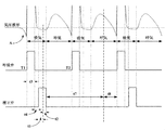
図4は本発明の実施例における共通の圧力センサーにより現在大気圧と通路圧力を測定するタイミングチャートである。図4に示すように、仮に呼吸弁と補正弁がともに閉じられるとし、このとき、通路内の圧力に変化がなく、図4における左上に示されている直線である。ユーザーが吸気し始めると、図4におけるAで示されているように、流体搬送通路内の圧力は下降し、対応する気圧波形が下降状態となり、当該圧力が一定の閾値(時刻T1)まで下降した後、コントローラは呼吸検知アルゴリズムでユーザーが吸気状態にあることを判断でき、呼吸弁を開くことができる。その後、流体搬送通路内は呼吸弁が開かれていることで流体が提供され、流体の濃度が迅速に上昇し、通路内の圧力が上昇する。
図4に示すように、呼吸弁が所定の時間t3(第2の所定時間)開かれた後、当該呼吸弁を閉じることができ、その後、呼吸弁が開かれることで流体搬送通路内に流体が提供されず、流体の濃度が迅速に下降し、通路内の圧力が下降する。圧力が一定の閾値まで下降した、または所定の時間t4(第3の所定時間)を経た後、気圧波形はほぼ穏やかになる傾向があり、補正弁を開く。
本実施例において、ユーザーの呼吸に基づいて第2の所定時間t3を調整できる。例えば、前に複数回測定されて得られたユーザー呼吸のサンプリングの頻度および/或いは通路内の内部圧力などの要素で決定でき、もしユーザーの吸気時間が長ければ(肺活量が大きければ)、t3を増大させることができ、もしユーザーの吸気時間が短ければ(肺活量が小さければ)、t3を減少させることができる。これにより、異なるユーザーの呼吸状態によって、呼吸検知と圧力測定をさらに正確に行うことができる。本実施例において、第3の所定時間t4は予め経験値に基づいて設定されてもよく、気圧波形がほぼ穏やかになる時間に基づいて設定されてもよい。
その後、図4に示すように、呼吸弁を閉じて補正弁を開いた所定の時間t1(第1の所定時間)後、気圧波形はほぼ穏やかな状態にあり、圧力センサーにより所定の第1の時間帯t2内に現在大気圧を測定できる。即ち、呼吸弁を閉じた(即ち、ユーザーに流体を供給しない)後、第1の所定時間t1と第1の時間帯t2内に、補正弁が開けている状態にあり、大気圧測定通路が開けられていた。第1の所定時間t1は、例えば、0.2秒であってもよく、第1の時間帯t2は、即ち、現在大気圧の収集時間であり、例えば、0.1秒であってもよい。
本実施例において、第1の所定時間t1は予め流体提供装置に設定された固定値であってもよく、ユーザーの呼吸の頻度ごとに設定されてもよい。例えば、図4に示すように、ユーザーが吸気する過程で呼吸波形がほぼ穏やかになる時間帯に基づいて第1の所定時間t1を設定できる。
図4に示すように、大気圧を測定し終わった後で、補正弁を閉じてから、ユーザーの呼吸状態を検出する呼吸検知アルゴリズムに測定されて得られた現在大気圧値を用いる。また、ユーザーが吸気状態にあると確定された時刻T2に、呼吸弁を再開し、ユーザーに流体を提供し、これ以降も類似する。
本実施例において、図4に示すように、呼吸弁を閉じて補正弁を開いた場合、当該圧力センサーにより第1の時間帯t2内に現在大気圧を測定できる。補正弁を閉じた場合、呼吸弁が閉じているかにもかかわらず、当該圧力センサーにより第1の時間帯t2とは異なる第2の時間帯内に通路圧力を測定できる。当該第1の時間帯(t2)は補正弁の開かれている時間(t1+t2)の一部であり、これにより、短い時間内に大気圧の測定をリアルタイムに完成でき、呼吸検知をさらに正確にできるだけでなく、他の動作に影響することなく、流体搬送の効率をさらに向上させることができる。また、ユーザーは当該流体提供装置を開いた後で、待つ必要がなく、当該装置を直ちに使用できる。
本実施例の上記の方法において、異なる時間帯に通路圧力と現在大気圧をそれぞれ測定することによって、通路圧力と現在大気圧の測定を互いに干渉させることなく、標準大気圧値に対する補正をさらに精確にすることができる。上記のタイミングチャートは本発明の例に過ぎないが、本発明はそれに限られないことに注意すべきである。
本実施例において、大気圧値は通常短時間内に大きく変化しないため、呼吸弁を閉じるたびに、現在大気圧を測定する必要がなく、即ち、ユーザーの複数回の呼吸に対して、1回の現在大気圧の測定を行うことができる。これにより、補正弁の頻繁的な開閉を回避できる。
具体的に、図4に示すように、例えば、2つの呼吸波形に対して1回の現在大気圧の測定を行うことができる。勿論、本実施例はそれに限らず、具体的にいくつの呼吸波形に対して1回の現在大気圧の測定を行うかについて、流体提供装置の置かれている環境などの要素に基づいて設定できる。
図4に示すように、補正弁を閉じて所定の時間t7を経た後、次回の大気圧の測定と補正を再び準備する。本実施例において、例えば、大気圧を測定し補正する一つの周期として、時間(t3+t4+t1+t2+t7+t8)にすることができる。所定の時間t7は予め設定された時間、例えば、30秒または1分間、あるいは、例えば、図4において約いくつかの呼吸波形に対応する時間であってもよく、t8はゼロ以上の数値であり、呼吸波形の検出時間に基づいて確定できる。また、呼吸を検出する具体的な内容について、関連技術を参照できる。
上記の図4に対する具体的な記載によりわかるように、本実施例において、ステップ104は、ユーザーが吸気状態にある場合、ユーザーに流体を提供するように流体搬送通路における呼吸弁を開くことを含むことができる。また、本実施例において、ステップ104は、呼吸弁を開いた後、所定の時間t3(第2の所定時間)を経て呼吸弁を閉じることと、当該呼吸弁を閉じた後、所定の時間t4(第3の所定時間)を経て補正弁を開くことと、所定の時間t1+t2(第4の所定時間)を経て当該補正弁を閉じることと、をさらに含むことができる。
本実施例において、ステップ103で複数回測定されて得られた大気圧値に基づいて呼吸検知のための大気圧標準値を補正することは、多くの補正方法を含むことができる。例えば、最新に測定されて得られた現在大気圧値を直接大気圧標準値にし、または、今回測定されて得られた現在大気圧値を前回測定されて得られた大気圧値に比較し、差値が予め設定された閾値よりも大きいとき、今回測定されて得られた現在大気圧値を大気圧標準値にし、または複数回測定されて得られた大気圧値を平均または重み付けた後で大気圧標準値にする。本発明の実施例はそれらに限られない。
本実施例において、複数回測定されて得られた大気圧値を平均または重み付けた後で大気圧標準値にすることを例として説明する。例えば、図4に示されている第1の時間帯t2において、例えば、五回のサンプリングで大気圧を測定することだけで、5つの大気圧値を得ることができ、その後、当該5つの大気圧値を平均または重み付け平均することで、平均または重み付け平均された値を現在大気圧にしてから、当該現在大気圧値を直接新しい大気圧標準値にし、当該新しい大気圧標準値を用いてユーザーの呼吸状態を検知する。
以上、各動作のタイミングチャートを概略的に説明した。以下、本実施例に係る流体提供方法をさらに説明する。
図5は本実施例に係る流体提供方法のフローチャート。図5に示すように、当該方法は、
初期の大気圧を測定し、ここに、例えば、流体提供装置のスイッチボタンを開いた直後、補正弁203を開いて呼吸弁202を閉じることで、流体提供装置の大気圧測定通路を開状態にし、圧力センサー201により初期の大気圧を一回に測定し、初期の大気圧値を取得するステップ501と、
補正弁203を閉じ、圧力センサー201により流体提供装置内の通路圧力を測定し、1つ以上の通路圧力値を取得するステップ502と、
ユーザーが吸気状態にあるかを判定し、ユーザーが吸気状態にあるとき、ステップ504を実行し、ユーザーが呼気状態にあるか、呼吸波形がないときに、ステップ502に戻し、ここに、測定されて得られた初期の大気圧値と測定されて得られた通路圧力値に基づいてユーザーの呼吸状態を検知するステップ503と、
呼吸弁202を開いて、ユーザーに流体を提供するステップ504と、
第2の所定時間t3を経た後、呼吸弁202を閉じて、ここに、第2の所定時間t3を上記のとおり設定できるステップ505と、
第3の所定時間t4を経た後、補正弁203を開いて、ここに、第3の所定時間t4を上記のとおり設定できるステップ506と、
第1の所定時間t1を経た後、在第1の時間帯t2内に圧力センサー201により現在大気圧を測定し、ここに、第1の所定時間t1を約0.2秒に設定でき、第1の時間帯t2を約0.1秒に設定できるステップ507と、
補正弁203を閉じるステップ508と、
測定されて得られた現在大気圧値に基づいて大気圧標準値を補正し、補正後の大気圧値と測定されて得られた通路圧力値に基づいてユーザーの呼吸状態を検知するステップ509と、を含む。
初期の大気圧を測定し、ここに、例えば、流体提供装置のスイッチボタンを開いた直後、補正弁203を開いて呼吸弁202を閉じることで、流体提供装置の大気圧測定通路を開状態にし、圧力センサー201により初期の大気圧を一回に測定し、初期の大気圧値を取得するステップ501と、
補正弁203を閉じ、圧力センサー201により流体提供装置内の通路圧力を測定し、1つ以上の通路圧力値を取得するステップ502と、
ユーザーが吸気状態にあるかを判定し、ユーザーが吸気状態にあるとき、ステップ504を実行し、ユーザーが呼気状態にあるか、呼吸波形がないときに、ステップ502に戻し、ここに、測定されて得られた初期の大気圧値と測定されて得られた通路圧力値に基づいてユーザーの呼吸状態を検知するステップ503と、
呼吸弁202を開いて、ユーザーに流体を提供するステップ504と、
第2の所定時間t3を経た後、呼吸弁202を閉じて、ここに、第2の所定時間t3を上記のとおり設定できるステップ505と、
第3の所定時間t4を経た後、補正弁203を開いて、ここに、第3の所定時間t4を上記のとおり設定できるステップ506と、
第1の所定時間t1を経た後、在第1の時間帯t2内に圧力センサー201により現在大気圧を測定し、ここに、第1の所定時間t1を約0.2秒に設定でき、第1の時間帯t2を約0.1秒に設定できるステップ507と、
補正弁203を閉じるステップ508と、
測定されて得られた現在大気圧値に基づいて大気圧標準値を補正し、補正後の大気圧値と測定されて得られた通路圧力値に基づいてユーザーの呼吸状態を検知するステップ509と、を含む。
本実施例において、流体提供方法は、前記補正弁が閉じられた場合、第5の所定時間を経た後、ユーザーの呼吸を検出することと、ユーザーの呼吸が検出されない(即ち、ユーザーの呼吸波形がない)場合、所定の時間t6(第6の所定時間)内にユーザーの呼吸を再検出することと、所定の時間t6内に依然としてユーザーの呼吸が検出されない場合、現在大気圧を測定することと、をさらに含むことができる。
本実施例の上記方法において、ユーザーの呼吸が検出されない(ユーザーの呼吸波形がない)と再び確定されると、即ち、ユーザーが当該流体提供装置を使用していないと確定されると、流体提供装置の現在大気圧値を強制的に測定することによって、いつでもユーザーが当該流体提供装置を使用し始める際に、当該ユーザーの呼吸状態をよりよく判定しやすくする。
本実施例において、流体提供方法は、ユーザーの呼吸が検出された(即ち、ユーザーの呼吸波形がある)場合、呼吸弁が開かれているかを確定することと、当該呼吸弁が開かれている場合、呼吸弁を閉じて補正弁を開くことによって現在大気圧を測定することと、当該呼吸弁が開かれていない場合、ユーザーの呼吸を検出し続けることと、をさらに含むことができる。
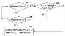
図6は本実施例に係る流体提供方法のもう1つのフローチャートである。図6に示すように、当該方法は、下記のステップを含む。
ユーザーの呼吸波形があるかを検出し、もし検出結果がはいであれば、ステップ602を実行し、さもなければ、ステップ603を実行するステップ601であって、
ここに、図5におけるステップ502の後で当該ステップ601を実施でき、例えば、流体搬送通路における補正弁が閉じられている場合、第5の所定時間t5を経た後、前記ユーザーの呼吸を検出する。当該ステップ601により、ユーザーが当該流体提供装置をまだ使用しているかを確定でき、当該第5の所定時間t5は予め設定されて流体提供装置に記憶されることができるとともに、t5はt7に等しくてもよく、勿論、ある場合t5はt7に等しくなくてもよく、呼吸を検出する方法について、具体的に関連技術を参照できる。
ここに、図5におけるステップ502の後で当該ステップ601を実施でき、例えば、流体搬送通路における補正弁が閉じられている場合、第5の所定時間t5を経た後、前記ユーザーの呼吸を検出する。当該ステップ601により、ユーザーが当該流体提供装置をまだ使用しているかを確定でき、当該第5の所定時間t5は予め設定されて流体提供装置に記憶されることができるとともに、t5はt7に等しくてもよく、勿論、ある場合t5はt7に等しくなくてもよく、呼吸を検出する方法について、具体的に関連技術を参照できる。
呼吸弁が開かれているかを確定し、もし判断結果がはいであれば、ステップ604を実行し、さもなければステップ601に戻るステップ602である。
これにより、呼吸弁がONであるかを大気圧測定をリアルタイムに行うかの条件にすることによって、大気圧の測定とユーザー呼吸とを関連付けることができ、よって、ユーザーの呼吸状態に基づいて、大気圧の測定を正確に行うことができ、呼吸検知の精度を高めることができるだけでなく、流体搬送の効率を向上させることもできる。
第6の所定時間t6内にユーザーの呼吸波形があるかを再び確定し、もし判断結果がはいであれば、ステップ602を実行し、さもなければ、ステップ604を実行するステップ603である。ここに、第6の所定時間t6は予め設定され当該流体提供装置に記憶されることができる。
これにより、大気圧測定を強制的に行い、呼吸検知の精度を高めることができる。
呼吸弁202を閉じて補正弁203を開くことによって、大気圧を測定して補正するステップ604である。
呼吸弁202を閉じて補正弁203を開くことによって、大気圧を測定して補正するステップ604である。
本実施例において、ステップ604は、図5におけるステップ505乃至ステップ509に対応でき、即ち、図6と図5とを組み合わせて実施できる。また、呼吸弁202は例えば、開かれたt3時間帯の後に閉じられ、呼吸弁202を閉じる時刻と補正弁203を開く時刻について、上記の説明を参照できる。
上記の図5と6は本発明の実施例を概略的に説明しただけであるが、本発明はそれに限られないことに注意すべきである。例えば、各ステップ間の実行順序を適切に調整でき、さらに他のあるステップを追加、またはそのうちのあるステップを減少してもよい。当業者は上記内容に基づいて適切に変形でき、上記の図5と6の記載だけに限られない。また、図5と6とを組み合わせて実施できる。
現在、従来の流体提供機器はユーザーに流体を提供する前に、大気圧を1回に測定してから、検知されたユーザーの吸気状態に基づいて流体を提供する必要がある一方、本願の実施例に係る流体提供装置は上記の動作フローを有して、開かれた後でユーザーに直接使用されることができ、さらに後続的な使用過程で大気圧値をリアルタイムに補正できる。
本実施例に係る流体提供方法により、呼吸検知のための大気圧標準値を補正できるため、流体提供装置の外部の現在大気圧値を用いてユーザーの呼吸状態を検知(検出)する根拠にすることができ、これにより、大気圧の変化による呼吸状態に対する誤判定を減少または回避でき、呼吸検知の精度を高めることができる。
実施例2
本実施例2は実施例1に記載の流体提供方法を実行するための流体提供装置を提供している。当該流体提供装置は、例えば、酸素製造機、霧化器などであってもよい。流体提供装置に提供される流体は酸素、霧化を行うためのガスおよび/或いは液体などであってもよい。本実施例はそれを限定することなく、実際の必要に応じて使用される流体提供装置の具体的なタイプを選択することができる。本実施例の実施例1と同様な内容について説明を省略する。
本実施例2は実施例1に記載の流体提供方法を実行するための流体提供装置を提供している。当該流体提供装置は、例えば、酸素製造機、霧化器などであってもよい。流体提供装置に提供される流体は酸素、霧化を行うためのガスおよび/或いは液体などであってもよい。本実施例はそれを限定することなく、実際の必要に応じて使用される流体提供装置の具体的なタイプを選択することができる。本実施例の実施例1と同様な内容について説明を省略する。
図7は本実施例に係る流体提供装置の概略図である。図7に示すように、流体提供装置700は圧力センサー701、判定部706、補正部702および制御部703を含む。
そのうち、圧力センサー701はリアルタイムに流体提供装置700の外部の現在大気圧を複数回測定するとともに、流体提供装置700の流体搬送通路内の通路圧力を測定するために用いられ、判定部706は、測定されて得られた流体搬送通路内の通路圧力値と大気圧標準値に基づいてユーザーが吸気状態にあるかを判断するために用いられ、補正部702は複数回測定されて得られた大気圧値に基づいて呼吸検知のための大気圧標準値を補正するために用いられ、制御部703は流体提供装置700の内部の通路圧力値と補正後の大気圧標準値に基づいて流体提供装置700の流体搬送通路の開閉を制御するために用いられる。
本実施例において、圧力センサー701は、異なる時間帯内に現在大気圧と通路圧力をそれぞれ測定する。圧力センサー701の現在大気圧と通路圧力を測定する具体的な時間と手段について、上記の実施例1を参照し、ここで説明を省略する。
本実施例において、図7に示すように、流体提供装置700は流体搬送通路に設けられた呼吸弁704と補正弁705をさらに含んでもよく、呼吸弁704が開、補正弁705が閉であるとき、流体提供装置700はユーザーに流体を提供し、呼吸弁704が閉、補正弁705が開であるとき、現在大気圧の測定を行うように圧力センサー701は外部大気と連通する。補正弁705は、例えば、2ポジション3ポートの弁であってもよく、一方は流体搬送通路を導通させ、他方は大気圧測定通路を導通させることができる。
本実施例において、判定部706、補正部702および/或いは制御部703は任意のソフトウェア、ハードウェア、ファームウェアまたはそれらの組合せによって実現可能である。1つの実施の形態において、判定部706、補正部702および/或いは制御部703の機能はプロセッサーに集積され実現可能であり、判定部706、補正部702および/或いは制御部703の機能を実現するために、当該プロセッサーをメモリからプログラムを読取して実行するように配置することができる。
以上は本発明に関連する各部材またはモジュールについてのみ説明したが、本発明はこれに限られないことに注意すべきである。本実施例に係る流体提供装置は、従来技術における他の部材をさらに含んでもよく、ここでは説明を省略する。これらの部品やモジュールの具体的な内容について、関連技術を参照できる。
また、簡単のために、図7では各部材やモジュール間の接続関係や信号の流れを例示しているだけであるが、当業者にとって、バス接続などの様々な関連技術を採用できることは自明である。上記の各部材やモジュールは、例えば、プロセッサー、メモリなどのハードウェア施設で実現でき、本発明の実施はそれを限定しない。
本実施例に係る流体提供装置により、呼吸検知のための大気圧標準値を補正できることによって、流体提供装置の外部の現在大気圧値を用いてユーザーの呼吸状態を検知(検出)するための根拠とすることができ、よって、大気圧の変化による呼吸状態に対する誤判定を減少または回避し、呼吸検知の精度を高めることができる。
本発明の実施例はプロセッサー読取可能プログラムをさらに提供し、当該プログラムはプロセッサーに下記のステップを実行させ、流体提供装置の内部の通路圧力値とリアルタイムに補正された後の大気圧標準値に基づいて流体提供装置の流体搬送通路を制御する。
本発明の実施例はプロセッサー読取可能プログラムが記憶された記憶媒体をさらに提供しており、当該プロセッサー読取可能プログラムはプロセッサーに下記のステップを実行させ、流体提供装置の内部の通路圧力値とリアルタイムに補正された後の大気圧標準値に基づいて流体提供装置の流体搬送通路を制御する。
本発明の上記の方法/システムはハードウェアで実現可能であり、ハードウェアにソフトウェアを組み合わせることで実現可能である。本発明はこのようなコンピュータ読取可能プログラムに関し、当該プログラムがロジック部材に実行されるとき、当該ロジック部材に、上記記載の装置または構成部材を実現させ、あるいは当該ロジック部材に上記記載の各種の方法またはステップを実現させることができる。ロジック部材は、例えば、フィールドプログラマブルロジック部材、マイクロプロセッサー、コンピュータで使用されるプロセッサーなどである。本発明は、上記のプログラムを記憶するための記憶媒体、たとえば、ハードディスク、磁気ディスク、光ディスク、DVD、flashメモリなどにさらに関する。
本発明の実施例に記載の方法/システムを参照すると、ハードウェア、プロセッサーにより実行されるソフトウェアモジュールまたは両者の組合せに直接表現できる。例えば、図に示されている機能ブロック図における一つ以上および/或いは機能ブロック図の一つ以上の組み合わせは、コンピュータのプログラムフローの各ソフトウェアモジュールにも対応でき、各ハードウェアモジュールにも対応できる。これらのソフトウェアモジュールは、それぞれ図に示されている各ステップに対応できる。これらのハードウェアモジュールは、例えば、フィールドプログラマブルゲートアレイ(FPGA)によりこれらのソフトウェアモジュールを固化させて実現できる。
ソフトウェアモジュールは、RAMメモリ、フラッシュメモリ、ROMメモリ、EPROMメモリ、EEPROMメモリ、レジスタ、ハードディスク、リムーバブルディスク、CD-ROMまたは本分野の既知の任意の他の形式の記憶媒体に位置してもよい。1種類の記憶媒体をプロセッサーに結合することによって、プロセッサーが当該記憶媒体から情報を読み取るようにするとともに、当該記憶媒体に情報を書き込むことができ、あるいは、当該記憶媒体は、プロセッサーの構成部分であってもよい。プロセッサーと記憶媒体はASICに位置してもよい。当該ソフトウェアモジュールを機器のメモリに記憶してもよく、挿入可能な機器のメモリカードに記憶してもよい。例えば、機器に大容量のMEGA-SIMカードまたは大容量のフラッシュメモリ装置を採用している場合、そのソフトウェアモジュールは、当該MEGA-SIMカードまたは大容量のフラッシュメモリ装置に記憶できる。
図に記載の機能ブロックにおける一つ以上、および/或いは機能ブロックの一つ以上の組合せに対して、本発明に記載の機能を実行するための汎用プロセッサー、デジタル信号プロセッサー(DSP)、専用集積回路(ASIC)、フィールドプログラマブルゲートアレイ(FPGA)または他のプログラマブルロジックデバイス、ディスクリートゲートまたはトランジスタロジックデバイス、ディスクリートハードウェアコンポーネントまたはその任意の適切な組み合わせとして実現することができる。図に記載の機能ブロックにおける一つ以上、および/或いは機能ブロックにおける一つ以上の組合せに対して、さらに計算設備の組み合わせ、例えば、DSPとマイクロプロセッサーの組み合わせ、複数のマイクロプロセッサー、DSPと通信結合された一つ以上のマイクロプロセッサー、あるいはその他のこのような配置として実現することもできる。
以上、具体的な実施形態を参照しながら本願を記載したが、当業者は、これらの記載は例示的なものであり、本願の特許請求する範囲を制限するものではないことはよくわかっている。当業者は、本願の原理に基づいて本願に対して各種の変形および補正を行うことができる。これらの変形および補正も本発明の範囲内に属する。
Claims (14)
- 流体提供装置における圧力センサーによりリアルタイムに前記流体提供装置の外部の現在大気圧を複数回測定するとともに、前記圧力センサーにより前記流体提供装置の流体搬送通路内の通路圧力を測定すること、
前記流体搬送通路内の通路圧力値と大気圧標準値に基づいてユーザーが吸気状態にあるか否かを判定すること、
複数回測定されて得られた大気圧値に基づいて前記大気圧標準値を補正すること、および
前記通路圧力値と補正後の大気圧標準値に基づいて前記流体搬送通路の開閉を制御することを含むことを特徴とする流体提供方法。 - 前記圧力センサーは、異なる時間帯内に、前記現在大気圧と前記通路圧力をそれぞれ測定する
ことを特徴とする請求項1に記載の流体提供方法。 - 前記流体搬送通路における呼吸弁を閉じて前記流体搬送通路における補正弁を開いた第1の所定時間の後、前記圧力センサーにより、所定の第1の時間帯内に、前記現在大気圧を測定する
ことを特徴とする請求項2に記載の流体提供方法。 - 前記補正弁を閉じた場合、前記圧力センサーにより、前記第1の時間帯と異なる第2の時間帯内に前記通路圧力を測定する
ことを特徴とする請求項3に記載の流体提供方法。 - 前記通路圧力値と補正後の大気圧標準値に基づいて前記流体搬送通路の開閉を制御することは、
前記ユーザーが前記吸気状態にある場合、前記ユーザーに流体を提供するように、前記流体搬送通路における呼吸弁を開く
ことを含むことを特徴とする請求項1に記載の流体提供方法。 - 前記通路圧力値と補正後の大気圧標準値に基づいて前記流体搬送通路の開閉を制御することは、
前記呼吸弁を開いて第2の所定時間を経った後、前記呼吸弁を閉じること、
前記呼吸弁を閉じて第3の所定時間を経った後、前記流体搬送通路における補正弁を開くこと、および
第4の所定時間を経った後、前記補正弁を閉じることをさらに含む
ことを特徴とする請求項5に記載の流体提供方法。 - 前記ユーザーの呼吸により前記第2の所定時間を調整することをさらに含む
ことを特徴とする請求項6に記載の流体提供方法。 - 前記流体搬送通路における補正弁が閉じている場合、第5の所定時間を経った後、前記ユーザーの呼吸を検出すること、
前記ユーザーの呼吸が検出されていない場合、第6の所定時間内に前記ユーザーの呼吸を再検出すること、および
前記第6の所定時間内に前記ユーザーの呼吸がまだ検出されていな場合、前記現在大気圧を測定することをさらに含む
ことを特徴とする請求項3~7のいずれか一項に記載の流体提供方法。 - 前記ユーザーの呼吸が検出されている場合、前記流体搬送通路における呼吸弁が開かれているか否かを確定すること、および
前記呼吸弁が開かれている場合、前記現在大気圧を測定するように前記呼吸弁を閉じて前記補正弁を開き、前記呼吸弁が開かれていない場合、前記ユーザーの呼吸を引き続き検出することをさらに含む
ことを特徴とする請求項8に記載の流体提供方法。 - 前記ユーザーの複数回の呼吸に対し前記現在大気圧の測定を一回行う
ことを特徴とする請求項8に記載の流体提供方法。 - 前記複数回測定されて得られた大気圧値に基づいて前記大気圧標準値を補正することは、
最新測定されて得られた現在大気圧値を前記大気圧標準値とすること、または
今回測定されて得られた現在大気圧値を前回測定されて得られた大気圧値と比較し、差値が予め設定された閾値よりも大きい場合、前記今回測定されて得られた現在大気圧値を前記大気圧標準値とすること、または
前記複数回測定されて得られた大気圧値を平均または重み付けた後、前記大気圧標準値とすることを含む
ことを特徴とする請求項1~7のいずれか一項に記載の流体提供方法。 - リアルタイムに流体提供装置の外部の現在大気圧を複数回測定するとともに前記流体提供装置の流体搬送通路内の通路圧力を測定するための圧力センサー、
前記流体搬送通路内の通路圧力値と大気圧標準値に基づいてユーザーが吸気状態にあるか否かを判定するための判定部、
複数回測定されて得られた大気圧値に基づいて前記大気圧標準値を補正するための補正部、および
前記流体提供装置の内部の通路圧力値と補正後の大気圧標準値に基づいて前記流体搬送通路の開閉を制御するための制御部を含む
ことを特徴とする流体提供装置。 - 前記圧力センサーは、異なる時間帯内に、前記現在大気圧と前記通路圧力をそれぞれ測定する
ことを特徴とする請求項12に記載の流体提供装置。 - 前記流体搬送通路に設けられた呼吸弁と補正弁をさらに含み、前記呼吸弁が開、前記補正弁が閉であるとき、前記流体提供装置はユーザーに流体を提供し、前記呼吸弁が閉、前記補正弁が開であるとき、前記現在大気圧の測定を行うように、前記圧力センサーは外部大気と連通する
ことを特徴とする請求項13に記載の流体提供装置。
Applications Claiming Priority (2)
| Application Number | Priority Date | Filing Date | Title |
|---|---|---|---|
| CN201910198463.6 | 2019-03-15 | ||
| CN201910198463.6A CN111686352B (zh) | 2019-03-15 | 2019-03-15 | 流体提供方法以及流体提供装置 |
Publications (1)
| Publication Number | Publication Date |
|---|---|
| WO2020189152A1 true WO2020189152A1 (ja) | 2020-09-24 |
Family
ID=72475323
Family Applications (1)
| Application Number | Title | Priority Date | Filing Date |
|---|---|---|---|
| PCT/JP2020/006329 Ceased WO2020189152A1 (ja) | 2019-03-15 | 2020-02-18 | 流体提供方法および流体提供装置 |
Country Status (2)
| Country | Link |
|---|---|
| CN (1) | CN111686352B (ja) |
| WO (1) | WO2020189152A1 (ja) |
Cited By (2)
| Publication number | Priority date | Publication date | Assignee | Title |
|---|---|---|---|---|
| CN115177826A (zh) * | 2021-04-01 | 2022-10-14 | 康泰医学系统(秦皇岛)股份有限公司 | 一种网孔雾化器 |
| CN117815499A (zh) * | 2023-12-26 | 2024-04-05 | 深圳融昕医疗科技有限公司 | 大气压传感器自检方法、系统、电子设备及可读存储介质 |
Citations (2)
| Publication number | Priority date | Publication date | Assignee | Title |
|---|---|---|---|---|
| JP2001029472A (ja) * | 1999-07-22 | 2001-02-06 | Daikin Ind Ltd | 呼吸同調器 |
| JP2006006521A (ja) * | 2004-06-24 | 2006-01-12 | Daikin Ind Ltd | 医療機器 |
Family Cites Families (13)
| Publication number | Priority date | Publication date | Assignee | Title |
|---|---|---|---|---|
| AU711313B2 (en) * | 1995-07-03 | 1999-10-07 | Resmed Limited | Auto-calibration of pressure transducer offset |
| US6164276A (en) * | 1997-05-16 | 2000-12-26 | Datex-Ohmeda, Inc. | Accurate dose nitric oxide pulse delivery device with monitoring and alarms |
| DE10014959C1 (de) * | 2000-03-25 | 2001-05-03 | Draeger Medizintech Gmbh | Vorrichtung zur Messung eines Atemgasbestandteils in einer Atemgasleitung |
| WO2005113045A1 (en) * | 2004-04-20 | 2005-12-01 | Crutchfield Clifton D | Respirator fit-testing apparatus and method |
| US8561611B2 (en) * | 2005-06-21 | 2013-10-22 | Ric Investments, Llc | Respiratory device measurement system |
| AU2006262588A1 (en) * | 2005-06-21 | 2007-01-04 | Ric Investments, Llc | Respiratory device measurement system |
| JP2007190277A (ja) * | 2006-01-20 | 2007-08-02 | Omron Healthcare Co Ltd | 呼吸訓練器および呼吸訓練プログラム |
| CN101543655A (zh) * | 2009-04-29 | 2009-09-30 | 江苏万泰科技股份有限公司 | 一种脉冲供氧时探测呼吸状态的方法 |
| US20120097164A1 (en) * | 2010-10-20 | 2012-04-26 | Deborah Anne Rozario | Apparatuses and methods for positive expiratory pressure therapy |
| US9943249B2 (en) * | 2015-07-14 | 2018-04-17 | Darryl Zitting | Respiratory gas monitor testing system and methods of use |
| CA3005443A1 (en) * | 2015-11-16 | 2017-05-26 | Respirix, Inc. | Devices and methods for monitoring physiologic parameters |
| RU167390U1 (ru) * | 2016-06-21 | 2017-01-10 | Публичное акционерное общество "Техприбор" | Аппарат неинвазивной искусственной вентиляции легких новорожденных |
| CN108066863A (zh) * | 2016-11-16 | 2018-05-25 | 北京航天长峰股份有限公司 | 一种高可靠性麻醉呼吸机通气方法 |
-
2019
- 2019-03-15 CN CN201910198463.6A patent/CN111686352B/zh active Active
-
2020
- 2020-02-18 WO PCT/JP2020/006329 patent/WO2020189152A1/ja not_active Ceased
Patent Citations (2)
| Publication number | Priority date | Publication date | Assignee | Title |
|---|---|---|---|---|
| JP2001029472A (ja) * | 1999-07-22 | 2001-02-06 | Daikin Ind Ltd | 呼吸同調器 |
| JP2006006521A (ja) * | 2004-06-24 | 2006-01-12 | Daikin Ind Ltd | 医療機器 |
Cited By (2)
| Publication number | Priority date | Publication date | Assignee | Title |
|---|---|---|---|---|
| CN115177826A (zh) * | 2021-04-01 | 2022-10-14 | 康泰医学系统(秦皇岛)股份有限公司 | 一种网孔雾化器 |
| CN117815499A (zh) * | 2023-12-26 | 2024-04-05 | 深圳融昕医疗科技有限公司 | 大气压传感器自检方法、系统、电子设备及可读存储介质 |
Also Published As
| Publication number | Publication date |
|---|---|
| CN111686352A (zh) | 2020-09-22 |
| CN111686352B (zh) | 2023-07-14 |
Similar Documents
| Publication | Publication Date | Title |
|---|---|---|
| JP7829527B2 (ja) | 一酸化窒素供給システム | |
| US8434479B2 (en) | Flow rate compensation for transient thermal response of hot-wire anemometers | |
| JP5995942B2 (ja) | 人工呼吸器リーク補償 | |
| US20130006134A1 (en) | Methods and systems for monitoring volumetric carbon dioxide | |
| EP2183011B1 (en) | A patient ventilation system with gas identification means | |
| EP3292408B1 (en) | Breath gas analysis systems and methods | |
| CN101288791A (zh) | 一种麻醉机呼吸装置及其流量传感器的标定方法 | |
| WO2023045216A1 (zh) | 呼吸机自动计量校准方法、装置及存储介质 | |
| CN101543655A (zh) | 一种脉冲供氧时探测呼吸状态的方法 | |
| CN111686352B (zh) | 流体提供方法以及流体提供装置 | |
| Duprez et al. | High-flow nasal cannula therapy, factors affecting effective inspired oxygen fraction: an experimental adult bench model | |
| CN103893882B (zh) | 一种麻醉机流量修正方法和装置 | |
| CN105983164A (zh) | 一种提高潮气量控制精度的方法 | |
| CN114748748A (zh) | 一种通气设备及呼气流量的修正方法 | |
| CN206146477U (zh) | 一种提高流量测量精度的装置 | |
| CN116326851B (zh) | 一种气流传感器、气流检测方法及电子烟 | |
| CN104605856A (zh) | 双腔体积描记箱 | |
| CN118286551A (zh) | 基于目标对象的机械通气管理方法、装置、呼吸机及介质 | |
| CN104835300A (zh) | 多种气体检测报警器自动检测系统及方法 | |
| CN102506965A (zh) | 一种流量传感器校准系统 | |
| US20220184330A1 (en) | Control device and method for ventilation therapy equipment, and ventilation therapy equipment | |
| WO2020022379A1 (ja) | 呼吸検知方法及びシステム、ガス供給方法及びシステム、ならびに酸素発生器 | |
| CN118593851B (zh) | 一种麻醉机的流量指示方法、装置、电子设备及存储介质 | |
| CN205568469U (zh) | 烟草销售柜 | |
| Qiao et al. | The detection and estimation of the air leakage in noninvasive ventilation: Platform study |
Legal Events
| Date | Code | Title | Description |
|---|---|---|---|
| 121 | Ep: the epo has been informed by wipo that ep was designated in this application |
Ref document number: 20773193 Country of ref document: EP Kind code of ref document: A1 |
|
| NENP | Non-entry into the national phase |
Ref country code: DE |
|
| 122 | Ep: pct application non-entry in european phase |
Ref document number: 20773193 Country of ref document: EP Kind code of ref document: A1 |
|
| NENP | Non-entry into the national phase |
Ref country code: JP |