WO2020189125A1 - カフユニット、カフユニットの製造方法、及び血圧測定装置 - Google Patents
カフユニット、カフユニットの製造方法、及び血圧測定装置 Download PDFInfo
- Publication number
- WO2020189125A1 WO2020189125A1 PCT/JP2020/005959 JP2020005959W WO2020189125A1 WO 2020189125 A1 WO2020189125 A1 WO 2020189125A1 JP 2020005959 W JP2020005959 W JP 2020005959W WO 2020189125 A1 WO2020189125 A1 WO 2020189125A1
- Authority
- WO
- WIPO (PCT)
- Prior art keywords
- cuff
- carla
- sheet
- air bag
- bag
- Prior art date
- Legal status (The legal status is an assumption and is not a legal conclusion. Google has not performed a legal analysis and makes no representation as to the accuracy of the status listed.)
- Ceased
Links
Images


Classifications
-
- A—HUMAN NECESSITIES
- A61—MEDICAL OR VETERINARY SCIENCE; HYGIENE
- A61B—DIAGNOSIS; SURGERY; IDENTIFICATION
- A61B5/00—Measuring for diagnostic purposes; Identification of persons
- A61B5/02—Detecting, measuring or recording for evaluating the cardiovascular system, e.g. pulse, heart rate, blood pressure or blood flow
- A61B5/021—Measuring pressure in heart or blood vessels
- A61B5/02141—Details of apparatus construction, e.g. pump units or housings therefor, cuff pressurising systems, arrangements of fluid conduits or circuits
-
- A—HUMAN NECESSITIES
- A61—MEDICAL OR VETERINARY SCIENCE; HYGIENE
- A61B—DIAGNOSIS; SURGERY; IDENTIFICATION
- A61B5/00—Measuring for diagnostic purposes; Identification of persons
- A61B5/02—Detecting, measuring or recording for evaluating the cardiovascular system, e.g. pulse, heart rate, blood pressure or blood flow
- A61B5/021—Measuring pressure in heart or blood vessels
- A61B5/022—Measuring pressure in heart or blood vessels by applying pressure to close blood vessels, e.g. against the skin; Ophthalmodynamometers
- A61B5/02233—Occluders specially adapted therefor
- A61B5/02241—Occluders specially adapted therefor of small dimensions, e.g. adapted to fingers
-
- A—HUMAN NECESSITIES
- A61—MEDICAL OR VETERINARY SCIENCE; HYGIENE
- A61B—DIAGNOSIS; SURGERY; IDENTIFICATION
- A61B5/00—Measuring for diagnostic purposes; Identification of persons
- A61B5/02—Detecting, measuring or recording for evaluating the cardiovascular system, e.g. pulse, heart rate, blood pressure or blood flow
- A61B5/021—Measuring pressure in heart or blood vessels
- A61B5/022—Measuring pressure in heart or blood vessels by applying pressure to close blood vessels, e.g. against the skin; Ophthalmodynamometers
- A61B5/0235—Valves specially adapted therefor
-
- A—HUMAN NECESSITIES
- A61—MEDICAL OR VETERINARY SCIENCE; HYGIENE
- A61B—DIAGNOSIS; SURGERY; IDENTIFICATION
- A61B5/00—Measuring for diagnostic purposes; Identification of persons
- A61B5/68—Arrangements of detecting, measuring or recording means, e.g. sensors, in relation to patient
- A61B5/6801—Arrangements of detecting, measuring or recording means, e.g. sensors, in relation to patient specially adapted to be attached to or worn on the body surface
- A61B5/6802—Sensor mounted on worn items
- A61B5/681—Wristwatch-type devices
-
- A—HUMAN NECESSITIES
- A61—MEDICAL OR VETERINARY SCIENCE; HYGIENE
- A61B—DIAGNOSIS; SURGERY; IDENTIFICATION
- A61B5/00—Measuring for diagnostic purposes; Identification of persons
- A61B5/68—Arrangements of detecting, measuring or recording means, e.g. sensors, in relation to patient
- A61B5/6801—Arrangements of detecting, measuring or recording means, e.g. sensors, in relation to patient specially adapted to be attached to or worn on the body surface
- A61B5/6843—Monitoring or controlling sensor contact pressure
-
- A—HUMAN NECESSITIES
- A61—MEDICAL OR VETERINARY SCIENCE; HYGIENE
- A61B—DIAGNOSIS; SURGERY; IDENTIFICATION
- A61B2560/00—Constructional details of operational features of apparatus; Accessories for medical measuring apparatus
- A61B2560/04—Constructional details of apparatus
-
- A—HUMAN NECESSITIES
- A61—MEDICAL OR VETERINARY SCIENCE; HYGIENE
- A61B—DIAGNOSIS; SURGERY; IDENTIFICATION
- A61B2562/00—Details of sensors; Constructional details of sensor housings or probes; Accessories for sensors
- A61B2562/02—Details of sensors specially adapted for in-vivo measurements
- A61B2562/0247—Pressure sensors
-
- A—HUMAN NECESSITIES
- A61—MEDICAL OR VETERINARY SCIENCE; HYGIENE
- A61B—DIAGNOSIS; SURGERY; IDENTIFICATION
- A61B2562/00—Details of sensors; Constructional details of sensor housings or probes; Accessories for sensors
- A61B2562/12—Manufacturing methods specially adapted for producing sensors for in-vivo measurements
-
- A—HUMAN NECESSITIES
- A61—MEDICAL OR VETERINARY SCIENCE; HYGIENE
- A61B—DIAGNOSIS; SURGERY; IDENTIFICATION
- A61B5/00—Measuring for diagnostic purposes; Identification of persons
- A61B5/74—Details of notification to user or communication with user or patient; User input means
- A61B5/742—Details of notification to user or communication with user or patient; User input means using visual displays
Definitions
- the present invention relates to a cuff unit used in a blood pressure measuring device, a method for manufacturing the cuff unit, and a blood pressure measuring device.
- blood pressure measuring devices used for measuring blood pressure have been used as a means for checking the health condition not only in medical equipment but also in the home.
- the blood pressure measuring device for example, expands and contracts a cuff wrapped around the upper arm or wrist of a living body, and detects the pressure of the cuff with a pressure sensor to detect the vibration of the arterial wall and measure the blood pressure.
- a cuff used in such a blood pressure measuring device for example, as disclosed in Japanese Patent Application Laid-Open No. 11-309119, a technique of inflating a plurality of air bags to compress an artery is known (for example, , Patent Document 1).
- the sensing cuff expands in the direction of pressure closure of the blood vessel, and the sensing cuff is required to come into close contact with the wrist when inflated. Therefore, in order to bring the inflated sensing cuff into close contact with the wrist, there is known a technique of using a carla between the belt for fixing the blood pressure measuring device to the wrist and the sensing cuff.
- such a blood pressure measuring device may have a configuration in which a pressing cuff that presses the sensing cuff against the wrist is fixed to the inner peripheral surface of the carla in order to bring the sensing cuff into close contact with the wrist.
- an object of the present invention is to provide a cuff unit capable of suppressing the displacement of the pressing cuff and the sensing cuff with respect to the carla, a method for manufacturing the cuff unit, and a blood pressure measuring device.
- a cuff unit including a sensing cuff formed in a second bag-shaped structure and including a joining allowance joined to the first bag-shaped structure adjacent to the second bag-shaped structure.
- the cuff includes a one- or multi-layered bag-like structure that is wrapped around the wrist or the like of a living body when measuring blood pressure and expands by being supplied with a fluid.
- the bag-shaped structure expands by a fluid, and when the fluid is air, it is an air bag.
- the pressing cuff and the sensing cuff can be fixed to the carla as an integral body. .. Therefore, since the pressing cuff and the sensing cuff can be fixed by one attachment work to the carla, the position of the pressing cuff and the sensing cuff to the carla is compared with the configuration in which the pressing cuff and the sensing cuff are fixed to the carla separately. The deviation can be suppressed. Further, it is possible to prevent the expansion of the pressing cuff from being hindered by the joining allowance.
- the first bag-shaped structure is formed in a long shape in one direction
- the second bag-shaped structure is formed in a long shape in one direction
- the joining allowance is the same.
- a cuff unit formed at an outer edge portion along the longitudinal direction of the second bag-shaped structure and joined to the outer edge portion along the longitudinal direction of the first bag-shaped structure.
- the joining allowance is joined over a wide range of the first bag-shaped structure. As a result, it is possible to prevent water such as sweat from the user from entering between the pressing cuff and the sensing cuff.
- the cuff unit of the above aspect is provided in which the pressing cuff and the sensing cuff are curved according to the inner peripheral surface of the carla.
- a cuff unit which is arranged between the pressing cuff and the sensing cuff and includes the pressing cuff and a back plate joined to the sensing cuff.
- the integrated body of the pressing cuff, the back plate, and the sensing cuff can be fixed to the carla with a single attachment work, so that the number of manufacturing steps of the blood pressure measuring device can be reduced.
- the first structure including the pressing cuff is arranged on the previously described mounting surface of the jig having the mounting surface formed on the curved surface corresponding to the surface to which the pressing cuff of the carla is joined.
- the first structure is positioned with respect to the described surface
- a second structure including a sensing cuff is arranged on the first structure
- the second structure is positioned with respect to the previously described surface.
- Provided is a method for manufacturing a cuff unit, which joins and integrates a first structure and the second structure.
- the mounting surface formed on the curved surface corresponding to the surface on which the pressing cuff of the carla is fixed means that the cuff unit is the carla when the cuff unit formed along the mounting surface is fixed to the carla. It is a curved surface that can suppress the occurrence of wrinkles that inhibit expansion on at least one of the pressing cuff and the sensing cuff by being curved as compared with that before being fixed to.
- the curved surface of the carla corresponding to the surface on which the pressing cuff is arranged is, for example, a curved surface of the carla having the same curvature as the surface on which the pressing cuff is arranged.
- the curved surface of Carla corresponding to the surface on which the pressing cuff is placed is a curved surface of Carla having substantially the same curvature as the surface on which the pressing cuff is placed.
- the pressing cuff and the sensing cuff are integrally fixed by using a jig having a mounting surface formed on a curved surface corresponding to the surface on which the pressing cuff is fixed.
- the sensing cuff can be fixed integrally in a curved posture.
- the pressing cuff and the sensing cuff are integrally fixed by using a jig having a flat mounting surface to form a cuff unit
- the cuff unit is aligned with the flat mounting surface and the upper surface of the sensing cuff is adjusted. Is configured to be flat.
- the pressing cuff and the sensing cuff may be wrinkled due to the difference between the inner and outer circumferences caused by the cuff unit being curved according to the shape of the carla.
- the method for manufacturing a cuff unit is such that the second structure includes a joining allowance, and the first structure and the second structure are joined by the joining allowance. Provided.
- a method for manufacturing a cuff unit in which a second structure is arranged and the second structure is joined to the first structure and the back plate.
- the integrated body of the pressing cuff, the back plate, and the sensing cuff can be fixed to the carla with a single attachment work, so that the number of manufacturing steps of the blood pressure measuring device can be reduced.
- the jig has a plurality of positioning pins
- the first structure has a plurality of holes for arranging the positioning pins
- the second structure has the positioning pins.
- the joining allowance has a plurality of holes for arranging the positioning pins
- the plurality of positioning pins are set in the plurality of holes of the first structure and the plurality of holes of the second structure.
- the first structure and the second structure each include a cutting allowance, and the first structure and the second structure are fixed and integrated. Later, a method for manufacturing a cuff unit for cutting the cutting allowance is provided.
- the work efficiency of manufacturing the cuff unit can be improved by fixing and integrating the first structure and the second structure and then cutting.
- a carla and a plurality of first bag-like structures stacked and each inflated by a fluid are included, a pressing cuff joined to the carla, and one second bag-like structure inflated by the fluid.
- a cuff unit including a body and a sensing cuff formed on the second bag-shaped structure and joined to the first bag-shaped structure adjacent to the second bag-shaped structure, and the cuff unit.
- a blood pressure measuring device including a device main body for supplying the fluid.
- the pressing cuff and the sensing cuff can be fixed to the carla as an integral body. .. Therefore, since the pressing cuff and the sensing cuff can be fixed by one attachment work to the carla, the position of the pressing cuff and the sensing cuff to the carla is compared with the configuration in which the pressing cuff and the sensing cuff are fixed to the carla separately. The deviation can be suppressed. Further, it is possible to prevent the expansion of the pressing cuff from being hindered by the joining allowance.
- the present invention can provide a cuff unit capable of suppressing misalignment of the pressing cuff and the sensing cuff with respect to the carla, a method for manufacturing the cuff unit, and a blood pressure measuring device.
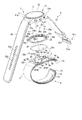
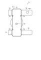
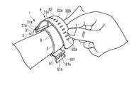
- FIG. 1 is a perspective view showing a configuration of a blood pressure measuring device according to an embodiment of the present invention.
- FIG. 2 is a perspective view showing the configuration of the blood pressure measuring device in an exploded manner.
- FIG. 3 is a side view showing the configuration of the blood pressure measuring device.
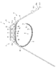
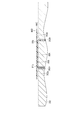
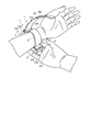
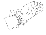
- FIG. 4 is an explanatory view showing a state in which the blood pressure measuring device is worn on the wrist.
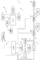
- FIG. 5 is a block diagram showing the configuration of the blood pressure measuring device.
- FIG. 6 is a perspective view showing the configuration of the blood pressure measuring device.
- FIG. 7 is a perspective view showing the configurations of the carla and the cuff structure of the blood pressure measuring device in an exploded manner.
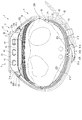
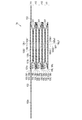
- FIG. 8 is a cross-sectional view showing the configuration of the carla and the cuff unit of the blood pressure measuring device.
- FIG. 9 is a cross-sectional view showing the configuration of the carla and the cuff unit of the blood pressure measuring device.
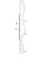
- FIG. 10 is a cross-sectional view showing the configuration of a tension cuff of the blood pressure measuring device.
- FIG. 11 is a cross-sectional view showing the configuration of a tension cuff of the blood pressure measuring device.
- FIG. 12 is a perspective view showing the configuration of Carla of the blood pressure measuring device.
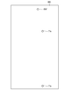
- FIG. 13 is a plan view showing the configuration of the cuff structure of the blood pressure measuring device.
- FIG. 14 is a plan view showing the configuration of the cuff structure.
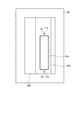
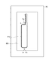
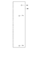
- FIG. 15 is a plan view showing the configuration of the pressing cuff of the blood pressure measuring device.
- FIG. 16 is a cross-sectional view showing the configuration of the pressing cuff.
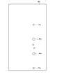
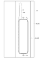
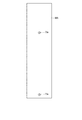
- FIG. 17 is a plan view showing a configuration of a sensing cuff of the blood pressure measuring device.
- FIG. 18 is a cross-sectional view showing the configuration of the sensing cuff.
- FIG. 19 is a plan view showing the configuration of the cuff unit of the blood pressure measuring device.
- FIG. 20 is a plan view showing the configuration of a tension cuff of the blood pressure measuring device.
- FIG. 21 is a cross-sectional view showing the configuration of a tension cuff of the blood pressure measuring device.
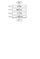
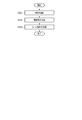
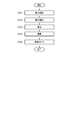
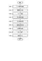
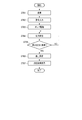
- FIG. 22 is a flow chart showing an example of a method for manufacturing the first structure.
- FIG. 22 is a flow chart showing an example of a method for manufacturing the first structure.
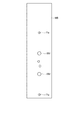
- FIG. 23 is a plan view showing the configuration of the first sheet.
- FIG. 24 is a plan view showing the configuration of the second sheet.
- FIG. 25 is a plan view showing the configuration of the third sheet.
- FIG. 26 is a plan view showing the configuration of the fourth sheet.
- FIG. 27 is an explanatory diagram showing an example of one step of the method for manufacturing the first structure.
- FIG. 28 is an explanatory diagram showing an example of one step of the manufacturing method of the first structure.
- FIG. 29 is an explanatory diagram showing an example of one step of the method for manufacturing the first structure.
- FIG. 30 is an explanatory diagram showing an example of one step of the method for manufacturing the first structure.
- FIG. 31 is an explanatory diagram showing an example of one step of the method for manufacturing the first structure.
- FIG. 32 is an explanatory diagram showing an example of one step of the method for manufacturing the first structure.
- FIG. 33 is an explanatory diagram showing an example of one step of the method for manufacturing the first structure.
- FIG. 34 is a flow chart showing an example of a method for manufacturing the second structure.
- FIG. 35 is a plan view showing the configuration of the fifth sheet.
- FIG. 36 is a plan view showing the configuration of the sixth sheet.
- FIG. 37 is an explanatory diagram showing an example of one step of the method for manufacturing the second structure.
- FIG. 38 is an explanatory diagram showing an example of one step of the method for manufacturing the second structure.
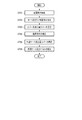
- FIG. 39 is a flow chart showing an example of a method for manufacturing a cuff unit.
- FIG. 40 is a perspective view showing the configuration of the jig.
- FIG. 40 is a perspective view showing the configuration of the jig.
- FIG. 41 is an explanatory diagram showing an example of one step of the manufacturing method of the cuff unit.
- FIG. 42 is an explanatory diagram showing an example of one step of the manufacturing method of the cuff unit.
- FIG. 43 is an explanatory diagram showing an example of one step of the manufacturing method of the cuff unit.
- FIG. 44 is a flow chart showing an example of a method for manufacturing a tension cuff.
- FIG. 45 is a flow chart showing an example of a method for manufacturing the blood pressure measuring device.
- FIG. 46 is a flow chart showing an example of using the blood pressure measuring device.
- FIG. 47 is a perspective view showing an example of wearing the blood pressure measuring device on the wrist.
- FIG. 48 is a perspective view showing an example of wearing the blood pressure measuring device on the wrist.
- FIG. 41 is an explanatory diagram showing an example of one step of the manufacturing method of the cuff unit.
- FIG. 42 is an explanatory diagram showing an example of one step of the manufacturing method of the
- FIG. 49 is a perspective view showing an example of wearing the blood pressure measuring device on the wrist.
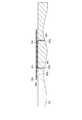
- FIG. 50 is a cross-sectional view schematically showing a state in which the blood pressure measuring device is attached to the wrist.
- FIG. 51 is an explanatory diagram showing a modified example of one step of the manufacturing method of the cuff unit.
- FIG. 52 is a cross-sectional view showing a modified example of the cuff unit and the configuration of the carla.
- FIG. 53 is a cross-sectional view showing another modification of the cuff unit and the configuration of the carla.
- FIG. 1 is a perspective view showing the configuration of the blood pressure measuring device 1 according to the present embodiment.
- FIG. 2 is a perspective view showing the configuration of the blood pressure measuring device 1 in an exploded manner.
- FIG. 3 is a side view showing the configuration of the blood pressure measuring device 1.
- FIG. 4 is an explanatory view showing a state in which the blood pressure measuring device 1 is attached to the wrist 200.
- FIG. 5 is a block diagram showing the configuration of the blood pressure measuring device 1.
- FIG. 6 is a perspective view showing a part of the structure of the blood pressure measuring device 1 omitted.
- FIG. 7 is an exploded perspective view showing the configurations of the carla 5 and the cuff structure 6 of the blood pressure measuring device 1.
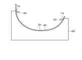
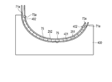
- FIG. 8 is a cross-sectional view showing the configuration of the carla 5 and the cuff unit 250 of the blood pressure measuring device 1.
- FIG. 9 is a cross-sectional view showing the configuration of the carla 5 and the cuff unit 250 of the blood pressure measuring device 1.
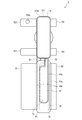
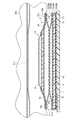
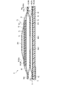
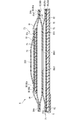
- FIG. 10 is a cross-sectional view showing the configuration of the tension cuff 74 of the blood pressure measuring device 1.
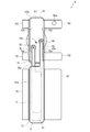
- FIG. 11 is a cross-sectional view showing the configuration of the tension cuff 74 of the blood pressure measuring device 1.
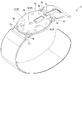
- FIG. 12 is a perspective view showing the configuration of the carla 5 of the blood pressure measuring device 1.
- FIG. 13 is a plan view showing the configuration of the cuff structure 6 of the blood pressure measuring device 1 on the wrist 200 side.
- FIG. 14 is a plan view showing the configuration of the cuff structure 6 on the inner peripheral surface side of the carla 5.
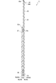
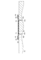
- FIG. 15 is a plan view showing the configuration of the pressing cuff 71 of the blood pressure measuring device 1.
- FIG. 16 is a cross-sectional view showing the configuration of the pressing cuff 71 in a cross section taken along line XVI-XVI in FIG.
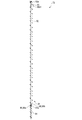
- FIG. 17 is a plan view showing the configuration of the sensing cuff 73 of the blood pressure measuring device 1.
- FIG. 18 is a cross-sectional view showing the configuration of the sensing cuff 73 of the blood pressure measuring device 1 in a cross section taken along line XVIII-XVIII in FIG.
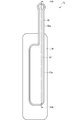
- FIG. 19 is a plan view showing the configuration of the cuff unit 250 of the blood pressure measuring device 1.
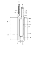
- FIG. 20 is a plan view showing the configuration of the tension cuff 74 of the blood pressure measuring device 1.
- FIG. 21 is a cross-sectional view showing the structure of the tension cuff 74.
- the blood pressure measuring device 1 is an electronic blood pressure measuring device worn on a living body.
- an electronic blood pressure measuring device having an aspect of a wearable device worn on the wrist 200 of a living body will be described.
- the blood pressure measuring device 1 includes a device main body 3, a belt 4 for fixing the device main body 3 to the wrist, a carla 5 arranged between the belt 4 and the wrist, and a pressing cuff 71.
- a cuff structure 6 having a sensing cuff 73 and a tension cuff 74, a fluid circuit 7 for fluidly connecting the device main body 3 and the cuff structure 6, and a power feeding unit 8 provided in the carla 5 are provided. ..
- the apparatus main body 3 includes, for example, a case 11, a display unit 12, an operation unit 13, a pump 14, a flow path unit 15, an on-off valve 16, and a pressure sensor 17.
- a power supply unit 18, a vibration motor 19, and a control board 20 are provided.
- the apparatus main body 3 supplies a fluid to the cuff structure 6 by means of a pump 14, an on-off valve 16, a pressure sensor 17, a control board 20, and the like.
- the case 11 includes a tubular outer case 31, a windshield 32 that covers an opening on the side opposite to the wrist 200 side (outer side) of the outer case 31, and an outer case 31. It includes a base 33 provided on the wrist 200 side inside, a back cover 35 covering the wrist 200 side of the outer case 31, and a seal member 36 provided on the lower surface of the back cover 35.
- the outer case 31 is formed in a cylindrical shape, for example.
- the outer case 31 includes a pair of lugs 31a provided at symmetrical positions in the circumferential direction of the outer peripheral surface, and a spring rod 31b provided between the two pairs of lugs 31a, respectively.
- the windshield 32 is, for example, a circular glass plate.
- the base 33 holds a display unit 12, an operation unit 13, a pump 14, an on-off valve 16, a pressure sensor 17, a power supply unit 18, a vibration motor 19, and a control board 20. Further, the base portion 33 constitutes, for example, a part of the flow path portion 15 that fluidly connects the pump 14 and the cuff structure 6.
- the back cover 35 is configured in an annular shape with the central side open.
- the back cover 35 covers the outer peripheral edge side of the end portion of the outer case 31 on the wrist 200 side.
- the central opening is covered by the carla 5, and together with the carla 5, a back cover that covers the end of the outer case 31 on the wrist 200 side is formed.
- the back cover 35 is fixed to the carla 5 by the four first fastening members 35a, and is fixed to the wrist 200-side end of the outer case 31 by the four second fastening members 35b.
- the back cover 35 is provided at the bottom portion, and is provided at four holes 35c through which the first fastening member 35a fixed to the carla 5 is inserted, and at four locations on the outer peripheral portion protruding in the radial direction. It has four holes 35d through which a second fastening member 35b fixed to the outer case 31 is inserted.
- the first fastening member 35a and the second fastening member 35b are members that mechanically fasten two parts such as screws, bolts, screws, and rivets.
- the first fastening member 35a and the second fastening member 35b are screws.
- the seal member 36 is, for example, a double-sided tape formed in the shape of a region of the back cover 35 in contact with the carla 5.
- the sealing member 36 exists between the carla 5 and the back cover 35 to seal between the carla 5 and the back cover 35.
- the display unit 12 is arranged on the base 33 of the outer case 31 and directly below the windshield 32. As shown in FIG. 5, the display unit 12 is electrically connected to the control board 20.
- the display unit 12 is, for example, a liquid crystal display or an organic electroluminescence display.
- the display unit 12 displays various information including the date and time, blood pressure values such as systolic blood pressure and diastolic blood pressure, and measurement results such as heart rate.
- the operation unit 13 is configured so that commands from the user can be input.
- the operation unit 13 is provided on a plurality of buttons 41 provided in the case 11, a sensor 42 for detecting the operation of the buttons 41, and a display unit 12 or a windshield 32. It includes a touch panel 43.
- the operation unit 13 converts a command into an electric signal by being operated by the user.
- the sensor 42 and the touch panel 43 are electrically connected to the control board 20, and output an electric signal to the control board 20.
- buttons 41 are provided.
- the button 41 is supported by the base 33 and projects from the outer peripheral surface of the outer case 31.
- the plurality of buttons 41 and the plurality of sensors 42 are supported by the base 33.
- the touch panel 43 is provided integrally with the windshield 32, for example.
- the pump 14 is, for example, a piezoelectric pump.
- the pump 14 compresses the air and supplies the compressed air to the cuff structure 6 through the flow path portion 15.
- the pump 14 is electrically connected to the control board 20.
- the flow path portion 15 constitutes a flow path connecting the pump 14 to the pressing cuff 71 and the tension cuff 74, and a flow path connecting the pump 14 to the sensing cuff 73. Further, the flow path portion 15 constitutes a flow path from the pressing cuff 71 and the tension cuff 74 to the atmosphere, and a flow path from the sensing cuff 73 to the atmosphere.
- the flow path portion 15 is an air flow path composed of a hollow portion, a groove, a flow path tank, a tube, and the like provided in the base portion 33 and the like.
- the on-off valve 16 opens and closes a part of the flow path portion 15.
- a plurality of on-off valves 16 are provided as shown in FIG. 5, as a specific example, and the flow path from the pump 14 to the pressing cuff 71 and the tension cuff 74 by the combination of opening and closing of each on-off valve 16 and the pump 14
- the flow path leading to the sensing cuff 73, the flow path connecting the pressing cuff 71 and the tension cuff 74 to the atmosphere, and the flow path connecting the sensing cuff 73 to the atmosphere are selectively opened and closed.
- the four on-off valves 16 are composed of a first on-off valve 16A, a second on-off valve 16B, a third on-off valve 16C, and a fourth on-off valve 16D.
- the first on-off valve 16A opens and closes the flow path connecting the pump 14 and the sensing cuff 73.
- the second on-off valve 16B opens and closes the flow path connecting the pump 14 and the tension cuff 74.
- the second on-off valve 16B and the third on-off valve 16C open and close the flow path connecting the pump 14 and the pressing cuff 71.
- the second on-off valve 16B, the third on-off valve 16C, and the fourth on-off valve 16D open and close the flow path connecting the pump 14 and the atmosphere.
- the pressure sensor 17 detects at least the pressure of the sensing cuff 73.
- the pressure sensor 17 includes, for example, a first pressure sensor 17A and a second pressure sensor 17B.
- the pressure sensor 17 converts the detected pressure into an electric signal and outputs it to the control board 20.
- the first pressure sensor 17A and the second pressure sensor 17B are provided in the flow path connecting the first pressure sensor 17A and the sensing cuff 73 of the flow path portion 15.
- the pressing cuff 71, the sensing cuff 73, the tension cuff 74, and the pump 14 are continuous by opening and closing each on-off valve, so that the pressure in these flow paths is connected to the pump 14, and the pressing cuff 71, the sensing cuff 73.
- the pressure in the internal space of the tension cuff 74 is the pressure in the internal space of the tension cuff 74.
- the pressure of the sensing cuff 73 when the first on-off valve 16A is open and the second on-off valve 16B is closed in other words, the flow connecting the pump 14 and the sensing cuff 73.
- the pressure of the road portion 15 is detected.
- the pressure of the sensing cuff 73 and the tension cuff 74 in other words, The pressure of the flow path portion 15 connecting the pump 14, the sensing cuff 73 and the tension cuff 74 is detected.
- the pressure sensor 17 has a pressing cuff 71, sensing when the first on-off valve 16A, the second on-off valve 16B and the third on-off valve 16C are open and the fourth on-off valve 16D is open or closed.
- the pressure of the cuff 73 and the tension cuff 74 in other words, the pressure of the flow path portion 15 connecting the pump 14, the pressing cuff 71, the sensing cuff 73 and the tension cuff 74 is detected.
- the power supply unit 18 is a secondary battery such as a lithium ion battery, for example.
- the power supply unit 18 is electrically connected to the control board 20 as shown in FIG.
- the power supply unit 18 supplies power to the control board 20.
- the control board 20 includes, for example, a board 51, an acceleration sensor 52, a communication unit 53, a storage unit 54, and a control unit 55.
- the control board 20 is composed of an acceleration sensor 52, a communication unit 53, a storage unit 54, and a control unit 55 mounted on the board 51.
- the substrate 51 is fixed to the base 33 of the case 11 with screws or the like.
- the acceleration sensor 52 is, for example, a 3-axis acceleration sensor.
- the acceleration sensor 52 outputs an acceleration signal representing acceleration in three directions orthogonal to each other of the device main body 3 to the control unit 55.
- the acceleration sensor 52 is used to measure the amount of activity of a living body equipped with the blood pressure measuring device 1 from the detected acceleration.
- the communication unit 53 is configured to be able to transmit and receive information wirelessly or by wire with an external device.
- the communication unit 53 transmits information controlled by the control unit 55 and information such as the measured blood pressure value and pulse to an external device via the network, and software from the external device via the network. Receives the update program, etc. and sends it to the control unit.
- the network is, for example, the Internet, but is not limited to this, and may be a network such as a LAN (Local Area Network) provided in the hospital, or a predetermined standard such as USB. It may be direct communication with an external device using a cable having a terminal or the like. Therefore, the communication unit 53 may be configured to include a plurality of wireless antennas, micro USB connectors, and the like.
- LAN Local Area Network
- USB Universal Serial Bus
- the storage unit 54 contains program data for controlling the entire blood pressure measuring device 1 and the fluid circuit 7, setting data for setting various functions of the blood pressure measuring device 1, and a blood pressure value and pulse from the pressure measured by the pressure sensor 17.
- the calculated data and the like for calculating the above are stored in advance.
- the storage unit 54 stores information such as the measured blood pressure value and pulse.
- the control unit 55 is composed of a single CPU or a plurality of CPUs, and controls the operation of the entire blood pressure measuring device 1 and the operation of the fluid circuit 7.
- the control unit 55 is electrically connected to the display unit 12, the operation unit 13, the pump 14, each on-off valve 16 and each pressure sensor 17, and supplies electric power. Further, the control unit 55 controls the operations of the display unit 12, the pump 14, and the on-off valve 16 based on the electric signals output by the operation unit 13 and the pressure sensor 17.
- the control unit 55 has a main CPU (Central Processing Unit) 56 that controls the operation of the entire blood pressure measuring device 1 and a sub CPU 57 that controls the operation of the fluid circuit 7.
- the main CPU 56 obtains a measurement result such as a blood pressure value such as systolic blood pressure and diastolic blood pressure and a heart rate from an electric signal output by the pressure sensor 17, and outputs an image signal corresponding to the measurement result to the display unit 12. .
- a measurement result such as a blood pressure value such as systolic blood pressure and diastolic blood pressure and a heart rate
- the sub CPU 57 drives the pump 14 and the on-off valve 16 to send compressed air to the pressing cuff 71 and the sensing cuff 73. Further, the sub CPU 57 controls the drive and stop of the pump 14 and the opening and closing of the on-off valve 16 based on the electric signal output from the pressure sensor 17. By controlling the pump 14 and the on-off valve 16, the sub CPU 57 selectively sends compressed air to the pressing cuff 71 and the sensing cuff 73, and selectively depressurizes the pressing cuff 71 and the sensing cuff 73.
- the belt 4 includes a first belt 61 provided on one pair of lugs 31a and a spring rod 31b, and a second belt 61 provided on the other pair of lugs 31a and a spring rod 31b.
- a belt 62 is provided. The belt 4 is wrapped around the wrist 200 via the carla 5.
- the first belt 61 is a so-called parent and is configured in a band shape that can be connected to the second belt 62. As shown in FIGS. 1 to 3, the first belt 61 has a belt portion 61a and a buckle 61b. The belt portion 61a is formed in a band shape. The belt portion 61a is made of an elastically deformable resin material. Further, the belt portion 61a has a flexible sheet-like insert member inside which expansion and contraction of the belt portion 61a in the longitudinal direction is suppressed. The belt portion 61a is formed at one end and has a first hole 61c orthogonal to the longitudinal direction of the belt 61a and a second hole 61c formed at the other end and orthogonal to the longitudinal direction of the first belt 61. It has 61d.
- the first hole portion 61c is provided at the end portion of the belt portion 61a.
- the first hole portion 61c has an inner diameter into which the spring rod 31b can be inserted and the first belt 61 can rotate with respect to the spring rod 31b. That is, the first belt 61 is rotatably held in the outer case 31 between the pair of lugs 31a and by arranging the first hole portion 61c in the spring rod 31b.
- the second hole portion 61d is provided at the tip of the belt portion 61a.
- a buckle 61b is attached to the second hole 61d.
- the buckle 61b has a rectangular frame-shaped frame-shaped body 61e and a stick 61f rotatably attached to the frame-shaped body 61e.
- One side of the frame-shaped body 61e to which the sticking rod 61f is attached is inserted into the second hole portion 61d, and the frame-shaped body 61e is rotatably attached with respect to the belt portion 61a.
- the second belt 62 is a so-called sword tip, and is formed in a band shape having a width that can be inserted into the frame-shaped body 61e.
- the second belt 62 is made of an elastically deformable resin material. Further, the second belt 62 has a sheet-like insert member inside which is flexible and suppresses expansion and contraction of the second belt 62 in the longitudinal direction.
- the second belt 62 has a plurality of small holes 62a into which the stick 61f is inserted. Further, the second belt 62 is provided at one end and has a third hole portion 62b orthogonal to the longitudinal direction of the second belt 62. The third hole portion 62b has an inner diameter into which the spring rod 31b can be inserted and the second belt 62 can rotate with respect to the spring rod 31b. That is, the second belt 62 is rotatably held in the outer case 31 between the pair of lugs 31a and by arranging the third hole portion 62b in the spring rod 31b.
- the second belt 62 is inserted into the frame-shaped body 61e, and the rod 61f attached to the small hole 62a is inserted, so that the first belt 61 and the second belt 62 are integrally connected to the outer shell. Together with the case 31, it forms an annular shape that follows the circumferential direction of the wrist 200.
- the belt 4 forms an annular shape that follows the circumferential direction of the wrist 200, thereby pressing the carla 5 and elastically deforming the carla 5 so as to follow the circumferential direction of the wrist of the wearer of the blood pressure measuring device 1.
- the carla 5 is formed in a band shape that curves along the circumferential direction of the wrist 200.
- the carla 5 is formed so that one end and the other end are separated from each other.
- the outer surface of the carla 5 on one end side is fixed to the back cover 35 of the apparatus main body 3.
- the carla 5 is arranged at a position where one end and the other end protrude toward one side of the wrist 200 with respect to the back cover 35.
- one end and the other end of the carla 5 are arranged on the side of the wrist 200.
- one end and the other end of the carla 5 are adjacent to each other at a predetermined distance.
- the carla 5 is made of, for example, a resin material.
- the carla 5 is formed of polypropylene to a thickness of about 1 mm.
- the carla 5 is configured in a band shape that curves along the circumferential direction of the wrist. Further, the carla 5 is provided at a position facing the back side of the wrist 200 on one end side, and is provided around the disc-shaped cover portion 5a and the cover portion 5a forming the back cover together with the back cover 35. It has a relief portion 5b that can move the second fastening member 35b that fixes the outer case 31 and the back cover 35.
- the cover portion 5a and a portion adjacent thereto are formed in a flat plate shape, and one end side and the other end side of the cover portion 5a are curved with a predetermined curvature.
- the carla 5 is formed so that the length from the cover portion 5a to one end is shorter than the length from the cover portion 5a to the other end.
- the short side from the cover portion 5a to one end is arranged on the back side of the wrist, and the longitudinal side from the cover portion 5a to the other end is one side from the back side of the wrist. It extends through to the palm side of the wrist 200.
- the carla 5 is formed in a shape in which the other end is located on the inner peripheral surface side of one end side when one end and the other end are close to each other.
- the width of the wrist 200 of the carla 5 in the width direction is set to be larger on the back side of the wrist 200 of the carla 5 than on the palm side of the wrist 200 of the carla 5.
- the radius of curvature of one end of the back side of the wrist 200 of the wrist 200 is set to be larger than the radius of curvature of the other end of the palm side of the wrist 200.
- the carla 5 is provided adjacent to the cover portion 5a on a part of the cover portion 5a, an outer surface on one end side from the cover portion 5a, and more specifically, an outer surface on the short side extending from the cover portion 5a.
- a recess 5c is provided.
- the cover portion 5a includes the inserted reinforcing insert member 5d.
- the cover portion 5a is fixed to the wrist 200 side of the outer case 31 via the fixed back cover 35.
- the cover portion 5a is provided at a position facing the four hole portions 35c of the back cover 35, and has a screw hole 5e into which the first fastening member 35a for fixing the back cover 35 is screwed. Further, the cover portion 5a has three hole portions 5f for connecting the cuff structure 6 to the apparatus main body 3.
- the relief portion 5b covers the second fastening member 35b without the second fastening member 35b interfering with the carla 5. It is a relief for arranging the tool 35 and for arranging the tool for rotating the second fastening member 35b.
- the three hole portions 5f have a first hole portion 5f1 formed to have an inner diameter into which the connection portion 84 described later in the pressing cuff 71 can be inserted, and a first hole portion 5f1 formed into an inner diameter into which the connecting portion 93 described later in the sensing cuff 73 can be inserted.
- the two-hole portion 5f2 and the third-hole portion 5f3 formed with an inner diameter into which the connection portion 103 described later of the tension cuff 74 can be inserted.
- the second hole portion 5f2 is arranged on the other end side of the palm side of the carla 5 in the cover portion 5a with respect to the first hole portion 5f1 and the third hole portion 5f3.
- Such a carla 5 is fixed to the outer case 31 with one end and the other end facing the second belt 62 of the belt 4. Further, the carla 5 has a cuff structure 6 facing the palm side of the wrist 200 by at least a position facing the palm side of the wrist 200 curved along the circumferential direction along the palm side of the wrist 200. , Hold in a curved state following the shape of the palm side of the wrist 200.
- the carla 5 has a hardness having flexibility and shape retention.
- flexibility means that the shape is deformed in the radial direction when an external force of the belt 4 is applied to the carla 5.
- flexibility means that when the carla 5 is pressed by the belt 4, the shape of the side view is deformed so as to be close to the wrist, follow the shape of the wrist, or follow the shape of the wrist.
- the shape retention means that the carla 5 can maintain a preformed shape when no external force is applied.
- the shape retention means that in the present embodiment, the shape of the carla 5 can be maintained in a curved shape along the circumferential direction of the wrist.
- the cuff structure 6 is arranged on the inner peripheral surface, and the cuff structure 6 is held along the shape of the inner peripheral surface of the carla 5.
- the pressing cuff 71 and the tension cuff 74 are arranged on the inner peripheral surface, and the cuff structure 6 is fixed by the bonding layer 75 provided between the carla 5 and the pressing cuff 71 and the tension cuff 74. By doing so, the cuff structure 6 is held.
- the bonding layer 75 is an adhesive or double-sided tape.
- the cuff structure 6 includes a pressing cuff 71, a back plate 72, a sensing cuff 73, and a tension cuff 74. Further, the cuff structure 6 includes a bonding layer 75 that joins each structure and the carla 5 and the cuffs 71 and 74. The cuff structure 6 is fixed to the carla 5. In the cuff structure 6, the pressing cuff 71, the back plate 72 and the sensing cuff 73 are laminated and arranged on the carla 5, and the tension cuff 74 is arranged on the carla 5 apart from the pressing cuff 71, the back plate 72 and the sensing cuff 73. Will be done.
- the cuff structure 6 has a pressing cuff 71 and a back on the inner peripheral surface of the wrist 200 of the carla 5 on the palm side, from the inner peripheral surface of the carla 5 toward the wrist 200.
- the plate 72 and the sensing cuff 73 are laminated and fixed in this order.
- the tension cuff 74 is arranged on the inner peripheral surface of the wrist 200 of the carla 5 on the back side of the hand.
- Each member of the cuff structure 6 is fixed to a member adjacent in the stacking direction by a joint layer 75.
- the pressing cuff 71 is fluidly connected to the pump 14 via the flow path portion 15.
- the pressing cuff 71 expands to press the back plate 72 and the sensing cuff 73 toward the wrist 200 side.
- the pressing cuff 71 is attached to a plurality of, for example, a two-layer air bag (first bag-shaped structure) 81 and an air bag 81 facing the carla 5.
- the jointed portion 82 provided, the flow path body 83 communicating with the air bag 81, and the connecting portion 84 provided at the tip of the flow path body 83 are included.
- Such a pressing cuff 71 is configured by integrally welding a plurality of sheet members 86.
- the air bag 81 is a bag-shaped structure, and in the present embodiment, the blood pressure measuring device 1 has a configuration in which air is used by the pump 14, and thus the air bag will be used for description.
- the bag-shaped structure may be a fluid bag that expands with the fluid.
- the plurality of air bags 81 are laminated and fluidly communicate with each other in the stacking direction.
- the air bag 81 is formed in a rectangular bag shape that is long in one direction. Further, the width of the air bag 81 in the lateral direction is set to be the same as the width of the carla 5 in the lateral direction.
- the air bag 81 is formed by, for example, combining two sheet members 86 and heat-welding them in a rectangular frame shape long in one direction as shown in FIGS. 8, 9, 13 to 17, as shown by the welding portion 81a. It is composed. Further, in the two-layer air bag 81, the two air bags 81 are welded by heat and combined integrally, or the air bags 81 are welded after welding the opposing sheet members 86 of the adjacent air bags 81. It is composed by forming.
- the two-layer air bags 81 are fluidly continuous by openings provided in the sheet members 86 facing each other. Further, in the two-layer air bag 81, the opposing sheet members 86 are bridge-welded to each other in a four-sided frame shape smaller than the welding portion 81a located on the outer peripheral edge, and the bridge welding portion 81b surrounds a plurality of openings. Adjacent air bags 81 are integrally formed and fluidly continuous inside the bridge welded portion 81b.
- the bridge welding and the bridge of the bridge welding portion mean that the adjacent air bags 81 are integrally joined.
- a single or a plurality of jointed portions 82 are provided on at least a part of the edge portion of the air bag 81 arranged adjacent to the carla 5.
- the jointed portion 82 is formed by a part of the sheet member 86 constituting the air bag 81.
- one joint portion 82 is provided on each of the lateral edges of the air bag 81.
- the jointed portion 82 may be divided in the longitudinal direction of the air bag 81 by a slit, or may be provided in plurality in the longitudinal direction of the air bag 81.
- the jointed portion 82 is joined to at least the outer peripheral surface of the carla 5 when the pressing cuff 71 is arranged on the inner peripheral surface of the carla 5.
- the two joints 82 are laminated and welded together.
- the two jointed portions 82 are set to, for example, different lengths in the lateral direction of the air bag 81.
- the two joints 82 are laminated and welded on one end side of the carla 5 in the lateral direction.
- the length of the two jointed portions 82 can be appropriately set as long as the tips can be arranged on the outer peripheral surface of the carla 5, and the two joint portions 82 may or may not be laminated, but can be laminated. When set to a value, it is preferable that the tip does not extend outward from the outer edge of the outer peripheral surface of the carla 5.
- the flow path body 83 is integrally provided at one end of one air bag 81, for example, an air bag 81 adjacent to the carla 5 in the longitudinal direction. Be done.
- the flow path body 83 is provided at the end of the air bag 81 near the device main body 3.
- the flow path body 83 is formed in a width smaller than the width in the lateral direction of the air bag 81 and is formed in a long shape in one direction, and the tip is formed in a circular shape.
- the flow path body 83 has a connecting portion 84 at the tip thereof.
- the flow path body 83 is connected to the flow path portion 15 via the connection portion 84, and constitutes a flow path between the flow path portion 15 of the apparatus main body 3 and the air bag 81.
- a part of the sheet member 86 adjacent to the region constituting the air bag 81 of the sheet member 86 is formed into a long frame shape in one direction. It is composed of welding by heat.
- Such a flow path body 83 is arranged between the inner peripheral surface of the carla 5 and the tension cuff 74, and the tip thereof is the main surface on the wrist 200 side of the region where the cover portion 5a of the carla 5 is provided. , Is arranged at a position facing the first hole portion 5f1.
- the air bag 81 provided with the flow path body 83, a part of the welding portion 81a for welding the two sheet members 86 in a rectangular frame shape is non-welded, and the air bag 81 is continuous with the welding portion 83a constituting the flow path body 83.
- the air bag 81 is fluidly continuous with the flow path body 83.
- connection portion 84 is, for example, a nipple.
- the connecting portion 84 is provided at the tip of the flow path body 83.
- the tip of the connecting portion 84 is exposed from the seat member 86 facing the carla 5 among the two seat members 86 constituting the flow path body 83.
- the connecting portion 84 is inserted into the first hole portion 5f1 of the cover portion 5a and connected to the flow path portion 15.
- the pressing cuff 71 having such a configuration has the first sheet member 86a, the first sheet member 86a, and the first layer of air from the wrist 200 side, as shown in FIGS. 8, 9, and 52.
- the second sheet member 86b constituting the bag 81 and the second sheet member 86b are integrally joined, and the third sheet member 86c forming the bonded portion 82, the third sheet member 86c, and the second layer of air are joined.
- a fourth sheet member 86d constituting the bag 81 and the flow path body 83 is provided.
- the pressing cuff 71 is integrally formed by joining adjacent sheet members 86 by heat welding.
- the first sheet member 86a and the second sheet member 86b are formed in the same rectangular shape as the air bag 81, and the peripheral edges of the four sides are welded to form the air bag 81.
- the second seat member 86b and the third seat member 86c are arranged so as to face each other, and have a plurality of openings 86b1 and 86c1 that fluidly connect the two air bags 81, respectively.
- the second sheet member 86b and the third sheet member 86c are integrally bridge-welded around the plurality of openings 86b1 and 86c1 in a four-sided frame shape smaller than the four sides to which the air bag 81 is welded by heat. Be joined.
- the third sheet member 86c is formed in a shape capable of forming, for example, the air bag 81, the jointed portion 82, and the flow path body 83.
- the fourth sheet member 86d is configured, for example, in a shape capable of forming the air bag 81 and the flow path body 83. Further, the fourth sheet member 86d has, for example, a hole 86d1 into which the tip of the connecting portion 84 can be inserted.
- the third sheet member 86c and the fourth sheet member 86d are arranged so as to face each other, and along the peripheral shape of the air bag 81 and the flow path body 83 so that the air bag 81 and the flow path body 83 are fluidly continuous.
- the air bag 81, the bonded portion 82, and the flow path body 83 are formed by being welded by heat and cut into a predetermined shape.
- connection portion 84 is arranged in the hole portion 86d1 of the fourth sheet member 86d, and the periphery of the hole portion 86d1 is welded to the connection portion 84 by heat. Further, the fourth sheet member 86d is joined to the inner peripheral surface of the carla 5, and the bonded portion 82 of the third sheet member 86c is joined to the outer peripheral surface of the carla 5 via the joining layer 75.
- the back plate 72 is attached to the outer surface of the first sheet member 86a of the pressing cuff 71 by the joining layer 75.
- the back plate 72 is made of a resin material and is formed in a plate shape.
- the back plate 72 is made of polypropylene, for example, and is formed in a plate shape having a thickness of about 1 mm.
- the back plate 72 has shape followability.
- the shape followability means a function in which the back plate 72 can be deformed so as to imitate the shape of the contacted portion of the wrist 200 to be arranged, and the back plate 72 faces the contacted portion of the wrist 200.
- the contact here includes both direct contact and indirect contact via the sensing cuff 73.
- the back plate 72 has a plurality of grooves 72a extending in a direction orthogonal to the longitudinal direction on both main surfaces thereof.
- the plurality of grooves 72a face each other in the thickness direction of the back plate 72. Further, the plurality of grooves 72a are arranged at equal intervals in the longitudinal direction of the back plate 72.
- the back plate 72 Since the portion of the back plate 72 having the plurality of grooves 72a is thinner than the portion having the plurality of grooves 72a, the portion having the plurality of grooves 72a is easily deformed. Therefore, the back plate 72 follows the shape of the wrist 200. It deforms and has a shape-following property that extends in the circumferential direction of the wrist.
- the back plate 72 is formed to have a length that covers the palm side of the wrist 200.
- the back plate 72 transmits the pressing force from the pressing cuff 71 to the main surface of the sensing cuff 73 on the back plate 72 side while following the shape of the wrist 200.
- the sensing cuff 73 is fluidly connected to the pump 14 via the flow path portion 15.
- the sensing cuff 73 is fixed to the main surface of the back plate 72 on the wrist 200 side. As shown in FIGS. 4 and 52, the sensing cuff 73 comes into direct contact, for example, with the region of the wrist 200 where the artery 210 resides.
- the artery 210 is a radial artery and an ulnar artery.
- the sensing cuff 73 is formed in the same shape as the back plate 72 or smaller than the back plate 72 in the longitudinal direction and the width direction of the back plate 72.
- the sensing cuff 73 expands to compress the area of the wrist 200 on the palm side of the artery 210.
- the sensing cuff 73 is pressed toward the wrist 200 side via the back plate 72 by the expanded pressing cuff 71.
- the sensing cuff 73 includes one air bag (second bag-shaped structure) 91 and the air bag 91, as shown in FIGS. 8, 9, 13, 14, 17, and 18. It includes a flow path body 92 that communicates with the flow path body 92, a connecting portion 93 provided at the tip of the flow path body 92, and a joining allowance 94 that is at least partially joined to the pressing cuff 71.
- one main surface of the air bag 91 is fixed to the back plate 72.
- the sensing cuff 73 is joined to the main surface of the back plate 72 on the wrist 200 side by the joining layer 75.
- Such a sensing cuff 73 is configured by integrally welding two sheet members 96.
- the air bag 91 is a bag-shaped structure, and in the present embodiment, the blood pressure measuring device 1 has a configuration in which air is used by the pump 14, and thus the air bag will be used for description.
- the bag-shaped structure may be a liquid bag or the like.
- the air bag 91 is formed in a rectangular shape that is long in one direction.
- the air bag 91 is formed into a rectangular frame that is long in one direction, for example, by combining two sheet members 96 and showing the welded portion 91a in FIGS. 8, 9, 13, 14, 17, and 18. It is composed of welding by heat.
- the flow path body 92 is integrally provided on a part of the edge portion at one end in the longitudinal direction of the air bag 91.
- the flow path body 92 is provided at the end of the air bag 91 near the device main body 3.
- the flow path body 92 is formed in a width smaller than the width in the lateral direction of the air bag 91 and is formed in a long shape in one direction, and the tip is formed in a circular shape.
- the flow path body 92 has a connecting portion 93 at the tip thereof.
- the flow path body 92 has a connecting portion 93 at the tip thereof.
- the flow path body 92 is connected to the flow path portion 15 via the connection portion 93, and constitutes a flow path between the flow path portion 15 of the apparatus main body 3 and the air bag 91.
- a part of the sheet member 96 adjacent to the region constituting the air bag 91 of the sheet member 96 is formed into a long frame shape in one direction. It is composed of welding by heat.
- the air bag 91 has a structure in which a part of the welding portion 91a for welding the two sheet members 96 in a rectangular frame shape is non-welded and is continuous with the welding portion 92a constituting the flow path body 92.
- the air bag 91 and the flow path body 92 are fluidly continuous.
- Such a flow path body 92 is arranged between the inner peripheral surface of the carla 5 and the tension cuff 74, and the tip thereof is the main surface on the wrist 200 side of the region where the cover portion 5a of the carla 5 is provided. , Is arranged at a position facing the second hole portion 5f2.
- connection portion 93 is, for example, a nipple.
- the connecting portion 93 is provided at the tip of the flow path body 92. Further, the tip of the connecting portion 93 is exposed to the outside from the seat member 96 facing the carla 5 and the back plate 72 among the two seat members 96 constituting the flow path body 92.
- the connecting portion 93 is inserted into the second hole portion 5f2 of the cover portion 5a and connected to the flow path portion 15.
- the joining allowance 94 can be joined to the air bag 81 adjacent to the air bag 91 among the plurality of air bags 81 of the pressing cuff 71, in other words, to a part of the welded portion 81a of the air bag 81 on the back plate 72 side by welding. It is formed, and as a specific example, it is joined to an outer edge portion along the longitudinal direction of the air bag 81 on the back plate 72 side.
- the outer edge of the air bag 81 is a region around the outer edge of the air bag 81.
- the air bag 81 is configured by welding two sheet members 86, the welded portion 81a is an example of the outer edge portion of the air bag 81.
- the joining allowance 94 is formed continuously and integrally with, for example, a welded portion 91a of the air bag 91 and a part of the welded portion 92a of the flow path body 92. Therefore, a part of the joint allowance 94 is formed at the outer edge portion along the longitudinal direction of the air bag 91.
- the joining allowance 94 is, for example, a region of the two sheet members 96 that constitutes the air bag 91 and a region that is adjacent to the region that constitutes the flow path body 92, and the air bag 81 on the back plate 72 side of the pressing cuff 71. It is formed by forming the same shape as the welded portion 81a.
- the outer edge portion of the joint allowance 94 is formed to have the same shape as the welded portion 81a of the air bag 81 on the back plate 72 side of the pressing cuff 71.
- the portion facing the welding portion 81a along the longitudinal direction of the air bag 81 constitutes the bonding portion 94a to be welded to the welding portion 81a.
- the joint portion 94a is joined to the pressing cuff 71 by welding.
- the two outer edge portions of the joining allowance 94 along the longitudinal direction of the air bag 91 of the sensing cuff 73 are joined from one end to the other end of the welded portion 81a along the longitudinal direction of the air bag 81.
- the outer edge portion of the joining allowance 94 along the lateral direction is not joined to the welded portion 81a along the lateral direction of the air bag 81.
- the sensing cuff 73 having such a configuration includes a fifth seat member 96a and a sixth seat member 96b from the wrist 200 side, as shown in FIGS. 8 and 9.
- the sensing cuff 73 is configured by joining adjacent sheet members 96 by heat welding.
- the fifth sheet member 96a and the sixth sheet member 96b are configured in a shape capable of forming the air bag 91, the flow path body 92, and the joining allowance 94.
- the fifth sheet member 96a and the sixth sheet member 96b are arranged so as to face each other, and along the peripheral shape of the air bag 91 and the flow path body 92 so that the air bag 91 and the flow path body 92 are fluidly continuous.
- the air bag 91, the flow path body 92, and the bonding allowance 94 are formed by being welded by heat and cut into a predetermined shape.
- the sixth sheet member 96b has, for example, a hole 96b1 into which the tip of the connecting portion 93 can be inserted.
- the connection portion 93 is arranged in the hole portion 96b1, and the periphery of the hole portion 96b1 is welded to the connection portion 93 by heat.
- the sixth sheet member 96b is joined to the inner peripheral surface of the back plate 72 via the joining layer 75.
- the pressing cuff 71 and the sensing cuff 73 are fixed, and the back plate 72 is fixed to the pressing cuff 71 and the sensing cuff 73.
- the cuff unit 250 is manufactured by using a jig 400 having a mounting surface 401 having a curved surface, which will be described later, so that the pressing cuff 71 of the carla 5 is joined in a state before being joined to the carla 5. It is constructed in a curved shape that follows the surface of the surface.
- the tension cuff 74 is fluidly connected to the pump 14 via the flow path portion 15. As shown in FIG. 4, the tension cuff 74 pulls the belt 4 and the carla 5 toward the back side of the wrist 200 by pressing the carla 5 so as to be separated from the wrist 200 by expanding. As shown in FIGS. 10, 11, 20, and 21, the tension cuff 74 includes a plurality of, for example, six-layer air bags 101 and a joint portion 102 provided on the air bag 101 facing the carla 5. , A connecting portion 103 provided in the air bag 101 facing the carla 5, and at least a notch 104 provided in the air bag 101 facing the carla 5. Such a tension cuff 74 is configured by integrally welding a plurality of sheet members 106.
- the tension cuff 74 is fixed to the area where the flow path bodies 83 and 92 are provided and to the back side of the wrist 200 of the carla 5 including the cover portion 5a. That is, the flow path body 83 of the pressing cuff 71 and the flow path body 92 of the sensing cuff 73 are arranged between the back side of the wrist 200 of the carla 5 and the tension cuff 74.
- the tension cuff 74 has the thickness at the time of expansion in the expansion direction, in the present embodiment, in the direction opposite to the carla 5 and the wrist 200, the thickness at the time of expansion of the pressing cuff 71 in the expansion direction, and sensing.
- the cuff 73 is thicker than the thickness at the time of expansion in the expansion direction. That is, the air bag 101 of the tension cuff 74 has a layer structure larger than that of the air bag 81 of the pressing cuff 71 and the air bag 91 of the sensing cuff 73, and the thickness when expanded from the carla 5 toward the wrist 200 is increased. It is thicker than the pressing cuff 71 and the sensing cuff 73.
- the tension cuff 74 including the six-layer air bag 101 is attached to the first outer layer 111 and the first outer layer 111 composed of one air bag 101, as shown in FIGS. 10, 11 and 20.
- a second intermediate layer 113 to be formed and a second outer layer 114 composed of one air bag 101 fused and integrally combined with the second intermediate layer 113 by heat are provided.
- the air bag 101 is a bag-shaped structure, and in the present embodiment, the blood pressure measuring device 1 has a configuration in which air is used by the pump 14, and thus the air bag will be used for description.
- the bag-shaped structure may be a fluid bag that expands with the fluid.
- the plurality of air bags 101 are laminated and fluidly communicate with each other in the stacking direction.
- the air bag 101 is formed in a rectangular bag shape that is long in one direction. Further, the width of the air bag 101 in the lateral direction is set to be the same as the width of the carla 5 in the lateral direction.
- the air bag 101 is formed into a rectangular frame that is long in one direction, for example, by combining two sheet members 106 and showing the welded portion 101a in FIGS. 10, 11, 13, 14, 20, and 21. It is composed of welding by heat.
- the six-layer air bags 101 are fluidly continuous by openings provided in the sheet members 106 facing each other.
- the six-layer air bag 101 is a sheet in which the first outer layer 111 and the first intermediate layer 112, the first intermediate layer 112 and the second intermediate layer 113, and the second intermediate layer 113 and the second outer layer 114 face each other.
- the members 106 are bridge-welded to each other in a four-sided frame shape smaller than the welding portion 81a located on the outer peripheral edge, and the bridge welding portions 101b surround a plurality of openings to integrally form adjacent air bags 101. It is fluidly continuous inside the bridge welding portion 101b.
- the first outer layer 111 is formed by one air bag 101 arranged on the wrist 200 side.
- the first outer layer 111 constitutes the first layer air bag 101 from the wrist 200 side of the six layers air bag 101.
- the first intermediate layer 112 is laminated on the first outer layer 111.
- the first intermediate layer 112 is formed by a two-layer air bag 101.
- the first intermediate layer 112 constitutes the second layer and the third layer air bag 101 from the wrist 200 side among the six layers of air bag 101.
- the first intermediate layer 112 is configured by integrally welding two layers of air bags 101 at the outer peripheral edge. In other words, the first intermediate layer 112 is formed by integrally welding four sheet members 106 in the shape of the outer peripheral edge of the air bag 101.
- the second intermediate layer 113 is laminated on the first intermediate layer 112.
- the second intermediate layer 113 is formed by a two-layer air bag 101.
- the second intermediate layer 113 constitutes the fourth layer and the fifth layer of the air bag 101 from the wrist 200 side among the six layers of the air bag 101.
- the second intermediate layer 113 is formed by integrally welding the two layers of air bags 101 at the outer peripheral edge. In other words, the second intermediate layer 113 is formed by integrally welding the four sheet members 106 in the shape of the outer peripheral edge of the air bag 101.
- the second outer layer 114 is formed by one air bag 101 arranged on the carla 5 side.
- the second outer layer 114 constitutes the sixth layer air bag 101 from the wrist 200 side of the six layers air bag 101.
- a single or a plurality of jointed portions 102 are provided on at least a part of the edge portion of the air bag 101 arranged adjacent to the carla 5.
- the jointed portion 102 is formed by a part of the sheet member 106 constituting the air bag 101.
- jointed portions 102 will be provided on each of the lateral edges of the air bag 101 in the longitudinal direction of the air bag 101.
- the jointed portion 102 is provided in the air bag 101 while avoiding a position facing the cover portion 5a of the carla 5.
- the jointed portion 102 has a relief portion 102a for exposing the feeding terminal 8b to the outside at a portion of the feeding portion 8 provided on the carla 5 facing the feeding terminal 8b described later.
- the relief portion 102a is, for example, an opening capable of exposing the power feeding terminal 8b to the outside, and has a circular shape as an example.
- the jointed portion 102 is joined to at least the outer peripheral surface of the carla 5 when the tension cuff 74 is arranged on the inner peripheral surface of the carla 5. Further, the jointed portions 102 arranged at the same position in the lateral direction of the air bag 101 are laminated and welded.
- the two jointed portions 102 are set to, for example, different lengths in the lateral direction of the air bag 101.
- the two joints 102 are laminated and welded on one end side of the carla 5 in the lateral direction.
- the length of the two bonded portions 102 can be appropriately set as long as the tips can be arranged on the outer peripheral surface of the carla 5, and the two joint portions 102 may or may not be laminated, but can be laminated. When set to a value, it is preferable that the tip does not extend outward from the outer edge of the outer peripheral surface of the carla 5.
- connection portion 103 is, for example, a nipple.
- the connecting portion 103 is provided at a position on the central side in the longitudinal direction of the air bag 101 arranged adjacent to the carla 5 and facing the third hole portion 5f3 of the cover portion 5a.
- the tip of the connecting portion 103 is exposed from the seat member 106 facing the carla 5 among the two seat members 106 constituting the air bag 101.
- the connecting portion 103 is inserted into the third hole portion 5f3 of the cover portion 5a and connected to the flow path portion 15.
- the notch portion 104 is provided at a position facing the relief portion 5b provided on the carla 5.
- the cutout portion 104 is provided in the air bag 101 of the sixth layer forming the second outer layer 114.
- the tension cuff 74 has a seventh seat member 106a, an eighth seat member 106b, a ninth seat member 106c, and a tenth seat member 106c from the wrist 200 side.
- Sheet member 106d, 11th sheet member 106e, 12th sheet member 106f, 13th sheet member 106g, 14th sheet member 106h, 15th sheet member 106i, 16th sheet member 106j, 17th sheet A member 106k and an 18th sheet member 106l are provided.
- the tension cuff 74 is integrally formed by joining adjacent sheet members 106 by heat welding.
- the 7th sheet member 106a to the 18th sheet member 106l are formed in the same rectangular shape as the air bag 101.
- the seventh sheet member 106a and the eighth sheet member 106b are welded by heat along the shape of the peripheral edges of the four sides of the air bag 101 to form the first air bag 101 from the wrist 200 side. That is, the 7th sheet member 106a and the 8th sheet member 106b form the first outer layer 111.
- the eighth sheet member 106b and the ninth sheet member 106c are arranged so as to face each other, and have a plurality of openings 106b1 and 106c1 that fluidly connect the two air bags 101, respectively. Further, the eighth sheet member 106b and the ninth sheet member 106c are integrally bridge-welded around the plurality of openings 106b1 and 106c1 in a four-sided frame shape smaller than the four sides to which the air bag 101 is welded by heat. Be joined.
- the 9th sheet member 106c and the 10th sheet member 106d are welded by heat along the shape of the peripheral edges of the four sides of the air bag 101 to form the second layer air bag 101 from the wrist 200 side.
- the tenth sheet member 106d and the eleventh sheet member 106e are arranged to face each other as shown in FIGS. 10 and 11 and 20, respectively, and a plurality of openings 106d1 that fluidly connect the two air bags 101. It has 106e1.
- the eleventh sheet member 106e and the twelfth sheet member 106f are welded by heat along the shape of the peripheral edges of the four sides of the air bag 101 to form the third layer air bag 101 from the wrist 200 side.
- the ninth sheet member 106c, the tenth sheet member 106d, the eleventh sheet member 106e, and the twelfth sheet member 106f are integrally welded by heat along the shape of the peripheral edges of the four sides of the air bag 101.
- the first intermediate layer 112 in which the air bags 101 of the second layer and the third layer are integrally formed is formed.
- the twelfth sheet member 106f and the thirteenth sheet member 106g are arranged to face each other, and a plurality of openings 106f1 that fluidly connect the two air bags 101, respectively. It has 106 g1. Further, the 12th sheet member 106f and the 13th sheet member 106g are integrally bridge-welded around the plurality of openings 106f1 and 106g1 in a four-sided frame shape smaller than the four sides on which the air bag 101 is welded by heat. Be joined.
- the 13th sheet member 106g and the 14th sheet member 106h are welded by heat along the shape of the peripheral edges of the four sides of the air bag 101 to form the fourth layer air bag 101 from the wrist 200 side.
- the 14th sheet member 106h and the 15th sheet member 106i are arranged to face each other as shown in FIGS. 10, 11 and 21, respectively, and a plurality of openings 106h1 that fluidly connect the two air bags 101, respectively. It has 106i1.
- the 15th sheet member 106i and the 16th sheet member 106j are welded by heat along the shape of the peripheral edges of the four sides of the air bag 101 to form the fifth layer air bag 101 from the wrist 200 side.
- the 13th sheet member 106g, the 14th sheet member 106h, the 15th sheet member 106i, and the 16th sheet member 106j are integrally welded by heat along the peripheral edges of the four sides of the air bag 101.
- the second intermediate layer 113 is formed by integrally forming the air bags 101 of the fourth layer and the fifth layer.
- the 16th sheet member 106j and the 17th sheet member 106k are arranged so as to face each other, and a plurality of openings 106j1 that fluidly connect the two air bags 101, respectively. It has 106k1. Further, the 17th sheet member 106k is formed in a shape capable of forming, for example, the air bag 101 and the jointed portion 102. The 16th sheet member 106j and the 17th sheet member 106k are integrally joined by heat-bridge welding around the plurality of openings 106j1 and 106k1 in a four-sided frame shape smaller than the four sides on which the air bag 101 is welded. To.
- the 17th sheet member 106k and the 18th sheet member 106l are welded by heat along the shape of the peripheral edges of the four sides of the air bag 101 and cut into a predetermined shape to form a notch in the sixth layer from the wrist 200 side. It constitutes an air bag 101 having 104 and a joint portion 102.
- the 18th sheet member 106l has, for example, a hole 106l1 into which the tip of the connecting portion 103 can be inserted.
- the connecting portion 103 is arranged in the hole portion 106l1, and the periphery of the hole portion 106l1 is heat-welded to the connecting portion 103.
- the 18th sheet member 106l is bonded to the inner peripheral surface of the carla 5, and the bonded portion 102 of the 17th sheet member 106k is bonded to the outer peripheral surface of the carla 5 via the bonding layer 75.
- each sheet member 86, 96, 106 forming the pressing cuff 71, the sensing cuff 73, and the tension cuff 74 are formed to have a thickness of, for example, 0.15 mm.
- Each sheet member 86, 96, 106 is formed of a thermoplastic resin material.
- the thermoplastic resin material is a thermoplastic elastomer.
- Examples of the thermoplastic resin material constituting the sheet members 86, 96, 106 include a thermoplastic polyurethane resin (Thermoplastic PolyUrethane, hereinafter referred to as TPU), a vinyl chloride resin (PolyVinyl Chloride), and an ethylene vinyl acetate resin (Ethylene-).
- thermoplastic Polystyrene-based resin (ThermoplasticPolyStyrene), thermoplastic polyolefin resin (ThermoplasticPolyOlefin), thermoplastic polyester-based resin (ThermoPlasticPolyester), and thermoplastic polyamide resin (ThermoplasticPolyAmide)
- the pressing cuff 71 and the sensing cuff 73 are composed of at least the seat members 86 and 106 welded to the carla 5 among the plurality of seat members 86 and 106 constituting the air bags 81 and 101, which are made of the same material as the carla 5. Will be done.
- the sheet members 86, 96, 106 For example, for the sheet members 86, 96, 106 a molding method such as T-die extrusion molding or injection molding is used. The sheet members 86, 96, 106 are molded by each molding method, then sized into a predetermined shape, and the sized pieces are joined by welding or the like to form a bag-shaped structure 81, 91, 101. To do. High-frequency welder or laser welding is used as the welding method.
- the fluid circuit 7 is composed of a case 11, a pump 14, a flow path portion 15, an on-off valve 16, a pressure sensor 17, a pressing cuff 71, a sensing cuff 73, and a tension cuff 74.
- a specific example of the fluid circuit 7 will be described.
- the fluid circuit 7 has, for example, a first flow path 7a that connects the pump 14, the sensing cuff 73, the first pressure sensor 17A, and the second pressure sensor 17B via the first on-off valve 16A.
- It is configured to be branched from the first flow path 7a between the pump 14 and the first on-off valve 16A, and is sequentially connected to the pump 14 via the second on-off valve 16B, the third on-off valve 16C and the fourth on-off valve 16D.
- It is composed of a second flow path 7b that is continuous with the atmosphere and an intermediate portion between the second on-off valve 16B and the third on-off valve 16C of the second flow path 7b, and the tension cuff 74 is continuously connected from the pump 14.
- the third flow path 7c and the middle part between the third on-off valve 16C and the fourth on-off valve 16D of the second flow path 7b are branched, and the pressing cuff 71 is continuously connected from the pump 14 to the fourth flow. It has a road 7d and.
- the second on-off valve 16B and the third on-off valve 16C are opened, and the first on-off valve 16A and the fourth on-off valve 16D are closed, so that the third flow path branches from the second flow path 7b.
- the 7c and the fourth flow path 7d are connected to the pump 14, and the pump 14, the pressing cuff 71 and the tension cuff are fluidly connected.
- the fluid circuit 7 branches from the first flow path 7a and the second flow path 7b when the first on-off valve 16A, the second on-off valve 16B, and the third on-off valve 16C are opened and the fourth on-off valve 16D is closed.
- the third flow path 7c and the fourth flow path 7d are connected to the pump 14, and the pump 14, the pressing cuff 71 and the tension cuff, and the pump 14 and the sensing cuff 73 are fluidly connected.
- the second on-off valve 16B, the third on-off valve 16C, and the fourth on-off valve 16D are opened, and the first on-off valve 16A is closed, so that the second flow path 7b, the third flow path 7c, and the first on-off valve 7c are closed.
- the four flow paths 7d are connected to the pump 14, and the pump 14, the pressing cuff 71, the tension cuff 74, and the atmosphere are fluidly connected. Further, in the fluid circuit 7, the first on-off valve 16A, the second on-off valve 16B, the third on-off valve 16C, and the fourth on-off valve 16D are opened to open the first flow path 7a, the second flow path 7b, and the third flow.
- the path 7c and the fourth flow path 7d are connected to the pump 14, and the pump 14, the pressing cuff 71, the sensing cuff 73, the tension cuff 74, and the atmosphere are fluidly connected.
- the power feeding unit 8 is provided in the recess 5c formed on the outer surface of the carla 5 protruding from the device main body 3 on one end side.
- the power feeding unit 8 is configured to be connectable to a connector provided on the charging cable of the charger.
- the power supply unit 8 includes a wiring unit 8a, a power supply terminal 8b, and a cover 8c that covers the wiring unit 8a arranged in the recess 5c of the carla 5. .. One end of the wiring unit 8a is connected to the power feeding terminal 8b, and the other end is connected to the control unit 55.
- the power supply terminal 8b is composed of, for example, two circular terminals.
- the wiring portion 8a and the power feeding terminal 8b are formed of FPC (Flexible printed circuits) or the like in which a conductive metal film or the like is provided on a base film such as polyimide.
- the cover 8c is formed to have the same shape as the recess 5c, covers the recess 5c, and when provided in the recess 5c, the upper surface is flush with the outer surface on the short side of the carla 5.
- a first structure 251 is formed by welding and integrating a plurality of sheets constituting the pressing cuff 71.
- the material is cut (step ST11) to form a sheet having a predetermined shape.
- the predetermined shape is a shape including, in addition to the shape of the air bag 81 and the jointed portion 82, a welding allowance, a dummy portion for alignment for aligning with each processing machine, and the like.
- the first sheet 86A, the second sheet 86B, the third sheet 86C, and the fourth sheet Punch out each 86D are shown in FIGS. 23 to 26.
- the first sheet 86A is a rectangular sheet member having a positioning pin hole 71a into which the positioning pin 301 can be inserted and which is larger than the outer peripheral edge shape of the air bag 81.
- the first sheet 86A forms the first sheet member 86a.
- a plurality of pin holes 71a are formed, as a specific example.
- the two pin holes 71a are arranged one on each side in the longitudinal direction of the air bag 81 so as to sandwich the region constituting the air bag 81 of the first sheet 86A.
- the second sheet 86B has a positioning pin hole 71a into which the positioning pin 301 can be inserted, and an opening for fluidly communicating the adjacent air bag 81, and the outer peripheral edge of the air bag 81. It is a rectangular sheet member larger than the shape.
- the second sheet 86B forms the second sheet member 86b.
- a plurality of pin holes 71a are formed, as a specific example.
- One pin hole 71a is arranged on each side of the second sheet 86B in the longitudinal direction of the air bag 81 so as to sandwich the region constituting the air bag 81. Further, here, the opening of the second sheet 86B constitutes the opening 86b1 of the second sheet member 86b.
- the third sheet 86C has a positioning pin hole 71a into which the positioning pin 301 can be inserted, and an opening for fluidly communicating the adjacent air bag 81, and is joined to the air bag 81. It is a rectangular sheet member larger than the outer peripheral edge shape of the portion 82.
- the third sheet 86C forms the third sheet member 86c.
- a plurality of pin holes 71a are formed, as a specific example.
- One pin hole 71a is arranged on each side of the third sheet 86C in the longitudinal direction of the air bag 81 so as to sandwich the region constituting the air bag 81.
- the opening of the third sheet 86C constitutes the opening 86c1 of the third sheet member 86c.
- the fourth sheet 86D has a positioning pin hole 71a into which the positioning pin 301 can be inserted, and a hole 86d1 into which the connecting portion 84 is inserted, and has a rectangle larger than the outer peripheral shape of the air bag 81 and the jointed portion 82. It is a sheet member with a shape.
- the fourth sheet 86D forms the fourth sheet member 86d.
- a plurality of pin holes 71a are formed, as a specific example.
- One pin hole 71a is arranged on each side of the fourth sheet 86D in the longitudinal direction of the air bag 81 so as to sandwich the region constituting the air bag 81.
- the connecting portion 84 is welded to the fourth sheet 86D (step ST12).
- the connecting portion 84 is inserted into the hole portion 86d1 provided in the fourth sheet 86D, and the connecting portion 84 is welded to the fourth sheet 86D by a high frequency welding machine.
- the second sheet 86B and the third sheet 86C are bridge welded (step ST13). Specifically, the second sheet 86B and the third sheet 86C are laminated, and the positioning pin holes 71a of the second sheet 86B and the third sheet 86C are arranged in the positioning pin 301, and the lower mold 302 is used for the first. The second sheet 86B and the third sheet 86C are arranged. As a result, the sheets 86B and 86C are positioned with respect to the lower mold 302.
- the lower mold 302 is provided with an electrode portion 302a which is a protrusion constituting the electrode.
- the electrode portion 302a is formed in a shape capable of contacting the region where the second sheet 86B and the third sheet 86C are welded, and the electrode portion 302a used in this step has an end face having a bridge welding portion 81b. It is a protrusion formed on.
- the bridge is welded in a rectangular frame shape smaller than the outer peripheral edge shape of the air bag 81 by a high-frequency welding machine to form the bridge welding portion 81b, and the second sheet 86B and the third sheet 86C are integrally welded.
- the first sheet 86A is welded to the second sheet 86B.
- the positioning pin holes 71a of the second sheet 86B and the third sheet 86C and the first sheet 86A that were bridge-welded in step ST13 were arranged in the positioning pin 301 and bridge-welded to the lower mold 302.
- the second sheet 86B, the third sheet 86C, and the first sheet 86A are arranged.
- the electrode portion 302a of the lower mold 302 used in this step is a protrusion whose end face is formed in the shape of the welded portion 81a.
- the second sheet 86B, the third sheet 86C, the first sheet 86A, and the fourth sheet 86D which are integrated by welding, are welded.
- the respective positioning pins of the second sheet 86B, the third sheet 86C, the first sheet 86A, and the fourth sheet 86D integrated by welding are arranged.
- the hole 71a is arranged in the positioning pin 301, and the second sheet 86B, the third sheet 86C, the first sheet 86A, and the fourth sheet 86D integrated with the lower mold 302 by welding are arranged.
- the second sheet 86B, the third sheet 86C, and the first sheet 86A integrated by welding are the second sheet 86B and the first sheet 86A integrated by bridge welding as shown in FIGS. 27 and 28.
- the three sheets 86C and the first sheet 86A welded at the welding portion 81a as shown in FIGS. 29 and 30.
- the electrode portion 302a of the lower mold 302 used in this step is a protrusion whose end faces are formed in the shape of the welded portion 81a and the welded portion 83a. That is, the shape of the end surface of the electrode portion 302a is a shape that can form the air bag 81 and the flow path body 83.
- the cavity 302b provided in the lower mold 302 faces the portion where at least the third sheet 86C and the fourth sheet 86D of the first sheet 86A and the second sheet 86B are welded. Let the part escape. Then, it is welded to the outer peripheral edge shape of the air bag 81 and the outer peripheral edge shape of the flow path body 83 by a high-frequency welding machine to form the welded portion 81a and the welded portion 83a. By these steps, the first structure 251 is manufactured.
- a second structure 252 which is a part of the cuff unit 250, is formed by welding and integrating a plurality of sheets constituting the sensing cuff 73.
- the second structure 252 is manufactured after the first structure 251 is manufactured will be described, but the first structure 251 and the second structure 252 are manufactured.
- the order is not limited.
- the first structure 251 and the second structure 252 may be manufactured in parallel.
- the material is cut (step ST21) to form a sheet having a predetermined shape.
- the predetermined shape is a shape including a welding allowance, a dummy portion for alignment for aligning with each processing machine, and the like, in addition to the shape of the air bag 91 and the flow path body 92.
- the fifth sheet 96A and the sixth sheet 96B are punched out from the sheet-like material formed of the thermoplastic resin material by a press machine, respectively.
- the fifth sheet 96A is a rectangular sheet member having a positioning pin hole 73a into which the positioning pin 321 can be inserted and which is larger than the outer peripheral edge shape of the air bag 91 and the flow path body 92. is there.
- the fifth sheet 96A forms the fifth sheet member 96a.
- a plurality of pin holes 73a are formed, as a specific example.
- the two pin holes 73a are arranged one on each side in the longitudinal direction of the air bag 91 so as to sandwich the region constituting the air bag 91 of the fifth sheet 96A.
- the sixth sheet 96B has a positioning pin hole 73a into which the positioning pin 321 can be inserted and a hole 96b1 into which the connecting portion 93 is inserted, and is formed of the air bag 91 and the flow path body 92. It is a rectangular sheet member larger than the outer peripheral shape.
- the sixth sheet 96B forms the sixth sheet member 96b.
- a plurality of pin holes 73a are formed, as a specific example.
- the two pin holes 73a are arranged one on each side in the longitudinal direction of the air bag 91 so as to sandwich the region constituting the air bag 91 of the sixth sheet 96B.
- the connecting portion 93 is welded to the sixth sheet 96B (step ST22).
- the connecting portion 93 is inserted into the hole portion 96b1 provided in the sixth sheet 96B, and the connecting portion 93 is welded to the sixth sheet 96B by a high frequency welding machine.
- the fifth sheet 96A and the sixth sheet 96B are welded.
- the positioning pin holes 73a of the fifth sheet 96A and the sixth sheet 96B are arranged in the positioning pin 321, and the fifth sheet 96A and the sixth sheet 96B are arranged in the lower mold 320.
- the fifth sheet 96A and the sixth sheet 96B are positioned with respect to the lower mold 320.
- the electrode portion 322 of the lower mold 320 used in this step is a protrusion whose end face is formed in the shape of the welded portion 91a of the air bag 91 and the welded portion 92a of the flow path body 92.
- it is welded to the outer peripheral shape of the air bag 91 and the outer peripheral shape of the flow path body 92 by a high-frequency welding machine to form the welded portions 81a and 91a.
- the second structure 252 is manufactured by these steps.
- the first fixing is performed (step ST31).
- the first structure 251 and the back plate 72 are fixed.
- the back plate 72 is placed on a curved jig and heat-processed by heating in a heating furnace to bend it into a predetermined shape.
- the predetermined shape referred to here is a shape along the surface of the carla 5 with which the back plate 72 faces with the pressing cuff 71.
- the first structure 251 is set in the jig 400.
- the jig 400 has a mounting surface 401 and a positioning pin 402 for positioning.
- the mounting surface 401 is formed on the curved surface of the carla 5 corresponding to the surface on which the pressing cuff 71 is arranged.
- the mounting surface 401 has at least a size capable of arranging the entire area of the air bag 81 and the entire area of the air bag 91.
- “arrangeable” means that it is arranged at a position overlapping the mounting surface 401 in a plan view. That is, it can be curved along the mounting surface 401 by directly contacting the mounting surface 401, and in the second structure 252, either directly or indirectly through at least one of the first structure 251 and the back plate 72. It is arranged at a position where it can be bent along the mounting surface 401 by coming into contact with the mounting surface 401.
- the mounting surface 401 can arrange the entire area of the air bag 81 and a part of the flow path body 83. Moreover, the entire area of the air bag 91 and a part of the flow path body 92 have a size that can be arranged.
- the curved surface of the carla 5 corresponding to the surface on which the pressing cuff 71 is arranged means that when the cuff unit 250 formed along the curved surface is fixed to the carla 5, the cuff unit 250 becomes the carla 5. It is a curved surface that can suppress the occurrence of wrinkles that inhibit expansion on at least one of the pressing cuff 71 and the sensing cuff 73 by being curved as compared with that before fixing.
- the mounting surface 401 is, for example, a curved surface of the carla 5 having the same curvature as the surface on which the pressing cuff 71 is arranged. In another example, the mounting surface 401 is a curved surface of the carla 5 having substantially the same curvature as the surface on which the pressing cuff 71 is arranged.
- a plurality of positioning pins 402 for positioning are formed, as a specific example, two.
- the positioning pin 402 is configured to be dispositionable in the pin holes 71a of the first structure 251 and the pin holes 73a of the second structure 252.
- the positioning pin 402 for positioning is formed in a shape capable of preventing the movement of the first structure 251 and the second structure 252 with respect to the jig 400, and as a specific example, a shape that fits into the pin holes 71a and 73a.
- One of the positioning pins 402 is arranged at, for example, one end of the mounting surface 401.
- the other pin 402 is arranged at, for example, the other end of the mounting surface 401.
- the first structure 251 is set on the positioning pin 402 for positioning.
- one positioning pin 402 is arranged in one pin hole 71a of the first structure 251 and the other positioning pin 402 is arranged in the other pin hole 71a.
- the one pin hole 71a referred to here is one of the two pin holes 71a of the sheets 86A, 86B, 86C, and 86D, which are arranged opposite to each other.
- the other pin hole 71a is the other pin hole 71a that is arranged to face each other.
- a double-sided tape is attached to the surface of the air bag 81 on the opposite side of the mounting surface 401 of the first structure 251 to form the bonding layer 75.
- the back plate 72 is fixed to the joint layer 75.
- step ST32 perform the second fixing (step ST32).
- the second structure 252 is fixed to the back plate 72.
- a double-sided tape is attached to the surface of the back plate 72 to form the bonding layer 75.
- the second structure 252 is set on the positioning pin 402 for positioning.
- one positioning pin 402 is arranged in one pin hole 73a of the second structure 252, and the other positioning pin 402 is arranged in the other pin hole 73a.
- the one pin hole 73a referred to here is one of the two pin holes 73a of the sheets 96A and 96B, which are arranged opposite to each other.
- the other pin hole 73a is the other pin hole 71a arranged to face each other.
- the second structure 252 is fixed to the back plate 72 by pressing the second structure 252 against the back plate 72.
- the joining allowance 94 of the first structure 251 is joined to the second structure 252 (step ST33).
- the outer edges of the joint allowance 94 two edges along the longitudinal direction of the air bag 91 and along the longitudinal direction of the welded portion 81a of the air bag 81 on the back plate 72 side of the second structure 252.
- the joint portion 94a is formed by welding the two edges with a high-frequency welding machine.
- step ST34 by cutting the integrated first structure 251 and back plate 72, and the second structure 252, the shape of the pressing cuff 71 and the shape of the sensing cuff 73 are formed (step ST34). Cutting is done by, for example, a press or scissors.
- the cuff unit 250 is manufactured by these steps. Next, information such as a lot number is printed at a predetermined position of the manufactured cuff unit 250 (step ST35).
- the cuff unit 250 configured in this way has the first structure 251 and the second structure 252 on the mounting surface 401 formed on the curved surface of the carla 5 corresponding to the surface on which the pressing cuff 71 is fixed. By being welded, the carla 5 is formed into a curved shape that follows the inner peripheral surface to which the pressing cuff 71 is fixed.
- the material is cut (step ST41) to form a sheet member 106 having a predetermined shape.
- the predetermined shape is a shape including, in addition to the shape of the air bag 101 and the jointed portion 102, a welding allowance, a dummy portion for alignment for aligning with each processing machine, and the like.
- the 7th sheet member 106a, the 8th sheet member 106b, the 9th sheet member 106c, the 10th sheet member 106d, and the 11th sheet member The 106e, the 12th sheet member 106f, the 13th sheet member 106g, the 14th sheet member 106h, the 15th sheet member 106i, the 16th sheet member 106j, the 17th sheet member 106k, and the 18th sheet member 106l are punched out, respectively.
- the connecting portion 103 is welded to the 18th sheet member 106l (step ST42).
- the connecting portion 103 is inserted into the hole portion 106l1 provided on the center side of the 18th sheet member 106l, and the connecting portion 103 is welded to the 18th sheet 106l by a high frequency welding machine.
- bridge welding is performed (step ST43).
- the eighth sheet member 106b and the ninth sheet member 106c are sequentially set on the positioning pin of the jig, and the ninth sheet member 106c is placed on the eighth sheet member 106b in an overlapping manner.
- the bridge welding portion 101b is formed by welding in a rectangular frame shape by a high-frequency welding machine so as to surround the openings 106b1 and 106c1 of the sheet members 106b and 106c, and the sheet members 106b and 106c are integrally welded.
- the 12th sheet member 106f and the 13th sheet member 106g are sequentially set on the positioning pin of the jig, and the 13th sheet member 106g is placed on the 12th sheet member 106f in an overlapping manner.
- the bridge welding portion 101b is formed by welding in a rectangular frame shape with a high-frequency welding machine so as to surround the openings 106g1 and 106f1 of the sheet members 106g and 106f, and the sheet members 106g and 106f are integrally welded.
- the 16th sheet member 106j and the 17th sheet member 106k are sequentially set on the positioning pin of the jig, and the 17th sheet member 106k is placed on the 16th sheet member 106j in an overlapping manner.
- the bridge welding portion 101b is formed by welding in a rectangular frame shape with a high-frequency welding machine so as to surround the openings 106j1 and 106k1 of the sheet members 106j and 106k, and the sheet members 106j and 106k are integrally welded.
- the first outer layer 111 is formed (step ST44). Specifically, the eighth sheet member 106b and the ninth sheet member 106c, which were bridge-welded in step ST43, and the seventh sheet member 106a are sequentially set on the positioning pin of the jig, and the outside of the air bag 101 is removed by a high-frequency welding machine. It is welded to the peripheral shape to form the welded portion 101a. As a result, the first outer layer 111 is formed.
- the second outer layer 114 is formed (step ST45). Specifically, the 16th sheet member 106j and the 17th sheet member 106k bridge-welded in step ST33 and the 18th sheet member 106l to which the connecting portion 103 is welded in step ST42 are sequentially set on the positioning pin of the jig. A high-frequency welding machine is used to weld the air bag 101 to the outer peripheral edge shape to form the welded portion 101a. As a result, the second outer layer 114 is formed.
- the jointed portion 102 is formed on the formed second outer layer 114 (step ST46).
- the second outer layer 114 is set on the positioning pin of the jig, and the press mold having a shape that can be cut into the outer peripheral shape of the air bag 101, the joint portion 102, and the notch portion 104 of the sixth layer is formed in step ST45.
- the formed second outer layer 114 is arranged.
- the second outer layer 114 is outside the air bag 101, the jointed portion 102, and the cutout portion 104 of the sixth layer. It is cut into a peripheral shape, and a bonded portion 102 is formed on the second outer layer 114.
- the first intermediate layer 112 and the second intermediate layer 113 are formed (step ST47).
- an intermediate electrode is arranged on the positioning pin of the jig between the 12th sheet member 106f and the 13th sheet member 106g bridge-welded in step ST43.
- the second outer layer 114, the sheet members 106h and 106i without bridge welding, the sheet members 106g and 106f with the intermediate electrodes arranged between them, the sheet members 106d and 106e without bridge welding, and the first outer layer 111 are formed.
- the layers are sequentially laminated and welded to the outer peripheral edge shape of the air bag 101 by a high-frequency welding machine to form the welded portion 101a.
- the first intermediate layer 112 and the second intermediate layer 113 are formed. That is, a six-layer air bag 101 of the first outer layer 111, the first intermediate layer 112, the second intermediate layer 113, and the second outer layer 114 is formed.
- step ST48 the formed first outer layer 111, first intermediate layer 112, and second intermediate layer 113 are finished and cut.
- the tension cuff 74 is manufactured.
- information such as a lot number is printed at a predetermined position on the manufactured tension cuff 74 (step ST49).
- the power feeding unit 8 is formed on the carla 5 (step ST51).
- the FPC constituting the wiring portion 8a and the power supply terminal 8b is joined to the carla 5 with double-sided tape or the like to the cover portion 5a and the recess 5c of the carla 5, and the cover 8c is joined to the recess 5c with double-sided tape or the like.
- the cuff structure 6 is joined to the carla 5 (step ST52).
- a double-sided tape which is a bonding layer 75, is attached to a region of the pressing cuff 71 of the cuff unit 250 facing the carla 5 of the fourth sheet member 86d and the jointed portion 82, and pressed against the carla 5.
- the back plate 72 and the sensing cuff 73 are also attached to the carla 5 at the same time.
- the connecting portion 84 of the pressing cuff 71 and the connecting portion 93 of the sensing cuff 73 are inserted into the first hole portion 5f1 and the second hole portion 5f2 of the cover portion 5a of the carla 5.
- a double-sided tape is attached to the region of the tension cuff 74 facing the carla 5 of the 18th sheet member 106l and the jointed portion 102, and the flow of the pressing cuff 71 arranged on the inner surface of the carla 5 and the carla 5.
- the tension cuff 74 is attached to the flow path body 92 of the road body 83 and the sensing cuff 73. By these steps, the cuff structure 6 is joined to the carla 5.
- step ST53 the seal member 36 and the back cover 35 are arranged on the cover portion 5a, and the back cover 35 is fixed to the cover portion 5a by the first fastening member 35a (step ST53) to form the back cover.
- step ST54 the device main body 3 excluding the back cover 35 is integrally assembled.
- step ST55 the back cover 35 is arranged at the end of the outer case 31 of the apparatus main body 3 on the wrist 200 side, and the outer case 31 and the back cover 35 are fixed by the second fastening member 35b (step ST55).
- step ST56 the first belt 61 and the second belt 62 are assembled in the outer case 31 (step ST56).
- the blood pressure measuring device 1 is manufactured by these steps.
- FIG. 46 is a flow chart showing an example of blood pressure measurement using the blood pressure measuring device 1, and shows both the operation of the user and the operation of the control unit 55.
- FIGS. 47 to 49 show an example in which the user wears the blood pressure measuring device 1 on the wrist 200.
- the user attaches the blood pressure measuring device 1 to the wrist 200 (step ST61).
- the user inserts one of the wrists 200 into the carla 5 as shown in FIG. 47.
- the sensing cuff 73 is arranged in the region where the artery 210 on the palm side of the wrist 200 exists.
- the device body 3 and the tension cuff 74 are arranged on the back side of the wrist 200.
- the second belt 62 is passed through the frame-shaped body 61e of the buckle 61b of the first belt 61 by the hand opposite to the hand on which the user placed the blood pressure measuring device 1.
- the user pulls the second belt 62, brings the member on the inner peripheral surface side of the carla 5, that is, the cuff structure 6 into close contact with the wrist 200, and inserts the rod 61f attached to the small hole 62a.
- the first belt 61 and the second belt 62 are connected, and the blood pressure measuring device 1 is attached to the wrist 200.
- the user operates the operation unit 13 to input a command corresponding to the start of measurement of the blood pressure value.
- the operation unit 13 in which the command input operation is performed outputs an electric signal corresponding to the start of measurement to the control unit 55 (step ST62).
- the control unit 55 opens, for example, the first on-off valve 16A, the second on-off valve 16B, and the third on-off valve 16C, closes the fourth on-off valve 16D, drives the pump 14, and causes the pump 14.
- Compressed air is supplied to the pressing cuff 71, the sensing cuff 73, and the tension cuff 74 via the first flow path 7a, the second flow path 7b, the third flow path 7c, and the fourth flow path 7d (step ST63).
- the pressing cuff 71, the sensing cuff 73 and the tension cuff 74 start expanding.
- the first pressure sensor 17A and the second pressure sensor 17B detect the pressures of the pressing cuff 71, the sensing cuff 73, and the tension cuff 74, and output an electric signal corresponding to these pressures to the control unit 55 (step ST64). Based on the received electric signal, the control unit 55 determines whether or not the pressure in the internal space of the pressing cuff 71, the sensing cuff 73, and the tension cuff 74 has reached a predetermined pressure for blood pressure measurement (step ST65). ).
- the control unit 55 presses the first on-off valve 16A. Closed, compressed air is supplied via the second flow path 7b, the third flow path 7c, and the fourth flow path 7d.
- the control unit 55 stops driving the pump 14 (YES in step ST65). At this time, as shown by the alternate long and short dash line in FIG. 4, the pressing cuff 71 and the tension cuff 74 are sufficiently expanded, and the expanded pressing cuff 71 presses the back plate 72.
- the tension cuff 74 presses the carla 5 in the direction away from the wrist 200
- the belt 4, the carla 5 and the device main body 3 move in the direction away from the wrist 200, and as a result, the pressing cuff 71, The back plate 72 and the sensing cuff 73 are pulled toward the wrist 200 side.
- the belt 4, the carla 5, and the device body 3 move away from the wrist 200 due to the expansion of the tension cuff 74, the belt 4 and the carla 5 move toward both sides of the wrist 200, and the wrist.
- the belt 4, the carla 5, and the device body 3 move in close contact with both sides of the 200.
- the carla 5 may be configured to indirectly contact the skin of the wrist 200 via, for example, the seat members 86 and 106, as long as the skin of the wrist 200 can be pulled.
- the sensing cuff 73 is supplied with a predetermined amount of air so that the internal pressure becomes the pressure required for measuring blood pressure, is inflated, and is pressed onto the wrist 200 by the back plate 72 pressed by the pressing cuff 71. Pressed towards. Therefore, the sensing cuff 73 presses the artery 210 in the wrist 200 and occludes the artery 210 as shown in FIG.
- control unit 55 controls, for example, the third on-off valve 16C and repeatedly opens and closes the third on-off valve 16C, or adjusts the opening degree of the third on-off valve 16C to adjust the inside of the pressing cuff 71. Pressurize the pressure in the space. Based on the electric signal output from the second pressure sensor 17B in the process of pressurization, the control unit 55 obtains measurement results such as blood pressure values such as systolic blood pressure and diastolic blood pressure and heart rate (step ST66). The control unit 55 outputs an image signal corresponding to the obtained measurement result to the display unit 12, and displays the measurement result on the display unit 12 (step ST67). Further, the control unit 55 opens the first on-off valve 16A, the second on-off valve 16B, the third on-off valve 16C, and the fourth on-off valve 16D after the blood pressure measurement is completed.
- the display unit 12 When the display unit 12 receives the image signal, the display unit 12 displays the measurement result on the screen. The user confirms the measurement result by visually recognizing the display unit 12. After the measurement is completed, the user removes the rod 61f attached from the small hole 62a, removes the second belt 62 from the frame-shaped body 61e, and pulls out the wrist 200 from the carla 5, so that the blood pressure measuring device 1 is removed from the wrist 200. Remove.
- the joint allowance 94 of the sensing cuff 73 is pressed by the joint portion 94a to the welded portion 81a of the air bag 81 of the pressing cuff 71, in other words, to the outer edge portion of the air bag 81.
- the pressing cuff 71 and the sensing cuff 73 are fixed and integrated to form the cuff unit 250.
- the pressing cuff 71 and the sensing cuff 73 can be fixed to the carla 5 as an integral body. Will be.
- the pressing cuff 71 and the sensing cuff 73 can be fixed by one attachment work to the carla 5, the pressing cuff 71 and the sensing cuff 73 can be fixed to the carla 5 separately as compared with the configuration in which the pressing cuff 71 and the sensing cuff 73 are separately fixed to the carla 5.
- the misalignment of the pressing cuff 71 and the sensing cuff 73 can be suppressed.
- the cuff unit 250 it is not necessary to fix the pressing cuff 71, the back plate 72, and the sensing cuff 73 to the carla 5, respectively, so that the work efficiency of manufacturing the blood pressure measuring device 1 is improved. Can be improved.
- the joining allowance 94 is integrally formed with the sensing cuff 73, it is possible to suppress an increase in the number of parts of the cuff unit 250.
- the joining allowance 94 is joined to the air bag 81 adjacent to the air bag 91 of the sensing cuff 73 among the plurality of air bags 81 of the pressing cuff 71, so that the expansion of the pressing cuff 71 is hindered by the joining allowance 94. There is nothing to do.
- the joint allowance 94 is formed at the outer edge portion of the sensing cuff 73 along the longitudinal direction of the air bag 91, and the joint portion 94a of the joint allowance 94 is in the longitudinal direction of the air bag 81 on the back plate 72 side of the pressing cuff 71.
- the joined portion 94a is joined to a wide range of the welded portion 81a of the air bag 81 and a range facing the outside of the carla 5. As a result, it is possible to prevent water such as sweat from the user from entering between the pressing cuff 71 and the sensing cuff 73.
- the cuff unit 250 is manufactured by the jig 400 and has a shape that is curved according to the surface to which the pressing cuff 71 of the carla 5 is joined before being removed from the jig 400 and fixed to the carla 5. It is composed of. Therefore, when the cuff unit 250 is joined to the carla 5, it is possible to prevent the pressing cuff 71 and the sensing cuff 73 from having wrinkles that inhibit expansion.
- the cuff unit 250 is configured to include the back plate 72, the integrated body of the pressing cuff 71, the back plate 72, and the sensing cuff 73 can be fixed to the carla 5 by one attachment work, so that the blood pressure measuring device 1 can be used. The number of manufacturing processes can be reduced.
- the pressing cuff 71 and the sensing cuff 73 are integrally fixed by using the jig 400 having the mounting surface 401 formed on the curved surface corresponding to the surface on which the pressing cuff 71 is fixed.
- the cuff 71 and the sensing cuff 73 can be integrally fixed in a curved posture.
- the air bag 81 of the pressing cuff 71 and the air bag 91 of the sensing cuff 73 are wrinkled and the air bag 81 is formed. , 91 can be prevented from occurring in a state where the expansion is inhibited.
- the cuff unit is aligned with the flat mounting surface and the sensing cuff.
- the upper surface of 73 is configured to be flat.
- the cuff unit 250 is fixed to the carla 5 by using a jig 400 having a mounting surface 401 to integrate the pressing cuff 71 and the sensing cuff 73 by fixing by joining with a joining allowance 94. Occasionally, it is possible to prevent the air bags 81 and 91 from having wrinkles that inhibit expansion.
- the jig 400 has a plurality of positioning pins 402
- the first structure 251 has a plurality of pin holes 71a
- the second structure 252 has a plurality of pin holes 73a. Then, the first structure 251 and the second structure 252 are fixed and integrated in a state where they are set on the pin 402 and positioned. Therefore, it is possible to suppress the occurrence of misalignment of the sensing cuff 73 with respect to the pressing cuff 71.
- the pin hole 71a is also used for positioning the mold 302 with the pin 301 in the mold 302 in the process of manufacturing the first structure 251. Therefore, the position of the pressing cuff 71 with respect to the pin hole 71a is fixed.
- the pin hole 73a is used for positioning the mold 320 to the mold 320 by the pin 321 in the step of manufacturing the second structure 252. Therefore, the position of the sensing cuff 73 with respect to the pin hole 73a is fixed. As described above, by using the pin holes 71a and 73a in the manufacturing process of the structures 251, 252 and the manufacturing process of the cuff unit 250, the displacement of the sensing cuff 73 with respect to the pressing cuff 71 is further reduced. Can be suppressed.
- a plurality of positioning pins 402 are provided, a plurality of pin holes 71a and 73a are provided, and a plurality of positioning pins 402 are set in the plurality of pin holes 71a and 73a, whereby the mounting surface 401 is provided. It is possible to prevent the structures 251, 252 from moving such as rotating around the positioning pin 402.
- the work efficiency of manufacturing the cuff unit 250 can be improved.
- the joint allowance 94 of the sensing cuff 73 is provided by the joint portion 94a at two edges along the longitudinal direction of the air bag 81 on the back plate 72 side of the pressing cuff 71.
- the configuration joined to the welded portion 81a has been described as an example, but the present invention is not limited to this.
- the sensing cuff 73 may be fixed to the pressing cuff 71 by, for example, a joint portion 94a formed in an annular shape surrounding the air bag 81. In this configuration, the bonding allowance 94 is continuously formed in the welding portion 91a of the air bag 91 and the welding portion 92a of the flow path body 92.
- the outer edge portion along the longitudinal direction of the joining allowance 94 is joined to the welded portion 81a along the longitudinal direction of the air bag 81.
- the outer edge portion of the joining allowance 94 along the lateral direction is joined to the welded portion 81a along the lateral direction of the air bag 81.
- a part of the flow path body 92 is fixed to a part of the welded portion 81a of the air bag 81 on the back plate 72 side of the pressing cuff 71.
- the flow path body 92 and the welded portion 81a may be fixed by a fixing means other than welding. This fixing means is, for example, double-sided tape or an adhesive.
- the first structure 251 and the second structure 252 are manufactured separately and the joining allowance 94 of the second structure 252 is joined to the first structure 251 will be described as an example. However, it is not limited to this.
- the first sheet 86A and the second sheet 86B constituting the air bag 81 on the sensing cuff 73 side of the pressing cuff 71 are formed.
- the bonding allowance 94 of the second structure 252 may also be welded and bonded at the same time.
- the welded portion 81a and the joint portion 94a may be formed by one welding.
- the welded second sheet 86B and the third sheet 86C are arranged on the mold 302, the first sheet 86A is arranged on the second sheet 86B, and further, the first sheet 86A is arranged.
- the second structure 252 is arranged on the sheet 86A.
- the pin holes 71a and 73a are arranged and positioned at the pins 301 of the mold 302.
- the welding portion 81a and the joining portion 94a are formed.
- the second structure 252 shows only the vicinity of the joint portion 94a, and other configurations are omitted.
- the joining allowance 94 is composed of two sheet members 96a and 96b constituting the sensing cuff 73
- the joining allowance 94 may be formed on the sheet member 96a or the sheet member 96b, for example, as shown in FIGS. 52 and 53.
- the joining allowance 94 is formed on the fifth sheet member 96a arranged on the wrist 200 side, so that a step due to the thickness of the sheet member 96a is formed on the surface of the sensing cuff 73 on the wrist 200 side.
- the formation is suppressed. Therefore, it is possible to suppress the formation of a gap between the wrist 200 and the sensing cuff 73 due to this step, so that it is possible to suppress a decrease in the measurement accuracy of the blood pressure measuring device 1.
- the joint allowance 94 and the joint allowance 94 may be formed at the same time by simultaneously welding the first sheet 86A and the second sheet 86B constituting the air bag 81. In this case, the three sheets are welded at the same time.
- the first structure 251 and the second structure 252 are joined by the joining portion 94a of the joining allowance 94 to be integrated, and then the pressing cuff 71 is cut.
- An example of manufacturing by a manufacturing method of forming the shape of the sensing cuff 73 and forming the shape of the sensing cuff 73 has been described, but the present invention is not limited thereto.
- the first structure 251 is cut to form a shape close to the pressing cuff 71
- the second structure 252 is formed.
- the body 252 may be cut to form a shape close to that of the sensing cuff 73, and these may be integrally fixed by joining with a joining portion 94a using a jig 400.
- the shape close to the pressing cuff 71 referred to here is a shape that leaves a cutting allowance to the extent that a pin hole 71a is formed in the outer shape of the pressing cuff 71.
- the shape close to that of the sensing cuff 73 is a shape that leaves a cutting allowance to the extent that a pin hole 73a is formed in the outer shape of the sensing cuff 73. Then, after integrating the pressing cuff 71 and the sensing cuff 73, the cutting allowance forming the pin hole 71a and the cutting allowance forming the pin hole 73a are cut.
- the welding step (step ST14) of the sheet member of the first structure 251 is the second sheet 86B which is bridge-welded and integrated as shown in FIGS. 29 to 31.
- the first sheet 86A is welded and integrated to the second sheet 86B of the third sheet 86C
- the fourth sheet 86D is welded to the first sheet 86A, the second sheet 86B, and the third sheet 86C which are welded and integrated.
- the process is described as an example, but the present invention is not limited to this.
- step ST14 of the sheet member of the first structure 251
- the second sheet 86B of the second sheet 86B and the third sheet 86C integrated by bridge welding, and the welding of the first sheet 86A are performed.
- Welding of the third sheet 86C of the second sheet 86B and the third sheet 86C and the fourth sheet 86D which are bridge-welded and integrated may be performed in one step. As an example of this, there is the following method.
- an intermediate electrode is placed between the bridge-welded second sheet 86B and the third sheet 86C.
- the first sheet 86A, the second sheet 86B and the third sheet 86C in which the intermediate electrodes are arranged, and the fourth sheet 86D to which the connecting portion 84 is welded are sequentially set on the positioning pin of the jig, and the sheets 86A and 86B are sequentially set.
- 86C, 86D are placed on top of each other.
- the sheets 86A, 86B, 86C, 86D are welded to the outer peripheral shape of the pressing cuff 71 by a high frequency welding machine to form the welded portions 81a, 83a, and the sheets 86A, 86B, 86C, 86D are integrally welded. As a result, the air bag 81 and the flow path body 83 are formed.
- the configuration in which the bonding allowance 94 is bonded to the outer edge portion of the air bag 81 of the pressing cuff 71 is described as an example. Not limited to this.
- the joining allowance 94 may be fixed to the outer surface of the air bag 81 in a region inside the outer edge and around the outer edge.
- the region on the outer surface of the air bag 81 that is inside the outer edge and is around the outer edge is an example of the outer edge portion of the air bag 81.
- the present invention is not limited to the above-described embodiment.
- a configuration in which thermal welding is used as a joining means for joining the joining allowance 94 of the sensing cuff 73 to the pressing cuff 71 has been described as an example, but the present invention is not limited to this. In other examples, welding other than heat may be used. Further, in another example, the bonding means may be an adhesive or double-sided tape.
- the back plate 72 is arranged on the first structure 251 and fixed by the joint layer 75, and then the second structure 252 is arranged on the first structure 251 and the back plate 72.
- a manufacturing method in which the second structure and the back plate 72 are fixed by the bonding layer 75 and then the first structure 251 and the second structure 252 are integrally fixed by welding has been described as an example. Not limited.
- a back plate 72 may be arranged between 252 to fix the back plate 72 to the first structure 251 and the second structure 252.
- first structure 251 and the back plate 72 and the second structure 252 are sequentially arranged on the mounting surface 401 of the jig 400
- the present invention is limited to this. Not done.
- the first structure 251 and the back plate 72 are integrally fixed, these integral parts are set on the positioning pin 402 of the jig 400, and then the second structure 252 is set on the positioning pin 402.
- the back plate 72 and the second structure 252 may be fixed, and then the first structure 251 and the second structure 252 may be fixed and integrated by welding.
- the first structure 251 and the second structure 252 are respectively formed into a flat plate shape and then mounted on the mounting surface 401 of the jig 400, whereby the first structure 251 and the second structure 252 are mounted on the mounting surface 401.
- An example of being curved along is described as an example, but is not limited thereto.
- the first structure 251 and the second structure 252 are each formed by a mold having a mounting surface formed on a curved surface corresponding to a surface on which the pressing cuff 71 of the carla 5 is arranged.
- the welded portions 81a, 83a, 91a, 92a may be formed in a state of being curved along a curved surface corresponding to the surface on which the pressing cuff 71 is arranged.
- the back plate 72 is fixed to the pressing cuff 71 and the sensing cuff 73 by the bonding layer 75 made of double-sided tape, but the present invention is not limited to this. ..
- the back plate 72 may be fixed by a fixing means other than double-sided tape such as an adhesive.
- the mounting surface 401 of the jig 400 has a configuration in which at least the entire area of the air bag 81 and the air bag 91 can be arranged, and the entire area of the air bag 81, the entire area of the air bag 91, and the flow path body 83.
- a configuration having a size capable of arranging a part and a part of the flow path body 92 has been described as an example, but the present invention is not limited to this.
- the mounting surface 401 may have a size capable of arranging the entire area of the air bag 81, the entire area of the flow path body 83, the entire area of the air bag 91, and the entire area of the flow path body 92.
- the pressing cuff 71 has been described as an example of a configuration including a plurality of air bags 81 and a configuration including two air bags 81, but the present invention is not limited to this.
- the pressing cuff 71 may be configured to include, for example, three or more air bags 81.
- the present invention is not limited to the above embodiment, and can be variously modified at the implementation stage without departing from the gist thereof.
- each embodiment may be carried out in combination as appropriate as possible, in which case the combined effect can be obtained.
- the above-described embodiment includes inventions at various stages, and various inventions can be extracted by an appropriate combination in a plurality of disclosed constituent requirements.
- Control unit 56 Main CPU 57 ... Sub CPU 61 ... 1st belt 61a ... Belt part 61b ... Buckle 61c ... 1st hole part 61d ... 2nd hole part 61e ... Frame-shaped body 61f ... Tsukuba rod 62 ... 2nd belt 62a ... Small hole 62b ... 3rd hole part 71 ... Pressing cuff 71a ... Pin hole 72 ... Back plate 72a ... Groove 73 ... Sensing cuff 73a ... Pin hole 74 ... Tension cuff 75 ... Bonding layer 81 ... Air bag (first bag-shaped structure) 81a ... Welding part 81b ...
- Bridge welding part 82 ... Jointed part 83 ... Flow path body 83a ... Welding part 84 ... Connecting part 86 ... Sheet member 86a ... First sheet member 86b ... Second sheet member 86b1 ... Opening 86c ... Third Sheet member 86c1 ... Opening 86d ... Fourth sheet member 86d1 ... Hole 91 ... Air bag (second bag-shaped structure) 91a ... Welding part 92 ... Flow path body 92a ... Welding part 93 ... Connecting part 94 ... Joining allowance 94a ... Joining part 96 ... Sheet member 96a ... 5th sheet member 96b ... 6th sheet member 96b1 ...
Landscapes
- Health & Medical Sciences (AREA)
- Life Sciences & Earth Sciences (AREA)
- Surgery (AREA)
- Biophysics (AREA)
- Pathology (AREA)
- Engineering & Computer Science (AREA)
- Biomedical Technology (AREA)
- Heart & Thoracic Surgery (AREA)
- Medical Informatics (AREA)
- Molecular Biology (AREA)
- Physics & Mathematics (AREA)
- Animal Behavior & Ethology (AREA)
- General Health & Medical Sciences (AREA)
- Public Health (AREA)
- Veterinary Medicine (AREA)
- Cardiology (AREA)
- Vascular Medicine (AREA)
- Physiology (AREA)
- Ophthalmology & Optometry (AREA)
- Dentistry (AREA)
- Measuring Pulse, Heart Rate, Blood Pressure Or Blood Flow (AREA)
Priority Applications (3)
| Application Number | Priority Date | Filing Date | Title |
|---|---|---|---|
| CN202080013720.5A CN113423332B (zh) | 2019-03-15 | 2020-02-17 | 袖带单元、袖带单元的制造方法以及血压测定装置 |
| DE112020000608.5T DE112020000608T5 (de) | 2019-03-15 | 2020-02-17 | Manschetteneinheit, verfahren zur herstellung einer manschetteneinheit und blutdruckmessvorrichtung |
| US17/447,351 US20220000379A1 (en) | 2019-03-15 | 2021-09-10 | Cuff unit, method for manufacturing cuff unit, and blood pressure measuring device |
Applications Claiming Priority (2)
| Application Number | Priority Date | Filing Date | Title |
|---|---|---|---|
| JP2019048855A JP7278814B2 (ja) | 2019-03-15 | 2019-03-15 | カフユニット、カフユニットの製造方法、及び血圧測定装置 |
| JP2019-048855 | 2019-03-15 |
Related Child Applications (1)
| Application Number | Title | Priority Date | Filing Date |
|---|---|---|---|
| US17/447,351 Continuation US20220000379A1 (en) | 2019-03-15 | 2021-09-10 | Cuff unit, method for manufacturing cuff unit, and blood pressure measuring device |
Publications (1)
| Publication Number | Publication Date |
|---|---|
| WO2020189125A1 true WO2020189125A1 (ja) | 2020-09-24 |
Family
ID=72431408
Family Applications (1)
| Application Number | Title | Priority Date | Filing Date |
|---|---|---|---|
| PCT/JP2020/005959 Ceased WO2020189125A1 (ja) | 2019-03-15 | 2020-02-17 | カフユニット、カフユニットの製造方法、及び血圧測定装置 |
Country Status (5)
| Country | Link |
|---|---|
| US (1) | US20220000379A1 (enExample) |
| JP (1) | JP7278814B2 (enExample) |
| CN (1) | CN113423332B (enExample) |
| DE (1) | DE112020000608T5 (enExample) |
| WO (1) | WO2020189125A1 (enExample) |
Cited By (1)
| Publication number | Priority date | Publication date | Assignee | Title |
|---|---|---|---|---|
| WO2024161725A1 (ja) * | 2023-02-01 | 2024-08-08 | オムロンヘルスケア株式会社 | 血圧測定装置 |
Citations (3)
| Publication number | Priority date | Publication date | Assignee | Title |
|---|---|---|---|---|
| WO2018123284A1 (ja) * | 2016-12-28 | 2018-07-05 | オムロン株式会社 | 脈波測定装置および脈波測定方法、並びに血圧測定装置 |
| WO2018146967A1 (ja) * | 2017-02-07 | 2018-08-16 | オムロン株式会社 | 袋状構造体、血圧計用カフ、及び血圧計 |
| WO2018179645A1 (ja) * | 2017-03-27 | 2018-10-04 | オムロン株式会社 | 血圧計、血圧測定装置及び血圧測定方法 |
Family Cites Families (6)
| Publication number | Priority date | Publication date | Assignee | Title |
|---|---|---|---|---|
| JPH11309119A (ja) | 1998-04-27 | 1999-11-09 | Omron Corp | 血圧計用カフ |
| JP2004283320A (ja) * | 2003-03-20 | 2004-10-14 | Colin Medical Technology Corp | 二重カフ |
| JP4742576B2 (ja) * | 2004-12-10 | 2011-08-10 | オムロンヘルスケア株式会社 | 血圧計用カフおよびこれを備えた血圧計 |
| JP4595525B2 (ja) * | 2004-12-20 | 2010-12-08 | オムロンヘルスケア株式会社 | 血圧計用カフおよびこれを備えた血圧計 |
| JP2009213767A (ja) * | 2008-03-12 | 2009-09-24 | Omron Healthcare Co Ltd | 血圧情報測定装置 |
| JP5418302B2 (ja) * | 2010-02-26 | 2014-02-19 | オムロンヘルスケア株式会社 | 血圧情報測定装置 |
-
2019
- 2019-03-15 JP JP2019048855A patent/JP7278814B2/ja active Active
-
2020
- 2020-02-17 DE DE112020000608.5T patent/DE112020000608T5/de active Pending
- 2020-02-17 CN CN202080013720.5A patent/CN113423332B/zh active Active
- 2020-02-17 WO PCT/JP2020/005959 patent/WO2020189125A1/ja not_active Ceased
-
2021
- 2021-09-10 US US17/447,351 patent/US20220000379A1/en active Pending
Patent Citations (3)
| Publication number | Priority date | Publication date | Assignee | Title |
|---|---|---|---|---|
| WO2018123284A1 (ja) * | 2016-12-28 | 2018-07-05 | オムロン株式会社 | 脈波測定装置および脈波測定方法、並びに血圧測定装置 |
| WO2018146967A1 (ja) * | 2017-02-07 | 2018-08-16 | オムロン株式会社 | 袋状構造体、血圧計用カフ、及び血圧計 |
| WO2018179645A1 (ja) * | 2017-03-27 | 2018-10-04 | オムロン株式会社 | 血圧計、血圧測定装置及び血圧測定方法 |
Cited By (1)
| Publication number | Priority date | Publication date | Assignee | Title |
|---|---|---|---|---|
| WO2024161725A1 (ja) * | 2023-02-01 | 2024-08-08 | オムロンヘルスケア株式会社 | 血圧測定装置 |
Also Published As
| Publication number | Publication date |
|---|---|
| CN113423332B (zh) | 2024-10-18 |
| CN113423332A (zh) | 2021-09-21 |
| DE112020000608T5 (de) | 2021-10-14 |
| JP2020146394A (ja) | 2020-09-17 |
| US20220000379A1 (en) | 2022-01-06 |
| JP7278814B2 (ja) | 2023-05-22 |
Similar Documents
| Publication | Publication Date | Title |
|---|---|---|
| JP7094876B2 (ja) | 血圧測定装置用カフの製造方法 | |
| JP7150595B2 (ja) | 血圧測定装置用カフカバー | |
| JP7237576B2 (ja) | 血圧測定装置 | |
| CN113164087B (zh) | 血压测定装置 | |
| JP7175738B2 (ja) | 血圧測定装置 | |
| WO2020189125A1 (ja) | カフユニット、カフユニットの製造方法、及び血圧測定装置 | |
| JP7094875B2 (ja) | 血圧測定装置 | |
| CN112689472B (zh) | 血压测定装置 | |
| JP7118852B2 (ja) | 血圧測定装置 | |
| CN112804939B (zh) | 血压测定装置 | |
| JP7202886B2 (ja) | 血圧測定装置 | |
| JP7237574B2 (ja) | 血圧測定装置 | |
| JP7202885B2 (ja) | 血圧測定装置 |
Legal Events
| Date | Code | Title | Description |
|---|---|---|---|
| 121 | Ep: the epo has been informed by wipo that ep was designated in this application |
Ref document number: 20774194 Country of ref document: EP Kind code of ref document: A1 |
|
| 122 | Ep: pct application non-entry in european phase |
Ref document number: 20774194 Country of ref document: EP Kind code of ref document: A1 |