WO2020188911A1 - タイヤ摩耗状態管理装置、タイヤ摩耗状態管理方法、及びタイヤ摩耗状態管理プログラム - Google Patents
タイヤ摩耗状態管理装置、タイヤ摩耗状態管理方法、及びタイヤ摩耗状態管理プログラム Download PDFInfo
- Publication number
- WO2020188911A1 WO2020188911A1 PCT/JP2019/048421 JP2019048421W WO2020188911A1 WO 2020188911 A1 WO2020188911 A1 WO 2020188911A1 JP 2019048421 W JP2019048421 W JP 2019048421W WO 2020188911 A1 WO2020188911 A1 WO 2020188911A1
- Authority
- WO
- WIPO (PCT)
- Prior art keywords
- tire
- wear
- air pressure
- wear state
- information
- Prior art date
- Legal status (The legal status is an assumption and is not a legal conclusion. Google has not performed a legal analysis and makes no representation as to the accuracy of the status listed.)
- Ceased
Links
Images

Classifications
-
- B—PERFORMING OPERATIONS; TRANSPORTING
- B60—VEHICLES IN GENERAL
- B60C—VEHICLE TYRES; TYRE INFLATION; TYRE CHANGING; CONNECTING VALVES TO INFLATABLE ELASTIC BODIES IN GENERAL; DEVICES OR ARRANGEMENTS RELATED TO TYRES
- B60C19/00—Tyre parts or constructions not otherwise provided for
-
- B—PERFORMING OPERATIONS; TRANSPORTING
- B60—VEHICLES IN GENERAL
- B60C—VEHICLE TYRES; TYRE INFLATION; TYRE CHANGING; CONNECTING VALVES TO INFLATABLE ELASTIC BODIES IN GENERAL; DEVICES OR ARRANGEMENTS RELATED TO TYRES
- B60C23/00—Devices for measuring, signalling, controlling, or distributing tyre pressure or temperature, specially adapted for mounting on vehicles; Arrangement of tyre inflating devices on vehicles, e.g. of pumps or of tanks; Tyre cooling arrangements
- B60C23/02—Signalling devices actuated by tyre pressure
- B60C23/04—Signalling devices actuated by tyre pressure mounted on the wheel or tyre
-
- G—PHYSICS
- G01—MEASURING; TESTING
- G01B—MEASURING LENGTH, THICKNESS OR SIMILAR LINEAR DIMENSIONS; MEASURING ANGLES; MEASURING AREAS; MEASURING IRREGULARITIES OF SURFACES OR CONTOURS
- G01B21/00—Measuring arrangements or details thereof, where the measuring technique is not covered by the other groups of this subclass, unspecified or not relevant
Definitions
- the present invention relates to a technique for managing a tire wear state.
- the present invention has been made in view of such a situation, and an object of the present invention is to provide a tire wear state management technique capable of more accurately grasping a tire wear state.
- the tire wear state management device (200) includes an air pressure information acquisition unit (32) for acquiring air pressure information of each tire mounted on a wheel provided in a vehicle, and the above.
- a travel information acquisition unit (36) that acquires travel information including the travel distance of a vehicle, and a tire wear state estimation unit (36) that estimates the wear state of the tire based on the wear coefficient depending on the tire pressure and the mileage. 38) and.
- Another aspect of the present invention is a tire wear state management method. This method depends on the air pressure information acquisition step of acquiring the air pressure information of each tire mounted on the wheel provided in the vehicle, the travel information acquisition step of acquiring the travel information including the travel distance of the vehicle, and the air pressure of the tire.
- the tire wear state estimation step for estimating the wear state of the tire based on the wear coefficient and the mileage is provided.
- the wear state of the tire can be grasped more accurately.
- the tire wear state management system of the embodiment includes a travel information management device 100 provided in the vehicle and a tire wear state management device 200 provided in the server.
- the vehicle-side driving information management device 100 and the server-side tire wear state management device 200 can exchange data with each other by wireless communication, and an IoT (Internet of Things) system for managing the vehicle tire wear state is constructed.
- IoT Internet of Things
- the tire pressure is kept at an appropriate value, the tire groove will be worn down evenly, but it is known that excessive air pressure causes center wear and insufficient air pressure causes both shoulder slip wear.
- the running speed, the mileage, and the tire pressure are periodically accumulated in the server to estimate the tire wear state, and the driver is fed back the tire rotation and replacement information to the user.
- the tire manufacturer may be provided with information on the tire wear state stored in the server.
- the air pressure information acquisition unit 10 acquires tire air pressure information observed by an air pressure sensor mounted on the tire by short-range wireless communication such as Bluetooth (registered trademark).
- short-range wireless communication such as Bluetooth (registered trademark).
- the temperature information acquisition unit 12 acquires tire temperature information observed by a temperature sensor mounted on the tire or wheel by short-range wireless communication such as Bluetooth.
- the driving information acquisition unit 14 acquires driving information including the traveling speed and mileage of the vehicle measured by the vehicle speed sensor via an in-vehicle network such as CAN (Controller Area Network).
- CAN Controller Area Network
- the communication unit 18 transmits the air pressure information, the temperature information, and the running information to the tire wear state management device 200.
- the communication unit 18 receives a proposal regarding air pressure adjustment from the tire wear state management device 200.
- the notification unit 16 notifies the driver by displaying a proposal regarding air pressure adjustment on a display or outputting a voice from a speaker.
- the communication unit 18 may receive the wear state of each tire from the tire wear state management device 200, and the notification unit 16 may display the wear state of each tire.
- the wear state of a tire includes information on the amount of wear associated with the wear location.
- the wear coefficient table recording unit 40 records the tire wear coefficient table.
- the wear factor varies depending on the air pressure and the axial position of the tire on the tread.
- the abrasion coefficient takes a value between 0 and 1, for example.
- the wear coefficient is 0 at a position where the tire does not touch the road surface. This is the position where the tire touches the road surface, and the heavier the vehicle weight applied to that position, or the greater the friction, the closer to 1. The position where the tire touches the ground will be described later.
- FIG. 3A shows the wear coefficient when the air pressure is excessive.
- the central part of the tire swells due to the air pressure, so only the central part of the tire touches the ground, in other words, the inner end / outer end of the tire does not touch the ground, or the inner end / outer end of the tire.
- the weight of the vehicle is less than that of the center of the tire.
- the higher the tire pressure the higher the wear coefficient at the center of the tire and the lower the wear coefficient at the inner / outer ends of the tire.
- the central part of the tire wears faster than the inner end / outer end, so that the graph of wear coefficient has a downward slope with respect to the position on the ground plane.
- the slope of the graph in FIG. 3A is variable depending on the height of the air pressure, and may not necessarily be a straight line depending on the characteristics of the tire and the air pressure.
- FIG. 3B shows the abrasion coefficient when the air pressure is an appropriate value.
- the center of the tire and the inner / outer ends of the tire are evenly grounded, and the tire grooves are evenly worn, so the graph of wear coefficient is tilted with respect to the position on the ground plane. Absent.
- the slope of the graph in FIG. 3B may not always be a straight line depending on the characteristics of the tire and the air pressure.
- FIG. 3C shows the abrasion coefficient when the air pressure is insufficient.
- insufficient air pressure there is no bulge in the center of the tire and the center of the tire does not touch the ground, in other words, only the inner / outer end of the tire touches the ground, or the inner / outer end of the tire
- the vehicle travels in a state where the weight of the vehicle is heavier than that of the central portion of the tire.
- the lower the tire pressure the lower the wear coefficient at the center of the tire and the higher the wear coefficient at the inner / outer ends of the tire. Because of this, the inner / outer ends of the tire wear faster than the center, so the graph of wear coefficient has an upward-sloping slope with respect to the position on the ground plane.
- both shoulder slip wear occurs.
- the slope of the graph in FIG. 3C is variable depending on the height of the air pressure, and may not necessarily be a straight line depending on the characteristics of the tire and the air pressure.
- the wear coefficient may be set variably depending on the road surface condition.
- the wear coefficient can be changed depending on conditions such as rainy weather or road surface freezing. For example, when it is determined that the road surface is frozen or rainy weather, wear is unlikely to occur, so the value of the wear coefficient at the tire contact position should be set to a low value. Change or change the value of the wear factor to a lower value overall.
- the presence or absence of wiper operation is acquired via CAN to determine, the road surface freeze is estimated by the temperature, a dedicated sensor such as a raindrop sensor is installed, information is acquired via a network such as the Internet, etc. , The determination can be made based on the information acquired by the driving environment acquisition unit (not shown).
- the tire characteristic information acquisition unit 30 acquires tire characteristic information received from the tire manufacturer's database or the running information management device 100 by the communication unit 48.
- the tire characteristic information acquisition unit 30 reflects the tire characteristic information in the wear coefficient table recorded in the wear coefficient table recording unit 40. For example, when the tire is replaced with a tire having improved wear resistance, the value of the wear coefficient stored in the wear coefficient table is changed to a lower value. If the wear resistance performance is improved by the material of the tire, the value of the wear coefficient stored in the wear coefficient table is changed to a lower value. If the material or structure of the tire improves the wear resistance of the inner / outer ends of the tire, for example, the value of the wear coefficient of the inner / outer ends of the tire stored in the wear factor table. Change to a lower value.
- the tire wear state estimation unit 38 refers to the wear coefficient table of the wear coefficient table recording unit 40 and reads the value of the wear coefficient corresponding to the air pressure given by the air pressure information acquisition unit 32.
- the tire wear state estimation unit 38 estimates the amount of wear by multiplying the mileage included in the travel information given by the travel information acquisition unit 36 by the value of the wear coefficient corresponding to the air pressure. Since the wear coefficient differs depending on the position of the tire on the contact patch, a different amount of wear is required depending on the position of the tire on the contact patch. That is, the amount of wear associated with the worn portion is obtained as an estimated value of the tire wear state.
- the tire wear state estimation unit 38 records the wear location and the amount of wear in the tire wear state recording unit 42 as the tire wear state.
- the air pressure adjustment proposal generation unit 44 refers to the tire wear state accumulated in the tire wear state recording unit 42, and generates a proposal regarding air pressure adjustment according to the wear location and the amount of wear.
- the presentation unit 46 transmits the proposal regarding the air pressure adjustment to the traveling information management device 100 via the communication unit 48 in order to notify the driver of the vehicle of the proposal regarding the air pressure adjustment.
- the presentation unit 46 may transmit the tire wear state estimated by the tire wear state estimation unit 38 to the travel information management device 100 via the communication unit 48.
- the air pressure adjustment proposal generation unit 44 may generate a proposal for adjusting the tire air pressure when it is estimated that the amount of wear at a part of the tire exceeds a predetermined threshold value. For example, when it is estimated that the amount of wear in the center of the tire exceeds the threshold value, a proposal is generated in which the air pressure is lower than the appropriate value in order to suppress the center wear of the tire. In addition, when it is estimated that the amount of wear on the inner or outer end of the tire exceeds the threshold value, a proposal is generated to increase the air pressure above the appropriate value in order to suppress the wear on the inner or outer end of the tire. ..
- the air pressure adjustment proposal generation unit 44 generates a proposal to lower the air pressure when the tire air pressure is higher than the appropriate value and the estimated tire wear state indicates center wear, and the tire air pressure is lower than the appropriate value. And if the estimated wear condition of the tire indicates shoulder wear, a proposal to increase the air pressure may be generated.
- the estimated tire wear condition is double shoulder wear, it is suggested to adjust the air pressure to a slightly higher air pressure within the appropriate air pressure range, so that the tire center wears faster and the shoulder wear slows down. be able to. If the estimated tire wear state is center wear, it is possible to suppress tire center wear and accelerate shoulder loss by proposing adjustment to a slightly lower air pressure within the appropriate air pressure range.
- FIG. 4 is a flowchart illustrating a tire wear state management procedure by the tire wear state management device 200 of the embodiment.
- the temperature information acquisition unit 34 receives travel information including the travel distance of the vehicle from the travel information management device 100 (S12).
- the tire wear state estimation unit 38 refers to the wear coefficient table recorded in the wear coefficient table recording unit 40 and acquires the wear coefficient corresponding to the received tire pressure (S14).
- the tire wear state estimation unit 38 estimates the amount of wear at each wear location by multiplying the wear coefficient and the mileage (S16), and records the tire wear state as the tire wear state in the tire wear state recording unit 42 (S18).
- the wear location and the amount of wear are estimated as the wear state of the tire, and the user adjusts the air pressure so that the tire wears as uniformly as possible. I can make a suggestion.
- the driving operation of the vehicle also affects the tire wear factor. Sudden braking or sudden start of a vehicle may cause tire wear to progress quickly, or sudden steering may cause local tire wear.
- the driving information acquisition unit 36 further acquires driving operation information such as accelerator operation, brake operation, and steering wheel operation as driving information, and the tire wear state estimation unit 38 further adds the driving operation information to the parameters to obtain the tire wear state. You may guess.
- each device described in the embodiment can be realized by hardware resources or software resources, or by collaboration between hardware resources and software resources.
- Processors, ROMs, RAMs, and other LSIs can be used as hardware resources.
- Programs such as operating systems and applications can be used as software resources.
Landscapes
- Engineering & Computer Science (AREA)
- Mechanical Engineering (AREA)
- Physics & Mathematics (AREA)
- General Physics & Mathematics (AREA)
- Tires In General (AREA)
Abstract
空気圧情報取得部32は、車両が備える車輪に装着される各タイヤの空気圧情報を取得する。走行情報取得部36は、前記車両の走行距離を含む走行情報を取得する。タイヤ摩耗状態推測部38は、タイヤの空気圧に依存する摩耗係数と走行距離に基づいてタイヤの摩耗状態を推測する。空気圧調整提案生成部44は、推測されたタイヤの摩耗状態に基づいて、タイヤの空気圧調整に関する提案を生成する。
Description
本発明は、タイヤ摩耗状態を管理する技術に関する。
自動車のタイヤは路面との接触により摩耗する。タイヤが均等に摩耗せずに、部分的に異常に摩耗する「偏摩耗」が起きると、タイヤの寿命が短くなったり、タイヤの性能が十分に発揮されなくなる。また、偏摩耗は騒音や振動の原因になることも知られている。
偏摩耗を防ぐには、タイヤの空気圧を適正値に保持する必要がある。また、タイヤの摩耗状態に応じてタイヤを交換したり、タイヤの位置を交換するローテーションを行う必要がある。
従来は、目視によりタイヤの形状を確認するか、タイヤのスリップサインによりタイヤの溝の深さを確認することにより、タイヤの摩耗状態を把握し、タイヤのローテーションや交換の時期を判断する際の目安にしていた。しかし、不慣れなドライバにとっては自分でタイヤの摩耗状態を正しく判断を行うことは困難である。
本発明はこうした状況に鑑みてなされたものであり、その目的は、タイヤの摩耗状態をより正確に把握することのできるタイヤ摩耗状態管理技術を提供することにある。
上記課題を解決するために、本発明のある態様のタイヤ摩耗状態管理装置(200)は、車両が備える車輪に装着される各タイヤの空気圧情報を取得する空気圧情報取得部(32)と、前記車両の走行距離を含む走行情報を取得する走行情報取得部(36)と、前記タイヤの空気圧に依存する摩耗係数と前記走行距離に基づいて前記タイヤの摩耗状態を推測するタイヤ摩耗状態推測部(38)と、を備える。
本発明の別の態様は、タイヤ摩耗状態管理方法である。この方法は、車両が備える車輪に装着される各タイヤの空気圧情報を取得する空気圧情報取得ステップと、前記車両の走行距離を含む走行情報を取得する走行情報取得ステップと、前記タイヤの空気圧に依存する摩耗係数と前記走行距離に基づいて前記タイヤの摩耗状態を推測するタイヤ摩耗状態推測ステップと、を備える。
なお、以上の構成要素の任意の組合せ、本発明の表現を方法、装置、システム、記録媒体、コンピュータプログラムなどの間で変換したものもまた、本発明の態様として有効である。
本発明によれば、タイヤの摩耗状態をより正確に把握することができる。
実施の形態のタイヤ摩耗状態管理システムは、車両に設けられる走行情報管理装置100と、サーバに設けられるタイヤ摩耗状態管理装置200を含む。車両側の走行情報管理装置100と、サーバ側のタイヤ摩耗状態管理装置200は無線通信によって互いにデータをやりとりすることができ、車両のタイヤ摩耗状態を管理するIoT(Internet of Things)システムが構築される。
タイヤの空気圧を適正な値に保つなら、タイヤの溝は均一に磨り減っていくが、空気圧過多はセンタ摩耗、空気圧不足は両肩べり摩耗を起こすことが知られている。一般的には5000キロメートル走行後、タイヤのローテーションを行うことが勧められているが、走行時の空気圧により、タイヤの接地が一部の部位に集中してしまう可能性があり、その場合には、ローテーションを行うべき走行距離は変わる。
実施の形態のタイヤ摩耗状態管理システムでは、走行速度・走行距離およびタイヤの空気圧を定期的にサーバに蓄積してタイヤの摩耗状態を推測し、ドライバにタイヤのローテーションや交換の情報をユーザにフィードバックする。タイヤメーカにサーバに蓄積されたタイヤの摩耗状態の情報を提供してもよい。
図1は、実施の形態に係る走行情報管理装置100の構成図である。走行情報管理装置100は、車両に搭載されるカーナビゲーションシステムの機能の一部として、あるいは車両の運転手や同乗者が車両に持ち込んで使用する携帯電話や携帯端末の機能の一部として実装される。走行情報管理装置100は、空気圧情報取得部10、走行情報取得部14、及び通信部18を含んで構成される。通知部16、タイヤ特性情報取得部30をさらに含む構成であってもよい。
空気圧情報取得部10は、タイヤに装備された空気圧センサで観測されたタイヤの空気圧情報をブルートゥース(登録商標)などの近距離無線通信により取得する。
温度情報取得部12は、タイヤやホイールに装備された温度センサで観測されたタイヤの温度情報をブルートゥースなどの近距離無線通信により取得する。
走行情報取得部14は、車速センサで測定される車両の走行速度、走行距離を含む走行情報をCAN(Controller Area Network)などの車載ネットワークを介して取得する。
通信部18は、空気圧情報、温度情報、および走行情報をタイヤ摩耗状態管理装置200に送信する。
通信部18は、タイヤ摩耗状態管理装置200から空気圧調整に関する提案を受信する。通知部16は、空気圧調整に関する提案をディスプレイに表示したり、スピーカから音声で出力することでドライバに通知する。通信部18は、タイヤ摩耗状態管理装置200から各タイヤの摩耗状態を受信し、通知部16が各タイヤの摩耗状態を表示してもよい。タイヤの摩耗状態には摩耗箇所に対応づけられた摩耗量の情報が含まれる。
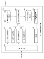
図2は、実施の形態に係るタイヤ摩耗状態管理装置200の構成図である。タイヤ摩耗状態管理装置200は、車両と通信可能なサーバの機能の一部として実装される。タイヤ摩耗状態管理装置200は、通信部48と、空気圧情報取得部32と、走行情報取得部36と、タイヤ摩耗状態推測部38と、を含んで構成される。タイヤ特性情報取得部30、温度情報取得部34、摩耗係数テーブル記録部40、タイヤ摩耗状態記録部42、空気圧調整提案生成部44、提示部46をさらに含む形態であってもよい。サーバは複数の車両と通信可能であり、タイヤ摩耗状態管理装置200は、複数の車両のタイヤ摩耗状態を管理することで、タイヤメーカにタイヤ摩耗状態の統計データを提供することもできる。これにより、タイヤメーカはタイヤの実際の使用状況についてより正確な情報を把握し、タイヤの開発や販売など活用して、ビジネスモデルを構築することができる。
タイヤ摩耗状態管理装置200は、車両に搭載されてもよい。このとき、タイヤ摩耗状態管理装置200は、空気圧情報取得部10と、走行情報取得部14と、タイヤ摩耗状態推測部38と、を含んで構成される。タイヤ摩耗状態推測部38は、空気圧情報を通信部48からでなく空気圧情報取得部10から取得し、走行情報を通信部48からでなく走行情報取得部14から取得する。タイヤ摩耗状態管理装置200は、通信部18、タイヤ特性情報取得部30、温度情報取得部12、摩耗係数テーブル記録部40、タイヤ摩耗状態記録部42、空気圧調整提案生成部44、及び通知部16をさらに含む形態であってもよい。摩耗係数テーブル記録部40、タイヤ摩耗状態記録部42がサーバなどの外部機器に備えられ、通信部18を介して情報の送受信を行ってもよい。
摩耗係数テーブル記録部40は、タイヤの摩耗係数テーブルを記録する。摩耗係数は空気圧とタイヤの接地面上の車軸方向の位置に応じて変化する。摩耗係数は、たとえば、0から1の間の値を取る。タイヤが路面に接地しない位置において、摩耗係数は0である。タイヤが路面に接地する位置であり、その位置にかかる車両重量が多いほど、または、摩擦が大きいと考えられるほど、1に近づく。タイヤが接地する位置については後述する。
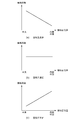
図3(a)~図3(c)は、摩耗係数テーブルを説明する図である。ここでは、摩耗係数テーブルをグラフの形式で表すが、実装上は、グラフ上の値をテーブルの形式で格納する。縦軸は摩耗係数の値であり、横軸はタイヤの接地面上の車軸方向の位置であり、タイヤの接地面において車軸方向に中央部から内側端部または外側端部へ変化する位置を示す。
図3(a)は、空気圧が過多である場合の摩耗係数を示す。空気圧過多の場合、タイヤの中央部が空気圧により膨らむため、タイヤの中央部だけが接地する、言い換えると、タイヤの内側端部/外側端部が接地しない、あるいはタイヤの内側端部/外側端部にかかる車両重量がタイヤの中央部より少ない状態での走行となる。言い換えると、タイヤ空気圧が高いほど、タイヤの中央部の摩耗係数が高く、タイヤの内側端部/外側端部の摩耗係数が低くなる。このためにタイヤの中央部が内側端部/外側端部よりも早く摩耗するため、摩耗係数のグラフは接地面上の位置に対して右下がりの傾斜になる。このように空気圧過多の場合、「センタ摩耗」が起きる。図3(a)におけるグラフの傾きは、空気圧の高さにより可変であり、またタイヤの特性や空気圧により、必ずしも直線ではない場合がある。
図3(b)は、空気圧が適正値である場合の摩耗係数を示す。空気圧適正の場合、タイヤの中央部およびタイヤの内側端部/外側端部が均等に接地し、タイヤの溝は均一に磨り減るため、摩耗係数のグラフは接地面上の位置に対して傾斜がない。図3(b)におけるグラフの傾きは、タイヤの特性や空気圧により、必ずしも直線ではない場合がある。
図3(c)は、空気圧が不足している場合の摩耗係数を示す。空気圧不足の場合、タイヤの中央部の膨らみが無く、タイヤの中央部が接地しない、言い換えると、タイヤの内側端部/外側端部だけが接地する、あるいはタイヤの内側端部/外側端部にかかる車両重量がタイヤの中央部より多い状態での走行となる。言い換えると、タイヤ空気圧が低いほど、タイヤの中央部の摩耗係数が低く、タイヤの内側端部/外側端部の摩耗係数が高くなる。このためにタイヤの内側端部/外側端部が中央部よりも早く摩耗するため、摩耗係数のグラフは接地面上の位置に対して右上がりの傾斜になる。このように空気圧不足の場合、「両肩べり摩耗」が起きる。図3(c)におけるグラフの傾きは、空気圧の高さにより可変であり、またタイヤの特性や空気圧により、必ずしも直線ではない場合がある。
摩耗係数は、空気圧以外にもタイヤの温度にも依存する。タイヤの温度によって摩耗係数を可変に設定してもよい。摩耗係数は、例えば、図3(a)におけるグラフの傾きを温度により可変とすることができる。温度が高いほど摩耗が起きやすいため、温度が高いほど、図3(a)におけるタイヤの接地位置であるタイヤの中央部の摩耗係数の値を高い値に変更し、図3(c)におけるタイヤの接地位置であるタイヤの内側端部/外側端部の摩耗係数の値を高い値に変更する。温度が高いほど、摩耗係数の値を全体に高い値に変更してもよい。また、摩耗係数は雨天や凍結などの路面状態にも依存するため、路面状態によって摩耗係数を可変に設定してもよい。摩耗係数は、雨天または路面凍結などの条件により可変とすることができ、たとえば雨天や路面凍結と判定された場合には摩耗が起きにくいため、タイヤの接地位置の摩耗係数の値を低い値に変更するか、または、摩耗係数の値を全体に低い値に変更する。雨天または路面の凍結は、ワイパーの動作有無をCANを介して取得して判定する、気温により路面の凍結を推測する、雨滴センサなどの専用センサを設ける、インターネットなどのネットワークにより情報を取得するなど、図示しない走行環境取得部により取得した情報によって、判定することができる。
摩耗係数は、走行速度、運転操作、路面状態などの影響も受ける。走行速度が速いほど、運転操作が急であるほど、路面状態が悪いほど、摩耗係数を高く設定してもよい。
四輪のタイヤの空気圧のバランスが悪い場合、特定のタイヤの摩耗が早く進むことがある。四輪のタイヤの空気圧のアンバランスに応じて各タイヤの摩耗係数を可変に設定してもよい。例えば、一輪だけが空気圧が低い場合には、その一輪にかかる抵抗が大きくなるため、摩耗係数を高くすることが考えられる、具体的には、全てのタイヤの空気圧の平均値と、各タイヤの空気圧との差異の多寡に応じて、空気圧が平均値より低い場合にはタイヤの内側端部/外側端部の摩耗係数を高く、空気圧が平均値より高い場合にはタイヤの内側端部/外側端部の摩耗係数を低くする。
タイヤ特性情報取得部30は、通信部48によりタイヤメーカのデータベースまたは走行情報管理装置100から受信したタイヤの特性情報を取得する。タイヤ特性情報取得部30は、タイヤの特性情報を摩耗係数テーブル記録部40に記録された摩耗係数テーブルに反映させる。たとえば、耐摩耗性能が向上したタイヤに交換した場合、摩耗係数テーブルに格納された摩耗係数の値を低い値に変更する。タイヤの材質により、耐摩耗性能が改善されている場合、摩耗係数テーブルに格納された摩耗係数の値を低い値に変更する。タイヤの材質または構造により、たとえばタイヤの内側端部/外側端部の耐摩耗性能が改善されている場合、摩耗係数テーブルに格納されたタイヤの内側端部/外側端部の摩耗係数の値を低い値に変更する。
空気圧情報取得部32は、通信部48により走行情報管理装置100から受信したタイヤの空気圧情報を取得し、タイヤ摩耗状態推測部38に与える。温度情報取得部34は、通信部48により走行情報管理装置100から受信したタイヤの温度情報を取得し、タイヤ摩耗状態推測部38に与える。走行情報取得部36は、通信部48により走行情報管理装置100から受信した車両の走行情報を取得し、タイヤ摩耗状態推測部38に与える。
タイヤ摩耗状態推測部38は、摩耗係数テーブル記録部40の摩耗係数テーブルを参照して、空気圧情報取得部32から与えられた空気圧に対応する摩耗係数の値を読み取る。タイヤ摩耗状態推測部38は、走行情報取得部36から与えられた走行情報に含まれる走行距離に、空気圧に対応する摩耗係数の値を乗算することにより、摩耗量を推測する。摩耗係数はタイヤの接地面上の位置によって異なるので、タイヤの接地面上の位置によって異なる摩耗量が求められる。すなわち、摩耗箇所に対応づけられた摩耗量がタイヤ摩耗状態の推測値として得られる。タイヤ摩耗状態推測部38は、摩耗箇所と摩耗量をタイヤ摩耗状態としてタイヤ摩耗状態記録部42に記録する。
タイヤ摩耗状態推測部38は、さらに温度情報取得部34から与えられた温度に対応する摩耗係数の値を読み取ってもよい。タイヤ摩耗状態推測部38は、与えられた空気圧と温度に対応する摩耗係数の値を走行距離に乗算することにより、摩耗箇所に応じた摩耗量を推測する。
空気圧調整提案生成部44は、タイヤ摩耗状態記録部42に蓄積されたタイヤ摩耗状態を参照して、摩耗箇所と摩耗量に応じて空気圧調整に関する提案を生成する。提示部46は、空気圧調整に関する提案を車両のドライバに通知するために、通信部48を介して空気圧調整に関する提案を走行情報管理装置100に送信する。提示部46は、タイヤ摩耗状態推測部38が推測したタイヤ摩耗状態を、通信部48を介して走行情報管理装置100に送信してもよい。
空気圧調整に関する提案には、タイヤのローテーションやタイヤ交換の指示、推測されたタイヤ摩耗状態にもとづいたより適切なタイヤ空気圧値の設定指示、偏摩耗を解消するために空気圧を上げるまたは下げる指示などが含まれる。
空気圧調整提案生成部44は、タイヤの一部の箇所の摩耗量が所定の閾値を超えたと推測される場合、タイヤの空気圧を調整する提案を生成してもよい。たとえば、タイヤの中央部の摩耗量が閾値を超えたと推測される場合、タイヤのセンタ摩耗を抑制するため、適正値より低い空気圧とする提案を生成する。またタイヤの内側端部または外側端部の摩耗量が閾値を超えたと推測される場合、タイヤの内側端部または外側端部の摩耗を抑制するため、適正値より高い空気圧をする提案を生成する。このような提案を生成することで、たとえば、タイヤのセンタがあまり摩耗しておらず、タイヤの内側端部または外側端部の摩耗量が大きい場合に、タイヤのセンタが接地しやすくなるようにタイヤ空気圧を高め、タイヤの内側端部または外側端部の摩耗量を抑制してタイヤの偏摩耗を防ぐ提案とすることができる。
空気圧調整提案生成部44は、タイヤの空気圧が適正値より高く、かつ、推測されるタイヤの摩耗状態がセンタ摩耗を示す場合、空気圧を下げる提案を生成し、タイヤの空気圧が適正値より低く、かつ、タイヤの推測される摩耗状態が肩摩耗を示す場合、空気圧を上げる提案を生成してもよい。
推測されたタイヤ摩耗状態が両肩べり摩耗であれば、適正な空気圧範囲のうち、やや高めの空気圧に調整するよう提案することで、タイヤのセンタの摩耗を早く、肩の減りを緩やかにさせることができる。推測されたタイヤ摩耗状態がセンタ摩耗であれば、適正な空気圧範囲のうち、やや低めの空気圧に調整するよう提案することで、タイヤのセンタの摩耗を抑え、肩の減りを早めることができる。
空気圧調整提案生成部44は、タイヤの中央部の摩耗量と内側端部または外側端部の摩耗量の差が所定の閾値を超えた場合すなわち偏摩耗が生じた場合、偏摩耗を解消する方向に空気圧を調整する提案を生成してもよい。中央部の摩耗量の方が内側端部または外側端部の摩耗量よりも大きい場合、空気圧を下げるように、内側端部または外側端部の摩耗量の方が中央部の摩耗量よりも大きい場合、空気圧を上げるように提案することで、タイヤの摩耗を均一にすることができる。
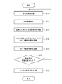
図4は、実施の形態のタイヤ摩耗状態管理装置200によるタイヤ摩耗状態管理手順を説明するフローチャートである。
空気圧情報取得部32は、走行情報管理装置100から車両の車輪に装着された各タイヤの空気圧情報を受信する(S10)。
温度情報取得部34は、走行情報管理装置100から車両の走行距離を含む走行情報を受信する(S12)。
タイヤ摩耗状態推測部38は、摩耗係数テーブル記録部40に記録された摩耗係数テーブルを参照して、受信したタイヤの空気圧に対応する摩耗係数を取得する(S14)。タイヤ摩耗状態推測部38は、摩耗係数と走行距離を掛け合わせることにより、摩耗箇所毎の摩耗量を推測し(S16)、タイヤ摩耗状態としてタイヤ摩耗状態記録部42に記録する(S18)。
空気圧調整提案生成部44は、タイヤ摩耗状態記録部42に記録されたタイヤ摩耗状態を参照し、摩耗量が閾値を超えた場合(S20のY)、タイヤの空気圧を調整する提案を生成する(S22)。摩耗量が閾値を超えない場合(S20のN)、ステップS10に戻り、タイヤ摩耗状態の推測と蓄積を繰り返す。
以上説明したように、本実施の形態のタイヤ摩耗状態管理装置200によれば、タイヤの摩耗状態として摩耗箇所と摩耗量を推測し、タイヤができるだけ均一に摩耗するように空気圧の調整をユーザに提案することができる。また、タイヤの摩耗状態を管理して、適切なタイヤのローテーションや交換の時期をユーザに通知することができる。
以上、本発明を実施の形態をもとに説明した。実施の形態は例示であり、それらの各構成要素や各処理プロセスの組合せにいろいろな変形例が可能なこと、またそうした変形例も本発明の範囲にあることは当業者に理解されるところである。
タイヤの摩耗要因には路面状態も影響する。走行情報取得部36は、GPS(Global Positioning System)からの位置情報を参照して走行した路面の舗装の有無や材質などの情報、天候情報を参照して雨天や凍結などの路面の摩擦率の情報などを路面状態情報として、走行情報に含めて取得する。タイヤ摩耗状態推測部38は、路面状態情報をさらにパラメータに加えて、タイヤ摩耗状態を推測してもよい。
タイヤの摩耗要因には車両の運転操作も影響する。車両の急ブレーキ、急発進によってタイヤの摩耗が早く進んだり、急ハンドルがタイヤの局部摩耗の要因となることがある。走行情報取得部36は、走行情報として、アクセル操作、ブレーキ操作、ハンドル操作などの運転操作情報をさらに取得し、タイヤ摩耗状態推測部38は、運転操作情報をさらにパラメータに加えて、タイヤ摩耗状態を推測してもよい。
なお、実施の形態で説明した各装置の機能構成はハードウェア資源またはソフトウェア資源により、あるいはハードウェア資源とソフトウェア資源の協働により実現できる。ハードウェア資源としてプロセッサ、ROM、RAM、その他のLSIを利用できる。ソフトウェア資源としてオペレーティングシステム、アプリケーション等のプログラムを利用できる。
本発明は、タイヤ摩耗状態を管理する技術に利用できる。
10 空気圧情報取得部、 12 温度情報取得部、 14 走行情報取得部、 16 通知部、 18 通信部、 30 タイヤ特性情報取得部、 32 空気圧情報取得部、 34 温度情報取得部、 36 走行情報取得部、 38 タイヤ摩耗状態推測部、 40 摩耗係数テーブル記録部、 42 タイヤ摩耗状態記録部、 44 空気圧調整提案生成部、 46 提示部、 48 通信部、 100 走行情報管理装置、 200 タイヤ摩耗状態管理装置。
Claims (9)
- 車両が備える車輪に装着される各タイヤの空気圧情報を取得する空気圧情報取得部と、
前記車両の走行距離を含む走行情報を取得する走行情報取得部と、
前記タイヤの空気圧情報に依存する摩耗係数と前記走行情報に基づいて前記タイヤの摩耗状態を推測するタイヤ摩耗状態推測部と、を備えることを特徴とするタイヤ摩耗状態管理装置。 - 前記摩耗係数は前記タイヤの接地面上の車軸方向の位置に応じて設定され、前記空気圧が高くなるに従って、タイヤの接地面上の車軸方向の中央部の摩耗係数が高く、タイヤの接地面上の車軸方向の内側端部または外側端部の摩耗係数が低く設定されることを特徴とする請求項1に記載のタイヤ摩耗状態管理装置。
- 前記タイヤの特性情報を取得するタイヤ特性情報取得部をさらに備え、
前記摩耗係数は前記タイヤの空気圧情報および前記タイヤの特性情報に依存して設定されることを特徴とする請求項1または2に記載のタイヤ摩耗状態管理装置。 - 前記タイヤの温度情報を取得する温度情報取得部をさらに備え、
前記摩耗係数は前記タイヤの空気圧情報および前記温度情報に依存して設定されることを特徴とする請求項1から3のいずれかに記載のタイヤ摩耗状態管理装置。 - 前記車両が走行する車両周囲の走行環境情報を取得する走行環境取得部をさらに備え、
前記摩耗係数は前記タイヤの空気圧情報および前記走行環境情報に依存して設定されることを特徴とする請求項1から4のいずれかに記載のタイヤ摩耗状態管理装置。 - 前記推測されたタイヤの摩耗状態に基づいて、前記タイヤの空気圧調整に関する提案を生成する空気圧調整提案生成部をさらに備え、
前記空気圧調整提案生成部は、前記タイヤの少なくとも一部の箇所の摩耗量が所定の閾値を超えたと推測された場合、または、前記タイヤの接地面上の車軸方向の中央部の摩耗量と接地面上の車軸方向の内側端部または外側端部の摩耗量の差が所定の閾値を超えた場合、前記タイヤの空気圧調整に関する提案を生成することを特徴とする請求項1から5のいずれかに記載のタイヤ摩耗状態管理装置。 - 前記推測されたタイヤの摩耗状態に基づいて、前記タイヤの空気圧調整に関する提案を生成する空気圧調整提案生成部をさらに備え、
前記空気圧調整提案生成部は、前記タイヤの空気圧が所定の適正値より高く、かつ、前記推測されたタイヤの摩耗状態が前記タイヤのセンタ摩耗を示す場合、または、前記タイヤの空気圧が前記所定の適正値より低く、かつ、前記推測されたタイヤの摩耗状態が前記タイヤの肩摩耗を示す場合、前記タイヤの空気圧調整に関する提案を生成することを特徴とする請求項1から5のいずれかに記載のタイヤ摩耗状態管理装置。 - 車両が備える車輪に装着される各タイヤの空気圧情報を取得する空気圧情報取得ステップと、
前記車両の走行距離を含む走行情報を取得する走行情報取得ステップと、
前記タイヤの空気圧情報に依存する摩耗係数と前記走行情報に基づいて前記タイヤの摩耗状態を推測するタイヤ摩耗状態推測ステップと、を備えることを特徴とするタイヤ摩耗状態管理方法。 - 車両が備える車輪に装着される各タイヤの空気圧情報を取得する空気圧情報取得ステップと、
前記車両の走行距離を含む走行情報を取得する走行情報取得ステップと、
前記タイヤの空気圧情報に依存する摩耗係数と前記走行情報に基づいて前記タイヤの摩耗状態を推測するタイヤ摩耗状態推測ステップと、をコンピュータに実行させることを特徴とするタイヤ摩耗状態管理プログラム。
Applications Claiming Priority (2)
| Application Number | Priority Date | Filing Date | Title |
|---|---|---|---|
| JP2019-050623 | 2019-03-19 | ||
| JP2019050623A JP2020152171A (ja) | 2019-03-19 | 2019-03-19 | タイヤ摩耗状態管理装置、タイヤ摩耗状態管理方法、及びタイヤ摩耗状態管理プログラム |
Publications (1)
| Publication Number | Publication Date |
|---|---|
| WO2020188911A1 true WO2020188911A1 (ja) | 2020-09-24 |
Family
ID=72519814
Family Applications (1)
| Application Number | Title | Priority Date | Filing Date |
|---|---|---|---|
| PCT/JP2019/048421 Ceased WO2020188911A1 (ja) | 2019-03-19 | 2019-12-11 | タイヤ摩耗状態管理装置、タイヤ摩耗状態管理方法、及びタイヤ摩耗状態管理プログラム |
Country Status (2)
| Country | Link |
|---|---|
| JP (1) | JP2020152171A (ja) |
| WO (1) | WO2020188911A1 (ja) |
Families Citing this family (5)
| Publication number | Priority date | Publication date | Assignee | Title |
|---|---|---|---|---|
| WO2022202159A1 (ja) * | 2021-03-23 | 2022-09-29 | 本田技研工業株式会社 | タイヤ消耗度管理装置 |
| JP7845830B2 (ja) * | 2021-07-30 | 2026-04-14 | Toyo Tire株式会社 | タイヤダメージ蓄積量推定システム、演算モデル生成システムおよびタイヤダメージ蓄積量推定方法 |
| JP7675596B2 (ja) * | 2021-08-23 | 2025-05-13 | 株式会社ブリヂストン | タイヤ管理装置、タイヤ管理プログラムおよびタイヤ管理方法 |
| JP2023151522A (ja) * | 2022-03-31 | 2023-10-16 | 株式会社ブリヂストン | 情報処理装置、情報処理方法、及び情報処理プログラム |
| JP2026052458A (ja) * | 2024-09-11 | 2026-03-24 | 株式会社ブリヂストン | タイヤ管理装置、プログラム及びタイヤ管理方法 |
Citations (5)
| Publication number | Priority date | Publication date | Assignee | Title |
|---|---|---|---|---|
| JPH106722A (ja) * | 1996-06-25 | 1998-01-13 | Mitsubishi Materials Corp | 車両用ラジアルタイヤの空気圧調整方法 |
| JP2002131191A (ja) * | 2000-10-18 | 2002-05-09 | Yokohama Rubber Co Ltd:The | 車両タイヤの管理方法 |
| JP2005349966A (ja) * | 2004-06-11 | 2005-12-22 | Nippon Yusoki Co Ltd | タイヤ摩耗検知装置及びこれを備える産業車両 |
| KR20110061973A (ko) * | 2009-12-02 | 2011-06-10 | 현대모비스 주식회사 | 타이어 변형 검출장치 및 검출방법 |
| JP2013113724A (ja) * | 2011-11-29 | 2013-06-10 | Bridgestone Corp | タイヤ摩耗予測方法及びタイヤ摩耗予測装置 |
-
2019
- 2019-03-19 JP JP2019050623A patent/JP2020152171A/ja active Pending
- 2019-12-11 WO PCT/JP2019/048421 patent/WO2020188911A1/ja not_active Ceased
Patent Citations (5)
| Publication number | Priority date | Publication date | Assignee | Title |
|---|---|---|---|---|
| JPH106722A (ja) * | 1996-06-25 | 1998-01-13 | Mitsubishi Materials Corp | 車両用ラジアルタイヤの空気圧調整方法 |
| JP2002131191A (ja) * | 2000-10-18 | 2002-05-09 | Yokohama Rubber Co Ltd:The | 車両タイヤの管理方法 |
| JP2005349966A (ja) * | 2004-06-11 | 2005-12-22 | Nippon Yusoki Co Ltd | タイヤ摩耗検知装置及びこれを備える産業車両 |
| KR20110061973A (ko) * | 2009-12-02 | 2011-06-10 | 현대모비스 주식회사 | 타이어 변형 검출장치 및 검출방법 |
| JP2013113724A (ja) * | 2011-11-29 | 2013-06-10 | Bridgestone Corp | タイヤ摩耗予測方法及びタイヤ摩耗予測装置 |
Also Published As
| Publication number | Publication date |
|---|---|
| JP2020152171A (ja) | 2020-09-24 |
Similar Documents
| Publication | Publication Date | Title |
|---|---|---|
| WO2020188911A1 (ja) | タイヤ摩耗状態管理装置、タイヤ摩耗状態管理方法、及びタイヤ摩耗状態管理プログラム | |
| US20230294459A1 (en) | Model based tire wear estimation system and method | |
| US10809742B2 (en) | System and method for tire sensor-based autonomous vehicle fleet management | |
| CN111746299B (zh) | 控制电动车辆的牵引的系统、方法以及电动车辆 | |
| JP6244027B2 (ja) | タイヤの分類 | |
| JP4868689B2 (ja) | 路面状態推定方法、及び、路面状態推定装置 | |
| EP3838628A1 (en) | Method of estimating tire conditions | |
| JP7603101B2 (ja) | タイヤ摩耗予測システム、タイヤ摩耗予測プログラム、タイヤ摩耗予測方法及びデータ構造 | |
| JP2016536596A (ja) | 路面における短期凹凸の検出 | |
| JP6694959B2 (ja) | タイヤ剛性の推定および道路摩擦の推定 | |
| US20160323659A1 (en) | Tire sensor-based mileage tracking system and method | |
| JP2023540204A (ja) | 温度上昇データを使用する車両タイヤ位置特定システム及び方法 | |
| JP2022100865A (ja) | タイヤの摩耗状態の推定装置 | |
| CN110446619A (zh) | 用于确定车辆车轮上的车轮载荷的方法和设备 | |
| US20230196854A1 (en) | Tire replacement system | |
| US20210394562A1 (en) | Model based tire wear estimation system and method | |
| WO2022214175A1 (en) | Tyre wear rate estimation based on a dynamic tyre model | |
| GB2552011B (en) | A controller for a vehicle system | |
| EP4494900B1 (en) | Device and method for automatically determining wear of tires | |
| WO2022214173A1 (en) | Tyre rolling resistance estimation based on a dynamic tyre model | |
| JP5705051B2 (ja) | 路面状態推定方法、及び路面状態推定装置 | |
| EP4140838B1 (en) | Road condition monitoring system and method | |
| JP7676925B2 (ja) | 車両制御装置および車両制御システム | |
| JP2019190959A (ja) | タイヤ交換判断装置 | |
| CN116278523B (zh) | 轮胎更换系统 |
Legal Events
| Date | Code | Title | Description |
|---|---|---|---|
| 121 | Ep: the epo has been informed by wipo that ep was designated in this application |
Ref document number: 19920229 Country of ref document: EP Kind code of ref document: A1 |
|
| NENP | Non-entry into the national phase |
Ref country code: DE |
|
| 122 | Ep: pct application non-entry in european phase |
Ref document number: 19920229 Country of ref document: EP Kind code of ref document: A1 |