WO2020188762A1 - Endoscope à ultrasons - Google Patents
Endoscope à ultrasons Download PDFInfo
- Publication number
- WO2020188762A1 WO2020188762A1 PCT/JP2019/011531 JP2019011531W WO2020188762A1 WO 2020188762 A1 WO2020188762 A1 WO 2020188762A1 JP 2019011531 W JP2019011531 W JP 2019011531W WO 2020188762 A1 WO2020188762 A1 WO 2020188762A1
- Authority
- WO
- WIPO (PCT)
- Prior art keywords
- support member
- ultrasonic endoscope
- central axis
- hole
- ultrasonic
- Prior art date
Links
- 230000003287 optical effect Effects 0.000 claims abstract description 28
- 238000003780 insertion Methods 0.000 claims abstract description 27
- 230000037431 insertion Effects 0.000 claims abstract description 27
- XLYOFNOQVPJJNP-UHFFFAOYSA-N water Substances O XLYOFNOQVPJJNP-UHFFFAOYSA-N 0.000 claims description 22
- 238000005286 illumination Methods 0.000 claims description 16
- 239000000463 material Substances 0.000 claims description 11
- 238000002627 tracheal intubation Methods 0.000 claims description 10
- 239000012530 fluid Substances 0.000 claims description 7
- 238000010292 electrical insulation Methods 0.000 claims description 4
- 238000010586 diagram Methods 0.000 description 30
- 230000000694 effects Effects 0.000 description 10
- 230000002093 peripheral effect Effects 0.000 description 9
- 239000000853 adhesive Substances 0.000 description 6
- 230000001070 adhesive effect Effects 0.000 description 6
- 238000003384 imaging method Methods 0.000 description 4
- 238000005452 bending Methods 0.000 description 3
- 239000000126 substance Substances 0.000 description 3
- MCMNRKCIXSYSNV-UHFFFAOYSA-N Zirconium dioxide Chemical compound O=[Zr]=O MCMNRKCIXSYSNV-UHFFFAOYSA-N 0.000 description 2
- 238000005401 electroluminescence Methods 0.000 description 2
- 239000000945 filler Substances 0.000 description 2
- 238000000034 method Methods 0.000 description 2
- 239000000758 substrate Substances 0.000 description 2
- 239000008400 supply water Substances 0.000 description 2
- PNEYBMLMFCGWSK-UHFFFAOYSA-N aluminium oxide Inorganic materials [O-2].[O-2].[O-2].[Al+3].[Al+3] PNEYBMLMFCGWSK-UHFFFAOYSA-N 0.000 description 1
- 238000010276 construction Methods 0.000 description 1
- 238000013016 damping Methods 0.000 description 1
- 238000003745 diagnosis Methods 0.000 description 1
- 239000003822 epoxy resin Substances 0.000 description 1
- 239000004973 liquid crystal related substance Substances 0.000 description 1
- 230000000149 penetrating effect Effects 0.000 description 1
- 229920000647 polyepoxide Polymers 0.000 description 1
- 229920002050 silicone resin Polymers 0.000 description 1
Images


Classifications
-
- B—PERFORMING OPERATIONS; TRANSPORTING
- B06—GENERATING OR TRANSMITTING MECHANICAL VIBRATIONS IN GENERAL
- B06B—METHODS OR APPARATUS FOR GENERATING OR TRANSMITTING MECHANICAL VIBRATIONS OF INFRASONIC, SONIC, OR ULTRASONIC FREQUENCY, e.g. FOR PERFORMING MECHANICAL WORK IN GENERAL
- B06B1/00—Methods or apparatus for generating mechanical vibrations of infrasonic, sonic, or ultrasonic frequency
- B06B1/02—Methods or apparatus for generating mechanical vibrations of infrasonic, sonic, or ultrasonic frequency making use of electrical energy
- B06B1/06—Methods or apparatus for generating mechanical vibrations of infrasonic, sonic, or ultrasonic frequency making use of electrical energy operating with piezoelectric effect or with electrostriction
- B06B1/0607—Methods or apparatus for generating mechanical vibrations of infrasonic, sonic, or ultrasonic frequency making use of electrical energy operating with piezoelectric effect or with electrostriction using multiple elements
- B06B1/0622—Methods or apparatus for generating mechanical vibrations of infrasonic, sonic, or ultrasonic frequency making use of electrical energy operating with piezoelectric effect or with electrostriction using multiple elements on one surface
- B06B1/0633—Cylindrical array
-
- A—HUMAN NECESSITIES
- A61—MEDICAL OR VETERINARY SCIENCE; HYGIENE
- A61B—DIAGNOSIS; SURGERY; IDENTIFICATION
- A61B1/00—Instruments for performing medical examinations of the interior of cavities or tubes of the body by visual or photographical inspection, e.g. endoscopes; Illuminating arrangements therefor
- A61B1/00064—Constructional details of the endoscope body
- A61B1/00071—Insertion part of the endoscope body
- A61B1/0008—Insertion part of the endoscope body characterised by distal tip features
-
- A—HUMAN NECESSITIES
- A61—MEDICAL OR VETERINARY SCIENCE; HYGIENE
- A61B—DIAGNOSIS; SURGERY; IDENTIFICATION
- A61B1/00—Instruments for performing medical examinations of the interior of cavities or tubes of the body by visual or photographical inspection, e.g. endoscopes; Illuminating arrangements therefor
- A61B1/00064—Constructional details of the endoscope body
- A61B1/0011—Manufacturing of endoscope parts
-
- A—HUMAN NECESSITIES
- A61—MEDICAL OR VETERINARY SCIENCE; HYGIENE
- A61B—DIAGNOSIS; SURGERY; IDENTIFICATION
- A61B1/00—Instruments for performing medical examinations of the interior of cavities or tubes of the body by visual or photographical inspection, e.g. endoscopes; Illuminating arrangements therefor
- A61B1/00131—Accessories for endoscopes
- A61B1/00137—End pieces at either end of the endoscope, e.g. caps, seals or forceps plugs
-
- A—HUMAN NECESSITIES
- A61—MEDICAL OR VETERINARY SCIENCE; HYGIENE
- A61B—DIAGNOSIS; SURGERY; IDENTIFICATION
- A61B1/00—Instruments for performing medical examinations of the interior of cavities or tubes of the body by visual or photographical inspection, e.g. endoscopes; Illuminating arrangements therefor
- A61B1/012—Instruments for performing medical examinations of the interior of cavities or tubes of the body by visual or photographical inspection, e.g. endoscopes; Illuminating arrangements therefor characterised by internal passages or accessories therefor
- A61B1/015—Control of fluid supply or evacuation
-
- A—HUMAN NECESSITIES
- A61—MEDICAL OR VETERINARY SCIENCE; HYGIENE
- A61B—DIAGNOSIS; SURGERY; IDENTIFICATION
- A61B1/00—Instruments for performing medical examinations of the interior of cavities or tubes of the body by visual or photographical inspection, e.g. endoscopes; Illuminating arrangements therefor
- A61B1/012—Instruments for performing medical examinations of the interior of cavities or tubes of the body by visual or photographical inspection, e.g. endoscopes; Illuminating arrangements therefor characterised by internal passages or accessories therefor
- A61B1/018—Instruments for performing medical examinations of the interior of cavities or tubes of the body by visual or photographical inspection, e.g. endoscopes; Illuminating arrangements therefor characterised by internal passages or accessories therefor for receiving instruments
-
- A—HUMAN NECESSITIES
- A61—MEDICAL OR VETERINARY SCIENCE; HYGIENE
- A61B—DIAGNOSIS; SURGERY; IDENTIFICATION
- A61B1/00—Instruments for performing medical examinations of the interior of cavities or tubes of the body by visual or photographical inspection, e.g. endoscopes; Illuminating arrangements therefor
- A61B1/04—Instruments for performing medical examinations of the interior of cavities or tubes of the body by visual or photographical inspection, e.g. endoscopes; Illuminating arrangements therefor combined with photographic or television appliances
- A61B1/05—Instruments for performing medical examinations of the interior of cavities or tubes of the body by visual or photographical inspection, e.g. endoscopes; Illuminating arrangements therefor combined with photographic or television appliances characterised by the image sensor, e.g. camera, being in the distal end portion
- A61B1/051—Details of CCD assembly
-
- A—HUMAN NECESSITIES
- A61—MEDICAL OR VETERINARY SCIENCE; HYGIENE
- A61B—DIAGNOSIS; SURGERY; IDENTIFICATION
- A61B8/00—Diagnosis using ultrasonic, sonic or infrasonic waves
- A61B8/12—Diagnosis using ultrasonic, sonic or infrasonic waves in body cavities or body tracts, e.g. by using catheters
-
- A—HUMAN NECESSITIES
- A61—MEDICAL OR VETERINARY SCIENCE; HYGIENE
- A61B—DIAGNOSIS; SURGERY; IDENTIFICATION
- A61B8/00—Diagnosis using ultrasonic, sonic or infrasonic waves
- A61B8/44—Constructional features of the ultrasonic, sonic or infrasonic diagnostic device
- A61B8/4444—Constructional features of the ultrasonic, sonic or infrasonic diagnostic device related to the probe
- A61B8/445—Details of catheter construction
-
- A—HUMAN NECESSITIES
- A61—MEDICAL OR VETERINARY SCIENCE; HYGIENE
- A61B—DIAGNOSIS; SURGERY; IDENTIFICATION
- A61B8/00—Diagnosis using ultrasonic, sonic or infrasonic waves
- A61B8/44—Constructional features of the ultrasonic, sonic or infrasonic diagnostic device
- A61B8/4483—Constructional features of the ultrasonic, sonic or infrasonic diagnostic device characterised by features of the ultrasound transducer
- A61B8/4494—Constructional features of the ultrasonic, sonic or infrasonic diagnostic device characterised by features of the ultrasound transducer characterised by the arrangement of the transducer elements
-
- B—PERFORMING OPERATIONS; TRANSPORTING
- B06—GENERATING OR TRANSMITTING MECHANICAL VIBRATIONS IN GENERAL
- B06B—METHODS OR APPARATUS FOR GENERATING OR TRANSMITTING MECHANICAL VIBRATIONS OF INFRASONIC, SONIC, OR ULTRASONIC FREQUENCY, e.g. FOR PERFORMING MECHANICAL WORK IN GENERAL
- B06B1/00—Methods or apparatus for generating mechanical vibrations of infrasonic, sonic, or ultrasonic frequency
- B06B1/02—Methods or apparatus for generating mechanical vibrations of infrasonic, sonic, or ultrasonic frequency making use of electrical energy
- B06B1/06—Methods or apparatus for generating mechanical vibrations of infrasonic, sonic, or ultrasonic frequency making use of electrical energy operating with piezoelectric effect or with electrostriction
- B06B1/0607—Methods or apparatus for generating mechanical vibrations of infrasonic, sonic, or ultrasonic frequency making use of electrical energy operating with piezoelectric effect or with electrostriction using multiple elements
Definitions
- the present invention relates to an ultrasonic endoscope.
- a direct-view radial type ultrasonic endoscope is known as an ultrasonic endoscope provided with an insertion tube to be inserted into a subject (see, for example, Patent Document 1).
- the insertion tubes are arranged along the circumferential direction surrounding the central axis of the insertion tube, and have a transducer having a plurality of piezoelectric elements for emitting ultrasonic waves, and a subject image.
- An observation optical member to be taken in and a support member for supporting the observation optical member are provided.
- the transducer is provided with a first through hole that penetrates along the central axis of the intubation tube.
- the support member is provided with a second through hole that penetrates along the central axis. Then, the observation optical member is supported by the support member in a state of being inserted into the second through hole. Further, the support member is inserted into the first through hole while supporting the observation optical member.
- a portion of the support member that supports the observation optical member is formed by a through hole. That is, a wall thickness of a predetermined dimension is provided between the outer peripheral surface of the support member and the inner surface of the through hole. Therefore, there is a problem that the diameter of the support member cannot be reduced, and eventually the diameter of the intubation tube cannot be reduced, depending on the size of the wall thickness.
- the present invention has been made in view of the above, and an object of the present invention is to provide an ultrasonic endoscope capable of reducing the diameter of an insertion tube.
- the ultrasonic endoscope includes an insertion tube to be inserted into a subject, and the insertion tube surrounds the central axis of the insertion tube.
- a transducer having a plurality of piezoelectric elements arranged along the circumferential direction and emitting ultrasonic waves, a structure including an observation optical member for capturing a subject image, and a support member for supporting the structure are provided.
- the transducer is provided with a through hole that penetrates along the central axis and through which the structure and the support member are inserted, and the support member has at least one recess extending along the central axis.
- a groove is provided, and the structure is supported by the support member in a state of being inserted into the concave groove.
- the ultrasonic endoscope according to the present invention includes an insertion tube to be inserted into a subject, and the insertion tubes are arranged along the circumferential direction surrounding the central axis of the insertion tube and emit ultrasonic waves, respectively.
- a transducer having a plurality of piezoelectric elements, a structure including an observation optical member that captures a subject image, and a support member that supports the structure are provided, and the transducer penetrates along the central axis and is described.
- a through hole through which the structure and the support member are inserted is provided, and the support member includes a plurality of first supports separated from each other in a plane orthogonal to the central axis, and the plurality of first supports.
- a second support for integrating the support is provided, and the structure is supported by the support member in a state of being sandwiched between the plurality of first supports.
- the diameter of the intubation can be reduced.
- FIG. 1 is a diagram showing an endoscope system according to the first embodiment.
- FIG. 2 is a diagram showing the configuration of the tip unit.
- FIG. 3 is a diagram showing the configuration of the tip unit.
- FIG. 4 is a diagram showing the configuration of the tip unit.
- FIG. 5 is a diagram showing the configuration of the tip unit.
- FIG. 6 is a diagram showing the configuration of the transducer.
- FIG. 7 is a diagram showing the configuration of the transducer.
- FIG. 8 is a diagram showing the configuration of the support member.
- FIG. 9 is a diagram illustrating the effect of the first embodiment.
- FIG. 10 is a diagram illustrating the effect of the first embodiment.
- FIG. 11 is a diagram showing a configuration of a tip unit according to the second embodiment.
- FIG. 12 is a diagram showing a configuration of an imaging lens.
- FIG. 13 is a diagram showing a configuration of a tip unit according to the third embodiment.
- FIG. 14 is a diagram showing the configuration of the tip member.
- FIG. 15 is a diagram showing a configuration of a tip unit according to the fourth embodiment.
- FIG. 16 is a diagram showing a configuration of a tip unit according to the fourth embodiment.
- FIG. 1 is a diagram showing an endoscope system 1 according to the first embodiment.
- the endoscopic system 1 is a system for performing ultrasonic diagnosis in a subject such as a person by using an ultrasonic endoscope.
- the endoscope system 1 includes an ultrasonic endoscope 2, an ultrasonic observation device 3, an endoscope observation device 4, and a display device 5.
- a part of the ultrasonic endoscope 2 can be inserted into the subject.
- the ultrasonic endoscope 2 has a function of transmitting an ultrasonic pulse (acoustic pulse) toward the body wall in the subject and outputting an echo signal by receiving an ultrasonic echo reflected by the subject. It also has a function of outputting an image signal by imaging the inside of the subject.
- the detailed configuration of the ultrasonic endoscope 2 will be described later.
- the ultrasonic observation device 3 is electrically connected to the ultrasonic endoscope 2 via an ultrasonic cable 3a (FIG. 1). Then, the ultrasonic observation device 3 outputs a pulse signal to the ultrasonic endoscope 2 via the ultrasonic cable 3a and inputs an echo signal from the ultrasonic endoscope 2. Further, the ultrasonic observation device 3 generates an ultrasonic image by performing a predetermined process on the echo signal.
- An endoscope connector 9 (FIG. 1), which will be described later, of the ultrasonic endoscope 2 is detachably connected to the endoscope observation device 4.
- the endoscopic observation device 4 includes a video processor 4a and a light source device 4b.
- the video processor 4a inputs an image signal from the ultrasonic endoscope 2 via the endoscope connector 9. Then, the video processor 4a generates an endoscopic image by performing a predetermined process on the image signal.
- the light source device 4b supplies illumination light for illuminating the inside of the subject to the ultrasonic endoscope 2 via the endoscope connector 9.
- the display device 5 is configured by using a liquid crystal or an organic EL (Electro Luminescence), and displays an ultrasonic image generated by the ultrasonic observation device 3, an endoscopic image generated by the endoscopic observation device 4, and the like. To do.
- the ultrasonic endoscope 2 includes an insertion tube 6, an operation unit 7, a universal cord 8, and an endoscope connector 9.
- the insertion tube 6 is a portion to be inserted into the subject.
- one side (the tip side in the insertion direction into the subject) along the central axis Ax (FIG. 1) of the insertion tube 6 is described as the tip side Ar1, and the other side (operation unit 7 side). Is referred to as base end side Ar2.
- FIG. 1 the tip side in the insertion direction into the subject
- the insertion tube 6 has a tip unit 10 provided at the tip, a curved portion 6a which is connected to the proximal end side Ar2 of the distal end unit 10 and is bendable, and a proximal end of the curved portion 6a.
- a flexible tube 6b connected to the side Ar2 and having flexibility is provided. The detailed configuration of the tip unit 10 will be described later.
- the operation unit 7 is connected to Ar2 on the proximal end side of the intubation tube 6 and receives various operations from a doctor or the like. As shown in FIG. 1, the operation unit 7 includes a bending knob 7a for performing a bending operation on the bending portion 6a, and a plurality of operating members 7b for performing various operations. Further, the operating portion 7 communicates with the pipe 110 provided in the tip unit 10 via a tube (not shown) provided inside the curved portion 6a and the flexible tube 6b, and punctures the tube. A treatment tool insertion port 7c for inserting a treatment tool (not shown) such as the above is provided.
- the universal code 8 extends from the operation unit 7 and transmits a pair of light guides 51 (see FIGS. 2 to 5) that transmit illumination light supplied from the light source device 4b, and the pulse signal and echo signal described above.
- the transducer cable 71 (see FIGS. 2, 3 and 5), the signal cable 61 for transmitting the above-mentioned image signal (see FIGS. 3 and 5), and the balloon water supply pipeline for circulating the fluid (not shown).
- a cord for balloon suction (not shown), and an air supply / water supply line 81 (see FIG. 4).
- a pair of light guides 51, an oscillator cable 71, a signal cable 61, a balloon water supply pipe (not shown), a balloon suction pipe (not shown), and An air supply / water supply pipeline 81 is provided inside the insertion pipe 6 and the operation unit 7, a pair of light guides 51, an oscillator cable 71, a signal cable 61, a balloon water supply pipe (not shown), a balloon suction pipe (not shown), and An air supply / water supply pipeline 81 is provided.
- the endoscope connector 9 is provided at the end of the universal cord 8. Then, the endoscope connector 9 is connected to the ultrasonic cable 3a and is connected to the video processor 4a and the light source device 4b by being inserted into the endoscope observation device 4.
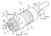
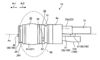
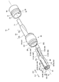
- FIGS. 2 to 5 are views showing the configuration of the tip unit 10.
- FIG. 2 is a perspective view of the tip unit 10 as viewed from the tip side Ar1.
- FIG. 3 is a side view of the tip unit 10 viewed from a direction orthogonal to the central axis Ax.
- FIG. 4 is a diagram showing the tip of the tip unit 10.
- FIG. 5 is an exploded perspective view of the tip unit 10 disassembled.
- the tip unit 10 includes a transducer 20, a connecting member 30 (FIGS. 2, 3 and 5), and a support member 40 (FIGS. 2, 4 and 5). ..
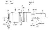
- FIG. 6 and 7 are diagrams showing the configuration of the transducer 20.
- FIG. 6 is a side view of the transducer 20 viewed from a direction orthogonal to the central axis Ax.
- FIG. 7 is a cross-sectional view of the transducer 20 cut by a plane including the central axis Ax.
- the transducer 20 is an electronic radial scanning type transducer. Then, the transducer 20 transmits an ultrasonic pulse in a direction orthogonal to the central axis Ax, and scans the ultrasonic pulse in a rotation direction of 360 ° about the central axis Ax.
- the transducer 20 includes an oscillator unit 21, a tubular member 22, a holding member 23, and a tip member 24.
- the oscillator unit 21 is a unit in which a plurality of piezoelectric elements 21a, an acoustic matching layer 21b, an acoustic lens 21c, and a backing material 21d are integrated, and is coaxial with the central axis Ax. It has a cylindrical shape.
- the plurality of piezoelectric elements 21a are regularly arranged along the circumferential direction surrounding the central axis Ax.
- the plurality of piezoelectric elements 21a all have the same shape, and each has a rectangular parallelepiped shape extending linearly along the central axis Ax.
- a pair of electrodes (not shown) are formed on the outer surface of the piezoelectric element 21a.
- the piezoelectric element 21a converts the pulse signal input by passing through the pair of electrodes into an ultrasonic pulse and transmits it to the subject. Further, the piezoelectric element 21a converts the ultrasonic echo reflected by the subject into an electrical echo signal.
- the acoustic matching layer 21b is provided on the outer surface side (the side separated from the central axis Ax) of the vibrator unit 21 with respect to the piezoelectric element 21a, and has a cylindrical shape.
- the acoustic matching layer 21b is a member that matches the acoustic impedance between the piezoelectric element 21a and the subject in order to efficiently transmit sound (ultrasonic waves) between the piezoelectric element 21a and the subject.
- the acoustic matching layer 21b is composed of one layer, but may be two or more layers depending on the characteristics of the piezoelectric element 21a and the subject. Further, the acoustic matching layer 21b may adopt a configuration that does not have the acoustic matching layer 21b as long as the acoustic impedance is matched with the subject.
- the acoustic lens 21c is made of, for example, a silicone resin or the like, and has a substantially cylindrical shape with a convexly curved outer peripheral surface as shown in FIG. 6 or 7, and constitutes the outer surface of the vibrator unit 21. To do. Then, the acoustic lens 21c has a function of converging the ultrasonic pulse transmitted from the piezoelectric element 21a and passing through the acoustic matching layer 21b.
- the acoustic lens 21c can be arbitrarily provided, and a configuration that does not have the acoustic lens 21c may be adopted.
- the backing material 21d is located on the inner side of the vibrator unit 21 (the side close to the central axis Ax) with respect to the piezoelectric element 21a, and is formed in a cylindrical shape. Then, the backing material 21d attenuates unnecessary ultrasonic vibration generated by the operation of the piezoelectric element 21a.
- the backing material 21d is formed by using a material having a large damping factor, for example, an epoxy resin in which a filler such as alumina or zirconia is dispersed, or a rubber in which the above-mentioned filler is dispersed.
- the tubular member 22 is made of a material having electrical insulation, and is formed in a cylindrical shape having an outer diameter dimension slightly smaller than the inner diameter dimension of the vibrator unit 21. Then, as shown in FIG. 7, the oscillator unit 21 is fixed to the outer peripheral surface of the tubular member 22.
- the holding member 23 is made of a material having electrical insulation. In the first embodiment, the holding member 23 is integrally formed with the end portion of the base end side Ar2 of the tubular member 22. As shown in FIG. 7, the holding member 23 includes first and second tubular portions 23a and 23b. The first tubular portion 23a extends along the central axis Ax and has a cylindrical shape having a diameter smaller than that of the tubular member 22. Then, the first tubular portion 23a holds the oscillator cable 71 in a state where the oscillator cable 71 is inserted.
- the second tubular portion 23b has an arc shape in a cross-sectional view (cross-sectional view cut by a plane orthogonal to the central axis Ax), and is formed in a tubular shape extending along the central axis Ax.
- the end portion of the base end side Ar2 in the second tubular portion 23b is connected to the end portion of the distal end side Ar1 in the first tubular portion 23a. Further, the end portion of the tip end side Ar1 of the second tubular portion 23b is connected to the end portion of the proximal end side Ar2 of the tubular member 22. Then, the inside of the first tubular portion 23a communicates with the space on the outer peripheral surface side of the tubular member 22 by passing through the inside of the second tubular portion 23b.
- the oscillator cable 71 and each pair of electrodes (not shown) in the plurality of piezoelectric elements 21a are electrically connected to the inside of the second tubular portion 23b described above.
- a flexible substrate 72 that relays the oscillator cable 71 and each pair of electrodes is arranged.
- the tip member 24 has a cylindrical shape having the same inner diameter as the tubular member 22, and the vibrator unit 21 and the tip side of the tubular member 22 are in a posture coaxial with the tubular member 22. It is fixed to the end of Ar1 with an adhesive or the like.
- the outer peripheral surface of the tip member 24 has a ring shape extending over the entire circumference in the circumferential direction surrounding the central axis Ax, and can be filled with a fluid (for example, water).
- a groove portion 241 is formed so that the end portion of Ar1 on the distal end side of the balloon 90 (FIG. 3) can be locked.
- the inside of the tubular member 22 and the tip member 24 penetrates along the central axis Ax and corresponds to the through hole 20a (FIG. 7) according to the present invention.
- the connecting member 30 is formed in a cylindrical shape having an inner diameter dimension slightly larger than the outer diameter dimension of the tubular member 22, and is fixed to the outer peripheral surface of the tubular member 22 with the holding member 23 inserted. Then, the connecting member 30 connects the transducer 20 and the curved portion 6a. As shown in FIGS. 2, 3, or 5, the outer peripheral surface of the connecting member 30 has a ring shape extending over the entire circumference in the circumferential direction surrounding the central axis Ax, and is a base of the balloon 90. A groove portion 31 is formed so that the end portion of the end side Ar2 can be locked.
- the balloon water supply hole 32 communicating with the balloon water supply line (not shown) and the balloon suction line (not shown) described above are provided on the tip side Ar1 with respect to the groove 31.
- a balloon suction hole 33 is provided so as to communicate with the balloon suction hole 33. That is, the balloon 90 is filled with a fluid (for example, water) by passing through the balloon water supply pipe (not shown) and the balloon water supply hole 32 described above. Further, the fluid in the balloon 90 is sucked by passing through the balloon suction hole 33 and the balloon suction pipe (not shown) described above.
- the support member 40 supports the structure 100.
- the structure 100 includes a pair of illumination optical members 50, an observation optical member 60, an air supply / water supply member 80, and a pipe 110.
- the pair of illumination optical members 50 includes the above-mentioned light guide 51 and an illumination lens 52 (FIGS. 2, 4, and 5), respectively.
- the illumination lens 52 is arranged at a position facing the emission end of the light guide 51. Then, the illumination lens 52 irradiates the subject with the illumination light emitted from the emission end of the light guide 51.
- the observation optical member 60 includes the above-mentioned signal cable 61 (FIGS. 3 and 5) and the observation optical system 62 (FIGS. 2, 4 and 5).
- the observation optical system 62 includes an image pickup lens 63 (FIGS. 2, FIG. 4, FIG. 5) that irradiates the subject with a pair of illumination optical members 50 and collects the light (subject image) reflected by the subject.
- An image pickup device (not shown) that captures a subject image focused by the image pickup lens 63 is provided. Then, the image signal obtained by the image pickup of the image pickup device is transmitted to the endoscopic observation device 4 (video processor 4a) via the signal cable 61.
- the image pickup lens 63 is a lens body 631 having a circular shape when viewed from a direction along the central axis Ax, and a cylindrical lens supporting the lens body 631. It is provided with a frame 632.
- the air supply / water supply member 80 includes the above-mentioned air supply / water supply pipeline 81 (FIG. 4) and a nozzle 82.
- the nozzle 82 is arranged at a position facing the end portion of the distal end side Ar1 in the air supply / water supply pipeline 81. Then, the fluid (for example, air or water) that has flowed to the tip side Ar1 via the air supply / water supply pipeline 81 is discharged by the nozzle 82 toward the outer surface of the image pickup lens 63 (lens body 631). As a result, the outer surface of the image pickup lens 63 (lens body 631) is cleaned.
- the pipe 110 is a cylindrical pipe made of a material having electrical insulation, and a treatment tool (not shown) such as a puncture needle inserted from the treatment tool insertion port 7c into the insertion tube 6 is inserted into the insertion tube 6 It is a passage that protrudes from the tip of the pipe to the outside.
- a treatment tool such as a puncture needle inserted from the treatment tool insertion port 7c into the insertion tube 6
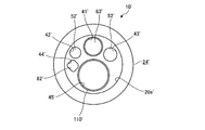
- FIG. 8 is a diagram showing the configuration of the support member 40.
- the support member 40 is formed in a substantially columnar shape as a whole having an outer diameter dimension slightly smaller than the inner diameter dimension of the through hole 20a.
- the support member 40 is formed with first to fifth recessed grooves 41 to 45 extending along the central axis Ax, respectively. These first to fifth concave grooves 41 to 45 correspond to the concave grooves according to the present invention.
- the first recessed groove 41 is located on the upper side of the support member 40 in FIG.
- the first concave groove 41 is configured as a groove by positioning a part of the circular hole to the outside of the support member 40.
- the portion of the tip side Ar1 of the observation optical member 60 is supported by the support member 40 in a state of being inserted into the first concave groove 41.
- the second and third concave grooves 42 and 43 are located on both the left and right sides of the support member 40 in FIG. 8 sandwiching the first concave groove 41. Similar to the first concave groove 41, the second and third concave grooves 42 and 43 are respectively configured as grooves by locating a part of the circular hole to the outside of the support member 40. ..
- the tip side Ar1 portion of the pair of illumination optical members 50 is supported by the support member 40 in a state of being inserted into the second and third recessed grooves 42 and 43, respectively.
- the fourth concave groove 44 is located on the lower side of the support member 40 with respect to the second concave groove 42 in FIG. Like the first concave groove 41, the fourth concave groove 44 is configured as a groove by positioning a part of the circular hole to the outside of the support member 40. The portion of Ar1 on the tip end side of the air supply / water supply member 80 is supported by the support member 40 in a state of being inserted into the fourth concave groove 44.
- the fifth concave groove 45 is located in the support member 40 at a position facing the first concave groove 41 with the central axis Ax interposed therebetween. Like the first concave groove 41, the fifth concave groove 45 is configured as a groove by positioning a part of the circular hole to the outside of the support member 40. The portion of Ar1 on the tip end side of the pipe 110 is supported by the support member 40 in a state of being inserted into the fifth concave groove 45.
- the wall portion between the first and fifth concave grooves 41 and 45 is cut out over the entire length of the support member 40. Therefore, the first and fifth recessed grooves 41 and 45 communicate with each other. Further, the portion where the second and fourth concave grooves 42 and 44 are formed and the portion where the third concave groove 43 is formed are separated from each other in a plane orthogonal to the central axis Ax. It corresponds to the first supports 40a and 40b (FIG. 8) according to the present invention, respectively. Further, as shown in FIG. 8, the two first supports 40a and 40b are integrated by the second support 40c at the proximal end side Ar2.
- the portion of the distal end side Ar1 of the observation optical member 60 and the portion of the distal end side Ar1 of the pipe 110 are supported by the support member 40 in a state of being sandwiched between the two first supports 40a and 40b. ..
- the support member 40 is inserted into the through hole 20a in the transducer 20 while supporting the structure 100.
- the structure 100 is positioned with respect to the transducer 20.
- the tips of the two first supports 40a and 40b are substantially flush with the tips of the tip member 24.
- the second support 40c is located outside the through hole 20a.
- the gap between the support member 40 (first to fifth concave grooves 41 to 45), the structure 100, and the inner surface of the through hole 20a is appropriately provided with an adhesive in order to ensure watertightness. Etc. are filled.
- the ultrasonic endoscope 2 according to the first embodiment is configured as a direct-view type endoscope that observes a direction along the central axis Ax.
- FIG. 9 and 10 are diagrams for explaining the effect of the first embodiment.
- FIG. 9 is a diagram corresponding to FIG. 4, and is a diagram showing a conventional configuration in which the structure 100 is supported by circular holes 41 ′ to 45 ′.
- a reference numeral in which "'" is added to the reference numeral of the corresponding member is used.
- the tip member 24'shown in FIG. 9 is indicated by a alternate long and short dash line.
- the portion of the support member 40'that supports the structure 100 is composed of circular holes 41'to 45'. That is, a wall thickness having a predetermined dimension is provided between the outer peripheral surface of the support member 40'and the inner surface of the circular holes 41' to 45'. Therefore, the diameter of the support member 40'cannot be reduced due to the size of the wall thickness.
- the support member 40 has first to fifth recesses extending along the central axis Ax. Grooves 41 to 45 are provided. Then, the structure 100 is supported by the support member 40 in a state of being inserted into the first to fifth recessed grooves 41 to 45.
- the support member 40 is inserted into the through hole 20a while supporting the structure 100. That is, by forming the portions (first to fifth concave grooves 41 to 45) of the support member 40 that support the structure 100 with the grooves, the outer peripheral surface of the support member 40 and the supporting portions (first to fifth). The size of the wall thickness between the fifth concave groove 41 to 45) is omitted. Therefore, the diameter of the support member 40 can be reduced, and the diameter of the intubation tube 6 can be reduced.
- the first and fifth concave grooves 41 and 45 communicate with each other. Therefore, the size of the wall thickness between the first and fifth recessed grooves 41 and 45 can be omitted, and the diameter of the intubation tube 6 can be further reduced.
- the pipe 110 is inserted into the fifth concave groove 45. That is, by providing the pipe 110 at a position corresponding to the treatment tool channel through which the treatment tool such as the puncture needle is inserted, even if the configuration is such that the fifth concave groove 45 is formed instead of the circular hole 45'. Sufficient watertightness can be ensured.
- FIG. 11 is a diagram showing the configuration of the tip unit 10A according to the second embodiment. Specifically, FIG. 11 is a diagram showing the tip of the tip unit 10A.
- FIG. 12 is a diagram showing the configuration of the image pickup lens 63A. Specifically, FIG. 12 is a view of the image pickup lens 63A viewed from a direction along the central axis Ax.
- the lens frame 632 has a shape different from that of the ultrasonic endoscope 2 described in the first embodiment described above. Different lens frames 632A are used.
- the lens frame 632A has a first protruding portion 633 and a second protruding portion 634 with respect to the lens frame 632 described in the first embodiment described above. Is added.
- the first protruding portion 633 is a portion that protrudes toward the inner surface of the through hole 20a, as shown in FIG. 11 or FIG.
- the tip of the first protruding portion 633 has a shape that follows the inner surface of the through hole 20a. That is, the outer surface of the image pickup lens 63A (lens frame 632A) facing the inner surface of the through hole 20a has a shape that follows the inner surface of the through hole 20a.
- the second protruding portion 634 is a portion protruding toward the pipe 110 as shown in FIG. 11 or FIG.
- the tip of the second protrusion 634 has a shape that follows the outer surface of the pipe 110. That is, the outer surface of the image pickup lens 63A (lens frame 632A) facing the pipe 110 has a shape that imitates the outer surface of the pipe 110.
- the outer surface of the image pickup lens 63A facing the inner surface of the through hole 20a has a shape that imitates the inner surface of the through hole 20a.
- the outer surface of the image pickup lens 63A facing the pipe 110 has a shape that imitates the outer surface of the pipe 110. That is, by forming the outer surface of the image pickup lens 63A into the shape described above, the adhesive that fills the gap between the image pickup lens 63A, the first concave groove 41, the inner surface of the through hole 20a, and the pipe 110. The amount can be reduced. Therefore, the resistance to the load of the chemical solution can be enhanced.
- the outer surface of the image pickup lens 63A has the shape described above, but the present invention is not limited to this. As long as the structure 100 is supported by the support member 40, the outer surface of the other structure 100 facing the inner surface of the through hole 20a may be shaped to imitate the inner surface of the through hole 20a. Further, in the first embodiment described above, the outer surface of the pipe 110 facing the image pickup lens 63 may be shaped to imitate the outer surface of the image pickup lens 63.
- FIG. 13 is a diagram showing a configuration of the tip unit 10B according to the third embodiment. Specifically, FIG. 13 is a diagram showing the tip of the tip unit 10B.
- FIG. 14 is a diagram showing the configuration of the tip member 24B. Specifically, FIG. 13 is a view of the tip member 24B viewed from the direction along the central axis Ax.
- the tip member 24 has a shape with respect to the ultrasonic endoscope 2 described in the above-described first embodiment. Different tip members 24B are used.
- the tip member 24B is provided with a pair of projecting portions 242 that project from the inner surface of the through hole 20a toward the pipe 110, respectively.
- Each tip of the pair of protrusions 242 has a shape that follows the outer surface of the pipe 110. That is, the inner surface of the through hole 20a facing the pipe 110 has a shape that follows the outer surface of the pipe 110.
- the pair of protrusions 242 may be provided only on the tip member 24B, or may be provided on both the tip member 24B and the tubular member 22 and extend over the entire length of the through hole 20a. ..
- the inner surface of the through hole 20a facing the pipe 110 has a shape that imitates the outer surface of the pipe 110. That is, by forming the inner surface of the through hole 20a into the shape described above, the amount of the adhesive to be filled in the gap between the pipe 110, the fifth concave groove 45, and the inner surface of the through hole 20a is reduced. Can be done. Therefore, the resistance to the load of the chemical solution can be enhanced.
- the inner surface of the through hole 20a facing the pipe 110 has the above-mentioned shape, but the present invention is not limited to this. As long as the structure 100 is supported by the support member 40, the inner surface of the through hole 20a facing the other structure 100 may be shaped to imitate the outer surface of the structure 100.
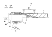
- FIG. 15 and 16 are views showing the configuration of the tip unit 10C according to the fourth embodiment.
- FIG. 15 is a side view of the tip unit 10C viewed from a direction orthogonal to the central axis Ax.
- FIG. 16 is a diagram showing the tip of the tip unit 10C.
- a cover member 120 is added to the ultrasonic endoscope 2 described in the above-described first embodiment. ing.
- the cover member 120 is a flat plate made of a translucent material, and covers the tip of the support member 40 by being attached to the tip of the tip member 24. As shown in FIG. 16, the cover member 120 is formed with holes 121 and 122 penetrating the front and back at a position corresponding to the air supply / water supply member 80 and a position corresponding to the pipe 110, respectively. That is, the fluid that has passed through the air supply / water supply member 80 is discharged from the hole 121 (nozzle 82) toward the position of the cover member 120 that faces the image pickup lens 63. Further, a treatment tool (not shown) such as a puncture needle via the pipe 110 projects outward from the hole 122.
- the ultrasonic endoscope 2C according to the fourth embodiment includes a cover member 120 that covers the tip of the support member 40. Therefore, in the gap between the adhesive exposed on the outer surface by the cover member 120 (support members 40 (first to fifth concave grooves 41 to 45), the structure 100, and the inner surface of the through hole 20a). The amount of the filled adhesive) can be reduced, and the resistance to the load of the chemical solution can be increased.
- the holes 121 and 122 are formed only at the positions corresponding to the nozzle 82 and the pipe 110, but the present invention is not limited to this, and the imaging lens 63 and the illumination lens 52 are not limited to this. It may be formed at a position corresponding to. That is, the image pickup lens 63 and the illumination lens 52 may or may not be covered with the cover member 120.
- the ultrasonic endoscopes 2 (2A to 2C) are not limited to the medical field, but are used as an endoscope system for observing the inside of a subject such as a mechanical structure in the industrial field. You may install it.
Landscapes
- Health & Medical Sciences (AREA)
- Life Sciences & Earth Sciences (AREA)
- Surgery (AREA)
- Engineering & Computer Science (AREA)
- Heart & Thoracic Surgery (AREA)
- Veterinary Medicine (AREA)
- Nuclear Medicine, Radiotherapy & Molecular Imaging (AREA)
- Pathology (AREA)
- Radiology & Medical Imaging (AREA)
- Biomedical Technology (AREA)
- Physics & Mathematics (AREA)
- Medical Informatics (AREA)
- Molecular Biology (AREA)
- Biophysics (AREA)
- Animal Behavior & Ethology (AREA)
- General Health & Medical Sciences (AREA)
- Public Health (AREA)
- Optics & Photonics (AREA)
- Mechanical Engineering (AREA)
- Gynecology & Obstetrics (AREA)
- Manufacturing & Machinery (AREA)
- Ultra Sonic Daignosis Equipment (AREA)
- Endoscopes (AREA)
Abstract
L'invention concerne un endoscope à ultrasons, pourvu d'un tube d'insertion 6 inséré dans un corps de sujet. Le tube d'insertion 6 est pourvu d'un transducteur 20 ayant une pluralité d'éléments piézoélectriques, chacun pour émettre des ondes ultrasonores et qui sont agencés le long d'une direction circonférentielle entourant le centre axial Ax du tube d'insertion 6, une structure 100 comprenant un élément optique d'observation 60 pour acquérir une image de sujet, et un élément de support 40 pour supporter la structure 100. Un trou traversant 20a qui pénètre le long de l'axe central Ax et dans lequel la structure 100 et l'élément de support 40 sont insérés est disposé dans le transducteur 20. Les première à cinquième rainures évidées 41-45 s'étendant le long de l'axe central Ax sont disposées dans l'élément de support 40. La structure 100 est supportée par l'élément de support 40 dans un état d'insertion dans les première à cinquième rainures évidées 41-45.
Priority Applications (3)
| Application Number | Priority Date | Filing Date | Title |
|---|---|---|---|
| JP2021506904A JP7155396B2 (ja) | 2019-03-19 | 2019-03-19 | 超音波内視鏡及び挿入管 |
| PCT/JP2019/011531 WO2020188762A1 (fr) | 2019-03-19 | 2019-03-19 | Endoscope à ultrasons |
| US17/400,652 US20210369239A1 (en) | 2019-03-19 | 2021-08-12 | Ultrasound endoscope and insertion tube |
Applications Claiming Priority (1)
| Application Number | Priority Date | Filing Date | Title |
|---|---|---|---|
| PCT/JP2019/011531 WO2020188762A1 (fr) | 2019-03-19 | 2019-03-19 | Endoscope à ultrasons |
Related Child Applications (1)
| Application Number | Title | Priority Date | Filing Date |
|---|---|---|---|
| US17/400,652 Continuation US20210369239A1 (en) | 2019-03-19 | 2021-08-12 | Ultrasound endoscope and insertion tube |
Publications (1)
| Publication Number | Publication Date |
|---|---|
| WO2020188762A1 true WO2020188762A1 (fr) | 2020-09-24 |
Family
ID=72519761
Family Applications (1)
| Application Number | Title | Priority Date | Filing Date |
|---|---|---|---|
| PCT/JP2019/011531 WO2020188762A1 (fr) | 2019-03-19 | 2019-03-19 | Endoscope à ultrasons |
Country Status (3)
| Country | Link |
|---|---|
| US (1) | US20210369239A1 (fr) |
| JP (1) | JP7155396B2 (fr) |
| WO (1) | WO2020188762A1 (fr) |
Citations (6)
| Publication number | Priority date | Publication date | Assignee | Title |
|---|---|---|---|---|
| JPS619423B2 (fr) * | 1981-06-17 | 1986-03-24 | Uiifuautomaaten Pikanooru Nv | |
| JPS62177701U (fr) * | 1986-05-01 | 1987-11-11 | ||
| WO2010150666A1 (fr) * | 2009-06-22 | 2010-12-29 | オリンパスメディカルシステムズ株式会社 | Gaine de rinçage d'endoscope |
| JP2011206416A (ja) * | 2010-03-30 | 2011-10-20 | Fujifilm Corp | 体腔内挿入型超音波検査装置 |
| JP2013248529A (ja) * | 2013-09-02 | 2013-12-12 | Olympus Corp | 内視鏡装置 |
| WO2014208218A1 (fr) * | 2013-06-25 | 2014-12-31 | オリンパスメディカルシステムズ株式会社 | Endoscope |
Family Cites Families (3)
| Publication number | Priority date | Publication date | Assignee | Title |
|---|---|---|---|---|
| JP3619423B2 (ja) | 2000-05-10 | 2005-02-09 | ペンタックス株式会社 | ラジアル走査前方視型超音波内視鏡 |
| EP1621135B1 (fr) * | 2004-07-29 | 2006-11-29 | Fujinon Corporation | Endoscope à ultrasons |
| US20090204006A1 (en) * | 2004-09-24 | 2009-08-13 | Katsuhiro Wakabayashi | Ultrasonic transducer, ultrasonic transducer array and ultrasonic endoscope system |
-
2019
- 2019-03-19 JP JP2021506904A patent/JP7155396B2/ja active Active
- 2019-03-19 WO PCT/JP2019/011531 patent/WO2020188762A1/fr active Application Filing
-
2021
- 2021-08-12 US US17/400,652 patent/US20210369239A1/en active Pending
Patent Citations (6)
| Publication number | Priority date | Publication date | Assignee | Title |
|---|---|---|---|---|
| JPS619423B2 (fr) * | 1981-06-17 | 1986-03-24 | Uiifuautomaaten Pikanooru Nv | |
| JPS62177701U (fr) * | 1986-05-01 | 1987-11-11 | ||
| WO2010150666A1 (fr) * | 2009-06-22 | 2010-12-29 | オリンパスメディカルシステムズ株式会社 | Gaine de rinçage d'endoscope |
| JP2011206416A (ja) * | 2010-03-30 | 2011-10-20 | Fujifilm Corp | 体腔内挿入型超音波検査装置 |
| WO2014208218A1 (fr) * | 2013-06-25 | 2014-12-31 | オリンパスメディカルシステムズ株式会社 | Endoscope |
| JP2013248529A (ja) * | 2013-09-02 | 2013-12-12 | Olympus Corp | 内視鏡装置 |
Also Published As
| Publication number | Publication date |
|---|---|
| JP7155396B2 (ja) | 2022-10-18 |
| JPWO2020188762A1 (fr) | 2020-09-24 |
| US20210369239A1 (en) | 2021-12-02 |
Similar Documents
| Publication | Publication Date | Title |
|---|---|---|
| US11317786B2 (en) | Endoscope | |
| WO2011108157A1 (fr) | Endoscope | |
| JP6588630B2 (ja) | 超音波振動子ユニット | |
| US11103220B2 (en) | Ultrasonic endoscope | |
| JPWO2018003737A1 (ja) | 超音波内視鏡 | |
| WO2017038152A1 (fr) | Connecteur d'endoscope | |
| US11903758B2 (en) | Ultrasonic endoscope | |
| US10869649B2 (en) | Ultrasound transducer module and ultrasound endoscope | |
| WO2020188762A1 (fr) | Endoscope à ultrasons | |
| US10987087B2 (en) | Ultrasound endoscope | |
| JP7249788B2 (ja) | 内視鏡 | |
| JP6697962B2 (ja) | 超音波振動子および超音波内視鏡 | |
| WO2018079792A1 (fr) | Endoscope | |
| JP6001230B2 (ja) | 超音波内視鏡、超音波観察装置および超音波内視鏡システム | |
| JP6103991B2 (ja) | 超音波探触子および超音波内視鏡システム | |
| JP4647968B2 (ja) | 超音波内視鏡 | |
| JP7223871B2 (ja) | 超音波内視鏡 | |
| JP7246539B2 (ja) | 内視鏡 | |
| JP4632748B2 (ja) | カプセル型医療装置 | |
| JP2004298240A (ja) | 超音波内視鏡 |
Legal Events
| Date | Code | Title | Description |
|---|---|---|---|
| 121 | Ep: the epo has been informed by wipo that ep was designated in this application |
Ref document number: 19919786 Country of ref document: EP Kind code of ref document: A1 |
|
| ENP | Entry into the national phase |
Ref document number: 2021506904 Country of ref document: JP Kind code of ref document: A |
|
| NENP | Non-entry into the national phase |
Ref country code: DE |
|
| 122 | Ep: pct application non-entry in european phase |
Ref document number: 19919786 Country of ref document: EP Kind code of ref document: A1 |