WO2020188699A1 - 受信装置、通信システム、プログラム及び受信方法 - Google Patents
受信装置、通信システム、プログラム及び受信方法 Download PDFInfo
- Publication number
- WO2020188699A1 WO2020188699A1 PCT/JP2019/011168 JP2019011168W WO2020188699A1 WO 2020188699 A1 WO2020188699 A1 WO 2020188699A1 JP 2019011168 W JP2019011168 W JP 2019011168W WO 2020188699 A1 WO2020188699 A1 WO 2020188699A1
- Authority
- WO
- WIPO (PCT)
- Prior art keywords
- interval
- time
- frame
- image
- display
- Prior art date
- Legal status (The legal status is an assumption and is not a legal conclusion. Google has not performed a legal analysis and makes no representation as to the accuracy of the status listed.)
- Ceased
Links
Images


Classifications
-
- H—ELECTRICITY
- H04—ELECTRIC COMMUNICATION TECHNIQUE
- H04N—PICTORIAL COMMUNICATION, e.g. TELEVISION
- H04N21/00—Selective content distribution, e.g. interactive television or video on demand [VOD]
- H04N21/40—Client devices specifically adapted for the reception of or interaction with content, e.g. set-top-box [STB]; Operations thereof
- H04N21/43—Processing of content or additional data, e.g. demultiplexing additional data from a digital video stream; Elementary client operations, e.g. monitoring of home network or synchronising decoder's clock; Client middleware
- H04N21/4302—Content synchronisation processes, e.g. decoder synchronisation
- H04N21/4305—Synchronising client clock from received content stream, e.g. locking decoder clock with encoder clock, extraction of the PCR packets
-
- H—ELECTRICITY
- H04—ELECTRIC COMMUNICATION TECHNIQUE
- H04N—PICTORIAL COMMUNICATION, e.g. TELEVISION
- H04N21/00—Selective content distribution, e.g. interactive television or video on demand [VOD]
- H04N21/40—Client devices specifically adapted for the reception of or interaction with content, e.g. set-top-box [STB]; Operations thereof
- H04N21/41—Structure of client; Structure of client peripherals
- H04N21/414—Specialised client platforms, e.g. receiver in car or embedded in a mobile appliance
- H04N21/41407—Specialised client platforms, e.g. receiver in car or embedded in a mobile appliance embedded in a portable device, e.g. video client on a mobile phone, PDA, laptop
-
- H—ELECTRICITY
- H04—ELECTRIC COMMUNICATION TECHNIQUE
- H04N—PICTORIAL COMMUNICATION, e.g. TELEVISION
- H04N5/00—Details of television systems
- H04N5/04—Synchronising
- H04N5/06—Generation of synchronising signals
Definitions
- the present invention relates to a receiving device, a communication system, a program and a receiving method.
- a synchronization process that matches the transmission time of the transmitting device with the display time of the receiving device in order to reduce the delay that occurs when transmitting the video signal.
- the synchronization process is executed using, for example, a time signal transmitted together with the video signal.
- the transmitted video signal is less likely to receive a large disturbance. Therefore, a simple synchronization process is sufficient.
- the signal path may contain a large disturbance.
- a PLL (Phase Locked Loop) circuit may be used to eliminate the influence of the disturbance. However, using the PLL circuit only for removing the influence of the disturbance causes an increase in cost. On the other hand, if the transmitting device and the receiving device are wirelessly connected and no synchronization processing is performed, the frequency and / or phase of the transmission time and the display time will differ due to disturbance, resulting in missing frames and an increase in display delay. Etc. may occur.
- the present invention has been made in view of the above problems, and an object of the present invention is to reduce the possibility of problems such as missing frames and an increase in display delay even if a disturbance occurs in a communication path. It is to provide a communication system.
- the receiving device sequentially receives image information transmitted by the transmitting device at a given first interval by wireless communication, and sequentially receives frame images based on the image information according to a display clock.
- a display unit that generates display time information that represents the time corresponding to the update time of the frame image while displaying, and a second interval that represents the interval at which the frame image is displayed based on the plurality of display time information. Is included, and a control unit that controls the update cycle of the frame image according to the display clock so that the second interval approaches the first interval.
- the image information includes the generation time information representing the time generated for each of the image information
- the control unit includes the plurality of image information.
- the first interval is calculated based on the generation time information included in each.
- the receiving device further includes a processing unit that performs processing for each received image information and generates processing time information according to the time of performing the processing.
- the control unit further controls the time from the time when the processing is performed to the time when the frame image is displayed to approach a predetermined value based on the processing time information and the display time information. To do.
- the processing unit is a decoder that decodes the encoded image information, and represents the time when the decoding of the image information is completed. Generate time information.
- the receiving unit further has a storage unit for storing at least a part of the image information in the nth frame and the n + 1th frame, and the receiving unit is the n + 1 frame.
- the storage unit updates the image information of the n-1th frame with the image information of the n + 1th frame, and the display unit is the nth frame stored by the storage unit. Display the frame image of.
- the time when the absolute value of the difference between the first interval and the second interval becomes larger than the first value is the first time.
- the update cycle is controlled by using the first interval and the second interval, and the time when the absolute value of the difference between the first interval and the second interval becomes smaller than the second value is the second.
- the update cycle is controlled by using the first interval, the second interval, the processing time information, and the display time information.
- the receiving device, the generation time information, and the image information are included in the transmitting device for transmitting each image to the receiving device.
- the frame image based on the image information according to the procedure of sequentially receiving the image information transmitted by the transmitting device at a given first interval by wireless communication and the display clock.
- the computer is made to execute a procedure of calculating the interval and controlling the update cycle of the frame image according to the display clock so that the second interval approaches the first interval.
- the transmission device sequentially receives the image information transmitted at a given first interval by wireless communication, and the frame is based on the image information according to the display clock.
- the step includes calculating the two intervals and controlling the update cycle of the frame image according to the display clock so that the second interval approaches the first interval.
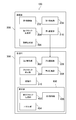
- FIG. 1 is a functional block diagram of the communication system 100 according to the present embodiment.
- the communication system 100 according to the present embodiment is a game system including, for example, a head-mounted display and a game machine that wirelessly transmits a video signal to the head-mounted display.
- the communication system 100 includes a transmission unit 200 and a reception unit 300.
- the transmission unit 200 transmits the generation time information and the image information to the reception unit 300 for each frame image.
- the receiving unit 300 sequentially receives the image information transmitted by the transmitting unit 200 at a given first interval by wireless communication.
- the transmission unit 200 includes a first control unit 202, a first clock generation unit 204, an image generation unit 206, a first processing unit 208, and a first communication unit 210.
- the receiving unit 300 includes a second control unit 302, a second clock generation unit 304, a second communication unit 306, a second processing unit 308, a storage unit 310, and a display unit 400.
- the first control unit 202 is, for example, a program control device such as a CPU that operates according to a program installed in a memory (not shown).
- the first control unit 202 controls the operation of each unit included in the transmission unit 200.
- the first clock generation unit 204 generates the first clock used by the first communication unit 210.
- the first clock generation unit 204 is an oscillation circuit including a crystal oscillator, and generates a first clock having a given frequency.
- the first clock generation unit 204 may generate clocks used in other units included in the transmission unit 200.
- the image generation unit 206 generates a frame image. Specifically, for example, the image generation unit 206 generates a number of image information per second according to the frequency of updating the frame image (hereinafter referred to as the frame frequency). For example, when the frame frequency is 120 Hz, the image generation unit 206 generates 120 image information every second.
- the image information includes the generation time information representing the time when the image information was generated for each of the image information.
- the image information includes generation time information called PTS (presentation time stamp).
- the first processing unit 208 performs processing for each image information generated by the image generation unit 206.
- the processing is, for example, modulation or compression.
- the first processing unit 208 is an encoder and compresses image information.
- the transmitting unit 200 can transmit a number of image information corresponding to the frame frequency to the receiving unit 300 every second.
- the first processing unit 208 may be omitted.
- the first communication unit 210 transmits image information at a given first interval by wireless communication using the first clock. Specifically, the first communication unit 210 transmits the image information compressed or modulated by the first processing unit 208 to the receiving unit 300 according to a given wireless communication standard.
- a given wireless communication standard may be any communication standard as long as a communication speed capable of transmitting a number of image information corresponding to a frame frequency per second is secured.
- the second control unit 302 is a program control device such as a CPU that operates according to a program installed in the storage unit 310.
- the second control unit 302 controls the operation of each unit included in the receiving unit 300.
- the second control unit 302 calculates the second interval representing the interval at which the frame image is displayed based on the plurality of display time information, and sets the display clock so that the second interval approaches the first interval. Controls the update cycle of the corresponding frame image.
- the second control unit 302 further controls the time from the processing time to the time when the frame image is displayed to approach a predetermined value based on the processing time information and the display time information. You may. Specific control will be described later.
- the second clock generation unit 304 generates the second clock used in each unit included in the reception unit 300.
- the second clock generation unit 304 is an oscillation circuit including a crystal oscillator, and generates a second clock having a given frequency.
- the first clock generation unit 204 and the second clock generation unit 304 are configured so that the frequencies of the first clock and the second clock are the same in design. However, even if the specifications of the parts included in the first clock generation unit 204 and the second clock generation unit 304 are the same, there is an error in the characteristics of each part. Further, the transmitting unit 200 and the receiving unit 300 are structurally separated and are placed in different environments (for example, temperature). In this case, since the characteristics of the same component included in the first clock generation unit 204 and the second clock generation unit 304 are different, the frequencies of the first clock and the second clock are usually different.
- the second communication unit 306 receives the image information at a given second interval by wireless communication using the second clock. Specifically, the second communication unit 306 receives image information from the first communication unit 210 in accordance with the above wireless communication standard.
- the first interval which is the interval at which the first communication unit 210 transmits the image information
- the second interval which is the interval at which the second communication unit 306 receives the image information
- the communication may be affected by disturbance.
- the first clock used by the first communication unit 210 and the second clock used by the second communication unit 306 may be different from each other. Therefore, the first interval and the second interval are usually different. The difference causes problems such as missing frames and an increase in display delay.
- the second processing unit 308 performs processing for each received image information and generates processing time information according to the time when the processing is performed.
- the processing is, for example, demodulation or decompression.
- the second processing unit 308 is a decoder that decodes the encoded image information, and generates processing time information that represents the time when the decoding of the image information is completed.
- the display unit 400 can display the frame image based on the image information.
- the second processing unit 308 may be omitted.
- the processing time information may be information representing the time when the second communication unit receives the image information.
- the storage unit 310 is a storage element such as a ROM or RAM, a hard disk drive, or the like.
- the storage unit 310 stores a program or the like executed by the second control unit 302.
- the storage unit 310 stores at least a part of the image information of the nth frame and the n + 1th frame, respectively. Then, when the second communication unit 306 receives the image information in the n + 1th frame, the storage unit 310 updates the image information in the n-1th frame with the image information in the n + 1th frame. Specifically, for example, first, when the second communication unit 306 receives the image information of the first frame, the storage unit 310 stores the image information of the first frame. Next, when the second communication unit 306 receives the image information of the second frame, the storage unit 310 stores the image information of the second frame.
- the storage unit 310 when the second communication unit 306 receives the image information of the third frame, the storage unit 310 overwrites and stores the image information of the third frame in the area where the image information of the first frame is stored. To do. After that, when the second communication unit 306 receives the image information of the nth frame, the image information of the nth frame is overwritten and stored in the area where the image information of the n-2nd frame is stored. As a result, the storage unit 310 stores image information for two frames. The storage unit 310 functions as a buffer by rewriting the image information in the nth frame and at the same time reading the image information in the n + 1th frame to the display unit 400.
- the display unit 400 sequentially displays frame images based on the image information according to the display clock, and generates display time information indicating the time corresponding to the update time of the frame image.
- the display unit 400 is a display device such as a liquid crystal display device or an organic EL display device.
- the display unit 400 includes a display clock generation unit 402, a panel unit 404, and a third control unit 406.
- the display unit 400 displays the frame image of the nth frame stored by the storage unit 310 when the second communication unit 306 receives the image information of the n + 1th frame.
- the display clock generation unit 402 generates a display clock. Specifically, for example, the display clock generation unit 402 generates the display clock used by the panel unit 404 based on the control amount C generated by the second clock and the second control unit 302.
- the panel unit 404 is a glass substrate or a resin substrate on which an electronic circuit necessary for display is formed.
- the panel unit 404 displays the frame image of the nth frame stored in the storage unit 310 according to the instruction of the third control unit 406.
- the third control unit 406 is a device that controls the operation of each unit of the display unit 400. Specifically, for example, the third control unit 406 controls the update cycle of the frame image based on the control amount C generated by the second control unit 302.
- the update cycle is controlled by changing the frequency of the display clock or the return period. Specifically, when the update cycle is shortened, the third control unit 406 controls so that the frequency of the display clock is increased or the return line period is shortened. On the other hand, when the update cycle is lengthened, the third control unit 406 controls so as to lower the frequency of the display clock or lengthen the blanking interval.
- FIG. 2 is a diagram for explaining the calculation of the control amount C.
- FIG. 3 is a diagram showing the relationship between the display time, the processing completion time, and the image information generation time.
- the characters surrounded by the square frame included in FIG. 3 indicate the order of the frames.
- the display time represents the time when each frame started.
- the processing completion time represents the time when the second processing unit 308 completes the processing.
- the image generation time represents the time when the image generation unit 206 generates the image information.
- the display time represents the time when each frame starts, but may represent the time when the display is completed or the time when a predetermined time has elapsed since the display was started.
- the processing completion time may not be the time when the processing is completed, but may be the time when the processing is started or the time when the second communication unit 306 completes the reception of the image information.
- the storage unit 310 stores at least a part of the frame image information of the n-1th frame and the nth frame
- the second communication unit 306 stores the image information of the n + 1th frame. Explain that it is in the process of receiving.
- the second control unit 302 calculates the first interval. Specifically, for example, the second control unit 302 calculates the first interval based on the generation time information included in each of the plurality of image information.
- the second control unit 302 starts from the time represented by the generation time information (PTS (n)) included in the image information in the nth frame to the generation time information (PTS (n-1)) included in the image information in the n-1th frame. ) Is subtracted.
- the second control unit 302 acquires the subtracted value as the first interval (D_SrcTS).
- the first interval (D_SrcTS) is the image information of a certain frame. This is the interval between the generated time and the time when the image information of the next frame is generated.
- the second control unit 302 calculates the second interval. Specifically, for example, the second control unit 302 calculates the second interval based on a plurality of display time information.
- the second control unit 302 has a time represented by the generation time information (DispTS (n-1)) included in the image information of the n-1th frame from the time represented by the display time information (DispTS (n)) of the nth frame. Is subtracted.
- the second control unit 302 acquires the deducted value as the second interval (D_DispTS).
- the display time information is, for example, a vertical synchronization signal acquired from the display unit 400 by the second control unit 302.
- the vertical synchronization signal is a signal having a period of displaying one frame image, and is, for example, a signal including one pulse in one cycle.
- the second control unit 302 acquires the second interval (D_DispTS) by subtracting the time when the vertical synchronization signal of the n-1th frame is acquired from the time when the vertical synchronization signal of the nth frame is acquired.
- the second interval (D_DispTS) is the interval between the time when the display of the nth frame is started and the time when the display of the n + 1th frame is started.
- the second control unit 302 calculates the coefficient F (D_SrcTS-DispTS) by subtracting the second interval from the first interval.
- the coefficient F is information representing a deviation between the time interval in which the image information is generated and the time interval in which the display is actually performed based on the image information. That is, the coefficient F is information representing a frequency shift.
- the time for calculating the first interval and the second interval does not have to be synchronized with the time when the display unit 400 updates the frame image. Further, it is desirable that the second control unit 302 calculates the first interval and the second interval a plurality of times in one frame period. Specifically, when the ideal frame update frequency of the display unit 400 is 120 Hz, the period for which the display unit 400 updates the frame image is approximately 8.33 ms. On the other hand, the generation time information is generated at, for example, 90 kHz. In this case, the second control unit 302 may calculate the first interval and the second interval at 90 kHz.
- the interval (D_SrcTS + jitter) between the processing completion times of the nth frame and the n + 1th frame usually includes an indefinite component (jitter) due to the influence of disturbance or the like. .. Since the display unit 400 sequentially displays the frame images based on the image information, the second interval is not constant when the processing completion time is different for each frame.
- the second control unit 302 may process so that the second interval (D_DispTS) falls within a predetermined range. Specifically, when the second interval (D_DispTS) is smaller than the set lower limit value, the second control unit 302 sets the second interval (D_DispTS) as the lower limit value and sets the second interval (D_DispTS). If is a value larger than the set upper limit value, the second interval (D_DispTS) may be set as the upper limit value. For example, when the ideal frame update frequency of the display unit 400 is 120 Hz, the lower limit value is set to 8.00 ms and the upper limit value is set to 8.66 ms.
- the second control unit 302 may perform a process of smoothing the second interval (D_DispTS). For example, the second control unit 302 may calculate the moving average of the second interval (D_DispTS) calculated in the period of 8.33 ms.
- the second control unit 302 calculates the third interval (Raw_Ph). Specifically, for example, the second control unit 302 calculates the third interval in the nth frame based on the time when the processing by the second processing unit 308 is completed and the display time information. The second control unit 302 subtracts the time represented by the time when the processing of the nth frame is completed (DecTS (n)) from the time represented by the display time information (DispTS (n)) of the nth frame. The second control unit 302 acquires the deducted value as the third interval (Raw_Ph).
- the smoothed third interval (Raw_Ph) will be referred to as a third interval (Phase).
- the third interval (Phase) is an interval between the time when the processing of the nth frame is completed and the time when the display of the frame image is started based on the image information of the nth frame. ..
- the second control unit 302 subtracts the target value (Target) of the time required from the time when the processing is performed to the time when the display of the frame image is started from the third interval (Phase), and subtracts the coefficient P ( Phase-Target) is calculated.
- the target value (Target) is a value set as the time required from the time when the processing is performed to the time when the display of the frame image is started in an ideal environment. That is, the coefficient P is information representing the difference between the actually required time and the ideal time from the time when the processing is performed to the time when the display of the frame image is started. That is, the coefficient P is information representing the phase shift.
- the first interval and the second interval match and do not change with time.
- the third interval is also constant. Therefore, after the second processing unit 308 processes the image information in the nth frame, the time until the image information in the nth frame is stored in the storage unit 310 and the display by the display unit 400 is started is constant. Is. In this case, the coefficient P is 0.
- the coefficient P calculated by subtracting the target value (Target) from the third interval is usually not 0.
- the second control unit 302 sets the first interval and the second interval when the absolute value of the difference between the first interval and the second interval becomes larger than the first value for the first time or more. Use to control the update cycle. Further, the second control unit 302 sets the first interval and the second interval when the absolute value of the difference between the first interval and the second interval becomes smaller than the second value for the second time or longer.
- the update cycle is controlled by using the processing time information and the display time information. That is, the second control unit 302 divides the case into two states according to the magnitudes of the coefficient F and the coefficient P, and the control amount C for controlling the update cycle of the frame image by a different method according to the state. Is calculated.
- the two states will be described with reference to the state transition diagram shown in FIG.
- the initial state is the first state in which control is performed only by the coefficient F.
- the second state is a state in which control is performed by the coefficient F and the coefficient P.
- the first state is a state in which there is a large discrepancy between the time interval in which the image information is generated and the time interval in which the display is actually performed based on the image information. Therefore, it is necessary to change the update cycle of the frame image significantly.
- the second control unit 302 calculates the control amount C according to the equation 1.
- the function f 0 of the equation 1 is a function that outputs a value proportional to the absolute value of the coefficient F.
- the control amount C does not include the component P related to the phase.
- the second state is a state in which the difference between the time interval in which the image information is generated and the time interval in which the display is actually performed based on the image information is small. Therefore, it is not necessary to change the update cycle of the frame image significantly.
- the second control unit 302 calculates the control amount C according to Equation 2.
- the function f 1 of Equation 2 is a function that outputs a value proportional to the absolute value of the coefficient P.
- the second control unit 302 controls the update cycle of the frame image using the control amount C. Specifically, the second control unit 302 changes the update cycle of the current frame image by the control amount C. That is, if the control amount C is a positive value, the second control unit 302 lengthens the frame image update cycle (that is, reduces the frame image update frequency). On the other hand, if the control amount C is a negative value, the second control unit 302 shortens the frame image update cycle (that is, increases the frame image update frequency).
- the first state is a state in which the above deviation is large, and it is necessary to control the frequency before matching the phases. Therefore, in the first state, a coefficient F larger than that in the second state is calculated based on Equation 1. Therefore, in the first state, the update cycle of the frame image is changed more than in the second state.
- the second state is a state in which the deviation is small, and it is necessary to control the phase. Therefore, the update cycle of the frame image is controlled so that the coefficient P approaches the target value (Target) based on the equation 2 indicating that the component of the coefficient P is included in the control amount C.
- Equation 2 also includes a component with a coefficient F.
- the second control unit 302 can not only control the update cycle of the frame image so that the phases are aligned based on the coefficient P, but also prevent the frequency from being significantly deviated based on the coefficient F. By repeating the above control, the coefficient F and the coefficient P are controlled to be small.
- the second control unit 302 converts the control amount C into a format that can be recognized by the display unit 400, and then transmits the converted signal to the display unit 400.
- the display unit 400 changes the update cycle of the frame image by changing the frequency of the display clock and the length of the blanking interval according to the signal. As described above, the second control unit 302 controls the update cycle of the frame image so that the second interval approaches the first interval.
- the second control unit 302 may use the coefficient F to control the frequency of the display clock and the coefficient P to control the length of the blanking interval.
- the coefficient F is information that reflects the deviation between the frequency at which the image information is generated and the update frequency of the frame image.
- the coefficient P is information that reflects the difference between the time when the image information is generated and the time when the display of the frame image is started. That is, the coefficient F is information representing a frequency shift, and the coefficient P is information representing a phase shift. Therefore, the second control unit 302 may control the frequency of the display clock by using the coefficient F representing the frequency shift, and control the length of the blanking interval by using the coefficient P representing the phase shift. With this control, the possibility of missing frames and an increase in display delay can be further reduced.
Landscapes
- Engineering & Computer Science (AREA)
- Multimedia (AREA)
- Signal Processing (AREA)
- General Engineering & Computer Science (AREA)
- Control Of Indicators Other Than Cathode Ray Tubes (AREA)
Abstract
通信経路に外乱が生じても、フレームの欠落や表示の遅延増加等の不具合が生じる可能性を低減する。 受信装置であって、送信装置が所与の第1間隔で送信する画像情報を無線通信によって順次受信する受信部と、表示クロックに従って、前記画像情報に基づいてフレーム画像を順次表示するとともに、前記フレーム画像の更新時刻に応じた時刻を表す表示時刻情報を生成する表示部と、複数の前記表示時刻情報に基づいて前記フレーム画像の表示が行われた間隔を表す第2間隔を算出し、前記第2間隔が前記第1間隔に近づくように、前記表示クロックに応じた前記フレーム画像の更新周期を制御する制御部と、を含む。
Description
本発明は、受信装置、通信システム、プログラム及び受信方法に関する。
一般的に、送信装置と受信装置との間で映像信号の送受信を行う場合、映像信号を伝送する際に生じる遅延を低減するため、送信装置の送信時刻と受信装置の表示時刻と合わせる同期処理が実施される。同期処理は、例えば、映像信号とともに送信される時刻信号を用いて実行される。
送信装置と受信装置とが有線で接続される場合、送信される映像信号は大きな外乱を受けるおそれが小さい。そのため、簡易な同期処理で十分である。しかし、送信装置と受信装置とが無線で接続される場合、信号経路に大きな外乱が含まれる可能性がある。
当該外乱による影響を除去するため、PLL(Phase Locked Loop)回路が用いられることがある。しかしながら、当該外乱による影響を取り除くためだけにPLL回路を用いることはコストアップの要因となる。一方、送信装置と受信装置とが無線で接続される場合に何ら同期処理が行われないと、外乱によって送信時刻と表示時刻の周波数及びまたは位相に差異が生じ、フレームの欠落や表示遅延の増加等が生じるおそれがある。
本発明は、上記問題点に鑑みてなされたものであり、その目的は、通信経路に外乱が生じても、フレームの欠落や表示遅延の増加等の不具合が生じる可能性を低減する受信装置及び通信システムを提供することである。
本発明の一側面に係る受信装置は、送信装置が所与の第1間隔で送信する画像情報を無線通信によって順次受信する受信部と、表示クロックに従って、前記画像情報に基づいてフレーム画像を順次表示するとともに、前記フレーム画像の更新時刻に応じた時刻を表す表示時刻情報を生成する表示部と、複数の前記表示時刻情報に基づいて前記フレーム画像の表示が行われた間隔を表す第2間隔を算出し、前記第2間隔が前記第1間隔に近づくように、前記表示クロックに応じた前記フレーム画像の更新周期を制御する制御部と、を含む。
また、本発明の他の一側面に係る受信装置によれば、前記画像情報は、前記画像情報毎に生成された時刻を表す生成時刻情報を含み、前記制御部は、複数の前記画像情報にそれぞれ含まれる前記生成時刻情報に基づいて、前記第1間隔を算出する。
また、本発明の他の一側面に係る受信装置によれば、さらに、受信した前記画像情報毎に処理を施すとともに、該処理を施す時刻に応じた処理時刻情報を生成する処理部を有し、前記制御部は、さらに、前記処理時刻情報と前記表示時刻情報とに基づいて、前記処理が施された時刻から前記フレーム画像が表示された時刻までの時間が所定の値に近づくように制御する。
また、本発明の他の一側面に係る受信装置によれば、前記処理部は、エンコードされた前記画像情報をデコードするデコーダであって、前記画像情報のデコードを完了させた時刻を表す前記処理時刻情報を生成する。
また、本発明の他の一側面に係る受信装置によれば、さらに、nフレーム目及びn+1フレーム目の前記画像情報のそれぞれ少なくとも一部を記憶する記憶部を有し、前記受信部がn+1フレーム目の前記画像情報を受信した時に、前記記憶部は、n-1フレーム目の前記画像情報をn+1フレーム目の前記画像情報に更新し、前記表示部は、前記記憶部が記憶したnフレーム目のフレーム画像を表示する。
また、本発明の他の一側面に係る受信装置によれば、前記制御部は、前記第1間隔と前記第2間隔の差分の絶対値が第1の値より大きくなる時間が第1の時間以上続いた場合に、前記第1間隔及び前記第2間隔を用いて前記更新周期を制御し、前記第1間隔と前記第2間隔の差分の絶対値が第2の値より小さくなる時間が第2の時間以上続いた場合に、前記第1間隔と、前記第2間隔と、前記処理時刻情報と、前記表示時刻情報と、を用いて前記更新周期を制御する。
また、本発明の一側面に係る通信システムによれば、受信装置と、前記生成時刻情報と、前記画像情報と、を画像毎に前記受信装置に送信する送信装置と、を含む。
また、本発明の一側面に係るプログラムによれば、送信装置が所与の第1間隔で送信する画像情報を無線通信によって順次受信する手順と、表示クロックに従って、前記画像情報に基づいてフレーム画像を順次表示するとともに、前記フレーム画像の更新時刻に応じた時刻を表す表示時刻情報を生成する手順と、複数の前記表示時刻情報に基づいて前記フレーム画像の表示が行われた間隔を表す第2間隔を算出し、前記第2間隔が前記第1間隔に近づくように、前記表示クロックに応じた前記フレーム画像の更新周期を制御する手順と、をコンピュータに実行させる。
また、本発明の一側面に係る受信方法によれば、送信装置が所与の第1間隔で送信する画像情報を無線通信によって順次受信するステップと、表示クロックに従って、前記画像情報に基づいてフレーム画像を順次表示するとともに、前記フレーム画像の更新時刻に応じた時刻を表す表示時刻情報を生成するステップと、複数の前記表示時刻情報に基づいて前記フレーム画像の表示が行われた間隔を表す第2間隔を算出し、前記第2間隔が前記第1間隔に近づくように、前記表示クロックに応じた前記フレーム画像の更新周期を制御するステップと、を含む。
以下、本発明の一実施形態について図面に基づき詳細に説明する。図1は、本実施形態に係る通信システム100の機能ブロック図である。本実施形態に係る通信システム100は、例えば、ヘッドマウントディスプレイと、当該ヘッドマウントディスプレイに対して無線で映像信号を送信するゲーム機と、を含むゲームシステムである。
図1に示すように、通信システム100は、送信部200と、受信部300と、を含む。送信部200は、生成時刻情報と、画像情報と、をフレーム画像毎に受信部300に送信する。受信部300は、送信部200が所与の第1間隔で送信する画像情報を無線通信によって順次受信する。
また、送信部200は、第1制御部202と、第1クロック生成部204と、画像生成部206と、第1処理部208と、第1通信部210と、を含む。また、受信部300は、第2制御部302と、第2クロック生成部304と、第2通信部306と、第2処理部308と、記憶部310と、表示部400と、を含む。
第1制御部202は、例えば図示しないメモリにインストールされるプログラムに従って動作するCPU等のプログラム制御デバイスである。第1制御部202は、送信部200に含まれる各部の動作を制御する。
第1クロック生成部204は、第1通信部210で用いられる第1クロックを生成する。具体的には、例えば、第1クロック生成部204は、水晶発振子を含む発振回路であり、所与の周波数である第1クロックを生成する。なお、第1クロック生成部204は、送信部200に含まれる他の各部で用いられるクロックを生成してもよい。
画像生成部206は、フレーム画像を生成する。具体的には、例えば、画像生成部206は、フレーム画像を更新する頻度(以下、フレーム周波数とする)に応じた数の画像情報を毎秒生成する。例えば、フレーム周波数が120Hzである場合、画像生成部206は、1秒ごとに120個の画像情報を生成する。
ここで、画像情報は、当該画像情報毎に当該画像情報が生成された時刻を表す生成時刻情報を含むことが望ましい。例えば、画像情報がMPEG-4規格に適合する情報である場合、画像情報は、PTS(presentation time stamp)と呼ばれる生成時刻情報を含む。
第1処理部208は、画像生成部206が生成した画像情報毎に処理を施す。処理は、例えば、変調または圧縮である。具体的には、例えば、第1処理部208はエンコーダであって、画像情報を圧縮する。第1処理部208が画像情報を変調または圧縮することにより、送信部200は、フレーム周波数に応じた数の画像情報を受信部300に毎秒送信できる。なお、画像情報に処理を施さずに送信する場合、第1処理部208は省略されてもよい。
第1通信部210は、第1クロックを用いた無線通信によって、所与の第1間隔で画像情報を送信する。具体的には、第1通信部210は、所与の無線通信規格に従って、第1処理部208で圧縮または変調された画像情報を受信部300に送信する。所与の無線通信規格は、フレーム周波数に応じた数の画像情報を毎秒送信できる通信速度が確保されていれば、どのような通信規格であってもよい。
第2制御部302は、記憶部310にインストールされるプログラムに従って動作するCPU等のプログラム制御デバイスである。第2制御部302は、受信部300に含まれる各部の動作を制御する。
また、第2制御部302は、複数の表示時刻情報に基づいてフレーム画像の表示が行われた間隔を表す第2間隔を算出し、第2間隔が第1間隔に近づくように、表示クロックに応じたフレーム画像の更新周期を制御する。ここで、第2制御部302は、さらに、処理時刻情報と表示時刻情報とに基づいて、処理が施された時刻からフレーム画像が表示された時刻までの時間が所定の値に近づくように制御してもよい。具体的な制御については後述する。
第2クロック生成部304は、受信部300に含まれる各部で用いられる第2クロックを生成する。具体的には、例えば、第2クロック生成部304は、水晶発振子を含む発振回路であり、所与の周波数である第2クロックを生成する。
ここで、第1クロック生成部204及び第2クロック生成部304は、第1クロックと第2クロックの周波数が設計上同じ周波数となるように構成される。しかしながら、第1クロック生成部204及び第2クロック生成部304に含まれる各部品の仕様が同一であっても、各部品の特性には誤差が存在する。また、送信部200と受信部300は、構造上分離されており置かれた環境(例えば温度など)が異なる。この場合、第1クロック生成部204及び第2クロック生成部304に含まれる同一の部品の特性が相違するため、第1クロックと第2クロックの周波数は相違するのが通常である。
第2通信部306は、第2クロックを用いた無線通信によって、所与の第2間隔で画像情報を受信する。具体的には、第2通信部306は、上記無線通信規格に従って、第1通信部210から画像情報を受信する。
ここで、第1通信部210が画像情報を送信する間隔である第1間隔と、第2通信部306が画像情報を受信する間隔である第2間隔は、同一となることが望ましい。しかしながら、第1通信部210と第2通信部306は無線通信によって通信を行うため、当該通信は外乱の影響を受けるおそれがある。また、上記のように、第1通信部210で用いられる第1クロックと、第2通信部306で用いられる第2クロックは、相違するおそれがある。従って、第1間隔と第2間隔は相違することが通常である。当該相違は、フレームの欠落や表示遅延の増加等の不具合の原因となる。
第2処理部308は、受信した画像情報毎に処理を施すとともに、該処理を施す時刻に応じた処理時刻情報を生成する。処理は、例えば、復調または伸張である。具体的には、例えば、第2処理部308は、エンコードされた画像情報をデコードするデコーダであって、画像情報のデコードを完了させた時刻を表す処理時刻情報を生成する。第2処理部308が画像情報に処理を施すことにより、表示部400は、画像情報に基づいてフレーム画像を表示できる。
なお、画像情報が処理を施されずに送信される場合、第2処理部308は省略されてもよい。この場合、処理時刻情報は、第2通信部が画像情報を受信した時刻を表す情報であってもよい。
記憶部310は、ROMやRAM等の記憶素子やハードディスクドライブなどである。記憶部310は、第2制御部302によって実行されるプログラムなどを記憶する。
また、記憶部310は、nフレーム目及びn+1フレーム目の画像情報のそれぞれ少なくとも一部を記憶する。そして、記憶部310は、第2通信部306がn+1フレーム目の画像情報を受信した時に、n-1フレーム目の画像情報をn+1フレーム目の画像情報に更新する。具体的には、例えば、まず、第2通信部306が1フレーム目の画像情報を受信した時に、記憶部310は、1フレーム目の画像情報を記憶する。次に、第2通信部306が2フレーム目の画像情報を受信した時に、記憶部310は、2フレーム目の画像情報を記憶する。さらに、第2通信部306が3フレーム目の画像情報を受信した時に、記憶部310は、1フレーム目の画像情報が記憶されている領域に、3フレーム目の画像情報を上書して記憶する。以降、第2通信部306がnフレーム目の画像情報を受信したときに、n-2フレーム目の画像情報が記憶されている領域に、nフレーム目の画像情報を上書して記憶する。これにより、記憶部310は2フレーム分の画像情報を記憶する。記憶部310は、nフレーム目の画像情報が書き換えられると同時に、n+1フレーム目の画像情報が表示部400に読み出されることによって、バッファとしての機能を果たす。
表示部400は、表示クロックに従って、画像情報に基づいてフレーム画像を順次表示するとともに、フレーム画像の更新時刻に応じた時刻を表す表示時刻情報を生成する。具体的には、例えば、表示部400は、液晶表示装置や有機EL表示装置等の表示装置である。
表示部400は、表示クロック生成部402と、パネル部404と、第3制御部406と、を有する。表示部400は、第2通信部306がn+1フレーム目の画像情報を受信した時に、記憶部310が記憶したnフレーム目のフレーム画像を表示する。
表示クロック生成部402は、表示クロックを生成する。具体的には、例えば、表示クロック生成部402は、第2クロック及び第2制御部302が生成する制御量Cに基づいて、パネル部404が用いる表示クロックを生成する。
パネル部404は、表示に必要な電子回路が形成されたガラス基板や樹脂基板である。パネル部404は、第3制御部406の指示に従って、記憶部310が記憶しているnフレーム目のフレーム画像を表示する。
第3制御部406は、表示部400の各部の動作を制御するデバイスである。具体的には、例えば、第3制御部406は、第2制御部302が生成した制御量Cに基づいて、フレーム画像の更新周期を制御する。
更新周期は、表示クロックの周波数または帰線期間が変更されることによって制御される。具体的には、更新周期を短くする場合、第3制御部406は、表示クロックの周波数を上げる、または、帰線期間が短くなるように制御する。一方、更新周期を長くする場合、第3制御部406は、表示クロックの周波数を下げる、または、帰線期間を長くするように制御する。
続いて、第2制御部302による制御量Cの生成について説明する。図2は、制御量Cの算出について説明するための図である。また、図3は、表示時刻、処理完了時刻及び画像情報生成時刻の関係を示す図である。図3に含まれる四角い枠に囲まれた文字はフレームの順番を表す。表示時刻は、各フレームが開始した時刻を表す。処理完了時刻は、第2処理部308が処理を完了した時刻を表す。映像生成時刻は、画像生成部206が画像情報を生成した時刻を表す。
なお、図3では、表示時刻は、各フレームが開始した時刻を表すが表示が完了した時刻や、表示が開始されてから所定の時間が経過した時刻を表してもよい。また、処理完了時刻は、処理が完了した時刻ではなく、処理を開始した時刻や、第2通信部306が画像情報の受信を完了した時刻であってもよい。
なお、以下具体例として、記憶部310がn-1フレーム目及びnフレーム目のフレーム画像情報のそれぞれ少なくとも一部を記憶した状態であって、第2通信部306がn+1フレーム目の画像情報を受信している途上であるとして説明する。
まず、第2制御部302は、第1間隔を算出する。具体的には、例えば、第2制御部302は、複数の画像情報にそれぞれ含まれる生成時刻情報に基づいて、第1間隔を算出する。第2制御部302は、nフレーム目の画像情報に含まれる生成時刻情報(PTS(n))が表す時刻から、n-1フレーム目の画像情報に含まれる生成時刻情報(PTS(n-1)が表す時刻を差し引く。第2制御部302は、当該差し引いた値を第1間隔(D_SrcTS)として取得する。図3に示すように、第1間隔(D_SrcTS)は、あるフレームの画像情報が生成された時刻とその次のフレームの画像情報が生成された時刻との間隔である。
次に、第2制御部302は、第2間隔を算出する。具体的には、例えば、第2制御部302は、複数の表示時刻情報に基づいて、第2間隔を算出する。第2制御部302は、nフレーム目の表示時刻情報(DispTS(n))が表す時刻から、n-1フレーム目の画像情報に含まれる生成時刻情報(DispTS(n-1))が表す時刻を差し引く。第2制御部302は、当該差し引いた値を第2間隔(D_DispTS)として取得する。
表示時刻情報は、例えば、第2制御部302が表示部400から取得する垂直同期信号である。垂直同期信号は、1個のフレーム画像を表示する期間を周期とする信号であって、例えば、1周期に1個のパルスを含む信号である。第2制御部302は、nフレーム目の垂直同期信号を取得した時刻から、n-1フレーム目の垂直同期信号を取得した時刻を差し引くことで第2間隔(D_DispTS)を取得する。図3に示すように、第2間隔(D_DispTS)は、nフレーム目の表示が開始された時刻と、n+1フレーム目の表示が開始された時刻と、の間隔である。
そして、第2制御部302は、第1間隔から第2間隔を差し引いて係数F(D_SrcTS-DispTS)を算出する。係数Fは、画像情報が生成された時間間隔と、当該画像情報に基づいて実際に行われた表示の時間間隔とのずれを表す情報である。すなわち、係数Fは、周波数のずれを表す情報である。
なお、第1間隔及び第2間隔を算出する時刻は、表示部400がフレーム画像を更新する時刻と同期していなくてもよい。また、第2制御部302は、1フレーム期間に、第1間隔及び第2間隔を複数回算出することが望ましい。具体的には、表示部400の理想的なフレーム更新周波数が120Hzである場合、表示部400がフレーム画像を更新する周期はおよそ8.33msである。これに対して、生成時刻情報は、例えば90kHzで生成される。この場合、第2制御部302は、90kHzで第1間隔及び第2間隔を算出してもよい。
ここで、図3に示すように、n番目のフレームとn+1番目のフレームの処理完了時刻の間隔(D_SrcTS+jitter)は、外乱等の影響による不定の成分(jitter)を含むことが通常である。表示部400は画像情報に基づいてフレーム画像を順次表示するため、処理完了時刻がフレーム毎に異なる場合、第2間隔も一定とはならない。
そこで、第2制御部302は、第2間隔(D_DispTS)が所定の範囲に納まるように処理してもよい。具体的には、第2制御部302は、第2間隔(D_DispTS)が設定された下限値より小さい値である場合には、第2間隔(D_DispTS)を下限値とし、第2間隔(D_DispTS)が設定された上限値より大きい値である場合には、第2間隔(D_DispTS)を上限値としてもよい。例えば、表示部400の理想的なフレーム更新周波数が120Hzである場合、下限値は8.00ms、上限値は8.66msに設定される。
また、第2制御部302は、第2間隔(D_DispTS)を平滑化する処理を行ってもよい。例えば、第2制御部302は、8.33msの期間に算出した第2間隔(D_DispTS)の移動平均を算出してもよい。
次に、第2制御部302は、第3間隔(Raw_Ph)を算出する。具体的には、例えば、第2制御部302は、nフレーム目において、第2処理部308による処理が完了した時刻と表示時刻情報に基づいて、第3間隔を算出する。第2制御部302は、nフレーム目の表示時刻情報(DispTS(n))が表す時刻から、nフレーム目の処理が完了した時刻(DecTS(n))が表す時刻を差し引く。第2制御部302は、当該差し引いた値を第3間隔(Raw_Ph)として取得する。
次に、第2制御部302は、第3間隔を平滑化する処理を行う。具体的には、例えば、第2制御部302は、演算によって、移動平均処理やローパスフィルタ処理(Phase=LPF(Raw_Ph))を行う。当該処理は、従来から知られている技術が適用されてよい。以降、平滑化された第3間隔(Raw_Ph)を、第3間隔(Phase)と表記する。図3に示すように、第3間隔(Phase)は、n番目のフレームの処理が完了した時刻とn番目のフレームの画像情報に基づいてフレーム画像の表示が開始された時刻との間隔である。
そして、第2制御部302は、処理が施された時刻からフレーム画像の表示が開始された時刻までに要する時間の目標値(Target)を、第3間隔(Phase)から差し引いて、係数P(Phase-Target)を算出する。目標値(Target)は、理想的な環境下において、処理が施された時刻からフレーム画像の表示が開始された時刻までに要する時間として設定された値である。すなわち、当該係数Pは、処理が施された時刻からフレーム画像の表示が開始された時刻までの、実際に要した時間と理想的な時間との差分を表す情報である。すなわち、係数Pは、位相のずれを表す情報である。
ここで、外乱等が存在しない理想的な環境化では、第1間隔及び第2間隔は一致し、時間によって変化しない。また、第3間隔も一定である。そのため、第2処理部308がnフレーム目の画像情報に処理を施したあと、当該nフレーム目の画像情報が記憶部310に記憶され、表示部400による表示が開始されるまでの時間は一定である。この場合、係数Pは0となる。しかしながら、実際には、上記のように外乱等によって、処理が施された時刻からフレーム画像の表示が開始された時刻までに要する時間は変動する。そのため、第3間隔から、目標値(Target)を差し引いて算出された係数Pは0とはならないことが通常である。
次に、第2制御部302は、第1間隔と第2間隔の差分の絶対値が第1の値より大きくなる時間が第1の時間以上続いた場合に、第1間隔及び第2間隔を用いて更新周期を制御する。また、第2制御部302は、第1間隔と第2間隔の差分の絶対値が第2の値より小さくなる時間が第2の時間以上続いた場合に、第1間隔と、第2間隔と、処理時刻情報と、表示時刻情報と、を用いて更新周期を制御する。すなわち、第2制御部302は、係数F及び係数Pの大きさに応じて、2つの状態に場合分けを行い、状態に応じて異なる方法でフレーム画像の更新周期を制御するための制御量Cを算出する。
当該2つの状態について、図4に示す状態遷移図を用いて説明する。初期状態は、係数Fのみによって制御が行われる第1状態である。係数Fの絶対値が第2の値(stable_threshold)より小さくなる時間が第2の時間(stable_time)以上続いた場合に、第1状態から第2状態に遷移する。第2状態は、係数F及び係数Pによって制御が行われる状態である。係数Fの絶対値が第1の値(instable_freq_threshold)より大きくなる時間が第1の時間(instable_time)以上続いた場合に、第2状態から第1状態に遷移する。
第1状態は、画像情報が生成された時間間隔と、実際に当該画像情報に基づいて行われた表示の時間間隔とのずれが大きい状態である。従って、フレーム画像の更新周期を大きく変更する必要がある。具体的には、例えば、第2制御部302は、第1状態の場合、数1に従って、制御量Cを算出する。数1の関数f0は、係数Fの絶対値に比例した値を出力する関数である。制御量Cには、位相に関する成分Pは含まれない。

一方、第2状態は、画像情報が生成された時間間隔と、実際に当該画像情報に基づいて行われた表示の時間間隔とのずれが小さい状態である。従って、フレーム画像の更新周期を大きく変更する必要はない。具体的には、例えば、第2制御部302は、第2状態の場合、数2に従って、制御量Cを算出する。数2の関数f1は、係数Pの絶対値に比例した値を出力する関数である。

第2制御部302は、制御量Cを用いてフレーム画像の更新周期を制御する。具体的には、第2制御部302は、現在のフレーム画像の更新周期を、制御量Cだけ変化させる。すなわち、第2制御部302は、制御量Cが正の値であれば、フレーム画像の更新周期を長く(すなわちフレーム画像の更新周波数を小さく)する。一方、第2制御部302は、制御量Cが負の値であれば、フレーム画像の更新周期を短く(すなわちフレーム画像の更新周波数を大きく)する。
第1状態は、上記ずれが大きい状態であり、位相を合わせる前に周波数を制御する必要がある状態である。そのため、第1状態では、数1に基づいて第2状態よりも大きい係数Fが算出される。従って、第1状態では第2状態よりもフレーム画像の更新周期は大きく変更される。一方、第2状態は上記ずれが小さい状態であり、位相を制御する必要がある状態である。従って、係数Pの成分が制御量Cに含まれることを表す数2に基づいて、係数Pが目標値(Target)に近づくようにフレーム画像の更新周期は制御される。
なお、数2には係数Fの成分も含まれる。これにより、第2制御部302は、係数Pに基づいて位相がそろうようにフレーム画像の更新周期を制御するだけでなく、係数Fに基づいて周波数が大きくずれないようにすることができる。上記の制御を繰り返すことにより、係数F及び係数Pが小さくなるように制御される。
なお、第2制御部302は、制御量Cを表示部400が認識できる形式に変換した上で表示部400に変換した信号を送信する。表示部400は、当該信号によって、表示クロックの周波数や、帰線期間の長さを変更することにより、フレーム画像の更新周期を変更する。以上により、第2制御部302は、第2間隔が第1間隔に近づくように、フレーム画像の更新周期を制御する。
なお、本発明は上述の実施形態に限定されるものではない。また、上記の具体的な文字列や数値及び図面中の具体的な文字列や数値は例示であり、これらの文字列や数値には限定されない。
例えば、第2制御部302は、係数Fを用いて表示クロックの周波数を制御し、係数Pを用いて帰線期間の長さを制御するようにしてもよい。係数Fは、画像情報が生成される周波数と、フレーム画像の更新周波数と、のずれが反映された情報である。一方、係数Pは、画像情報が生成される時刻と、フレーム画像の表示が開始された時刻と、のずれが反映された情報である。すなわち、係数Fは周波数のずれを表す情報であり、係数Pは位相のずれを表す情報である。そこで、第2制御部302は、周波数のずれを表す係数Fを用いて表示クロックの周波数を制御し、位相のずれを表す係数Pを用いて帰線期間の長さを制御してもよい。当該制御よって、よりフレーム欠落や表示遅延が増加する可能性を低減できる。
Claims (9)
- 送信装置が所与の第1間隔で送信する画像情報を無線通信によって順次受信する受信部と、
表示クロックに従って、前記画像情報に基づいてフレーム画像を順次表示するとともに、前記フレーム画像の更新時刻に応じた時刻を表す表示時刻情報を生成する表示部と、
複数の前記表示時刻情報に基づいて前記フレーム画像の表示が行われた間隔を表す第2間隔を算出し、前記第2間隔が前記第1間隔に近づくように、前記表示クロックに応じた前記フレーム画像の更新周期を制御する制御部と、
を含むことを特徴とする受信装置。 - 前記画像情報は、前記画像情報毎に生成された時刻を表す生成時刻情報を含み、
前記制御部は、複数の前記画像情報にそれぞれ含まれる前記生成時刻情報に基づいて、前記第1間隔を算出する、
ことを特徴とする請求項1に記載の受信装置。 - さらに、受信した前記画像情報毎に処理を施すとともに、該処理を施す時刻に応じた処理時刻情報を生成する処理部を有し、
前記制御部は、さらに、前記処理時刻情報と前記表示時刻情報とに基づいて、前記処理が施された時刻から前記フレーム画像が表示された時刻までの時間が所定の値に近づくように制御する、
ことを特徴とする請求項1または2に記載の受信装置。 - 前記処理部は、エンコードされた前記画像情報をデコードするデコーダであって、前記画像情報のデコードを完了させた時刻を表す前記処理時刻情報を生成する、ことを特徴とする請求項3に記載の受信装置。
- さらに、nフレーム目及びn+1フレーム目の前記画像情報のそれぞれ少なくとも一部を記憶する記憶部を有し、
前記受信部がn+1フレーム目の前記画像情報を受信した時に、
前記記憶部は、n-1フレーム目の前記画像情報をn+1フレーム目の前記画像情報に更新し、
前記表示部は、前記記憶部が記憶したnフレーム目のフレーム画像を表示する、
ことを特徴とする請求項1~4のいずれかに記載の受信装置。 - 前記制御部は、
前記第1間隔と前記第2間隔の差分の絶対値が第1の値より大きくなる時間が第1の時間以上続いた場合に、前記第1間隔及び前記第2間隔を用いて前記更新周期を制御し、
前記第1間隔と前記第2間隔の差分の絶対値が第2の値より小さくなる時間が第2の時間以上続いた場合に、前記第1間隔と、前記第2間隔と、前記処理時刻情報と、前記表示時刻情報と、を用いて前記更新周期を制御する、
ことを特徴とする請求項3または4に記載の受信装置。 - 請求項2に記載の受信装置と
前記生成時刻情報と、前記画像情報と、を画像毎に前記受信装置に送信する送信装置と、
を含む通信システム。 - 送信装置が所与の第1間隔で送信する画像情報を無線通信によって順次受信する手順と、
表示クロックに従って、前記画像情報に基づいてフレーム画像を順次表示するとともに、前記フレーム画像の更新時刻に応じた時刻を表す表示時刻情報を生成する手順と、
複数の前記表示時刻情報に基づいて前記フレーム画像の表示が行われた間隔を表す第2間隔を算出し、前記第2間隔が前記第1間隔に近づくように、前記表示クロックに応じた前記フレーム画像の更新周期を制御する手順と、
をコンピュータに実行させることを特徴とするプログラム。 - 送信装置が所与の第1間隔で送信する画像情報を無線通信によって順次受信するステップと、
表示クロックに従って、前記画像情報に基づいてフレーム画像を順次表示するとともに、前記フレーム画像の更新時刻に応じた時刻を表す表示時刻情報を生成するステップと、
複数の前記表示時刻情報に基づいて前記フレーム画像の表示が行われた間隔を表す第2間隔を算出し、前記第2間隔が前記第1間隔に近づくように、前記表示クロックに応じた前記フレーム画像の更新周期を制御するステップと、
を含むことを特徴とする受信方法。
Priority Applications (3)
| Application Number | Priority Date | Filing Date | Title |
|---|---|---|---|
| US17/436,230 US11943496B2 (en) | 2019-03-18 | 2019-03-18 | Reception device, communication system, program, and reception method |
| PCT/JP2019/011168 WO2020188699A1 (ja) | 2019-03-18 | 2019-03-18 | 受信装置、通信システム、プログラム及び受信方法 |
| JP2021506851A JP7003322B2 (ja) | 2019-03-18 | 2019-03-18 | 受信装置、通信システム、プログラム及び受信方法 |
Applications Claiming Priority (1)
| Application Number | Priority Date | Filing Date | Title |
|---|---|---|---|
| PCT/JP2019/011168 WO2020188699A1 (ja) | 2019-03-18 | 2019-03-18 | 受信装置、通信システム、プログラム及び受信方法 |
Publications (1)
| Publication Number | Publication Date |
|---|---|
| WO2020188699A1 true WO2020188699A1 (ja) | 2020-09-24 |
Family
ID=72519244
Family Applications (1)
| Application Number | Title | Priority Date | Filing Date |
|---|---|---|---|
| PCT/JP2019/011168 Ceased WO2020188699A1 (ja) | 2019-03-18 | 2019-03-18 | 受信装置、通信システム、プログラム及び受信方法 |
Country Status (3)
| Country | Link |
|---|---|
| US (1) | US11943496B2 (ja) |
| JP (1) | JP7003322B2 (ja) |
| WO (1) | WO2020188699A1 (ja) |
Citations (4)
| Publication number | Priority date | Publication date | Assignee | Title |
|---|---|---|---|---|
| JP2008535291A (ja) * | 2005-03-10 | 2008-08-28 | クゥアルコム・インコーポレイテッド | 離散タイムラベル付けされたビデオをアナログ出力信号に変換するタイムベース再構成 |
| JP2010181616A (ja) * | 2009-02-05 | 2010-08-19 | Canon Inc | 表示装置及び表示方法 |
| JP2011155486A (ja) * | 2010-01-27 | 2011-08-11 | Sharp Corp | 動画像復号装置、それに用いる動画像復号方法、及び復号プログラム |
| JP2012005025A (ja) * | 2010-06-21 | 2012-01-05 | Olympus Corp | 表示装置及び表示システム |
Family Cites Families (2)
| Publication number | Priority date | Publication date | Assignee | Title |
|---|---|---|---|---|
| KR20070054269A (ko) * | 2005-11-23 | 2007-05-29 | 삼성전자주식회사 | 영상 재생장치에서 영상 프레임의 재생 방법 및 장치 |
| WO2016002130A1 (ja) * | 2014-06-30 | 2016-01-07 | パナソニックIpマネジメント株式会社 | 撮影方法、撮影システム、端末装置およびサーバ |
-
2019
- 2019-03-18 JP JP2021506851A patent/JP7003322B2/ja active Active
- 2019-03-18 WO PCT/JP2019/011168 patent/WO2020188699A1/ja not_active Ceased
- 2019-03-18 US US17/436,230 patent/US11943496B2/en active Active
Patent Citations (4)
| Publication number | Priority date | Publication date | Assignee | Title |
|---|---|---|---|---|
| JP2008535291A (ja) * | 2005-03-10 | 2008-08-28 | クゥアルコム・インコーポレイテッド | 離散タイムラベル付けされたビデオをアナログ出力信号に変換するタイムベース再構成 |
| JP2010181616A (ja) * | 2009-02-05 | 2010-08-19 | Canon Inc | 表示装置及び表示方法 |
| JP2011155486A (ja) * | 2010-01-27 | 2011-08-11 | Sharp Corp | 動画像復号装置、それに用いる動画像復号方法、及び復号プログラム |
| JP2012005025A (ja) * | 2010-06-21 | 2012-01-05 | Olympus Corp | 表示装置及び表示システム |
Also Published As
| Publication number | Publication date |
|---|---|
| US20220132197A1 (en) | 2022-04-28 |
| JPWO2020188699A1 (ja) | 2021-10-14 |
| JP7003322B2 (ja) | 2022-01-20 |
| US11943496B2 (en) | 2024-03-26 |
Similar Documents
| Publication | Publication Date | Title |
|---|---|---|
| JP6275326B2 (ja) | 映像情報再生システム及び映像情報再生装置 | |
| US9413517B2 (en) | CDR circuit and semiconductor device | |
| US10739814B2 (en) | Time-synchronizing a group of nodes | |
| JP4468089B2 (ja) | 時刻データ取得装置、コンピュータプログラム及びサーバ | |
| TWI608465B (zh) | 嵌入式顯示埠系統及控制面板自刷新模式的方法 | |
| JP2021057869A5 (ja) | ||
| KR100648119B1 (ko) | 인터페이스 장치 및 동기 조정 방법 | |
| US20180061309A1 (en) | Method for displaying time information and electronic device supporting the same | |
| JP2014130355A (ja) | 表示装置及びその駆動方法並びにタイムスケジュール制御回路のデータの処理及び出力方法 | |
| US20250014535A1 (en) | Accelerated frame transmission | |
| JP5363143B2 (ja) | データ通信システム及び受信装置 | |
| KR100442002B1 (ko) | 화상표시장치 | |
| JP7003322B2 (ja) | 受信装置、通信システム、プログラム及び受信方法 | |
| US6999131B2 (en) | Video output apparatus and output video changeover control method | |
| US9055225B2 (en) | Display device and display system for performing a phase adjustment for a packet | |
| JP5748553B2 (ja) | 撮像装置 | |
| US20220124282A1 (en) | Data conversion and high definition multimedia interface receiving device | |
| JP2018173496A (ja) | 画像処理装置 | |
| KR101682287B1 (ko) | 휘도 제어방법과 일체형 컴퓨터 | |
| JP2017005588A (ja) | 表示制御装置及び表示制御方法 | |
| JPWO2012137274A1 (ja) | 制御装置およびその制御方法 | |
| JP2017028385A (ja) | 受信装置及びシステム | |
| JP2004015466A (ja) | 画像データ処理装置、基板、グラフィックスボード、外部接続装置、主基板、画像表示装置、画像表示システムおよびコンピュータプログラム | |
| CN118860066A (zh) | 调节像素时钟的方法及装置 | |
| JP6359435B2 (ja) | 画像表示システム |
Legal Events
| Date | Code | Title | Description |
|---|---|---|---|
| 121 | Ep: the epo has been informed by wipo that ep was designated in this application |
Ref document number: 19919949 Country of ref document: EP Kind code of ref document: A1 |
|
| ENP | Entry into the national phase |
Ref document number: 2021506851 Country of ref document: JP Kind code of ref document: A |
|
| NENP | Non-entry into the national phase |
Ref country code: DE |
|
| 122 | Ep: pct application non-entry in european phase |
Ref document number: 19919949 Country of ref document: EP Kind code of ref document: A1 |