WO2020184445A1 - 光受信機の評価方法及び光受信機の評価装置 - Google Patents
光受信機の評価方法及び光受信機の評価装置 Download PDFInfo
- Publication number
- WO2020184445A1 WO2020184445A1 PCT/JP2020/009741 JP2020009741W WO2020184445A1 WO 2020184445 A1 WO2020184445 A1 WO 2020184445A1 JP 2020009741 W JP2020009741 W JP 2020009741W WO 2020184445 A1 WO2020184445 A1 WO 2020184445A1
- Authority
- WO
- WIPO (PCT)
- Prior art keywords
- optical
- receiver
- transfer function
- optical receiver
- transmitter
- Prior art date
- Legal status (The legal status is an assumption and is not a legal conclusion. Google has not performed a legal analysis and makes no representation as to the accuracy of the status listed.)
- Ceased
Links
Images


Classifications
-
- H—ELECTRICITY
- H04—ELECTRIC COMMUNICATION TECHNIQUE
- H04B—TRANSMISSION
- H04B10/00—Transmission systems employing electromagnetic waves other than radio-waves, e.g. infrared, visible or ultraviolet light, or employing corpuscular radiation, e.g. quantum communication
- H04B10/60—Receivers
- H04B10/61—Coherent receivers
-
- H—ELECTRICITY
- H04—ELECTRIC COMMUNICATION TECHNIQUE
- H04B—TRANSMISSION
- H04B10/00—Transmission systems employing electromagnetic waves other than radio-waves, e.g. infrared, visible or ultraviolet light, or employing corpuscular radiation, e.g. quantum communication
- H04B10/60—Receivers
- H04B10/61—Coherent receivers
- H04B10/614—Coherent receivers comprising one or more polarization beam splitters, e.g. polarization multiplexed [PolMux] X-PSK coherent receivers, polarization diversity heterodyne coherent receivers
-
- H—ELECTRICITY
- H04—ELECTRIC COMMUNICATION TECHNIQUE
- H04B—TRANSMISSION
- H04B10/00—Transmission systems employing electromagnetic waves other than radio-waves, e.g. infrared, visible or ultraviolet light, or employing corpuscular radiation, e.g. quantum communication
- H04B10/07—Arrangements for monitoring or testing transmission systems; Arrangements for fault measurement of transmission systems
- H04B10/075—Arrangements for monitoring or testing transmission systems; Arrangements for fault measurement of transmission systems using an in-service signal
- H04B10/077—Arrangements for monitoring or testing transmission systems; Arrangements for fault measurement of transmission systems using an in-service signal using a supervisory or additional signal
- H04B10/0773—Network aspects, e.g. central monitoring of transmission parameters
-
- H—ELECTRICITY
- H04—ELECTRIC COMMUNICATION TECHNIQUE
- H04B—TRANSMISSION
- H04B10/00—Transmission systems employing electromagnetic waves other than radio-waves, e.g. infrared, visible or ultraviolet light, or employing corpuscular radiation, e.g. quantum communication
- H04B10/07—Arrangements for monitoring or testing transmission systems; Arrangements for fault measurement of transmission systems
- H04B10/075—Arrangements for monitoring or testing transmission systems; Arrangements for fault measurement of transmission systems using an in-service signal
- H04B10/079—Arrangements for monitoring or testing transmission systems; Arrangements for fault measurement of transmission systems using an in-service signal using measurements of the data signal
- H04B10/0799—Monitoring line transmitter or line receiver equipment
Definitions
- the present invention relates to an evaluation method for an optical receiver for coherent optical communication and an evaluation device for an optical receiver.
- the baud rate and modulation method are, for example, 32 Gbaud PDM-QPSK (polarization multiplex-4 phase shift keying).
- the optical transmitter generates a PDM-QPSK optical signal by modulating orthogonal linearly polarized light (X-polarized light and Y-polarized light) with a QPSK baseband signal, respectively.
- the optical receiver converts the optical signal into a baseband signal by coherently detecting the received light and the station emission, demodulates the QPSK by digital signal processing (DSP), and reproduces the transmitted data.
- DSP digital signal processing
- the baud rate and modulation method are, for example, 64 Gbaud PDM-16QAM (polarization multiplex -16 quadrature amplitude phase modulation) or 43 Gbaud PDM-64QAM.
- the baud rate will be increased and the modulation method will be multi-valued in order to expand the transmission capacity per wavelength.
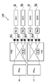
- FIG. 1 shows a configuration diagram of an optical receiver 100 for digital coherent optical communication.
- the optical receiver 100 includes a polarization separator (PBSRX, PBSLO), a 90-degree optical hybrid (HYBX, HYBY), and a balanced photodiode (PD1 to PD1) from the input side of the left received light (RX) and local emission (LO). 4), a transimpedance amplifier (TIA1 to 4), and an A / D converter (ADC1 to 4).
- PBSRX, PBSLO polarization separator
- HYBX, HYBY 90-degree optical hybrid
- PD1 to PD1 balanced photodiode
- RX left received light
- LO local emission
- TIA1 to 4 transimpedance amplifier
- ADC1 to 4 ADC1 to 4
- the polarization separators PBSRX and PBSLO branch the received light (RX) and local emission (LO) to different output ports according to their polarization state.
- the 90-degree optical hybrid (HYBX, HYBY) branches the received light of each polarized wave and the local emission, and causes them to interfere with each other. At that time, one of the branched station emissions is interfered with the received light by giving a phase difference of 90 degrees to the other station emission. Interference light of each polarization is converted into an electric signal by a photodiode (PD1 to 4) and a transimpedance amplifier (TIA1 to 4), and converted from an analog electric signal to a digital signal by an A / D converter (ADC1 to 4). Will be done.
- PD1 to 4 photodiode
- TIA1 to 4 transimpedance amplifier
- ADC1 to 4 ADC1 to 4
- the optical 90 degree hybrid is used by using DSP (Digital signal processing).
- DSP Digital signal processing
- a method of compensating for the phase error has been proposed.
- Patent Document 1 a known signal can be used to compensate for the transfer function of an optical receiver (including the phase error of an optical 90 degree hybrid).
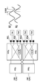
- phase error of the conventional 90-degree optical hybrid shown in FIG. 2 there is a method for evaluating the phase error of the 90-degree optical hybrid using a beat frequency as described in Non-Patent Document 1.
- two CW (Continious Waveform: continuous wave) optical CW1 (frequency f1) and CW2 (frequency f2) with different oscillation frequencies are input to the optical receiver, and A / D conversion output from the transimpedance amplifier.
- the phase error of the 90 degree hybrid can be evaluated from the phase difference of the previous beat electric signal (the frequency of the beat electric signal corresponds to the difference between the oscillation frequencies of the two light sources).
- the four output channels of the transimpedance amplifier are the in-phase component of X-polarized light (XI), the orthogonal component of X-polarized light (XQ), the in-phase component of Y-polarized light (YI), and the orthogonal component of Y-polarized light.
- XI X-polarized light
- XQ orthogonal component of X-polarized light
- YI Y-polarized light
- YQ the phase difference of the beat electric signal output from the XI channel and the XQ channel is also 90 degrees. ..
- phase difference of the 90-degree hybrid of X polarization deviates from 90 degrees
- the phase difference of the beat electric signal output from the XI channel and the XQ channel also corresponds to the phase difference with respect to 90 degrees.
- the phase error of the 90-degree hybrid of X polarization can be evaluated from the phase difference of the beat electric signals output from the XI channel and the XQ channel. The same applies to the method for evaluating the phase error of the 90-degree hybrid of Y polarization.
- the phase difference of the 90-degree optical hybrid is accurate.
- the phase difference according to the skew is added to the phase difference of the beat electric signal output from the XI channel and the XQ channel of the transimpedance amplifier. .. Therefore, in the conventional evaluation method using the beat frequency, the phase difference of the optical 90-degree hybrid and the phase difference due to the inter-channel skew cannot be evaluated separately. Therefore, when the optical receiver has the inter-channel skew, There is a problem that the phase error of the 90-degree optical hybrid cannot be evaluated with high accuracy.
- the present invention has been made in view of the above problems, and even when the optical receiver has an inter-channel skew, it is possible to evaluate only the phase error of the optical 90-degree hybrid with high accuracy. It is an object of the present invention to provide an evaluation method and an evaluation device for an optical receiver.
- An example of an embodiment of the present invention is characterized by having the following configurations in order to achieve such an object.
- the arithmetic step of decomposing into the product of the matrix is an arithmetic step of decomposing the matrix representing the transfer function of the optical receiver into the product of the shear matrix, the scaling matrix, and the rotation matrix.
- the shear matrix is obtained by decomposing the matrix representing the transfer function of the optical receiver into the product of the rotation matrix and the upper triangular matrix by QR decomposition, and decomposing the upper triangular matrix into the product of the shear matrix and the scaling matrix.
- the method for evaluating an optical receiver according to the second configuration is obtained by decomposing the matrix representing the transfer function of the optical receiver into the product of the rotation matrix and the upper triangular matrix by QR decomposition, and decomposing the upper triangular matrix into the product of the shear matrix and the scaling matrix.
- (Structure 4) It is an evaluation device for an optical receiver having a 90-degree optical hybrid. Equipped with a transmitter and receiver connected by a transmission line, The transmitter acquires a known signal generator that generates a sequence of known signals and an estimation result of the transfer function of the optical transmitter from the transmitter transfer function estimation unit of the receiver to compensate the transfer function of the optical transmitter. Equipped with a transmitter compensator and an optical transmitter The receiver includes an optical receiver, a receiver compensation unit, first and second receiver transfer function estimation units, and the transmitter transfer function estimation unit. An evaluation device for an optical receiver, which evaluates the optical receiver by decomposing the estimated transfer function of the optical receiver into terms of 90-degree hybrid phase error, interchannel gain imbalance, and residual rotation. ..
- the transmitter transfer function estimation unit includes the first digital data acquired by the receiver when the first known signal is transmitted from the transmitter to the receiver, and a temporary transfer function of the optical receiver. From, the transfer function of the optical transmitter is estimated, The first receiver transfer function estimation unit estimates a temporary transfer function of the optical receiver from the digital data acquired by the receiver when the ASE signal is input to the input terminal of the optical receiver. The second receiver transfer function estimation unit includes the second digital data acquired by the receiver when the second known signal is transmitted from the transmitter to the receiver, and the estimated optical transmitter. The transfer function of the optical receiver is estimated from the transfer function of The evaluation device for an optical receiver according to the configuration 4, characterized in that.
- an evaluation method for an optical receiver and an evaluation device for an optical receiver that enable highly accurate evaluation of only the phase error of an optical 90-degree hybrid even when the optical receiver has an interchannel skew. Can be provided.
- FIG. 3 is a diagram showing an evaluation device 300 for an optical receiver according to an embodiment of the present invention.
- the transmission unit 400 of the evaluation device 300 transmits an optical signal to the reception unit 500 via an optical fiber or the like.
- the transmitter 400 includes a known signal generation unit 401, a transmitter compensation unit 402, and an optical transmitter 403.
- the known signal generation unit 401 generates a sequence of known signals for each of the XI channel, the XQ channel, the YI channel, and the YQ channel, and transmits the sequence to the transmitter compensation unit 402.
- the sequence of known signals is shared between the transmitting unit 400 and the receiving unit 500.
- the transmitter compensation unit 402 acquires the estimation result of the transfer function of the optical transmitter 403 from the transmitter transfer function estimation unit 504 of the receiver unit 500.
- the transmitter compensation unit 402 compensates the transfer function of the optical transmitter 403 based on the estimation result.
- the optical transmitter 403 generates an optical signal by modulating orthogonal linearly polarized light in a series of known signals output from the transmitter compensation unit 402.
- the generated optical signal is supplied to the receiving unit 500 via the optical transmission line.
- the receiver 500 includes an optical receiver 600, a receiver compensation unit 502, first and second receiver transfer function estimation units 503-1 and 2, and a local oscillator LD (Laser Diode) 501.
- LD Laser Diode
- the optical receiver 600 to be evaluated includes a polarization separator (PBS1, 2), an optical 90-degree hybrid (HYB1, 2), a photodiode (PD1 to 4), and a transimpedance amplifier (TIA1 to 4). , And an A / D converter (ADC).
- PBS1, 2 polarization separator
- HYB1, 2 optical 90-degree hybrid
- PD1 to 4 photodiode
- TIA1 to 4 transimpedance amplifier
- ADC A / D converter
- the polarization separators branch the received light and the local emission output from the local oscillator LD to different output ports according to their polarization states.
- the 90-degree optical hybrid branches the received light of each polarized wave and the local emission, respectively, and causes them to interfere with each other. At that time, one of the branched station emissions is interfered with the received light by giving a phase difference of 90 degrees to the other station emission. Interference light of each polarization is converted into an electric signal by a photodiode (PD1 to 4) and a transimpedance amplifier (TIA1 to 4), and is converted from an analog electric signal to a digital signal by an A / D converter (ADC). ..
- the receiver compensation unit 502 acquires the digital output of the optical receiver 600 from the optical receiver 600, and acquires the estimation result of the transfer function of the optical receiver 600 from the second receiver transfer function estimation unit 503-2. , The transfer function of the optical receiver 600 is compensated based on the estimation result.
- the first receiver transfer function estimation unit 503-1 receives light from digital data acquired by the receiver 500 when an ASE (Amplified Spontaneous Emission) signal corresponding to white noise is input to the input end of the optical receiver 600. Estimate the tentative transfer function of the receiver 600.
- the ASE signal can be generated from an optical amplifier.
- An optical amplifier may be included in the transmission line (optical fiber), or an optical amplifier may be prepared separately.
- the transmitter transfer function estimation unit 504 includes the first digital data acquired by the receiver when the first known signal is transmitted from the transmitter 400 to the receiver 500, and a temporary transfer function of the optical receiver 600. From, the transfer function of the optical transmitter 403 is estimated.
- the second receiver transfer function estimation unit 503-2 transmits the second digital data acquired by the receiver 500 when the second known signal is transmitted from the transmitter 400 to the receiver 500, and the estimated optical transmission.
- the transfer function of the optical receiver 600 is estimated from the transfer function of the machine 403.
- FIG. 4 is a flowchart showing an evaluation method of an optical receiver according to an embodiment of the present invention.
- Step S1 the first receiver transfer function estimation unit 503-1 estimates a temporary transfer function of the optical receiver 600.
- Step S2 the transmitter transfer function estimation unit 504 estimates the transfer function of the optical transmitter 403.
- Step S3 the second receiver transfer function estimation unit 503-2 estimates the transfer function of the optical receiver 600.
- the transfer function of the receiver estimated in step S3 is decomposed into the terms of 90-degree hybrid phase error, interchannel gain imbalance, and residual rotation for optical reception.
- step S4 for evaluating the machine is different from the flowchart described in Patent Document 1. Since the detailed operations from step S1 to step S3 are the same as those in Patent Document 1, detailed description thereof will be omitted.
- Step S4 The detailed contents of step S4 will be described.
- the transfer function is represented by the 2x2 matrix shown in Equations 1 and 2.
- the 2x2 matrix in Equation 1 represents the transfer function on the X-polarized side of the optical receiver 600
- the 2x2 table in Equation 2 represents the transfer function on the Y-polarized side of the optical receiver 600.
- the 2x2 matrix representing the transfer function on the X-polarized side of the optical receiver 600 is the phase error of the 90-degree hybrid on the X-polarized side, the gain error of the XI channel and the XQ channel, and the various transmission characteristic compensation errors generated in step S3. Is the product of. The same applies to the 2x2 matrix representing the transfer function on the Y polarization side of the optical receiver 600.
- step S4 is to obtain a matrix representing the phase error of the optical 90 degree hybrid from these 2x2 matrices.
- a method of obtaining the phase error of the 90-degree optical hybrid on the X-polarized side from the 2x2 matrix representing the transfer function on the X-polarized side of the optical receiver 600 will be described.
- the matrix representing the phase error of the 90-degree optical hybrid on the X polarization side is represented by the shear matrix of Equation 3.
- ⁇ X / 2 is the phase error of the optical 90 degree hybrid.
- the matrix representing the gain error of the XI channel and the XQ channel is represented by the scaling matrix of Equation 4.
- g XI is the gain of the XI channel
- g XQ is the gain of the XQ channel
- their ratio represents the gain error between the channels.
- ⁇ X is the rotation angle
- Equation 1 is expressed as the product of Equations 3, 4, and 5, and the matrix representing the phase error of the 90-degree optical hybrid on the X-polarized side is obtained to obtain the 90-degree optical hybrid on the X-polarized side.
- the phase error of can be calculated.
- the 2x2 matrix of Equation 1 is decomposed into the product of the rotation matrix and the upper triangular matrix by QR decomposition. Then, the 2x2 matrix of Equation 1 is expressed as the equation of Equation 6.
- phase error of the 90-degree optical hybrid on the X polarization side can be calculated by obtaining the inverse tangent of b / a obtained in Equation 7, and the evaluation of the optical receiver is evaluated based on this phase error. It can be carried out.
- an evaluation method for an optical receiver and an optical receiver that enable highly accurate evaluation of only the phase error of an optical 90-degree hybrid even when the optical receiver has an inter-channel skew.
- a receiver evaluation device can be provided.
- Optical receiver 100 Optical receiver 300 Evaluation device 400 Transmitter 401 Known signal generator 402 Transmitter compensation 403 Optical transmitter 500 Receiver 501 Local oscillator LD 502 Receiver compensation unit 503-1, 2 First and second receiver transfer function estimation unit 504 Transmitter transfer function estimation unit 600 Optical receiver
Landscapes
- Physics & Mathematics (AREA)
- Electromagnetism (AREA)
- Engineering & Computer Science (AREA)
- Computer Networks & Wireless Communication (AREA)
- Signal Processing (AREA)
- Optical Communication System (AREA)
Abstract
光受信機にチャネル間スキューがある場合においても、光90度ハイブリッドの位相誤差のみを精度高く評価することを可能とする光受信機の評価方法及び評価装置を提供する。光受信機の伝達関数を行列の積に分解する演算により、前記光90度ハイブリッドの位相誤差を算出して光受信機を評価することを特徴とする光90度ハイブリッドを有する光受信機の評価方法及び評価装置とした。
Description
本発明は、コヒーレント光通信用の光受信機の評価方法及び光受信機の評価装置に関する。
従来より、デジタル信号処理とコヒーレント検波を組み合わせたデジタルコヒーレント技術に基づいた光送受信機の開発が進んでいる。
1波長あたり100Gb/sの光送受信機では、ボーレート(Baud rate)と変調方式は例えば32Gbaud PDM-QPSK(偏波多重-4位相偏移変調)である。光送信機は直交した直線偏光(X偏波とY偏波)を、それぞれQPSKのベースバンド信号で変調することでPDM-QPSK光信号を生成する。光受信機は受信光と局発光をコヒーレント検波することで光信号をベースバンド信号に変換し、デジタル信号処理(DSP)によってQPSKを復調し送信データを再生する。
1波長あたりの伝送容量を増やすために、400Gb/sの光送受信機では、ボーレートと変調方式は例えば64Gbaud PDM-16QAM(偏波多重-16直交振幅位相変調)、又は43Gbaud PDM-64QAMである。このように、今後の光送受信機では、1波長あたりの伝送容量を拡大させるためにボーレートの上昇と変調方式の多値化が進む。
図1にデジタルコヒーレント光通信用の光受信機100の構成図を示す。光受信機100は、左の受信光(RX)、局発光(LO)の入力側から偏波分離器(PBSRX、PBSLO)、光90度ハイブリッド(HYBX、HYBY)、バランス型フォトダイオード(PD1~4)、トランスインピーダンスアンプ(TIA1~4)、及びA/D変換器(ADC1~4)とで構成される。
偏波分離器PBSRX、PBSLO)は、受信光(RX)、及び局発光(LO)をそれらの偏波状態に応じて異なる出力ポートに分岐する。光90度ハイブリッド(HYBX、HYBY)は、各偏波の受信光と局発光をそれぞれ分岐し、それらを干渉させる。その際、分岐された局発光のうち一方の局発光は他方の局発光に対して90度の位相差を与えて受信光と干渉される。各偏波の干渉光はフォトダイオード(PD1~4)とトランスインピーダンスアンプ(TIA1~4)とにより電気信号に変換され、A/D変換器(ADC1~4)によりアナログ電気信号からデジタル信号へ変換される。
変調方式の多値化が進むにつれ、光90度ハイブリッドの位相誤差(90度からのずれ)が伝送特性に与える影響は顕著となるため、DSP(Digital signal processing)を用いて光90度ハイブリッドの位相誤差を補償する方法が提案されている。例えば、特許文献1が示すように、既知信号を用いて光受信機の伝達関数(光90度ハイブリッドの位相誤差を含む)を補償することできる。
一方で、図2に示す従来の光90度ハイブリッドの位相誤差の評価方法として、非特許文献1に記載されているようなビート周波数を用いた光90度ハイブリッドの位相誤差の評価方法がある。この評価方法では、発振周波数の異なる2つのCW(Continious Waveform:連続波)光CW1(周波数f1)、CW2(周波数f2)を光受信機に入力し、トランスインピーダンスアンプから出力されるA/D変換前のビート電気信号(ビート電気信号の周波数は二つの光源の発振周波数の差に相当する)の位相差から90度ハイブリッドの位相誤差を評価することができる。
具体的には、トランスインピーダンスアンプの4つの出力チャネルをX偏波の同相成分(XI)、X偏波の直交成分(XQ)、Y偏波の同相成分(YI)、Y偏波の直交成分(YQ)とすると、X偏波の90度ハイブリッドの位相差が90度の場合(理想的な場合)には、XIチャネルとXQチャネルから出力されるビート電気信号の位相差も90度となる。
一方、X偏波の90度ハイブリッドの位相差が90度からずれている場合には、XIチャネルとXQチャネルから出力されるビート電気信号の位相差も90度に対してそのずれに相当した位相ずれが発生する。よって、XIチャネルとXQチャネルから出力されるビート電気信号の位相差から、X偏波の90度ハイブリッドの位相誤差を評価することができる。Y偏波の90度ハイブリッドの位相誤差の評価方法についても同様である。
Implementation Agreement for CFP2-Analog Coherent Optics Module IA# OIF-CFP2-ACO-01.0
従来、既知信号を用いて光受信機の伝達関数を補償する場合には、光受信機で発生するその他の不完全性(例えば、チャネル間の利得バラつき)を含む伝達関数を推定及び補償していた。したがって、光90度ハイブリッドの位相誤差のみを推定することはできないという問題があった。
また、従来のビート周波数を用いた光90度ハイブリッドの位相誤差の評価方法では、光受信機のチャネル間にスキュー(遅延時間の差)がある場合には、光90度ハイブリッドの位相差を精度高く評価できないという課題があった。例えば、XIチャネルとXQチャネルとの間にスキューがある場合には、トランスインピーダンスアンプのXIチャネルとXQチャネルから出力されるビート電気信号の位相差にスキューに応じた位相差が加わってしまっていた。したがって、従来のビート周波数を用いた評価方法では、光90度ハイブリッドの位相差とチャネル間スキューに起因する位相差を分けて評価することができないため、光受信機にチャネル間スキューがある場合、光90度ハイブリッドの位相誤差を精度高く評価することができないという課題があった。
本発明は上記の課題を鑑みてなされたものであり、光受信機にチャネル間スキューがある場合においても、光90度ハイブリッドの位相誤差のみを精度高く評価することを可能とする光受信機の評価方法及び光受信機の評価装置を提供することを目的としている。
本発明の実施形態の一例は、このような目的を達成するために、以下のような構成を備えることを特徴とする。
(構成1)
光90度ハイブリッドを有する光受信機の評価方法において、前記光受信機の伝達関数を行列の積に分解する演算ステップと、
前記演算ステップにより分解された行列の積により前記光90度ハイブリッドの位相誤差を算出して光受信機を評価するステップを備える
ことを特徴とする光受信機の評価方法。
光90度ハイブリッドを有する光受信機の評価方法において、前記光受信機の伝達関数を行列の積に分解する演算ステップと、
前記演算ステップにより分解された行列の積により前記光90度ハイブリッドの位相誤差を算出して光受信機を評価するステップを備える
ことを特徴とする光受信機の評価方法。
(構成2)
前記行列の積に分解する演算ステップは、前記光受信機の伝達関数を表す行列を剪断行列、拡大縮小行列、および回転行列の積に分解する演算ステップであり、
前記評価するステップは、前記剪断行列の係数から前記光受信機の光90度ハイブリッドの位相誤差を得るステップである
ことを特徴とする構成1に記載の光受信機の評価方法。
前記行列の積に分解する演算ステップは、前記光受信機の伝達関数を表す行列を剪断行列、拡大縮小行列、および回転行列の積に分解する演算ステップであり、
前記評価するステップは、前記剪断行列の係数から前記光受信機の光90度ハイブリッドの位相誤差を得るステップである
ことを特徴とする構成1に記載の光受信機の評価方法。
(構成3)
前記剪断行列は、前記光受信機の伝達関数を表す行列をQR分解によって回転行列と上三角行列の積に分解し、前記上三角行列を剪断行列と拡大縮小行列の積に分解して得る
ことを特徴とする構成2に記載の光受信機の評価方法。
前記剪断行列は、前記光受信機の伝達関数を表す行列をQR分解によって回転行列と上三角行列の積に分解し、前記上三角行列を剪断行列と拡大縮小行列の積に分解して得る
ことを特徴とする構成2に記載の光受信機の評価方法。
(構成4)
光90度ハイブリッドを有する光受信機の評価装置であって、
伝送路で接続された送信部と受信部を備え、
前記送信部は、既知信号の系列を生成する既知信号生成部と、光送信機の伝達関数の推定結果を前記受信部の送信機伝達関数推定部から取得して光送信機の伝達関数を補償する送信機補償部、および光送信機を備え、
前記受信部は、光受信機と、受信器補償部、第1及び第2の受信器伝達関数推定部、および前記送信機伝達関数推定部を備え、
推定した前記光受信機の伝達関数を、90度ハイブリッドの位相誤差、チャネル間利得インバランス、残留回転の項に分解して前記光受信機を評価する
ことを特徴とする光受信機の評価装置。
光90度ハイブリッドを有する光受信機の評価装置であって、
伝送路で接続された送信部と受信部を備え、
前記送信部は、既知信号の系列を生成する既知信号生成部と、光送信機の伝達関数の推定結果を前記受信部の送信機伝達関数推定部から取得して光送信機の伝達関数を補償する送信機補償部、および光送信機を備え、
前記受信部は、光受信機と、受信器補償部、第1及び第2の受信器伝達関数推定部、および前記送信機伝達関数推定部を備え、
推定した前記光受信機の伝達関数を、90度ハイブリッドの位相誤差、チャネル間利得インバランス、残留回転の項に分解して前記光受信機を評価する
ことを特徴とする光受信機の評価装置。
(構成5)
前記送信機伝達関数推定部は、前記送信部から前記受信部に第1の既知信号を伝送させたときに前記受信部が取得した第1のデジタルデータと、前記光受信機の仮の伝達関数とから、前記光送信機の伝達関数を推定し、
前記第1の受信器伝達関数推定部は、前記光受信機の入力端にASE信号を入力された時に前記受信部が取得したデジタルデータから、前記光受信機の仮の伝達関数を推定し、
前記第2の受信器伝達関数推定部は、前記送信部から前記受信部に第2の既知信号を伝送させたときに前記受信部が取得した第2のデジタルデータと、推定した前記光送信機の伝達関数とから、前記光受信機の伝達関数を推定する、
ことを特徴とする構成4に記載の光受信機の評価装置。
前記送信機伝達関数推定部は、前記送信部から前記受信部に第1の既知信号を伝送させたときに前記受信部が取得した第1のデジタルデータと、前記光受信機の仮の伝達関数とから、前記光送信機の伝達関数を推定し、
前記第1の受信器伝達関数推定部は、前記光受信機の入力端にASE信号を入力された時に前記受信部が取得したデジタルデータから、前記光受信機の仮の伝達関数を推定し、
前記第2の受信器伝達関数推定部は、前記送信部から前記受信部に第2の既知信号を伝送させたときに前記受信部が取得した第2のデジタルデータと、推定した前記光送信機の伝達関数とから、前記光受信機の伝達関数を推定する、
ことを特徴とする構成4に記載の光受信機の評価装置。
本発明によれば、光受信機にチャネル間スキューがある場合においても光90度ハイブリッドの位相誤差のみを精度高く評価することを可能とする光受信機の評価方法及び光受信機の評価装置を提供することができる。
以下、図面を参照しながら本発明の実施形態について詳細に説明する。
(実施形態)
図3は、本発明の実施形態に係る光受信機の評価装置300を示す図である。評価装置300の送信部400は、光ファイバ等を介して光信号を受信部500に送信する。
図3は、本発明の実施形態に係る光受信機の評価装置300を示す図である。評価装置300の送信部400は、光ファイバ等を介して光信号を受信部500に送信する。
送信部400は、既知信号生成部401、送信機補償部402、及び光送信機403を備える。既知信号生成部401は、XIチャネル、XQチャネル、YIチャネル、YQチャネルに対して、それぞれ既知信号の系列を生成し、送信機補償部402に送信する。既知信号の系列は、送信部400と受信部500の間で共有されている。
送信機補償部402は、光送信機403の伝達関数の推定結果を、受信部500の送信機伝達関数推定部504から取得する。送信機補償部402は、その推定結果に基づいて光送信機403の伝達関数を補償する。
光送信機403は、送信機補償部402から出力された既知信号の系列で直交した直線偏光を変調することで、光信号を生成する。生成された光信号は、光伝送路を介して受信部500に供給される。
受信部500は光受信機600、受信器補償部502、第1及び第2の受信器伝達関数推定部503-1、2、及び局発LD(Laser Diode)501を備える。
評価対象となる光受信機600は図1と同様、偏波分離器(PBS1,2)、光90度ハイブリッド(HYB1,2)、フォトダイオード(PD1~4)、トランスインピーダンスアンプ(TIA1~4)、及びA/D変換器(ADC)とで構成される。
偏波分離器(PBS1,2)は、受信光及び局発LDから出力される局発光を、それらの偏波状態に応じて異なる出力ポートに分岐する。光90度ハイブリッド(HYB1,2)は、各偏波の受信光と局発光をそれぞれ分岐し、それらを干渉させる。その際、分岐された局発光のうち一方の局発光は他方の局発光に対して90度の位相差を与えて受信光と干渉される。各偏波の干渉光はフォトダイオード(PD1~4)とトランスインピーダンスアンプ(TIA1~4)とにより電気信号に変換され、A/D変換器(ADC)によりアナログ電気信号からデジタル信号へ変換される。
受信機補償部502は、光受信機600のデジタル出力を光受信機600から取得し、および光受信機600の伝達関数の推定結果を第2の受信機伝達関数推定部503-2から取得し、その推定結果に基づいて光受信機600の伝達関数を補償する。
第1の受信機伝達関数推定部503-1は、光受信機600の入力端に白色雑音に相当するASE(Amplified Spontaneous Emission)信号を入力された時に受信部500が取得したデジタルデータから、光受信機600の仮の伝達関数を推定する。ASE信号は光アンプから発生させることができる。伝送路(光ファイバ)に光アンプを含んでもよいし、別途光アンプを用意してもよい。
送信機伝達関数推定部504は、送信部400から受信部500に第1の既知信号を伝送させたときに受信部が取得した第1のデジタルデータと、光受信機600の仮の伝達関数とから、光送信機403の伝達関数を推定する。
第2の受信機伝達関数推定部503-2は、送信部400から受信部500に第2の既知信号を伝送させたときに受信部500が取得した第2のデジタルデータと、推定した光送信機403の伝達関数とから、光受信機600の伝達関数を推定する。
図4は、本発明の実施形態に係る光受信機の評価方法を示すフローチャートである。
(ステップS1) まず、第1の受信機伝達関数推定部503-1にて、光受信機600の仮の伝達関数を推定する。
(ステップS2) 次に、送信機伝達関数推定部504にて、光送信機403の伝達関数を推定する。
(ステップS3) 次に、第2の受信機伝達関数推定部503-2にて、光受信機600の伝達関数を推定する。ここまでは従来技術と同様であるが、本願発明では、ステップS3で推定した受信機の伝達関数を、90度ハイブリッドの位相誤差、チャネル間利得インバランス、残留回転の項に分解して光受信機を評価するステップS4を有することが、特許文献1記載のフローチャートと異なる。ステップS1からステップS3までの詳細動作は特許文献1と同様のため詳細な説明は省略する。
(ステップS4) ステップS4の詳細な内容について説明する。ステップS3により光受信機の伝達関数を推定した結果、その伝達関数は式1と式2に示す2x2行列で表現される。


式1の2x2行列は光受信機600のX偏波側の伝達関数を表し、式2の2x2表列は光受信機600のY偏波側の伝達関数を表す。光受信機600のX偏波側の伝達関数を表す2x2行列はX偏波側の90度ハイブリッドの位相誤差、XIチャネルとXQチャネルの利得誤差、及びステップS3で発生する種々の伝送特性補償誤差の積である。光受信機600のY偏波側の伝達関数を表す2x2行列も同様である。
ステップS4の目的は、これらの2x2行列から光90度ハイブリッドの位相誤差を表す行列を求めることである。以下,光受信機600のX偏波側の伝達関数を表す2x2行列から、X偏波側の光90度ハイブリッドの位相誤差を求める方法について説明する。
X偏波側の光90度ハイブリッドの位相誤差を表す行列は、式3の剪断行列で表される。

ここでδX/2は、光90度ハイブリッドの位相誤差である。
また、XIチャネルとXQチャネルの利得誤差を表す行列は、式4の拡大縮小行列で表される。

ここでgXIはXIチャネルの利得、gXQはXQチャネルの利得であり、それらの比がチャネル間の利得誤差を表す。
また、ステップS3で発生する種々の伝送特性補償誤差は、式5の回転行列で表現される。

ここで、θXは回転角である。
したがって、式1の行列を式3、式4、式5の積として表現し、X偏波側の光90度ハイブリッドの位相誤差を表す行列を求めることで、X偏波側の光90度ハイブリッドの位相誤差を算出することができる。
そのために、まず、式1の2x2行列をQR分解により、回転行列と上三角行列の積に分解する。すると式1の2x2行列は式6の式のように表される。

次に、式6の上三角行列を、式7の式のように分解することで、2x2行列を式3、式4、式5の積に分解することができる。

したがって、式7で得られたb/aの逆正接を求めることで、X偏波側の光90度ハイブリッドの位相誤差を算出することができ、この位相誤差に基づいて光受信機の評価を行うことができる。
以上説明したように、本発明によれば、光受信機にチャネル間スキューがある場合においても光90度ハイブリッドの位相誤差のみを精度高く評価することを可能とする光受信機の評価方法及び光受信機の評価装置を提供することができる。
100 光受信機
300 評価装置
400 送信部
401 既知信号生成部
402 送信機補償部
403 光送信機
500 受信部
501 局発LD
502 受信器補償部
503-1、2 第1、第2の受信器伝達関数推定部
504 送信機伝達関数推定部
600 光受信機
300 評価装置
400 送信部
401 既知信号生成部
402 送信機補償部
403 光送信機
500 受信部
501 局発LD
502 受信器補償部
503-1、2 第1、第2の受信器伝達関数推定部
504 送信機伝達関数推定部
600 光受信機
Claims (5)
- 光90度ハイブリッドを有する光受信機の評価方法において、前記光受信機の伝達関数を行列の積に分解する演算ステップと、
前記演算ステップにより分解された行列の積により前記光90度ハイブリッドの位相誤差を算出して光受信機を評価するステップを備える
ことを特徴とする光受信機の評価方法。 - 前記行列の積に分解する演算ステップは、前記光受信機の伝達関数を表す行列を剪断行列、拡大縮小行列、および回転行列の積に分解する演算ステップであり、
前記評価するステップは、前記剪断行列の係数から前記光受信機の光90度ハイブリッドの位相誤差を得るステップである
ことを特徴とする請求項1に記載の光受信機の評価方法。 - 前記剪断行列は、前記光受信機の伝達関数を表す行列をQR分解によって回転行列と上三角行列の積に分解し、前記上三角行列を剪断行列と拡大縮小行列の積に分解して得る
ことを特徴とする請求項2に記載の光受信機の評価方法。 - 光90度ハイブリッドを有する光受信機の評価装置であって、
伝送路で接続された送信部と受信部を備え、
前記送信部は、既知信号の系列を生成する既知信号生成部と、光送信機の伝達関数の推定結果を前記受信部の送信機伝達関数推定部から取得して光送信機の伝達関数を補償する送信機補償部、および光送信機を備え、
前記受信部は、光受信機と、受信器補償部、第1及び第2の受信器伝達関数推定部、および前記送信機伝達関数推定部を備え、
推定した前記光受信機の伝達関数を、90度ハイブリッドの位相誤差、チャネル間利得インバランス、残留回転の項に分解して前記光受信機を評価する
ことを特徴とする光受信機の評価装置。 - 前記送信機伝達関数推定部は、前記送信部から前記受信部に第1の既知信号を伝送させたときに前記受信部が取得した第1のデジタルデータと、前記光受信機の仮の伝達関数とから、前記光送信機の伝達関数を推定し、
前記第1の受信器伝達関数推定部は、前記光受信機の入力端にASE信号を入力された時に前記受信部が取得したデジタルデータから、前記光受信機の仮の伝達関数を推定し、
前記第2の受信器伝達関数推定部は、前記送信部から前記受信部に第2の既知信号を伝送させたときに前記受信部が取得した第2のデジタルデータと、推定した前記光送信機の伝達関数とから、前記光受信機の伝達関数を推定する、
ことを特徴とする請求項4に記載の光受信機の評価装置。
Priority Applications (1)
| Application Number | Priority Date | Filing Date | Title |
|---|---|---|---|
| US17/432,736 US11736202B2 (en) | 2019-03-11 | 2020-03-06 | Optical receiver evaluation method and optical receiver evaluation apparatus |
Applications Claiming Priority (2)
| Application Number | Priority Date | Filing Date | Title |
|---|---|---|---|
| JP2019-043740 | 2019-03-11 | ||
| JP2019043740A JP7235963B2 (ja) | 2019-03-11 | 2019-03-11 | 光受信機の評価方法及び光受信機の評価装置 |
Publications (1)
| Publication Number | Publication Date |
|---|---|
| WO2020184445A1 true WO2020184445A1 (ja) | 2020-09-17 |
Family
ID=72426263
Family Applications (1)
| Application Number | Title | Priority Date | Filing Date |
|---|---|---|---|
| PCT/JP2020/009741 Ceased WO2020184445A1 (ja) | 2019-03-11 | 2020-03-06 | 光受信機の評価方法及び光受信機の評価装置 |
Country Status (3)
| Country | Link |
|---|---|
| US (1) | US11736202B2 (ja) |
| JP (1) | JP7235963B2 (ja) |
| WO (1) | WO2020184445A1 (ja) |
Families Citing this family (3)
| Publication number | Priority date | Publication date | Assignee | Title |
|---|---|---|---|---|
| CN111705163A (zh) | 2020-05-28 | 2020-09-25 | 中山大学达安基因股份有限公司 | 基于热对流pcr的新型冠状病毒快速检测试剂盒 |
| CN114915349A (zh) * | 2021-02-09 | 2022-08-16 | 中兴通讯股份有限公司 | 相干检测方法、装置及光传输系统 |
| WO2024004091A1 (ja) * | 2022-06-29 | 2024-01-04 | 日本電信電話株式会社 | 光受信機及び信号処理方法 |
Citations (3)
| Publication number | Priority date | Publication date | Assignee | Title |
|---|---|---|---|---|
| JPS6319487B2 (ja) * | 1978-05-08 | 1988-04-22 | Ici Plc | |
| US20140341564A1 (en) * | 2013-05-16 | 2014-11-20 | Exfo Inc. | Method and system for common-mode-rejection-ratio (cmrr) characterization of an integrated coherent receiver |
| JP2015109576A (ja) * | 2013-12-05 | 2015-06-11 | 株式会社日立製作所 | 光受信器および光信号受信方法 |
Family Cites Families (6)
| Publication number | Priority date | Publication date | Assignee | Title |
|---|---|---|---|---|
| US6515276B2 (en) * | 2001-03-17 | 2003-02-04 | Agilent Technologies, Inc. | Heterodyne optical spectrum analyzer with provisions for intensity noise subtraction |
| US8023833B2 (en) * | 2007-03-22 | 2011-09-20 | Opnext Subsystems, Inc. | Optical receivers with controllable transfer function bandwidth and gain imbalance |
| JP5650806B2 (ja) * | 2012-06-06 | 2015-01-07 | ゼットティーイー(ユーエスエー)インコーポレーテッド | 光通信システムにおける予等化およびポスト等化の方法および装置 |
| US9729244B2 (en) * | 2014-10-20 | 2017-08-08 | Adva Optical Networking Se | Apparatus and method for monitoring signal quality of a modulated optical signal |
| CN107113258B (zh) * | 2014-11-13 | 2020-10-09 | 瑞典爱立信有限公司 | 相干光学接收器中光学通信信号的数字信号处理 |
| JP6319487B1 (ja) | 2017-03-14 | 2018-05-09 | Nttエレクトロニクス株式会社 | 光伝送特性推定方法、光伝送特性補償方法、光伝送特性推定システム及び光伝送特性補償システム |
-
2019
- 2019-03-11 JP JP2019043740A patent/JP7235963B2/ja active Active
-
2020
- 2020-03-06 US US17/432,736 patent/US11736202B2/en active Active
- 2020-03-06 WO PCT/JP2020/009741 patent/WO2020184445A1/ja not_active Ceased
Patent Citations (3)
| Publication number | Priority date | Publication date | Assignee | Title |
|---|---|---|---|---|
| JPS6319487B2 (ja) * | 1978-05-08 | 1988-04-22 | Ici Plc | |
| US20140341564A1 (en) * | 2013-05-16 | 2014-11-20 | Exfo Inc. | Method and system for common-mode-rejection-ratio (cmrr) characterization of an integrated coherent receiver |
| JP2015109576A (ja) * | 2013-12-05 | 2015-06-11 | 株式会社日立製作所 | 光受信器および光信号受信方法 |
Non-Patent Citations (2)
| Title |
|---|
| "Implementation Agreement for a CFP2 Analogue Coherent Optics Module IA OIF-CFP2-ACO-01.0", OIF. OPTICAL INTERNETWORKING FORUM, IA OIF-CFP2-ACO-01.0, 22 January 2016 (2016-01-22), pages 1 - 92, XP055738617 * |
| PAINCHAUD Y. ET AL.: "Performance of balanced detection in a coherent receiver", OPTICS EXPRESS, vol. 17, no. 5, 2 March 2009 (2009-03-02), pages 3659 - 3672, XP055738619, DOI: 10.1364/OE.17.003659 * |
Also Published As
| Publication number | Publication date |
|---|---|
| JP7235963B2 (ja) | 2023-03-09 |
| US11736202B2 (en) | 2023-08-22 |
| US20220140913A1 (en) | 2022-05-05 |
| JP2020150302A (ja) | 2020-09-17 |
Similar Documents
| Publication | Publication Date | Title |
|---|---|---|
| US8406638B2 (en) | Coherent light receiving system | |
| US8953953B2 (en) | Coherent optical receiver, apparatus and method for detecting inter-channel skew in coherent optical receiver | |
| US8331805B2 (en) | Digital coherent optical receiver | |
| US8761600B2 (en) | In-band supervisory data modulation | |
| US9954615B2 (en) | Optical up/down conversion-type optical phase conjugate pair signal transmission/reception circuit | |
| US6917031B1 (en) | Method for quadrature phase angle correction in a coherent receiver of a dual-polarization optical transport system | |
| EP2946493B1 (en) | Optical polarization demultiplexing for a coherent-detection scheme | |
| EP2214332B1 (en) | Optical communication system and optical receiver | |
| JP5601205B2 (ja) | 光受信器および光通信システム | |
| US8977140B2 (en) | Optical receiver and optical reception method | |
| US20120069854A1 (en) | Coherent optical receiver and control method thereof | |
| US20130216240A1 (en) | Coherent light receiving device, system, and method | |
| US12119880B2 (en) | Rapid polarization tracking in an optical channel | |
| US8923707B2 (en) | Apparatus for compensating optical signal impairments | |
| JP7235963B2 (ja) | 光受信機の評価方法及び光受信機の評価装置 | |
| US20160218813A1 (en) | Polarization mode dispersion (pmd) tolerant optical signaling | |
| JP5710989B2 (ja) | コヒーレント光受信装置及び光通信システム | |
| CN114915349A (zh) | 相干检测方法、装置及光传输系统 | |
| CN115733558B (zh) | 激光通信方法、激光通信接收端、发射端和激光通信系统 | |
| US20220166517A1 (en) | Optical transmitter and optical transmission method | |
| JP2009278304A (ja) | 偏波多重光通信方法及び光通信装置 | |
| EP3565144A1 (en) | Method for transmitting an optical signal and associated equipment |
Legal Events
| Date | Code | Title | Description |
|---|---|---|---|
| 121 | Ep: the epo has been informed by wipo that ep was designated in this application |
Ref document number: 20769204 Country of ref document: EP Kind code of ref document: A1 |
|
| NENP | Non-entry into the national phase |
Ref country code: DE |
|
| 122 | Ep: pct application non-entry in european phase |
Ref document number: 20769204 Country of ref document: EP Kind code of ref document: A1 |