WO2020184266A1 - 画像復号装置、画像復号方法及びプログラム - Google Patents
画像復号装置、画像復号方法及びプログラム Download PDFInfo
- Publication number
- WO2020184266A1 WO2020184266A1 PCT/JP2020/008776 JP2020008776W WO2020184266A1 WO 2020184266 A1 WO2020184266 A1 WO 2020184266A1 JP 2020008776 W JP2020008776 W JP 2020008776W WO 2020184266 A1 WO2020184266 A1 WO 2020184266A1
- Authority
- WO
- WIPO (PCT)
- Prior art keywords
- image
- filter
- unit
- boundary strength
- boundary
- Prior art date
- Legal status (The legal status is an assumption and is not a legal conclusion. Google has not performed a legal analysis and makes no representation as to the accuracy of the status listed.)
- Ceased
Links
Images

Classifications
-
- H—ELECTRICITY
- H04—ELECTRIC COMMUNICATION TECHNIQUE
- H04N—PICTORIAL COMMUNICATION, e.g. TELEVISION
- H04N19/00—Methods or arrangements for coding, decoding, compressing or decompressing digital video signals
- H04N19/44—Decoders specially adapted therefor, e.g. video decoders which are asymmetric with respect to the encoder
-
- H—ELECTRICITY
- H04—ELECTRIC COMMUNICATION TECHNIQUE
- H04N—PICTORIAL COMMUNICATION, e.g. TELEVISION
- H04N19/00—Methods or arrangements for coding, decoding, compressing or decompressing digital video signals
- H04N19/10—Methods or arrangements for coding, decoding, compressing or decompressing digital video signals using adaptive coding
- H04N19/102—Methods or arrangements for coding, decoding, compressing or decompressing digital video signals using adaptive coding characterised by the element, parameter or selection affected or controlled by the adaptive coding
- H04N19/117—Filters, e.g. for pre-processing or post-processing
-
- H—ELECTRICITY
- H04—ELECTRIC COMMUNICATION TECHNIQUE
- H04N—PICTORIAL COMMUNICATION, e.g. TELEVISION
- H04N19/00—Methods or arrangements for coding, decoding, compressing or decompressing digital video signals
- H04N19/10—Methods or arrangements for coding, decoding, compressing or decompressing digital video signals using adaptive coding
- H04N19/134—Methods or arrangements for coding, decoding, compressing or decompressing digital video signals using adaptive coding characterised by the element, parameter or criterion affecting or controlling the adaptive coding
- H04N19/154—Measured or subjectively estimated visual quality after decoding, e.g. measurement of distortion
-
- H—ELECTRICITY
- H04—ELECTRIC COMMUNICATION TECHNIQUE
- H04N—PICTORIAL COMMUNICATION, e.g. TELEVISION
- H04N19/00—Methods or arrangements for coding, decoding, compressing or decompressing digital video signals
- H04N19/10—Methods or arrangements for coding, decoding, compressing or decompressing digital video signals using adaptive coding
- H04N19/169—Methods or arrangements for coding, decoding, compressing or decompressing digital video signals using adaptive coding characterised by the coding unit, i.e. the structural portion or semantic portion of the video signal being the object or the subject of the adaptive coding
- H04N19/17—Methods or arrangements for coding, decoding, compressing or decompressing digital video signals using adaptive coding characterised by the coding unit, i.e. the structural portion or semantic portion of the video signal being the object or the subject of the adaptive coding the unit being an image region, e.g. an object
- H04N19/176—Methods or arrangements for coding, decoding, compressing or decompressing digital video signals using adaptive coding characterised by the coding unit, i.e. the structural portion or semantic portion of the video signal being the object or the subject of the adaptive coding the unit being an image region, e.g. an object the region being a block, e.g. a macroblock
-
- H—ELECTRICITY
- H04—ELECTRIC COMMUNICATION TECHNIQUE
- H04N—PICTORIAL COMMUNICATION, e.g. TELEVISION
- H04N19/00—Methods or arrangements for coding, decoding, compressing or decompressing digital video signals
- H04N19/46—Embedding additional information in the video signal during the compression process
- H04N19/463—Embedding additional information in the video signal during the compression process by compressing encoding parameters before transmission
-
- H—ELECTRICITY
- H04—ELECTRIC COMMUNICATION TECHNIQUE
- H04N—PICTORIAL COMMUNICATION, e.g. TELEVISION
- H04N19/00—Methods or arrangements for coding, decoding, compressing or decompressing digital video signals
- H04N19/80—Details of filtering operations specially adapted for video compression, e.g. for pixel interpolation
-
- H—ELECTRICITY
- H04—ELECTRIC COMMUNICATION TECHNIQUE
- H04N—PICTORIAL COMMUNICATION, e.g. TELEVISION
- H04N19/00—Methods or arrangements for coding, decoding, compressing or decompressing digital video signals
- H04N19/80—Details of filtering operations specially adapted for video compression, e.g. for pixel interpolation
- H04N19/82—Details of filtering operations specially adapted for video compression, e.g. for pixel interpolation involving filtering within a prediction loop
Definitions
- the present invention relates to an image decoding device, an image decoding method, and a program.
- Non-Patent Document 1 An image coding method using intra-prediction or inter-prediction, conversion / quantization of a prediction residual signal, and entropy coding has been proposed (see, for example, Non-Patent Document 1).
- An image coding apparatus that employs such an image coding method performs the following processing. -Split the input image into multiple blocks. -In the divided block units (one or more conversion units), the residual signal, which is the difference between the intra prediction image or the inter prediction image from the input image, is converted and quantized for each conversion unit to generate a level value. -Entropy-encode the generated level value together with side information (related information such as prediction mode and motion vector required for pixel value reconstruction) to generate encoded data.
- side information related information such as prediction mode and motion vector required for pixel value reconstruction
- an image decoding device that employs an image decoding method corresponding to such an image coding method obtains an output image from the coded data by a procedure opposite to the procedure performed by the image coding device described above. Specifically, the image decoding device performs the following processing. -The level value obtained from the coded data is inversely quantized and inversely transformed to generate a residual signal. -The residual signal is added to the intra prediction image or the inter prediction image to generate a pre-filter locally decoded image.
- an intra prediction is performed, and at the same time, an in-loop filter (for example, a deblock filter) is applied to generate a post-filter locally decoded image and store it in the frame buffer.
- an in-loop filter for example, a deblock filter
- the frame buffer supplies the filtered locally decoded image to the inter-prediction as appropriate.
- parse processing The process of obtaining side information and level values from encoded data is called “parse processing”, and reconstructing pixel values using such side information and level values is called “decoding process”.
- the number of pixels of the luminance image (Luma) and the color difference image (Chroma) is 4: 1: 1. Therefore, 4 pixels of brightness and 2 pixels of color difference are packed to form 6 channels.
- the filter processing of the in-loop filter method performs the following processing. -Pack the pre-filter image (luminance image and color difference image) to obtain the pre-filter packing image. -Apply such filter groups L1 to L3 to the pre-filter packing image. -Unpack the filtered image and return it to a luminance image and a color difference image to obtain a difference filter image. -Add the pre-filter image and the difference filter image.
- the filter coefficients of the filters L1 to L3 are determined by learning using the actually encoded image about every second.
- the image coding device determines whether or not the filtering process is applied for each coded block, and signals the image decoding device with a flag. Further, the filter coefficient obtained by learning is quantized and signaled from the image coding device to the image decoding device as side information.
- the existing CNN-based in-loop filter method does not use side information such as the prediction mode obtained from the bit stream, so that the filtering performance is excessively applied and the coding performance deteriorates. There was a point.
- the present invention has been made in view of the above-mentioned problems, and it is possible to appropriately correct the difference filter image obtained by the filter processing of the in-loop filter method based on CNN, and improve the coding performance. It is an object of the present invention to provide an image decoding device, an image decoding method and a program capable of providing the image decoding apparatus, the image decoding method and the program.
- the first feature of the present invention is an image decoding device, which is a boundary strength calculation unit that calculates the boundary strength of a block boundary based on input side information, and determines a weighting coefficient based on the boundary strength. It is a gist to include a weighting coefficient determining unit to be generated, and a difference filter adding unit that generates a post-filter image based on the input difference filter image, pre-filter image, and the weighting coefficient.
- the second feature of the present invention is an image decoding method, in which a step of calculating the boundary strength of the block boundary based on the input side information and a step of determining the weighting coefficient based on the boundary strength. It is a gist to have a step of generating a post-filter image based on an input difference filter image, a pre-filter image, and the weighting coefficient.
- a third feature of the present invention is a program that causes a computer to function as an image decoding device, and the image decoding device is a boundary strength calculation unit that calculates the boundary strength of a block boundary based on input side information. And a weighting coefficient determining unit that determines the weighting coefficient based on the boundary strength, and a difference filter adding unit that generates a post-filtered image based on the input difference filter image, the pre-filter image, and the weighting coefficient.
- the gist is to prepare.
- an image decoding device capable of appropriately correcting a difference filter image obtained by filtering processing of an in-loop filter method based on CNN and improving coding performance.
- a program capable of appropriately correcting a difference filter image obtained by filtering processing of an in-loop filter method based on CNN and improving coding performance.
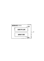
- FIG. 1 is a diagram showing an example of a functional block of the image processing system 1 according to the first embodiment of the present invention.
- the image processing system 1 includes an image coding device 100 that encodes a moving image and generates coded data, and an image decoding device 200 that decodes the coded data generated by the image coding device 100.
- the above-mentioned coded data is transmitted and received between the image coding device 100 and the image decoding device 200, for example, via a transmission line.
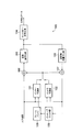
- FIG. 2 is a diagram showing an example of a functional block of the image coding device 100.
- the image coding apparatus 100 includes an inter-prediction unit 101, an intra-prediction unit 102, a conversion / quantization unit 103, an entropy coding unit 104, and an inverse conversion / inverse quantization unit 105.
- the subtraction unit 106, the addition unit 107, the in-loop filter unit 108, and the frame buffer 109 are provided.
- the inter-prediction unit 101 is configured to perform inter-prediction using the input image and the filtered locally decoded image (described later) input from the frame buffer 109 to generate and output the inter-prediction image.
- the intra prediction unit 102 is configured to perform intra prediction using an input image and a locally decoded image before filtering (described later) to generate and output an intra prediction image.
- the conversion / quantization unit 103 performs orthogonal conversion processing on the residual signal input from the subtraction unit 106, performs quantization processing on the conversion coefficient obtained by such orthogonal conversion processing, and performs such quantization processing. It is configured to output the resulting quantized level value.
- the entropy coding unit 104 is configured to entropy-encode the quantized level value and side information input from the conversion / quantization unit 103 and output it as coded data.
- the inverse conversion / inverse quantization unit 105 performs an inverse quantization process on the quantized level value input from the conversion / quantization unit 103, and with respect to the conversion coefficient obtained by the inverse quantization process. It is configured to perform the inverse orthogonal conversion process and output the inverse orthogonalized residual signal obtained by the inverse orthogonal conversion process.
- the subtraction unit 106 is configured to output a residual signal which is a difference between the input image and the intra prediction image or the inter prediction image.
- the addition unit 107 outputs a pre-filter locally decoded image obtained by adding the inverse orthogonally converted residual signal input from the inverse conversion / inverse quantization unit 105 to the intra prediction image or the inter prediction image. It is configured.
- the in-loop filter unit 108 applies in-loop filter processing such as deblocking filter processing to the pre-filter local decoding image input from the addition unit 107 to generate and output the post-filter local decoding image. It is configured.
- the frame buffer 109 accumulates the filtered locally decoded image and appropriately supplies it to the inter-prediction unit 101 as the filtered locally decoded image.
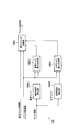
- FIG. 3 is a diagram showing an example of a functional block of the in-loop filter unit 108 of the image coding device 100 according to the present embodiment.
- the in-loop filter unit 108 of the image coding apparatus 100 includes a boundary strength calculation unit 108A, a boundary strength calculation unit 108B, a vertical weight determination unit 108C, and a horizontal weight determination unit. It includes 108D and a difference filter adding unit 108E.
- filter processing using an arbitrary filter such as a deblocking filter, an adaptive loop filter, or a sample adaptive offset filter is performed. You may.
- the pre-filter image that is the input of the in-loop filter unit 108 is the post-filter image obtained by the filter processing using another filter.
- the difference filter image input from the in-loop filter unit 108 is an image obtained by applying a model based on a difference network configuration based on CNN to the pre-filter image.
- the model is arbitrary. However, such a model is a model aimed at improving the subjective image quality of the block boundary.
- the boundary strength calculation unit 108A / 108B is configured to calculate and output the boundary strength based on the input side information.
- the boundary strength calculation unit 108A / 108B may be configured to calculate the boundary strength so as to be the same as the boundary strength in the filter processing using the existing deblocking filter.
- Such side information includes a prediction mode type that identifies an intra prediction mode, an inter prediction mode, etc., a flag indicating whether or not a nonzero coefficient exists in a block, a motion vector, and a reference image number.
- the boundary strength indicates whether or not a block boundary (edge) that is subjectively conspicuous is likely to be generated by the coding process, and is expressed in three stages of "0", "1", and "2".
- "0" indicates that there is no block boundary
- "1” indicates that there is a weak block boundary
- "2" indicates that there is a strong block boundary.
- the boundary strength calculation unit 108A / 108B is configured to set the boundary strength to "2" if the intra prediction mode is applied to at least one of the two blocks sandwiching the block boundary. Good.
- the boundary strength calculation unit 108A / 108B has a valid flag indicating whether or not a non-zero coefficient exists in at least one of the two blocks sandwiching the block boundary, and the block boundary is the boundary of the conversion block. If, the boundary strength may be configured to be set to "1".
- boundary strength calculation unit 108A / 108B is configured to set the boundary strength to "1" when the absolute value of the difference between the motion vectors of the two blocks sandwiching the block boundary is one pixel or more. Good.
- boundary strength calculation unit 108A / 108B may be configured to set the boundary strength to "1" when the reference image numbers of the motion compensation of the two blocks sandwiching the block boundary are different.
- boundary strength calculation unit 108A / 108B may be configured to set the boundary strength to "1" when the number of motion vectors for motion compensation of the two blocks sandwiching the block boundary is different.
- boundary strength calculation unit 108A / 108B may be configured to set the boundary strength to "0", except in the above cases.
- the boundary strength calculation unit 108A is configured to calculate the boundary strength related to the block boundary extending in the vertical direction
- the boundary strength calculation unit 108B calculates the boundary strength related to the block boundary extending in the horizontal direction. It is configured as follows.
- the vertical edge weight determination unit 108C and the horizontal edge weight determination unit 108D are weighting coefficients used when adding the difference filter image and the pre-filter image based on the boundary strength input from the boundary strength calculation unit 108A / 108B, respectively. This is an example of a weight determination unit configured to determine.
- the vertical edge weighting unit 108C and the horizontal edge weighting unit 108D are set to "4/4" by 4 pixels from the block boundary and 4 pixels from the vicinity of the block boundary.
- "3/4", "2/4", "1/4", etc. may be configured to determine the weighting factor.
- the vertical edge weighting unit 108C and the horizontal edge weighting unit 108D are set to "4 /" by 4 pixels from the block boundary and 4 pixels from the vicinity of the block boundary. It may be configured to determine the weighting factor, such as "8", "3/8", “2/8", "1/8".
- the vertical edge weighting unit 108C is configured to determine the weighting coefficient related to the block boundary extending in the vertical direction
- the horizontal edge weighting unit 108D determines the weighting coefficient related to the block boundary extending in the horizontal direction. It is configured to do.
- the difference filter addition unit 108E is configured to generate and output a post-filter image based on the input pre-filter image, difference filter image, and weighting coefficient.
- the difference filter addition unit 108E is configured to generate a post-filter image by multiplying the difference filter image by a weighting coefficient and then adding it to the pre-filter image.
- the boundary strength calculation unit 108A and the boundary strength calculation unit 108B are separately provided, and the vertical edge weight determination unit 108C and the horizontal edge weight determination unit 108D are separately provided.
- a boundary strength calculation unit 108AB (not shown) is provided in place of the boundary strength calculation unit 108A and the boundary strength calculation unit 108B, and the vertical edge weight determination unit 108C and the horizontal edge weight determination unit 108D are provided.
- a weight determination unit 108CD (not shown) may be provided instead of.
- the boundary strength calculation unit 108AB is configured to calculate the boundary strength of the block boundary regardless of the vertical direction and the horizontal direction
- the weight determination unit 108CD is set at the block boundary regardless of the vertical direction and the horizontal direction. It is configured to determine the weighting factor.
- the weight determination unit 108CD and the difference addition unit 108E are separately provided, but the present invention is not limited to this case, and the boundary detection unit 108F (instead of the boundary strength calculation unit 108AB) (Not shown) may be provided, and a filter correction unit 108G (not shown) may be provided instead of the weight determination unit 108CD and the difference addition unit 108E.
- the boundary detection unit 108F is configured to detect (determine) the block boundary region (edge region) regardless of the boundary strength of the block boundary, and the filter correction unit 108G determines the weighting coefficient related to the block boundary. Regardless, the pre-filter image is corrected by the difference filter image related to the block boundary region.
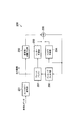
- FIG. 4 is a block diagram of the image decoding device 200 according to the present embodiment.
- the image decoding apparatus 200 includes an entropy decoding unit 201, an inverse conversion / inverse quantization unit 202, an inter prediction unit 203, an intra prediction unit 204, and an addition unit 205.
- the in-loop filter unit 206 and the frame buffer 207 are provided.
- the entropy decoding unit 201 is configured to entropy decode the encoded data and output the quantized level value and side information.
- the inverse conversion / inverse quantization unit 202 performs an inverse quantization process on the quantized level value input from the entropy decoding unit 201, and an inverse orthogonal conversion on the result obtained by the inverse quantization process. It is configured to perform processing and output as a residual signal.
- the inter-prediction unit 203 is configured to perform inter-prediction using the filtered locally decoded image input from the frame buffer 207 to generate and output the inter-prediction image.
- the intra prediction unit 204 is configured to perform intra prediction using the pre-filter locally decoded image input from the addition unit 205 to generate and output an intra prediction image.
- the addition unit 205 combines the residual signal input from the inverse transformation / inverse quantization unit 202 with the prediction image (inter prediction image input from the inter prediction unit 203 or intra prediction image input from the intra prediction unit 204). It is configured to output the pre-filter locally decoded image obtained by addition.
- the prediction image is a prediction with the highest expected coding performance obtained by entropy decoding among the inter prediction image input from the inter prediction unit 203 and the intra prediction image input from the intra prediction unit 204. It is a predicted image calculated by the method.
- the in-loop filter unit 206 is configured to apply in-loop filter processing such as deblocking filter processing to the pre-filter local decoding image input from the addition unit 205 to generate and output the post-filter local decoding image. Has been done.
- the frame buffer 207 is configured to accumulate the filtered locally decoded image input from the in-loop filter 206, appropriately supply it to the inter-prediction unit 203 as the filtered locally decoded image, and output it as a decoded image. There is.
- the in-loop filter unit 206 of the image decoding apparatus 200 includes a boundary strength calculation unit 108A, a boundary strength calculation unit 108B, a vertical weight determination unit 108C, and a horizontal weight determination unit 108D. And the difference filter adding unit 108E.
- a boundary strength calculation unit 108A a boundary strength calculation unit 108A
- a boundary strength calculation unit 108B a vertical weight determination unit 108C
- a horizontal weight determination unit 108D a horizontal weight determination unit 108D.
- the difference filter adding unit 108E the difference filter adding unit 108E.
- step S101 the in-loop filter unit 108/206 calculates the above-mentioned boundary strength based on the input side information.
- step S102 the in-loop filter unit 108/206 determines the above-mentioned weighting coefficient based on the calculated boundary strength and the pre-filter image.
- step S103 the in-loop filter unit 108/206 generates a filter image based on the input difference filter image, pre-filter image, and weighting coefficient.
- the difference filter image obtained by the filter processing of the in-loop filter method based on CNN can be appropriately corrected, and the coding performance can be improved.
- the vertical edge weighting unit 108C and the horizontal edge weighting unit 108D of the in-loop filter unit 108/206 are configured to output the above-mentioned weighting coefficient based on the input boundary strength and prediction mode. Has been done.
- the vertical edge weighting unit 108C and the horizontal edge weighting unit 108D when the boundary strength is "1" or more, for the block to which the intra prediction is applied, in order from the position closest to the block boundary.
- "4/8", “3/8", “2/8", "1/8" may be configured to determine the weighting coefficient.
- the difference filter addition unit 108E of the in-loop filter unit 108/206 generates the above-mentioned post-filter image based on the input pre-filter image, difference filter image, weighting coefficient, and quantization parameter. Is configured to output.
- the difference filter addition unit 108E determines the weighting coefficient according to the quantization parameter of the block to be processed based on the quantization parameter used for learning, and the quantization parameter for the input difference filter image. It is configured to multiply by the weighting factor determined by, multiply by the input weighting factor, add to the pre-filter image, and generate the post-filter image.
- Image processing system 100 ... Image coding devices 101, 203 ... Inter prediction unit 102, 204 ... Intra prediction unit 103 ... Conversion / quantization unit 104 ... Entropy coding unit 105, 202 ... Inverse conversion / inverse quantization unit 106 ... Subtraction units 107, 205 ... Addition units 108, 206 ... In-loop filter units 108A, 108B ... Boundary strength calculation unit 108C ... Vertical weight determination unit 108D ... Horizontal weight determination unit 108E ... Difference filter addition unit 109, 207 ... Frame buffer 200 ... Image decoding device 201 ... Entropy decoding unit
Landscapes
- Engineering & Computer Science (AREA)
- Multimedia (AREA)
- Signal Processing (AREA)
- Compression Or Coding Systems Of Tv Signals (AREA)
Abstract
画像復号装置200は、入力されたサイド情報に基づいて、ブロック境界の境界強度を算出する境界強度算出部108A/108Bと、かかる境界強度に基づいて、重み係数を決定する重み係数決定部108C/108Dと、入力された差分フィルタ画像とフィルタ前画像と重み係数とに基づいて、フィルタ後画像を生成する差分フィルタ加算部108Eとを備える。
Description
本発明は、画像復号装置、画像復号方法及びプログラムに関する。
従来、イントラ予測又はインター予測、予測残差信号の変換・量子化、エントロピー符号化を用いた画像符号化方式が提案されている(例えば、非特許文献1参照)。
かかる画像符号化方式を採用する画像符号化装置は、以下のような処理を行う。
- 入力画像を複数のブロックに分割する。
- 分割したブロック単位(1つ又は複数の変換ユニット)で、入力画像からイントラ予測画像又はインター予測画像の差分である残差信号を、変換ユニットごとに変換及び量子化してレベル値を生成する。
- 生成したレベル値をサイド情報(画素値の再構成に必要な予測モードや動きベクトル等の関連情報)と共にエントロピー符号化して符号化データを生成する。
- 入力画像を複数のブロックに分割する。
- 分割したブロック単位(1つ又は複数の変換ユニット)で、入力画像からイントラ予測画像又はインター予測画像の差分である残差信号を、変換ユニットごとに変換及び量子化してレベル値を生成する。
- 生成したレベル値をサイド情報(画素値の再構成に必要な予測モードや動きベクトル等の関連情報)と共にエントロピー符号化して符号化データを生成する。
一方、かかる画像符号化方式に対応する画像復号方式を採用する画像復号装置は、上述の画像符号化装置で行われる手順と逆の手順により、符号化データから出力画像を得る。具体的には、画像復号装置は、以下のような処理を行う。
- 符号化データから得られたレベル値を逆量子化及び逆変換して残差信号を生成する。
- かかる残差信号をイントラ予測画像又はインター予測画像に加算してフィルタ前局所復号画像を生成する。
- かかるフィルタ前局所復号画像を用いて、イントラ予測を行うと同時に、インループフィルタ(例えば、デブロックフィルタ)を適用してフィルタ後局所復号画像を生成し、フレームバッファに蓄積する。
- 符号化データから得られたレベル値を逆量子化及び逆変換して残差信号を生成する。
- かかる残差信号をイントラ予測画像又はインター予測画像に加算してフィルタ前局所復号画像を生成する。
- かかるフィルタ前局所復号画像を用いて、イントラ予測を行うと同時に、インループフィルタ(例えば、デブロックフィルタ)を適用してフィルタ後局所復号画像を生成し、フレームバッファに蓄積する。
ここで、フレームバッファは、適宜、インター予測にフィルタ後局所復号画像を供給する。
なお、符号化データからサイド情報及びレベル値を得る処理は「パース処理」と呼ばれ、かかるサイド情報及びレベル値を用いて画素値を再構成することは「復号処理」と呼ばれる。
次に、非特許文献2に記載の畳込みニューラルネットワーク(以下、CNN)に基づくインループフィルタ方式について述べる。
ここで、色形式として4:2:0を想定すると、輝度画像(Luma)及び色差画像(Chroma)の画素数は4:1:1となる。そこで、輝度4画素及び色差2画素をパッキングして6チャネルとする。
さらに、幅w、高さh、入力チャネル数c、フィルタ数fとし、「w×h×c×f」で表記されるレイヤを定義する。具体的には、「L1=3×3×6×8」、「L2=3×3×8×8」及び「L3=3×3×8×6」の3レイヤを導入する。
かかるインループフィルタ方式のフィルタ処理は、図6に示すように、以下の処理を行う。
- フィルタ前画像(輝度画像及び色差画像)をパッキングしてフィルタ前パッキング画像を得る。
- かかるフィルタ群L1~L3をフィルタ前パッキング画像に適用する。
- フィルタ後画像をアンパッキングして輝度画像及び色差画像に戻して差分フィルタ画像を得る。
- フィルタ前画像と差分フィルタ画像とを加算する。
- フィルタ前画像(輝度画像及び色差画像)をパッキングしてフィルタ前パッキング画像を得る。
- かかるフィルタ群L1~L3をフィルタ前パッキング画像に適用する。
- フィルタ後画像をアンパッキングして輝度画像及び色差画像に戻して差分フィルタ画像を得る。
- フィルタ前画像と差分フィルタ画像とを加算する。
なお、約1秒ごとに、実際に符号化された画像を用いて学習することによって、かかるフィルタL1~L3のフィルタ係数を決定する。
かかるフィルタ処理では、画像符号化装置が、符号化ブロックごとに、かかるフィルタ処理の適用の有無について判定し、フラグにより、画像復号装置に対してシグナリングする。また、学習により得られたフィルタ係数は、量子化してサイド情報として、画像符号化装置から画像復号装置にシグナリングされる。
ITU-T H.265 High Efficiency Video Coding
AHG9:Convolutional neural network loop filter、JVET-M0159v1
しかしながら、既存のCNNに基づくインループフィルタ方式のフィルタ処理では、ビットストリームから得られる予測モード等のサイド情報を利用していないため、過度にフィルタ処理が適用されて符号化性能が低下するという問題点があった。
そこで、本発明は、上述の課題に鑑みてなされたものであり、CNNに基づくインループフィルタ方式のフィルタ処理により得られた差分フィルタ画像を適切に補正することができ、符号化性能を改善することができる画像復号装置、画像復号方法及びプログラムを提供することを目的とする。
本発明の第1の特徴は、画像復号装置であって、入力されたサイド情報に基づいて、ブロック境界の境界強度を算出する境界強度算出部と、前記境界強度に基づいて、重み係数を決定する重み係数決定部と、入力された差分フィルタ画像とフィルタ前画像と前記重み係数とに基づいて、フィルタ後画像を生成する差分フィルタ加算部とを備えることを要旨とする。
本発明の第2の特徴は、画像復号方法であって、入力されたサイド情報に基づいて、ブロック境界の境界強度を算出する工程と、前記境界強度に基づいて、重み係数を決定する工程と、入力された差分フィルタ画像とフィルタ前画像と前記重み係数とに基づいて、フィルタ後画像を生成する工程とを有することを要旨とする。
本発明の第3の特徴は、コンピュータを、画像復号装置として機能させるプログラムであって、前記画像復号装置は、入力されたサイド情報に基づいて、ブロック境界の境界強度を算出する境界強度算出部と、前記境界強度に基づいて、重み係数を決定する重み係数決定部と、入力された差分フィルタ画像とフィルタ前画像と前記重み係数とに基づいて、フィルタ後画像を生成する差分フィルタ加算部とを備えることを要旨とする。
本発明によれば、CNNに基づくインループフィルタ方式のフィルタ処理により得られた差分フィルタ画像を適切に補正することができ、符号化性能を改善することができる画像復号装置、画像復号方法及びプログラムを提供することができる。
以下、本発明の実施の形態について図面を参照しながら、説明する。なお、以下の実施形態における構成要素は適宜、既存の構成要素などとの置き換えが可能であり、また、他の既存の構成要素との組み合わせを含む様々なバリエーションが可能である。したがって、以下の実施形態の記載をもって、特許請求の範囲に記載された発明の内容を限定するものではない。
(第1実施形態)
図1は、本発明の第1実施形態に係る画像処理システム1の機能ブロックの一例を示す図である。画像処理システム1は、動画像を符号化して符号化データを生成する画像符号化装置100と、画像符号化装置100により生成された符号化データを復号する画像復号装置200とを備える。画像符号化装置100と画像復号装置200との間では、上述の符号化データが、例えば、伝送路を介して送受信される。
図1は、本発明の第1実施形態に係る画像処理システム1の機能ブロックの一例を示す図である。画像処理システム1は、動画像を符号化して符号化データを生成する画像符号化装置100と、画像符号化装置100により生成された符号化データを復号する画像復号装置200とを備える。画像符号化装置100と画像復号装置200との間では、上述の符号化データが、例えば、伝送路を介して送受信される。
<画像符号化装置100>
図2は、画像符号化装置100の機能ブロックの一例を示す図である。図2に示すように、画像符号化装置100は、インター予測部101と、イントラ予測部102と、変換・量子化部103と、エントロピー符号化部104と、逆変換・逆量子化部105と、減算部106と、加算部107と、インループフィルタ部108と、フレームバッファ109とを備える。
図2は、画像符号化装置100の機能ブロックの一例を示す図である。図2に示すように、画像符号化装置100は、インター予測部101と、イントラ予測部102と、変換・量子化部103と、エントロピー符号化部104と、逆変換・逆量子化部105と、減算部106と、加算部107と、インループフィルタ部108と、フレームバッファ109とを備える。
インター予測部101は、入力画像及びフレームバッファ109から入力されるフィルタ後局所復号画像(後述)を用いて、インター予測を行ってインター予測画像を生成して出力するように構成されている。
イントラ予測部102は、入力画像及びフィルタ前局所復号画像(後述)を用いて、イントラ予測を行ってイントラ予測画像を生成して出力するように構成されている。
変換・量子化部103は、減算部106から入力される残差信号に対して直交変換処理を行い、かかる直交変換処理により得られる変換係数に対して量子化処理を行い、かかる量子化処理により得られる量子化されたレベル値を出力するように構成されている。
エントロピー符号化部104は、変換・量子化部103から入力される量子化されたレベル値及びサイド情報をエントロピー符号化して符号化データとして出力するように構成されている。
逆変換・逆量子化部105は、変換・量子化部103から入力される量子化されたレベル値に対して逆量子化処理を行い、かかる逆量子化処理により得られた変換係数に対して逆直交変換処理を行い、かかる逆直交変換処理により得られる逆直交変換された残差信号を出力するように構成されている。
減算部106は、入力画像とイントラ予測画像或いはインター予測画像との差分である残差信号を出力するように構成されている。
加算部107は、逆変換・逆量子化部105から入力される逆直交変換された残差信号とイントラ予測画像或いはインター予測画像とを加算して得られるフィルタ前局所復号画像を出力するように構成されている。
インループフィルタ部108は、加算部107から入力されるフィルタ前局所復号画像に対して、デブロッキングフィルタ処理等のインループフィルタ処理を適用してフィルタ後局所復号画像を生成して出力するように構成されている。
フレームバッファ109は、フィルタ後局所復号画像を蓄積し、適宜、フィルタ後局所復号画像としてインター予測部101に供給する。
以下、図3を参照して、本実施形態に係る画像符号化装置100のインループフィルタ部108について説明する。図3は、本実施形態に係る画像符号化装置100のインループフィルタ部108の機能ブロックの一例を示す図である。
図3に示すように、本実施形態に係る画像符号化装置100のインループフィルタ部108は、境界強度算出部108Aと、境界強度算出部108Bと、垂直重み決定部108Cと、水平重み決定部108Dと、差分フィルタ加算部108Eとを備える。
また、インループフィルタ部108の入力の前段階或いはインループフィルタ部108の出力の後段階において、デブロッキングフィルタや適応ループフィルタやサンプル適応オフセットフィルタ等の任意のフィルタを用いたフィルタ処理が行われてもよい。
すなわち、インループフィルタ部108の入力であるフィルタ前画像は、他のフィルタ用いたフィルタ処理により得られたフィルタ後画像である。
また、インループフィルタ部108の入力である差分フィルタ画像は、CNNに基づく差分ネットワーク構成によるモデルをフィルタ前画像に適用して得られた画像である。なお、かかるモデルは、任意である。ただし、かかるモデルは、ブロック境界の主観画質を改善することを目的としたモデルである。
境界強度算出部108A/108Bは、入力されたサイド情報に基づいて、境界強度を算出して出力するように構成されている。
ここで、境界強度算出部108A/108Bは、既存のデブロッキングフィルタを用いたフィルタ処理における境界強度と同一となるように、かかる境界強度を算出するように構成されていてもよい。
なお、かかるサイド情報は、イントラ予測モードやインター予測モード等を識別する予測モード種別や、ブロック内に非ゼロ係数が存在するか否かについて表すフラグや、動きベクトルや、参照画像番号を含む。
また、境界強度は、符号化処理により主観的に目立つブロック境界(エッジ)が生じやすいかどうかについて表しており、「0」、「1」、「2」の3段階で表される。ここで、「0」は、ブロック境界が無いことを示し、「1」は、弱いブロック境界があることを示し、「2」は、強いブロック境界があることを示す。
例えば、境界強度算出部108A/108Bは、ブロック境界を挟む2つのブロックにおいて少なくとも一方のブロックにイントラ予測モードが適用されていれば、境界強度を「2」に設定するように構成されていてもよい。
また、境界強度算出部108A/108Bは、ブロック境界を挟む2つのブロックにおいて少なくとも片方のブロック内に非ゼロ係数が存在するかについて表すフラグが有効であり、且つ、かかるブロック境界が変換ブロックの境界である場合、境界強度を「1」に設定するように構成されていてもよい。
また、境界強度算出部108A/108Bは、ブロック境界を挟む2つのブロックの動きベクトルの差の絶対値が1画素以上である場合、境界強度を「1」に設定するように構成されていてもよい。
また、境界強度算出部108A/108Bは、ブロック境界を挟む2つのブロックの動き補償の参照画像番号が異なる場合、境界強度を「1」に設定するように構成されていてもよい。
また、境界強度算出部108A/108Bは、ブロック境界を挟む2つのブロックの動き補償の動きベクトルの数が異なる場合、境界強度を「1」に設定するように構成されていてもよい。
なお、境界強度算出部108A/108Bは、上述の場合以外には、境界強度を「0」に設定するように構成されていてもよい。
ここで、境界強度算出部108Aは、垂直方向に延びるブロック境界に係る境界強度を算出するように構成されており、境界強度算出部108Bは、水平方向に延びるブロック境界に係る境界強度を算出するように構成されている。
垂直エッジ重み決定部108C及び水平エッジ重み決定部108Dは、それぞれ境界強度算出部108A/108Bから入力された境界強度に基づいて、差分フィルタ画像とフィルタ前画像とを加算する際に用いられる重み係数を決定するように構成されている重み決定部の一例である。
例えば、垂直エッジ重み決定部108C及び水平エッジ重み決定部108Dは、境界強度が「2」である場合、ブロック境界から4画素ずつに、ブロック境界に近いところから4画素ずつに、「4/4」、「3/4」、「2/4」、「1/4」というように、重み係数を決定するように構成されていてもよい。
同様に、垂直エッジ重み決定部108C及び水平エッジ重み決定部108Dは、境界強度が「1」である場合、ブロック境界から4画素ずつに、ブロック境界に近いところから4画素ずつに、「4/8」、「3/8」、「2/8」、「1/8」というように、重み係数を決定するように構成されていてもよい。
なお、垂直エッジ重み決定部108Cは、垂直方向に延びるブロック境界に係る重み係数を決定するように構成されており、水平エッジ重み決定部108Dは、水平方向に延びるブロック境界に係る重み係数を決定するように構成されている。
差分フィルタ加算部108Eは、入力されたフィルタ前画像と差分フィルタ画像と重み係数とに基づいて、フィルタ後画像を生成して出力するように構成されている。
具体的には、差分フィルタ加算部108Eは、差分フィルタ画像に対して重み係数を乗算した後、フィルタ前画像に加算することによって、フィルタ後画像を生成するように構成されている。
なお、本実施形態では、境界強度算出部108Aと境界強度算出部108Bとが別々に設けられ、垂直エッジ重み決定部108Cと水平エッジ重み決定部108Dとが別々に設けられているが、本発明は、かかるケースに限定されず、境界強度算出部108A及び境界強度算出部108Bの代わりに境界強度算出部108AB(図示せず)が設けられ、垂直エッジ重み決定部108C及び水平エッジ重み決定部108Dの代わりに重み決定部108CD(図示せず)が設けられていてもよい。
かかる場合、境界強度算出部108ABは、垂直方向及び水平方向に関わらずブロック境界の境界強度を算出するように構成されており、重み決定部108CDは、垂直方向及び水平方向に関わらずブロック境界に係る重み係数を決定するように構成されている。
なお、本実施形態では、重み決定部108CDと差分加算部108Eとが別々に設けられているが、本発明は、かかるケースに限定されず、境界強度算出部108ABの代わりに境界検出部108F(図示せず)が設けられ、重み決定部108CD及び差分加算部108Eの代わりにフィルタ補正部108G(図示せず)が設けられていてもよい。
かかる場合、境界検出部108Fは、ブロック境界の境界強度に関わらずブロック境界領域(エッジ領域)を検出(決定)するように構成されており、フィルタ補正部108Gは、ブロック境界に係る重み係数に関わらずブロック境界領域に係る差分フィルタ画像によってフィルタ前画像を補正するように構成されている。
<画像復号装置200>
図4は、本実施形態に係る画像復号装置200のブロック図である。図3に示すように、本実施形態に係る画像復号装置200は、エントロピー復号部201と、逆変換・逆量子化部202と、インター予測部203と、イントラ予測部204と、加算部205と、インループフィルタ部206と、フレームバッファ207とを備える。
図4は、本実施形態に係る画像復号装置200のブロック図である。図3に示すように、本実施形態に係る画像復号装置200は、エントロピー復号部201と、逆変換・逆量子化部202と、インター予測部203と、イントラ予測部204と、加算部205と、インループフィルタ部206と、フレームバッファ207とを備える。
エントロピー復号部201は、符号化データをエントロピー復号し、量子化されたレベル値や、サイド情報を出力するように構成されている。
逆変換・逆量子化部202は、エントロピー復号部201から入力される量子化されたレベル値に対して逆量子化処理を行い、かかる逆量子化処理により得られた結果に対して逆直交変換処理を行って残差信号として出力するように構成されている。
インター予測部203は、フレームバッファ207から入力されるフィルタ後局所復号画像を用いて、インター予測を行ってインター予測画像を生成して出力するように構成されている。
イントラ予測部204は、加算部205から入力されるフィルタ前局所復号画像を用いて、イントラ予測を行ってイントラ予測画像を生成して出力するように構成されている。
加算部205は、逆変換・逆量子化部202から入力される残差信号と予測画像(インター予測部203から入力されるインター予測画像或いはイントラ予測部204から入力されるイントラ予測画像)とを加算して得られるフィルタ前局所復号画像を出力するように構成されている。
ここで、予測画像とは、インター予測部203から入力されるインター予測画像及びイントラ予測部204から入力されるイントラ予測画像のうち、エントロピー復号により得られた最も高い符号化性能の期待される予測方法により算出された予測画像のことである。
インループフィルタ部206は、加算部205から入力されるフィルタ前局所復号画像に対してデブロックフィルタ処理等のインループフィルタ処理を適用してフィルタ後局所復号画像を生成して出力するように構成されている。
フレームバッファ207は、インループフィルタ206から入力されるフィルタ後局所復号画像を蓄積し、適宜、フィルタ後局所復号画像としてインター予測部203に供給するとともに、復号済み画像として出力するように構成されている。
図3に示すように、本実施形態に係る画像復号装置200のインループフィルタ部206は、境界強度算出部108Aと、境界強度算出部108Bと、垂直重み決定部108Cと、水平重み決定部108Dと、差分フィルタ加算部108Eとを備える。ここで、インループフィルタ部206の各機能は、上述のインループフィルタ部108の各機能と統一であるため、説明を省略する。
以下、図5を参照して、本実施形態に係るインループフィルタ部108/206の動作の一例について説明する。
図5に示すように、ステップS101において、インループフィルタ部108/206は、入力されたサイド情報に基づいて、上述の境界強度を算出する。
ステップS102において、インループフィルタ部108/206は、算出された境界強度及びフィルタ前画像に基づいて、上述の重み係数を決定する。
ステップS103において、インループフィルタ部108/206は、入力された差分フィルタ画像、フィルタ前画像及び重み係数に基づいて、フィルタ画像を生成する。
本実施形態に係る画像処理システム1によれば、CNNに基づくインループフィルタ方式のフィルタ処理により得られた差分フィルタ画像を適切に補正することができ、符号化性能を改善することができる。
(第2実施形態)
以下、本発明の第2実施形態に係る画像処理システム1について、上述の第1実施形態に係る画像処理システム1との相違点に着目して説明する。
以下、本発明の第2実施形態に係る画像処理システム1について、上述の第1実施形態に係る画像処理システム1との相違点に着目して説明する。
本実施形態において、インループフィルタ部108/206の垂直エッジ重み決定部108C及び水平エッジ重み決定部108Dは、入力された境界強度及び予測モードに基づいて、上述の重み係数を出力するように構成されている。
例えば、垂直エッジ重み決定部108C及び水平エッジ重み決定部108Dは、かかる境界強度が「1」以上である場合に、イントラ予測が適用されているブロックに対しては、ブロック境界に近いところから順に、「4/4」、「3/4」、「2/4」、「1/4」と重み係数を決め、インター予測が適用されているブロックに対しては、ブロック境界に近いところから順に、「4/8」、「3/8」、「2/8」、「1/8」と重み係数を決めるように構成されていてもよい。
(第3実施形態)
以下、本発明の第3実施形態に係る画像処理システム1について、上述の第1実施形態に係る画像処理システム1との相違点に着目して説明する。
以下、本発明の第3実施形態に係る画像処理システム1について、上述の第1実施形態に係る画像処理システム1との相違点に着目して説明する。
本実施形態において、インループフィルタ部108/206の差分フィルタ加算部108Eは、入力されたフィルタ前画像と差分フィルタ画像と重み係数と量子化パラメータとに基づいて、上述のフィルタ後画像を生成して出力するように構成されている。
具体的には、差分フィルタ加算部108Eは、学習に利用した量子化パラメータを基準として処理対象ブロックの量子化パラメータに応じた重み係数を決定し、入力された差分フィルタ画像に対して量子化パラメータにより決定した重み係数を乗算し、入力された重み係数を乗算し、フィルタ前画像に加算し、フィルタ後画像を生成するように構成されている。
例えば、差分フィルタ加算部108Eは、量子化パラメータQP=32でモデルを学習した場合、処理対象ブロックにおいて、「QP=22」であれば「12/64」と重み係数を決定し、「QP=37」であれば「90/64」と量子化パラメータに比例した非負の重み係数を決定するように構成されていてもよい。
1…画像処理システム
100…画像符号化装置
101、203…インター予測部
102、204…イントラ予測部
103…変換・量子化部
104…エントロピー符号化部
105、202…逆変換・逆量子化部
106…減算部
107、205…加算部
108、206…インループフィルタ部
108A、108B…境界強度算出部
108C…垂直重み決定部
108D…水平重み決定部
108E…差分フィルタ加算部
109、207…フレームバッファ
200…画像復号装置
201…エントロピー復号部
100…画像符号化装置
101、203…インター予測部
102、204…イントラ予測部
103…変換・量子化部
104…エントロピー符号化部
105、202…逆変換・逆量子化部
106…減算部
107、205…加算部
108、206…インループフィルタ部
108A、108B…境界強度算出部
108C…垂直重み決定部
108D…水平重み決定部
108E…差分フィルタ加算部
109、207…フレームバッファ
200…画像復号装置
201…エントロピー復号部
Claims (6)
- 入力されたサイド情報に基づいて、ブロック境界の境界強度を算出する境界強度算出部と、
前記境界強度に基づいて、重み係数を決定する重み係数決定部と、
入力された差分フィルタ画像とフィルタ前画像と前記重み係数とに基づいて、フィルタ後画像を生成する差分フィルタ加算部とを備えることを特徴とする画像復号装置。 - 前記境界強度算出部は、前記境界強度として、垂直方向に延びるブロック境界の境界強度及び水平方向に延びる前記ブロック境界の境界強度のそれぞれを決定することを特徴とする請求項1に記載の画像復号装置。
- 前記重み係数決定部は、前記境界強度及び予測モードに基づいて、前記重み係数を決定することを特徴とする請求項1又は2に記載の画像復号装置。
- 前記差分フィルタ加算部は、前記差分フィルタ画像と前記フィルタ前画像と前記前記重み係数と量子化パラメータとに基づいて、前記フィルタ後画像を生成する請求項1~3のいずれか一項に記載の画像復号装置。
- 入力されたサイド情報に基づいて、ブロック境界の境界強度を算出する工程と、
前記境界強度に基づいて、重み係数を決定する工程と、
入力された差分フィルタ画像とフィルタ前画像と前記重み係数とに基づいて、フィルタ後画像を生成する工程とを有することを特徴とする画像復号方法。 - コンピュータを、画像復号装置として機能させるプログラムであって、
前記画像復号装置は、
入力されたサイド情報に基づいて、ブロック境界の境界強度を算出する境界強度算出部と、
前記境界強度に基づいて、重み係数を決定する重み係数決定部と、
入力された差分フィルタ画像とフィルタ前画像と前記重み係数とに基づいて、フィルタ後画像を生成する差分フィルタ加算部とを備えることを特徴とするプログラム。
Priority Applications (2)
| Application Number | Priority Date | Filing Date | Title |
|---|---|---|---|
| CN202080019690.9A CN113545071A (zh) | 2019-03-12 | 2020-03-02 | 图像解码装置、图像解码方法和程序 |
| US17/471,357 US20210409744A1 (en) | 2019-03-12 | 2021-09-10 | Image decoding device, image decoding method, and program |
Applications Claiming Priority (2)
| Application Number | Priority Date | Filing Date | Title |
|---|---|---|---|
| JP2019044644A JP7026065B2 (ja) | 2019-03-12 | 2019-03-12 | 画像復号装置、画像復号方法及びプログラム |
| JP2019-044644 | 2019-03-12 |
Related Child Applications (1)
| Application Number | Title | Priority Date | Filing Date |
|---|---|---|---|
| US17/471,357 Continuation US20210409744A1 (en) | 2019-03-12 | 2021-09-10 | Image decoding device, image decoding method, and program |
Publications (1)
| Publication Number | Publication Date |
|---|---|
| WO2020184266A1 true WO2020184266A1 (ja) | 2020-09-17 |
Family
ID=72427382
Family Applications (1)
| Application Number | Title | Priority Date | Filing Date |
|---|---|---|---|
| PCT/JP2020/008776 Ceased WO2020184266A1 (ja) | 2019-03-12 | 2020-03-02 | 画像復号装置、画像復号方法及びプログラム |
Country Status (4)
| Country | Link |
|---|---|
| US (1) | US20210409744A1 (ja) |
| JP (1) | JP7026065B2 (ja) |
| CN (1) | CN113545071A (ja) |
| WO (1) | WO2020184266A1 (ja) |
Families Citing this family (2)
| Publication number | Priority date | Publication date | Assignee | Title |
|---|---|---|---|---|
| US12423878B2 (en) * | 2021-06-16 | 2025-09-23 | Tencent America LLC | Content-adaptive online training method and apparatus for deblocking in block-wise image compression |
| US12445657B1 (en) * | 2023-07-21 | 2025-10-14 | Zoom Communications, Inc. | Deriving in-loop filter parameters for video coding |
Citations (3)
| Publication number | Priority date | Publication date | Assignee | Title |
|---|---|---|---|---|
| WO2017056665A1 (ja) * | 2015-09-30 | 2017-04-06 | Kddi株式会社 | 動画像の処理装置、処理方法及びコンピュータ可読記憶媒体 |
| WO2019031410A1 (ja) * | 2017-08-10 | 2019-02-14 | シャープ株式会社 | 画像フィルタ装置、画像復号装置、および画像符号化装置 |
| WO2019046295A1 (en) * | 2017-08-28 | 2019-03-07 | Interdigital Vc Holdings, Inc. | APPARATUS AND METHOD FOR FILTERING WITH DEPTH LEARNING IN FUNCTION MODE |
Family Cites Families (9)
| Publication number | Priority date | Publication date | Assignee | Title |
|---|---|---|---|---|
| KR100827106B1 (ko) * | 2006-10-20 | 2008-05-02 | 삼성전자주식회사 | 디블록킹 필터에서의 필터 조건 영역 판별을 위한 장치 및방법 |
| JPWO2009001793A1 (ja) * | 2007-06-26 | 2010-08-26 | 株式会社東芝 | 画像符号化と画像復号化の方法及び装置 |
| JP5014423B2 (ja) * | 2007-10-03 | 2012-08-29 | パナソニック株式会社 | ブロック歪みを減少させる方法および装置 |
| EP2157799A1 (en) * | 2008-08-18 | 2010-02-24 | Panasonic Corporation | Interpolation filter with local adaptation based on block edges in the reference frame |
| KR101963097B1 (ko) * | 2010-12-07 | 2019-03-27 | 소니 주식회사 | 화상 처리 장치 및 화상 처리 방법 |
| CN106941608B (zh) * | 2011-06-30 | 2021-01-15 | 三菱电机株式会社 | 图像编码装置及方法、图像解码装置及方法 |
| JP5913929B2 (ja) * | 2011-11-28 | 2016-05-11 | キヤノン株式会社 | 動画像符号化装置及びその制御方法、コンピュータプログラム |
| KR20130081080A (ko) * | 2012-01-06 | 2013-07-16 | 광주과학기술원 | 영상 경계 명확화 장치 및 방법 |
| TWI833248B (zh) * | 2017-04-06 | 2024-02-21 | 美商松下電器(美國)知識產權公司 | 解碼方法及編碼方法 |
-
2019
- 2019-03-12 JP JP2019044644A patent/JP7026065B2/ja active Active
-
2020
- 2020-03-02 WO PCT/JP2020/008776 patent/WO2020184266A1/ja not_active Ceased
- 2020-03-02 CN CN202080019690.9A patent/CN113545071A/zh active Pending
-
2021
- 2021-09-10 US US17/471,357 patent/US20210409744A1/en not_active Abandoned
Patent Citations (3)
| Publication number | Priority date | Publication date | Assignee | Title |
|---|---|---|---|---|
| WO2017056665A1 (ja) * | 2015-09-30 | 2017-04-06 | Kddi株式会社 | 動画像の処理装置、処理方法及びコンピュータ可読記憶媒体 |
| WO2019031410A1 (ja) * | 2017-08-10 | 2019-02-14 | シャープ株式会社 | 画像フィルタ装置、画像復号装置、および画像符号化装置 |
| WO2019046295A1 (en) * | 2017-08-28 | 2019-03-07 | Interdigital Vc Holdings, Inc. | APPARATUS AND METHOD FOR FILTERING WITH DEPTH LEARNING IN FUNCTION MODE |
Non-Patent Citations (3)
| Title |
|---|
| HUJUN YIN ET AL.: "AHG9: Adaptive convolutional neural network loop filter", JOINT VIDEO EXPERTS TEAM (JVET) OF ITU-T SG 16 WP 3 AND ISO/IEC JTC 1/SC 29/ WG 11, JVET-M0566, 13TH MEETING, January 2019 (2019-01-01), Marrakesh, pages 1 - 9 * |
| KEI KAWAMURA ET AL.: "CE13-related: Adaptive CNN based in-loop filtering with boundary weights", JOINT VIDEO EXPERTS TEAM (JVET) OF ITU-T SG 16 WP 3 AND ISO/IEC JTC 1/SC 29/WG 11, JVET-N0712, 14TH MEETING, March 2019 (2019-03-01), Geneva, CH, pages 1 - 2, XP030204016 * |
| YU-LING HSIAO ET AL.: "AHG9: Convolutional neural network loop filter", JOINT VIDEO EXPERTS TEAM (JVET) OF ITU-T SG 16 WP 3 AND ISO/IEC JTC 1/SC 29/WG 11, JVET-M0159-V1, 13TH MEETING, January 2019 (2019-01-01), Marrakech, MA, pages 1 - 6, XP030200363 * |
Also Published As
| Publication number | Publication date |
|---|---|
| JP2020150358A (ja) | 2020-09-17 |
| JP7026065B2 (ja) | 2022-02-25 |
| CN113545071A (zh) | 2021-10-22 |
| US20210409744A1 (en) | 2021-12-30 |
Similar Documents
| Publication | Publication Date | Title |
|---|---|---|
| KR102165340B1 (ko) | 색차 성분 양자화 매개 변수 결정 방법 및 이러한 방법을 사용하는 장치 | |
| JP6620354B2 (ja) | 動画像の処理装置、処理方法及びコンピュータ可読記憶媒体 | |
| KR101621854B1 (ko) | Tsm 율-왜곡 최적화 방법, 그를 이용한 인코딩 방법 및 장치, 그리고 영상 처리 장치 | |
| CN110024387A (zh) | 编码装置、解码装置、编码方法和解码方法 | |
| WO2009133844A1 (ja) | エッジを考慮したフィルタリング機能を備えた動画像符号化/復号化方法及び装置 | |
| CN105409221A (zh) | 用于样本自适应偏移滤波的编码器侧决策 | |
| US11871021B2 (en) | Moving picture decoding device, moving picture decoding method, and program obtaining chrominance values from corresponding luminance values | |
| JP7675225B2 (ja) | 画像符号化装置、画像符号化方法、画像復号装置、画像復号方法 | |
| JP7026065B2 (ja) | 画像復号装置、画像復号方法及びプログラム | |
| JP2014131162A (ja) | イントラ予測符号化方法、イントラ予測復号方法、イントラ予測符号化装置、イントラ予測復号装置、それらのプログラム並びにプログラムを記録した記録媒体 | |
| WO2021040036A1 (ja) | 符号化装置、復号装置、及びプログラム | |
| JP2022102804A (ja) | 画像復号装置、画像復号方法及びプログラム | |
| JP6839246B2 (ja) | 動画像の処理装置、処理方法及びコンピュータ可読記憶媒体 | |
| HK40095748A (zh) | 图像编码设备和方法、图像解码设备和方法以及存储介质 | |
| HK40095747A (zh) | 图像编码设备和方法、图像解码设备和方法以及存储介质 | |
| HK40095750A (zh) | 图像编码设备和方法、图像解码设备和方法以及存储介质 | |
| HK40095352A (zh) | 图像编码设备和方法、图像解码设备和方法以及存储介质 | |
| HK40095746A (zh) | 图像编码设备和方法、图像解码设备和方法以及存储介质 | |
| HK40095749A (zh) | 图像编码设备和方法、图像解码设备和方法以及存储介质 | |
| WO2021045059A1 (ja) | 符号化装置、復号装置、及びプログラム | |
| WO2021054037A1 (ja) | 画像復号装置、画像復号方法及びプログラム | |
| JP2021022887A (ja) | デブロッキングフィルタ制御装置及びプログラム |
Legal Events
| Date | Code | Title | Description |
|---|---|---|---|
| 121 | Ep: the epo has been informed by wipo that ep was designated in this application |
Ref document number: 20770011 Country of ref document: EP Kind code of ref document: A1 |
|
| NENP | Non-entry into the national phase |
Ref country code: DE |
|
| 122 | Ep: pct application non-entry in european phase |
Ref document number: 20770011 Country of ref document: EP Kind code of ref document: A1 |