WO2020184215A1 - カメラ、制御方法、及び、プログラム - Google Patents
カメラ、制御方法、及び、プログラム Download PDFInfo
- Publication number
- WO2020184215A1 WO2020184215A1 PCT/JP2020/008242 JP2020008242W WO2020184215A1 WO 2020184215 A1 WO2020184215 A1 WO 2020184215A1 JP 2020008242 W JP2020008242 W JP 2020008242W WO 2020184215 A1 WO2020184215 A1 WO 2020184215A1
- Authority
- WO
- WIPO (PCT)
- Prior art keywords
- image
- bit rate
- camera
- coding
- control unit
- Prior art date
- Legal status (The legal status is an assumption and is not a legal conclusion. Google has not performed a legal analysis and makes no representation as to the accuracy of the status listed.)
- Ceased
Links
Images


Classifications
-
- H—ELECTRICITY
- H04—ELECTRIC COMMUNICATION TECHNIQUE
- H04N—PICTORIAL COMMUNICATION, e.g. TELEVISION
- H04N23/00—Cameras or camera modules comprising electronic image sensors; Control thereof
- H04N23/60—Control of cameras or camera modules
- H04N23/68—Control of cameras or camera modules for stable pick-up of the scene, e.g. compensating for camera body vibrations
- H04N23/682—Vibration or motion blur correction
- H04N23/683—Vibration or motion blur correction performed by a processor, e.g. controlling the readout of an image memory
-
- H—ELECTRICITY
- H04—ELECTRIC COMMUNICATION TECHNIQUE
- H04N—PICTORIAL COMMUNICATION, e.g. TELEVISION
- H04N19/00—Methods or arrangements for coding, decoding, compressing or decompressing digital video signals
- H04N19/10—Methods or arrangements for coding, decoding, compressing or decompressing digital video signals using adaptive coding
- H04N19/102—Methods or arrangements for coding, decoding, compressing or decompressing digital video signals using adaptive coding characterised by the element, parameter or selection affected or controlled by the adaptive coding
- H04N19/115—Selection of the code volume for a coding unit prior to coding
-
- H—ELECTRICITY
- H04—ELECTRIC COMMUNICATION TECHNIQUE
- H04N—PICTORIAL COMMUNICATION, e.g. TELEVISION
- H04N19/00—Methods or arrangements for coding, decoding, compressing or decompressing digital video signals
- H04N19/10—Methods or arrangements for coding, decoding, compressing or decompressing digital video signals using adaptive coding
- H04N19/134—Methods or arrangements for coding, decoding, compressing or decompressing digital video signals using adaptive coding characterised by the element, parameter or criterion affecting or controlling the adaptive coding
- H04N19/136—Incoming video signal characteristics or properties
- H04N19/137—Motion inside a coding unit, e.g. average field, frame or block difference
-
- H—ELECTRICITY
- H04—ELECTRIC COMMUNICATION TECHNIQUE
- H04N—PICTORIAL COMMUNICATION, e.g. TELEVISION
- H04N19/00—Methods or arrangements for coding, decoding, compressing or decompressing digital video signals
- H04N19/10—Methods or arrangements for coding, decoding, compressing or decompressing digital video signals using adaptive coding
- H04N19/169—Methods or arrangements for coding, decoding, compressing or decompressing digital video signals using adaptive coding characterised by the coding unit, i.e. the structural portion or semantic portion of the video signal being the object or the subject of the adaptive coding
- H04N19/17—Methods or arrangements for coding, decoding, compressing or decompressing digital video signals using adaptive coding characterised by the coding unit, i.e. the structural portion or semantic portion of the video signal being the object or the subject of the adaptive coding the unit being an image region, e.g. an object
- H04N19/172—Methods or arrangements for coding, decoding, compressing or decompressing digital video signals using adaptive coding characterised by the coding unit, i.e. the structural portion or semantic portion of the video signal being the object or the subject of the adaptive coding the unit being an image region, e.g. an object the region being a picture, frame or field
-
- H—ELECTRICITY
- H04—ELECTRIC COMMUNICATION TECHNIQUE
- H04N—PICTORIAL COMMUNICATION, e.g. TELEVISION
- H04N23/00—Cameras or camera modules comprising electronic image sensors; Control thereof
- H04N23/60—Control of cameras or camera modules
- H04N23/68—Control of cameras or camera modules for stable pick-up of the scene, e.g. compensating for camera body vibrations
- H04N23/681—Motion detection
- H04N23/6811—Motion detection based on the image signal
-
- H—ELECTRICITY
- H04—ELECTRIC COMMUNICATION TECHNIQUE
- H04N—PICTORIAL COMMUNICATION, e.g. TELEVISION
- H04N23/00—Cameras or camera modules comprising electronic image sensors; Control thereof
- H04N23/60—Control of cameras or camera modules
- H04N23/68—Control of cameras or camera modules for stable pick-up of the scene, e.g. compensating for camera body vibrations
- H04N23/681—Motion detection
- H04N23/6812—Motion detection based on additional sensors, e.g. acceleration sensors
-
- H—ELECTRICITY
- H04—ELECTRIC COMMUNICATION TECHNIQUE
- H04N—PICTORIAL COMMUNICATION, e.g. TELEVISION
- H04N23/00—Cameras or camera modules comprising electronic image sensors; Control thereof
- H04N23/60—Control of cameras or camera modules
- H04N23/68—Control of cameras or camera modules for stable pick-up of the scene, e.g. compensating for camera body vibrations
- H04N23/681—Motion detection
- H04N23/6815—Motion detection by distinguishing pan or tilt from motion
-
- H—ELECTRICITY
- H04—ELECTRIC COMMUNICATION TECHNIQUE
- H04N—PICTORIAL COMMUNICATION, e.g. TELEVISION
- H04N23/00—Cameras or camera modules comprising electronic image sensors; Control thereof
- H04N23/60—Control of cameras or camera modules
- H04N23/68—Control of cameras or camera modules for stable pick-up of the scene, e.g. compensating for camera body vibrations
- H04N23/682—Vibration or motion blur correction
- H04N23/685—Vibration or motion blur correction performed by mechanical compensation
- H04N23/687—Vibration or motion blur correction performed by mechanical compensation by shifting the lens or sensor position
-
- H—ELECTRICITY
- H04—ELECTRIC COMMUNICATION TECHNIQUE
- H04N—PICTORIAL COMMUNICATION, e.g. TELEVISION
- H04N23/00—Cameras or camera modules comprising electronic image sensors; Control thereof
- H04N23/80—Camera processing pipelines; Components thereof
Definitions
- the present technology relates to cameras, control methods, and programs, and in particular, to, for example, cameras, control methods, and programs that enable improvement in image quality.
- Patent Document 1 An imaging device that changes the coding characteristics according to shooting operations such as zoom, pan, and fade has been proposed (see, for example, Patent Document 1).
- an image (moving image) is captured, encoded, and stored (recorded).
- image coding moving images are assigned many bit rates.
- Cases where the image is moving include cases where the subject in the image is moving, cases where the user is intentionally panning or tilting the digital camera, and cases where the user is not intentionally operating the camera shake.
- the digital camera is shaken (hereinafter, also referred to as camera shake) due to such factors.
- the image taken when the camera shake occurs is an image whose image quality has deteriorated due to the camera shake, and it is not necessary to allocate a large bit rate.
- the bit rate that can be assigned to an image that originally wants to improve the image quality decreases, or the image quality is originally improved. It takes time before a sufficient bit rate can be assigned to the desired image, and the image quality may deteriorate due to codec noise caused by coding.
- This technology was made in view of such a situation, and makes it possible to improve the image quality.
- the camera of the present technology includes an image sensor that captures an image, a coding unit that encodes the image, and a control unit that controls the bit rate assigned to the coding of the image according to the camera shake. Is.
- the control method or program of the present technology controls the bit rate assigned to the coding of the image according to the blurring of the camera including the image sensor that captures the image and the coding unit that encodes the image. It is a control method of a camera including the above, or a program for causing a computer to execute such a control method.
- the bit rate assigned to the coding of the image is controlled according to the camera shake.
- the camera may be an independent device or an internal block constituting one device.
- the program can be provided by transmitting via a transmission medium or by recording on a recording medium.
- FIG. 1 is a block diagram showing a configuration example of an embodiment of a digital camera to which the present technology is applied.
- the digital camera has an optical system 11, an image sensor 12, an A / D (Analog to Digital) conversion unit 13, a signal processing unit 14, a coding unit 15, a memory 16, and a control unit 17.
- a / D Analog to Digital
- the optical system 11 is composed of optical components such as a lens and an aperture, and collects light from a subject on an image sensor 12.
- the image sensor 12 captures an image that receives light from the optical system 11 and performs photoelectric conversion at a predetermined frame rate, and obtains a captured image (signal) by the imaging in the A / D conversion unit 13. Output to.
- the signal processing unit 14 performs signal processing for improving the image quality such as white balance adjustment and noise removal, and other signal processing on the captured image from the A / D conversion unit 13, and outputs the image to the coding unit 15. ..
- the coding unit 15 encodes (compresses) the captured image from the signal processing unit 14 according to a predetermined coding method such as an MPEG method (MPEG2, AVC (Advanced Video Coding), etc.), and the code obtained as a result.
- MPEG Motion Picture Experts Group
- AVC Advanced Video Coding
- the memory 16 stores the coded data from the coding unit 15.
- the control unit 17 controls the optical system 11, the image sensor 12, the signal processing unit 14, and the coding unit 15.
- control unit 17 adjusts the aperture, focus, zoom, etc. by controlling the optical system 11. Further, the control unit 17 adjusts the exposure time and the like by controlling the image sensor 12. Further, the control unit 17 controls the signal processing unit 14 to switch the signal processing performed by the signal processing unit 14.
- control unit 17 controls the bit rate (the amount of coded data after coding of the captured image) assigned to the coding of the captured image in the coding unit 15 according to the camera shake (blur of the digital camera). To do.
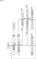
- FIG. 2 is a flowchart illustrating an example of bit rate control processing by the control unit 17.
- step S11 the control unit 17 determines whether or not there is a captured image to be encoded by the coding unit 15, and if it is determined that there is no captured image to be encoded, the process ends. .. If it is determined in step S11 that there is a captured image to be encoded, the process proceeds to step S12.
- step S12 the control unit 17 determines whether or not the captured image to be encoded has motion.
- step S12 If it is determined in step S12 that the captured image to be encoded does not move, the process proceeds to step S13.
- step S13 the control unit 17 performs normal bit rate allocation control for controlling the bit rate so that the bit rate is assigned according to the definition of the coding method of the coding unit 15, and the process returns to step S11.
- the coding unit 15 encodes the captured image by allocating the bit rate according to the definition of the coding method of the coding unit 15 according to the normal bit rate allocation control of the control unit 17.
- step S12 determines whether the captured image to be encoded has motion. If it is determined in step S12 that the captured image to be encoded has motion, the process proceeds to step S14.
- step S14 the control unit 17 determines whether or not the subject reflected in the captured image is moving, and if it is determined that the subject reflected in the captured image is moving, the process proceeds to step S13, and the above-described process is performed. It is said.
- step S14 if it is determined that the subject reflected in the captured image is not moving, that is, if the movement of the captured image is caused by the movement of the digital camera, the process proceeds to step S15.
- step S15 the control unit 17 determines whether or not the digital camera is intentionally moved.
- step S15 If it is determined in step S15 that the digital camera is intentionally moved, that is, if the user is performing an operation such as panning or tilting to intentionally move the digital camera, the process is performed in step S13. The process described above is performed.
- step S15 if it is determined that the digital camera is not intentionally moved, that is, if the captured image is moving due to camera shake, the process proceeds to step S16.
- step S16 the control unit 17 performs bit rate allocation suppression control for controlling the bit rate so that the bit rate assigned to the coding of the captured image is suppressed rather than the normal bit rate allocation control, and the process is performed.
- the coding unit 15 suppresses the bit rate assigned to the coding of the captured image according to the bit rate allocation suppression control of the control unit 17 rather than the normal bit rate allocation control.
- steps S12, S14, and S15 is based on the motion vector detected from the captured image for motion compensation and the acceleration sensor provided in the optical system 11, the image sensor 12, etc. for camera shake correction. This can be done using the output (motion vector as) or the like.
- control unit 17 can suppress the bit rate assigned to the coding of the captured image as the camera shake increases according to the magnitude of the camera shake.
- control unit 17 stores motion vectors representing the magnitude and direction of camera shake for a certain period or more, and performs bit rate allocation suppression control when camera shake of a predetermined size or more continues for a certain period or more. It can be carried out.
- bit rate allocation suppression control is not performed only when the camera shake occurs momentarily, and the bit rate allocation suppression control can be performed only when the camera shake continues for a certain period or more.
- control unit 17 can control the bit rate assigned to the coding of the captured image and also control the signal processing of the signal processing unit 14 according to the camera shake. For example, in the signal processing unit 14, when there is no camera shake, signal processing for image sharpening such as edge enhancement is performed, and when there is camera shake, a signal for smoothing such as noise removal is performed. The processing can be performed.
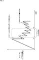
- FIG. 3 is a diagram illustrating an example of bit rate allocation performed according to the definition of the coding method of the coding unit 15.
- the vertical axis represents the amount of the decoder buffer (decoder buffer) used to decode the encoded data
- the horizontal axis represents time
- the coded data is written at a constant rate, and the coded data is read out one picture at a time in a cycle corresponding to the frame rate.
- the portion where the usage amount of the decoder buffer is significantly reduced indicates that a large number of bit rates are allocated, and the portion where the usage amount of the decoder buffer is small and decreased is a small bit rate. Indicates that is assigned.
- the coding unit 15 allocates the bit rate within a range in which overflow and underflow of the decoder buffer do not occur. Further, in the bit rate allocation performed according to the definition of the coding method of the coding unit 15, in principle, a larger number of bit rates are assigned in order to improve the image quality as the captured image (picture) has a movement.
- Fig. 3 camera shake occurs between times t1 and t2. Then, according to FIG. 3, in the bit rate allocation performed according to the definition of the coding method of the coding unit 15, a relatively large number of bit rates are allocated during the period when the camera shake occurs, and as a result, the camera It can be confirmed that the bit rate assigned immediately after the blurring has subsided is suppressed. In this case, the image quality of the captured image immediately after the camera shake has subsided may deteriorate.
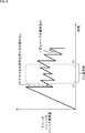
- FIG. 4 is a diagram illustrating an example of bit rate allocation performed according to the control of the control unit 17.
- the vertical axis represents the usage amount of the decoder buffer
- the horizontal axis represents time
- control unit 17 distinguishes whether or not the captured image is camera shake (whether or not the subject is moving and whether or not the digital camera is intentionally moved), and the captured image is captured.
- the movement of the camera is camera shake, the bit rate is suppressed, so that the image quality can be improved.
- the series of processes of the control unit 17 described above can be performed by hardware or software.
- the programs constituting the software are installed on the computer.
- FIG. 5 is a block diagram showing a configuration example of an embodiment of a computer on which a program for executing the above-mentioned series of processes is installed.
- the program can be recorded in advance on the hard disk 905 or ROM 903 as a recording medium built in the computer.
- the program can be stored (recorded) in the removable recording medium 911 driven by the drive 909.
- a removable recording medium 911 can be provided as so-called package software.
- examples of the removable recording medium 911 include a flexible disk, a CD-ROM (Compact Disc Read Only Memory), an MO (Magneto Optical) disk, a DVD (Digital Versatile Disc), a magnetic disk, and a semiconductor memory.
- the program can be downloaded to the computer via a communication network or a broadcasting network and installed on the built-in hard disk 905. That is, for example, the program transfers wirelessly from a download site to a computer via an artificial satellite for digital satellite broadcasting, or transfers to a computer by wire via a network such as LAN (Local Area Network) or the Internet. be able to.
- LAN Local Area Network
- the computer has a built-in CPU (Central Processing Unit) 902, and the input / output interface 910 is connected to the CPU 902 via the bus 901.
- CPU Central Processing Unit
- the CPU 902 executes a program stored in the ROM (Read Only Memory) 903 accordingly. .. Alternatively, the CPU 902 loads the program stored in the hard disk 905 into the RAM (Random Access Memory) 904 and executes it.
- ROM Read Only Memory
- the CPU 902 performs processing according to the above-mentioned flowchart or processing performed according to the above-mentioned block diagram configuration. Then, the CPU 902 outputs the processing result from the output unit 906, transmits it from the communication unit 908, and records it on the hard disk 905, if necessary, via, for example, the input / output interface 910.
- the input unit 907 is composed of a keyboard, a mouse, a microphone, and the like. Further, the output unit 906 is composed of an LCD (Liquid Crystal Display), a speaker, or the like.
- LCD Liquid Crystal Display
- the processing performed by the computer according to the program does not necessarily have to be performed in chronological order in the order described as the flowchart. That is, the processing performed by the computer according to the program also includes processing executed in parallel or individually (for example, parallel processing or processing by an object).
- the program may be processed by one computer (processor) or may be distributed by a plurality of computers. Further, the program may be transferred to a distant computer and executed.
- the system means a set of a plurality of constituent elements (devices, modules (parts), etc.), and it does not matter whether or not all constituent elements are in the same housing. Therefore, a plurality of devices housed in separate housings and connected via a network, and a device in which a plurality of modules are housed in one housing are both systems. ..
- this technology can have a cloud computing configuration in which one function is shared by a plurality of devices via a network and processed jointly.
- each step described in the above flowchart can be executed by one device or can be shared and executed by a plurality of devices.
- one step includes a plurality of processes
- the plurality of processes included in the one step can be executed by one device or shared by a plurality of devices.
- An image sensor that captures images and A coding unit that encodes the image and A camera including a control unit that controls a bit rate assigned to the coding of the image according to the camera shake.
- the control unit suppresses the bit rate assigned to the coding of the image as the camera shake increases.
- the control unit suppresses a bit rate assigned to coding the image when the camera shake continues for a certain period of time or longer.
- the control unit When there is no blurring of the camera, normal bit rate allocation control for controlling the bit rate is performed so that the bit rate is assigned according to the definition of the coding method of the coding unit.
- bit rate allocation suppression control for controlling the bit rate is performed so that the bit rate assigned to the coding of the image is suppressed more than the normal bit rate allocation control ⁇ 1> to The camera described in ⁇ 3>.
- a signal processing unit that performs signal processing of the image is further provided. The camera according to ⁇ 1> to ⁇ 4>, wherein the control unit controls the signal processing according to the camera shake.
- An image sensor that captures images and A method for controlling a camera which comprises controlling the bit rate assigned to the coding of the image according to the blurring of the camera including the coding unit for encoding the image.
Landscapes
- Engineering & Computer Science (AREA)
- Multimedia (AREA)
- Signal Processing (AREA)
- Studio Devices (AREA)
- Compression Or Coding Systems Of Tv Signals (AREA)
Abstract
本技術は、画質を改善することができるようにするカメラ、制御方法、及び、プログラムに関する。 イメージセンサは、画像を撮影し、符号化部は、画像を符号化する。制御部は、カメラのぶれに応じて、画像の符号化に割り当てるビットレートを制御する。本技術は、例えば、画像を撮影して符号化するカメラに適用することができる。
Description
本技術は、カメラ、制御方法、及び、プログラムに関し、特に、例えば、画質を改善することができるようにするカメラ、制御方法、及び、プログラムに関する。
例えば、ズーム、パン、フェード等の撮影操作に応じ、符号化特性を変化させる撮像装置が提案されている(例えば、特許文献1を参照)。
例えば、ディジタルカメラでは、画像(動画)が撮影され、符号化されて記憶(記録)される。画像の符号化では、動きのある画像に、多くのビットレートが割り当てられる。
画像に動きがあるケースとしては、画像に映る被写体が動いているケース、ユーザが意図的な操作としてのディジタルカメラのパンやチルト等を行っているケース、及び、ユーザの意図的な操作でない手ぶれ等によりディジタルカメラのぶれ(以下、カメラぶれともいう)が生じているケースがある。
したがって、被写体が動いている画像、及び、パンやチルト等を行いながら撮影された画像の他、カメラぶれが生じているときに撮影された画像にも、多くのビットレートが割り当てられる。
しかしながら、カメラぶれが生じているときに撮影された画像は、カメラぶれに起因して画質が劣化した画像になっており、多くのビットレートを割り当てる必要がない。さらに、カメラぶれが生じているときに撮影された画像に多くのビットレートが割り当てられることにより、本来、画質を良くしたい画像に割り当てることができるビットレートが少なくなり、又は、本来、画質を良くしたい画像に十分なビットレートを割り当てることができるまでに時間を要し、画像に、符号化に起因するコーディックノイズがのって、画質が劣化することがある。
本技術は、このような状況に鑑みてなされたものであり、画質を改善することができるようにするものである。
本技術のカメラは、画像を撮影するイメージセンサと、前記画像を符号化する符号化部と、カメラのぶれに応じて、前記画像の符号化に割り当てるビットレートを制御する制御部とを備えるカメラである。
本技術の制御方法、又は、プログラムは、画像を撮影するイメージセンサと、前記画像を符号化する符号化部とを備えるカメラのぶれに応じて、前記画像の符号化に割り当てるビットレートを制御することを含むカメラの制御方法、又は、そのような制御方法をコンピュータに実行させるためのプログラムである。
本技術においては、カメラのぶれに応じて、前記画像の符号化に割り当てるビットレートが制御される。
なお、カメラは、独立した装置であっても良いし、1つの装置を構成している内部ブロックであっても良い。
また、プログラムは、伝送媒体を介して伝送することにより、又は、記録媒体に記録して、提供することができる。
<本技術を適用したディジタルカメラ>
図1は、本技術を適用したディジタルカメラの一実施の形態の構成例を示すブロック図である。
図1において、ディジタルカメラは、光学系11、イメージセンサ12、A/D(Analog to Digital)変換部13、信号処理部14、符号化部15、メモリ16、及び、制御部17を有する。
光学系11は、レンズや絞り等の光学部品で構成され、被写体からの光を、イメージセンサ12に集光する。
イメージセンサ12は、光学系11からの光を受光して光電変換を行う画像の撮影を、所定のフレームレートで行い、その撮影により得られる撮影画像(の信号)を、A/D変換部13に出力する。
A/D変換部13は、イメージセンサ12からの撮影画像をA/D変換し、信号処理部14に供給する。
信号処理部14は、A/D変換部13からの撮影画像に、ホワイトバランスの調整、ノイズ除去等の高画質化のための信号処理、その他の信号処理を行い、符号化部15に出力する。
符号化部15は、信号処理部14からの撮影画像を、MPEG方式(MPEG2や、AVC(Advanced Video Coding)等)等の所定の符号化方式に従って符号化(圧縮)し、その結果得られる符号化データを、メモリ16に供給する。
メモリ16は、符号化部15からの符号化データを記憶する。
制御部17は、光学系11や、イメージセンサ12、信号処理部14、符号化部15を制御する。
例えば、制御部17は、光学系11を制御することにより、絞りや、フォーカス、ズーム等を調整する。また、制御部17は、イメージセンサ12を制御することにより、露光時間等を調整する。さらに、制御部17は、信号処理部14を制御することにより、信号処理部14で行われる信号処理を切り替える。
また、制御部17は、カメラぶれ(ディジタルカメラのぶれ)に応じて、符号化部15において撮影画像の符号化に割り当てるビットレート(撮影画像の符号化後の符号化データのデータ量)を制御する。
<制御部17の処理>
図2は、制御部17によるビットレートの制御の処理の例を説明するフローチャートである。
ステップS11において、制御部17は、符号化部15での符号化の対象となる撮影画像があるかどうかを判定し、符号化の対象となる撮像画像がないと判定した場合、処理は終了する。また、ステップS11において、符号化の対象となる撮影画像があると判定された場合、処理は、ステップS12に進む。
ステップS12では、制御部17は、符号化の対象の撮影画像に動きがあるかどうかを判定する。
ステップS12において、符号化対象の撮影画像に動きがないと判定された場合、処理は、ステップS13に進む。
ステップS13では、制御部17は、符号化部15の符号化方式の定めに従ってビットレートが割り当てられるように、ビットレートを制御する通常ビットレート割り当て制御を行い、処理は、ステップS11に戻る。この場合、符号化部15は、制御部17の通常ビットレート割り当て制御に応じて、符号化部15の符号化方式の定めに従ってビットレートを割り当てて、撮影画像を符号化する。
一方、ステップS12において、符号化対象の撮影画像に動きがあると判定された場合、処理は、ステップS14に進む。
ステップS14では、制御部17は、撮影画像に映る被写体が動いているかどうかを判定し、撮影画像に映る被写体が動いていると判定した場合、処理は、ステップS13に進み、上述した処理が行われる。
また、ステップS14において、撮影画像に映る被写体が動いていないと判定された場合、すなわち、撮影画像の動きが、ディジタルカメラが動いていることを原因とする場合、処理は、ステップS15に進む。ステップS15では、制御部17は、ディジタルカメラが意図的に動かされているかどうかを判定する。
ステップS15において、ディジタルカメラが意図的に動かされていると判定された場合、すなわち、ユーザが、パンやチルト等の、ディジタルカメラを意図的に動かす操作を行っている場合、処理は、ステップS13に進み、上述した処理が行われる。
また、ステップS15において、ディジタルカメラが意図的に動かされていないと判定された場合、すなわち、カメラぶれにより撮影画像が動いている場合、処理は、ステップS16に進む。
ステップS16では、制御部17は、通常ビットレート割り当て制御よりも、撮影画像の符号化に割り当てられるビットレートが抑制されるように、ビットレートを制御するビットレート割り当て抑制制御を行い、処理は、ステップS11に戻る。この場合、符号化部15は、制御部17のビットレート割り当て抑制制御に応じて、通常ビットレート割り当て制御よりも、撮影画像の符号化に割り当てられるビットレートを抑制する。
したがって、撮影画像に動きはあるが、撮影画像に映る被写体が動いているのではなく、また、ユーザが、ディジタルカメラを意図的に動かす操作を行っているのでもない場合、つまり、ユーザの意図的な操作でない手ぶれ等のカメラぶれが生じている場合、撮影画像の符号化に割り当てられるビットレートが抑制される。
その結果、カメラぶれに起因して画質が劣化した撮影画像に、多くのビットレートが割り当てられることで、ビットレートが無駄に消費されることを防止することができる。さらに、本来、画質を良くしたい撮影画像(例えば、被写体の動きが速い撮像画像)に、多くのビットレートを速やかに割り当てることができる。これにより、本来、画質を良くしたい撮影画像の画質を改善することができる。
なお、ステップS12,S14、及び、S15の判定は、動き補償のために、撮影画像から検出される動きベクトルや、手ぶれ補正のために、光学系11やイメージセンサ12等に設けられる加速度センサの出力(としての動きベクトル)等を用いて行うことができる。
また、制御部17では、ビットレート割り当て抑制制御において、カメラぶれの大きさに応じて、カメラぶれが大きいほど、撮影画像の符号化に割り当てるビットレートを抑制することができる。
さらに、制御部17では、カメラぶれの大きさ及び方向を表す動きベクトルを一定期間以上分だけ記憶し、所定の大きさ以上のカメラぶれが一定期間以上連続した場合に、ビットレート割り当て抑制制御を行うことができる。この場合、瞬時のカメラぶれが生じただけでは、ビットレート割り当て抑制制御は行われず、カメラぶれが一定期間以上連続したときにのみ、ビットレート割り当て抑制制御を行うことができる。
なお、制御部17では、カメラぶれに応じて、撮影画像の符号化に割り当てるビットレートを制御する他、信号処理部14の信号処理を制御することができる。例えば、信号処理部14において、カメラぶれがない場合には、エッジ強調等の画像の鮮明化のための信号処理を行い、カメラぶれがある場合には、ノイズ除去等の平滑化のための信号処理を行うようにすることができる。
図3は、符号化部15の符号化方式の定めに従って行われるビットレートの割り当ての例を説明する図である。
図3において、縦軸は、符号化データを復号するデコーダのバッファ(デコーダバッファ)の使用量を表し、横軸は、時間を表す。
デコーダバッファでは、一定レートで、符号化データが書き込まれるとともに、フレームレートに応じた周期で、1ピクチャ分ずつ符号化データが読み出される。
したがって、図3において、デコーダバッファの使用量が大きく低下している部分は、多くのビットレートが割り当てられていることを表し、デコーダバッファの使用量が小さく低下している部分は、少ないビットレートが割り当てられていることを表す。
符号化部15では、デコーダバッファのオーバーフロー及びアンダーフローが生じない範囲で、ビットレートの割り当てが行われる。また、符号化部15の符号化方式の定めに従って行われるビットレートの割り当てでは、原則として、動きがある撮影画像(ピクチャ)ほど、画質を向上させるために、多くのビットレートが割り当てられる。
図3では、時刻t1からt2の間に、カメラぶれが発生している。そして、図3によれば、符号化部15の符号化方式の定めに従って行われるビットレートの割り当てでは、カメラぶれが生じている期間に、比較的多くのビットレートが割り当てられ、その結果、カメラぶれが収まった直後に割り当てられるビットレートが抑制されていることを確認することができる。この場合、カメラぶれが収まった直後の撮影画像の画質が劣化することがある。
図4は、制御部17の制御に従って行われるビットレートの割り当ての例を説明する図である。
図4では、図3と同様に、縦軸は、デコーダバッファの使用量を表し、横軸は、時間を表す。
図4では、図3と同様に、時刻t1からt2の間に、カメラぶれが発生している。但し、図4では、カメラぶれが生じている期間に、ビットレート割り当て抑制制御が行われ、割り当てられるビットレートが抑制されている。その結果、カメラぶれが収まった直後に、十分なビットレートを速やかに割り当てることができ、コーディックノイズを抑制して、画質を改善することができる。
以上のように、制御部17では、撮影画像の動きについて、カメラぶれであるかどうか(被写体が動いているかどうか、及び、ディジタルカメラが意図的に動かされているかどうか)を区別し、撮影画像の動きが、カメラぶれである場合に、ビットレートを抑制するので、画質を改善することができる。
<本技術を適用したコンピュータの説明>
次に、上述した制御部17の一連の処理は、ハードウエアにより行うこともできるし、ソフトウエアにより行うこともできる。一連の処理をソフトウエアによって行う場合には、そのソフトウエアを構成するプログラムが、コンピュータにインストールされる。
図5は、上述した一連の処理を実行するプログラムがインストールされるコンピュータの一実施の形態の構成例を示すブロック図である。
プログラムは、コンピュータに内蔵されている記録媒体としてのハードディスク905やROM903に予め記録しておくことができる。
あるいはまた、プログラムは、ドライブ909によって駆動されるリムーバブル記録媒体911に格納(記録)しておくことができる。このようなリムーバブル記録媒体911は、いわゆるパッケージソフトウエアとして提供することができる。ここで、リムーバブル記録媒体911としては、例えば、フレキシブルディスク、CD-ROM(Compact Disc Read Only Memory),MO(Magneto Optical)ディスク,DVD(Digital Versatile Disc)、磁気ディスク、半導体メモリ等がある。
なお、プログラムは、上述したようなリムーバブル記録媒体911からコンピュータにインストールする他、通信網や放送網を介して、コンピュータにダウンロードし、内蔵するハードディスク905にインストールすることができる。すなわち、プログラムは、例えば、ダウンロードサイトから、ディジタル衛星放送用の人工衛星を介して、コンピュータに無線で転送したり、LAN(Local Area Network)、インターネットといったネットワークを介して、コンピュータに有線で転送することができる。
コンピュータは、CPU(Central Processing Unit)902を内蔵しており、CPU902には、バス901を介して、入出力インタフェース910が接続されている。
CPU902は、入出力インタフェース910を介して、ユーザによって、入力部907が操作等されることにより指令が入力されると、それに従って、ROM(Read Only Memory)903に格納されているプログラムを実行する。あるいは、CPU902は、ハードディスク905に格納されたプログラムを、RAM(Random Access Memory)904にロードして実行する。
これにより、CPU902は、上述したフローチャートにしたがった処理、あるいは上述したブロック図の構成により行われる処理を行う。そして、CPU902は、その処理結果を、必要に応じて、例えば、入出力インタフェース910を介して、出力部906から出力、あるいは、通信部908から送信、さらには、ハードディスク905に記録等させる。
なお、入力部907は、キーボードや、マウス、マイク等で構成される。また、出力部906は、LCD(Liquid Crystal Display)やスピーカ等で構成される。
ここで、本明細書において、コンピュータがプログラムに従って行う処理は、必ずしもフローチャートとして記載された順序に沿って時系列に行われる必要はない。すなわち、コンピュータがプログラムに従って行う処理は、並列的あるいは個別に実行される処理(例えば、並列処理あるいはオブジェクトによる処理)も含む。
また、プログラムは、1のコンピュータ(プロセッサ)により処理されるものであっても良いし、複数のコンピュータによって分散処理されるものであっても良い。さらに、プログラムは、遠方のコンピュータに転送されて実行されるものであっても良い。
さらに、本明細書において、システムとは、複数の構成要素(装置、モジュール(部品)等)の集合を意味し、すべての構成要素が同一筐体中にあるか否かは問わない。したがって、別個の筐体に収納され、ネットワークを介して接続されている複数の装置、及び、1つの筐体の中に複数のモジュールが収納されている1つの装置は、いずれも、システムである。
なお、本技術の実施の形態は、上述した実施の形態に限定されるものではなく、本技術の要旨を逸脱しない範囲において種々の変更が可能である。
例えば、本技術は、1つの機能をネットワークを介して複数の装置で分担、共同して処理するクラウドコンピューティングの構成をとることができる。
また、上述のフローチャートで説明した各ステップは、1つの装置で実行する他、複数の装置で分担して実行することができる。
さらに、1つのステップに複数の処理が含まれる場合には、その1つのステップに含まれる複数の処理は、1つの装置で実行する他、複数の装置で分担して実行することができる。
また、本明細書に記載された効果はあくまで例示であって限定されるものではなく、他の効果があってもよい。
なお、本技術は、以下の構成をとることができる。
<1>
画像を撮影するイメージセンサと、
前記画像を符号化する符号化部と、
カメラのぶれに応じて、前記画像の符号化に割り当てるビットレートを制御する制御部と
を備えるカメラ。
<2>
前記制御部は、前記カメラのぶれが大きいほど、前記画像の符号化に割り当てるビットレートを抑制する
<1>に記載のカメラ。
<3>
前記制御部は、前記カメラのぶれが一定期間以上連続した場合、前記画像の符号化に割り当てるビットレートを抑制する
<2>に記載のカメラ。
<4>
前記制御部は、
前記カメラのぶれがない場合、前記符号化部の符号化方式の定めに従ってビットレートが割り当てられるように、ビットレートを制御する通常ビットレート割り当て制御を行い、
前記カメラのぶれがある場合、前記通常ビットレート割り当て制御よりも、前記画像の符号化に割り当てられるビットレートが抑制されるように、ビットレートを制御するビットレート割り当て抑制制御を行う
<1>ないし<3>に記載のカメラ。
<5>
前記画像の信号処理を行う信号処理部をさらに備え、
前記制御部は、前記カメラのぶれに応じて、前記信号処理を制御する
<1>ないし<4>に記載のカメラ。
<6>
画像を撮影するイメージセンサと、
前記画像を符号化する符号化部と
を備えるカメラのぶれに応じて、前記画像の符号化に割り当てるビットレートを制御することを含む
カメラの制御方法。
<7>
画像を撮影するイメージセンサと、
前記画像を符号化する符号化部と
を備えるカメラのぶれに応じて、前記画像の符号化に割り当てるビットレートを制御する制御部
として、コンピュータを機能させるためのプログラム。
画像を撮影するイメージセンサと、
前記画像を符号化する符号化部と、
カメラのぶれに応じて、前記画像の符号化に割り当てるビットレートを制御する制御部と
を備えるカメラ。
<2>
前記制御部は、前記カメラのぶれが大きいほど、前記画像の符号化に割り当てるビットレートを抑制する
<1>に記載のカメラ。
<3>
前記制御部は、前記カメラのぶれが一定期間以上連続した場合、前記画像の符号化に割り当てるビットレートを抑制する
<2>に記載のカメラ。
<4>
前記制御部は、
前記カメラのぶれがない場合、前記符号化部の符号化方式の定めに従ってビットレートが割り当てられるように、ビットレートを制御する通常ビットレート割り当て制御を行い、
前記カメラのぶれがある場合、前記通常ビットレート割り当て制御よりも、前記画像の符号化に割り当てられるビットレートが抑制されるように、ビットレートを制御するビットレート割り当て抑制制御を行う
<1>ないし<3>に記載のカメラ。
<5>
前記画像の信号処理を行う信号処理部をさらに備え、
前記制御部は、前記カメラのぶれに応じて、前記信号処理を制御する
<1>ないし<4>に記載のカメラ。
<6>
画像を撮影するイメージセンサと、
前記画像を符号化する符号化部と
を備えるカメラのぶれに応じて、前記画像の符号化に割り当てるビットレートを制御することを含む
カメラの制御方法。
<7>
画像を撮影するイメージセンサと、
前記画像を符号化する符号化部と
を備えるカメラのぶれに応じて、前記画像の符号化に割り当てるビットレートを制御する制御部
として、コンピュータを機能させるためのプログラム。
11 光学系, 12 イメージセンサ, 13 A/D変換部, 14 信号処理部, 15 符号化部, 16 メモリ, 17 制御部, 901 バス, 902 CPU, 903 ROM, 904 RAM, 905 ハードディスク, 906 出力部, 907 入力部, 908 通信部, 909 ドライブ, 910 入出力インタフェース, 911 リムーバブル記録媒体
Claims (7)
- 画像を撮影するイメージセンサと、
前記画像を符号化する符号化部と、
カメラのぶれに応じて、前記画像の符号化に割り当てるビットレートを制御する制御部と
を備えるカメラ。 - 前記制御部は、前記カメラのぶれが大きいほど、前記画像の符号化に割り当てるビットレートを抑制する
請求項1に記載のカメラ。 - 前記制御部は、前記カメラのぶれが一定期間以上連続した場合、前記画像の符号化に割り当てるビットレートを抑制する
請求項2に記載のカメラ。 - 前記制御部は、
前記カメラのぶれがない場合、前記符号化部の符号化方式の定めに従ってビットレートが割り当てられるように、ビットレートを制御する通常ビットレート割り当て制御を行い、
前記カメラのぶれがある場合、前記通常ビットレート割り当て制御よりも、前記画像の符号化に割り当てられるビットレートが抑制されるように、ビットレートを制御するビットレート割り当て抑制制御を行う
請求項1に記載のカメラ。 - 前記画像の信号処理を行う信号処理部をさらに備え、
前記制御部は、前記カメラのぶれに応じて、前記信号処理を制御する
請求項1に記載のカメラ。 - 画像を撮影するイメージセンサと、
前記画像を符号化する符号化部と
を備えるカメラのぶれに応じて、前記画像の符号化に割り当てるビットレートを制御することを含む
カメラの制御方法。 - 画像を撮影するイメージセンサと、
前記画像を符号化する符号化部と
を備えるカメラのぶれに応じて、前記画像の符号化に割り当てるビットレートを制御する制御部
として、コンピュータを機能させるためのプログラム。
Priority Applications (1)
| Application Number | Priority Date | Filing Date | Title |
|---|---|---|---|
| US17/310,887 US11831985B2 (en) | 2019-03-13 | 2020-02-28 | Camera and control method |
Applications Claiming Priority (2)
| Application Number | Priority Date | Filing Date | Title |
|---|---|---|---|
| JP2019-045378 | 2019-03-13 | ||
| JP2019045378A JP2020150383A (ja) | 2019-03-13 | 2019-03-13 | カメラ、制御方法、及び、プログラム |
Publications (1)
| Publication Number | Publication Date |
|---|---|
| WO2020184215A1 true WO2020184215A1 (ja) | 2020-09-17 |
Family
ID=72426802
Family Applications (1)
| Application Number | Title | Priority Date | Filing Date |
|---|---|---|---|
| PCT/JP2020/008242 Ceased WO2020184215A1 (ja) | 2019-03-13 | 2020-02-28 | カメラ、制御方法、及び、プログラム |
Country Status (3)
| Country | Link |
|---|---|
| US (1) | US11831985B2 (ja) |
| JP (1) | JP2020150383A (ja) |
| WO (1) | WO2020184215A1 (ja) |
Citations (3)
| Publication number | Priority date | Publication date | Assignee | Title |
|---|---|---|---|---|
| JP2002369142A (ja) * | 2001-06-07 | 2002-12-20 | Sony Corp | カメラ一体型ビデオ記録再生装置、及びその記録制御方法 |
| JP2011017929A (ja) * | 2009-07-09 | 2011-01-27 | Fujifilm Corp | 複眼カメラ及びその制御方法 |
| JP2012204991A (ja) * | 2011-03-24 | 2012-10-22 | Yamaha Corp | 通信システム、携帯端末、およびプログラム |
Family Cites Families (4)
| Publication number | Priority date | Publication date | Assignee | Title |
|---|---|---|---|---|
| JPH0865565A (ja) | 1994-08-22 | 1996-03-08 | Hitachi Ltd | 撮像記録装置 |
| JP4817990B2 (ja) * | 2005-08-17 | 2011-11-16 | キヤノン株式会社 | 撮像装置及びその制御方法及びプログラム及び記憶媒体 |
| WO2013001138A1 (en) * | 2011-06-30 | 2013-01-03 | Nokia Corporation | A method, apparatus and computer program products for detecting boundaries of video segments |
| US10360695B1 (en) * | 2017-06-01 | 2019-07-23 | Matrox Graphics Inc. | Method and an apparatus for enabling ultra-low latency compression of a stream of pictures |
-
2019
- 2019-03-13 JP JP2019045378A patent/JP2020150383A/ja active Pending
-
2020
- 2020-02-28 US US17/310,887 patent/US11831985B2/en active Active
- 2020-02-28 WO PCT/JP2020/008242 patent/WO2020184215A1/ja not_active Ceased
Patent Citations (3)
| Publication number | Priority date | Publication date | Assignee | Title |
|---|---|---|---|---|
| JP2002369142A (ja) * | 2001-06-07 | 2002-12-20 | Sony Corp | カメラ一体型ビデオ記録再生装置、及びその記録制御方法 |
| JP2011017929A (ja) * | 2009-07-09 | 2011-01-27 | Fujifilm Corp | 複眼カメラ及びその制御方法 |
| JP2012204991A (ja) * | 2011-03-24 | 2012-10-22 | Yamaha Corp | 通信システム、携帯端末、およびプログラム |
Also Published As
| Publication number | Publication date |
|---|---|
| US11831985B2 (en) | 2023-11-28 |
| JP2020150383A (ja) | 2020-09-17 |
| US20220150409A1 (en) | 2022-05-12 |
Similar Documents
| Publication | Publication Date | Title |
|---|---|---|
| US9979889B2 (en) | Combined optical and electronic image stabilization | |
| JP6286718B2 (ja) | 高効率な次世代ビデオコーディングのためのフレーム階層応答型量子化を使用する、コンテンツ適応ビットレートおよび品質管理 | |
| US12316859B2 (en) | Apparatus, articles of manufacture, and methods for clipping index identification in adaptive loop filtering for video encoding | |
| US8624993B2 (en) | Video image pickup device | |
| US20050281337A1 (en) | Moving image coding apparatus | |
| JP5340172B2 (ja) | 画像符号化装置及び画像符号化方法 | |
| US20100135383A1 (en) | Encoder with multiple re-entry and exit points | |
| JP2008193458A (ja) | カメラ画像圧縮処理装置及び圧縮処理方法 | |
| US9462189B2 (en) | Piecewise perspective transform engine | |
| JP2023071409A (ja) | 撮像装置およびその制御方法、プログラム | |
| US20070253480A1 (en) | Encoding method, encoding apparatus, and computer program | |
| JP4794987B2 (ja) | 映像信号処理装置 | |
| TWI692965B (zh) | 影像處理方法、電子裝置及非暫態電腦可讀取記錄媒體 | |
| JP4817990B2 (ja) | 撮像装置及びその制御方法及びプログラム及び記憶媒体 | |
| JP2018082251A (ja) | 撮像装置、画像処理方法、及び、プログラム | |
| WO2020184215A1 (ja) | カメラ、制御方法、及び、プログラム | |
| JP2012054724A (ja) | 画像処理装置、及びその制御方法 | |
| JP4310282B2 (ja) | 画像符号化装置および符号化方法 | |
| US20250247546A1 (en) | Methods and apparatus for dynamic codec configuration | |
| WO2019216259A1 (ja) | 符号化装置および符号化方法、並びにプログラム | |
| JP5355234B2 (ja) | 符号化装置及び符号化方法 | |
| JP4626644B2 (ja) | 符号化装置、符号化方法、プログラム、及び、撮像装置 | |
| JP4564856B2 (ja) | 画像符号化装置及び撮像装置 | |
| JP2008199521A (ja) | 画像処理装置およびその方法 | |
| JP2012231302A (ja) | 画像符号化装置、画像符号化方法、プログラム、および記録媒体 |
Legal Events
| Date | Code | Title | Description |
|---|---|---|---|
| 121 | Ep: the epo has been informed by wipo that ep was designated in this application |
Ref document number: 20769110 Country of ref document: EP Kind code of ref document: A1 |
|
| NENP | Non-entry into the national phase |
Ref country code: DE |
|
| 122 | Ep: pct application non-entry in european phase |
Ref document number: 20769110 Country of ref document: EP Kind code of ref document: A1 |