WO2020184094A1 - Optical communication device, optical communication method, and optical communication system - Google Patents
Optical communication device, optical communication method, and optical communication system Download PDFInfo
- Publication number
- WO2020184094A1 WO2020184094A1 PCT/JP2020/006380 JP2020006380W WO2020184094A1 WO 2020184094 A1 WO2020184094 A1 WO 2020184094A1 JP 2020006380 W JP2020006380 W JP 2020006380W WO 2020184094 A1 WO2020184094 A1 WO 2020184094A1
- Authority
- WO
- WIPO (PCT)
- Prior art keywords
- optical
- wavelength
- light
- optical path
- core
- Prior art date
Links
Images


Classifications
-
- H—ELECTRICITY
- H04—ELECTRIC COMMUNICATION TECHNIQUE
- H04B—TRANSMISSION
- H04B10/00—Transmission systems employing electromagnetic waves other than radio-waves, e.g. infrared, visible or ultraviolet light, or employing corpuscular radiation, e.g. quantum communication
- H04B10/25—Arrangements specific to fibre transmission
- H04B10/2581—Multimode transmission
-
- G—PHYSICS
- G02—OPTICS
- G02B—OPTICAL ELEMENTS, SYSTEMS OR APPARATUS
- G02B6/00—Light guides; Structural details of arrangements comprising light guides and other optical elements, e.g. couplings
- G02B6/24—Coupling light guides
- G02B6/26—Optical coupling means
- G02B6/32—Optical coupling means having lens focusing means positioned between opposed fibre ends
-
- G—PHYSICS
- G02—OPTICS
- G02B—OPTICAL ELEMENTS, SYSTEMS OR APPARATUS
- G02B6/00—Light guides; Structural details of arrangements comprising light guides and other optical elements, e.g. couplings
- G02B6/24—Coupling light guides
- G02B6/26—Optical coupling means
- G02B6/268—Optical coupling means for modal dispersion control, e.g. concatenation of light guides having different modal dispersion properties
-
- H—ELECTRICITY
- H04—ELECTRIC COMMUNICATION TECHNIQUE
- H04B—TRANSMISSION
- H04B10/00—Transmission systems employing electromagnetic waves other than radio-waves, e.g. infrared, visible or ultraviolet light, or employing corpuscular radiation, e.g. quantum communication
- H04B10/40—Transceivers
Definitions
- This technology relates to optical communication devices, optical communication methods, and optical communication systems. More specifically, the present invention relates to an optical communication device or the like capable of alleviating the accuracy of misalignment.
- the purpose of this technology is to reduce the accuracy of misalignment and reduce costs.
- the concept of this technology is
- the first wavelength has an optical waveguide that propagates only in basic mode. Communicate using light having a second wavelength and at least a primary mode component together with the basic mode.
- the second wavelength is in an optical communication device, which is a wavelength at which the optical waveguide can propagate at least the primary mode together with the basic mode.
- an optical waveguide that propagates only the basic mode at the first wavelength.
- the optical waveguide may be an optical fiber or a silicon optical waveguide.
- the first wavelength may be a wavelength at which the wavelength dispersion becomes zero.
- the first wavelength may be set to be between 300 nm and 5 ⁇ m.
- the first wavelength may be a wavelength in the 1310 nm band or the 1550 nm band.
- the second wavelength is a wavelength at which the optical waveguide can propagate at least the primary mode together with the basic mode.
- the second wavelength is shorter than the first wavelength.
- the second wavelength may be a wavelength in the 850 nm band.
- an optical waveguide that propagates only the basic mode at the first wavelength is provided, and the optical waveguide has a second wavelength that can propagate at least the primary mode together with the basic mode. Communication is performed using light having at least a primary mode component together with the basic mode.
- communication is performed using light of the second wavelength, and at least the component of the primary mode generated by the optical axis shift propagates along the optical waveguide together with the component of the basic mode, so that the light due to the optical axis shift is transmitted. It is possible to reduce the power coupling loss. Further, in this case, communication is performed using light having at least a primary mode component together with the basic mode, and the optical axis shift of the light incident on the optical waveguide depends on the direction of the shift. Although two wavelengths are used, it is possible to increase the coupling efficiency of optical power as compared with the case where communication is performed using light composed of components of the basic mode.
- an optical path adjusting unit that adjusts the optical path so as to guide the input light to the core of the optical waveguide may be further provided.
- the optical path adjusting unit may adjust the optical path by utilizing the refraction by the lens.
- the optical path adjusting unit may adjust the optical path by utilizing the reflection by the optical path adjusting member having a tapered surface whose aperture gradually narrows toward the incident side of the optical waveguide. Good.
- the optical path adjusting portion is provided between the core and the clad at the incident end of the optical waveguide, and the surface in contact with the clad gradually expands from the same diameter as the core and gradually expands from the core to the clad.
- the optical path may be adjusted by using an optical path adjusting member whose refractive index gradually changes from the same refractive index as that of the core to the same refractive index as that of the clad.
- the optical path adjusting portion is provided on the incident side of the optical waveguide, has a refractive index equivalent to that of the core of the optical waveguide on the optical axis, and the refractive index decreases as the distance from the optical axis increases in the vertical direction.
- the optical path may be adjusted by using an optical path adjusting member having a refractive index of the structure.
- a receiver with an optical waveguide that propagates only the basic mode at the first wavelength The optical waveguide of the receiving unit is provided with a transmitting unit that injects light having a second wavelength and having at least a primary mode component together with the basic mode.
- the second wavelength is in an optical communication system, which is a wavelength at which the optical waveguide can propagate at least the primary mode together with the basic mode.
- This technology includes a receiving unit and a transmitting unit.
- the receiver has an optical waveguide that propagates only the basic mode at the first wavelength.
- Light having a second wavelength and having at least a primary mode component as well as a basic mode is incident on the optical waveguide of the receiving unit from the transmitting unit.
- the second wavelength is a wavelength at which the optical waveguide can propagate at least the primary mode together with the basic mode.
- the transmitter may be a receptacle of the transmitter, or a plug of a cable.
- the receiving unit has an optical waveguide that propagates only the basic mode at the first wavelength, and the optical waveguide is transmitted from the transmitting unit to the optical waveguide in at least the primary mode together with the basic mode.
- Light having a second wavelength capable of propagating the light and having a component of at least the primary mode together with the basic mode is incident. Therefore, it is possible to reduce the coupling loss of optical power due to the deviation of the optical axis.
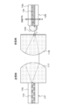
- FIG. 1 shows an outline of optical communication by spatial coupling.
- the light emitted from the optical fiber 10T on the transmitting side is formed into collimated light by the lens 11T and emitted.
- this collimated light is condensed by the lens 11R on the receiving side and incident on the optical fiber 10R.
- the optical fibers 10T and 10R have a double structure consisting of a core 10a at the center of the optical path and a clad 10b covering the periphery thereof.
- FIG. 2A shows the basic structure of an optical fiber.
- An optical fiber has a structure in which a central portion called a core is covered with a layer called a clad.
- the refractive index n1 of the core is high
- the refractive index n2 of the cladding is low
- the light is confined in the core and propagates.
- FIG. 2B shows the LPml (Linearly Polarized) mode of the step-type optical fiber, in which the normalized propagation constant b is shown as a function of the normalized frequency V.
- the horizontal axis is the normalized frequency V, which can be expressed by the following mathematical formula (1).
- d is the core diameter
- NA is the numerical aperture
- ⁇ is the wavelength of light.
- V ⁇ dNA / ⁇ ⁇ ⁇ ⁇ (1)
- LP01 is a basic mode (0th-order mode), and thereafter LP11, LP21, ... Are the primary mode, the secondary mode, ..., Respectively.
- V 1.92.
- FIGS. 4 and 5 show an example of factors that deteriorate the accuracy of optical axis alignment.
- the optical axis shift occurs due to the non-uniform amount of the fixing materials 16T and 16R for fixing the ferrules 15T and 15R and the optical fibers 10T and 10R.
- the optical axis shift occurs due to insufficient shaping accuracy of the lenses 11T and 11R.
- the optical axis shift occurs due to insufficient accuracy of the positioning mechanism (recessed portion 17T, convex portion 17R) provided in the ferrules 15T and 15R.
- the convex portion 17R shown in FIGS. 5A and 5B may be a pin.
- an optical fiber is assumed to be capable of propagating only the basic mode at the first wavelength, and the optical fiber uses light of a second wavelength capable of propagating at least the primary mode together with the basic mode. Is configured to communicate.
- the normalized frequency V 2.96 as shown in FIG. 6 (b). Therefore, as shown in FIG. 6A, the basic mode of LP01 and the primary mode of LP11 can exist.
- the position of the optical fiber on the receiving side is displaced in the direction perpendicular to the optical axis under the condition that only the basic mode of LP01 exists in the input light. (Refer to the arrows in FIGS. 7A and 7B), that is, consider the case where the optical axis shift occurs.
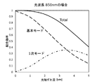
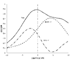
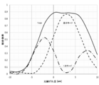
- FIG. 8 is a graph showing the simulation results of the coupling efficiency of optical power in that case.
- the horizontal axis represents the amount of optical axis deviation, and the vertical axis represents the coupling efficiency.
- the coupling efficiency becomes 1. Then, for example, when only 50% of the power is propagated into the optical fiber with respect to the input light, the coupling efficiency is 0.5.
- the basic mode (0th-order mode) component and the 1st-order mode component are described separately, and the sum of them forms a total curve. Since the input light has only the basic mode, it can be seen that the basic mode is converted to the primary mode according to the deviation. On the other hand, in the case of 1310 nm, since only the basic mode can propagate as shown in FIG. 3 (a), the basic mode is purely reduced as shown in FIG.
- the positions are about 1.8 times when compared at a bonding efficiency of 0.8 (about -1 dB) and about 2.35 times when compared at a bonding efficiency of 0.9 (about ⁇ 0.5 dB).
- the accuracy against deviation can be relaxed.
- the optical fiber can propagate only the basic mode at the first wavelength (for example, 1310 nm), and the light of the second wavelength (for example, 850 nm) that the optical fiber can propagate at least in the primary mode together with the basic mode. It is possible to increase the coupling efficiency of the optical power by configuring the communication using the above.
- the present technology is configured to perform communication using light having at least a primary mode component together with the basic mode.
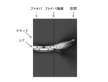
- FIG. 11 is a diagram simulating the intensity distribution of light transmitted in the optical fiber.
- FIG. 11A shows an example in which light having only the components of the basic mode is transmitted. In this case, the center of the core of the optical fiber has the highest strength, and the closer to the clad, the lower the strength.
- FIG. 11B shows an example of transmitting light having components of the basic mode and the primary mode. In this case, the high-strength portions appear alternately in one direction and the other direction with respect to the center of the core, and in the upward and downward directions in the illustrated example.
- FIG. 13A the light emitted from the center of the core 10a on the transmitting side is coupled to the center of the core 10a on the receiving side.
- FIG. 13B in the case of transmitting light having the components of the basic mode and the primary mode, the light whose intensity distribution is biased upward from the center of the core 10a on the transmitting side is received. It is connected downward with respect to the center of the core 10a on the side.
- the state shown in the figure is a state in which the amount of optical axis deviation is zero.
- the optical axis shift is in the positive (+) direction
- the portion having high light intensity is in the direction of entering the core 10a of the optical fiber 10R, so that it is easy to combine.
- the optical axis shift is in the negative ( ⁇ ) direction
- the core 10a of the optical fiber 10R moves in the direction opposite to the traveling direction of the light, so that the coupling efficiency is lowered.
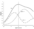
- FIG. 15 shows a simulation result of the coupling efficiency of optical power when the input light (light emitted from the transmitting side) has the components of the basic mode and the primary mode and the ratio is 1: 1. It is a graph.
- the horizontal axis represents the amount of optical axis deviation, and the vertical axis represents the coupling efficiency.
- the basic mode (0th-order mode) and the 1st-order mode are described separately, and the sum of them forms a total curve.
- the coupling efficiency drops significantly when the deviation is in the negative (-) direction, but thanks to the conversion of the basic mode to the primary mode component, the coupling efficiency is 0 with a deviation amount of -1.5 ⁇ m. It is about 7.
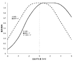
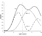
- FIG. 17 is a graph showing simulation results of optical power coupling efficiency when the input light has only the basic mode component and when the input light has the basic mode and primary mode components.
- the horizontal axis represents the amount of optical axis deviation, and the vertical axis represents the coupling efficiency.
- the bonding efficiency at the location where the strength is maximized is standardized as 1.
- the coupling efficiency is better than when the input light has only the components of the basic mode. This is because, as described above, when the optical axis deviation is in the positive (+) direction, the portion having high light intensity is in the direction of entering the core 10a of the optical fiber 10R, so that it is easy to combine.
- the coupling efficiency is worse when the optical axis shift is in the negative (-) direction than when the input light has only the components of the basic mode. .. This is because the core 10a of the optical fiber 10R moves in the direction opposite to the traveling direction of the light as described above.
- the coupling efficiency of the optical power with respect to the optical axis deviation in the negative (-) direction is configured to include an optical path adjusting unit that adjusts the optical path so as to guide the input light to the core of the optical waveguide.
- FIG. 18 shows an example in which a lens (convex lens) 12R as an optical path adjusting portion is provided on the incident side of the optical fiber 10R.
- a lens convex lens
- FIG. 18 shows an example in which a lens (convex lens) 12R as an optical path adjusting portion is provided on the incident side of the optical fiber 10R.
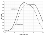
- FIG. 19 is a graph showing simulation results of optical power coupling efficiency in the case of a double lens (DoubleLens) provided with a lens 12R and in the case of a single lens (SingleLens) not provided with a lens 12R.
- the horizontal axis represents the amount of optical axis deviation
- the vertical axis represents the coupling efficiency. With respect to the optical axis shift in the negative (-) direction, the coupling efficiency of the double lens is higher than that of the single lens.
- the basic mode (0th-order mode) component and the 1st-order mode component are described separately, and the sum of them forms a total curve. ..
- the reason why the coupling efficiency of the double lens is higher than that of the single lens with respect to the optical axis deviation in the negative (-) direction is as follows. That is, even if the optical fiber 10R is displaced in the negative (-) direction by returning the light in the optical axis direction, the light is directed toward the center of the fiber, which has the effect of reducing the loss in the basic mode as compared with the single lens. This is due to the effect of increasing the rate at which the basic mode is converted to the primary mode. Comparing the case of the coupling efficiency of 0.7, it is ⁇ 1.5 ⁇ m for the single lens and -4 ⁇ m for the double lens, and it can be seen that the accuracy can be relaxed 2.7 times. Therefore, the accuracy of the double lens can be relaxed and the cost of parts can be reduced.
- FIG. 21 is an example in which the optical path adjusting member 13R is provided on the incident side of the optical fiber 10R.
- the optical path adjusting member 13R includes a central portion 13R_1 having a tapered surface 13a whose diameter gradually narrows toward the core 10a of the optical fiber 10R, and an outer peripheral portion 13R_2 around the central portion 13R_1.
- the central portion 13R_1 is composed of the same member as the core 10a of the optical fiber 10R
- the outer peripheral portion 13R_2 is composed of the same member as the clad 10b of the optical fiber 10R.
- the optical path adjusting member 13R By providing the optical path adjusting member 13R on the incident side of the optical fiber 10R in this way, light that deviates downward with respect to the optical axis can be reflected by the tapered surface 13a toward the optical axis side and returned to the center direction of the optical axis. it can. As a result, as in the case of the double lens described above, the coupling efficiency of the optical power can be increased with respect to the optical axis deviation in the negative ( ⁇ ) direction.
- FIG. 22 is a graph showing simulation results of optical power coupling efficiency in the case where the optical path adjusting member 13R is provided and in the case of a single lens (Single Lens) in which the optical path adjusting member 13R is not provided.
- the horizontal axis represents the amount of optical axis deviation
- the vertical axis represents the coupling efficiency.
- the optical path adjusting member 13R is provided for the optical axis deviation in the negative ( ⁇ ) direction
- the coupling efficiency is higher than that of the single lens.
- the basic mode (0th mode) component and the primary mode component are described separately, and the sum of them is the total. It becomes a curve of.
- FIG. 24 shows a case where the input light has only the basic mode component and the optical path adjusting member 13R is not provided (dashed line), and a case where the input light has only the basic mode component and the optical path adjusting member 13R is provided (broken line).
- the horizontal axis represents the amount of optical axis deviation, and the vertical axis represents the coupling efficiency.
- the bonding efficiency at the location where the strength is maximized is standardized as 1.
- the coupling efficiency is better when the optical path adjusting member 13R is provided than when the optical path adjusting member 13R is not provided. This is because the light deviating from the core 10a has a function of returning to the core 10a by the tapered surface 13a.
- the optical path adjusting member 13R When the optical path adjusting member 13R is provided and the input light has only the components of the basic mode or the components of the basic mode and the primary mode, the basic mode and the components of the primary mode are compared.
- the coupling efficiency is better with respect to the axial deviation in the positive (+) direction than when having only the mode component. This is because, when the light is deviated in the positive (+) direction, the portion having high light intensity is likely to be incident on the core 10a side of the optical fiber 10R.
- the size of the mouth on the incident end side of the tapered surface 13a is larger than the size of the core 10a, so that light traveling in a direction deviating from the core 10a It can be seen that the tapered surface 13a picks up the input light to the same extent as in the basic mode.
- FIG. 25 is an example in which the optical path adjusting member 14R is provided between the core 10a and the clad 10b at the incident end of the optical fiber 10R.
- the optical path adjusting member 14R has a tapered surface 14a whose diameter gradually narrows toward the core 10a as a surface in contact with the clad 10b, and a cylindrical surface 14b as a surface in contact with the core 10a.
- the cylindrical surface 14b has the same refractive index as the core 10a
- the tapered surface 14a has the same refractive index as the clad 10b
- the light path adjusting member 14R By providing the optical path adjusting member 14R between the core 10a and the clad 10b at the incident end of the optical fiber 10R in this way, the light path adjusting member 14R having the tapered surface 14a allows the light deviating downward with respect to the optical axis. It can be reflected to the optical axis side and returned to the center direction of the optical axis, and as in the case of the above-mentioned double lens, the coupling efficiency of optical power can be increased against the optical axis deviation in the negative (-) direction. ..
- FIG. 26 is a graph showing simulation results of optical power coupling efficiency in the case where the optical path adjusting member 14R is provided and in the case of a single lens (Single Lens) in which the optical path adjusting member 14R is not provided.
- the horizontal axis represents the amount of optical axis deviation
- the vertical axis represents the coupling efficiency.
- the optical path adjusting member 14R is provided for the optical axis deviation in the negative ( ⁇ ) direction
- the coupling efficiency is higher than that of the single lens.
- the basic mode (0th mode) component and the primary mode component are described separately, and the sum of them is the total. It becomes a curve of.
- the configuration of the optical path adjusting member 13R provided at the incident end of the optical fiber 10R of FIG. 21 may be the same as that of the incident end of the optical fiber 10R of FIG. It is conceivable that the configuration of the incident end of the fiber 10R is the same as that of the optical path adjusting member 13R provided at the incident end of the optical fiber 10R of FIG.
- FIG. 28 is an example in which the optical path adjusting member 21R is provided between the core 10a and the clad 10b at the incident end of the optical fiber 10R.
- the optical path adjusting member 21R has a tapered surface 21a whose diameter gradually expands from the core 10a as a surface in contact with the clad 10b, and a cylindrical surface 21b as a surface in contact with the core 10a.
- the cylindrical surface 21b has the same refractive index as the core 10a
- the tapered surface 21a has the same refractive index as the clad 10b
- the optical path adjusting member 21R between the core 10a at the incident end of the optical fiber 10R and the clad 10b in this way, even if the optical axis is deviated downward or upward, the light is tapered via the clad 10b. It can enter the portion and be further coupled to the core 10a. As a result, as in the case of the double lens described above, the coupling efficiency of the optical power can be increased with respect to the optical axis deviation in the negative ( ⁇ ) direction.
- FIG. 29 is a graph showing simulation results of optical power coupling efficiency in the case where the optical path adjusting member 21R is provided and in the case of a single lens (Single Lens) in which the optical path adjusting member 21R is not provided.
- the horizontal axis represents the amount of optical axis deviation
- the vertical axis represents the coupling efficiency.
- the optical path adjusting member 21R is provided for the optical axis deviation in the negative ( ⁇ ) direction
- the coupling efficiency is higher than that of the single lens.
- the basic mode (0th mode) component and the primary mode component are described separately, and the sum of them is the total. It becomes a curve of.
- the configuration of the optical path adjusting member 13R provided at the incident end of the optical fiber 10R of FIG. 21 is the same as that of the incident end of the optical fiber 10R of FIG. 28.
- FIG. 31 is an example in which the optical path adjusting member 22R is provided on the incident side of the optical fiber 10R.
- the optical path adjusting member 22R is a member having a refractive index distribution.
- the refractive index of the optical path adjusting member 22R has a refractive index equivalent to that of the core 10a of the optical fiber 10R on the optical axis, and has a gradation structure in which the refractive index decreases as the distance from the optical axis increases in the vertical direction.
- the optical path adjusting member 22R By providing the optical path adjusting member 22R on the incident side of the optical fiber 10R in this way, the light entering the optical path adjusting member 22R travels while bending in the optical axis direction due to the gradation effect. Further, even if the optical axis is deviated, the light can be returned toward the center. The reason is that when the optical path shifts downward with respect to the optical axis as shown by the broken line in FIG. 32, the light near the optical axis bends less because the difference in refractive index is small, and the light deviates from the optical axis. This is because the amount of bending is large because the difference in refractive index is large, and therefore the light is collected near the center of the core 10a. As a result, as in the case of the double lens described above, it is possible to increase the coupling efficiency of the optical power with respect to the optical axis deviation in the negative ( ⁇ ) direction.
- FIG. 33 is a graph showing simulation results of optical power coupling efficiency in the case where the optical path adjusting member 22R is provided and in the case of a single lens (Single Lens) in which the optical path adjusting member 22R is not provided.
- the horizontal axis represents the amount of optical axis deviation
- the vertical axis represents the coupling efficiency.
- the optical path adjusting member 22R is provided for the optical axis deviation in the negative ( ⁇ ) direction
- the coupling efficiency is higher than that of the single lens.
- the basic mode (0th mode) component and the primary mode component are described separately, and the sum of them is the total. It becomes a curve of.
- FIG. 35 is an example in which the optical path adjusting member 19R is provided on the incident side of the optical fiber 10R.
- the optical path adjusting member 19R is a member having a funnel-shaped space 19b having a tapered surface 19a whose diameter gradually narrows toward the core 10a of the optical fiber 10R.
- a mirror is arranged on the tapered surface 19a in order to totally reflect the input light. Regarding this mirror, it is conceivable not only to fix the separately generated mirror to the tapered surface 19a, but also to form the mirror on the tapered surface 19a by thin film deposition or the like.
- the optical path adjusting member 19R By providing the optical path adjusting member 19R on the incident side of the optical fiber 10R in this way, light that deviates downward with respect to the optical axis can be reflected by the tapered surface 19a toward the optical axis side and returned to the center direction of the optical axis. it can. As a result, as in the case of the double lens described above, the coupling efficiency of the optical power can be increased with respect to the optical axis deviation in the negative ( ⁇ ) direction.
- the funnel-shaped space 19b has a bottom portion, but it is conceivable that the bottom portion is eliminated to form a through hole.
- FIG. 36 shows a transmission / reception system 100 as an embodiment.
- the transmission / reception system 100 includes a transmitter 200, a receiver 300, and a cable 400.
- the transmitter 200 is, for example, an AV source such as a personal computer, a game machine, a disc player, a set-top box, a digital camera, or a mobile phone.
- the receiver 300 is, for example, a television receiver, a projector, or the like.
- the transmitter 200 and the receiver 300 are connected via a cable 400.
- the transmitter 200 has a light emitting unit 201, a connector 202 as a receptacle, and an optical fiber 203 that propagates the light emitted by the light emitting unit 201 to the connector 202.
- the light emitting unit 201 includes a laser element such as a VCSEL (Vertical Cavity Surface Emitting LASER) or a light emitting element such as an LED (light emission diode).
- the light emitting unit 201 converts an electric signal (transmission signal) generated by a transmission circuit (not shown) into an optical signal.
- the optical signal emitted by the light emitting unit 201 is propagated to the connector 202 through the optical fiber 203.
- the receiver 300 has a connector 301 as a receptacle, a light receiving unit 302, and an optical fiber 303 that propagates the light obtained by the connector 301 to the light receiving unit 302.
- the light receiving unit 302 includes a light receiving element such as a photodiode.
- the light receiving unit 302 converts an optical signal sent from the connector 301 into an electric signal (received signal) and supplies it to a receiving circuit (not shown).
- the cable 400 is configured to have connectors 402 and 403 as plugs at one end and the other end of the optical fiber 401.
- the connector 402 at one end of the optical fiber 401 is connected to the connector 202 of the transmitter 200, and the connector 403 at the other end of the optical fiber 401 is connected to the connector 301 of the receiver 300.
- the optical fiber 203 of the transmitter 200, the optical fiber 303 of the receiver 300, and the optical fiber 401 of the cable 400 propagate only in the basic mode at the first wavelength. Further, these optical fibers are configured so that the wavelength dispersion becomes zero at the first wavelength.
- the first wavelength is 1310 nm
- these optical fibers function as single-mode fibers at a wavelength of 1310 nm (see FIG. 3).
- communication is performed using light having a second wavelength and at least a primary mode component together with the basic mode.
- the second wavelength is a wavelength at which each of the above-mentioned optical fibers can propagate at least the primary mode together with the basic mode.
- the second wavelength is 850 nm.
- the 850 nm light (having the components of the basic mode and the primary mode) emitted by the light emitting unit 201 is propagated to the connector 202 by the optical fiber 203 which is a 1310 nm single mode fiber.
- the portion of the connector 402 is provided with an optical path adjusting unit that adjusts the optical path so as to guide the input light to the core of the optical fiber 401.
- the optical path adjusting unit includes, for example, the lens 12R shown in FIG. 18, the optical path adjusting member 13R shown in FIG. 21, the optical path adjusting member 14R shown in FIG. 25, the optical path adjusting member 21R shown in FIG. 28, and the optical path adjusting member 22R shown in FIG. , The optical path adjusting member 19R shown in FIG. 35 and the like.
- the 850 nm light (having the components of the basic mode and the primary mode) emitted from the connector 202 is coupled to the core of the optical fiber 401, which is a 1310 nm single mode fiber, and propagates to the receiver 300 side through the optical path adjustment unit. Will be done.
- the input light that does not go from the connector 202 to the core of the optical fiber 401 of the connector 402 is optical path adjusted by the optical path adjusting unit and guided to the core of the optical fiber 401, and at this time, light having a wavelength of 850 nm is used. Since the incident angle that can be transmitted by the optical fiber 401 is wider than when light having a wavelength of 1310 nm is used, the coupling loss of optical power can be reduced. Further, in this case, when there is an optical axis shift of the light incident on the optical fiber 401, the primary mode generated by the optical axis shift is propagated together with the basic mode, so that the coupling loss of the optical power is reduced. It is possible to reduce the accuracy of misalignment and reduce costs.
- the connector 301 is provided with an optical path adjusting unit that adjusts the optical path so as to guide the input light to the core of the optical fiber 303. Then, the 850 nm light (having the components of the basic mode and the primary mode) emitted from the connector 403 is coupled to the core of the optical fiber 303, which is a 1310 nm single mode fiber, to the light receiving unit 302 through the optical path adjusting unit. Propagate.
- FIG. 37 is a perspective view showing a configuration example of the connector 202 of the transmitter 200 and the connector 402 of the cable 400.
- FIG. 38 is also a perspective view showing a configuration example of the connector 202 of the transmitter 200 and the connector 402 of the cable 400, but is a view seen from the direction opposite to that of FIG. 37.
- the illustrated example corresponds to the parallel transmission of optical signals of a plurality of channels, but although detailed description thereof will be omitted, the example corresponding to the transmission of optical signals of one channel can be similarly configured.
- the optical path adjusting portion provided in the portion of the connector 402 is a lens (see FIG. 18) will be described.
- the connector 202 includes a connector body (ferrule) 211 having a substantially rectangular parallelepiped appearance.
- a plurality of optical fibers 203 corresponding to each channel are connected to the back side of the connector main body 211 in a horizontally arranged state. The tip side of each optical fiber 203 is inserted into the optical fiber insertion hole 216 and fixed.
- an adhesive injection hole 212 having a rectangular opening is formed on the upper surface side of the connector main body 211. An adhesive for fixing the optical fiber 203 to the connector main body 211 is injected from the adhesive injection hole 212.
- a concave light emitting portion (light transmission space) 213 having a rectangular opening is formed on the front side of the connector main body 211, and the bottom portion of the light emitting portion 213 corresponds to each channel.
- a plurality of lenses (convex lenses) 214 are formed in a state of being arranged in the horizontal direction. As a result, the surface of the lens 214 is prevented from being inadvertently hit by the connector or the like on the other side and being damaged.
- a convex or concave position restricting portion 215 for aligning with the connector 402, or concave in the illustrated example, is integrally formed. As a result, the optical axis alignment at the time of connection with the connector 402 can be easily performed.
- the connector 402 includes a connector body 411 having a substantially rectangular parallelepiped appearance.
- the connector main body 411 is configured by connecting a first optical unit 412 and a second optical unit (ferrule) 413. Since the connector main body 411 is composed of the first optical unit 412 and the second optical unit 413 in this way, although not shown in FIGS. 37 and 38, a second lens as an optical path adjusting unit ( Convex lenses) can be easily manufactured.
- a concave light incident portion (light transmission space) 415 having a rectangular opening is formed on the front surface side of the first optical portion 412, and the bottom portion of the light incident portion 415 corresponds to each channel.
- a plurality of first lenses (convex lenses) 416 are formed in a state of being arranged in the horizontal direction. As a result, the surface of the first lens 416 is prevented from being inadvertently hit by the connector or the like on the other side and being damaged.
- a convex or concave position restricting portion 417 for aligning with the connector 202, or a convex position regulating portion 417 in the illustrated example is integrally formed.
- the position regulating unit 417 is not limited to the one integrally formed with the first optical unit 412, and a pin may be used or another method may be used. ..
- a plurality of optical fibers 401 corresponding to each channel are connected to the back side of the second optical unit 413 in a horizontally arranged state.
- the tip side of each optical fiber 401 is inserted into the optical fiber insertion hole 418 and fixed.
- an adhesive injection hole 414 having a rectangular opening is formed on the upper surface side of the second optical unit 413. An adhesive for fixing the optical fiber 401 to the second optical unit 413 is injected from the adhesive injection hole 414.
- FIG. 39A is a cross-sectional view showing an example of the connector 202 of the transmitter 200.
- the position regulating unit 215 (see FIG. 37) is not shown.
- the connector 202 will be further described with reference to FIG. 39 (a).
- the connector 202 includes a connector main body 211.
- the connector main body 211 is made of a light-transmitting material such as synthetic resin or glass, or a material such as silicon that transmits a specific wavelength, and has a ferrule with a lens.
- the connector body 211 By configuring the connector body 211 as a ferrule with a lens in this way, it is possible to easily align the optical axis between the optical fiber and the lens. Further, since the connector main body 211 is configured as a ferrule with a lens in this way, even in the case of multiple channels, multi-channel communication can be easily realized simply by inserting the optical fiber into the ferrule.
- the connector main body 211 is formed with a concave light emitting portion (light transmission space) 213 on the front side thereof. Then, the connector main body 211 is integrally formed with lenses (convex lenses) 214 corresponding to each channel arranged in the horizontal direction so as to be located at the bottom portion of the light emitting portion 213. As a result, the positional accuracy of the lens 214 with respect to the core 203a of the optical fiber 203 installed in the connector main body 211 can be improved at the same time in a plurality of channels.
- the connector main body 211 is provided with a plurality of optical fiber insertion holes 216 extending forward from the back side in a state of being arranged in the horizontal direction in accordance with the lens 214 of each channel.
- the optical fiber 203 has a double structure consisting of a core 203a in a central portion serving as an optical path and a clad 203b covering the periphery thereof.
- the optical fiber insertion holes 216 of each channel are formed so that the optical axes of the lens 214 corresponding to the core 203a of the optical fiber 203 inserted therein coincide with each other. Further, the optical fiber insertion holes 216 of each channel are formed so that the bottom position thereof, that is, the contact position of the tip (incident end) of the optical fiber 203 when inserted, matches the focal position of the lens 214. ing.
- the connector main body 211 is formed so that adhesive injection holes 212 extending downward from the upper surface side communicate with each other near the bottom positions of a plurality of optical fiber insertion holes 216 arranged in the horizontal direction. .. After the optical fiber 203 is inserted into the optical fiber insertion hole 216, the adhesive 217 is injected around the optical fiber 203 from the adhesive injection hole 212, so that the optical fiber 203 is fixed to the connector main body 211.
- the lens 214 has a function of molding the light emitted from the optical fiber 203 into collimated light and emitting the light. As a result, the light emitted from the exit end of the optical fiber 203 is incident on the lens 214, formed into collimated light, and emitted.
- FIG. 39B is a cross-sectional view showing an example of the connector 402 of the cable 400.
- the position regulating unit 417 (see FIGS. 37 and 38) is not shown.
- the connector 402 will be further described with reference to FIG. 39 (b).
- the connector 402 includes a connector main body 411 configured by connecting the first optical unit 412 and the second optical unit 413.
- the first optical unit 412 is made of a light-transmitting material such as synthetic resin or glass, or a material such as silicon that transmits a specific wavelength.
- a concave light incident portion (light transmission space) 415 is formed on the front surface side of the first optical portion 412.
- the first lens 416 corresponding to each channel is integrally formed on the first optical unit 412 in a state of being arranged in the horizontal direction so as to be located at the bottom portion of the light incident portion 415. There is. As a result, the positional accuracy of the first lens 416 with respect to the first optical unit 412 can be improved.
- a concave space 420 is formed on the back side of the first optical unit 412. This space 420 is sealed on the front side of the second optical unit 413 to form a closed space.
- the second lens 421 of each channel formed on the front surface side of the second optical unit 413 is in a state of being located in this enclosed space.
- the second optical unit 413 is made of a light-transmitting material such as synthetic resin or glass, or a material such as silicon that transmits a specific wavelength, and is configured as a ferrule with a lens. As described above, the second optical unit 413 is connected to the first optical unit 412 to form the connector main body 411.
- the material of the second optical unit 413 is the same as that of the material of the first optical unit 412 because the optical path shift due to distortion in the two optical units when the heat changes can be suppressed by aligning the coefficients of thermal expansion. It is preferably present, but it may be a different material.
- the second optical unit 413 is configured as a ferrule with a lens in this way, the optical axis of the optical fiber 401 and the second lens 421 can be easily aligned. Further, since the second optical unit 413 is configured as a ferrule with a lens in this way, even in the case of multiple channels, multi-channel communication can be easily realized simply by inserting the optical fiber 401 into the ferrule.
- the second optical unit 413 is integrally formed with the second lens 421 corresponding to each channel arranged in the horizontal direction on the front surface side thereof. As a result, the positional accuracy of the second lens 421 with respect to the core 401a of the optical fiber 401 installed in the second optical unit 413 can be improved at the same time in a plurality of channels.
- the second optical unit 413 is provided with a plurality of optical fiber insertion holes 418 extending forward from the back side in a state of being arranged in the horizontal direction in accordance with the second lens 421 of each channel.
- the optical fiber 401 has a double structure consisting of a core 401a at the center of the optical path and a clad 401b covering the periphery thereof.
- the optical fiber insertion hole 418 of each channel is formed so that the core 401a of the optical fiber 401 inserted therein and the optical axis of the corresponding second lens 421 coincide with each other. Further, the optical fiber insertion hole 418 of each channel has its bottom position, that is, when the optical fiber 401 is inserted, the contact position of the tip (incident end) of the optical fiber insertion hole 418 matches the focal position of the second lens 421. , Molded.
- adhesive injection holes 414 extending downward from the upper surface side are formed so as to communicate with each other near the bottom positions of a plurality of optical fiber insertion holes 418 arranged in the horizontal direction. Has been done. After the optical fiber 401 is inserted into the optical fiber insertion hole 418, the adhesive 419 is injected around the optical fiber 401 from the adhesive injection hole 414, whereby the optical fiber 401 is fixed to the second optical unit 413. To.
- the first optical unit 412 and the second optical unit 413 are connected to form the connector main body 411.
- this connection method a method of newly providing a concave portion on one side and a convex portion on the other side such as a boss to fit the lens, or a method of aligning the optical axis positions of the lenses with each other and fixing them by adhesion using an image processing system or the like is adopted. obtain.
- the first lens 416 has a function of collecting the incident collimated light.
- the second lens 421 has a function of adjusting the optical path so as to guide the incident light to the core 401a of the optical fiber 401 (see FIG. 18).
- the collimated light is incident on the first lens 416 and condensed, and the condensed light is incident on the incident end of the optical fiber 401 through the second lens 421.
- FIG. 40 shows a cross-sectional view of a state in which the connector 202 of the transmitter 200 and the connector 402 of the cable 400 are connected.
- the light transmitted through the optical fiber 203 is emitted from the exit end of the optical fiber 203 with a predetermined NA.
- the emitted light is incident on the lens 214, formed into collimated light, and emitted toward the connector 402.
- the light emitted from the connector 202 is incident on the first lens 416 and condensed. Then, the collected light is incident on the incident end of the optical fiber 401 through the second lens 421 and sent through the optical fiber 401.
- the connector 403 of the cable 400 and the connector 301 of the receiver 300 in FIG. 36 are configured in the same manner as the configuration example of the connector 202 of the transmitter 200 and the connector 402 of the cable 400 described above.
- the first wavelength is set to 1310 nm, but since a laser light source or an LED light source can be used as the light source, the first wavelength is, for example, between 300 nm and 5 ⁇ m. It is possible that there is.
- the first wavelength has been described as 1310 nm, but it is also conceivable that the first wavelength is a wavelength in the 1310 nm band including 1310 nm. Further, in the above-described embodiment, the first wavelength has been described as 1310 nm, but it is also conceivable that the first wavelength is a wavelength in the 1550 nm band including 1550 nm or 1550 nm. Further, although the second wavelength has been described as 850 nm, it is also conceivable that the second wavelength is a wavelength in the 850 nm band including 850 nm.
- the optical waveguide is an optical fiber
- this technique can be applied to an optical waveguide other than the optical fiber, such as a silicon optical waveguide.
- the present technology may have the following configurations.
- An optical waveguide that propagates only the basic mode at the first wavelength is provided. Communicate using light having a second wavelength and at least a primary mode component together with the basic mode.
- the second wavelength is an optical communication device in which the optical waveguide can propagate at least the primary mode together with the basic mode.
- the optical communication device according to (1) above further comprising an optical path adjusting unit that adjusts an optical path so as to guide input light to the core of the optical waveguide.
- the optical path adjusting unit adjusts an optical path by utilizing refraction by a lens.
- optical path adjusting unit adjusts the optical path by utilizing reflection by an optical path adjusting member having a tapered surface whose aperture gradually narrows toward the incident side of the optical waveguide.
- Communication device (5)
- the optical path adjusting portion is provided between the core and the clad at the incident end of the optical waveguide, and the surface in contact with the clad gradually expands from the same diameter as the core and from the core to the above.
- the optical communication device wherein the optical path is adjusted by using an optical path adjusting member whose refractive index gradually changes from the same refractive index as that of the core toward the clad to the same refractive index as that of the clad.
- the optical path adjusting unit is provided on the incident side of the optical waveguide, has a refractive index equivalent to that of the core of the optical waveguide on the optical axis, and has a gradient structure in which the refractive index decreases as the distance from the optical axis increases in the vertical direction.
- the first wavelength is a wavelength at which the wavelength dispersion becomes zero.
- the optical communication device (9) The optical communication device according to (8) above, wherein the first wavelength is a wavelength in the 1310 nm band or the 1550 nm band. (10) The optical communication device according to any one of (1) to (9) above, wherein the second wavelength is a wavelength in the 850 nm band. (11) The optical communication device according to any one of (1) to (10) above, wherein the optical waveguide is an optical fiber. (12) The optical communication device according to any one of (1) to (10) above, wherein the optical waveguide is a silicon optical waveguide. (13) In an optical communication device provided with an optical waveguide that propagates only in the basic mode at the first wavelength, communication is performed using light having a second wavelength and at least a primary mode component together with the basic mode.
- the second wavelength is an optical communication method in which the optical waveguide can propagate at least the primary mode together with the basic mode.
- the second wavelength is an optical communication system in which the optical waveguide can propagate at least the primary mode together with the basic mode.
- the transmitter is a receptacle of a transmitter or a plug of a cable.
Abstract
The present invention can ease precision with respect to displacement and thus reduce costs. Communication is carried out using light having a second wavelength and having a component with a fundamental mode and at least a primary mode. Here, the second wavelength is a wavelength at which an optical waveguide can propagate the fundamental mode together with at least the primary mode. For example, the present invention is provided with a light path adjusting unit that adjusts a light path so that input light is guided towards the core of the optical waveguide.
Description
本技術は、光通信装置、光通信方法および光通信システムに関する。詳しくは、位置ずれの精度を緩和可能な光通信装置等に関する。
This technology relates to optical communication devices, optical communication methods, and optical communication systems. More specifically, the present invention relates to an optical communication device or the like capable of alleviating the accuracy of misalignment.
従来、空間結合による光通信(例えば、特許文献1参照)が知られている。この光通信の場合、特に、シングルモードファイバにおいては、位置ずれにより光パワーの大きなロスが発生する。そのため、従来は、位置ずれを抑えるために部品の精度要求が高く、コストアップにつながっている。
Conventionally, optical communication by spatial coupling (see, for example, Patent Document 1) is known. In the case of this optical communication, especially in a single mode fiber, a large loss of optical power occurs due to misalignment. Therefore, conventionally, the accuracy requirement of the parts is high in order to suppress the misalignment, which leads to an increase in cost.
本技術の目的は、位置ずれの精度を緩和してコスト削減を図ることにある。
The purpose of this technology is to reduce the accuracy of misalignment and reduce costs.
本技術の概念は、
第1の波長では基本モードのみを伝搬する光導波路を備え、
第2の波長を持つと共に上記基本モードと共に少なくとも1次モードの成分を持つ光を用いて通信をし、
上記第2の波長は、上記光導波路が上記基本モードと共に少なくとも1次モードを伝搬し得る波長である
光通信装置にある。 The concept of this technology is
The first wavelength has an optical waveguide that propagates only in basic mode.
Communicate using light having a second wavelength and at least a primary mode component together with the basic mode.
The second wavelength is in an optical communication device, which is a wavelength at which the optical waveguide can propagate at least the primary mode together with the basic mode.
本技術においては、第1の波長では基本モードのみを伝搬する光導波路を備えるものである。例えば、光導波路は、光ファイバあるいはシリコン光導波路である、ようにされてもよい。また、例えば、第1の波長は、波長分散がゼロとなる波長である、ようにされてもよい。また、例えば、第1の波長は、300nmから5μmの間にある、ようにされてもよい。また、例えば、第1の波長は、1310nm帯または1550nm帯の波長である、ようにされてもよい。
In this technology, an optical waveguide that propagates only the basic mode at the first wavelength is provided. For example, the optical waveguide may be an optical fiber or a silicon optical waveguide. Further, for example, the first wavelength may be a wavelength at which the wavelength dispersion becomes zero. Also, for example, the first wavelength may be set to be between 300 nm and 5 μm. Further, for example, the first wavelength may be a wavelength in the 1310 nm band or the 1550 nm band.
そして、本技術においては、第2の波長を持つと共に基本モードと共に少なくとも1次モードの成分を持つ光を用いて通信をするものである。ここで、第2の波長は、光導波路が基本モードと共に少なくとも1次モードを伝搬し得る波長である。この場合、第2の波長は、第1の波長より短い。例えば、第2の波長は、850nm帯の波長である、ようにされてもよい。
Then, in the present technology, communication is performed using light having a second wavelength and at least a primary mode component together with the basic mode. Here, the second wavelength is a wavelength at which the optical waveguide can propagate at least the primary mode together with the basic mode. In this case, the second wavelength is shorter than the first wavelength. For example, the second wavelength may be a wavelength in the 850 nm band.
このように本技術においては、第1の波長では基本モードのみを伝搬する光導波路を備えるものであって、その光導波路が基本モードと共に少なくとも1次モードを伝搬し得る第2の波長を持つと共に基本モードと共に少なくとも1次モードの成分を持つ光を用いて通信をするものである。
As described above, in the present technology, an optical waveguide that propagates only the basic mode at the first wavelength is provided, and the optical waveguide has a second wavelength that can propagate at least the primary mode together with the basic mode. Communication is performed using light having at least a primary mode component together with the basic mode.
そのため、第2の波長の光を用いて通信を行うものであり、光軸ずれによって発生する少なくとも1次モードの成分が基本モードの成分と共に光導波路を伝搬していくので、光軸ずれによる光パワーの結合ロスを低減することが可能となる。また、この場合、基本モードと共に少なくとも1次モードの成分を持つ光を用いて通信を行うものであり、光導波路に入射される光の光軸ずれに対して、そのずれの方向によっては、第2の波長を用いるが基本モードの成分からなる光を用いて通信を行う場合に比べて光パワーの結合効率を高めることが可能となる。
Therefore, communication is performed using light of the second wavelength, and at least the component of the primary mode generated by the optical axis shift propagates along the optical waveguide together with the component of the basic mode, so that the light due to the optical axis shift is transmitted. It is possible to reduce the power coupling loss. Further, in this case, communication is performed using light having at least a primary mode component together with the basic mode, and the optical axis shift of the light incident on the optical waveguide depends on the direction of the shift. Although two wavelengths are used, it is possible to increase the coupling efficiency of optical power as compared with the case where communication is performed using light composed of components of the basic mode.
なお、本技術において、例えば、入力光を光導波路のコアに導くように光路を調整する光路調整部をさらに備える、ようにされてもよい。この場合、例えば、光路調整部は、レンズによる屈折を利用して光路を調整する、ようにされてもよい。また、この場合、例えば、光路調整部は、光導波路の入射側に向かって口径が徐々に狭まっていくテーパー面を持つ光路調整部材による反射を利用して光路を調整する、ようにされてもよい。また、この場合、例えば、光路調整部は、光導波路の入射端のコアとクラッドとの間に設けられ、クラッドに接する面がコアと同じ口径から徐々に口径が広がっていくと共にコアからクラッドに向かって屈折率がコアと同じ屈折率からクラッドと同じ屈折率に順次変化していく光路調整部材を利用して光路を調整する、ようにされてもよい。また、この場合、例えば、光路調整部は、光導波路の入射側に設けられ、光軸上では光導波路のコアと同等の屈折率を持ち、光軸から垂直方向に離れるほど屈折率が下がるグラデーション構造の屈折率を持つ光路調整部材を利用して光路を調整する、ようにされてもよい。
In the present technology, for example, an optical path adjusting unit that adjusts the optical path so as to guide the input light to the core of the optical waveguide may be further provided. In this case, for example, the optical path adjusting unit may adjust the optical path by utilizing the refraction by the lens. Further, in this case, for example, the optical path adjusting unit may adjust the optical path by utilizing the reflection by the optical path adjusting member having a tapered surface whose aperture gradually narrows toward the incident side of the optical waveguide. Good. Further, in this case, for example, the optical path adjusting portion is provided between the core and the clad at the incident end of the optical waveguide, and the surface in contact with the clad gradually expands from the same diameter as the core and gradually expands from the core to the clad. The optical path may be adjusted by using an optical path adjusting member whose refractive index gradually changes from the same refractive index as that of the core to the same refractive index as that of the clad. Further, in this case, for example, the optical path adjusting portion is provided on the incident side of the optical waveguide, has a refractive index equivalent to that of the core of the optical waveguide on the optical axis, and the refractive index decreases as the distance from the optical axis increases in the vertical direction. The optical path may be adjusted by using an optical path adjusting member having a refractive index of the structure.
このように入力光が光路調整されて光導波路のコアに導くようにされることで、基本モードと共に少なくとも1次モードの成分を持つ光を用いて通信を行うことで発生する光パワーの結合ロスを低減することが可能となる。
By adjusting the optical path of the input light and guiding it to the core of the optical waveguide in this way, the coupling loss of optical power generated by communicating using light having at least the primary mode component together with the basic mode. Can be reduced.
また、本技術の他の概念は、
第1の波長では基本モードのみを伝搬する光導波路を持つ受信部と、
上記受信部の上記光導波路に、第2の波長を持つと共に上記基本モードと共に少なくとも1次モードの成分を持つ光を入射する送信部を備え、
上記第2の波長は、上記光導波路が上記基本モードと共に少なくとも1次モードを伝搬し得る波長である
光通信システムにある。 In addition, other concepts of this technology
A receiver with an optical waveguide that propagates only the basic mode at the first wavelength,
The optical waveguide of the receiving unit is provided with a transmitting unit that injects light having a second wavelength and having at least a primary mode component together with the basic mode.
The second wavelength is in an optical communication system, which is a wavelength at which the optical waveguide can propagate at least the primary mode together with the basic mode.
本技術においては、受信部と送信部を備えるものである。受信部は、第1の波長では基本モードのみを伝搬する光導波路を持っている。送信部から、受信部の光導波路に、第2の波長を持つと共に基本モードと共に少なくとも1次モードの成分を持つ光が入射される。ここで、第2の波長は、光導波路が基本モードと共に少なくとも1次モードを伝搬し得る波長である。例えば、送信部は、送信機のレセプタクル、またはケーブルのプラグである、ようにされてもよい。
This technology includes a receiving unit and a transmitting unit. The receiver has an optical waveguide that propagates only the basic mode at the first wavelength. Light having a second wavelength and having at least a primary mode component as well as a basic mode is incident on the optical waveguide of the receiving unit from the transmitting unit. Here, the second wavelength is a wavelength at which the optical waveguide can propagate at least the primary mode together with the basic mode. For example, the transmitter may be a receptacle of the transmitter, or a plug of a cable.
このように本技術においては、受信部が第1の波長では基本モードのみを伝搬する光導波路を持つものであって、送信部からその光導波路に、その光導波路が基本モードと共に少なくとも1次モードを伝搬し得る第2の波長を持つと共に基本モードと共に少なくとも1次モードの成分を持つ光が入射されるものである。そのため、光軸ずれによる光パワーの結合ロスを低減することが可能となる。
As described above, in the present technology, the receiving unit has an optical waveguide that propagates only the basic mode at the first wavelength, and the optical waveguide is transmitted from the transmitting unit to the optical waveguide in at least the primary mode together with the basic mode. Light having a second wavelength capable of propagating the light and having a component of at least the primary mode together with the basic mode is incident. Therefore, it is possible to reduce the coupling loss of optical power due to the deviation of the optical axis.
以下、発明を実施するための形態(以下、「実施の形態」とする)について説明する。なお、説明は以下の順序で行う。
1.実施の形態
2.変形例 Hereinafter, embodiments for carrying out the invention (hereinafter referred to as “embodiments”) will be described. The description will be given in the following order.
1. 1.Embodiment 2. Modification example
1.実施の形態
2.変形例 Hereinafter, embodiments for carrying out the invention (hereinafter referred to as “embodiments”) will be described. The description will be given in the following order.
1. 1.
<1.実施の形態>
[本技術に関する基本説明]
まず、本技術に関する技術について説明をする。図1は、空間結合による光通信の概要を示している。この場合、送信側の光ファイバ10Tから出射された光はレンズ11Tでコリメート光に成形されて出射される。そして、このコリメート光が受信側のレンズ11Rで集光されて光ファイバ10Rに入射される。この光通信の場合、特に、シングルモードファイバにおいては、位置ずれにより光パワーの大きなロスが発生する。なお、光ファイバ10T,10Rは、光路となる中心部のコア10aと、その周囲を覆うクラッド10bの二重構造となっている。 <1. Embodiment>
[Basic explanation of this technology]
First, the technology related to this technology will be described. FIG. 1 shows an outline of optical communication by spatial coupling. In this case, the light emitted from theoptical fiber 10T on the transmitting side is formed into collimated light by the lens 11T and emitted. Then, this collimated light is condensed by the lens 11R on the receiving side and incident on the optical fiber 10R. In the case of this optical communication, especially in a single mode fiber, a large loss of optical power occurs due to misalignment. The optical fibers 10T and 10R have a double structure consisting of a core 10a at the center of the optical path and a clad 10b covering the periphery thereof.
[本技術に関する基本説明]
まず、本技術に関する技術について説明をする。図1は、空間結合による光通信の概要を示している。この場合、送信側の光ファイバ10Tから出射された光はレンズ11Tでコリメート光に成形されて出射される。そして、このコリメート光が受信側のレンズ11Rで集光されて光ファイバ10Rに入射される。この光通信の場合、特に、シングルモードファイバにおいては、位置ずれにより光パワーの大きなロスが発生する。なお、光ファイバ10T,10Rは、光路となる中心部のコア10aと、その周囲を覆うクラッド10bの二重構造となっている。 <1. Embodiment>
[Basic explanation of this technology]
First, the technology related to this technology will be described. FIG. 1 shows an outline of optical communication by spatial coupling. In this case, the light emitted from the
次に、モードの基本的な考え方について説明する。光ファイバ内をシングルモードで伝搬しようとする場合、モードが1つだけ存在するように、ファイバの屈折率やコア径といったパラメータを決める必要がある。
Next, the basic concept of the mode will be explained. When attempting to propagate in an optical fiber in a single mode, it is necessary to determine parameters such as the refractive index and core diameter of the fiber so that there is only one mode.
図2(a)は、光ファイバの基本的な構造を示している。光ファイバは、コアと呼ばれる中心部をクラッドと呼ばれる層で覆った構造となっている。この場合、コアの屈折率n1は高く、クラッドの屈折率n2は低くされており、光はコアの中に閉じ込められて伝搬していく。
FIG. 2A shows the basic structure of an optical fiber. An optical fiber has a structure in which a central portion called a core is covered with a layer called a clad. In this case, the refractive index n1 of the core is high, the refractive index n2 of the cladding is low, and the light is confined in the core and propagates.
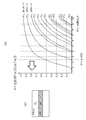
図2(b)は、ステップ型光ファイバのLPml (Linearly Polarized:直線偏光) モードであり、規格化伝搬定数bを規格化周波数Vの関数として示したものである。縦軸は規格化伝搬定数bであり、あるモードが通らない(遮断)状態ではb=0となり、光パワーがコア内に閉じ込められるほど(伝搬できるほど)、bは1に近づく。横軸は規格化周波数Vで、以下の数式(1)で表すことができる。ここで、dはコア径、NAは開口数、λは光の波長である。
V=πdNA/λ ・・・(1) FIG. 2B shows the LPml (Linearly Polarized) mode of the step-type optical fiber, in which the normalized propagation constant b is shown as a function of the normalized frequency V. The vertical axis is the normalized propagation constant b, and b = 0 in a state where a certain mode does not pass (blocking), and b approaches 1 as the optical power is confined in the core (propagation is possible). The horizontal axis is the normalized frequency V, which can be expressed by the following mathematical formula (1). Here, d is the core diameter, NA is the numerical aperture, and λ is the wavelength of light.
V = πdNA / λ ・ ・ ・ (1)
例えば、V=2.405のときLP11が遮断される状態となるため、モードはLP01のみ存在することになる。従って、V=2.405以下の状態がシングルモードとなる。ここで、LP01は基本モード(0次モード)であり、以降LP11, LP21,・・・が、それぞれ、1次モード、2次モード、・・・となる。
For example, when V = 2.405, LP11 is cut off, so only LP01 exists as a mode. Therefore, the single mode is in the state of V = 2.405 or less. Here, LP01 is a basic mode (0th-order mode), and thereafter LP11, LP21, ... Are the primary mode, the secondary mode, ..., Respectively.
例えば、図3(a)のように、シングルモードで一般的な1310nmのケースで規格化周波数Vを考えてみる。ここで、コア径d、開口数NAをそれぞれ1310nm光ファイバの一般的なパラメータであるd=8μm、NA=0.1とし、ファイバを伝搬する光の波長を1310nmとすると、数式(1)からV=1.92となる。
For example, as shown in FIG. 3A, consider the normalized frequency V in the case of 1310 nm, which is common in single mode. Here, assuming that the core diameter d and the numerical aperture NA are 1310 nm, which are general parameters of an optical fiber, d = 8 μm and NA = 0.1, and the wavelength of light propagating through the fiber is 1310 nm, the equation (1) shows. V = 1.92.
従って、図3(b)に示すように、規格化周波数Vは2.405以下となるため、LP01の基本モードのみ伝搬されることとなり、シングルモードとなる。ここで、コア径を大きくすると伝播できるモードが増えることになる。因みに、例えば、一般的なマルチモードファイバはコア径を50μmといった値にすることで数百のモードを伝搬させている。
Therefore, as shown in FIG. 3B, since the normalized frequency V is 2.405 or less, only the basic mode of LP01 is propagated, and the single mode is adopted. Here, increasing the core diameter will increase the modes that can be propagated. Incidentally, for example, a general multimode fiber propagates hundreds of modes by setting the core diameter to a value such as 50 μm.
図1に示すような空間結合による光通信を考えた場合、シングルモードでは、コア径が小さいため、送信側/受信側の光結合部の位置合わせがシビアになり、正確に光軸を合わせるための精度要求が高くなるという問題がある。
When considering optical communication by spatial coupling as shown in FIG. 1, in single mode, since the core diameter is small, the alignment of the optical coupling portion on the transmitting side / receiving side becomes severe, and the optical axis is accurately aligned. There is a problem that the accuracy requirement of is high.
この問題を解決するために、一般的に、高精度な部品を使用したり、光ファイバへの光入力部を加工することで光をファイバコアへ挿入し易くしたりする。しかし、高精度な部品はコストが高く、また加工を要するものは加工費が高くなるため、シングルモード通信用のコネクタやシステムは一般的にコストが高くなる。
In order to solve this problem, generally, high-precision parts are used, or light is easily inserted into the fiber core by processing the optical input part to the optical fiber. However, high-precision parts are expensive, and those that require processing are expensive, so connectors and systems for single-mode communication are generally expensive.
図4、図5は、光軸合わせの精度劣化要因の一例を示している。例えば、図4(a)に示すように、フェルール15T,15Rと光ファイバ10T,10Rを固定するための固定材16T,16Rの量の不均一により、光軸ずれが発生する。また、例えば、図4(b)に示すように、レンズ11T,11Rの整形精度不足により、光軸ずれが発生する。
FIGS. 4 and 5 show an example of factors that deteriorate the accuracy of optical axis alignment. For example, as shown in FIG. 4A, the optical axis shift occurs due to the non-uniform amount of the fixing materials 16T and 16R for fixing the ferrules 15T and 15R and the optical fibers 10T and 10R. Further, for example, as shown in FIG. 4B, the optical axis shift occurs due to insufficient shaping accuracy of the lenses 11T and 11R.
また、図5(a),(b)に示すように、フェルール15T,15Rに設けた位置合わせ用機構(凹部17T、凸部17R)の精度不足により、光軸ずれが発生する。なお、図5(a),(b)に示す凸部17Rは、ピンであることもある。
Further, as shown in FIGS. 5A and 5B, the optical axis shift occurs due to insufficient accuracy of the positioning mechanism (recessed portion 17T, convex portion 17R) provided in the ferrules 15T and 15R. The convex portion 17R shown in FIGS. 5A and 5B may be a pin.
本技術は、光軸合わせの精度を緩和してコスト削減を可能とするものである。本技術では、第1に、光ファイバは第1の波長では基本モードのみを伝搬し得るものとされ、この光ファイバが基本モードと共に少なくとも1次モードを伝搬し得る第2の波長の光を用いて通信を行うように構成される。
This technology makes it possible to reduce costs by relaxing the accuracy of optical axis alignment. In the present technology, first, an optical fiber is assumed to be capable of propagating only the basic mode at the first wavelength, and the optical fiber uses light of a second wavelength capable of propagating at least the primary mode together with the basic mode. Is configured to communicate.
例えば、図3(a)と同じ条件の光ファイバに、1310nmではなく、850nmの波長の光を入力した場合、図6(b)に示すように、規格化周波数V=2.96となる。そのため、図6(a)に示すように、LP01の基本モードと、LP11の1次モードが存在し得ることになる。
For example, when light having a wavelength of 850 nm instead of 1310 nm is input to the optical fiber under the same conditions as in FIG. 3 (a), the normalized frequency V = 2.96 as shown in FIG. 6 (b). Therefore, as shown in FIG. 6A, the basic mode of LP01 and the primary mode of LP11 can exist.
図7(a)に示すような光学系を組んだ際に、入力光にはLP01の基本モードしか存在しない条件で、受信側の光ファイバの位置が光軸に対して垂直方向にずれた場合(図7(a),(b)の矢印参照)、つまり光軸ずれが発生した場合について考える。
When the optical system as shown in FIG. 7A is assembled, the position of the optical fiber on the receiving side is displaced in the direction perpendicular to the optical axis under the condition that only the basic mode of LP01 exists in the input light. (Refer to the arrows in FIGS. 7A and 7B), that is, consider the case where the optical axis shift occurs.
図8は、その場合における光パワーの結合効率のシミュレーション結果を記載したグラフである。横軸は光軸ずれ量で、縦軸は結合効率を表している。ずれがない状態では、光ファイバ内へ100%のパワーが伝搬し、結合効率は1となる。そして、例えば、入力光に対して光ファイバ内へ50%しかパワーが伝搬されない場合は、結合効率は0.5となる。
FIG. 8 is a graph showing the simulation results of the coupling efficiency of optical power in that case. The horizontal axis represents the amount of optical axis deviation, and the vertical axis represents the coupling efficiency. When there is no deviation, 100% of the power propagates into the optical fiber, and the coupling efficiency becomes 1. Then, for example, when only 50% of the power is propagated into the optical fiber with respect to the input light, the coupling efficiency is 0.5.
入力光の波長を1310nmと850nmで比較すると、850nmの場合の特性が良いことが分かる。この理由は、1310nmの場合には基本モードのみしか伝搬できないのに対して、850nmの場合、基本モードの他に1次モードも伝搬できるためである(図6(a)参照)。
Comparing the wavelengths of the input light between 1310 nm and 850 nm, it can be seen that the characteristics at 850 nm are good. The reason for this is that in the case of 1310 nm, only the basic mode can be propagated, whereas in the case of 850 nm, the primary mode can be propagated in addition to the basic mode (see FIG. 6A).
つまり、光軸ずれがない状態では、図9(a)に示すように、入力光には基本モードしか存在しない。一方、光軸ずれがある状態では、図9(b)に示すように、基本モードの一部がクラッドとコアの屈折率差で生じる位相差を利用して1次モードへ変換される。1310nmの場合はこの1次モードを伝搬できないが、850nmの場合はこの1次モードも伝搬できることから、850nmの場合の特性が良くなる。
That is, in the state where there is no optical axis deviation, as shown in FIG. 9A, there is only a basic mode for the input light. On the other hand, in a state where there is an optical axis shift, as shown in FIG. 9B, a part of the basic mode is converted to the primary mode by utilizing the phase difference generated by the difference in refractive index between the clad and the core. In the case of 1310 nm, this primary mode cannot be propagated, but in the case of 850 nm, this primary mode can also be propagated, so that the characteristics in the case of 850 nm are improved.
図10のグラフには、基本モード(0次モード)成分と1次モード成分を分離して記載しており、足し合わせたものがトータル(Total)の曲線となる。入力光は基本モードしか存在しないため、ずれに応じて基本モードが1次モードへ変換されていることが分かる。一方、1310nmの場合、図3(a)に示すように基本モードしか伝搬できないため、図8に示すように、基本モードが純粋に減少している。
In the graph of FIG. 10, the basic mode (0th-order mode) component and the 1st-order mode component are described separately, and the sum of them forms a total curve. Since the input light has only the basic mode, it can be seen that the basic mode is converted to the primary mode according to the deviation. On the other hand, in the case of 1310 nm, since only the basic mode can propagate as shown in FIG. 3 (a), the basic mode is purely reduced as shown in FIG.
図8において、1310nmと850nmについて、結合効率0.8(約-1dB)で比較すると約1.8倍、結合効率0.9(約―0.5dB)で比較すると約2.35倍も位置ずれに対する精度を緩和することができる。
In FIG. 8, for 1310 nm and 850 nm, the positions are about 1.8 times when compared at a bonding efficiency of 0.8 (about -1 dB) and about 2.35 times when compared at a bonding efficiency of 0.9 (about −0.5 dB). The accuracy against deviation can be relaxed.
このように光ファイバを第1の波長(例えば1310nm)では基本モードのみを伝搬し得るものとし、この光ファイバが基本モードと共に少なくとも1次モードを伝搬し得る第2の波長(例えば850nm)の光を用いて通信を行うように構成することで、光パワーの結合効率を高めることが可能となる。
Thus, it is assumed that the optical fiber can propagate only the basic mode at the first wavelength (for example, 1310 nm), and the light of the second wavelength (for example, 850 nm) that the optical fiber can propagate at least in the primary mode together with the basic mode. It is possible to increase the coupling efficiency of the optical power by configuring the communication using the above.
また、本技術では、第2に、基本モードと共に少なくとも1次モードの成分を持つ光を用いて通信を行うように構成される。
Secondly, the present technology is configured to perform communication using light having at least a primary mode component together with the basic mode.
図11は、光ファイバ内を伝達する光の強度分布をシミュレーションした図である。図11(a)は、基本モードの成分のみを持つ光を伝送する場合の例を示している。この場合、光ファイバのコアの中心が最も強度が高く、クラッドへ近づくほど強度が低くなる。図11(b)は、基本モードおよび1次モードの成分を持つ光を伝送する場合の例を示している。この場合、強度の高い箇所がコアの中心に対して一方向および他方向に、図示の例では上方向および下方向に交互に現れる。
FIG. 11 is a diagram simulating the intensity distribution of light transmitted in the optical fiber. FIG. 11A shows an example in which light having only the components of the basic mode is transmitted. In this case, the center of the core of the optical fiber has the highest strength, and the closer to the clad, the lower the strength. FIG. 11B shows an example of transmitting light having components of the basic mode and the primary mode. In this case, the high-strength portions appear alternately in one direction and the other direction with respect to the center of the core, and in the upward and downward directions in the illustrated example.
図11(b)の状態にあるとき、図12に示すようにファイバ端面から光が出射される際に、その光は、コアの中心に対して強度の高い方にある角度を持って進むものとなる。
In the state shown in FIG. 11B, when light is emitted from the fiber end face as shown in FIG. 12, the light travels at an angle higher in intensity with respect to the center of the core. It becomes.
図1に示すような空間結合による光通信を考える。図13(a)のように、送信側のコア10aの中心から出た光は受信側のコア10aの中心へと結合する。しかし、図13(b)のように、基本モードおよび1次モードの成分を持つ光を伝送する場合であって、送信側のコア10aの中心から上方向側へ強度分布が偏った光は受信側のコア10aの中心に対して下方向側へ結合する。
Consider optical communication by spatial coupling as shown in Fig. 1. As shown in FIG. 13A, the light emitted from the center of the core 10a on the transmitting side is coupled to the center of the core 10a on the receiving side. However, as shown in FIG. 13B, in the case of transmitting light having the components of the basic mode and the primary mode, the light whose intensity distribution is biased upward from the center of the core 10a on the transmitting side is received. It is connected downward with respect to the center of the core 10a on the side.
図13(b)のような条件で、図14に示すように、受信側の光ファイバ10Rの位置がレンズ11Rに対して垂直方向にずれる光軸ずれが発生した場合について考える。この場合、図示の状態が光軸ずれ量がゼロの状態である。光軸ずれが正(+)方向である場合は、光の強度の高い箇所は光ファイバ10Rのコア10aに入り込む方向のため結合し易くなる。一方、光軸ずれが負(-)方向である場合は、光の進行方向とは逆側に光ファイバ10Rのコア10aが移動することになるため結合効率が下がる。
Consider a case where the position of the optical fiber 10R on the receiving side is displaced in the direction perpendicular to the lens 11R, as shown in FIG. 14, under the conditions as shown in FIG. 13B. In this case, the state shown in the figure is a state in which the amount of optical axis deviation is zero. When the optical axis shift is in the positive (+) direction, the portion having high light intensity is in the direction of entering the core 10a of the optical fiber 10R, so that it is easy to combine. On the other hand, when the optical axis shift is in the negative (−) direction, the core 10a of the optical fiber 10R moves in the direction opposite to the traveling direction of the light, so that the coupling efficiency is lowered.
図15は、入力光(送信側から出射される光)が基本モードおよび1次モードの成分を持っており、その割合が1対1である場合における光パワーの結合効率のシミュレーション結果を記載したグラフである。横軸は光軸ずれ量で、縦軸は結合効率を表している。図示の例では、基本モード(0次モード)と1次モードを分離して記載しており、足し合わせたものがトータル(Total)の曲線となる。基本モードのみだと負(-)方向でずれた場合に結合効率が著しく下がっているが、基本モードが1次モード成分へ変換されるおかげで、-1.5μmのずれ量で結合効率0.7程度となっている。
FIG. 15 shows a simulation result of the coupling efficiency of optical power when the input light (light emitted from the transmitting side) has the components of the basic mode and the primary mode and the ratio is 1: 1. It is a graph. The horizontal axis represents the amount of optical axis deviation, and the vertical axis represents the coupling efficiency. In the illustrated example, the basic mode (0th-order mode) and the 1st-order mode are described separately, and the sum of them forms a total curve. In the basic mode only, the coupling efficiency drops significantly when the deviation is in the negative (-) direction, but thanks to the conversion of the basic mode to the primary mode component, the coupling efficiency is 0 with a deviation amount of -1.5 μm. It is about 7.
ここで、図13に示すような空間結合による光通信において、入力光(送信側から出射される光)に含まれる成分が基本モードのみの場合と、基本モードおよび1次モードが混在する場合について、図16に示すように、受信側の光ファイバ10Rの位置がレンズ11Rに対して垂直方向にずれる光軸ずれが発生した場合について考える。
Here, in the case of optical communication by spatial coupling as shown in FIG. 13, the case where the component contained in the input light (light emitted from the transmitting side) is only the basic mode and the case where the basic mode and the primary mode are mixed. As shown in FIG. 16, consider a case where the position of the optical fiber 10R on the receiving side shifts in the direction perpendicular to the lens 11R and an optical axis shift occurs.
図17は、入力光が基本モードの成分のみを持つ場合と、入力光が基本モードおよび1次モードの成分を持つ場合における光パワーの結合効率のシミュレーション結果を記載したグラフである。横軸は光軸ずれ量で、縦軸は結合効率を表している。ここでは、基準を揃えるために、強度が最大となる箇所の結合効率を1として規格化している。
FIG. 17 is a graph showing simulation results of optical power coupling efficiency when the input light has only the basic mode component and when the input light has the basic mode and primary mode components. The horizontal axis represents the amount of optical axis deviation, and the vertical axis represents the coupling efficiency. Here, in order to align the standards, the bonding efficiency at the location where the strength is maximized is standardized as 1.
入力光が基本モードおよび1次モードの成分を持つ場合、光軸ずれが正(+)方向であるときは、入力光が基本モードの成分のみを持つ場合よりも、結合効率はよくなる。これは、上述したように、光軸ずれが正(+)方向である場合は光の強度の高い箇所が光ファイバ10Rのコア10aに入り込む方向のため結合し易くなるからである。
When the input light has the components of the basic mode and the primary mode, when the optical axis shift is in the positive (+) direction, the coupling efficiency is better than when the input light has only the components of the basic mode. This is because, as described above, when the optical axis deviation is in the positive (+) direction, the portion having high light intensity is in the direction of entering the core 10a of the optical fiber 10R, so that it is easy to combine.
しかし、入力光が基本モードおよび1次モードの成分を持つ場合、光軸ずれが負(-)方向である場合は、入力光が基本モードの成分のみを持つ場合よりも、結合効率は悪化する。これは、上述したように光の進行方向とは逆側に光ファイバ10Rのコア10aが移動するためである。
However, when the input light has the components of the basic mode and the primary mode, the coupling efficiency is worse when the optical axis shift is in the negative (-) direction than when the input light has only the components of the basic mode. .. This is because the core 10a of the optical fiber 10R moves in the direction opposite to the traveling direction of the light as described above.
このように基本モードと共に少なくとも1次モードの成分を持つ光を用いて通信を行うように構成することで、光軸ずれに対して、そのずれの方向によっては、基本モードの成分からなる光を用いて通信を行う場合に比べて、光パワーの結合効率を高めることが可能となる。この場合、入力光の進行方向と同方向へのみ光ファイバの軸ずれが許容できるように設計することで、基本モードの成分のみを持つ入力光よりも基本モードおよび1次モードの成分を持つ入力光の方が軸ずれに対して強くなる。
By configuring communication using light having at least a primary mode component together with the basic mode in this way, light composed of the basic mode component can be generated with respect to the optical axis deviation depending on the direction of the deviation. It is possible to increase the coupling efficiency of optical power as compared with the case of performing communication by using it. In this case, by designing so that the axial deviation of the optical fiber can be tolerated only in the same direction as the traveling direction of the input light, the input having the basic mode and primary mode components is more than the input light having only the basic mode components. Light is more resistant to misalignment.
また、本技術では、第3に、基本モードと共に少なくとも1次モードの成分を持つ光を用いて通信を行う場合にあって、負(-)方向の光軸ずれに対して光パワーの結合効率を高めるために、入力光を光導波路のコアに導くように光路を調整する光路調整部を備えるように構成される。
Further, in the present technology, thirdly, in the case of communicating using light having at least a primary mode component together with the basic mode, the coupling efficiency of the optical power with respect to the optical axis deviation in the negative (-) direction. It is configured to include an optical path adjusting unit that adjusts the optical path so as to guide the input light to the core of the optical waveguide.
図18は、光ファイバ10Rの入射側に、光路調整部としてのレンズ(凸レンズ)12Rを設けた例を示している。このようにレンズ12Rを設けることで、光軸に対して下方向へ外れる光をレンズ効果で光軸の中心方向へ戻すことができる。これにより、負(-)方向の光軸ずれに対し光パワーの結合効率を上げることができる。
FIG. 18 shows an example in which a lens (convex lens) 12R as an optical path adjusting portion is provided on the incident side of the optical fiber 10R. By providing the lens 12R in this way, light that deviates downward with respect to the optical axis can be returned to the center direction of the optical axis by the lens effect. As a result, the coupling efficiency of optical power can be increased with respect to the optical axis deviation in the negative (−) direction.
図19は、レンズ12Rを設けたダブルレンズ(Double Lens)の場合と、レンズ12Rを設けないシングルレンズ(Single Lens)の場合における光パワーの結合効率のシミュレーション結果を記載したグラフである。横軸は光軸ずれ量で、縦軸は結合効率を表している。負(-)方向の光軸ずれに対してダブルレンズの場合はシングルレンズの場合より結合効率が上がっている。なお、図20のグラフには、ダブルレンズの場合において、基本モード(0次モード)成分と1次モード成分を分離して記載しており、足し合わせたものがトータル(Total)の曲線となる。
FIG. 19 is a graph showing simulation results of optical power coupling efficiency in the case of a double lens (DoubleLens) provided with a lens 12R and in the case of a single lens (SingleLens) not provided with a lens 12R. The horizontal axis represents the amount of optical axis deviation, and the vertical axis represents the coupling efficiency. With respect to the optical axis shift in the negative (-) direction, the coupling efficiency of the double lens is higher than that of the single lens. In the graph of FIG. 20, in the case of a double lens, the basic mode (0th-order mode) component and the 1st-order mode component are described separately, and the sum of them forms a total curve. ..
このように負(-)方向の光軸ずれに対してダブルレンズの場合はシングルレンズの場合より結合効率が上がるのは、以下の効果によるものと考えられる。すなわち、光軸方向へ光を戻すことにより光ファイバ10Rが負(-)方向へずれた場合でも光はファイバの中心方向へ向かうため、シングルレンズよりも基本モードのそもそものロスを減らせる効果と、基本モードが1次モードへ変換される割合を上げることができる効果によるものである。結合効率0.7の場合で比べると、シングルレンズでは-1.5μmであるのに対して、ダブルレンズでは-4μmであり、2.7倍の精度緩和が可能であることが分かる。よってダブルレンズの方が精度緩和可能であり、部品のコストも削減できる。
It is considered that the reason why the coupling efficiency of the double lens is higher than that of the single lens with respect to the optical axis deviation in the negative (-) direction is as follows. That is, even if the optical fiber 10R is displaced in the negative (-) direction by returning the light in the optical axis direction, the light is directed toward the center of the fiber, which has the effect of reducing the loss in the basic mode as compared with the single lens. This is due to the effect of increasing the rate at which the basic mode is converted to the primary mode. Comparing the case of the coupling efficiency of 0.7, it is −1.5 μm for the single lens and -4 μm for the double lens, and it can be seen that the accuracy can be relaxed 2.7 times. Therefore, the accuracy of the double lens can be relaxed and the cost of parts can be reduced.
図21は、光ファイバ10Rの入射側に光路調整部材13Rを設けた例である。この光路調整部材13Rは、光ファイバ10Rのコア10aに向かって口径が徐々に狭まっていくテーパー面13aを持つ中心部13R_1と、その周りの外周部13R_2からなっている。中心部13R_1は光ファイバ10Rのコア10aと同じ部材で構成され、外周部13R_2は光ファイバ10Rのクラッド10bと同じ部材で構成される。なお、ここでは同じ部材で構成されるとしたが、必ずしも同じ部材である必要はなく、同様の機能を果たす別部材で構成することも考えられる。
FIG. 21 is an example in which the optical path adjusting member 13R is provided on the incident side of the optical fiber 10R. The optical path adjusting member 13R includes a central portion 13R_1 having a tapered surface 13a whose diameter gradually narrows toward the core 10a of the optical fiber 10R, and an outer peripheral portion 13R_2 around the central portion 13R_1. The central portion 13R_1 is composed of the same member as the core 10a of the optical fiber 10R, and the outer peripheral portion 13R_2 is composed of the same member as the clad 10b of the optical fiber 10R. Although it is assumed that the members are the same here, the members do not necessarily have to be the same, and it is conceivable that the members are different members having the same functions.
このように光ファイバ10Rの入射側に光路調整部材13Rを設けることで、光軸に対して下方向へ外れる光をテーパー面13aで光軸側へ反射させて光軸の中心方向へ戻すことができる。これにより、上述のダブルレンズの場合と同様に、負(-)方向の光軸ずれに対し光パワーの結合効率を上げることができる。
By providing the optical path adjusting member 13R on the incident side of the optical fiber 10R in this way, light that deviates downward with respect to the optical axis can be reflected by the tapered surface 13a toward the optical axis side and returned to the center direction of the optical axis. it can. As a result, as in the case of the double lens described above, the coupling efficiency of the optical power can be increased with respect to the optical axis deviation in the negative (−) direction.
図22は、光路調整部材13Rを設けた場合と、光路調整部材13Rを設けないシングルレンズ(Single Lens)の場合における光パワーの結合効率のシミュレーション結果を記載したグラフである。横軸は光軸ずれ量で、縦軸は結合効率を表している。負(-)方向の光軸ずれに対して光路調整部材13Rを設けた場合はシングルレンズの場合より結合効率が上がっている。なお、図23のグラフには、光路調整部材13Rを設けた場合において、基本モード(0次モード)成分と1次モード成分を分離して記載しており、足し合わせたものがトータル(Total)の曲線となる。
FIG. 22 is a graph showing simulation results of optical power coupling efficiency in the case where the optical path adjusting member 13R is provided and in the case of a single lens (Single Lens) in which the optical path adjusting member 13R is not provided. The horizontal axis represents the amount of optical axis deviation, and the vertical axis represents the coupling efficiency. When the optical path adjusting member 13R is provided for the optical axis deviation in the negative (−) direction, the coupling efficiency is higher than that of the single lens. In the graph of FIG. 23, when the optical path adjusting member 13R is provided, the basic mode (0th mode) component and the primary mode component are described separately, and the sum of them is the total. It becomes a curve of.
図24は、入力光が基本モードの成分のみを持つと共に光路調整部材13Rを設けない場合(一点鎖線)と、入力光が基本モードの成分のみを持つと共に光路調整部材13Rを設ける場合(破線)と、入力光が基本モードおよび1次モードの成分を持つと共に光路調整部材13Rを設ける場合(実線)における光パワーの結合効率のシミュレーション結果を記載したグラフである。横軸は光軸ずれ量で、縦軸は結合効率を表している。ここでは、基準を揃えるために、強度が最大となる箇所の結合効率を1として規格化している。
FIG. 24 shows a case where the input light has only the basic mode component and the optical path adjusting member 13R is not provided (dashed line), and a case where the input light has only the basic mode component and the optical path adjusting member 13R is provided (broken line). It is a graph which describes the simulation result of the coupling efficiency of the optical power in the case where the input light has the components of the basic mode and the primary mode and the optical path adjusting member 13R is provided (solid line). The horizontal axis represents the amount of optical axis deviation, and the vertical axis represents the coupling efficiency. Here, in order to align the standards, the bonding efficiency at the location where the strength is maximized is standardized as 1.
入力光が基本モードの成分のみを持つ場合で、光路調整部材13Rを設ける、あるいは設けないで比較すると、光路調整部材13Rを設ける場合、光路調整部材13Rを設けない方より、結合効率はよくなる。これは、コア10aから外れる光をテーパー面13aによってコア10aへ戻す働きがあるためである。
Comparing when the input light has only the components of the basic mode and the optical path adjusting member 13R is provided or not provided, the coupling efficiency is better when the optical path adjusting member 13R is provided than when the optical path adjusting member 13R is not provided. This is because the light deviating from the core 10a has a function of returning to the core 10a by the tapered surface 13a.
光路調整部材13Rを設ける場合で、入力光を基本モードの成分のみを持つ場合、あるいは基本モードおよび1次モードの成分を持つ場合で比較すると、基本モードおよび1次モードの成分を持つ場合、基本モードの成分のみを持つ場合より、正(+)方向の軸ずれに対して結合効率はよくなる。これは、正(+)方向にずれた場合、光の強度の高い箇所は光ファイバ10Rのコア10a側へ入射されやすくなるためである。また、負(-)方向の光軸ずれがあった場合でも、テーパー面13aの入射端側の口のサイズがコア10aのサイズよりも大きいため、コア10aから外れる方向に進む光に対してもテーパー面13aにより入力光が基本モードの場合と同程度拾えていることが分かる。
When the optical path adjusting member 13R is provided and the input light has only the components of the basic mode or the components of the basic mode and the primary mode, the basic mode and the components of the primary mode are compared. The coupling efficiency is better with respect to the axial deviation in the positive (+) direction than when having only the mode component. This is because, when the light is deviated in the positive (+) direction, the portion having high light intensity is likely to be incident on the core 10a side of the optical fiber 10R. Further, even if there is an optical axis shift in the negative (-) direction, the size of the mouth on the incident end side of the tapered surface 13a is larger than the size of the core 10a, so that light traveling in a direction deviating from the core 10a It can be seen that the tapered surface 13a picks up the input light to the same extent as in the basic mode.
図25は、光ファイバ10Rの入射端のコア10aとクラッド10bとの間に光路調整部材14Rを設けた例である。この光路調整部材14Rは、クラッド10bに接する面としてコア10aに向かって口径が徐々に狭まっていくテーパー面14aを持つと共に、コア10aと接する面として円筒状の面14bを持っている。この光路調整部材14Rにおいて、円筒状の面14bではコア10aと同屈折率、テーパー面14aではクラッド10bと同屈折率であり、円筒状の面14bからテーパー面14aに向かって屈折率が順次変化していく、いわゆるグラデーション屈折率を持っている。
FIG. 25 is an example in which the optical path adjusting member 14R is provided between the core 10a and the clad 10b at the incident end of the optical fiber 10R. The optical path adjusting member 14R has a tapered surface 14a whose diameter gradually narrows toward the core 10a as a surface in contact with the clad 10b, and a cylindrical surface 14b as a surface in contact with the core 10a. In this optical path adjusting member 14R, the cylindrical surface 14b has the same refractive index as the core 10a, the tapered surface 14a has the same refractive index as the clad 10b, and the refractive index changes sequentially from the cylindrical surface 14b toward the tapered surface 14a. It has a so-called gradient refractive index.
このように光ファイバ10Rの入射端のコア10aとクラッド10bとの間に光路調整部材14Rを設けることで、光軸に対して下方向へ外れる光を、テーパー面14aを持つ光路調整部材14Rで光軸側へ反射させて、光軸の中心方向へ戻すことができ、上述のダブルレンズの場合と同様に、負(-)方向の光軸ずれに対し光パワーの結合効率を上げることができる。
By providing the optical path adjusting member 14R between the core 10a and the clad 10b at the incident end of the optical fiber 10R in this way, the light path adjusting member 14R having the tapered surface 14a allows the light deviating downward with respect to the optical axis. It can be reflected to the optical axis side and returned to the center direction of the optical axis, and as in the case of the above-mentioned double lens, the coupling efficiency of optical power can be increased against the optical axis deviation in the negative (-) direction. ..
図26は、光路調整部材14Rを設けた場合と、光路調整部材14Rを設けないシングルレンズ(Single Lens)の場合における光パワーの結合効率のシミュレーション結果を記載したグラフである。横軸は光軸ずれ量で、縦軸は結合効率を表している。負(-)方向の光軸ずれに対して光路調整部材14Rを設けた場合はシングルレンズの場合より結合効率が上がっている。なお、図27のグラフには、光路調整部材14Rを設けた場合において、基本モード(0次モード)成分と1次モード成分を分離して記載しており、足し合わせたものがトータル(Total)の曲線となる。
FIG. 26 is a graph showing simulation results of optical power coupling efficiency in the case where the optical path adjusting member 14R is provided and in the case of a single lens (Single Lens) in which the optical path adjusting member 14R is not provided. The horizontal axis represents the amount of optical axis deviation, and the vertical axis represents the coupling efficiency. When the optical path adjusting member 14R is provided for the optical axis deviation in the negative (−) direction, the coupling efficiency is higher than that of the single lens. In the graph of FIG. 27, when the optical path adjusting member 14R is provided, the basic mode (0th mode) component and the primary mode component are described separately, and the sum of them is the total. It becomes a curve of.
なお、詳細説明は省略するが、図21の光ファイバ10Rの入射端に設ける光路調整部材13Rの構成を、図25の光ファイバ10Rの入射端と同様の構成にすること、あるいは図25の光ファイバ10Rの入射端の構成を、図21の光ファイバ10Rの入射端に設ける光路調整部材13Rと同様の構成にすることも考えられる。
Although detailed description will be omitted, the configuration of the optical path adjusting member 13R provided at the incident end of the optical fiber 10R of FIG. 21 may be the same as that of the incident end of the optical fiber 10R of FIG. It is conceivable that the configuration of the incident end of the fiber 10R is the same as that of the optical path adjusting member 13R provided at the incident end of the optical fiber 10R of FIG.
図28は、光ファイバ10Rの入射端のコア10aとクラッド10bとの間に光路調整部材21Rを設けた例である。この光路調整部材21Rは、クラッド10bに接する面としてコア10aから口径が徐々に広がっていくテーパー面21aを持つと共に、コア10aと接する面として円筒状の面21bを持っている。この光路調整部材21Rにおいて、円筒状の面21bではコア10aと同屈折率、テーパー面21aではクラッド10bと同屈折率であり、円筒状の面21bからテーパー面21aに向かって屈折率が順次変化していく、いわゆるグラデーション屈折率を持っている。
FIG. 28 is an example in which the optical path adjusting member 21R is provided between the core 10a and the clad 10b at the incident end of the optical fiber 10R. The optical path adjusting member 21R has a tapered surface 21a whose diameter gradually expands from the core 10a as a surface in contact with the clad 10b, and a cylindrical surface 21b as a surface in contact with the core 10a. In this optical path adjusting member 21R, the cylindrical surface 21b has the same refractive index as the core 10a, the tapered surface 21a has the same refractive index as the clad 10b, and the refractive index changes sequentially from the cylindrical surface 21b toward the tapered surface 21a. It has a so-called gradient refractive index.
このように光ファイバ10Rの入射端のコア10aとクラッド10bとの間に光路調整部材21Rを設けることで、光軸が下方向や上方向にずれた場合でも光はクラッド10bを経由してテーパー部分に入り、さらにコア10aに結合させることができる。これにより、上述のダブルレンズの場合と同様に、負(-)方向の光軸ずれに対し光パワーの結合効率を上げることができる。
By providing the optical path adjusting member 21R between the core 10a at the incident end of the optical fiber 10R and the clad 10b in this way, even if the optical axis is deviated downward or upward, the light is tapered via the clad 10b. It can enter the portion and be further coupled to the core 10a. As a result, as in the case of the double lens described above, the coupling efficiency of the optical power can be increased with respect to the optical axis deviation in the negative (−) direction.
図29は、光路調整部材21Rを設けた場合と、光路調整部材21Rを設けないシングルレンズ(Single Lens)の場合における光パワーの結合効率のシミュレーション結果を記載したグラフである。横軸は光軸ずれ量で、縦軸は結合効率を表している。例えば、負(-)方向の光軸ずれに対して光路調整部材21Rを設けた場合はシングルレンズの場合より結合効率が上がっている。なお、図30のグラフには、光路調整部材21Rを設けた場合において、基本モード(0次モード)成分と1次モード成分を分離して記載しており、足し合わせたものがトータル(Total)の曲線となる。
FIG. 29 is a graph showing simulation results of optical power coupling efficiency in the case where the optical path adjusting member 21R is provided and in the case of a single lens (Single Lens) in which the optical path adjusting member 21R is not provided. The horizontal axis represents the amount of optical axis deviation, and the vertical axis represents the coupling efficiency. For example, when the optical path adjusting member 21R is provided for the optical axis deviation in the negative (−) direction, the coupling efficiency is higher than that of the single lens. In the graph of FIG. 30, when the optical path adjusting member 21R is provided, the basic mode (0th mode) component and the primary mode component are described separately, and the sum of them is the total. It becomes a curve of.
なお、詳細説明は省略するが、図21の光ファイバ10Rの入射端に設ける光路調整部材13Rの構成を、図28の光ファイバ10Rの入射端と同様の構成にすることも考えられる。
Although detailed description is omitted, it is conceivable that the configuration of the optical path adjusting member 13R provided at the incident end of the optical fiber 10R of FIG. 21 is the same as that of the incident end of the optical fiber 10R of FIG. 28.
図31は、光ファイバ10Rの入射側に光路調整部材22Rを設けた例である。この光路調整部材22Rは、屈折率分布を持つ部材である。この光路調整部材22Rの屈折率は、光軸上では光ファイバ10Rのコア10aと同等の屈折率を持ち、光軸から垂直方向に離れるほど屈折率が下がるグラデーション構造となっている。
FIG. 31 is an example in which the optical path adjusting member 22R is provided on the incident side of the optical fiber 10R. The optical path adjusting member 22R is a member having a refractive index distribution. The refractive index of the optical path adjusting member 22R has a refractive index equivalent to that of the core 10a of the optical fiber 10R on the optical axis, and has a gradation structure in which the refractive index decreases as the distance from the optical axis increases in the vertical direction.
このように光ファイバ10Rの入射側に光路調整部材22Rを設けることで、光路調整部材22Rに入った光はグラデーション効果により光軸方向へ曲がりながら進む。また、光軸がずれた場合でも光を中心方向へ戻すことができる。その理由は、図32の破線のように光路が光軸に対して下側へずれた場合に、光軸付近の光は屈折率差が少ないため曲がる量は少なく、光軸からより外れた光は屈折率差が大きいため曲がる量が大きく、よって光はコア10aの中心付近に集まるためである。これにより、上述のダブルレンズの場合と同様に、負(-)方向の光軸ずれに対し光パワーの結合効率を上げることができる。
By providing the optical path adjusting member 22R on the incident side of the optical fiber 10R in this way, the light entering the optical path adjusting member 22R travels while bending in the optical axis direction due to the gradation effect. Further, even if the optical axis is deviated, the light can be returned toward the center. The reason is that when the optical path shifts downward with respect to the optical axis as shown by the broken line in FIG. 32, the light near the optical axis bends less because the difference in refractive index is small, and the light deviates from the optical axis. This is because the amount of bending is large because the difference in refractive index is large, and therefore the light is collected near the center of the core 10a. As a result, as in the case of the double lens described above, it is possible to increase the coupling efficiency of the optical power with respect to the optical axis deviation in the negative (−) direction.
図33は、光路調整部材22Rを設けた場合と、光路調整部材22Rを設けないシングルレンズ(Single Lens)の場合における光パワーの結合効率のシミュレーション結果を記載したグラフである。横軸は光軸ずれ量で、縦軸は結合効率を表している。例えば、負(-)方向の光軸ずれに対して光路調整部材22Rを設けた場合はシングルレンズの場合より結合効率が上がっている。なお、図34のグラフには、光路調整部材22Rを設けた場合において、基本モード(0次モード)成分と1次モード成分を分離して記載しており、足し合わせたものがトータル(Total)の曲線となる。
FIG. 33 is a graph showing simulation results of optical power coupling efficiency in the case where the optical path adjusting member 22R is provided and in the case of a single lens (Single Lens) in which the optical path adjusting member 22R is not provided. The horizontal axis represents the amount of optical axis deviation, and the vertical axis represents the coupling efficiency. For example, when the optical path adjusting member 22R is provided for the optical axis deviation in the negative (−) direction, the coupling efficiency is higher than that of the single lens. In the graph of FIG. 34, when the optical path adjusting member 22R is provided, the basic mode (0th mode) component and the primary mode component are described separately, and the sum of them is the total. It becomes a curve of.
図35は、光ファイバ10Rの入射側に光路調整部材19Rを設けた例である。この光路調整部材19Rは、光ファイバ10Rのコア10aに向かって口径が徐々に狭まっていくテーパー面19aを持つ漏斗状空間19bを持つ部材である。テーパー面19aには、入力光を全反射させるために、ミラーが配置されている。このミラーに関しては、別個に生成されたものをテーパー面19aに固定するだけでなく、テーパー面19aに蒸着等で形成することも考えられる。
FIG. 35 is an example in which the optical path adjusting member 19R is provided on the incident side of the optical fiber 10R. The optical path adjusting member 19R is a member having a funnel-shaped space 19b having a tapered surface 19a whose diameter gradually narrows toward the core 10a of the optical fiber 10R. A mirror is arranged on the tapered surface 19a in order to totally reflect the input light. Regarding this mirror, it is conceivable not only to fix the separately generated mirror to the tapered surface 19a, but also to form the mirror on the tapered surface 19a by thin film deposition or the like.
このように光ファイバ10Rの入射側に光路調整部材19Rを設けることで、光軸に対して下方向へ外れる光をテーパー面19aで光軸側へ反射させて光軸の中心方向へ戻すことができる。これにより、上述のダブルレンズの場合と同様に、負(-)方向の光軸ずれに対し光パワーの結合効率を上げることができる。
By providing the optical path adjusting member 19R on the incident side of the optical fiber 10R in this way, light that deviates downward with respect to the optical axis can be reflected by the tapered surface 19a toward the optical axis side and returned to the center direction of the optical axis. it can. As a result, as in the case of the double lens described above, the coupling efficiency of the optical power can be increased with respect to the optical axis deviation in the negative (−) direction.
なお、図35の例では、漏斗状空間19bには底部分が存在するが、この底部分をなくした貫通孔の状態とすることも考えられる。
In the example of FIG. 35, the funnel-shaped space 19b has a bottom portion, but it is conceivable that the bottom portion is eliminated to form a through hole.
[送受信システム]
図36は、実施の形態としての送受信システム100を示している。この送受信システム100は、送信機200と、受信機300と、ケーブル400を有している。送信機200は、例えば、パーソナルコンピュータ、ゲーム機、ディスクプレーヤ、セットトップボックス、デジタルカメラ、携帯電話などのAVソースである。受信機300は、例えば、テレビ受信機、プロジェクタ等である。送信機200と受信機300は、ケーブル400を介して接続されている。 [Transmission / reception system]
FIG. 36 shows a transmission /reception system 100 as an embodiment. The transmission / reception system 100 includes a transmitter 200, a receiver 300, and a cable 400. The transmitter 200 is, for example, an AV source such as a personal computer, a game machine, a disc player, a set-top box, a digital camera, or a mobile phone. The receiver 300 is, for example, a television receiver, a projector, or the like. The transmitter 200 and the receiver 300 are connected via a cable 400.
図36は、実施の形態としての送受信システム100を示している。この送受信システム100は、送信機200と、受信機300と、ケーブル400を有している。送信機200は、例えば、パーソナルコンピュータ、ゲーム機、ディスクプレーヤ、セットトップボックス、デジタルカメラ、携帯電話などのAVソースである。受信機300は、例えば、テレビ受信機、プロジェクタ等である。送信機200と受信機300は、ケーブル400を介して接続されている。 [Transmission / reception system]
FIG. 36 shows a transmission /
送信機200は、発光部201と、レセプタクルとしてのコネクタ202と、発光部201で発光される光をコネクタ202に伝搬する光ファイバ203を有している。発光部201は、VCSEL(Vertical Cavity Surface Emitting LASER)等のレーザー素子、またはLED(light emitting diode)等の発光素子を備えている。発光部201は、図示しない送信回路で発生される電気信号(送信信号)を光信号に変換する。発光部201で発光された光信号は、光ファイバ203を通じてコネクタ202に伝搬される。
The transmitter 200 has a light emitting unit 201, a connector 202 as a receptacle, and an optical fiber 203 that propagates the light emitted by the light emitting unit 201 to the connector 202. The light emitting unit 201 includes a laser element such as a VCSEL (Vertical Cavity Surface Emitting LASER) or a light emitting element such as an LED (light emission diode). The light emitting unit 201 converts an electric signal (transmission signal) generated by a transmission circuit (not shown) into an optical signal. The optical signal emitted by the light emitting unit 201 is propagated to the connector 202 through the optical fiber 203.
また、受信機300は、レセプタクルとしてのコネクタ301と、受光部302と、コネクタ301で得られた光を受光部302に伝搬する光ファイバ303を有している。受光部302は、フォトダイオード等の受光素子を備えている。受光部302は、コネクタ301から送られてくる光信号を電気信号(受信信号)に変換し、図示しない受信回路に供給する。
Further, the receiver 300 has a connector 301 as a receptacle, a light receiving unit 302, and an optical fiber 303 that propagates the light obtained by the connector 301 to the light receiving unit 302. The light receiving unit 302 includes a light receiving element such as a photodiode. The light receiving unit 302 converts an optical signal sent from the connector 301 into an electric signal (received signal) and supplies it to a receiving circuit (not shown).
ケーブル400は、光ファイバ401の一端および他端に、プラグとしてのコネクタ402,403を有する構成とされている。光ファイバ401の一端のコネクタ402は送信機200のコネクタ202に接続され、この光ファイバ401の他端のコネクタ403は受信機300のコネクタ301に接続されている。
The cable 400 is configured to have connectors 402 and 403 as plugs at one end and the other end of the optical fiber 401. The connector 402 at one end of the optical fiber 401 is connected to the connector 202 of the transmitter 200, and the connector 403 at the other end of the optical fiber 401 is connected to the connector 301 of the receiver 300.
この実施の形態において、送信機200の光ファイバ203、受信機300の光ファイバ303およびケーブル400の光ファイバ401は、第1の波長では基本モードのみを伝搬するものとされる。また、これらの光ファイバは、第1の波長で波長分散がゼロとなるように構成されている。例えば、第1の波長は1310nmとされ、コア径d、開口数NAがそれぞれ1310nm光ファイバの一般的なパラメータであるd=8μm、NA=0.1とされ、規格化周波数V=1.92となるようにされている。これにより、これらの光ファイバは、1310nmの波長ではシングルモードファイバとして機能する(図3参照)。
In this embodiment, the optical fiber 203 of the transmitter 200, the optical fiber 303 of the receiver 300, and the optical fiber 401 of the cable 400 propagate only in the basic mode at the first wavelength. Further, these optical fibers are configured so that the wavelength dispersion becomes zero at the first wavelength. For example, the first wavelength is 1310 nm, the core diameter d and the numerical aperture NA are d = 8 μm and NA = 0.1, which are general parameters of an optical fiber of 1310 nm, respectively, and the normalized frequency V = 1.92. It is designed to be. As a result, these optical fibers function as single-mode fibers at a wavelength of 1310 nm (see FIG. 3).
また、この実施の形態において、第2の波長を持つと共に基本モードと共に少なくとも1次モードの成分を持つ光を用いて通信をする。ここで、第2の波長は、上述の各光ファイバが基本モードと共に少なくとも1次モードを伝搬し得る波長である。具体的には、第2の波長は850nmとされる。850nmの光が用いられる場合、これらの光ファイバでは、規格化周波数V=2.96となることから、基本モードの他に1次モードも伝搬し得るものとなり、ダブルモードファイバとして機能する(図6参照)。
Further, in this embodiment, communication is performed using light having a second wavelength and at least a primary mode component together with the basic mode. Here, the second wavelength is a wavelength at which each of the above-mentioned optical fibers can propagate at least the primary mode together with the basic mode. Specifically, the second wavelength is 850 nm. When light of 850 nm is used, since the standardized frequency V = 2.96 in these optical fibers, the primary mode can propagate in addition to the basic mode, and the optical fiber functions as a double mode fiber (Fig.). 6).
送信機200において、発光部201で発光される850nmの光(基本モードおよび1次モードの成分を持つ)は、1310nmシングルモードファイバである光ファイバ203によりコネクタ202へ伝搬される。
In the transmitter 200, the 850 nm light (having the components of the basic mode and the primary mode) emitted by the light emitting unit 201 is propagated to the connector 202 by the optical fiber 203 which is a 1310 nm single mode fiber.
また、送信機200のコネクタ202とケーブル400のコネクタ402との接続箇所において、コネクタ402の部分には、入力光を光ファイバ401のコアに導くように光路を調整する光路調整部が備えられる。この光路調整部は、例えば、図18に示すレンズ12R、図21に示す光路調整部材13R、図25に示す光路調整部材14R、図28に示す光路調整部材21R、図31に示す光路調整部材22R、図35に示す光路調整部材19Rなどである。コネクタ202から出射される850nmの光(基本モードおよび1次モードの成分を持つ)は、その光路調整部を通して、1310nmシングルモードファイバである光ファイバ401のコアに結合されて受信機300側へ伝搬される。
Further, at the connection point between the connector 202 of the transmitter 200 and the connector 402 of the cable 400, the portion of the connector 402 is provided with an optical path adjusting unit that adjusts the optical path so as to guide the input light to the core of the optical fiber 401. The optical path adjusting unit includes, for example, the lens 12R shown in FIG. 18, the optical path adjusting member 13R shown in FIG. 21, the optical path adjusting member 14R shown in FIG. 25, the optical path adjusting member 21R shown in FIG. 28, and the optical path adjusting member 22R shown in FIG. , The optical path adjusting member 19R shown in FIG. 35 and the like. The 850 nm light (having the components of the basic mode and the primary mode) emitted from the connector 202 is coupled to the core of the optical fiber 401, which is a 1310 nm single mode fiber, and propagates to the receiver 300 side through the optical path adjustment unit. Will be done.
この場合、コネクタ202からコネクタ402の光ファイバ401のコアに向かわない入力光が光路調整部で光路調整されて光ファイバ401のコアに導かれると共に、このとき850nmの波長の光を使用することで1310nmの波長の光を使用する場合に比べて光ファイバ401で伝送し得る入射角が広がることから、光パワーの結合ロスを低減できる。また、この場合、光ファイバ401に入射される光の光軸ずれがあったとき、その光軸ずれによって発生する1次モードが基本モードと共に伝搬されるため、光パワーの結合ロスが低減され、位置ずれの精度を緩和してコスト削減を図ることが可能となる。
In this case, the input light that does not go from the connector 202 to the core of the optical fiber 401 of the connector 402 is optical path adjusted by the optical path adjusting unit and guided to the core of the optical fiber 401, and at this time, light having a wavelength of 850 nm is used. Since the incident angle that can be transmitted by the optical fiber 401 is wider than when light having a wavelength of 1310 nm is used, the coupling loss of optical power can be reduced. Further, in this case, when there is an optical axis shift of the light incident on the optical fiber 401, the primary mode generated by the optical axis shift is propagated together with the basic mode, so that the coupling loss of the optical power is reduced. It is possible to reduce the accuracy of misalignment and reduce costs.
また、ケーブル400のコネクタ403と受信機300のコネクタ301との接続箇所においても同様である。この場合、コネクタ301の部分には、入力光を光ファイバ303のコアに導くように光路を調整する光路調整部が備えられる。そして、コネクタ403から出射される850nmの光(基本モードおよび1次モードの成分を持つ)は、その光路調整部を通して、1310nmシングルモードファイバである光ファイバ303のコアに結合されて受光部302へ伝搬される。
The same applies to the connection point between the connector 403 of the cable 400 and the connector 301 of the receiver 300. In this case, the connector 301 is provided with an optical path adjusting unit that adjusts the optical path so as to guide the input light to the core of the optical fiber 303. Then, the 850 nm light (having the components of the basic mode and the primary mode) emitted from the connector 403 is coupled to the core of the optical fiber 303, which is a 1310 nm single mode fiber, to the light receiving unit 302 through the optical path adjusting unit. Propagate.
図37は、送信機200のコネクタ202とケーブル400のコネクタ402の構成例を示す斜視図である。図38も、送信機200のコネクタ202とケーブル400のコネクタ402の構成例を示す斜視図であるが、図37とは逆の方向から見た図である。図示の例は、複数チャネルの光信号の並行伝送に対応したものであるが、詳細説明は省略するが、1チャネルの光信号の伝送に対応するものも同様に構成できる。なお、以下では、コネクタ402の部分に備えられる光路調整部がレンズ(図18参照)である場合について説明する。
FIG. 37 is a perspective view showing a configuration example of the connector 202 of the transmitter 200 and the connector 402 of the cable 400. FIG. 38 is also a perspective view showing a configuration example of the connector 202 of the transmitter 200 and the connector 402 of the cable 400, but is a view seen from the direction opposite to that of FIG. 37. The illustrated example corresponds to the parallel transmission of optical signals of a plurality of channels, but although detailed description thereof will be omitted, the example corresponding to the transmission of optical signals of one channel can be similarly configured. In the following, a case where the optical path adjusting portion provided in the portion of the connector 402 is a lens (see FIG. 18) will be described.
コネクタ202は、外観が略直方体状のコネクタ本体(フェルール)211を備えている。コネクタ本体211の背面側には、各チャネルにそれぞれ対応した複数の光ファイバ203が水平方向に並んだ状態で接続されている。各光ファイバ203は、その先端側が光ファイバ挿入孔216に挿入されて固定されている。
The connector 202 includes a connector body (ferrule) 211 having a substantially rectangular parallelepiped appearance. A plurality of optical fibers 203 corresponding to each channel are connected to the back side of the connector main body 211 in a horizontally arranged state. The tip side of each optical fiber 203 is inserted into the optical fiber insertion hole 216 and fixed.
また、コネクタ本体211の上面側には長方形の開口部を持つ接着剤注入孔212が形成されている。この接着剤注入孔212から、光ファイバ203をコネクタ本体211に固定するための接着剤が注入される。
Further, an adhesive injection hole 212 having a rectangular opening is formed on the upper surface side of the connector main body 211. An adhesive for fixing the optical fiber 203 to the connector main body 211 is injected from the adhesive injection hole 212.
また、コネクタ本体211の前面側には、長方形の開口部を持つ凹状の光出射部(光伝達空間)213が形成されており、その光出射部213の底部分に、各チャネルにそれぞれ対応して複数のレンズ(凸レンズ)214が水平方向に並んだ状態で形成されている。これにより、レンズ214の表面が相手側のコネクタ等に不用意に当たって傷つくことが防止される。
Further, a concave light emitting portion (light transmission space) 213 having a rectangular opening is formed on the front side of the connector main body 211, and the bottom portion of the light emitting portion 213 corresponds to each channel. A plurality of lenses (convex lenses) 214 are formed in a state of being arranged in the horizontal direction. As a result, the surface of the lens 214 is prevented from being inadvertently hit by the connector or the like on the other side and being damaged.
また、コネクタ本体211の前面側には、コネクタ402との位置合わせをするための凸状または凹状、図示の例では凹状の位置規制部215が一体的に形成されている。これにより、コネクタ402との接続時の光軸合わせを容易に行い得るようになる。
Further, on the front side of the connector main body 211, a convex or concave position restricting portion 215 for aligning with the connector 402, or concave in the illustrated example, is integrally formed. As a result, the optical axis alignment at the time of connection with the connector 402 can be easily performed.
コネクタ402は、外観が略直方体状のコネクタ本体411を備えている。このコネクタ本体411は、第1の光学部412および第2の光学部(フェルール)413が接続されて構成されている。このようにコネクタ本体411が第1の光学部412および第2の光学部413から構成されることで、図37、図38には図示されていないが、光路調整部としての第2のレンズ(凸レンズ)の製造などを容易に行うことができる。
The connector 402 includes a connector body 411 having a substantially rectangular parallelepiped appearance. The connector main body 411 is configured by connecting a first optical unit 412 and a second optical unit (ferrule) 413. Since the connector main body 411 is composed of the first optical unit 412 and the second optical unit 413 in this way, although not shown in FIGS. 37 and 38, a second lens as an optical path adjusting unit ( Convex lenses) can be easily manufactured.
第1の光学部412の前面側には、長方形の開口部を持つ凹状の光入射部(光伝達空間)415が形成されており、その光入射部415の底部分に、各チャネルにそれぞれ対応して複数の第1のレンズ(凸レンズ)416が水平方向に並んだ状態で形成されている。これにより、第1のレンズ416の表面が相手側のコネクタ等に不用意に当たって傷つくことが防止される。
A concave light incident portion (light transmission space) 415 having a rectangular opening is formed on the front surface side of the first optical portion 412, and the bottom portion of the light incident portion 415 corresponds to each channel. A plurality of first lenses (convex lenses) 416 are formed in a state of being arranged in the horizontal direction. As a result, the surface of the first lens 416 is prevented from being inadvertently hit by the connector or the like on the other side and being damaged.
また、第1の光学部412の前面側には、コネクタ202との位置合わせをするための凸状または凹状、図示の例では凸状の位置規制部417が一体的に形成されている。これにより、コネクタ202との接続時の光軸合わせを容易に行い得るようになる。なお、この位置規制部417は、第1の光学部412に一体的に形成されるものに限定されるものではなく、ピンを用いても良いし、他の手法で行うものであってもよい。
Further, on the front surface side of the first optical unit 412, a convex or concave position restricting portion 417 for aligning with the connector 202, or a convex position regulating portion 417 in the illustrated example, is integrally formed. As a result, the optical axis alignment at the time of connection with the connector 202 can be easily performed. The position regulating unit 417 is not limited to the one integrally formed with the first optical unit 412, and a pin may be used or another method may be used. ..
第2の光学部413の背面側には、各チャネルにそれぞれ対応した複数の光ファイバ401が水平方向に並んだ状態で接続されている。この場合、各光ファイバ401は、その先端側が光ファイバ挿入孔418に挿入されて固定されている。また、第2の光学部413の上面側には長方形の開口部を持つ接着剤注入孔414が形成されている。この接着剤注入孔414から、光ファイバ401を第2の光学部413に固定するための接着剤が注入される。
A plurality of optical fibers 401 corresponding to each channel are connected to the back side of the second optical unit 413 in a horizontally arranged state. In this case, the tip side of each optical fiber 401 is inserted into the optical fiber insertion hole 418 and fixed. Further, an adhesive injection hole 414 having a rectangular opening is formed on the upper surface side of the second optical unit 413. An adhesive for fixing the optical fiber 401 to the second optical unit 413 is injected from the adhesive injection hole 414.
図39(a)は、送信機200のコネクタ202の一例を示す断面図である。図示の例では、位置規制部215(図37参照)の図示を省略している。この図39(a)を参照して、コネクタ202についてさらに説明する。
FIG. 39A is a cross-sectional view showing an example of the connector 202 of the transmitter 200. In the illustrated example, the position regulating unit 215 (see FIG. 37) is not shown. The connector 202 will be further described with reference to FIG. 39 (a).
コネクタ202は、コネクタ本体211を備えている。コネクタ本体211は、例えば合成樹脂またはガラスなどの光透過性材料、あるいは特定の波長を透過するシリコン等の材料からなり、レンズ付きフェルールの構成となっている。
The connector 202 includes a connector main body 211. The connector main body 211 is made of a light-transmitting material such as synthetic resin or glass, or a material such as silicon that transmits a specific wavelength, and has a ferrule with a lens.
このようにコネクタ本体211がレンズ付きフェルールの構成とされることで、光ファイバとレンズとの光軸合わせを容易に行うことができる。また、このようにコネクタ本体211がレンズ付きフェルールの構成とされることで、多チャネルの場合でも、光ファイバをフェルールに挿入するだけで、多チャネル通信を容易に実現できる。
By configuring the connector body 211 as a ferrule with a lens in this way, it is possible to easily align the optical axis between the optical fiber and the lens. Further, since the connector main body 211 is configured as a ferrule with a lens in this way, even in the case of multiple channels, multi-channel communication can be easily realized simply by inserting the optical fiber into the ferrule.
コネクタ本体211には、その前面側に、凹状の光出射部(光伝達空間)213が形成されている。そして、このコネクタ本体211には、この光出射部213の底部分に位置するように、各チャネルに対応したレンズ(凸レンズ)214が水平方向に並んだ状態で一体的に形成されている。これにより、コネクタ本体211に設置される光ファイバ203のコア203aに対するレンズ214の位置精度を、複数チャネルにおいて全部同時に高めることができる。
The connector main body 211 is formed with a concave light emitting portion (light transmission space) 213 on the front side thereof. Then, the connector main body 211 is integrally formed with lenses (convex lenses) 214 corresponding to each channel arranged in the horizontal direction so as to be located at the bottom portion of the light emitting portion 213. As a result, the positional accuracy of the lens 214 with respect to the core 203a of the optical fiber 203 installed in the connector main body 211 can be improved at the same time in a plurality of channels.
また、コネクタ本体211には、背面側から前方に延びる光ファイバ挿入孔216が、各チャネルのレンズ214に合わせて、水平方向に並んだ状態で複数設けられている。光ファイバ203は、光路となる中心部のコア203aと、その周囲を覆うクラッド203bの二重構造となっている。
Further, the connector main body 211 is provided with a plurality of optical fiber insertion holes 216 extending forward from the back side in a state of being arranged in the horizontal direction in accordance with the lens 214 of each channel. The optical fiber 203 has a double structure consisting of a core 203a in a central portion serving as an optical path and a clad 203b covering the periphery thereof.
各チャネルの光ファイバ挿入孔216は、そこに挿入される光ファイバ203のコア203aと対応するレンズ214の光軸が一致するように、成形されている。また、各チャネルの光ファイバ挿入孔216は、その底位置、つまり光ファイバ203を挿入した際に、その先端(入射端)の当接位置がレンズ214の焦点位置と合致するように、成形されている。
The optical fiber insertion holes 216 of each channel are formed so that the optical axes of the lens 214 corresponding to the core 203a of the optical fiber 203 inserted therein coincide with each other. Further, the optical fiber insertion holes 216 of each channel are formed so that the bottom position thereof, that is, the contact position of the tip (incident end) of the optical fiber 203 when inserted, matches the focal position of the lens 214. ing.
また、コネクタ本体211には、上面側から下方に延びる接着剤注入孔212が、水平方向に並んだ状態にある複数の光ファイバ挿入孔216の底位置付近に連通するように、形成されている。光ファイバ203が光ファイバ挿入孔216に挿入された後、接着剤注入孔212から接着剤217が光ファイバ203の周囲に注入されることで、光ファイバ203はコネクタ本体211に固定される。
Further, the connector main body 211 is formed so that adhesive injection holes 212 extending downward from the upper surface side communicate with each other near the bottom positions of a plurality of optical fiber insertion holes 216 arranged in the horizontal direction. .. After the optical fiber 203 is inserted into the optical fiber insertion hole 216, the adhesive 217 is injected around the optical fiber 203 from the adhesive injection hole 212, so that the optical fiber 203 is fixed to the connector main body 211.
送信機200のコネクタ202において、レンズ214は、光ファイバ203から出射された光をコリメート光に成形して出射する機能を持つ。これにより、光ファイバ203の出射端から出射された光は、レンズ214に入射されてコリメート光に成形されて出射される。
In the connector 202 of the transmitter 200, the lens 214 has a function of molding the light emitted from the optical fiber 203 into collimated light and emitting the light. As a result, the light emitted from the exit end of the optical fiber 203 is incident on the lens 214, formed into collimated light, and emitted.
図39(b)は、ケーブル400のコネクタ402の一例を示す断面図である。図示の例では、位置規制部417(図37、図38参照)の図示を省略している。この図39(b)を参照して、コネクタ402についてさらに説明する。
FIG. 39B is a cross-sectional view showing an example of the connector 402 of the cable 400. In the illustrated example, the position regulating unit 417 (see FIGS. 37 and 38) is not shown. The connector 402 will be further described with reference to FIG. 39 (b).
コネクタ402は、第1の光学部412と第2の光学部413が接続されて構成されたコネクタ本体411を備えている。
The connector 402 includes a connector main body 411 configured by connecting the first optical unit 412 and the second optical unit 413.
第1の光学部412は、例えば合成樹脂またはガラスなどの光透過性材料、あるいは特定の波長を透過するシリコン等の材料からなっている。この第1の光学部412には、その前面側に、凹状の光入射部(光伝達空間)415が形成されている。そして、この第1の光学部412には、この光入射部415の底部分に位置するように、各チャネルに対応した第1のレンズ416が水平方向に並んだ状態で一体的に形成されている。これにより、第1の光学部412に対する第1のレンズ416の位置精度を高めることができる。
The first optical unit 412 is made of a light-transmitting material such as synthetic resin or glass, or a material such as silicon that transmits a specific wavelength. A concave light incident portion (light transmission space) 415 is formed on the front surface side of the first optical portion 412. Then, the first lens 416 corresponding to each channel is integrally formed on the first optical unit 412 in a state of being arranged in the horizontal direction so as to be located at the bottom portion of the light incident portion 415. There is. As a result, the positional accuracy of the first lens 416 with respect to the first optical unit 412 can be improved.
また、第1の光学部412の背面側には、凹状の空間420が形成されている。この空間420は、第2の光学部413の前面側で密閉されて密閉空間とされる。この場合、後述するように第2の光学部413の前面側に形成されている各チャネルの第2のレンズ421は、この密閉空間に位置した状態となる。
Further, a concave space 420 is formed on the back side of the first optical unit 412. This space 420 is sealed on the front side of the second optical unit 413 to form a closed space. In this case, as will be described later, the second lens 421 of each channel formed on the front surface side of the second optical unit 413 is in a state of being located in this enclosed space.
第2の光学部413は、例えば合成樹脂またはガラスなどの光透過性材料、あるいは特定の波長を透過するシリコン等の材料からなり、レンズ付きフェルールの構成となっている。この第2の光学部413は、上述したように第1の光学部412と接続されてコネクタ本体411を構成するものである。熱が変化した際の2つの光学部での歪による光路ずれは熱膨張係数を揃えた方が抑えられることから、第2の光学部413の材料は第1の光学部412の材料と同一であることが好ましいが、別材料であってもよい。
The second optical unit 413 is made of a light-transmitting material such as synthetic resin or glass, or a material such as silicon that transmits a specific wavelength, and is configured as a ferrule with a lens. As described above, the second optical unit 413 is connected to the first optical unit 412 to form the connector main body 411. The material of the second optical unit 413 is the same as that of the material of the first optical unit 412 because the optical path shift due to distortion in the two optical units when the heat changes can be suppressed by aligning the coefficients of thermal expansion. It is preferably present, but it may be a different material.
このように第2の光学部413がレンズ付きフェルールの構成とされることで、光ファイバ401と第2のレンズ421との光軸合わせを容易に行うことができる。また、このように第2の光学部413がレンズ付きフェルールの構成とされることで、多チャネルの場合でも、光ファイバ401をフェルールに挿入するだけで、多チャネル通信を容易に実現できる。
Since the second optical unit 413 is configured as a ferrule with a lens in this way, the optical axis of the optical fiber 401 and the second lens 421 can be easily aligned. Further, since the second optical unit 413 is configured as a ferrule with a lens in this way, even in the case of multiple channels, multi-channel communication can be easily realized simply by inserting the optical fiber 401 into the ferrule.
第2の光学部413には、その前面側に、各チャネルに対応した第2のレンズ421が水平方向に並んだ状態で一体的に形成されている。これにより、第2の光学部413に設置される光ファイバ401のコア401aに対する第2のレンズ421の位置精度を、複数チャネルにおいて全部同時に高めることができる。
The second optical unit 413 is integrally formed with the second lens 421 corresponding to each channel arranged in the horizontal direction on the front surface side thereof. As a result, the positional accuracy of the second lens 421 with respect to the core 401a of the optical fiber 401 installed in the second optical unit 413 can be improved at the same time in a plurality of channels.
また、第2の光学部413には、背面側から前方に延びる光ファイバ挿入孔418が、各チャネルの第2のレンズ421に合わせて、水平方向に並んだ状態で複数設けられている。光ファイバ401は、光路となる中心部のコア401aと、その周囲を覆うクラッド401bの二重構造となっている。
Further, the second optical unit 413 is provided with a plurality of optical fiber insertion holes 418 extending forward from the back side in a state of being arranged in the horizontal direction in accordance with the second lens 421 of each channel. The optical fiber 401 has a double structure consisting of a core 401a at the center of the optical path and a clad 401b covering the periphery thereof.
各チャネルの光ファイバ挿入孔418は、そこに挿入される光ファイバ401のコア401aと、それに対応する第2のレンズ421の光軸が一致するように、成形されている。また、各チャネルの光ファイバ挿入孔418は、その底位置、つまり光ファイバ401を挿入した際に、その先端(入射端)の当接位置が第2のレンズ421の焦点位置と合致するように、成形されている。
The optical fiber insertion hole 418 of each channel is formed so that the core 401a of the optical fiber 401 inserted therein and the optical axis of the corresponding second lens 421 coincide with each other. Further, the optical fiber insertion hole 418 of each channel has its bottom position, that is, when the optical fiber 401 is inserted, the contact position of the tip (incident end) of the optical fiber insertion hole 418 matches the focal position of the second lens 421. , Molded.
また、第2の光学部413には、上面側から下方に延びる接着剤注入孔414が、水平方向に並んだ状態にある複数の光ファイバ挿入孔418の底位置付近に連通するように、形成されている。光ファイバ401が光ファイバ挿入孔418に挿入された後、接着剤注入孔414から接着剤419が光ファイバ401の周囲に注入されることで、光ファイバ401は第2の光学部413に固定される。
Further, in the second optical unit 413, adhesive injection holes 414 extending downward from the upper surface side are formed so as to communicate with each other near the bottom positions of a plurality of optical fiber insertion holes 418 arranged in the horizontal direction. Has been done. After the optical fiber 401 is inserted into the optical fiber insertion hole 418, the adhesive 419 is injected around the optical fiber 401 from the adhesive injection hole 414, whereby the optical fiber 401 is fixed to the second optical unit 413. To.
上述したように、第1の光学部412と第2の光学部413が接続されてコネクタ本体411が構成される。この接続方法として、ボスのような一方に凹部、もう一方に凸部を新に設けて嵌合する方法、あるいは画像処理システム等でレンズどうしの光軸位置を合わせて接着固定する方法等を採り得る。
As described above, the first optical unit 412 and the second optical unit 413 are connected to form the connector main body 411. As this connection method, a method of newly providing a concave portion on one side and a convex portion on the other side such as a boss to fit the lens, or a method of aligning the optical axis positions of the lenses with each other and fixing them by adhesion using an image processing system or the like is adopted. obtain.
コネクタ402において、第1のレンズ416は、入射されるコリメート光を集光する機能を持つ。また、第2のレンズ421は、入射される光を光ファイバ401のコア401aに導くように光路を調整する機能を持つ(図18参照)。この場合、コリメート光が第1のレンズ416に入射されて集光され、この集光された光は、第2のレンズ421を通して、光ファイバ401の入射端に入射される。
In the connector 402, the first lens 416 has a function of collecting the incident collimated light. Further, the second lens 421 has a function of adjusting the optical path so as to guide the incident light to the core 401a of the optical fiber 401 (see FIG. 18). In this case, the collimated light is incident on the first lens 416 and condensed, and the condensed light is incident on the incident end of the optical fiber 401 through the second lens 421.
図40は、送信機200のコネクタ202とケーブル400のコネクタ402が接続された状態の断面図を示している。コネクタ202において、光ファイバ203を通じて送られてくる光はこの光ファイバ203の出射端から所定のNAで出射される。この出射された光はレンズ214に入射されてコリメート光に成形され、コネクタ402に向かって出射される。
FIG. 40 shows a cross-sectional view of a state in which the connector 202 of the transmitter 200 and the connector 402 of the cable 400 are connected. In the connector 202, the light transmitted through the optical fiber 203 is emitted from the exit end of the optical fiber 203 with a predetermined NA. The emitted light is incident on the lens 214, formed into collimated light, and emitted toward the connector 402.
また、コネクタ402において、コネクタ202から出射された光は第1のレンズ416に入射されて集光される。そして、この集光された光は、第2のレンズ421を通して、光ファイバ401の入射端に入射され、光ファイバ401を通じて送られていく。
Further, in the connector 402, the light emitted from the connector 202 is incident on the first lens 416 and condensed. Then, the collected light is incident on the incident end of the optical fiber 401 through the second lens 421 and sent through the optical fiber 401.
なお、詳細説明は省略するが、図36におけるケーブル400のコネクタ403と受信機300のコネクタ301は、上述した送信機200のコネクタ202とケーブル400のコネクタ402の構成例と同様に構成される。
Although detailed description will be omitted, the connector 403 of the cable 400 and the connector 301 of the receiver 300 in FIG. 36 are configured in the same manner as the configuration example of the connector 202 of the transmitter 200 and the connector 402 of the cable 400 described above.
<2.変形例>
なお、上述の実施の形態においては、第1の波長が1310nmとして説明したが、光源としてレーザー光源やLED光源の使用が考えられることから、第1の波長としては、例えば300nmから5μmの間にあることが考えられる。 <2. Modification example>
In the above-described embodiment, the first wavelength is set to 1310 nm, but since a laser light source or an LED light source can be used as the light source, the first wavelength is, for example, between 300 nm and 5 μm. It is possible that there is.
また、上述の実施の形態においては、第1の波長が1310nmとして説明したが、この第1の波長が、1310nmを含む1310nm帯の波長であることも考えられる。また、上述の実施の形態においては、第1の波長が1310nmとして説明したが、この第1の波長が、1550nm、あるいは、1550nmを含む1550nm帯の波長であることも考えられる。また、第2の波長が850nmとして説明したが、この第2の波長が、850nmを含む850nm帯の波長であることも考えられる。
Further, in the above-described embodiment, the first wavelength has been described as 1310 nm, but it is also conceivable that the first wavelength is a wavelength in the 1310 nm band including 1310 nm. Further, in the above-described embodiment, the first wavelength has been described as 1310 nm, but it is also conceivable that the first wavelength is a wavelength in the 1550 nm band including 1550 nm or 1550 nm. Further, although the second wavelength has been described as 850 nm, it is also conceivable that the second wavelength is a wavelength in the 850 nm band including 850 nm.
また、上述実施の形態においては、光導波路が光ファイバである例で説明したが、本技術は光ファイバ以外の光導波路、例えばシリコン光導波路等である場合にも、適用できることは勿論である。
Further, in the above-described embodiment, the example in which the optical waveguide is an optical fiber has been described, but it goes without saying that this technique can be applied to an optical waveguide other than the optical fiber, such as a silicon optical waveguide.
以上、添付図面を参照しながら本開示の好適な実施形態について詳細に説明したが、本開示の技術的範囲はかかる例に限定されない。本開示の技術分野における通常の知識を有する者であれば、特許請求の範囲に記載された技術的思想の範疇内において、各種の変更例または修正例に想到し得ることは明らかであり、これらについても、当然に本開示の技術的範囲に属するものと了解される。
Although the preferred embodiments of the present disclosure have been described in detail with reference to the accompanying drawings, the technical scope of the present disclosure is not limited to such examples. It is clear that a person having ordinary knowledge in the technical field of the present disclosure can come up with various modifications or modifications within the scope of the technical ideas described in the claims. Of course, it is understood that the above also belongs to the technical scope of the present disclosure.
また、本明細書に記載された効果は、あくまで説明的または例示的なものであって限定的ではない。つまり、本開示に係る技術は、上記の効果とともに、または上記の効果に代えて、本明細書の記載から当業者には明らかな他の効果を奏し得る。
Also, the effects described in the present specification are merely explanatory or exemplifying ones, and are not limiting. That is, the techniques according to the present disclosure may exhibit other effects apparent to those skilled in the art from the description herein, in addition to or in place of the above effects.
なお、本技術は、以下のような構成もとることができる。
(1)第1の波長では基本モードのみを伝搬する光導波路を備え、
第2の波長を持つと共に上記基本モードと共に少なくとも1次モードの成分を持つ光を用いて通信をし、
上記第2の波長は、上記光導波路が上記基本モードと共に少なくとも1次モードを伝搬し得る波長である
光通信装置。
(2)入力光を上記光導波路のコアに導くように光路を調整する光路調整部をさらに備える
前記(1)に記載の光通信装置。
(3)上記光路調整部は、レンズによる屈折を利用して光路を調整する
前記(2)に記載の光通信装置。
(4)上記光路調整部は、上記光導波路の入射側に向かって口径が徐々に狭まっていくテーパー面を持つ光路調整部材による反射を利用して光路を調整する
前記(2)に記載の光通信装置。
(5)上記光路調整部は、上記光導波路の入射端のコアとクラッドとの間に設けられ、上記クラッドに接する面が上記コアと同じ口径から徐々に口径が広がっていくと共に上記コアから上記クラッドに向かって屈折率が上記コアと同じ屈折率から上記クラッドと同じ屈折率に順次変化していく光路調整部材を利用して光路を調整する
前記(2)に記載の光通信装置。
(6)上記光路調整部は、上記光導波路の入射側に設けられ、光軸上では上記光導波路のコアと同等の屈折率を持ち、光軸から垂直方向に離れるほど屈折率が下がるグラデーション構造の屈折率を持つ光路調整部材を利用して光路を調整する
前記(2)に記載の光通信装置。
(7)上記第1の波長は、波長分散がゼロとなる波長である
前記(1)から(6)のいずれかに記載の光通信装置。
(8)上記第1の波長は、300nmから5μmの間にある
前記(1)から(7)のいずれかに記載の光通信装置。
(9)上記第1の波長は、1310nm帯または1550nm帯の波長である
前記(8)に記載の光通信装置。
(10)上記第2の波長は、850nm帯の波長である
前記(1)から(9)のいずれかに記載の光通信装置。
(11)上記光導波路は、光ファイバである
前記(1)から(10)のいずれかに記載の光通信装置。
(12)上記光導波路は、シリコン光導波路である
前記(1)から(10)のいずれかに記載の光通信装置。
(13)第1の波長では基本モードのみを伝搬する光導波路を備える光通信装置において、第2の波長を持つと共に上記基本モードと共に少なくとも1次モードの成分を持つ光を用いて通信をし、
上記第2の波長は、上記光導波路が上記基本モードと共に少なくとも1次モードを伝搬し得る波長である
光通信方法。
(14)入力光を上記光導波路のコアに導くように光路を調整する
前記(13)に記載の光通信方法。
(15)第1の波長では基本モードのみを伝搬する光導波路を持つ受信部と、
上記受信部の上記光導波路に、第2の波長を持つと共に上記基本モードと共に少なくとも1次モードの成分を持つ光を入射する送信部を備え、
上記第2の波長は、上記光導波路が上記基本モードと共に少なくとも1次モードを伝搬し得る波長である
光通信システム。
(16)入力光を上記光導波路のコアに導くように光路を調整する光路調整部をさらに備える
前記(15)に記載の光通信システム。
(17)上記送信部は、送信機のレセプタクル、またはケーブルのプラグである
前記(15)または(16)に記載の光通信システム。 In addition, the present technology may have the following configurations.
(1) An optical waveguide that propagates only the basic mode at the first wavelength is provided.
Communicate using light having a second wavelength and at least a primary mode component together with the basic mode.
The second wavelength is an optical communication device in which the optical waveguide can propagate at least the primary mode together with the basic mode.
(2) The optical communication device according to (1) above, further comprising an optical path adjusting unit that adjusts an optical path so as to guide input light to the core of the optical waveguide.
(3) The optical communication device according to (2) above, wherein the optical path adjusting unit adjusts an optical path by utilizing refraction by a lens.
(4) The light according to (2) above, wherein the optical path adjusting unit adjusts the optical path by utilizing reflection by an optical path adjusting member having a tapered surface whose aperture gradually narrows toward the incident side of the optical waveguide. Communication device.
(5) The optical path adjusting portion is provided between the core and the clad at the incident end of the optical waveguide, and the surface in contact with the clad gradually expands from the same diameter as the core and from the core to the above. The optical communication device according to (2) above, wherein the optical path is adjusted by using an optical path adjusting member whose refractive index gradually changes from the same refractive index as that of the core toward the clad to the same refractive index as that of the clad.
(6) The optical path adjusting unit is provided on the incident side of the optical waveguide, has a refractive index equivalent to that of the core of the optical waveguide on the optical axis, and has a gradient structure in which the refractive index decreases as the distance from the optical axis increases in the vertical direction. The optical communication device according to (2) above, wherein the optical path is adjusted by using the optical path adjusting member having the refractive index of.
(7) The optical communication device according to any one of (1) to (6) above, wherein the first wavelength is a wavelength at which the wavelength dispersion becomes zero.
(8) The optical communication device according to any one of (1) to (7) above, wherein the first wavelength is between 300 nm and 5 μm.
(9) The optical communication device according to (8) above, wherein the first wavelength is a wavelength in the 1310 nm band or the 1550 nm band.
(10) The optical communication device according to any one of (1) to (9) above, wherein the second wavelength is a wavelength in the 850 nm band.
(11) The optical communication device according to any one of (1) to (10) above, wherein the optical waveguide is an optical fiber.
(12) The optical communication device according to any one of (1) to (10) above, wherein the optical waveguide is a silicon optical waveguide.
(13) In an optical communication device provided with an optical waveguide that propagates only in the basic mode at the first wavelength, communication is performed using light having a second wavelength and at least a primary mode component together with the basic mode.
The second wavelength is an optical communication method in which the optical waveguide can propagate at least the primary mode together with the basic mode.
(14) The optical communication method according to (13) above, wherein the optical path is adjusted so as to guide the input light to the core of the optical waveguide.
(15) A receiver having an optical waveguide that propagates only the basic mode at the first wavelength,
The optical waveguide of the receiving unit is provided with a transmitting unit that injects light having a second wavelength and having at least a primary mode component together with the basic mode.
The second wavelength is an optical communication system in which the optical waveguide can propagate at least the primary mode together with the basic mode.
(16) The optical communication system according to (15), further comprising an optical path adjusting unit that adjusts an optical path so as to guide input light to the core of the optical waveguide.
(17) The optical communication system according to (15) or (16) above, wherein the transmitter is a receptacle of a transmitter or a plug of a cable.
10T,10R・・・光ファイバ
10a・・・コア
10b・・・クラッド
11T,11R・・・レンズ
12R・・・レンズ
13R・・・光路調整部材
13a・・・テーパー面
13R_1・・・中心部
13R_2・・・外周部
14R・・・光路調整部材
14a・・・テーパー面
14b・・・円筒状の面
19R・・・光路調整部材
19a・・・テーパー面
19b・・・漏斗状空間
21R・・・光路調整部材
21a・・・テーパー面
21b・・・円筒状の面
22R・・・光路調整部材
100・・・送受信システム
200・・・送信機
201・・・発光部
202・・・コネクタ(レセプタクル)
203・・・光ファイバ
203a・・・コア
203b・・・クラッド
211・・・コネクタ本体
212・・・接着剤注入孔
213・・・光出射部(光伝達空間)
214・・・レンズ(凸レンズ)
215・・・位置規制部
216・・・光ファイバ挿入孔
217・・・接着剤
300・・・受信機
301・・・コネクタ(レセプタクル)
302・・・受光部
303・・・光ファイバ
400・・・ケーブル
401・・・光ファイバ
401a・・・コア
401b・・・クラッド
402,403・・・コネクタ(プラグ)
411・・・コネクタ本体
412・・・第1の光学部
413・・・第2の光学部
414・・・接着剤注入孔
415・・・光入射部(光伝達空間)
416・・・第1のレンズ(凸レンズ)
417・・・位置規制部
418・・・光ファイバ挿入孔
419・・・接着剤
420・・・凹状の空間
421・・・第2のレンズ(凸レンズ) 10T, 10R ...Optical fiber 10a ... Core 10b ... Clad 11T, 11R ... Lens 12R ... Lens 13R ... Optical path adjustment member 13a ... Tapered surface 13R_1 ... Central part 13R_2・ ・ ・ Outer peripheral part 14R ・ ・ ・ Optical path adjustment member 14a ・ ・ ・ Tapered surface 14b ・ ・ ・ Cylindrical surface 19R ・ ・ ・ Optical path adjustment member 19a ・ ・ ・ Tapered surface 19b ・ ・ ・ Laundatory space 21R Optical path adjustment member 21a ・ ・ ・ Tapered surface 21b ・ ・ ・ Cylindrical surface 22R ・ ・ ・ Optical path adjustment member 100 ・ ・ ・ Transmission / reception system 200 ・ ・ ・ Transmitter 201 ・ ・ ・ Light emitting part 202 ・ ・ ・ Connector (receptacle)
203 ・ ・ ・Optical fiber 203a ・ ・ ・ Core 203b ・ ・ ・ Clad 211 ・ ・ ・ Connector body 212 ・ ・ ・ Adhesive injection hole 213 ・ ・ ・ Light emitting part (light transmission space)
214 ... Lens (convex lens)
215 ...Position control unit 216 ... Optical fiber insertion hole 217 ... Adhesive 300 ... Receiver 301 ... Connector (receptacle)
302 ・ ・ ・ Light receiving part 303 ・ ・ ・Optical fiber 400 ・ ・ ・ Cable 401 ・ ・ ・ Optical fiber 401a ・ ・ ・ Core 401b ・ ・ ・ Clad 402, 403 ・ ・ ・ Connector (plug)
411 ...Connector body 412 ... First optical part 413 ... Second optical part 414 ... Adhesive injection hole 415 ... Light incident part (light transmission space)
416 ... First lens (convex lens)
417 ...Position control part 418 ... Optical fiber insertion hole 419 ... Adhesive 420 ... Concave space 421 ... Second lens (convex lens)
10a・・・コア
10b・・・クラッド
11T,11R・・・レンズ
12R・・・レンズ
13R・・・光路調整部材
13a・・・テーパー面
13R_1・・・中心部
13R_2・・・外周部
14R・・・光路調整部材
14a・・・テーパー面
14b・・・円筒状の面
19R・・・光路調整部材
19a・・・テーパー面
19b・・・漏斗状空間
21R・・・光路調整部材
21a・・・テーパー面
21b・・・円筒状の面
22R・・・光路調整部材
100・・・送受信システム
200・・・送信機
201・・・発光部
202・・・コネクタ(レセプタクル)
203・・・光ファイバ
203a・・・コア
203b・・・クラッド
211・・・コネクタ本体
212・・・接着剤注入孔
213・・・光出射部(光伝達空間)
214・・・レンズ(凸レンズ)
215・・・位置規制部
216・・・光ファイバ挿入孔
217・・・接着剤
300・・・受信機
301・・・コネクタ(レセプタクル)
302・・・受光部
303・・・光ファイバ
400・・・ケーブル
401・・・光ファイバ
401a・・・コア
401b・・・クラッド
402,403・・・コネクタ(プラグ)
411・・・コネクタ本体
412・・・第1の光学部
413・・・第2の光学部
414・・・接着剤注入孔
415・・・光入射部(光伝達空間)
416・・・第1のレンズ(凸レンズ)
417・・・位置規制部
418・・・光ファイバ挿入孔
419・・・接着剤
420・・・凹状の空間
421・・・第2のレンズ(凸レンズ) 10T, 10R ...
203 ・ ・ ・
214 ... Lens (convex lens)
215 ...
302 ・ ・ ・ Light receiving part 303 ・ ・ ・
411 ...
416 ... First lens (convex lens)
417 ...
Claims (17)
- 第1の波長では基本モードのみを伝搬する光導波路を備え、
第2の波長を持つと共に上記基本モードと共に少なくとも1次モードの成分を持つ光を用いて通信をし、
上記第2の波長は、上記光導波路が上記基本モードと共に少なくとも1次モードを伝搬し得る波長である
光通信装置。 The first wavelength has an optical waveguide that propagates only in basic mode.
Communicate using light having a second wavelength and at least a primary mode component together with the basic mode.
The second wavelength is an optical communication device in which the optical waveguide can propagate at least the primary mode together with the basic mode. - 入力光を上記光導波路のコアに導くように光路を調整する光路調整部をさらに備える
請求項1に記載の光通信装置。 The optical communication device according to claim 1, further comprising an optical path adjusting unit that adjusts an optical path so as to guide input light to the core of the optical waveguide. - 上記光路調整部は、レンズによる屈折を利用して光路を調整する
請求項2に記載の光通信装置。 The optical communication device according to claim 2, wherein the optical path adjusting unit adjusts an optical path by utilizing refraction by a lens. - 上記光路調整部は、上記光導波路の入射側に向かって口径が徐々に狭まっていくテーパー面を持つ光路調整部材による反射を利用して光路を調整する
請求項2に記載の光通信装置。 The optical communication device according to claim 2, wherein the optical path adjusting unit adjusts an optical path by utilizing reflection by an optical path adjusting member having a tapered surface whose diameter gradually narrows toward the incident side of the optical waveguide. - 上記光路調整部は、上記光導波路の入射端のコアとクラッドとの間に設けられ、上記クラッドに接する面が上記コアと同じ口径から徐々に口径が広がっていくと共に上記コアから上記クラッドに向かって屈折率が上記コアと同じ屈折率から上記クラッドと同じ屈折率に順次変化していく光路調整部材を利用して光路を調整する
請求項2に記載の光通信装置。 The optical path adjusting portion is provided between the core and the clad at the incident end of the optical waveguide, and the surface in contact with the clad gradually expands from the same diameter as the core and from the core toward the clad. The optical communication device according to claim 2, wherein the optical path is adjusted by using an optical path adjusting member whose refractive index gradually changes from the same refractive index as that of the core to the same refractive index as that of the clad. - 上記光路調整部は、上記光導波路の入射側に設けられ、光軸上では上記光導波路のコアと同等の屈折率を持ち、光軸から垂直方向に離れるほど屈折率が下がるグラデーション構造の屈折率を持つ光路調整部材を利用して光路を調整する
請求項2に記載の光通信装置。 The optical path adjusting unit is provided on the incident side of the optical waveguide, has a refractive index equivalent to that of the core of the optical waveguide on the optical axis, and has a refractive index of a gradation structure whose refractive index decreases as the distance from the optical axis increases in the vertical direction. The optical communication device according to claim 2, wherein the optical path is adjusted by using the optical path adjusting member having the above. - 上記第1の波長は、波長分散がゼロとなる波長である
請求項1に記載の光通信装置。 The optical communication device according to claim 1, wherein the first wavelength is a wavelength at which the wavelength dispersion becomes zero. - 上記第1の波長は、300nmから5μmの間にある
請求項1に記載の光通信装置。 The optical communication device according to claim 1, wherein the first wavelength is between 300 nm and 5 μm. - 上記第1の波長は、1310nm帯または1550nm帯の波長である
請求項8に記載の光通信装置。 The optical communication device according to claim 8, wherein the first wavelength is a wavelength in the 1310 nm band or the 1550 nm band. - 上記第2の波長は、850nm帯の波長である
請求項1に記載の光通信装置。 The optical communication device according to claim 1, wherein the second wavelength is a wavelength in the 850 nm band. - 上記光導波路は、光ファイバである
請求項1に記載の光通信装置。 The optical communication device according to claim 1, wherein the optical waveguide is an optical fiber. - 上記光導波路は、シリコン光導波路である
請求項1に記載の光通信装置。 The optical communication device according to claim 1, wherein the optical waveguide is a silicon optical waveguide. - 第1の波長では基本モードのみを伝搬する光導波路を備える光通信装置において、第2の波長を持つと共に上記基本モードと共に少なくとも1次モードの成分を持つ光を用いて通信をし、
上記第2の波長は、上記光導波路が上記基本モードと共に少なくとも1次モードを伝搬し得る波長である
光通信方法。 In an optical communication device provided with an optical waveguide that propagates only in the basic mode at the first wavelength, communication is performed using light having a second wavelength and at least a primary mode component together with the basic mode.
The second wavelength is an optical communication method in which the optical waveguide can propagate at least the primary mode together with the basic mode. - 入力光を上記光導波路のコアに導くように光路を調整する
請求項13に記載の光通信方法。 The optical communication method according to claim 13, wherein the optical path is adjusted so as to guide the input light to the core of the optical waveguide. - 第1の波長では基本モードのみを伝搬する光導波路を持つ受信部と、
上記受信部の上記光導波路に、第2の波長を持つと共に上記基本モードと共に少なくとも1次モードの成分を持つ光を入射する送信部を備え、
上記第2の波長は、上記光導波路が上記基本モードと共に少なくとも1次モードを伝搬し得る波長である
光通信システム。 A receiver with an optical waveguide that propagates only the basic mode at the first wavelength,
The optical waveguide of the receiving unit is provided with a transmitting unit that injects light having a second wavelength and having at least a primary mode component together with the basic mode.
The second wavelength is an optical communication system in which the optical waveguide can propagate at least the primary mode together with the basic mode. - 入力光を上記光導波路のコアに導くように光路を調整する光路調整部をさらに備える
請求項15に記載の光通信システム。 The optical communication system according to claim 15, further comprising an optical path adjusting unit that adjusts an optical path so as to guide input light to the core of the optical waveguide. - 上記送信部は、送信機のレセプタクル、またはケーブルのプラグである
請求項15に記載の光通信システム。 The optical communication system according to claim 15, wherein the transmitter is a receptacle of a transmitter or a plug of a cable.
Priority Applications (1)
| Application Number | Priority Date | Filing Date | Title |
|---|---|---|---|
| US17/434,246 US11716146B2 (en) | 2019-03-08 | 2020-02-18 | Optical communication apparatus, optical communication method, and optical communication system |
Applications Claiming Priority (4)
| Application Number | Priority Date | Filing Date | Title |
|---|---|---|---|
| JP2019042477 | 2019-03-08 | ||
| JP2019-042477 | 2019-03-08 | ||
| JP2019104082 | 2019-06-04 | ||
| JP2019-104082 | 2019-06-04 |
Publications (1)
| Publication Number | Publication Date |
|---|---|
| WO2020184094A1 true WO2020184094A1 (en) | 2020-09-17 |
Family
ID=72427312
Family Applications (1)
| Application Number | Title | Priority Date | Filing Date |
|---|---|---|---|
| PCT/JP2020/006380 WO2020184094A1 (en) | 2019-03-08 | 2020-02-18 | Optical communication device, optical communication method, and optical communication system |
Country Status (2)
| Country | Link |
|---|---|
| US (1) | US11716146B2 (en) |
| WO (1) | WO2020184094A1 (en) |
Cited By (7)
| Publication number | Priority date | Publication date | Assignee | Title |
|---|---|---|---|---|
| WO2021095702A1 (en) * | 2019-11-13 | 2021-05-20 | ソニーグループ株式会社 | Optical module, adjusting device, and adjusting method |
| WO2021145246A1 (en) * | 2020-01-17 | 2021-07-22 | ソニーグループ株式会社 | Optical communication device, optical communication method, optical communication system, light transmission device, light reception device, wavelength interval adjustment device, and wavelength interval adjustment method |
| WO2023042448A1 (en) * | 2021-09-16 | 2023-03-23 | ソニーグループ株式会社 | Optical communication system, optical communication method, receiver, optical waveguide, and transmitter |
| WO2023100607A1 (en) * | 2021-11-30 | 2023-06-08 | ソニーグループ株式会社 | Interface structure, optical connector, transmitter, receiver, optical cable, and optical communication system |
| WO2023195280A1 (en) * | 2022-04-07 | 2023-10-12 | ソニーグループ株式会社 | Optical cable, electronic device, and optical communication system |
| JP7409119B2 (en) | 2020-01-31 | 2024-01-09 | ソニーグループ株式会社 | Optical transmitter, wavelength width adjustment device, and wavelength width adjustment method |
| JP7459528B2 (en) | 2020-01-31 | 2024-04-02 | ソニーグループ株式会社 | Optical receiver, wavelength width adjustment device, and wavelength width adjustment method |
Citations (4)
| Publication number | Priority date | Publication date | Assignee | Title |
|---|---|---|---|---|
| JP2004286959A (en) * | 2003-03-20 | 2004-10-14 | Tdk Corp | Method of manufacturing optical waveguide and optical waveguide |
| JP2005049768A (en) * | 2003-07-31 | 2005-02-24 | Fujitsu Ltd | Optical element and optical connection structure |
| WO2005114278A1 (en) * | 2004-05-21 | 2005-12-01 | Matsushita Electric Industrial Co., Ltd. | Refractive index distribution type optical member, and production method for refractive index distribution type optical member |
| WO2018027267A1 (en) * | 2016-08-09 | 2018-02-15 | Macquarie University | A system and a method for detecting the installation of an optical tap and a method of securing an optical signal in an optical fibre |
Family Cites Families (7)
| Publication number | Priority date | Publication date | Assignee | Title |
|---|---|---|---|---|
| EP1426799A3 (en) * | 2002-11-29 | 2005-05-18 | Matsushita Electric Industrial Co., Ltd. | Optical demultiplexer, optical multi-/demultiplexer, and optical device |
| FR2932932B1 (en) * | 2008-06-23 | 2010-08-13 | Draka Comteq France Sa | MULTIPLEX WAVE LENGTH OPTIC SYSTEM WITH MULTIMODE OPTIC FIBERS |
| US8891964B2 (en) * | 2011-12-12 | 2014-11-18 | Nec Laboratories America, Inc. | Dynamic multidimensional optical networking based on spatial and spectral processing |
| US9197356B2 (en) * | 2012-11-16 | 2015-11-24 | At&T Intellectual Property I, L.P. | Distributed spatial mode processing for spatial-mode multiplexed communication systems |
| KR20150012131A (en) * | 2013-07-24 | 2015-02-03 | 한국전자통신연구원 | Optical transmitter, receiver, and transmission system based on multi-mode fiber |
| US10113935B2 (en) * | 2015-01-08 | 2018-10-30 | Nec Corporation | Distributed multi-channel coherent optical fiber sensing system |
| JP6784260B2 (en) | 2015-09-30 | 2020-11-11 | ソニー株式会社 | Optical communication connector, optical communication cable and electronic device |
-
2020
- 2020-02-18 WO PCT/JP2020/006380 patent/WO2020184094A1/en active Application Filing
- 2020-02-18 US US17/434,246 patent/US11716146B2/en active Active
Patent Citations (4)
| Publication number | Priority date | Publication date | Assignee | Title |
|---|---|---|---|---|
| JP2004286959A (en) * | 2003-03-20 | 2004-10-14 | Tdk Corp | Method of manufacturing optical waveguide and optical waveguide |
| JP2005049768A (en) * | 2003-07-31 | 2005-02-24 | Fujitsu Ltd | Optical element and optical connection structure |
| WO2005114278A1 (en) * | 2004-05-21 | 2005-12-01 | Matsushita Electric Industrial Co., Ltd. | Refractive index distribution type optical member, and production method for refractive index distribution type optical member |
| WO2018027267A1 (en) * | 2016-08-09 | 2018-02-15 | Macquarie University | A system and a method for detecting the installation of an optical tap and a method of securing an optical signal in an optical fibre |
Cited By (7)
| Publication number | Priority date | Publication date | Assignee | Title |
|---|---|---|---|---|
| WO2021095702A1 (en) * | 2019-11-13 | 2021-05-20 | ソニーグループ株式会社 | Optical module, adjusting device, and adjusting method |
| WO2021145246A1 (en) * | 2020-01-17 | 2021-07-22 | ソニーグループ株式会社 | Optical communication device, optical communication method, optical communication system, light transmission device, light reception device, wavelength interval adjustment device, and wavelength interval adjustment method |
| JP7409119B2 (en) | 2020-01-31 | 2024-01-09 | ソニーグループ株式会社 | Optical transmitter, wavelength width adjustment device, and wavelength width adjustment method |
| JP7459528B2 (en) | 2020-01-31 | 2024-04-02 | ソニーグループ株式会社 | Optical receiver, wavelength width adjustment device, and wavelength width adjustment method |
| WO2023042448A1 (en) * | 2021-09-16 | 2023-03-23 | ソニーグループ株式会社 | Optical communication system, optical communication method, receiver, optical waveguide, and transmitter |
| WO2023100607A1 (en) * | 2021-11-30 | 2023-06-08 | ソニーグループ株式会社 | Interface structure, optical connector, transmitter, receiver, optical cable, and optical communication system |
| WO2023195280A1 (en) * | 2022-04-07 | 2023-10-12 | ソニーグループ株式会社 | Optical cable, electronic device, and optical communication system |
Also Published As
| Publication number | Publication date |
|---|---|
| US20220149942A1 (en) | 2022-05-12 |
| US11716146B2 (en) | 2023-08-01 |
Similar Documents
| Publication | Publication Date | Title |
|---|---|---|
| WO2020184094A1 (en) | Optical communication device, optical communication method, and optical communication system | |
| JP6956211B2 (en) | Optical connectors and optical connector systems and active optical cables with them | |
| JP4586546B2 (en) | Multimode wavelength division multiplexing optical transceiver | |
| EP3640692B1 (en) | Optical connector module | |
| JP7396304B2 (en) | Optical communication equipment, optical communication method, and optical communication system | |
| US8244085B2 (en) | Optical transceiver interface for multimode fibers | |
| WO2020153237A1 (en) | Optical communication device, optical communication method, and optical communication system | |
| WO2021095702A1 (en) | Optical module, adjusting device, and adjusting method | |
| WO2023100607A1 (en) | Interface structure, optical connector, transmitter, receiver, optical cable, and optical communication system | |
| JP7428140B2 (en) | Optical connectors, optical cables and electronic equipment | |
| WO2023195280A1 (en) | Optical cable, electronic device, and optical communication system | |
| JP7459519B2 (en) | Optical communication device, optical communication method, and optical communication system | |
| WO2022158192A1 (en) | Optical waveguide, optical communication device, optical communication method, and optical communication system | |
| WO2020039636A1 (en) | Optical connector unit and optical connection structure | |
| JP7459528B2 (en) | Optical receiver, wavelength width adjustment device, and wavelength width adjustment method | |
| JP7409119B2 (en) | Optical transmitter, wavelength width adjustment device, and wavelength width adjustment method | |
| WO2023042448A1 (en) | Optical communication system, optical communication method, receiver, optical waveguide, and transmitter | |
| WO2021145246A1 (en) | Optical communication device, optical communication method, optical communication system, light transmission device, light reception device, wavelength interval adjustment device, and wavelength interval adjustment method | |
| CN114641716B (en) | Optical module, adjusting device and adjusting method | |
| WO2023013136A1 (en) | Measurement system, measuring instrument, and cable | |
| JP4264863B2 (en) | Optical branching coupler and optical transmission device | |
| WO2023145570A1 (en) | Determination device, determination method, and program | |
| US20230393353A1 (en) | Optoelectronic device having attenuating lens block and source monitoring |
Legal Events
| Date | Code | Title | Description |
|---|---|---|---|
| 121 | Ep: the epo has been informed by wipo that ep was designated in this application |
Ref document number: 20770710 Country of ref document: EP Kind code of ref document: A1 |
|
| NENP | Non-entry into the national phase |
Ref country code: DE |
|
| 122 | Ep: pct application non-entry in european phase |
Ref document number: 20770710 Country of ref document: EP Kind code of ref document: A1 |
|
| NENP | Non-entry into the national phase |
Ref country code: JP |