JP6784260B2 - Optical communication connector, optical communication cable and electronic device - Google Patents
Optical communication connector, optical communication cable and electronic device Download PDFInfo
- Publication number
- JP6784260B2 JP6784260B2 JP2017543058A JP2017543058A JP6784260B2 JP 6784260 B2 JP6784260 B2 JP 6784260B2 JP 2017543058 A JP2017543058 A JP 2017543058A JP 2017543058 A JP2017543058 A JP 2017543058A JP 6784260 B2 JP6784260 B2 JP 6784260B2
- Authority
- JP
- Japan
- Prior art keywords
- refracting
- light
- optical communication
- collimating lens
- optical
- Prior art date
- Legal status (The legal status is an assumption and is not a legal conclusion. Google has not performed a legal analysis and makes no representation as to the accuracy of the status listed.)
- Active
Links
Images


Classifications
-
- G—PHYSICS
- G02—OPTICS
- G02B—OPTICAL ELEMENTS, SYSTEMS OR APPARATUS
- G02B6/00—Light guides; Structural details of arrangements comprising light guides and other optical elements, e.g. couplings
- G02B6/24—Coupling light guides
- G02B6/26—Optical coupling means
- G02B6/32—Optical coupling means having lens focusing means positioned between opposed fibre ends
-
- G—PHYSICS
- G02—OPTICS
- G02B—OPTICAL ELEMENTS, SYSTEMS OR APPARATUS
- G02B6/00—Light guides; Structural details of arrangements comprising light guides and other optical elements, e.g. couplings
- G02B6/24—Coupling light guides
- G02B6/42—Coupling light guides with opto-electronic elements
-
- G—PHYSICS
- G02—OPTICS
- G02B—OPTICAL ELEMENTS, SYSTEMS OR APPARATUS
- G02B6/00—Light guides; Structural details of arrangements comprising light guides and other optical elements, e.g. couplings
- G02B6/24—Coupling light guides
- G02B6/42—Coupling light guides with opto-electronic elements
- G02B6/4201—Packages, e.g. shape, construction, internal or external details
- G02B6/4204—Packages, e.g. shape, construction, internal or external details the coupling comprising intermediate optical elements, e.g. lenses, holograms
- G02B6/4214—Packages, e.g. shape, construction, internal or external details the coupling comprising intermediate optical elements, e.g. lenses, holograms the intermediate optical element having redirecting reflective means, e.g. mirrors, prisms for deflecting the radiation from horizontal to down- or upward direction toward a device
-
- G—PHYSICS
- G02—OPTICS
- G02B—OPTICAL ELEMENTS, SYSTEMS OR APPARATUS
- G02B6/00—Light guides; Structural details of arrangements comprising light guides and other optical elements, e.g. couplings
- G02B6/44—Mechanical structures for providing tensile strength and external protection for fibres, e.g. optical transmission cables
-
- G—PHYSICS
- G02—OPTICS
- G02B—OPTICAL ELEMENTS, SYSTEMS OR APPARATUS
- G02B6/00—Light guides; Structural details of arrangements comprising light guides and other optical elements, e.g. couplings
- G02B6/24—Coupling light guides
- G02B6/42—Coupling light guides with opto-electronic elements
- G02B6/4296—Coupling light guides with opto-electronic elements coupling with sources of high radiant energy, e.g. high power lasers, high temperature light sources
- G02B2006/4297—Coupling light guides with opto-electronic elements coupling with sources of high radiant energy, e.g. high power lasers, high temperature light sources having protection means, e.g. protecting humans against accidental exposure to harmful laser radiation
-
- G—PHYSICS
- G02—OPTICS
- G02B—OPTICAL ELEMENTS, SYSTEMS OR APPARATUS
- G02B6/00—Light guides; Structural details of arrangements comprising light guides and other optical elements, e.g. couplings
- G02B6/24—Coupling light guides
- G02B6/42—Coupling light guides with opto-electronic elements
- G02B6/4292—Coupling light guides with opto-electronic elements the light guide being disconnectable from the opto-electronic element, e.g. mutually self aligning arrangements
Description
本開示は、光通信コネクタ、光通信ケーブル及び電子機器に関する。 The present disclosure relates to optical communication connectors, optical communication cables and electronic devices.
近年、インターネット等における通信量の増加に伴い、より大きな伝送容量が求められている。従来の銅ケーブルを介した伝送方式では、このような大きな伝送容量を達成することが困難となりつつある。したがって、より大きな伝送容量を達成可能な光通信が、提案されてきている。 In recent years, with the increase in the amount of communication on the Internet and the like, a larger transmission capacity is required. It is becoming difficult to achieve such a large transmission capacity by the conventional transmission method via a copper cable. Therefore, optical communication capable of achieving a larger transmission capacity has been proposed.
現在、一般的に使われている光通信ケーブルでは、光ファイバ同士をコネクタ内で突き合わせるいわゆるフィジカルコンタクト(PC)方式が採用されている。しかしながら、PC方式では、双方の光ファイバの位置合わせに高精度の調整が必要となる。また、その光ファイバの突き合わせにおいては、光ファイバの先にゴミ等が付着して光ファイバが破損しないように、接続の度に双方の光ファイバをクリーニングする必要がある。さらに、PC方式では、光ファイバの先端の隙間における結合不良を抑えるために、当該隙間への屈折率調整剤の注入が不可欠となっている。これらの結果、一般的使用者にとっては、PC方式による光ファイバの挿抜が困難である。 Currently, generally used optical communication cables employ a so-called physical contact (PC) method in which optical fibers are butted against each other in a connector. However, in the PC method, highly accurate adjustment is required for the alignment of both optical fibers. Further, in the matching of the optical fibers, it is necessary to clean both optical fibers each time they are connected so that dust or the like does not adhere to the tip of the optical fibers and damage the optical fibers. Further, in the PC method, in order to suppress poor coupling in the gap at the tip of the optical fiber, it is indispensable to inject the refractive index adjusting agent into the gap. As a result, it is difficult for a general user to insert and remove the optical fiber by the PC method.
これらの問題を解決する方法として、コリメート光結合方式が提案されている。コリメート光結合方式においては、各光ファイバの先に光軸を合わせてそれぞれレンズを装着し、光信号を平行光として、対向するレンズ間で光信号の伝達を行う。このようなコリメート光結合方式を用いることにより、光ファイバのコネクタ同士の位置合わせ精度が緩和される。さらに、コリメート光結合方式は、光ファイバ同士が非接触の状態で光結合されるため、光ファイバ間に侵入したゴミ等による伝送品質への悪影響も抑えられ、頻繁なかつ丁寧なクリーニングも不要になる。 A collimated optical coupling method has been proposed as a method for solving these problems. In the collimated optical coupling method, lenses are attached to the ends of each optical fiber with their optical axes aligned with each other, and the optical signals are used as parallel light to transmit the optical signals between the opposing lenses. By using such a collimated optical coupling method, the alignment accuracy between the optical fiber connectors is relaxed. Furthermore, in the collimated optical coupling method, since the optical fibers are optically coupled in a non-contact state, the adverse effect on the transmission quality due to dust or the like entering between the optical fibers is suppressed, and frequent and careful cleaning is not required. ..
ところで、コリメート光結合方式で用いられる平行光は、原理上、出射部から距離が離れても減衰しづらく、その強度によってはIEC 60825−1、IEC 60825−2といったレーザー光に関する規格を満足することが難しい。したがって、現在、非接続時において平行光を遮蔽するためのシャッターが、光通信コネクタに設けられている。 By the way, in principle, the parallel light used in the collimated light coupling method is hard to be attenuated even if the distance from the emitting part is long, and depending on the intensity, the standard for laser light such as IEC 6025-1 and IEC 6025-2 is satisfied. Is difficult. Therefore, at present, a shutter for shielding parallel light when not connected is provided in the optical communication connector.
また、特許文献1には、コリメート光(平行光)によるレーザーハザードの防止を目的とした光コネクタが提案されている。具体的には、コリメート光結合を行うための光コネクタにおいて、光ファイバ固定部とコリメートレンズとに、対向する2つの凹凸構造を設けた光コネクタが開示されている。この光コネクタは、光コネクタの非接続時にはコリメートレンズが光ファイバ固定部から離間するとともに凹凸構造が光ファイバからの光を散乱させる。一方で、この光コネクタは、光コネクタの接続時においては、コリメートレンズが押圧されることにより、コリメートレンズが光ファイバ固定部と2つの凹凸構造を介して当接して平行光を射出する。 Further, Patent Document 1 proposes an optical connector for the purpose of preventing laser hazard due to collimated light (parallel light). Specifically, in an optical connector for performing collimated optical coupling, an optical connector in which an optical fiber fixing portion and a collimating lens are provided with two concavo-convex structures facing each other is disclosed. In this optical connector, when the optical connector is not connected, the collimating lens is separated from the fixed portion of the optical fiber, and the uneven structure scatters the light from the optical fiber. On the other hand, in this optical connector, when the optical connector is connected, the collimated lens is pressed so that the collimated lens comes into contact with the optical fiber fixing portion via the two concave-convex structures and emits parallel light.
しかしながら、特許文献1に記載の光コネクタは、非接続時であってもコリメートレンズを押圧することにより、コリメートレンズが光ファイバ固定部と2つの凹凸構造を介して当接することができ、光コネクタからコリメート光が放射され得る。また、特許文献1に記載の光コネクタは、コリメートレンズを光ファイバ固定部に対し離間、近接させるための機構を要する等、構造が複雑である。 However, in the optical connector described in Patent Document 1, by pressing the collimating lens even when it is not connected, the collimating lens can come into contact with the optical fiber fixing portion via the two concave-convex structures, and the optical connector Collimated light can be emitted from. Further, the optical connector described in Patent Document 1 has a complicated structure such that a mechanism for separating and bringing the collimating lens away from and close to the optical fiber fixing portion is required.
また、特許文献1に記載の光コネクタは、コリメートレンズが外部に露出している。したがって、コリメートレンズ表面が埃または油等により汚染される可能性がある。コリメート結合方式はPC方式と比較して汚れに対して耐性を有する。しかしながら、比較的挿抜の頻度の高い民生向けの基準による使用条件ではクリーニングが全く必要ないわけではない。また、コリメートレンズに傷等がついた際にはその信号品質に影響が出る。したがって、同文献に記載の光コネクタは、コリメートレンズ上に汚れが生じた際にクリーニングが必要となる。このようなクリーニングは、光コネクタが小型になったり、レンズが複数配置されたりした場合には、そのレンズ部分のメンテナンスが非常に困難になる。また光コネクタにシャッターが設置されている場合には、そのシャッターを解除するための治具等が必要になる場合がある。 Further, in the optical connector described in Patent Document 1, the collimating lens is exposed to the outside. Therefore, the surface of the collimating lens may be contaminated with dust, oil, or the like. The collimated coupling method is more resistant to dirt than the PC method. However, cleaning is not completely unnecessary under the conditions of use according to the standards for consumer use, which are relatively frequently inserted and removed. Further, when the collimating lens is scratched, the signal quality is affected. Therefore, the optical connector described in the same document needs to be cleaned when the collimating lens becomes dirty. In such cleaning, when the optical connector becomes small or a plurality of lenses are arranged, maintenance of the lens portion becomes very difficult. If a shutter is installed on the optical connector, a jig or the like for releasing the shutter may be required.
したがって、本開示では、メンテナンス性に優れ、かつ非光結合時において平行光(コリメート光)が光コネクタ外に直接放射されることを防止することが可能な、新規かつ改良された光通信コネクタ、光通信ケーブル及び電子機器を提案する。 Therefore, in the present disclosure, a new and improved optical communication connector, which is easy to maintain and can prevent parallel light (collimated light) from being directly emitted to the outside of the optical connector at the time of non-optical coupling, We propose optical communication cables and electronic devices.
本開示によれば、光伝送路からの光をコリメートするコリメートレンズと、
前記コリメートレンズより先端側に配置され、前記コリメートレンズから射出された前記光伝送路からの光を屈折させて射出する屈折部と、
前記屈折部から射出された光の少なくとも一部を散乱させる散乱部と、を備える、光通信コネクタが提供される。According to the present disclosure, a collimating lens that collimates light from an optical transmission line and
A refracting portion that is arranged on the tip side of the collimating lens and refracts and emits light from the optical transmission path emitted from the collimating lens.
An optical communication connector comprising a scattering unit that scatters at least a part of the light emitted from the refracting unit is provided.
また、本開示によれば、光伝送路と、
前記光伝送路からの光をコリメートするコリメートレンズと、前記コリメートレンズより先端側に配置され、前記コリメートレンズを通過した前記光伝送路からの光を屈折させて射出する屈折部と、前記屈折部から射出された光の少なくとも一部を散乱させる散乱部とを備える光通信コネクタと、
を備える、光通信ケーブルが提供される。Further, according to the present disclosure, the optical transmission line and
A collimating lens that collimates the light from the optical transmission path, a refracting portion that is arranged on the tip side of the collimating lens and refracts and emits light from the optical transmission path that has passed through the collimating lens, and the refracting portion. An optical communication connector having a scattering part that scatters at least a part of the light emitted from the lens.
An optical communication cable is provided.
また、本開示によれば、光伝送路からの光をコリメートするコリメートレンズと、前記コリメートレンズより先端側に配置され、前記コリメートレンズを通過した前記光伝送路からの光を屈折させて射出する屈折部と、前記屈折部から射出された光の少なくとも一部を散乱させる散乱部とを備える光通信コネクタを備える、電子機器が提供される。 Further, according to the present disclosure, a collimating lens that collimates the light from the optical transmission path and the light from the optical transmission path that is arranged on the tip side of the collimating lens and passes through the collimating lens is refracted and emitted. An electronic device is provided that includes an optical communication connector including a refracting portion and a scattering portion that scatters at least a part of light emitted from the refracting portion.
以上説明したように本開示によれば、メンテナンス性に優れ、かつ非光結合時において平行光が光コネクタ外に直接放射されることを防止することが可能な、新規かつ改良された光通信コネクタ、光通信ケーブル及び電子機器を提供することができる。
なお、上記の効果は必ずしも限定的なものではなく、上記の効果とともに、または上記の効果に代えて、本明細書に示されたいずれかの効果、または本明細書から把握され得る他の効果が奏されてもよい。As described above, according to the present disclosure, a new and improved optical communication connector which is excellent in maintainability and can prevent parallel light from being directly emitted to the outside of the optical connector at the time of non-optical coupling. , Optical communication cables and electronic devices can be provided.
It should be noted that the above effects are not necessarily limited, and together with or in place of the above effects, any of the effects shown herein, or any other effect that can be grasped from this specification. May be played.
以下に添付図面を参照しながら、本開示の好適な実施の形態について詳細に説明する。なお、本明細書及び図面において、実質的に同一の機能構成を有する構成要素については、同一の符号を付することにより重複説明を省略する。 Preferred embodiments of the present disclosure will be described in detail below with reference to the accompanying drawings. In the present specification and the drawings, components having substantially the same functional configuration are designated by the same reference numerals, so that duplicate description will be omitted.
また、本明細書および図面において、異なる実施形態の類似する構成要素については、同一の符号の後に異なるアルファベットを付して区別する。ただし、実質的に同一の機能構成を有する複数の構成要素等の各々を特に区別する必要がない場合、同一符号のみを付する。なお、図中、説明の容易化のため、適宜説明の必要のない部材を省略した。また、図示の各部材の寸法は、説明の容易化のため適宜拡大、縮小されており、実際の各部材の大きさを示すものではない。 Further, in the present specification and the drawings, similar components of different embodiments are distinguished by adding different alphabets after the same reference numerals. However, if it is not necessary to distinguish each of a plurality of components having substantially the same functional configuration, only the same reference numerals are given. In the figure, for the sake of facilitation of explanation, members that do not need to be explained as appropriate are omitted. Further, the dimensions of each member shown in the drawing are appropriately enlarged or reduced for the sake of facilitation of explanation, and do not indicate the actual size of each member.
なお、説明は以下の順序で行うものとする。
1.第1の実施の形態
1.1.電子機器および光通信ケーブルの外観例
1.2.電子機器および光通信ケーブルの構成
(光通信コネクタ)
(電子機器)
(光通信ケーブル)
2.第2の実施形態
3.応用例The explanations will be given in the following order.
1. 1. First Embodiment 1.1. Examples of appearance of electronic devices and optical communication cables 1.2. Configuration of electronic devices and optical communication cables
(Optical communication connector)
(Electronics)
(Optical communication cable)
2. Second embodiment 3. Application example
<1.第1の実施形態>
[1.1.電子機器および光通信ケーブルの外観例]
まず、図1を参照して、本開示の第1の実施形態に係る電子機器100および光通信ケーブル200の外観例について説明する。
図1に示すように、電子機器100は、光送受信部110を備える。光送受信部110は、光通信が可能に構成されている。また、光送受信部110は、光通信コネクタ10Bを備えている。光送受信部110は、光通信コネクタ10Bを介して、電子機器100が送信を必要とするデータを光信号として発信し、また、電子機器100への光信号を受信することができる。<1. First Embodiment>
[1.1. Appearance example of electronic devices and optical communication cables]
First, an example of appearance of the
As shown in FIG. 1, the
光通信ケーブル200は、ケーブル本体201と、光通信コネクタ10Aとを備えている。光通信ケーブル200は、ケーブル本体201、光通信コネクタ10Aを介して電子機器100と他の電子機器やインターネット等の通信網との間の光信号を伝送する。
The
なお、電子機器100は、例えば、携帯電話、スマートフォン、PHS、PDA、タブレットPC、ラップトップコンピューター、ビデオカメラ、ICレコーダ、携帯メディアプレーヤ、電子手帳、電子辞書、電卓、携帯ゲーム機等のモバイル電子機器や、デスクトップコンピューター、ディスプレイ装置、テレビ受信機、ラジオ受信機、ビデオレコーダ、プリンタ、カーナビゲーションシステム、ゲーム機、ルータ、ハブ、光回線終端装置(ONU)等の他の電子機器であることができる。あるいは、電子機器100は、冷蔵庫、洗濯機、時計、インターホン、空調設備、加湿器、空気清浄器、照明器具、調理器具等の電気製品または後述するような車両の一部または全部を構成することができる。
The
[1.2.装置および光通信ケーブルの構成]
次に、図1に加え、図2〜図4を参照しつつ、電子機器100および光通信ケーブル200の構成について説明する。図2は、図1に示す光通信コネクタ10Aの拡大断面図、図3は、図1に示す光通信コネクタ10Bの拡大断面図、図4は、図1に示す光通信コネクタ10Aおよび10Bの接続状態を示す拡大断面図である。以下、まず光通信コネクタ10A、10Bについて詳細に説明し、次いでこれらを備える電子機器100および光通信ケーブル200について詳細に説明する。[1.2. Device and optical communication cable configuration]
Next, the configurations of the
(光通信コネクタ)
以下、光通信コネクタ10A、10Bについて詳細に説明する。また、光通信コネクタ10A、10Bは共通の構成を有するため、光通信コネクタ10Aの構成を中心に説明する。(Optical communication connector)
Hereinafter, the
図1、光通信コネクタ10Aは、ケーブル本体201の先端側に設けられたプラグである。図2に示すように、光通信コネクタ10Aは、レンズ部11Aと、屈折部13Aと、散乱部材15Aとを主に有している。なお、光通信コネクタ10Aは、上述した構成の他、各部材の位置決めのための位置決め部材、各部材を保護するための保護部材、各部材を担持するためのケーシング等を適宜備え得る。
FIG. 1, the
レンズ部11Aは、ケーブル本体201内にある光伝送路202Aの先端側に当接するように配置されている。レンズ部11Aは、先端側のコリメートレンズ111Aにおいて、光伝送路202Aから射出される光信号の光を平行光(コリメート光)LA1に変換して射出する。一方で、レンズ部11Aは、先端側のコリメートレンズ111Aに平行光が入射した際に、当該平行光を集光して光伝送路202Aに向けて射出する。The
なお、図中2つのコリメートレンズ111Aが記載されているが、図示の態様に限定されず、レンズ部11Aは、光伝送路202Aの数に応じて1以上の任意の数のコリメートレンズを有することができる。例えば、レンズ部11Aは、光通信コネクタ10Aの厚さ方向、幅方向にコリメートレンズが配列されたマイクロレンズアレイであってもよい。例えば、レンズ部11Aは、厚さ方向(図中上下方向)に2列、幅方向(図中奥行方向)に複数行のコリメートレンズが配列されたマイクロレンズアレイであってもよい。
Although two
屈折部13Aは、レンズ部11Aより射出された平行光LA1を屈折させて射出するように構成・配置されたプリズムである。屈折部13Aは、レンズ部11Aよりも先端側に配置されている。また、屈折部13Aは、レンズ部11Aに配置された各コリメートレンズ111Aからの平行光LA1を受光できるように、適宜幅方向(図中奥行方向)に延長されている。なお、図示の態様に限定されず、コリメートレンズ111Aが厚さ方向に例えば、3以上配置されている場合または1つのみ配置されている場合、屈折部13Aは、これに対応して厚さ方向に延長または短縮されることができる。
屈折部13Aは、その先端側、すなわち後述する屈折光LA2の射出側の面が、上記コリメートレンズ111Aにより射出された平行光LA1と略垂直となるような平面131Aをなしている。
また、屈折部13Aは、先端側の平面131Aに反射防止部が形成されていてもよい。これにより、光通信コネクタ10Bから光信号を受け取る際に、効率よく当該光信号が屈折部13Aに入射することができる。また、このような反射防止部は、反射防止膜または1μm未満の周期の微細な凹凸構造、例えばモスアイ構造等により実現可能である。
Further, the refracting
また、屈折部13Aは、先端側の平面131Aに表面保護部が形成されていてもよい。これにより、屈折部13Aが不本意に損傷することが防止され、より均一に屈折光LA2が射出される結果、光信号の品質が向上する。このような表面保護部は、例えばアクリル樹脂等の透明樹脂膜や、無機材料による透明被膜により実現可能である。Further, the refracting
一方で、屈折部13Aは、その基端側が、すなわち平行光LA1の入射側の面が、平行光LA1に対して互いに入射角の異なる複数の屈折面133Aを含んで構成されている。本実施形態では、屈折部13Aは、その基端側の面が、厚さ方向中央から端部側へ向けて先端側に傾斜して凸部を形成する2つの屈折面133Aにより構成されている。このような屈折面133Aにより、平行光LA1は屈折して屈折光LA2となり、平面131Aより射出される。On the other hand, the
また、2つの屈折面133Aにより屈折された屈折光LA2が厚さ方向中央付近で交差するように、2つの屈折面133Aの角度が調整されている。このように、屈折光LA2が交差するように平行光LA1を屈折させることにより、後述する光通信コネクタ10Bの屈折光LA2の受け取りが容易となる。さらに、本実施形態においては、1つのコリメートレンズ111Aにより射出された平行光LA1は、全て同一の屈折面133Aに入射する。これにより、1つの光信号が1つの光路を進むため、すなわち1つの光信号が複数に分岐した後に統合されることが防止されるため、光信号のノイズが少ないものとなる。Also, as the refracted light L A2 refracted by two refracting
また、屈折部13Aは、ポリカーボネート等の透明樹脂材料や、BK7、合成石英、無水合成石英、アルカリアルミノケイ酸塩等のガラス材料、その他透明無機材料によって構成されることができる。中でもポリカーボネートは、機械的強度、加工性および透明性に優れており、屈折部13Aの構成材料として適している。
Further, the refracting
散乱部材15Aは、屈折部13Aを挟んで配置された2枚の板状部材である。散乱部材15Aは、屈折部13Aを通過した屈折光LA2が照射されるように、散乱部材15Aの先端部側の面が屈折部13Aの屈折面133Aのいずれかと向き合うように配置されている。本実施形態においては、散乱部材15Aは、屈折面133Aを含んで構成される平面と散乱部材15Aの内側面を含んで構成される平面の交線が光通信コネクタ10Aの幅方向と平行となるような角度で、屈折部13Aより先端側に延長されるように形成されている。The scattering
また、散乱部材15Aは、屈折光LA2が照射される部位において、屈折光LA2を散乱させる散乱部151Aを有している。これにより、図2に示すように、コリメートレンズ111Aによりコリメートされた平行光LA1は、光通信コネクタ10Bと接続していない際には、散乱部151Aにおいて散乱される。この結果、コリメートされた平行光LA1および屈折光LA2が、不本意に光通信コネクタ10A外に直接放射されることが防止される。Further, the scattering
散乱部151Aは、光を散乱させるものであれば特に限定されないが、例えば、粗面またはアルマイト層などの多孔質膜であることができる。特に、アルマイト層は、簡便かつ安価に形成できるとともに、光の散乱性に優れている。
The
散乱部材15Aの構成材料としては特に限定されないが、例えば、金属材料であることができる。なお、散乱部151Aがアルマイト層である場合、散乱部材15Aはアルミニウムで構成されている。
The constituent material of the scattering
図3に示す光通信コネクタ10Bは、電子機器100の側面に配置されたレセプタクルである。光通信コネクタ10Bは、上述した光通信コネクタ10Aとほぼ同様の構成を有している。例えば、レンズ部11B、屈折部13Bの構成は、レンズ部11A、屈折部13Aとほぼ同様である。一方で、散乱部材15Bは、図4に示すような光通信コネクタ10Aとの接続時において、散乱部材15Aの先端部分が散乱部材15Bとレンズ部11Bおよび屈折部13Bとの間に挿入可能なように、レンズ部11Bおよび屈折部13Bとの間に隙間を有している。
The
以上、光通信コネクタ10Aおよび10Bの各構成について説明した。光通信コネクタ10A、10Bは、上述したように、屈折部13A、13Bおよび散乱部151A、151Bにより、互いに接続していない場合、すなわち非光結合時において、平行光が光通信コネクタ10A、10B外に直接放射されることが防止されている。これにより、コリメートレンズ111A、111Bにより生成された平行光LA1、LB1の強度が比較的大きい場合であっても、使用者の例えば眼球等に平行光LA1、LB1が直接入射することが防止されるため、不意の健康被害を防止できる。The configurations of the
ところで、一般に、平行光(レーザー光)の出射光強度は劣化することが原理上ない。したがって、使用者の例えば眼球にレーザー光が入射された際に健康被害が発生する危険性がある。そのため、国際規格としてレーザー製品の安全性を規定する規格が存在している(IEC 60825−1、2)。光通信コネクタ10Aおよび10Bは、上述した屈折部13A、13Bおよび散乱部151A、151Bにより、このような国際規格を満足することが容易である。
By the way, in principle, the emission light intensity of parallel light (laser light) does not deteriorate in principle. Therefore, there is a risk of health damage when the laser beam is incident on the user's eyeball, for example. Therefore, there is a standard that regulates the safety of laser products as an international standard (IEC 6025-1, 2). The
一方で、図4に示すように、また以下に説明するように、光通信コネクタ10A、10Bが接続された際には、2つの屈折部13A、13Bを通過した光信号は再び平行光となり、光結合が可能となる。
On the other hand, as shown in FIG. 4 and as described below, when the
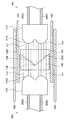
図4に示すように、光通信コネクタ10A、10Bは、その接続時において屈折部13A、13Bが対称的にかつ平面131A、131Bが対向するように配置される。この場合において、まず、光伝送路202Aから放出された光は、レンズ部11Aにおいてコリメートされ平行光LA1となる。次いで、平行光LA1は、屈折部13Aに入射するとともに屈折面133Aにより屈折されて屈折光LA2となる。次いで、屈折光LA2は、平面131Aを通過して平面131Bより屈折部13Bに入射する。入射した屈折光LA2は、屈折面133Bにおいて再度屈折されてLA1と平行な平行光LA3となる。平行光LA3は、レンズ部11Bにおいて集光され、光伝送路202Bに搬送される。As shown in FIG. 4, the
同様に、光伝送路202Bから放出された光は、レンズ部11Bにおいてコリメートされ平行光LB1となる。次いで、平行光LB1は、屈折部13Bに入射するとともに屈折面133Bにより屈折されて屈折光LB2となる。次いで、屈折光LB2は、平面131Bを通過して平面131Aより屈折部13Aに入射する。入射した屈折光LB2は、屈折面133Aにおいて再度屈折されてLB1と平行な平行光LB3となる。平行光LB3は、レンズ部11Aにおいて集光され、光伝送路202Aに伝送される。以上により、光通信コネクタ10A、10Bを介した電子機器100と光通信ケーブル200との間における光信号の双方向の伝送が可能となる。Similarly, the light emitted from the
また、光通信コネクタ10A、10Bは、屈折部13A、13Bが先端側に配置されることにより、コリメートレンズ111A、111Bおよび光伝送路202A、202Bが外部環境に露出していない。したがって、光伝送路202A、202B、コリメートレンズ111A、111Bへの塵、埃の侵入が防止されるとともに、油等の付着が防止される結果、これらのクリーニングが不要となり、メンテナンス性に優れている。さらに、屈折部13A、13Bは、その先端側が平面131A、131Bをなすため、塵、埃等の汚れが蓄積しにくい。
Further, in the
さらに、光通信コネクタ10A、10Bは、光伝送路202A、202B間の光の伝送を担う屈折部13A、13Bおよびレンズ部11A、11Bがそれぞれ同一形状である。したがって、光通信コネクタ10Aおよび光通信コネクタ10Bを含む光通信コネクタセットを製造する際には、高い寸法精度が要求される部品を共通して製造することが可能である。したがって、このような光通信コネクタセットの光結合の品質を高いものとすることができる。
Further, in the
上述したような光通信コネクタ10A、10Bは、メンテナンス性に優れるとともに、コリメート光結合を行うことができるものである。また、光通信コネクタ10A、10Bは、平行光を遮蔽するための可動部材を有さないため、機構が簡素であるとともに、故障がしにくいものとなっている。したがって、光通信コネクタ10A、10Bは、比較的頻繁に光通信ケーブル200の挿抜が行われる民生用の光通信用途に適している。
The
(電子機器)
次に、本実施形態に係る電子機器100の構成について説明する。図1に示すように、また上述したように、電子機器100は、光送受信部110を備えている。光送受信部110は、光信号の発光部120と、光信号の受光部130と、レセプタクルとしての光通信コネクタ10Bとを備えている。(Electronics)
Next, the configuration of the
発光部120は、電子機器100内において送信すべきデータを、光信号として出力し、発光部120の先端側に配置された光伝送路202Bを介して光通信コネクタ10Bに入力する。
The
また、受光部130は、光通信コネクタ10Bからの光信号を光伝送路202Bを介して受光し、電子機器100内のインタフェースへ出力する。
Further, the
また、電子機器100の詳細なハードウェア構成は、特に限定されないが、例えば、図5に示すようなものとすることができる。図5は、本開示の第1の実施形態に係る電子機器100のハードウェア構成を説明するためのブロック図である。
The detailed hardware configuration of the
電子機器100は、主に、CPU901と、ROM902と、RAM903と、を備える。また、電子機器100は、更に、ホストバス907と、ブリッジ909と、外部バス911と、インタフェース913と、入力装置915と、出力装置917と、ストレージ装置919と、ドライブ921と、接続ポート923と、通信装置925とを備える。
The
CPU901は、演算処理装置および制御装置として機能し、ROM902、RAM903、ストレージ装置919、またはリムーバブル記録媒体927に記録された各種プログラムに従って、電子機器100内の動作全般またはその一部を制御する。ROM902は、CPU901が使用するプログラムや演算パラメータ等を記憶する。RAM903は、CPU901が使用するプログラムや、プログラムの実行において適宜変化するパラメータ等を一次記憶する。これらはCPUバス等の内部バスにより構成されるホストバス907により相互に接続されている。
The
ホストバス907は、ブリッジ909を介して、PCI(Peripheral Component Interconnect/Interface)バスなどの外部バス911に接続されている。
The
入力装置915は、例えば、マウス、キーボード、タッチパネル、ボタン、スイッチおよびレバーなどユーザが操作する操作手段である。また、入力装置915は、例えば、赤外線やその他の電波を利用したリモートコントロール手段(いわゆる、リモコン)であってもよいし、電子機器100の操作に対応した携帯電話やPDA等の外部接続機器929であってもよい。さらに、入力装置915は、例えば、上記の操作手段を用いてユーザにより入力された情報に基づいて入力信号を生成し、CPU901に出力する入力制御回路などから構成されている。電子機器100のユーザは、この入力装置915を操作することにより、電子機器100に対して各種のデータを入力したり処理動作を指示したりすることができる。
The
出力装置917は、取得した情報をユーザに対して視覚的または聴覚的に通知することが可能な装置で構成される。このような装置として、CRTディスプレイ装置、液晶ディスプレイ装置、プラズマディスプレイ装置、ELディスプレイ装置およびランプなどの表示装置や、スピーカおよびヘッドホンなどの音声出力装置や、プリンタ装置、携帯電話、ファクシミリなどがある。出力装置917は、例えば、電子機器100が行った各種処理により得られた結果を出力する。具体的には、表示装置は、電子機器100が行った各種処理により得られた結果を、テキストまたはイメージで表示する。他方、音声出力装置は、再生された音声データや音響データ等からなるオーディオ信号をアナログ信号に変換して出力する。
The
ストレージ装置919は、電子機器100の記憶部の一例として構成されたデータ格納用の装置である。ストレージ装置919は、例えば、HDD(Hard Disk Drive)等の磁気記憶部デバイス、半導体記憶デバイス、光記憶デバイス、または光磁気記憶デバイス等により構成される。このストレージ装置919は、CPU901が実行するプログラムや各種データ、および外部から取得した各種のデータなどを格納する。
The
ドライブ921は、記録媒体用リーダライタであり、電子機器100に内蔵、あるいは外付けされる。ドライブ921は、装着されている磁気ディスク、光ディスク、光磁気ディスク、または半導体メモリ等のリムーバブル記録媒体927に記録されている情報を読み出して、RAM903に出力する。また、ドライブ921は、装着されている磁気ディスク、光ディスク、光磁気ディスク、または半導体メモリ等のリムーバブル記録媒体927に記録を書き込むことも可能である。リムーバブル記録媒体927は、例えば、DVDメディア、HD−DVDメディア、Blu−rayメディア等である。また、リムーバブル記録媒体927は、コンパクトフラッシュ(登録商標)(CompactFlash:CF)、フラッシュメモリ、または、SDメモリカード(Secure Digital memory card)等であってもよい。また、リムーバブル記録媒体927は、例えば、非接触型ICチップを搭載したICカード(Integrated Circuit card)または電子機器等であってもよい。
The
接続ポート923は、機器を電子機器100に直接接続するためのポートである。接続ポート923の一例として、USB(Universal Serial Bus)ポート、IEEE1394ポート、SCSI(Small Computer System Interface)ポート等がある。接続ポート923の別の例として、RS−232Cポート、光デジタル端子、HDMI(High−Definition Multimedia Interface)ポート等がある。この接続ポート923に外部接続機器929を接続することで、電子機器100は、外部接続機器929から直接各種のデータを取得したり、外部接続機器929に各種のデータを提供したりする。なお、上記の光デジタル端子を上述した光通信コネクタ10Bを含む光送受信部110として構成してもよい。
The
通信装置925は、例えば、通信網931に接続するための通信デバイス等で構成された通信インタフェースである。本実施形態において、通信装置925は、上述した光通信コネクタ10Bを含む光送受信部110を含んで構成されている。通信装置925は、光通信用のルータであってもよい。また、通信装置925は、例えば、有線または無線LAN(Local Area Network)、Bluetooth(登録商標)、またはWUSB(Wireless USB)用の通信カード等をさらに含んでもよい。また、通信装置925は、DSL(Asymmetric Digital Subscriber Line)用のルータ、または、各種通信用のモデム等を含んで構成されていてもよい。この通信装置925は、例えば、インターネットや他の通信機器との間で、例えばFTTR、FTTB、FTTH、FTTD等のFTTxや、TCP/IP等の所定のプロトコルに則して信号等を送受信することができる。また、通信装置925に接続される通信網931は、有線または無線によって接続されたネットワーク等により構成され、例えば、インターネット、家庭内LAN、赤外線通信、ラジオ波通信または衛星通信等であってもよい。
The
(光通信ケーブル)
光通信ケーブル200は、ケーブル本体201と、光通信コネクタ10Aとを備えている。ケーブル本体201は、内部に光伝送路202Aを有している。光伝送路202Aは、例えば、光ファイバである。なお、光伝送路202Aは、光を伝送可能なものであれば特に限定されず、光ファイバ以外のものであってもよい。光伝送路202Aは、その外周面に適宜被覆がなされている。また、光伝送路202Aの先端側には光通信コネクタ10Aが接続されている。(Optical communication cable)
The
このような光通信ケーブル200は、上述したような電子機器100等の電子機器と他の機器との間の光通信のための接続に使用されることができる。
Such an
<2.第2の実施形態>
以下では、図6〜8を参照しながら、本開示の第2の実施形態について詳細に説明する。<2. Second embodiment>
Hereinafter, the second embodiment of the present disclosure will be described in detail with reference to FIGS. 6 to 8.
図6は、本開示の第2の実施形態に係る光通信コネクタ10Cの拡大断面図、図7は、本開示の第2の実施形態に係る光通信コネクタ10Dの拡大断面図、図8は、図6および図7に示す光通信コネクタ10Cおよび10Dの接続状態を示す拡大断面図である。本実施形態に係る光通信コネクタ10Cおよび10Dは、屈折部13Cおよび13Dの形状が異なり、これに伴い光伝送路202C、202Dからの光の光路が異なる点で、第1の実施形態に係る光通信コネクタ10A、10Bと相違する。また、本実施形態に係る電子機器および光通信ケーブルにおける第1の実施形態に係る電子機器100および光通信ケーブル200との相違点は、光通信コネクタ10Cおよび10Dに関しての相違点のみである。以下、本実施形態の第1の実施形態との相違点を主として説明し、同様の事項については説明を省略する。
FIG. 6 is an enlarged cross-sectional view of the
図6に示す光通信コネクタ10Cの屈折部13Cは、レンズ部11Cより射出された平行光LC1を屈折させて屈折光LC2を射出するように構成・配置されたプリズムである。屈折部13Cは、レンズ部11Cよりも先端側に配置されている。また、屈折部13Cは、レンズ部11Cに配置された各コリメートレンズ111Cからの平行光LC1を受光できるように、適宜幅方向(図中奥行方向)に延長されている。なお、図示の態様に限定されず、屈折部13Cは、コリメートレンズ111Cの配置に対応して厚さ方向に延長または短縮されることもできる。Refraction portion of the
屈折部13Cは、その基端側、平行光LC1の入射側の面が、平行光LC1と略垂直となるような平面137Cをなしている。これにより、屈折部13Cに入射する平行光LC1は、屈折部13C内において屈折を受けずに進む。
一方で、屈折部13Cは、その先端側、すなわち屈折部13Cの出射側の面が、コリメートレンズ111Cからの入射光(平行光LC1)に対して互いに角度の異なる複数の屈折面135Cを含んで構成されている。本実施形態では、屈折部13Cは、先端側に2つの屈折面135Cを有し、これらにより中心線138を頂点とする凸部が形成されている。これにより、屈折面135Cに侵入した平行光LC1は屈折され、中心線138より外側に向かう屈折光LC2となる。なお、屈折光Lc2は、その進行方向上にある散乱部材15Cの散乱部151Cにおいて散乱される。On the other hand, the refracting
なお、屈折面135Cには、反射防止部および/または表面保護部が形成されていてもよい。
また、屈折部13Cの構成材料は、上述した屈折部13Aの構成材料と同様であることができる。The
Further, the constituent material of the refracting
図7に示す光通信コネクタ10Dの屈折部13Dも、レンズ部11Dより射出された平行光LD1を屈折させて屈折光LD2を射出するように構成・配置されたプリズムである。また、屈折部13Dは、レンズ部11Dに配置された各コリメートレンズ111Dからの平行光LD1を受光できるように、適宜幅方向(図中奥行方向)に適宜延長されている。なお、図示の態様に限定されず、屈折部13Dは、コリメートレンズ111Dの配置に対応して厚さ方向に延長または短縮されることもできる。The refracting
屈折部13Dは、その基端側、平行光LD1の入射側の面が、平行光LD1と略垂直となるような平面137Dをなしている。これにより、屈折部13Dに入射する平行光LD1は、屈折部13D内において屈折を受けずに進む。The refracting
一方で、屈折部13Dは、その先端側、すなわち屈折部13Dの出射側の面が、コリメートレンズ111Dからの入射光(平行光LD1)に対して互いに角度の異なる複数の屈折面135Dを含んで構成されている。本実施形態では、屈折部13Dは、先端側に2つの屈折面135Dを有し、これらにより中心線139を底部とする凹部が形成されている。これにより、屈折面135Dに侵入した平行光LD1は屈折され、中心線139側に向かう屈折光LD2となる。なお、屈折光LD2は、その進行方向上にある散乱部材15Dの散乱部151Dにおいて散乱される。On the other hand, the
また、屈折部13Dの屈折面135Dは、接続時において対向する屈折部13Cの屈折面135Cと対応する形状、例えば面積、角度等を有している。このような屈折面135Dは、図8に示すように、屈折部13Cの屈折面135Cにより射出された屈折光(図6における屈折光LC2)を再び屈折させて平行光LC3とし、コリメートレンズ111Dに伝送することができる。Further, the refracting
また、屈折面135Dには、反射防止部および/または表面保護部が形成されていてもよい。
また、屈折部13Dの構成材料は、上述した屈折部13Aの構成材料と同様であることができる。Further, the refracting
Further, the constituent material of the refracting
以上のような光通信コネクタ10Cおよび10Dは、上述したように、屈折部13C、13Dおよび散乱部151C、151Dにより、互いに接続していない場合、すなわち非光結合時において、平行光が光通信コネクタ10C、10D外に直接放射されることが防止されている。一方で、図8に示すように、また以下に説明するように、光通信コネクタ10C、10Dが接続された際には、2つの屈折部13C、13Dを通過した光信号は再び平行光となり、光結合が可能となる。
As described above, the
図8に示すように、光通信コネクタ10C、10Dは、その接続時において屈折部13C、13Cの屈折面135C、135Dがそれぞれ対向するように配置される。この場合において、まず、光伝送路202Cから放出された光は、レンズ部11Cにおいてコリメートされ平行光LC1となる。次いで、平行光LC1は、屈折部13Cに入射するとともに屈折面135Cにより屈折されて屈折部13Cから射出される。次いで、屈折された光は、直ちに対向する屈折部13Dの屈折面135Dに入射するとともに再度屈折されLC1と平行な平行光LC3となる。平行光LC3は、レンズ部11Dにおいて集光され、光伝送路202Dに搬送される。As shown in FIG. 8, the
同様に、光伝送路202Dから放出された光は、レンズ部11Dにおいてコリメートされ平行光LD1となる。次いで、平行光LD1は、屈折部13Dに入射するとともに屈折面135Dにより屈折されて屈折部13Dから射出される。次いで、屈折された光は、直ちに対向する屈折部13Cの屈折面135Cに入射するとともに再度屈折されLD1と平行な平行光LD3となる。平行光LD3は、レンズ部11Cにおいて集光され、光伝送路202Cに搬送される。以上により、光通信コネクタ10C、10Dを介した電子機器と光通信ケーブルとの間における光信号の双方向の伝送が可能となる。Similarly, light emitted from the
また、光通信コネクタ10C、10Dは、屈折部13C、13Dが先端側に配置されることにより、コリメートレンズ111C、111Dおよび光伝送路202C、202Dが外部環境に露出していない。したがって、光伝送路202C、202D、コリメートレンズ111C、111Dのクリーニングが不要となり、メンテナンス性に優れている。さらに、屈折部13A、13Bは、その先端側が凹凸をなすため、接続時の光通信コネクタ10C、10D同士の位置合わせが容易である。
Further, in the
<3.応用例>
本開示に係る技術は、様々な製品へ応用することができる。例えば、本開示に係る技術は、自動車、電気自動車、ハイブリッド電気自動車、自動二輪車などのいずれかの種類の車両に搭載される装置として実現されてもよい。<3. Application example>
The technology according to the present disclosure can be applied to various products. For example, the technology according to the present disclosure may be realized as a device mounted on any type of vehicle such as an automobile, an electric vehicle, a hybrid electric vehicle, and a motorcycle.
図9は、本開示に係る技術が適用され得る車両制御システム2000の概略的な構成の一例を示すブロック図である。車両制御システム2000は、通信ネットワーク2010を介して接続された複数の電子制御ユニットを備える。図9に示した例では、車両制御システム2000は、駆動系制御ユニット2100、ボディ系制御ユニット2200、バッテリ制御ユニット2300、車外情報検出ユニット2400、車内情報検出ユニット2500、及び統合制御ユニット2600を備える。これらの複数の制御ユニットを接続する通信ネットワーク2010は、例えば、CAN(Controller Area Network)、LIN(Local Interconnect Network)、LAN(Local Area Network)又はFlexRay(登録商標)等の任意の規格に準拠した車載通信ネットワークであってよい。
FIG. 9 is a block diagram showing an example of a schematic configuration of a
各制御ユニットは、各種プログラムにしたがって演算処理を行うマイクロコンピュータと、マイクロコンピュータにより実行されるプログラム又は各種演算に用いられるパラメータ等を記憶する記憶部と、各種制御対象の装置を駆動する駆動回路とを備える。各制御ユニットは、通信ネットワーク2010を介して他の制御ユニットとの間で通信を行うためのネットワークI/Fを備えるとともに、車内外の装置又はセンサ等との間で、有線通信又は無線通信により通信を行うための通信I/Fを備える。図9では、統合制御ユニット2600の機能構成として、マイクロコンピュータ2610、汎用通信I/F2620、専用通信I/F2630、測位部2640、ビーコン受信部2650、車内機器I/F2660、音声画像出力部2670、車載ネットワークI/F2680及び記憶部2690が図示されている。他の制御ユニットも同様に、マイクロコンピュータ、通信I/F及び記憶部等を備える。
Each control unit includes a microcomputer that performs arithmetic processing according to various programs, a storage unit that stores a program executed by the microcomputer or parameters used for various arithmetics, and a drive circuit that drives various control target devices. To be equipped. Each control unit is provided with a network I / F for communicating with other control units via the
駆動系制御ユニット2100は、各種プログラムにしたがって車両の駆動系に関連する装置の動作を制御する。例えば、駆動系制御ユニット2100は、内燃機関又は駆動用モータ等の車両の駆動力を発生させるための駆動力発生装置、駆動力を車輪に伝達するための駆動力伝達機構、車両の舵角を調節するステアリング機構、及び、車両の制動力を発生させる制動装置等の制御装置として機能する。駆動系制御ユニット2100は、ABS(Antilock Brake System)又はESC(Electronic Stability Control)等の制御装置としての機能を有してもよい。
The drive
駆動系制御ユニット2100には、車両状態検出部2110が接続される。車両状態検出部2110には、例えば、車体の軸回転運動の角速度を検出するジャイロセンサ、車両の加速度を検出する加速度センサ、あるいは、アクセルペダルの操作量、ブレーキペダルの操作量、ステアリングホイールの操舵角、エンジン回転数又は車輪の回転速度等を検出するためのセンサのうちの少なくとも一つが含まれる。駆動系制御ユニット2100は、車両状態検出部2110から入力される信号を用いて演算処理を行い、内燃機関、駆動用モータ、電動パワーステアリング装置又はブレーキ装置等を制御する。
The vehicle
ボディ系制御ユニット2200は、各種プログラムにしたがって車体に装備された各種装置の動作を制御する。例えば、ボディ系制御ユニット2200は、キーレスエントリシステム、スマートキーシステム、パワーウィンドウ装置、あるいは、ヘッドランプ、バックランプ、ブレーキランプ、ウィンカー又はフォグランプ等の各種ランプの制御装置として機能する。この場合、ボディ系制御ユニット2200には、鍵を代替する携帯機から発信される電波又は各種スイッチの信号が入力され得る。ボディ系制御ユニット2200は、これらの電波又は信号の入力を受け付け、車両のドアロック装置、パワーウィンドウ装置、ランプ等を制御する。
The body
バッテリ制御ユニット2300は、各種プログラムにしたがって駆動用モータの電力供給源である二次電池2310を制御する。例えば、バッテリ制御ユニット2300には、二次電池2310を備えたバッテリ装置から、バッテリ温度、バッテリ出力電圧又はバッテリの残存容量等の情報が入力される。バッテリ制御ユニット2300は、これらの信号を用いて演算処理を行い、二次電池2310の温度調節制御又はバッテリ装置に備えられた冷却装置等の制御を行う。
The
車外情報検出ユニット2400は、車両制御システム2000を搭載した車両の外部の情報を検出する。例えば、車外情報検出ユニット2400には、撮像部2410及び車外情報検出部2420のうちの少なくとも一方が接続される。撮像部2410には、ToF(Time Of Flight)カメラ、ステレオカメラ、単眼カメラ、赤外線カメラ及びその他のカメラのうちの少なくとも一つが含まれる。車外情報検出部2420には、例えば、現在の天候又は気象を検出するための環境センサ、あるいは、車両制御システム2000を搭載した車両の周囲の他の車両、障害物又は歩行者等を検出するための周囲情報検出センサが含まれる。
The vehicle outside
環境センサは、例えば、雨天を検出する雨滴センサ、霧を検出する霧センサ、日照度合いを検出する日照センサ、及び降雪を検出する雪センサのうちの少なくとも一つであってよい。周囲情報検出センサは、超音波センサ、レーダ装置及びLIDAR(Light Detection and Ranging、Laser Imaging Detection and Ranging)装置のうちの少なくとも一つであってよい。これらの撮像部2410及び車外情報検出部2420は、それぞれ独立したセンサないし装置として備えられてもよいし、複数のセンサないし装置が統合された装置として備えられてもよい。
The environment sensor may be, for example, at least one of a raindrop sensor that detects rainy weather, a fog sensor that detects fog, a sunshine sensor that detects the degree of sunshine, and a snow sensor that detects snowfall. The ambient information detection sensor may be at least one of an ultrasonic sensor, a radar device, and a LIDAR (Light Detection and Ranging, Laser Imaging Detection and Ranging) device. The
ここで、図10は、撮像部2410及び車外情報検出部2420の設置位置の例を示す。撮像部2910,2912,2914,2916,2918は、例えば、車両2900のフロントノーズ、サイドミラー、リアバンパ、バックドア及び車室内のフロントガラスの上部のうちの少なくとも一つの位置に設けられる。フロントノーズに備えられる撮像部2910及び車室内のフロントガラスの上部に備えられる撮像部2918は、主として車両2900の前方の画像を取得する。サイドミラーに備えられる撮像部2914,2912は、主として車両2900の側方の画像を取得する。リアバンパ又はバックドアに備えられる撮像部2916は、主として車両2900の後方の画像を取得する。車室内のフロントガラスの上部に備えられる撮像部2918は、主として先行車両又は、歩行者、障害物、信号機、交通標識又は車線等の検出に用いられる。
Here, FIG. 10 shows an example of the installation positions of the
なお、図10には、それぞれの撮像部2910,2912,2914,2916の撮影範囲の一例が示されている。撮像範囲aは、フロントノーズに設けられた撮像部2910の撮像範囲を示し、撮像範囲b,cは、それぞれサイドミラーに設けられた撮像部2912,2914の撮像範囲を示し、撮像範囲dは、リアバンパ又はバックドアに設けられた撮像部2916の撮像範囲を示す。例えば、撮像部2910,2912,2914,2916で撮像された画像データが重ね合わせられることにより、車両2900を上方から見た俯瞰画像が得られる。
Note that FIG. 10 shows an example of the photographing range of each of the
車両2900のフロント、リア、サイド、コーナ及び車室内のフロントガラスの上部に設けられる車外情報検出部2920,2922,2924,2926,2928,2930は、例えば超音波センサ又はレーダ装置であってよい。車両2900のフロントノーズ、リアバンパ、バックドア及び車室内のフロントガラスの上部に設けられる車外情報検出部2920,2926,2930は、例えばLIDAR装置であってよい。これらの車外情報検出部2920〜2930は、主として先行車両、歩行者又は障害物等の検出に用いられる。
The vehicle exterior
図9に戻って説明を続ける。車外情報検出ユニット2400は、撮像部2410に車外の画像を撮像させるとともに、撮像された画像データを受信する。また、車外情報検出ユニット2400は、接続されている車外情報検出部2420から検出情報を受信する。車外情報検出部2420が超音波センサ、レーダ装置又はLIDAR装置である場合には、車外情報検出ユニット2400は、超音波又は電磁波等を発信させるとともに、受信された反射波の情報を受信する。車外情報検出ユニット2400は、受信した情報に基づいて、人、車、障害物、標識又は路面上の文字等の物体検出処理又は距離検出処理を行ってもよい。車外情報検出ユニット2400は、受信した情報に基づいて、降雨、霧又は路面状況等を認識する環境認識処理を行ってもよい。車外情報検出ユニット2400は、受信した情報に基づいて、車外の物体までの距離を算出してもよい。
The explanation will be continued by returning to FIG. The vehicle exterior
また、車外情報検出ユニット2400は、受信した画像データに基づいて、人、車、障害物、標識又は路面上の文字等を認識する画像認識処理又は距離検出処理を行ってもよい。車外情報検出ユニット2400は、受信した画像データに対して歪補正又は位置合わせ等の処理を行うとともに、異なる撮像部2410により撮像された画像データを合成して、俯瞰画像又はパノラマ画像を生成してもよい。車外情報検出ユニット2400は、異なる撮像部2410により撮像された画像データを用いて、視点変換処理を行ってもよい。
Further, the vehicle exterior
車内情報検出ユニット2500は、車内の情報を検出する。車内情報検出ユニット2500には、例えば、運転者の状態を検出する運転者状態検出部2510が接続される。運転者状態検出部2510は、運転者を撮像するカメラ、運転者の生体情報を検出する生体センサ又は車室内の音声を集音するマイク等を含んでもよい。生体センサは、例えば、座面又はステアリングホイール等に設けられ、座席に座った搭乗者又はステアリングホイールを握る運転者の生体情報を検出する。車内情報検出ユニット2500は、運転者状態検出部2510から入力される検出情報に基づいて、運転者の疲労度合い又は集中度合いを算出してもよいし、運転者が居眠りをしていないかを判別してもよい。車内情報検出ユニット2500は、集音された音声信号に対してノイズキャンセリング処理等の処理を行ってもよい。
The in-vehicle
統合制御ユニット2600は、各種プログラムにしたがって車両制御システム2000内の動作全般を制御する。統合制御ユニット2600には、入力部2800が接続されている。入力部2800は、例えば、タッチパネル、ボタン、マイクロフォン、スイッチ又はレバー等、搭乗者によって入力操作され得る装置によって実現される。入力部2800は、例えば、赤外線又はその他の電波を利用したリモートコントロール装置であってもよいし、車両制御システム2000の操作に対応した携帯電話又はPDA(Personal Digital Assistant)等の外部接続機器であってもよい。入力部2800は、例えばカメラであってもよく、その場合搭乗者はジェスチャにより情報を入力することができる。さらに、入力部2800は、例えば、上記の入力部2800を用いて搭乗者等により入力された情報に基づいて入力信号を生成し、統合制御ユニット2600に出力する入力制御回路などを含んでもよい。搭乗者等は、この入力部2800を操作することにより、車両制御システム2000に対して各種のデータを入力したり処理動作を指示したりする。
The
記憶部2690は、マイクロコンピュータにより実行される各種プログラムを記憶するROM(Read Only Memory)、及び各種パラメータ、演算結果又はセンサ値等を記憶するRAM(Random Access Memory)を含んでいてもよい。また、記憶部2690は、HDD(Hard Disc Drive)等の磁気記憶デバイス、半導体記憶デバイス、光記憶デバイス又は光磁気記憶デバイス等によって実現してもよい。
The
汎用通信I/F2620は、外部環境2750に存在する様々な機器との間の通信を仲介する汎用的な通信I/Fである。汎用通信I/F2620は、GSM(Global System of Mobile communications)、WiMAX、LTE(Long Term Evolution)若しくはLTE−A(LTE−Advanced)などのセルラー通信プロトコル、又は無線LAN(Wi−Fi(登録商標)ともいう)などのその他の無線通信プロトコルを実装してよい。汎用通信I/F2620は、例えば、基地局又はアクセスポイントを介して、外部ネットワーク(例えば、インターネット、クラウドネットワーク又は事業者固有のネットワーク)上に存在する機器(例えば、アプリケーションサーバ又は制御サーバ)へ接続してもよい。また、汎用通信I/F2620は、例えばP2P(Peer To Peer)技術を用いて、車両の近傍に存在する端末(例えば、歩行者若しくは店舗の端末、又はMTC(Machine Type Communication)端末)と接続してもよい。
The general-purpose communication I /
専用通信I/F2630は、車両における使用を目的として策定された通信プロトコルをサポートする通信I/Fである。専用通信I/F2630は、例えば、下位レイヤのIEEE802.11pと上位レイヤのIEEE1609との組合せであるWAVE(Wireless Access in Vehicle Environment)、又はDSRC(Dedicated Short Range Communications)といった標準プロトコルを実装してよい。専用通信I/F2630は、典型的には、車車間(Vehicle to Vehicle)通信、路車間(Vehicle to Infrastructure)通信及び歩車間(Vehicle to Pedestrian)通信のうちの1つ以上を含む概念であるV2X通信を遂行する。
The dedicated communication I /
測位部2640は、例えば、GNSS(Global Navigation Satellite System)衛星からのGNSS信号(例えば、GPS(Global Positioning System)衛星からのGPS信号)を受信して測位を実行し、車両の緯度、経度及び高度を含む位置情報を生成する。なお、測位部2640は、無線アクセスポイントとの信号の交換により現在位置を特定してもよく、又は測位機能を有する携帯電話、PHS若しくはスマートフォンといった端末から位置情報を取得してもよい。
The
ビーコン受信部2650は、例えば、道路上に設置された無線局等から発信される電波あるいは電磁波を受信し、現在位置、渋滞、通行止め又は所要時間等の情報を取得する。なお、ビーコン受信部2650の機能は、上述した専用通信I/F2630に含まれてもよい。
The
車内機器I/F2660は、マイクロコンピュータ2610と車内に存在する様々な機器との間の接続を仲介する通信インタフェースである。車内機器I/F2660は、無線LAN、Bluetooth(登録商標)、NFC(Near Field Communication)又はWUSB(Wireless USB)といった無線通信プロトコルを用いて無線接続を確立してもよい。また、車内機器I/F2660は、図示しない接続端子(及び、必要であればケーブル)を介して有線接続を確立してもよい。車内機器I/F2660は、例えば、搭乗者が有するモバイル機器若しくはウェアラブル機器、又は車両に搬入され若しくは取り付けられる情報機器との間で、制御信号又はデータ信号を交換する。
The in-vehicle device I /
車載ネットワークI/F2680は、マイクロコンピュータ2610と通信ネットワーク2010との間の通信を仲介するインタフェースである。車載ネットワークI/F2680は、通信ネットワーク2010によりサポートされる所定のプロトコルに則して、信号等を送受信する。
The vehicle-mounted network I / F2680 is an interface that mediates communication between the
統合制御ユニット2600のマイクロコンピュータ2610は、汎用通信I/F2620、専用通信I/F2630、測位部2640、ビーコン受信部2650、車内機器I/F2660及び車載ネットワークI/F2680のうちの少なくとも一つを介して取得される情報に基づき、各種プログラムにしたがって、車両制御システム2000を制御する。例えば、マイクロコンピュータ2610は、取得される車内外の情報に基づいて、駆動力発生装置、ステアリング機構又は制動装置の制御目標値を演算し、駆動系制御ユニット2100に対して制御指令を出力してもよい。例えば、マイクロコンピュータ2610は、車両の衝突回避あるいは衝撃緩和、車間距離に基づく追従走行、車速維持走行、自動運転等を目的とした協調制御を行ってもよい。
The
マイクロコンピュータ2610は、汎用通信I/F2620、専用通信I/F2630、測位部2640、ビーコン受信部2650、車内機器I/F2660及び車載ネットワークI/F2680のうちの少なくとも一つを介して取得される情報に基づき、車両の現在位置の周辺情報を含むローカル地図情報を作成してもよい。また、マイクロコンピュータ2610は、取得される情報に基づき、車両の衝突、歩行者等の近接又は通行止めの道路への進入等の危険を予測し、警告用信号を生成してもよい。警告用信号は、例えば、警告音を発生させたり、警告ランプを点灯させたりするための信号であってよい。
The
音声画像出力部2670は、車両の搭乗者又は車外に対して、視覚的又は聴覚的に情報を通知することが可能な出力装置へ音声及び画像のうちの少なくとも一方の出力信号を送信する。図9の例では、出力装置として、オーディオスピーカ2710、表示部2720及びインストルメントパネル2730が例示されている。表示部2720は、例えば、オンボードディスプレイ及びヘッドアップディスプレイの少なくとも一つを含んでいてもよい。表示部2720は、AR(Augmented Reality)表示機能を有していてもよい。出力装置は、これらの装置以外の、ヘッドホン、プロジェクタ又はランプ等の他の装置であってもよい。出力装置が表示装置の場合、表示装置は、マイクロコンピュータ2610が行った各種処理により得られた結果又は他の制御ユニットから受信された情報を、テキスト、イメージ、表、グラフ等、様々な形式で視覚的に表示する。また、出力装置が音声出力装置の場合、音声出力装置は、再生された音声データ又は音響データ等からなるオーディオ信号をアナログ信号に変換して聴覚的に出力する。
The audio-
なお、図9に示した例において、通信ネットワーク2010を介して接続された少なくとも二つの制御ユニットが一つの制御ユニットとして一体化されてもよい。あるいは、個々の制御ユニットが、複数の制御ユニットにより構成されてもよい。さらに、車両制御システム2000が、図示されていない別の制御ユニットを備えてもよい。また、上記の説明において、いずれかの制御ユニットが担う機能の一部又は全部を、他の制御ユニットに持たせてもよい。つまり、通信ネットワーク2010を介して情報の送受信がされるようになっていれば、所定の演算処理が、いずれかの制御ユニットで行われるようになってもよい。同様に、いずれかの制御ユニットに接続されているセンサ又は装置が、他の制御ユニットに接続されるとともに、複数の制御ユニットが、通信ネットワーク2010を介して相互に検出情報を送受信してもよい。
In the example shown in FIG. 9, at least two control units connected via the
以上説明した車両制御システム2000において、図1〜図8を用いて説明した光通信コネクタ10A〜10Dは、図9に示した各種インタフェースに適用することができる。例えば、光通信コネクタ10A〜10Dは、汎用通信I/F2620、専用通信I/F2630、車内機器I/F2660、音声画像出力部2670、車載ネットワークI/F2680や、これに対応する外部環境2750、車内機器2760、オーディオスピーカ2710、表示部2720、インストルメントパネル2730、通信ネットワーク2010等における通信コネクタとして適用可能である。また、本開示に係る電子機器、例えば電子機器100は、例えば統合制御ユニット2600に適用することができる。さらに、本開示に係る光通信ケーブル、例えば光通信ケーブル200は、通信ネットワーク2010の他、車両制御システム2000内外の各インタフェースおよび機器との接続に適用可能である。
In the
また、図1、図5を用いて説明した電子機器100の少なくとも一部の構成要素は、図9に示した統合制御ユニット2600のためのモジュール(例えば、一つのダイで構成される集積回路モジュール)において実現されてもよい。あるいは、図5を用いて説明した電子機器100が、図9に示した車両制御システム2000の複数の制御ユニットによって実現されてもよい。
Further, at least a part of the components of the
以上、添付図面を参照しながら本開示の好適な実施形態について詳細に説明したが、本開示の技術的範囲はかかる例に限定されない。本開示の技術分野における通常の知識を有する者であれば、特許請求の範囲に記載された技術的思想の範疇内において、各種の変更例または修正例に想到し得ることは明らかであり、これらについても、当然に本開示の技術的範囲に属するものと了解される。 Although the preferred embodiments of the present disclosure have been described in detail with reference to the accompanying drawings, the technical scope of the present disclosure is not limited to such examples. It is clear that a person having ordinary knowledge in the technical field of the present disclosure can come up with various modifications or modifications within the scope of the technical ideas described in the claims. Of course, it is understood that the above also belongs to the technical scope of the present disclosure.
例えば、上述した実施形態においては、光通信コネクタ10Aが光通信ケーブル200に、光通信コネクタ10Bが、電子機器100に配置されているものとして説明したが、光通信コネクタ10A、10Bの配置は上記に限定されない。例えば、光通信コネクタ10Aが電子機器100に、光通信コネクタ10Bが、光通信ケーブル200に配置されていてもよい。光通信コネクタ10C、10Dについても同様である。
For example, in the above-described embodiment, the
また、光通信コネクタ10A〜10Dの屈折部13A〜10Dの形状は、コリメートレンズ111A〜111Dからの平行光LA1〜LD1を屈折できるものであれば図示の態様に限定されない。屈折部の屈折面の数は、例えば、そのコリメートレンズからの光信号の数に応じて、1または複数とすることができる。The shape of the
また、図示の態様では、光通信コネクタ10Aと光通信コネクタ10Bとの接続時において平面131A、131Bが当接するものとして説明したが、本開示に係る構成はこれに限定されない。例えば、光通信コネクタ10Aと光通信コネクタ10Bとの接続時において平面131A、131Bは、離間していることができる。この場合において、屈折面133A、133Bの傾斜角を適宜調節して、屈折部13A、13B内における光路を適宜調節してもよい。
Further, in the illustrated embodiment, the
同様に、図示の態様では、光通信コネクタ10Cと光通信コネクタ10Dとの接続時において屈折面135C、135Dが当接するものとして説明したが、本開示に係る構成はこれに限定されない。例えば、光通信コネクタ10Cと光通信コネクタ10Dとの接続時において屈折面135C、135Dは、離間していることができる。この場合において、屈折面135C、135Dの傾斜角を適宜調節して、屈折部13C、13Dにおける光路を適宜調節してもよい。
また、上述した実施形態では、反射防止部は、屈折部13A〜13Dの光の出射側(先端側)にあるものとして説明したが、本開示に係る構成はこれに限定されない。反射防止部は、例えば屈折部の光の入射側(基端側)にも配置することができる。Similarly, in the illustrated embodiment, the refracting
Further, in the above-described embodiment, the antireflection portion has been described as being on the light emitting side (tip side) of the refracting
また、図示の態様では、光通信コネクタ10A〜10Dの散乱部151A〜151Dは、屈折光LA2〜LD2の全部を散乱させるものとして説明したが、本開示に係る構成はこれに限定されない。例えば、散乱部151A〜151Dは、屈折光LA2〜LD2の一部のみを散乱させるものであってもよい。例えば、散乱部151A〜151Dの屈折光LA2〜LD2を散乱させる程度は、上述した国際規格(IEC 60825−1、2)を満たすように適宜調整可能である。Further, in the illustrated embodiment, the scattering
また、本明細書に記載された効果は、あくまで説明的または例示的なものであって限定的ではない。つまり、本開示に係る技術は、上記の効果とともに、または上記の効果に代えて、本明細書の記載から当業者には明らかな他の効果を奏しうる。 In addition, the effects described herein are merely explanatory or exemplary and are not limited. That is, the techniques according to the present disclosure may exhibit other effects apparent to those skilled in the art from the description herein, in addition to or in place of the above effects.
なお、以下のような構成も本開示の技術的範囲に属する。
(1) 光伝送路からの光をコリメートするコリメートレンズと、
前記コリメートレンズより先端側に配置され、前記コリメートレンズから射出された前記光伝送路からの光を屈折させて射出する屈折部と、
前記屈折部から射出された光の少なくとも一部を散乱させる散乱部と、を備える、光通信コネクタ。
(2) 前記屈折部は、光の射出側の面が、平面をなしている、(1)に記載の光通信コネクタ。
(3) 前記屈折部は、光の入射側の面が、前記コリメートレンズからの入射光に対して互いに角度の異なる複数の屈折面を含んで構成されており、
前記複数の屈折面は、前記コリメートレンズによりコリメートされた前記光伝送路からの光を、互いに交差するように屈折させる、(1)または(2)に記載の光通信コネクタ。
(4) 前記屈折部は、光の入射側に2つの屈折面を有し、
前記2つの屈折面により凸部が形成される、(1)〜(3)のいずれか一項に記載の光通信コネクタ。
(5) 前記屈折部と同一形状の他の屈折部を備える第2の光通信コネクタを、前記屈折部と前記他の屈折部とが前記屈折部の射出側面にて対称的に対向するように、接続した際に、
前記屈折部から射出されて前記他の屈折部を通過した光が、前記コリメートレンズから射出された光と平行な平行光となるように構成されている、(1)〜(4)のいずれか一項に記載の光通信コネクタ。
(6) 前記屈折部は、その光の出射側の面が、前記コリメートレンズからの入射光に対して互いに角度の異なる複数の屈折面を含んで構成されている、(1)に記載の光通信コネクタ。
(7) 前記屈折部は、光の出射側に2つの屈折面を有し、
前記2つの屈折面により凸部または凹部が形成される、(6)に記載の光通信コネクタ。
(8) 前記屈折部の前記屈折面の形状に対応する他の屈折面を有する他の屈折部を備える第2の光通信コネクタを、前記屈折面と前記他の屈折面とが対向するように接続した際に、
前記屈折部から射出されて前記他の屈折部を通過した光が、前記コリメートレンズから射出された光と平行な平行光となるように構成されている、(6)または(7)に記載の光通信コネクタ。
(9) 前記屈折部は、プリズムである、(1)〜(8)のいずれか一項に記載の光通信コネクタ。
(10) 前記屈折部は、反射防止部を有する、(1)〜(9)のいずれか一項に記載の光通信コネクタ。
(11) 前記屈折部は、光の出射側の面に表面保護部を有する、(1)〜(10)のいずれか一項に記載の光通信コネクタ。
(12) 前記屈折部は、ボリカーボネートを含んで構成されている、(1)〜(11)のいずれか一項に記載の光通信コネクタ。
(13) 前記散乱部は、アルマイト層を含んで構成されている、(1)〜(12)のいずれか一項に記載の光通信コネクタ。
(14) 光伝送路と、
前記光伝送路からの光をコリメートするコリメートレンズと、前記コリメートレンズより先端側に配置され、前記コリメートレンズを通過した前記光伝送路からの光を屈折させて射出する屈折部と、前記屈折部から射出された光の少なくとも一部を散乱させる散乱部とを備える光通信コネクタと、
を備える、光通信ケーブル。
(15) 光伝送路からの光をコリメートするコリメートレンズと、前記コリメートレンズより先端側に配置され、前記コリメートレンズを通過した前記光伝送路からの光を屈折させて射出する屈折部と、前記屈折部から射出された光の少なくとも一部を散乱させる散乱部とを備える光通信コネクタを備える、電子機器。The following configurations also belong to the technical scope of the present disclosure.
(1) A collimating lens that collimates the light from the optical transmission line,
A refracting portion that is arranged on the tip side of the collimating lens and refracts and emits light from the optical transmission path emitted from the collimating lens.
An optical communication connector including a scattering unit that scatters at least a part of light emitted from the refracting unit.
(2) The optical communication connector according to (1), wherein the refracting portion has a flat surface on the light emitting side.
(3) The refracting portion is configured such that a surface on the incident side of light includes a plurality of refracting surfaces having different angles with respect to the incident light from the collimating lens.
The optical communication connector according to (1) or (2), wherein the plurality of refracting surfaces refract light from the optical transmission line collimated by the collimating lens so as to intersect each other.
(4) The refracting portion has two refracting surfaces on the incident side of light.
The optical communication connector according to any one of (1) to (3), wherein a convex portion is formed by the two refracting surfaces.
(5) A second optical communication connector provided with another refracting portion having the same shape as the refracting portion is provided so that the refracting portion and the other refracting portion are symmetrically opposed to each other on the injection side surface of the refracting portion. , When connected
Any of (1) to (4), the light emitted from the refracting portion and passing through the other refracting portion is configured to be parallel light parallel to the light emitted from the collimating lens. The optical communication connector described in item 1.
(6) The light according to (1), wherein the surface of the refracting portion on the emission side of the light includes a plurality of refracting surfaces having different angles with respect to the incident light from the collimating lens. Communication connector.
(7) The refracting portion has two refracting surfaces on the light emitting side.
The optical communication connector according to (6), wherein a convex portion or a concave portion is formed by the two refracting surfaces.
(8) A second optical communication connector including another refracting portion having another refracting surface corresponding to the shape of the refracting surface of the refracting portion is provided so that the refracting surface and the other refracting surface face each other. When connected,
(6) or (7), wherein the light emitted from the refracting portion and passing through the other refracting portion is configured to be parallel light parallel to the light emitted from the collimating lens. Optical communication connector.
(9) The optical communication connector according to any one of (1) to (8), wherein the refracting portion is a prism.
(10) The optical communication connector according to any one of (1) to (9), wherein the refracting portion has an antireflection portion.
(11) The optical communication connector according to any one of (1) to (10), wherein the refracting portion has a surface protective portion on a surface on the light emitting side.
(12) The optical communication connector according to any one of (1) to (11), wherein the refracting portion includes a boron carbonate.
(13) The optical communication connector according to any one of (1) to (12), wherein the scattering portion includes an alumite layer.
(14) Optical transmission line and
A collimating lens that collimates the light from the optical transmission path, a refracting portion that is arranged on the tip side of the collimating lens and refracts and emits light from the optical transmission path that has passed through the collimating lens, and the refracting portion. An optical communication connector having a scattering part that scatters at least a part of the light emitted from the lens.
Equipped with an optical communication cable.
(15) A collimating lens that collimates the light from the optical transmission path, a refracting portion that is arranged on the tip side of the collimating lens and refracts and emits light from the optical transmission path that has passed through the collimating lens, and the above. An electronic device comprising an optical communication connector including a scattering unit that scatters at least a part of light emitted from a refracting unit.
10A、10B、10C、10D 光通信コネクタ
11A、11B、11C、11D レンズ部
111A、111B、111C、111D コリメートレンズ
13A、13B、13C、13D 屈折部
131A、131B 平面
133A、133B 屈折面
135C、135D 屈折面
137C、137D 平面
138、139 中心線
15A、15B、15C、15D 散乱部材
151A、151B、151C、151D 散乱部
100 電子機器
110 光送受信部
120 発光部
130 受光部
200 光通信ケーブル
201 ケーブル本体
202A、202B、202C、202D 光伝送路
907 ホストバス
909 ブリッジ
911 外部バス
913 インタフェース
915 入力装置
917 出力装置
919 ストレージ装置
921 ドライブ
923 接続ポート
925 通信装置
927 リムーバブル記録媒体
929 外部接続機器
931 通信網
2000 車両制御システム
2010 通信ネットワーク
2100 駆動系制御ユニット
2110 車両状態検出部
2200 ボディ系制御ユニット
2300 バッテリ制御ユニット
2310 二次電池
2400 車外情報検出ユニット
2410 撮像部
2420 車外情報検出部
2500 車内情報検出ユニット
2510 運転者状態検出部
2600 統合制御ユニット
2610 マイクロコンピュータ
2640 測位部
2650 ビーコン受信部
2670 音声画像出力部
2690 記憶部
2710 オーディオスピーカ
2720 表示部
2730 インストルメントパネル
2750 外部環境
2760 車内機器
2800 入力部
2900 車両
2910、2912、2914、2916、2918 撮像部
2920、2921、2922、2923、2924、2925、2926、2927、2928、2929、2930 車外情報検出部10A, 10B, 10C, 10D Optical communication connector 11A, 11B, 11C, 11D Lens unit 111A, 111B, 111C, 111D Collimating lens 13A, 13B, 13C, 13D Refracting unit 131A, 131B Flat surface 133A, 133B Refracting surface 135C, 135D Surface 137C, 137D Plane 138, 139 Center line 15A, 15B, 15C, 15D Scattering member 151A, 151B, 151C, 151D Scatterer 100 Electronic device 110 Optical transmitter / receiver 120 Light emitting part 130 Light receiving part 200 Optical communication cable 201 Cable body 202A, 202B, 202C, 202D Optical transmission line 907 Host bus 909 Bridge 911 External bus 913 Interface 915 Input device 917 Output device 919 Storage device 921 Drive 923 Connection port 925 Communication device 927 Removable recording medium 929 External connection device 931 Communication network 2000 Vehicle control system 2010 Communication network 2100 Drive system control unit 2110 Vehicle condition detection unit 2200 Body system control unit 2300 Battery control unit 2310 Secondary battery 2400 External information detection unit 2410 Imaging unit 2420 External information detection unit 2500 In-vehicle information detection unit 2510 Driver status detection unit 2600 Integrated control unit 2610 Microcomputer 2640 Positioning unit 2650 Beacon receiver 2670 Audio image output unit 2690 Storage unit 2710 Audio speaker 2720 Display unit 2730 Instrument panel 2750 External environment 2760 In-vehicle equipment 2800 Input unit 2900 Vehicles 2910, 2912, 2914, 2916 , 2918 Imaging unit 2920, 2921, 2922, 2923, 2924, 2925, 2926, 2927, 2928, 2929, 2930 External information detection unit
Claims (14)
前記コリメートレンズより先端側に配置され、前記コリメートレンズから射出された前記光伝送路からの光を屈折させて射出する屈折部と、
前記屈折部から射出された光の少なくとも一部を散乱させる散乱部と、を備え、
前記屈折部は、光の入射側の面が、前記コリメートレンズからの入射光に対して互いに角度の異なる複数の屈折面を含んで構成されており、
前記複数の屈折面は、前記コリメートレンズによりコリメートされた前記光伝送路からの光を、互いに交差するように屈折させる、光通信コネクタ。 A collimating lens that collimates the light from the optical transmission line,
A refracting portion that is arranged on the tip side of the collimating lens and refracts and emits light from the optical transmission path emitted from the collimating lens.
E Bei and a scattering portion for scattering at least a portion of the light emitted from the refracting unit,
The refracting portion is configured such that a surface on the incident side of light includes a plurality of refracting surfaces having different angles with respect to the incident light from the collimating lens.
An optical communication connector in which the plurality of refracting surfaces refract light from the optical transmission line collimated by the collimating lens so as to intersect each other .
前記2つの屈折面により凸部が形成される、請求項1に記載の光通信コネクタ。 The refracting portion has two refracting surfaces on the incident side of light.
The optical communication connector according to claim 1, wherein a convex portion is formed by the two refracting surfaces.
前記屈折部から射出されて前記他の屈折部を通過した光が、前記コリメートレンズから射出された光と平行な平行光となるように構成されている、請求項1に記載の光通信コネクタ。 A second optical communication connector having another refracting portion having the same shape as the refracting portion was connected so that the refracting portion and the other refracting portion were symmetrically opposed to each other on the injection side surface of the refracting portion. At the time
The optical communication connector according to claim 1, wherein the light emitted from the refracting portion and passing through the other refracting portion is configured to be parallel light parallel to the light emitted from the collimating lens.
前記コリメートレンズより先端側に配置され、前記コリメートレンズから射出された前記光伝送路からの光を屈折させて射出する屈折部と、
前記屈折部から射出された光の少なくとも一部を散乱させる散乱部と、を備え、
前記屈折部は、その光の出射側の面が、前記コリメートレンズからの入射光に対して互いに角度の異なる複数の屈折面を含んで構成されている、光通信コネクタ。 A collimating lens that collimates the light from the optical transmission line,
A refracting portion that is arranged on the tip side of the collimating lens and refracts and emits light from the optical transmission path emitted from the collimating lens.
A scattering portion that scatters at least a part of the light emitted from the refracting portion is provided.
The refraction section, the surface of the exit side of the light is configured to include an angle of a different refractive surfaces to each other with respect to incident light from the collimating lens, the optical communication connector.
前記コリメートレンズより先端側に配置され、前記コリメートレンズから射出された前記光伝送路からの光を屈折させて射出する屈折部と、
前記屈折部から射出された光の少なくとも一部を散乱させる散乱部と、を備え、
前記屈折部は、光の出射側に2つの屈折面を有し、
前記2つの屈折面により凸部または凹部が形成される、光通信コネクタ。 A collimating lens that collimates the light from the optical transmission line,
A refracting portion that is arranged on the tip side of the collimating lens and refracts and emits light from the optical transmission path emitted from the collimating lens.
A scattering portion that scatters at least a part of the light emitted from the refracting portion is provided.
The refracting portion has two refracting surfaces on the light emitting side.
Projections or recesses are formed by the two refracting surfaces, an optical communication connector.
前記屈折部から射出されて前記他の屈折部を通過した光が、前記コリメートレンズから射出された光と平行な平行光となるように構成されている、請求項5に記載の光通信コネクタ。 When a second optical communication connector including another refracting portion having another refracting surface corresponding to the shape of the refracting surface of the refracting portion is connected so that the refracting surface and the other refracting surface face each other. To,
The optical communication connector according to claim 5 , wherein the light emitted from the refracting portion and passing through the other refracting portion is configured to be parallel light parallel to the light emitted from the collimating lens.
前記光伝送路からの光をコリメートするコリメートレンズと、前記コリメートレンズより先端側に配置され、前記コリメートレンズを通過した前記光伝送路からの光を屈折させて射出する屈折部と、前記屈折部から射出された光の少なくとも一部を散乱させる散乱部とを備える光通信コネクタと、
を備え、
前記屈折部は、光の入射側の面が、前記コリメートレンズからの入射光に対して互いに角度の異なる複数の屈折面を含んで構成されており、
前記複数の屈折面は、前記コリメートレンズによりコリメートされた前記光伝送路からの光を、互いに交差するように屈折させる、光通信ケーブル。 Optical transmission line and
A collimating lens that collimates the light from the optical transmission path, a refracting portion that is arranged on the tip side of the collimating lens and refracts and emits light from the optical transmission path that has passed through the collimating lens, and the refracting portion. An optical communication connector having a scattering part that scatters at least a part of the light emitted from the lens.
Bei to give a,
The refracting portion is configured such that a surface on the incident side of light includes a plurality of refracting surfaces having different angles with respect to the incident light from the collimating lens.
An optical communication cable in which the plurality of refracting surfaces refract light from the optical transmission line collimated by the collimating lens so as to intersect each other .
前記屈折部は、光の入射側の面が、前記コリメートレンズからの入射光に対して互いに角度の異なる複数の屈折面を含んで構成されており、
前記複数の屈折面は、前記コリメートレンズによりコリメートされた前記光伝送路からの光を、互いに交差するように屈折させる、電子機器。 From the collimating lens that collimates the light from the optical transmission path, the refracting portion that is arranged on the tip side of the collimating lens and refracts and emits the light from the optical transmission path that has passed through the collimating lens, and the refracting portion. e Bei optical communication connector and a scattering portion for scattering at least a portion of the emitted light,
The refracting portion is configured such that a surface on the incident side of light includes a plurality of refracting surfaces having different angles with respect to the incident light from the collimating lens.
An electronic device in which the plurality of refracting surfaces refract light from the optical transmission line collimated by the collimating lens so as to intersect each other .
Applications Claiming Priority (3)
| Application Number | Priority Date | Filing Date | Title |
|---|---|---|---|
| JP2015194460 | 2015-09-30 | ||
| JP2015194460 | 2015-09-30 | ||
| PCT/JP2016/076295 WO2017056889A1 (en) | 2015-09-30 | 2016-09-07 | Optical communication connector, optical communication cable, and electronic device |
Publications (2)
| Publication Number | Publication Date |
|---|---|
| JPWO2017056889A1 JPWO2017056889A1 (en) | 2018-07-19 |
| JP6784260B2 true JP6784260B2 (en) | 2020-11-11 |
Family
ID=58423392
Family Applications (1)
| Application Number | Title | Priority Date | Filing Date |
|---|---|---|---|
| JP2017543058A Active JP6784260B2 (en) | 2015-09-30 | 2016-09-07 | Optical communication connector, optical communication cable and electronic device |
Country Status (8)
| Country | Link |
|---|---|
| US (2) | US10502902B2 (en) |
| EP (1) | EP3358384B1 (en) |
| JP (1) | JP6784260B2 (en) |
| KR (1) | KR20180061161A (en) |
| CN (1) | CN108351470B (en) |
| RU (1) | RU2018110083A (en) |
| TW (1) | TWI738668B (en) |
| WO (1) | WO2017056889A1 (en) |
Families Citing this family (12)
| Publication number | Priority date | Publication date | Assignee | Title |
|---|---|---|---|---|
| JP6784260B2 (en) | 2015-09-30 | 2020-11-11 | ソニー株式会社 | Optical communication connector, optical communication cable and electronic device |
| TWI731128B (en) * | 2016-08-10 | 2021-06-21 | 日商索尼股份有限公司 | Optical connectors, optical cables and electronic equipment |
| JP6749228B2 (en) * | 2016-12-19 | 2020-09-02 | 株式会社フジクラ | Ferrule for optical connector |
| EP3499284B1 (en) | 2016-12-19 | 2022-03-23 | Fujikura Ltd. | Ferrule, ferrule with optical fiber, and manufacturing method of ferrule with optical fiber |
| WO2019124110A1 (en) * | 2017-12-21 | 2019-06-27 | ソニー株式会社 | Optical communication connector, optical communication cable, and electronic device |
| CN111566529B (en) | 2018-01-15 | 2023-04-04 | 索尼公司 | Connector, connector set, cable and electronic device |
| JP7428140B2 (en) | 2018-12-13 | 2024-02-06 | ソニーグループ株式会社 | Optical connectors, optical cables and electronic equipment |
| CN113316731A (en) | 2019-01-24 | 2021-08-27 | 索尼集团公司 | Optical communication device, optical communication method, and optical communication system |
| WO2020184094A1 (en) | 2019-03-08 | 2020-09-17 | ソニー株式会社 | Optical communication device, optical communication method, and optical communication system |
| EP4283886A1 (en) | 2021-01-22 | 2023-11-29 | Sony Group Corporation | Optical waveguide, optical communication device, optical communication method, and optical communication system |
| WO2023281812A1 (en) * | 2021-07-09 | 2023-01-12 | ソニーグループ株式会社 | Measurement connector, measurement jig, and measurement system |
| CN114257889B (en) * | 2021-12-22 | 2023-03-28 | 中兴通讯股份有限公司 | Network element management method and system, network element and storage medium thereof |
Family Cites Families (56)
| Publication number | Priority date | Publication date | Assignee | Title |
|---|---|---|---|---|
| US3419321A (en) * | 1966-02-24 | 1968-12-31 | Lear Siegler Inc | Laser optical apparatus for cutting holes |
| US3547526A (en) * | 1967-10-26 | 1970-12-15 | Kollsman Instr Corp | Optical beam cross-section converter |
| US3508807A (en) * | 1967-10-27 | 1970-04-28 | Ford Motor Co | Light pipe connector |
| GB1441369A (en) * | 1974-05-07 | 1976-06-30 | Plessey Co Ltd | Optical fibre transmission compensator |
| US4128302A (en) * | 1977-03-21 | 1978-12-05 | Cselt - Centro Studi E Laboratori Telecomunicazioni S.P.A. | Ray-path equalizer for signal transmission via multimode optical waveguides |
| US4183618A (en) * | 1976-08-06 | 1980-01-15 | Smiths Industries Limited | Couplings and terminals for optical waveguides |
| JPS5511216A (en) * | 1978-07-10 | 1980-01-26 | Olympus Optical Co Ltd | Connecting optical system of light guide |
| US4255021A (en) * | 1979-04-20 | 1981-03-10 | The United States Of America As Represented By The United States Department Of Energy | Optical device with conical input and output prism faces |
| DE3010347C2 (en) * | 1980-03-18 | 1984-08-30 | Fa. Carl Zeiss, 7920 Heidenheim | Device for connecting optical fibers |
| JPS5828713A (en) * | 1981-08-13 | 1983-02-19 | Olympus Optical Co Ltd | Annular illuminating device |
| JPS59143146A (en) * | 1983-02-07 | 1984-08-16 | Nippon Kogaku Kk <Nikon> | Mirror condenser type illuminating optical system |
| GB8312650D0 (en) | 1983-05-07 | 1983-06-08 | Plessey Co Plc | Optical connectors |
| JPS60262119A (en) * | 1984-06-08 | 1985-12-25 | Olympus Optical Co Ltd | Optical lighting system for endoscope |
| US4627068A (en) * | 1984-06-13 | 1986-12-02 | The United States Of America As Represented By The Department Of Energy | Fiber optics interface for a dye laser oscillator and method |
| US4814118A (en) * | 1984-07-02 | 1989-03-21 | Polaroid Corporation | Method of molding a connector for optical fibers |
| US4636611A (en) * | 1985-04-15 | 1987-01-13 | General Electric Company | Quiescent circle and arc generator |
| US4859029A (en) * | 1986-07-03 | 1989-08-22 | Durell William E | Variable ratio beam splitter and beam launcher |
| US4834484A (en) * | 1987-07-09 | 1989-05-30 | University Of Houston-University Park | Optical fiber coupler including refractive means for producing an annular beam |
| US4961622A (en) * | 1988-02-25 | 1990-10-09 | University Of Houston - University Park | Optical coupler and refractive lamp |
| US4868361A (en) * | 1988-04-01 | 1989-09-19 | General Electric Company | Coupling device for high power laser beam transmitting optical fibers |
| JPH01287531A (en) * | 1988-05-14 | 1989-11-20 | Sumitomo Electric Ind Ltd | Light source unit |
| US5101393A (en) * | 1990-07-25 | 1992-03-31 | Hewlett-Packard Company | Optical position error detection using complementary steep angle reflections/transmissions |
| US5592328A (en) * | 1991-04-19 | 1997-01-07 | Edge Scientific Instrument Company Llc | Illumination system and method for a high definition light microscope |
| JP2552213B2 (en) * | 1991-11-26 | 1996-11-06 | アダマンド工業株式会社 | Optical semiconductor element mounting receptacle |
| US5953166A (en) * | 1995-03-22 | 1999-09-14 | Moritex Corporation | Laser trapping apparatus |
| US5892620A (en) * | 1995-10-03 | 1999-04-06 | Stone; Thomas W. | Optical shuffle device |
| US5751869A (en) | 1996-08-08 | 1998-05-12 | Cogent Light Technologies, Inc. | Optical system for coupling light from a single fiber optic into a fiber bundle |
| EP1017987B1 (en) * | 1997-01-31 | 2005-06-15 | The Horticulture And Food Research Institute Of New Zealand Limited | Optical apparatus and method |
| JP3654053B2 (en) * | 1999-06-04 | 2005-06-02 | 株式会社日立製作所 | Information recording medium and information recording apparatus |
| US6438290B1 (en) * | 2000-06-22 | 2002-08-20 | Eastman Kodak Company | Micro-aspheric collimator lens |
| US20020176651A1 (en) * | 2001-03-19 | 2002-11-28 | Jeffrey Scott | Modular fiber optic switch core |
| US7465414B2 (en) * | 2002-11-14 | 2008-12-16 | Transitions Optical, Inc. | Photochromic article |
| JP2004187095A (en) * | 2002-12-04 | 2004-07-02 | Sharp Corp | Infrared communication module with remote control signal transmitting function, and portable device and portable telephone set provided the same |
| GB2387447B (en) * | 2003-01-20 | 2004-04-28 | Polatis Ltd | Optical connector with total internal reflection surface |
| GB2428490B (en) * | 2005-07-19 | 2009-06-17 | Gigacom Holding Ab | Optical assembly |
| US7286730B2 (en) * | 2006-03-15 | 2007-10-23 | Avanex Corporation | Optical switch having angle tuning elements and multiple-fiber collimators |
| US20080013809A1 (en) * | 2006-07-14 | 2008-01-17 | Bracco Imaging, Spa | Methods and apparatuses for registration in image guided surgery |
| JP4724648B2 (en) * | 2006-12-08 | 2011-07-13 | 株式会社エンプラス | OPTICAL ELEMENT AND OPTICAL MODULE HOLDER INCLUDING THE SAME, OPTICAL MODULE, AND OPTICAL CONNECTOR |
| TWM324785U (en) * | 2007-04-16 | 2008-01-01 | Young Optics Inc | Illumination system |
| JP5124225B2 (en) * | 2007-05-15 | 2013-01-23 | 株式会社フジクラ | Optical fiber fusion splicing structure |
| US7991257B1 (en) * | 2007-05-16 | 2011-08-02 | Fusion Optix, Inc. | Method of manufacturing an optical composite |
| US8177408B1 (en) * | 2008-02-15 | 2012-05-15 | Fusion Optix, Inc. | Light filtering directional control element and light fixture incorporating the same |
| JP5198353B2 (en) * | 2009-05-11 | 2013-05-15 | 株式会社エンプラス | Lens array and optical module having the same |
| US9557488B2 (en) * | 2011-01-11 | 2017-01-31 | Corning Incorporated | Optical connector with lenses having opposing angled planar surfaces |
| JP5754317B2 (en) * | 2011-09-15 | 2015-07-29 | 富士通株式会社 | Optical connector |
| CN102707391B (en) * | 2011-10-21 | 2015-03-11 | 徐秋霜 | Method and device for field assembly of monitorable optical fiber movable connector |
| JP6214170B2 (en) * | 2012-08-30 | 2017-10-18 | 三菱電線工業株式会社 | Optical connector and optical fiber cable including the same |
| CN202735540U (en) | 2012-09-04 | 2013-02-13 | 成都锦江电子系统工程有限公司 | Multichannel multispectral optical fiber rotary connector |
| CN203773093U (en) | 2013-03-01 | 2014-08-13 | 三菱电线工业株式会社 | Optical connector and optical cable using the same |
| TWI572929B (en) * | 2013-04-30 | 2017-03-01 | 鴻海精密工業股份有限公司 | Optical transmitting connector |
| US10162140B2 (en) * | 2013-09-16 | 2018-12-25 | 3M Innovative Properties Company | Optical communication assemblies |
| CN103487894A (en) * | 2013-10-09 | 2014-01-01 | 珠海保税区光联通讯技术有限公司 | Optical switch |
| EP3115815B1 (en) * | 2014-03-06 | 2022-08-17 | Sony Group Corporation | Optical connector, cable, and optical communication device |
| JP5834125B1 (en) * | 2014-09-29 | 2015-12-16 | 株式会社フジクラ | Optical fiber module |
| JP6255326B2 (en) * | 2014-10-02 | 2017-12-27 | 矢崎総業株式会社 | Electric wire locking device |
| JP6784260B2 (en) | 2015-09-30 | 2020-11-11 | ソニー株式会社 | Optical communication connector, optical communication cable and electronic device |
-
2016
- 2016-09-07 JP JP2017543058A patent/JP6784260B2/en active Active
- 2016-09-07 KR KR1020187007222A patent/KR20180061161A/en active Search and Examination
- 2016-09-07 RU RU2018110083A patent/RU2018110083A/en not_active Application Discontinuation
- 2016-09-07 WO PCT/JP2016/076295 patent/WO2017056889A1/en active Application Filing
- 2016-09-07 US US15/761,186 patent/US10502902B2/en active Active
- 2016-09-07 EP EP16851063.4A patent/EP3358384B1/en active Active
- 2016-09-07 CN CN201680055415.6A patent/CN108351470B/en active Active
- 2016-09-21 TW TW105130466A patent/TWI738668B/en active
-
2019
- 2019-12-10 US US16/708,631 patent/US10983283B2/en active Active
Also Published As
| Publication number | Publication date |
|---|---|
| US20180259715A1 (en) | 2018-09-13 |
| TWI738668B (en) | 2021-09-11 |
| EP3358384B1 (en) | 2023-05-10 |
| US20200110221A1 (en) | 2020-04-09 |
| EP3358384A4 (en) | 2019-05-29 |
| RU2018110083A3 (en) | 2020-02-04 |
| CN108351470A (en) | 2018-07-31 |
| KR20180061161A (en) | 2018-06-07 |
| WO2017056889A1 (en) | 2017-04-06 |
| US10983283B2 (en) | 2021-04-20 |
| TW201723551A (en) | 2017-07-01 |
| US10502902B2 (en) | 2019-12-10 |
| CN108351470B (en) | 2021-01-22 |
| EP3358384A1 (en) | 2018-08-08 |
| RU2018110083A (en) | 2019-09-24 |
| JPWO2017056889A1 (en) | 2018-07-19 |
Similar Documents
| Publication | Publication Date | Title |
|---|---|---|
| JP6784260B2 (en) | Optical communication connector, optical communication cable and electronic device | |
| US10598863B2 (en) | Optical connector, optical cable, and electronic device | |
| JP7077952B2 (en) | Optical connectors, optical cables and electronic devices | |
| JP6962195B2 (en) | Optical communication connectors, optical communication cables and electronic devices | |
| TWM583818U (en) | Assisting system for mobile vehicles | |
| TW202041399A (en) | Action vehicle auxiliary system | |
| JP7276147B2 (en) | Optical communication connector, optical communication cable, and electronic equipment | |
| JP6828299B2 (en) | Optical connectors, optical cables and electronics | |
| TWM585732U (en) | Auxiliary system for mobile vehicle | |
| TWM583396U (en) | Assisting system for mobile vehicles |
Legal Events
| Date | Code | Title | Description |
|---|---|---|---|
| RD04 | Notification of resignation of power of attorney |
Free format text: JAPANESE INTERMEDIATE CODE: A7424 Effective date: 20190208 |
|
| RD03 | Notification of appointment of power of attorney |
Free format text: JAPANESE INTERMEDIATE CODE: A7423 Effective date: 20190214 |
|
| RD04 | Notification of resignation of power of attorney |
Free format text: JAPANESE INTERMEDIATE CODE: A7424 Effective date: 20190222 |
|
| RD02 | Notification of acceptance of power of attorney |
Free format text: JAPANESE INTERMEDIATE CODE: A7422 Effective date: 20190515 |
|
| RD04 | Notification of resignation of power of attorney |
Free format text: JAPANESE INTERMEDIATE CODE: A7424 Effective date: 20190522 |
|
| A621 | Written request for application examination |
Free format text: JAPANESE INTERMEDIATE CODE: A621 Effective date: 20190821 |
|
| A131 | Notification of reasons for refusal |
Free format text: JAPANESE INTERMEDIATE CODE: A131 Effective date: 20200602 |
|
| A521 | Request for written amendment filed |
Free format text: JAPANESE INTERMEDIATE CODE: A523 Effective date: 20200626 |
|
| TRDD | Decision of grant or rejection written | ||
| A01 | Written decision to grant a patent or to grant a registration (utility model) |
Free format text: JAPANESE INTERMEDIATE CODE: A01 Effective date: 20200923 |
|
| A61 | First payment of annual fees (during grant procedure) |
Free format text: JAPANESE INTERMEDIATE CODE: A61 Effective date: 20201006 |
|
| R151 | Written notification of patent or utility model registration |
Ref document number: 6784260 Country of ref document: JP Free format text: JAPANESE INTERMEDIATE CODE: R151 |