WO2020183676A1 - Coil device, method of manufacturing same, and coil bobbin used in same - Google Patents
Coil device, method of manufacturing same, and coil bobbin used in same Download PDFInfo
- Publication number
- WO2020183676A1 WO2020183676A1 PCT/JP2019/010386 JP2019010386W WO2020183676A1 WO 2020183676 A1 WO2020183676 A1 WO 2020183676A1 JP 2019010386 W JP2019010386 W JP 2019010386W WO 2020183676 A1 WO2020183676 A1 WO 2020183676A1
- Authority
- WO
- WIPO (PCT)
- Prior art keywords
- bobbin
- coil
- lead wire
- winding
- terminal
- Prior art date
Links
- 238000004519 manufacturing process Methods 0.000 title claims abstract description 12
- WABPQHHGFIMREM-UHFFFAOYSA-N lead(0) Chemical compound [Pb] WABPQHHGFIMREM-UHFFFAOYSA-N 0.000 claims abstract description 86
- 238000004804 winding Methods 0.000 claims abstract description 77
- 230000002093 peripheral effect Effects 0.000 claims description 19
- 238000000034 method Methods 0.000 claims description 5
- 239000004020 conductor Substances 0.000 claims description 3
- 230000007423 decrease Effects 0.000 claims description 3
- XEEYBQQBJWHFJM-UHFFFAOYSA-N Iron Chemical group [Fe] XEEYBQQBJWHFJM-UHFFFAOYSA-N 0.000 description 7
- 238000003780 insertion Methods 0.000 description 5
- 230000037431 insertion Effects 0.000 description 5
- 238000005452 bending Methods 0.000 description 4
- 239000000463 material Substances 0.000 description 3
- 239000002184 metal Substances 0.000 description 3
- 229910052751 metal Inorganic materials 0.000 description 3
- 238000004080 punching Methods 0.000 description 2
- 238000009434 installation Methods 0.000 description 1
- 229910052742 iron Inorganic materials 0.000 description 1
- 238000000465 moulding Methods 0.000 description 1
- 238000003825 pressing Methods 0.000 description 1
- 229920003002 synthetic resin Polymers 0.000 description 1
- 239000000057 synthetic resin Substances 0.000 description 1
Images


Classifications
-
- H—ELECTRICITY
- H01—ELECTRIC ELEMENTS
- H01F—MAGNETS; INDUCTANCES; TRANSFORMERS; SELECTION OF MATERIALS FOR THEIR MAGNETIC PROPERTIES
- H01F7/00—Magnets
- H01F7/06—Electromagnets; Actuators including electromagnets
- H01F7/08—Electromagnets; Actuators including electromagnets with armatures
- H01F7/081—Magnetic constructions
-
- H—ELECTRICITY
- H01—ELECTRIC ELEMENTS
- H01F—MAGNETS; INDUCTANCES; TRANSFORMERS; SELECTION OF MATERIALS FOR THEIR MAGNETIC PROPERTIES
- H01F27/00—Details of transformers or inductances, in general
- H01F27/28—Coils; Windings; Conductive connections
- H01F27/32—Insulating of coils, windings, or parts thereof
- H01F27/324—Insulation between coil and core, between different winding sections, around the coil; Other insulation structures
- H01F27/325—Coil bobbins
-
- H—ELECTRICITY
- H01—ELECTRIC ELEMENTS
- H01F—MAGNETS; INDUCTANCES; TRANSFORMERS; SELECTION OF MATERIALS FOR THEIR MAGNETIC PROPERTIES
- H01F5/00—Coils
- H01F5/02—Coils wound on non-magnetic supports, e.g. formers
-
- H—ELECTRICITY
- H01—ELECTRIC ELEMENTS
- H01F—MAGNETS; INDUCTANCES; TRANSFORMERS; SELECTION OF MATERIALS FOR THEIR MAGNETIC PROPERTIES
- H01F5/00—Coils
- H01F5/04—Arrangements of electric connections to coils, e.g. leads
-
- H—ELECTRICITY
- H01—ELECTRIC ELEMENTS
- H01F—MAGNETS; INDUCTANCES; TRANSFORMERS; SELECTION OF MATERIALS FOR THEIR MAGNETIC PROPERTIES
- H01F7/00—Magnets
- H01F7/06—Electromagnets; Actuators including electromagnets
-
- H—ELECTRICITY
- H01—ELECTRIC ELEMENTS
- H01F—MAGNETS; INDUCTANCES; TRANSFORMERS; SELECTION OF MATERIALS FOR THEIR MAGNETIC PROPERTIES
- H01F7/00—Magnets
- H01F7/06—Electromagnets; Actuators including electromagnets
- H01F7/08—Electromagnets; Actuators including electromagnets with armatures
- H01F7/127—Assembling
-
- H—ELECTRICITY
- H01—ELECTRIC ELEMENTS
- H01F—MAGNETS; INDUCTANCES; TRANSFORMERS; SELECTION OF MATERIALS FOR THEIR MAGNETIC PROPERTIES
- H01F7/00—Magnets
- H01F7/06—Electromagnets; Actuators including electromagnets
- H01F7/08—Electromagnets; Actuators including electromagnets with armatures
- H01F7/16—Rectilinearly-movable armatures
- H01F7/1607—Armatures entering the winding
- H01F7/1615—Armatures or stationary parts of magnetic circuit having permanent magnet
-
- H—ELECTRICITY
- H01—ELECTRIC ELEMENTS
- H01F—MAGNETS; INDUCTANCES; TRANSFORMERS; SELECTION OF MATERIALS FOR THEIR MAGNETIC PROPERTIES
- H01F5/00—Coils
- H01F5/02—Coils wound on non-magnetic supports, e.g. formers
- H01F2005/022—Coils wound on non-magnetic supports, e.g. formers wound on formers with several winding chambers separated by flanges, e.g. for high voltage applications
-
- H—ELECTRICITY
- H01—ELECTRIC ELEMENTS
- H01F—MAGNETS; INDUCTANCES; TRANSFORMERS; SELECTION OF MATERIALS FOR THEIR MAGNETIC PROPERTIES
- H01F7/00—Magnets
- H01F7/06—Electromagnets; Actuators including electromagnets
- H01F2007/062—Details of terminals or connectors for electromagnets
-
- H—ELECTRICITY
- H01—ELECTRIC ELEMENTS
- H01F—MAGNETS; INDUCTANCES; TRANSFORMERS; SELECTION OF MATERIALS FOR THEIR MAGNETIC PROPERTIES
- H01F7/00—Magnets
- H01F7/06—Electromagnets; Actuators including electromagnets
- H01F7/08—Electromagnets; Actuators including electromagnets with armatures
- H01F7/16—Rectilinearly-movable armatures
- H01F2007/1692—Electromagnets or actuators with two coils
Definitions
- the present invention relates to various electronic devices, particularly coil devices that can be used for solenoids, methods for manufacturing the same, and bobbins for coils used for these. More specifically, the present invention relates to a coil device that is small in size, can be easily attached to various devices, and can be easily manufactured without providing a lead wire, a manufacturing method thereof, and a bobbin for a coil used for these. ..
- Patent Document 1 a bobbin having an electromagnetic coil arranged in a yoke, a magnetic core arranged in the bobbin, and a spring member engaged to a proximal end portion are used.
- a type solenoid whose main component is a flapper that is swingably arranged on the yoke. At least, the bobbin and the flapper provided swingably on the bobbin are formed of a plastic material, and the bobbin and the flapper are integrally connected by a spring member having an arcuate cross section.
- a flapper type solenoid has been proposed.
- This flapper type solenoid is configured to generate a magnetic field around the coil when the coil is energized via a lead wire.
- JP 2013-222806 (Claims, paragraph 0038, FIG. 1)
- a coil device used in a conventional solenoid such as the flapper type solenoid disclosed in Patent Document 1
- the step of attaching the solenoid body to various devices in addition to the step of attaching the solenoid body to various devices, the step of electrically connecting the solenoid (specifically, its coil device) and the device via a connector portion or a lead wire.
- the step of electrically connecting the solenoid specifically, its coil device
- the device via a connector portion or a lead wire.
- the present invention is a coil device that is small in size, can be easily attached to various devices, and can be easily and inexpensively manufactured without providing a lead wire, a manufacturing method thereof, and a coil used for these. It is intended to provide a bobbin for use.
- a coil bobbin for winding the conductors that make up the electromagnetic coil is composed of a first bobbin body, a second bobbin body arranged in series with respect to the first bobbin body, and a connecting portion for connecting the first bobbin body and the second bobbin body in series.
- the coil bobbin is characterized in that a connector portion incorporating a predetermined number of terminal fittings is provided at one end in the axial direction of the coil bobbin.
- Both the first bobbin body and the second bobbin body are configured to include a tubular body around which a lead wire is wound and a pair of flanges arranged to face each other at both ends thereof.
- the connecting part The flange portion on one end side of the first bobbin body and the flange portion on one end side of the second bobbin body are configured to be connected in series.
- the connector part It is characterized in that it is disposed on the other end side of the first bobbin main body or the other end side of the second bobbin main body.
- the invention according to claim 3 of the present invention In the coil bobbin according to claim 2.
- the flange portion on the other end side of the first bobbin body or the flange portion on the other end side of the second bobbin body is It is characterized in that it is integrally formed with the connector portion.
- the invention according to claim 4 of the present invention In the coil bobbin according to any one of claims 1 to 3.
- the connecting part Consists of plate-like bodies At the center and both ends of the radial outer surface, three ribs protruding outward in the radial direction and extending in the axial direction are formed by forming grooves of a required depth at predetermined intervals. It is characterized by being present.
- the invention according to claim 5 of the present invention In the coil bobbin according to claim 4,
- the terminal fitting Consists of a pair of terminal fittings The rib
- the height is formed so as to decrease from the rib on the rear side in the winding direction toward the winding direction.
- the central rib and the front rib in the winding direction further
- the end on the connector side is configured to incline inward in the radial direction.
- the central rib further It is characterized in that the end portion on the connector portion side is configured to be biased toward the front side in the winding direction.
- the invention according to claim 6 of the present invention The coil bobbin according to any one of claims 1 to 5.
- the coil device is characterized by being composed of a second electromagnetic coil formed on the outer peripheral portion of the body portion of the second bobbin main body.
- the connector part A first terminal fitting that is electrically connected to one end of a lead wire that constitutes the first electromagnetic coil, the other end of the lead wire that constitutes the first electromagnetic coil, and a lead wire that constitutes the second electromagnetic coil. It is characterized by including a second terminal fitting that is electrically connected to one end and a third terminal fitting that is electrically connected to the other end of a lead wire constituting the second electromagnetic coil.
- the invention according to claim 8 of the present invention In the coil device according to claim 6, The first electromagnetic coil and the second electromagnetic coil are Formed continuously by one lead wire, The terminal fitting Consists of a pair of terminal fittings The lead wire is One end thereof is electrically connected to one terminal fitting and the other end is electrically connected to the other terminal fitting.
- the invention according to claim 9 of the present invention A step of electrically connecting one of the pair of terminal fittings arranged in the connector portion of the coil bobbin according to claim 5 to the winding start end portion of the conducting wire.
- the lead wire drawn from the winding start end of the lead wire is wound around the outer peripheral portion of the body of the second bobbin body to form a second electromagnetic coil, and then the front rib and the central rib in the winding direction are formed.
- a step of forming a first electromagnetic coil by passing it through a groove between the two and winding it around the outer peripheral portion of the body of the first bobbin body.
- a coil device comprising a step of passing the winding end end of the lead wire through a groove between a central rib and a rib on the rear side in the winding direction, and then electrically connecting to the other terminal fitting. It is a manufacturing method of.
- the invention according to claim 10 of the present invention A solenoid comprising the coil device according to any one of claims 6 to 8 or the coil device obtained by the manufacturing method according to claim 9.
- the bobbin for a coil of the present invention is for winding a lead wire constituting an electromagnetic coil, and has a first bobbin body and a second bobbin body arranged in series with the first bobbin body. , The first bobbin main body and the second bobbin main body are connected in series, and a connector portion containing a predetermined number of terminal fittings is arranged at one end in the axial direction of the coil bobbin. It was done. Therefore, this coil bobbin has a configuration in which a connector portion containing a predetermined number of terminal fittings is arranged at one end in the axial direction, so that the bobbin can be electrically connected to various devices as in the past. It does not require a lead wire, is small in size, can be easily attached to various devices, and can be manufactured easily and inexpensively.
- the first bobbin main body and the second bobbin main body are configured to include a tubular body around which a lead wire is wound and a pair of flanges arranged to face each other at both ends thereof.
- the connecting portion is configured to connect the flange portion on one end side of the first bobbin body and the flange portion on one end side of the second bobbin body in series, and the connector portion is connected to the first bobbin body. It can be integrally formed with the flange portion on the other end side of the bobbin body 1 or the flange portion on the other end side of the second bobbin body. With such a configuration, the coil bobbin can be further miniaturized.
- the terminal fitting can be composed of a pair of terminal fittings.
- both the body of the first bobbin body and the body of the second bobbin body can be continuously wound by one lead wire to form an electromagnetic coil. It is possible to manufacture an inexpensive coil device.
- the connecting portion is formed of a plate-like body, and grooves having a required depth are formed at the central portion and both end portions of the radial outer surface thereof at predetermined intervals.
- the rib is formed so that the height thereof decreases from the rib on the rear side in the winding direction toward the winding direction, and the central rib and the rib on the front side in the winding direction are connected to the connector portion.
- the end on the side can be inclined inward in the radial direction, and the central rib can be configured so that the end on the connector side is biased toward the front in the winding direction.
- the coil device of the present invention is formed on the bobbin for the coil, the first electromagnetic coil formed on the outer peripheral portion of the bobbin body of the first bobbin body, and the outer peripheral portion of the bobbin body of the second bobbin body. Since it is composed of a second electromagnetic coil, it does not require a lead wire for electrical connection to various devices as before, and it is compact and can be easily attached to various devices. It can be manufactured easily and inexpensively.
- the terminal fitting when the terminal fitting is composed of a pair of terminal fittings, a step of electrically connecting and fixing one of the pair of terminal fittings to the winding start end of the conducting wire. Then, the lead wire drawn from the winding start end of the lead wire is wound around the outer peripheral portion of the same portion of the second bobbin body to form a second electromagnetic coil, and then the rib and the center on the front side in the winding direction.
- the step of forming the first electromagnetic coil by passing it through the groove between the ribs and further winding it around the outer peripheral portion of the body of the first bobbin body, and the winding end end of the lead wire with the central rib. It is extremely convenient because it can be manufactured by a method including a step of passing it through a groove between ribs on the rear side in the winding direction and then electrically connecting and fixing it to the other terminal fitting.
- the coil device of the present invention can be used in various devices, and when this coil device is applied to a solenoid, it is not necessary to provide a lead wire, so that the solenoid can be miniaturized.
- FIG. 5 is an explanatory view showing an example of a coil device configured by winding a wire around a bobbin for a coil shown in FIG. It is wound in the winding direction X with respect to 3a.
- the coil bobbin according to the present invention the coil device provided with the bobbin, and the manufacturing method thereof will be specifically described with reference to the accompanying drawings. It should be noted that the present invention is not limited to the disclosed examples, and various improvements can be made without changing the gist thereof.
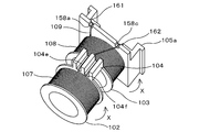
- the coil bobbin 1 has a first bobbin body 2 and a second bobbin arranged in series (arranged in the axial direction) with respect to the first bobbin body 2. It is composed of a main body 3 and a connecting portion 4 for connecting the first bobbin main body 2 and the second bobbin main body 3 in series, and a predetermined number of terminal fittings are built in one end portion in the axial direction thereof.
- the connector portion 5 is arranged.
- the coil bobbin 1 is made of a synthetic resin having an insulating property.
- the first bobbin main body 2 has a tubular body portion (first body portion) 2a around which a lead wire is wound and radially outer ends at both ends of the body portion 2a in the axial direction. It is composed of a pair of flat plate-shaped flange portions 2b and 2c formed so as to project toward.
- the first bobbin main body 2 is configured such that the flange portion 2c on one end side thereof is connected to the flange portion 3b on the one end side of the second bobbin main body 3 via the connecting portion 4. Has been done.
- the second bobbin main body 3 has a point that one of the pair of flat plate-shaped flange portions is integrally formed with the case main body 5a constituting the connector portion 5. Except for this, it has almost the same configuration as the first bobbin main body 2. That is, in FIG. 1, the second bobbin main body 3 has a tubular body portion (second body portion) 3a around which a conducting wire is wound, and one end of the body portion 3a in the axial direction outward in the radial direction. It is composed of a flat plate-shaped flange portion 3b formed so as to project toward the end and a case body 5a formed at the other end.
- the first body portion 2a and the second body portion 3a are both cylindrical, and insertion holes 2d and 3d are formed through the central portions thereof along the axial direction.
- the insertion holes 2d and 3d are for arranging an iron core (for example, a plunger) or the like inside the coil bobbin 1 when the coil bobbin 1 is configured as a coil device for a solenoid by winding a lead wire.
- the connecting portion 4 connects one end of the first bobbin body 2 (2c in FIG. 1) and one end of the second bobbin body 3 (3b in FIG. 1) in series. It is a thing.
- the connecting portion 4 is composed of a connecting portion main body 4a made of a plate-shaped body having a required size, and required intervals are provided at the central portion and both end portions of the radial outer surface thereof.
- the guide grooves 4e and 4f By forming the guide grooves 4e and 4f having a depth, the ribs 4b, 4c and 4d protruding outward in the radial direction and extending in the axial direction are formed.
- the guide grooves 4e and 4f are one end (winding start side) of a lead wire wound around the outer peripheral portion of the body portion of the bobbin main body (first bobbin main body 2 in FIG. 1) located at a position away from the connector portion 5.
- the ribs (ribs 4b and 4d) at both ends facilitate the winding of the lead wire, stabilize the position of the lead wire, and prevent damage to the lead wire due to an external influence.
- the central rib (rib 4c) can form an insulated state by isolating the two conductive wires arranged on the radial outer surface of the connecting portion 4, but it covers the conductive wires themselves. As a result, if an insulated state is formed, it is not always necessary to provide it.
- the connector portion 5 is provided at one end in the axial direction of the coil bobbin, and as shown in FIG. 2, is divided into two in the vertical direction in order to store each member and the like. In this embodiment, the connector portion 5 is divided into two. While pressing and fixing the case main body 5a in which the back side ends, the back surface and the upper portion of both side surfaces are opened, a predetermined number of terminal fittings 6 provided on the case main body 5a, and the terminal fittings 6 are pressed from above. It is composed of a case cover 5b that closes the opening of the case body 5a.
- the case body 5a constituting the connector portion 5 is integrally formed with the flange portion on the other end side of the second bobbin main body 3, but the case body 5a and the flange portion It is also possible to form them as separate bodies without forming them integrally.
- the case body 5a constituting the connector portion 5 is arranged on the other end side of the second bobbin body 3, but the arrangement position thereof is the coil bobbin.
- the bobbin for the coil can be selected according to the intended use.
- the case body 5a has a bottom surface 51a, a front wall 52a formed by standing upright from the front end edge of the bottom surface 51a, and the front wall 52a from the central portion of the bottom surface 51a. It is composed of a pair of side walls 54a and 54a erected on both end edges of a step portion 53a having a required height formed over the above.
- press-fitting grooves 55a and 55a are provided at the left and right ends of the stepped portion 53a so as to be cut out to a required depth according to the shapes of the connection terminals 61 and 62.
- an engaging protrusion for engaging with an engaging portion 61b (or 62b) formed on the front edge side of the connecting terminals 61, 62 is provided on the front end side in the press-fitting grooves 55a, 55a.
- the portions 56a and 56a are integrally attached.
- a press-fitting groove 55b formed by notching a required depth according to the shape of the terminal body 63a of the relay terminal 63 is provided at the center of the rear end of the bottom surface 51a.
- lateral openings 57a and 57a having a rectangular shape in a plan view are formed through the left and right ends of the front wall 52a of the case body 5a.
- the side openings 57a and 57a insert the male terminal into the connection terminals 61 and 62 composed of the female terminal when the male terminal provided in various devices is electrically contacted. Is for.
- the back side of the case body 5a is cut out to a predetermined depth from the outer peripheral side thereof, and the conducting wire is guided to the terminal metal fittings 6 (connection terminals 61, 62 and relay terminal 63).
- Guide wire guide portions 58a, 58b, 58c for this purpose are formed.
- the terminal fitting 6 is composed of a pair of connection terminals 61 and 62 and a relay terminal 63, both of which are made of a conductive metal.
- connection terminals 61 and 62 are all made of a conductive material, one end of which is electrically connected to a conducting wire, and the other end of which is an external terminal provided in an external connector on the other side (various devices) (FIG. It is configured to be electrically connected by contacting the contact portion (not shown).
- the connection terminals 61 and 62 are made of a material having springiness in addition to conductivity, but as terminals, at least conductive so that they can be electrically connected to the external terminals of the external connector. It suffices to be composed of a material having the above, and the composition is not particularly limited.
- connection terminals 61 and 62 constitute female terminals having symmetrical shapes, and each of them is punched by punching a single plate-like body into a predetermined shape. It is formed by bending a member in the plate thickness direction.
- the connection terminal 61 (or 62) is formed between a terminal body 61a (or 62a) held in the press-fitting groove 55a of the case body 5a and a longitudinal front end of the terminal body 61a (or 62a).
- the terminal body 61a Formed on the longitudinal trailing edge side of the terminal body 61a (or 62a), the joint portion 61b (or 62b), the elastic contact portion 61c (or 62c) formed at the tip of the engaging portion 61b (or 62b), and the terminal body 61a (or 62a). It is composed of a lead wire connecting portion 61d (or 62d).
- the engaging portion 61b (or 62b) is formed by bending the front end portion in the longitudinal direction of the terminal body 61a (or 62a), and the engaging portion 61b is engaged on the left side in FIG. 3A.
- the joint portion 62b is formed in a U shape with an opening on the right side).
- the engaging portion 61b (or 62b) engages with the engaging protrusion 56a of the case body 5a.
- the elastic contact portion 61c (or 62c) is formed by vertically bending the tip of the engaging portion 61b (or 62b) rearward so as to be parallel to the terminal body 61a (or 62a), and is an external connector. It is in contact with the external terminal of. Therefore, the elastic contact portion 61c (or 62c) can be elastically displaced in the plate thickness direction and elastically contacts the external terminal (male terminal) inserted from the side opening 57a which is the insertion port of the external terminal. It is configured to be possible.
- the lead wire connecting portion 61d (or 62d) is formed so as to project upward toward the trailing edge side in the longitudinal direction of the terminal body 61a (and 62a), and is for electrically connecting to the lead wire.
- terminal body 61a (and 62a) is formed with a wire guide portion 61e (or 62e) for guiding the wire by folding back the extension piece protruding from the rear edge.
- connection terminals 61 and 62 are press-fitted into the left and right ends of the stepped portion 53a of the case body 5a, the press-fitting grooves 55a and 55a are cut and formed at a predetermined depth according to the shape.
- the press-fitting grooves 55a and 55a are provided with engaging protrusions 56a and 56a that engage with the engaging portions 61b and 62b so as to project upward. Therefore, by press-fitting the terminal body 61a (or 62a) into the press-fitting groove 55a with the engaging portion 61b (or 62b) engaged with the engaging protrusion 56a, the connecting terminal 61 (or the connecting terminal 61 (or 62a) Or 62) is held by the case body 5a.
- the female terminal is selected as the connection terminal, but the terminal form can be selected according to the form of the external terminal provided in the device to be mounted.
- the relay terminal 63 has an inverted L-shape in a plan view by bending one end edge in the longitudinal direction of a punched member formed by punching a single plate-like body into a predetermined shape.
- the terminal body 63a is formed in the above direction, and the lead wire connecting portion 63b is formed so as to project upward toward the other end edge side.
- the terminal body 63a is held in the press-fitting groove 55b of the case body 5a.
- the lead wire connecting portion 63b is for electrically connecting to the lead wire, and in FIG. 4, one end of the lead wire wound around the body portion 2a of the first bobbin main body 2 and the second bobbin main body 3 One end of the lead wire wound around the bobbin 3a of the above is electrically connected.
- a press-fit groove 55b is provided according to the shape. Therefore, by press-fitting the terminal body 63a into the press-fitting groove 55b, the relay terminal 63 is held in the case body 5a.
- connection terminals 61 and 62 and the relay terminal 63 are attached to the case body 5a by press fitting into the press-fitting grooves 55a, 55a, 55b, but the terminal fittings are attached to the case body.
- the connection terminals 61 and 62 and the relay terminal 63 can be provided in the case body 5a by using a known method such as a method of burying the case body by integral molding.
- a through hole 59a is formed in the vertical direction in the central portion of the case body 5a. Further, a through hole 59b is formed in the central portion of the case cover 5b so as to correspond to the through hole 59a in the central portion of the case main body 5a, and as shown in FIG. 1, the case main body 5a and the said When the case covers 5b are combined, through holes that communicate with each other are formed in the vertical direction.
- the through hole is for arranging an iron core (for example, a plunger) or the like inside the coil bobbin 1 when the lead wire is wound to form a coil device for a solenoid.
- an electromagnetic coil 7 composed of a lead wire 9 is wound around an outer peripheral portion of a body portion 2a constituting the first bobbin main body 2, and the second bobbin main body 2 is formed.
- a coil device is formed by winding an electromagnetic coil 8 composed of a lead wire 10 around an outer peripheral portion of a bobbin 3a constituting the body 3.
- This coil device is, for example, electrically connected to one end of the lead wire 9 (winding start end) to one connection terminal 61 included in the connector portion 5, and further pulled out from the winding start end of the lead wire 9.
- the lead wire is pulled in in the order of the lead wire guide portion 58a and the guide groove 4e, and then with respect to the body portion 2a of the bobbin main body (first bobbin main body) 2 in which the connector portion 5 is not arranged, in the winding direction X.
- the guide groove 4f and the lead wire guide portion 58b are pulled in in this order, the other end (winding end end) is electrically connected to the central relay terminal 63, and then one end of another lead wire 10 (winding start end).
- one lead wire 109 is attached to the outer peripheral portion of the body portion 102a constituting the first bobbin body 102 and the body constituting the second bobbin body 103.
- a coil device can also be configured by winding around both outer peripheral portions of the portion 103a.
- the terminal fittings constituting the connector portion 105 can be composed of only a pair of connection terminals 161, 162, and one end (winding start end portion) of the lead wire 109 constituting each of the electromagnetic coils 107, 108. It is only necessary to electrically connect the other end (winding end end) to one connection terminal 161 and the other end (winding end end) to the other connection terminal 162, so that it can be manufactured more inexpensively and easily.
- the winding of the one lead wire 109 around the outer peripheral portions of both the body portion 102a and the body portion 103a can be performed manually or by using a predetermined winding device.
- the winding device is used, as shown in FIGS. 6 to 8, among the ribs protruding on the radial outer surface of the connecting portion, the rib 104d on the rear side in the winding direction X
- the height is set to at least a height such that the lead wire wound in the winding direction X is caught on the side wall of the rib 104d, and the height of each rib is set to the rib on the rear side in the winding direction X. It is preferable to set it so that it becomes lower from 104d toward the winding direction X (front side).
- the end portion on the connector portion 105 side is the connector portion. It is formed so as to be inclined downward toward 105 (inclined inward in the radial direction), and the end of the central rib 104c on the connector portion 105 side is deflected toward the front side in the winding direction X.
- the lead wire 109 when the lead wire 109 is pulled into the guide groove 104f, the lead wire 109 can be hooked on the inner side wall of the rib 104d, so that the lead wire 109 is arranged in the guide groove 104f. It becomes easy to do.
- the end portion of the central rib 104c opposite to the connector portion 105 is not inclined downward, and is on the front side of the winding direction X.
- the end of the rib 104b on the side opposite to the connector portion 105 is formed so as to be inclined downward toward the direction away from the connector portion 105, and the central rib 104c is formed so that the end on the side opposite to the connector portion 105 is in the winding direction. It is configured to be biased toward the rear side of X.
- the lead wire 109 when the lead wire 109 is pulled into the guide groove 104e, the lead wire 109 can be hooked on the side wall of the rib 104c on the rib 104b side, so that the lead wire 109 can be hooked into the guide groove 104e. It becomes easy to arrange in.
- the coil device is electrically connected to, for example, one end (winding start end) of the lead wire 109 to one connection terminal 161 provided by the connector portion 105, either manually or by using a predetermined winding device. Further, the lead wire drawn from the winding start end of the lead wire 109 is pulled into the lead wire guide portion 158a, and then with respect to the body portion 103a of the bobbin main body (second bobbin main body) 103 in which the connector portion 105 is arranged. Then, it is wound in the winding direction X, pulled into the guide groove 104f, and further wound around the body 102a of the bobbin body (first bobbin body) 102 in which the connector portion 105 is not arranged.
- the lead wire is first wound around the body 103a of the second bobbin body 103 in the winding direction X, and then the winding direction X is wound around the body 102a of the first bobbin body 102.
- the first bobbin body 102 may be wound around the body 102a first.
- the winding direction may be opposite to that of X.
- the coil device having such a configuration can be used as a coil device for various electronic devices, especially solenoids.
- the solenoid S includes a yoke 11 having a U-shaped cross section, a bobbin 101 for a coil built in the center of the yoke 2, and electromagnetic coils 107 and 108 wound around the bobbin 101 for a coil.
- a pair of magnets 13 and 14 mounted on the axial center of the coil bobbin 101, an iron core 15 arranged in the coil bobbin 101, and a yoke lid for closing the upper opening of the yoke 11. It is composed of twelve.
- the iron core 15 has a plunger 15a that is vertically swungly mounted in the coil bobbin 101, and the plunger 15a deviates from the inside of the yoke 11 at both ends thereof. It is composed of a pair of stoppers 15b and 15c arranged to prevent the above.
- the plunger 15a and the stoppers 15b and 15c are both cylindrical in shape made of iron or the like, and have an outer diameter substantially equal to the inner diameter of the body of the coil bobbin 101 (the outer diameter of the through hole).
- the pair of stoppers 15b and 15c are configured such that one (15b in FIG. 10) is fixed to the yoke lid 12 and the other (15c in FIG. 10) is fixed to the yoke 11.
- the solenoid S having such a configuration is connected to the power sources of various devices, and when not energized, the plunger 15a is described by the pair of magnets 13 and 14 arranged at the central portion in the axial direction of the connecting body 104.
- the plunger 15a is stationary. Swings in the direction of the energized solenoid coil.
- the coil bobbin according to the present invention can be used in a wide range of fields because it can be used to inexpensively manufacture a coil device that is small and can be easily attached to various devices without providing a lead wire. Can be used.
Abstract
[Problem] The purpose of the present invention is to provide a coil device that is small in size, can be easily attached to various devices, and can be easily and inexpensively manufactured without providing a lead wire, a method of manufacturing the same, and a coil bobbin used therein. [Solution] The coil device 1 of the present invention, which is for winding a conductive wire constituting an electromagnetic coil, comprises: a first bobbin body 2; a second bobbin body 3 that is disposed in series to the first bobbin body 2, and a connection part 4 that connects the first bobbin body 2 and the second bobbin body 3 in series to each other, and a connector part 5 in which a predetermined number of terminal fittings 6 are embedded is disposed at one end portion of the coil bobbin 1 in an axial direction. Therefore, since a relatively large space for providing the lead wire as in the related art is not required, the coil device is thus small, and as a result, can be manufactured at low cost.
Description
この発明は、各種電子機器、特にソレノイドに使用可能なコイル装置及びその製造方法、並びにこれらに用いられるコイル用ボビンに関するものである。
より詳しくは、リード線を設けることなく、小型で各種機器に簡単に取付けることができ、且つ簡単に製造することができるコイル装置とその製造方法、並びにこれらに用いられるコイル用ボビンに関するものである。
The present invention relates to various electronic devices, particularly coil devices that can be used for solenoids, methods for manufacturing the same, and bobbins for coils used for these.
More specifically, the present invention relates to a coil device that is small in size, can be easily attached to various devices, and can be easily manufactured without providing a lead wire, a manufacturing method thereof, and a bobbin for a coil used for these. ..
従来、各種電子機器、例えば、ソレノイドに使用されるコイル装置は、そのコイル用ボビンの外周部に巻回されている電磁コイルが通電されると、このコイルのまわりに磁界が発生するよう構成されている。
かかるソレノイドの一例が、特許文献1に開示されている。 Conventionally, various electronic devices, for example, coil devices used for solenoids are configured to generate a magnetic field around the coil when an electromagnetic coil wound around the outer periphery of the coil bobbin is energized. ing.
An example of such a solenoid is disclosed in Patent Document 1.
特開2013-222806号公報(特許文献1)には、ヨーク内に配置される電磁コイルを有するボビンと、前記ボビン内に配置される磁性芯と、基端部に係着されるスプリング部材によって前記ヨーク上に揺動自在に配置されるフラッパを主構成要素とする型ソレノイドであって、
少なくとも、前記ボビンと前記ボビン上に揺動自在に設けられるフラッパとが、プラスチック材料で形成され、前記ボビンとフラッパが、断面円弧状のスプリング部材で一体的に連結されていることを特徴とするフラッパ型ソレノイドが提案されている。 According to Japanese Patent Application Laid-Open No. 2013-222806 (Patent Document 1), a bobbin having an electromagnetic coil arranged in a yoke, a magnetic core arranged in the bobbin, and a spring member engaged to a proximal end portion are used. A type solenoid whose main component is a flapper that is swingably arranged on the yoke.
At least, the bobbin and the flapper provided swingably on the bobbin are formed of a plastic material, and the bobbin and the flapper are integrally connected by a spring member having an arcuate cross section. A flapper type solenoid has been proposed.
このフラッパ型ソレノイドは、リード線を介してコイルが通電されると、コイルのまわりに磁界が発生するよう構成されたものである。
This flapper type solenoid is configured to generate a magnetic field around the coil when the coil is energized via a lead wire.
This flapper type solenoid is configured to generate a magnetic field around the coil when the coil is energized via a lead wire.
前記特許文献1に開示されているフラッパ型ソレノイドなど、従来のソレノイドに使用されているコイル装置は、そのコイル用ボビンに巻回されている巻線(導線)に接続された端子又はリード線を介して、相手(各種機器)側と電気的に接続するように構成される。
したがって、従来のソレノイドでは、オス型端子を具備するコネクタ部やリード線を設けるためのスペースを必要とする、という問題があった。 A coil device used in a conventional solenoid, such as the flapper type solenoid disclosed in Patent Document 1, has a terminal or a lead wire connected to a winding (lead wire) wound around the bobbin for the coil. It is configured to be electrically connected to the other party (various devices) via the device.
Therefore, the conventional solenoid has a problem that a space for providing a connector portion having a male terminal and a lead wire is required.
さらに、上記従来のソレノイドでは、ソレノイド本体を各種機器に取付ける工程の他に、前記ソレノイド(詳しくは、そのコイル装置)と前記機器とを、コネクタ部又はリード線を介して電気的に接続する工程が必要とされるため取付けが煩雑である、という問題もあった。
Further, in the conventional solenoid, in addition to the step of attaching the solenoid body to various devices, the step of electrically connecting the solenoid (specifically, its coil device) and the device via a connector portion or a lead wire. There is also a problem that the installation is complicated because the above is required.
この発明はかかる現状に鑑み、リード線を設けることなく、小型で、各種機器に簡単に取付けることができ、簡単且つ安価に製造することができるコイル装置とその製造方法、並びにこれらに用いられるコイル用ボビンを提供せんとするものである。
In view of the current situation, the present invention is a coil device that is small in size, can be easily attached to various devices, and can be easily and inexpensively manufactured without providing a lead wire, a manufacturing method thereof, and a coil used for these. It is intended to provide a bobbin for use.
In view of the current situation, the present invention is a coil device that is small in size, can be easily attached to various devices, and can be easily and inexpensively manufactured without providing a lead wire, a manufacturing method thereof, and a coil used for these. It is intended to provide a bobbin for use.
前記目的を達成するため、この発明にかかる請求項1に記載の発明は、
電磁コイルを構成する導線を巻回するためのコイル用ボビンであって、
第1のボビン本体と、前記第1のボビン本体に対して直列に配置される第2のボビン本体と、前記第1のボビン本体と第2のボビン本体とを直列に連結する連結部で構成され、
前記コイル用ボビンの軸方向一端部には、所定の数の端子金具を内蔵するコネクタ部が配設されていること
を特徴とするコイル用ボビンである。 In order to achieve the above object, the invention according to claim 1 according to the present invention
A coil bobbin for winding the conductors that make up the electromagnetic coil.
It is composed of a first bobbin body, a second bobbin body arranged in series with respect to the first bobbin body, and a connecting portion for connecting the first bobbin body and the second bobbin body in series. Being done
The coil bobbin is characterized in that a connector portion incorporating a predetermined number of terminal fittings is provided at one end in the axial direction of the coil bobbin.
この発明の請求項2に記載の発明は、
請求項1に記載のコイル用ボビンにおいて、
前記第1のボビン本体及び前記第2のボビン本体は、いずれも
導線が巻回される筒状の胴部とその両端に対向して配置される一対のフランジ部を備えるよう構成され、
前記連結部は、
前記第1のボビン本体の一端側のフランジ部と前記第2のボビン本体の一端側のフランジ部とを直列に連結するよう構成され、
前記コネクタ部は、
前記第1のボビン本体の他端側又は前記第2のボビン本体の他端側に配設されていること
を特徴とするものである。 The invention according toclaim 2 of the present invention
In the coil bobbin according to claim 1,
Both the first bobbin body and the second bobbin body are configured to include a tubular body around which a lead wire is wound and a pair of flanges arranged to face each other at both ends thereof.
The connecting part
The flange portion on one end side of the first bobbin body and the flange portion on one end side of the second bobbin body are configured to be connected in series.
The connector part
It is characterized in that it is disposed on the other end side of the first bobbin main body or the other end side of the second bobbin main body.
請求項1に記載のコイル用ボビンにおいて、
前記第1のボビン本体及び前記第2のボビン本体は、いずれも
導線が巻回される筒状の胴部とその両端に対向して配置される一対のフランジ部を備えるよう構成され、
前記連結部は、
前記第1のボビン本体の一端側のフランジ部と前記第2のボビン本体の一端側のフランジ部とを直列に連結するよう構成され、
前記コネクタ部は、
前記第1のボビン本体の他端側又は前記第2のボビン本体の他端側に配設されていること
を特徴とするものである。 The invention according to
In the coil bobbin according to claim 1,
Both the first bobbin body and the second bobbin body are configured to include a tubular body around which a lead wire is wound and a pair of flanges arranged to face each other at both ends thereof.
The connecting part
The flange portion on one end side of the first bobbin body and the flange portion on one end side of the second bobbin body are configured to be connected in series.
The connector part
It is characterized in that it is disposed on the other end side of the first bobbin main body or the other end side of the second bobbin main body.
この発明の請求項3に記載の発明は、
請求項2に記載のコイル用ボビンにおいて、
前記第1のボビン本体の他端側のフランジ部又は前記第2のボビン本体の他端側のフランジ部は、
前記コネクタ部と一体に形成されていること
を特徴とするものである。 The invention according toclaim 3 of the present invention
In the coil bobbin according toclaim 2.
The flange portion on the other end side of the first bobbin body or the flange portion on the other end side of the second bobbin body is
It is characterized in that it is integrally formed with the connector portion.
請求項2に記載のコイル用ボビンにおいて、
前記第1のボビン本体の他端側のフランジ部又は前記第2のボビン本体の他端側のフランジ部は、
前記コネクタ部と一体に形成されていること
を特徴とするものである。 The invention according to
In the coil bobbin according to
The flange portion on the other end side of the first bobbin body or the flange portion on the other end side of the second bobbin body is
It is characterized in that it is integrally formed with the connector portion.
この発明の請求項4に記載の発明は、
請求項1~3のいずれかに記載のコイル用ボビンにおいて、
前記連結部は、
板状体で構成され、
その径方向外面の中央部及び両端部には、所定の間隔を存して所要の深さの溝を形成することによって、径方向外方に突出し且つ軸方向に延びる3つのリブが形成されていること
を特徴とするものである。 The invention according toclaim 4 of the present invention
In the coil bobbin according to any one of claims 1 to 3.
The connecting part
Consists of plate-like bodies
At the center and both ends of the radial outer surface, three ribs protruding outward in the radial direction and extending in the axial direction are formed by forming grooves of a required depth at predetermined intervals. It is characterized by being present.
請求項1~3のいずれかに記載のコイル用ボビンにおいて、
前記連結部は、
板状体で構成され、
その径方向外面の中央部及び両端部には、所定の間隔を存して所要の深さの溝を形成することによって、径方向外方に突出し且つ軸方向に延びる3つのリブが形成されていること
を特徴とするものである。 The invention according to
In the coil bobbin according to any one of claims 1 to 3.
The connecting part
Consists of plate-like bodies
At the center and both ends of the radial outer surface, three ribs protruding outward in the radial direction and extending in the axial direction are formed by forming grooves of a required depth at predetermined intervals. It is characterized by being present.
この発明の請求項5に記載の発明は、
請求項4に記載のコイル用ボビンにおいて、
前記端子金具は、
一対の端子金具で構成され、
前記リブは、
その高さが、巻回方向の後方側のリブから巻回方向に向かうに従って低くなるよう形成され、
中央のリブ及び巻回方向の前方側のリブは、さらに、
コネクタ部側の端部が径方向内側に向かって傾斜するよう構成され、
前記中央のリブは、さらに、
コネクタ部側の端部が巻回方向の前方側に向かって偏倚するよう構成されていること
を特徴とするものである。 The invention according toclaim 5 of the present invention
In the coil bobbin according toclaim 4,
The terminal fitting
Consists of a pair of terminal fittings
The rib
The height is formed so as to decrease from the rib on the rear side in the winding direction toward the winding direction.
The central rib and the front rib in the winding direction further
The end on the connector side is configured to incline inward in the radial direction.
The central rib further
It is characterized in that the end portion on the connector portion side is configured to be biased toward the front side in the winding direction.
請求項4に記載のコイル用ボビンにおいて、
前記端子金具は、
一対の端子金具で構成され、
前記リブは、
その高さが、巻回方向の後方側のリブから巻回方向に向かうに従って低くなるよう形成され、
中央のリブ及び巻回方向の前方側のリブは、さらに、
コネクタ部側の端部が径方向内側に向かって傾斜するよう構成され、
前記中央のリブは、さらに、
コネクタ部側の端部が巻回方向の前方側に向かって偏倚するよう構成されていること
を特徴とするものである。 The invention according to
In the coil bobbin according to
The terminal fitting
Consists of a pair of terminal fittings
The rib
The height is formed so as to decrease from the rib on the rear side in the winding direction toward the winding direction.
The central rib and the front rib in the winding direction further
The end on the connector side is configured to incline inward in the radial direction.
The central rib further
It is characterized in that the end portion on the connector portion side is configured to be biased toward the front side in the winding direction.
この発明の請求項6に記載の発明は、
請求項1~5のいずれかに記載のコイル用ボビンと、
前記第1のボビン本体の胴部の外周部に形成された第1の電磁コイルと、
前記第2のボビン本体の胴部の外周部に形成された第2の電磁コイルで構成されること
を特徴とするコイル装置である。 The invention according toclaim 6 of the present invention
The coil bobbin according to any one of claims 1 to 5.
The first electromagnetic coil formed on the outer peripheral portion of the body of the first bobbin body and
The coil device is characterized by being composed of a second electromagnetic coil formed on the outer peripheral portion of the body portion of the second bobbin main body.
請求項1~5のいずれかに記載のコイル用ボビンと、
前記第1のボビン本体の胴部の外周部に形成された第1の電磁コイルと、
前記第2のボビン本体の胴部の外周部に形成された第2の電磁コイルで構成されること
を特徴とするコイル装置である。 The invention according to
The coil bobbin according to any one of claims 1 to 5.
The first electromagnetic coil formed on the outer peripheral portion of the body of the first bobbin body and
The coil device is characterized by being composed of a second electromagnetic coil formed on the outer peripheral portion of the body portion of the second bobbin main body.
この発明の請求項7に記載の発明は、
請求項6に記載のコイル装置において、
前記コネクタ部は、
前記第1の電磁コイルを構成する導線の一端と電気的に接続する第1の端子金具と、前記第1の電磁コイルを構成する導線の他端及び前記第2の電磁コイルを構成する導線の一端と電気的に接続する第2の端子金具と、前記第2の電磁コイルを構成する導線の他端と電気的に接続する第3の端子金具を具備すること
を特徴とするものである。 The invention according to claim 7 of the present invention
In the coil device according toclaim 6,
The connector part
A first terminal fitting that is electrically connected to one end of a lead wire that constitutes the first electromagnetic coil, the other end of the lead wire that constitutes the first electromagnetic coil, and a lead wire that constitutes the second electromagnetic coil. It is characterized by including a second terminal fitting that is electrically connected to one end and a third terminal fitting that is electrically connected to the other end of a lead wire constituting the second electromagnetic coil.
請求項6に記載のコイル装置において、
前記コネクタ部は、
前記第1の電磁コイルを構成する導線の一端と電気的に接続する第1の端子金具と、前記第1の電磁コイルを構成する導線の他端及び前記第2の電磁コイルを構成する導線の一端と電気的に接続する第2の端子金具と、前記第2の電磁コイルを構成する導線の他端と電気的に接続する第3の端子金具を具備すること
を特徴とするものである。 The invention according to claim 7 of the present invention
In the coil device according to
The connector part
A first terminal fitting that is electrically connected to one end of a lead wire that constitutes the first electromagnetic coil, the other end of the lead wire that constitutes the first electromagnetic coil, and a lead wire that constitutes the second electromagnetic coil. It is characterized by including a second terminal fitting that is electrically connected to one end and a third terminal fitting that is electrically connected to the other end of a lead wire constituting the second electromagnetic coil.
この発明の請求項8に記載の発明は、
請求項6に記載のコイル装置において、
前記第1の電磁コイルと第2の電磁コイルは、
1本の導線で連続して形成され、
前記端子金具は、
一対の端子金具で構成され、
前記導線は、
その一端が一方の端子金具と、他端が他方の端子金具と、それぞれ電気的に接続されていること
を特徴とするものである。 The invention according toclaim 8 of the present invention
In the coil device according toclaim 6,
The first electromagnetic coil and the second electromagnetic coil are
Formed continuously by one lead wire,
The terminal fitting
Consists of a pair of terminal fittings
The lead wire is
One end thereof is electrically connected to one terminal fitting and the other end is electrically connected to the other terminal fitting.
請求項6に記載のコイル装置において、
前記第1の電磁コイルと第2の電磁コイルは、
1本の導線で連続して形成され、
前記端子金具は、
一対の端子金具で構成され、
前記導線は、
その一端が一方の端子金具と、他端が他方の端子金具と、それぞれ電気的に接続されていること
を特徴とするものである。 The invention according to
In the coil device according to
The first electromagnetic coil and the second electromagnetic coil are
Formed continuously by one lead wire,
The terminal fitting
Consists of a pair of terminal fittings
The lead wire is
One end thereof is electrically connected to one terminal fitting and the other end is electrically connected to the other terminal fitting.
この発明の請求項9に記載の発明は、
請求項5に記載のコイル用ボビンのコネクタ部内に配設されている一対の端子金具のうち、一方の端子金具を、導線の巻き始め端部と電気的に接続する工程と、
前記導線の巻き始め端部から引き出された導線を第2のボビン本体の胴部の外周部に巻回して第2の電磁コイルを形成し、ついで巻回方向の前方側のリブと中央のリブの間の溝に通し、さらに、第1のボビン本体の胴部の外周部に巻回して第1の電磁コイルを形成する工程と、
前記導線の巻き終わり端部を、中央のリブと巻回方向の後方側のリブの間の溝に通して、ついで他方の端子金具と電気的に接続する工程
を含むこと
を特徴とするコイル装置の製造方法である。 The invention according to claim 9 of the present invention
A step of electrically connecting one of the pair of terminal fittings arranged in the connector portion of the coil bobbin according toclaim 5 to the winding start end portion of the conducting wire.
The lead wire drawn from the winding start end of the lead wire is wound around the outer peripheral portion of the body of the second bobbin body to form a second electromagnetic coil, and then the front rib and the central rib in the winding direction are formed. A step of forming a first electromagnetic coil by passing it through a groove between the two and winding it around the outer peripheral portion of the body of the first bobbin body.
A coil device comprising a step of passing the winding end end of the lead wire through a groove between a central rib and a rib on the rear side in the winding direction, and then electrically connecting to the other terminal fitting. It is a manufacturing method of.
請求項5に記載のコイル用ボビンのコネクタ部内に配設されている一対の端子金具のうち、一方の端子金具を、導線の巻き始め端部と電気的に接続する工程と、
前記導線の巻き始め端部から引き出された導線を第2のボビン本体の胴部の外周部に巻回して第2の電磁コイルを形成し、ついで巻回方向の前方側のリブと中央のリブの間の溝に通し、さらに、第1のボビン本体の胴部の外周部に巻回して第1の電磁コイルを形成する工程と、
前記導線の巻き終わり端部を、中央のリブと巻回方向の後方側のリブの間の溝に通して、ついで他方の端子金具と電気的に接続する工程
を含むこと
を特徴とするコイル装置の製造方法である。 The invention according to claim 9 of the present invention
A step of electrically connecting one of the pair of terminal fittings arranged in the connector portion of the coil bobbin according to
The lead wire drawn from the winding start end of the lead wire is wound around the outer peripheral portion of the body of the second bobbin body to form a second electromagnetic coil, and then the front rib and the central rib in the winding direction are formed. A step of forming a first electromagnetic coil by passing it through a groove between the two and winding it around the outer peripheral portion of the body of the first bobbin body.
A coil device comprising a step of passing the winding end end of the lead wire through a groove between a central rib and a rib on the rear side in the winding direction, and then electrically connecting to the other terminal fitting. It is a manufacturing method of.
この発明の請求項10に記載の発明は、
請求項6~8のいずれかに記載のコイル装置、或いは請求項9に記載の製造方法によって得られるコイル装置を備えること
を特徴とするソレノイドである。
The invention according to claim 10 of the present invention
A solenoid comprising the coil device according to any one ofclaims 6 to 8 or the coil device obtained by the manufacturing method according to claim 9.
請求項6~8のいずれかに記載のコイル装置、或いは請求項9に記載の製造方法によって得られるコイル装置を備えること
を特徴とするソレノイドである。
The invention according to claim 10 of the present invention
A solenoid comprising the coil device according to any one of
この発明のコイル用ボビンは、電磁コイルを構成する導線を巻回するためのもので、第1のボビン本体と、前記第1のボビン本体に対して直列に配置される第2のボビン本体と、前記第1のボビン本体と第2のボビン本体とを直列に連結する連結部で構成され、前記コイル用ボビンの軸方向一端部に、所定の数の端子金具を内蔵するコネクタ部を配設したものである。
したがって、このコイル用ボビンは、その軸方向一端部に、所定の数の端子金具を内蔵するコネクタ部を配設する構成としたので、従前のような各種機器への電気的な接続のためのリード線を必要とせず、小型で、各種機器に簡単に取付けることができ、簡単且つ安価に製造することができるものである。 The bobbin for a coil of the present invention is for winding a lead wire constituting an electromagnetic coil, and has a first bobbin body and a second bobbin body arranged in series with the first bobbin body. , The first bobbin main body and the second bobbin main body are connected in series, and a connector portion containing a predetermined number of terminal fittings is arranged at one end in the axial direction of the coil bobbin. It was done.
Therefore, this coil bobbin has a configuration in which a connector portion containing a predetermined number of terminal fittings is arranged at one end in the axial direction, so that the bobbin can be electrically connected to various devices as in the past. It does not require a lead wire, is small in size, can be easily attached to various devices, and can be manufactured easily and inexpensively.
前記コイル用ボビンにおいて、前記第1のボビン本体及び前記第2のボビン本体を、導線が巻回される筒状の胴部とその両端に対向して配置される一対のフランジ部を備えるよう構成すると共に、前記連結部を、前記第1のボビン本体の一端側のフランジ部と前記第2のボビン本体の一端側のフランジ部とを直列に連結するよう構成し、前記コネクタ部を、前記第1のボビン本体の他端側のフランジ部又は前記第2のボビン本体の他端側のフランジ部と一体に形成することができる。
このような構成によって、コイル用ボビンの更なる小型化が可能となる。 In the coil bobbin, the first bobbin main body and the second bobbin main body are configured to include a tubular body around which a lead wire is wound and a pair of flanges arranged to face each other at both ends thereof. At the same time, the connecting portion is configured to connect the flange portion on one end side of the first bobbin body and the flange portion on one end side of the second bobbin body in series, and the connector portion is connected to the first bobbin body. It can be integrally formed with the flange portion on the other end side of the bobbin body 1 or the flange portion on the other end side of the second bobbin body.
With such a configuration, the coil bobbin can be further miniaturized.
さらに、前記コイル用ボビンにおいて、前記端子金具を、一対の端子金具で構成することができる。
このような構成によって、前記第1のボビン本体の胴部及び前記第2のボビン本体の胴部の両方を1本の導線で連続して巻回して電磁コイルを形成することができるので、より安価なコイル装置の製造が可能となる。 Further, in the coil bobbin, the terminal fitting can be composed of a pair of terminal fittings.
With such a configuration, both the body of the first bobbin body and the body of the second bobbin body can be continuously wound by one lead wire to form an electromagnetic coil. It is possible to manufacture an inexpensive coil device.
さらにまた、前記コイル用ボビンにおいて、前記連結部を、板状体で構成すると共に、その径方向外面の中央部及び両端部に、所定の間隔を存して所要の深さの溝を形成することによって、径方向外方に突出し且つ軸方向に延びる3つのリブを形成した構成とすることができる。
その際、前記リブを、その高さが、巻回方向の後方側のリブから巻回方向に向かうに従って低くなるよう形成すると共に、中央のリブ及び巻回方向の前方側のリブを、コネクタ部側の端部が径方向内側に向かって傾斜し、前記中央のリブを、コネクタ部側の端部が巻回方向の前方側に向かって偏倚するよう構成することができる。
このような構成によって、前記第1のボビン本体の胴部及び前記第2のボビン本体の胴部の両方に、1本の導線を、所定の巻回装置を利用して、自動で連続して巻回することが可能となる。 Furthermore, in the coil bobbin, the connecting portion is formed of a plate-like body, and grooves having a required depth are formed at the central portion and both end portions of the radial outer surface thereof at predetermined intervals. This makes it possible to form three ribs that project outward in the radial direction and extend in the axial direction.
At that time, the rib is formed so that the height thereof decreases from the rib on the rear side in the winding direction toward the winding direction, and the central rib and the rib on the front side in the winding direction are connected to the connector portion. The end on the side can be inclined inward in the radial direction, and the central rib can be configured so that the end on the connector side is biased toward the front in the winding direction.
With such a configuration, one lead wire is automatically and continuously connected to both the body of the first bobbin body and the body of the second bobbin body by using a predetermined winding device. It becomes possible to wind it.
この発明のコイル装置は、前記コイル用ボビンと、前記第1のボビン本体の胴部の外周部に形成された第1の電磁コイルと、前記第2のボビン本体の胴部の外周部に形成された第2の電磁コイルで構成したものであるので、従前のような各種機器への電気的な接続のためのリード線を必要とせず、小型で、各種機器に簡単に取付けることができ、簡単且つ安価に製造することができるものである。
The coil device of the present invention is formed on the bobbin for the coil, the first electromagnetic coil formed on the outer peripheral portion of the bobbin body of the first bobbin body, and the outer peripheral portion of the bobbin body of the second bobbin body. Since it is composed of a second electromagnetic coil, it does not require a lead wire for electrical connection to various devices as before, and it is compact and can be easily attached to various devices. It can be manufactured easily and inexpensively.
前記コイル装置において、前記端子金具を、一対の端子金具で構成した場合には、前記一対の端子金具のうち、一方の端子金具を、導線の巻き始め端部と電気的に接続、固定する工程と、前記導線の巻き始め端部から引き出された導線を第2のボビン本体の同部の外周部に巻回して第2の電磁コイルを形成し、ついで巻回方向の前方側のリブと中央のリブの間の溝に通し、さらに、第1のボビン本体の胴部の外周部に巻回して第1の電磁コイルを形成する工程と、前記導線の巻き終わり端部を、中央のリブと巻回方向の後方側のリブの間の溝に通して、ついで他方の端子金具と電気的に接続、固定する工程を含む方法によって、その製造を行うことができるので、極めて簡便である。
In the coil device, when the terminal fitting is composed of a pair of terminal fittings, a step of electrically connecting and fixing one of the pair of terminal fittings to the winding start end of the conducting wire. Then, the lead wire drawn from the winding start end of the lead wire is wound around the outer peripheral portion of the same portion of the second bobbin body to form a second electromagnetic coil, and then the rib and the center on the front side in the winding direction. The step of forming the first electromagnetic coil by passing it through the groove between the ribs and further winding it around the outer peripheral portion of the body of the first bobbin body, and the winding end end of the lead wire with the central rib. It is extremely convenient because it can be manufactured by a method including a step of passing it through a groove between ribs on the rear side in the winding direction and then electrically connecting and fixing it to the other terminal fitting.
この発明のコイル装置は、各種機器に利用することができるもので、このコイル装置をソレノイドに適用した場合には、リード線を設ける必要がないので、ソレノイドの小型化が実現される。
The coil device of the present invention can be used in various devices, and when this coil device is applied to a solenoid, it is not necessary to provide a lead wire, so that the solenoid can be miniaturized.
The coil device of the present invention can be used in various devices, and when this coil device is applied to a solenoid, it is not necessary to provide a lead wire, so that the solenoid can be miniaturized.
以下、この発明にかかるコイル用ボビンと、これを備えるコイル装置及びその製造方法について、添付の図面に基づいて具体的に説明する。
なお、この発明は開示された実施例にのみ限定されるものではなく、その要旨を変更しない範囲内において種々改良することができるものである。 Hereinafter, the coil bobbin according to the present invention, the coil device provided with the bobbin, and the manufacturing method thereof will be specifically described with reference to the accompanying drawings.
It should be noted that the present invention is not limited to the disclosed examples, and various improvements can be made without changing the gist thereof.
この発明にかかるコイル用ボビン1は、図1に示すように、第1のボビン本体2と、前記第1のボビン本体2に対して直列に(軸方向に並べて)配置される第2のボビン本体3と、前記第1のボビン本体2及び第2のボビン本体3を直列に連結する連結部4で構成されるもので、その軸方向一端部には、所定の数の端子金具を内蔵するコネクタ部5が配設されたものである。
なお、この実施例において、前記コイル用ボビン1は、絶縁性を有する合成樹脂で構成されている。 As shown in FIG. 1, the coil bobbin 1 according to the present invention has afirst bobbin body 2 and a second bobbin arranged in series (arranged in the axial direction) with respect to the first bobbin body 2. It is composed of a main body 3 and a connecting portion 4 for connecting the first bobbin main body 2 and the second bobbin main body 3 in series, and a predetermined number of terminal fittings are built in one end portion in the axial direction thereof. The connector portion 5 is arranged.
In this embodiment, the coil bobbin 1 is made of a synthetic resin having an insulating property.
なお、この実施例において、前記コイル用ボビン1は、絶縁性を有する合成樹脂で構成されている。 As shown in FIG. 1, the coil bobbin 1 according to the present invention has a
In this embodiment, the coil bobbin 1 is made of a synthetic resin having an insulating property.
前記第1のボビン本体2は、図1に示すように、導線が巻回される筒状の胴部(第1の胴部)2aと、前記胴部2aの軸方向の両端に径方向外側に向かって突出形成された一対の平板状のフランジ部2b,2cで構成されている。
この実施例において、前記第1のボビン本体2は、その一端側のフランジ部2cが、連結部4を介して前記第2のボビン本体3の一端側のフランジ部3bと接続されるように構成されている。 As shown in FIG. 1, the first bobbinmain body 2 has a tubular body portion (first body portion) 2a around which a lead wire is wound and radially outer ends at both ends of the body portion 2a in the axial direction. It is composed of a pair of flat plate-shaped flange portions 2b and 2c formed so as to project toward.
In this embodiment, the first bobbinmain body 2 is configured such that the flange portion 2c on one end side thereof is connected to the flange portion 3b on the one end side of the second bobbin main body 3 via the connecting portion 4. Has been done.
この実施例において、前記第1のボビン本体2は、その一端側のフランジ部2cが、連結部4を介して前記第2のボビン本体3の一端側のフランジ部3bと接続されるように構成されている。 As shown in FIG. 1, the first bobbin
In this embodiment, the first bobbin
前記第2のボビン本体3は、図1に示すように、一対の平板状のフランジ部のうち、一方のフランジ部が、コネクタ部5を構成するケース本体5aと一体に形成されている点を除き、前記第1のボビン本体2とほぼ同様の構成を有している。
すなわち、図1において、前記第2のボビン本体3は、導線が巻回される筒状の胴部(第2の胴部)3aと、前記胴部3aの軸方向の一端に径方向外側に向かって突出形成された平板状のフランジ部3bと、他端に形成されたケース本体5aで構成されている。 As shown in FIG. 1, the second bobbinmain body 3 has a point that one of the pair of flat plate-shaped flange portions is integrally formed with the case main body 5a constituting the connector portion 5. Except for this, it has almost the same configuration as the first bobbin main body 2.
That is, in FIG. 1, the second bobbinmain body 3 has a tubular body portion (second body portion) 3a around which a conducting wire is wound, and one end of the body portion 3a in the axial direction outward in the radial direction. It is composed of a flat plate-shaped flange portion 3b formed so as to project toward the end and a case body 5a formed at the other end.
すなわち、図1において、前記第2のボビン本体3は、導線が巻回される筒状の胴部(第2の胴部)3aと、前記胴部3aの軸方向の一端に径方向外側に向かって突出形成された平板状のフランジ部3bと、他端に形成されたケース本体5aで構成されている。 As shown in FIG. 1, the second bobbin
That is, in FIG. 1, the second bobbin
図1及び2において、前記第1の胴部2a及び前記第2の胴部3aは、いずれも円筒状であり、それぞれの中央部に、軸方向に沿って貫通形成された挿通孔2d,3dを備える。
前記挿通孔2d,3dは、前記コイル用ボビン1を、導線を巻回してソレノイド用のコイル装置として構成する場合において、その内部に鉄芯(例えばプランジャ)などを配置するためのものである。 In FIGS. 1 and 2, thefirst body portion 2a and the second body portion 3a are both cylindrical, and insertion holes 2d and 3d are formed through the central portions thereof along the axial direction. To be equipped.
The insertion holes 2d and 3d are for arranging an iron core (for example, a plunger) or the like inside the coil bobbin 1 when the coil bobbin 1 is configured as a coil device for a solenoid by winding a lead wire.
前記挿通孔2d,3dは、前記コイル用ボビン1を、導線を巻回してソレノイド用のコイル装置として構成する場合において、その内部に鉄芯(例えばプランジャ)などを配置するためのものである。 In FIGS. 1 and 2, the
The insertion holes 2d and 3d are for arranging an iron core (for example, a plunger) or the like inside the coil bobbin 1 when the coil bobbin 1 is configured as a coil device for a solenoid by winding a lead wire.
前記連結部4は、図1に示すように、前記第1のボビン本体2の一端部(図1において2c)と第2のボビン本体3の一端部(図1において3b)を直列に連結するものである。
As shown in FIG. 1, the connecting portion 4 connects one end of the first bobbin body 2 (2c in FIG. 1) and one end of the second bobbin body 3 (3b in FIG. 1) in series. It is a thing.
図1において、前記連結部4は、所要の大きさの板状体からなる連結部本体4aで構成され、その径方向外面の中央部及び両端部には、所定の間隔を存して所要の深さのガイド溝4e,4fを形成することによって、径方向外方に突出し且つ軸方向に延びるリブ4b,4c,4dが、形成されている。
前記ガイド溝4e,4fは、前記コネクタ部5から離れた位置にあるボビン本体(図1において第1のボビン本体2)の胴部の外周部に巻回される導線の一端(巻き始め側)と他端(巻き終わり側)のそれぞれを、端子金具6に案内するための導線案内部を構成するものである。
したがって、両端のリブ(リブ4b,4d)によって、導線の巻回が容易になるとともに、導線の位置を安定させることができ、外部からの影響による導線の破損を防止することができる。
なお、中央のリブ(リブ4c)は、連結部4の径方向外面に配される2本の導線同士を隔離して絶縁状態を構成することができるものであるが、導線自体を被覆等することにより絶縁した状態が形成されていれば、必ずしも設けることを要しないものである。 In FIG. 1, the connectingportion 4 is composed of a connecting portion main body 4a made of a plate-shaped body having a required size, and required intervals are provided at the central portion and both end portions of the radial outer surface thereof. By forming the guide grooves 4e and 4f having a depth, the ribs 4b, 4c and 4d protruding outward in the radial direction and extending in the axial direction are formed.
The guide grooves 4e and 4f are one end (winding start side) of a lead wire wound around the outer peripheral portion of the body portion of the bobbin main body (first bobbin main body 2 in FIG. 1) located at a position away from the connector portion 5. It constitutes a lead wire guide portion for guiding each of the other end (winding end side) to the terminal fitting 6.
Therefore, the ribs ( ribs 4b and 4d) at both ends facilitate the winding of the lead wire, stabilize the position of the lead wire, and prevent damage to the lead wire due to an external influence.
The central rib (rib 4c) can form an insulated state by isolating the two conductive wires arranged on the radial outer surface of the connecting portion 4, but it covers the conductive wires themselves. As a result, if an insulated state is formed, it is not always necessary to provide it.
前記ガイド溝4e,4fは、前記コネクタ部5から離れた位置にあるボビン本体(図1において第1のボビン本体2)の胴部の外周部に巻回される導線の一端(巻き始め側)と他端(巻き終わり側)のそれぞれを、端子金具6に案内するための導線案内部を構成するものである。
したがって、両端のリブ(リブ4b,4d)によって、導線の巻回が容易になるとともに、導線の位置を安定させることができ、外部からの影響による導線の破損を防止することができる。
なお、中央のリブ(リブ4c)は、連結部4の径方向外面に配される2本の導線同士を隔離して絶縁状態を構成することができるものであるが、導線自体を被覆等することにより絶縁した状態が形成されていれば、必ずしも設けることを要しないものである。 In FIG. 1, the connecting
The
Therefore, the ribs (
The central rib (
前記コネクタ部5は、前記コイル用ボビンの軸方向一端に設けられるもので、図2に示すように、各部材などを収納するために、上下方向に2分割されており、この実施例においては、両側面の背面側端部と背面と上部が開口するケース本体5aと、このケース本体5a上に設けられる所定の数の端子金具6と、前記端子金具6を上から押圧して固定しつつ、前記ケース本体5aの開口部を閉止するケースカバー5bから構成されている。
The connector portion 5 is provided at one end in the axial direction of the coil bobbin, and as shown in FIG. 2, is divided into two in the vertical direction in order to store each member and the like. In this embodiment, the connector portion 5 is divided into two. While pressing and fixing the case main body 5a in which the back side ends, the back surface and the upper portion of both side surfaces are opened, a predetermined number of terminal fittings 6 provided on the case main body 5a, and the terminal fittings 6 are pressed from above. It is composed of a case cover 5b that closes the opening of the case body 5a.
なお、図1及び2において、前記コネクタ部5を構成するケース本体5aは、前記第2のボビン本体3の他端側のフランジ部と一体に形成されているが、ケース本体5aとフランジ部とを一体に形成せず、それぞれ別体として形成することも可能である。
In FIGS. 1 and 2, the case body 5a constituting the connector portion 5 is integrally formed with the flange portion on the other end side of the second bobbin main body 3, but the case body 5a and the flange portion It is also possible to form them as separate bodies without forming them integrally.
さらに、図1及び2において、前記コネクタ部5を構成するケース本体5aは、前記第2のボビン本体3の他端側に配設されているが、その配設位置については、前記コイル用ボビンの軸方向一端部であれば、特に制限はなく、コイル用ボビンの用途などに応じて選択することができる。
Further, in FIGS. 1 and 2, the case body 5a constituting the connector portion 5 is arranged on the other end side of the second bobbin body 3, but the arrangement position thereof is the coil bobbin. There is no particular limitation as long as it is one end in the axial direction of the coil, and the bobbin for the coil can be selected according to the intended use.
この実施例において、前記ケース本体5aは、図2に示すように、底面51aと、この底面51aの前端縁から起立して形成された前壁52aと、底面51aの中央部から前記前壁52aに亘って形成される所要の高さの段部53aの両端縁に立設された一対の側壁54a,54aで構成されている。
In this embodiment, as shown in FIG. 2, the case body 5a has a bottom surface 51a, a front wall 52a formed by standing upright from the front end edge of the bottom surface 51a, and the front wall 52a from the central portion of the bottom surface 51a. It is composed of a pair of side walls 54a and 54a erected on both end edges of a step portion 53a having a required height formed over the above.
図2において、前記段部53aの左右端部には、前記接続端子61,62の各形状に合わせて所要の深さ切り欠いて形成された圧入溝55a,55aが設けられている。
In FIG. 2, press-fitting grooves 55a and 55a are provided at the left and right ends of the stepped portion 53a so as to be cut out to a required depth according to the shapes of the connection terminals 61 and 62.
さらに、図2において、前記圧入溝55a,55a内の前端側には、前記接続端子61,62の前縁側に形成されている係合部61b(又は62b)と係合するための係合突部56a,56aが一体的に付設されている。
Further, in FIG. 2, an engaging protrusion for engaging with an engaging portion 61b (or 62b) formed on the front edge side of the connecting terminals 61, 62 is provided on the front end side in the press-fitting grooves 55a, 55a. The portions 56a and 56a are integrally attached.
図2において、前記底面51aの後端中央部には、前記中継端子63の端子本体63aの形状に合わせて所要の深さ切り欠いて形成された圧入溝55bが設けられている。
In FIG. 2, a press-fitting groove 55b formed by notching a required depth according to the shape of the terminal body 63a of the relay terminal 63 is provided at the center of the rear end of the bottom surface 51a.
図1及び2において、前記ケース本体5aの前壁52aの左右端部には、平面視長方形の側方開口部57a,57aが貫通形成されている。
前記側方開口部57a,57aは、メス型端子で構成されている接続端子61,62に対して、各種機器が備えるオス型端子を電気的に接触させる際に、前記オス型端子を挿入するためのものである。 In FIGS. 1 and 2, lateral openings 57a and 57a having a rectangular shape in a plan view are formed through the left and right ends of the front wall 52a of the case body 5a.
The side openings 57a and 57a insert the male terminal into the connection terminals 61 and 62 composed of the female terminal when the male terminal provided in various devices is electrically contacted. Is for.
前記側方開口部57a,57aは、メス型端子で構成されている接続端子61,62に対して、各種機器が備えるオス型端子を電気的に接触させる際に、前記オス型端子を挿入するためのものである。 In FIGS. 1 and 2,
The
さらに、前記ケース本体5aの背面側には、図2に示すように、その外周側から所定の深さ切り欠いて、導線を端子金具6(接続端子61,62及び中継端子63)にガイドするための導線ガイド部58a,58b,58cが形成されている。
Further, as shown in FIG. 2, the back side of the case body 5a is cut out to a predetermined depth from the outer peripheral side thereof, and the conducting wire is guided to the terminal metal fittings 6 ( connection terminals 61, 62 and relay terminal 63). Guide wire guide portions 58a, 58b, 58c for this purpose are formed.
図2において、前記端子金具6は、一対の接続端子61,62と、中継端子63で構成され、いずれも導電性を有する金属で構成されている。
In FIG. 2, the terminal fitting 6 is composed of a pair of connection terminals 61 and 62 and a relay terminal 63, both of which are made of a conductive metal.
前記接続端子61,62は、いずれも導電性を有する材料で構成され、その一端側が導線と電気的に接続され、他端側が相手側(各種機器)の外部コネクタに備えられた外部端子(図示せず)の接点部と接触することで電気的に接続されるように構成されたものである。
なお、この実施例において、前記接続端子61,62は、導電性に加えてバネ性を有する材料で構成されているが、端子として、外部コネクタの外部端子と電気的に接続できるよう少なくとも導電性を有する材料で構成されていればよく、その構成に特段の制限はないものである。 The connection terminals 61 and 62 are all made of a conductive material, one end of which is electrically connected to a conducting wire, and the other end of which is an external terminal provided in an external connector on the other side (various devices) (FIG. It is configured to be electrically connected by contacting the contact portion (not shown).
In this embodiment, the connection terminals 61 and 62 are made of a material having springiness in addition to conductivity, but as terminals, at least conductive so that they can be electrically connected to the external terminals of the external connector. It suffices to be composed of a material having the above, and the composition is not particularly limited.
なお、この実施例において、前記接続端子61,62は、導電性に加えてバネ性を有する材料で構成されているが、端子として、外部コネクタの外部端子と電気的に接続できるよう少なくとも導電性を有する材料で構成されていればよく、その構成に特段の制限はないものである。 The
In this embodiment, the
図2及び図3(a)において、前記接続端子61,62は、互いに対称形状をなすメス型端子を構成するもので、いずれも一枚の板状体を所定の形状に打ち抜いて形成した打ち抜き部材を板厚方向に折り曲げて形成されたものである。前記接続端子61(又は62)は、前記ケース本体5aの圧入溝55a内に保持される端子本体61a(又は62a)と、前記端子本体61a(又は62a)の長手方向前端部に形成された係合部61b(又は62b)と、前記係合部61b(又は62b)の先端部に形成された弾性接触部61c(又は62c)と、前記端子本体61a(又は62a)の長手方向後縁側に形成された導線接続部61d(又は62d)と、で構成されている。
In FIGS. 2 and 3A, the connection terminals 61 and 62 constitute female terminals having symmetrical shapes, and each of them is punched by punching a single plate-like body into a predetermined shape. It is formed by bending a member in the plate thickness direction. The connection terminal 61 (or 62) is formed between a terminal body 61a (or 62a) held in the press-fitting groove 55a of the case body 5a and a longitudinal front end of the terminal body 61a (or 62a). Formed on the longitudinal trailing edge side of the terminal body 61a (or 62a), the joint portion 61b (or 62b), the elastic contact portion 61c (or 62c) formed at the tip of the engaging portion 61b (or 62b), and the terminal body 61a (or 62a). It is composed of a lead wire connecting portion 61d (or 62d).
前記係合部61b(又は62b)は、前記端子本体61a(又は62a)の長手方向前端部を折り曲げて形成されたもので、外側(図3(a)において、係合部61bは左側、係合部62bは右側)に開口したコ字状に形成されている。この係合部61b(又は62b)は、前記ケース本体5aの係合突部56aと係合する。
The engaging portion 61b (or 62b) is formed by bending the front end portion in the longitudinal direction of the terminal body 61a (or 62a), and the engaging portion 61b is engaged on the left side in FIG. 3A. The joint portion 62b is formed in a U shape with an opening on the right side). The engaging portion 61b (or 62b) engages with the engaging protrusion 56a of the case body 5a.
前記弾性接触部61c(又は62c)は、係合部61b(又は62b)の先端部を、端子本体61a(又は62a)と平行になるよう後方に鉛直に折り曲げて形成されたもので、外部コネクタの外部端子と接触するものである。
したがって、前記弾性接触部61c(又は62c)は、板厚方向に弾性変位可能で、外部端子の挿入口となる側方開口部57aから挿入された外部端子(オス型端子)と弾性的に接触することが可能となるよう構成されている。 Theelastic contact portion 61c (or 62c) is formed by vertically bending the tip of the engaging portion 61b (or 62b) rearward so as to be parallel to the terminal body 61a (or 62a), and is an external connector. It is in contact with the external terminal of.
Therefore, theelastic contact portion 61c (or 62c) can be elastically displaced in the plate thickness direction and elastically contacts the external terminal (male terminal) inserted from the side opening 57a which is the insertion port of the external terminal. It is configured to be possible.
したがって、前記弾性接触部61c(又は62c)は、板厚方向に弾性変位可能で、外部端子の挿入口となる側方開口部57aから挿入された外部端子(オス型端子)と弾性的に接触することが可能となるよう構成されている。 The
Therefore, the
前記導線接続部61d(又は62d)は、端子本体61a(及び62a)の長手方向後縁側に上方に向かって突出形成されたもので、導線と電気的に接続するためのものである。
The lead wire connecting portion 61d (or 62d) is formed so as to project upward toward the trailing edge side in the longitudinal direction of the terminal body 61a (and 62a), and is for electrically connecting to the lead wire.
さらに、前記端子本体61a(及び62a)には、その後端縁から突出した延長片を折り返して、導線をガイドするための導線ガイド部61e(又は62e)が形成されている。
Further, the terminal body 61a (and 62a) is formed with a wire guide portion 61e (or 62e) for guiding the wire by folding back the extension piece protruding from the rear edge.
前記したように、前記ケース本体5aの段部53aの左右端部には、前記接続端子61,62を圧入するため、その形状に合わせて所定の深さで切り込み形成された圧入溝55a,55aが設けられ、この圧入溝55a,55aには、前記係合部61b,62bと係合する係合突部56a,56aが上方に向かって突出形成されている。
したがって、前記係合部61b(又は62b)と前記係合突部56aを係合させた状態で、前記端子本体61a(又は62a)を前記圧入溝55aに圧入することによって、前記接続端子61(又は62)が前記ケース本体5aに保持される。 As described above, since the connection terminals 61 and 62 are press-fitted into the left and right ends of the stepped portion 53a of the case body 5a, the press-fitting grooves 55a and 55a are cut and formed at a predetermined depth according to the shape. The press-fitting grooves 55a and 55a are provided with engaging protrusions 56a and 56a that engage with the engaging portions 61b and 62b so as to project upward.
Therefore, by press-fitting theterminal body 61a (or 62a) into the press-fitting groove 55a with the engaging portion 61b (or 62b) engaged with the engaging protrusion 56a, the connecting terminal 61 (or the connecting terminal 61 (or 62a) Or 62) is held by the case body 5a.
したがって、前記係合部61b(又は62b)と前記係合突部56aを係合させた状態で、前記端子本体61a(又は62a)を前記圧入溝55aに圧入することによって、前記接続端子61(又は62)が前記ケース本体5aに保持される。 As described above, since the
Therefore, by press-fitting the
なお、この実施例においては、前記接続端子として、メス型端子を選択しているが、装着される機器が備える外部端子の形態に応じて、端子の形態を選択することができる。
In this embodiment, the female terminal is selected as the connection terminal, but the terminal form can be selected according to the form of the external terminal provided in the device to be mounted.
前記中継端子63は、図2及び図3(b)に示すように、一枚の板状体を所定の形状に打ち抜いて形成した打ち抜き部材の長手方向一端縁を折り曲げて平面視逆L字状に形成した端子本体63aと、他端縁側に上方に向かって突出形成された導線接続部63bと、で構成されている。
前記端子本体63aは、前記ケース本体5aの圧入溝55b内に保持されるものである。
前記導線接続部63bは、導線と電気的に接続するためのもので、図4において、前記第1のボビン本体2の胴部2aに巻回される導線の一端と前記第2のボビン本体3の胴部3aに巻回される導線の一端を電気的に接続している。 As shown in FIGS. 2 and 3B, therelay terminal 63 has an inverted L-shape in a plan view by bending one end edge in the longitudinal direction of a punched member formed by punching a single plate-like body into a predetermined shape. The terminal body 63a is formed in the above direction, and the lead wire connecting portion 63b is formed so as to project upward toward the other end edge side.
Theterminal body 63a is held in the press-fitting groove 55b of the case body 5a.
The leadwire connecting portion 63b is for electrically connecting to the lead wire, and in FIG. 4, one end of the lead wire wound around the body portion 2a of the first bobbin main body 2 and the second bobbin main body 3 One end of the lead wire wound around the bobbin 3a of the above is electrically connected.
前記端子本体63aは、前記ケース本体5aの圧入溝55b内に保持されるものである。
前記導線接続部63bは、導線と電気的に接続するためのもので、図4において、前記第1のボビン本体2の胴部2aに巻回される導線の一端と前記第2のボビン本体3の胴部3aに巻回される導線の一端を電気的に接続している。 As shown in FIGS. 2 and 3B, the
The
The lead
前記したように、図2において、ケース本体5aの底面51aの後端中央部には、前記中継端子63の端子本体63aを圧入するため、その形状に合わせて圧入溝55bが設けられている。
したがって、前記端子本体63aを前記圧入溝55bに圧入することによって、前記中継端子63が前記ケース本体5aに保持される。 As described above, in FIG. 2, in order to press-fit theterminal body 63a of the relay terminal 63 at the center of the rear end of the bottom surface 51a of the case body 5a, a press-fit groove 55b is provided according to the shape.
Therefore, by press-fitting theterminal body 63a into the press-fitting groove 55b, the relay terminal 63 is held in the case body 5a.
したがって、前記端子本体63aを前記圧入溝55bに圧入することによって、前記中継端子63が前記ケース本体5aに保持される。 As described above, in FIG. 2, in order to press-fit the
Therefore, by press-fitting the
なお、この実施例において、前記接続端子61,62及び前記中継端子63を、前記ケース本体5aに対して、圧入溝55a,55a,55b内に圧入によって装着しているが、端子金具をケース本体内に一体成形によって埋設する方法など公知の方法を利用して、前記ケース本体5aに前記接続端子61,62及び前記中継端子63を設けることができる。
In this embodiment, the connection terminals 61 and 62 and the relay terminal 63 are attached to the case body 5a by press fitting into the press-fitting grooves 55a, 55a, 55b, but the terminal fittings are attached to the case body. The connection terminals 61 and 62 and the relay terminal 63 can be provided in the case body 5a by using a known method such as a method of burying the case body by integral molding.
図2において、前記ケース本体5aの中央部には、貫通孔59aが上下方向に形成されている。
さらに、前記ケースカバー5bの中央部には、前記ケース本体5aの中央部の貫通孔59aと対応させて貫通孔59bが形成され、図1に示されているように、前記ケース本体5aと前記ケースカバー5bを結合させると、互いに連通する貫通孔が上下方向に形成されるように構成されている。
前記貫通孔は、前記コイル用ボビン1を、導線を巻回してソレノイド用のコイル装置として構成した場合において、その内部に鉄芯(例えばプランジャ)などを配置するためのものである。 In FIG. 2, a throughhole 59a is formed in the vertical direction in the central portion of the case body 5a.
Further, a throughhole 59b is formed in the central portion of the case cover 5b so as to correspond to the through hole 59a in the central portion of the case main body 5a, and as shown in FIG. 1, the case main body 5a and the said When the case covers 5b are combined, through holes that communicate with each other are formed in the vertical direction.
The through hole is for arranging an iron core (for example, a plunger) or the like inside the coil bobbin 1 when the lead wire is wound to form a coil device for a solenoid.
さらに、前記ケースカバー5bの中央部には、前記ケース本体5aの中央部の貫通孔59aと対応させて貫通孔59bが形成され、図1に示されているように、前記ケース本体5aと前記ケースカバー5bを結合させると、互いに連通する貫通孔が上下方向に形成されるように構成されている。
前記貫通孔は、前記コイル用ボビン1を、導線を巻回してソレノイド用のコイル装置として構成した場合において、その内部に鉄芯(例えばプランジャ)などを配置するためのものである。 In FIG. 2, a through
Further, a through
The through hole is for arranging an iron core (for example, a plunger) or the like inside the coil bobbin 1 when the lead wire is wound to form a coil device for a solenoid.
かかる構成のコイル用ボビンは、図4に示すように、前記第1のボビン本体2を構成する胴部2aの外周部に導線9からなる電磁コイル7が巻回され、前記第2のボビン本体3を構成する胴部3aの外周部に導線10からなる電磁コイル8が巻回されることにより、コイル装置を構成する。
In the coil bobbin having such a configuration, as shown in FIG. 4, an electromagnetic coil 7 composed of a lead wire 9 is wound around an outer peripheral portion of a body portion 2a constituting the first bobbin main body 2, and the second bobbin main body 2 is formed. A coil device is formed by winding an electromagnetic coil 8 composed of a lead wire 10 around an outer peripheral portion of a bobbin 3a constituting the body 3.
このコイル装置を、例えば、導線9の一端(巻き始め端部)を、コネクタ部5が具備する一方の接続端子61に電気的に接続し、さらに前記導線9の巻き始め端部から引き出された導線を、導線ガイド部58a、ガイド溝4eの順に引き込み、ついでコネクタ部5が配設されていないボビン本体(第1のボビン本体)2の胴部2aに対して、巻回方向Xに向かって巻回して、ガイド溝4f、導線ガイド部58bの順に引き込み、他端(巻き終わり端部)を、中央の中継端子63に電気的に接続した後、別の導線10の一端(巻き始め端部)を、他方の接続端子62に電気的に接続し、さらに前記導線9の巻き終わり端部から引き出された導線を、導線ガイド部58bに引き込み、ついでコネクタ部5が配設されているボビン本体(第2のボビン本体)3の胴部3aに対して、巻回方向Xに向かって巻回して、導線ガイド部58cに引き込み、他端(巻き終わり端部)を、中央の中継端子63に電気的に接続することによって製造することができる。
This coil device is, for example, electrically connected to one end of the lead wire 9 (winding start end) to one connection terminal 61 included in the connector portion 5, and further pulled out from the winding start end of the lead wire 9. The lead wire is pulled in in the order of the lead wire guide portion 58a and the guide groove 4e, and then with respect to the body portion 2a of the bobbin main body (first bobbin main body) 2 in which the connector portion 5 is not arranged, in the winding direction X. After winding, the guide groove 4f and the lead wire guide portion 58b are pulled in in this order, the other end (winding end end) is electrically connected to the central relay terminal 63, and then one end of another lead wire 10 (winding start end). ) Is electrically connected to the other connection terminal 62, and the lead wire drawn from the winding end end of the lead wire 9 is pulled into the lead wire guide portion 58b, and then the bobbin main body in which the connector portion 5 is arranged. (Second bobbin main body) 3 is wound around the body 3a in the winding direction X and pulled into the lead wire guide portion 58c, and the other end (winding end end) is connected to the central relay terminal 63. It can be manufactured by making an electrical connection.
さらに、他の実施形態として、図5に示すように、1本の導線109を、前記第1のボビン本体102を構成する胴部102aの外周部と前記第2のボビン本体103を構成する胴部103aの外周部の両方に巻回することによって、コイル装置を構成することもできる。
この場合には、コネクタ部105を構成する端子金具を、一対の接続端子161,162だけで構成することが可能で、各電磁コイル107,108を構成する導線109の一端(巻き始め端部)を一方の接続端子161に、他端(巻き終わり端部)を他方の接続端子162に電気的に接続するだけでよいので、より安価且つ簡単に製造することが可能となる。 Further, as another embodiment, as shown in FIG. 5, onelead wire 109 is attached to the outer peripheral portion of the body portion 102a constituting the first bobbin body 102 and the body constituting the second bobbin body 103. A coil device can also be configured by winding around both outer peripheral portions of the portion 103a.
In this case, the terminal fittings constituting theconnector portion 105 can be composed of only a pair of connection terminals 161, 162, and one end (winding start end portion) of the lead wire 109 constituting each of the electromagnetic coils 107, 108. It is only necessary to electrically connect the other end (winding end end) to one connection terminal 161 and the other end (winding end end) to the other connection terminal 162, so that it can be manufactured more inexpensively and easily.
この場合には、コネクタ部105を構成する端子金具を、一対の接続端子161,162だけで構成することが可能で、各電磁コイル107,108を構成する導線109の一端(巻き始め端部)を一方の接続端子161に、他端(巻き終わり端部)を他方の接続端子162に電気的に接続するだけでよいので、より安価且つ簡単に製造することが可能となる。 Further, as another embodiment, as shown in FIG. 5, one
In this case, the terminal fittings constituting the
前記1本の導線109の、前記胴部102a及び胴部103aの両方の外周部への巻回については、手動の他、所定の巻回装置を使用して行うことができる。
前記巻回装置を使用する場合には、図6~8に示すように、前記連結部の径方向外面上に突出形成されているリブのうち、前記巻回方向Xの後方側のリブ104dの高さを、少なくとも、前記巻回方向Xで巻回される導線が前記リブ104dの側壁に引っかかる程度の高さに設定すると共に、各リブの高さを、巻回方向Xの後方側のリブ104dから巻回方向X(前方側)に向かうに従って低くなるよう設定することが好ましい。
より好ましくは、図6~8に示すように、上記構成に加えて、中央のリブ104c及び巻回方向Xの前方側のリブ104bのそれぞれについて、そのコネクタ部105側の端部が、コネクタ部105に向かって下り傾斜となる(径方向内側に向かって傾斜する)よう形成し、中央のリブ104cのコネクタ部105側の端部を、巻回方向Xの前方側に向かって偏倚するよう構成する。
このように構成した場合には、前記導線109をガイド溝104f内に引き込む際に、前記導線109をリブ104dの内側の側壁に引っかけることができるので、前記導線109を前記ガイド溝104f内に配することが容易となる。 The winding of the onelead wire 109 around the outer peripheral portions of both the body portion 102a and the body portion 103a can be performed manually or by using a predetermined winding device.
When the winding device is used, as shown in FIGS. 6 to 8, among the ribs protruding on the radial outer surface of the connecting portion, therib 104d on the rear side in the winding direction X The height is set to at least a height such that the lead wire wound in the winding direction X is caught on the side wall of the rib 104d, and the height of each rib is set to the rib on the rear side in the winding direction X. It is preferable to set it so that it becomes lower from 104d toward the winding direction X (front side).
More preferably, as shown in FIGS. 6 to 8, in addition to the above configuration, for each of thecentral rib 104c and the rib 104b on the front side in the winding direction X, the end portion on the connector portion 105 side is the connector portion. It is formed so as to be inclined downward toward 105 (inclined inward in the radial direction), and the end of the central rib 104c on the connector portion 105 side is deflected toward the front side in the winding direction X. To do.
In this configuration, when thelead wire 109 is pulled into the guide groove 104f, the lead wire 109 can be hooked on the inner side wall of the rib 104d, so that the lead wire 109 is arranged in the guide groove 104f. It becomes easy to do.
前記巻回装置を使用する場合には、図6~8に示すように、前記連結部の径方向外面上に突出形成されているリブのうち、前記巻回方向Xの後方側のリブ104dの高さを、少なくとも、前記巻回方向Xで巻回される導線が前記リブ104dの側壁に引っかかる程度の高さに設定すると共に、各リブの高さを、巻回方向Xの後方側のリブ104dから巻回方向X(前方側)に向かうに従って低くなるよう設定することが好ましい。
より好ましくは、図6~8に示すように、上記構成に加えて、中央のリブ104c及び巻回方向Xの前方側のリブ104bのそれぞれについて、そのコネクタ部105側の端部が、コネクタ部105に向かって下り傾斜となる(径方向内側に向かって傾斜する)よう形成し、中央のリブ104cのコネクタ部105側の端部を、巻回方向Xの前方側に向かって偏倚するよう構成する。
このように構成した場合には、前記導線109をガイド溝104f内に引き込む際に、前記導線109をリブ104dの内側の側壁に引っかけることができるので、前記導線109を前記ガイド溝104f内に配することが容易となる。 The winding of the one
When the winding device is used, as shown in FIGS. 6 to 8, among the ribs protruding on the radial outer surface of the connecting portion, the
More preferably, as shown in FIGS. 6 to 8, in addition to the above configuration, for each of the
In this configuration, when the
さらに好ましくは、図6~8に示すように、上記構成に加えて、前記中央のリブ104cのコネクタ部105と反対側の端部は下り傾斜させずに、前記巻回方向Xの前方側のリブ104bの、コネクタ部105と反対側の端部をコネクタ部105から離れる方向に向かって下り傾斜となるよう形成し、中央のリブ104cを、コネクタ部105と反対側の端部が巻回方向Xの後方側に向かって偏倚するよう構成する。
このように構成した場合には、前記導線109をガイド溝104e内に引き込む際に、前記導線109をリブ104cのリブ104b側の側壁に引っかけることができるので、前記導線109を前記ガイド溝104e内に配することが容易となる。 More preferably, as shown in FIGS. 6 to 8, in addition to the above configuration, the end portion of thecentral rib 104c opposite to the connector portion 105 is not inclined downward, and is on the front side of the winding direction X. The end of the rib 104b on the side opposite to the connector portion 105 is formed so as to be inclined downward toward the direction away from the connector portion 105, and the central rib 104c is formed so that the end on the side opposite to the connector portion 105 is in the winding direction. It is configured to be biased toward the rear side of X.
In this configuration, when thelead wire 109 is pulled into the guide groove 104e, the lead wire 109 can be hooked on the side wall of the rib 104c on the rib 104b side, so that the lead wire 109 can be hooked into the guide groove 104e. It becomes easy to arrange in.
このように構成した場合には、前記導線109をガイド溝104e内に引き込む際に、前記導線109をリブ104cのリブ104b側の側壁に引っかけることができるので、前記導線109を前記ガイド溝104e内に配することが容易となる。 More preferably, as shown in FIGS. 6 to 8, in addition to the above configuration, the end portion of the
In this configuration, when the
したがって、コイル装置を、手動で又は所定の巻回装置を使用して、例えば、導線109の一端(巻き始め端部)を、コネクタ部105が具備する一方の接続端子161に電気的に接続し、さらに前記導線109の巻き始め端部から引き出された導線を、導線ガイド部158aに引き込み、ついでコネクタ部105が配設されているボビン本体(第2のボビン本体)103の胴部103aに対して、巻回方向Xに向かって巻回して、ガイド溝104fに引き込み、さらに、コネクタ部105が配設されていないボビン本体(第1のボビン本体)102の胴部102aに対して、巻回方向Xに向かって巻回して、ガイド溝104e、導線ガイド部58cの順に引き込み、他端(巻き終わり端部)を、他方の接続端子162に電気的に接続することによって製造することができる。
なお、この実施例においては、先に第2のボビン本体103の胴部103aに導線を巻回方向Xに向かって巻回し、その後、第1のボビン本体102の胴部102aに巻回方向Xに向かって巻回する構成としたが、導線を巻回する順番と巻回方向には特段の制限はなく、先に第1のボビン本体102の胴部102aに巻回する構成としてもよく、巻回方向をXとは逆の方向としてもよい。 Therefore, the coil device is electrically connected to, for example, one end (winding start end) of thelead wire 109 to one connection terminal 161 provided by the connector portion 105, either manually or by using a predetermined winding device. Further, the lead wire drawn from the winding start end of the lead wire 109 is pulled into the lead wire guide portion 158a, and then with respect to the body portion 103a of the bobbin main body (second bobbin main body) 103 in which the connector portion 105 is arranged. Then, it is wound in the winding direction X, pulled into the guide groove 104f, and further wound around the body 102a of the bobbin body (first bobbin body) 102 in which the connector portion 105 is not arranged. It can be manufactured by winding in the direction X, pulling in the guide groove 104e and the lead wire guide portion 58c in this order, and electrically connecting the other end (winding end end portion) to the other connection terminal 162.
In this embodiment, the lead wire is first wound around the body 103a of thesecond bobbin body 103 in the winding direction X, and then the winding direction X is wound around the body 102a of the first bobbin body 102. However, there are no particular restrictions on the order and direction in which the lead wires are wound, and the first bobbin body 102 may be wound around the body 102a first. The winding direction may be opposite to that of X.
なお、この実施例においては、先に第2のボビン本体103の胴部103aに導線を巻回方向Xに向かって巻回し、その後、第1のボビン本体102の胴部102aに巻回方向Xに向かって巻回する構成としたが、導線を巻回する順番と巻回方向には特段の制限はなく、先に第1のボビン本体102の胴部102aに巻回する構成としてもよく、巻回方向をXとは逆の方向としてもよい。 Therefore, the coil device is electrically connected to, for example, one end (winding start end) of the
In this embodiment, the lead wire is first wound around the body 103a of the
かかる構成のコイル装置については、各種電子機器、特にソレノイド用のコイル装置として使用することができる。
The coil device having such a configuration can be used as a coil device for various electronic devices, especially solenoids.
図9及び10は、図5に示すコイル装置を使用したソレノイドの一例を示すものである。
図9及び10において、ソレノイドSは、断面コ字状のヨーク11と、前記ヨーク2の中心部に内装されるコイル用ボビン101と、前記コイル用ボビン101に巻回された電磁コイル107,108と、前記コイル用ボビン101の軸方向中央部に装着される一対のマグネット13,14と、前記コイル用ボビン101内に配置される鉄芯15と、前記ヨーク11の上部開口部を閉止するヨークフタ12で構成されている。 9 and 10 show an example of a solenoid using the coil device shown in FIG.
In FIGS. 9 and 10, the solenoid S includes ayoke 11 having a U-shaped cross section, a bobbin 101 for a coil built in the center of the yoke 2, and electromagnetic coils 107 and 108 wound around the bobbin 101 for a coil. A pair of magnets 13 and 14 mounted on the axial center of the coil bobbin 101, an iron core 15 arranged in the coil bobbin 101, and a yoke lid for closing the upper opening of the yoke 11. It is composed of twelve.
図9及び10において、ソレノイドSは、断面コ字状のヨーク11と、前記ヨーク2の中心部に内装されるコイル用ボビン101と、前記コイル用ボビン101に巻回された電磁コイル107,108と、前記コイル用ボビン101の軸方向中央部に装着される一対のマグネット13,14と、前記コイル用ボビン101内に配置される鉄芯15と、前記ヨーク11の上部開口部を閉止するヨークフタ12で構成されている。 9 and 10 show an example of a solenoid using the coil device shown in FIG.
In FIGS. 9 and 10, the solenoid S includes a
前記鉄芯15は、図10に示すように、前記コイル用ボビン101内に上下方向に搖動自在に装着されるプランジャー15aと、その両端に、前記プランジャー15aが前記ヨーク11内から逸脱するのを防止するために配設される一対のストッパ15b,15cで構成されている。
前記プランジャー15a及びストッパ15b,15cは、いずれも鉄などで構成される円筒状のもので、前記コイル用ボビン101の胴部の内径(貫通孔の外径)とほぼ等しい外径を有する。
前記一対のストッパ15b,15cは、その一方(図10において15b)が前記ヨークフタ12に、他方(図10において15c)が前記ヨーク11に、それぞれ固定されるよう構成されている。 As shown in FIG. 10, theiron core 15 has a plunger 15a that is vertically swungly mounted in the coil bobbin 101, and the plunger 15a deviates from the inside of the yoke 11 at both ends thereof. It is composed of a pair of stoppers 15b and 15c arranged to prevent the above.
Theplunger 15a and the stoppers 15b and 15c are both cylindrical in shape made of iron or the like, and have an outer diameter substantially equal to the inner diameter of the body of the coil bobbin 101 (the outer diameter of the through hole).
The pair of stoppers 15b and 15c are configured such that one (15b in FIG. 10) is fixed to the yoke lid 12 and the other (15c in FIG. 10) is fixed to the yoke 11.
前記プランジャー15a及びストッパ15b,15cは、いずれも鉄などで構成される円筒状のもので、前記コイル用ボビン101の胴部の内径(貫通孔の外径)とほぼ等しい外径を有する。
前記一対のストッパ15b,15cは、その一方(図10において15b)が前記ヨークフタ12に、他方(図10において15c)が前記ヨーク11に、それぞれ固定されるよう構成されている。 As shown in FIG. 10, the
The
The pair of
かかる構成のソレノイドSは、各種機器の電源と接続され、通電しない状態においては、前記連結体104の軸方向中央部に配設されている一対のマグネット13,14によって、前記プランジャー15aは前記中央部近傍で静止した状態にあるが、前記連結体104を介して連結されているボビン本体の胴部に巻回されている電磁コイルのうち、いずれかの電磁コイルに通電すると、プランジャー15aは、通電した電磁コイルの方向に搖動するものである。
The solenoid S having such a configuration is connected to the power sources of various devices, and when not energized, theplunger 15a is described by the pair of magnets 13 and 14 arranged at the central portion in the axial direction of the connecting body 104. When any of the electromagnetic coils wound around the body of the bobbin body connected via the connecting body 104 is energized, the plunger 15a is stationary. Swings in the direction of the energized solenoid coil.
The solenoid S having such a configuration is connected to the power sources of various devices, and when not energized, the
この発明にかかるコイル用ボビンは、これを利用して、リード線を設けることなく、小型で、各種機器に簡単に取付けることができるコイル装置を、安価に製造することができるため、広い分野での利用が可能となる。
The coil bobbin according to the present invention can be used in a wide range of fields because it can be used to inexpensively manufacture a coil device that is small and can be easily attached to various devices without providing a lead wire. Can be used.
The coil bobbin according to the present invention can be used in a wide range of fields because it can be used to inexpensively manufacture a coil device that is small and can be easily attached to various devices without providing a lead wire. Can be used.
1,101 コイル用ボビン
2,102 第1のボビン本体
2a,102a 第1の胴部
2b,102b フランジ部(下側)
2c,102c フランジ部(上側)
2d,102d 挿通孔
3,103 第2のボビン本体
3a,103a 第2の胴部
3b,103b フランジ部(下側)
3d,103d 挿通孔
4,104, 連結部
4a,104a 連結部本体
4b,104b 第1のリブ
4c,104c 第2のリブ
4d,104d 第3のリブ
4e,104e 導線のガイド溝
4f,104f 導線のガイド溝
5,105 コネクタ部
5a,105a ケース本体
5b,105b ケースカバー
51a 底面
51b 上面
52a 前壁
53a 段部
54a 側壁
55a 圧入溝
56a 係合突部
57a 側方開口部
58a,58b,58c 導線ガイド部
59a,59b 貫通孔
6,106 端子金具
61,161 接続端子
61a,161a 端子本体
61b,161b 係合部
61c,161c 弾性接触部
61d,161d 導線接続部
61e,161e 導線ガイド部
62,162 接続端子
62a,162a 端子本体
62b,162b 係合部
62c,162c 弾性接触部
62d,162d 導線接続部
62e,162e 導線ガイド部
63 中継端子
7,107 第1の電磁コイル
8,108 第2の電磁コイル
9,10,109 導線
11 ヨーク
12 ヨークフタ
13,14 マグネット
15 鉄芯
S ソレノイド
X 巻回方向 1,101 Coil bobbin 2,102 First bobbin body 2a, 102a First body 2b, 102b Flange (lower side)
2c, 102c Flange part (upper side)
2d, 102d Insertion holes 3,103Second bobbin body 3a, 103a Second body 3b, 103b Flange (lower side)
3d, 103d Insertion hole 4,104,Connecting part 4a, 104a Connecting part main body 4b, 104b First rib 4c, 104c Second rib 4d, 104d Third rib 4e, 104e Guide groove of lead wire 4f, 104f Guide groove 5,105 Connector part 5a, 105a Case body 5b, 105b Case cover 51a Bottom surface 51b Top surface 52a Front wall 53a Step part 54a Side wall 55a Press-fit groove 56a Engagement protrusion 57a Side opening 58a, 58b, 58c Lead wire guide part 59a, 59b Through hole 6,106 Terminal bracket 61,161 Connection terminal 61a, 161a Terminal body 61b, 161b Engagement part 61c, 161c Elastic contact part 61d, 161d Wire connection part 61e, 161e Wire guide part 62, 162 Connection terminal 62a , 162a Terminal body 62b, 162b Engagement part 62c, 162c Elastic contact part 62d, 162d Wire connection part 62e, 162e Wire guide part 63 Relay terminal 7,107 First solenoid coil 8,108 Second solenoid coil 9,10 , 109 Lead wire 11 Yoke 12 Yoke lid 13, 14 Magnet 15 Iron core S Solenoid X Winding direction
2,102 第1のボビン本体
2a,102a 第1の胴部
2b,102b フランジ部(下側)
2c,102c フランジ部(上側)
2d,102d 挿通孔
3,103 第2のボビン本体
3a,103a 第2の胴部
3b,103b フランジ部(下側)
3d,103d 挿通孔
4,104, 連結部
4a,104a 連結部本体
4b,104b 第1のリブ
4c,104c 第2のリブ
4d,104d 第3のリブ
4e,104e 導線のガイド溝
4f,104f 導線のガイド溝
5,105 コネクタ部
5a,105a ケース本体
5b,105b ケースカバー
51a 底面
51b 上面
52a 前壁
53a 段部
54a 側壁
55a 圧入溝
56a 係合突部
57a 側方開口部
58a,58b,58c 導線ガイド部
59a,59b 貫通孔
6,106 端子金具
61,161 接続端子
61a,161a 端子本体
61b,161b 係合部
61c,161c 弾性接触部
61d,161d 導線接続部
61e,161e 導線ガイド部
62,162 接続端子
62a,162a 端子本体
62b,162b 係合部
62c,162c 弾性接触部
62d,162d 導線接続部
62e,162e 導線ガイド部
63 中継端子
7,107 第1の電磁コイル
8,108 第2の電磁コイル
9,10,109 導線
11 ヨーク
12 ヨークフタ
13,14 マグネット
15 鉄芯
S ソレノイド
X 巻回方向 1,101 Coil bobbin 2,102
2c, 102c Flange part (upper side)
2d, 102d Insertion holes 3,103
3d, 103d Insertion hole 4,104,
Claims (10)
- 電磁コイルを構成する導線を巻回するためのコイル用ボビンであって、
第1のボビン本体と、前記第1のボビン本体に対して直列に配置される第2のボビン本体と、前記第1のボビン本体と第2のボビン本体とを直列に連結する連結部で構成され、
前記コイル用ボビンの軸方向一端部には、所定の数の端子金具を内蔵するコネクタ部が配設されていること
を特徴とするコイル用ボビン。 A coil bobbin for winding the conductors that make up the electromagnetic coil.
It is composed of a first bobbin body, a second bobbin body arranged in series with respect to the first bobbin body, and a connecting portion for connecting the first bobbin body and the second bobbin body in series. Being done
A coil bobbin characterized in that a connector portion containing a predetermined number of terminal fittings is provided at one end in the axial direction of the coil bobbin. - 前記第1のボビン本体及び前記第2のボビン本体は、いずれも
導線が巻回される筒状の胴部とその両端に対向して配置される一対のフランジ部を備えるよう構成され、
前記連結部は、
前記第1のボビン本体の一端側のフランジ部と前記第2のボビン本体の一端側のフランジ部とを直列に連結するよう構成され、
前記コネクタ部は、
前記第1のボビン本体の他端側又は前記第2のボビン本体の他端側に配設されていること
を特徴とする請求項1に記載のコイル用ボビン。 Both the first bobbin body and the second bobbin body are configured to include a tubular body around which a lead wire is wound and a pair of flanges arranged to face each other at both ends thereof.
The connecting part
The flange portion on one end side of the first bobbin body and the flange portion on one end side of the second bobbin body are configured to be connected in series.
The connector part
The coil bobbin according to claim 1, wherein the bobbin is disposed on the other end side of the first bobbin body or the other end side of the second bobbin body. - 前記第1のボビン本体の他端側のフランジ部又は前記第2のボビン本体の他端側のフランジ部は、
前記コネクタ部と一体に形成されていること
を特徴とする請求項2に記載のコイル用ボビン。 The flange portion on the other end side of the first bobbin body or the flange portion on the other end side of the second bobbin body is
The coil bobbin according to claim 2, wherein the bobbin is integrally formed with the connector portion. - 前記連結部は、
板状体で構成され、
その径方向外面の中央部及び両端部には、所定の間隔を存して所要の深さの溝を形成することによって、径方向外方に突出し且つ軸方向に延びる3つのリブが形成されていること
を特徴とする請求項1~3のいずれかに記載のコイル用ボビン。 The connecting part
Consists of plate-like bodies
At the center and both ends of the radial outer surface, three ribs protruding outward in the radial direction and extending in the axial direction are formed by forming grooves of a required depth at predetermined intervals. The coil bobbin according to any one of claims 1 to 3, wherein the bobbin is provided. - 前記端子金具は、
一対の端子金具で構成され、
前記リブは、
その高さが、巻回方向の後方側のリブから巻回方向に向かうに従って低くなるよう形成され、
中央のリブ及び巻回方向の前方側のリブは、さらに、
コネクタ部側の端部が径方向内側に向かって傾斜するよう構成され、
前記中央のリブは、さらに、
コネクタ部側の端部が巻回方向の前方側に向かって偏倚するよう構成されていること
を特徴とする請求項4に記載のコイル用ボビン。 The terminal fitting
Consists of a pair of terminal fittings
The rib
The height is formed so as to decrease from the rib on the rear side in the winding direction toward the winding direction.
The central rib and the front rib in the winding direction further
The end on the connector side is configured to incline inward in the radial direction.
The central rib further
The coil bobbin according to claim 4, wherein the end portion on the connector portion side is configured to be biased toward the front side in the winding direction. - 請求項1~5のいずれかに記載のコイル用ボビンと、
前記第1のボビン本体の胴部の外周部に形成された第1の電磁コイルと、
前記第2のボビン本体の胴部の外周部に形成された第2の電磁コイルで構成されること
を特徴とするコイル装置。 The coil bobbin according to any one of claims 1 to 5.
The first electromagnetic coil formed on the outer peripheral portion of the body of the first bobbin body and
A coil device characterized by being composed of a second electromagnetic coil formed on an outer peripheral portion of a body portion of the second bobbin main body. - 前記コネクタ部は、
前記第1の電磁コイルを構成する導線の一端と電気的に接続する第1の端子金具と、前記第1の電磁コイルを構成する導線の他端及び前記第2の電磁コイルを構成する導線の一端と電気的に接続する第2の端子金具と、前記第2の電磁コイルを構成する導線の他端と電気的に接続する第3の端子金具を具備すること
を特徴とする請求項6に記載のコイル装置。 The connector part
A first terminal fitting that is electrically connected to one end of a wire that constitutes the first electromagnetic coil, the other end of the wire that constitutes the first electromagnetic coil, and a wire that constitutes the second electromagnetic coil. The sixth aspect of claim 6 is provided with a second terminal fitting that is electrically connected to one end and a third terminal fitting that is electrically connected to the other end of the lead wire constituting the second electromagnetic coil. The coil device described. - 前記第1の電磁コイルと第2の電磁コイルは、
1本の導線で連続して形成され、
前記端子金具は、
一対の端子金具で構成され、
前記導線は、
その一端が一方の端子金具と、他端が他方の端子金具と、それぞれ電気的に接続されていること
を特徴とする請求項6に記載のコイル装置。 The first electromagnetic coil and the second electromagnetic coil are
Formed continuously by one lead wire,
The terminal fitting
Consists of a pair of terminal fittings
The lead wire is
The coil device according to claim 6, wherein one end thereof is electrically connected to one terminal fitting and the other end to the other terminal fitting. - 請求項5に記載のコイル用ボビンのコネクタ部内に配設されている一対の端子金具のうち、一方の端子金具を、導線の巻き始め端部と電気的に接続する工程と、
前記導線の巻き始め端部から引き出された導線を第2のボビン本体の胴部の外周部に巻回して第2の電磁コイルを形成し、ついで巻回方向の前方側のリブと中央のリブの間の溝に通し、さらに、第1のボビン本体の胴部の外周部に巻回して第1の電磁コイルを形成する工程と、
前記導線の巻き終わり端部を、中央のリブと巻回方向の後方側のリブの間の溝に通して、ついで他方の端子金具と電気的に接続する工程
を含むこと
を特徴とするコイル装置の製造方法 A step of electrically connecting one of the pair of terminal fittings arranged in the connector portion of the coil bobbin according to claim 5 to the winding start end portion of the conducting wire.
The lead wire drawn from the winding start end of the lead wire is wound around the outer peripheral portion of the body of the second bobbin body to form a second electromagnetic coil, and then the front rib and the central rib in the winding direction are formed. The process of forming the first electromagnetic coil by passing it through the groove between the two and winding it around the outer peripheral portion of the body of the first bobbin body.
A coil device comprising a step of passing the winding end end of the lead wire through a groove between a central rib and a rib on the rear side in the winding direction, and then electrically connecting to the other terminal fitting. Manufacturing method - 請求項6~8のいずれかに記載のコイル装置、或いは請求項9に記載の製造方法によって得られるコイル装置を備えること
を特徴とするソレノイド。 A solenoid comprising the coil device according to any one of claims 6 to 8 or the coil device obtained by the manufacturing method according to claim 9.
Priority Applications (3)
| Application Number | Priority Date | Filing Date | Title |
|---|---|---|---|
| JP2021504731A JP7220771B2 (en) | 2019-03-13 | 2019-03-13 | Coil device, manufacturing method thereof, and coil bobbin used therefor |
| PCT/JP2019/010386 WO2020183676A1 (en) | 2019-03-13 | 2019-03-13 | Coil device, method of manufacturing same, and coil bobbin used in same |
| US17/438,236 US11978585B2 (en) | 2019-03-13 | 2019-03-13 | Coil device and method for manufacturing same and bobbin for coil used therein |
Applications Claiming Priority (1)
| Application Number | Priority Date | Filing Date | Title |
|---|---|---|---|
| PCT/JP2019/010386 WO2020183676A1 (en) | 2019-03-13 | 2019-03-13 | Coil device, method of manufacturing same, and coil bobbin used in same |
Publications (1)
| Publication Number | Publication Date |
|---|---|
| WO2020183676A1 true WO2020183676A1 (en) | 2020-09-17 |
Family
ID=72427225
Family Applications (1)
| Application Number | Title | Priority Date | Filing Date |
|---|---|---|---|
| PCT/JP2019/010386 WO2020183676A1 (en) | 2019-03-13 | 2019-03-13 | Coil device, method of manufacturing same, and coil bobbin used in same |
Country Status (3)
| Country | Link |
|---|---|
| US (1) | US11978585B2 (en) |
| JP (1) | JP7220771B2 (en) |
| WO (1) | WO2020183676A1 (en) |
Citations (4)
| Publication number | Priority date | Publication date | Assignee | Title |
|---|---|---|---|---|
| JPH0529132A (en) * | 1991-07-25 | 1993-02-05 | Matsushita Electric Works Ltd | Double wound solenoid |
| JP2002289422A (en) * | 2001-03-23 | 2002-10-04 | Nidec Tosok Corp | Terminal fixing structure |
| JP2002359110A (en) * | 2001-05-31 | 2002-12-13 | Totoku Electric Co Ltd | Connection method of winding bobbin |
| JP2013206911A (en) * | 2012-03-27 | 2013-10-07 | Panasonic Corp | Coil device |
Family Cites Families (8)
| Publication number | Priority date | Publication date | Assignee | Title |
|---|---|---|---|---|
| JPH0310650Y2 (en) * | 1984-10-18 | 1991-03-15 | ||
| JP2727961B2 (en) * | 1994-04-04 | 1998-03-18 | 松下電器産業株式会社 | Trance |
| JP2001284142A (en) | 2000-03-31 | 2001-10-12 | Densei Lambda Kk | Transformer and power unit equipped with the same |
| JP3699442B2 (en) | 2002-12-05 | 2005-09-28 | ミリオン電機株式会社 | solenoid |
| JP4860546B2 (en) * | 2007-05-23 | 2012-01-25 | ミネベア株式会社 | Coil bobbin and manufacturing method thereof |
| JP2012186238A (en) | 2011-03-04 | 2012-09-27 | Shindengen Mechatronics Co Ltd | Solenoid |
| JP6172828B1 (en) | 2016-12-27 | 2017-08-02 | 株式会社アートピア | Tie fastener |
| NL2020418B1 (en) * | 2018-02-12 | 2019-08-19 | Magnetic Innovations B V | Coil assembly for magnetic actuator, magnetic actuator and manufacturing method |
-
2019
- 2019-03-13 WO PCT/JP2019/010386 patent/WO2020183676A1/en active Application Filing
- 2019-03-13 JP JP2021504731A patent/JP7220771B2/en active Active
- 2019-03-13 US US17/438,236 patent/US11978585B2/en active Active
Patent Citations (4)
| Publication number | Priority date | Publication date | Assignee | Title |
|---|---|---|---|---|
| JPH0529132A (en) * | 1991-07-25 | 1993-02-05 | Matsushita Electric Works Ltd | Double wound solenoid |
| JP2002289422A (en) * | 2001-03-23 | 2002-10-04 | Nidec Tosok Corp | Terminal fixing structure |
| JP2002359110A (en) * | 2001-05-31 | 2002-12-13 | Totoku Electric Co Ltd | Connection method of winding bobbin |
| JP2013206911A (en) * | 2012-03-27 | 2013-10-07 | Panasonic Corp | Coil device |
Also Published As
| Publication number | Publication date |
|---|---|
| US11978585B2 (en) | 2024-05-07 |
| JP7220771B2 (en) | 2023-02-10 |
| US20220189671A1 (en) | 2022-06-16 |
| JPWO2020183676A1 (en) | 2020-09-17 |
Similar Documents
| Publication | Publication Date | Title |
|---|---|---|
| JP4751390B2 (en) | Holder for electrical components | |
| US6768405B2 (en) | Switching device | |
| US7135946B2 (en) | Electromagnetic relay having at least one relay actuator and a receptacle for relay actuators | |
| US4318069A (en) | Bobbin with terminal block designed for machine wrap | |
| CA2213976C (en) | Electromagnetic relay | |
| JPH0559532B2 (en) | ||
| JP2013507783A (en) | Ignition coil having closed magnetic core and permanent magnet, and method for manufacturing the same | |
| WO2020183676A1 (en) | Coil device, method of manufacturing same, and coil bobbin used in same | |
| JPH03257908A (en) | Ignition coil for internal combustion engine | |
| JP7148953B2 (en) | Molded coil and electrically driven valve | |
| JP3132229B2 (en) | Trance | |
| JP2017106504A (en) | solenoid | |
| JP4056632B2 (en) | Electromagnetic relay and manufacturing method thereof | |
| JP3430144B2 (en) | Small transformer with cover | |
| JP2727961B2 (en) | Trance | |
| JPH10303045A (en) | High-voltage terminal side connection device for ignition coil | |
| JP4673761B2 (en) | Electromagnetic switch | |
| JP2005243367A (en) | Polar electromagnetic relay and manufacturing method therefor | |
| JP2017089763A (en) | Solenoid valve and method of manufacturing solenoid valve | |
| WO2014038499A1 (en) | Electromagnet device, and electromagnetic relay | |
| JPH0641320Y2 (en) | Coil terminal of electromagnetic relay | |
| JP2001014996A (en) | Electromagnetic relay | |
| JP2550629Y2 (en) | Transformer | |
| JPH0226197Y2 (en) | ||
| JPH079860B2 (en) | Transformer |
Legal Events
| Date | Code | Title | Description |
|---|---|---|---|
| 121 | Ep: the epo has been informed by wipo that ep was designated in this application |
Ref document number: 19918792 Country of ref document: EP Kind code of ref document: A1 |
|
| ENP | Entry into the national phase |
Ref document number: 2021504731 Country of ref document: JP Kind code of ref document: A |
|
| NENP | Non-entry into the national phase |
Ref country code: DE |
|
| 122 | Ep: pct application non-entry in european phase |
Ref document number: 19918792 Country of ref document: EP Kind code of ref document: A1 |