WO2020183673A1 - Treatment instrument, and method for manufacturing treatment instrument - Google Patents
Treatment instrument, and method for manufacturing treatment instrument Download PDFInfo
- Publication number
- WO2020183673A1 WO2020183673A1 PCT/JP2019/010382 JP2019010382W WO2020183673A1 WO 2020183673 A1 WO2020183673 A1 WO 2020183673A1 JP 2019010382 W JP2019010382 W JP 2019010382W WO 2020183673 A1 WO2020183673 A1 WO 2020183673A1
- Authority
- WO
- WIPO (PCT)
- Prior art keywords
- block
- treatment tool
- heater
- sheet
- seat heater
- Prior art date
Links
Images


Classifications
-
- A—HUMAN NECESSITIES
- A61—MEDICAL OR VETERINARY SCIENCE; HYGIENE
- A61B—DIAGNOSIS; SURGERY; IDENTIFICATION
- A61B18/00—Surgical instruments, devices or methods for transferring non-mechanical forms of energy to or from the body
- A61B18/04—Surgical instruments, devices or methods for transferring non-mechanical forms of energy to or from the body by heating
- A61B18/08—Surgical instruments, devices or methods for transferring non-mechanical forms of energy to or from the body by heating by means of electrically-heated probes
Definitions
- the present invention relates to a treatment tool and a method for manufacturing the treatment tool.
- Patent Document 1 a treatment tool for treating a target site in a living tissue by applying energy to a target site (hereinafter referred to as a target site) has been known (see, for example, Patent Document 1).
- the treatment tool described in Patent Document 1 includes a pair of gripping members that grip the target portion.
- the gripping member is provided with a seat heater that generates heat when energized, and a blade that comes into contact with the target portion when the target portion is gripped by a pair of gripping members. Then, in the treatment tool, the heat of the seat heater is transferred to the target portion gripped by the pair of gripping members via the blade. As a result, the target site is treated.
- the sheet heater described in Patent Document 1 includes a substrate and a conductive portion provided on the substrate.
- the conductive portion includes first and second connecting portions to which the wiring members are electrically connected, and a heat generating portion that generates heat when energized.
- the first and second connecting portions are arranged side by side in the width direction of the substrate on the base end side of the substrate.
- the heat generating portion has a substantially U-shape extending from the proximal end side toward the distal end side, folded back on the distal end side, and extending toward the proximal end side on the substrate. Then, both ends of the heat generating portion are connected to the first and second connecting portions, respectively. That is, the conductive portion has two electric paths parallel to each other in the width direction of the substrate.
- the sheet heater described in Patent Document 1 has two electric paths arranged in parallel in the width direction of the substrate. Then, in order to prevent the two electric paths from being short-circuited, it is necessary to sufficiently separate the two electric paths. That is, there is a problem that the width dimension of the substrate becomes large.
- a seat heater having the following configuration (hereinafter, referred to as a folded seat heater).
- the conductive portion extends along the longitudinal direction of the substrate.
- the folded-back type sheet heater is folded back along the folded-back line intersecting in the longitudinal direction of the substrate with the first plate surface forming the outer surface of the folded-back type sheet heater.
- the present invention has been made in view of the above, and provides a treatment tool capable of reducing the width dimension of the substrate and preventing disconnection of the conductive portion, and a method for manufacturing the treatment tool.
- the purpose is.
- the treatment tool comprises a blade having a treatment surface for treating a living tissue, a mounting surface having a front-back relationship with the treatment surface, and electrical insulation.
- a sheet heater having a substrate made of a material having properties and a conductive portion having a heat generating portion that generates heat when energized, and the first plate surface and the second plate surface in which the substrates have a front and back relationship with each other.
- the sheet heater includes a sheet heater and a block in which the conductive portion extends along the longitudinal direction of the substrate on the first plate surface, and the sheet heater has the first plate surface.
- the outer surface of the seat heater is folded back along the folding line intersecting in the longitudinal direction, and the heat generating portion is installed so as to face the mounting surface, and the block is installed along the folding line. It is arranged inside the folded seat heater.
- the method for manufacturing the treatment tool according to the present invention includes a bonding sheet arranging step of arranging an uncured adhesive sheet on a mounting surface of a blade for treating a living tissue, and a jig mounting for attaching a press jig to a block.
- the uncured state is formed by the step, the sheet heater arranging step of arranging the sheet heater between the uncured adhesive sheet and the block, and pressing the block toward the mounting surface by the press jig.
- the present invention includes a hot pressing step of curing the uncured adhesive sheet by compressing the adhesive sheet and applying heat, and a jig removing step of removing the press jig from the block.
- the width dimension of the substrate can be reduced and the disconnection of the conductive portion can be prevented.
- FIG. 1 is a diagram showing a treatment system according to the first embodiment.
- FIG. 2 is a diagram showing a grip portion.
- FIG. 3 is a diagram showing a first gripping member.
- FIG. 4 is a diagram showing a first gripping member.
- FIG. 5 is a diagram showing a seat heater.
- FIG. 6 is a diagram showing a seat heater.
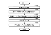
- FIG. 7 is a flowchart showing a method of manufacturing the treatment tool.
- FIG. 8 is a diagram illustrating a method for manufacturing a treatment tool.
- FIG. 9 is a diagram showing a seat heater according to the second embodiment.
- FIG. 10 is a diagram showing a seat heater according to the third embodiment.
- FIG. 11 is a diagram showing a seat heater according to the third embodiment.
- FIG. 12 is a flowchart showing a method of manufacturing the treatment tool.
- FIG. 13 is a diagram illustrating a method for manufacturing a treatment tool.
- FIG. 14 is a diagram showing a modified
- FIG. 1 is a diagram showing a treatment system 1 according to the first embodiment.
- the treatment system 1 treats a target site in a living tissue by applying energy to a target site (hereinafter referred to as a target site).
- the treatment means, for example, coagulation and incision of a target site.
- the treatment system 1 includes a treatment tool 2 and a control device 3.
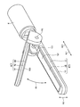
- the treatment tool 2 is, for example, a surgical treatment tool for treating a target site while passing through the abdominal wall.
- the treatment tool 2 includes a handle 5, a shaft 6, and a grip portion 7.
- the handle 5 is a part held by the operator.
- the handle 5 is provided with an operation knob 51 and a switch 52.
- the operation knob 51 accepts an opening / closing operation by the operator.
- the switch 52 receives an output start operation by the operator. Then, the switch 52 outputs an operation signal corresponding to the output start operation to the control device 3 via the electric cable C (FIG. 1).
- the shaft 6 has a substantially cylindrical shape.
- the central axis of the shaft 6 will be referred to as the central axis Ax (FIG. 1).
- one side along the central axis Ax will be referred to as the distal end side Ar1 (FIG. 1), and the other side will be referred to as the proximal end side Ar2 (FIG. 1).
- the end of the base end side Ar2 of the shaft 6 is connected to the handle 5.
- a grip portion 7 is attached to the end portion of the tip end side Ar1 of the shaft 6. Then, inside the shaft 6, an opening / closing mechanism for opening / closing the first and second gripping members 8 and 9 (FIG.
- FIG. 2 is a diagram showing a grip portion 7.
- the grip portion 7 is a portion that treats the target portion while gripping the target portion.
- the grip portion 7 includes first and second grip members 8 and 9.
- the first and second gripping members 8 and 9 are configured to be openable and closable in the direction of arrow R1 (FIG. 2) in response to an opening and closing operation of the operation knob 51 by the operator.
- FIGS. 3 and 4 are views showing the first gripping member 8.
- FIG. 3 is a cross-sectional view of the first gripping member 8 cut by a plane including the central axis Ax.
- FIG. 4 is a cross-sectional view of the first gripping member 8 cut along a plane orthogonal to the central axis Ax.
- the first gripping member 8 is arranged at a position facing the second gripping member 9.
- the first gripping member 8 includes a first jaw 10, a first support member 11, a blade 12, a seat heater 13 (FIGS. 3 and 4), and the like.
- a block 14 (FIGS. 3 and 4) is provided.
- the first jaw 10 is a portion in which a part of the shaft 6 extends to the tip end side Ar1, and is formed in a long shape extending along the central axis Ax.
- the first jaw 10 is made of a metal material such as a stainless alloy or a titanium alloy.
- the first support member 11 has an elongated shape extending along the central axis Ax, and is fixed to the upper surface in FIGS. 3 and 4 of the first jaw 10.
- a recess 111 extending from the base end of the first support member 11 toward the tip end side Ar1 is formed on the upper surface in FIGS. 3 and 4. .
- the first support member 11 supports the blade 12, the seat heater 13, and the block 14 in the recess 111.
- a resin material having electrical insulation such as PEEK (polyetheretherketone) and having a low thermal conductivity can be exemplified. That is, by disposing the first support member 11 having a low thermal conductivity between the blade 12 and the seat heater 13 and the first jaw 10, heat is transferred from the seat heater 13 to the first jaw 10. It is possible to efficiently transfer the heat from the seat heater 13 to the blade 12.
- PEEK polyetheretherketone
- the blade 12 has an elongated shape extending along the central axis Ax and is fixed in the recess 111.
- the blade 12 is made of a material having conductivity and excellent thermal conductivity, such as copper, aluminum, a copper alloy, and an aluminum alloy.
- the upper surface in FIGS. 3 and 4 comes into contact with the target portion while the target portion is gripped by the first and second gripping members 8 and 9. That is, the surface functions as a treatment surface 121 (FIGS. 2 to 4) for treating the target site.
- the treatment surface 121 has a direction A1 (in which the first and second gripping members 8 and 9 face each other in a state where the target portion is gripped by the first and second gripping members 8 and 9).
- the treatment surface 121 is formed of a flat surface, but the treatment surface 121 is not limited to this, and may be formed of other shapes such as a convex shape and a concave shape. The same applies to the gripping surface 931 described later in the second gripping member 9.
- a recess 123 (FIGS. 3 and 4) extending from the base end to the tip of the blade 12 is formed on the mounting surface 122 having a front-back relationship with the treatment surface 121. Then, the blade 12 supports the seat heater 13 and the block 14 by the bottom surface of the recess 123.
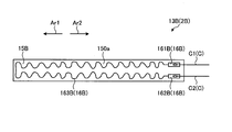
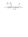
- FIG. 5 and 6 are views showing the seat heater 13. Specifically, FIG. 5 is a view of the state before the seat heater 13 is folded back as viewed from the first plate surface 150a side of the substrate 15.
- FIG. 6 is a cross-sectional view of the state after the seat heater 13 is folded back, cut by a plane orthogonal to the width direction (left-right direction in FIG. 4) of the seat heater 13. Note that, in FIG. 6, the block 14 is also shown for convenience of explanation. A part of the seat heater 13 generates heat when energized. As shown in FIG. 5 or 6, the sheet heater 13 includes a substrate 15 and a conductive portion 16.
- the substrate 15 is a sheet-shaped flexible substrate made of a resin material having electrical insulation such as polyimide.
- the substrate 15 is formed in a long shape, and has first and second wide portions 151 and 152 located at both ends in the longitudinal direction (left-right direction in FIG. 5), and the first and second wide portions. It is located between 151 and 152, and includes a narrow portion 153 that connects the first and second wide portions 151 and 152.
- the width dimension (length dimension in the vertical direction in FIG. 4) of the narrow portion 153 is set substantially uniformly along the longitudinal direction of the substrate 15. Further, the width dimension of the narrow portion 153 is set to be smaller than that of the first and second wide portions 151 and 152.
- the conductive portion 16 is vapor-deposited on the first plate surface 150a of the first plate surface 150a (FIGS. 5 and 6) and the second plate surface 150b (FIG. 6) having a front-back relationship with each other on the substrate 15. It is formed by patterning a metal thin film formed by or sputtering with photolithography. As shown in FIG. 5 or 6, the conductive portion 16 includes first and second connecting portions 161, 162, a heat generating portion 163, and an electric path portion 164.
- the first connecting portion 161 is located at the right end portion (corresponding to the first end according to the present invention) of the conductive portion 16 in FIG. 5, and is provided in the first wide portion 151. Has been done. Then, the first lead wire C1 (FIG. 6) constituting the electric cable C is electrically connected to the first connecting portion 161.
- the first lead wire C1 corresponds to the first wiring member according to the present invention.
- the second connecting portion 162 is located at the left end portion (corresponding to the second end according to the present invention) of the conductive portion 16 in FIG. 5, and is provided in the second wide portion 152. Has been done. Then, the second lead wire C2 (FIG. 6) constituting the electric cable C is electrically connected to the second connecting portion 162.
- the second lead wire C2 corresponds to the second wiring member according to the present invention.
- the heat generating portion 163 is connected to the first connecting portion 161 and the other end side extends toward the second connecting portion 162 side while meandering in a wavy shape, for example.
- the heat generating portion 163 is not limited to a shape that extends while meandering in a wavy shape, and may have a shape that extends linearly from the first connecting portion 161 toward the second connecting portion 162 side.
- the electric path portion 164 is a portion that serves as an energizing path between the second connecting portion 162 and the heat generating portion 163. That is, one end of the electric path portion 164 is connected to the other end of the heat generating portion 163.
- the end portion on the one end side will be referred to as the heat generation side end portion 164a (FIGS. 5 and 6).
- the electric path portion 164 extends linearly from the heat generating side end portion 164a toward the second connecting portion 162 side, and the other end is connected to the second connecting portion 162.
- the conductive portion 16 extends along the longitudinal direction of the substrate 15 on the first plate surface 150a. More specifically, the conductive portion 16 is connected in series in the order of the first connecting portion 161, the heat generating portion 163, the electric path portion 164, and the second connecting portion 162 along the longitudinal direction of the substrate 15. It is provided on the first plate surface 150a.
- the resistance value of the heat generating portion 163 is set to the first and second connecting portions 161, 162, the heating portion 163, and the electric path portion 164 to have a predetermined total length and cross-sectional area, respectively. It is set higher than the connection portions 161, 162 and the electric path portion 164 of the above. Specifically, the first and second connecting portions 161, 162 and the electric path portion 164 have a larger cross-sectional area than the heat generating portion 163. Therefore, when a voltage is applied to the first and second connection portions 161, 162 by passing through the first and second lead wires C1 and C2 under the control of the control device 3, heat is generated. Part 163 mainly generates heat.
- the sheet heater 13 described above is fixed to the bottom surface of the recess 123 by the adhesive sheet 17 (FIGS. 3 and 4) in a folded state.
- the adhesive sheet 17 is located between the bottom surface of the recess 123 and the sheet heater 13, and adheres the bottom surface and the sheet heater 13.
- the adhesive sheet 17 is formed by mixing a material having high thermal conductivity, high temperature resistance, and adhesiveness, for example, epoxy resin, with a ceramic having high thermal conductivity such as alumina and aluminum nitride. Has been done.
- the seat heater 13 is folded back so as to be orthogonal to the longitudinal direction of the substrate 15 and located substantially in the center of the longitudinal direction in a state where the first plate surface 150a constitutes the outer surface of the seat heater 13.
- the folding line Ln is not limited to a line Ln that is exactly orthogonal to the longitudinal direction of the substrate 15, but also includes a line that intersects the longitudinal direction within a predetermined angle range.
- the region on the first connecting portion 161 side with respect to the folding line Ln is referred to as the treatment side region Sp1
- the region on the second connecting portion 162 side with respect to the folding line Ln is referred to as the back side region Sp2.
- the electric path portion 164 is provided so as to straddle the turnaround line Ln. Therefore, the first connecting portion 161, the heat generating portion 163, and the heat generating side end portion 164a are located in the treatment side region Sp1. Further, in the back surface side region Sp2, the second connecting portion 162 and the region of the electric path portion 164 other than the heat generating side end portion 164a are located. Then, the sheet heater 13 is folded back along the folding line Ln as described above, and is fixed to the bottom surface by the adhesive sheet 17 in a state where the treatment side region Sp1 faces the bottom surface of the recess 123.
- the block 14 is a long flat plate extending along the central axis Ax, and is arranged inside the folded seat heater 13 as shown in FIG. Then, the block 14 prevents the conductive portion 16 from being disconnected at the folded portion of the seat heater 13.
- the end face of the distal end side Ar1 is formed by a curved surface 141 having a specific radius of curvature and whose center of curvature is parallel to the folding line Ln. Then, as shown in FIG. 6, the curved surface 141 abuts on the folded portion of the seat heater 13. By making the radius of curvature of the curved surface 141 as large as possible within the heater mounting region, disconnection can be prevented.
- the radius of curvature can be, for example, in the range of about 0.2 to 0.6 mm.
- the block 14 extends from the curved surface 141 toward the proximal end side Ar2 to a position facing the first connecting portion 161. Then, each part of the first and second connecting portions 161 and 162 (first and second wide portions 151 and 152) is in a state of projecting from the block 14 to the proximal end side Ar2, respectively.
- a material having electrical insulation and heat resistance is preferable, and a resin material such as PEEK, ceramic or the like can be exemplified.
- the upper surface of the block 14 in FIG. 6 is referred to as a pressing surface 142
- the lower surface of the block 14 in FIG. 6 is referred to as a back surface 143
- the base end side of the block 14 is described.
- the surface of Ar2 is referred to as a base end surface 144.
- the second gripping member 9 includes a second jaw 91, a second support member 92, and a facing plate 93.
- the second jaw 91 has an elongated shape extending along the central axis Ax. Then, in the second jaw 91, the end portion of the base end side Ar2 is rotatably supported with respect to the shaft 6 about the fulcrum P0 (FIG. 2), and by rotating, the first gripping member 8 Opens and closes against.
- the first gripping member 8 is fixed to the shaft 6, and the second gripping member 9 is pivotally supported by the shaft 6, but the present invention is not limited to this.
- a configuration may be adopted in which both the first and second gripping members 8 and 9 are pivotally supported by the shaft 6 and the first and second gripping members 8 and 9 are opened and closed by rotating each of them. Absent. Further, for example, the first gripping member 8 is pivotally supported by the shaft 6, the second gripping member 9 is fixed to the shaft 6, and the first gripping member 8 rotates to the second gripping member 9. On the other hand, a configuration that opens and closes may be adopted.
- the second support member 92 is made of a resin material having electrical insulation such as PEEK and having a low thermal conductivity, and is arranged between the second jaw 91 and the facing plate 93. ing.
- the facing plate 93 is made of a conductive material such as copper, and is fixed on a surface of the second supporting member 92 facing the first gripping member 8. In the facing plate 93, the surface on the side of the first gripping member 8 functions as a gripping surface 931 (FIG. 2) for gripping the target portion with the treatment surface 121.
- Control device configuration The treatment tool 2 is detachably connected to the control device 3 by the electric cable C. Then, the control device 3 is electrically connected to the switch 52 via the electric cable C. Further, the control device 3 is electrically connected to the conductive portion 16 via the electric cables C (first and second lead wires C1 and C2). Further, the control device 3 is electrically connected to the blade 12 and the facing plate 93, respectively, via the electric cable C. Then, the control device 3 executes the following treatment control in response to the operation signal from the switch 52.
- the control device 3 applies a voltage to the first and second connection portions 161, 162 by passing through the first and second lead wires C1 and C2.
- the control device 3 measures the resistance value of the conductive portion 16 (hereinafter referred to as heater resistance) from the voltage value and the current value supplied to the conductive portion 16 by using, for example, a voltage drop method.
- the control device 3 refers to the resistance temperature characteristics measured in advance.
- the resistance temperature characteristic is a characteristic showing the relationship between the heater resistance and the temperature of the heat generating portion 163 (hereinafter, referred to as the heater temperature). Then, the control device 3 controls the heater resistance to a target resistance value corresponding to the target temperature in the resistance temperature characteristic while changing the electric power supplied to the conductive unit 16.
- the heater temperature is controlled to the target temperature.
- the heat from the heat generating portion 163 controlled to the target temperature is transferred to the target portion gripped between the first and second gripping members 8 and 9 via the blade 12. In other words, thermal energy is applied to the target portion.
- control device 3 supplies high-frequency power to the blade 12 and the facing plate 93 by passing through the electric cable C substantially at the same time as applying the thermal energy to the target portion described above.
- a high-frequency current flows through the target portion gripped between the blade 12 and the facing plate 93.
- high frequency energy is applied to the target portion.
- the blade 12 and the counter plate 93 also have a function as an electrode to which high frequency power is supplied and a high frequency current is passed to the target portion.
- the target portion is heated by the above-mentioned application of thermal energy.
- Joule heat is generated by the high frequency current flowing through the target portion.
- the target site is treated.
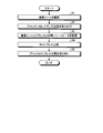
- FIG. 7 is a flowchart showing a method of manufacturing the treatment tool 2.
- FIG. 8 is a diagram illustrating a method of manufacturing the treatment tool 2. In the following, for convenience of explanation, only a method of attaching the seat heater 13 and the block 14 to the blade 12 will be described as a method of manufacturing the treatment tool 2.
- step S1 adhesive sheet arrangement step
- step S2 the operator attaches the press jig 200 to the block 14 as shown in FIGS. 8 (b) and 8 (c) (step S2: jig attaching step).
- the press jig 200 includes a jig main body 210, a first fixing portion 220, and a second fixing portion 230.
- the jig body 210 is detachably connected to the block 14. More specifically, as shown in FIG. 8 (b) or FIG. 8 (c), the back surface 143 and the base end surface 144 of the block 14 are provided with a plurality of recesses 145 (three in the first embodiment). ing.
- a plurality of locking projections 211 that are locked to the plurality of recesses 145 are provided on the outer surface of the jig main body 210. Then, the jig main body 210 is attached to the block 14 as shown below.
- the operator inserts the plurality of locking projections 211 of the jig main body 210 into the plurality of recesses 145 from the upper side in FIG. 8B with respect to the block 14, and the jig is inserted into the block 14 from the upper side.
- the main body 210 is slid to the left in FIG. 8 (b).
- the plurality of locking projections 211 are respectively locked in the plurality of recesses 145, and the jig body 210 is attached to the block 14.
- the plurality of recesses 145 are not limited to the shape shown in FIG. 8, and for example, the block 14 may have a shape that penetrates in a direction orthogonal to the paper surface of FIG.
- the operator attaches a plurality of locking projections 211 of the jig main body 210 to the plurality of recesses 145 from the side orthogonal to the paper surface of FIG. 8B (the side surface side of the block 14) with respect to the block 14. insert.
- the plurality of locking projections 211 are respectively locked in the plurality of recesses 145, and the jig body 210 is attached to the block 14.
- the first and second fixing portions 220 and 230 are detachably connected to the jig main body 210. Then, the first and second fixing portions 220 and 230 can sandwich the seat heater 13 with the jig main body 210, respectively.
- step S2 the worker performs step S2 as shown below.
- the operator attaches the jig body 210 to the block 14.
- the operator blocks the second plate surface 150b of the seat heater 13 in a state where the folding line Ln of the seat heater 13 is located on the curved surface 141 of the block 14. It comes into contact with the pressing surface 142 and the curved surface 141.
- the operator attaches the first fixing portion 220 to the jig main body 210 so that the portion of the seat heater 13 on the first wide portion 151 side is between the jig main body 210 and the first fixing portion 220. Hold it with.
- the operator attaches the second fixing portion 230 to the jig main body 210 so that the portion of the seat heater 13 on the second wide portion 152 side is between the jig main body 210 and the second fixing portion 230. Hold it with.
- the seat heater 13 is positioned with respect to the block 14 and the press jig 200 in a state of being folded back along the curved surface 141 (a state of being folded back along the folding line Ln).
- step S2 the operator moves the press jig 200 to a position where the pressing surface 142 faces the uncured adhesive sheet 17 (step S3: sheet heater arranging step). .. As a result, the sheet heater 13 is arranged between the uncured adhesive sheet 17 and the block 14.
- step S3 the operator presses (presses) the block 14 toward the bottom surface of the recess 123 with the press jig 200 to bring the uncured adhesive sheet 17 into a compressed state. Further, the operator heats the compressed unit (blade 12, sheet heater 13, block 14, and press jig 200) by putting it in a curing furnace (step S4: hot press step). As a result, the uncured adhesive sheet 17 is cured, and the adhesive sheet 17 adheres and fixes the sheet heater 13 and the pressing surface 142 of the block 14 to the bottom surface of the recess 123.
- the press device itself may be provided with a heating mechanism so that it can be heated at the same time as the press.
- step S4 the operator removes the press jig 200 from the block 14 as shown in FIG. 8 (e) (step S5: jig removal step).
- the conductive portion 16 extends along the longitudinal direction of the substrate 15 on the first plate surface 150a. Then, the seat heater 13 is folded back along the folding line Ln in a state where the first plate surface 150a constitutes the outer surface. That is, it is not necessary to parallel the two electric paths in the width direction of the substrate 15, and the width dimension of the substrate 15 can be reduced. Further, the block 14 is arranged inside the seat heater 13 folded along the folding line Ln. Therefore, the block 14 can limit the curvature of the folded portion of the seat heater 13 from becoming too small, and can prevent the conductive portion 16 from being disconnected.
- the seat heater 13 is folded back along the curved surface 141 of the block 14. Therefore, the curvature of the folded portion of the seat heater 13 can be set to be the same as the curvature of the curved surface 141. That is, the curvature of the folded portion can be set to a desired curvature, and the disconnection of the conductive portion 16 can be prevented more reliably.
- the block 14 is made of a material such as a resin having electrical insulation and heat insulation (or lower thermal conductivity than the blade 12). Further, the block 14 extends from the curved surface 141 toward the proximal end side Ar2 to a position facing the first connecting portion 161. That is, between the treatment side region Sp1 in the conductive portion 16 and the back surface side region Sp2 in the conductive portion 16, there are a substrate 15 and a block 14 having electrical insulation properties, respectively. Therefore, a sufficient creepage distance between the treatment side region Sp1 in the conductive portion 16 and the back surface region Sp2 in the conductive portion 16 can be sufficiently secured, and a short circuit occurs between the treatment side region Sp1 and the back surface region Sp2. It can be prevented from occurring.
- the block 14 is provided with a recess 145. Therefore, by making the air layer in the recess 145 function as a heat insulating layer, the heat insulating property of the block 14 can be further improved by both the heat insulating property of the material (resin or the like) of the block 14 itself and the heat insulating layer. It is possible to efficiently transfer the heat from the heat generating portion 163 to the blade 12.
- the conductive portion 16 has a first connecting portion 161, a heat generating portion 163, an electric path portion 164, and a second connecting portion along the longitudinal direction of the substrate 15. It is provided on the first plate surface 150a in a state of being connected in series in the order of 162.
- the electric path portion 164 is provided so as to straddle the turnaround line Ln. That is, in the state where the seat heater 13 is folded back along the folding line Ln, the electric path portion 164 is folded back.
- the electric path portion 164 has a larger cross-sectional area than the heat generating portion 163. Therefore, the disconnection of the conductive portion 16 can be further prevented as compared with the case where the heat generating portion 163 is folded back.
- the seat heater 13 is attached to the blade 12 as shown below. That is, after the step S1, the operator arranges the sheet heater 13 (treatment side region Sp1) on the uncured adhesive sheet 17. After that, the operator compresses the uncured adhesive sheet 17 by directly pressing the sheet heater 13 (treatment side region Sp1) toward the bottom surface of the recess 123 with a press jig, and does not apply heat. The cured adhesive sheet 17 is cured. Then, when the sheet heater 13 is attached to the blade 12 as described above, the adhesive sheet 17 may stick to the press jig. In this case, there is a problem that the seat heater 13 itself may be destroyed or damaged when the press jig is peeled off. According to the method for manufacturing the treatment tool 2 according to the first embodiment (steps S1 to S5), since the block 14 is provided, the adhesive sheet 17 does not stick to the press jig 200. That is, the above-mentioned problem does not occur.
- the seat heater 13 is positioned with respect to the block 14 and the press jig 200. Therefore, the bonding position of the seat heater 13 with respect to the blade 12 can be made constant, and the performance does not vary.
- FIG. 9 is a diagram showing the seat heater 13A according to the second embodiment. Specifically, FIG. 9 is a cross-sectional view corresponding to FIG. As shown in FIG. 9, the treatment tool 2A according to the second embodiment employs the seat heater 13A in which the cover member 18 is added to the seat heater 13 described in the first embodiment described above.
- the cover member 18 is provided on the first plate surface 150a of the substrate 15 so as to straddle the folding line Ln. Specifically, the cover member 18 extends from a position with a predetermined gap from the heat generating side end portion 164a toward the second connecting portion 162 side to the second connecting portion 162 side, and extends from the electric path portion 164. Cover the surface. That is, the cover member 18 covers a region of the electric path portion 164 other than the heat generating side end portion 164a.
- the cover member 18 described above is made of a material having electrical insulation such as a coverlay, a sealing material, or a melt layer of polyimide.
- the seat heater 13A according to the second embodiment is provided with a cover member 18. Therefore, the cover member 18 can improve the watertightness of the back surface region Sp2 in the conductive portion 16. Further, since the cover member 18 has electrical insulation, even when a liquid enters the recess 111, a short circuit occurs between the treatment side region Sp1 in the conductive portion 16 and the back surface side region Sp2 in the conductive portion 16. It can be prevented from occurring. Further, the cover member 18 covers a region of the electric path portion 164 other than the heat generating side end portion 164a.
- the cover member 18 since the cover member 18 is provided at a position avoiding the heat generating side end portion 164a, which tends to become hot, the cover member 18 does not become hot, and the cover member 18 can be moved from the first plate surface 150a. It is possible to prevent it from peeling off.
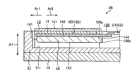
- FIG. 10 and 11 are views showing the seat heater 13B according to the third embodiment.
- FIG. 10 is a view of the seat heater 13B viewed from the first plate surface 150a side.
- FIG. 11 is a cross-sectional view corresponding to FIG.
- the treatment tool 2B according to the third embodiment employs a seat heater 13B different from the seat heater 13 described in the first embodiment described above.
- the seat heater 13B is not folded back unlike the seat heater 13 described in the first embodiment described above.
- the sheet heater 13B includes a substrate 15B and a conductive portion 16B (FIG. 10).
- the substrate 15B is a sheet-like substrate made of a resin material having electrical insulation such as polyimide, and its width dimension (length dimension in the vertical direction in FIG. 10) is its longitudinal direction (left and right in FIG. 10). It is set almost uniformly along the direction).
- the conductive portion 16B is vapor-deposited on the first plate surface 150a of the first plate surface 150a (FIGS. 10 and 11) and the second plate surface 150b (FIG. 11) having a front-back relationship with each other in the substrate 15B. It is formed by patterning a metal thin film formed by or sputtering with photolithography. As shown in FIG. 10, the conductive portion 16B includes first and second connecting portions 161B and 162B, and a heat generating portion 163B.
- the first and second connecting portions 161B and 162B extend along the longitudinal direction of the substrate 15B, and at the proximal end side Ar2 of the first plate surface 150a, the substrate 15B They are arranged side by side in the width direction. Then, the first lead wire C1 (FIGS. 10 and 11) constituting the electric cable C is electrically connected to the first connection portion 161B. Further, a second lead wire C2 (FIGS. 10 and 11) constituting the electric cable C is electrically connected to the second connection portion 162B.
- the heat generating portion 163B extends on the first plate surface 150a while meandering from the proximal end side Ar2 toward the distal end side Ar1, and is folded back at the distal end side Ar1 to form a wavy shape toward the proximal end side Ar2. It has a substantially U-shape that extends while meandering. Then, both ends of the heat generating portion 163B are connected to the first and second connecting portions 161B and 162B, respectively.
- the resistance value of the heat generating portion 163B is determined by setting the first and second connecting portions 161B and 162B and the heat generating portion 163B to a predetermined total length and cross-sectional area, respectively, so that the first and second connecting portions 161B, It is set higher than 162B. Therefore, when a voltage is applied to the first and second connection portions 161B and 162B by passing through the first and second lead wires C1 and C2 under the control of the control device 3, heat is generated. Part 163B mainly generates heat.
- FIG. 12 is a flowchart showing a method of manufacturing the treatment tool 2B.
- FIG. 13 is a diagram illustrating a method of manufacturing the treatment tool 2B. In the following, for convenience of explanation, only a method of attaching the seat heater 13B and the block 14 to the blade 12 will be described as a method of manufacturing the treatment tool 2B.
- step S1B adhesive sheet arrangement step
- step S2B jig attaching step.
- the press jig 200B has substantially the same configuration as the jig main body 210 in the press jig 200 described in the first embodiment described above. That is, in step S2B, the operator attaches the press jig 200B to the block 14 by locking the plurality of locking projections 211 of the press jig 200B into the plurality of recesses 145, respectively.
- step S2B the operator arranges the sheet heater 13B on the uncured adhesive sheet 17 in a posture in which the first plate surface 150a faces the adhesive sheet 17.
- step S3B seat heater arranging step.
- the sheet heater 13B is arranged between the uncured adhesive sheet 17 and the block 14.
- step S3B the operator presses (presses) the block 14 toward the bottom surface of the recess 123 with the press jig 200B to bring the uncured adhesive sheet 17 into a compressed state. Further, the operator heats the compressed unit (blade 12, sheet heater 13B, block 14, and press jig 200B) by putting it in a curing furnace (step S4B: hot press step). As a result, the uncured adhesive sheet 17 is cured, and the sheet heater 13B and the block 14 are adhesively fixed to the bottom surface of the recess 123 by the adhesive sheet 17.
- the press device itself may be provided with a heating mechanism so that it can be heated at the same time as the press.
- step S4B the operator removes the press jig 200B from the block 14 as shown in FIG. 13 (d) (step S5B: jig removal step).
- the block 14 is provided with a recess 145. Therefore, by making the air layer in the recess 145 function as a heat insulating layer, the heat transfer from the heat generating portion 163 to the back surface side region Sp2 is restricted, and the heat from the heat generating portion 163 is efficiently transferred to the blade 12. It becomes possible.
- the seat heater 13B is attached to the blade 12 as shown below. That is, after the step S1B, the operator arranges the sheet heater 13B on the uncured adhesive sheet 17. After that, the operator compresses the uncured adhesive sheet 17 by pressing the sheet heater 13B directly toward the bottom surface of the recess 123 with a press jig, and applies heat to the uncured adhesive sheet 17. To cure. Then, when the sheet heater 13B is attached to the blade 12 as described above, the adhesive sheet 17 may stick to the press jig. In this case, there is a problem that the seat heater 13B itself may be destroyed or damaged when the press jig is peeled off.
- step S1B to S5B since the block 14 is provided, the adhesive sheet 17 does not stick to the press jig 200B. That is, the above-mentioned problem does not occur.
- the present invention should not be limited only to the above-described first to third embodiments.
- the block 14 is in contact with the folded portion of the seat heaters 13 and 13A, but the present invention is not limited to this, and a configuration in which the block 14 is not in contact with the folded portion may be adopted. I do not care.
- both thermal energy and high frequency energy are applied to the target portion, but the present invention is not limited to this, and only thermal energy is applied. (A configuration in which the target portion is treated only by the heat from the seat heaters 13 and 13B) may be adopted.
- FIG. 14 is a diagram showing a modified example of the first to third embodiments.
- the recess 145 is used as the heat insulating layer provided on the block 14, but the present invention is not limited to this.
- a through hole 146 penetrating the block 14C may be formed, and the air layer in the through hole 146 may function as a heat insulating layer. That is, the block 14C is composed of a hollow member.
Abstract
This treatment instrument comprises: a blade 12 having a treatment surface 121 that treats biological tissue, and a mounting surface 122 that has a front/back relationship with the treatment surface 121; a sheet heater 13 having a substrate that is formed from a material having electrical insulation properties, a conduction part that has a heat generating part that generates heat by conduction, the substrate having a first sheet surface 150a and a second sheet surface 150b that have a front/back relationship with each other, and the conduction part extending along the longitudinal direction of the substrate on the first sheet surface 150a; and a block 14. The first sheet surface 150a forms the outer surface of the sheet heater 13, the sheet heater 13 is folded along a fold line orthogonal to the longitudinal direction of the substrate, and the heat generating part is positioned opposite the mounting surface 122. The block 14 is positioned to the inside of the sheet heater 13 that has been folded along the fold line.
Description
本発明は、処置具、及び処置具の製造方法に関する。
The present invention relates to a treatment tool and a method for manufacturing the treatment tool.
従来、生体組織における処置の対象となる部位(以下、対象部位と記載)に対してエネルギを付与することによって当該対象部位を処置する処置具が知られている(例えば、特許文献1参照)。
特許文献1に記載の処置具は、対象部位を把持する一対の把持部材を備える。当該把持部材には、通電によって発熱するシートヒータと、一対の把持部材によって対象部位を把持した際に当該対象部位に対して接触するブレードとが設けられている。そして、当該処置具では、ブレードを経由することによって、一対の把持部材によって把持された対象部位に対してシートヒータの熱を伝達させる。これによって、対象部位は、処置される。 Conventionally, a treatment tool for treating a target site in a living tissue by applying energy to a target site (hereinafter referred to as a target site) has been known (see, for example, Patent Document 1).
The treatment tool described inPatent Document 1 includes a pair of gripping members that grip the target portion. The gripping member is provided with a seat heater that generates heat when energized, and a blade that comes into contact with the target portion when the target portion is gripped by a pair of gripping members. Then, in the treatment tool, the heat of the seat heater is transferred to the target portion gripped by the pair of gripping members via the blade. As a result, the target site is treated.
特許文献1に記載の処置具は、対象部位を把持する一対の把持部材を備える。当該把持部材には、通電によって発熱するシートヒータと、一対の把持部材によって対象部位を把持した際に当該対象部位に対して接触するブレードとが設けられている。そして、当該処置具では、ブレードを経由することによって、一対の把持部材によって把持された対象部位に対してシートヒータの熱を伝達させる。これによって、対象部位は、処置される。 Conventionally, a treatment tool for treating a target site in a living tissue by applying energy to a target site (hereinafter referred to as a target site) has been known (see, for example, Patent Document 1).
The treatment tool described in
また、特許文献1に記載のシートヒータは、基板と、当該基板上に設けられた導電部とを備える。当該導電部は、配線部材がそれぞれ電気的に接続される第1,第2の接続部と、通電によって発熱する発熱部とを備える。当該第1,第2の接続部は、基板の基端側において、当該基板の幅方向に並設されている。また、当該発熱部は、基板上において、基端側から先端側に向けて延在するとともに、先端側において折り返し、基端側に向けて延在する略U字形状を有する。そして、当該発熱部の両端は、第1,第2の接続部に対してそれぞれ接続する。すなわち、導電部は、基板の幅方向に並列した2本の電気経路を有する。
Further, the sheet heater described in Patent Document 1 includes a substrate and a conductive portion provided on the substrate. The conductive portion includes first and second connecting portions to which the wiring members are electrically connected, and a heat generating portion that generates heat when energized. The first and second connecting portions are arranged side by side in the width direction of the substrate on the base end side of the substrate. Further, the heat generating portion has a substantially U-shape extending from the proximal end side toward the distal end side, folded back on the distal end side, and extending toward the proximal end side on the substrate. Then, both ends of the heat generating portion are connected to the first and second connecting portions, respectively. That is, the conductive portion has two electric paths parallel to each other in the width direction of the substrate.
ところで、特許文献1に記載のシートヒータでは、基板の幅方向に並列した2本の電気経路を有する。そして、当該2本の電気経路の短絡を防止するためには、当該2本の電気経路を十分に離間する必要がある。すなわち、基板の幅寸法が大きくなってしまう、という問題がある。
By the way, the sheet heater described in Patent Document 1 has two electric paths arranged in parallel in the width direction of the substrate. Then, in order to prevent the two electric paths from being short-circuited, it is necessary to sufficiently separate the two electric paths. That is, there is a problem that the width dimension of the substrate becomes large.
そこで、上述した問題を解消するために、以下の構成を有するシートヒータ(以下、折り返し型シートヒータと記載)を採用することが考えられる。
折り返し型シートヒータでは、導電部は、基板の長手方向に沿って延在する。そして、折り返し型シートヒータは、第1の板面が当該折り返し型シートヒータの外表面を構成する状態で、基板の長手方向に交差する折り返し線に沿って折り返される。
以上の構成を採用することによって、基板の幅方向に2本の電気経路を並列する必要がなく、当該基板の幅寸法を小さくすることができる。
しかしながら、折り返し型シートヒータでは、折り返し部分の曲率が小さくなり過ぎると、導電部に断線が生じてしまう虞がある、という問題がある。 Therefore, in order to solve the above-mentioned problem, it is conceivable to adopt a seat heater having the following configuration (hereinafter, referred to as a folded seat heater).
In the folded sheet heater, the conductive portion extends along the longitudinal direction of the substrate. Then, the folded-back type sheet heater is folded back along the folded-back line intersecting in the longitudinal direction of the substrate with the first plate surface forming the outer surface of the folded-back type sheet heater.
By adopting the above configuration, it is not necessary to parallel the two electric paths in the width direction of the substrate, and the width dimension of the substrate can be reduced.
However, the folded-back type sheet heater has a problem that if the curvature of the folded-back portion becomes too small, the conductive portion may be broken.
本発明は、上記に鑑みてなされたものであって、基板の幅寸法を小さくすることができ、かつ、導電部の断線を防止することができる処置具、及び処置具の製造方法を提供することを目的とする。
The present invention has been made in view of the above, and provides a treatment tool capable of reducing the width dimension of the substrate and preventing disconnection of the conductive portion, and a method for manufacturing the treatment tool. The purpose is.
上述した課題を解決し、目的を達成するために、本発明に係る処置具は、生体組織を処置する処置面と、前記処置面と表裏の関係を持つ実装面とを有するブレードと、電気絶縁性を有する材料によって構成された基板と、通電によって発熱する発熱部を有する導電部とを有するシートヒータであって、前記基板が互いに表裏の関係を持つ第1の板面及び第2の板面を有し、前記導電部が前記第1の板面上において前記基板の長手方向に沿って延在するシートヒータと、ブロックと、を備え、前記シートヒータは、前記第1の板面が前記シートヒータの外表面を構成する状態で、前記長手方向に交差する折り返し線に沿って折り返され、前記発熱部が前記実装面に対向する状態で設置され、前記ブロックは、前記折り返し線に沿って折り返された前記シートヒータの内側に配置されている。
In order to solve the above-mentioned problems and achieve the object, the treatment tool according to the present invention comprises a blade having a treatment surface for treating a living tissue, a mounting surface having a front-back relationship with the treatment surface, and electrical insulation. A sheet heater having a substrate made of a material having properties and a conductive portion having a heat generating portion that generates heat when energized, and the first plate surface and the second plate surface in which the substrates have a front and back relationship with each other. The sheet heater includes a sheet heater and a block in which the conductive portion extends along the longitudinal direction of the substrate on the first plate surface, and the sheet heater has the first plate surface. The outer surface of the seat heater is folded back along the folding line intersecting in the longitudinal direction, and the heat generating portion is installed so as to face the mounting surface, and the block is installed along the folding line. It is arranged inside the folded seat heater.
また、本発明に係る処置具の製造方法は、生体組織を処置するブレードの実装面上に、未硬化状態の接着シートを配置する接着シート配置工程と、ブロックに対してプレス冶具を取り付ける冶具取付工程と、前記未硬化状態の接着シートと前記ブロックとの間にシートヒータを配置するシートヒータ配置工程と、前記プレス冶具によって前記ブロックを前記実装面に向けて押圧することによって前記未硬化状態の接着シートを圧縮するとともに熱を加えることによって前記未硬化状態の接着シートを硬化させるホットプレス工程と、前記ブロックから前記プレス冶具を取り外す冶具取り外し工程と、を備える。
Further, the method for manufacturing the treatment tool according to the present invention includes a bonding sheet arranging step of arranging an uncured adhesive sheet on a mounting surface of a blade for treating a living tissue, and a jig mounting for attaching a press jig to a block. The uncured state is formed by the step, the sheet heater arranging step of arranging the sheet heater between the uncured adhesive sheet and the block, and pressing the block toward the mounting surface by the press jig. The present invention includes a hot pressing step of curing the uncured adhesive sheet by compressing the adhesive sheet and applying heat, and a jig removing step of removing the press jig from the block.
本発明に係る処置具、及び処置具の製造方法によれば、基板の幅寸法を小さくすることができ、かつ、導電部の断線を防止することができる。
According to the treatment tool according to the present invention and the method for manufacturing the treatment tool, the width dimension of the substrate can be reduced and the disconnection of the conductive portion can be prevented.
以下に、図面を参照して、本発明を実施するための形態(以下、実施の形態)について説明する。なお、以下に説明する実施の形態によって本発明が限定されるものではない。さらに、図面の記載において、同一の部分には同一の符号を付している。
Hereinafter, embodiments for carrying out the present invention (hereinafter referred to as embodiments) will be described with reference to the drawings. The present invention is not limited to the embodiments described below. Further, in the description of the drawings, the same parts are designated by the same reference numerals.
(実施の形態1)
〔処置システムの概略構成〕
図1は、本実施の形態1に係る処置システム1を示す図である。
処置システム1は、生体組織における処置の対象となる部位(以下、対象部位と記載)に対してエネルギを付与することによって、当該対象部位を処置する。ここで、当該処置とは、例えば、対象部位の凝固及び切開を意味する。この処置システム1は、図1に示すように、処置具2と、制御装置3とを備える。 (Embodiment 1)
[Outline configuration of treatment system]
FIG. 1 is a diagram showing atreatment system 1 according to the first embodiment.
Thetreatment system 1 treats a target site in a living tissue by applying energy to a target site (hereinafter referred to as a target site). Here, the treatment means, for example, coagulation and incision of a target site. As shown in FIG. 1, the treatment system 1 includes a treatment tool 2 and a control device 3.
〔処置システムの概略構成〕
図1は、本実施の形態1に係る処置システム1を示す図である。
処置システム1は、生体組織における処置の対象となる部位(以下、対象部位と記載)に対してエネルギを付与することによって、当該対象部位を処置する。ここで、当該処置とは、例えば、対象部位の凝固及び切開を意味する。この処置システム1は、図1に示すように、処置具2と、制御装置3とを備える。 (Embodiment 1)
[Outline configuration of treatment system]
FIG. 1 is a diagram showing a
The
〔処置具の構成〕
処置具2は、例えば、腹壁を通した状態で対象部位を処置するための外科医療用処置具である。この処置具2は、図1に示すように、ハンドル5と、シャフト6と、把持部7とを備える。
ハンドル5は、術者が手で持つ部分である。そして、このハンドル5には、図1に示すように、操作ノブ51と、スイッチ52とが設けられている。
操作ノブ51は、術者による開閉操作を受け付ける。
スイッチ52は、術者による出力開始操作を受け付ける。そして、スイッチ52は、電気ケーブルC(図1)を経由することによって、制御装置3に対して当該出力開始操作に応じた操作信号を出力する。 [Structure of treatment tool]
Thetreatment tool 2 is, for example, a surgical treatment tool for treating a target site while passing through the abdominal wall. As shown in FIG. 1, the treatment tool 2 includes a handle 5, a shaft 6, and a grip portion 7.
Thehandle 5 is a part held by the operator. Then, as shown in FIG. 1, the handle 5 is provided with an operation knob 51 and a switch 52.
Theoperation knob 51 accepts an opening / closing operation by the operator.
Theswitch 52 receives an output start operation by the operator. Then, the switch 52 outputs an operation signal corresponding to the output start operation to the control device 3 via the electric cable C (FIG. 1).
処置具2は、例えば、腹壁を通した状態で対象部位を処置するための外科医療用処置具である。この処置具2は、図1に示すように、ハンドル5と、シャフト6と、把持部7とを備える。
ハンドル5は、術者が手で持つ部分である。そして、このハンドル5には、図1に示すように、操作ノブ51と、スイッチ52とが設けられている。
操作ノブ51は、術者による開閉操作を受け付ける。
スイッチ52は、術者による出力開始操作を受け付ける。そして、スイッチ52は、電気ケーブルC(図1)を経由することによって、制御装置3に対して当該出力開始操作に応じた操作信号を出力する。 [Structure of treatment tool]
The
The
The
The
シャフト6は、略円筒形状を有する。なお、以下では、シャフト6の中心軸を中心軸Ax(図1)と記載する。また、以下では、中心軸Axに沿う一方側を先端側Ar1(図1)と記載し、他方側を基端側Ar2(図1)と記載する。そして、シャフト6は、基端側Ar2の端部がハンドル5に対して接続されている。また、シャフト6における先端側Ar1の端部には、把持部7が取り付けられている。そして、このシャフト6の内部には、術者による操作ノブ51への開閉操作に応じて、把持部7を構成する第1,第2の把持部材8,9(図1)を開閉させる開閉機構(図示略)が設けられている。また、このシャフト6の内部には、電気ケーブルCがハンドル5を経由することによって基端側Ar2から先端側Ar1まで配設されている。
The shaft 6 has a substantially cylindrical shape. In the following, the central axis of the shaft 6 will be referred to as the central axis Ax (FIG. 1). Further, in the following, one side along the central axis Ax will be referred to as the distal end side Ar1 (FIG. 1), and the other side will be referred to as the proximal end side Ar2 (FIG. 1). The end of the base end side Ar2 of the shaft 6 is connected to the handle 5. Further, a grip portion 7 is attached to the end portion of the tip end side Ar1 of the shaft 6. Then, inside the shaft 6, an opening / closing mechanism for opening / closing the first and second gripping members 8 and 9 (FIG. 1) constituting the gripping portion 7 in response to an opening / closing operation of the operation knob 51 by the operator. (Not shown) is provided. Further, inside the shaft 6, an electric cable C is arranged from the proximal end side Ar2 to the distal end side Ar1 by passing through the handle 5.
〔把持部の構成〕
図2は、把持部7を示す図である。
把持部7は、対象部位を把持した状態で当該対象部位を処置する部分である。この把持部7は、図1または図2に示すように、第1,第2の把持部材8,9を備える。
第1,第2の把持部材8,9は、術者による操作ノブ51への開閉操作に応じて、矢印R1(図2)方向に開閉可能に構成されている。 [Structure of grip]
FIG. 2 is a diagram showing agrip portion 7.
Thegrip portion 7 is a portion that treats the target portion while gripping the target portion. As shown in FIG. 1 or 2, the grip portion 7 includes first and second grip members 8 and 9.
The first and second gripping members 8 and 9 are configured to be openable and closable in the direction of arrow R1 (FIG. 2) in response to an opening and closing operation of the operation knob 51 by the operator.
図2は、把持部7を示す図である。
把持部7は、対象部位を把持した状態で当該対象部位を処置する部分である。この把持部7は、図1または図2に示すように、第1,第2の把持部材8,9を備える。
第1,第2の把持部材8,9は、術者による操作ノブ51への開閉操作に応じて、矢印R1(図2)方向に開閉可能に構成されている。 [Structure of grip]
FIG. 2 is a diagram showing a
The
The first and second
〔第1の把持部材の構成〕
図3及び図4は、第1の把持部材8を示す図である。具体的に、図3は、中心軸Axを含む平面によって第1の把持部材8を切断した断面図である。図4は、中心軸Axに直交する平面によって第1の把持部材8を切断した断面図である。
第1の把持部材8は、第2の把持部材9に対向する位置に配設されている。この第1の把持部材8は、図2ないし図4に示すように、第1のジョー10と、第1の支持部材11と、ブレード12と、シートヒータ13(図3,図4)と、ブロック14(図3,図4)とを備える。 [Structure of the first gripping member]
3 and 4 are views showing the first grippingmember 8. Specifically, FIG. 3 is a cross-sectional view of the first gripping member 8 cut by a plane including the central axis Ax. FIG. 4 is a cross-sectional view of the first gripping member 8 cut along a plane orthogonal to the central axis Ax.
The firstgripping member 8 is arranged at a position facing the second gripping member 9. As shown in FIGS. 2 to 4, the first gripping member 8 includes a first jaw 10, a first support member 11, a blade 12, a seat heater 13 (FIGS. 3 and 4), and the like. A block 14 (FIGS. 3 and 4) is provided.
図3及び図4は、第1の把持部材8を示す図である。具体的に、図3は、中心軸Axを含む平面によって第1の把持部材8を切断した断面図である。図4は、中心軸Axに直交する平面によって第1の把持部材8を切断した断面図である。
第1の把持部材8は、第2の把持部材9に対向する位置に配設されている。この第1の把持部材8は、図2ないし図4に示すように、第1のジョー10と、第1の支持部材11と、ブレード12と、シートヒータ13(図3,図4)と、ブロック14(図3,図4)とを備える。 [Structure of the first gripping member]
3 and 4 are views showing the first gripping
The first
第1のジョー10は、シャフト6の一部を先端側Ar1に延在させた部分であり、中心軸Axに沿って延在する長尺状に形成されている。この第1のジョー10は、例えば、ステンレス合金やチタン合金等の金属材料によって構成されている。
第1の支持部材11は、中心軸Axに沿って延在する長尺形状を有し、第1のジョー10における図3及び図4中、上方側の面に固定される。
この第1の支持部材11において、図3及び図4中、上方側の面には、当該第1の支持部材11の基端から先端側Ar1に向けて延在した凹部111が形成されている。そして、第1の支持部材11は、凹部111内において、ブレード12、シートヒータ13、及びブロック14を支持する。 Thefirst jaw 10 is a portion in which a part of the shaft 6 extends to the tip end side Ar1, and is formed in a long shape extending along the central axis Ax. The first jaw 10 is made of a metal material such as a stainless alloy or a titanium alloy.
Thefirst support member 11 has an elongated shape extending along the central axis Ax, and is fixed to the upper surface in FIGS. 3 and 4 of the first jaw 10.
In thefirst support member 11, a recess 111 extending from the base end of the first support member 11 toward the tip end side Ar1 is formed on the upper surface in FIGS. 3 and 4. .. Then, the first support member 11 supports the blade 12, the seat heater 13, and the block 14 in the recess 111.
第1の支持部材11は、中心軸Axに沿って延在する長尺形状を有し、第1のジョー10における図3及び図4中、上方側の面に固定される。
この第1の支持部材11において、図3及び図4中、上方側の面には、当該第1の支持部材11の基端から先端側Ar1に向けて延在した凹部111が形成されている。そして、第1の支持部材11は、凹部111内において、ブレード12、シートヒータ13、及びブロック14を支持する。 The
The
In the
以上説明した第1の支持部材11を構成する材料としては、PEEK(ポリエーテルエーテルケトン)等の電気絶縁性を有し、かつ、低い熱伝導率を有する樹脂材料等を例示することができる。すなわち、ブレード12及びシートヒータ13と第1のジョー10との間に熱伝導率の低い第1の支持部材11を配設することによって、シートヒータ13から第1のジョー10に向かう熱の伝達を制限し、当該シートヒータ13からの熱を効率良くブレード12に伝達することが可能となる。
As the material constituting the first support member 11 described above, a resin material having electrical insulation such as PEEK (polyetheretherketone) and having a low thermal conductivity can be exemplified. That is, by disposing the first support member 11 having a low thermal conductivity between the blade 12 and the seat heater 13 and the first jaw 10, heat is transferred from the seat heater 13 to the first jaw 10. It is possible to efficiently transfer the heat from the seat heater 13 to the blade 12.
ブレード12は、中心軸Axに沿って延在する長尺形状を有し、凹部111内に固定されている。このブレード12は、例えば銅、アルミニウム、銅合金、アルミニウム合金等のように導電性を有し、熱伝導に優れた材料によって構成されている。
このブレード12において、図3及び図4中、上方側の面は、第1,第2の把持部材8,9によって対象部位を把持した状態で、当該対象部位に対して接触する。すなわち、当該面は、当該対象部位を処置する処置面121(図2~図4)として機能する。本実施の形態1では、処置面121は、第1,第2の把持部材8,9によって対象部位を把持した状態で当該第1,第2の把持部材8,9が互いに対向する方向A1(図2~図4)に対して直交する平坦面によって構成されている。
なお、処置面121は、平坦面によって構成されているが、これに限らず、凸形状や凹形状等のその他の形状によって構成しても構わない。第2の把持部材9における後述する把持面931も同様である。 Theblade 12 has an elongated shape extending along the central axis Ax and is fixed in the recess 111. The blade 12 is made of a material having conductivity and excellent thermal conductivity, such as copper, aluminum, a copper alloy, and an aluminum alloy.
In theblade 12, the upper surface in FIGS. 3 and 4 comes into contact with the target portion while the target portion is gripped by the first and second gripping members 8 and 9. That is, the surface functions as a treatment surface 121 (FIGS. 2 to 4) for treating the target site. In the first embodiment, the treatment surface 121 has a direction A1 (in which the first and second gripping members 8 and 9 face each other in a state where the target portion is gripped by the first and second gripping members 8 and 9). It is composed of flat surfaces orthogonal to FIGS. 2 to 4).
Thetreatment surface 121 is formed of a flat surface, but the treatment surface 121 is not limited to this, and may be formed of other shapes such as a convex shape and a concave shape. The same applies to the gripping surface 931 described later in the second gripping member 9.
このブレード12において、図3及び図4中、上方側の面は、第1,第2の把持部材8,9によって対象部位を把持した状態で、当該対象部位に対して接触する。すなわち、当該面は、当該対象部位を処置する処置面121(図2~図4)として機能する。本実施の形態1では、処置面121は、第1,第2の把持部材8,9によって対象部位を把持した状態で当該第1,第2の把持部材8,9が互いに対向する方向A1(図2~図4)に対して直交する平坦面によって構成されている。
なお、処置面121は、平坦面によって構成されているが、これに限らず、凸形状や凹形状等のその他の形状によって構成しても構わない。第2の把持部材9における後述する把持面931も同様である。 The
In the
The
また、ブレード12において、処置面121と表裏の関係を持つ実装面122には、当該ブレード12の基端から先端まで延在した凹部123(図3,図4)が形成されている。そして、ブレード12は、凹部123の底面によって、シートヒータ13及びブロック14を支持する。
Further, in the blade 12, a recess 123 (FIGS. 3 and 4) extending from the base end to the tip of the blade 12 is formed on the mounting surface 122 having a front-back relationship with the treatment surface 121. Then, the blade 12 supports the seat heater 13 and the block 14 by the bottom surface of the recess 123.
図5及び図6は、シートヒータ13を示す図である。具体的に、図5は、シートヒータ13を折り返す前の状態を基板15における第1の板面150a側から見た図である。図6は、シートヒータ13を折り返した後の状態を当該シートヒータ13の幅方向(図4中、左右方向)に直交する平面によって切断した断面図である。なお、図6では、説明の便宜上、ブロック14も図示している。
シートヒータ13は、通電によって一部が発熱する。このシートヒータ13は、図5または図6に示すように、基板15と、導電部16とを備える。 5 and 6 are views showing theseat heater 13. Specifically, FIG. 5 is a view of the state before the seat heater 13 is folded back as viewed from the first plate surface 150a side of the substrate 15. FIG. 6 is a cross-sectional view of the state after the seat heater 13 is folded back, cut by a plane orthogonal to the width direction (left-right direction in FIG. 4) of the seat heater 13. Note that, in FIG. 6, the block 14 is also shown for convenience of explanation.
A part of theseat heater 13 generates heat when energized. As shown in FIG. 5 or 6, the sheet heater 13 includes a substrate 15 and a conductive portion 16.
シートヒータ13は、通電によって一部が発熱する。このシートヒータ13は、図5または図6に示すように、基板15と、導電部16とを備える。 5 and 6 are views showing the
A part of the
基板15は、ポリイミド等の電気絶縁性を有する樹脂材料によって構成されたシート状のフレキシブル基板である。この基板15は、長尺状に形成され、長手方向(図5中、左右方向)の両端にそれぞれ位置する第1,第2の幅広部151,152と、当該第1,第2の幅広部151,152間に位置するとともに、当該第1,第2の幅広部151,152を接続する幅狭部153とを備える。
ここで、幅狭部153は、その幅寸法(図4中、上下方向の長さ寸法)が基板15の長手方向に沿って略均一に設定されている。また、幅狭部153における幅寸法は、第1,第2の幅広部151,152よりも小さく設定されている。 Thesubstrate 15 is a sheet-shaped flexible substrate made of a resin material having electrical insulation such as polyimide. The substrate 15 is formed in a long shape, and has first and second wide portions 151 and 152 located at both ends in the longitudinal direction (left-right direction in FIG. 5), and the first and second wide portions. It is located between 151 and 152, and includes a narrow portion 153 that connects the first and second wide portions 151 and 152.
Here, the width dimension (length dimension in the vertical direction in FIG. 4) of thenarrow portion 153 is set substantially uniformly along the longitudinal direction of the substrate 15. Further, the width dimension of the narrow portion 153 is set to be smaller than that of the first and second wide portions 151 and 152.
ここで、幅狭部153は、その幅寸法(図4中、上下方向の長さ寸法)が基板15の長手方向に沿って略均一に設定されている。また、幅狭部153における幅寸法は、第1,第2の幅広部151,152よりも小さく設定されている。 The
Here, the width dimension (length dimension in the vertical direction in FIG. 4) of the
導電部16は、基板15における互いに表裏の関係を持つ第1の板面150a(図5,図6)及び第2の板面150b(図6)のうち第1の板面150a上に、蒸着やスパッタ等で成膜した金属薄膜をフォトリソグラフィーによりパターンニングすることによって形成されている。この導電部16は、図5または図6に示すように、第1,第2の接続部161,162と、発熱部163と、電気経路部164とを備える。
The conductive portion 16 is vapor-deposited on the first plate surface 150a of the first plate surface 150a (FIGS. 5 and 6) and the second plate surface 150b (FIG. 6) having a front-back relationship with each other on the substrate 15. It is formed by patterning a metal thin film formed by or sputtering with photolithography. As shown in FIG. 5 or 6, the conductive portion 16 includes first and second connecting portions 161, 162, a heat generating portion 163, and an electric path portion 164.
第1の接続部161は、図5に示すように、導電部16における図5中、右側の端部(本発明に係る第1端に相当)に位置し、第1の幅広部151に設けられている。そして、第1の接続部161には、電気ケーブルCを構成する第1のリード線C1(図6)が電気的に接続される。当該第1のリード線C1は、本発明に係る第1の配線部材に相当する。
第2の接続部162は、図5に示すように、導電部16における図5中、左側の端部(本発明に係る第2端に相当)に位置し、第2の幅広部152に設けられている。そして、第2の接続部162には、電気ケーブルCを構成する第2のリード線C2(図6)が電気的に接続される。当該第2のリード線C2は、本発明に係る第2の配線部材に相当する。 As shown in FIG. 5, the first connectingportion 161 is located at the right end portion (corresponding to the first end according to the present invention) of the conductive portion 16 in FIG. 5, and is provided in the first wide portion 151. Has been done. Then, the first lead wire C1 (FIG. 6) constituting the electric cable C is electrically connected to the first connecting portion 161. The first lead wire C1 corresponds to the first wiring member according to the present invention.
As shown in FIG. 5, the second connectingportion 162 is located at the left end portion (corresponding to the second end according to the present invention) of the conductive portion 16 in FIG. 5, and is provided in the second wide portion 152. Has been done. Then, the second lead wire C2 (FIG. 6) constituting the electric cable C is electrically connected to the second connecting portion 162. The second lead wire C2 corresponds to the second wiring member according to the present invention.
第2の接続部162は、図5に示すように、導電部16における図5中、左側の端部(本発明に係る第2端に相当)に位置し、第2の幅広部152に設けられている。そして、第2の接続部162には、電気ケーブルCを構成する第2のリード線C2(図6)が電気的に接続される。当該第2のリード線C2は、本発明に係る第2の配線部材に相当する。 As shown in FIG. 5, the first connecting
As shown in FIG. 5, the second connecting
発熱部163は、一端が第1の接続部161に対して接続するとともに、他端側が第2の接続部162側に向けて、例えば、波状に蛇行しながら延在する。なお、発熱部163は、波状に蛇行しながら延在する形状に限らず、第1の接続部161から第2の接続部162側に向けて直線状に延在する形状としても構わない。
電気経路部164は、第2の接続部162と発熱部163との間の通電経路となる部分である。すなわち、電気経路部164の一端は、発熱部163の他端に対して接続する。以下、当該一端側の端部を発熱側端部164a(図5,図6)と記載する。また、電気経路部164は、発熱側端部164aから第2の接続部162側に向けて直線状に延在するとともに、他端が第2の接続部162に対して接続する。 One end of theheat generating portion 163 is connected to the first connecting portion 161 and the other end side extends toward the second connecting portion 162 side while meandering in a wavy shape, for example. The heat generating portion 163 is not limited to a shape that extends while meandering in a wavy shape, and may have a shape that extends linearly from the first connecting portion 161 toward the second connecting portion 162 side.
Theelectric path portion 164 is a portion that serves as an energizing path between the second connecting portion 162 and the heat generating portion 163. That is, one end of the electric path portion 164 is connected to the other end of the heat generating portion 163. Hereinafter, the end portion on the one end side will be referred to as the heat generation side end portion 164a (FIGS. 5 and 6). Further, the electric path portion 164 extends linearly from the heat generating side end portion 164a toward the second connecting portion 162 side, and the other end is connected to the second connecting portion 162.
電気経路部164は、第2の接続部162と発熱部163との間の通電経路となる部分である。すなわち、電気経路部164の一端は、発熱部163の他端に対して接続する。以下、当該一端側の端部を発熱側端部164a(図5,図6)と記載する。また、電気経路部164は、発熱側端部164aから第2の接続部162側に向けて直線状に延在するとともに、他端が第2の接続部162に対して接続する。 One end of the
The
以上のように、導電部16は、第1の板面150a上において、基板15の長手方向に沿って延在する。より具体的に、導電部16は、基板15の長手方向に沿って、第1の接続部161、発熱部163、電気経路部164、及び第2の接続部162の順に直列に接続する状態で第1の板面150a上に設けられている。
As described above, the conductive portion 16 extends along the longitudinal direction of the substrate 15 on the first plate surface 150a. More specifically, the conductive portion 16 is connected in series in the order of the first connecting portion 161, the heat generating portion 163, the electric path portion 164, and the second connecting portion 162 along the longitudinal direction of the substrate 15. It is provided on the first plate surface 150a.
そして、発熱部163の抵抗値は、第1,第2の接続部161,162、発熱部163、及び電気経路部164を所定の全長及び断面積にそれぞれ設定することによって、第1,第2の接続部161,162及び電気経路部164よりも高く設定されている。具体的に、第1,第2の接続部161,162及び電気経路部164は、発熱部163よりも断面積が大きい。このため、制御装置3による制御の下、第1,第2のリード線C1,C2を経由することによって、第1,第2の接続部161,162に対して電圧が印加されると、発熱部163が主に発熱する。
Then, the resistance value of the heat generating portion 163 is set to the first and second connecting portions 161, 162, the heating portion 163, and the electric path portion 164 to have a predetermined total length and cross-sectional area, respectively. It is set higher than the connection portions 161, 162 and the electric path portion 164 of the above. Specifically, the first and second connecting portions 161, 162 and the electric path portion 164 have a larger cross-sectional area than the heat generating portion 163. Therefore, when a voltage is applied to the first and second connection portions 161, 162 by passing through the first and second lead wires C1 and C2 under the control of the control device 3, heat is generated. Part 163 mainly generates heat.
以上説明したシートヒータ13は、折り返された状態で、接着シート17(図3,図4)によって凹部123の底面に対して固定される。
ここで、接着シート17は、凹部123の底面とシートヒータ13との間に位置し、当該底面とシートヒータ13とを接着する。この接着シート17としては、熱伝導率が高く、かつ、高温に耐え、接着性を有する材料、例えば、エポキシ樹脂に、アルミナや窒化アルミニウム等の熱伝導率の高いセラミックが混合されることによって形成されている。
シートヒータ13は、図6に示すように、第1の板面150aがシートヒータ13の外表面を構成する状態で、基板15の長手方向に直交するとともに当該長手方向の略中央に位置する折り返し線Ln(図5)に沿って折り返される。言い換えれば、シートヒータ13は、第2の板面150bが内側に位置する状態で、折り返し線Lnに沿って折り返される。この状態では、第1,第2の幅広部151,152同士が互いに対向する。
なお、折り返し線Lnとしては、基板15の長手方向に対して厳密に直交するもののみに限らず、所定の角度の範囲において、当該長手方向に対して交差するものも含むものである。 Thesheet heater 13 described above is fixed to the bottom surface of the recess 123 by the adhesive sheet 17 (FIGS. 3 and 4) in a folded state.
Here, theadhesive sheet 17 is located between the bottom surface of the recess 123 and the sheet heater 13, and adheres the bottom surface and the sheet heater 13. The adhesive sheet 17 is formed by mixing a material having high thermal conductivity, high temperature resistance, and adhesiveness, for example, epoxy resin, with a ceramic having high thermal conductivity such as alumina and aluminum nitride. Has been done.
As shown in FIG. 6, theseat heater 13 is folded back so as to be orthogonal to the longitudinal direction of the substrate 15 and located substantially in the center of the longitudinal direction in a state where the first plate surface 150a constitutes the outer surface of the seat heater 13. It wraps along the line Ln (FIG. 5). In other words, the seat heater 13 is folded back along the folding line Ln with the second plate surface 150b located inside. In this state, the first and second wide portions 151 and 152 face each other.
The folding line Ln is not limited to a line Ln that is exactly orthogonal to the longitudinal direction of thesubstrate 15, but also includes a line that intersects the longitudinal direction within a predetermined angle range.
ここで、接着シート17は、凹部123の底面とシートヒータ13との間に位置し、当該底面とシートヒータ13とを接着する。この接着シート17としては、熱伝導率が高く、かつ、高温に耐え、接着性を有する材料、例えば、エポキシ樹脂に、アルミナや窒化アルミニウム等の熱伝導率の高いセラミックが混合されることによって形成されている。
シートヒータ13は、図6に示すように、第1の板面150aがシートヒータ13の外表面を構成する状態で、基板15の長手方向に直交するとともに当該長手方向の略中央に位置する折り返し線Ln(図5)に沿って折り返される。言い換えれば、シートヒータ13は、第2の板面150bが内側に位置する状態で、折り返し線Lnに沿って折り返される。この状態では、第1,第2の幅広部151,152同士が互いに対向する。
なお、折り返し線Lnとしては、基板15の長手方向に対して厳密に直交するもののみに限らず、所定の角度の範囲において、当該長手方向に対して交差するものも含むものである。 The
Here, the
As shown in FIG. 6, the
The folding line Ln is not limited to a line Ln that is exactly orthogonal to the longitudinal direction of the
以下では、説明の便宜上、折り返し線Lnに対して第1の接続部161側の領域を処置側領域Sp1とし、折り返し線Lnに対して第2の接続部162側の領域を背面側領域Sp2とする。
電気経路部164は、図5に示すように、折り返し線Lnを跨ぐ状態で設けられている。このため、処置側領域Sp1には、第1の接続部161と、発熱部163と、発熱側端部164aとが位置する。また、背面側領域Sp2には、第2の接続部162と、電気経路部164のうち発熱側端部164a以外の領域とが位置する。
そして、シートヒータ13は、上述したように折り返し線Lnに沿って折り返されるとともに処置側領域Sp1が凹部123の底面に対向する状態で接着シート17によって当該底面に対して固定される。 In the following, for convenience of explanation, the region on the first connectingportion 161 side with respect to the folding line Ln is referred to as the treatment side region Sp1, and the region on the second connecting portion 162 side with respect to the folding line Ln is referred to as the back side region Sp2. To do.
As shown in FIG. 5, theelectric path portion 164 is provided so as to straddle the turnaround line Ln. Therefore, the first connecting portion 161, the heat generating portion 163, and the heat generating side end portion 164a are located in the treatment side region Sp1. Further, in the back surface side region Sp2, the second connecting portion 162 and the region of the electric path portion 164 other than the heat generating side end portion 164a are located.
Then, thesheet heater 13 is folded back along the folding line Ln as described above, and is fixed to the bottom surface by the adhesive sheet 17 in a state where the treatment side region Sp1 faces the bottom surface of the recess 123.
電気経路部164は、図5に示すように、折り返し線Lnを跨ぐ状態で設けられている。このため、処置側領域Sp1には、第1の接続部161と、発熱部163と、発熱側端部164aとが位置する。また、背面側領域Sp2には、第2の接続部162と、電気経路部164のうち発熱側端部164a以外の領域とが位置する。
そして、シートヒータ13は、上述したように折り返し線Lnに沿って折り返されるとともに処置側領域Sp1が凹部123の底面に対向する状態で接着シート17によって当該底面に対して固定される。 In the following, for convenience of explanation, the region on the first connecting
As shown in FIG. 5, the
Then, the
ブロック14は、中心軸Axに沿って延在する長尺状の平板であり、図6に示すように、折り返されたシートヒータ13の内側に配置されている。そして、ブロック14は、シートヒータ13における折り返された部分での導電部16の断線を防止する。
このブロック14において、先端側Ar1の端面は、特定の曲率半径を有し、曲率中心が折り返し線Lnに平行となる曲面141によって構成されている。そして、当該曲面141は、図6に示すように、シートヒータ13における折り返された部位に当接する。
なお、曲面141の曲率半径は、ヒータ実装領域内でできる限り大きくとることにより、断線を防ぐことができる。φ5程度のトロッカに組み合わせるデバイスの場合であれば、当該曲率半径は、例えば、0.2~0.6mm程度の範囲とすることができる。このようにすることで、ヒータが大型化することを防ぎつつ、折り返し線Lnで電気経路部164が急激な角度で折れ曲がることを防止することができる。また、発熱部163と電気経路部164との距離を確保することができるので、短絡を防止することができる。 Theblock 14 is a long flat plate extending along the central axis Ax, and is arranged inside the folded seat heater 13 as shown in FIG. Then, the block 14 prevents the conductive portion 16 from being disconnected at the folded portion of the seat heater 13.
In thisblock 14, the end face of the distal end side Ar1 is formed by a curved surface 141 having a specific radius of curvature and whose center of curvature is parallel to the folding line Ln. Then, as shown in FIG. 6, the curved surface 141 abuts on the folded portion of the seat heater 13.
By making the radius of curvature of thecurved surface 141 as large as possible within the heater mounting region, disconnection can be prevented. In the case of a device to be combined with a trolley of about φ5, the radius of curvature can be, for example, in the range of about 0.2 to 0.6 mm. By doing so, it is possible to prevent the electric path portion 164 from bending at a sharp angle at the turnaround line Ln while preventing the heater from becoming large in size. Further, since the distance between the heat generating portion 163 and the electric path portion 164 can be secured, a short circuit can be prevented.
このブロック14において、先端側Ar1の端面は、特定の曲率半径を有し、曲率中心が折り返し線Lnに平行となる曲面141によって構成されている。そして、当該曲面141は、図6に示すように、シートヒータ13における折り返された部位に当接する。
なお、曲面141の曲率半径は、ヒータ実装領域内でできる限り大きくとることにより、断線を防ぐことができる。φ5程度のトロッカに組み合わせるデバイスの場合であれば、当該曲率半径は、例えば、0.2~0.6mm程度の範囲とすることができる。このようにすることで、ヒータが大型化することを防ぎつつ、折り返し線Lnで電気経路部164が急激な角度で折れ曲がることを防止することができる。また、発熱部163と電気経路部164との距離を確保することができるので、短絡を防止することができる。 The
In this
By making the radius of curvature of the
また、ブロック14は、曲面141から基端側Ar2に向けて第1の接続部161に対向する位置まで延在している。そして、第1,第2の接続部161,162(第1,第2の幅広部151,152)の各一部は、ブロック14から基端側Ar2にそれぞれ張り出した状態となる。
以上説明したブロック14を構成する材料としては、電気絶縁性及び耐熱性を有する材料が好ましく、PEEK等の樹脂材料やセラミック等を例示することができる。
以下では、説明の便宜上、ブロック14における図6中、上方側の面を押圧面142と記載し、ブロック14における図6中、下方側の面を背面143と記載し、ブロック14における基端側Ar2の面を基端面144と記載する。 Further, theblock 14 extends from the curved surface 141 toward the proximal end side Ar2 to a position facing the first connecting portion 161. Then, each part of the first and second connecting portions 161 and 162 (first and second wide portions 151 and 152) is in a state of projecting from the block 14 to the proximal end side Ar2, respectively.
As the material constituting theblock 14 described above, a material having electrical insulation and heat resistance is preferable, and a resin material such as PEEK, ceramic or the like can be exemplified.
In the following, for convenience of explanation, the upper surface of theblock 14 in FIG. 6 is referred to as a pressing surface 142, the lower surface of the block 14 in FIG. 6 is referred to as a back surface 143, and the base end side of the block 14 is described. The surface of Ar2 is referred to as a base end surface 144.
以上説明したブロック14を構成する材料としては、電気絶縁性及び耐熱性を有する材料が好ましく、PEEK等の樹脂材料やセラミック等を例示することができる。
以下では、説明の便宜上、ブロック14における図6中、上方側の面を押圧面142と記載し、ブロック14における図6中、下方側の面を背面143と記載し、ブロック14における基端側Ar2の面を基端面144と記載する。 Further, the
As the material constituting the
In the following, for convenience of explanation, the upper surface of the
〔第2の把持部材の構成〕
第2の把持部材9は、図2に示すように、第2のジョー91と、第2の支持部材92と、対向板93とを備える。
第2のジョー91は、中心軸Axに沿って延在する長尺形状を有する。そして、第2のジョー91は、基端側Ar2の端部が支点P0(図2)を中心としてシャフト6に対して回動可能に軸支され、回動することによって第1の把持部材8に対して開閉する。
なお、本実施の形態1では、第1の把持部材8がシャフト6に固定され、第2の把持部材9がシャフト6に軸支された構成としているが、これに限らない。例えば、第1,第2の把持部材8,9の双方がシャフト6に軸支され、それぞれ回動することによって第1,第2の把持部材8,9が開閉する構成を採用しても構わない。また、例えば、第1の把持部材8がシャフト6に軸支され、第2の把持部材9がシャフト6に固定され、第1の把持部材8が回動することによって第2の把持部材9に対して開閉する構成を採用しても構わない。 [Structure of second gripping member]
As shown in FIG. 2, the second grippingmember 9 includes a second jaw 91, a second support member 92, and a facing plate 93.
Thesecond jaw 91 has an elongated shape extending along the central axis Ax. Then, in the second jaw 91, the end portion of the base end side Ar2 is rotatably supported with respect to the shaft 6 about the fulcrum P0 (FIG. 2), and by rotating, the first gripping member 8 Opens and closes against.
In the first embodiment, the first grippingmember 8 is fixed to the shaft 6, and the second gripping member 9 is pivotally supported by the shaft 6, but the present invention is not limited to this. For example, a configuration may be adopted in which both the first and second gripping members 8 and 9 are pivotally supported by the shaft 6 and the first and second gripping members 8 and 9 are opened and closed by rotating each of them. Absent. Further, for example, the first gripping member 8 is pivotally supported by the shaft 6, the second gripping member 9 is fixed to the shaft 6, and the first gripping member 8 rotates to the second gripping member 9. On the other hand, a configuration that opens and closes may be adopted.
第2の把持部材9は、図2に示すように、第2のジョー91と、第2の支持部材92と、対向板93とを備える。
第2のジョー91は、中心軸Axに沿って延在する長尺形状を有する。そして、第2のジョー91は、基端側Ar2の端部が支点P0(図2)を中心としてシャフト6に対して回動可能に軸支され、回動することによって第1の把持部材8に対して開閉する。
なお、本実施の形態1では、第1の把持部材8がシャフト6に固定され、第2の把持部材9がシャフト6に軸支された構成としているが、これに限らない。例えば、第1,第2の把持部材8,9の双方がシャフト6に軸支され、それぞれ回動することによって第1,第2の把持部材8,9が開閉する構成を採用しても構わない。また、例えば、第1の把持部材8がシャフト6に軸支され、第2の把持部材9がシャフト6に固定され、第1の把持部材8が回動することによって第2の把持部材9に対して開閉する構成を採用しても構わない。 [Structure of second gripping member]
As shown in FIG. 2, the second gripping
The
In the first embodiment, the first gripping
第2の支持部材92は、例えばPEEK等の電気絶縁性を有し、かつ、低い熱伝導率を有する樹脂材料等によって構成され、第2のジョー91と対向板93との間に配設されている。
対向板93は、例えば銅等の導電性材料によって構成され、第2の支持部材92における第1の把持部材8に対向する面上に固定されている。
この対向板93において、第1の把持部材8側の面は、処置面121との間で対象部位を把持する把持面931(図2)として機能する。 Thesecond support member 92 is made of a resin material having electrical insulation such as PEEK and having a low thermal conductivity, and is arranged between the second jaw 91 and the facing plate 93. ing.
The facingplate 93 is made of a conductive material such as copper, and is fixed on a surface of the second supporting member 92 facing the first gripping member 8.
In the facingplate 93, the surface on the side of the first gripping member 8 functions as a gripping surface 931 (FIG. 2) for gripping the target portion with the treatment surface 121.
対向板93は、例えば銅等の導電性材料によって構成され、第2の支持部材92における第1の把持部材8に対向する面上に固定されている。
この対向板93において、第1の把持部材8側の面は、処置面121との間で対象部位を把持する把持面931(図2)として機能する。 The
The facing
In the facing
〔制御装置の構成〕
制御装置3には、電気ケーブルCによって、処置具2が着脱自在に接続される。そして、制御装置3は、電気ケーブルCを経由することによって、スイッチ52と電気的に接続する。また、制御装置3は、電気ケーブルC(第1,第2のリード線C1,C2)を経由することによって、導電部16と電気的に接続する。さらに、制御装置3は、電気ケーブルCを経由することによって、ブレード12及び対向板93とそれぞれ電気的に接続する。そして、制御装置3は、スイッチ52からの操作信号に応じて、以下に示す処置制御を実行する。 [Control device configuration]
Thetreatment tool 2 is detachably connected to the control device 3 by the electric cable C. Then, the control device 3 is electrically connected to the switch 52 via the electric cable C. Further, the control device 3 is electrically connected to the conductive portion 16 via the electric cables C (first and second lead wires C1 and C2). Further, the control device 3 is electrically connected to the blade 12 and the facing plate 93, respectively, via the electric cable C. Then, the control device 3 executes the following treatment control in response to the operation signal from the switch 52.
制御装置3には、電気ケーブルCによって、処置具2が着脱自在に接続される。そして、制御装置3は、電気ケーブルCを経由することによって、スイッチ52と電気的に接続する。また、制御装置3は、電気ケーブルC(第1,第2のリード線C1,C2)を経由することによって、導電部16と電気的に接続する。さらに、制御装置3は、電気ケーブルCを経由することによって、ブレード12及び対向板93とそれぞれ電気的に接続する。そして、制御装置3は、スイッチ52からの操作信号に応じて、以下に示す処置制御を実行する。 [Control device configuration]
The
制御装置3は、第1,第2のリード線C1,C2を経由することによって、第1,第2の接続部161,162に対して電圧を印加する。ここで、制御装置3は、導電部16に対して供給している電圧値及び電流値から例えば電圧降下法を用いて導電部16の抵抗値(以下、ヒータ抵抗と記載)を計測する。また、制御装置3は、予め測定された抵抗温度特性を参照する。なお、抵抗温度特性は、ヒータ抵抗と発熱部163の温度(以下、ヒータ温度と記載)との関係を示す特性である。そして、制御装置3は、導電部16に対して供給する電力を変更しながら、当該ヒータ抵抗を当該抵抗温度特性における目標温度に対応する目標抵抗値に制御する。これによって、ヒータ温度は、目標温度に制御される。当該目標温度に制御された発熱部163からの熱は、ブレード12を経由することによって、第1,第2の把持部材8,9の間に把持された対象部位に伝達される。言い換えれば、当該対象部位には、熱エネルギが付与される。
The control device 3 applies a voltage to the first and second connection portions 161, 162 by passing through the first and second lead wires C1 and C2. Here, the control device 3 measures the resistance value of the conductive portion 16 (hereinafter referred to as heater resistance) from the voltage value and the current value supplied to the conductive portion 16 by using, for example, a voltage drop method. Further, the control device 3 refers to the resistance temperature characteristics measured in advance. The resistance temperature characteristic is a characteristic showing the relationship between the heater resistance and the temperature of the heat generating portion 163 (hereinafter, referred to as the heater temperature). Then, the control device 3 controls the heater resistance to a target resistance value corresponding to the target temperature in the resistance temperature characteristic while changing the electric power supplied to the conductive unit 16. As a result, the heater temperature is controlled to the target temperature. The heat from the heat generating portion 163 controlled to the target temperature is transferred to the target portion gripped between the first and second gripping members 8 and 9 via the blade 12. In other words, thermal energy is applied to the target portion.
また、制御装置3は、上述した対象部位への熱エネルギの付与と略同時に、電気ケーブルCを経由することによって、ブレード12及び対向板93に対して高周波電力を供給する。これによって、ブレード12及び対向板93の間に把持された対象部位には、高周波電流が流れる。言い換えれば、当該対象部位には、高周波エネルギが付与される。すなわち、ブレード12及び対向板93は、高周波電力が供給され、対象部位に高周波電流を流す電極としての機能も有する。
そして、対象部位は、上述した熱エネルギの付与によって加熱される。また、当該対象部位には、高周波電流が流れることによって、ジュール熱が発生する。これによって、当該対象部位が処置される。 Further, thecontrol device 3 supplies high-frequency power to the blade 12 and the facing plate 93 by passing through the electric cable C substantially at the same time as applying the thermal energy to the target portion described above. As a result, a high-frequency current flows through the target portion gripped between the blade 12 and the facing plate 93. In other words, high frequency energy is applied to the target portion. That is, the blade 12 and the counter plate 93 also have a function as an electrode to which high frequency power is supplied and a high frequency current is passed to the target portion.
Then, the target portion is heated by the above-mentioned application of thermal energy. In addition, Joule heat is generated by the high frequency current flowing through the target portion. As a result, the target site is treated.
そして、対象部位は、上述した熱エネルギの付与によって加熱される。また、当該対象部位には、高周波電流が流れることによって、ジュール熱が発生する。これによって、当該対象部位が処置される。 Further, the
Then, the target portion is heated by the above-mentioned application of thermal energy. In addition, Joule heat is generated by the high frequency current flowing through the target portion. As a result, the target site is treated.
〔処置具の製造方法〕
次に、上述した処置具2の製造方法について説明する。
図7は、処置具2の製造方法を示すフローチャートである。図8は、処置具2の製造方法を説明する図である。
なお、以下では、説明の便宜上、処置具2の製造方法として、ブレード12に対してシートヒータ13及びブロック14を取り付ける方法のみを説明する。
先ず、作業者は、図8(a)に示すように、ブレード12における凹部123の底面上に、未硬化状態の接着シート17を配置する(工程S1:接着シート配置工程)。 [Manufacturing method of treatment tool]
Next, the method for manufacturing the above-mentionedtreatment tool 2 will be described.
FIG. 7 is a flowchart showing a method of manufacturing thetreatment tool 2. FIG. 8 is a diagram illustrating a method of manufacturing the treatment tool 2.
In the following, for convenience of explanation, only a method of attaching theseat heater 13 and the block 14 to the blade 12 will be described as a method of manufacturing the treatment tool 2.
First, as shown in FIG. 8A, the operator arranges theuncured adhesive sheet 17 on the bottom surface of the recess 123 in the blade 12 (step S1: adhesive sheet arrangement step).
次に、上述した処置具2の製造方法について説明する。
図7は、処置具2の製造方法を示すフローチャートである。図8は、処置具2の製造方法を説明する図である。
なお、以下では、説明の便宜上、処置具2の製造方法として、ブレード12に対してシートヒータ13及びブロック14を取り付ける方法のみを説明する。
先ず、作業者は、図8(a)に示すように、ブレード12における凹部123の底面上に、未硬化状態の接着シート17を配置する(工程S1:接着シート配置工程)。 [Manufacturing method of treatment tool]
Next, the method for manufacturing the above-mentioned
FIG. 7 is a flowchart showing a method of manufacturing the
In the following, for convenience of explanation, only a method of attaching the
First, as shown in FIG. 8A, the operator arranges the
工程S1の後、作業者は、図8(b)及び図8(c)に示すように、ブロック14に対してプレス冶具200を取り付ける(工程S2:冶具取付工程)。
ここで、プレス冶具200は、図8(b)または図8(c)に示すように、冶具本体210と、第1の固定部220と、第2の固定部230とを備える。
冶具本体210は、ブロック14に対して着脱自在に接続される。より具体的に、ブロック14における背面143及び基端面144には、図8(b)または図8(c)に示すように、複数(本実施の形態1では3つ)の凹部145が設けられている。一方、冶具本体210の外面には、複数の凹部145に係止される複数の係止突起211が設けられている。そして、冶具本体210は、ブロック14に対して、以下に示すように取り付けられる。 After step S1, the operator attaches thepress jig 200 to the block 14 as shown in FIGS. 8 (b) and 8 (c) (step S2: jig attaching step).
Here, as shown in FIG. 8B or FIG. 8C, thepress jig 200 includes a jig main body 210, a first fixing portion 220, and a second fixing portion 230.
Thejig body 210 is detachably connected to the block 14. More specifically, as shown in FIG. 8 (b) or FIG. 8 (c), the back surface 143 and the base end surface 144 of the block 14 are provided with a plurality of recesses 145 (three in the first embodiment). ing. On the other hand, on the outer surface of the jig main body 210, a plurality of locking projections 211 that are locked to the plurality of recesses 145 are provided. Then, the jig main body 210 is attached to the block 14 as shown below.
ここで、プレス冶具200は、図8(b)または図8(c)に示すように、冶具本体210と、第1の固定部220と、第2の固定部230とを備える。
冶具本体210は、ブロック14に対して着脱自在に接続される。より具体的に、ブロック14における背面143及び基端面144には、図8(b)または図8(c)に示すように、複数(本実施の形態1では3つ)の凹部145が設けられている。一方、冶具本体210の外面には、複数の凹部145に係止される複数の係止突起211が設けられている。そして、冶具本体210は、ブロック14に対して、以下に示すように取り付けられる。 After step S1, the operator attaches the
Here, as shown in FIG. 8B or FIG. 8C, the
The
すなわち、作業者は、ブロック14に対して図8(b)中、上方側から冶具本体210の複数の係止突起211を複数の凹部145にそれぞれ挿入するとともに、当該ブロック14に対して当該冶具本体210を図8(b)中、左側にスライドさせる。これによって、複数の係止突起211が複数の凹部145にそれぞれ係止され、冶具本体210は、ブロック14に対して取り付けられる。
なお、複数の凹部145としては、図8に示した形状に限らず、例えば、ブロック14において、図8の紙面に直交する方向に貫通した形状としても構わない。この場合には、作業者は、ブロック14に対して図8(b)の紙面に直交する側(ブロック14の側面側)から冶具本体210の複数の係止突起211を複数の凹部145にそれぞれ挿入する。これによって、複数の係止突起211が複数の凹部145にそれぞれ係止され、冶具本体210は、ブロック14に対して取り付けられる。 That is, the operator inserts the plurality of lockingprojections 211 of the jig main body 210 into the plurality of recesses 145 from the upper side in FIG. 8B with respect to the block 14, and the jig is inserted into the block 14 from the upper side. The main body 210 is slid to the left in FIG. 8 (b). As a result, the plurality of locking projections 211 are respectively locked in the plurality of recesses 145, and the jig body 210 is attached to the block 14.
The plurality ofrecesses 145 are not limited to the shape shown in FIG. 8, and for example, the block 14 may have a shape that penetrates in a direction orthogonal to the paper surface of FIG. In this case, the operator attaches a plurality of locking projections 211 of the jig main body 210 to the plurality of recesses 145 from the side orthogonal to the paper surface of FIG. 8B (the side surface side of the block 14) with respect to the block 14. insert. As a result, the plurality of locking projections 211 are respectively locked in the plurality of recesses 145, and the jig body 210 is attached to the block 14.
なお、複数の凹部145としては、図8に示した形状に限らず、例えば、ブロック14において、図8の紙面に直交する方向に貫通した形状としても構わない。この場合には、作業者は、ブロック14に対して図8(b)の紙面に直交する側(ブロック14の側面側)から冶具本体210の複数の係止突起211を複数の凹部145にそれぞれ挿入する。これによって、複数の係止突起211が複数の凹部145にそれぞれ係止され、冶具本体210は、ブロック14に対して取り付けられる。 That is, the operator inserts the plurality of locking
The plurality of
第1,第2の固定部220,230は、冶具本体210に対して着脱自在に接続される。そして、第1,第2の固定部220,230は、冶具本体210との間においてシートヒータ13をそれぞれ挟持可能とする。
The first and second fixing portions 220 and 230 are detachably connected to the jig main body 210. Then, the first and second fixing portions 220 and 230 can sandwich the seat heater 13 with the jig main body 210, respectively.
そして、作業者は、以下に示すように工程S2を行う。
先ず、作業者は、図8(b)に示すように、ブロック14に対して冶具本体210を取り付ける。次に、作業者は、図8(c)に示すように、シートヒータ13における折り返し線Lnがブロック14における曲面141上に位置する状態で、シートヒータ13における第2の板面150bをブロック14における押圧面142及び曲面141に当接させる。そして、作業者は、第1の固定部220を冶具本体210に対して取り付けることによって、シートヒータ13における第1の幅広部151側の部位を冶具本体210と第1の固定部220との間で挟持する。また、作業者は、第2の固定部230を冶具本体210に対して取り付けることによって、シートヒータ13における第2の幅広部152側の部位を冶具本体210と第2の固定部230との間で挟持する。
以上の状態では、シートヒータ13は、曲面141に沿って折り返された状態(折り返し線Lnに沿って折り返された状態)で、ブロック14及びプレス冶具200に対して位置決めされる。 Then, the worker performs step S2 as shown below.
First, as shown in FIG. 8B, the operator attaches thejig body 210 to the block 14. Next, as shown in FIG. 8C, the operator blocks the second plate surface 150b of the seat heater 13 in a state where the folding line Ln of the seat heater 13 is located on the curved surface 141 of the block 14. It comes into contact with the pressing surface 142 and the curved surface 141. Then, the operator attaches the first fixing portion 220 to the jig main body 210 so that the portion of the seat heater 13 on the first wide portion 151 side is between the jig main body 210 and the first fixing portion 220. Hold it with. Further, the operator attaches the second fixing portion 230 to the jig main body 210 so that the portion of the seat heater 13 on the second wide portion 152 side is between the jig main body 210 and the second fixing portion 230. Hold it with.
In the above state, theseat heater 13 is positioned with respect to the block 14 and the press jig 200 in a state of being folded back along the curved surface 141 (a state of being folded back along the folding line Ln).
先ず、作業者は、図8(b)に示すように、ブロック14に対して冶具本体210を取り付ける。次に、作業者は、図8(c)に示すように、シートヒータ13における折り返し線Lnがブロック14における曲面141上に位置する状態で、シートヒータ13における第2の板面150bをブロック14における押圧面142及び曲面141に当接させる。そして、作業者は、第1の固定部220を冶具本体210に対して取り付けることによって、シートヒータ13における第1の幅広部151側の部位を冶具本体210と第1の固定部220との間で挟持する。また、作業者は、第2の固定部230を冶具本体210に対して取り付けることによって、シートヒータ13における第2の幅広部152側の部位を冶具本体210と第2の固定部230との間で挟持する。
以上の状態では、シートヒータ13は、曲面141に沿って折り返された状態(折り返し線Lnに沿って折り返された状態)で、ブロック14及びプレス冶具200に対して位置決めされる。 Then, the worker performs step S2 as shown below.
First, as shown in FIG. 8B, the operator attaches the
In the above state, the
工程S2の後、作業者は、図8(d)に示すように、押圧面142が未硬化状態の接着シート17に対向する位置にプレス冶具200を移動させる(工程S3:シートヒータ配置工程)。これによって、未硬化状態の接着シート17とブロック14との間にシートヒータ13が配置される。
After step S2, as shown in FIG. 8D, the operator moves the press jig 200 to a position where the pressing surface 142 faces the uncured adhesive sheet 17 (step S3: sheet heater arranging step). .. As a result, the sheet heater 13 is arranged between the uncured adhesive sheet 17 and the block 14.
工程S3の後、作業者は、プレス冶具200によってブロック14を凹部123の底面に向けて押圧(プレス)することによって未硬化状態の接着シート17を圧縮した状態とする。また、作業者は、当該圧縮した状態のユニット(ブレード12、シートヒータ13、ブロック14、及びプレス冶具200)を硬化炉に入れることによって加熱する(工程S4:ホットプレス工程)。これによって、未硬化状態の接着シート17が硬化し、当該接着シート17によって、凹部123の底面に対してシートヒータ13及びブロック14の押圧面142が接着固定される。
なお、プレス装置自体が加熱機構を備えており、プレスと同時に加熱することができるように構成しても構わない。 After step S3, the operator presses (presses) theblock 14 toward the bottom surface of the recess 123 with the press jig 200 to bring the uncured adhesive sheet 17 into a compressed state. Further, the operator heats the compressed unit (blade 12, sheet heater 13, block 14, and press jig 200) by putting it in a curing furnace (step S4: hot press step). As a result, the uncured adhesive sheet 17 is cured, and the adhesive sheet 17 adheres and fixes the sheet heater 13 and the pressing surface 142 of the block 14 to the bottom surface of the recess 123.
The press device itself may be provided with a heating mechanism so that it can be heated at the same time as the press.
なお、プレス装置自体が加熱機構を備えており、プレスと同時に加熱することができるように構成しても構わない。 After step S3, the operator presses (presses) the
The press device itself may be provided with a heating mechanism so that it can be heated at the same time as the press.
工程S4の後、作業者は、図8(e)に示すように、ブロック14からプレス冶具200を取り外す(工程S5:冶具取り外し工程)。
After step S4, the operator removes the press jig 200 from the block 14 as shown in FIG. 8 (e) (step S5: jig removal step).
以上説明した本実施の形態1によれば、以下の効果を奏する。
本実施の形態1に係る処置具2では、導電部16は、第1の板面150a上において、基板15の長手方向に沿って延在している。そして、シートヒータ13は、第1の板面150aが外表面を構成する状態で、折り返し線Lnに沿って折り返される。
すなわち、基板15の幅方向に2本の電気経路を並列する必要がなく、当該基板15の幅寸法を小さくすることができる。
また、折り返し線Lnに沿って折り返されたシートヒータ13の内側には、ブロック14が配置されている。このため、ブロック14によって、シートヒータ13における折り返し部分の曲率が小さくなり過ぎることを制限することができ、導電部16の断線を防止することができる。 According to the first embodiment described above, the following effects are obtained.
In thetreatment tool 2 according to the first embodiment, the conductive portion 16 extends along the longitudinal direction of the substrate 15 on the first plate surface 150a. Then, the seat heater 13 is folded back along the folding line Ln in a state where the first plate surface 150a constitutes the outer surface.
That is, it is not necessary to parallel the two electric paths in the width direction of thesubstrate 15, and the width dimension of the substrate 15 can be reduced.
Further, theblock 14 is arranged inside the seat heater 13 folded along the folding line Ln. Therefore, the block 14 can limit the curvature of the folded portion of the seat heater 13 from becoming too small, and can prevent the conductive portion 16 from being disconnected.
本実施の形態1に係る処置具2では、導電部16は、第1の板面150a上において、基板15の長手方向に沿って延在している。そして、シートヒータ13は、第1の板面150aが外表面を構成する状態で、折り返し線Lnに沿って折り返される。
すなわち、基板15の幅方向に2本の電気経路を並列する必要がなく、当該基板15の幅寸法を小さくすることができる。
また、折り返し線Lnに沿って折り返されたシートヒータ13の内側には、ブロック14が配置されている。このため、ブロック14によって、シートヒータ13における折り返し部分の曲率が小さくなり過ぎることを制限することができ、導電部16の断線を防止することができる。 According to the first embodiment described above, the following effects are obtained.
In the
That is, it is not necessary to parallel the two electric paths in the width direction of the
Further, the
また、本実施の形態1に係る処置具2では、シートヒータ13は、ブロック14の曲面141に沿って折り返されている。
このため、シートヒータ13における折り返し部分の曲率を曲面141の曲率と同一の曲率に設定することができる。すなわち、当該折り返し部分の曲率を所望の曲率に設定することができ、導電部16の断線をより確実に防止することができる。 Further, in thetreatment tool 2 according to the first embodiment, the seat heater 13 is folded back along the curved surface 141 of the block 14.
Therefore, the curvature of the folded portion of theseat heater 13 can be set to be the same as the curvature of the curved surface 141. That is, the curvature of the folded portion can be set to a desired curvature, and the disconnection of the conductive portion 16 can be prevented more reliably.
このため、シートヒータ13における折り返し部分の曲率を曲面141の曲率と同一の曲率に設定することができる。すなわち、当該折り返し部分の曲率を所望の曲率に設定することができ、導電部16の断線をより確実に防止することができる。 Further, in the
Therefore, the curvature of the folded portion of the
また、本実施の形態1に係る処置具2では、ブロック14は、電気絶縁性及び断熱性(あるいは、ブレード12よりも熱伝導性が低い)を有する樹脂等の材料によって構成されている。また、ブロック14は、曲面141から基端側Ar2に向けて第1の接続部161に対向する位置まで延在している。
すなわち、導電部16における処置側領域Sp1と導電部16における背面側領域Sp2との間には、電気絶縁性をそれぞれ有する基板15及びブロック14が存在する。このため、導電部16における処置側領域Sp1と導電部16における背面側領域Sp2との沿面距離を十分に確保することができ、当該処置側領域Sp1と当該背面側領域Sp2との間で短絡が生じることを防止することができる。 Further, in thetreatment tool 2 according to the first embodiment, the block 14 is made of a material such as a resin having electrical insulation and heat insulation (or lower thermal conductivity than the blade 12). Further, the block 14 extends from the curved surface 141 toward the proximal end side Ar2 to a position facing the first connecting portion 161.
That is, between the treatment side region Sp1 in theconductive portion 16 and the back surface side region Sp2 in the conductive portion 16, there are a substrate 15 and a block 14 having electrical insulation properties, respectively. Therefore, a sufficient creepage distance between the treatment side region Sp1 in the conductive portion 16 and the back surface region Sp2 in the conductive portion 16 can be sufficiently secured, and a short circuit occurs between the treatment side region Sp1 and the back surface region Sp2. It can be prevented from occurring.
すなわち、導電部16における処置側領域Sp1と導電部16における背面側領域Sp2との間には、電気絶縁性をそれぞれ有する基板15及びブロック14が存在する。このため、導電部16における処置側領域Sp1と導電部16における背面側領域Sp2との沿面距離を十分に確保することができ、当該処置側領域Sp1と当該背面側領域Sp2との間で短絡が生じることを防止することができる。 Further, in the
That is, between the treatment side region Sp1 in the
また、本実施の形態1に係る処置具2では、ブロック14には、凹部145が設けられている。
このため、凹部145内の空気層を断熱層として機能させることによって、ブロック14の素材(樹脂等)自体の断熱性と当該断熱層の双方によって、当該ブロック14の断熱性をさらに向上させることができ、発熱部163からの熱を効率良くブレード12に伝達することが可能となる。 Further, in thetreatment tool 2 according to the first embodiment, the block 14 is provided with a recess 145.
Therefore, by making the air layer in therecess 145 function as a heat insulating layer, the heat insulating property of the block 14 can be further improved by both the heat insulating property of the material (resin or the like) of the block 14 itself and the heat insulating layer. It is possible to efficiently transfer the heat from the heat generating portion 163 to the blade 12.
このため、凹部145内の空気層を断熱層として機能させることによって、ブロック14の素材(樹脂等)自体の断熱性と当該断熱層の双方によって、当該ブロック14の断熱性をさらに向上させることができ、発熱部163からの熱を効率良くブレード12に伝達することが可能となる。 Further, in the
Therefore, by making the air layer in the
また、本実施の形態1に係る処置具2では、導電部16は、基板15の長手方向に沿って、第1の接続部161、発熱部163、電気経路部164、及び第2の接続部162の順に直列に接続する状態で第1の板面150a上に設けられている。そして、電気経路部164は、折り返し線Lnを跨ぐ状態で設けられている。すなわち、シートヒータ13が折り返し線Lnに沿って折り返された状態では、電気経路部164が折り返されることとなる。ここで、電気経路部164は、発熱部163よりも断面積が大きい。このため、発熱部163が折り返された場合と比較して、導電部16の断線をさらに防止することができる。
Further, in the treatment tool 2 according to the first embodiment, the conductive portion 16 has a first connecting portion 161, a heat generating portion 163, an electric path portion 164, and a second connecting portion along the longitudinal direction of the substrate 15. It is provided on the first plate surface 150a in a state of being connected in series in the order of 162. The electric path portion 164 is provided so as to straddle the turnaround line Ln. That is, in the state where the seat heater 13 is folded back along the folding line Ln, the electric path portion 164 is folded back. Here, the electric path portion 164 has a larger cross-sectional area than the heat generating portion 163. Therefore, the disconnection of the conductive portion 16 can be further prevented as compared with the case where the heat generating portion 163 is folded back.
ところで、ブロック14を設けない構成では、ブレード12に対してシートヒータ13を以下に示すように取り付けることとなる。
すなわち、作業者は、工程S1の後、未硬化状態の接着シート17上にシートヒータ13(処置側領域Sp1)を配置する。この後、作業者は、プレス冶具によってシートヒータ13(処置側領域Sp1)を直接、凹部123の底面に向けて押圧することによって未硬化状態の接着シート17を圧縮するとともに熱を加えることによって未硬化状態の接着シート17を硬化させる。
そして、ブレード12に対して上述したようにシートヒータ13を取り付けると、接着シート17がプレス冶具にくっついてしまう場合がある。この場合には、プレス冶具の引き剥がし時にシートヒータ13自体を破壊、若しくはダメージを与えてしまう場合がある、という問題がある。
本実施の形態1に係る処置具2の製造方法(工程S1~S5)によれば、ブロック14が設けられているため、接着シート17がプレス冶具200にくっついてしまうことがない。すなわち、上述した問題が生じることがない。 By the way, in the configuration in which theblock 14 is not provided, the seat heater 13 is attached to the blade 12 as shown below.
That is, after the step S1, the operator arranges the sheet heater 13 (treatment side region Sp1) on theuncured adhesive sheet 17. After that, the operator compresses the uncured adhesive sheet 17 by directly pressing the sheet heater 13 (treatment side region Sp1) toward the bottom surface of the recess 123 with a press jig, and does not apply heat. The cured adhesive sheet 17 is cured.
Then, when thesheet heater 13 is attached to the blade 12 as described above, the adhesive sheet 17 may stick to the press jig. In this case, there is a problem that the seat heater 13 itself may be destroyed or damaged when the press jig is peeled off.
According to the method for manufacturing thetreatment tool 2 according to the first embodiment (steps S1 to S5), since the block 14 is provided, the adhesive sheet 17 does not stick to the press jig 200. That is, the above-mentioned problem does not occur.
すなわち、作業者は、工程S1の後、未硬化状態の接着シート17上にシートヒータ13(処置側領域Sp1)を配置する。この後、作業者は、プレス冶具によってシートヒータ13(処置側領域Sp1)を直接、凹部123の底面に向けて押圧することによって未硬化状態の接着シート17を圧縮するとともに熱を加えることによって未硬化状態の接着シート17を硬化させる。
そして、ブレード12に対して上述したようにシートヒータ13を取り付けると、接着シート17がプレス冶具にくっついてしまう場合がある。この場合には、プレス冶具の引き剥がし時にシートヒータ13自体を破壊、若しくはダメージを与えてしまう場合がある、という問題がある。
本実施の形態1に係る処置具2の製造方法(工程S1~S5)によれば、ブロック14が設けられているため、接着シート17がプレス冶具200にくっついてしまうことがない。すなわち、上述した問題が生じることがない。 By the way, in the configuration in which the
That is, after the step S1, the operator arranges the sheet heater 13 (treatment side region Sp1) on the
Then, when the
According to the method for manufacturing the
また、本実施の形態1に係る処置具2の製造方法では、工程S2において、シートヒータ13は、ブロック14及びプレス冶具200に対して位置決めされる。
このため、ブレード12に対するシートヒータ13の接着位置を一定にすることができ、性能にバラつきが生じることがない。 Further, in the method for manufacturing thetreatment tool 2 according to the first embodiment, in the step S2, the seat heater 13 is positioned with respect to the block 14 and the press jig 200.
Therefore, the bonding position of theseat heater 13 with respect to the blade 12 can be made constant, and the performance does not vary.
このため、ブレード12に対するシートヒータ13の接着位置を一定にすることができ、性能にバラつきが生じることがない。 Further, in the method for manufacturing the
Therefore, the bonding position of the
(実施の形態2)
次に、本実施の形態2について説明する。
以下の説明では、上述した実施の形態1と同様の構成には同一符号を付し、その詳細な説明は省略または簡略化する。
図9は、本実施の形態2に係るシートヒータ13Aを示す図である。具体的に、図9は、図6に対応した断面図である。
本実施の形態2に係る処置具2Aでは、図9に示すように、上述した実施の形態1で説明したシートヒータ13に対してカバー部材18を追加したシートヒータ13Aを採用している。 (Embodiment 2)
Next, the second embodiment will be described.
In the following description, the same components as those in the first embodiment will be designated by the same reference numerals, and detailed description thereof will be omitted or simplified.
FIG. 9 is a diagram showing theseat heater 13A according to the second embodiment. Specifically, FIG. 9 is a cross-sectional view corresponding to FIG.
As shown in FIG. 9, thetreatment tool 2A according to the second embodiment employs the seat heater 13A in which the cover member 18 is added to the seat heater 13 described in the first embodiment described above.
次に、本実施の形態2について説明する。
以下の説明では、上述した実施の形態1と同様の構成には同一符号を付し、その詳細な説明は省略または簡略化する。
図9は、本実施の形態2に係るシートヒータ13Aを示す図である。具体的に、図9は、図6に対応した断面図である。
本実施の形態2に係る処置具2Aでは、図9に示すように、上述した実施の形態1で説明したシートヒータ13に対してカバー部材18を追加したシートヒータ13Aを採用している。 (Embodiment 2)
Next, the second embodiment will be described.
In the following description, the same components as those in the first embodiment will be designated by the same reference numerals, and detailed description thereof will be omitted or simplified.
FIG. 9 is a diagram showing the
As shown in FIG. 9, the
カバー部材18は、基板15における第1の板面150a上において、折り返し線Lnを跨ぐ状態で設けられている。具体的に、カバー部材18は、発熱側端部164aから第2の接続部162側に向けて所定の隙間を空けた位置から第2の接続部162側に延在し、電気経路部164の表面を覆う。すなわち、カバー部材18は、電気経路部164のうち発熱側端部164a以外の領域を覆う。
以上説明したカバー部材18は、カバーレイ、シーリング材、または、ポリイミドの溶融層等の電気絶縁性を有する材料によって構成されている。 Thecover member 18 is provided on the first plate surface 150a of the substrate 15 so as to straddle the folding line Ln. Specifically, the cover member 18 extends from a position with a predetermined gap from the heat generating side end portion 164a toward the second connecting portion 162 side to the second connecting portion 162 side, and extends from the electric path portion 164. Cover the surface. That is, the cover member 18 covers a region of the electric path portion 164 other than the heat generating side end portion 164a.
Thecover member 18 described above is made of a material having electrical insulation such as a coverlay, a sealing material, or a melt layer of polyimide.
以上説明したカバー部材18は、カバーレイ、シーリング材、または、ポリイミドの溶融層等の電気絶縁性を有する材料によって構成されている。 The
The
以上説明した本実施の形態2によれば、上述した実施の形態1と同様の効果の他、以下の効果を奏する。
本実施の形態2に係るシートヒータ13Aには、カバー部材18が設けられている。
このため、カバー部材18によって、導電部16における背面側領域Sp2の水密性を向上させることができる。また、カバー部材18が電気絶縁性を有するため、凹部111内に液体が浸入した場合であっても、導電部16における処置側領域Sp1と導電部16における背面側領域Sp2との間で短絡が生じることを防止することができる。
また、カバー部材18は、電気経路部164のうち発熱側端部164a以外の領域を覆う。すなわち、高温になり易い発熱側端部164aを避けた位置にカバー部材18が設けられているため、当該カバー部材18が高温になることがなく、第1の板面150aから当該カバー部材18が剥がれてしまうことを回避することができる。 According to the second embodiment described above, in addition to the same effects as those of the first embodiment described above, the following effects are obtained.
Theseat heater 13A according to the second embodiment is provided with a cover member 18.
Therefore, thecover member 18 can improve the watertightness of the back surface region Sp2 in the conductive portion 16. Further, since the cover member 18 has electrical insulation, even when a liquid enters the recess 111, a short circuit occurs between the treatment side region Sp1 in the conductive portion 16 and the back surface side region Sp2 in the conductive portion 16. It can be prevented from occurring.
Further, thecover member 18 covers a region of the electric path portion 164 other than the heat generating side end portion 164a. That is, since the cover member 18 is provided at a position avoiding the heat generating side end portion 164a, which tends to become hot, the cover member 18 does not become hot, and the cover member 18 can be moved from the first plate surface 150a. It is possible to prevent it from peeling off.
本実施の形態2に係るシートヒータ13Aには、カバー部材18が設けられている。
このため、カバー部材18によって、導電部16における背面側領域Sp2の水密性を向上させることができる。また、カバー部材18が電気絶縁性を有するため、凹部111内に液体が浸入した場合であっても、導電部16における処置側領域Sp1と導電部16における背面側領域Sp2との間で短絡が生じることを防止することができる。
また、カバー部材18は、電気経路部164のうち発熱側端部164a以外の領域を覆う。すなわち、高温になり易い発熱側端部164aを避けた位置にカバー部材18が設けられているため、当該カバー部材18が高温になることがなく、第1の板面150aから当該カバー部材18が剥がれてしまうことを回避することができる。 According to the second embodiment described above, in addition to the same effects as those of the first embodiment described above, the following effects are obtained.
The
Therefore, the
Further, the
(実施の形態3)
次に、本実施の形態3について説明する。
以下の説明では、上述した実施の形態1と同様の構成には同一符号を付し、その詳細な説明は省略または簡略化する。
図10及び図11は、本実施の形態3に係るシートヒータ13Bを示す図である。具体的に、図10は、シートヒータ13Bを第1の板面150a側から見た図である。図11は、図3に対応した断面図である。
本実施の形態3に係る処置具2Bでは、図10または図11に示すように、上述した実施の形態1で説明したシートヒータ13とは異なるシートヒータ13Bを採用している。 (Embodiment 3)
Next, the third embodiment will be described.
In the following description, the same components as those in the first embodiment will be designated by the same reference numerals, and detailed description thereof will be omitted or simplified.
10 and 11 are views showing theseat heater 13B according to the third embodiment. Specifically, FIG. 10 is a view of the seat heater 13B viewed from the first plate surface 150a side. FIG. 11 is a cross-sectional view corresponding to FIG.
As shown in FIG. 10 or 11, thetreatment tool 2B according to the third embodiment employs a seat heater 13B different from the seat heater 13 described in the first embodiment described above.
次に、本実施の形態3について説明する。
以下の説明では、上述した実施の形態1と同様の構成には同一符号を付し、その詳細な説明は省略または簡略化する。
図10及び図11は、本実施の形態3に係るシートヒータ13Bを示す図である。具体的に、図10は、シートヒータ13Bを第1の板面150a側から見た図である。図11は、図3に対応した断面図である。
本実施の形態3に係る処置具2Bでは、図10または図11に示すように、上述した実施の形態1で説明したシートヒータ13とは異なるシートヒータ13Bを採用している。 (Embodiment 3)
Next, the third embodiment will be described.
In the following description, the same components as those in the first embodiment will be designated by the same reference numerals, and detailed description thereof will be omitted or simplified.
10 and 11 are views showing the
As shown in FIG. 10 or 11, the
シートヒータ13Bは、上述した実施の形態1で説明したシートヒータ13とは異なり、折り返されることはない。このシートヒータ13Bは、図10または図11に示すように、基板15Bと、導電部16B(図10)とを備える。
基板15Bは、ポリイミド等の電気絶縁性を有する樹脂材料によって構成されたシート状の基板であり、その幅寸法(図10中、上下方向の長さ寸法)がその長手方向(図10中、左右方向)に沿って略均一に設定されている。 Theseat heater 13B is not folded back unlike the seat heater 13 described in the first embodiment described above. As shown in FIG. 10 or 11, the sheet heater 13B includes a substrate 15B and a conductive portion 16B (FIG. 10).
Thesubstrate 15B is a sheet-like substrate made of a resin material having electrical insulation such as polyimide, and its width dimension (length dimension in the vertical direction in FIG. 10) is its longitudinal direction (left and right in FIG. 10). It is set almost uniformly along the direction).
基板15Bは、ポリイミド等の電気絶縁性を有する樹脂材料によって構成されたシート状の基板であり、その幅寸法(図10中、上下方向の長さ寸法)がその長手方向(図10中、左右方向)に沿って略均一に設定されている。 The
The
導電部16Bは、基板15Bにおける互いに表裏の関係を持つ第1の板面150a(図10,図11)及び第2の板面150b(図11)のうち第1の板面150a上に、蒸着やスパッタ等で成膜した金属薄膜をフォトリソグラフィーによりパターンニングすることで形成されている。この導電部16Bは、図10に示すように、第1,第2の接続部161B,162Bと、発熱部163Bとを備える。
The conductive portion 16B is vapor-deposited on the first plate surface 150a of the first plate surface 150a (FIGS. 10 and 11) and the second plate surface 150b (FIG. 11) having a front-back relationship with each other in the substrate 15B. It is formed by patterning a metal thin film formed by or sputtering with photolithography. As shown in FIG. 10, the conductive portion 16B includes first and second connecting portions 161B and 162B, and a heat generating portion 163B.
第1,第2の接続部161B,162Bは、図10に示すように、基板15Bの長手方向に沿ってそれぞれ延在するとともに、第1の板面150aの基端側Ar2において、基板15Bの幅方向に並設されている。そして、第1の接続部161Bには、電気ケーブルCを構成する第1のリード線C1(図10,図11)が電気的に接続される。また、第2の接続部162Bには、電気ケーブルCを構成する第2のリード線C2(図10,図11)が電気的に接続される。
As shown in FIG. 10, the first and second connecting portions 161B and 162B extend along the longitudinal direction of the substrate 15B, and at the proximal end side Ar2 of the first plate surface 150a, the substrate 15B They are arranged side by side in the width direction. Then, the first lead wire C1 (FIGS. 10 and 11) constituting the electric cable C is electrically connected to the first connection portion 161B. Further, a second lead wire C2 (FIGS. 10 and 11) constituting the electric cable C is electrically connected to the second connection portion 162B.
発熱部163Bは、第1の板面150a上において、基端側Ar2から先端側Ar1に向けて波状に蛇行しながら延在するとともに、先端側Ar1において折り返し、基端側Ar2に向けて波状に蛇行しながら延在する略U字形状を有する。そして、発熱部163Bの両端は、第1,第2の接続部161B,162Bに対してそれぞれ接続する。
ここで、発熱部163Bの抵抗値は、第1,第2の接続部161B,162B及び発熱部163Bを所定の全長及び断面積にそれぞれ設定することによって、第1,第2の接続部161B,162Bよりも高く設定されている。このため、制御装置3による制御の下、第1,第2のリード線C1,C2を経由することによって、第1,第2の接続部161B,162Bに対して電圧が印加されると、発熱部163Bが主に発熱する。 Theheat generating portion 163B extends on the first plate surface 150a while meandering from the proximal end side Ar2 toward the distal end side Ar1, and is folded back at the distal end side Ar1 to form a wavy shape toward the proximal end side Ar2. It has a substantially U-shape that extends while meandering. Then, both ends of the heat generating portion 163B are connected to the first and second connecting portions 161B and 162B, respectively.
Here, the resistance value of theheat generating portion 163B is determined by setting the first and second connecting portions 161B and 162B and the heat generating portion 163B to a predetermined total length and cross-sectional area, respectively, so that the first and second connecting portions 161B, It is set higher than 162B. Therefore, when a voltage is applied to the first and second connection portions 161B and 162B by passing through the first and second lead wires C1 and C2 under the control of the control device 3, heat is generated. Part 163B mainly generates heat.
ここで、発熱部163Bの抵抗値は、第1,第2の接続部161B,162B及び発熱部163Bを所定の全長及び断面積にそれぞれ設定することによって、第1,第2の接続部161B,162Bよりも高く設定されている。このため、制御装置3による制御の下、第1,第2のリード線C1,C2を経由することによって、第1,第2の接続部161B,162Bに対して電圧が印加されると、発熱部163Bが主に発熱する。 The
Here, the resistance value of the
次に、上述した処置具2Bの製造方法について説明する。
図12は処置具2Bの製造方法を示すフローチャートである。図13は、処置具2Bの製造方法を説明する図である。
なお、以下では、説明の便宜上、処置具2Bの製造方法として、ブレード12に対してシートヒータ13B及びブロック14を取り付ける方法のみを説明する。
先ず、作業者は、図13(a)に示すように、ブレード12における凹部123の底面上に、未硬化状態の接着シート17を配置する(工程S1B:接着シート配置工程)。 Next, the method for manufacturing the above-mentionedtreatment tool 2B will be described.
FIG. 12 is a flowchart showing a method of manufacturing thetreatment tool 2B. FIG. 13 is a diagram illustrating a method of manufacturing the treatment tool 2B.
In the following, for convenience of explanation, only a method of attaching theseat heater 13B and the block 14 to the blade 12 will be described as a method of manufacturing the treatment tool 2B.
First, as shown in FIG. 13A, the operator places theuncured adhesive sheet 17 on the bottom surface of the recess 123 in the blade 12 (step S1B: adhesive sheet arrangement step).
図12は処置具2Bの製造方法を示すフローチャートである。図13は、処置具2Bの製造方法を説明する図である。
なお、以下では、説明の便宜上、処置具2Bの製造方法として、ブレード12に対してシートヒータ13B及びブロック14を取り付ける方法のみを説明する。
先ず、作業者は、図13(a)に示すように、ブレード12における凹部123の底面上に、未硬化状態の接着シート17を配置する(工程S1B:接着シート配置工程)。 Next, the method for manufacturing the above-mentioned
FIG. 12 is a flowchart showing a method of manufacturing the
In the following, for convenience of explanation, only a method of attaching the
First, as shown in FIG. 13A, the operator places the
工程S1Bの後、作業者は、図13(b)に示すように、ブロック14に対してプレス冶具200Bを取り付ける(工程S2B:冶具取付工程)。
ここで、プレス冶具200Bは、図13(b)に示すように、上述した実施の形態1で説明したプレス冶具200における冶具本体210と略同様の構成を有する。すなわち、作業者は、工程S2Bにおいて、プレス冶具200Bにおける複数の係止突起211を複数の凹部145にそれぞれ係止することによって、ブロック14に対してプレス冶具200Bを取り付ける。 After the step S1B, the operator attaches thepress jig 200B to the block 14 as shown in FIG. 13 (b) (step S2B: jig attaching step).
Here, as shown in FIG. 13B, thepress jig 200B has substantially the same configuration as the jig main body 210 in the press jig 200 described in the first embodiment described above. That is, in step S2B, the operator attaches the press jig 200B to the block 14 by locking the plurality of locking projections 211 of the press jig 200B into the plurality of recesses 145, respectively.
ここで、プレス冶具200Bは、図13(b)に示すように、上述した実施の形態1で説明したプレス冶具200における冶具本体210と略同様の構成を有する。すなわち、作業者は、工程S2Bにおいて、プレス冶具200Bにおける複数の係止突起211を複数の凹部145にそれぞれ係止することによって、ブロック14に対してプレス冶具200Bを取り付ける。 After the step S1B, the operator attaches the
Here, as shown in FIG. 13B, the
工程S2Bの後、作業者は、図13(c)に示すように、未硬化状態の接着シート17上に、第1の板面150aが当該接着シート17に対向する姿勢でシートヒータ13Bを配置するとともに、押圧面142が当該シートヒータ13Bに対向する位置にプレス冶具200Bを移動させる(工程S3B:シートヒータ配置工程)。これによって、未硬化状態の接着シート17とブロック14との間にシートヒータ13Bが配置される。
After the step S2B, as shown in FIG. 13C, the operator arranges the sheet heater 13B on the uncured adhesive sheet 17 in a posture in which the first plate surface 150a faces the adhesive sheet 17. At the same time, the press jig 200B is moved to a position where the pressing surface 142 faces the seat heater 13B (step S3B: seat heater arranging step). As a result, the sheet heater 13B is arranged between the uncured adhesive sheet 17 and the block 14.
工程S3Bの後、作業者は、プレス冶具200Bによってブロック14を凹部123の底面に向けて押圧(プレス)することによって未硬化状態の接着シート17を圧縮した状態とする。また、作業者は、当該圧縮した状態のユニット(ブレード12、シートヒータ13B、ブロック14、及びプレス冶具200B)を硬化炉に入れることによって加熱する(工程S4B:ホットプレス工程)。これによって、未硬化状態の接着シート17が硬化し、当該接着シート17によって、凹部123の底面に対してシートヒータ13B及びブロック14が接着固定される。
なお、プレス装置自体が加熱機構を備えており、プレスと同時に加熱することができるように構成しても構わない。 After the step S3B, the operator presses (presses) theblock 14 toward the bottom surface of the recess 123 with the press jig 200B to bring the uncured adhesive sheet 17 into a compressed state. Further, the operator heats the compressed unit (blade 12, sheet heater 13B, block 14, and press jig 200B) by putting it in a curing furnace (step S4B: hot press step). As a result, the uncured adhesive sheet 17 is cured, and the sheet heater 13B and the block 14 are adhesively fixed to the bottom surface of the recess 123 by the adhesive sheet 17.
The press device itself may be provided with a heating mechanism so that it can be heated at the same time as the press.
なお、プレス装置自体が加熱機構を備えており、プレスと同時に加熱することができるように構成しても構わない。 After the step S3B, the operator presses (presses) the
The press device itself may be provided with a heating mechanism so that it can be heated at the same time as the press.
工程S4Bの後、作業者は、図13(d)に示すように、ブロック14からプレス冶具200Bを取り外す(工程S5B:冶具取り外し工程)。
After the step S4B, the operator removes the press jig 200B from the block 14 as shown in FIG. 13 (d) (step S5B: jig removal step).
以上説明した本実施の形態3によれば、以下の効果を奏する。
本実施の形態3に係る処置具2Bでは、ブロック14には、凹部145が設けられている。このため、凹部145内の空気層を断熱層として機能させることによって、発熱部163から背面側領域Sp2に向かう熱の伝達を制限し、当該発熱部163からの熱を効率良くブレード12に伝達することが可能となる。 According to the third embodiment described above, the following effects are obtained.
In thetreatment tool 2B according to the third embodiment, the block 14 is provided with a recess 145. Therefore, by making the air layer in the recess 145 function as a heat insulating layer, the heat transfer from the heat generating portion 163 to the back surface side region Sp2 is restricted, and the heat from the heat generating portion 163 is efficiently transferred to the blade 12. It becomes possible.
本実施の形態3に係る処置具2Bでは、ブロック14には、凹部145が設けられている。このため、凹部145内の空気層を断熱層として機能させることによって、発熱部163から背面側領域Sp2に向かう熱の伝達を制限し、当該発熱部163からの熱を効率良くブレード12に伝達することが可能となる。 According to the third embodiment described above, the following effects are obtained.
In the
ところで、ブロック14を設けない構成では、ブレード12に対してシートヒータ13Bを以下に示すように取り付けることとなる。
すなわち、作業者は、工程S1Bの後、未硬化状態の接着シート17上にシートヒータ13Bを配置する。この後、作業者は、プレス冶具によってシートヒータ13Bを直接、凹部123の底面に向けて押圧することによって未硬化状態の接着シート17を圧縮するとともに熱を加えることによって未硬化状態の接着シート17を硬化させる。
そして、ブレード12に対して上述したようにシートヒータ13Bを取り付けると、接着シート17がプレス冶具にくっついてしまう場合がある。この場合には、プレス冶具の引き剥がし時にシートヒータ13B自体を破壊、若しくはダメージを与えてしまう場合がある、という問題がある。
本実施の形態3に係る処置具2Bの製造方法(工程S1B~S5B)によれば、ブロック14が設けられているため、接着シート17がプレス冶具200Bにくっついてしまうことがない。すなわち、上述した問題が生じることがない。 By the way, in the configuration in which theblock 14 is not provided, the seat heater 13B is attached to the blade 12 as shown below.
That is, after the step S1B, the operator arranges thesheet heater 13B on the uncured adhesive sheet 17. After that, the operator compresses the uncured adhesive sheet 17 by pressing the sheet heater 13B directly toward the bottom surface of the recess 123 with a press jig, and applies heat to the uncured adhesive sheet 17. To cure.
Then, when thesheet heater 13B is attached to the blade 12 as described above, the adhesive sheet 17 may stick to the press jig. In this case, there is a problem that the seat heater 13B itself may be destroyed or damaged when the press jig is peeled off.
According to the method for manufacturing thetreatment tool 2B (steps S1B to S5B) according to the third embodiment, since the block 14 is provided, the adhesive sheet 17 does not stick to the press jig 200B. That is, the above-mentioned problem does not occur.
すなわち、作業者は、工程S1Bの後、未硬化状態の接着シート17上にシートヒータ13Bを配置する。この後、作業者は、プレス冶具によってシートヒータ13Bを直接、凹部123の底面に向けて押圧することによって未硬化状態の接着シート17を圧縮するとともに熱を加えることによって未硬化状態の接着シート17を硬化させる。
そして、ブレード12に対して上述したようにシートヒータ13Bを取り付けると、接着シート17がプレス冶具にくっついてしまう場合がある。この場合には、プレス冶具の引き剥がし時にシートヒータ13B自体を破壊、若しくはダメージを与えてしまう場合がある、という問題がある。
本実施の形態3に係る処置具2Bの製造方法(工程S1B~S5B)によれば、ブロック14が設けられているため、接着シート17がプレス冶具200Bにくっついてしまうことがない。すなわち、上述した問題が生じることがない。 By the way, in the configuration in which the
That is, after the step S1B, the operator arranges the
Then, when the
According to the method for manufacturing the
(その他の実施形態)
ここまで、本発明を実施するための形態を説明してきたが、本発明は上述した実施の形態1~3によってのみ限定されるべきものではない。
上述した実施の形態1,2において、ブロック14は、シートヒータ13,13Aの折り返し部分に対して当接していたが、これに限らず、当該折り返し部分に当接していない構成を採用しても構わない。
上述した実施の形態1~3に係る処置具2,2A,2Bでは、対象部位に対して熱エネルギ及び高周波エネルギの双方を付与していたが、これに限らず、熱エネルギのみを付与する構成(シートヒータ13,13Bからの熱によってのみ対象部位を処置する構成)を採用しても構わない。 (Other embodiments)
Although the embodiments for carrying out the present invention have been described so far, the present invention should not be limited only to the above-described first to third embodiments.
In the above-described first and second embodiments, theblock 14 is in contact with the folded portion of the seat heaters 13 and 13A, but the present invention is not limited to this, and a configuration in which the block 14 is not in contact with the folded portion may be adopted. I do not care.
In the treatment tools 2, 2A and 2B according to the above-described first to third embodiments, both thermal energy and high frequency energy are applied to the target portion, but the present invention is not limited to this, and only thermal energy is applied. (A configuration in which the target portion is treated only by the heat from the seat heaters 13 and 13B) may be adopted.
ここまで、本発明を実施するための形態を説明してきたが、本発明は上述した実施の形態1~3によってのみ限定されるべきものではない。
上述した実施の形態1,2において、ブロック14は、シートヒータ13,13Aの折り返し部分に対して当接していたが、これに限らず、当該折り返し部分に当接していない構成を採用しても構わない。
上述した実施の形態1~3に係る処置具2,2A,2Bでは、対象部位に対して熱エネルギ及び高周波エネルギの双方を付与していたが、これに限らず、熱エネルギのみを付与する構成(シートヒータ13,13Bからの熱によってのみ対象部位を処置する構成)を採用しても構わない。 (Other embodiments)
Although the embodiments for carrying out the present invention have been described so far, the present invention should not be limited only to the above-described first to third embodiments.
In the above-described first and second embodiments, the
In the
図14は、本実施の形態1~3の変形例を示す図である。
上述した実施の形態1~3では、ブロック14に設ける断熱層として、凹部145を採用していたが、これに限らない。例えば、図14に示したブロック14Cのように、当該ブロック14Cを貫通する貫通孔146を形成し、当該貫通孔146内の空気層を断熱層として機能させても構わない。すなわち、ブロック14Cは、中空部材によって構成されている。 FIG. 14 is a diagram showing a modified example of the first to third embodiments.
In the above-described first to third embodiments, therecess 145 is used as the heat insulating layer provided on the block 14, but the present invention is not limited to this. For example, as in the block 14C shown in FIG. 14, a through hole 146 penetrating the block 14C may be formed, and the air layer in the through hole 146 may function as a heat insulating layer. That is, the block 14C is composed of a hollow member.
上述した実施の形態1~3では、ブロック14に設ける断熱層として、凹部145を採用していたが、これに限らない。例えば、図14に示したブロック14Cのように、当該ブロック14Cを貫通する貫通孔146を形成し、当該貫通孔146内の空気層を断熱層として機能させても構わない。すなわち、ブロック14Cは、中空部材によって構成されている。 FIG. 14 is a diagram showing a modified example of the first to third embodiments.
In the above-described first to third embodiments, the
1 処置システム
2,2A,2B 処置具
3 制御装置
5 ハンドル
6 シャフト
7 把持部
8 第1の把持部材
9 第2の把持部材
10 第1のジョー
11 第1の支持部材
12 ブレード
13,13A,13B シートヒータ
14,14C ブロック
15,15B 基板
16,16B 導電部
17 接着シート
18 カバー部材
51 操作ノブ
52 スイッチ
91 第2のジョー
92 第2の支持部材
93 対向板
111 凹部
121 処置面
122 実装面
123 凹部
141 曲面
142 押圧面
143 背面
144 基端面
145 凹部
146 貫通孔
150a 第1の板面
150b 第2の板面
151 第1の幅広部
152 第2の幅広部
153 幅狭部
161,161B 第1の接続部
162,162B 第2の接続部
163,163B 発熱部
164 電気経路部
164a 発熱側端部
200,200B プレス冶具
210 冶具本体
211 係止突起
220 第1の固定部
230 第2の固定部
931 把持面
A1 方向
Ar1 先端側
Ar2 基端側
Ax 中心軸
C 電気ケーブル
C1 第1のリード線
C2 第2のリード線
Ln 折り返し線
P0 支点
R1 矢印
Sp1 処置側領域
Sp2 背面側領域 1 Treatment system 2, 2A, 2B Treatment tool 3 Control device 5 Handle 6 Shaft 7 Grip part 8 First grip member 9 Second grip member 10 First jaw 11 First support member 12 Blades 13, 13A, 13B Sheet heater 14, 14C block 15, 15B Substrate 16, 16B Conductive part 17 Adhesive sheet 18 Cover member 51 Operation knob 52 Switch 91 Second jaw 92 Second support member 93 Facing plate 111 Recess 121 Treatment surface 122 Mounting surface 123 Recess 141 Curved surface 142 Pressing surface 143 Back surface 144 Base end surface 145 Recessed hole 146 Through hole 150a First plate surface 150b Second plate surface 151 First wide part 152 Second wide part 153 Narrow part 161, 161B First connection Part 162, 162B Second connection part 163, 163B Heat generation part 164 Electric path part 164a Heat generation side end 200, 200B Press jig 210 Jig body 211 Locking protrusion 220 First fixing part 230 Second fixing part 931 Gripping surface A1 direction Ar1 tip side Ar2 base end side Ax center axis C electric cable C1 first lead wire C2 second lead wire Ln turnaround wire P0 fulcrum R1 arrow Sp1 treatment side area Sp2 back side area
2,2A,2B 処置具
3 制御装置
5 ハンドル
6 シャフト
7 把持部
8 第1の把持部材
9 第2の把持部材
10 第1のジョー
11 第1の支持部材
12 ブレード
13,13A,13B シートヒータ
14,14C ブロック
15,15B 基板
16,16B 導電部
17 接着シート
18 カバー部材
51 操作ノブ
52 スイッチ
91 第2のジョー
92 第2の支持部材
93 対向板
111 凹部
121 処置面
122 実装面
123 凹部
141 曲面
142 押圧面
143 背面
144 基端面
145 凹部
146 貫通孔
150a 第1の板面
150b 第2の板面
151 第1の幅広部
152 第2の幅広部
153 幅狭部
161,161B 第1の接続部
162,162B 第2の接続部
163,163B 発熱部
164 電気経路部
164a 発熱側端部
200,200B プレス冶具
210 冶具本体
211 係止突起
220 第1の固定部
230 第2の固定部
931 把持面
A1 方向
Ar1 先端側
Ar2 基端側
Ax 中心軸
C 電気ケーブル
C1 第1のリード線
C2 第2のリード線
Ln 折り返し線
P0 支点
R1 矢印
Sp1 処置側領域
Sp2 背面側領域 1
Claims (13)
- 生体組織を処置する処置面と、前記処置面と表裏の関係を持つ実装面とを有するブレードと、
電気絶縁性を有する材料によって構成された基板と、通電によって発熱する発熱部を有する導電部とを有するシートヒータであって、前記基板が互いに表裏の関係を持つ第1の板面及び第2の板面を有し、前記導電部が前記第1の板面上において前記基板の長手方向に沿って延在するシートヒータと、
ブロックと、を備え、
前記シートヒータは、
前記第1の板面が前記シートヒータの外表面を構成する状態で、前記長手方向に交差する折り返し線に沿って折り返され、前記発熱部が前記実装面に対向する状態で設置され、
前記ブロックは、
前記折り返し線に沿って折り返された前記シートヒータの内側に配置されている処置具。 A blade having a treatment surface for treating a living tissue and a mounting surface having a front-back relationship with the treatment surface.
A sheet heater having a substrate made of a material having electrical insulation and a conductive portion having a heat generating portion that generates heat when energized, wherein the substrate has a front and back relationship with each other. A sheet heater having a plate surface and having a conductive portion extending along the longitudinal direction of the substrate on the first plate surface.
With blocks,
The seat heater is
With the first plate surface forming the outer surface of the seat heater, the first plate surface is folded back along the folding lines intersecting in the longitudinal direction, and the heat generating portion is installed so as to face the mounting surface.
The block is
A treatment tool arranged inside the seat heater folded along the folded line. - 前記シートヒータは、
前記ブロックの外形に沿って折り返されている請求項1に記載の処置具。 The seat heater is
The treatment tool according to claim 1, which is folded back along the outer shape of the block. - 前記ブロックには、
曲率中心が前記折り返し線に平行となる特定の曲率半径を有する曲面が設けられ、
前記シートヒータは、
前記曲面に沿って折り返されている請求項2に記載の処置具。 The block
A curved surface having a specific radius of curvature whose center of curvature is parallel to the folding line is provided.
The seat heater is
The treatment tool according to claim 2, which is folded back along the curved surface. - 前記ブロックは、
電気絶縁性を有する材料によって構成されている請求項1に記載の処置具。 The block is
The treatment tool according to claim 1, which is made of a material having electrical insulation. - 前記シートヒータは、
電気絶縁性を有する材料によって構成され、前記導電部のうち前記発熱部以外の領域を覆うカバー部材をさらに備える請求項1に記載の処置具。 The seat heater is
The treatment tool according to claim 1, further comprising a cover member made of a material having electrical insulation and covering a region other than the heat generating portion of the conductive portion. - 前記ブロックは、
中空部材によって構成されている請求項1に記載の処置具。 The block is
The treatment tool according to claim 1, which is composed of a hollow member. - 前記ブロックは、
凹部を有する請求項1に記載の処置具。 The block is
The treatment tool according to claim 1, which has a recess. - 電気絶縁性を有する材料によって構成され、前記第1の板面と前記実装面とを接着する接着シートをさらに備える請求項1に記載の処置具。 The treatment tool according to claim 1, further comprising an adhesive sheet made of a material having electrical insulation and adhering the first plate surface and the mounting surface.
- 前記導電部は、
前記導電部における前記長手方向の第1端に位置し、第1の配線部材が電気的に接続されるとともに前記発熱部に対して接続する第1の接続部と、
前記導電部における前記長手方向の第2端に位置し、第2の配線部材が電気的に接続される第2の接続部と、
前記第2の接続部と前記発熱部との間の通電経路となる電気経路部と、をさらに備え、
前記電気経路部は、
前記折り返し線を跨ぐ状態で設けられている請求項1に記載の処置具。 The conductive part is
A first connecting portion located at the first end of the conductive portion in the longitudinal direction, to which the first wiring member is electrically connected and connected to the heat generating portion.
A second connecting portion located at the second end of the conductive portion in the longitudinal direction and to which the second wiring member is electrically connected,
An electric path portion that serves as an energizing path between the second connection portion and the heat generating portion is further provided.
The electric path portion is
The treatment tool according to claim 1, which is provided so as to straddle the turnaround line. - 前記ブロックは、
先端が前記シートヒータにおける前記折り返し線に沿って折り返された部位に当接し、当該先端から基端に向けて前記第1の接続部に対向する位置まで延在している請求項9に記載の処置具。 The block is
The ninth aspect of the present invention, wherein the tip abuts on the folded portion of the seat heater along the folded line and extends from the tip toward the base end to a position facing the first connecting portion. Treatment tool. - 前記第1の接続部の一部は、
前記ブロックから基端に向けて張り出している請求項10に記載の処置具。 A part of the first connection part
The treatment tool according to claim 10, wherein the treatment tool projects from the block toward the base end. - 生体組織を処置するブレードの実装面上に、未硬化状態の接着シートを配置する接着シート配置工程と、
ブロックに対してプレス冶具を取り付ける冶具取付工程と、
前記未硬化状態の接着シートと前記ブロックとの間にシートヒータを配置するシートヒータ配置工程と、
前記プレス冶具によって前記ブロックを前記実装面に向けて押圧することによって前記未硬化状態の接着シートを圧縮するとともに熱を加えることによって前記未硬化状態の接着シートを硬化させるホットプレス工程と、
前記ブロックから前記プレス冶具を取り外す冶具取り外し工程と、を備える処置具の製造方法。 An adhesive sheet placement process in which an uncured adhesive sheet is placed on the mounting surface of a blade that treats living tissue,
Jig mounting process to attach the press jig to the block,
A sheet heater arranging step of arranging a sheet heater between the uncured adhesive sheet and the block,
A hot press step of compressing the uncured adhesive sheet by pressing the block toward the mounting surface with the press jig and curing the uncured adhesive sheet by applying heat.
A method for manufacturing a treatment tool, comprising a jig removing step of removing the press jig from the block. - 前記シートヒータ配置工程では、
前記シートヒータにおける長手方向の一端側の部位及び他端側の部位をそれぞれ前記プレス冶具に対して固定した状態で、前記未硬化状態の接着シートと前記ブロックとの間に前記シートヒータを配置する請求項12に記載の処置具の製造方法。 In the seat heater arrangement process,
The sheet heater is arranged between the uncured adhesive sheet and the block in a state where one end side portion and the other end side portion in the longitudinal direction of the sheet heater are fixed to the press jig, respectively. The method for manufacturing a treatment tool according to claim 12.
Priority Applications (1)
| Application Number | Priority Date | Filing Date | Title |
|---|---|---|---|
| PCT/JP2019/010382 WO2020183673A1 (en) | 2019-03-13 | 2019-03-13 | Treatment instrument, and method for manufacturing treatment instrument |
Applications Claiming Priority (1)
| Application Number | Priority Date | Filing Date | Title |
|---|---|---|---|
| PCT/JP2019/010382 WO2020183673A1 (en) | 2019-03-13 | 2019-03-13 | Treatment instrument, and method for manufacturing treatment instrument |
Publications (1)
| Publication Number | Publication Date |
|---|---|
| WO2020183673A1 true WO2020183673A1 (en) | 2020-09-17 |
Family
ID=72426671
Family Applications (1)
| Application Number | Title | Priority Date | Filing Date |
|---|---|---|---|
| PCT/JP2019/010382 WO2020183673A1 (en) | 2019-03-13 | 2019-03-13 | Treatment instrument, and method for manufacturing treatment instrument |
Country Status (1)
| Country | Link |
|---|---|
| WO (1) | WO2020183673A1 (en) |
Citations (3)
| Publication number | Priority date | Publication date | Assignee | Title |
|---|---|---|---|---|
| JPH0352419U (en) * | 1989-09-27 | 1991-05-21 | ||
| WO2018150532A1 (en) * | 2017-02-17 | 2018-08-23 | オリンパス株式会社 | Treatment tool |
| WO2018185815A1 (en) * | 2017-04-03 | 2018-10-11 | オリンパス株式会社 | Heat treatment tool |
-
2019
- 2019-03-13 WO PCT/JP2019/010382 patent/WO2020183673A1/en active Application Filing
Patent Citations (3)
| Publication number | Priority date | Publication date | Assignee | Title |
|---|---|---|---|---|
| JPH0352419U (en) * | 1989-09-27 | 1991-05-21 | ||
| WO2018150532A1 (en) * | 2017-02-17 | 2018-08-23 | オリンパス株式会社 | Treatment tool |
| WO2018185815A1 (en) * | 2017-04-03 | 2018-10-11 | オリンパス株式会社 | Heat treatment tool |
Similar Documents
| Publication | Publication Date | Title |
|---|---|---|
| EP2939625B1 (en) | Therapeutic treatment device | |
| CN109788978B (en) | Treatment tool | |
| WO2014119137A1 (en) | Therapeutic treatment device | |
| US20160324566A1 (en) | Treatment apparatus | |
| US10603097B2 (en) | Treatment energy application structure and medical treatment device | |
| JP6487723B2 (en) | Medical treatment device | |
| US7458969B2 (en) | Therapeutic device for tissue from living body | |
| WO2018185815A1 (en) | Heat treatment tool | |
| WO2020183673A1 (en) | Treatment instrument, and method for manufacturing treatment instrument | |
| WO2018055778A1 (en) | Treatment instrument and treatment system | |
| CN109475380B (en) | Treatment tool | |
| US10603096B2 (en) | Treatment-energy applying structure and medical treatment device | |
| WO2020183681A1 (en) | Medical heater, and treatment instrument | |
| WO2020183680A1 (en) | Treatment instrument | |
| JP7044895B2 (en) | Medical heaters, treatment tools, and methods for manufacturing treatment tools | |
| JP2003325537A (en) | Medical instrument | |
| WO2019207807A1 (en) | Treatment tool and method of manufacturing treatment tool | |
| WO2019215908A1 (en) | Method for manufacturing medical heater, medical heater, treatment tool, and treatment system | |
| WO2020012623A1 (en) | Treatment tool | |
| WO2019092845A1 (en) | Treatment tool | |
| JP2003325538A (en) | Medical instrument | |
| WO2019215852A1 (en) | Treatment tool | |
| WO2018146730A1 (en) | Energy applying structure and treatment tool | |
| WO2018150548A1 (en) | Energy applying structure and treatment tool | |
| WO2019111396A1 (en) | Method of manufacturing treatment tool and treatment tool |
Legal Events
| Date | Code | Title | Description |
|---|---|---|---|
| 121 | Ep: the epo has been informed by wipo that ep was designated in this application |
Ref document number: 19919131 Country of ref document: EP Kind code of ref document: A1 |
|
| NENP | Non-entry into the national phase |
Ref country code: DE |
|
| 122 | Ep: pct application non-entry in european phase |
Ref document number: 19919131 Country of ref document: EP Kind code of ref document: A1 |
|
| NENP | Non-entry into the national phase |
Ref country code: JP |