WO2020183653A1 - 空気調和システム及び空気調和システムにおける通信方法 - Google Patents
空気調和システム及び空気調和システムにおける通信方法 Download PDFInfo
- Publication number
- WO2020183653A1 WO2020183653A1 PCT/JP2019/010308 JP2019010308W WO2020183653A1 WO 2020183653 A1 WO2020183653 A1 WO 2020183653A1 JP 2019010308 W JP2019010308 W JP 2019010308W WO 2020183653 A1 WO2020183653 A1 WO 2020183653A1
- Authority
- WO
- WIPO (PCT)
- Prior art keywords
- indoor unit
- detection
- communication
- data
- air conditioning
- Prior art date
- Legal status (The legal status is an assumption and is not a legal conclusion. Google has not performed a legal analysis and makes no representation as to the accuracy of the status listed.)
- Ceased
Links
Images




Classifications
-
- F—MECHANICAL ENGINEERING; LIGHTING; HEATING; WEAPONS; BLASTING
- F24—HEATING; RANGES; VENTILATING
- F24F—AIR-CONDITIONING; AIR-HUMIDIFICATION; VENTILATION; USE OF AIR CURRENTS FOR SCREENING
- F24F11/00—Control or safety arrangements
- F24F11/50—Control or safety arrangements characterised by user interfaces or communication
-
- H—ELECTRICITY
- H04—ELECTRIC COMMUNICATION TECHNIQUE
- H04B—TRANSMISSION
- H04B3/00—Line transmission systems
- H04B3/02—Details
- H04B3/36—Repeater circuits
Definitions
- the present invention relates to an air conditioning system and a communication method in an air conditioning system.
- control communication method of the air conditioning system for buildings is generally specified to have a total number of connected units of 200 or more and a total distance of communication cables of 1000 m or more, and the communication network topology gives priority to construction workability at the time of installation. It allows free connection called crossover wiring with no limit on the number of branches.
- Patent Document 1 discloses a technique of inserting a signal relay device in the middle of a communication path to maintain the stability of control communication.
- Patent Document 2 discloses a signal relay device that individually sets a threshold value of a signal peak value used for relaying according to a position in a communication network in which a relay device is installed.
- Patent Document 1 it is conceivable to install a relay device in addition to the indoor unit and the outdoor unit in order to maintain the communication quality, but there is a problem that the cost of the entire air conditioning system increases.
- the present invention has been made in view of such problems, and an object of the present invention is to realize stable communication while suppressing the overall cost of the air conditioning system.
- the present invention is an air conditioning system, which includes an outdoor unit and a plurality of indoor units including an S / N detection indoor unit having an S / N detection function. It has a communication means and a detector that detects the S / N of data destined for the indoor unit of the same group belonging to the same group as the S / N detection indoor unit, and the communication means has the S / N. It is characterized in that the data is retransmitted when the value is less than the first threshold value.
- Another embodiment of the present invention is an air conditioning system, which includes an outdoor unit and a plurality of indoor units including an S / N detection indoor unit having an S / N detection function, and the S / N detection indoor unit.
- a change instruction to a modulation method having a lower required S / N than the modulation method set at the time of processing is transmitted to the source of the packet.
- stable communication can be realized while suppressing the overall cost of the air conditioning system.
- FIG. 1 is a diagram showing an air conditioning system according to the first embodiment.
- the air conditioning system 10 includes an outdoor unit 120, a plurality of S / N detection indoor units 100, and a plurality of indoor units 110.
- the S / N detection indoor unit 100 is indoors.
- the machine 110 it is equipped with an S / N detector described later.
- the S / N detection indoor unit 100 and the indoor unit 110 are collectively referred to as the indoor units 100 and 110 as appropriate.
- the air conditioning system 10 of the present embodiment is installed in one building, and a plurality of indoor units 110 are installed on each floor.
- a plurality of indoor units 110 are installed on each floor.
- the number of indoor units 110 installed on each floor is not particularly limited, but is, for example, several tens.
- FIG. 1 the S / N detection indoor unit and the indoor unit on the 1st basement floor, the 1st floor above the ground, and the 2nd floor are shown. It is assumed that an indoor unit is installed.
- the air conditioning system 10 may be a large-scale system with 200 or more indoor units 100.
- adjacent indoor units 100 are grouped and controlled.
- the air conditioning system 10 controls the indoor units 100 by grouping them for each floor.
- one S / N detection indoor unit 100 is arranged in each group. That is, one S / N detection indoor unit 100 is installed on each floor. In any group, the S / N detection indoor unit 100 shall be installed at the position where the distance of the communication line 21 from the outdoor unit 120 is the shortest.
- group ID 1 is assigned to the S / N detection indoor unit 100 and the indoor unit 110 on the first basement floor.
- Group ID 2 is assigned to the S / N detection indoor unit 100 and indoor unit 110 on the first floor, and group ID 3 is assigned to the S / N detection indoor unit 100 and indoor unit 110 on the second floor.
- a group for each floor will be described as an example, but the method of determining the group is not limited to the embodiment.
- a plurality of groups may be set according to the installation location on the same floor.
- each S / N detection indoor unit 100 and each indoor unit 110 are connected to the outdoor unit 120 via a communication line 21.
- the communication line 21 connected to the outdoor unit 120 branches in the middle and is connected to the S / N detection indoor unit 100 on each floor. Further, the communication line 21 passes through the S / N detection indoor unit 100, and then connects to the plurality of indoor units 110 in order. That is, the S / N detection indoor unit 100 is connected to the outdoor unit 120 by the star type wiring, and the indoor unit 110 is connected to the outdoor unit 120 by the daisy chain type wiring.
- the unit address of the S / N detection indoor unit 100 on the first basement floor is assumed to be A1, and the S / N detection indoor unit 100 is appropriately referred to as the S / N detection indoor unit A1. .. Further, it is assumed that the unit addresses of the plurality of indoor units 110 on the first basement floor are A2, ... Am in the order of proximity to the S / N detection indoor unit A1, and the corresponding indoor units 110 are appropriately referred to as indoor units A2, ... Indoor unit Am. It will be referred to as.
- the unit address of the S / N detection indoor unit 100 on the first floor is B1, and this S / N detection indoor unit 100 is appropriately referred to as the S / N detection indoor unit B1.
- the unit address of the indoor unit 110 on the first floor shall be B2, ... Bm in the order of proximity to the S / N detection indoor unit B1, and the corresponding indoor unit 110 shall be appropriately referred to as indoor unit B2, ... indoor unit Bm.
- the unit address of the S / N detection indoor unit 100 on the second floor is C1, and the S / N detection indoor unit 100 is appropriately referred to as the S / N detection indoor unit C1. Further, the unit addresses of the indoor unit 110 on the second floor are C2, ... Cm in the order of proximity to the S / N detection indoor unit C1, and the corresponding indoor unit 110 is appropriately referred to as the indoor unit C2, ... Indoor unit Cm. I will do it.
- the outdoor unit 120 transmits a communication packet including a control command to the indoor units 100 and 110.
- the indoor units 100 and 110 transmit a communication packet including a response to the outdoor unit 120 and temperature data to the outdoor unit 120.
- communication packets can be transmitted and received between the indoor units 100 and 110.
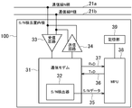
- FIG. 2 is a configuration diagram of the S / N detection indoor unit 100.
- the S / N detection indoor unit 100 includes a communication modem 31, a reception circuit 33, a transmission circuit 34, an MPU (microprocessor unit, also referred to as a microcomputer) 38, and a storage unit 39.
- the communication modem 31 has an S / N detector 32.
- a differential signal is used for the control communication of the air conditioning system 10, and the N-pole communication line 21a and the P-pole communication line 21b of the communication lines 21 are connected to the receiving circuit 33 and the transmitting circuit 34, respectively.
- the MPU 38 controls each part of the S / N detection indoor unit 100.
- the storage unit 39 stores programs and various data.
- the communication modem 31 controls communication with the outdoor unit 120 and the indoor unit 110.
- the S / N detector 32 detects and temporarily stores the received S / N for each communication packet.
- the MPU 38 exchanges RxD37 and TxD36 with and from the communication modem 31.
- the MPU 38 reads out the S / N data 35 temporarily stored in the S / N detector 32 for the packet whose group address of the demodulated packet matches its own group address.
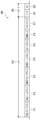
- FIG. 3 is a diagram showing a data configuration example of a communication packet used in the air conditioning system 10.
- the communication packet 300 includes a header 310 and a payload 320.
- the header 310 includes a destination group address 311 and a destination unit address 312, a source group address 313, a source unit address 314, a repeat counter 315, a modulation mode 316, and a payload size 317.
- the payload 320 contains data 321 and FCS 322.
- the destination group address and the destination unit address 312 store the destination group address and the unit address, respectively.
- the group address is the above-mentioned group ID.
- the source group address and the source unit address 314 store the source group address and the unit address.
- the repeat counter 315 can take a binary value of "1" indicating that the data is transferred and "0" indicating that the data is not transferred.
- the data size of the payload 320 is stored in the payload size 317.
- the data body is stored in the data 321. Additional data for error detection is stored in the FCS (frame check sequence) 322.
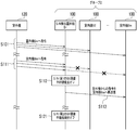
- FIG. 4 is a sequence diagram showing communication control processing by the air conditioning system 10.
- the processing between the outdoor unit 120 and the S / N detection indoor units B1 belonging to the group 2 and the indoor units B2 to Bm will be described, but between the outdoor unit 120 and the indoor units 100 and 110 of another group.
- the processing is the same.
- a case where the outdoor unit 120 transmits a communication packet addressed to the indoor unit Bm will be described.
- the S / N detection indoor unit B1 monitors the S / N of the communication packet designated as the destination group by its own device, and the communication packet having a low S / N is designated as the destination.
- a process of transferring a communication packet to the indoor unit 110 of the group is performed.
- the MPU 38 of the S / N detection indoor unit 100 constantly receives communication packets, and monitors whether or not the destination group address 311 of the header 310 matches the group ID of its own group. And.
- the outdoor unit 120 transmits a communication packet addressed to the indoor unit Bm.
- "Bm" is stored in the destination unit address 312, and "2" is stored in the destination group address 311. Therefore, the S / N detection indoor unit B1 monitors this communication packet as a communication packet addressed to its own group.
- the MPU 38 of the S / N detection indoor unit B1 reads out the S / N data temporarily stored in the S / N detector 32, and sets the value of the S / N data and the predetermined first S / N. Compare the thresholds (Th_L).
- the MPU 38 determines that the relay function is not turned on when the value of the S / N data is higher than the first S / N threshold value (Th_L). In this case, the MPU 38 does not perform the process related to the relay of the communication packet.
- the relay function is set to off in the initial state.
- the MPU 38 When the value of the S / N data is higher than the first S / N threshold value (Th_L), it can be inferred that stable communication is being performed. That is, for example, it is presumed that the communication packet addressed to the indoor unit Bm belonging to the same group is transmitted to the indoor unit Bm with sufficient S / N. Therefore, in this way, when the value of the S / N data is higher than the first S / N threshold value (Th_L), the MPU 38 does not perform the processing related to the relay.
- the outdoor unit 120 transmits a communication packet addressed to the indoor unit Bm, disturbances such as power supply noise and lightning surge occur.
- the S / N decreases and the value of the S / N data becomes less than the first S / N threshold value (Th_L).
- the MPU 38 of the S / N detection indoor unit B1 turns on the relay function (S112).
- the MPU 38 forwards (retransmissions) the received communication packet addressed to the indoor unit Bm (S113). That is, the MPU 38 relays the communication packet addressed to its own group. Since the devices in the same group are arranged in a narrow range and the communication distance is short, the reception S / N is high. Therefore, the indoor unit Bm can stably receive the communication packet.
- the MPU 38 changes the value of the repeat counter 315 of the transmitted communication packet from “0" to "1", makes the other values the same as the received communication packet, and sets the payload 320 as the received data. Enter the same value.
- the receiving device indoor unit Bm
- the receiving device can use the communication packet transmitted from the source identified by the source unit address 314 and the S / N. Communication packets transferred by the detection indoor unit B1 can be distinguished. That is, "1" of the repeat counter 316 is information indicating that the communication packet is retransmission data.
- the MPU 38 After the relay function is turned on, the MPU 38 compares the value of the S / N data with the predetermined second S / N threshold value (Th_H). Then, the MPU 38 turns off the relay function when the S / N becomes equal to or higher than the second S / N threshold value (Th_H) (S121). When the relay function is turned off, the MPU 38 ends the transfer of the communication packet. Then, the MPU 38 monitors the value of the S / N data after changing the comparison target from the second S / N threshold value (Th_H) to the first S / N threshold value (Th_L).
- FIG. 5 is an explanatory diagram of a first S / N threshold value (Th_L) and a second S / N threshold value (Th_L).
- the horizontal axis of the graph shown in FIG. 5 is time, and the vertical axis is S / N value.
- the second S / N threshold value (Th_H) is a higher value than the first S / N threshold value (Th_L). It is assumed that the first S / N threshold value (Th_L) and the second S / N threshold value (Th_H) are both preset.
- Curve 500 shows an example of S / N data.
- the relay function is turned on, and then when the S / N returns to a sufficient value, the relay function is turned off again.
- the S / N detection indoor unit 100 turns on the relay function as needed and turns off the relay function when it is not needed. As a result, it is possible to prevent unnecessary transfer while the sufficient S / N is obtained.
- stable communication can be realized by the S / N detection indoor unit 100 adaptively transferring (relaying) communication packets. Further, since the device in the same group as the relay destination is the relay source, the communication distance is short, and therefore stable transfer can be realized with a high S / N. Moreover, since a relay device is not separately provided, the cost of the entire system can be suppressed.
- the S / N detection indoor unit 100 receives an ACK indicating transfer completion from the transfer destination for the transferred communication packet, and if it does not receive the ACK, only a predetermined number of times. Retransmission (transfer) may be repeated. Specifically, when the indoor unit 110 receives the transfer packet, it returns ACK to the transfer source S / N detection indoor unit 100. Then, the S / N detection indoor unit 100 transmits the communication packet again after a certain period of time elapses without receiving the ACK after transmitting the communication packet. The S / N detection indoor unit 100 repeats this up to 3 times, for example.
- the S / N detection indoor unit 100 sets "3" in the repeat counter 315 of the transferred packet when the communication packet is first transferred, and sets the value of the repeat counter 315 to "3" each time the number of transfers increases. It may be reduced by 1 ”. In this way, the S / N detection indoor unit 100 may use the repeat counter 315 to manage the number of retransmissions.
- FIG. 6 is a configuration diagram of the S / N detection indoor unit 101 of the air conditioning system 11 according to the second embodiment.
- the S / N detection indoor unit 101 is used instead of the S / N detection air conditioner 100. That is, the S / N detection indoor unit 101 is used instead of the S / N detection indoor unit 100 as the S / N detection indoor units A1, B1, and C1 in FIG.
- the communication modem 31 has a modulator / demodulator 81 in addition to the S / N detector 32.
- the configuration and processing of the S / N detection air conditioner 101 are the same as the configuration and processing of the S / N detection air conditioner 100 described with reference to FIGS. 1 and 2 in the first embodiment.
- the MPU 38 of the S / N detection air conditioner 101 controls to perform modulation / demodulation at 16QAM (Quadrature Amplitude Modulation) when the relay function is off. Further, the MPU 38 controls to perform modulation / demodulation by BPSK (Binary Phase Shift Keying) when the relay function is on.
- 16QAM Quadrature Amplitude Modulation
- BPSK Binary Phase Shift Keying
- 16QAM is a modulation mode in which 4-bit modulation (4 bits / symbol) is performed in one modulation unit, and the S / N (required S / N) required for demodulation without error is 12 dB as an example.
- BPSK is a modulation mode in which 1 bit modulation (1 bit / symbol) is performed in 1 modulation unit, and the S / N (required S / N) required for demodulation without error is 3 dB as an example. That is, BPSK has a lower required S / N than 16QAM.
- FIG. 8 is a sequence diagram showing a communication control process by the air conditioning system 11 according to the second embodiment.
- the processing between the outdoor unit 120, the S / N detection indoor unit B1, and the indoor units B2 to Bm will be described with reference to FIG. 8, but the outdoor unit 120 and the indoor units 100 and 110 of other groups will be described. The process between and is the same.
- the outdoor unit 120 transmits a communication packet addressed to the indoor unit Bm.
- This processing is the same as the processing of S101 described with reference to FIG. 4, and in the MPU 38 of the S / N detection indoor unit B1, the value of the S / N data is higher than the first S / N threshold value (Th_L). Therefore, the processing related to the relay of the communication packet is not performed.
- the communication packet has a sufficient S / N and is transmitted to the indoor unit Bm.
- the MPU 38 of the S / N detection indoor unit B1 turns on the relay function (S212). Then, in S213, the MPU 38 transmits a modulation mode switching signal 82 to the modulator / demodulator 81 to change the modulation mode from 16QAM to BPSK. Further, the MPU 38 transmits a change request packet requesting the outdoor unit 120 to change the modulation mode of the packet addressed to the group “2” from 16QAM to BPSK and retransmit it.
- the outdoor unit 120 Upon receiving the change request packet, the outdoor unit 120 switches the modulation mode from 16QAM to BPSK in S214. Then, in S215, the outdoor unit 120 retransmits the communication packet transmitted in S211. At this time, the modulation mode is switched to BPSK with a low required S / N. Therefore, the indoor unit Bm can demodulate and receive the data even under disturbance noise.
- the MPU 38 While the relay function is on, BPSK communication is performed. Further, after the relay function is turned on, the MPU 38 compares the value of the S / N data with the second S / N threshold (Th_H). Then, the MPU 38 turns off the relay function when the S / N becomes equal to or higher than the second S / N threshold value (Th_H) (S221). Next, in S222, the MPU 38 transmits a modulation mode switching signal 82 to the modulator / demodulator 81 to change the modulation mode from BPSK to 16QAM. Further, the MPU 38 transmits a change request packet requesting the outdoor unit 120 to change the modulation mode of the packet addressed to the group "2" from BPSK to 16QAM. When the outdoor unit 120 transmits the change request packet, the modulation mode is switched from BPSK to 16QAM in S223.
- the indoor unit 100 at the transmission destination can surely obtain data.
- stable communication can be realized even in the air conditioning system 11 of the second embodiment.
- the air conditioning system 11 requires S / N when the value of the S / N data falls below the first S / N threshold value (Th_L).
- the modulation mode may be changed to a lower modulation mode, and the modulation mode change is not limited to 16QAM to BRSK.
- the air conditioning system 11 changes the modulation mode to change when the value of the S / N data falls below the first S / N threshold value (Th_L). It may be controlled to increase the transmission power from the outdoor unit 120. Specifically, the S / N detection air conditioner 101 transmits a request to increase the transmission power to the outdoor unit 120 when the value of the S / N data falls below the first S / N threshold value (Th_L). .. Then, when the outdoor unit 120 receives the request, the transmission power may be increased to retransmit the transmitted transmission packet.
- FIG. 9 is an overall view of the air conditioning system 12 according to the third embodiment.
- the air conditioning system 12 of the present embodiment has an S / N detection indoor unit 102 instead of the S / N detection indoor unit 100 described in the first embodiment. That is, the S / N detection indoor unit 101 is used as the S / N detection indoor unit A1, B1, and C1.
- FIG. 10 is a configuration diagram of the S / N detection indoor unit 102.
- the S / N detection indoor unit 102 has an outdoor unit side terminal 96a and an indoor unit side as a configuration on the P pole side of the communication line 21. It has a terminal 96b, an outdoor unit side SW94a, an indoor unit side SW94b, and a relay operation SW94c.
- the S / N detection indoor unit 102 includes an outdoor unit side terminal 97a, an indoor unit side terminal 97b, an outdoor unit side SW95a, an outdoor unit side SW95b, and a relay operation SW95c as a configuration on the N pole side. Have.
- the outdoor unit side terminal 96a is connected to the outdoor unit side P pole communication line 21f, which is the outdoor unit side P pole communication line.
- the indoor unit side terminal 96b is connected to the indoor unit side P pole communication line 21d, which is the outdoor unit side P pole communication line.
- the common terminal of the outdoor unit side SW94a is connected to the outdoor unit side terminal 96a.
- the common terminal of the indoor unit side SW94b is connected to the indoor unit side terminal 96b. In the state where the relay function is off, the outdoor unit side SW94a is tilted to the Y side, the indoor unit side SW94b is tilted to the X side, and the outdoor unit side terminal 96a and the indoor unit side terminal 96b are short-circuited.
- the relay operation SW94c is tilted to the Y side when the relay function is off, and is connected to the Y side of the outdoor unit side SW94a and the X side of the indoor unit side SW94b, and the common terminals are the receiving circuit 33 and the transmitting circuit. It is connected to 34.
- connection path between the outdoor unit side terminal 97a, the indoor unit side terminal 97b, the outdoor unit side SW95a, and the indoor unit side SW95b is the same as the P side of the above differential signal. Further, the connection path of the relay operation WSW95c is the same as that on the P side of the above differential signal.
- the S / N detection indoor unit 102 constantly demodulates the signal on the communication line 21 with the communication modem 31.
- a communication packet in which the outdoor unit 120 or the indoor unit 110 of another group is specified in the source unit address 314, and the indoor unit 110 belonging to the same group as the S / N detection indoor unit 102 is specified in the destination unit address 312.
- a communication packet in which a device in the own group is specified in the source unit address 314 and an indoor unit 110 or an outdoor unit 120 in another group is specified in the destination unit address 312 is a communication packet from the own group to another group or an outdoor unit. It is a communication packet to, and this is called an uplink packet.
- FIG. 11 is a flowchart showing the first communication control process of the S / N detection indoor unit 102 according to the third embodiment.
- the MPU 38 of the S / N detection indoor unit 102 determines whether or not the value of the S / N data of the downlink packet is smaller than the first S / N threshold value (Th_L).
- the MPU 38 advances the process to S302.
- the MPU 38 disconnects the communication lines 21f and 21e from the S / N detection indoor unit 102 on the outdoor unit side terminals 96a and 97a. Specifically, the MPU 38 tilts the outdoor unit side SW94a from the Y side in the initial state to the X side on the P side of the differential signal. Further, the MPU 38 tilts the outdoor unit side SW97a from the Y side in the initial state to the X side on the N side.
- the MPU 38 sets "1" in the repeat counter 315 of the communication packet.
- the MPU 38 transfers (relays) the same communication packet.
- the communication packet transferred from the indoor unit 110 is transmitted only to the indoor units belonging to the same group, and is not transmitted to the indoor units 100, 110 and the outdoor unit 120 of other groups. That is, it is possible to prevent an increase in communication network traffic due to forwarded packets. As a result, the efficiency of communication of the air conditioning system 10 as a whole can be improved.
- the MPU 38 After the processing of S304, in S305, the MPU 38 confirms whether or not ACK is received as a reply to the transferred communication packet. When the MPU 38 receives the ACK (YES in S305), the MPU 38 advances the process to S306. In S306, the MPU 38 returns the outdoor unit side SW94a from the X side to the Y side, assuming that the transfer has been completed. Similarly, the MPU 38 returns the outdoor unit side SW97a from the X side to the Y side. As a result, the communication lines 21f and 21e are connected to the S / N detection indoor unit SW102 on the outdoor unit side terminals 96a and 97a.
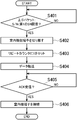
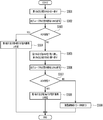
- FIG. 12 is a flowchart showing a second communication control process of the S / N detection indoor unit 102 according to the third embodiment.
- the MPU 38 of the S / N detection indoor unit 102 determines whether or not the value of the S / N data of the uplink packet is smaller than the first S / N threshold value (Th_L).
- the MPU 38 advances the process to S402.
- the MPU 38 disconnects the communication lines 21d and 21c from the indoor unit side terminals 96b and 97b and the S / N detection indoor unit 102. Specifically, the MPU 38 tilts the indoor unit side SW94b from the X side to the Y side in the initial state on the P side of the differential signal. Similarly, the MPU 38 tilts the indoor unit side SW95b from the X side to the Y side in the initial state with respect to the N side of the differential signal.
- the MPU 38 sets "1" in the repeat counter 315 of the communication packet.
- the MPU 38 transfers (relays) the same communication packet.
- the communication packet transmitted in this way is transmitted to the indoor units 100 and 110 of a group different from the outdoor unit 120 and the S / N detection indoor unit 100, and is not transmitted to the indoor units 100 and 110 of the same group.
- the MPU 38 After the processing of S404, in S405, the MPU 38 confirms whether or not ACK is received as a reply to the transferred communication packet. When the MPU 38 receives the ACK (YES in S405), the MPU 38 advances the process to S406. In S406, the MPU 38 returns the indoor unit side SW94b from the Y side to the X side, assuming that the transfer has been completed. Similarly, the MPU 38 tilts the indoor unit side SW95b from the Y side to the X side. As a result, the communication lines 21d and 21c and the S / N detection indoor unit SW102 are connected to the indoor unit side terminals 96b and 97b.
- the outdoor unit 120 In both the first communication control process and the second communication control process, the outdoor unit 120, while the communication line 21 and the S / N detection indoor unit 102 are separated and the communication packet is transferred. There may be communication packets transmitted from other indoor units 100 and 110. When the S / N detection indoor unit 102 receives these communication packets, it temporarily stores them in the storage unit 039. Then, when the communication line 21 is connected again, the S / N detection indoor unit 102 transmits the communication packet stored in the storage unit 039.
- the P-pole communication line 21f of the differential signal is connected to the P-pole communication line 21d of the differential signal
- the N-pole communication line 21e of the differential signal is connected to the N-pole communication line 21c of the differential signal.
- a differential signal having a non-polar wiring polarity is often used, and a communication method regardless of the polarity may be used.
- the construction worker connects the outdoor unit side communication lines 21f and 21e to the outdoor unit side terminal 96a and the outdoor unit side terminal 97a, respectively, and the indoor unit side.
- the communication lines 21d and 21c are connected to the terminals 96b and 97b, respectively.
- the wiring automatic determination process is performed.
- FIG. 13 is a flowchart showing the wiring automatic determination process by the S / N detection indoor unit 102.
- the terminals 96a and 96b are short-circuited, and the terminals 97a and 97b are short-circuited.
- the terminals 96a, 96b, 97a, 97b will be referred to as a first terminal 96a, a second terminal 96b, a third terminal 97a, and a fourth terminal 97b.
- SW94a, 94b, 95a and 96b will be referred to as a first SW94a, a second SW94b, a third SW95a and a fourth SW95b, respectively.
- the MPU 38 of the S / N detection indoor unit 102 tilts the first SW94a and the third SW95a to the X side. As a result, the first terminal 96a and the third terminal 97a side are separated.
- the MPU 38 transmits ENQ, which is an inquiry signal, to the indoor unit of its own group. For example, when the S / N detection indoor unit B1 shown in FIG. 9 performs this processing, the EMQ is transmitted to the indoor unit B2 or the like of the group 2.
- the MPU 38 determines whether or not ACK has been received from the destination indoor unit.
- the MPU 38 advances the process to S504. If the MPU 38 does not receive the ACK (NO in S504), the MPU 38 proceeds to the process in S505.
- the MPU 38 determines that the second terminal 96b and the fourth terminal 97b are terminals on the indoor unit side. This completes the wiring automatic determination process.
- the MPU 38 tilts the second SW94b and the fourth SW95b to the Y side, and further tilts the first SW94a and the third SW95a to the Y side. As a result, the second terminal 96b and the fourth terminal 97b side are separated.
- the MPU 38 transmits an ENQ to the indoor unit of its own group.
- the MPU 38 determines whether or not an ACK has been received from the destination indoor unit. When the MPU 38 receives the ACK (YES in S507), the MPU 38 advances the process to S508. If the MPU 38 does not receive the ACK (NO in S507), the MPU 38 proceeds to the process in S509.
- the MPU 38 determines that the first terminal 96a and the third terminal 97a are terminals on the indoor unit side. This completes the wiring automatic determination process.
- the MPU 38 determines that the communication line 21 is erroneously wired to the S / N detection indoor unit with a built-in SW, and displays "communication line connection error" or the like on the indoor unit remote controller (not shown). Prompt the worker to confirm the connection. This completes the automatic delivery determination process.
- the wiring of the S / N detection indoor unit 102 is confirmed by the worker in the automatic distribution determination process. As a result, human error in wiring can be reduced.
- FIG. 14 is a configuration diagram of the S / N detection air conditioner 103 of the air conditioning system 13 according to the fourth embodiment.
- the S / N detection indoor unit 103 is used instead of the S / N detection air conditioner 100. That is, the S / N detection indoor unit 103 is used instead of the S / N detection indoor unit 100 as the S / N detection indoor units A1, B1, and C1 in FIG.
- the S / N detection indoor unit 103 is connected to an AC100V power supply line, superimposes a control communication signal on the power supply line, and communicates with the outdoor unit 120 and other indoor units 103, 110, and the like.
- the power supply R terminal 55a and the power supply S terminal 55b are connected to the power supply line 22a and the power supply line 22b, respectively.
- the power lines 22a and 22b are non-polar. Generally, a three-core wire is used as the power supply for the air conditioner, and a signal called a common line 22c is connected to the power supply circuit 52 together with the power supply line.
- the communication modem 31 transmits and receives a radio frequency band carrier wave significantly higher than the power supply frequency by 16QAM or BPSK modulation, limits the band by the high frequency pass filter 103, and superimposes it on AC100V by the superimposition circuit 104 for communication.
- the air conditioning system 13 may perform communication by superimposing it on the power supply line instead of using the dedicated communication line for air conditioning control.
- packets can be relayed without using a dedicated relay device, and the relay can always be transferred by the S / N detection indoor unit 103, which has a short communication distance, and is stable at a high S / N.
- a receivable air conditioning system can be realized.
Landscapes
- Engineering & Computer Science (AREA)
- Computer Networks & Wireless Communication (AREA)
- Signal Processing (AREA)
- Human Computer Interaction (AREA)
- Chemical & Material Sciences (AREA)
- Combustion & Propulsion (AREA)
- Mechanical Engineering (AREA)
- General Engineering & Computer Science (AREA)
- Air Conditioning Control Device (AREA)
Abstract
S/N検出室内機は、通信手段と、S/N検出室内機と同一のグループに属する同グループ室内機を宛先とするデータのS/Nを検出する検出器とを有する。通信手段は、S/Nが第1の閾値未満の場合に、データを再送する。
Description
本発明は、空気調和システム及び空気調和システムにおける通信方法に関する。
従来、ビル用空気調和システムの制御通信方式は、一般に総接続台数200台以上、通信ケーブルの総距離1000m以上という仕様であり、その通信網トポロジーは、設置時の工事作業性を優先するため、分岐数に制限のない、渡り配線という自由な接続を許可している。
空気調和システムの設置後はビル内で発生する電源ノイズや、室外機通信ケーブルが屋外であるための雷サージによる通信不能が発生し得る。また、設備耐用年数が長期に渡ることによる通信ケーブルの経時劣化による通信不能も発生し得る。これに対し、特許文献1には、通信経路の途中に信号中継装置を挿入して、制御通信の安定性を維持する技術が開示されている。また、特許文献2には、中継装置が設置された通信網内の位置に応じて、中継する際に用いる信号波高値の閾値を、個別に設定する信号中継装置が開示されている。
通信品質を保つために、特許文献1に示すように、室内機及び室外機に加えて、中継装置を設置することも考えられるが、空気調和システム全体のコストが増加するという問題があった。
本発明はこのような問題点に鑑みなされたもので、空気調和システム全体コストを抑えつつ、安定した通信を実現することを目的とする。
そこで、本発明は、空気調和システムであって、室外機と、S/N検出機能を有するS/N検出室内機を含む複数の室内機とを有し、前記S/N検出室内機は、通信手段と、前記S/N検出室内機と同一のグループに属する同グループ室内機を宛先とするデータのS/Nを検出する検出器とを有し、前記通信手段は、前記S/Nが第1の閾値未満の場合に、前記データを再送することを特徴とする。
本発明の他の形態は、空気調和システムであって、室外機と、S/N検出機能を有するS/N検出室内機を含む複数の室内機とを有し、前記S/N検出室内機は、通信手段と、前記S/N検出室内機と同一のグループに属する同グループ室内機宛てのパケットのS/Nを検出する検出器とを有し、前記通信手段は、前記S/Nが第1の閾値未満の場合に、前記パケットの送信元に対し、処理時点において設定されている変調方式に比べて所要S/Nの低い変調方式への変更指示を送信することを特徴とする。
本発明によれば、空気調和システム全体コストを抑えつつ、安定した通信を実現することができる。
(第1の実施形態)
図1は、第1の実施形態に係る空気調和システムを示す図である。空気調和システム10は、室外機120と、複数台のS/N検出室内機100と、複数台の室内機110と、を有している、ここで、S/N検出室内機100は、室内機110と同様の構成に加えて、後述のS/N検出器を備えている。なお、適宜、S/N検出室内機100と室内機110をまとめて室内機100、110と称するものとする。
図1は、第1の実施形態に係る空気調和システムを示す図である。空気調和システム10は、室外機120と、複数台のS/N検出室内機100と、複数台の室内機110と、を有している、ここで、S/N検出室内機100は、室内機110と同様の構成に加えて、後述のS/N検出器を備えている。なお、適宜、S/N検出室内機100と室内機110をまとめて室内機100、110と称するものとする。
図1に示すように、本実施形態の空気調和システム10は、1つのビルに設置され、室内機110が各階に複数台ずつ設置されているものとする。本実施形態においては、各階に複数台の室内機110が設置されているものとする。各階に設置される室内機110の台数は特に限定されないが、例えば、数十台とする。図1においては、地下1階、地上1階、2階のS/N検出室内機、室内機を示しているが、実際には、3階以上においても、同様にS/N検出室内機及び室内機が設置されているものとする。なお、空気調和システム10は、室内機100が200台以上の大規模なシステムであってもよい。
空気調和システム10では、近接する室内機100をグループ化して制御する。本実施形態においては、空気調和システム10は、階毎に室内機100をグループ化して制御するものとする。さらに、各グループに1台のS/N検出室内機100が配置されるようにする。すなわち、S/N検出室内機100が各階に1台ずつ設置される。いずれのグループにおいても、室外機120からの通信線21の距離が最短となる位置にS/N検出室内機100が設置されるものとする。
具体的には、地下1階のS/N検出室内機100及び室内機110には、グループID1が割り当てられている。また、1階のS/N検出室内機100及び室内機110にはグループID2が割り当てられ、2階のS/N検出室内機100及び室内機110にはグループID3が割り当てられている。
なお、本実施形態においては、階ごとのグループを例に説明するが、グループの決め方は実施形態に限定されるものではない。他の例としては、同一階において、設置場所に応じた複数のグループが設定されてもよい。
さらに、各S/N検出室内機100及び各室内機110は、通信線21を介して室外機120と接続している。本実施形態においては、室外機120に接続された通信線21は、途中で分岐し、各階のS/N検出室内機100と接続している。さらに、通信線21は、S/N検出室内機100を経由し、その後複数の室内機110に順番に接続する。すなわち、S/N検出室内機100は、スター型の配線で室外機120に接続し、室内機110は、デイジーチェーン型の配線で室外機120に接続する。
本実施形態においては、地下1階のS/N検出室内機100のユニットアドレスはA1であるものとし、このS/N検出室内機100を適宜、S/N検出室内機A1と称することとする。また、地下1階の複数の室内機110のユニットアドレスはS/N検出室内機A1に近い順にA2、…Amであるものとし、対応する室内機110を適宜、室内機A2、…室内機Amと称することとする。
同様に、1階のS/N検出室内機100のユニットアドレスはB1であり、このS/N検出室内機100を適宜、S/N検出室内機B1と称する。また、1階の室内機110のユニットアドレスはS/N検出室内機B1に近い順に、B2、…Bmであるものとし、対応する室内機110を適宜室内機B2、…室内機Bmと称することとする。
2階のS/N検出室内機100のユニットアドレスはC1であり、このS/N検出室内機100を適宜、S/N検出室内機C1と称する。また、2階の室内機110のユニットアドレスはS/N検出室内機C1に近い順に、C2、…Cmであるものとし、対応する室内機110を適宜、室内機C2、…室内機Cmと称することとする。
室外機120は、制御コマンドを含む通信パケットを室内機100、110へ送信する。室内機100、110は、室外機120への応答や温度データを含む通信パケットを室外機120へ送信する。また、室内機100、110の間でも通信パケットの送受信が可能である。
図2は、S/N検出室内機100の構成図である。S/N検出室内機100は、通信モデム31と、受信回路33と、送信回路34と、MPU(マイクロプロセッサユニット、マイコンとも呼ぶ)38と、記憶部39と、を有している。通信モデム31は、S/N検出器32を有している。空気調和システム10の制御通信には差動信号が用いられ、通信線21のうちN極通信線21a及びP極通信線21bはそれぞれ受信回路33及び送信回路34に接続している。MPU38は、S/N検出室内機100の各部を制御する。記憶部39は、プログラムや各種データを記憶する。通信モデム31は、室外機120及び室内機110との通信を制御する。S/N検出器32は、通信パケット毎に、受信S/Nを検出して一時記憶する。MPU38は、通信モデム31との間でRxD37及びTxD36の授受を行う。MPU38は、復調されたパケットのグループアドレスが自らのグループアドレスと一致したパケットについては、S/N検出器32に一時記憶されているS/Nデータ35を読み出す。
図3は、空気調和システム10において用いられる通信パケットのデータ構成例を示す図である。通信パケット300には、ヘッダー310と、ペイロード320と、が含まれている。ヘッダー310には、宛先グループアドレス311と、宛先ユニットアドレス312と、発信元グループアドレス313と、発信元ユニットアドレス314と、リピートカウンタ315と、変調モード316と、ペイロードサイズ317と、が含まれている。ペイロード320には、データ321と、FCS322と、が含まれている。
宛先グループアドレス311及び宛先ユニットアドレス312には、それぞれ宛先のグループアドレス及びユニットアドレスが格納される。ここで、グループアドレスは上述のグループIDである。発信元グループアドレス313及び発信元ユニットアドレス314には、発信元のグループアドレス及びユニットアドレスが格納される。
リピートカウンタ315には、本通信パケット300が転送データであるか否かを示す情報が格納される。リピートカウンタ315は、転送データであることを示す「1」と転送データでないことを示す「0」の二値を取り得る。ペイロードサイズ317には、ペイロード320のデータサイズが格納される。データ321には、データ本体が格納される。FCS(フレームチェックシーケンス)322には、誤り検出のための付加データが格納される。
図4は、空気調和システム10による通信制御処理を示すシーケンス図である。ここでは、室外機120とグループ2に属するS/N検出室内機B1、室内機B2~Bmの間の処理について説明するが、室外機120と他のグループの室内機100、110との間の処理も同様である。ここでは、室外機120が室内機Bm宛ての通信パケットを送信するケースについて説明する。通信制御処理において、S/N検出室内機B1は、自装置が宛先グループとして指定される通信パケットのS/Nを監視し、S/Nが低い通信パケットについては、宛先として指定された、同グループの室内機110に通信パケットを転送する処理を行う。
まず、前提として、S/N検出室内機100のMPU38は、常時通信パケットを受信しており、ヘッダー310の宛先グループアドレス311が自グループのグループIDと一致するか否かを監視しているものとする。
S101において、室外機120が室内機Bm宛ての通信パケットを送信する。なお、この通信パケットは、宛先ユニットアドレス312に「Bm」が格納され、宛先グループアドレス311に「2」が格納されている。このため、S/N検出室内機B1は、本通信パケットを自グループ宛て通信パケットとして監視する。そして、S/N検出室内機B1のMPU38は、S/N検出器32に一時記憶されているS/Nデータを読み出し、S/Nデータの値と、予め定められた第1のS/N閾値(Th_L)を比較する。MPU38は、S/Nデータの値が第1のS/N閾値(Th_L)より高い場合、中継機能をオンしないと判断する。この場合、MPU38は、通信パケットの中継に係る処理は行わない。なお、S/N検出室内機B1において、初期状態においては、中継機能はオフに設定されているものとする。
S/Nデータの値が第1のS/N閾値(Th_L)よりも高い場合には、安定した通信が行われていると推測できる。すなわち、例えば同グループに属する室内機Bm宛ての通信パケットは十分なS/Nで室内機Bmに送信されていると推測される。そこで、このように、MPU38は、S/Nデータの値が第1のS/N閾値(Th_L)より高い場合には、中継に係る処理は行わないものとする。
一方で、S111において、室外機120が室内機Bm宛ての通信パケットを送信した際に、電源ノイズや雷サージ等の外乱が発生していたとする。この場合、S/Nが低下し、S/Nデータの値は第1のS/N閾値(Th_L)未満となる。このように、S/Nデータの値が第1のS/N閾値(Th_L)未満の場合には、S/N検出室内機B1のMPU38は、中継機能をオンにする(S112)。そして、MPU38は、中継機能がオンの状態においては、受信した室内機Bm宛ての通信パケットを転送(再送)する(S113)。すなわち、MPU38は、自グループ宛ての通信パケットを中継する。同一グループ内の機器は、狭い範囲に配置されており、通信距離が短いため、受信S/Nは高い。したがって、室内機Bmは、安定して通信パケットを受信することができる。
なお、この場合、MPU38は、送信する通信パケットのリピートカウンタ315の値を「0」から「1」へ変更し、他は、受信した通信パケットと同じ値とし、ペイロード320には受信したデータと同じ値を入れる。このように、リピートカウンタ316の値を「1」とすることで、受信した装置(室内機Bm)は、発信元ユニットアドレス314で識別される送信元から送信された通信パケットと、S/N検出室内機B1により転送された通信パケットを区別できる。すなわち、リピートカウンタ316の「1」は、通信パケットが再送データであることを示す情報である。
中継機能がオンになった後は、MPU38は、S/Nデータの値と、予め定められた第2のS/N閾値(Th_H)を比較する。そして、MPU38は、S/Nが第2のS/N閾値(Th_H)以上になると、中継機能をオフする(S121)。MPU38は、中継機能がオフになると、通信パケットの転送を終了する。そして、MPU38は、比較対象を第2のS/N閾値(Th_H)から第1のS/N閾値(Th_L)に変更した上で、S/Nデータの値を監視する。
図5は、第1のS/N閾値(Th_L)及び第2のS/N閾値(Th_L)の説明図である。図5に示すグラフの横軸は時間、縦軸はS/Nの値を示している。図5に示すように、第2のS/N閾値(Th_H)は、第1のS/N閾値(Th_L)に比べて高い値である。なお、第1のS/N閾値(Th_L)及び第2のS/N閾値(Th_H)は、いずれも予め設定されているものとする。
このように、ヒステリシスに応じた閾値を定めることにより、MPU38は、中継機能のオンオフを適切に行うことができる。曲線500は、S/Nデータの一例を示している。このように、外乱等により一時的にS/Nが低くなった場合には、中継機能をオンにし、その後、S/Nが十分な値に戻った場合には、再度中継機能をオフする。このように、S/N検出室内機100は、必要に応じて中継機能をオンし、不要な場合には中継機能をオフする。これにより、十分なS/Nが得られている間は、無駄に転送を行わないようにすることができる。
以上のように、本実施形態に係る空気調和システム10においては、S/N検出室内機100が適応的に通信パケットの転送(中継)を行うことで、安定した通信を実現することができる。さらに、中継先と同一グループ内の機器が中継元になるため、通信距離が短く、したがって、高いS/Nで安定した転送を実現することができる。また、別途中継装置を設けることがないため、システム全体のコストを抑えることができる。
実施形態の変形例としては、S/N検出室内機100は、転送した通信パケットに対し、転送先から転送完了を示すACKを受信することとし、ACKを受信しない場合には、所定の回数だけ再送(転送)を繰り返すこととしてもよい。具体的には、室内機110は、転送パケットを受信した場合には、転送元のS/N検出室内機100にACKを返すこととする。そして、S/N検出室内機100は、通信パケットの送信後ACKを受信しない状態で一定時間が経過すると、再度通信パケットを送信する。S/N検出室内機100は、例えばこれを3回まで繰り返すこととする。この場合、S/N検出室内機100は、最初に通信パケットの転送を行う際に、転送パケットのリピートカウンタ315に「3」を設定し、転送回数が増える毎にリピートカウンタ315の値を「1」ずつ減じるようにしてもよい。このように、S/N検出室内機100は、リピートカウンタ315を再送の回数を管理するために利用してもよい。
(第2の実施形態)
次に、第2の実施形態に係る空気調和システムについて、第1の実施形態に係る空気調和システム10と異なる点を主に説明する。図6は、第2の実施形態に係る空気調和システム11のS/N検出室内機101の構成図である。第2の実施形態においては、S/N検出空調機100に替えて、S/N検出室内機101が用いられる。すなわち、図1におけるS/N検出室内機A1、B1、C1としてS/N検出室内機100にかえて、S/N検出室内機101が用いられる。
次に、第2の実施形態に係る空気調和システムについて、第1の実施形態に係る空気調和システム10と異なる点を主に説明する。図6は、第2の実施形態に係る空気調和システム11のS/N検出室内機101の構成図である。第2の実施形態においては、S/N検出空調機100に替えて、S/N検出室内機101が用いられる。すなわち、図1におけるS/N検出室内機A1、B1、C1としてS/N検出室内機100にかえて、S/N検出室内機101が用いられる。
第2の実施形態に係るS/N検出空調機101においては、通信モデム31は、S/N検出器32に加えて、変復調器81を有している。これ以外のS/N検出空調機101の構成及び処理は、第1の実施形態において図1、図2を参照しつつ説明したS/N検出空調機100の構成及び処理と同様である。
S/N検出空調機101のMPU38は、図7に示すように、中継機能がオフの状態においては、16QAM(Quadrature Amplitude Modulation)で変復調を行うよう制御する。また、MPU38は、中継機能がオンの状態においては、BPSK(Binary Phase Shift Keying)で変復調を行うよう制御する。
16QAMは1変調単位に4ビット変調(4ビット/シンボル)する変調モードであり、誤り無く復調するために必要なS/N(所要S/N)は、一例として12dBである。一方、BPSKは1変調単位に1ビット変調(1ビット/シンボル)する変調モードであり、誤り無く復調するために必要なS/N(所要S/N)は、一例として3dBである。すなわち、BPSKは、16QAMに比べて所要S/Nが低い。
図8は、第2の実施形態に係る空気調和システム11による通信制御処理を示すシーケンス図である。ここでは、図8を参照しつつ、室外機120と、S/N検出室内機B1、室内機B2~Bmの間の処理について説明するが、室外機120と他のグループの室内機100、110との間の処理も同様である。
S201において、室外機120が室内機Bm宛ての通信パケットを送信する。本処理は、図4を参照しつつ説明したS101の処理と同様であり、S/N検出室内機B1のMPU38は、S/Nデータの値が第1のS/N閾値(Th_L)より高いと判断し、通信パケットの中継に係る処理は行わない。なお、通信パケットは、十分なS/Nであり、室内機Bmに送信される。
一方で、S211において、室外機120が室内機Bm宛ての通信パケットを送信した際、外乱が発生しており、S/Nデータの値が第1のS/N閾値(Th_L)未満になったとする。この場合、S/N検出室内機B1のMPU38は、中継機能をオンにする(S212)。そして、S213において、MPU38は、変復調器81に対し変調モード切替信号82を送信し、変調モードを16QAMからBPSKへ変更する。さらに、MPU38は、室外機120に対し、グループ「2」宛てのパケットの変調モードを16QAMからBPSKへ変更して再送するように要求する変更要求パケットを送信する。
室外機120は、変更要求パケットを受信すると、S214において、変調モードを16QAMからBPSKに切り替える。そして、S215において、室外機120は、S211において送信した通信パケットを再び送信する。このとき変調モードは、所要S/Nの低いBPSKに切り替えられている。したがって、室内機Bmは、外乱雑音下においても、復調してデータを受信することができる。
中継機能がオンの間は、BPSKでの通信が行われる。さらに、中継機能がオンになった後は、MPU38は、S/Nデータの値と第2のS/N閾値(Th_H)を比較する。そして、MPU38は、S/Nが第2のS/N閾値(Th_H)以上になると、中継機能をオフする(S221)。次に、S222において、MPU38は、変復調機81に対し変調モード切替信号82を送信し、変調モードをBPSKから16QAMに変更する。さらに、MPU38は、室外機120に対し、グループ「2」宛てのパケットの変調モードをBPSKから16QAMへ変更するように要求する変更要求パケットを送信する。室外機120は、変更要求パケットを送信すると、S223において、変調モードをBPSKから16QAMに切り替える。
以上のように、第2の実施形態に係る空気調和システム11においては、S/N検出室内機101が検出したS/Nデータの値が第1のS/N閾値(Th_L)を下回った場合には、変調モードを16QAMから所要S/Nのより低いBPSKに変更する。これにより、送信先の室内機100は確実にデータを得ることができる。このように、第2の実施形態の空気調和システム11においても、安定した通信を実現することができる。
なお、第2の実施形態の第1の変形例としては、空気調和システム11は、S/Nデータの値が第1のS/N閾値(Th_L)を下回った場合に、所要S/Nのより低い変調モードに変更すればよく、変調モードの変更は、16QAMからBRSKに限定されるものではない。
また、第2の変形例としては、空気調和システム11は、S/Nデータの値が第1のS/N閾値(Th_L)を下回った場合には、変調モードを変更するのに変えて、室外機120からの送信電力を上げるように制御してもよい。具体的には、S/N検出空調機101は、S/Nデータの値が第1のS/N閾値(Th_L)を下回った場合には、送信電力を上げる要求を室外機120に送信する。そして、室外機120は、要求を受信すると、送信電力を上げて、送信済みの送信パケットの再送を行えばよい。
(第3の実施形態)
次に、第3の実施形態に係る空気調和システムについて、他の実施形態に係る空気調和システムと異なる点を主に説明する。図9は、第3の実施形態に係る空気調和システム12の全体図である。本実施形態の空気調和システム12は、第1の実施形態において説明したS/N検出室内機100に替えて、S/N検出室内機102を有している。すなわち、S/N検出室内機A1、B1、C1として、S/N検出室内機101が用いられる。
次に、第3の実施形態に係る空気調和システムについて、他の実施形態に係る空気調和システムと異なる点を主に説明する。図9は、第3の実施形態に係る空気調和システム12の全体図である。本実施形態の空気調和システム12は、第1の実施形態において説明したS/N検出室内機100に替えて、S/N検出室内機102を有している。すなわち、S/N検出室内機A1、B1、C1として、S/N検出室内機101が用いられる。
図10は、S/N検出室内機102の構成図である。S/N検出室内機102は、第1の実施形態に係るS/N検出室内機100の構成に加えて、通信線21のP極側の構成として、室外機側端子96aと、室内機側端子96bと、室外機側SW94aと、室内機側SW94bと、中継動作SW94cと、を有している。さらに、S/N検出室内機102は、N極側の構成として、室外機側端子97aと、室内機側端子97bと、室外機側SW95aと、室外機側SW95bと、中継動作SW95cと、を有している。
室外機側端子96aは、室外機側のP極通信線である、室外機側P極通信線21fと接続している。室内機側端子96bは、室外機側のP極通信線である、室内機側P極通信線21dと接続している。室外機側SW94aのコモン端子は、室外機側端子96aと接続している。室内機側SW94bのコモン端子は、室内機側端子96bと接続している。中継機能がオフの状態においては、室外機側SW94aは、Y側に倒れ、室内機側SW94bはX側に倒れて、室外機側端子96aと室内機側端子96bとを短絡している。また、中継動作SW94cは、中継機能がオフの状態においては、Y側に倒れて、室外機側SW94aのY側と室内機側SW94bのX側に接続され、コモン端子は受信回路33と送信回路34に接続されている。
室外機側端子97aと、室内機側端子97bと、室外機側SW95aと、室内機側SW95bとの接続経路は上記の差動信号のP側と同様である。また、中継動作WSW95cの接続経路も上記の差動信号のP側と同様である。
S/N検出室内機102は、常時、通信線21上の信号を通信モデム31で復調している。ここで、発信元ユニットアドレス314に室外機120又は他グループの室内機110が指定され、かつ宛先ユニットアドレス312にS/N検出室内機102と同一グループに属する室内機110が指定された通信パケットは、自グループ内への機器への通信パケットであり、これを下りパケットと称する。一方、発信元ユニットアドレス314に自グループ内の機器が指定され、かつ宛先ユニットアドレス312に他グループの室内機110又は室外機120が指定された通信パケットは、自グループ内から他グループ又は室外機への通信パケットであり、これを上りパケットと称する。
図11は、第3の実施形態に係るS/N検出室内機102の第1の通信制御処理を示すフローチャートである。S301において、S/N検出室内機102のMPU38は、下りパケットのS/Nデータの値が第1のS/N閾値(Th_L)よりも小さいか否かを判定する。MPU38は、下りパケットのS/Nデータの値が第1のS/N閾値(Th_L)よりも小さい場合には(S301でYES)、処理をS302へ進める。
S302において、MPU38は、室外機側端子96a、97a側において通信線21f、21eとS/N検出室内機102とを切り離す。具体的には、MPU38は、差動信号のP側について、室外機側SW94aを初期状態のY側からX側へ倒す。さらに、MPU38は、N側について、室外機側SW97aを初期状態のY側からX側へ倒す。次に、S303において、MPU38は、通信パケットのリピートカウンタ315に「1」を設定する。次に、S304において、MPU38は、同じ通信パケットの転送(中継)を行う。
これにより、室内機110から転送された通信パケットは、同一グループに属する室内機のみに送信され、他のグループの室内機100、110、室外機120へは送信されない。すなわち、転送パケットによる通信網トラヒックの増加を防ぐことができる。これにより、空気調和システム10の全体としての通信の効率化を図ることができる。
S304の処理の後、S305において、MPU38は、転送した通信パケットに対する返信としてACKを受信したか否かを確認する。MPU38は、ACKを受信すると(S305でYES)、処理をS306へ進める。S306においては、MPU38は、転送が完了したものとして、室外機側SW94aをX側からY側に戻す。同様に、MPU38は、室外機側SW97aをX側からY側に戻す。これにより、室外機側端子96a、97a側において、通信線21f、21eとS/N検出室内機SW102とが接続される。
図12は、第3の実施形態に係るS/N検出室内機102の第2の通信制御処理を示すフローチャートである。S401において、S/N検出室内機102のMPU38は、上りパケットのS/Nデータの値が第1のS/N閾値(Th_L)よりも小さいか否かを判定する。MPU38は、上りパケットのS/Nデータの値が第1のS/N閾値(Th_L)よりも小さい場合には(S401でYES)、処理をS402へ進める。
S402において、MPU38は、室内機側端子96b、97b側において通信線21d、21cとS/N検出室内機102とを切り離す。具体的には、MPU38は、差動信号のP側について、室内機側SW94bを初期状態のX側からY側へ倒す。同様に、MPU38は、差動信号のN側について、室内機側SW95bを初期状態のX側からY側へ倒す。
次に、S403において、MPU38は、通信パケットのリピートカウンタ315に「1」を設定する。次に、S404において、MPU38は、同じ通信パケットの転送(中継)を行う。こうして送信された通信パケットは、室外機120及びS/N検出室内機100と異なるグループの室内機100、110に送信され、同一グループの室内機100、110には送信されない。これにより、転送パケットによる通信網トラヒックの増加を防ぐことができ、空気調和システム10の全体としての通信の効率化を図ることができる。
S404の処理の後、S405において、MPU38は、転送した通信パケットに対する返信としてACKを受信したか否かを確認する。MPU38は、ACKを受信すると(S405でYES)、処理をS406へ進める。S406においては、MPU38は、転送が完了したものとして、室内機側SW94bをY側からX側に戻す。同様に、MPU38は、室内機側SW95bをY側からX側へ倒す。これにより、室内機側端子96b、97b側において、通信線21d、21cとS/N検出室内機SW102とが接続される。
なお、第1の通信制御処理及び第2の通信制御処理のいずれにおいても、通信線21とS/N検出室内機102とを切り離し、通信パケットの転送を行っている間に、室外機120、他の室内機100、110から送信される通信パケットが存在する場合がある。S/N検出室内機102は、これらの通信パケットを受信すると、これを記憶部039に一時的に格納しておく。そして、再び通信線21が接続された場合に、S/N検出室内機102が記憶部039に格納された通信パケットを送信する。
なお上記説明では、差動信号のP極通信線21fが差動信号のP極通信線21dへ繋がり、差動信号のN極通信線21eが差動信号のN極通信線21cへ繋がるものとして説明した、ただし、空気調和システム制御に係る通信方式は、配線極性が無極性である差動信号を用いる場合が多く、極性を問わない通信方式を用いてもよい。
次に、S/N検出室内機102の設置工事時の処理について説明する。通信線21をS/N検出室内機102に接続する設置工事においては、工事作業者が、室外機側通信線21f、21eを各々室外機側端子96a及び室外機側端子97aへ、室内機側通信線21d、21cを各々端子96b、97bへ接続する。この方法を用いた場合、人的ミスにより誤配線となる可能性がある。これに対し、本実施形態に係る空気調和システム12においては、配線自動判定処理を行う。
図13は、S/N検出室内機102による、配線自動判定処理を示すフローチャートである。なお、配線自動判定処理の実行前の状態においては、端子96a、96bが短絡され、かつ端子97a、97bが短絡されている。但し、端子96a、97aと、端子96b、97bのどちらが室外機側で、どちらが室内機側かは分からないものとする。以下においては、端子96a、96b、97a、97bを第1端子96a、第2端子96b、第3端子97a、第4端子97bと称することとする。また、SW94a、94b、95a、96bをそれぞれ第1SW94a、第2SW94b、第3SW95a、第4SW95bと称することとする。
まず、S501において、S/N検出室内機102のMPU38は、第1SW94a及び第3SW95aをX側へ倒す。これにより、第1端子96a及び第3端子97a側を切り離す。次に、S502において、MPU38は、自グループの室内機宛てに、問合せ信号であるENQを送信する。例えば、図9に示すS/N検出室内機B1が本処理を行う場合には、グループ2の室内機B2等にEMQを送信する。
次に、S503において、MPU38は、送信先の室内機からACKを受信したか否かを判定する。MPU38は、ACKを受信した場合には(S504でYES)、処理をS504へ進める。MPU38は、ACKを受信しなかった場合には(S504でNO)、処理をS505へ進める。S504において、MPU38は、第2端子96b及び第4端子97bが室内機側の端子であると判定する。以上で、配線自動判定処理が終了する。
また、S505において、MPU38は、第2SW94b及び第4SW95bをY側へ倒し、さらに第1SW94a及び第3SW95aをY側へ倒す。これにより、第2端子96b及び第4端子97b側を切り離す。次に、S506において、MPU38は、自グループの室内機宛てに、ENQを送信する。次に、S507において、MPU38は、送信先の室内機からACKを受信したか否かを判定する。MPU38は、ACKを受信した場合には(S507でYES)、処理をS508へ進める。MPU38は、ACKを受信しなかった場合には(S507でNO)、処理をS509へ進める。
S508において、MPU38は、第1端子96a及び第3端子97aが室内機側の端子であると判定する。以上で、配線自動判定処理が終了する。一方、S509においては、MPU38は、通信線21をSW内蔵S/N検出室内機へ誤配線したと判定し、室内機リモコン(図示せず)に、「通信線接続エラー」などを表示して作業者へ接続確認を促す。以上で、配信自動判定処理が完了する。
以上のように、工事作業者が通信線をS/N検出室内機102へ配線接続した後に、S/N検出室内機102は、配信自動判定処理において作業者による配線が確認される。これにより、配線の人的ミスを軽減できる。
(第4の実施形態)
次に、第4の実施形態に係る空気調和システム13について、他の実施形態に係る空気調和システムと異なる点を主に説明する。図14は、第4の実施形態に係る空気調和システム13のS/N検出空調機103の構成図である。第4の実施形態においては、S/N検出空調機100に替えて、S/N検出室内機103が用いられる。すなわち、図1におけるS/N検出室内機A1、B1、C1としてS/N検出室内機100にかえて、S/N検出室内機103が用いられる。
次に、第4の実施形態に係る空気調和システム13について、他の実施形態に係る空気調和システムと異なる点を主に説明する。図14は、第4の実施形態に係る空気調和システム13のS/N検出空調機103の構成図である。第4の実施形態においては、S/N検出空調機100に替えて、S/N検出室内機103が用いられる。すなわち、図1におけるS/N検出室内機A1、B1、C1としてS/N検出室内機100にかえて、S/N検出室内機103が用いられる。
S/N検出室内機103は、AC100V電源線に接続し、制御通信信号を電源線に重畳して、室外機120及び他の室内機103、110等と通信する。電源R端子55a、電源S端子55bは、各々電源線22a、電源線22bと接続する。なお、電源線22a、22bは無極性とする。一般に、空調機電源には3芯線が用いられ、共用線22cと呼ばれる信号が電源線と共に、電源回路52に接続される。
通信モデム31は、電源周波数より大幅に高い無線周波帯搬送波を16QAMやBPSK変調して送受信し、高域通過フィルタ103で帯域制限して、重畳回路104によりAC100Vに重畳して通信する。
以上のように、空気調和システム13は、専用の空調制御用の通信線を用いるのに替えて、電源線に重畳して通信を行うこととしてもよい。この場合も、専用の中継装置を用いずにパケットの中継が可能であり、かつ中継は必ず通信距離の短いS/N検出室内機103による転送が可能であり、高いS/Nで安定して受信可能な空気調和システムを実現可能である。
以上、実施形態について詳述してきたが、本発明はこれら特定の実施形態に限られるものではなく、この発明の要旨を逸脱しない範囲の様々な形態が本発明に含まれる。例えば、実施形態及び変形例の一部を適宜組み合わせてもよい。
Claims (14)
- 室外機と、
S/N検出機能を有するS/N検出室内機を含む複数の室内機と
を有し、
前記S/N検出室内機は、
通信手段と、
前記S/N検出室内機と同一のグループに属する同グループ室内機を宛先とするデータのS/Nを検出する検出器と
を有し、
前記通信手段は、前記S/Nが第1の閾値未満の場合に、前記データを再送することを特徴とする空気調和システム。 - 前記S/N検出室内機は、同一グループ内に1台設けられ、同一グループに属する複数の室内機のうち、前記室外機との通信距離が最短の室内機であることを特徴とする請求項1に記載の空気調和システム。
- 前記S/N検出室内機は、
前記S/Nが前記第1の閾値未満の場合に、中継機能をオンし、前記中継機能がオンされた状態において前記S/Nが前記第1の閾値よりも大きい第2の閾値よりも高い場合に、前記中継機能をオフする制御手段をさらに有し、
前記通信手段は、前記中継機能がオンの間に受信した前記データを再送し、前記中継機能がオフの間に受信した前記データは再送しないことを特徴とする請求項1又は2に記載の空気調和システム。 - 前記通信手段が再送するデータには、再送であることを示す情報が含まれることを特徴とする請求項1乃至3の何れか1項に記載の空気調和システム。
- 前記通信手段は、前記データを再送した後、前記データの再送先から前記データを受信した旨の通知を受信しない場合は、再び前記データを送信することを特徴とする請求項1乃至4の何れか1項に記載の空気調和システム。
- 前記室外機と前記複数の室内機とは、通信線を介して接続されることを特徴とする請求項1乃至5の何れか1項に記載の空気調和システム。
- 前記室外機と前記複数の室内機とは、電源線を介して接続されることを特徴とする請求項1乃至5の何れか1項に記載の空気調和システム。
- 前記S/N検出室内機は、
前記同グループ室内機と接続する室内機側通信線と接続する室内機側端子と、
前記同一グループ以外の他グループに属する他グループ室内機及び前記室外機と接続する室外機側通信線と接続する室外機側端子と、
前記室内機側端子と前記通信手段の接続及び前記室外機側端子と前記通信手段の接続を制御するスイッチと、
前記S/Nが前記第1の閾値未満の場合において、前記データが前記同グループ室内機を宛先とする場合に、前記室外機側端子と前記通信手段の接続をオフするよう前記スイッチを制御する制御手段と
をさらに有し、
前記通信手段は、前記室外機側端子と前記通信手段の間が切断された状態で、前記データを再送することを特徴とする請求項1乃至7の何れか1項に記載の空気調和システム。 - 前記制御手段は、前記S/Nが前記第1の閾値未満の場合において、前記データが前記他グループ室内機又は前記室外機を宛先とする場合に、前記室内機側端子と前記通信手段の接続をオフするよう前記スイッチを制御し、
前記通信手段は、前記室内機側端子と前記通信手段の間が切断された状態で、前記データを再送することを特徴とする請求項8に記載の空気調和システム。 - 前記S/N検出室内機は、
前記同グループ室内機と接続する室内機側通信線及び前記同一グループ以外の他グループに属する他グループ室内機及び前記室外機と接続する室外機側通信線のそれぞれと接続する2つの端子と、
前記2つの端子それぞれと前記通信手段との接続を制御するスイッチと、
前記2つの端子のうち第1の端子と前記通信手段を接続した状態で、前記通信手段により送信された前記同グループ室内機を宛先とするパケットに対する応答を受信した場合には、前記第1の端子は前記室内機側通信線と接続する室内機側端子であると判定する制御手段と
をさらに有することを特徴とする請求項1に記載の空気調和システム。 - 前記制御手段は、前記2つの端子のうち第1の端子と異なる第2の端子と前記通信手段を接続した状態で、前記通信手段により送信された前記他グループ室内機又は前記室外機を宛先とするパケットに対する応答を受信した場合には、前記第2の端子は前記室内機側端子であると判定することを特徴とする請求項10に記載の空気調和システム。
- 室外機と、
S/N検出機能を有するS/N検出室内機を含む複数の室内機と
を有し、
前記S/N検出室内機は、
通信手段と、
前記S/N検出室内機と同一のグループに属する同グループ室内機を宛先とするデータのS/Nを検出する検出器と
を有し、
前記通信手段は、前記S/Nが第1の閾値未満の場合に、前記データの送信元に対し、処理時点において設定されている変調方式に比べて所要S/Nの低い変調方式への変更指示を送信することを特徴とする空気調和システム。 - 複数の室内機と、複数の室内機と通信可能な室外機とを有する空気調和システムによる通信方法であって、
前記複数の室内機のうち、S/N検出機能を有するS/N検出室内機の検出器が前記S/N検出室内機と同一のグループに属する同グループ室内機を宛先とするデータのS/Nを検出するステップと、
前記S/N検出室内機の通信手段が、前記S/Nが第1の閾値未満の場合に、前記データを再送するステップと
を含むことを特徴とする通信方法。 - 複数の室内機と、複数の室内機と通信可能な室外機とを有する空気調和システムによる通信方法であって、
前記複数の室内機のうち、S/N検出機能を有するS/N検出室内機の検出器が前記S/N検出室内機と同一のグループに属する同グループ室内機を宛先とするデータのS/Nを検出するステップと、
前記S/N検出室内機の通信手段が、前記S/Nが第1の閾値未満の場合に、前記データの送信元に対し、処理時点において設定されている変調方式に比べて所要S/Nの低い変調方式への変更指示を送信するステップと
を含むことを特徴とする通信方法。
Priority Applications (1)
| Application Number | Priority Date | Filing Date | Title |
|---|---|---|---|
| PCT/JP2019/010308 WO2020183653A1 (ja) | 2019-03-13 | 2019-03-13 | 空気調和システム及び空気調和システムにおける通信方法 |
Applications Claiming Priority (1)
| Application Number | Priority Date | Filing Date | Title |
|---|---|---|---|
| PCT/JP2019/010308 WO2020183653A1 (ja) | 2019-03-13 | 2019-03-13 | 空気調和システム及び空気調和システムにおける通信方法 |
Publications (1)
| Publication Number | Publication Date |
|---|---|
| WO2020183653A1 true WO2020183653A1 (ja) | 2020-09-17 |
Family
ID=72427051
Family Applications (1)
| Application Number | Title | Priority Date | Filing Date |
|---|---|---|---|
| PCT/JP2019/010308 Ceased WO2020183653A1 (ja) | 2019-03-13 | 2019-03-13 | 空気調和システム及び空気調和システムにおける通信方法 |
Country Status (1)
| Country | Link |
|---|---|
| WO (1) | WO2020183653A1 (ja) |
Citations (3)
| Publication number | Priority date | Publication date | Assignee | Title |
|---|---|---|---|---|
| JPH10122629A (ja) * | 1996-10-18 | 1998-05-15 | Sanyo Electric Co Ltd | 空気調和機 |
| JP2000078307A (ja) * | 1998-08-31 | 2000-03-14 | Toshiba Tec Corp | ファクシミリ装置 |
| JP2017142652A (ja) * | 2016-02-10 | 2017-08-17 | 三菱電機株式会社 | 通信装置、通信システム、通信方法及びプログラム |
-
2019
- 2019-03-13 WO PCT/JP2019/010308 patent/WO2020183653A1/ja not_active Ceased
Patent Citations (3)
| Publication number | Priority date | Publication date | Assignee | Title |
|---|---|---|---|---|
| JPH10122629A (ja) * | 1996-10-18 | 1998-05-15 | Sanyo Electric Co Ltd | 空気調和機 |
| JP2000078307A (ja) * | 1998-08-31 | 2000-03-14 | Toshiba Tec Corp | ファクシミリ装置 |
| JP2017142652A (ja) * | 2016-02-10 | 2017-08-17 | 三菱電機株式会社 | 通信装置、通信システム、通信方法及びプログラム |
Similar Documents
| Publication | Publication Date | Title |
|---|---|---|
| EP2278744B1 (en) | Method and apparatus for maintaining a predefined transmission quality in a wireless MAN network | |
| JP5992421B2 (ja) | 無線ネットワークでデータパケットを負荷分散するデバイス及び方法 | |
| US6028857A (en) | Self-organizing network | |
| US10397823B2 (en) | Device and method for scheduling data packet transmission in wireless networks | |
| KR100750173B1 (ko) | 전력선 통신 방법 및 장치 | |
| US7269174B2 (en) | Dynamic wireless network | |
| US6757263B1 (en) | Wireless repeating subscriber units | |
| US20080247349A1 (en) | Method, wireless communication system, tangible machine-readable medium, and communication apparatus for transmitting downlink hybrid automatic repeat request packets based on a multi-hop relay standard | |
| WO1998048536A2 (en) | Communications module based repeater | |
| JP4914882B2 (ja) | 中継方式を利用する無線通信システムにおける応答チャンネル伝送装置及び方法 | |
| KR20050083535A (ko) | 비연결기반 데이터 패킷 전송 방법 및 장치 | |
| JP3556145B2 (ja) | 電力線データ伝送システム | |
| JP4316593B2 (ja) | 無線装置およびそれを備えた無線通信ネットワーク | |
| US20080089266A1 (en) | Method For Communicating In A Network Comprising Wire And Wireless Nodes | |
| JP5796214B2 (ja) | マルチホップ通信方法、およびマルチホップ通信システム | |
| CN104604174A (zh) | 用于基于中继终端提供自动重发请求差错控制的方法、相关终端和arq控制中心 | |
| JP5206609B2 (ja) | ネットワークスイッチ | |
| KR101318997B1 (ko) | 다중 홉 중계 방식의 무선 통신시스템에서 재전송 장치 및방법 | |
| JP2011004335A (ja) | 無線通信方法及び無線通信システム、並びに無線通信端末 | |
| JP4527684B2 (ja) | 通信装置及び通信システム | |
| JP5202572B2 (ja) | 空気調和機及び空気調和機システム | |
| KR20120038606A (ko) | 단말 링크 상태를 활용한 무선랜에서의 효율적 멀티캐스트 트래픽 전송 방법 및 장치 | |
| HK1153064A (en) | Method and apparatus for maintaining a predefined transmission quality in a wireless man network | |
| CA2627841A1 (en) | Method, wireless communication system, tangible machine-readable medium, and communication apparatus for transmitting uplink hybrid automatic repeat request packets based on a multi-hop relay standard |
Legal Events
| Date | Code | Title | Description |
|---|---|---|---|
| 121 | Ep: the epo has been informed by wipo that ep was designated in this application |
Ref document number: 19919509 Country of ref document: EP Kind code of ref document: A1 |
|
| NENP | Non-entry into the national phase |
Ref country code: DE |
|
| 122 | Ep: pct application non-entry in european phase |
Ref document number: 19919509 Country of ref document: EP Kind code of ref document: A1 |
|
| NENP | Non-entry into the national phase |
Ref country code: JP |