WO2020183545A1 - Frp molding system and method - Google Patents
Frp molding system and method Download PDFInfo
- Publication number
- WO2020183545A1 WO2020183545A1 PCT/JP2019/009486 JP2019009486W WO2020183545A1 WO 2020183545 A1 WO2020183545 A1 WO 2020183545A1 JP 2019009486 W JP2019009486 W JP 2019009486W WO 2020183545 A1 WO2020183545 A1 WO 2020183545A1
- Authority
- WO
- WIPO (PCT)
- Prior art keywords
- jig plate
- frp
- arc
- integrated
- component
- Prior art date
Links
Images


Classifications
-
- B—PERFORMING OPERATIONS; TRANSPORTING
- B29—WORKING OF PLASTICS; WORKING OF SUBSTANCES IN A PLASTIC STATE IN GENERAL
- B29D—PRODUCING PARTICULAR ARTICLES FROM PLASTICS OR FROM SUBSTANCES IN A PLASTIC STATE
- B29D99/00—Subject matter not provided for in other groups of this subclass
- B29D99/001—Producing wall or panel-like structures, e.g. for hulls, fuselages, or buildings
-
- B—PERFORMING OPERATIONS; TRANSPORTING
- B29—WORKING OF PLASTICS; WORKING OF SUBSTANCES IN A PLASTIC STATE IN GENERAL
- B29C—SHAPING OR JOINING OF PLASTICS; SHAPING OF MATERIAL IN A PLASTIC STATE, NOT OTHERWISE PROVIDED FOR; AFTER-TREATMENT OF THE SHAPED PRODUCTS, e.g. REPAIRING
- B29C70/00—Shaping composites, i.e. plastics material comprising reinforcements, fillers or preformed parts, e.g. inserts
- B29C70/04—Shaping composites, i.e. plastics material comprising reinforcements, fillers or preformed parts, e.g. inserts comprising reinforcements only, e.g. self-reinforcing plastics
- B29C70/28—Shaping operations therefor
- B29C70/30—Shaping by lay-up, i.e. applying fibres, tape or broadsheet on a mould, former or core; Shaping by spray-up, i.e. spraying of fibres on a mould, former or core
- B29C70/34—Shaping by lay-up, i.e. applying fibres, tape or broadsheet on a mould, former or core; Shaping by spray-up, i.e. spraying of fibres on a mould, former or core and shaping or impregnating by compression, i.e. combined with compressing after the lay-up operation
-
- B—PERFORMING OPERATIONS; TRANSPORTING
- B29—WORKING OF PLASTICS; WORKING OF SUBSTANCES IN A PLASTIC STATE IN GENERAL
- B29C—SHAPING OR JOINING OF PLASTICS; SHAPING OF MATERIAL IN A PLASTIC STATE, NOT OTHERWISE PROVIDED FOR; AFTER-TREATMENT OF THE SHAPED PRODUCTS, e.g. REPAIRING
- B29C33/00—Moulds or cores; Details thereof or accessories therefor
- B29C33/20—Opening, closing or clamping
-
- B—PERFORMING OPERATIONS; TRANSPORTING
- B29—WORKING OF PLASTICS; WORKING OF SUBSTANCES IN A PLASTIC STATE IN GENERAL
- B29C—SHAPING OR JOINING OF PLASTICS; SHAPING OF MATERIAL IN A PLASTIC STATE, NOT OTHERWISE PROVIDED FOR; AFTER-TREATMENT OF THE SHAPED PRODUCTS, e.g. REPAIRING
- B29C70/00—Shaping composites, i.e. plastics material comprising reinforcements, fillers or preformed parts, e.g. inserts
- B29C70/04—Shaping composites, i.e. plastics material comprising reinforcements, fillers or preformed parts, e.g. inserts comprising reinforcements only, e.g. self-reinforcing plastics
- B29C70/28—Shaping operations therefor
- B29C70/40—Shaping or impregnating by compression not applied
- B29C70/42—Shaping or impregnating by compression not applied for producing articles of definite length, i.e. discrete articles
- B29C70/46—Shaping or impregnating by compression not applied for producing articles of definite length, i.e. discrete articles using matched moulds, e.g. for deforming sheet moulding compounds [SMC] or prepregs
- B29C70/461—Rigid movable compressing mould parts acting independently from opening or closing action of the main mould
-
- B—PERFORMING OPERATIONS; TRANSPORTING
- B29—WORKING OF PLASTICS; WORKING OF SUBSTANCES IN A PLASTIC STATE IN GENERAL
- B29C—SHAPING OR JOINING OF PLASTICS; SHAPING OF MATERIAL IN A PLASTIC STATE, NOT OTHERWISE PROVIDED FOR; AFTER-TREATMENT OF THE SHAPED PRODUCTS, e.g. REPAIRING
- B29C70/00—Shaping composites, i.e. plastics material comprising reinforcements, fillers or preformed parts, e.g. inserts
- B29C70/04—Shaping composites, i.e. plastics material comprising reinforcements, fillers or preformed parts, e.g. inserts comprising reinforcements only, e.g. self-reinforcing plastics
- B29C70/28—Shaping operations therefor
- B29C70/54—Component parts, details or accessories; Auxiliary operations, e.g. feeding or storage of prepregs or SMC after impregnation or during ageing
- B29C70/541—Positioning reinforcements in a mould, e.g. using clamping means for the reinforcement
-
- B—PERFORMING OPERATIONS; TRANSPORTING
- B29—WORKING OF PLASTICS; WORKING OF SUBSTANCES IN A PLASTIC STATE IN GENERAL
- B29C—SHAPING OR JOINING OF PLASTICS; SHAPING OF MATERIAL IN A PLASTIC STATE, NOT OTHERWISE PROVIDED FOR; AFTER-TREATMENT OF THE SHAPED PRODUCTS, e.g. REPAIRING
- B29C2791/00—Shaping characteristics in general
- B29C2791/001—Shaping in several steps
-
- B—PERFORMING OPERATIONS; TRANSPORTING
- B29—WORKING OF PLASTICS; WORKING OF SUBSTANCES IN A PLASTIC STATE IN GENERAL
- B29C—SHAPING OR JOINING OF PLASTICS; SHAPING OF MATERIAL IN A PLASTIC STATE, NOT OTHERWISE PROVIDED FOR; AFTER-TREATMENT OF THE SHAPED PRODUCTS, e.g. REPAIRING
- B29C70/00—Shaping composites, i.e. plastics material comprising reinforcements, fillers or preformed parts, e.g. inserts
- B29C70/003—Shaping composites, i.e. plastics material comprising reinforcements, fillers or preformed parts, e.g. inserts characterised by the matrix material, e.g. material composition or physical properties
-
- B—PERFORMING OPERATIONS; TRANSPORTING
- B29—WORKING OF PLASTICS; WORKING OF SUBSTANCES IN A PLASTIC STATE IN GENERAL
- B29C—SHAPING OR JOINING OF PLASTICS; SHAPING OF MATERIAL IN A PLASTIC STATE, NOT OTHERWISE PROVIDED FOR; AFTER-TREATMENT OF THE SHAPED PRODUCTS, e.g. REPAIRING
- B29C70/00—Shaping composites, i.e. plastics material comprising reinforcements, fillers or preformed parts, e.g. inserts
- B29C70/04—Shaping composites, i.e. plastics material comprising reinforcements, fillers or preformed parts, e.g. inserts comprising reinforcements only, e.g. self-reinforcing plastics
- B29C70/28—Shaping operations therefor
- B29C70/30—Shaping by lay-up, i.e. applying fibres, tape or broadsheet on a mould, former or core; Shaping by spray-up, i.e. spraying of fibres on a mould, former or core
- B29C70/302—Details of the edges of fibre composites, e.g. edge finishing or means to avoid delamination
-
- B—PERFORMING OPERATIONS; TRANSPORTING
- B29—WORKING OF PLASTICS; WORKING OF SUBSTANCES IN A PLASTIC STATE IN GENERAL
- B29K—INDEXING SCHEME ASSOCIATED WITH SUBCLASSES B29B, B29C OR B29D, RELATING TO MOULDING MATERIALS OR TO MATERIALS FOR MOULDS, REINFORCEMENTS, FILLERS OR PREFORMED PARTS, e.g. INSERTS
- B29K2101/00—Use of unspecified macromolecular compounds as moulding material
- B29K2101/10—Thermosetting resins
-
- B—PERFORMING OPERATIONS; TRANSPORTING
- B29—WORKING OF PLASTICS; WORKING OF SUBSTANCES IN A PLASTIC STATE IN GENERAL
- B29K—INDEXING SCHEME ASSOCIATED WITH SUBCLASSES B29B, B29C OR B29D, RELATING TO MOULDING MATERIALS OR TO MATERIALS FOR MOULDS, REINFORCEMENTS, FILLERS OR PREFORMED PARTS, e.g. INSERTS
- B29K2101/00—Use of unspecified macromolecular compounds as moulding material
- B29K2101/12—Thermoplastic materials
-
- B—PERFORMING OPERATIONS; TRANSPORTING
- B29—WORKING OF PLASTICS; WORKING OF SUBSTANCES IN A PLASTIC STATE IN GENERAL
- B29L—INDEXING SCHEME ASSOCIATED WITH SUBCLASS B29C, RELATING TO PARTICULAR ARTICLES
- B29L2031/00—Other particular articles
- B29L2031/30—Vehicles, e.g. ships or aircraft, or body parts thereof
- B29L2031/3076—Aircrafts
- B29L2031/3082—Fuselages
-
- Y—GENERAL TAGGING OF NEW TECHNOLOGICAL DEVELOPMENTS; GENERAL TAGGING OF CROSS-SECTIONAL TECHNOLOGIES SPANNING OVER SEVERAL SECTIONS OF THE IPC; TECHNICAL SUBJECTS COVERED BY FORMER USPC CROSS-REFERENCE ART COLLECTIONS [XRACs] AND DIGESTS
- Y02—TECHNOLOGIES OR APPLICATIONS FOR MITIGATION OR ADAPTATION AGAINST CLIMATE CHANGE
- Y02T—CLIMATE CHANGE MITIGATION TECHNOLOGIES RELATED TO TRANSPORTATION
- Y02T50/00—Aeronautics or air transport
- Y02T50/40—Weight reduction
Definitions
- the present invention relates to an FRP molding system and a method for molding a large arc-shaped FRP part.
- Fiber reinforced composites such as CFRP (carbon fiber reinforced plastic) have excellent mechanical properties, high specific strength, light weight, and strong characteristics, while having a lower density than metal materials such as iron and aluminum. Therefore, in recent years, it has been used in aircraft, small ships, automobiles, etc. as a structural member in place of aluminum alloy.
- CFRP carbon fiber reinforced plastic
- a sheet-shaped FRP material containing a thermoplastic resin and a reinforcing fiber is placed on a surface mat so as to overlap each other, and heated using a heating device. After that, while the FRP material is placed on the surface mat, it is conveyed and set in the mold of the press machine. Then, the press machine is used to pressurize the overlapping FRP material and the surface mat to produce an FRP molded product in which the reinforcing fibers and the surface mat are integrated with a thermoplastic resin.
- Patent Document 1 When molding a large FRP part (an arcuate FRP part having a radius of 1 m or more) such as an aircraft fuselage, Patent Document 1 described above has the following problems. (1) A large die and a large press that can pressurize large FRP parts are required. (2) When molding an arc-shaped FRP part, it is necessary to pressurize in the radial direction orthogonal to the arc of the FRP part in order to homogenize the molded product. However, in this case, the structure of the mold that pressurizes the arc of the FRP component in the radial direction becomes complicated.
- an object of the present invention is an FRP capable of uniformly molding an arc-shaped FRP part (for example, a large FRP part) by pressurizing the arc in the radial direction without using a large or complicated mold.
- the purpose is to provide molding systems and methods.
- an FRP molding system for manufacturing an arc-shaped FRP component by molding a plate-shaped FRP material in which a plurality of prepregs are laminated.
- An arcuate inner surface jig plate having an outer surface that fits with the inner surface shape of the FRP component, and An arcuate outer surface jig plate having an inner surface that fits with the outer surface shape of the FRP component, A part of the integrated jig plate in which the FRP material is sandwiched between the inner surface jig plate and the outer surface jig plate is intermittently compressed in the radial direction orthogonal to the arc of the FRP component to form the FRP component.
- Partial press equipment for partial molding and An FRP molding system including a transfer device for intermittently moving a compressed portion of the integrated jig plate by the partial press device is provided.
- an FRP molding method for manufacturing an arc-shaped FRP component by molding a plate-shaped FRP material in which a plurality of prepregs are laminated.
- Jig preparation for preparing an arc-shaped inner surface jig plate having an outer surface that fits the inner surface shape of the FRP component and an arc-shaped outer surface jig plate having an inner surface that fits the outer surface shape of the FRP component.
- An FRP molding method is provided in which the partial pressing step and the conveying step are repeated.
- a part of the integrated jig plate in which the FRP material is sandwiched between the inner surface jig plate and the outer surface jig plate is intermittently compressed to partially form the FRP part.
- the compressed portion of the integrated jig plate is intermittently moved. Therefore, by repeating the partial pressing process and the conveying process, an arc-shaped FRP part (for example, a large FRP part) can be molded and manufactured with a small die.
- a part of the integrated jig plate is compressed (pressurized) in the radial direction orthogonal to the arc of the FRP part, so that the entire FRP part is uniformly molded without using a complicated mold. can do.
- FIG. 2C It is an end view of the integrated jig plate in which the FRP material is sandwiched between the inner surface jig plate and the outer surface jig plate of FIG. 2C. It is a figure which shows the shape change part of the FRP material. It is a figure which shows the shape change part of the FRP component. It is a front view of the FRP molding system by this invention. It is a side view of FIG. 5A. It is explanatory drawing of the temperature distribution of the upper type. It is explanatory drawing of the temperature distribution of the lower type. It is an overall flow chart of the FRP molding method by this invention.
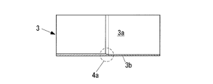
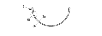
- FIG. 1A to 1C are explanatory views of the FRP component 3 manufactured by the present invention.
- the FRP component 3 manufactured by the present invention is an arc-shaped FRP component 3 having a radius of 1 m or more.
- FIG. 1A is a typical perspective view of the FRP component 3
- FIG. 1B is a side view of the FRP component 3 having a shape changing portion 4a in the middle in the axial direction
- FIG. 1C is a shape at an end portion in the circumferential direction. It is an end view of the FRP component 3 which has a change part 4b.
- Arc-shaped FRP part 3 with a radius of 1 m or more means a large FRP part such as the fuselage of an aircraft.
- the radius is, for example, 2 m, but may be 1 to 10 m.
- the axial length (axial length) is, for example, 8 m, but may be 10 cm to 20 m.
- the "arc shape" is, for example, an arc having a constant radius, but it is not strictly constant and may change partially or continuously.
- the circumferential angle (arc angle) of the arc is preferably 180 degrees or less, but may exceed 180 degrees as long as it does not interfere with the press frame 24 described later.
- the thickness of the FRP component 3 in the radial direction is preferably constant, but may be partially or continuously changed.
- the window frame of the fuselage of the aircraft and the door portion may be included.
- the shapes of the shape changing portions 4a and 4b are changed when the inner surface jig plate 10 and the outer surface jig plate 12, which will be described later, move in the radial direction orthogonal to the arc of the FRP component 3, the inner surface jig plate 10 and the outer surface jig. Set so that it does not interfere with the plate 12.
- the FRP molding system 100 of the present invention uses the inner surface jig plate 10 and the outer surface jig plate 12.
- FIG. 2A to 2C are explanatory views of the inner surface jig plate 10 and the outer surface jig plate 12.
- FIG. 2A is a typical perspective view of the inner surface jig plate 10 and the outer surface jig plate 12.
- FIG. 2B is a side view of the inner surface jig plate 10 and the outer surface jig plate 12 having the shape change portion 11a corresponding to the shape change portion 4a in the middle in the axial direction of the FRP component 3.
- FIG. 2C is an end view of the inner surface jig plate 10 and the outer surface jig plate 12 having the shape change portion 11b corresponding to the shape change portion 4b of the end portion in the circumferential direction of the FRP component 3.
- the inner surface jig plate 10 and the outer surface jig plate 12 are arc-shaped members, respectively.
- the inner surface jig plate 10 and the outer surface jig plate 12 are made of metal or a highly heat-resistant resin (for example, polyimide), and have a property of not being plastically deformed during molding of the FRP component 3.
- the inner surface jig plate 10 and the outer surface jig plate 12 may be elastically deformed at the time of molding the FRP component 3.
- the inner surface jig plate 10 has an outer surface 10b that fits with the inner surface shape 3a of the FRP component 3.
- the outer surface jig plate 12 has an inner surface 12a that fits with the outer surface shape 3b of the FRP component 3.
- “fitting” means a relationship in which male and female shapes are formed and no gap is formed between them when they are in close contact with each other.
- the inner surface jig plate 10 and the outer surface jig plate 12 have a surface shape corresponding to a change in the plate thickness or a change in the curvature of the FRP component 3 between them.
- the inner surface jig plate 10 has a shape changing portion 11a corresponding to a shape changing portion 4a in the middle in the axial direction of the FRP component 3.
- the inner surface jig plate 10 has a shape changing portion 11b corresponding to the shape changing portion 4b of the circumferential end portion of the FRP component 3.
- the FRP molding system 100 of the present invention is an apparatus for molding a plate-shaped FRP material 2 in which a plurality of prepregs 1 are laminated to manufacture an arc-shaped FRP component 3 having a radius of 1 m or more.
- Prepreg 1 is an intermediate material obtained by impregnating a base material made of reinforcing fibers (for example, glass fibers or carbon fibers) with a resin.
- the resin is preferably a thermoplastic resin, but may be a thermosetting resin. The resin before molding is solidified in the thermoplastic resin and softened (uncured) in the thermosetting resin.
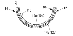
- the FRP molding system 100 of the present invention uses an integrated member (hereinafter, "integrated jig plate 14") in which the FRP material 2 is sandwiched between the inner surface jig plate 10 and the outer surface jig plate 12.
- integrated jig plate 14 an integrated member in which the FRP material 2 is sandwiched between the inner surface jig plate 10 and the outer surface jig plate 12.
- FIGS. 2A to 2C are explanatory views of the integrated jig plate 14.
- the FRP material 2 is sandwiched between the inner surface jig plate 10 and the outer surface jig plate 12 at the positions of the FRP parts 3 in FIGS. 2A to 2C.
- FIG. 3A is a typical perspective view of the integrated jig plate 14 in which the FRP material 2 is sandwiched between the inner surface jig plate 10 and the outer surface jig plate 12 of FIG. 2A.
- FIG. 3B is a side view of the integrated jig plate 14 in which the FRP material 2 is sandwiched between the inner surface jig plate 10 and the outer surface jig plate 12 of FIG. 2B.
- FIG. 3C is an end view of the integrated jig plate 14 in which the FRP material 2 is sandwiched between the inner surface jig plate 10 and the outer surface jig plate 12 of FIG. 2C.
- FIG. 3A is a typical perspective view of the integrated jig plate 14 in which the FRP material 2 is sandwiched between the inner surface jig plate 10 and the outer surface jig plate 12 of FIG. 2A.
- FIG. 3B is a side view of the integrated jig plate 14 in which the FRP material 2
- the FRP material 2 has a shape change portion 2a corresponding to the shape change portion 4a of the FRP component 3.
- the FRP component 3 having no change in plate thickness or curvature is manufactured, it is not necessary to use the inner surface jig plate 10 and the outer surface jig plate 12.
- the inner surface jig plate 10 and the outer surface jig plate 12 are fixed with a fixing jig (not shown) so as not to separate from each other with the FRP material 2 sandwiched between them.
- This fixing jig does not interfere with the lower mold 18 when the lower mold 18 is pressed against the upper mold 16 described later, and the outer jig plate is opposed to the inner jig plate 10 in the radial direction orthogonal to the arc of the FRP component 3. 12 is set to be movable.
- FRP material 2 is a material in which a plurality of prepregs 1 are laminated and becomes an FRP part 3 after molding.
- the FRP material 2 is preferably a plate-shaped member.
- the FRP material 2 is a contoured laminated body that matches the thickness distribution of the FRP component 3.
- the FRP material 2 may be laminated in a plane shape or may be laminated in accordance with an arcuate molding shape.
- the thickness of the FRP material 2 corresponds to the thickness of the FRP component 3 in the radial direction, and is set in consideration of the change in thickness during molding. Further, it is preferable to change the number of laminated prepregs 1 according to the change in the thickness of the FRP component 3.
- the width of the FRP material 2 corresponds to the circumferential length of the arc of the FRP component 3.
- the length of the FRP material 2 corresponds to the axial length of the FRP component 3.
- the inner surface 14a and the outer surface 14b of the integrated jig plate 14 have arc surfaces that are concentric with each other and have a constant radius.
- the inner surface 14a of the integrated jig plate 14 is the inner surface 10a of the inner surface jig plate 10
- the outer surface 14b of the integrated jig plate 14 is the outer surface 12b of the outer surface jig plate 12. Therefore, the inner surface 10a of the inner surface jig plate 10 and the outer surface 12b of the outer surface jig plate 12 have an arcuate surface having a substantially concentric radius when the FRP material 2 is sandwiched between them and integrated.
- substantially means that the thickness of the FRP material 2 is not strictly concentric before molding, but becomes concentric after molding.
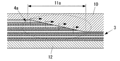
- FIG. 4A is a diagram showing a shape changing portion 2a of the FRP material 2
- FIG. 4B is a diagram showing a shape changing portion 4a of the FRP component 3.
- the shape changing portion 2a of the FRP material 2 is configured by changing, for example, the number of laminated prepregs 1.
- the fiber directions of the prepreg 1 are preferably different from each other, but some or all of them may be the same.
- the thickness is set to be thicker than the thickness of the FRP component 3 in consideration of the change in thickness during molding.
- the shape changing portion 2a of the FRP material 2 becomes stepped depending on the thickness of the prepreg 1.
- the resin and fibers flow in the in-plane direction during molding due to the change in thickness (decrease in thickness) of the FRP material 2. Therefore, it is desirable, but not limited to, the shape changing portion 2a of the FRP material 2 to be set so as to be located within the range of the shape changing portion 11a of the inner surface jig plate 10.
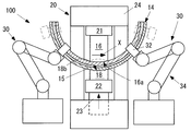
- FIG. 5A is a front view of the FRP molding system 100 according to the present invention, and FIG. 5B is a side view thereof. Note that FIG. 5B shows the process of molding.
- the FRP molding system 100 further includes an upper die 16 and a lower die 18.
- the upper die 16 and the lower die 18 sandwich a part (pressed portion 15) of the integrated jig plate 14 in the vertical direction.
- the upper die 16 has an inner arc surface 16a that is in close contact with the inner surface 14a of the integrated jig plate 14.
- the lower mold 18 has an outer arc surface 18b that is in close contact with the outer surface 14b of the integrated jig plate 14.
- the upper die 16 and the lower die 18 simultaneously compress the entire axial length (axial length) of the integrated jig plate 14.
- the FRP molding system 100 further includes a partial press device 20 and a transfer device 30.
- the partial pressing device 20 intermittently compresses a part (pressed portion 15) of the integrated jig plate 14 in the radial direction (vertical direction in the figure) orthogonal to the arc of the FRP component 3 to partially compress the FRP component 3. Mold. "Intermittent compression" means that the partial press device 20 and the transfer device 30 repeatedly compress and transfer the integrated jig plate 14.
- the partial pressing device 20 compresses a part of the integrated jig plate 14 with the upper die 16 and the lower die 18.
- the partial press device 20 includes an upper bolster 21 that fixes the upper mold 16 on the lower surface, a slide 22 that fixes the lower mold 18 on the upper surface, a hydraulic ram 23 that reciprocates the slide 22 up and down, and an upper portion. It has a bolster 21 and a press frame 24 to which the hydraulic ram 23 is fixed.
- the partial press device 20 pushes up the lower die 18 with respect to the upper die 16 to compress the press portion 15 of the integrated jig plate 14.
- the partial pressing device 20 compresses the pressing portion 15 in the radial direction of the inner arc surface 16a or the outer arc surface 18b.
- the upper structure of the press frame 24 is set so as not to interfere with the integrated jig plate 14 when the compressed portion of the integrated jig plate 14 is intermittently moved.
- the vertical relationship between the bolster, the slide 22, and the liquid ram 23 may be reversed. That is, the slide 22 and the liquid ram 23 may be at the top and the bolster may be at the bottom.
- the transfer device 30 intermittently moves the compressed portion (press portion 15) of the integrated jig plate 14 by the partial press device 20.
- the transport device 30 has a gripping device 32 and a moving device 34.
- the gripping device 32 partially grips the integrated jig plate 14.
- the moving device 34 moves the gripping device 32 in the moving direction X of the integrated jig plate 14.
- the moving direction X of the integrated jig plate 14 is the circumferential direction along the arc of the FRP component 3.
- the moving device 34 is, for example, an articulated robot, and the gripping device 32 is a robot hand.
- the pair of transfer devices 30 are provided on the upstream side and the downstream side of the partial press device 20, but only one of the upstream side or the downstream side may be provided.
- the gripping device 32 grips the uncompressed portion of the integrated jig plate 14. In this case, for example, the gripped portion may be moved during compression by the partial press device 20.
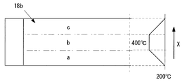
- the FRP molding system 100 further includes a heating device 40 for heating the upper die 16 or the lower die 18.
- the heating device 40 has a predetermined temperature distribution with respect to the moving direction X of the integrated jig plate 14.
- FIG. 6A is an explanatory diagram of the temperature distribution of the upper mold 16, and FIG. 6B is an explanatory diagram of the temperature distribution of the lower mold 18.
- the prepreg 1 contains a thermoplastic resin.
- FIG. 6A shows the inner arc surface 16a of the upper die 16, and
- FIG. 6B shows the outer arc surface 18b of the lower die 18.
- reference numerals a, b, and c in the figure indicate a preheating zone, a main molding zone, and a cooling zone, respectively.
- the temperature distribution of the upper die 16 and the lower die 18 is equal to or higher than the melting temperature at which the thermoplastic resin flows in the central portion (main molding zone b) of the moving direction X of the integrated jig plate 14 (for example, 400 ° C. or higher). Is. Further, the temperature is lower than the solidification temperature (for example, 200 ° C. to less than 400 ° C.) at which the thermoplastic resin solidifies on the upstream side (preheating zone a) and the downstream side (cooling zone c) of the central portion of the moving direction X.
- the reason why the preheating zone a and the cooling zone c are set below the solidification temperature is that when the whole is set above the melting temperature, for example, in the case of CFRP having high thermal conductivity, the uncompressed portion is softened by heat transfer. For example, it becomes difficult to uniformly mold the entire FRP component 3 because the extremely small bubbles once pressure-compressed swell in the out-of-plane direction.
- the above temperature distribution is a temperature distribution at the time of molding the FRP component 3, and it is preferable that the entire surface of the inner arc surface 16a or the outer arc surface 18b is 200 ° C. or less during transportation.
- the temperature distribution is equal to or higher than the curing temperature at which the thermosetting resin is cured in the central portion (main molding zone b) of the moving direction X of the integrated jig plate 14.
- the curing temperature of the thermosetting resin is, for example, about 180 ° C. Further, the temperature is preheated to less than the curing temperature on the upstream side (preheating zone a) of the central portion in the moving direction X. Further, in the case of a thermosetting resin, the cooling zone c is unnecessary and can be omitted.
- FIG. 7 is an overall flow chart of the FRP molding method according to the present invention.
- the FRP molding method according to the present invention is a method of molding a plate-shaped FRP material 2 in which a plurality of prepregs 1 are laminated to manufacture an arc-shaped FRP component 3 having a radius of 1 m or more.
- the FRP molding method has each step (step) of S1 to S5.
- an arc-shaped inner surface jig plate 10 having an outer surface 10b that fits with the inner surface shape 3a of the FRP component 3 and an arc-shaped inner surface 12a having an inner surface 12a that fits with the outer surface shape 3b of the FRP component 3
- the outer surface jig plate 12 and the like are prepared.
- the integrated jig plate 14 is formed by sandwiching the FRP material 2 between the inner surface jig plate 10 and the outer surface jig plate 12.
- a mold release agent for example, a fluorine-based mold release agent
- the partial pressing step S3 a part of the integrated jig plate 14 is intermittently compressed in the radial direction orthogonal to the arc of the FRP component 3 to partially form the FRP component 3.
- the compressed portion (press portion 15) of the integrated jig plate 14 according to the partial press step S3 is intermittently moved.
- the partial pressing step S3 and the conveying step S4 are repeated to compress the entire integral jig plate 14 to form the entire FRP component 3.
- the FRP component 3 formed by separating the inner surface jig plate 10 and the outer surface jig plate 12 from the integrated jig plate 14 is taken out.
- a part of the integrated jig plate 14 in which the FRP material 2 is sandwiched between the inner surface jig plate 10 and the outer surface jig plate 12 is intermittently compressed. Then, the FRP part 3 is partially molded. Further, in the transfer step S4, the compressed portion (pressed portion 15) of the integrated jig plate 14 is intermittently moved. Therefore, by repeating the partial pressing step S3 and the conveying step S4, an arc-shaped FRP part 3 (for example, a large FRP part having a radius of 1 m or more) can be molded and manufactured with a small die.
- a part of the integrated jig plate 14 is compressed (pressurized) in the radial direction orthogonal to the arc of the FRP component 3, so that the entire FRP component 3 can be formed without using a complicated die. Can be molded uniformly.
- the present invention is not limited to the above-described embodiment, and it goes without saying that various modifications can be made without departing from the gist of the present invention.
- the FRP component 3 has an arc shape, but the present invention can be similarly applied to a flat FRP component.
Abstract
Description
そのため、近年、アルミニウム合金に代わる構造部材として、航空機、小型船舶、自動車等に、用いられている。以下、繊維強化複合材を単に、「FRP」と呼ぶ。 Fiber reinforced composites, such as CFRP (carbon fiber reinforced plastic), have excellent mechanical properties, high specific strength, light weight, and strong characteristics, while having a lower density than metal materials such as iron and aluminum.
Therefore, in recent years, it has been used in aircraft, small ships, automobiles, etc. as a structural member in place of aluminum alloy. Hereinafter, the fiber reinforced composite material is simply referred to as "FRP".
そこで、例えば、特許文献1の手段を用いて大型FRP成形品を製造することが考えられる。 For example, aircraft structures (fuselage, hatches, wings, etc.) have traditionally riveted aluminum alloys together. However, joining using rivets has poor workability, and when applied to a fiber-reinforced composite material, the internal fibers are cut, so that the tensile strength is extremely lowered.
Therefore, for example, it is conceivable to manufacture a large-sized FRP molded product by using the means of Patent Document 1.
(1)大型FRP部品を加圧できる大型の金型と大型のプレス機が必要になる。
(2)円弧状のFRP部品を成形する場合、成形品の均質化のためにFRP部品の円弧に直交する半径方向に加圧する必要がある。
しかし、この場合、FRP部品の円弧に対し半径方向に加圧する金型は、構造が複雑となる。 When molding a large FRP part (an arcuate FRP part having a radius of 1 m or more) such as an aircraft fuselage, Patent Document 1 described above has the following problems.
(1) A large die and a large press that can pressurize large FRP parts are required.
(2) When molding an arc-shaped FRP part, it is necessary to pressurize in the radial direction orthogonal to the arc of the FRP part in order to homogenize the molded product.
However, in this case, the structure of the mold that pressurizes the arc of the FRP component in the radial direction becomes complicated.
前記FRP部品の内面形状と嵌合する外面を有する円弧状の内面治具プレートと、
前記FRP部品の外面形状と嵌合する内面を有する円弧状の外面治具プレートと、
前記内面治具プレートと前記外面治具プレートの間に前記FRP素材が挟まれた一体治具プレートの一部を前記FRP部品の円弧に直交する半径方向に間欠的に圧縮して前記FRP部品を部分的に成形する部分プレス装置と、
前記部分プレス装置による前記一体治具プレートの圧縮部分を間欠的に移動する搬送装置と、を備えたFRP成形システムが提供される。 According to the present invention, it is an FRP molding system for manufacturing an arc-shaped FRP component by molding a plate-shaped FRP material in which a plurality of prepregs are laminated.
An arcuate inner surface jig plate having an outer surface that fits with the inner surface shape of the FRP component, and
An arcuate outer surface jig plate having an inner surface that fits with the outer surface shape of the FRP component,
A part of the integrated jig plate in which the FRP material is sandwiched between the inner surface jig plate and the outer surface jig plate is intermittently compressed in the radial direction orthogonal to the arc of the FRP component to form the FRP component. Partial press equipment for partial molding and
An FRP molding system including a transfer device for intermittently moving a compressed portion of the integrated jig plate by the partial press device is provided.
前記FRP部品の内面形状と嵌合する外面を有する円弧状の内面治具プレートと、前記FRP部品の外面形状と嵌合する内面を有する円弧状の外面治具プレートと、を準備する治具準備工程と、
前記内面治具プレートと前記外面治具プレートの間に前記FRP素材を挟んで一体治具プレートを形成する治具一体化工程と、
前記一体治具プレートの一部を前記FRP部品の円弧に直交する半径方向に間欠的に圧縮して前記FRP部品を部分的に成形する部分プレス工程と、
前記部分プレス工程による前記一体治具プレートの圧縮部分を間欠的に移動する搬送工程と、を有し、
前記部分プレス工程と前記搬送工程と、を繰り返す、FRP成形方法が提供される。 Further, according to the present invention, it is an FRP molding method for manufacturing an arc-shaped FRP component by molding a plate-shaped FRP material in which a plurality of prepregs are laminated.
Jig preparation for preparing an arc-shaped inner surface jig plate having an outer surface that fits the inner surface shape of the FRP component and an arc-shaped outer surface jig plate having an inner surface that fits the outer surface shape of the FRP component. Process and
A jig integration step of forming an integrated jig plate by sandwiching the FRP material between the inner surface jig plate and the outer surface jig plate.
A partial pressing step of intermittently compressing a part of the integrated jig plate in the radial direction orthogonal to the arc of the FRP part to partially form the FRP part.
It has a transfer step of intermittently moving the compressed portion of the integrated jig plate by the partial press step.
An FRP molding method is provided in which the partial pressing step and the conveying step are repeated.
本発明により製造するFRP部品3は、半径が1m以上の円弧状のFRP部品3である。例として、図1Aは、FRP部品3の代表的な斜視図、図1Bは、軸方向の中間に形状変化部4aを有するFRP部品3の側面図、図1Cは、周方向の端部に形状変化部4bを有するFRP部品3の端面図である。 1A to 1C are explanatory views of the
The
なお「嵌合する」とは、互いに雄雌の形状であり、密着した際にその間に隙間が生じない関係を意味する。 As shown in FIG. 2A, the inner
In addition, "fitting" means a relationship in which male and female shapes are formed and no gap is formed between them when they are in close contact with each other.
例として、図2Bにおいて、内面治具プレート10は、FRP部品3の軸方向中間の形状変化部4aに対応する形状変化部11aを有する。また、図2Cにおいて、内面治具プレート10は、FRP部品3の周方向端部の形状変化部4bに対応する形状変化部11bを有する。 Further, the inner
As an example, in FIG. 2B, the inner
成形前の樹脂は、熱可塑性樹脂では固化しており、熱硬化性樹脂では軟化(未硬化)している。 "Prepreg 1" is an intermediate material obtained by impregnating a base material made of reinforcing fibers (for example, glass fibers or carbon fibers) with a resin. In the present invention, the resin is preferably a thermoplastic resin, but may be a thermosetting resin.
The resin before molding is solidified in the thermoplastic resin and softened (uncured) in the thermosetting resin.
なお、図3Bにおいて、FRP素材2は、FRP部品3の形状変化部4aに対応する形状変化部2aを有する。図3Cの場合も同様である。
また、板厚変化も曲率変化も無いFRP部品3を作るときは、内面治具プレート10及び外面治具プレート12を使用しなくてもよい。 FIG. 3A is a typical perspective view of the
In addition, in FIG. 3B, the
Further, when the
この固定治具は、後述する上型16に対し下型18を押し付ける際に、これらと干渉せず、かつFRP部品3の円弧に直交する半径方向に内面治具プレート10に対し外面治具プレート12が移動可能に設定されている。 The inner
This fixing jig does not interfere with the
FRP素材2の幅は、FRP部品3の円弧の周方向長さに相当する。FRP素材2の長さは、FRP部品3の軸方向長さに相当する。 The thickness of the
The width of the
ここで、「実質的に」とは、FRP素材2の厚さにより成形前は厳密には同心ではないが、成形後に同心となることを意味する。 In this example, the
Here, "substantially" means that the thickness of the
この際、樹脂が熱可塑性樹脂である場合には、加熱後に冷却し、樹脂が、熱硬化性樹脂である場合には加熱して硬化させる。
FRP素材2の成形時に、樹脂および繊維の一部が流動して移動し、図4Bに示すように、内面治具プレート10の形状変化部11aに密着したFRP部品3の形状変化部4aが成形される。 In FIG. 4B, when the
At this time, if the resin is a thermoplastic resin, it is cooled after heating, and if the resin is a thermosetting resin, it is heated and cured.
During molding of the
上型16は、一体治具プレート14の内面14aに密着する内面円弧面16aを有する。下型18は、一体治具プレート14の外面14bに密着する外面円弧面18bを有する。 The
The
「間欠的に圧縮」とは、部分プレス装置20と搬送装置30により、一体治具プレート14の圧縮と搬送を繰り返すことを意味する。 The partial
"Intermittent compression" means that the
この例では、部分プレス装置20は、下面に上型16を固定する上部ボルスター21と、上面に下型18を固定するスライド22と、スライド22を上下に往復動させる液圧ラム23と、上部ボルスター21と液圧ラム23が固定されたプレスフレーム24とを有する。 The partial
In this example, the
プレスフレーム24は、一体治具プレート14の圧縮部分を間欠的に移動する際に、一体治具プレート14と干渉しないように、上部構造が設定されている。
なお、一体治具プレート14とプレス上部構造が干渉しない限りで、ボルスタとスライド22、液状ラム23の上下関係が逆となっても良い。すなわちスライド22と液状ラム23が上部で、ボルスタが下部にあっても良い。 In this example, the
The upper structure of the
As long as the
搬送装置30は、把持装置32と移動装置34とを有する。
把持装置32は、一体治具プレート14を部分的に把持する。移動装置34は、把持装置32を一体治具プレート14の移動方向Xに移動する。 The
The
The
また、把持装置32は、一体治具プレート14の非圧縮部分を把持する。この場合、例えば部分プレス装置20による圧縮中に把持部分を移動してもよい。 In this example, the pair of
Further, the gripping
加熱装置40は、一体治具プレート14の移動方向Xに対し、所定の温度分布を有する。 In FIGS. 5A and 5B, the
The
この例は、プリプレグ1が熱可塑性樹脂を含む場合である。図6Aは、上型16の内面円弧面16aを示し、図6Bは、下型18の外面円弧面18bを示している。また、図中の符号a,b,cは、予備加熱ゾーン、本成形ゾーン、冷却ゾーンをそれぞれ示している。 FIG. 6A is an explanatory diagram of the temperature distribution of the
This example is the case where the prepreg 1 contains a thermoplastic resin. FIG. 6A shows the
また、上記の温度分布は、FRP部品3の成形時の温度分布であり、搬送時には、内面円弧面16a又は外面円弧面18bの全面が200℃以下であるのがよい。 The reason why the preheating zone a and the cooling zone c are set below the solidification temperature is that when the whole is set above the melting temperature, for example, in the case of CFRP having high thermal conductivity, the uncompressed portion is softened by heat transfer. For example, it becomes difficult to uniformly mold the
Further, the above temperature distribution is a temperature distribution at the time of molding the
本発明によるFRP成形方法は、複数のプリプレグ1が積層された板状のFRP素材2を成形して半径が1m以上の円弧状のFRP部品3を製造する方法である。 FIG. 7 is an overall flow chart of the FRP molding method according to the present invention.
The FRP molding method according to the present invention is a method of molding a plate-shaped
搬送工程S4では、部分プレス工程S3による一体治具プレート14の圧縮部分(プレス部分15)を間欠的に移動する。
部分プレス工程S3と搬送工程S4とを繰り返して、一体治具プレート14の全部を圧縮してFRP部品3の全体を成形する。 In the partial pressing step S3, a part of the
In the transfer step S4, the compressed portion (press portion 15) of the
The partial pressing step S3 and the conveying step S4 are repeated to compress the entire
例えば、上述した例では、FRP部品3は円弧状であるが、本発明は、フラット形状のFRP部品にも同様に適用することができる。 It should be noted that the present invention is not limited to the above-described embodiment, and it goes without saying that various modifications can be made without departing from the gist of the present invention.
For example, in the above example, the
a Preheating zone, b Main molding zone, c Cooling zone, X movement direction, 1 prepreg, 2 FRP material, 2a, 2b shape change part, 3 FRP parts, 3a inner surface shape, 3b outer surface shape, 4a, 4b
Claims (10)
- 複数のプリプレグが積層された板状のFRP素材を成形して円弧状のFRP部品を製造するFRP成形システムであって、
前記FRP部品の内面形状と嵌合する外面を有する円弧状の内面治具プレートと、
前記FRP部品の外面形状と嵌合する内面を有する円弧状の外面治具プレートと、
前記内面治具プレートと前記外面治具プレートの間に前記FRP素材が挟まれた一体治具プレートの一部を前記FRP部品の円弧に直交する半径方向に間欠的に圧縮して前記FRP部品を部分的に成形する部分プレス装置と、
前記部分プレス装置による前記一体治具プレートの圧縮部分を間欠的に移動する搬送装置と、を備えたFRP成形システム。 It is an FRP molding system that manufactures arc-shaped FRP parts by molding a plate-shaped FRP material in which a plurality of prepregs are laminated.
An arcuate inner surface jig plate having an outer surface that fits with the inner surface shape of the FRP component, and
An arcuate outer surface jig plate having an inner surface that fits with the outer surface shape of the FRP component,
A part of the integrated jig plate in which the FRP material is sandwiched between the inner surface jig plate and the outer surface jig plate is intermittently compressed in the radial direction orthogonal to the arc of the FRP component to form the FRP component. Partial press equipment for partial molding and
An FRP molding system including a transfer device that intermittently moves a compressed portion of the integrated jig plate by the partial press device. - 前記内面治具プレート及び前記外面治具プレートは、その間に前記FRP部品の板厚変化又は曲率変化に対応した面形状を有し、
前記一体治具プレートの内面と外面は、同心かつそれぞれ半径一定の円弧面を有する、請求項1に記載のFRP成形システム。 The inner surface jig plate and the outer surface jig plate have a surface shape corresponding to a change in plate thickness or a change in curvature of the FRP component between them.
The FRP molding system according to claim 1, wherein the inner surface and the outer surface of the integrated jig plate have arcuate surfaces that are concentric and each have a constant radius. - さらに、前記一体治具プレートの前記一部を間に挟さむ上型及び下型を備え、
前記上型は、前記一体治具プレートの内面に密着する内面円弧面を有し、
前記下型は、前記一体治具プレートの外面に密着する外面円弧面を有し、
前記部分プレス装置は、前記上型と前記下型で前記一部を圧縮する、請求項2に記載のFRP成形システム。 Further, an upper die and a lower die for sandwiching the part of the integrated jig plate are provided.
The upper mold has an inner arc surface that is in close contact with the inner surface of the integrated jig plate.
The lower mold has an outer arc surface that is in close contact with the outer surface of the integrated jig plate.
The FRP molding system according to claim 2, wherein the partial pressing device compresses a part of the upper mold and the lower mold. - 前記上型又は前記下型を加熱する加熱装置を備え、
前記加熱装置は、前記一体治具プレートの移動方向に対し、所定の温度分布を有する、請求項3に記載のFRP成形システム。 A heating device for heating the upper mold or the lower mold is provided.
The FRP molding system according to claim 3, wherein the heating device has a predetermined temperature distribution with respect to the moving direction of the integrated jig plate. - 前記プリプレグは、熱可塑性樹脂を含み、
前記温度分布は、前記移動方向の中央部において前記熱可塑性樹脂が流動する溶融温度以上であり、前記中央部の上流側及び下流側において前記熱可塑性樹脂が固化する固化温度以下である、請求項4に記載のFRP成形システム。 The prepreg contains a thermoplastic resin and contains
The temperature distribution is equal to or higher than the melting temperature at which the thermoplastic resin flows in the central portion in the moving direction, and is equal to or lower than the solidification temperature at which the thermoplastic resin solidifies on the upstream side and the downstream side of the central portion. The FRP molding system according to 4. - 前記プリプレグは、熱硬化性樹脂を含み、
前記温度分布は、前記移動方向の中央部において前記熱硬化性樹脂が硬化する硬化温度以上である、請求項4に記載のFRP成形システム。 The prepreg contains a thermosetting resin and contains
The FRP molding system according to claim 4, wherein the temperature distribution is equal to or higher than the curing temperature at which the thermosetting resin is cured in the central portion in the moving direction. - 前記搬送装置は、前記一体治具プレートを部分的に把持する把持装置と、
前記把持装置を前記一体治具プレートの移動方向に移動する移動装置と、を有する、請求項1に記載のFRP成形システム。 The transport device includes a gripping device that partially grips the integrated jig plate.
The FRP molding system according to claim 1, further comprising a moving device that moves the gripping device in the moving direction of the integrated jig plate. - 複数のプリプレグが積層された板状のFRP素材を成形して円弧状のFRP部品を製造するFRP成形方法であって、
前記FRP部品の内面形状と嵌合する外面を有する円弧状の内面治具プレートと、前記FRP部品の外面形状と嵌合する内面を有する円弧状の外面治具プレートと、を準備する治具準備工程と、
前記内面治具プレートと前記外面治具プレートの間に前記FRP素材を挟んで一体治具プレートを形成する治具一体化工程と、
前記一体治具プレートの一部を前記FRP部品の円弧に直交する半径方向に間欠的に圧縮して前記FRP部品を部分的に成形する部分プレス工程と、
前記部分プレス工程による前記一体治具プレートの圧縮部分を間欠的に移動する搬送工程と、を有し、
前記部分プレス工程と前記搬送工程と、を繰り返す、FRP成形方法。 It is an FRP molding method that manufactures arc-shaped FRP parts by molding a plate-shaped FRP material in which a plurality of prepregs are laminated.
Jig preparation for preparing an arc-shaped inner surface jig plate having an outer surface that fits the inner surface shape of the FRP component and an arc-shaped outer surface jig plate having an inner surface that fits the outer surface shape of the FRP component. Process and
A jig integration step of forming an integrated jig plate by sandwiching the FRP material between the inner surface jig plate and the outer surface jig plate.
A partial pressing step of intermittently compressing a part of the integrated jig plate in the radial direction orthogonal to the arc of the FRP part to partially form the FRP part.
It has a transfer step of intermittently moving the compressed portion of the integrated jig plate by the partial press step.
An FRP molding method in which the partial pressing step and the conveying step are repeated. - 前記一体治具プレートから前記内面治具プレートと前記外面治具プレートを分離して成形された前記FRP部品を取り出す離型工程を有する、請求項8に記載のFRP成形方法。 The FRP molding method according to claim 8, further comprising a mold release step of taking out the FRP component formed by separating the inner surface jig plate and the outer surface jig plate from the integrated jig plate.
- 前記治具一体化工程において、前記内面治具プレートの前記外面と前記外面治具プレートの前記内面に離型剤を塗布する、請求項8に記載のFRP成形方法。 The FRP molding method according to claim 8, wherein in the jig integration step, a mold release agent is applied to the outer surface of the inner surface jig plate and the inner surface of the outer surface jig plate.
Priority Applications (8)
| Application Number | Priority Date | Filing Date | Title |
|---|---|---|---|
| RU2021114073A RU2764456C1 (en) | 2019-03-08 | 2019-03-08 | Frp forming system and method |
| JP2019529290A JP6766268B1 (en) | 2019-03-08 | 2019-03-08 | FRP molding system and method |
| PCT/JP2019/009486 WO2020183545A1 (en) | 2019-03-08 | 2019-03-08 | Frp molding system and method |
| CN201980073343.1A CN112996653B (en) | 2019-03-08 | 2019-03-08 | FRP forming system and method |
| ES19919108T ES2954766T3 (en) | 2019-03-08 | 2019-03-08 | Molding system and method of a fiber reinforced composite material |
| EP19919108.1A EP3936317B1 (en) | 2019-03-08 | 2019-03-08 | Fibre reinforced composite material molding system and method |
| US17/295,163 US11826976B2 (en) | 2019-03-08 | 2019-03-08 | FRP molding system and method |
| CA3119802A CA3119802C (en) | 2019-03-08 | 2019-03-08 | Frp molding system and method |
Applications Claiming Priority (1)
| Application Number | Priority Date | Filing Date | Title |
|---|---|---|---|
| PCT/JP2019/009486 WO2020183545A1 (en) | 2019-03-08 | 2019-03-08 | Frp molding system and method |
Publications (1)
| Publication Number | Publication Date |
|---|---|
| WO2020183545A1 true WO2020183545A1 (en) | 2020-09-17 |
Family
ID=72426192
Family Applications (1)
| Application Number | Title | Priority Date | Filing Date |
|---|---|---|---|
| PCT/JP2019/009486 WO2020183545A1 (en) | 2019-03-08 | 2019-03-08 | Frp molding system and method |
Country Status (8)
| Country | Link |
|---|---|
| US (1) | US11826976B2 (en) |
| EP (1) | EP3936317B1 (en) |
| JP (1) | JP6766268B1 (en) |
| CN (1) | CN112996653B (en) |
| CA (1) | CA3119802C (en) |
| ES (1) | ES2954766T3 (en) |
| RU (1) | RU2764456C1 (en) |
| WO (1) | WO2020183545A1 (en) |
Families Citing this family (2)
| Publication number | Priority date | Publication date | Assignee | Title |
|---|---|---|---|---|
| JP2023012200A (en) | 2021-07-13 | 2023-01-25 | 川崎重工業株式会社 | Molding apparatus and molding method |
| US20230391025A1 (en) * | 2022-06-03 | 2023-12-07 | Rohr, Inc. | Smart materials to form nacelle core structure |
Citations (6)
| Publication number | Priority date | Publication date | Assignee | Title |
|---|---|---|---|---|
| JPS6219440A (en) * | 1985-07-19 | 1987-01-28 | Hitachi Zosen Corp | Molding of fuselage of airplane |
| JP2002538991A (en) * | 1999-03-18 | 2002-11-19 | エイチ. スチュワート,デイビッド | Method and machine for manufacturing a molded structure using regionalized pressure molding |
| JP2008222221A (en) * | 2004-04-06 | 2008-09-25 | Boeing Co:The | Composite barrel section for aircraft fuselage and other structure, and method and system for manufacturing the barrel section |
| JP2015009396A (en) | 2013-06-27 | 2015-01-19 | 天龍コンポジット株式会社 | Method for manufacturing frp molded product, and frp molded product |
| JP2017061135A (en) * | 2015-07-09 | 2017-03-30 | ザ・ボーイング・カンパニーThe Boeing Company | Reducing wrinkling of contoured hat stiffeners formed from single composite charge |
| WO2018101422A1 (en) * | 2016-12-01 | 2018-06-07 | 川崎重工業株式会社 | Method for producing composite material structure |
Family Cites Families (29)
| Publication number | Priority date | Publication date | Assignee | Title |
|---|---|---|---|---|
| GB527906A (en) * | 1939-02-11 | 1940-10-18 | Ebonestos Ind Ltd | Improvements in and relating to the moulding of articles from synthetic resins |
| US3383266A (en) | 1963-01-25 | 1968-05-14 | Roy S. Helm | Method and apparatus for manufacturing fiber reinforced plastic sheets |
| US4904436A (en) | 1988-01-29 | 1990-02-27 | Phillips Petroleum Company | Consolidation of thermoplastic panels |
| JP3754313B2 (en) | 2001-03-30 | 2006-03-08 | 川崎重工業株式会社 | Reaction prevention method and reaction suppression method during sandwich structure production |
| JP2004322442A (en) | 2003-04-24 | 2004-11-18 | Toray Ind Inc | Method and apparatus for producing frp preform |
| NL1030066C2 (en) * | 2005-09-29 | 2007-03-30 | Gtm Consulting B V | Method for manufacturing a molded part from a composite material. |
| WO2007102573A1 (en) * | 2006-03-08 | 2007-09-13 | Toray Industries, Inc. | Process, and apparatus, for producing reinforcing fiber molding |
| FR2898539B1 (en) * | 2006-03-20 | 2008-05-23 | Eads Ccr Groupement D Interet | METHOD FOR PRODUCING RAIDIS PANELS IN COMPOSITE MATERIAL AND PANELS PRODUCED |
| JP5116282B2 (en) * | 2006-10-31 | 2013-01-09 | 株式会社ジャムコ | Continuous production method for structural members |
| WO2010089863A1 (en) * | 2009-02-04 | 2010-08-12 | サカイ・コンポジット株式会社 | Process for producing tubular structure made of fiber-reinforced resin and tubular structure made of fiber-reinforced resin |
| EP2338668A1 (en) * | 2009-12-22 | 2011-06-29 | Lm Glasfiber A/S | Method of producing a composite shell structure |
| CN102753321A (en) * | 2010-02-23 | 2012-10-24 | 东丽株式会社 | Preform and method for manufacturing the same |
| US10821653B2 (en) * | 2010-02-24 | 2020-11-03 | Alexander M. Rubin | Continuous molding of thermoplastic laminates |
| DE102010002988B4 (en) | 2010-03-17 | 2014-07-17 | Zf Friedrichshafen Ag | Method and device for the continuous production of profile components made of fiber composite material |
| JP5966617B2 (en) * | 2012-05-28 | 2016-08-10 | Jfeスチール株式会社 | Closed-section structure forming method and closed-section structure forming apparatus |
| JP6121740B2 (en) * | 2013-02-13 | 2017-04-26 | 株式会社Ihi | Fan blade manufacturing method and manufacturing apparatus |
| CN203613420U (en) | 2013-10-22 | 2014-05-28 | 泰州新源电工器材有限公司 | Press-molding mold for integral angle ring for electric reactor |
| CN103660311B (en) * | 2013-11-29 | 2015-11-04 | 北京卫星制造厂 | A kind of integral forming method of Varying-thickness complex configuration composite joint |
| DE102013226753A1 (en) * | 2013-12-19 | 2015-06-25 | Airbus Operations Gmbh | Apparatus and method for the continuous production of structural components made of fiber-reinforced composite materials and mold set |
| JP6436451B2 (en) * | 2014-05-27 | 2018-12-12 | 小島プレス工業株式会社 | WOODEN DESIGN PARTS AND ITS MANUFACTURING METHOD |
| JP6504993B2 (en) * | 2014-11-28 | 2019-04-24 | 三菱電機株式会社 | Method of manufacturing curved sandwich structure |
| CN205056811U (en) * | 2015-09-18 | 2016-03-02 | 上海东海压力容器制造有限公司 | A mould system for processing AP1000 steam generator is buckled plate for desicator |
| CN105365226B (en) * | 2015-12-16 | 2017-12-19 | 青岛林达科技开发有限公司 | Soft mode mold closing fibre reinforced composites product processing unit (plant) and processing method |
| JP5968566B1 (en) * | 2016-01-08 | 2016-08-10 | 株式会社The MOT Company | Manufacturing method of fiber reinforced composite material molded product and press mold used therefor |
| DE102016117103A1 (en) * | 2016-09-12 | 2018-03-15 | Airbus Operations Gmbh | Process for producing a fiber composite component |
| FR3062332B1 (en) * | 2017-01-30 | 2021-02-12 | Automotive Exteriors Europe | PRODUCTION PROCESS OF A PART, AND ASSOCIATED GRIPPING DEVICE |
| JP2018130927A (en) * | 2017-02-17 | 2018-08-23 | 本田技研工業株式会社 | Method for manufacturing composite member, and fixture used for the same |
| CN107283876B (en) * | 2017-08-01 | 2019-04-09 | 哈尔滨工业大学 | A method of preparing fibre reinforced fold sandwich cylindrical shell |
| CN109278242B (en) * | 2018-09-06 | 2019-11-12 | 华中科技大学 | A kind of method of integral forming thermoplastic composite structure on resin plastic |
-
2019
- 2019-03-08 RU RU2021114073A patent/RU2764456C1/en active
- 2019-03-08 JP JP2019529290A patent/JP6766268B1/en active Active
- 2019-03-08 CN CN201980073343.1A patent/CN112996653B/en active Active
- 2019-03-08 EP EP19919108.1A patent/EP3936317B1/en active Active
- 2019-03-08 ES ES19919108T patent/ES2954766T3/en active Active
- 2019-03-08 US US17/295,163 patent/US11826976B2/en active Active
- 2019-03-08 CA CA3119802A patent/CA3119802C/en active Active
- 2019-03-08 WO PCT/JP2019/009486 patent/WO2020183545A1/en active Application Filing
Patent Citations (6)
| Publication number | Priority date | Publication date | Assignee | Title |
|---|---|---|---|---|
| JPS6219440A (en) * | 1985-07-19 | 1987-01-28 | Hitachi Zosen Corp | Molding of fuselage of airplane |
| JP2002538991A (en) * | 1999-03-18 | 2002-11-19 | エイチ. スチュワート,デイビッド | Method and machine for manufacturing a molded structure using regionalized pressure molding |
| JP2008222221A (en) * | 2004-04-06 | 2008-09-25 | Boeing Co:The | Composite barrel section for aircraft fuselage and other structure, and method and system for manufacturing the barrel section |
| JP2015009396A (en) | 2013-06-27 | 2015-01-19 | 天龍コンポジット株式会社 | Method for manufacturing frp molded product, and frp molded product |
| JP2017061135A (en) * | 2015-07-09 | 2017-03-30 | ザ・ボーイング・カンパニーThe Boeing Company | Reducing wrinkling of contoured hat stiffeners formed from single composite charge |
| WO2018101422A1 (en) * | 2016-12-01 | 2018-06-07 | 川崎重工業株式会社 | Method for producing composite material structure |
Non-Patent Citations (1)
| Title |
|---|
| See also references of EP3936317A4 |
Also Published As
| Publication number | Publication date |
|---|---|
| EP3936317A1 (en) | 2022-01-12 |
| EP3936317B1 (en) | 2023-07-26 |
| JP6766268B1 (en) | 2020-10-07 |
| CN112996653B (en) | 2022-11-29 |
| CA3119802C (en) | 2023-06-27 |
| CA3119802A1 (en) | 2020-09-17 |
| EP3936317A4 (en) | 2022-10-19 |
| RU2764456C1 (en) | 2022-01-17 |
| CN112996653A (en) | 2021-06-18 |
| US11826976B2 (en) | 2023-11-28 |
| ES2954766T3 (en) | 2023-11-24 |
| US20220009178A1 (en) | 2022-01-13 |
| JPWO2020183545A1 (en) | 2021-03-18 |
Similar Documents
| Publication | Publication Date | Title |
|---|---|---|
| EP2914415B1 (en) | Method and apparatus for forming thermoplastic composite structures | |
| EP3115185B1 (en) | Reducing wrinkling of contoured hat stiffeners formed from a single composite charge | |
| US20200016796A1 (en) | Methods of making hybrid laminate and molded composite structures | |
| JP5252434B2 (en) | Excellent manufacturing process for thermoplastic composite laminates. | |
| US10821653B2 (en) | Continuous molding of thermoplastic laminates | |
| JP2010506768A (en) | Method for manufacturing curved thermoplastic composite parts | |
| JP6766268B1 (en) | FRP molding system and method | |
| JP2015536260A5 (en) | ||
| EP2889126B1 (en) | Method for producing composite material mold for composite material long member | |
| CN110104202B (en) | Composite aircraft manufacturing tool using articulated mandrels | |
| WO2022044324A1 (en) | Frp forming system and method | |
| JP2016047643A (en) | Composite filler forming apparatus | |
| CN112793279A (en) | Device and method for forming a composite laminate to obtain a Z-profile |
Legal Events
| Date | Code | Title | Description |
|---|---|---|---|
| ENP | Entry into the national phase |
Ref document number: 2019529290 Country of ref document: JP Kind code of ref document: A |
|
| 121 | Ep: the epo has been informed by wipo that ep was designated in this application |
Ref document number: 19919108 Country of ref document: EP Kind code of ref document: A1 |
|
| ENP | Entry into the national phase |
Ref document number: 3119802 Country of ref document: CA |
|
| NENP | Non-entry into the national phase |
Ref country code: DE |
|
| WWE | Wipo information: entry into national phase |
Ref document number: 2019919108 Country of ref document: EP |