WO2020179800A1 - クランクシャフト - Google Patents
クランクシャフト Download PDFInfo
- Publication number
- WO2020179800A1 WO2020179800A1 PCT/JP2020/009004 JP2020009004W WO2020179800A1 WO 2020179800 A1 WO2020179800 A1 WO 2020179800A1 JP 2020009004 W JP2020009004 W JP 2020009004W WO 2020179800 A1 WO2020179800 A1 WO 2020179800A1
- Authority
- WO
- WIPO (PCT)
- Prior art keywords
- less
- crankshaft
- content
- hardened layer
- mass
- Prior art date
- Legal status (The legal status is an assumption and is not a legal conclusion. Google has not performed a legal analysis and makes no representation as to the accuracy of the status listed.)
- Ceased
Links
Images



Classifications
-
- C—CHEMISTRY; METALLURGY
- C21—METALLURGY OF IRON
- C21D—MODIFYING THE PHYSICAL STRUCTURE OF FERROUS METALS; GENERAL DEVICES FOR HEAT TREATMENT OF FERROUS OR NON-FERROUS METALS OR ALLOYS; MAKING METAL MALLEABLE, e.g. BY DECARBURISATION OR TEMPERING
- C21D1/00—General methods or devices for heat treatment, e.g. annealing, hardening, quenching or tempering
- C21D1/06—Surface hardening
-
- C—CHEMISTRY; METALLURGY
- C21—METALLURGY OF IRON
- C21D—MODIFYING THE PHYSICAL STRUCTURE OF FERROUS METALS; GENERAL DEVICES FOR HEAT TREATMENT OF FERROUS OR NON-FERROUS METALS OR ALLOYS; MAKING METAL MALLEABLE, e.g. BY DECARBURISATION OR TEMPERING
- C21D9/00—Heat treatment, e.g. annealing, hardening, quenching or tempering, adapted for particular articles; Furnaces therefor
- C21D9/30—Heat treatment, e.g. annealing, hardening, quenching or tempering, adapted for particular articles; Furnaces therefor for crankshafts; for camshafts
-
- C—CHEMISTRY; METALLURGY
- C22—METALLURGY; FERROUS OR NON-FERROUS ALLOYS; TREATMENT OF ALLOYS OR NON-FERROUS METALS
- C22C—ALLOYS
- C22C38/00—Ferrous alloys, e.g. steel alloys
-
- C—CHEMISTRY; METALLURGY
- C22—METALLURGY; FERROUS OR NON-FERROUS ALLOYS; TREATMENT OF ALLOYS OR NON-FERROUS METALS
- C22C—ALLOYS
- C22C38/00—Ferrous alloys, e.g. steel alloys
- C22C38/60—Ferrous alloys, e.g. steel alloys containing lead, selenium, tellurium, or antimony, or more than 0.04% by weight of sulfur
-
- F—MECHANICAL ENGINEERING; LIGHTING; HEATING; WEAPONS; BLASTING
- F16—ENGINEERING ELEMENTS AND UNITS; GENERAL MEASURES FOR PRODUCING AND MAINTAINING EFFECTIVE FUNCTIONING OF MACHINES OR INSTALLATIONS; THERMAL INSULATION IN GENERAL
- F16C—SHAFTS; FLEXIBLE SHAFTS; ELEMENTS OR CRANKSHAFT MECHANISMS; ROTARY BODIES OTHER THAN GEARING ELEMENTS; BEARINGS
- F16C3/00—Shafts; Axles; Cranks; Eccentrics
- F16C3/04—Crankshafts, eccentric-shafts; Cranks, eccentrics
- F16C3/06—Crankshafts
Definitions
- the present invention relates to a crankshaft, and more particularly to a crankshaft having a quench hardening layer.
- crankshafts with a hardened layer formed on the surface to improve wear resistance and fatigue strength are known.
- Japanese Patent No. 4910654 discloses a crankshaft having a hardened layer on the surface of the crank pin and having a surface residual compressive stress of 600 MPa or more at the bottom R portion of the crank pin. ..
- Japanese Patent Application Laid-Open No. 11-217649 discloses an induction hardening steel material having both cold workability and high strength characteristics.
- International Publication No. 2004/035848 discloses a steel material for machine structure having excellent rolling property, shrinkage resistance and torsional property.
- Japanese Patent No. 4589885 contains Si: 0.15% or less, Mn: more than 1.0% and 2.0% or less, has a thermal conductivity of 40 W/mK or more, and is induction hardened.
- a crankshaft is disclosed in which the surface hardness Hv and the thermal conductivity ⁇ later satisfy the relationship of Hv> 2.7 ⁇ ⁇ + 420.
- Japanese Patent Application Laid-Open No. 2017-61747 contains Si: less than 0.50%, Mn: less than 0.70%, Mo: 0.5 to 3.5%, S: 0.05 to 0.1%, and the like. Sliding parts to be used are disclosed.
- the crankshaft is required to be even lighter, and it is expected that the sliding conditions will become even more severe.
- An object of the present invention is to provide a crankshaft having excellent seizure resistance.
- the crankshaft according to an embodiment of the present invention has a chemical composition, in mass %, of C: 0.35 to 0.50%, Si: 0.55% or less, Mn: 0.01 to 0.55%, Cr. : 0.10 to 0.50%, P: 0.03% or less, S: 0.10% or less, Mo: 0.10 to 0.30%, B: 0.0020 to 0.0050%, Ti: 0.020 to 0.10%, N: 0.020% or less, Al: 0.10% or less, balance: Fe and impurities, having a quenching hardened layer on the surface and solidifying into the quenching hardened layer.
- Si, Mn, Cr, and Mo satisfy the following formula (1).
- crankshaft having excellent seizure resistance can be obtained.
- FIG. 1 is a flow chart of a method for analyzing Mn, Cr, Mo, Ti, and Si from an electrolytic extraction residue.
- FIG. 2 is a flow chart of a method for analyzing S from an electrolytic extraction residue.
- FIG. 3 is a flow chart of a method for analyzing B from the electrolytic extraction residue.
- FIG. 4 is a flow chart of a method for analyzing N from the electrolytic extraction residue.
- FIG. 5 is a flow chart of a method for analyzing C from the electrolytic extraction residue.
- FIG. 6 is a heat pattern of the test shaft produced in the example.
- FIG. 7 is a schematic view of the evaluation device used in the seizure test.
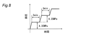
- FIG. 8 is a schematic view of the time change of the surface pressure applied to the test shaft.
- FIG. 9 is a diagram showing the seizure surface pressure of the test shaft in relation to the room temperature thermal conductivity of the quench hardened layer.
- the present inventors have studied to further increase the thermal conductivity of the crankshaft to improve seizure resistance.
- the present inventors have focused on the fact that the smaller the amount of the solid solution element, the higher the thermal conductivity, and if the total amount of the solid solution amount of the alloy element in the quenching hardened layer is limited to a predetermined value or less, the present inventors will be more than before. It was clarified that excellent seizure resistance can be obtained.
- Mn is an element that improves the hardenability of steel, so if the Mn content is reduced, the fatigue strength cannot be guaranteed.
- the inventors of the present invention can obtain excellent seizure resistance while ensuring hardenability by containing a small amount of Mo and B instead of reducing the Mn content and further containing an appropriate amount of Ti. Found.
- crankshaft according to this embodiment has the chemical composition described below.
- "%" of elemental content means% by mass, unless otherwise noted.
- C 0.35 to 0.50% Carbon (C) improves the hardness of steel and contributes to the improvement of fatigue strength. On the other hand, if the C content is too high, the shrinkage resistance and machinability are lowered. Therefore, the C content is 0.35 to 0.50%.
- the lower limit of the C content is preferably 0.36%, more preferably 0.37%.
- the upper limit of the C content is preferably 0.45%, more preferably 0.40%.
- Si Silicon
- the Si content is preferably as low as possible and is limited to 0.55% or less in this embodiment. Since Si has a smaller atomic weight than Mn, it has a greater effect on thermal conductivity than Mn.
- the Si content is preferably 0.20% or less, more preferably 0.10% or less, more preferably 0.05% or less, still more preferably 0.02% or less.
- Mn 0.01 to 0.55%
- Mn Manganese
- the Mn content is preferably as low as possible in order to improve the thermal conductivity.
- the Mn content is very low, S may react with Fe to cause brittle cracking. Therefore, the Mn content is 0.01 to 0.55%.
- the lower limit of the Mn content is preferably 0.20%, more preferably 0.30%, further preferably 0.40%.
- the upper limit of the Mn content is preferably 0.52%, more preferably 0.50%, still more preferably 0.48%, still more preferably 0.45%.
- Chromium (Cr) enhances the hardenability of steel. On the other hand, if the Cr content is too high, the thermal conductivity of the steel will decrease. Therefore, the Cr content is 0.10 to 0.50%.
- the lower limit of the Cr content is preferably 0.05%, more preferably 0.10%.
- the upper limit of the Cr content is preferably 0.40%, more preferably 0.30%, further preferably 0.25%, further preferably 0.20%.
- P 0.03% or less Phosphorus (P) is an impurity. P reduces the quench cracking resistance of steel. Therefore, the lower the P content, the more preferable, and in the present embodiment, the P content is limited to 0.03% or less.
- the P content is preferably 0.025% or less, more preferably 0.02% or less.
- S 0.10% or less Sulfur (S) reduces the hot workability of steel. Further, when the Mn content is very low, S may react with Fe to cause brittle cracking. Therefore, in this embodiment, the S content is limited to 0.10% or less. On the other hand, S forms MnS and MnS 2 in the steel to reduce the amount of solid solution Mn. Further, since MnS is soft and brittle, it has an effect of improving the machinability of the crankshaft, particularly the machinability. Therefore, depending on the Mn content, a small amount of S may be positively contained.
- the lower limit of the S content is preferably 0.010%, more preferably 0.020%, further preferably 0.030%, still more preferably 0.040%, still more preferably 0. It is 0.045%.
- the upper limit of the S content is preferably 0.070%, more preferably 0.065%.
- Mo 0.10 to 0.30% Molybdenum (Mo) improves the hardenability of steel.
- 0.10% or more of Mo is contained in order to compensate for the decrease in hardenability due to the limitation of the Mn content. Since Mo has a larger atomic weight than Mn, its influence on thermal conductivity is smaller than that of Mn. However, if it is contained in excess of 0.30%, it becomes difficult to secure the required thermal conductivity. Therefore, the Mo content is 0.10 to 0.30%.
- the lower limit of the Mo content is preferably 0.12%, more preferably 0.14%.
- the upper limit of the Mo content is preferably 0.25%, more preferably 0.20%, further preferably 0.18%.
- B 0.0020 to 0.0050% Boron (B) improves the hardenability of steel.
- B Boron (B) improves the hardenability of steel.
- 0.0020% or more of B is contained in order to compensate for the decrease in hardenability due to the limitation of the Mn content.
- the B content is 0.0020 to 0.0050%.
- the lower limit of the B content is preferably 0.0023%, more preferably 0.0025%.
- the upper limit of the B content is preferably 0.0040%, more preferably 0.0030%.
- Ti 0.020-0.10% Titanium (Ti) forms TiN and fixes N in steel. As a result, B is suppressed from forming BN, and the hardenability improving effect of B is ensured. On the other hand, if the Ti content is too high, TiN is excessively formed and the machinability is lowered. Therefore, the Ti content is 0.020 to 0.10%.
- the lower limit of the Ti content is preferably 0.023%, more preferably 0.025%.
- the upper limit of the Ti content is preferably 0.050%, more preferably 0.040%, still more preferably 0.030%.
- N 0.020% or less Nitrogen (N) is an impurity. N reacts with B and hinders the hardenability improving effect of B. N further forms a nitride to reduce machinability and fatigue strength. Therefore, the lower the N content, the more preferable, and in the present embodiment, the N content is limited to 0.020% or less.
- the upper limit of the N content is preferably 0.010%, more preferably 0.005%, still more preferably 0.004%. On the other hand, if the N content is extremely reduced, the cost will increase.
- the lower limit of the N content is preferably 0.001%.
- Al 0.10% or less
- Aluminum (Al) is an impurity. Al forms inclusions and nitrides, and reduces machinability and fatigue strength. Therefore, the smaller the Al content, the more preferable, and in this embodiment, the content is limited to 0.10% or less.
- the upper limit of the Al content is preferably 0.010%, more preferably 0.005%, further preferably 0.004%. On the other hand, if the Al content is extremely reduced, the cost will increase.
- the lower limit of the Al content is preferably 0.001%.
- the balance of the chemical composition of the crankshaft according to the present embodiment is Fe and impurities.
- the impurities referred to here are elements mixed from ores and scraps used as raw materials for steel, or elements mixed from the environment of the manufacturing process.
- the crankshaft according to the present embodiment has a quench hardening layer on its surface.
- the quench-hardened layer preferably has a martensite ratio of 80% by volume or more.
- the martensite here includes tempered martensite.
- the crankshaft according to the present embodiment may have a hardened hardened layer formed only on the surface, or may be hardened to the core.
- the thickness of the region where the martensite ratio is 80% by volume or more is preferably 1.0 mm or more.
- the proportion of martensite in the region from the surface of the crankshaft to 1.0 mm is preferably 90% by volume or more, more preferably 95% by volume or more, and further preferably 99% by volume or more.
- the thickness of the region where the proportion of martensite is 80% by volume or more is more preferably 2.0 mm or more, still more preferably 3.0 mm or more.
- the hardened layer does not have to be formed on the entire crankshaft, but may be formed only on a part (for example, a pin or a journal part).
- Si, Mn, Cr, and Mo solid-dissolved in the quench-hardened layer satisfy the following formula (1). 1.960Si M +1.002 Mn M +1.059Cr M +0.574Mo M ⁇ 0.75 (1) The amounts of Si, Mn, Cr, and Mo dissolved in the hardened layer are substituted in mass% for Si M , Mn M , Cr M , and Mo M in the formula (1), respectively.
- Si, Mn, Cr, Mo, C, S, B, Ti, and N solidly dissolved in the hardened layer preferably satisfy the following formula (2). 1.960Si M +1.002Mn M +1.059Cr M +0.574Mo M +4.585C M +1.717S M +5.094B M +1.150Ti M +3.930N M ⁇ 2.00 (2) Si M in the formula (2), Mn M, Cr M, Mo M, C M, S M, B M, Ti M, and N each of the M, Si solid-solved into the quench hardened layer, Mn, Cr , Mo, C, S, B, Ti, and N are substituted in% by mass.
- a , S A , B A , Ti A , and N A can be approximately expressed as follows.
- the atomic weights of Si, Mn, Cr, Mo, C, S, B, Ti, and N are 28.09, 54.94, 52.00, 95.94, 12.01, 32.07, and 10, respectively. Calculated as .81, 47.88, and 14.01.
- the value on the left side of the formula (1) is set to 0.75 or less, high thermal conductivity can be obtained and excellent seizure resistance can be obtained.
- the value on the left side of the formula (1) is preferably 0.73 or less, more preferably 0.71 or less, still more preferably 0.70 or less, still more preferably 0.68 or less.
- the left side of Expression (2) is set to 2.00 or less.
- the value on the left side of the formula (2) is more preferably 1.98 or less, still more preferably 1.95 or less, further preferably 1.93 or less, and further preferably 1.90 or less.
- Si M, Mn M, Cr M , Mo M, C M, S M, B M, Ti M, and N M is measured as follows.
- FIG. 1 is a flow chart of a method for analyzing Mn, Cr, Mo, Ti, and Si from the electrolytic extraction residue.
- a sample for measuring the electrolytic extraction residue is collected from the portion where the quenching hardened layer is formed.
- the sample to be collected can have a cylindrical shape with a height of 12.0 mm and a diameter of 47.9 mm obtained by cutting out a part of the sample.
- the cross section of this sample is masked to dissolve only the surface layer.
- AA solution acetylacetone-1% by mass tetramethylammonium chloride / methanol solution
- AA electrolysis a 10% by mass acetylacetone-1% by mass tetramethylammonium chloride / methanol solution
- the solution is filtered through a filter with a pore size of 0.2 ⁇ m. Dissolve the filter with acid and collect the residue.
- the recovered residue is decomposed by an acid decomposition method. Specifically, a mixed acid containing H 2 SO 4 , HNO 3 , H 3 PO 4 , HCl O 4 and H 2 O is used, and the mixture is heated at 350 ° C. for 1 hour.
- the masses of Mn, Cr, Mo, and Ti are quantified by ICP emission spectroscopy.
- Fig. 2 is a flow chart of the method for analyzing S from the electrolytic extraction residue.
- the measurement of Mn, Cr, Mo, and Ti is the same as the measurement of the residue obtained by filtering the AA-electrolyzed solution with a filter having a pore size of 0.2 ⁇ m to recover the residue and subjecting the recovered residue to acid decomposition.
- the acid-decomposed solution is further filtered through a filter having a pore size of 0.2 ⁇ m, the residue not decomposed by acid decomposition is recovered, and the mass of S is quantified by distillation separation methylene blue absorptiometry.
- the distillative separation methylene blue absorption method shall be performed in accordance with JIS G 1215.
- FIG. 3 is a flow chart of the method for analyzing B from the electrolytic extraction residue.
- the measurement of Mn, Cr, Mo, and Ti is the same as the measurement of the residue obtained by filtering the AA-electrolyzed solution with a filter having a pore size of 0.2 ⁇ m to recover the residue and subjecting the recovered residue to acid decomposition.
- the acid-decomposed solution is further distilled. Distillation shall be performed in accordance with JIS G 1227, Annex 2. After distillation, the mass of B is quantified by ICP emission spectroscopy, not according to JIS G 1227.
- FIG. 4 is a flow chart of the method for analyzing N from the electrolytic extraction residue.
- the measurement of Mn, Cr, Mo, and Ti is the same as the measurement of the residue obtained by filtering the AA-electrolyzed solution with a filter having a pore size of 0.2 ⁇ m to recover the residue and subjecting the recovered residue to acid decomposition.
- the mass of N is quantified by distillative separation amide-sulfuric acid titration method for the acid decomposed solution. This method shall be performed in accordance with JIS G 1228 Annex 1.
- FIG. 5 is a flow chart of a method for analyzing C from the electrolytic extraction residue.
- the AA-electrolyzed solution is filtered through a glass filter having a pore size of 0.2 ⁇ m to recover the residue, and the mass of C is quantified by the high frequency combustion infrared absorption method.
- the high-frequency combustion infrared absorption method is performed according to b) of 8.2 (quantitative operation) of JIS G 1211-3: 2018 (iron and steel-carbon quantification method-).
- JIS Z 2615 2015 8.13. (Add pure iron)) to burn to CO and CO 2 carbon on the glass filter.
- the detected amounts of CO and CO 2 are integrated, and the integrated amount is compared with a calibration curve obtained in advance to obtain the carbon amount.
- Si M, Mn M, Cr M , Mo M, C M, S M, B M, Ti M, and N M, respectively, can be adjusted by the chemical composition of the steel material. That, Si in the steel, Mn, Cr, Mo, C , S, B, if lowering the content of Ti, and N, Si M, Mn M, Cr M, Mo M, C M, S M, B M, Ti M, and also N M decreases.
- Si M , Mn M , Cr M , and Mo M also vary with precipitates and inclusions. Therefore, it varies depending on the content of C, N, S that reacts with these elements and the heat treatment. For example, when the S content is high, Mn and S react with each other to precipitate MnS and MnS 2 , and Mn M tends to be small. Further, for example, if the residence time at around 600 ° C. is lengthened during cooling from hot working, or if tempering is performed in this temperature range, carbides are precipitated and Cr M and Mo M are reduced. Further, when cementite is precipitated, Mn and Cr form a solid solution with cementite, so that the values of Mn M and Cr M become small.
- crankshaft according to the present embodiment preferably has an ideal critical diameter Di of 1.7 or more calculated from the chemical composition according to ASTM A255-67.
- the ideal critical diameter Di is the critical diameter (50% martensite in the center) when quenching with a quenching solution having ideal cooling capacity (a quenching solution in which the surface temperature of steel becomes the temperature of the solution at the moment of quenching).
- the diameter of the steel material to be used. The unit is inch.) and is used as an index of hardenability.
- the ideal critical diameter Di is 1.7 or more, the hardenability required to secure the fatigue strength required for the crankshaft can be obtained.
- the ideal critical diameter Di is more preferably 1.9 or more, more preferably 2.0 or more, more preferably 2.1 or more, and even more preferably 2.2 or more.
- the ideal critical diameter Di is calculated from the crankshaft chemical composition according to ASTM A255-67 as follows.
- Di the product of Di (provisional) and the following boron factor (Bolon F) is defined as Di.
- Di provisional
- Bolon F 2.616-1.6 ⁇ C
- the C content is substituted into C in the above formula in mass%.
- the crankshaft according to this embodiment preferably has a hardened hardened layer having a thermal conductivity of 45 W / m ⁇ K or more at room temperature.
- Thermal conductivity is measured as follows. A disk-shaped sample having an outer diameter of 10 mm and a thickness of 1 mm is taken from the quench-hardened layer. The density of the sample is calculated from the volume and mass of the sample. The specific heat and thermal diffusivity of the sample are obtained by the laser flash method specified in JIS R 1611. The thermal conductivity of the sample is determined as the product of density, specific heat and thermal diffusivity.
- crankshaft manufacturing method Hereinafter, an example of the method for manufacturing the crankshaft according to the present embodiment will be described.
- the manufacturing method described below is merely an example, and does not limit the manufacturing method of the crankshaft according to the present embodiment.
- the material is, for example, steel bar.
- the raw material can be produced, for example, by continuously casting or slabbing molten steel having the above chemical composition.
- the material is hot forged to give a rough shape to the crankshaft.
- the hot forging may be performed separately in rough forging and finish forging. If necessary, heat treatment such as normalizing may be performed on the rough crankshaft product manufactured by hot forging.
- Machining rough crankshaft products. Machining includes cutting, grinding, and drilling. By this process, an intermediate product having a shape close to that of the final product is produced.
- a hardened layer is formed on the surface. Specifically, it is heated to a predetermined heating temperature and then rapidly cooled.
- the high-frequency induction heating device may be used to locally heat the intermediate product, or the heat treatment furnace may be used to heat the entire intermediate product.
- the heating temperature is preferably Ac 3 points or more, and more preferably 900 ° C. or more.
- tempering may be carried out if necessary. Quenching and tempering may be performed a plurality of times, and other heat treatments may be performed in addition to the quenching and tempering.
- finish processing is performed on the intermediate product on which the quench-hardened layer has been formed.
- the journal and pins of the crankshaft are ground and wrapped to adjust the surface shape.
- the crankshaft according to the present embodiment can be manufactured through the above steps.
- crankshaft according to the embodiment of the present invention has been described above. According to this embodiment, a crankshaft having excellent seizure resistance can be obtained.
- a test shaft for a seizure test was made from steel having the chemical composition shown in Table 1.
- FIG. 6 shows a heat pattern when the test shaft is manufactured.
- the material was heated at 1250 ° C. for 1 hour, then hot forged at 1100 to 850 ° C., and after the forging was completed, allowed to cool to room temperature. Then, after normalizing by heating at 1250 ° C. for 20 minutes and then air-cooling, the outer diameter was adjusted to 47.9 mm by machining (cutting). Then, induction hardening was carried out to form a hardened layer having a surface hardness of HV650.
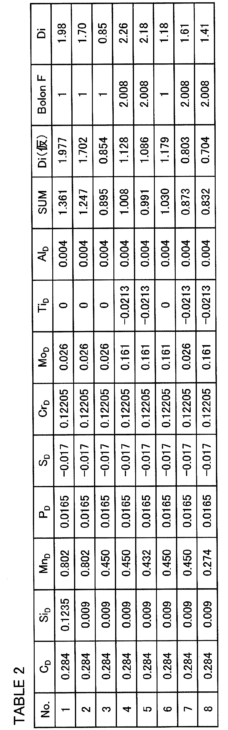
- the hardenability of the material was evaluated by the ideal critical diameter Di. Specifically, if the ideal critical diameter Di is 1.7 or more, which is about 90% of the conventional steel (Di ⁇ 1.98), it is determined that the crankshaft has the necessary hardenability. In the calculation of Di, Si of less than 0.002% by mass, Mn of less than 0.002% by mass, and Mo of less than 0.002% by mass were all treated as 0%. Table 2 shows the calculation progress of Di.
- Si Mn, Cr, Mo, C, S, B, Ti, and N were measured. If the Si content is less than 0.002% by mass, Si M is 0%, if the Mn content is less than 0.002% by mass, Mn M is 0%, and if the Mo content is less than 0.002% by mass. was treated Mo M 0%, is the B M 0% that of the B content is less than 0.0002 mass%, 0% is Ti M those of Ti content is less than 0.002 mass%. On the other hand, with respect to a small atomic weight N, to determine the N M without treating even 0% that of 0.0040 wt%.
- the thermal conductivity of the base material (portion other than the quench-hardened layer) and the quench-hardened layer was measured.
- test shafts 4 and 5 had an ideal critical diameter Di equivalent to that of the conventional steel (No. 1), and had a high thermal conductivity of 45 W / mK or more.
- test shaft of No. 2 had a hardenability within the allowable range, but No.
- the thermal conductivity was inferior to that of 4 and 5. This is probably because the amount of solute Mn was too large.
- test shaft of No. 3 had high thermal conductivity, but was inferior in hardenability. This is No. It is probable that the test shaft of No. 6 did not contain Mo and B.
- test shaft of No. 6 had high thermal conductivity, but was inferior in hardenability. This is No. It is probable that the test shaft of No. 6 did not contain B.
- test shaft of No. 7 had high thermal conductivity, but was inferior in hardenability. This is No. It is considered that the test shaft of No. 7 did not contain Mo.
- test shaft of No. 8 had high thermal conductivity, but was inferior in hardenability. This is No. It is probable that the Mn content of the test shaft of No. 8 was too low.
- test shafts No. A seizure test was performed using 2, 4, and 5 test shafts.
- the test shaft to be subjected to the seizure test was ground and wrapped so that the arithmetic average height Pa of the cross-sectional curve was 0.07 to 0.09 ⁇ m as a finishing process.
- the outer diameter of the test shaft was adjusted so that the clearance with the bearing used in the seizure test described later was about 0.090 mm.
- the seizure test was performed using a crank metal wear and seizure resistance evaluation device manufactured by Shinko Machinery Co., Ltd.
- a schematic diagram of the evaluation device 20 is shown in FIG.
- the test shaft TP was inserted into a plurality of bearings 21, and the test shaft TP was rotated at 8000 rpm by a motor (not shown) while lubricating the bearings 21.
- As the metal of the bearing an Al alloy of HV40 to 50 was used.
- the lubricating oil was 0W-20, the oil supply temperature was 140° C., and the oil pressure was 0.8 MPa.
- FIG. 8 schematically shows the time change of the surface pressure applied to the test axis TP.
- the holding time at the same surface pressure was 3 minutes, the increase width of the surface pressure per step was 4.35 MPa, and the time taken to increase the surface pressure was 15 seconds. It was determined that seizure occurred when the surface temperature of the test shaft TP was 280 ° C. or higher or the torque applied to the test shaft was 25 Nm or higher. The test was carried out three times on each test shaft, and the average value was taken as the seizure surface pressure.
- FIG. 9 is a diagram showing the seizure surface pressure of the test shaft in relation to the room temperature thermal conductivity of the quench hardened layer. As shown in FIG. 9, No. 1 having high thermal conductivity. The test axes of Nos. 4 and 5 are No. It was confirmed to have excellent seizure resistance as compared with the No. 2 test shaft.
- the above-described embodiment is merely an example for carrying out the present invention. Therefore, the present invention is not limited to the above-described embodiment, and the above-described embodiment can be appropriately modified and implemented within a range that does not deviate from the gist thereof.
Landscapes
- Chemical & Material Sciences (AREA)
- Engineering & Computer Science (AREA)
- Mechanical Engineering (AREA)
- Materials Engineering (AREA)
- Metallurgy (AREA)
- Organic Chemistry (AREA)
- Thermal Sciences (AREA)
- General Engineering & Computer Science (AREA)
- Physics & Mathematics (AREA)
- Crystallography & Structural Chemistry (AREA)
- Ocean & Marine Engineering (AREA)
- Shafts, Cranks, Connecting Bars, And Related Bearings (AREA)
- Heat Treatment Of Articles (AREA)
Abstract
耐焼付き性に優れたクランクシャフトを提供する。クランクシャフトは、化学組成が、質量%で、C:0.35~0.50%、Si:0.55%以下、Mn:0.01~0.55%、Cr:0.10~0.50%、P:0.03%以下、S:0.10%以下、Mo:0.10~0.30%、B:0.0020~0.0050%、Ti:0.020~0.10%、N:0.020%以下、Al:0.10%以下、残部:Fe及び不純物であり、焼入れ硬化層を表面に有し、焼入れ硬化層へ固溶したSi、Mn、Cr、及びMoが、下記の式(1)を満たす。 1.960SiM+1.002MnM+1.059CrM+0.574MoM≦0.75 (1) 式(1)中のSiM、MnM、CrM、及びMoMにはそれぞれ、焼入れ硬化層へ固溶したSi、Mn、Cr、及びMoの量が質量%で代入される。
Description
本発明は、クランクシャフトに関し、より詳しくは、焼入れ硬化層を有するクランクシャフトに関する。
耐摩耗性や疲労強度を向上させるため、表面に焼入れ硬化層を形成したクランクシャフトが知られている。例えば特許第4910654号公報には、クランク・ピンの表面に焼入れ硬化層を有するクランクシャフトであって、クランク・ピンのボトムR部における表面残留圧縮応力が600MPa以上であるクランクシャフトが開示されている。
クランクシャフトに関するものではないが、高周波焼入れされて使用される鋼材に関する文献として、特開平11-217649号公報には、冷間加工性と高強度特性とを兼備した高周波焼入れ用鋼材が開示されている。また、国際公開第2004/035848号には、転造性、耐焼割性及びねじり特性に優れた機械構造用鋼材が開示されている。
近年、自動車の省燃費化ニーズを背景に、クランクシャフトの軽量化や潤滑油の低粘度化が進んでいる。そのため、クランクシャフトと軸受けとの摺動条件は過酷になっており、クランクシャフトには従来よりも優れた耐焼付き性が求められている。
クランクシャフトの熱伝導率を高くすることで、潤滑油の温度上昇に伴う粘度の低下を抑制して、耐焼付き性を向上できることが知られている。また、Si含有量を低減することで、クランクシャフトの熱伝導率を高くできることも知られている。
特許第4589885号公報には、Si:0.15%以下、Mn:1.0%を超えて2.0%以下等を含有し、熱伝導率が40W/mK以上であって、かつ高周波焼入れ後の表面硬さHvと熱伝導率κとがHv>2.7×κ+420の関係を満足するクランクシャフトが開示されている。
国際公開第2012/029395号には、Si:0.20%以下、Mn:0.75~2.0%、Cr:0.05~1.2%等を含有し、さらにMn及びCr含有量の合計を1.20~2.10%にした高周波焼入れ用鋼が開示されている。
特開2017-61747号公報には、Si:0.50%未満、Mn:0.70%未満、Mo:0.5~3.5%、S:0.05~0.1%等を含有する摺動部品が開示されている。
クランクシャフトには一層の軽量化が求められており、摺動条件はさらに過酷になることが予測される。本発明の目的は、耐焼付き性に優れたクランクシャフトを提供することである。
本発明の一実施形態によるクランクシャフトは、化学組成が、質量%で、C:0.35~0.50%、Si:0.55%以下、Mn:0.01~0.55%、Cr:0.10~0.50%、P:0.03%以下、S:0.10%以下、Mo:0.10~0.30%、B:0.0020~0.0050%、Ti:0.020~0.10%、N:0.020%以下、Al:0.10%以下、残部:Fe及び不純物であり、焼入れ硬化層を表面に有し、前記焼入れ硬化層へ固溶したSi、Mn、Cr、及びMoが、下記の式(1)を満たす。
1.960SiM+1.002MnM+1.059CrM+0.574MoM≦0.75 (1)
式(1)中のSiM、MnM、CrM、及びMoMにはそれぞれ、前記焼入れ硬化層へ固溶したSi、Mn、Cr、及びMoの量が質量%で代入される。
1.960SiM+1.002MnM+1.059CrM+0.574MoM≦0.75 (1)
式(1)中のSiM、MnM、CrM、及びMoMにはそれぞれ、前記焼入れ硬化層へ固溶したSi、Mn、Cr、及びMoの量が質量%で代入される。
本発明によれば、耐焼付き性に優れたクランクシャフトが得られる。
本発明者らは、クランクシャフトの熱伝導率をさらに高めて、耐焼付き性を向上させることを検討した。本発明者らは、固溶元素の量が少ないほど熱伝導率が向上することに着目し、焼入れ硬化層への合金元素の固溶量の総和を所定値以下に制限すれば、従来よりも優れた耐焼付き性が得られることを明らかにした。
一方、Mnは鋼材の焼入れ性を向上させる元素であるため、Mn含有量を低減すると、疲労強度を担保できない。本発明者らは、Mn含有量を低減する代わりに、少量のMo及びBを含有させ、さらに適量のTiを含有させることで、焼入れ性を確保しつつ、優れた耐焼付き性が得られることを見出した。
本発明は、以上の知見に基づいて完成された。以下、本発明の一実施形態によるクランクシャフトについて詳述する。
[化学組成]
本実施形態によるクランクシャフトは、以下に説明する化学組成を有する。以下の説明において、元素の含有量の「%」は、他に断りがない限り、質量%を意味する。
本実施形態によるクランクシャフトは、以下に説明する化学組成を有する。以下の説明において、元素の含有量の「%」は、他に断りがない限り、質量%を意味する。
C:0.35~0.50%
炭素(C)は、鋼の硬さを向上させ、疲労強度の向上に寄与する。一方、C含有量が高すぎると、耐焼割れ性及び被削性が低下する。したがって、C含有量は0.35~0.50%である。C含有量の下限は、好ましくは0.36%であり、さらに好ましくは0.37%である。C含有量の上限は、好ましくは0.45%であり、さらに好ましくは0.40%である。
炭素(C)は、鋼の硬さを向上させ、疲労強度の向上に寄与する。一方、C含有量が高すぎると、耐焼割れ性及び被削性が低下する。したがって、C含有量は0.35~0.50%である。C含有量の下限は、好ましくは0.36%であり、さらに好ましくは0.37%である。C含有量の上限は、好ましくは0.45%であり、さらに好ましくは0.40%である。
Si:0.55%以下
シリコン(Si)は、マトリクスに固溶して鋼の熱伝導率を低下させる。Si含有量はできるだけ低くすることが好ましく、本実施形態では0.55%以下に制限する。Siは、Mnに比べて原子量が小さいため、熱伝導率への影響がMnに比べて大きい。Si含有量は、好ましくは0.20%以下であり、より好ましくは0.10%以下であり、より好ましくは0.05%以下であり、さらに好ましくは0.02%以下である。
シリコン(Si)は、マトリクスに固溶して鋼の熱伝導率を低下させる。Si含有量はできるだけ低くすることが好ましく、本実施形態では0.55%以下に制限する。Siは、Mnに比べて原子量が小さいため、熱伝導率への影響がMnに比べて大きい。Si含有量は、好ましくは0.20%以下であり、より好ましくは0.10%以下であり、より好ましくは0.05%以下であり、さらに好ましくは0.02%以下である。
Mn:0.01~0.55%
マンガン(Mn)は、マトリクスに固溶して鋼の熱伝導率を低下させる。Mn含有量は、熱伝導率を向上させるためにはできるだけ低くすることが好ましい。一方、Mn含有量が低すぎると、オーステナイトが形成されにくくなり、焼入れ性を確保することが難しくなるため、焼入れ硬化層が形成されなくなる可能性がある。また、Mn含有量が非常に低い場合、SがFeと反応して脆性割れを起こす可能性がある。したがって、Mn含有量は、0.01~0.55%である。Mn含有量の下限は、好ましくは0.20%であり、さらに好ましくは0.30%であり、さらに好ましくは0.40%である。Mn含有量の上限は、好ましくは0.52%であり、さらに好ましくは0.50%であり、さらに好ましくは0.48%であり、さらに好ましくは0.45%である。
マンガン(Mn)は、マトリクスに固溶して鋼の熱伝導率を低下させる。Mn含有量は、熱伝導率を向上させるためにはできるだけ低くすることが好ましい。一方、Mn含有量が低すぎると、オーステナイトが形成されにくくなり、焼入れ性を確保することが難しくなるため、焼入れ硬化層が形成されなくなる可能性がある。また、Mn含有量が非常に低い場合、SがFeと反応して脆性割れを起こす可能性がある。したがって、Mn含有量は、0.01~0.55%である。Mn含有量の下限は、好ましくは0.20%であり、さらに好ましくは0.30%であり、さらに好ましくは0.40%である。Mn含有量の上限は、好ましくは0.52%であり、さらに好ましくは0.50%であり、さらに好ましくは0.48%であり、さらに好ましくは0.45%である。
Cr:0.10~0.50%
クロム(Cr)は、鋼の焼入れ性を高める。一方、Cr含有量が高すぎると、鋼の熱伝導率が低下する。したがって、Cr含有量は0.10~0.50%である。Cr含有量の下限は、好ましくは0.05%であり、さらに好ましくは0.10%である。Cr含有量の上限は、好ましくは0.40%であり、さらに好ましくは0.30%であり、さらに好ましくは0.25%であり、さらに好ましくは0.20%である。
クロム(Cr)は、鋼の焼入れ性を高める。一方、Cr含有量が高すぎると、鋼の熱伝導率が低下する。したがって、Cr含有量は0.10~0.50%である。Cr含有量の下限は、好ましくは0.05%であり、さらに好ましくは0.10%である。Cr含有量の上限は、好ましくは0.40%であり、さらに好ましくは0.30%であり、さらに好ましくは0.25%であり、さらに好ましくは0.20%である。
P:0.03%以下
リン(P)は、不純物である。Pは、鋼の耐焼割れ性を低下させる。したがって、P含有量は低いほど好ましく、本実施形態では0.03%以下に制限する。P含有量は、好ましくは0.025%以下であり、さらに好ましくは0.02%以下である。
リン(P)は、不純物である。Pは、鋼の耐焼割れ性を低下させる。したがって、P含有量は低いほど好ましく、本実施形態では0.03%以下に制限する。P含有量は、好ましくは0.025%以下であり、さらに好ましくは0.02%以下である。
S:0.10%以下
硫黄(S)は、鋼の熱間加工性を低下させる。また、Mn含有量が非常に低い場合、SがFeと反応して脆性割れを起こす可能性がある。そのため本実施形態では、S含有量を0.10%以下に制限する。一方でSは、鋼中にMnSやMnS2を形成し、固溶Mn量を低減させる。さらに、MnSは柔らかくて脆いため、クランクシャフトの機械加工性、特に被削性を向上させる効果を持つ。そのため、Mn含有量によっては、少量のSを積極的に含有させてもよい。S含有量の下限は、好ましくは0.010%であり、さらに好ましくは0.020%であり、さらに好ましくは0.030%であり、さらに好ましくは0.040%であり、さらに好ましくは0.045%である。S含有量の上限は、好ましくは0.070%であり、さらに好ましくは0.065%である。
硫黄(S)は、鋼の熱間加工性を低下させる。また、Mn含有量が非常に低い場合、SがFeと反応して脆性割れを起こす可能性がある。そのため本実施形態では、S含有量を0.10%以下に制限する。一方でSは、鋼中にMnSやMnS2を形成し、固溶Mn量を低減させる。さらに、MnSは柔らかくて脆いため、クランクシャフトの機械加工性、特に被削性を向上させる効果を持つ。そのため、Mn含有量によっては、少量のSを積極的に含有させてもよい。S含有量の下限は、好ましくは0.010%であり、さらに好ましくは0.020%であり、さらに好ましくは0.030%であり、さらに好ましくは0.040%であり、さらに好ましくは0.045%である。S含有量の上限は、好ましくは0.070%であり、さらに好ましくは0.065%である。
Mo:0.10~0.30%
モリブデン(Mo)は、鋼の焼入れ性を向上させる。本実施形態ではMn含有量を制限することによる焼入れ性の低下を補うため、0.10%以上のMoを含有させる。Moは、Mnに比べて原子量が大きいため、熱伝導率への影響がMnと比べて小さい。しかし、0.30%を超えて含有させると、必要な熱伝導率を確保することが困難になる。したがって、Mo含有量は、0.10~0.30%である。Mo含有量の下限は、好ましくは0.12%であり、さらに好ましくは0.14%である。Mo含有量の上限は、好ましくは0.25%であり、さらに好ましくは0.20%であり、さらに好ましくは0.18%である。
モリブデン(Mo)は、鋼の焼入れ性を向上させる。本実施形態ではMn含有量を制限することによる焼入れ性の低下を補うため、0.10%以上のMoを含有させる。Moは、Mnに比べて原子量が大きいため、熱伝導率への影響がMnと比べて小さい。しかし、0.30%を超えて含有させると、必要な熱伝導率を確保することが困難になる。したがって、Mo含有量は、0.10~0.30%である。Mo含有量の下限は、好ましくは0.12%であり、さらに好ましくは0.14%である。Mo含有量の上限は、好ましくは0.25%であり、さらに好ましくは0.20%であり、さらに好ましくは0.18%である。
B:0.0020~0.0050%
ホウ素(B)は、鋼の焼入れ性を向上させる。本実施形態ではMn含有量を制限することによる焼入れ性の低下を補うため、0.0020%以上のBを含有させる。一方、0.0050%を超えて含有させても、焼入れ性向上効果が飽和するとともに、鋼の熱間加工性が低下する。したがって、B含有量は、0.0020~0.0050%である。B含有量の下限は、好ましくは0.0023%であり、さらに好ましくは0.0025%である。B含有量の上限は、好ましくは0.0040%であり、さらに好ましくは0.0030%である。
ホウ素(B)は、鋼の焼入れ性を向上させる。本実施形態ではMn含有量を制限することによる焼入れ性の低下を補うため、0.0020%以上のBを含有させる。一方、0.0050%を超えて含有させても、焼入れ性向上効果が飽和するとともに、鋼の熱間加工性が低下する。したがって、B含有量は、0.0020~0.0050%である。B含有量の下限は、好ましくは0.0023%であり、さらに好ましくは0.0025%である。B含有量の上限は、好ましくは0.0040%であり、さらに好ましくは0.0030%である。
Ti:0.020~0.10%
チタン(Ti)は、TiNを形成して鋼中のNを固定する。これによって、BがBNを形成するのを抑制して、Bによる焼入れ性向上効果を担保する。一方、Ti含有量が高すぎると、TiNが過剰に形成されて被削性が低下する。したがって、Ti含有量は0.020~0.10%である。Ti含有量の下限は、好ましくは0.023%であり、さらに好ましくは0.025%である。Ti含有量の上限は、好ましくは0.050%であり、さらに好ましくは0.040%であり、さらに好ましくは0.030%である。
チタン(Ti)は、TiNを形成して鋼中のNを固定する。これによって、BがBNを形成するのを抑制して、Bによる焼入れ性向上効果を担保する。一方、Ti含有量が高すぎると、TiNが過剰に形成されて被削性が低下する。したがって、Ti含有量は0.020~0.10%である。Ti含有量の下限は、好ましくは0.023%であり、さらに好ましくは0.025%である。Ti含有量の上限は、好ましくは0.050%であり、さらに好ましくは0.040%であり、さらに好ましくは0.030%である。
N:0.020%以下
窒素(N)は、不純物である。Nは、Bと反応してBによる焼入れ性向上効果を妨げる。Nはさらに、窒化物を形成して被削性や疲労強度を低下させる。したがって、N含有量は低いほど好ましく、本実施形態では0.020%以下に制限する。N含有量の上限は、好ましくは0.010%であり、さらに好ましくは0.005%であり、さらに好ましくは0.004%である。一方、N含有量を極端に低減しようとするとコストの上昇を招く。N含有量の下限は、好ましくは0.001%である。
窒素(N)は、不純物である。Nは、Bと反応してBによる焼入れ性向上効果を妨げる。Nはさらに、窒化物を形成して被削性や疲労強度を低下させる。したがって、N含有量は低いほど好ましく、本実施形態では0.020%以下に制限する。N含有量の上限は、好ましくは0.010%であり、さらに好ましくは0.005%であり、さらに好ましくは0.004%である。一方、N含有量を極端に低減しようとするとコストの上昇を招く。N含有量の下限は、好ましくは0.001%である。
Al:0.10%以下
アルミニウム(Al)は、不純物である。Alは、介在物や窒化物を形成し、被削性や疲労強度を低下させる。したがって、Al含有量は少ないほど好ましく、本実施形態では0.10%以下に制限する。Al含有量の上限は、好ましくは0.010%であり、さらに好ましくは0.005%であり、さらに好ましくは0.004%である。一方、Al含有量を極端に低減しようとするとコストの上昇を招く。Al含有量の下限は、好ましくは0.001%である。
アルミニウム(Al)は、不純物である。Alは、介在物や窒化物を形成し、被削性や疲労強度を低下させる。したがって、Al含有量は少ないほど好ましく、本実施形態では0.10%以下に制限する。Al含有量の上限は、好ましくは0.010%であり、さらに好ましくは0.005%であり、さらに好ましくは0.004%である。一方、Al含有量を極端に低減しようとするとコストの上昇を招く。Al含有量の下限は、好ましくは0.001%である。
本実施形態によるクランクシャフトの化学組成の残部は、Fe及び不純物である。ここでいう不純物は、鋼の原料として利用される鉱石やスクラップから混入する元素、あるいは製造過程の環境等から混入する元素をいう。
[焼入れ硬化層]
本実施形態によるクランクシャフトは、焼入れ硬化層を表面に有する。焼入れ硬化層は、マルテンサイトの割合が80体積%以上であることが好ましい。ここでいうマルテンサイトは、焼戻しマルテンサイトを含む。
本実施形態によるクランクシャフトは、焼入れ硬化層を表面に有する。焼入れ硬化層は、マルテンサイトの割合が80体積%以上であることが好ましい。ここでいうマルテンサイトは、焼戻しマルテンサイトを含む。
本実施形態によるクランクシャフトは、焼入れ硬化層が表面だけに形成されたものであってもよいし、芯部まで焼入れたものであってもよい。焼入れ硬化層を表面だけに形成する場合、マルテンサイトの割合が80体積%以上である領域の厚さが1.0mm以上であることが好ましい。この場合、クランクシャフトの表面から1.0mmまでの領域のマルテンサイトの割合は、好ましくは90体積%以上であり、より好ましくは95体積%以上であり、さらに好ましくは99体積%以上である。マルテンサイトの割合が80体積%以上である領域の厚さは、より好ましくは2.0mm以上であり、さらに好ましくは3.0mm以上である。焼入れ硬化層は、クランクシャフトの全体に形成されている必要はなく、一部(例えばピンやジャーナルの部分)だけに形成されていてもよい。
[焼入れ硬化層への固溶量]
本実施形態によるクランクシャフトは、焼入れ硬化層へ固溶したSi、Mn、Cr、及びMoが、下記の式(1)を満たす。
1.960SiM+1.002MnM+1.059CrM+0.574MoM≦0.75 (1)
式(1)中のSiM、MnM、CrM、及びMoMにはそれぞれ、焼入れ硬化層へ固溶したSi、Mn、Cr、及びMoの量が質量%で代入される。
本実施形態によるクランクシャフトは、焼入れ硬化層へ固溶したSi、Mn、Cr、及びMoが、下記の式(1)を満たす。
1.960SiM+1.002MnM+1.059CrM+0.574MoM≦0.75 (1)
式(1)中のSiM、MnM、CrM、及びMoMにはそれぞれ、焼入れ硬化層へ固溶したSi、Mn、Cr、及びMoの量が質量%で代入される。
本実施形態によるクランクシャフトは、好ましくは、焼入れ硬化層へ固溶したSi、Mn、Cr、Mo、C、S、B、Ti、及びNが、下記の式(2)を満たす。
1.960SiM+1.002MnM+1.059CrM+0.574MoM+4.585CM+1.717SM+5.094BM+1.150TiM+3.930NM≦2.00 (2)
式(2)中のSiM、MnM、CrM、MoM、CM、SM、BM、TiM、及びNMにはそれぞれ、前記焼入れ硬化層へ固溶したSi、Mn、Cr、Mo、C、S、B、Ti、及びNの量が質量%で代入される。
1.960SiM+1.002MnM+1.059CrM+0.574MoM+4.585CM+1.717SM+5.094BM+1.150TiM+3.930NM≦2.00 (2)
式(2)中のSiM、MnM、CrM、MoM、CM、SM、BM、TiM、及びNMにはそれぞれ、前記焼入れ硬化層へ固溶したSi、Mn、Cr、Mo、C、S、B、Ti、及びNの量が質量%で代入される。
焼入れ硬化層に固溶している元素の量が多いほど、焼入れ硬化層の熱伝導率は低くなる。固溶による熱伝導率への影響は、固溶する原子の数に比例する。そのため、同じ質量であっても、原子量が小さい元素ほど熱伝導率への影響が大きくなる。したがって、固溶している元素の量は、質量%ではなく、原子%で評価することが適切である。上記の式中の1.960、1.002、1.059、0.574、4.585、1.717、5.094、1.150、及び3.930は、質量%から原子%への変換係数である。
すなわち、質量%で表されたSi、Mn、Cr、Mo、C、S、B、Ti、及びNの固溶量SiM、MnM、CrM、MoM、CM、SM、BM、TiM、及びNMと、原子%で表されたSi、Mn、Cr、Mo、C、S、B、Ti、及びNの固溶量SiA、MnA、CrA、MoA、CA、SA、BA、TiA、及びNAとの関係は、近似的に次のように表すことができる。
SiA+MnA+CrA+MoA=1.960SiM+1.002MnM+1.059CrM+0.574MoM
SiA+MnA+CrA+MoA+CA+SA+BA+TiA+NA=1.960SiM+1.002MnM+1.059CrM+0.574MoM+4.585CM+1.717SM+5.094BM+1.150TiM+3.930NM
SiA+MnA+CrA+MoA=1.960SiM+1.002MnM+1.059CrM+0.574MoM
SiA+MnA+CrA+MoA+CA+SA+BA+TiA+NA=1.960SiM+1.002MnM+1.059CrM+0.574MoM+4.585CM+1.717SM+5.094BM+1.150TiM+3.930NM
なお、原子%で表された固溶量を算出するためには、厳密には鋼材に含まれる全ての元素の物質量の総和を分母とする必要がある。しかし、本実施形態では化学組成の大部分はFeであり、他の元素の含有量が変わっても物質量の総和は大きくは変動しない。上記の係数を求めるに当たっては、鋼材100g中に含まれる物質量の総和を1.816に固定し、[原子%で表された固溶量]=100/{[各元素の原子量]×1.816}×[質量%で表された固溶量]とした。また、Si、Mn、Cr、Mo、C、S、B、Ti、及びNの原子量は、それぞれ28.09、54.94、52.00、95.94、12.01、32.07、10.81、47.88、及び14.01として計算した。
式(1)の左辺の値を0.75以下にすれば、高い熱伝導率が得られ、優れた耐焼付き性が得られる。式(1)の左辺の値は、好ましくは0.73以下であり、より好ましくは0.71以下であり、さらに好ましくは0.70以下であり、さらに好ましくは0.68以下である。本実施形態によるクランクシャフトは、より好ましくは、式(2)の左辺を2.00以下にする。式(2)の左辺の値は、より好ましくは1.98以下であり、さらに好ましくは1.95以下であり、さらに好ましくは1.93以下であり、さらに好ましくは1.90以下である。
SiM、MnM、CrM、MoM、CM、SM、BM、TiM、及びNMは、以下のように測定する。
まず、電解抽出残渣測定によって、焼入れ硬化層中の非固溶状態のSi、Mn、Cr、Mo、C、S、B、Ti、及びNの割合(質量%)を求める。図1~図5は、電解抽出残渣の分析のフロー図である。
図1は、電解抽出残渣からMn、Cr、Mo、Ti、及びSiを分析する方法のフロー図である。まず、焼入れ硬化層が形成された箇所から、電解抽出残渣測定用の試料を採取する。例えば、測定対象の鋼材が直径47.9mmの円柱形状の場合、採取する試料は、この一部を切り出した高さ12.0mm×直径47.9mmの円柱形状とすることができる。この試料の断面をマスクして、表層部だけを溶解する。具体的には、10質量%アセチルアセトン-1質量%テトラメチルアンモニウムクロライド/メタノール溶液(AA溶液)を電解液として用いた定電流電解法によって、電流密度20mA/cm2で、表面から40μmまでの部分を陽極溶解する(AA電解)。溶液を孔径0.2μmのフィルタでろ過する。酸でフィルタを溶解し、残渣を回収する。
非固溶状態のMn、Cr、Mo、及びTiの割合(質量%)を求めるため、回収した残渣を酸分解法で分解する。具体的には、H2SO4、HNO3、H3PO4、HClO4及びH2Oを含有する混酸を用いて、350℃で1時間加熱する。ICP発光分光分析法によってMn、Cr、Mo、及びTiの質量を定量する。
非固溶状態のSiの割合(質量%)を求めるため、回収した残渣をガスバーナーで1000℃以上に加熱して溶融させる。ICP発光分光分析法によって、溶融した残渣中のSiの質量を定量する。
図2は、電解抽出残渣からSを分析する方法のフロー図である。AA電解した溶液を孔径0.2μmのフィルタでろ過して残渣を回収し、回収した残渣を酸分解するところまではMn、Cr、Mo、及びTiの測定と同じである。Sの測定では、酸分解した溶液をさらに孔径0.2μmのフィルタでろ過し、酸分解で分解されなかった残渣を回収し、蒸留分離メチレンブルー吸光光度法によってSの質量を定量する。蒸留分離メチレンブルー吸光光度法は、JIS G 1215に準拠して行うものとする。
図3は、電解抽出残渣からBを分析する方法のフロー図である。AA電解した溶液を孔径0.2μmのフィルタでろ過して残渣を回収し、回収した残渣を酸分解するところまではMn、Cr、Mo、及びTiの測定と同じである。Bの測定では、酸分解した溶液をさらに蒸留する。蒸留は、JIS G 1227 附属書2に準拠して行うものとする。蒸留後は、JIS G 1227には従わず、ICP発光分光分析法によってBの質量を定量する。
図4は、電解抽出残渣からNを分析する方法のフロー図である。AA電解した溶液を孔径0.2μmのフィルタでろ過して残渣を回収し、回収した残渣を酸分解するところまではMn、Cr、Mo、及びTiの測定と同じである。Nの測定では、酸分解した溶液を蒸留分離アミド硫酸滴定法によってNの質量を定量する。この方法は、JIS G 1228 附属書1に準拠して行うものとする。
図5は、電解抽出残渣からCを分析する方法のフロー図である。Cの測定では、AA電解した溶液を孔径0.2μmのガラスフィルタでろ過して残渣を回収し、高周波燃焼赤外線吸収法によってCの質量を定量する。高周波燃焼赤外吸収法は、JIS G 1211-3:2018(鉄及び鋼-炭素定量方法-)の8.2(定量操作)のb)に準じて行う。具体的には、ガラスフィルタごと炉に入れて助燃剤(タングステンとすずの混合物(タングステン:すず=9:1)。ただし、高周波がかかりにくい場合にはJIS Z 2615:2015の8.13に準じて純鉄を加える。)と共に燃やし、ガラスフィルタ上の炭素をCO及びCO2にする。このCO、CO2の検出量を積算して、積算量を予め取得しておいた検量線と比較して炭素量を求める。
これらの質量を、電解した試料の質量で除して、非固溶状態のSi、Mn、Cr、Mo、C、S、B、Ti、及びNの割合(質量%)を求める。鋼材の化学組成のSi、Mn、Cr、Mo、C、S、B、Ti、及びNのそれぞれの含有量(質量%)と上記の値との差から、SiM、MnM、CrM、MoM、CM、SM、BM、TiM、及びNMを求める。
SiM、MnM、CrM、MoM、CM、SM、BM、TiM、及びNMはそれぞれ、鋼材の化学組成によって調整することができる。すなわち、鋼材中のSi、Mn、Cr、Mo、C、S、B、Ti、及びNの含有量を低くすれば、SiM、MnM、CrM、MoM、CM、SM、BM、TiM、及びNMも小さくなる。
SiM、MnM、CrM、及びMoMは、析出物や介在物によっても変動する。そのため、これらの元素と反応するC、N、Sの含有量や、熱処理によっても変動する。例えば、S含有量が高いと、MnとSとが反応してMnSやMnS2が析出してMnMは小さくなる傾向がある。また、例えば熱間加工からの冷却時に600℃付近での滞留時間を長くしたり、この温度域で焼戻しを実施したりすれば、炭化物が析出することによってCrM及びMoMが小さくなる。また、セメンタイトを析出させれば、Mn及びCrがセメンタイトへ固溶するため、MnM及びCrMの値は小さくなる。
[理想臨界直径]
本実施形態によるクランクシャフトは、好ましくは、ASTM A255-67に準拠して化学組成から算出される理想臨界直径Diが1.7以上である。
本実施形態によるクランクシャフトは、好ましくは、ASTM A255-67に準拠して化学組成から算出される理想臨界直径Diが1.7以上である。
理想臨界直径Diは、理想的な冷却能を持った焼入れ液(焼入れした瞬間に鋼の表面温度が液の温度になる焼入れ液)で焼入れをした際の臨界直径(中心部が50%マルテンサイトになる鋼材の直径。単位はinch。)であり、焼入れ性の指標として用いられる。理想臨界直径Diが1.7以上であれば、クランクシャフトとして要求される疲労強度を確保するために必要な焼入れ性が得られる。理想臨界直径Diは、より好ましくは1.9以上であり、より好ましくは2.0以上であり、より好ましくは2.1以上であり、より好ましくは2.2以上である。
理想臨界直径Diは、クランクシャフトの化学組成から、ASTM A255-67にしたがって下記のように算出する。
ASTM A255-67の表から、C、Mn、Si、Cr、Mo、P、S、Al、及びTiの各含有量(質量%)に対応する数値CD、MnD、SiD、CrD、MoD、PD、SD、AlD、及びTiDを求める。炭素については、結晶粒度No.8のものを使用する。ASTM A255-67の表の数値は、一次近似を適用して補間する。補間式は、下記のとおりとする。
CD=0.6×C+0.056
MnD=0.352×Mn+0.274
SiD=0.229×Si+0.009
CrD=0.727×Cr+0.013
MoD=0.9×Mo+0.026
PD=1.1×P
SD=-0.3×S+0.001
AlD=2×Al
TiD=-0.85×Ti
ここで、上記各式のC、Mn、Si、Cr、Mo、P、S、Al、及びTiには、対応する元素の含有量が質量%で代入される。
CD=0.6×C+0.056
MnD=0.352×Mn+0.274
SiD=0.229×Si+0.009
CrD=0.727×Cr+0.013
MoD=0.9×Mo+0.026
PD=1.1×P
SD=-0.3×S+0.001
AlD=2×Al
TiD=-0.85×Ti
ここで、上記各式のC、Mn、Si、Cr、Mo、P、S、Al、及びTiには、対応する元素の含有量が質量%で代入される。
算出した数値CD、MnD、SiD、CrD、MoD、PD、SD、AlD、及びTiDの総和SUMを求める。ASTM A255-67の表から、総和SUMに対応するDi(仮)を求める。ASTM A255-67の表の数値は、一次近似を適用して補間する。補間式は、下記のとおりとする。
Di(仮)=2.408×SUM-1.30
Di(仮)=2.408×SUM-1.30
B含有量が0.0010%以上のクランクシャフトについては、Di(仮)と下記のボロン因子(Bolon F)との積をDiとする。B含有量が0.0010%未満のクランクシャフトについては、Di(仮)をそのままDiとする。
Bolon F=2.616-1.6×C
上記式のCには、C含有量が質量%で代入される。
Bolon F=2.616-1.6×C
上記式のCには、C含有量が質量%で代入される。
[熱伝導率]
本実施形態によるクランクシャフトは、好ましくは、焼入れ硬化層の室温の熱伝導率が45W/m・K以上である。
本実施形態によるクランクシャフトは、好ましくは、焼入れ硬化層の室温の熱伝導率が45W/m・K以上である。
熱伝導率は、次のように測定する。焼入れ硬化層から、外径10mm、厚さ1mmの円盤状の試料を採取する。試料の体積と質量とから、試料の密度を算出する。JIS R 1611に規定されたレーザーフラッシュ法によって、試料の比熱及び熱拡散率を求める。試料の熱伝導率を、密度、比熱、及び熱拡散率の積として求める。
[クランクシャフトの製造方法]
以下、本実施形態によるクランクシャフトの製造方法の一例を説明する。以下に説明する製造方法は、あくまでも例示であって、本実施形態によるクランクシャフトの製造方法を限定するものではない。
以下、本実施形態によるクランクシャフトの製造方法の一例を説明する。以下に説明する製造方法は、あくまでも例示であって、本実施形態によるクランクシャフトの製造方法を限定するものではない。
上述した化学組成を有する素材を準備する。素材は、例えば棒鋼である。素材は例えば、上記の化学組成を有する溶鋼を連続鋳造又は分塊圧延して製造することができる。
素材を熱間鍛造してクランクシャフトの粗形状にする。熱間鍛造は、粗鍛造と仕上鍛造とに分けて実施してもよい。熱間鍛造によって製造されたクランクシャフトの粗形品に対して、必要に応じて焼ならし等の熱処理を実施してもよい。
クランクシャフトの粗形品を機械加工する。機械加工は、切削加工や研削加工、孔開け加工等である。この工程により、最終製品に近い形状を有する中間品が製造される。
機械加工されたクランクシャフトの中間品を焼入れする。これによって、表面に焼入れ硬化層が形成される。具体的には、所定の加熱温度に加熱した後、急冷する。このとき、高周波誘導加熱装置によって局所的に加熱してもよいし、熱処理炉によって中間品全体を加熱してもよい。加熱温度は、好ましくはAc3点以上であり、より好ましくは900℃以上である。焼入れ後、必要に応じて焼戻しを実施してもよい。焼入れや焼戻しは複数回実施してもよく、焼入れや焼戻しに加えて他の熱処理を実施してもよい。
焼入れ硬化層が形成された中間品に対して、必要に応じて仕上加工を実施する。例えばクランクシャフトのジャーナルやピンに研削やラッピングを施して表面形状を調整する。以上の工程によって、本実施形態によるクランクシャフトを製造することができる。
以上、本発明の一実施形態によるクランクシャフトを説明した。本実施形態によれば、耐焼付き性に優れたクランクシャフトが得られる。
以下、実施例によって本発明をより具体的に説明する。本発明はこれらの実施例に限定されない。
表1に示す化学組成を有する鋼を素材として、焼付き試験用の試験軸を作製した。図6に、試験軸作製時のヒートパターンを示す。
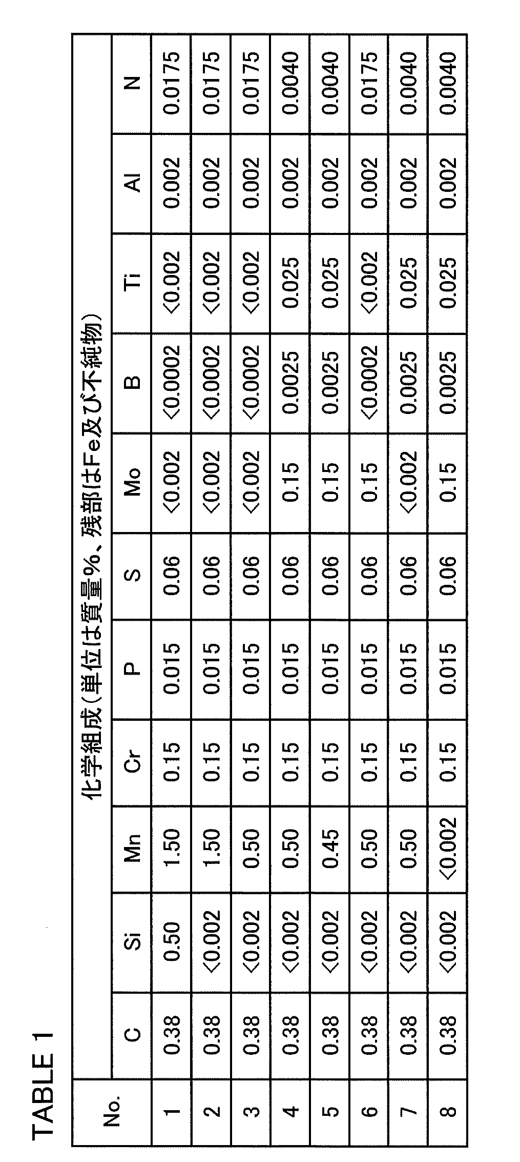
具体的には、素材を1250℃で1時間加熱した後、1100~850℃で熱間鍛造を実施し、鍛造終了後、室温まで放冷した。その後、1250℃で20分間加熱した後空冷する焼ならしを実施した後、機械加工(切削加工)によって外径を47.9mmにした。その後、高周波焼入れを実施して、表層部硬さHV650の焼入れ硬化層を形成した。
素材の焼入れ性を理想臨界直径Diによって評価した。具体的には、理想臨界直径Diが、従来鋼(Di≒1.98)の約9割である1.7以上であれば、クランクシャフトに必要な焼入れ性を有していると判断した。Diの計算にあたっては、0.002質量%未満のSi、0.002質量%未満のMn、0.002質量%未満のMoは、いずれも0%として扱った。表2に、Diの計算経過を示す。
実施形態で説明した方法にしたがって、焼入れ硬化層に固溶したSi、Mn、Cr、Mo、C、S、B、Ti、及びNの量(SiM、MnM、CrM、MoM、CM、SM、BM、TiM、及びNM)を測定した。Si含有量が0.002質量%未満のものはSiMが0%、Mn含有量が0.002質量%未満のものはMnMが0%、Mo含有量が0.002質量%未満のものはMoMが0%、B含有量が0.0002質量%未満のものはBMが0%、Ti含有量が0.002質量%未満のものはTiMが0%として扱った。一方、原子量の小さいNに関しては、0.0040質量%のものも0%とは扱わずにNMを求めた。
実施形態に説明した方法にしたがって、母材(焼入れ硬化層以外の部分)及び焼入れ硬化層の熱伝導率を測定した。
結果を表3に示す。表3のF1、及びF2の欄には、それぞれ式(1)、及び式(2)の左辺の値が記載されている。また、各欄の「-」は、該当する測定を実施していないことを意味する。

表3に示すように、No.4及び5の試験軸は、従来鋼(No.1)と同程度の理想臨界直径Diを有しつつ、45W/mK以上の高い熱伝導率を有していた。
No.2の試験軸は、焼入れ性は許容範囲であったものの、No.4及び5と比較して熱伝導率が劣っていた。これは、固溶Mnの量が多すぎたためと考えられる。
No.3の試験軸は、高い熱伝導率を有していたものの、焼入れ性が劣っていた。これは、No.6の試験軸がMo及びBを含有していなかったためと考えられる。
No.6の試験軸は、高い熱伝導率を有していたものの、焼入れ性が劣っていた。これは、No.6の試験軸がBを含有していなかったためと考えられる。
No.7の試験軸は、高い熱伝導率を有していたものの、焼入れ性が劣っていた。これは、No.7の試験軸がMoを含有していなかったためと考えられる。
No.8の試験軸は、高い熱伝導率を有していたものの、焼入れ性が劣っていた。これは、No.8の試験軸のMn含有量が低すぎたためと考えられる。
次に、No.2、4、及び5の試験軸を使用して、焼付き試験を実施した。焼付き試験に供する試験軸には、仕上加工として、断面曲線の算術平均高さPaが0.07~0.09μmになるように、研削及びラッピングを施した。試験軸の外径は、後述する焼付き試験に用いる軸受とのクリアランスが約0.090mmになるように調整した。
焼付き試験は、神鋼造機株式会社製クランクメタル耐摩耗焼付き性評価装置を用いて実施した。評価装置20の模式図を図7に示す。試験軸TPを複数の軸受21に挿入し、軸受21に給油しながら、モータ(不図示)によって試験軸TPを8000rpmで回転させた。軸受のメタルは、HV40~50のAl合金を使用した。潤滑油は0W-20、給油温度は140℃、油圧は0.8MPaとした。
この状態で、軸受21の一つを引き下げて試験軸TPに加わる面圧を段階的に増加させながら、焼付きが発生するまで運転した。図8に、試験軸TPに加えた面圧の時間変化を模式的に示す。同一面圧での保持時間は3分間、1ステップあたりの面圧増加幅は4.35MPa、面圧増加にかける時間は15秒間とした。試験軸TPの表面温度が280℃以上になるか、試験軸にかかるトルクが25Nm以上になったときに焼付きが発生したと判定した。各試験軸に対して3回の試験を実施し、その平均値を焼付面圧とした。
結果を前掲の表3及び図9に示す。図9は、試験軸の焼付き面圧を焼入れ硬化層の室温の熱伝導率との関係で示した図である。図9に示すように、熱伝導率の高いNo.4及び5の試験軸は、No.2の試験軸と比較して、優れた耐焼付き性を有することが確認された。
以上、本発明の一実施形態を説明したが、上述した実施形態は本発明を実施するための例示に過ぎない。よって、本発明は上述した実施形態に限定されることなく、その趣旨を逸脱しない範囲内で上述した実施形態を適宜変形して実施することが可能である。
Claims (4)
- 化学組成が、質量%で、
C :0.35~0.50%、
Si:0.55%以下、
Mn:0.01~0.55%、
Cr:0.10~0.50%、
P :0.03%以下、
S :0.10%以下、
Mo:0.10~0.30%、
B :0.0020~0.0050%、
Ti:0.020~0.10%、
N :0.020%以下、
Al:0.10%以下、
残部:Fe及び不純物であり、
焼入れ硬化層を表面に有し、
前記焼入れ硬化層へ固溶したSi、Mn、Cr、及びMoが、下記の式(1)を満たす、クランクシャフト。
1.960SiM+1.002MnM+1.059CrM+0.574MoM≦0.75 (1)
式(1)中のSiM、MnM、CrM、及びMoMにはそれぞれ、前記焼入れ硬化層へ固溶したSi、Mn、Cr、及びMoの量が質量%で代入される。 - 請求項1に記載のクランクシャフトであって、
前記焼入れ硬化層へ固溶したSi、Mn、Cr、Mo、C、S、B、Ti、及びNが、下記の式(2)を満たす、クランクシャフト。
1.960SiM+1.002MnM+1.059CrM+0.574MoM+4.585CM+1.717SM+5.094BM+1.150TiM+3.930NM≦2.00 (2)
式(2)中のSiM、MnM、CrM、MoM、CM、SM、BM、TiM、及びNMにはそれぞれ、前記焼入れ硬化層へ固溶したSi、Mn、Cr、Mo、C、S、B、Ti、及びNの量が質量%で代入される。 - 請求項1又は2に記載のクランクシャフトであって、
ASTM A255-67に準拠して前記化学組成から算出される理想臨界直径Diが1.7以上である、クランクシャフト。 - 請求項1~3のいずれか一項に記載のクランクシャフトであって、
前記焼入れ硬化層の室温の熱伝導率が45W/mK以上である、クランクシャフト。
Priority Applications (1)
| Application Number | Priority Date | Filing Date | Title |
|---|---|---|---|
| JP2021504120A JP7136320B2 (ja) | 2019-03-05 | 2020-03-03 | クランクシャフト |
Applications Claiming Priority (4)
| Application Number | Priority Date | Filing Date | Title |
|---|---|---|---|
| JP2019-039339 | 2019-03-05 | ||
| JP2019039339 | 2019-03-05 | ||
| JP2019165117 | 2019-09-11 | ||
| JP2019-165117 | 2019-09-11 |
Publications (1)
| Publication Number | Publication Date |
|---|---|
| WO2020179800A1 true WO2020179800A1 (ja) | 2020-09-10 |
Family
ID=72337484
Family Applications (1)
| Application Number | Title | Priority Date | Filing Date |
|---|---|---|---|
| PCT/JP2020/009004 Ceased WO2020179800A1 (ja) | 2019-03-05 | 2020-03-03 | クランクシャフト |
Country Status (2)
| Country | Link |
|---|---|
| JP (1) | JP7136320B2 (ja) |
| WO (1) | WO2020179800A1 (ja) |
Citations (4)
| Publication number | Priority date | Publication date | Assignee | Title |
|---|---|---|---|---|
| JP2005060723A (ja) * | 2003-08-08 | 2005-03-10 | Jfe Steel Kk | 曲げ疲労寿命に優れるクランクシャフトおよびその製造方法 |
| WO2012029395A1 (ja) * | 2010-08-31 | 2012-03-08 | 住友金属工業株式会社 | 高周波焼入れ用鋼及びそれを用いて製造されるクランクシャフト |
| JP2017061746A (ja) * | 2015-09-25 | 2017-03-30 | 新日鐵住金株式会社 | 鋼材及び摺動部品、並びに鋼材の製造方法 |
| JP2018150582A (ja) * | 2017-03-13 | 2018-09-27 | 新日鐵住金株式会社 | 鍛造部品 |
Family Cites Families (2)
| Publication number | Priority date | Publication date | Assignee | Title |
|---|---|---|---|---|
| JP4061003B2 (ja) * | 1999-12-24 | 2008-03-12 | 新日本製鐵株式会社 | 高周波焼入れ性と冷鍛性に優れた冷間鍛造用棒線材 |
| ES2292836T3 (es) * | 2002-10-18 | 2008-03-16 | Jfe Steel Corporation | Material de acero para estructura mecanica, extremadamente apropiado para laminacion, resistencia a fisuras por templado y propiedad de torsion y eje motor. |
-
2020
- 2020-03-03 JP JP2021504120A patent/JP7136320B2/ja active Active
- 2020-03-03 WO PCT/JP2020/009004 patent/WO2020179800A1/ja not_active Ceased
Patent Citations (4)
| Publication number | Priority date | Publication date | Assignee | Title |
|---|---|---|---|---|
| JP2005060723A (ja) * | 2003-08-08 | 2005-03-10 | Jfe Steel Kk | 曲げ疲労寿命に優れるクランクシャフトおよびその製造方法 |
| WO2012029395A1 (ja) * | 2010-08-31 | 2012-03-08 | 住友金属工業株式会社 | 高周波焼入れ用鋼及びそれを用いて製造されるクランクシャフト |
| JP2017061746A (ja) * | 2015-09-25 | 2017-03-30 | 新日鐵住金株式会社 | 鋼材及び摺動部品、並びに鋼材の製造方法 |
| JP2018150582A (ja) * | 2017-03-13 | 2018-09-27 | 新日鐵住金株式会社 | 鍛造部品 |
Also Published As
| Publication number | Publication date |
|---|---|
| JPWO2020179800A1 (ja) | 2021-11-25 |
| JP7136320B2 (ja) | 2022-09-13 |
Similar Documents
| Publication | Publication Date | Title |
|---|---|---|
| JP6098732B2 (ja) | 浸炭鋼部品の製造方法及び浸炭鋼部品 | |
| JP6610808B2 (ja) | 軟窒化用鋼および部品 | |
| JP7095116B2 (ja) | 浸炭窒化軸受部品の素材となる鋼材 | |
| JP2011153364A (ja) | クランクシャフトおよびその製造方法 | |
| WO2011158782A1 (ja) | 鍛造クランクシャフト | |
| JP5561436B2 (ja) | 熱間鍛造用圧延棒鋼又は線材 | |
| CN104508164A (zh) | 软氮化用钢和软氮化部件以及它们的制造方法 | |
| EP3190199B1 (en) | Non-tempered soft-nitrided component | |
| JP6098769B2 (ja) | 軟窒化用鋼および部品並びにこれらの製造方法 | |
| JP6561816B2 (ja) | クランクシャフト及びその製造方法 | |
| US20140182414A1 (en) | Steel for induction hardening and crankshaft manufactured by using the same | |
| JP2007131907A (ja) | 冷間加工性に優れる高周波焼入れ用鋼及びその製造方法 | |
| CN113646448B (zh) | 钢轴部件 | |
| JP7099553B2 (ja) | 鋼材及び部品 | |
| US20230304528A1 (en) | Crankshaft | |
| JP7368724B2 (ja) | 浸炭鋼部品用鋼材 | |
| JP7136320B2 (ja) | クランクシャフト | |
| US9956950B2 (en) | Non-thermal refined soft-nitrided component | |
| JP5969204B2 (ja) | 耐摩耗性と面疲労特性に優れた高周波焼入歯車およびその製造方法 | |
| JP3579558B2 (ja) | 耐焼割れ性に優れた軸受鋼 | |
| JP7139692B2 (ja) | 高周波焼入れ用鋼、高周波焼入れ部品の素形材及び高周波焼入れ部品 | |
| JP7343767B2 (ja) | クランクシャフト及びその製造方法 | |
| EP3406747A1 (en) | High strength forged steel and large forged component | |
| JP4723338B2 (ja) | 衝撃特性、曲げ疲労特性、面疲労特性に優れた高周波焼入歯車用鋼および歯車の製造方法 | |
| JPWO2020090816A1 (ja) | 窒化部品粗形材、および窒化部品 |
Legal Events
| Date | Code | Title | Description |
|---|---|---|---|
| 121 | Ep: the epo has been informed by wipo that ep was designated in this application |
Ref document number: 20765724 Country of ref document: EP Kind code of ref document: A1 |
|
| ENP | Entry into the national phase |
Ref document number: 2021504120 Country of ref document: JP Kind code of ref document: A |
|
| NENP | Non-entry into the national phase |
Ref country code: DE |
|
| 122 | Ep: pct application non-entry in european phase |
Ref document number: 20765724 Country of ref document: EP Kind code of ref document: A1 |