WO2020179626A1 - アシストグリップ - Google Patents
アシストグリップ Download PDFInfo
- Publication number
- WO2020179626A1 WO2020179626A1 PCT/JP2020/008072 JP2020008072W WO2020179626A1 WO 2020179626 A1 WO2020179626 A1 WO 2020179626A1 JP 2020008072 W JP2020008072 W JP 2020008072W WO 2020179626 A1 WO2020179626 A1 WO 2020179626A1
- Authority
- WO
- WIPO (PCT)
- Prior art keywords
- shaft
- grip
- hinge member
- assist grip
- protruding
- Prior art date
- Legal status (The legal status is an assumption and is not a legal conclusion. Google has not performed a legal analysis and makes no representation as to the accuracy of the status listed.)
- Ceased
Links
Images




Classifications
-
- B—PERFORMING OPERATIONS; TRANSPORTING
- B60—VEHICLES IN GENERAL
- B60N—SEATS SPECIALLY ADAPTED FOR VEHICLES; VEHICLE PASSENGER ACCOMMODATION NOT OTHERWISE PROVIDED FOR
- B60N3/00—Arrangements or adaptations of other passenger fittings, not otherwise provided for
- B60N3/02—Arrangements or adaptations of other passenger fittings, not otherwise provided for of hand grips or straps
Definitions
- the present invention relates to an assist grip provided in a vehicle such as an automobile and gripped by an occupant.
- Assistance grips have conventionally been provided inside the vehicle as handrails that the occupant grasps to support his/her body when getting on/off or running.
- a handle body is rotatably supported by a hinge.
- the hinge has a pair of round boss portions that serve as a rotation axis of the handle body, and the handle body has a pair of groove portions into which the respective round boss portions are inserted.
- the grip body is rotatably supported by a hinge member as in the assist grip disclosed in Document 1.
- the rotary shaft has a pin member. One end of this pin member is pushed by a jig, the other end is attached to the bearing hole, and then the stopper is attached to the one end to restrict the slide.
- the circular boss on the rotating shaft is short with respect to the depth of the groove.
- the degree of insertion of the part is small. Therefore, for example, the round boss portion may come off from the groove portion due to the impact when the side curtain airbag or the like is deployed.
- the present invention has been proposed in view of such circumstances. That is, it is an object of the present invention to provide an assist grip that is easy to assemble and is robust.
- an assist grip has a grip body provided inside a vehicle and a protruding shaft portion that constitutes a rotation shaft of the grip body, and is interposed between a panel inside the vehicle and the grip body.
- a hinge member that rotatably supports the grip body, and a shaft member that is disposed coaxially with the projecting shaft portion and that is interposed between the grip body and the hinge member and that constitutes a rotation shaft of the grip body.
- a stopper portion that locks on the outer periphery of the shaft member and restricts the shaft member from sliding in the rotation axis direction.
- the shaft member has a locked portion with which the stopper portion is locked, the locked portion is a shaft main body portion inserted into the hinge member, and the shaft main body. It is characterized in that it is formed by a step with a shaft enlarged diameter portion having a diameter larger than the diameter of the portion.
- the hinge member has a pair of shaft support holes formed coaxially with the protruding shaft portion on a rotation shaft, and the shaft member has both the shaft support holes and the protrusion. It is characterized in that it is inserted into the shaft portion.
- the grip body has a pair of shaft grooves that support a rotating shaft, and when the shaft member is abutted against one of the shaft grooves and the stopper portion is attached, The stopper portion slides the hinge member in the rotation axis direction with respect to the shaft member, whereby the protruding shaft portion is abutted against the other shaft groove.
- the assist grip according to the present invention is characterized in that the stopper portion is formed on a cap body attached to the hinge member.
- An assist grip has a grip body provided inside a vehicle and a protruding shaft portion that constitutes a rotating shaft of the grip body, and rotatably supports the grip body by interposing a panel inside the vehicle and the grip body.
- Hinge member a shaft member that is interposed between the grip body and the hinge member and is disposed coaxially with the projecting shaft portion, and that constitutes a rotating shaft of the grip body, and the shaft member that is locked to the outer periphery of the shaft member.
- the shaft member has a locked portion with which the stopper portion is locked, and the locked portion has a shaft body portion inserted into the hinge member and a diameter of the shaft body portion. It is formed by a step with a shaft expansion portion having a larger diameter. That is, the stopper portion is caught by the step between the shaft main body portion and the shaft expanded diameter portion, so that the shaft member is restricted from sliding toward the shaft main body portion. Therefore, the structure is simple and the assembling work is easy.
- the hinge member has a pair of shaft support holes formed coaxially with the protruding shaft portion on the rotating shaft, and the shaft member is inserted into both the shaft supporting holes and the protruding shaft portion. Has been done. That is, since the shaft member is inserted over the shaft support hole and the protruding shaft portion of the hinge member, the rotating shaft is robust.
- the grip body has a pair of shaft grooves for supporting the rotating shaft, and when the shaft member is abutted against one shaft groove and the stopper part is attached, the stopper part is hinged.
- the protruding shaft portion is abutted against the other shaft groove. That is, before the stopper portion is attached, the shaft member is abutted against one of the shaft grooves, and the stopper portion is attached so that only the hinge member slides with respect to the shaft member whose sliding is restricted, and the other.
- the protruding shaft portion of the hinge member is abutted against the shaft groove of. Therefore, the assembly work is easy without the need for jigs and the like. Moreover, since it has a shaft member, it is robust.
- the stopper portion is formed on a cap body attached to the hinge member. Therefore, the assembly work is easy.
- FIG. 1 is an external perspective view of an assist grip according to an embodiment of the present invention.
- FIG. 2 is an exploded perspective view of the assist grip according to the embodiment of the present invention.
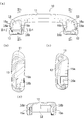
- FIG. 3A is a back view of the grip body of the assist grip according to the embodiment of the present invention as viewed from the back side.
- FIG. 3B is a one-sided cross-sectional view of IIIb-IIIb viewed from one side in FIG. 3A.
- FIG. 3C is a one-sided cross-sectional view of IIIc-IIIc viewed from one side in FIG. 3A.
- FIG. 3D is a cross-sectional view on the upper side of IIId-IIId viewed from the upper side in FIG. 3A.
- FIG. 4A is a back view of the hinge member in the assist grip according to the embodiment of the present invention.
- FIG. 4B is a bottom view of the hinge member as viewed from below.
- FIG.4(c) is the other side view which looked at the hinge member from the other side.
- FIG. 4D is a rear perspective view of the hinge member.
- FIG. 4E is a front perspective view of the hinge member viewed from the front side.
- FIG. 5A is a back view of the cap body in the assist grip according to the embodiment of the present invention.
- FIG. 5B is one side view of the cap body.
- FIG. 5C is a bottom view of the cap body.
- FIG. 5D is a perspective view of the cap body.
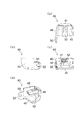
- FIG. 6A is a bottom view of the assist grip in the process of assembling the assist grip according to the embodiment of the present invention.
- FIG. 6B is a VI-VI front side cross section viewed from the front side in FIG. 6A, and is an explanatory view of a hinge member mounting process.
- FIG. 6 (c) is a front cross section of VI-VI in FIG. 6 (a), and is an explanatory view of an attachment process of the stopper portion.
- FIG. 6D is a front cross section of VI-VI in FIG. 6A, which is a completed assembly drawing.
- FIG. 1 shows the appearance of the assist grip 1
- FIG. 2 shows the disassembled assist grip 1.
- the assist grip 1 is provided in an automobile (not shown) and is gripped by an occupant.
- the assist grip 1 is attached to, for example, a pillar or a roof panel of an automobile, and when pulled by an occupant, the assist grip 1 rotates about a lower portion as a rotation axis and the upper portion extends into the vehicle.
- the side where the assist grip 1 is attached to the vehicle panel is the back side
- the side exposed to the occupant side of the vehicle is the front side
- the right side is the other side
- the rotating shaft side is the side. Is downward and the opposite side is upward (see FIGS. 1 and 2).
- the assist grip 1 constitutes a grip main body 10 to be gripped by an occupant, a rotary shaft of the grip main body 10, and is interposed between a panel inside the vehicle and the grip main body 10 to grip the grip.
- a pair of hinge members 20 that rotatably support the main body 10, a pair of shaft members 5 that intervene between the grip body 10 and the hinge member 20 to form a rotation axis of the grip body 10, and a pair that is attached to the hinge member 20.
- the cap body 40 is formed with a stopper portion 50 that is locked to the outer periphery of the shaft member 5 and restricts the shaft member 5 from sliding in the rotation axis X direction.
- the torsion spring 3 is attached to one side of the grip body 10 together with each member, and the damper 4 is attached to the other side of the grip body 10 together with each member. Except for the torsion spring 3 and the damper 4, each part is Since they are almost the same, each part on one side will be described below, and the description on the other side will be omitted.
- FIGS. 4(a)(b)(c)(d)(e) shows the hinge member 20.
- 5(a)(b)(c)(d) shows the cap body 40.
- the grip body 10 includes a grip portion 11 having a long rod shape, and projecting downward at both ends of the grip portion 11. And the formed overhang portion 12.
- the overhanging portion 12 is formed with a housing portion 13 that is recessed from the back side to the front side.
- the accommodating portion 13 has a pair of shaft grooves 14a and 14a and b on the inside.
- the shaft grooves 14a and 14b are located on the rotation axis X and are formed in the facing inner wall portions 15a and 15b of the housing portion 13, respectively.
- the shaft grooves 14a and 14b are "L"-shaped, which is directed from the back side to the front side in the inner wall portions 15a and 15b, abuts, and faces downward.
- the hinge member 20 includes a board portion 21 having a substantially rectangular flat plate shape, and a front side of the board portion 21. It has a fixed protrusion 22 protruding toward the back side of the substrate portion 21 and a shaft base portion 25 protruding toward the back side of the substrate portion 21.
- the fixed protrusion 22 is formed on the upper side of the front side of the substrate 21, and the opening 23 that is a hole is formed on the lower side of the front of the substrate 21.
- Clip holes 33a and 33b are formed in the substrate portion 21 above and below the fixed protrusion 22, respectively.
- the clip holes 33a and 33b penetrate the front and back.
- a part of the substrate portion 21 forming the edge of the opening 23 is a frame portion 24.
- the shaft base portion 25 includes a shaft base body portion 26 connected to the center on the back side of the base plate portion 21, and a shaft base end portion 28 protruding from the shaft base body portion 26 toward the back side and downward and facing the opening portion 23. have.
- the shaft basic body portion 26 is formed with fitting holes 27 penetrating vertically.
- the shaft base end portion 28 has a pair of support wall portions 29a and 29b facing each other.
- the support wall portions 29a and 29b are respectively arranged on one side and the other side on the back side of the opening portion 23, and the support wall portion 29b on the other side has a protruding shaft portion 30.
- the protruding shaft portion 30 projects from the outside of the support wall portion 29b to the other side.
- the support wall portions 29a and 29b have a pair of shaft support holes 32a and 32b.
- the shaft support holes 32a and 32b are formed so as to penetrate the protruding shaft portion 30 on the rotation axis X and to be coaxial with the protruding shaft portion 30.
- a spring accommodating portion 31 is formed between the support wall portions 29a and 29b.
- the cap body 40 includes a flat plate-shaped upper surface portion 41 on the upper side, and the upper surface portion 41 facing the front side.
- a flat plate-shaped surface portion 42 connected to each other, a side surface portion 43 connected to one side of the upper surface portion 41 and the surface portion 42, a stopper portion 50 protruding downward from a lower end of the side surface portion 43, and an upper surface portion. It has a fitting protrusion 52 that protrudes downward on the lower surface of the 41.
- a notch groove 51 is formed at the lower end of the stopper portion 50. The notch groove 51 has a size in which the shaft body 6 of the shaft member 5, which will be described later, is sandwiched.
- the shaft member 5 is rod-shaped, and has a long shaft body 6 and a shaft formed at one end of the shaft body 6 and having a diameter larger than the diameter of the shaft body 6. It has an enlarged diameter portion 7.
- the shaft member 5 has a locked portion 8 formed on the outer periphery by a step due to a difference in diameter between the shaft main body portion 6 and the shaft expanded diameter portion 7.
- the shaft member 5 is made of metal, for example.
- the torsion spring 3 is housed in the spring housing portion 31 of the hinge member 20.
- the shaft body 6 of the shaft member 5 is passed through the shaft support hole 32a (see FIG. 4D) of the hinge member 20 from one side and is also passed through the torsion spring 3.
- the tip end of 6 is passed through the protruding shaft portion 30 of the hinge member 20 (the shaft support hole 32b, see FIG. 4D) and is aligned coaxially.
- the clip 2 is inserted into the clip holes 33a and 33b of the hinge member 20 (hereinafter, this state is referred to as "primary assembly").
- the primary assembly is housed in the housing portion 13 of the assist grip 1. More specifically, the shaft expanded diameter portion 7 of the shaft member 5 is attached to the one shaft groove 14a of the housing portion 13, and the protruding shaft portion 30 of the hinge member 20 together with the shaft body portion 6 of the shaft member 5 is housed. It is attached to the other axial groove 14b of 13 (see FIG. 6B). That is, the shaft member 5 and the protruding shaft portion 30 constitute a rotary shaft, and the rotary shaft is supported by the shaft grooves 14a and 14b (see FIG. 6C).
- the cap body 40 is attached to the hinge member 20 in a state in which the shaft expanded portion 7 is abutted against the inner wall portion 15a on one side of the shaft groove 14a. More specifically, the fitting protrusion 52 of the cap body 40 is passed through the fitting hole 27 of the hinge member 20 from above (see FIG. 2 ), and at the same time, the stopper portion 50 of the cap body 40 is inserted into the shaft member 5. Locks to the locked portion 8 of. That is, the locked portion 8 is sandwiched in the notch groove 51 of the stopper portion 50. At this time, as shown in FIG.
- the stopper portion 50 causes the hinge member 20 to move relative to the shaft member 5 with respect to the rotation axis X.
- the protruding shaft portion 30 By sliding the protruding shaft portion 30 to the other side, the protruding shaft portion 30 is abutted against the inner wall portion 15b on the other side of the shaft groove 14b of the hinge member 20.
- the shaft member 5 constitutes a rotating shaft from the shaft groove 14a to the protruding shaft portion 30.
- the frame portion 24 of the hinge member 20 reaches the lower end of the projecting portion 12 of the grip body 10 and covers the back side of the projecting portion 12 (see FIG. 1 ).
- Assist Grip 1 is assembled.
- the fixed protrusion 22 of the hinge member 20 is inserted into a predetermined position on the panel of the automobile.
- the frame portion 24 of the hinge member 20 faces the panel.
- the assist grip 1 has the shaft member 5 which is interposed between the grip body 10 and the hinge member 20 and constitutes the rotating shaft of the grip body 10, and the cap body 40 which is attached to the hinge member 20. ..
- the shaft member 5 has a locked portion 8 formed on the outer periphery due to a step due to a difference in diameter between the shaft main body portion 6 and the shaft expanded diameter portion 7, while the cap body 40 is locked to the locked portion 8. It has a stopper portion 50 that restricts the shaft member 5 from sliding in the rotation axis X direction.
- the stopper portion 50 holds the hinge member 20 and the shaft member 5 in a state where the shaft expanded portion 7 is stopped by the stopper portion 50.
- the protruding shaft portion 30 is abutted against the inner wall portion 15b on the other side in the shaft groove 14b of the hinge member 20 (see FIG. 6D). Therefore, a jig or the like is not required, and the assembly work is easy. Further, since it has the shaft member 5, it is robust.
- the shaft expanded diameter portion 7 is attached to the one shaft groove 14 a in the housing portion 13, and the protruding shaft portion 30 of the hinge member 20 together with the shaft main body portion 6 of the shaft member 5 are housed in the housing portion 13. It is attached to the other axial groove 14b in (see FIGS. 6(b) and 6(c)). That is, the shaft member 5 extends from the shaft groove 14a to the protruding shaft portion 30, and constitutes a rotating shaft together with the protruding shaft portion 30. Therefore, the axis of rotation is robust. Further, since the shaft member 5 is made of metal, the rotating shaft is more robust.
- the stopper portion 50 is formed on the cap body 40 attached to the hinge member 20 (see FIGS. 5A, 5B, 5C and 5D). With this configuration, by attaching the cap body 40 to the hinge member 20, the stopper portion 50 is locked to the locked portion 8 of the shaft member 5, and the hinge member 20 is rotated relative to the shaft member 5 with respect to the rotation axis. Slide to the other side of X. Therefore, the assembly work is easy.
- the frame portion 24 of the hinge member 20 reaches the lower end of the protruding portion 12 of the grip body 10 and covers the back side of the protruding portion 12 (see FIG. 1).
- the load applied to the hinge member 20 from the panel acts on the frame portion 24, and the load on the rotating shaft of the grip body 10 is suppressed. Therefore, it is robust.
- the locked portion may be, for example, an annular groove or an annular flange.
- the cap body and the stopper portion may be separate members.
Landscapes
- Engineering & Computer Science (AREA)
- Transportation (AREA)
- Mechanical Engineering (AREA)
- Passenger Equipment (AREA)
Abstract
組立作業が容易で、堅牢なアシストグリップを提供する。グリップ本体10と、このグリップ本体10の回転軸を構成すると共に車内のパネルとグリップ本体10とに介在してグリップ本体10を回転可能に支持するヒンジ部材20と、グリップ本体10とヒンジ部材20とに介在してグリップ本体10の回転軸を構成する軸部材5と、ヒンジ部材20に取り付けられるキャップ体40とを有し、キャップ体40は、被係止部8に係止して軸部材5が回転軸線X方向にスライドすることを規制するストッパ部50を有している。
Description
本発明は、自動車などの車内に備えられて乗員が把持するアシストグリップに関するものである。
従来、乗降時または走行時に乗員が自身の体を支えるために掴む手摺として、車内にアシストグリップが備えられている。例えば、下記特許文献1に記載されたアシストグリップ(以下、「文献1開示アシストグリップ」と記す。)は、ヒンジによってハンドル本体が回転可能に支持されている。ヒンジは、ハンドル本体の回転軸となる一対の丸ボス部を有し、ハンドル本体は、それぞれの丸ボス部が挿入された一対の溝部を有している。一方、下記特許文献2に記載されたアシストグリップ(以下、「文献2開示アシストグリップ」と記す。)は、文献1開示アシストグリップと同様に、ヒンジ部材によってグリップ本体が回転可能に支持されているが、回転軸にピン部材を有している点において、文献1開示アシストグリップと異なる。このピン部材は、冶具によって一端部が押されることで、他端部が軸受孔に取り付けられた後、一端部側にストッパ部が取り付けられることでスライドが規制される。
文献1開示アシストグリップは、ヒンジがハンドル本体に取り付けられる際、ヒンジが回転軸上をスライドすることから、回転軸上において、溝部の深さに対して丸ボス部が短いため、溝部に対する丸ボス部の挿入の度合いが少ない。そのため、例えばサイドカーテンエアバッグなどが展開する際の衝撃によって丸ボス部が溝部から外れる場合がある。
文献2開示アシストグリップは、冶具によるピン部材の取付作業を経ることから、作業工数が嵩む。
本発明は、この様な実情に鑑みて提案されたものである。すなわち、組立作業が容易であり、かつ、堅牢なアシストグリップの提供を目的とする。
上記目的を達成するために、本発明に係るアシストグリップは、車内に備えられるグリップ本体と、前記グリップ本体の回転軸を構成する突軸部を有し、車内のパネルと前記グリップ本体とに介在して前記グリップ本体を回転可能に支持するヒンジ部材と、前記グリップ本体と前記ヒンジ部材とに介在して前記突軸部と同軸上に配置され、前記グリップ本体の回転軸を構成する軸部材と、前記軸部材の外周に係止して、前記軸部材が回転軸方向にスライドすることを規制するストッパ部と、を有する、ことを特徴とする。
本発明に係るアシストグリップは、前記軸部材が、前記ストッパ部が係止する被係止部を有し、前記被係止部が、前記ヒンジ部材に挿入された軸本体部と、この軸本体部の直径よりも大きい直径を有する軸拡径部との段差によって形成された、ことを特徴とする。
本発明に係るアシストグリップは、前記ヒンジ部材が、回転軸上において前記突軸部と同軸上に形成された一対の軸支持孔を有し、前記軸部材が、両前記軸支持孔と前記突軸部とに挿入された、ことを特徴とする。
本発明に係るアシストグリップは、前記グリップ本体が、回転軸を支持する一対の軸溝を有し、一方の前記軸溝に、前記軸部材が突き当てられ、前記ストッパ部が取り付けられる際、前記ストッパ部が、前記ヒンジ部材を、前記軸部材に対して回転軸方向にスライドさせることで、前記突軸部が、他方の前記軸溝に突き当てられる、ことを特徴とする。
本発明に係るアシストグリップは、前記ストッパ部が、前記ヒンジ部材に取り付けられるキャップ体に形成された、ことを特徴とする。
本発明に係るアシストグリップは、車内に備えられるグリップ本体と、このグリップ本体の回転軸を構成する突軸部を有し、車内のパネルとグリップ本体とに介在してグリップ本体を回転可能に支持するヒンジ部材と、グリップ本体とヒンジ部材とに介在して突軸部と同軸上に配置され、グリップ本体の回転軸を構成する軸部材と、この軸部材の外周に係止して、軸部材が回転軸方向にスライドすることを規制するストッパ部とを有している。すなわち、ストッパ部が軸部材の外周に係止することで、軸部材がスライドすることが規制される。したがって、冶具などを要さず、組立作業が容易である。また、軸部材を有するため、堅牢である。
本発明に係るアシストグリップは、軸部材が、ストッパ部が係止する被係止部を有し、この被係止部が、ヒンジ部材に挿入された軸本体部と、この軸本体部の直径よりも大きい直径を有する軸拡径部との段差によって形成されている。すなわち、ストッパ部が、軸本体部と軸拡径部との段差に引っ掛かることで、軸部材が、軸本体部側にスライドすることが規制される。したがって、構成が簡便であり、組立作業が容易である。
本発明に係るアシストグリップは、ヒンジ部材が、回転軸上において突軸部と同軸上に形成された一対の軸支持孔を有し、軸部材が、両軸支持孔と突軸部とに挿入されている。すなわち、ヒンジ部材の軸支持孔および突軸部に渡って軸部材が挿入されているため、回転軸が堅牢である。
本発明に係るアシストグリップは、グリップ本体が、回転軸を支持する一対の軸溝を有し、一方の軸溝に、軸部材が突き当てられ、ストッパ部が取り付けられる際、ストッパ部が、ヒンジ部材を、軸部材に対して回転軸方向にスライドさせることで、突軸部が、他方の軸溝に突き当てられる。すなわち、ストッパ部が取り付けられる前では、一方の軸溝に軸部材が突き当てられ、ストッパ部が取り付けられることで、スライドすることが規制された軸部材に対してヒンジ部材のみがスライドし、他方の軸溝にヒンジ部材の突軸部が突き当てられる。したがって、冶具などを要さず、組立作業が容易である。また、軸部材を有するため、堅牢である。
本発明に係るアシストグリップは、ストッパ部が、ヒンジ部材に取り付けられるキャップ体に形成されている。したがって、組立作業が容易である。
以下に、本発明の実施形態に係るアシストグリップを図面に基づいて説明する。図1は、アシストグリップ1の外観が示され、図2は、分解されたアシストグリップ1が示されている。
アシストグリップ1は、自動車(図示省略。)内に備えられ、乗員が把持するものである。アシストグリップ1は、例えば、自動車のピラーやルーフパネルに取り付けられ、乗員により引っ張られることで、下方を回転軸として回転すると共に上方が車内に張り出る。なお、以下の説明では、アシストグリップ1が自動車のパネルに取り付けられる側を裏側、自動車の乗員側に露出する側を表側、裏側から視して左方を一方、右方を他方、回転軸側を下方、反対側を上方とする(図1及び図2参照。)。
図1及び図2に示されているとおり、アシストグリップ1は、乗員が把持するグリップ本体10と、このグリップ本体10の回転軸を構成すると共に車内のパネルとグリップ本体10とに介在してグリップ本体10を回転可能に支持する一対のヒンジ部材20と、グリップ本体10とヒンジ部材20とに介在してグリップ本体10の回転軸を構成する一対の軸部材5と、ヒンジ部材20に取り付けられる一対のキャップ体40と、ヒンジ部材20に取り付けられる一対のクリップ2と、グリップ本体10を元の位置に戻すためのトーションバネ3と、グリップ本体10の動きを制動するダンパー4とを有している。
ここで、キャップ体40は、軸部材5の外周に係止して軸部材5が回転軸線X方向にスライドすることを規制するストッパ部50が形成されている。なお、グリップ本体10の一方側に、各部材と共にトーションバネ3が取り付けられ、グリップ本体10の他方側に、各部材と共にダンパー4が取り付けられるところ、トーションバネ3及びダンパー4を除けば、各部はほぼ同様であるため、以下では、一方側の各部において説明し、他方側の説明を省略する。
図3(a)(b)(c)(d)は、グリップ本体10が示され、図4(a)(b)(c)(d)(e)は、ヒンジ部材20が示され、図5(a)(b)(c)(d)は、キャップ体40が示されている。
図2及び図3(a)(b)(c)(d)に示されているとおり、グリップ本体10は、長手の棒状である把持部11と、この把持部11の両端において下方に張り出して形成された張り出し部12とを有している。張り出し部12は、裏側から表側に向けて陥没した収容部13が形成されている。収容部13は、内側に一対の軸溝14a,bを有している。軸溝14a,bは、回転軸線X上にあり、収容部13における対面した内壁部15a,bにそれぞれ形成されている。軸溝14a,bは、内壁部15a,bにおいて裏側から表側に向かい、突き当たると共に下方に向かった「L」字状である。
図2及び図4(a)(b)(c)(d)(e)に示されているとおり、ヒンジ部材20は、ほぼ四角形の平板状である基板部21と、この基板部21の表側に向け突出した固定突部22と、基板部21の裏側に向けて突出した軸基部25とを有している。固定突部22は、基板部21の表側における上方側に形成され、基板部21の表側における下方側には、孔である開口部23が形成されている。基板部21は、固定突部22の上方及び下方のそれぞれに、クリップ孔33a,bが形成されている。クリップ孔33a,bは、表裏に貫通している。開口部23の縁を形成する基板部21の一部は、枠部24である。軸基部25は、基板部21の裏側における中央に連接された軸基本体部26と、この軸基本体部26から裏側かつ下方に向けて突出して開口部23と対峙した軸基端部28とを有している。軸基本体部26は、上下に貫通した嵌合孔27が形成されている。軸基端部28は、互いに対面した一対の支持壁部29a,bを有している。支持壁部29a,bは、開口部23の裏側において、一方側及び他方側にそれぞれ配置され、他方側の支持壁部29bに、突軸部30を有している。突軸部30は、支持壁部29bの外側から他方側に突出している。支持壁部29a,bは、一対の軸支持孔32a,bを有している。軸支持孔32a,bは、回転軸線X上において突軸部30を貫通し、突軸部30と同軸上に形成されている。支持壁部29a,bの間は、バネ収容部31が形成されている。
図2及び図5(a)(b)(c)(d)に示されているとおり、キャップ体40は、上方側にある平板状の上面部41と、この上面部41から表側に向けて連接された平板状の表面部42と、上面部41及び表面部42の一方側に連接された側面部43と、この側面部43の下端から下方に向けて突出したストッパ部50と、上面部41の下面において下方に向けて突出した嵌合突部52とを有している。ストッパ部50は、下端に切欠き溝51が形成されている。切欠き溝51は、後述する軸部材5の軸本体部6が挟まる大きさである。
図2に示されているとおり、軸部材5は棒状であり、長手の軸本体部6と、この軸本体部6の一方端に形成されて軸本体部6の直径よりも大きい直径を有する軸拡径部7とを有している。軸部材5は、軸本体部6と軸拡径部7との直径の差異による段差によって、外周に被係止部8が形成されている。軸部材5は、例えば金属製である。
以上のとおり構成された各部が組み立てられ、アシストグリップ1が完成する(図1参照。)。ここで、アシストグリップ1の組み立て手順を説明する。図6(a)(b)(c)(d)は、アシストグリップ1の組み立て過程が示されている。
図2において、トーションバネ3がヒンジ部材20のバネ収容部31に収容される。この状態で、軸部材5の軸本体部6が、ヒンジ部材20の軸支持孔32a(図4(d)参照。)に、一方側から通されると共にトーションバネ3に通され、軸本体部6の先端が、ヒンジ部材20の突軸部30(軸支持孔32b、図4(d)参照。)に通されて同軸上に揃えられる。クリップ2が、ヒンジ部材20のクリップ孔33a,bに挿入される(以下、この状態を「一次組立体」と記す。)。
図6(a)(b)(c)(d)に示されているとおり、一次組立体が、アシストグリップ1の収容部13に収容される。詳説すれば、軸部材5の軸拡径部7が、収容部13における一方の軸溝14aに取り付けられ、ヒンジ部材20の突軸部30が、軸部材5の軸本体部6と共に、収容部13における他方の軸溝14bに取り付けられる(図6(b)参照。)。すなわち、軸部材5と突軸部30とで回転軸が構成され、この回転軸が、軸溝14a,bにおいて支持されている(図6(c)参照。)。
軸拡径部7が、軸溝14aにおける一方側の内壁部15aに突き当てられた状態において、キャップ体40がヒンジ部材20に取り付けられる。詳説すれば、キャップ体40の嵌合突部52が、ヒンジ部材20の嵌合孔27に、上方から通され(図2参照。)、同時に、キャップ体40のストッパ部50が、軸部材5の被係止部8に係止する。すなわち、被係止部8が、ストッパ部50の切欠き溝51に挟まる。その際、図6(d)に示されているとおり、軸拡径部7がストッパ部50によって停められた状態で、ストッパ部50は、ヒンジ部材20を、軸部材5に対して回転軸線Xにおける他方側にスライドさせることで、突軸部30が、ヒンジ部材20の軸溝14bにおける他方側の内壁部15bに突き当てられる。軸部材5は、軸溝14aから突軸部30に渡って回転軸を構成している。ヒンジ部材20の枠部24は、グリップ本体10における張り出し部12の下端に至り、張り出し部12の裏側を覆っている(図1参照。)。
以上のとおり、アシストグリップ1が組み立てられる。アシストグリップ1は、ヒンジ部材20の固定突部22が、自動車におけるパネルの所定箇所に差し込まれる。ヒンジ部材20の枠部24は、パネルと対面する。
次に、アシストグリップ1の効果を説明する。
上記したとおり、アシストグリップ1は、グリップ本体10とヒンジ部材20とに介在してグリップ本体10の回転軸を構成する軸部材5と、ヒンジ部材20に取り付けられるキャップ体40とを有している。軸部材5は、軸本体部6と軸拡径部7との直径の差異による段差によって、外周に被係止部8が形成され、一方、キャップ体40は、被係止部8に係止して軸部材5が回転軸線X方向にスライドすることを規制するストッパ部50を有している。すなわち、被係止部8が、ストッパ部50の切欠き溝51に挟まる際、軸拡径部7がストッパ部50によって停められた状態で、ストッパ部50は、ヒンジ部材20を、軸部材5に対して回転軸線Xにおける他方側にスライドさせることで、突軸部30が、ヒンジ部材20の軸溝14bにおける他方側の内壁部15bに突き当てられる(図6(d)参照。)。したがって、冶具などを要さず、組立作業が容易である。また、軸部材5を有するため、堅牢である。
特に、軸部材5は、軸拡径部7が、収容部13における一方の軸溝14aに取り付けられ、ヒンジ部材20の突軸部30が、軸部材5の軸本体部6と共に、収容部13における他方の軸溝14bに取り付けられる(図6(b)(c)参照。)。すなわち、軸部材5は、軸溝14aから突軸部30に渡り、突軸部30と共に回転軸を構成している。したがって、回転軸が堅牢である。さらに、軸部材5が金属であるため、回転軸は、より堅牢である。
アシストグリップ1は、ストッパ部50が、ヒンジ部材20に取り付けられるキャップ体40に形成されている(図5(a)(b)(c)(d)参照。)。この構成により、キャップ体40がヒンジ部材20に取り付けられることで、ストッパ部50が、軸部材5の被係止部8に係止すると共に、ヒンジ部材20を、軸部材5に対して回転軸線Xにおける他方側にスライドさせる。したがって、組立作業が容易である。
アシストグリップ1は、ヒンジ部材20の枠部24が、グリップ本体10における張り出し部12の下端に至り、張り出し部12の裏側を覆っている(図1参照。)。例えば、エアバッグが展開してパネルが外れる際、パネルからヒンジ部材20に加えられる負荷が、枠部24に作用することで、グリップ本体10の回転軸に対する負荷が抑えられる。したがって、堅牢である。
なお、他の実施形態として、被係止部は、例えば、環状の溝又は環状のフランジなどであってもよい。また、他の実施形態として、キャップ体とストッパ部とが別々の部材であってもよい。
以上、本発明の実施形態を詳述したが、本発明は上記した実施形態に限定されるものではない。そして本発明は、特許請求の範囲に記載された事項を逸脱することがなければ、種々の設計変更を行うことが可能である。
1 アシストグリップ
2 クリップ
3 トーションバネ
4 ダンパー
5 軸部材
6 軸本体部
7 軸拡径部
8 被係止部
10 グリップ本体
11 把持部
12 張り出し部
13 収容部
14a,b 軸溝
15a,b 内壁部
20 ヒンジ部材
21 基板部
22 固定突部
23 開口部
24 枠部
25 軸基部
26 軸基本体部
27 嵌合孔
28 軸基端部
29a,b 支持壁部
30 突軸部
31 バネ収容部
32a,b 軸支持孔
33a,b クリップ孔
40 キャップ体
41 上面部
42 表面部
43 側面部
50 ストッパ部
51 切欠き溝
52 嵌合突部
X 回転軸線
2 クリップ
3 トーションバネ
4 ダンパー
5 軸部材
6 軸本体部
7 軸拡径部
8 被係止部
10 グリップ本体
11 把持部
12 張り出し部
13 収容部
14a,b 軸溝
15a,b 内壁部
20 ヒンジ部材
21 基板部
22 固定突部
23 開口部
24 枠部
25 軸基部
26 軸基本体部
27 嵌合孔
28 軸基端部
29a,b 支持壁部
30 突軸部
31 バネ収容部
32a,b 軸支持孔
33a,b クリップ孔
40 キャップ体
41 上面部
42 表面部
43 側面部
50 ストッパ部
51 切欠き溝
52 嵌合突部
X 回転軸線
Claims (5)
- 車内に備えられるグリップ本体と、
前記グリップ本体の回転軸を構成する突軸部を有し、車内のパネルと前記グリップ本体とに介在して前記グリップ本体を回転可能に支持するヒンジ部材と、
前記グリップ本体と前記ヒンジ部材とに介在して前記突軸部と同軸上に配置され、前記グリップ本体の回転軸を構成する軸部材と、
前記軸部材の外周に係止して、前記軸部材が回転軸方向にスライドすることを規制するストッパ部と、を有する、
ことを特徴とするアシストグリップ。 - 前記軸部材が、前記ストッパ部が係止する被係止部を有し、
前記被係止部が、前記ヒンジ部材に挿入された軸本体部と、この軸本体部の直径よりも大きい直径を有する軸拡径部との段差によって形成された、
ことを特徴とする請求項1に記載されたアシストグリップ。 - 前記ヒンジ部材が、回転軸上において前記突軸部と同軸上に形成された一対の軸支持孔を有し、
前記軸部材が、両前記軸支持孔と前記突軸部とに挿入された、
ことを特徴とする請求項1または請求項2に記載されたアシストグリップ。 - 前記グリップ本体が、回転軸を支持する一対の軸溝を有し、
一方の前記軸溝に、前記軸部材が突き当てられ、
前記ストッパ部が取り付けられる際、前記ストッパ部が、前記ヒンジ部材を、前記軸部材に対して回転軸方向にスライドさせることで、前記突軸部が、他方の前記軸溝に突き当てられる、
ことを特徴とする請求項1から請求項3のいずれか1項に記載されたアシストグリップ。 - 前記ストッパ部が、前記ヒンジ部材に取り付けられるキャップ体に形成された、
ことを特徴とする請求項1から請求項4のいずれか1項に記載されたアシストグリップ。
Applications Claiming Priority (2)
| Application Number | Priority Date | Filing Date | Title |
|---|---|---|---|
| JP2019038494A JP7050706B2 (ja) | 2019-03-04 | 2019-03-04 | アシストグリップ |
| JP2019-038494 | 2019-03-04 |
Publications (1)
| Publication Number | Publication Date |
|---|---|
| WO2020179626A1 true WO2020179626A1 (ja) | 2020-09-10 |
Family
ID=72338595
Family Applications (1)
| Application Number | Title | Priority Date | Filing Date |
|---|---|---|---|
| PCT/JP2020/008072 Ceased WO2020179626A1 (ja) | 2019-03-04 | 2020-02-27 | アシストグリップ |
Country Status (2)
| Country | Link |
|---|---|
| JP (1) | JP7050706B2 (ja) |
| WO (1) | WO2020179626A1 (ja) |
Citations (4)
| Publication number | Priority date | Publication date | Assignee | Title |
|---|---|---|---|---|
| JP2011235825A (ja) * | 2010-05-12 | 2011-11-24 | Toyoda Gosei Co Ltd | アシストグリップ |
| JP2013023073A (ja) * | 2011-07-21 | 2013-02-04 | Toyoda Gosei Co Ltd | アシストグリップ |
| JP2015085727A (ja) * | 2013-10-28 | 2015-05-07 | 株式会社ニフコ | アシストグリップ |
| WO2016204229A1 (ja) * | 2015-06-18 | 2016-12-22 | 株式会社ニフコ | アシストグリップ |
-
2019
- 2019-03-04 JP JP2019038494A patent/JP7050706B2/ja active Active
-
2020
- 2020-02-27 WO PCT/JP2020/008072 patent/WO2020179626A1/ja not_active Ceased
Patent Citations (4)
| Publication number | Priority date | Publication date | Assignee | Title |
|---|---|---|---|---|
| JP2011235825A (ja) * | 2010-05-12 | 2011-11-24 | Toyoda Gosei Co Ltd | アシストグリップ |
| JP2013023073A (ja) * | 2011-07-21 | 2013-02-04 | Toyoda Gosei Co Ltd | アシストグリップ |
| JP2015085727A (ja) * | 2013-10-28 | 2015-05-07 | 株式会社ニフコ | アシストグリップ |
| WO2016204229A1 (ja) * | 2015-06-18 | 2016-12-22 | 株式会社ニフコ | アシストグリップ |
Also Published As
| Publication number | Publication date |
|---|---|
| JP2020142554A (ja) | 2020-09-10 |
| JP7050706B2 (ja) | 2022-04-08 |
Similar Documents
| Publication | Publication Date | Title |
|---|---|---|
| CN103153699B (zh) | 辅助扶手 | |
| JP7439317B2 (ja) | 車両用収納装置 | |
| JP2015202863A (ja) | 車両のドア用のスライド構造体 | |
| JP4406458B2 (ja) | 車両用開閉体のヒンジ構造 | |
| WO2015040872A1 (ja) | アシストグリップ | |
| US20110061195A1 (en) | Hinge mechanism for display device | |
| WO2015118572A1 (ja) | 保持装置 | |
| CN108928284A (zh) | 辅助把手 | |
| WO2020179626A1 (ja) | アシストグリップ | |
| JP2021075954A (ja) | 車両用ドアハンドル装置 | |
| JP2010116031A (ja) | アシストグリップ | |
| US9493969B2 (en) | Outside door handle device for vehicle | |
| JP2008285100A (ja) | 収納ボックス | |
| JP4638218B2 (ja) | アシストグリップ固定装置 | |
| JP6754256B2 (ja) | ヒンジ | |
| JP5199007B2 (ja) | アシストグリップ | |
| JP2011235825A (ja) | アシストグリップ | |
| JP4515172B2 (ja) | キーシリンダキャップの取付構造 | |
| JP2003343122A (ja) | 回動部材を有する自動車用ドアハンドル機構 | |
| JP4331996B2 (ja) | ドアハンドル装置 | |
| WO2021124737A1 (ja) | アシストグリップ | |
| JP4538384B2 (ja) | インサイドドアハンドル装置 | |
| JPH11230136A (ja) | 回動レバーの支持構造 | |
| JPH084366A (ja) | 自動車用ドアのアウタサイドハンドル構造 | |
| JP2008074362A (ja) | 自動車用ボディパネルと取付部品との取付構造、及びロッカパネルとロッカプロテクタとの取付構造 |
Legal Events
| Date | Code | Title | Description |
|---|---|---|---|
| 121 | Ep: the epo has been informed by wipo that ep was designated in this application |
Ref document number: 20765484 Country of ref document: EP Kind code of ref document: A1 |
|
| NENP | Non-entry into the national phase |
Ref country code: DE |
|
| 122 | Ep: pct application non-entry in european phase |
Ref document number: 20765484 Country of ref document: EP Kind code of ref document: A1 |