WO2020179411A1 - センサシステム及び医療デバイス - Google Patents
センサシステム及び医療デバイス Download PDFInfo
- Publication number
- WO2020179411A1 WO2020179411A1 PCT/JP2020/005753 JP2020005753W WO2020179411A1 WO 2020179411 A1 WO2020179411 A1 WO 2020179411A1 JP 2020005753 W JP2020005753 W JP 2020005753W WO 2020179411 A1 WO2020179411 A1 WO 2020179411A1
- Authority
- WO
- WIPO (PCT)
- Prior art keywords
- transmission
- reception unit
- medical device
- unit
- sensor
- Prior art date
- Legal status (The legal status is an assumption and is not a legal conclusion. Google has not performed a legal analysis and makes no representation as to the accuracy of the status listed.)
- Ceased
Links
Images


Classifications
-
- A—HUMAN NECESSITIES
- A61—MEDICAL OR VETERINARY SCIENCE; HYGIENE
- A61M—DEVICES FOR INTRODUCING MEDIA INTO, OR ONTO, THE BODY; DEVICES FOR TRANSDUCING BODY MEDIA OR FOR TAKING MEDIA FROM THE BODY; DEVICES FOR PRODUCING OR ENDING SLEEP OR STUPOR
- A61M1/00—Suction or pumping devices for medical purposes; Devices for carrying-off, for treatment of, or for carrying-over, body-liquids; Drainage systems
- A61M1/14—Dialysis systems; Artificial kidneys; Blood oxygenators ; Reciprocating systems for treatment of body fluids, e.g. single needle systems for hemofiltration or pheresis
-
- A—HUMAN NECESSITIES
- A61—MEDICAL OR VETERINARY SCIENCE; HYGIENE
- A61M—DEVICES FOR INTRODUCING MEDIA INTO, OR ONTO, THE BODY; DEVICES FOR TRANSDUCING BODY MEDIA OR FOR TAKING MEDIA FROM THE BODY; DEVICES FOR PRODUCING OR ENDING SLEEP OR STUPOR
- A61M1/00—Suction or pumping devices for medical purposes; Devices for carrying-off, for treatment of, or for carrying-over, body-liquids; Drainage systems
- A61M1/36—Other treatment of blood in a by-pass of the natural circulatory system, e.g. temperature adaptation, irradiation ; Extra-corporeal blood circuits
- A61M1/3621—Extra-corporeal blood circuits
- A61M1/3663—Flow rate transducers; Flow integrators
-
- A—HUMAN NECESSITIES
- A61—MEDICAL OR VETERINARY SCIENCE; HYGIENE
- A61M—DEVICES FOR INTRODUCING MEDIA INTO, OR ONTO, THE BODY; DEVICES FOR TRANSDUCING BODY MEDIA OR FOR TAKING MEDIA FROM THE BODY; DEVICES FOR PRODUCING OR ENDING SLEEP OR STUPOR
- A61M1/00—Suction or pumping devices for medical purposes; Devices for carrying-off, for treatment of, or for carrying-over, body-liquids; Drainage systems
- A61M1/36—Other treatment of blood in a by-pass of the natural circulatory system, e.g. temperature adaptation, irradiation ; Extra-corporeal blood circuits
- A61M1/3621—Extra-corporeal blood circuits
- A61M1/3639—Blood pressure control, pressure transducers specially adapted therefor
-
- A—HUMAN NECESSITIES
- A61—MEDICAL OR VETERINARY SCIENCE; HYGIENE
- A61M—DEVICES FOR INTRODUCING MEDIA INTO, OR ONTO, THE BODY; DEVICES FOR TRANSDUCING BODY MEDIA OR FOR TAKING MEDIA FROM THE BODY; DEVICES FOR PRODUCING OR ENDING SLEEP OR STUPOR
- A61M1/00—Suction or pumping devices for medical purposes; Devices for carrying-off, for treatment of, or for carrying-over, body-liquids; Drainage systems
- A61M1/36—Other treatment of blood in a by-pass of the natural circulatory system, e.g. temperature adaptation, irradiation ; Extra-corporeal blood circuits
- A61M1/3621—Extra-corporeal blood circuits
- A61M1/367—Circuit parts not covered by the preceding subgroups of group A61M1/3621
-
- G—PHYSICS
- G01—MEASURING; TESTING
- G01L—MEASURING FORCE, STRESS, TORQUE, WORK, MECHANICAL POWER, MECHANICAL EFFICIENCY, OR FLUID PRESSURE
- G01L19/00—Details of, or accessories for, apparatus for measuring steady or quasi-steady pressure of a fluent medium insofar as such details or accessories are not special to particular types of pressure gauges
- G01L19/08—Means for indicating or recording, e.g. for remote indication
- G01L19/086—Means for indicating or recording, e.g. for remote indication for remote indication
-
- G—PHYSICS
- G01—MEASURING; TESTING
- G01L—MEASURING FORCE, STRESS, TORQUE, WORK, MECHANICAL POWER, MECHANICAL EFFICIENCY, OR FLUID PRESSURE
- G01L9/00—Measuring steady of quasi-steady pressure of fluid or fluent solid material by electric or magnetic pressure-sensitive elements; Transmitting or indicating the displacement of mechanical pressure-sensitive elements, used to measure the steady or quasi-steady pressure of a fluid or fluent solid material, by electric or magnetic means
- G01L9/0041—Transmitting or indicating the displacement of flexible diaphragms
- G01L9/0051—Transmitting or indicating the displacement of flexible diaphragms using variations in ohmic resistance
- G01L9/0052—Transmitting or indicating the displacement of flexible diaphragms using variations in ohmic resistance of piezoresistive elements
-
- A—HUMAN NECESSITIES
- A61—MEDICAL OR VETERINARY SCIENCE; HYGIENE
- A61M—DEVICES FOR INTRODUCING MEDIA INTO, OR ONTO, THE BODY; DEVICES FOR TRANSDUCING BODY MEDIA OR FOR TAKING MEDIA FROM THE BODY; DEVICES FOR PRODUCING OR ENDING SLEEP OR STUPOR
- A61M1/00—Suction or pumping devices for medical purposes; Devices for carrying-off, for treatment of, or for carrying-over, body-liquids; Drainage systems
- A61M1/36—Other treatment of blood in a by-pass of the natural circulatory system, e.g. temperature adaptation, irradiation ; Extra-corporeal blood circuits
- A61M1/3621—Extra-corporeal blood circuits
- A61M1/3666—Cardiac or cardiopulmonary bypass, e.g. heart-lung machines
-
- A—HUMAN NECESSITIES
- A61—MEDICAL OR VETERINARY SCIENCE; HYGIENE
- A61M—DEVICES FOR INTRODUCING MEDIA INTO, OR ONTO, THE BODY; DEVICES FOR TRANSDUCING BODY MEDIA OR FOR TAKING MEDIA FROM THE BODY; DEVICES FOR PRODUCING OR ENDING SLEEP OR STUPOR
- A61M2205/00—General characteristics of the apparatus
- A61M2205/33—Controlling, regulating or measuring
- A61M2205/3317—Electromagnetic, inductive or dielectric measuring means
-
- A—HUMAN NECESSITIES
- A61—MEDICAL OR VETERINARY SCIENCE; HYGIENE
- A61M—DEVICES FOR INTRODUCING MEDIA INTO, OR ONTO, THE BODY; DEVICES FOR TRANSDUCING BODY MEDIA OR FOR TAKING MEDIA FROM THE BODY; DEVICES FOR PRODUCING OR ENDING SLEEP OR STUPOR
- A61M2205/00—General characteristics of the apparatus
- A61M2205/33—Controlling, regulating or measuring
- A61M2205/3331—Pressure; Flow
-
- A—HUMAN NECESSITIES
- A61—MEDICAL OR VETERINARY SCIENCE; HYGIENE
- A61M—DEVICES FOR INTRODUCING MEDIA INTO, OR ONTO, THE BODY; DEVICES FOR TRANSDUCING BODY MEDIA OR FOR TAKING MEDIA FROM THE BODY; DEVICES FOR PRODUCING OR ENDING SLEEP OR STUPOR
- A61M2205/00—General characteristics of the apparatus
- A61M2205/33—Controlling, regulating or measuring
- A61M2205/3331—Pressure; Flow
- A61M2205/3334—Measuring or controlling the flow rate
-
- A—HUMAN NECESSITIES
- A61—MEDICAL OR VETERINARY SCIENCE; HYGIENE
- A61M—DEVICES FOR INTRODUCING MEDIA INTO, OR ONTO, THE BODY; DEVICES FOR TRANSDUCING BODY MEDIA OR FOR TAKING MEDIA FROM THE BODY; DEVICES FOR PRODUCING OR ENDING SLEEP OR STUPOR
- A61M2205/00—General characteristics of the apparatus
- A61M2205/33—Controlling, regulating or measuring
- A61M2205/3368—Temperature
-
- A—HUMAN NECESSITIES
- A61—MEDICAL OR VETERINARY SCIENCE; HYGIENE
- A61M—DEVICES FOR INTRODUCING MEDIA INTO, OR ONTO, THE BODY; DEVICES FOR TRANSDUCING BODY MEDIA OR FOR TAKING MEDIA FROM THE BODY; DEVICES FOR PRODUCING OR ENDING SLEEP OR STUPOR
- A61M2205/00—General characteristics of the apparatus
- A61M2205/35—Communication
- A61M2205/3546—Range
- A61M2205/3569—Range sublocal, e.g. between console and disposable
-
- A—HUMAN NECESSITIES
- A61—MEDICAL OR VETERINARY SCIENCE; HYGIENE
- A61M—DEVICES FOR INTRODUCING MEDIA INTO, OR ONTO, THE BODY; DEVICES FOR TRANSDUCING BODY MEDIA OR FOR TAKING MEDIA FROM THE BODY; DEVICES FOR PRODUCING OR ENDING SLEEP OR STUPOR
- A61M2205/00—General characteristics of the apparatus
- A61M2205/35—Communication
- A61M2205/3576—Communication with non implanted data transmission devices, e.g. using external transmitter or receiver
-
- A—HUMAN NECESSITIES
- A61—MEDICAL OR VETERINARY SCIENCE; HYGIENE
- A61M—DEVICES FOR INTRODUCING MEDIA INTO, OR ONTO, THE BODY; DEVICES FOR TRANSDUCING BODY MEDIA OR FOR TAKING MEDIA FROM THE BODY; DEVICES FOR PRODUCING OR ENDING SLEEP OR STUPOR
- A61M2205/00—General characteristics of the apparatus
- A61M2205/35—Communication
- A61M2205/3576—Communication with non implanted data transmission devices, e.g. using external transmitter or receiver
- A61M2205/3592—Communication with non implanted data transmission devices, e.g. using external transmitter or receiver using telemetric means, e.g. radio or optical transmission
Definitions
- the present invention relates to a sensor system and a medical device mounted on a medical instrument having a blood channel.
- Japanese Patent Publication No. 2018-510000 describes that a catheter inserted into the body of a subject is provided with a wireless pressure sensor.
- pressure detection can be easily performed by arranging a pressure sensor at a desired portion.
- Such wiring may interfere with the handling of medical devices in the medical field. Moreover, since the wiring is arranged in the portion adjacent to the blood, it is difficult to ensure electrical safety.
- One aspect of the following disclosure is a first transmission/reception unit that is installed inside a medical device and outputs a detection signal of a sensor unit, and is detachably installed outside the medical device, and is not in contact with the first transmission/reception unit. And a second transmission/reception unit for transmitting/receiving a signal, wherein the first transmission/reception unit and the second transmission/reception unit are arranged to face each other with the medical device interposed therebetween to transmit/receive a signal by electromagnetic induction. ..
- Another aspect of the following disclosure is a medical device having a blood flow path, a first transmission / reception unit installed inside the blood flow path of the medical device and outputting a detection signal of a sensor unit, and the medical device.
- a second transmitting/receiving unit that is detachably installed outside the first transmitting/receiving unit and transmits/receives signals to/from the first transmitting/receiving unit, and the first transmitting/receiving unit and the second transmitting/receiving unit sandwich the medical device.
- a sensor device which is arranged to face each other and transmits and receives a signal by electromagnetic induction, and a medical device.
- the first transmission / reception unit installed in the blood flow path and the second transmission / reception unit outside are non-contactly connected by electromagnetic induction, so that electrical safety is achieved. Can be secured.
- the second transmitting/receiving unit can be removed when the measurement is not necessary, the wiring is simplified and the handling of the medical device is improved.
- FIG. 5A is a plan view illustrating a configuration example of a medical device including the sensor system of FIG. 1
- FIG. 5B is a plan view illustrating another configuration example of a medical device including the sensor system of FIG. 1.
- the sensor system 10 is attached to the blood flow path 14 of a disposable medical device such as an artificial lung or a dialysis device, and is used to detect an abnormality in the medical device.
- a disposable medical device such as an artificial lung or a dialysis device
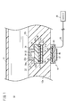
- the sensor system 10 includes a first transmission/reception unit 16 provided inside the medical device 12 having a blood flow path 14, and a second transmission/reception unit 18 mounted outside the medical device 12. I have it.
- the first transmission/reception unit 16 and the second transmission/reception unit 18 are configured to perform contactless power supply and signal transmission/reception without wiring.
- the first transmission/reception unit 16 includes a sensor unit 22, a semiconductor substrate 28, and a coil built-in substrate 42.
- the sensor unit 22 includes a piezoresistive semiconductor pressure sensor 22a having a hollow portion 24 therein, and the hollow portion 24 is kept in a vacuum state, and can detect an absolute pressure. As a result, it is possible to eliminate the need for calibration work for each measurement.
- the sensor unit 22 shows a change in resistance value according to the external pressure by distorting the upper end portion toward the cavity portion 24 according to the pressure difference between the cavity portion 24 and the outside. Further, the sensor unit 22 is provided with a sensor amplifier that converts the resistance change of the piezoresistive semiconductor pressure sensor 22a into a voltage value and outputs the voltage value.
- the sensor portion 22 including the sensor amplifier and the piezoresistive semiconductor pressure sensor 22a is bonded to the main surface 28a (upper surface) of the semiconductor substrate 28.
- the sensor unit 22 and the semiconductor substrate 28 are covered with a protective layer 26 made of resin or the like.
- the semiconductor substrate 28 is formed with an A / D converter 23 and a transmission / reception circuit 25.
- the A / D converter 23 is electrically connected to the sensor unit 22 and the transmission / reception circuit 25, converts the output voltage of the sensor amplifier of the sensor unit 22 into a digital signal, and outputs the output voltage to the transmission / reception circuit 25.
- the transmission / reception circuit 25 is electrically connected to the first coil 32.
- the transmission/reception circuit 25 converts the power supplied via the first coil 32 into a predetermined voltage and supplies the voltage to the sensor unit 22 and the A/D converter 23.
- the transmission / reception circuit 25 modulates the digital signal received from the A / D converter 23 into a signal having a predetermined frequency, and transmits the digital signal to the second transmission / reception unit 18 via the first coil 32.
- the A/D converter 23 and the transmission/reception circuit 25 are formed on the main surface 28a (upper surface) or lower surface of the semiconductor substrate 28 by a semiconductor manufacturing process.
- the coil-embedded substrate 42 is bonded to the lower surface side of the semiconductor substrate 28.
- the coil-embedded substrate 42 is a multilayer substrate formed by laminating a plurality of resin layers 41a and 41b, and the first coil 32 formed in a flat plate shape is embedded between the resin layers 41a and 41b. That is, the first coil 32 is formed flat in a direction parallel to the main surfaces of the semiconductor substrate 28 and the coil-embedded substrate 42, and the winding axis of the first coil 32 is perpendicular to the semiconductor substrate 28 and the coil-embedded substrate 42. Facing the right direction.
- the first coil 32 is formed on the resin layer 41a as a spiral conductor pattern, for example.
- the coil-embedded substrate 42 including the first coil 32 is manufactured by, for example, a build-up method.
- a via hole 41c penetrating the resin layer 41b in the thickness direction is formed at one end and the other end of the first coil 32.
- a conductor 32a made of copper or the like is embedded in the via hole 41c.
- the first coil 32 is electrically connected to the semiconductor substrate 28 via a conductor 32a embedded in the via hole 41c.
- the first transmitting/receiving unit 16 is arranged so that the sensor unit 22 is adjacent to the blood flow path 14.
- the first transmission / reception unit 16 is housed in a recess 12b formed in a side wall 12a of a medical device 12 (tube) having a blood flow path 14.
- the first transmission / reception unit 16 is attached to the inside of the medical device 12 so as not to protrude from the inner wall 12c of the medical device 12. That is, it is preferable to arrange the upper end of the sensor unit 22 of the first transmitting/receiving unit 16 so as to be flush with the inner wall 12c of the medical device 12.
- the coil-embedded substrate 42 can be formed in a rectangular shape of, for example, about 2 mm square to 5 mm square. The larger the area of the coil-embedded substrate 42, the larger the area of the first coil 32, which facilitates power supply and signal transmission / reception from the second transmission / reception unit 18.
- the semiconductor substrate 28 may have a size equal to or smaller than the coil-embedded substrate 42.
- the second transmission/reception unit 18 includes a second coil 36, a coil substrate 44, a circuit element 46, and a connection wiring 52.
- the coil substrate 44 is a substrate made of a single resin, a fiber reinforced resin, or ceramics, and a second coil 36 wound in a plane as a spiral pattern is formed on one surface thereof.
- the second coil 36 is formed in a plane along the main surface of the coil substrate 44, and the winding axis is oriented in the vertical direction of the coil substrate 44.
- the second coil 36 and the coil substrate 44 are covered with the coating resin 45.
- the circuit element 46 is mounted on the other surface of the coil board 44. As shown in FIG. 2, the circuit element 46 includes a transmission/reception circuit 38 and an input/output unit 40.
- the transmission/reception circuit 38 is electrically connected to the second coil 36, supplies electric power for driving the second coil 36, and receives a detection signal of the first transmission/reception unit 16 via the second coil 36.
- the input / output unit 40 is connected to the control device 20 through the connection wiring 52.
- the input / output unit 40 is configured to receive the control signal from the control device 20 and transmit the measurement data of the first transmission / reception unit 16 to the control device 20.
- the transmission / reception circuit 38 of the circuit element 46 and the input / output unit 40 may be formed on the same semiconductor chip, or those formed on different semiconductor chips may be formed on the coil substrate 44. It may be configured by being electrically connected with. The lower surfaces of the circuit element 46 and the coil substrate 44 are covered with the resin layer 47.
- connection wiring 52 includes a plurality of conductor wires and supplies the power required for the operation of the second transmission / reception unit 18. Further, the connection wiring 52 is configured to transmit a signal between the control device 20 and the second transmission / reception unit 18.
- the above-mentioned second transmitting/receiving unit 18 is detachably arranged in a direction in which the second coil 36 is parallel to the first coil 32 and at a position where the second coil 36 faces the first coil 32.
- the direction in which the second coil 36 is parallel to the first coil 32 is not limited to the direction in which the second coil 36 and the first coil 32 are strictly parallel, and the second coil 36 may be the first coil.
- the case in which it is slightly inclined with respect to 32 is also included. That is, the second coil 36 may be tilted within a range in which the first coil 32 can generate the electric power required for the operation of the first transmission/reception unit 16.
- the sensor system 10 operates so as to detect the pressure in the blood flow path 14 of the medical device 12 at a predetermined sampling frequency.
- the sampling frequency can be, for example, 10 Hz.
- the second transmission/reception unit 18 starts the generation of the electromagnetic field based on the measurement start signal.
- the measurement start signal is transmitted from the control device 20 to the second transmission / reception unit 18 via the connection wiring 52 for each sampling cycle.
- the transmission/reception circuit 38 When the transmission/reception circuit 38 receives the measurement start signal via the input/output unit 40, it supplies an alternating current having a predetermined frequency to the second coil 36, and causes the second coil 36 to generate an electromagnetic field having a predetermined frequency.
- the frequency of the electromagnetic field generated by the second coil 36 can be, for example, about 135 kHz.
- the generation of the electromagnetic field from the second coil 36 is continued until the reception of the measurement start signal from the second transmission / reception unit 18 is completed.
- step S12 the first transmission/reception unit 16 receives the electromagnetic field of the second coil 36 and is activated.
- a magnetic flux 50 is generated around the second coil 36 due to the alternating current flowing through the second coil 36.
- An alternating current is generated in the first coil 32 by electromagnetic induction through the magnetic flux 50.
- the alternating current generated in the first coil 32 is converted into direct current power having a predetermined voltage in the transmission/reception circuit 25 provided on the semiconductor substrate 28, and the power is supplied to the A/D converter 23 and the sensor unit 22. As a result, the first transmission/reception unit 16 is activated.
- the first transmission / reception unit 16 acquires the detected value of the sensor unit 22. That is, the sensor unit 22 outputs a voltage value corresponding to the pressure difference between the piezoresistive semiconductor pressure sensor 22a and the cavity portion 24 to the A / D converter 23.
- the A / D converter 23 converts the output voltage of the sensor unit 22 into a digital signal and transmits it to the transmission / reception circuit 25.
- step S16 the first transmission/reception unit 16 transmits the detection value of the sensor unit 22. That is, the transmission/reception circuit 25 of the first transmission/reception unit 16 modulates the digital signal into a predetermined frequency and transmits it from the first coil 32.
- step S18 the second transmission/reception unit 18 receives the detection value of the sensor unit 22.
- the transmission signal of the first transmission / reception unit 16 is received by the transmission / reception circuit 38 of the second transmission / reception unit 18 through the second coil 36 by electromagnetic induction.
- step S20 the second transmission/reception unit 18 outputs the detection value of the sensor unit 22 to the control device 20. That is, the detection signal received by the transmission/reception circuit 38 is input to the input/output unit 40, converted into a predetermined data format, and then transmitted to the control device 20 via the connection wiring 52.
- step S22 the second transmission/reception unit 18 stops the generation of the electromagnetic field through the second coil 36.
- the operation of the sensor system 10 in one sampling is completed.
- the sensor system 10 repeats the operations of steps S10 to S22 described above every sampling cycle.
- the sensor system 10 can be used for the medical device 60.
- the medical device 60 includes a blood pump 62 and a medical device 12 (tube) connected to the inlet or outlet of the blood pump 62.
- a first transmission / reception unit 16 is provided inside the medical device 12 (tube).
- a second transmitting/receiving unit 18 is detachably attached to the outside of the medical device 12 (tube).
- the medical device 12 (tube) is provided with a guide portion 12s including a groove or a recess for mounting the second transmitting/receiving unit 18 at a predetermined position. As shown in the figure, by mounting the second transmitting/receiving unit 18 on the guide portion 12s, the pressure inside the medical device 60 can be measured.
- the medical instrument 12 (tube) is connected to the inlet and the outlet of the blood pump 62, respectively.
- a first transceiver unit 16 is provided inside each medical device 12 (tube).
- the second transmitting/receiving unit 18 is attached to the first transmitting/receiving unit 16 on one side.
- the connection wiring 52 can be minimized. Therefore, in the medical device 60A, the connection wiring 52 is simplified and the handling property in the medical field is improved.
- the sensor system 10 and the medical devices 60 and 60A of this embodiment have the following effects.
- the sensor system 10 is installed inside the medical device 12, and is installed in the first transmitting/receiving unit 16 that outputs a detection signal of the sensor unit 22, and is detachably installed outside the medical device 12, and is not in contact with the first transmitting/receiving unit 16.
- the second transmission/reception unit 18 for transmitting/receiving a signal is provided so that the first transmission/reception unit 16 and the second transmission/reception unit 18 are opposed to each other with the medical device 12 interposed therebetween and perform transmission/reception of a signal by electromagnetic induction.
- the first transmission/reception unit 16 provided facing the blood flow path 14 and the second transmission/reception unit 18 mounted outside the medical device 12 are connected in a contactless manner by electromagnetic induction. This ensures the electrical safety of the medical device 60.
- the first transmission/reception unit 16 is provided on the semiconductor substrate 28 (substrate) and a portion mounted on the semiconductor substrate 28 and in contact with the blood channel 14 of the medical device 12 having the blood channel 14.
- the first transmission/reception unit 16 can be thinned and downsized.
- the first transmission/reception unit 16 can be provided inside the narrow medical device 12 such as a tube.
- the second transmission/reception unit 18 has the second coil 36 wound in a plane, and the first transmission/reception unit 16 and the second transmission/reception unit 18 are the winding axes of the first coil 32. And the winding axis of the second coil 36 are arranged so as to be parallel to each other. This facilitates electromagnetic induction between the first coil 32 and the second coil 36.
- the second transmission/reception unit 18 may supply drive power to the first transmission/reception unit 16 by current induction.
- the first transmission/reception unit 16 can be operated without providing a storage battery or power supply wiring in the first transmission/reception unit 16.
- the first transmission/reception unit 16 may be configured to transmit the detection signal of the sensor unit 22 to the second transmission/reception unit 18 by electromagnetic induction.
- the device configuration can be simplified and the second transmission/reception unit 18 can be downsized.
- the sensor unit 22 may be a piezoresistive semiconductor pressure sensor 22a (pressure sensor) that detects the pressure of blood flowing in the blood flow path 14. Thereby, an abnormality due to blockage of the blood flow path 14 or the like can be detected.
- a piezoresistive semiconductor pressure sensor 22a pressure sensor
- a guide portion 12s indicating the installation position of the first transmission/reception unit 16 may be provided outside the medical device 12.
- the second transmission/reception unit 18 can be mounted at an appropriate position.
- the upper end portion of the first transmission/reception unit 16 may be attached to the inside of the medical device 12 in such a manner that it does not protrude from the inner wall 12c of the blood flow path 14. This can prevent the occurrence of thrombus in the blood flow path 14.
- the medical devices 60 and 60A described above are installed in the medical device 12 having the blood flow path 14, and the first transmission/reception unit 16 that is installed inside the blood flow path 14 of the medical device 12 and outputs the detection signal of the sensor unit 22 for detecting.
- a second transmitting/receiving unit 18 that is detachably installed outside the medical device 12 and that transmits/receives signals to/from the first transmitting/receiving unit 16 in a non-contact manner.
- the first transmitting/receiving unit 16 and the second transmitting/receiving unit 18 are The sensor system 10 is provided so as to face each other with the medical device 12 in between, and transmits and receives a signal by electromagnetic induction. As a result, the electrical safety of the medical devices 60 and 60A can be ensured. Further, since the second transmission / reception unit 18 can be removed when measurement is not necessary, the connection wiring 52 is simplified and the handleability of the medical devices 60 and 60A is improved.
- the sensor unit 22 has been shown as an example of the pressure sensor using the piezoresistive semiconductor pressure sensor 22a, the present invention is not limited to this.
- the sensor unit 22 may be a temperature sensor that detects the temperature of blood, or may include an electrochemical sensor that detects a predetermined blood component by an electrochemical reaction with blood. Further, the sensor unit 22 may be a sensor that detects various characteristics such as magnetic characteristics, optical characteristics, and viscosity of blood.
Landscapes
- Health & Medical Sciences (AREA)
- Heart & Thoracic Surgery (AREA)
- Vascular Medicine (AREA)
- General Health & Medical Sciences (AREA)
- Veterinary Medicine (AREA)
- Anesthesiology (AREA)
- Biomedical Technology (AREA)
- Hematology (AREA)
- Life Sciences & Earth Sciences (AREA)
- Animal Behavior & Ethology (AREA)
- Engineering & Computer Science (AREA)
- Public Health (AREA)
- Cardiology (AREA)
- Physics & Mathematics (AREA)
- General Physics & Mathematics (AREA)
- Fluid Mechanics (AREA)
- Emergency Medicine (AREA)
- Urology & Nephrology (AREA)
- External Artificial Organs (AREA)
- Measuring Pulse, Heart Rate, Blood Pressure Or Blood Flow (AREA)
Priority Applications (3)
| Application Number | Priority Date | Filing Date | Title |
|---|---|---|---|
| EP20766359.2A EP3919096A4 (en) | 2019-03-07 | 2020-02-14 | SENSOR SYSTEM AND MEDICAL DEVICE |
| JP2021503513A JP7422733B2 (ja) | 2019-03-07 | 2020-02-14 | センサシステム及び医療デバイス |
| US17/400,558 US12311094B2 (en) | 2019-03-07 | 2021-08-12 | Sensor system and medical device |
Applications Claiming Priority (2)
| Application Number | Priority Date | Filing Date | Title |
|---|---|---|---|
| JP2019041317 | 2019-03-07 | ||
| JP2019-041317 | 2019-03-07 |
Related Child Applications (1)
| Application Number | Title | Priority Date | Filing Date |
|---|---|---|---|
| US17/400,558 Continuation US12311094B2 (en) | 2019-03-07 | 2021-08-12 | Sensor system and medical device |
Publications (1)
| Publication Number | Publication Date |
|---|---|
| WO2020179411A1 true WO2020179411A1 (ja) | 2020-09-10 |
Family
ID=72338270
Family Applications (1)
| Application Number | Title | Priority Date | Filing Date |
|---|---|---|---|
| PCT/JP2020/005753 Ceased WO2020179411A1 (ja) | 2019-03-07 | 2020-02-14 | センサシステム及び医療デバイス |
Country Status (4)
| Country | Link |
|---|---|
| US (1) | US12311094B2 (https=) |
| EP (1) | EP3919096A4 (https=) |
| JP (1) | JP7422733B2 (https=) |
| WO (1) | WO2020179411A1 (https=) |
Citations (6)
| Publication number | Priority date | Publication date | Assignee | Title |
|---|---|---|---|---|
| JPH0346729Y2 (https=) * | 1987-04-06 | 1991-10-03 | ||
| US20070179433A1 (en) * | 2004-02-12 | 2007-08-02 | Lennart Jonsson | Pressure sensing |
| US20130303967A1 (en) * | 2010-06-17 | 2013-11-14 | University Of Virginia Patent Foundation | Meters for in-vivo monitoring |
| US20140243703A1 (en) * | 2011-02-16 | 2014-08-28 | Alfred E. Mann Foundation For Scientific Research | Implantable shunt system and associated pressure sensors |
| US20140276346A1 (en) * | 2013-03-14 | 2014-09-18 | Siddharth Sadanand | Shunt flow monitor |
| JP2018510000A (ja) | 2015-03-31 | 2018-04-12 | メドトロニック・ピーエス・メディカル・インコーポレーテッド | シャントに関する無線圧力測定およびモニタリング |
Family Cites Families (3)
| Publication number | Priority date | Publication date | Assignee | Title |
|---|---|---|---|---|
| EP2916120A1 (de) * | 2014-03-04 | 2015-09-09 | seleon GmbH | Sensorblock, Rohr sowie Herstellungsverfahren |
| JP6684897B2 (ja) * | 2015-09-03 | 2020-04-22 | コーニンクレッカ フィリップス エヌ ヴェKoninklijke Philips N.V. | データ及び/又は電力のワイヤレス伝送のためのコネクタ及びデバイス |
| JP6857095B2 (ja) * | 2017-07-05 | 2021-04-14 | サーパス工業株式会社 | 圧力検出装置 |
-
2020
- 2020-02-14 JP JP2021503513A patent/JP7422733B2/ja active Active
- 2020-02-14 EP EP20766359.2A patent/EP3919096A4/en active Pending
- 2020-02-14 WO PCT/JP2020/005753 patent/WO2020179411A1/ja not_active Ceased
-
2021
- 2021-08-12 US US17/400,558 patent/US12311094B2/en active Active
Patent Citations (6)
| Publication number | Priority date | Publication date | Assignee | Title |
|---|---|---|---|---|
| JPH0346729Y2 (https=) * | 1987-04-06 | 1991-10-03 | ||
| US20070179433A1 (en) * | 2004-02-12 | 2007-08-02 | Lennart Jonsson | Pressure sensing |
| US20130303967A1 (en) * | 2010-06-17 | 2013-11-14 | University Of Virginia Patent Foundation | Meters for in-vivo monitoring |
| US20140243703A1 (en) * | 2011-02-16 | 2014-08-28 | Alfred E. Mann Foundation For Scientific Research | Implantable shunt system and associated pressure sensors |
| US20140276346A1 (en) * | 2013-03-14 | 2014-09-18 | Siddharth Sadanand | Shunt flow monitor |
| JP2018510000A (ja) | 2015-03-31 | 2018-04-12 | メドトロニック・ピーエス・メディカル・インコーポレーテッド | シャントに関する無線圧力測定およびモニタリング |
Also Published As
| Publication number | Publication date |
|---|---|
| US12311094B2 (en) | 2025-05-27 |
| EP3919096A1 (en) | 2021-12-08 |
| EP3919096A4 (en) | 2022-04-13 |
| JP7422733B2 (ja) | 2024-01-26 |
| US20210369935A1 (en) | 2021-12-02 |
| JPWO2020179411A1 (https=) | 2020-09-10 |
Similar Documents
| Publication | Publication Date | Title |
|---|---|---|
| EP2414789B1 (en) | Flow meter with ultrasound transducer directly connected to and fixed to measurement circuit board | |
| US8085143B2 (en) | Universal wireless transceiver | |
| KR101559215B1 (ko) | 바이오센서 패키지 및 그 제조 방법 | |
| KR102444522B1 (ko) | 위치 지시기 | |
| US20060241354A1 (en) | Electromagnetically coupled hermetic chamber | |
| US20100176904A1 (en) | Current detection printed board, voltage detection printed board, and current/voltage detector using same, and current detector and voltage detector | |
| JP2007313594A (ja) | 積層デバイス、およびその製造方法 | |
| CN103080737A (zh) | 用于感测流体性质的方法和设备 | |
| EP0334611A2 (en) | Pressure transmitter assembly | |
| CN112786561B (zh) | 部件承载件及其制造方法 | |
| CN104246451B (zh) | 流量计、测量管及流量计的制造方法 | |
| EP3121496B1 (en) | Positioner | |
| KR101884905B1 (ko) | 도전성 액체 누설 감지 장치 및 그 제조 방법 | |
| CN103999283B (zh) | 用于传输来自电池单元的信息的装置和方法以及电池单元 | |
| JP7422733B2 (ja) | センサシステム及び医療デバイス | |
| CN114885499B (zh) | 部件承载件及其制造方法 | |
| CN115581486A (zh) | 一种心脏分流器及左心房压力监测系统 | |
| JP2011047688A (ja) | 感圧素子及び圧力センサ | |
| JP2014066681A (ja) | 高周波検出装置、および、当該高周波検出装置を備えた高周波測定装置 | |
| CN116601638A (zh) | 声学应答器,声学应答器的应用,制造应答器的方法和声学传输系统 | |
| US11801946B2 (en) | System for sensing miniature gaps by inductive coupling | |
| US20240170409A1 (en) | Semiconductor module, semiconductor chip, and method for manufacturing semiconductor module | |
| CN112903046A (zh) | 模块化超声耗量表 | |
| KR101552777B1 (ko) | 바이오센서 패키지 및 그 제조 방법 | |
| CN218865222U (zh) | 一种液位测量系统 |
Legal Events
| Date | Code | Title | Description |
|---|---|---|---|
| 121 | Ep: the epo has been informed by wipo that ep was designated in this application |
Ref document number: 20766359 Country of ref document: EP Kind code of ref document: A1 |
|
| ENP | Entry into the national phase |
Ref document number: 2021503513 Country of ref document: JP Kind code of ref document: A |
|
| NENP | Non-entry into the national phase |
Ref country code: DE |
|
| ENP | Entry into the national phase |
Ref document number: 2020766359 Country of ref document: EP Effective date: 20210831 |