WO2020179323A1 - 電動パワーステアリング装置 - Google Patents
電動パワーステアリング装置 Download PDFInfo
- Publication number
- WO2020179323A1 WO2020179323A1 PCT/JP2020/004170 JP2020004170W WO2020179323A1 WO 2020179323 A1 WO2020179323 A1 WO 2020179323A1 JP 2020004170 W JP2020004170 W JP 2020004170W WO 2020179323 A1 WO2020179323 A1 WO 2020179323A1
- Authority
- WO
- WIPO (PCT)
- Prior art keywords
- axis
- distance
- shaft
- projection
- electric power
- Prior art date
- Legal status (The legal status is an assumption and is not a legal conclusion. Google has not performed a legal analysis and makes no representation as to the accuracy of the status listed.)
- Ceased
Links
Images



Classifications
-
- B—PERFORMING OPERATIONS; TRANSPORTING
- B62—LAND VEHICLES FOR TRAVELLING OTHERWISE THAN ON RAILS
- B62D—MOTOR VEHICLES; TRAILERS
- B62D3/00—Steering gears
- B62D3/02—Steering gears mechanical
- B62D3/12—Steering gears mechanical of rack-and-pinion type
-
- B—PERFORMING OPERATIONS; TRANSPORTING
- B62—LAND VEHICLES FOR TRAVELLING OTHERWISE THAN ON RAILS
- B62D—MOTOR VEHICLES; TRAILERS
- B62D5/00—Power-assisted or power-driven steering
- B62D5/04—Power-assisted or power-driven steering electrical, e.g. using an electric servo-motor connected to, or forming part of, the steering gear
Definitions
- the present invention relates to an electric power steering device.
- JP2001-106101A is connected to a steering shaft that rotates by receiving steering torque from a steering wheel, a pinion gear provided on the steering shaft, a rack shaft that has a rack gear that meshes with the pinion gear, and a swing shaft that is swingably connected to the rack shaft.
- Electric power steering including: a tie rod, a boot that covers the connecting portion between the rack shaft and the tie rod, a worm wheel provided on the steering shaft, a worm shaft that meshes with the worm wheel, and a drive unit that rotationally drives the worm shaft.
- a device is disclosed.
- the worm wheel to which the output of the drive unit is transmitted via the worm shaft is housed in the housing that houses the rack shaft. Therefore, the drive unit is arranged at a position close to the rack axis.
- the length in the longitudinal direction of the housing in which the rack shaft is housed can be made relatively long, so even if the drive unit is arranged along the rack shaft for compactness, It is easy to prevent the boot and the drive unit from interfering with each other when the tie rod swings.
- the longitudinal length of the housing that houses the rack shaft is limited. A part of the part protrudes outward in the axial direction of the housing. If a part of the drive unit protrudes outward in the axial direction in this way, the boot and the drive unit may interfere with each other when the tie rod swings significantly.
- the swing angle of the tie rod is larger than that of general passenger vehicles. Although it is set, the swing range of the tie rod may be limited due to the interference between the boot and the drive unit.
- An object of the present invention is to secure a sufficient swing range of a tie rod in an electric power steering device.
- the electric power steering apparatus has a steering shaft that receives a steering torque from a steering wheel to rotate, a pinion gear that is provided on the steering shaft, and a rack shaft that has a rack gear that meshes with the pinion gear.
- a pair of tie rods that are swingably connected to the rack shaft, a boot that covers a connecting portion between the rack shaft and the tie rod, a worm wheel provided on the steering shaft, and a worm shaft that meshes with the worm wheel.
- a drive unit that rotationally drives the worm shaft, and includes a first plane that is parallel to a second axis that is a rotation center of the worm shaft and that includes a first axis that is a rotation center of the pinion gear and the worm wheel.
- An end point of the drive unit on the second axis from a first intersection point where a first projection axis line obtained by projecting the second axis line on the first projection plane and the first axis line as a projection plane Is defined as a first distance
- a plane including the first axis and parallel to a third axis which is a movement center of the rack shaft is defined as a second projection plane
- the third axis is defined as the second projection plane in the second projection plane.
- the distance to be performed is the second distance and the distance from the second intersection to the second swing center which is the swing center of the other tie rod and changes due to the displacement of the rack shaft is the third distance.
- the first distance is longer than at least one of the minimum value of the second distance and the minimum value of the third distance, and the drive unit causes the boot to operate even when the tie rod is most swung. It is placed in a position that does not interfere with.
- FIG. 1 is a configuration diagram of an electric power steering device according to an embodiment of the present invention.
- FIG. 2 is an external view of the electric power steering device according to the embodiment of the present invention.
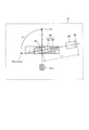
- FIG. 3 is a schematic diagram showing the relationship between the first axis and the second axis projected on the first projection surface.
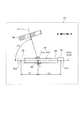
- FIG. 4 is a schematic diagram showing the relationship between the first axis and the third axis projected on the second projection surface.
- FIG. 5 is a schematic diagram showing the relationship between the first axis, the second axis, and the third axis projected on the third projection surface.
- FIG. 1 is a configuration diagram of an electric power steering device 100
- FIG. 2 is an external view of the electric power steering device 100 assembled in a vehicle as seen from the rear of the vehicle.
- the electric power steering device 100 is a device that is installed in a vehicle and that assists a steering force with respect to a steering device that steers wheels 1 by converting a steering torque applied to a steering wheel 10 as a steering wheel by a driver. ..
- the vehicle to which the electric power steering device 100 is assembled is an all-terrain vehicle (ATV: All Terrain Vehicle) or a versatile four-wheel vehicle (SSV:Side by Side Vehicle) with a relatively narrow vehicle width is described. To do.
- ATV All Terrain Vehicle
- SSV Stevial by Side Vehicle
- the electric power steering device 100 includes a steering shaft 20 that rotates by a steering torque input from the steering wheel 10, a rack shaft 30 that steers the wheels 1 as the steering shaft 20 rotates, and a rack shaft 30. Equipped with.
- the steering shaft 20 is a torsion bar that connects an input shaft 21 that rotates with a steering operation in which the driver operates the steering wheel 10, an output shaft 22 that displaces the rack shaft 30, and the input shaft 21 and the output shaft 22. 23 and.
- the rack shaft 30 is a shaft-shaped member that extends in the left-right direction of the vehicle and is connected to the wheel 1 via a tie rod 31 and a knuckle arm 32.
- the tie rods 31 are swingably connected to the rack shaft 30 via ball joints 33 as connecting portions provided at both ends of the rack shaft 30, and the swing center which is a rotation center of the ball joint 33.
- the vehicle can swing over a predetermined swing range SR in the vertical direction and the front-back direction of the vehicle.
- the connecting portion that connects the rack shaft 30 and the tie rod 31 is not limited to the ball joint 33, and other types of universal joints may be used.
- the output shaft 22 and the rack shaft 30 are connected to each other via a transmission unit 41.
- the transmission unit 41 is a rack and pinion mechanism including a pinion gear 41a provided on the end of the output shaft 22 and a rack gear 41b provided on the rack shaft 30.
- the pinion gear 41a and the rack gear 41b mesh with each other, and the torque of the output shaft 22 is converted into an axial load of the rack shaft 30 and transmitted to the rack shaft 30 via the pinion gear 41a and the rack gear 41b.
- the rack shaft 30 is displaced in the axial direction by the transmitted torque and steers the wheel 1 via the tie rod 31 and the knuckle arm 32.
- the electric power steering device 100 includes an electric motor 50 as a drive unit driven in response to a steering operation, and a speed reduction unit 42 that decelerates the rotation of the electric motor 50 and transmits it to the steering shaft 20.
- the reduction unit 42 is a worm gear mechanism including a worm shaft 43 driven by the electric motor 50 and a worm wheel 44 provided on the output shaft 22.
- the worm shaft 43 and the worm wheel 44 mesh with each other, and the torque of the electric motor 50 is transmitted to the output shaft 22 via the worm shaft 43 and the worm wheel 44.
- the torque transmitted from the electric motor 50 to the output shaft 22 is further transmitted to the rack shaft 30 via the pinion gear 41a and the rack gear 41b.
- the electric power steering device 100 includes a torque sensor 62 that detects the torque acting on the torsion bar 23, and a controller 60 as a drive unit that controls the drive of the electric motor 50 according to the detection value of the torque sensor 62. Further prepare.
- the controller 60 includes a CPU (Central Processing Unit) that performs arithmetic processing, a ROM (Read-Only Memory) that stores a control program executed by the CPU, and a RAM (random access memory) that stores the arithmetic result of the CPU. And a microcomputer including.
- the controller 60 may be composed of a single microcomputer or may be composed of a plurality of microcomputers.
- the torque sensor 62 detects the steering torque applied to the input shaft 21 in accordance with the steering operation by the driver, and outputs a voltage signal corresponding to the detected steering torque to the controller 60.
- the controller 60 calculates the torque output by the electric motor 50 based on the voltage signal from the torque sensor 62, and controls the drive of the electric motor 50 so that the torque is generated.
- the electric power steering apparatus 100 detects the steering torque applied to the input shaft 21 by the torque sensor 62 and controls the drive of the electric motor 50 by the controller 60 on the basis of the detection result. Assist steering operation.
- the electric power steering device 100 further includes a rack housing 34 as a housing portion for housing the rack shaft 30 and a worm housing 45 as a housing portion for housing the worm wheel 44.
- the rack housing 34 accommodates the rack shaft 30 and the pinion gear 41 a provided on the output shaft 22.
- a stopper (not shown) is formed in the rack housing 34 with which a regulation surface (not shown) provided on the ball joint 33 coupled to the rack shaft 30 abuts, and the movement of the rack shaft 30 in the axial direction is performed by the ball joint 33. It is limited by the contact of the regulating surface of the with the stopper.
- boots 35 are attached to the ends of the rack housing 34 in order to protect the ball joint 33 and prevent water and the like from entering the rack housing 34.
- the boot 35 is a tubular member made of rubber or resin (elastomer), and has one end fastened to the end of the rack housing 34 and the other end fastened to the tie rod 31.
- the worm housing 45 accommodates the worm wheel 44, the output shaft 22 provided with the worm wheel 44, and the worm shaft 43 that meshes with the worm wheel 44.
- An electric motor 50 that drives the worm shaft 43 is attached to the worm housing 45, and a controller 60 that controls the drive of the electric motor 50 is attached to the electric motor 50.
- the controller 60 may be assembled between the worm shaft 43 and the electric motor 50 or on the outer peripheral surface of the electric motor 50.
- the worm housing 45 is arranged above the rack housing 34 in the vertical direction when the electric power steering device 100 is assembled to the vehicle. In this way, since the worm housing 45 is arranged above the rack housing 34 in the vertical direction, the worm housing 45 is used even when traveling in a river or the like having a certain depth of water, such as an all-terrain vehicle. The water can be prevented from entering the worm housing 45 and the water can enter the electric motor 50 assembled to the worm housing 45 as compared with the case where the water is arranged vertically below the rack housing 34. Can be prevented.
- the rack housing 34 and the worm housing 45 are made of separate members, but the rack housing 34 and the worm housing 45 may be integrally formed.
- the rack housing 34 and the worm housing 45 hold the rack shaft 30, the pinion gear 41a, the worm shaft 43, and the worm wheel 44, so that the first axis CL1 that is the rotation center of the pinion gear 41a and the worm wheel 44.
- FIG. 3 shows the first axis CL1 projected onto the first projection plane P1 parallel to the second axis CL2 which is the rotation center of the worm shaft 43 and which includes the first axis CL1 which is the rotation center of the pinion gear 41a and the worm wheel 44.
- FIG. 4 is a schematic diagram showing a relationship with the second axis CL2, and FIG. 4 shows a first projection line P2 projected onto a second projection plane P2 parallel to the third axis CL3 which is the movement center of the rack shaft 30 and includes the first axis CL1.
- FIG. 3 shows the first axis CL1 projected onto the first projection plane P1 parallel to the second axis CL2 which is the rotation center of the worm shaft 43 and which includes the first axis CL1 which is the rotation center of the pinion gear 41a and the worm wheel 44.
- FIG. 4 is a schematic diagram showing a relationship with the second axis CL2, and FIG. 4 shows a first projection line P2 projected onto a second projection plane P2 parallel to
- FIG. 5 is a schematic diagram showing the relationship between the first axis CL1 and the third axis CL3, and FIG. 5 shows the relationship between the second axis CL2 and the third axis CL3 projected on the third projection plane P3 orthogonal to the first axis CL1. It is a schematic diagram which showed the relationship.
- a predetermined first angle ⁇ 1 is formed between the first axis CL1 and the first projection axis PCL1 on which the second axis CL2 is projected on the first projection plane P1.
- the electric motor 50 and the controller 60 arranged on the second axis CL2 are close to the pinion gear 41a arranged on the first axis CL1, that is, , The electric motor 50 and the controller 60 are brought close to the rack housing 34.
- the electric motor 50 and the controller 60 are separated from the rack housing 34.
- the output shaft 22 and the worm shaft 43 are in a state of being orthogonal to each other.
- a predetermined second angle ⁇ 2 is formed between the first axis CL1 and the second projection axis PCL2 on which the third axis CL3 is projected on the second projection plane P2.
- a predetermined third angle ⁇ 3 is formed between the.
- the electric motor 50 and the controller 60 arranged on the second axis line CL2 have the longitudinal direction of the rack housing 34. It is in a state of being arranged along the direction.
- the electric motor 50 and the controller 60 are separated from the rack housing 34.
- the electric motor 50 and the controller 60 can be arranged vertically above the rack shaft 30, that is, above the rack housing 34 in the vertical direction.
- the length of the rack housing 34 in the longitudinal direction is limited.
- the electric motor 50 and the controller 60 which are drive units, are arranged along the rack housing 34 for the sake of compactness, a part of the electric motor 50 and the controller 60 protrudes outward in the axial direction of the rack housing 34.
- a point where the first projection axis PCL1 (second axis CL2) and the first axis CL1 intersect on the first projection plane P1 is defined as a first intersection IP1, and from the first intersection IP1.
- the distance to the end points of the electric motor 50 and the controller 60 arranged on the second axis CL2 is the first distance L1
- a part of the electric motor 50 and the controller 60 does not protrude outward in the axial direction of the rack housing 34.
- the rack housing 34 needs to have an axial length exceeding the first distance L1.
- a point where the second projection axis PCL2 (third axis CL3) and the first axis CL1 intersect on the second projection plane P2 is defined as a second intersection IP2, and one of the second intersection IP2 is A distance from the second swing center SC1 which is the swing center of the other tie rod 31 to the first swing center SC1 which is the swing center of the tie rod 31 is defined as a second distance L2.
- the electric motor 50 and a part of the controller 60 are part of the shaft of the rack housing 34. There is a possibility that it may protrude outward in the direction.
- the rack housing 34 may protrude axially outside the rack housing 34 beyond the SC1 or the second swing center SC2.
- the lengths of the second distance L2 and the third distance L3 change depending on the displacement of the rack shaft 30, and when the rack shaft 30 is displaced until the movement to the right shown in FIG. 4 is restricted, the second distance L2 is the maximum value and the third distance L3 is the minimum value.
- the second distance L2 is the minimum value and the third distance L3 is the maximum value. It becomes a value.
- the swing angle of the tie rod 31 required for a general passenger car is about ⁇ 30 degrees in the vertical direction and the front-rear direction of the vehicle with reference to the third axis CL3, whereas it is required for an all-terrain vehicle. Since the swing angle of the tie rod 31 is as large as ⁇ 35 to 45 degrees, the boot 35 is likely to interfere with a part of the electric motor 50 and the controller 60. Further, if the swing range SR of the tie rod 31 is simply limited in order to avoid interference between the boot 35 and a part of the electric motor 50 and the controller 60, the traveling performance of the all-terrain vehicle will be reduced. It will be decided.
- a part of the electric motor 50 and the controller 60 is arranged beyond the swing centers SC1 and SC2 of the tie rod 31 when viewed from the direction orthogonal to the third axis CL3 which is the moving center of the rack shaft 30.
- the electric motor 50 and the controller 60 are arranged so that the boot 35 does not interfere with a part of the electric motor 50 and the controller 60 even when the tie rod 31 is most swung. It is arranged. In other words, the electric motor 50 and the controller 60 are arranged so as not to interfere with the boot 35 regardless of the set swing range SR of the tie rod 31.
- the size of the first angle ⁇ 1 shown in FIG. 3 can be made smaller than 90 degrees in order to make the electric power steering device 100 compact so that the electric motor 50 and the controller 60 can be brought closer to the rack housing 34. preferable.
- the size of the first angle ⁇ 1 is set so that the electric power steering apparatus 100 can be made compact while avoiding interference between the boot 35 and a part of the electric motor 50 and the controller 60.
- the position of the worm wheel 44 changes, and accordingly, the worm shaft 43 meshing with the worm wheel 44 and the worm shaft 43 are coaxially arranged.
- the positions of the electric motor 50 and the controller 60 that are operated also change. Therefore, by changing the size of the second angle ⁇ 2, the positions of the electric motor 50 and the controller 60 can be changed to prevent the boots 35 from interfering with a part of the electric motor 50 and the controller 60. It is possible.
- the size of the third angle ⁇ 3 shown in FIG. 5 is set to zero in order to make the electric power steering device 100 compact, so that the electric motor 50 and the controller 60 are set along the longitudinal direction of the rack housing 34. It is preferable that the electric motor 50 and the controller 60 are arranged above the rack housing 34 in the vertical direction by arranging the electric motor 50 and the controller 60 with a predetermined size. On the other hand, when the electric motor 50 and the controller 60 are arranged relatively close to the rack housing 34, a part of the electric motor 50 and the controller 60 and the boot 35 are likely to interfere with each other.
- the size of the third angle ⁇ 3 is set so that the electric power steering apparatus 100 can be made compact while avoiding interference between the boot 35 and a part of the electric motor 50 and the controller 60.
- the size of the third angle ⁇ 3 is about 90 degrees and the electric motor 50 and the controller 60 are arranged at the position farthest from the rack housing 34. ..
- At least one of the magnitudes of the first angle ⁇ 1, the second angle ⁇ 2, and the third angle ⁇ 3 is the electric motor even when the tie rod 31 swings most in the preset swing range SR. It is appropriately set so that a part of the 50 and the controller 60 and the boot 35 do not interfere with each other.
- the first angle ⁇ 1, the second angle ⁇ 2, and the third angle ⁇ 1, the second angle ⁇ 2, and the third angle so as not to interfere with a part of the electric motor 50 and the controller 60 and the boot 35 even when the tie rod 31 swings most.
- At least one of the angles ⁇ 3 is set. Therefore, there is a possibility that a part of the electric motor 50 and the controller 60 is arranged beyond the swing centers SC1 and SC2 of the tie rod 31 when viewed from the direction orthogonal to the third axis CL3 which is the moving center of the rack shaft 30. Even in the electric power steering device 100, it is possible to prevent the boots 35 from interfering with a part of the electric motor 50 and the controller 60. As a result, the swing range SR of the tie rod 31 can be sufficiently secured.
- the worm shaft 43 is arranged so as to mesh with the worm wheel 44 on the same side as the rack shaft 30 with respect to the first axis CL1 as shown in FIG. It may be arranged so as to mesh with the worm wheel 44 on the side opposite to the rack shaft 30 with respect to the one axis CL1.
- the worm housing 45 is arranged above the rack housing 34 in the vertical direction.
- the worm housing 45 may be arranged vertically below the rack housing 34. As a result, the space below the rack housing 34 in the vertical direction can be effectively used.
- the output of the electric motor 50 is given to the output shaft 22 connected to the input shaft 21 that rotates in accordance with the steering operation.
- the shaft to which the output of the electric motor 50 is given is not limited to this.
- the electric motor is attached to the output shaft. Fifty outputs may be provided.
- the steering handle is the steering wheel 10.
- the steering handle may be of some other form, such as a bar handle or control stick.
- the electric power steering device 100 includes a steering shaft 20 that receives a steering torque from the steering wheel 10 to rotate, a pinion gear 41 a provided on the steering shaft 20, a rack shaft 30 having a rack gear 41 b that meshes with the pinion gear 41 a, and a rack shaft 30.
- a pair of tie rods 31 that are swingably connected to the steering shaft 30, boots 35 that cover the connecting portion between the rack shaft 30 and the tie rod 31, a worm wheel 44 provided on the steering shaft 20, and a worm shaft that meshes with the worm wheel 44.
- an electric motor 50 that rotationally drives the worm shaft 43, and a controller 60 and includes a first axis CL1 that is the rotation center of the pinion gear 41a and the worm wheel 44 and a second axis CL2 that is the rotation center of the worm shaft 43.
- the plane parallel to the first projection plane P1 is defined as the first projection plane P1
- the first projection plane PC1 projects the second axis CL2 onto the first projection plane P1.
- the distance to the end points of the electric motor 50 and the controller 60 on the two-axis line CL2 is defined as the first distance L1
- the plane parallel to the third axis CL3 including the first axis CL1 and the moving center of the rack shaft 30 is the second projection plane.
- P2 is the swing center of one tie rod 31 from the second intersection point IP2 at which the second projection axis PCL2 obtained by projecting the third axis CL3 on the second projection surface P2 and the first axis CL1 intersect on the second projection surface P2.
- a distance to the first swing center SC1 that changes depending on the displacement of the rack shaft 30 is defined as a second distance L2, and from the second intersection IP2 to the second swing center SC2 which is the swing center of the other tie rod 31.
- the first distance L1 is calculated from at least one of the minimum value of the second distance L2 and the minimum value of the third distance L3.
- the electric motor 50 and the controller 60 are arranged so as not to interfere with the boot 35 even when the tie rod 31 swings most.
- the electric motor 50 and the controller 60 are arranged so that the boot 35 does not interfere with a part of the electric motor 50 and the controller 60 even when the tie rod 31 is most swung. Therefore, there is a possibility that a part of the electric motor 50 and the controller 60 is arranged beyond the swing centers SC1 and SC2 of the tie rod 31 when viewed from the direction orthogonal to the third axis CL3 which is the moving center of the rack shaft 30. Even in the electric power steering device 100, it is possible to prevent the boots 35 from interfering with a part of the electric motor 50 and the controller 60. As a result, the swing range SR of the tie rod 31 can be sufficiently secured.
- the first distance L1 is longer than the minimum value of the second distance L2 and the minimum value of the third distance L3.
- a part of the electric motor 50 and the controller 60 is arranged so as to exceed the swing centers SC1 and SC2 of the tie rod 31.
- the electric motor 50 and the controller 60 are arranged so that a part of the electric motor 50 and the controller 60 and the boot 35 do not interfere with each other even when the tie rod 31 swings most. In this way, by avoiding interference between a part of the electric motor 50 and the controller 60 and the boot 35, it is possible to sufficiently secure the swing range SR of the tie rod 31.
- the minimum value of the second distance L2 and the minimum value of the third distance L3 are set shorter than the first distance L1. Therefore, the rack housing 34 accommodating the rack shaft 30 can be made compact, and as a result, the mountability of the electric power steering device 100 on the vehicle can be improved.
- the angle formed by the first projection axis PCL1 and the first axis CL1 on the first projection plane P1 is defined as a first angle ⁇ 1, and the angle formed by the second projection axis PCL2 and the first axis CL1 on the second projection plane P2.
- a second angle ⁇ 2 a plane orthogonal to the first axis CL1 is defined as a third projection plane P3, and a third projection axis PCL3 and a third axis P3 in which the second axis CL2 is projected on the third projection plane P3.
- the angle formed by the fourth projection axis PCL4 projecting CL3 onto the third projection plane P3 is the third angle ⁇ 3, at least one of the first angle ⁇ 1, the second angle ⁇ 2, and the third angle ⁇ 3. Is set to such a size that the electric motor 50 and the controller 60 and the boots 35 do not interfere with each other even when the tie rod 31 swings most.
- the first angle ⁇ 1, the second angle ⁇ 2, and the third angle ⁇ 3 are set so that a part of the electric motor 50 and the controller 60 and the boot 35 do not interfere with each other even when the tie rod 31 swings most. At least one of the sizes is set. Therefore, there is a possibility that a part of the electric motor 50 and the controller 60 is arranged beyond the swing centers SC1 and SC2 of the tie rod 31 when viewed from the direction orthogonal to the third axis CL3 which is the moving center of the rack shaft 30. Even in the electric power steering device 100, it is possible to prevent the boots 35 from interfering with a part of the electric motor 50 and the controller 60. As a result, the swing range SR of the tie rod 31 can be sufficiently secured.
- tie rod 31 can swing over 30 ° with reference to the third axis CL3.
- the electric motor 50 and the boot 35 are prevented from interfering with a part of the electric motor 50 and the controller 60 even when the tie rod 31 swings beyond 30 ° with respect to the third axis CL3.
- the controller 60 is arranged. Therefore, even in a vehicle in which the swing range SR of the tie rod 31 is comparatively large, for example, an all-terrain vehicle, the swing range SR of the tie rod 31 can be sufficiently secured.
Landscapes
- Engineering & Computer Science (AREA)
- Chemical & Material Sciences (AREA)
- Combustion & Propulsion (AREA)
- Transportation (AREA)
- Mechanical Engineering (AREA)
- Power Steering Mechanism (AREA)
Abstract
電動パワーステアリング装置(100)は、第1投影面(P1)において、第1投影軸線(PCL1)と第1軸線(CL1)とが交わる第1交点(IP1)から電動モータ(50)及びコントローラ(60)の端点までの距離を第1距離(L1)とし、第2投影面(P2)において、第2投影軸線(PCL2)と第1軸線(CL1)とが交わる第2交点(IP2)から一方のタイロッド(31)の第1揺動中心(SC1)までの距離を第2距離(L2)とし、第2交点(IP2)から他方のタイロッド(31)の第2揺動中心(SC2)までの距離を第3距離(L3)とした場合に、第1距離(L1)は、第2距離(L2)の最小値及び第3距離(L3)の最小値の少なくとも何れかよりも長く、電動モータ(50)及びコントローラ(60)は、タイロッド(31)が最も揺動したときであってもブーツ(35)と干渉しない位置に配置される。
Description
本発明は、電動パワーステアリング装置に関するものである。
JP2001-106101Aには、操舵ハンドルから操舵トルクが入力されて回転するステアリングシャフトと、ステアリングシャフトに設けられるピニオンギヤと、ピニオンギヤに噛み合うラックギヤを有するラック軸と、ラック軸に対して揺動自在に連結されるタイロッドと、ラック軸とタイロッドとの連結部を覆うブーツと、ステアリングシャフトに設けられるウォームホイールと、ウォームホイールと噛み合うウォームシャフトと、ウォームシャフトを回転駆動する駆動部と、を備えた電動パワーステアリング装置が開示されている。
JP2001-106101Aに記載の電動パワーステアリング装置では、ウォーム軸を介して駆動部の出力が伝達されるウォームホイールは、ラック軸が収容されるハウジングに収容される。このため、駆動部は、ラック軸から近い位置に配置されることになる。車幅が比較的広い車両では、ラック軸が収容されるハウジングの長手方向の長さを比較的長くすることができるため、コンパクト化のためにラック軸に沿って駆動部を配置させても、タイロッドが揺動した際にブーツと駆動部とが干渉しないようにすることは容易である。
一方で、車幅が比較的狭い車両では、ラック軸が収容されるハウジングの長手方向の長さが制限されることから、コンパクト化のためにラック軸に沿って駆動部を配置させると、駆動部の一部がハウジングの軸方向外側に突き出た状態となる。このように駆動部の一部がハウジングの軸方向外側に突き出た状態となると、タイロッドが大きく揺動した際にブーツと駆動部とが干渉するおそれがある。特に、比較的車幅が狭い全地形対応車(ATV : All Terrain Vehicle)や多用途四輪車(SSV : Side by Side Vehicle)では、タイロッドの揺動角が一般的な乗用車と比較して大きく設定されるが、ブーツと駆動部とが干渉することで、タイロッドの揺動範囲が制限されるおそれがある。
本発明は、電動パワーステアリング装置において、タイロッドの揺動範囲を十分確保することを目的とする。
本発明のある態様によれば、電動パワーステアリング装置は、操舵ハンドルから操舵トルクが入力されて回転するステアリングシャフトと、前記ステアリングシャフトに設けられるピニオンギヤと、前記ピニオンギヤに噛み合うラックギヤを有するラックシャフトと、前記ラックシャフトに対して揺動自在に連結される一対のタイロッドと、前記ラックシャフトと前記タイロッドとの連結部を覆うブーツと、前記ステアリングシャフトに設けられるウォームホイールと、前記ウォームホイールと噛み合うウォームシャフトと、前記ウォームシャフトを回転駆動する駆動部と、を備え、前記ピニオンギヤ及び前記ウォームホイールの回転中心である第1軸線を含み前記ウォームシャフトの回転中心である第2軸線に平行な平面を第1投影面とし、前記第1投影面において前記第2軸線を前記第1投影面に投影した第1投影軸線と前記第1軸線とが交わる第1交点から前記第2軸線上の前記駆動部の端点までの距離を第1距離とし、前記第1軸線を含み前記ラックシャフトの移動中心である第3軸線に平行な平面を第2投影面とし、前記第2投影面において前記第3軸線を前記第2投影面に投影した第2投影軸線と前記第1軸線とが交わる第2交点から一方の前記タイロッドの揺動中心である第1揺動中心までの距離であって前記ラックシャフトの変位によって変化する距離を第2距離とし、前記第2交点から他方の前記タイロッドの揺動中心である第2揺動中心までの距離であって前記ラックシャフトの変位によって変化する距離を第3距離とした場合に、前記第1距離は、前記第2距離の最小値及び前記第3距離の最小値の少なくとも何れかよりも長く、前記駆動部は、前記タイロッドが最も揺動したときであっても前記ブーツと干渉しない位置に配置される。
以下、図面を参照して、本発明の実施形態について説明する。
図1及び図2を参照して、本発明の実施形態に係る電動パワーステアリング装置100について説明する。図1は、電動パワーステアリング装置100の構成図であり、図2は、車両に組み付けられた電動パワーステアリング装置100を車両の後方から見た外観図である。
電動パワーステアリング装置100は、車両に搭載され、運転者が操舵ハンドルとしてのステアリングホイール10に加える操舵トルクを変換して車輪1を転舵するステアリング装置に対して、操舵力を補助する装置である。
以下では、電動パワーステアリング装置100が組み付けられる車両が、比較的車幅が狭い全地形対応車(ATV : All Terrain Vehicle)や多用途四輪車(SSV : Side by Side Vehicle)である場合について説明する。
図1に示すように、電動パワーステアリング装置100は、ステアリングホイール10から入力される操舵トルクによって回転するステアリングシャフト20と、ステアリングシャフト20の回転に伴って車輪1を転舵するラックシャフト30と、を備える。
ステアリングシャフト20は、運転者がステアリングホイール10を操作するステアリング操作に伴って回転する入力シャフト21と、ラックシャフト30を変位させる出力シャフト22と、入力シャフト21と出力シャフト22とを連結するトーションバー23と、により構成される。
ラックシャフト30は、車両の左右方向に延びて設けられる軸状部材であり、タイロッド31及びナックルアーム32を介して車輪1に連結される。タイロッド31は、ラックシャフト30の両端部に設けられる連結部としてのボールジョイント33を介してラックシャフト30に対して揺動自在に連結されており、ボールジョイント33の回動中心である揺動中心SC1,SC2を起点として、車両の上下方向および前後方向に所定の揺動範囲SRに渡って揺動可能である。なお、ラックシャフト30とタイロッド31とを連結する連結部としては、ボールジョイント33に限定されず、他の形式の自在継手が用いられてもよい。
出力シャフト22とラックシャフト30とは、伝達部41を介して互いに連結される。伝達部41は、出力シャフト22の端部に設けられるピニオンギヤ41aと、ラックシャフト30に設けられるラックギヤ41bと、からなるラックアンドピニオン機構である。ピニオンギヤ41aとラックギヤ41bとは互いに噛み合っており、出力シャフト22のトルクは、ピニオンギヤ41a及びラックギヤ41bを介してラックシャフト30の軸方向の荷重に変換されてラックシャフト30に伝達される。これにより、ラックシャフト30は、伝達されるトルクによりその軸方向に変位し、タイロッド31及びナックルアーム32を介して車輪1を転舵する。
また、電動パワーステアリング装置100は、ステアリング操作に応じて駆動される駆動部としての電動モータ50と、電動モータ50の回転を減速してステアリングシャフト20に伝達する減速部42と、を備える。
減速部42は、電動モータ50により駆動されるウォームシャフト43と、出力シャフト22に設けられるウォームホイール44と、からなるウォームギヤ機構である。ウォームシャフト43とウォームホイール44とは互いに噛み合っており、電動モータ50のトルクは、ウォームシャフト43及びウォームホイール44を介して出力シャフト22に伝達される。電動モータ50から出力シャフト22に伝達されたトルクは、ピニオンギヤ41a及びラックギヤ41bを介してラックシャフト30に更に伝達される。
また、電動パワーステアリング装置100は、トーションバー23に作用するトルクを検出するトルクセンサ62と、トルクセンサ62の検出値に応じて電動モータ50の駆動を制御する駆動部としてのコントローラ60と、を更に備える。
コントローラ60は、演算処理を行うCPU(Central Processing Unit)と、CPUにより実行される制御プログラム等を記憶するROM(Read-Only Memory)と、CPUの演算結果等を記憶するRAM(random access memory)と、を含むマイクロコンピュータで構成される。コントローラ60は、単一のマイクロコンピュータで構成されていてもよいし、複数のマイクロコンピュータで構成されていてもよい。
トルクセンサ62は、運転者によるステアリング操作に伴って入力シャフト21に付与される操舵トルクを検出し、検出した操舵トルクに対応する電圧信号をコントローラ60に出力する。コントローラ60は、トルクセンサ62からの電圧信号に基づいて、電動モータ50が出力するトルクを演算し、そのトルクが発生するように電動モータ50の駆動を制御する。
このように、電動パワーステアリング装置100は、入力シャフト21に付与される操舵トルクをトルクセンサ62にて検出し、その検出結果に基づいて電動モータ50の駆動をコントローラ60にて制御して運転者のステアリング操作をアシストする。
また、電動パワーステアリング装置100は、図2に示すように、ラックシャフト30を収容する収容部としてのラックハウジング34と、ウォームホイール44を収容する収容部としてのウォームハウジング45と、をさらに備える。
ラックハウジング34は、ラックシャフト30を収容すると共に、出力シャフト22に設けられたピニオンギヤ41aを収容する。ラックハウジング34内には、ラックシャフト30に結合されたボールジョイント33に設けられた図示しない規制面が当接する図示しないストッパが形成されており、ラックシャフト30の軸方向の移動は、ボールジョイント33の規制面がストッパに当接することによって制限される。
また、ラックハウジング34の端部には、ボールジョイント33を保護するとともにラックハウジング34内への水等の侵入を防止するためにブーツ35が組み付けられる。ブーツ35はゴム製または樹脂(エラストマー)製の筒状部材であり、一端がラックハウジング34の端部に締結され、他端がタイロッド31に締結される。
ウォームハウジング45は、ウォームホイール44を収容すると共に、ウォームホイール44が設けられる出力シャフト22と、ウォームホイール44と噛み合うウォームシャフト43と、を収容する。また、ウォームハウジング45には、ウォームシャフト43を駆動する電動モータ50が組み付けられており、電動モータ50には、電動モータ50の駆動を制御するコントローラ60が組み付けられている。なお、コントローラ60は、ウォームシャフト43と電動モータ50との間や電動モータ50の外周面に組み付けられていてもよい。
ウォームハウジング45は、図2に示すように、電動パワーステアリング装置100が車両に組み付けられた状態において、ラックハウジング34の鉛直方向上方に配置される。このように、ウォームハウジング45がラックハウジング34の鉛直方向上方に配置されるため、全地形対応車のように、ある程度の水深がある河川等を走行するような場合であっても、ウォームハウジング45がラックハウジング34の鉛直方向下方に配置される場合と比較し、ウォームハウジング45内に水が侵入することを防止することができるとともに、ウォームハウジング45に組み付けられる電動モータ50に水が侵入することを防止することができる。
なお、図2に示す実施形態では、ラックハウジング34とウォームハウジング45とが別部材で構成されているが、ラックハウジング34とウォームハウジング45とは、一体的に形成されていてもよい。
このように、ラックハウジング34とウォームハウジング45とによって、ラックシャフト30,ピニオンギヤ41a,ウォームシャフト43及びウォームホイール44が保持されることで、ピニオンギヤ41a及びウォームホイール44の回転中心である第1軸線CL1と、ウォームシャフト43の回転中心である第2軸線CL2と、ラックシャフト30の移動中心である第3軸線CL3と、は互いに所定の角度で交差した状態となる。
次に、図3から図5を参照し、第1軸線CL1と第2軸線CL2と第3軸線CL3との位置関係について説明する。図3は、ピニオンギヤ41a及びウォームホイール44の回転中心である第1軸線CL1を含みウォームシャフト43の回転中心である第2軸線CL2に平行な第1投影面P1に投影された第1軸線CL1と第2軸線CL2との関係を示した模式図であり、図4は、第1軸線CL1を含みラックシャフト30の移動中心である第3軸線CL3と平行な第2投影面P2に投影された第1軸線CL1と第3軸線CL3との関係を示した模式図であり、図5は、第1軸線CL1に直交する第3投影面P3に投影された第2軸線CL2と第3軸線CL3との関係を示した模式図である。
図3に示すように、第1軸線CL1と、第2軸線CL2が第1投影面P1に投影された第1投影軸線PCL1と、の間には、所定の第1角度α1が形成される。
図3に示される第1角度α1を90度よりも小さくすると、第2軸線CL2上に配置される電動モータ50及びコントローラ60は第1軸線CL1上に配置されるピニオンギヤ41aに近づいた状態、すなわち、電動モータ50及びコントローラ60がラックハウジング34に近づいた状態となる。一方、第1角度α1を90度よりも大きくすると、電動モータ50及びコントローラ60はラックハウジング34から離れた状態となる。なお、第1角度α1を90度とすると、出力シャフト22とウォームシャフト43とは直交した状態となる。
また、図4に示すように、第1軸線CL1と、第3軸線CL3が第2投影面P2に投影された第2投影軸線PCL2と、の間には、所定の第2角度α2が形成される。
図4に示される第2角度α2を変化させると、ウォームホイール44の位置が変化するため、これに伴ってウォームホイール44と噛み合うウォームシャフト43及びウォームシャフト43と同軸上に配置される電動モータ50及びコントローラ60の位置も変化する。このため、第2角度α2の大きさを変化させることによって、電動モータ50及びコントローラ60の位置を適宜変更させることが可能である。
また、図5に示すように、第2軸線CL2が第3投影面P3に投影された第3投影軸線PCL3と、第3軸線CL3が第3投影面P3に投影された第4投影軸線PCL4と、の間には、所定の第3角度α3が形成される。
図5に示される第3角度α3を零度、すなわち、第2軸線CL2と第3軸線CL3とを平行にすると、第2軸線CL2上に配置される電動モータ50及びコントローラ60はラックハウジング34の長手方向に沿って配置された状態となる。一方、第3角度α3を90度前後の大きさとすると、電動モータ50及びコントローラ60はラックハウジング34から離れた状態となる。なお、第3角度α3を所定の大きさとすることによって、電動モータ50及びコントローラ60をラックシャフト30の鉛直方向上方、すなわち、ラックハウジング34の鉛直方向上方に配置させることが可能である。
ここで、全地形対応車のように比較的車幅が狭い車両では、ラックハウジング34の長手方向の長さが制限される。このため、コンパクト化のためにラックハウジング34に沿って駆動部である電動モータ50及びコントローラ60を配置させると、電動モータ50及びコントローラ60の一部がラックハウジング34の軸方向外側に突き出ることになる。
具体的には、図3に示すように、第1投影面P1において第1投影軸線PCL1(第2軸線CL2)と第1軸線CL1とが交わる点を第1交点IP1とし、第1交点IP1から第2軸線CL2上に配置される電動モータ50及びコントローラ60の端点までの距離を第1距離L1とした場合、電動モータ50及びコントローラ60の一部がラックハウジング34の軸方向外側に突き出ないようにするためには、ラックハウジング34は、第1距離L1を超える軸方向長さを有する必要がある。
換言すると、図4に示すように、第2投影面P2において第2投影軸線PCL2(第3軸線CL3)と第1軸線CL1とが交わる点を第2交点IP2とし、第2交点IP2から一方のタイロッド31の揺動中心である第1揺動中心SC1までの距離を第2距離L2とし、第2交点IP2から他方のタイロッド31の揺動中心である第2揺動中心SC2までの距離を第3距離L3とした場合、第1距離L1が第2距離L2の最小値及び第3距離L3の最小値の何れかよりも長いと、電動モータ50及びコントローラ60の一部がラックハウジング34の軸方向外側に突き出た状態となる可能性がある。
例えば、第1距離L1が第3距離L3の最小値よりも長い場合、電動モータ50及びコントローラ60の一部は、第2揺動中心SC2を超えてラックハウジング34の軸方向外側に突き出た状態となる可能性があり、第1距離L1が第2距離L2の最小値及び第3距離L3の最小値の両方よりも長い場合、電動モータ50及びコントローラ60の一部は、第1揺動中心SC1または第2揺動中心SC2を超えてラックハウジング34の軸方向外側に突き出た状態となる可能性がある。
なお、第2距離L2及び第3距離L3の長さは、ラックシャフト30の変位によって変化し、図4に示される右方向に移動が制限されるまでラックシャフト30が変位したとき、第2距離L2は最大値、第3距離L3は最小値となり、図4に示される左方向に移動が制限されるまでラックシャフト30が変位したとき、第2距離L2は最小値、第3距離L3は最大値となる。
このように、電動モータ50及びコントローラ60の一部が何れかの揺動中心SC1,SC2を超えてラックハウジング34の軸方向外側に突き出るように電動モータ50及びコントローラ60が配置されてしまうと、揺動中心SC1,SC2を中心としてタイロッド31が大きく揺動した際に、電動モータ50及びコントローラ60の一部とブーツ35とが干渉するおそれがある。
特に、一般的な乗用車に要求されるタイロッド31の揺動角が第3軸線CL3を基準として車両の上下方向及び前後方向に±30度程度であるのに対して、全地形対応車に要求されるタイロッド31の揺動角は±35~45度と大きいため、電動モータ50及びコントローラ60の一部とブーツ35とが干渉しやすい。また、電動モータ50及びコントローラ60の一部とブーツ35とが干渉することを回避するために、タイロッド31の揺動範囲SRを単に制限してしまうと、全地形対応車の走行性能を低下させることになってしまう。
そこで、本実施形態では、ラックシャフト30の移動中心である第3軸線CL3に直交する方向から見て、電動モータ50及びコントローラ60の一部がタイロッド31の揺動中心SC1,SC2を超えて配置される可能性のある電動パワーステアリング装置100において、タイロッド31が最も揺動したときであっても電動モータ50及びコントローラ60の一部とブーツ35とが干渉しないように電動モータ50及びコントローラ60を配置している。換言すると、設定されたタイロッド31の揺動範囲SRに関わらず、電動モータ50及びコントローラ60はブーツ35と干渉しないように配置される。
次に、図3から図5を参照して、電動モータ50及びコントローラ60の一部とブーツ35とが干渉しないように電動モータ50及びコントローラ60を、具体的にどのように配置するかについて説明する。
図3に示される第1角度α1の大きさは、電動パワーステアリング装置100をコンパクト化するためには、90度よりも小さくすることで、電動モータ50及びコントローラ60をラックハウジング34に近づけることが好ましい。一方で、電動モータ50及びコントローラ60をラックハウジング34に近づけると、電動モータ50及びコントローラ60の一部とブーツ35とが干渉し易くなる。このため、第1角度α1の大きさは、電動モータ50及びコントローラ60の一部とブーツ35とが干渉することを回避しつつ、電動パワーステアリング装置100がコンパクト化されるように設定される。
また、図4に示される第2角度α2の大きさを変化させると、ウォームホイール44の位置が変化するため、これに伴ってウォームホイール44と噛み合うウォームシャフト43及びウォームシャフト43と同軸上に配置される電動モータ50及びコントローラ60の位置も変化する。このため、第2角度α2の大きさを変化させることによって、電動モータ50及びコントローラ60の位置を変更し、電動モータ50及びコントローラ60の一部とブーツ35とが干渉することを回避することも可能である。
また、図5に示される第3角度α3の大きさは、電動パワーステアリング装置100をコンパクト化するためには、零度とすることで電動モータ50及びコントローラ60をラックハウジング34の長手方向に沿って配置させたり、所定の大きさとすることで電動モータ50及びコントローラ60をラックハウジング34の鉛直方向上方に配置させたりすることが好ましい。一方で、電動モータ50及びコントローラ60をラックハウジング34から比較的近い位置に配置させると、電動モータ50及びコントローラ60の一部とブーツ35とが干渉し易くなる。このため、第3角度α3の大きさは、電動モータ50及びコントローラ60の一部とブーツ35とが干渉することを回避しつつ、電動パワーステアリング装置100がコンパクト化されるように設定される。なお、電動パワーステアリング装置100をコンパクト化する必要がない場合は、第3角度α3の大きさを90度程度とし、電動モータ50及びコントローラ60をラックハウジング34から最も遠い位置に配置させることが好ましい。
このように、第1角度α1、第2角度α2及び第3角度α3の少なくとも何れかの大きさは、予め設定された揺動範囲SRにおいてタイロッド31が最も揺動したときであっても電動モータ50及びコントローラ60の一部とブーツ35とが干渉しないように適宜設定される。
以上の実施形態によれば以下の効果を奏する。
電動パワーステアリング装置100では、タイロッド31が最も揺動したときであっても電動モータ50及びコントローラ60の一部とブーツ35とが干渉しないように、第1角度α1、第2角度α2及び第3角度α3の少なくとも何れかの大きさが設定される。このため、ラックシャフト30の移動中心である第3軸線CL3に直交する方向から見て、電動モータ50及びコントローラ60の一部がタイロッド31の揺動中心SC1,SC2を超えて配置される可能性がある電動パワーステアリング装置100であっても、電動モータ50及びコントローラ60の一部とブーツ35とが干渉することが回避される。この結果、タイロッド31の揺動範囲SRを十分確保することができる。
次に、上記実施形態の変形例について説明する。以下に示すような変形例も本発明の範囲内であり、変形例に示される構成と上述の実施形態で説明した構成を組み合わせたり、以下の異なる変形例で説明する構成同士を組み合わせたりすることも可能である。
上記実施形態では、ウォームシャフト43は、図5に示すように、第1軸線CL1に対してラックシャフト30と同じ側においてウォームホイール44と噛み合うように配置されているが、ウォームシャフト43は、第1軸線CL1に対してラックシャフト30とは反対側においてウォームホイール44と噛み合うように配置されていてもよい。
また、上記実施形態では、ウォームハウジング45は、ラックハウジング34の鉛直方向上方に配置される。これに代えて、ウォームハウジング45は、ラックハウジング34の鉛直方向下方に配置されてもよい。これにより、ラックハウジング34の鉛直方向下方のスペースを有効利用することができる。
また、上記実施形態では、ステアリング操作に伴って回転する入力シャフト21に連結された出力シャフト22に電動モータ50の出力が付与されている。電動モータ50の出力が付与されるシャフトとしてはこれに限定されず、例えば、ステアバイワイヤ方式などのように入力シャフトに直接連結されていない出力シャフトを有する場合は、当該出力シャフトに対して電動モータ50の出力が付与されてもよい。
また、上記実施形態では、操舵ハンドルは、ステアリングホイール10である。これに代えて、操舵ハンドルは、例えば、バーハンドルや操縦桿等その他の形態のものであってもよい。
以下、本発明の実施形態の構成、作用、及び効果をまとめて説明する。
電動パワーステアリング装置100は、ステアリングホイール10から操舵トルクが入力されて回転するステアリングシャフト20と、ステアリングシャフト20に設けられるピニオンギヤ41aと、ピニオンギヤ41aに噛み合うラックギヤ41bを有するラックシャフト30と、ラックシャフト30に対して揺動自在に連結される一対のタイロッド31と、ラックシャフト30とタイロッド31との連結部を覆うブーツ35と、ステアリングシャフト20に設けられるウォームホイール44と、ウォームホイール44と噛み合うウォームシャフト43と、ウォームシャフト43を回転駆動する電動モータ50及びコントローラ60と、を備え、ピニオンギヤ41a及びウォームホイール44の回転中心である第1軸線CL1を含みウォームシャフト43の回転中心である第2軸線CL2に平行な平面を第1投影面P1とし、第1投影面P1において第2軸線CL2を第1投影面P1に投影した第1投影軸線PCL1と第1軸線CL1とが交わる第1交点IP1から第2軸線CL2上の電動モータ50及びコントローラ60の端点までの距離を第1距離L1とし、第1軸線CL1を含みラックシャフト30の移動中心である第3軸線CL3に平行な平面を第2投影面P2とし、第2投影面P2において第3軸線CL3を第2投影面P2に投影した第2投影軸線PCL2と第1軸線CL1とが交わる第2交点IP2から一方のタイロッド31の揺動中心である第1揺動中心SC1までの距離であってラックシャフト30の変位によって変化する距離を第2距離L2とし、第2交点IP2から他方のタイロッド31の揺動中心である第2揺動中心SC2までの距離であってラックシャフト30の変位によって変化する距離を第3距離L3とした場合に、第1距離L1は、第2距離L2の最小値及び第3距離L3の最小値の少なくとも何れかよりも長く、電動モータ50及びコントローラ60は、タイロッド31が最も揺動したときであってもブーツ35と干渉しない位置に配置される。
この構成では、タイロッド31が最も揺動したときであっても電動モータ50及びコントローラ60の一部とブーツ35とが干渉しないように、電動モータ50及びコントローラ60が配置される。このため、ラックシャフト30の移動中心である第3軸線CL3に直交する方向から見て、電動モータ50及びコントローラ60の一部がタイロッド31の揺動中心SC1,SC2を超えて配置される可能性がある電動パワーステアリング装置100であっても、電動モータ50及びコントローラ60の一部とブーツ35とが干渉することが回避される。この結果、タイロッド31の揺動範囲SRを十分確保することができる。
また、第1距離L1は、第2距離L2の最小値及び第3距離L3の最小値よりも長い。
この構成では、ラックシャフト30の移動中心である第3軸線CL3に直交する方向から見て、電動モータ50及びコントローラ60の一部がタイロッド31の揺動中心SC1,SC2を超えて配置される電動パワーステアリング装置100において、タイロッド31が最も揺動したときであっても電動モータ50及びコントローラ60の一部とブーツ35とが干渉しないように、電動モータ50及びコントローラ60が配置される。このように、電動モータ50及びコントローラ60の一部とブーツ35とが干渉することが回避されることで、タイロッド31の揺動範囲SRを十分確保することができる。また、この構成では、第1距離L1よりも第2距離L2の最小値及び第3距離L3の最小値が短く設定される。このため、ラックシャフト30を収容するラックハウジング34をコンパクト化することが可能となり、結果として、車両に対する電動パワーステアリング装置100の搭載性を向上させることができる。
また、第1投影面P1において第1投影軸線PCL1と第1軸線CL1とが成す角度を第1角度α1とし、第2投影面P2において第2投影軸線PCL2と第1軸線CL1とが成す角度を第2角度α2とし、第1軸線CL1に直交する平面を第3投影面P3とし、第3投影面P3において第2軸線CL2を第3投影面P3に投影した第3投影軸線PCL3と第3軸線CL3を第3投影面P3に投影した第4投影軸線PCL4とが成す角度を第3角度α3とした場合に、第1角度α1、第2角度α2及び第3角度α3の少なくとも何れかの大きさは、タイロッド31が最も揺動したときであっても電動モータ50及びコントローラ60とブーツ35とが干渉しない大きさに設定される。
この構成では、タイロッド31が最も揺動したときであっても電動モータ50及びコントローラ60の一部とブーツ35とが干渉しないように、第1角度α1、第2角度α2及び第3角度α3の少なくとも何れかの大きさが設定される。このため、ラックシャフト30の移動中心である第3軸線CL3に直交する方向から見て、電動モータ50及びコントローラ60の一部がタイロッド31の揺動中心SC1,SC2を超えて配置される可能性がある電動パワーステアリング装置100であっても、電動モータ50及びコントローラ60の一部とブーツ35とが干渉することが回避される。この結果、タイロッド31の揺動範囲SRを十分確保することができる。
また、タイロッド31は、第3軸線CL3を基準として30°を超えて揺動可能である。
この構成では、タイロッド31が第3軸線CL3を基準として30°を超えて揺動したときであっても電動モータ50及びコントローラ60の一部とブーツ35とが干渉しないように、電動モータ50及びコントローラ60が配置される。このため、タイロッド31の揺動範囲SRが比較的大きい車両、例えば全地形対応車であってもタイロッド31の揺動範囲SRを十分確保することができる。
以上、本発明の実施形態について説明したが、上記実施形態は本発明の適用例の一部を示したに過ぎず、本発明の技術的範囲を上記実施形態の具体的構成に限定する趣旨ではない。
本願は2019年3月4日に日本国特許庁に出願された特願2019-38373に基づく優先権を主張し、この出願の全ての内容は参照により本明細書に組み込まれる。
Claims (4)
- 電動パワーステアリング装置であって、
操舵ハンドルから操舵トルクが入力されて回転するステアリングシャフトと、
前記ステアリングシャフトに設けられるピニオンギヤと、
前記ピニオンギヤに噛み合うラックギヤを有するラックシャフトと、
前記ラックシャフトに対して揺動自在に連結される一対のタイロッドと、
前記ラックシャフトと前記タイロッドとの連結部を覆うブーツと、
前記ステアリングシャフトに設けられるウォームホイールと、
前記ウォームホイールと噛み合うウォームシャフトと、
前記ウォームシャフトを回転駆動する駆動部と、を備え、
前記ピニオンギヤ及び前記ウォームホイールの回転中心である第1軸線を含み前記ウォームシャフトの回転中心である第2軸線に平行な平面を第1投影面とし、前記第1投影面において前記第2軸線を前記第1投影面に投影した第1投影軸線と前記第1軸線とが交わる第1交点から前記第2軸線上の前記駆動部の端点までの距離を第1距離とし、前記第1軸線を含み前記ラックシャフトの移動中心である第3軸線に平行な平面を第2投影面とし、前記第2投影面において前記第3軸線を前記第2投影面に投影した第2投影軸線と前記第1軸線とが交わる第2交点から一方の前記タイロッドの揺動中心である第1揺動中心までの距離であって前記ラックシャフトの変位によって変化する距離を第2距離とし、前記第2交点から他方の前記タイロッドの揺動中心である第2揺動中心までの距離であって前記ラックシャフトの変位によって変化する距離を第3距離とした場合に、前記第1距離は、前記第2距離の最小値及び前記第3距離の最小値の少なくとも何れかよりも長く、
前記駆動部は、前記タイロッドが最も揺動したときであっても前記ブーツと干渉しない位置に配置される電動パワーステアリング装置。 - 請求項1に記載の電動パワーステアリング装置であって、
前記第1距離は、前記第2距離の最小値及び前記第3距離の最小値よりも長い電動パワーステアリング装置。 - 請求項1に記載の電動パワーステアリング装置であって、
前記第1投影面において前記第1投影軸線と前記第1軸線とが成す角度を第1角度とし、前記第2投影面において前記第2投影軸線と前記第1軸線とが成す角度を第2角度とし、前記第1軸線に直交する平面を第3投影面とし、前記第3投影面において前記第2軸線を前記第3投影面に投影した第3投影軸線と前記第3軸線を前記第3投影面に投影した第4投影軸線とが成す角度を第3角度とした場合に、
前記第1角度、前記第2角度及び前記第3角度の少なくとも何れかの大きさは、前記タイロッドが最も揺動したときであっても前記駆動部と前記ブーツとが干渉しない大きさに設定される電動パワーステアリング装置。 - 請求項1に記載の電動パワーステアリング装置であって、
前記タイロッドは、前記第3軸線を基準として30°を超えて揺動可能である電動パワーステアリング装置。
Applications Claiming Priority (2)
| Application Number | Priority Date | Filing Date | Title |
|---|---|---|---|
| JP2019-038373 | 2019-03-04 | ||
| JP2019038373A JP2020142546A (ja) | 2019-03-04 | 2019-03-04 | 電動パワーステアリング装置 |
Publications (1)
| Publication Number | Publication Date |
|---|---|
| WO2020179323A1 true WO2020179323A1 (ja) | 2020-09-10 |
Family
ID=72338281
Family Applications (1)
| Application Number | Title | Priority Date | Filing Date |
|---|---|---|---|
| PCT/JP2020/004170 Ceased WO2020179323A1 (ja) | 2019-03-04 | 2020-02-04 | 電動パワーステアリング装置 |
Country Status (2)
| Country | Link |
|---|---|
| JP (1) | JP2020142546A (ja) |
| WO (1) | WO2020179323A1 (ja) |
Citations (4)
| Publication number | Priority date | Publication date | Assignee | Title |
|---|---|---|---|---|
| JPH10238629A (ja) * | 1997-02-26 | 1998-09-08 | Keeper Co Ltd | 樹脂製ステアリングブーツ |
| JPH1182737A (ja) * | 1997-09-02 | 1999-03-26 | Koyo Shikagoroohaido Kk | ブーツシール |
| JP2004306621A (ja) * | 2003-04-01 | 2004-11-04 | Honda Motor Co Ltd | 車両用操舵装置 |
| US20170174027A1 (en) * | 2014-01-31 | 2017-06-22 | Bombardier Recreational Products Inc. | Off-road wheeled side-by-side vehicle |
-
2019
- 2019-03-04 JP JP2019038373A patent/JP2020142546A/ja active Pending
-
2020
- 2020-02-04 WO PCT/JP2020/004170 patent/WO2020179323A1/ja not_active Ceased
Patent Citations (4)
| Publication number | Priority date | Publication date | Assignee | Title |
|---|---|---|---|---|
| JPH10238629A (ja) * | 1997-02-26 | 1998-09-08 | Keeper Co Ltd | 樹脂製ステアリングブーツ |
| JPH1182737A (ja) * | 1997-09-02 | 1999-03-26 | Koyo Shikagoroohaido Kk | ブーツシール |
| JP2004306621A (ja) * | 2003-04-01 | 2004-11-04 | Honda Motor Co Ltd | 車両用操舵装置 |
| US20170174027A1 (en) * | 2014-01-31 | 2017-06-22 | Bombardier Recreational Products Inc. | Off-road wheeled side-by-side vehicle |
Also Published As
| Publication number | Publication date |
|---|---|
| JP2020142546A (ja) | 2020-09-10 |
Similar Documents
| Publication | Publication Date | Title |
|---|---|---|
| JP6839632B2 (ja) | ステアリング装置 | |
| US20060042859A1 (en) | Steering apparatus for vehicle | |
| JP4285310B2 (ja) | 車両の操舵装置 | |
| US20200377147A1 (en) | Steering device | |
| KR20230080553A (ko) | Sbw 시스템의 조향 제어 장치 | |
| KR20180095335A (ko) | 스토퍼 구조체 및 이를 구비한 스티어 바이 와이어식 조향 시스템 | |
| US9487231B2 (en) | Tie rod force sensing systems and methods | |
| JP4082199B2 (ja) | 車両用操舵装置 | |
| JP4397083B2 (ja) | 電動パワーステアリング装置 | |
| WO2020179323A1 (ja) | 電動パワーステアリング装置 | |
| JP2007313984A (ja) | 車両の操舵機構 | |
| WO2017060959A1 (ja) | 電動パワーステアリング装置 | |
| JP6493906B2 (ja) | パワーステアリング装置 | |
| JP5975242B2 (ja) | 舵角比可変操舵装置 | |
| JPH08337181A (ja) | 車両の自動操舵装置 | |
| WO2020179324A1 (ja) | 電動パワーステアリング装置 | |
| WO2020149011A1 (ja) | 電動パワーステアリング装置 | |
| CN115107864A (zh) | 车辆用动力转向装置 | |
| JP2007313958A (ja) | ステアリング装置 | |
| WO2025182610A1 (en) | Reaction force actuator | |
| JP2013184638A (ja) | 車両制御装置及び連結部材劣化判定装置 | |
| JP4474298B2 (ja) | 車両の操舵装置 | |
| KR20260037537A (ko) | 로드 휠 액츄에이터 및 이를 포함하는 스티어 바이 와이어 시스템 | |
| JPH07329800A (ja) | 電動式後輪操舵装置 | |
| JP2025182830A (ja) | ステアリング装置 |
Legal Events
| Date | Code | Title | Description |
|---|---|---|---|
| 121 | Ep: the epo has been informed by wipo that ep was designated in this application |
Ref document number: 20766597 Country of ref document: EP Kind code of ref document: A1 |
|
| NENP | Non-entry into the national phase |
Ref country code: DE |
|
| 122 | Ep: pct application non-entry in european phase |
Ref document number: 20766597 Country of ref document: EP Kind code of ref document: A1 |