WO2020179228A1 - Information processing method and information processing system - Google Patents
Information processing method and information processing system Download PDFInfo
- Publication number
- WO2020179228A1 WO2020179228A1 PCT/JP2020/000941 JP2020000941W WO2020179228A1 WO 2020179228 A1 WO2020179228 A1 WO 2020179228A1 JP 2020000941 W JP2020000941 W JP 2020000941W WO 2020179228 A1 WO2020179228 A1 WO 2020179228A1
- Authority
- WO
- WIPO (PCT)
- Prior art keywords
- battery
- charging
- state
- charge
- deterioration
- Prior art date
Links
- 230000010365 information processing Effects 0.000 title claims abstract description 66
- 238000003672 processing method Methods 0.000 title claims abstract description 24
- 230000006866 deterioration Effects 0.000 claims description 128
- 238000007599 discharging Methods 0.000 claims description 3
- 230000015556 catabolic process Effects 0.000 abstract 2
- 238000006731 degradation reaction Methods 0.000 abstract 2
- 238000000034 method Methods 0.000 description 22
- 238000010586 diagram Methods 0.000 description 15
- 230000008569 process Effects 0.000 description 15
- 230000005540 biological transmission Effects 0.000 description 11
- 230000001186 cumulative effect Effects 0.000 description 10
- 238000012937 correction Methods 0.000 description 8
- 230000004044 response Effects 0.000 description 8
- 238000005516 engineering process Methods 0.000 description 7
- 230000015654 memory Effects 0.000 description 6
- 238000004590 computer program Methods 0.000 description 5
- 238000012790 confirmation Methods 0.000 description 5
- 230000010354 integration Effects 0.000 description 4
- 230000006870 function Effects 0.000 description 3
- 238000012545 processing Methods 0.000 description 3
- 230000001629 suppression Effects 0.000 description 3
- 238000007796 conventional method Methods 0.000 description 2
- 230000000694 effects Effects 0.000 description 2
- 238000002474 experimental method Methods 0.000 description 2
- 230000001172 regenerating effect Effects 0.000 description 2
- 230000001133 acceleration Effects 0.000 description 1
- 230000001174 ascending effect Effects 0.000 description 1
- 230000008859 change Effects 0.000 description 1
- 239000000470 constituent Substances 0.000 description 1
- 239000012043 crude product Substances 0.000 description 1
- 230000002542 deteriorative effect Effects 0.000 description 1
- 239000004065 semiconductor Substances 0.000 description 1
- 230000003068 static effect Effects 0.000 description 1
- 239000013589 supplement Substances 0.000 description 1
Images


Classifications
-
- B—PERFORMING OPERATIONS; TRANSPORTING
- B60—VEHICLES IN GENERAL
- B60L—PROPULSION OF ELECTRICALLY-PROPELLED VEHICLES; SUPPLYING ELECTRIC POWER FOR AUXILIARY EQUIPMENT OF ELECTRICALLY-PROPELLED VEHICLES; ELECTRODYNAMIC BRAKE SYSTEMS FOR VEHICLES IN GENERAL; MAGNETIC SUSPENSION OR LEVITATION FOR VEHICLES; MONITORING OPERATING VARIABLES OF ELECTRICALLY-PROPELLED VEHICLES; ELECTRIC SAFETY DEVICES FOR ELECTRICALLY-PROPELLED VEHICLES
- B60L53/00—Methods of charging batteries, specially adapted for electric vehicles; Charging stations or on-board charging equipment therefor; Exchange of energy storage elements in electric vehicles
- B60L53/60—Monitoring or controlling charging stations
- B60L53/65—Monitoring or controlling charging stations involving identification of vehicles or their battery types
-
- B—PERFORMING OPERATIONS; TRANSPORTING
- B60—VEHICLES IN GENERAL
- B60L—PROPULSION OF ELECTRICALLY-PROPELLED VEHICLES; SUPPLYING ELECTRIC POWER FOR AUXILIARY EQUIPMENT OF ELECTRICALLY-PROPELLED VEHICLES; ELECTRODYNAMIC BRAKE SYSTEMS FOR VEHICLES IN GENERAL; MAGNETIC SUSPENSION OR LEVITATION FOR VEHICLES; MONITORING OPERATING VARIABLES OF ELECTRICALLY-PROPELLED VEHICLES; ELECTRIC SAFETY DEVICES FOR ELECTRICALLY-PROPELLED VEHICLES
- B60L53/00—Methods of charging batteries, specially adapted for electric vehicles; Charging stations or on-board charging equipment therefor; Exchange of energy storage elements in electric vehicles
- B60L53/30—Constructional details of charging stations
- B60L53/305—Communication interfaces
-
- B—PERFORMING OPERATIONS; TRANSPORTING
- B60—VEHICLES IN GENERAL
- B60L—PROPULSION OF ELECTRICALLY-PROPELLED VEHICLES; SUPPLYING ELECTRIC POWER FOR AUXILIARY EQUIPMENT OF ELECTRICALLY-PROPELLED VEHICLES; ELECTRODYNAMIC BRAKE SYSTEMS FOR VEHICLES IN GENERAL; MAGNETIC SUSPENSION OR LEVITATION FOR VEHICLES; MONITORING OPERATING VARIABLES OF ELECTRICALLY-PROPELLED VEHICLES; ELECTRIC SAFETY DEVICES FOR ELECTRICALLY-PROPELLED VEHICLES
- B60L53/00—Methods of charging batteries, specially adapted for electric vehicles; Charging stations or on-board charging equipment therefor; Exchange of energy storage elements in electric vehicles
- B60L53/60—Monitoring or controlling charging stations
- B60L53/62—Monitoring or controlling charging stations in response to charging parameters, e.g. current, voltage or electrical charge
-
- B—PERFORMING OPERATIONS; TRANSPORTING
- B60—VEHICLES IN GENERAL
- B60L—PROPULSION OF ELECTRICALLY-PROPELLED VEHICLES; SUPPLYING ELECTRIC POWER FOR AUXILIARY EQUIPMENT OF ELECTRICALLY-PROPELLED VEHICLES; ELECTRODYNAMIC BRAKE SYSTEMS FOR VEHICLES IN GENERAL; MAGNETIC SUSPENSION OR LEVITATION FOR VEHICLES; MONITORING OPERATING VARIABLES OF ELECTRICALLY-PROPELLED VEHICLES; ELECTRIC SAFETY DEVICES FOR ELECTRICALLY-PROPELLED VEHICLES
- B60L53/00—Methods of charging batteries, specially adapted for electric vehicles; Charging stations or on-board charging equipment therefor; Exchange of energy storage elements in electric vehicles
- B60L53/60—Monitoring or controlling charging stations
- B60L53/66—Data transfer between charging stations and vehicles
- B60L53/665—Methods related to measuring, billing or payment
-
- B—PERFORMING OPERATIONS; TRANSPORTING
- B60—VEHICLES IN GENERAL
- B60L—PROPULSION OF ELECTRICALLY-PROPELLED VEHICLES; SUPPLYING ELECTRIC POWER FOR AUXILIARY EQUIPMENT OF ELECTRICALLY-PROPELLED VEHICLES; ELECTRODYNAMIC BRAKE SYSTEMS FOR VEHICLES IN GENERAL; MAGNETIC SUSPENSION OR LEVITATION FOR VEHICLES; MONITORING OPERATING VARIABLES OF ELECTRICALLY-PROPELLED VEHICLES; ELECTRIC SAFETY DEVICES FOR ELECTRICALLY-PROPELLED VEHICLES
- B60L53/00—Methods of charging batteries, specially adapted for electric vehicles; Charging stations or on-board charging equipment therefor; Exchange of energy storage elements in electric vehicles
- B60L53/60—Monitoring or controlling charging stations
- B60L53/67—Controlling two or more charging stations
-
- B—PERFORMING OPERATIONS; TRANSPORTING
- B60—VEHICLES IN GENERAL
- B60L—PROPULSION OF ELECTRICALLY-PROPELLED VEHICLES; SUPPLYING ELECTRIC POWER FOR AUXILIARY EQUIPMENT OF ELECTRICALLY-PROPELLED VEHICLES; ELECTRODYNAMIC BRAKE SYSTEMS FOR VEHICLES IN GENERAL; MAGNETIC SUSPENSION OR LEVITATION FOR VEHICLES; MONITORING OPERATING VARIABLES OF ELECTRICALLY-PROPELLED VEHICLES; ELECTRIC SAFETY DEVICES FOR ELECTRICALLY-PROPELLED VEHICLES
- B60L58/00—Methods or circuit arrangements for monitoring or controlling batteries or fuel cells, specially adapted for electric vehicles
- B60L58/10—Methods or circuit arrangements for monitoring or controlling batteries or fuel cells, specially adapted for electric vehicles for monitoring or controlling batteries
- B60L58/12—Methods or circuit arrangements for monitoring or controlling batteries or fuel cells, specially adapted for electric vehicles for monitoring or controlling batteries responding to state of charge [SoC]
- B60L58/13—Maintaining the SoC within a determined range
-
- B—PERFORMING OPERATIONS; TRANSPORTING
- B60—VEHICLES IN GENERAL
- B60L—PROPULSION OF ELECTRICALLY-PROPELLED VEHICLES; SUPPLYING ELECTRIC POWER FOR AUXILIARY EQUIPMENT OF ELECTRICALLY-PROPELLED VEHICLES; ELECTRODYNAMIC BRAKE SYSTEMS FOR VEHICLES IN GENERAL; MAGNETIC SUSPENSION OR LEVITATION FOR VEHICLES; MONITORING OPERATING VARIABLES OF ELECTRICALLY-PROPELLED VEHICLES; ELECTRIC SAFETY DEVICES FOR ELECTRICALLY-PROPELLED VEHICLES
- B60L58/00—Methods or circuit arrangements for monitoring or controlling batteries or fuel cells, specially adapted for electric vehicles
- B60L58/10—Methods or circuit arrangements for monitoring or controlling batteries or fuel cells, specially adapted for electric vehicles for monitoring or controlling batteries
- B60L58/16—Methods or circuit arrangements for monitoring or controlling batteries or fuel cells, specially adapted for electric vehicles for monitoring or controlling batteries responding to battery ageing, e.g. to the number of charging cycles or the state of health [SoH]
-
- G—PHYSICS
- G06—COMPUTING; CALCULATING OR COUNTING
- G06Q—INFORMATION AND COMMUNICATION TECHNOLOGY [ICT] SPECIALLY ADAPTED FOR ADMINISTRATIVE, COMMERCIAL, FINANCIAL, MANAGERIAL OR SUPERVISORY PURPOSES; SYSTEMS OR METHODS SPECIALLY ADAPTED FOR ADMINISTRATIVE, COMMERCIAL, FINANCIAL, MANAGERIAL OR SUPERVISORY PURPOSES, NOT OTHERWISE PROVIDED FOR
- G06Q10/00—Administration; Management
- G06Q10/02—Reservations, e.g. for tickets, services or events
-
- G—PHYSICS
- G06—COMPUTING; CALCULATING OR COUNTING
- G06Q—INFORMATION AND COMMUNICATION TECHNOLOGY [ICT] SPECIALLY ADAPTED FOR ADMINISTRATIVE, COMMERCIAL, FINANCIAL, MANAGERIAL OR SUPERVISORY PURPOSES; SYSTEMS OR METHODS SPECIALLY ADAPTED FOR ADMINISTRATIVE, COMMERCIAL, FINANCIAL, MANAGERIAL OR SUPERVISORY PURPOSES, NOT OTHERWISE PROVIDED FOR
- G06Q50/00—Systems or methods specially adapted for specific business sectors, e.g. utilities or tourism
- G06Q50/06—Electricity, gas or water supply
-
- G—PHYSICS
- G06—COMPUTING; CALCULATING OR COUNTING
- G06Q—INFORMATION AND COMMUNICATION TECHNOLOGY [ICT] SPECIALLY ADAPTED FOR ADMINISTRATIVE, COMMERCIAL, FINANCIAL, MANAGERIAL OR SUPERVISORY PURPOSES; SYSTEMS OR METHODS SPECIALLY ADAPTED FOR ADMINISTRATIVE, COMMERCIAL, FINANCIAL, MANAGERIAL OR SUPERVISORY PURPOSES, NOT OTHERWISE PROVIDED FOR
- G06Q50/00—Systems or methods specially adapted for specific business sectors, e.g. utilities or tourism
- G06Q50/10—Services
-
- G06Q50/40—
-
- H—ELECTRICITY
- H01—ELECTRIC ELEMENTS
- H01M—PROCESSES OR MEANS, e.g. BATTERIES, FOR THE DIRECT CONVERSION OF CHEMICAL ENERGY INTO ELECTRICAL ENERGY
- H01M10/00—Secondary cells; Manufacture thereof
- H01M10/42—Methods or arrangements for servicing or maintenance of secondary cells or secondary half-cells
- H01M10/425—Structural combination with electronic components, e.g. electronic circuits integrated to the outside of the casing
-
- H—ELECTRICITY
- H01—ELECTRIC ELEMENTS
- H01M—PROCESSES OR MEANS, e.g. BATTERIES, FOR THE DIRECT CONVERSION OF CHEMICAL ENERGY INTO ELECTRICAL ENERGY
- H01M10/00—Secondary cells; Manufacture thereof
- H01M10/42—Methods or arrangements for servicing or maintenance of secondary cells or secondary half-cells
- H01M10/44—Methods for charging or discharging
-
- H—ELECTRICITY
- H01—ELECTRIC ELEMENTS
- H01M—PROCESSES OR MEANS, e.g. BATTERIES, FOR THE DIRECT CONVERSION OF CHEMICAL ENERGY INTO ELECTRICAL ENERGY
- H01M10/00—Secondary cells; Manufacture thereof
- H01M10/42—Methods or arrangements for servicing or maintenance of secondary cells or secondary half-cells
- H01M10/48—Accumulators combined with arrangements for measuring, testing or indicating the condition of cells, e.g. the level or density of the electrolyte
-
- H—ELECTRICITY
- H02—GENERATION; CONVERSION OR DISTRIBUTION OF ELECTRIC POWER
- H02J—CIRCUIT ARRANGEMENTS OR SYSTEMS FOR SUPPLYING OR DISTRIBUTING ELECTRIC POWER; SYSTEMS FOR STORING ELECTRIC ENERGY
- H02J7/00—Circuit arrangements for charging or depolarising batteries or for supplying loads from batteries
- H02J7/00047—Circuit arrangements for charging or depolarising batteries or for supplying loads from batteries with provisions for charging different types of batteries
-
- H—ELECTRICITY
- H02—GENERATION; CONVERSION OR DISTRIBUTION OF ELECTRIC POWER
- H02J—CIRCUIT ARRANGEMENTS OR SYSTEMS FOR SUPPLYING OR DISTRIBUTING ELECTRIC POWER; SYSTEMS FOR STORING ELECTRIC ENERGY
- H02J7/00—Circuit arrangements for charging or depolarising batteries or for supplying loads from batteries
- H02J7/0069—Charging or discharging for charge maintenance, battery initiation or rejuvenation
-
- H—ELECTRICITY
- H02—GENERATION; CONVERSION OR DISTRIBUTION OF ELECTRIC POWER
- H02J—CIRCUIT ARRANGEMENTS OR SYSTEMS FOR SUPPLYING OR DISTRIBUTING ELECTRIC POWER; SYSTEMS FOR STORING ELECTRIC ENERGY
- H02J7/00—Circuit arrangements for charging or depolarising batteries or for supplying loads from batteries
- H02J7/007—Regulation of charging or discharging current or voltage
- H02J7/00712—Regulation of charging or discharging current or voltage the cycle being controlled or terminated in response to electric parameters
-
- B—PERFORMING OPERATIONS; TRANSPORTING
- B60—VEHICLES IN GENERAL
- B60L—PROPULSION OF ELECTRICALLY-PROPELLED VEHICLES; SUPPLYING ELECTRIC POWER FOR AUXILIARY EQUIPMENT OF ELECTRICALLY-PROPELLED VEHICLES; ELECTRODYNAMIC BRAKE SYSTEMS FOR VEHICLES IN GENERAL; MAGNETIC SUSPENSION OR LEVITATION FOR VEHICLES; MONITORING OPERATING VARIABLES OF ELECTRICALLY-PROPELLED VEHICLES; ELECTRIC SAFETY DEVICES FOR ELECTRICALLY-PROPELLED VEHICLES
- B60L2240/00—Control parameters of input or output; Target parameters
- B60L2240/60—Navigation input
- B60L2240/62—Vehicle position
- B60L2240/622—Vehicle position by satellite navigation
-
- B—PERFORMING OPERATIONS; TRANSPORTING
- B60—VEHICLES IN GENERAL
- B60L—PROPULSION OF ELECTRICALLY-PROPELLED VEHICLES; SUPPLYING ELECTRIC POWER FOR AUXILIARY EQUIPMENT OF ELECTRICALLY-PROPELLED VEHICLES; ELECTRODYNAMIC BRAKE SYSTEMS FOR VEHICLES IN GENERAL; MAGNETIC SUSPENSION OR LEVITATION FOR VEHICLES; MONITORING OPERATING VARIABLES OF ELECTRICALLY-PROPELLED VEHICLES; ELECTRIC SAFETY DEVICES FOR ELECTRICALLY-PROPELLED VEHICLES
- B60L2240/00—Control parameters of input or output; Target parameters
- B60L2240/70—Interactions with external data bases, e.g. traffic centres
- B60L2240/72—Charging station selection relying on external data
-
- B—PERFORMING OPERATIONS; TRANSPORTING
- B60—VEHICLES IN GENERAL
- B60L—PROPULSION OF ELECTRICALLY-PROPELLED VEHICLES; SUPPLYING ELECTRIC POWER FOR AUXILIARY EQUIPMENT OF ELECTRICALLY-PROPELLED VEHICLES; ELECTRODYNAMIC BRAKE SYSTEMS FOR VEHICLES IN GENERAL; MAGNETIC SUSPENSION OR LEVITATION FOR VEHICLES; MONITORING OPERATING VARIABLES OF ELECTRICALLY-PROPELLED VEHICLES; ELECTRIC SAFETY DEVICES FOR ELECTRICALLY-PROPELLED VEHICLES
- B60L2240/00—Control parameters of input or output; Target parameters
- B60L2240/80—Time limits
-
- H—ELECTRICITY
- H01—ELECTRIC ELEMENTS
- H01M—PROCESSES OR MEANS, e.g. BATTERIES, FOR THE DIRECT CONVERSION OF CHEMICAL ENERGY INTO ELECTRICAL ENERGY
- H01M10/00—Secondary cells; Manufacture thereof
- H01M10/42—Methods or arrangements for servicing or maintenance of secondary cells or secondary half-cells
- H01M10/425—Structural combination with electronic components, e.g. electronic circuits integrated to the outside of the casing
- H01M2010/4271—Battery management systems including electronic circuits, e.g. control of current or voltage to keep battery in healthy state, cell balancing
-
- H—ELECTRICITY
- H01—ELECTRIC ELEMENTS
- H01M—PROCESSES OR MEANS, e.g. BATTERIES, FOR THE DIRECT CONVERSION OF CHEMICAL ENERGY INTO ELECTRICAL ENERGY
- H01M10/00—Secondary cells; Manufacture thereof
- H01M10/42—Methods or arrangements for servicing or maintenance of secondary cells or secondary half-cells
- H01M10/425—Structural combination with electronic components, e.g. electronic circuits integrated to the outside of the casing
- H01M2010/4278—Systems for data transfer from batteries, e.g. transfer of battery parameters to a controller, data transferred between battery controller and main controller
-
- Y—GENERAL TAGGING OF NEW TECHNOLOGICAL DEVELOPMENTS; GENERAL TAGGING OF CROSS-SECTIONAL TECHNOLOGIES SPANNING OVER SEVERAL SECTIONS OF THE IPC; TECHNICAL SUBJECTS COVERED BY FORMER USPC CROSS-REFERENCE ART COLLECTIONS [XRACs] AND DIGESTS
- Y02—TECHNOLOGIES OR APPLICATIONS FOR MITIGATION OR ADAPTATION AGAINST CLIMATE CHANGE
- Y02E—REDUCTION OF GREENHOUSE GAS [GHG] EMISSIONS, RELATED TO ENERGY GENERATION, TRANSMISSION OR DISTRIBUTION
- Y02E60/00—Enabling technologies; Technologies with a potential or indirect contribution to GHG emissions mitigation
- Y02E60/10—Energy storage using batteries
-
- Y—GENERAL TAGGING OF NEW TECHNOLOGICAL DEVELOPMENTS; GENERAL TAGGING OF CROSS-SECTIONAL TECHNOLOGIES SPANNING OVER SEVERAL SECTIONS OF THE IPC; TECHNICAL SUBJECTS COVERED BY FORMER USPC CROSS-REFERENCE ART COLLECTIONS [XRACs] AND DIGESTS
- Y02—TECHNOLOGIES OR APPLICATIONS FOR MITIGATION OR ADAPTATION AGAINST CLIMATE CHANGE
- Y02T—CLIMATE CHANGE MITIGATION TECHNOLOGIES RELATED TO TRANSPORTATION
- Y02T10/00—Road transport of goods or passengers
- Y02T10/60—Other road transportation technologies with climate change mitigation effect
- Y02T10/70—Energy storage systems for electromobility, e.g. batteries
-
- Y—GENERAL TAGGING OF NEW TECHNOLOGICAL DEVELOPMENTS; GENERAL TAGGING OF CROSS-SECTIONAL TECHNOLOGIES SPANNING OVER SEVERAL SECTIONS OF THE IPC; TECHNICAL SUBJECTS COVERED BY FORMER USPC CROSS-REFERENCE ART COLLECTIONS [XRACs] AND DIGESTS
- Y02—TECHNOLOGIES OR APPLICATIONS FOR MITIGATION OR ADAPTATION AGAINST CLIMATE CHANGE
- Y02T—CLIMATE CHANGE MITIGATION TECHNOLOGIES RELATED TO TRANSPORTATION
- Y02T10/00—Road transport of goods or passengers
- Y02T10/60—Other road transportation technologies with climate change mitigation effect
- Y02T10/7072—Electromobility specific charging systems or methods for batteries, ultracapacitors, supercapacitors or double-layer capacitors
-
- Y—GENERAL TAGGING OF NEW TECHNOLOGICAL DEVELOPMENTS; GENERAL TAGGING OF CROSS-SECTIONAL TECHNOLOGIES SPANNING OVER SEVERAL SECTIONS OF THE IPC; TECHNICAL SUBJECTS COVERED BY FORMER USPC CROSS-REFERENCE ART COLLECTIONS [XRACs] AND DIGESTS
- Y02—TECHNOLOGIES OR APPLICATIONS FOR MITIGATION OR ADAPTATION AGAINST CLIMATE CHANGE
- Y02T—CLIMATE CHANGE MITIGATION TECHNOLOGIES RELATED TO TRANSPORTATION
- Y02T10/00—Road transport of goods or passengers
- Y02T10/60—Other road transportation technologies with climate change mitigation effect
- Y02T10/72—Electric energy management in electromobility
-
- Y—GENERAL TAGGING OF NEW TECHNOLOGICAL DEVELOPMENTS; GENERAL TAGGING OF CROSS-SECTIONAL TECHNOLOGIES SPANNING OVER SEVERAL SECTIONS OF THE IPC; TECHNICAL SUBJECTS COVERED BY FORMER USPC CROSS-REFERENCE ART COLLECTIONS [XRACs] AND DIGESTS
- Y02—TECHNOLOGIES OR APPLICATIONS FOR MITIGATION OR ADAPTATION AGAINST CLIMATE CHANGE
- Y02T—CLIMATE CHANGE MITIGATION TECHNOLOGIES RELATED TO TRANSPORTATION
- Y02T90/00—Enabling technologies or technologies with a potential or indirect contribution to GHG emissions mitigation
- Y02T90/10—Technologies relating to charging of electric vehicles
- Y02T90/12—Electric charging stations
-
- Y—GENERAL TAGGING OF NEW TECHNOLOGICAL DEVELOPMENTS; GENERAL TAGGING OF CROSS-SECTIONAL TECHNOLOGIES SPANNING OVER SEVERAL SECTIONS OF THE IPC; TECHNICAL SUBJECTS COVERED BY FORMER USPC CROSS-REFERENCE ART COLLECTIONS [XRACs] AND DIGESTS
- Y02—TECHNOLOGIES OR APPLICATIONS FOR MITIGATION OR ADAPTATION AGAINST CLIMATE CHANGE
- Y02T—CLIMATE CHANGE MITIGATION TECHNOLOGIES RELATED TO TRANSPORTATION
- Y02T90/00—Enabling technologies or technologies with a potential or indirect contribution to GHG emissions mitigation
- Y02T90/10—Technologies relating to charging of electric vehicles
- Y02T90/16—Information or communication technologies improving the operation of electric vehicles
- Y02T90/167—Systems integrating technologies related to power network operation and communication or information technologies for supporting the interoperability of electric or hybrid vehicles, i.e. smartgrids as interface for battery charging of electric vehicles [EV] or hybrid vehicles [HEV]
-
- Y—GENERAL TAGGING OF NEW TECHNOLOGICAL DEVELOPMENTS; GENERAL TAGGING OF CROSS-SECTIONAL TECHNOLOGIES SPANNING OVER SEVERAL SECTIONS OF THE IPC; TECHNICAL SUBJECTS COVERED BY FORMER USPC CROSS-REFERENCE ART COLLECTIONS [XRACs] AND DIGESTS
- Y04—INFORMATION OR COMMUNICATION TECHNOLOGIES HAVING AN IMPACT ON OTHER TECHNOLOGY AREAS
- Y04S—SYSTEMS INTEGRATING TECHNOLOGIES RELATED TO POWER NETWORK OPERATION, COMMUNICATION OR INFORMATION TECHNOLOGIES FOR IMPROVING THE ELECTRICAL POWER GENERATION, TRANSMISSION, DISTRIBUTION, MANAGEMENT OR USAGE, i.e. SMART GRIDS
- Y04S30/00—Systems supporting specific end-user applications in the sector of transportation
- Y04S30/10—Systems supporting the interoperability of electric or hybrid vehicles
- Y04S30/14—Details associated with the interoperability, e.g. vehicle recognition, authentication, identification or billing
Definitions
- the present disclosure relates to an information processing method and an information processing system.
- an object of the present disclosure is to provide an information processing method and an information processing system capable of suppressing deterioration of a battery more effectively than before.
- a computer acquires a charging state and a deterioration state of a battery, determines an upper limit of the charging state of the battery based on the deterioration state, and determines the charging state.
- the charging plan of the battery is determined based on the upper limit of the above and the charging state, and the determined charging plan is output.
- An information processing system includes an acquisition unit that acquires a charge state and a deterioration state of a battery, a first determination unit that determines an upper limit of the charge state of the battery based on the deterioration state, and a determination unit.
- a second determination unit that determines a charging plan of the battery based on the determined upper limit of the charging state and the charging state; and an output unit that outputs the determined charging plan.
- deterioration of the battery can be suppressed more effectively than before.
- FIG. 1 is a block diagram showing a configuration of an information processing system according to an embodiment.
- FIG. 2 is a block diagram showing a configuration of a charging plan determination server according to the embodiment.
- FIG. 3 is a schematic diagram showing an example of the usage schedule of the battery.
- FIG. 4 is a schematic diagram showing an example of a reservation situation at a charging station.
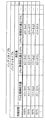
- FIG. 5A is a data structure diagram of the first corresponding table according to the embodiment.
- FIG. 5B is a data structure diagram of the second corresponding table according to the embodiment.
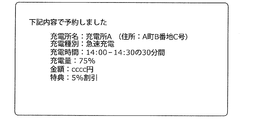
- FIG. 6A is a schematic diagram showing an example of a charging plan according to the embodiment.
- FIG. 6B is a schematic diagram showing an example of a charging plan according to the embodiment.
- FIG. 6C is a schematic diagram showing an example of the charging plan according to the embodiment.
- FIG. 7 is a sequence diagram of the charging plan determination process according to the embodiment.
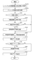
- FIG. 8 is a flowchart of the operation performed by the charging plan determination server according to
- the charging time zone of the battery is determined according to the type of battery. Thereby, the deterioration of the battery can be suppressed to a certain extent.
- its effect is limited.
- the inventor has earnestly studied a method of determining a charging plan that can more effectively suppress deterioration of the battery than ever before. Then, the inventor determines the charging plan in consideration of not only the static state of the battery such as the type of the battery but also the dynamic state of the battery such as the charging state and the deterioration state of the battery, so that the effect is more effective than before. It was found that the deterioration of the battery can be suppressed. As a result, the inventor has come up with the following information processing method and information processing system.
- a computer acquires a charging state and a deterioration state of a battery, determines an upper limit of the charging state of the battery based on the deterioration state, and determines the charging state.
- the charging plan of the battery is determined based on the upper limit of the above and the charging state, and the determined charging plan is output.
- the battery charging plan determined in consideration of the battery dynamic state such as the battery charging state and the deterioration state, which is not considered in the conventional technology is output. Therefore, according to the above information processing method, deterioration of the battery can be suppressed more effectively than before.
- a lower limit of the state of charge of the battery is determined based on the deterioration state, and the charging plan is determined based on the lower limit and the usage schedule. Good. If the charge state of the battery becomes too low, the degree of progress of deterioration of the battery becomes high. On the other hand, according to this configuration, since the charging plan is determined based on the planned use of the battery and the lower limit of the state of charge of the battery, the state of charge of the battery falls below the lower limit after use of the battery, and deterioration is promoted. It can be suppressed.
- the position of a vehicle equipped with the battery and the positions of a plurality of charging stations are acquired, and based on the positions of the vehicle and the positions of the plurality of charging stations, the information including the charging location is included. You may decide on a charging plan.
- the charging station to be charged is determined according to the current charging state and the distance from the current location of the vehicle equipped with the battery to the charging station, so that the charging station may be out of power before reaching the charging station. It is possible to prevent the state of charge from becoming too low and accelerating deterioration by the time the battery reaches.
- the charging plan including the information indicating the charging time is determined based on the position of the vehicle and the position of the charging station. You may. As a result, the charging time is determined according to the current charging state and the distance to the charging station, so that charging can be performed before the power is cut off or before the charging state becomes too low.
- information indicating the charging location is obtained based on the moving route of the vehicle equipped with the battery and the positions of the plurality of charging stations, and based on each of the distances from the moving route to each of the plurality of charging stations.
- the charging plan including may be determined.
- the charging station to be charged is determined according to the current charging state and the distance from the travel route to the charging station, so that the charging station may run out before reaching the charging station or before reaching the charging station. It is possible to prevent the state of charge from becoming too low and deterioration being promoted.
- the charging plan may include information indicating an upper limit of the charging state.
- the user or the charger control system can grasp the upper limit of the charge state of the battery and can control the charger so that the charge state does not exceed the upper limit.
- the charging plan may include information indicating the charging time.
- the user or the charger control system can charge the battery so as not to exceed the upper limit of the charging state without referring to the charging state of the battery.
- the reservation status of the charging station may be acquired from the reservation server, the charging plan may be determined based on the reservation status, and the determined charging plan may be output to the reservation server as a reservation request. This makes it possible to automatically reserve a charger with a charging plan that suppresses battery deterioration.
- determining the upper limit of the state of charge may be determining the upper limit of the state of charge based on the degree of deterioration progress according to the degree of the deterioration state.
- the degree of deterioration progress changes depending on the degree of deterioration of the battery.
- the upper limit of the state of charge may be determined based on As a result, it is possible to control the balance between suppression of deterioration of the battery and usability of the battery.
- determining the upper limit of the state of charge may be determined based on at least one of the deterioration state, the amount of current in charging the battery, the amount of current in discharging, the temperature, and the state of charge.
- the upper limit of the charging state can be determined based on the parameters related to the deterioration progress of the battery, and the accuracy of the upper limit can be improved. As a result, it is possible to achieve both suppression of battery deterioration and battery utilization efficiency.
- An information processing system includes an acquisition unit that acquires a charge state and a deterioration state of a battery, a first determination unit that determines an upper limit of the charge state of the battery based on the deterioration state, and a determination unit.
- a second determination unit that determines a charging plan of the battery based on the determined upper limit of the charging state and the charging state; and an output unit that outputs the determined charging plan.
- the battery charging plan determined in consideration of the battery dynamic state such as the battery charging state and the deterioration state, which is not considered in the conventional technology, is output. Therefore, according to the information processing system, deterioration of the battery can be suppressed more effectively than before.
- a recording medium such as a system, a method, an integrated circuit, a computer program, or a computer-readable CD-ROM, and the system, the method, the integrated circuit, the computer. It may be realized by any combination of the program and the recording medium.
- Embodiment 1 Information processing system configuration
- This information processing system determines a charging plan for a battery mounted on a vehicle based on the charging state and the deterioration state of the battery.
- FIG. 1 is a block diagram showing the configuration of the information processing system 1 according to the first embodiment.
- the information processing system 1 includes a charging plan determination server 100, a reservation server 200, a network 300A, a network 300B, vehicles 400A to 400C, and charging stations 500A to 500C. Composed of.
- vehicles 400A to 400C are also simply referred to as vehicle 400
- charging stations 500A to 500C are also simply referred to as charging station 500.
- the vehicle 400 is equipped with a battery and runs by using the electric power of the mounted battery.
- the vehicle 400 acquires the charge state and the deterioration state of the installed battery.
- the state of charge of the battery may be, for example, the current charge rate when the full charge is 100%.
- the deterioration state of the battery may be, for example, a deterioration rate at the present time when the deterioration state is 100% until new charging cannot be performed.
- the vehicle 400 may acquire the cumulative mileage of the mounted battery and estimate the deterioration state of the battery from the acquired cumulative mileage.
- vehicle 400 may acquire the amount of current during charging of the battery mounted therein and estimate the deterioration state of the battery from the acquired amount of current during charging.
- vehicle 400 may acquire the amount of current when the installed battery is discharged (when vehicle 400 is running), and may estimate the deterioration state of the battery from the acquired amount of current when discharged. Further, vehicle 400 may estimate the deterioration state from the elapsed time after the battery is manufactured or after the charging is completed. Vehicle 400 may also estimate the deterioration state of the battery from these combinations. Alternatively, the vehicle 400 may be equipped with, for example, a deterioration state measuring device capable of measuring the deterioration state of the battery, and acquire the deterioration state of the battery by using the deterioration state measuring device installed therein.
- the vehicle 400 includes an input device that receives an operation from a user who uses the vehicle 400, and an output device that outputs information to the user.
- the input device may be, for example, a touch pad, a keyboard, or the like.
- the output device may be, for example, a display, a speaker, or the like.
- the user can input the usage schedule of the battery mounted on the vehicle 400 and the movement route of the vehicle 400 by using the input device.
- the battery usage schedule is an element that affects the battery consumption speed (in other words, the power consumption per unit time) such as the planned or assumed traveling route, mileage, load capacity, speed, acceleration, and the like.
- the usage schedule of the battery may be the travel schedule of the vehicle 400.
- the vehicle 400 acquires the position of its own vehicle.
- the vehicle 400 may acquire the position of the vehicle using GPS, for example.
- Vehicle 400 is communicatively connected to charging plan determination server 100 via network 300A.
- the charging station 500 is a charging station that charges the battery mounted on the vehicle 400.
- the charging station 500 may be capable of charging the battery by, for example, a plurality of charging types (also referred to as charging modes; for example, a normal charging method, a quick charging method, etc.).
- the charging station 500 includes an input device that receives an operation from the administrator of the charging station 500 and an output device that outputs information to the administrator.
- the input device may be, for example, a touch pad, a keyboard, or the like.
- the output device may be, for example, a display, a speaker, or the like.
- charging station 500 includes a touch pad as an input device and a display as an output device.
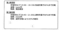
- the administrator can use the input device to input a reservation for using the charging station 500 and a privilege to be provided to a user who uses the charging station 500.
- the privilege may be, for example, the content of giving a 5% discount to the normal charge to the user who has used it in a predetermined time zone (for example, a quiet period). Further, the privilege may be a content of presenting a crude product to a user who has made a reservation in advance and used it. In addition, the privilege may include a 20% discount from the normal charge for a user who uses the normal charge without using the quick charge.
- the charging station 500 is communicably connected to the reservation server 200 via the network 300B.
- the reservation server 200 is communicably connected to a plurality of charging stations 500 via the network 300B, and acquires and manages the reservation status, benefits, and location of the charging stations 500 from each charging station 500.
- the reservation server 200 is further connected to the charging plan determination server 100 so as to be able to communicate.
- the charging plan determination server 100 is communicably connected to a plurality of vehicles 400 via the network 300A, and determines a charging plan of a battery mounted on the vehicle 400 from each vehicle 400.
- the charging plan determination server 100 is further connected to the reservation server 200 so as to be able to communicate.
- the charging plan determination server 100 and the reservation server 200 may be realized by, for example, a computer including a processor and a memory.
- each component of the charging plan determination server 100 and the reservation server 200 may be realized, for example, by the processor executing one or more programs stored in the memory.
- the charging plan determination server 100 and the reservation server 200 may be realized, for example, by a plurality of computers, each including a processor and a memory, communicable with each other operating in cooperation with each other.
- any one or more processors execute one or more programs stored in any one or more memories. It may be realized by Here, it is assumed that charging plan determination server 100 and reservation server 200 are realized by a computer including a processor and a memory.
- the functions of the charging plan determination server and the reservation server may be realized by the same server.
- FIG. 2 is a block diagram showing the configuration of the charging plan determination server 100.
- the charging plan determination server 100 includes a status acquisition unit 11, a usage schedule acquisition unit 12, a position acquisition unit 13, a charging station information acquisition unit 14, a status update confirmation unit 20, and The lower limit determination unit 30, the charging plan determination unit 40, the output unit 51, and the reservation request unit 52 are included.
- the state acquisition unit 11 acquires, from each vehicle 400, a charge state and a deterioration state of a battery mounted on the vehicle 400. Then, the acquired charge state and deterioration state of the battery are stored in association with the information that specifies the vehicle 400 that is the acquisition source. For example, each vehicle 400 regularly transmits the charge state and the deterioration state of the battery to the charging plan determination server 100, and the state acquisition unit 11 periodically transmits the battery charge from each vehicle 400.
- the charge state and the deterioration state of the battery may be acquired by receiving the state and the deterioration state.
- the state acquisition unit 11 transmits a transmission request of the battery charge state and the deteriorated state to each vehicle 400, and the battery charge state and the deteriorated state are transmitted from each vehicle 400 in response to the transmission request.
- the charged state and the deteriorated state of the battery may be acquired.
- the state acquisition unit 11 may further acquire other information regarding the state of the battery from each vehicle 400. Other information may be, for example, the cumulative traveling distance of the mounted battery, the amount of current when the mounted battery is charged, the amount of current when the mounted battery is discharged, the temperature of the mounted battery, or the like. Good.
- the usage schedule acquisition unit 12 acquires, from each vehicle 400, a usage schedule of a battery mounted on the vehicle 400. Then, the acquired usage schedule of the battery is stored in association with the information that specifies the vehicle 400 that is the acquisition source.
- FIG. 3 shows an example of a battery usage schedule acquired by the usage schedule acquisition unit 12. For example, when each vehicle 400 inputs a battery usage schedule from a user who uses the vehicle 400, each vehicle 400 transmits the input battery usage schedule to the charging plan determination server 100, and the usage schedule acquisition unit 12 receives each.
- the usage schedule of the battery may be acquired by receiving the usage schedule of the battery transmitted from vehicle 400.
- the state acquisition unit 11 transmits a transmission request for the battery usage schedule to each vehicle 400, and receives the battery usage schedule transmitted from each vehicle 400 in response to the transmission request to receive the battery. You may get the usage schedule of.
- the usage schedule acquisition unit 12 does not have to acquire the battery usage schedule from the vehicle 400 in which the battery usage schedule has not been input.
- the position acquisition unit 13 acquires the position of the vehicle 400 from each vehicle 400. Then, the acquired position of the vehicle 400 is stored in association with the information that specifies the acquisition source vehicle 400. For example, each vehicle 400 regularly transmits the position of the vehicle 400 to the charging plan determination server 100, and the position acquisition unit 13 receives the position of the vehicle 400 periodically transmitted from each vehicle 400. Thus, the charge state and the deterioration state of the battery may be acquired. Further, for example, the position acquisition unit 13 transmits a transmission request for the position of the vehicle 400 to each vehicle 400, and receives the position of the vehicle 400 transmitted from each vehicle 400 in response to the transmission request. The position of 400 may be acquired. The state acquisition unit 11 may further acquire a movement route from each vehicle 400. In this case, the state acquisition unit 11 does not have to acquire the travel route from the vehicle 400 to which the travel route has not been input.
- the charging station information acquisition unit 14 acquires the reservation status, benefits, and location of each charging station 500 from the reservation server 200. Then, the acquired reservation status, privilege and position are stored.
- FIG. 4 shows an example of the reservation status acquired by the charging station information acquisition unit 14.
- the charging station information acquisition unit 14 transmits a transmission request for the reservation status, benefits, and location of each charging station 500 to the reservation server 200, and each charging station is transmitted from the reservation server 200 in response to the transmission request.
- the reservation status, privilege, and position of 500 may be acquired.
- the reservation server 200 periodically transmits the reservation status, benefits, and positions of each charging station 500 to the charging plan determination server 100
- the charging station information acquisition unit 14 periodically transmits the reservation status, benefits, and positions from the reservation server 200.
- the reservation status, the privilege, and the position of each charging station 500 may be acquired by receiving the reservation status, the privilege, and the position of each charging station 500 transmitted to each of the charging stations 500.
- the state update confirmation unit 20 when the state acquisition unit 11 newly acquires the deteriorated state of the battery mounted on the vehicle 400 from each vehicle 400, the deteriorated state of the newly acquired battery is the battery acquired last time. Check whether it has been updated from the deterioration state of.
- being updated means that the deterioration state of the newly acquired battery has changed by a predetermined amount or more from the deterioration state of the battery acquired last time.
- the upper / lower limit determination unit 30 determines the battery.
- the upper limit of the state of charge of the battery mounted on the specific vehicle 400 is determined based on the deterioration state of. More specifically, the upper and lower limit determination unit 30 determines, for each battery type, the state of charge of the battery (that is, the remaining amount of the battery), the deterioration state of the battery (that is, the cumulative deterioration amount of the battery), and the deterioration amount.
- the amount of deterioration newly generated in the battery by newly charging the battery is stored in the first correspondence table, and the updated correspondence of the updated battery is stored.
- the upper limit of the charged state of the battery is determined based on the deteriorated state, the first correspondence table to be stored, and the predetermined allowable deterioration amount.
- FIG. 5A is a data configuration diagram of the first correspondence table stored in the upper/lower limit determination unit 30.
- the upper / lower limit determination unit 30 refers to the first correspondence table and refers to the deterioration amount (here, a1, a2, a3, b1, b2) associated with the updated battery deterioration state (here, the cumulative deterioration amount). , B3, etc.), identify one of the deterioration amounts that does not exceed the predetermined allowable deterioration amount, and determine the charge state associated with the specified deterioration amount as the upper limit of the charge state of the battery. To do.
- the first correspondence table is created, for example, using the data acquired by conducting an experiment in advance.
- the table for determining the upper limit of the state of charge may be determined based on the variable factor.
- the deterioration state that is, the cumulative deterioration amount is input
- a table corresponding to the input cumulative deterioration amount is determined based on a basic table showing the relationship between the cumulative deterioration amount and the upper limit of the charge state.
- the variable factors include the amount of current flowing in charging, the amount of current flowing in discharging, the temperature of the battery, and the state of charge.
- the table may be determined in consideration of the change in the state of charge.
- the table determination processing based on the variation factor may be performed.
- the upper and lower limit determination unit 30 displays the acquired other information. May also be used to determine the upper limit of the state of charge of the battery.
- the upper / lower limit determination unit 30 provides a second correspondence table showing the correspondence between the charging state, the deterioration state of the battery, the deterioration amount, and the correction amount of the deterioration amount based on other information for each type of battery.
- the upper limit of the battery charge state is determined based on the stored and updated deterioration state of the battery, other information, the second corresponding table to be stored, and the predetermined allowable deterioration amount.
- FIG. 5B is a data configuration diagram of the second correspondence table stored in the upper/lower limit determination unit 30.
- the correction amount (here, ⁇ e1, ⁇ e2, ⁇ e3, ⁇ f1, ⁇ f2, ⁇ f3, etc.) becomes larger as the amount of current increases.
- the correction amount is a positive value that increases as the amount of current increases.
- the other information is the temperature of the battery, the correction amount can be a positive value or a negative value depending on the temperature.
- the upper / lower limit determination unit 30 refers to the second correspondence table, and from the sum of the deterioration amount and the correction amount associated with the updated battery deterioration state, the deterioration does not exceed the predetermined allowable deterioration amount. One of the sums of the amount and the correction amount is specified, and the charge state associated with the specified sum of the deterioration amount and the correction amount is determined as the upper limit of the charge state of the battery.
- the second correspondence table is created, for example, using the data acquired by conducting an experiment in advance.
- the upper / lower limit determination unit 30 may further determine the lower limit of the battery charge state of the specific vehicle 400 based on the updated battery deterioration state. More specifically, the upper and lower limit determination unit 30 stores a third correspondence table that associates the deterioration state of the battery with the lower limit of the charging state of the battery for each battery type, and updates the deterioration of the battery. The lower limit of the state of charge of the battery may be determined based on the state and the stored third correspondence table.
- the upper and lower limit determination unit 30 further updates the deteriorated state of the battery, When the battery is scheduled to be used, the charge state of the battery after the scheduled use of the battery is estimated, and the estimated state of charge of the battery after the planned use of the battery does not fall below the lower limit of the state of charge of the battery during charging.
- the lower limit of the state of charge of the battery may be determined.
- the charge plan determination unit 40 acquires the determined upper limit of the charge state and the state acquisition unit 11. Based on the state of charge of the specific vehicle 400, a battery charging plan showing the charging details for suppressing the deterioration of the battery is determined.
- the upper and lower limit determination units 30 determine the lower limit of the charging state of the battery mounted on the specific vehicle 400, and the usage schedule acquisition unit 12 determines the usage schedule of the battery mounted on the specific vehicle 400. If so, the battery charging plan may be determined based on the lower limit of the charging state of those batteries and the usage schedule of the batteries.
- the charging plan determination unit 40 when the position acquisition unit 13 acquires the position of the specific vehicle 400 and the charging station information acquisition unit 14 acquires the positions of the plurality of charging stations 500, the specific vehicle 400
- the charging plan of the battery including the information indicating the charging location may be determined based on the position of the charging station 500 and the positions of the plurality of charging stations 500.
- the charging plan determination unit 40 may determine, for example, a predetermined number of charging stations 500 as charging locations in the order of closest or closest to the position of the specific vehicle 400.
- the charging plan determination unit 40 may determine the charging fee to be the lowest or a predetermined number of charging stations 500 in the ascending order as charging locations.
- the charging plan determination unit 40 may determine the charging station 500 as the charging location by combining these plural elements.
- a battery charging plan may be determined that includes information indicating the charging location.
- the charging plan determination unit 40 may determine, for example, a predetermined number of charging stations 500 that are closest to or in the order of being closer to the traveling route of the specific vehicle 400 as charging locations.
- the charging plan determination unit 40 when the position acquisition unit 13 acquires the position of the specific vehicle 400 and the charging station information acquisition unit 14 acquires the position of one charging station 500, the specific vehicle 400
- the charging plan of the battery including the information indicating the charging time may be determined based on the position of and the position of one charging station 500.
- the charging time may be any one of the charging start time, the charging end time, and / or the time required for charging, or a combination thereof.
- the charging plan determination unit 40 may determine the charging start time by estimating the moving time from the position of the specific vehicle 400 to the position of the one charging station 500, or may determine the charging start time.
- the time required for charging or the charging end time may be determined from the charging ability.
- the charging plan determination unit 40 determines the battery charging plan including the information indicating the charging place based on the privilege. You may decide. In this case, the charging plan determination unit 40 may determine, as a charging location, a predetermined number of charging stations 500 in the descending order of the profit received by the user who uses the specific vehicle 400, or in the descending order, for example, depending on the privilege.
- the charging plan determination unit 40 charges the battery including the information indicating the charging location based on the reservation statuses. You may decide the plan. In this case, the charging plan determination unit 40 may determine the charging plan at the plurality of charging stations 500 so that charging is not performed during the reserved time period indicated by the reservation status, or each charging estimated from the reservation status. From the operating rate of the charging station 500, the charging plan may be determined so that the operating rate of the specific charging station 500 does not become too high or the operating rate of the specific charging station 500 does not become too low.
- the reservation requesting unit 52 transmits (that is, outputs) the determined charging plan as a reservation request to the reservation server 200.
- the reservation request unit 52 transmits the reservation request to the reservation server 200 and the reservation server 200 sends a response to the reservation request, the reservation request unit 52 receives the response.
- the output unit 51 transmits (ie, outputs) the determined charging plan to the specific vehicle 400 when the charging plan determination unit 40 determines the charging plan for the specific vehicle 400.
- 6A, 6B, and 6C are schematic views showing an example of a charging plan output by the output unit 51, respectively.
- the charging plan illustrated in FIG. 6A includes a charging station name (charging location), a charging start time (charging time), a charging end time (charging time), a charging type (charging mode), and an upper limit of the charging state.
- the reservation request unit 52 transmits the charging plan as a reservation request to the reservation server 200, and the reservation request unit 52 receives a positive response returned from the reservation server 200.
- the charging plan output from the output unit 51 it is an example of the charging plan output from the output unit 51.
- the charging plan illustrated in FIG. 6C is an example of a charging plan including only the upper limit of the charging state.
- the output unit 51 transmits, for example, to the vehicle 400 registered in advance in the charging plan determination server 100, a charging plan including only the upper limit of the charging state (for example, the charging plan illustrated in FIG. 6C), and the like.
- a charging plan (for example, the charging plan illustrated in FIG. 6A) including other information in addition to the upper limit of the charging state may be transmitted to the vehicle 400 of FIG.
- the information processing system 1 having the above configuration performs a charging plan determination process that determines the charging plan of the vehicle 400.
- FIG. 7 is a sequence diagram of charging plan determination processing.
- FIG. 8 is a flowchart of the operation performed by the charging plan determination server 100 in the charging plan determination process.
- the vehicle 400 acquires the charging status and the deterioration status of the installed battery, and transmits the acquired charging status and the deterioration status of the battery to the charging plan determination server 100 (step S10).
- the vehicle 400 has acquired other information related to the state of the battery to be installed, in addition to transmitting the charging state and the deterioration state of the battery, other information related to the state of the battery is also displayed. It may be transmitted to the charging plan determination server 100.
- the state acquisition unit 11 acquires the charged state and the deteriorated state of the transmitted battery by receiving the transmitted state (step S10a). At this time, when other information related to the battery state is transmitted from the vehicle 400, the state acquisition unit 11 acquires the other information related to the battery state transmitted.
- Vehicle 400 further transmits to the charging plan determination server 100 the usage schedule of the installed battery, which is input by the user who uses the vehicle 400 (step S20).
- vehicle 400 may not transmit the battery usage schedule.
- the usage schedule acquisition unit 12 acquires the battery usage schedule by receiving the transmitted battery usage schedule (step S20a).
- the state update confirmation unit 20 confirms whether the newly acquired deteriorated state of the battery is updated from the previously acquired deteriorated state of the battery (step). S30).
- step S30 when it is confirmed that the deterioration state of the battery is updated (step S30: Yes), the upper/lower limit determination unit 30 sets the upper limit of the charging state of the battery based on the deterioration state of the battery. It is determined (step S40). At this time, when the state acquisition unit 11 receives other information related to the battery state from the vehicle 400, the upper and lower limit determination unit 30 determines the battery based on the other information related to the battery state. The upper limit of the state of charge may be determined.
- the upper/lower limit determination unit 30 confirms whether the usage schedule acquisition unit 12 has acquired the usage schedule of the battery (step S45).
- step S45 when it is confirmed that the usage schedule of the battery is acquired (step S45: Yes), the upper/lower limit determination unit 30 determines, based on the deterioration state of the battery and the usage schedule of the battery. The lower limit of the state of charge of the battery is determined (step S50).
- step S50 ends, or when it is confirmed that the deterioration state of the battery is not updated in the process of step S30 (step S30: No), the usage schedule of the battery is acquired in the process of step S45.
- the charging station information acquisition unit 14 transmits a request for transmitting the reservation status of each charging station 500 to the reservation server 200 (step S60).
- the lower limit determination unit 30 determines the state of charge of the battery based on the deterioration state of the battery. The lower limit of may be determined (step S50).
- the reservation server 200 When the reservation status transmission request is transmitted to the reservation server 200, the reservation server 200 receives the reservation status transmission request. Then, the reservation server 200 transmits the reservation status of each charging station 500 as a response to the transmission request of the reservation status (step S65). At this time, the reservation server 200 may transmit the privilege and the position of each charging station 500 in addition to the reservation status of each charging station 500.
- the charging station information acquisition unit 14 acquires by receiving the transmitted reservation status of each charging station 500. At this time, when the privilege and position of each charging station 500 are transmitted from the reservation server 200, the charging station information acquisition unit 14 receives the transmitted privilege and position of each charging station 500. get.
- the charging plan determination unit 40 determines the upper limit of the battery charge state determined by the upper / lower limit determination unit 30 and the charge state of the battery acquired by the state acquisition unit 11.
- the charging plan of the battery is determined based on the reservation status of each charging station 500 acquired by the charging station information acquisition unit 14 (step S70).
- the charging plan determination unit 40 has the privilege of each charging station 500 by the charging station information acquisition unit 14.
- the charging plan of the battery is also based on the position of the vehicle 400, the traveling route of the vehicle 400, the privilege of each charging station 500, and/or the position of each charging station 500.
- the charging plan determination unit 40 determines whether the battery determined by the upper/lower limit determination unit 30 is based on the reservation status of each charging station 500 regardless of whether the reservation status of each charging station 500 is acquired.
- the charging plan of the battery may be determined based on the upper limit of the charging state and the charging state of the battery acquired by the status acquisition unit 11 (step S70).
- the reservation requesting unit 52 checks whether the target vehicle 400 is a vehicle with a reservation option (step S75).
- the vehicle with the reservation option is a vehicle that is the target of outputting the determined battery charging plan as a reservation request to the reservation server 200 when the battery charging plan is determined.
- step S75 when the target vehicle 400 is a vehicle with a reservation option (step S75: Yes), the reservation requesting unit 52 reserves the battery charging plan determined by the charging plan determining unit 40. The request is output by transmitting it to the reservation server 200 (step S80). Note that the reservation request unit 52 transmits the charging plan of the battery determined by the charging plan determination unit 40 to the reservation server 200 as a reservation request regardless of whether the target vehicle 400 is a vehicle with a reservation option. (Step S80).
- step S75 when the target vehicle 400 is not a vehicle with a reservation option (step S75: No) and when the process of step S80 is completed, the output unit 51 is determined by the charge plan determination unit 40. The determined charging plan is output by transmitting it to the vehicle 400 (step S90). Then, vehicle 400 receives the transmitted charging plan and outputs the received charging plan using the output device.
- step S90 the information processing system 1 ends the charge plan determination process.
- the battery charging plan determined in consideration of the dynamic state of the battery such as the charging state and the deterioration state of the battery, which is not considered in the conventional technique, is output. Therefore, according to the information processing system 1, the deterioration of the battery can be suppressed more effectively than before.
- the vehicle 400 acquires the deterioration state of the battery mounted therein, and the state acquisition unit 11 receives the deterioration state of the battery transmitted from the vehicle 400. It was an example of a configuration for acquiring the deteriorated state of the battery. However, if the state acquisition unit 11 can acquire the deterioration state of the battery mounted on the vehicle 400, the information processing system 1 is not necessarily limited to the above configuration example. In the information processing system 1, for example, information that allows the vehicle 400 to estimate the deterioration state of the battery (for example, the cumulative mileage by the mounted battery, the amount of current when the mounted battery is charged, and the current when the mounted battery is discharged).
- the configuration may be such that the deteriorated state of the battery mounted on the vehicle 400 is acquired by estimating the deteriorated state of the battery from the possible information.
- the information processing system 1 is an example of a configuration in which the upper / lower limit determination unit 30 determines the upper limit of the state of charge of the battery so as not to exceed a predetermined allowable deterioration amount.
- the upper/lower limit determination unit 30 causes the vehicle 400 equipped with the battery to travel a long distance from the scheduled use of the battery acquired by the usage schedule acquisition unit 12. Only when it is known that it is a schedule, an example of a configuration in which the upper limit of the state of charge of the battery is determined so as to exceed the predetermined allowable deterioration amount may be used.
- the information processing system 1 is a system configured to determine the battery charging plan for the battery mounted on the vehicle 400.
- the information processing system according to the present disclosure may be a system configured to determine a battery charging plan for a battery mounted in a device or the like other than the battery mounted in the vehicle 400.
- the information processing system according to the present disclosure may be a system configured to determine a battery charging plan for a battery mounted on a mobile device represented by a smartphone or the like.
- the information processing system 1 determines a battery charging plan.
- the information processing system 1 may determine the battery replacement plan. Specifically, the information processing system 1 acquires a usage schedule of the battery, determines a lower limit of the charge state of the battery based on the deterioration state of the battery, and based on the determined lower limit, the charge status, and the usage schedule of the battery. And decide on a battery replacement plan. For example, the information processing system 1 searches for a battery that is charged to such an extent that the state of charge after use estimated from the planned use of the battery does not fall below the lower limit, and replaces the found battery with the installed battery. Determine the plan to do. This can save the time required to charge the battery.
- the information processing system 1 determines the upper limit of the state of charge of the battery based on the deterioration state of the battery, and determines the replacement plan of the battery based on the determined upper limit, the state of charge, and the planned use of the battery. Good. For example, the information processing system 1 searches for a battery that is charged to such an extent that the state of charge in use estimated from the usage schedule of the battery does not exceed the upper limit, and replaces the searched battery with the installed battery. Determine the plan to do.
- An example of a case where the charging state during use becomes high is charging by regenerative braking. When the battery is scheduled to be used in a vehicle that is planned to travel on a downhill route, the charge state of the battery may exceed the upper limit. In such a case, it is possible to prevent the battery from deteriorating due to charging by the regenerative brake.
- a part or all of the components included in the information processing system 1 may be composed of one system LSI (Large Scale Integration: large-scale integrated circuit).
- the system LSI is a super-multifunctional LSI manufactured by integrating a plurality of constituent parts on one chip, and specifically, a microprocessor, a ROM (Read Only Memory), a RAM (Random Access Memory), etc. It is a computer system composed of. A computer program is stored in the ROM. The system LSI achieves its function by operating the microprocessor according to the computer program.
- the system LSI is used here, but it may also be called IC, LSI, super LSI, or ultra LSI depending on the degree of integration. Further, the method of circuit integration is not limited to LSI, and it may be realized by a dedicated circuit or a general-purpose processor.
- An FPGA Field Programmable Gate Array
- a reconfigurable processor that can reconfigure the connection and settings of the circuit cells inside the LSI may be used.
- One aspect of the present disclosure is not limited to such an information processing system, and may be an information processing method in which a characteristic configuration unit included in the information processing system has steps. Further, one aspect of the present disclosure may be a computer program that causes a computer to execute each characteristic step included in the information processing method. Further, one aspect of the present disclosure may be a computer-readable non-transitory recording medium in which such a computer program is recorded.
- This disclosure can be widely used as a device for determining a battery charging plan.
Abstract
In this information processing method, a computer acquires the charging state and the degradation state of a battery, determines the upper limit of the charging state of the battery on the basis of the degradation state, determines a charging plan for the battery on the basis of the determined upper limit of the charging state and the charging state, and outputs the determined charging plan.
Description
本開示は、情報処理方法、及び情報処理システムに関する。
The present disclosure relates to an information processing method and an information processing system.
従来、カーシェアリングシステムにおいてシェアされる車両に搭載されるバッテリの劣化を抑制するために、バッテリの種類に応じてバッテリの充電時間帯を決定する技術が知られている(例えば、特許文献1参照)。
Conventionally, in order to suppress deterioration of a battery mounted in a vehicle shared in a car sharing system, a technique of determining a charging time zone of the battery according to the type of the battery is known (for example, see Patent Document 1). ).
従来の技術では、バッテリの劣化の抑制は限定的である。
With the conventional technology, suppression of battery deterioration is limited.
そこで、本開示は、バッテリの劣化を、従来よりも効果的に抑制することができる情報処理方法、情報処理システムを提供することを目的とする。
Therefore, an object of the present disclosure is to provide an information processing method and an information processing system capable of suppressing deterioration of a battery more effectively than before.
本開示の一態様に係る情報処理方法は、コンピュータが、バッテリの充電状態と劣化状態とを取得し、前記劣化状態に基づいて前記バッテリの充電状態の上限を決定し、決定された前記充電状態の上限と前記充電状態とに基づいて前記バッテリの充電プランを決定し、決定された前記充電プランを出力する。
In an information processing method according to an aspect of the present disclosure, a computer acquires a charging state and a deterioration state of a battery, determines an upper limit of the charging state of the battery based on the deterioration state, and determines the charging state. The charging plan of the battery is determined based on the upper limit of the above and the charging state, and the determined charging plan is output.
本開示の一態様に係る情報処理システムは、バッテリの充電状態と劣化状態とを取得する取得部と、前記劣化状態に基づいて前記バッテリの充電状態の上限を決定する第1決定部と、決定された前記充電状態の上限と前記充電状態とに基づいて前記バッテリの充電プランを決定する第2決定部と、決定された前記充電プランを出力する出力部と、を備える。
An information processing system according to an aspect of the present disclosure includes an acquisition unit that acquires a charge state and a deterioration state of a battery, a first determination unit that determines an upper limit of the charge state of the battery based on the deterioration state, and a determination unit. A second determination unit that determines a charging plan of the battery based on the determined upper limit of the charging state and the charging state; and an output unit that outputs the determined charging plan.
本開示の一態様に係る情報処理方法、及び情報処理システムによれば、バッテリの劣化を、従来よりも効果的に抑制することができる。
According to the information processing method and the information processing system according to one aspect of the present disclosure, deterioration of the battery can be suppressed more effectively than before.
(本開示の一態様を得るに至った知見)
上述したように、従来の技術では、バッテリの種類に応じてバッテリの充電時間帯を決定する。これにより、一定程度バッテリの劣化を抑制することができる。しかしながら、その効果は限定的である。このため、発明者は、従来よりも効果的にバッテリの劣化を抑制することができる充電プランの決定方法について鋭意検討を重ねた。そして、発明者は、バッテリの種類といったバッテリの静的な状態だけでなく、バッテリの充電状態、劣化状態といったバッテリの動的な状態を考慮して充電プランを決定することで、従来よりも効果的にバッテリの劣化を抑制できることを見出した。その結果、発明者は、下記情報処理方法、及び情報処理システムに想到した。 (Knowledge leading to one embodiment of the present disclosure)
As described above, in the conventional technique, the charging time zone of the battery is determined according to the type of battery. Thereby, the deterioration of the battery can be suppressed to a certain extent. However, its effect is limited. For this reason, the inventor has earnestly studied a method of determining a charging plan that can more effectively suppress deterioration of the battery than ever before. Then, the inventor determines the charging plan in consideration of not only the static state of the battery such as the type of the battery but also the dynamic state of the battery such as the charging state and the deterioration state of the battery, so that the effect is more effective than before. It was found that the deterioration of the battery can be suppressed. As a result, the inventor has come up with the following information processing method and information processing system.
本開示の一態様に係る情報処理方法は、コンピュータが、バッテリの充電状態と劣化状態とを取得し、前記劣化状態に基づいて前記バッテリの充電状態の上限を決定し、決定された前記充電状態の上限と前記充電状態とに基づいて前記バッテリの充電プランを決定し、決定された前記充電プランを出力する。
In an information processing method according to an aspect of the present disclosure, a computer acquires a charging state and a deterioration state of a battery, determines an upper limit of the charging state of the battery based on the deterioration state, and determines the charging state. The charging plan of the battery is determined based on the upper limit of the above and the charging state, and the determined charging plan is output.
上記情報処理方法によると、従来の技術では考慮されない、バッテリの充電状態、劣化状態といったバッテリの動的な状態を考慮して決定されたバッテリの充電プランが出力される。従って、上記情報処理方法によると、バッテリの劣化を、従来よりも効果的に抑制することができる。
According to the above information processing method, the battery charging plan determined in consideration of the battery dynamic state such as the battery charging state and the deterioration state, which is not considered in the conventional technology, is output. Therefore, according to the above information processing method, deterioration of the battery can be suppressed more effectively than before.
また、さらに、前記バッテリの使用予定を取得し、前記劣化状態に基づいて前記バッテリの充電状態の下限を決定し、前記下限と前記使用予定とにも基づいて、前記充電プランを決定するとしてもよい。バッテリの充電状態が低くなりすぎるとバッテリの劣化進行の程度が高くなる。これに対し、本構成によれば、バッテリの使用予定とバッテリの充電状態の下限とに基づいて充電プランが決定されるため、バッテリの使用後にバッテリの充電状態が下限を下回り劣化が促進されてしまうことを抑制することができる。
Further, even if a usage schedule of the battery is acquired, a lower limit of the state of charge of the battery is determined based on the deterioration state, and the charging plan is determined based on the lower limit and the usage schedule. Good. If the charge state of the battery becomes too low, the degree of progress of deterioration of the battery becomes high. On the other hand, according to this configuration, since the charging plan is determined based on the planned use of the battery and the lower limit of the state of charge of the battery, the state of charge of the battery falls below the lower limit after use of the battery, and deterioration is promoted. It can be suppressed.
また、さらに、前記バッテリを搭載する車両の位置と複数の充電所の位置とを取得し、前記車両の位置と前記複数の充電所の位置とにも基づいて、充電場所を示す情報を含む前記充電プランを決定するとしてもよい。これにより、現在の充電状態とバッテリを搭載する車両の現在地から充電所までの距離とに応じて充電すべき充電所が決定されるため、充電所に到達する前に電欠したり、充電所に到達するまでに充電状態が低くなりすぎて劣化が促進されたりすることを抑制することができる。
Further, further, the position of a vehicle equipped with the battery and the positions of a plurality of charging stations are acquired, and based on the positions of the vehicle and the positions of the plurality of charging stations, the information including the charging location is included. You may decide on a charging plan. As a result, the charging station to be charged is determined according to the current charging state and the distance from the current location of the vehicle equipped with the battery to the charging station, so that the charging station may be out of power before reaching the charging station. It is possible to prevent the state of charge from becoming too low and accelerating deterioration by the time the battery reaches.
また、さらに、前記バッテリを搭載する車両の位置と充電所の位置とを取得し、前記車両の位置と前記充電所の位置とにも基づいて、充電時間を示す情報を含む前記充電プランを決定するとしてもよい。これにより、現在の充電状態と充電所までの距離に応じて充電時間が決定されるため、電欠する前に充電したり、充電状態が低くなりすぎる前に充電したりすることができる。
Further, the position of the vehicle on which the battery is mounted and the position of the charging station are acquired, and the charging plan including the information indicating the charging time is determined based on the position of the vehicle and the position of the charging station. You may. As a result, the charging time is determined according to the current charging state and the distance to the charging station, so that charging can be performed before the power is cut off or before the charging state becomes too low.
また、さらに、前記バッテリを搭載する車両の移動ルートと複数の充電所の位置とを取得し、前記移動ルートから前記複数の充電所のそれぞれまでの距離それぞれにも基づいて、充電場所を示す情報を含む前記充電プランを決定するとしてもよい。これにより、現在の充電状態と移動ルートから充電所までの距離とに応じて充電すべき充電所が決定されるため、充電所に到達する前に電欠したり、充電所に到達するまでに充電状態が低くなりすぎて劣化が促進されたりすることを抑制することができる。
Further, information indicating the charging location is obtained based on the moving route of the vehicle equipped with the battery and the positions of the plurality of charging stations, and based on each of the distances from the moving route to each of the plurality of charging stations. The charging plan including may be determined. As a result, the charging station to be charged is determined according to the current charging state and the distance from the travel route to the charging station, so that the charging station may run out before reaching the charging station or before reaching the charging station. It is possible to prevent the state of charge from becoming too low and deterioration being promoted.
また、前記充電プランは、前記充電状態の上限を示す情報を含むとしてもよい。これにより、ユーザ又は充電器制御システムは、バッテリの充電状態の上限を把握することができ、充電状態が上限を超えないように充電器を制御することができる。
Also, the charging plan may include information indicating an upper limit of the charging state. Thereby, the user or the charger control system can grasp the upper limit of the charge state of the battery and can control the charger so that the charge state does not exceed the upper limit.
また、前記充電プランは、充電時間を示す情報を含むとしてもよい。これにより、ユーザ又は充電器制御システムは、バッテリの充電状態を参照することなく充電状態の上限を超えないように充電することができる。
Further, the charging plan may include information indicating the charging time. Thereby, the user or the charger control system can charge the battery so as not to exceed the upper limit of the charging state without referring to the charging state of the battery.
また、さらに、充電所の予約状況を予約サーバから取得し、前記予約状況にも基づいて前記充電プランを決定し、決定された前記充電プランを予約要求として前記予約サーバに出力するとしてもよい。これにより、バッテリの劣化が抑制される充電プランで充電器を自動的に予約することができる。
Furthermore, the reservation status of the charging station may be acquired from the reservation server, the charging plan may be determined based on the reservation status, and the determined charging plan may be output to the reservation server as a reservation request. This makes it possible to automatically reserve a charger with a charging plan that suppresses battery deterioration.
また、前記充電状態の上限を決定することは、前記劣化状態の程度に応じた劣化進行の程度に基づいて前記充電状態の上限を決定することであるとしてもよい。バッテリの劣化状態の程度によって劣化進行の程度が変化する。これに対し、本構成によれば、バッテリの劣化進行を抑制することができる充電状態の上限を決定することができる。
Further, determining the upper limit of the state of charge may be determining the upper limit of the state of charge based on the degree of deterioration progress according to the degree of the deterioration state. The degree of deterioration progress changes depending on the degree of deterioration of the battery. On the other hand, according to this configuration, it is possible to determine the upper limit of the state of charge that can suppress the progress of deterioration of the battery.
また、さらに、許容される劣化進行の程度を取得し、前記充電状態の上限を決定することは、前記劣化状態の程度に応じた劣化進行の程度と、前記許容される劣化進行の程度と、に基づいて前記充電状態の上限を決定することであるとしてもよい。これにより、バッテリの劣化進行の抑制とバッテリの使用性とのバランスをコントロールすることができる。
Further, further, obtaining the degree of deterioration progress allowed, and determining the upper limit of the state of charge, the degree of deterioration progress according to the degree of the deterioration state, the degree of deterioration progress allowed, The upper limit of the state of charge may be determined based on As a result, it is possible to control the balance between suppression of deterioration of the battery and usability of the battery.
また、前記充電状態の上限を決定することは、前記劣化状態と、前記バッテリの充電における電流量、放電における電流量、温度及び前記充電状態の少なくとも1つに基づいて決定されるとしてもよい。これにより、バッテリの劣化進行に関わるパラメタに基づき充電状態の上限を決定することができ、上限の正確性を向上させることができる。その結果、バッテリの劣化の抑制とバッテリの利用効率とを両立させることができる。
Also, determining the upper limit of the state of charge may be determined based on at least one of the deterioration state, the amount of current in charging the battery, the amount of current in discharging, the temperature, and the state of charge. As a result, the upper limit of the charging state can be determined based on the parameters related to the deterioration progress of the battery, and the accuracy of the upper limit can be improved. As a result, it is possible to achieve both suppression of battery deterioration and battery utilization efficiency.
本開示の一態様に係る情報処理システムは、バッテリの充電状態と劣化状態とを取得する取得部と、前記劣化状態に基づいて前記バッテリの充電状態の上限を決定する第1決定部と、決定された前記充電状態の上限と前記充電状態とに基づいて前記バッテリの充電プランを決定する第2決定部と、決定された前記充電プランを出力する出力部と、を備える。
An information processing system according to an aspect of the present disclosure includes an acquisition unit that acquires a charge state and a deterioration state of a battery, a first determination unit that determines an upper limit of the charge state of the battery based on the deterioration state, and a determination unit. A second determination unit that determines a charging plan of the battery based on the determined upper limit of the charging state and the charging state; and an output unit that outputs the determined charging plan.
上記情報処理システムによると、従来の技術では考慮されない、バッテリの充電状態、劣化状態といったバッテリの動的な状態を考慮して決定されたバッテリの充電プランが出力される。従って、上記情報処理システムによると、バッテリの劣化を、従来よりも効果的に抑制することができる。
According to the above information processing system, the battery charging plan determined in consideration of the battery dynamic state such as the battery charging state and the deterioration state, which is not considered in the conventional technology, is output. Therefore, according to the information processing system, deterioration of the battery can be suppressed more effectively than before.
以下、本開示の一態様に係る情報処理方法、及び情報処理システムの具体例について、図面を参照しながら説明する。ここで示す実施の形態は、いずれも本開示の一具体例を示すものである。従って、以下の実施の形態で示される数値、形状、構成要素、構成要素の配置及び接続形態、並びに、ステップ(工程)及びステップの順序等は、一例であって本開示を限定するものではない。以下の実施の形態における構成要素のうち、独立請求項に記載されていない構成要素については、任意に付加可能な構成要素である。また、各図は、模式図であり、必ずしも厳密に図示されたものではない。
Hereinafter, specific examples of the information processing method and the information processing system according to one aspect of the present disclosure will be described with reference to the drawings. Each of the embodiments shown here shows one specific example of the present disclosure. Therefore, the numerical values, shapes, components, arrangement and connection forms of the components, steps (processes), order of steps, etc. shown in the following embodiments are examples and do not limit the present disclosure. .. Among the components in the following embodiments, the components not described in the independent claims are components that can be arbitrarily added. In addition, each drawing is a schematic view and is not necessarily strictly illustrated.
なお、本開示の包括的又は具体的な態様は、システム、方法、集積回路、コンピュータプログラム又はコンピュータ読み取り可能なCD-ROMなどの記録媒体で実現されてもよく、システム、方法、集積回路、コンピュータプログラム及び記録媒体の任意な組み合わせで実現されてもよい。
Note that the comprehensive or specific aspects of the present disclosure may be realized by a recording medium such as a system, a method, an integrated circuit, a computer program, or a computer-readable CD-ROM, and the system, the method, the integrated circuit, the computer. It may be realized by any combination of the program and the recording medium.
(実施の形態1)
[1.情報処理システムの構成]
以下、実施の形態に係る情報処理システムについて説明する。この情報処理システムは、車両に搭載されるバッテリの充電状態と劣化状態とに基づいて、そのバッテリの充電プランを決定する。 (Embodiment 1)
[1. Information processing system configuration]
The information processing system according to the embodiment will be described below. This information processing system determines a charging plan for a battery mounted on a vehicle based on the charging state and the deterioration state of the battery.
図1は、実施の形態1に係る情報処理システム1の構成を示すブロック図である。
FIG. 1 is a block diagram showing the configuration of the information processing system 1 according to the first embodiment.
図1に示されるように、情報処理システム1は、充電プラン決定サーバ100と、予約サーバ200と、ネットワーク300Aと、ネットワーク300Bと、車両400A~車両400Cと、充電所500A~充電所500Cを含んで構成される。以下では、車両400A~車両400Cのことを、単に車両400とも称し、充電所500A~充電所500Cのことを、単に充電所500とも称する。
As shown in FIG. 1, the information processing system 1 includes a charging plan determination server 100, a reservation server 200, a network 300A, a network 300B, vehicles 400A to 400C, and charging stations 500A to 500C. Composed of. Hereinafter, vehicles 400A to 400C are also simply referred to as vehicle 400, and charging stations 500A to 500C are also simply referred to as charging station 500.
車両400は、バッテリを搭載し、搭載するバッテリの電力を利用して走行する。車両400は、搭載するバッテリの充電状態と劣化状態とを取得する。ここでは、バッテリの充電状態は、具体的には、例えば、満充電を100%とした場合における現時点の充電率であってよい。バッテリの劣化状態は、具体的には、例えば、新たな充電を行うことができなくなるまで劣化した状態を100%とした場合における現時点の劣化率であってよい。車両400は、例えば、搭載するバッテリによる累積走行距離を取得し、取得した累積走行距離からバッテリの劣化状態を推定してもよい。また、車両400は、搭載するバッテリの充電時の電流量を取得し、取得した充電時の電流量からバッテリの劣化状態を推定してもよい。また、車両400は、搭載するバッテリの放電時(車両400の走行時)の電流量を取得し、取得した放電時の電流量からバッテリの劣化状態を推定してもよい。また、車両400は、バッテリの製造後又は充電完了後からの経過時間から劣化状態を推定してもよい。また、車両400は、これらの組み合わせからバッテリの劣化状態を推定してもよい。または、車両400は、例えば、バッテリの劣化状態を測定することができる劣化状態測定装置を搭載し、搭載する劣化状態測定装置を利用してバッテリの劣化状態を取得してもよい。車両400は、車両400を利用するユーザからの操作を受け付ける入力装置と、ユーザへ情報を出力する出力装置とを備える。入力装置は、例えば、タッチパッド、キーボード等であってよい。出力装置は、例えば、ディスプレイ、スピーカ等であってよい。ここでは、車両400は、入力装置としてタッチパッドを備え、出力装置としてディスプレイを備えるとする。ユーザは、入力装置を利用して、車両400に搭載されるバッテリの使用予定と、車両400の移動ルートとを入力することができる。バッテリの使用予定は、予定又は想定される走行ルート、走行距離、積載量、速度、加速度等といったバッテリの消費速度(言い換えると単位時間当たりの電力消費量)に影響を与える要素である。例えば、バッテリの使用予定は、車両400の走行予定であってよい。車両400は、自車両の位置を取得する。車両400は、例えば、GPSを利用して自車両の位置を取得してよい。車両400は、ネットワーク300Aを介して、充電プラン決定サーバ100と通信可能に接続する。
The vehicle 400 is equipped with a battery and runs by using the electric power of the mounted battery. The vehicle 400 acquires the charge state and the deterioration state of the installed battery. Here, the state of charge of the battery may be, for example, the current charge rate when the full charge is 100%. Specifically, the deterioration state of the battery may be, for example, a deterioration rate at the present time when the deterioration state is 100% until new charging cannot be performed. For example, the vehicle 400 may acquire the cumulative mileage of the mounted battery and estimate the deterioration state of the battery from the acquired cumulative mileage. Further, vehicle 400 may acquire the amount of current during charging of the battery mounted therein and estimate the deterioration state of the battery from the acquired amount of current during charging. Further, vehicle 400 may acquire the amount of current when the installed battery is discharged (when vehicle 400 is running), and may estimate the deterioration state of the battery from the acquired amount of current when discharged. Further, vehicle 400 may estimate the deterioration state from the elapsed time after the battery is manufactured or after the charging is completed. Vehicle 400 may also estimate the deterioration state of the battery from these combinations. Alternatively, the vehicle 400 may be equipped with, for example, a deterioration state measuring device capable of measuring the deterioration state of the battery, and acquire the deterioration state of the battery by using the deterioration state measuring device installed therein. The vehicle 400 includes an input device that receives an operation from a user who uses the vehicle 400, and an output device that outputs information to the user. The input device may be, for example, a touch pad, a keyboard, or the like. The output device may be, for example, a display, a speaker, or the like. Here, it is assumed that the vehicle 400 includes a touch pad as an input device and a display as an output device. The user can input the usage schedule of the battery mounted on the vehicle 400 and the movement route of the vehicle 400 by using the input device. The battery usage schedule is an element that affects the battery consumption speed (in other words, the power consumption per unit time) such as the planned or assumed traveling route, mileage, load capacity, speed, acceleration, and the like. For example, the usage schedule of the battery may be the travel schedule of the vehicle 400. The vehicle 400 acquires the position of its own vehicle. The vehicle 400 may acquire the position of the vehicle using GPS, for example. Vehicle 400 is communicatively connected to charging plan determination server 100 via network 300A.
充電所500は、車両400に搭載されるバッテリを充電する充電所である。充電所500は、例えば、複数の充電種別(充電モードともいう。例えば、通常充電方式、急速充電方式等。)によりバッテリに充電することができてよい。充電所500は、充電所500の管理者からの操作を受け付ける入力装置と、管理者へ情報を出力する出力装置とを備える。入力装置は、例えば、タッチパッド、キーボード等であってよい。出力装置は、例えば、ディスプレイ、スピーカ等であってよい。ここでは、充電所500は、入力装置としてタッチパッドを備え、出力装置としてディスプレイを備えるとする。管理者は、入力装置を利用して、充電所500の利用予約と、充電所500を利用するユーザに対して提供する特典とを入力することができる。特典は、例えば、所定の時間帯(例えば閑散期)に利用したユーザに対して、通常料金より5%割引を行うといった内容であってもよい。また、特典は、予め予約してから利用したユーザに対して、粗品をプレゼントするといった内容であってもよい。また、特典は、急速充電を利用せずに通常充電を利用したユーザに対して、通常料金より20%割引を行うといった内容であってもよい。充電所500は、ネットワーク300Bを介して、予約サーバ200と通信可能に接続する。
The charging station 500 is a charging station that charges the battery mounted on the vehicle 400. The charging station 500 may be capable of charging the battery by, for example, a plurality of charging types (also referred to as charging modes; for example, a normal charging method, a quick charging method, etc.). The charging station 500 includes an input device that receives an operation from the administrator of the charging station 500 and an output device that outputs information to the administrator. The input device may be, for example, a touch pad, a keyboard, or the like. The output device may be, for example, a display, a speaker, or the like. Here, charging station 500 includes a touch pad as an input device and a display as an output device. The administrator can use the input device to input a reservation for using the charging station 500 and a privilege to be provided to a user who uses the charging station 500. The privilege may be, for example, the content of giving a 5% discount to the normal charge to the user who has used it in a predetermined time zone (for example, a quiet period). Further, the privilege may be a content of presenting a crude product to a user who has made a reservation in advance and used it. In addition, the privilege may include a 20% discount from the normal charge for a user who uses the normal charge without using the quick charge. The charging station 500 is communicably connected to the reservation server 200 via the network 300B.
予約サーバ200は、ネットワーク300Bを介して複数の充電所500と通信可能に接続し、各充電所500から、充電所500の予約状況と、特典と、位置とを取得して、管理する。予約サーバ200は、さらに、充電プラン決定サーバ100と通信可能に接続する。
The reservation server 200 is communicably connected to a plurality of charging stations 500 via the network 300B, and acquires and manages the reservation status, benefits, and location of the charging stations 500 from each charging station 500. The reservation server 200 is further connected to the charging plan determination server 100 so as to be able to communicate.
充電プラン決定サーバ100は、ネットワーク300Aを介して複数の車両400と通信可能に接続し、各車両400から、車両400に搭載されるバッテリの充電プランを決定する。充電プラン決定サーバ100は、さらに、予約サーバ200と通信可能に接続する。
The charging plan determination server 100 is communicably connected to a plurality of vehicles 400 via the network 300A, and determines a charging plan of a battery mounted on the vehicle 400 from each vehicle 400. The charging plan determination server 100 is further connected to the reservation server 200 so as to be able to communicate.
充電プラン決定サーバ100と、予約サーバ200とは、例えば、プロセッサとメモリとを含んで構成されるコンピュータによって実現されてよい。この場合、充電プラン決定サーバ100と、予約サーバ200との各構成要素は、例えば、プロセッサがメモリに記憶される1以上のプログラムを実行することで実現されてよい。また、充電プラン決定サーバ100と、予約サーバ200とは、例えば、それぞれがプロセッサとメモリとを含んで構成される、互いに通信可能な複数のコンピュータが協調して動作することによって実現されてよい。この場合、充電プラン決定サーバ100と、予約サーバ200との各構成要素は、例えば、いずれかの1以上のプロセッサが、いずれかの1以上のメモリに記憶される、1以上のプログラムを実行することで実現されてよい。ここでは、充電プラン決定サーバ100と、予約サーバ200とは、プロセッサとメモリとを含んで構成されるコンピュータによって実現されるとする。
The charging plan determination server 100 and the reservation server 200 may be realized by, for example, a computer including a processor and a memory. In this case, each component of the charging plan determination server 100 and the reservation server 200 may be realized, for example, by the processor executing one or more programs stored in the memory. In addition, the charging plan determination server 100 and the reservation server 200 may be realized, for example, by a plurality of computers, each including a processor and a memory, communicable with each other operating in cooperation with each other. In this case, in each component of the charging plan determination server 100 and the reservation server 200, for example, any one or more processors execute one or more programs stored in any one or more memories. It may be realized by Here, it is assumed that charging plan determination server 100 and reservation server 200 are realized by a computer including a processor and a memory.
なお、充電プラン決定サーバと予約サーバの機能は、同一のサーバにて実現されてもよい。
Note that the functions of the charging plan determination server and the reservation server may be realized by the same server.
図2は、充電プラン決定サーバ100の構成を示すブロック図である。
FIG. 2 is a block diagram showing the configuration of the charging plan determination server 100.
図2に示されるように、充電プラン決定サーバ100は、状態取得部11と、使用予定取得部12と、位置取得部13と、充電所情報取得部14と、状態更新確認部20と、上下限決定部30と、充電プラン決定部40と、出力部51と、予約要求部52とを含んで構成される。
As shown in FIG. 2, the charging plan determination server 100 includes a status acquisition unit 11, a usage schedule acquisition unit 12, a position acquisition unit 13, a charging station information acquisition unit 14, a status update confirmation unit 20, and The lower limit determination unit 30, the charging plan determination unit 40, the output unit 51, and the reservation request unit 52 are included.
状態取得部11は、各車両400から、車両400に搭載されるバッテリの充電状態と劣化状態とを取得する。そして、取得したバッテリの充電状態と劣化状態とを、取得元の車両400を特定する情報と紐づけて記憶する。例えば、各車両400は、充電プラン決定サーバ100に、定期的に、バッテリの充電状態と劣化状態とを送信し、状態取得部11は、各車両400から定期的に送信される、バッテリの充電状態と劣化状態とを受信することで、バッテリの充電状態と劣化状態とを取得するとしてもよい。また、例えば、状態取得部11は、各車両400に、バッテリの充電状態と劣化状態との送信要求を送信し、各車両400から送信要求に応じて送信される、バッテリの充電状態と劣化状態とを受信することで、バッテリの充電状態と劣化状態とを取得するとしてもよい。状態取得部11は、各車両400から、さらに、バッテリの状態に係る他の情報を取得してもよい。他の情報としては、例えば、搭載されるバッテリによる累積走行距離、搭載されるバッテリの充電時の電流量、搭載されるバッテリの放電時の電流量、搭載されるバッテリの温度等であってもよい。
The state acquisition unit 11 acquires, from each vehicle 400, a charge state and a deterioration state of a battery mounted on the vehicle 400. Then, the acquired charge state and deterioration state of the battery are stored in association with the information that specifies the vehicle 400 that is the acquisition source. For example, each vehicle 400 regularly transmits the charge state and the deterioration state of the battery to the charging plan determination server 100, and the state acquisition unit 11 periodically transmits the battery charge from each vehicle 400. The charge state and the deterioration state of the battery may be acquired by receiving the state and the deterioration state. Further, for example, the state acquisition unit 11 transmits a transmission request of the battery charge state and the deteriorated state to each vehicle 400, and the battery charge state and the deteriorated state are transmitted from each vehicle 400 in response to the transmission request. By receiving and, the charged state and the deteriorated state of the battery may be acquired. The state acquisition unit 11 may further acquire other information regarding the state of the battery from each vehicle 400. Other information may be, for example, the cumulative traveling distance of the mounted battery, the amount of current when the mounted battery is charged, the amount of current when the mounted battery is discharged, the temperature of the mounted battery, or the like. Good.
使用予定取得部12は、各車両400から、車両400に搭載されるバッテリの使用予定を取得する。そして、取得したバッテリの使用予定を、取得元の車両400を特定する情報と紐づけて記憶する。図3に、使用予定取得部12が取得するバッテリの使用予定の一例を示す。例えば、各車両400は、車両400を利用するユーザから、バッテリの使用予定が入力されると、入力されたバッテリの使用予定を充電プラン決定サーバ100に送信し、使用予定取得部12は、各車両400から送信される、バッテリの使用予定を受信することで、バッテリの使用予定を取得するとしてもよい。また、例えば、状態取得部11は、各車両400に、バッテリの使用予定の送信要求を送信し、各車両400から送信要求に応じて送信される、バッテリの使用予定を受信することで、バッテリの使用予定を取得するとしてもよい。使用予定取得部12は、バッテリの使用予定が入力されていない車両400からは、バッテリの使用予定を取得しなくてもよい。
The usage schedule acquisition unit 12 acquires, from each vehicle 400, a usage schedule of a battery mounted on the vehicle 400. Then, the acquired usage schedule of the battery is stored in association with the information that specifies the vehicle 400 that is the acquisition source. FIG. 3 shows an example of a battery usage schedule acquired by the usage schedule acquisition unit 12. For example, when each vehicle 400 inputs a battery usage schedule from a user who uses the vehicle 400, each vehicle 400 transmits the input battery usage schedule to the charging plan determination server 100, and the usage schedule acquisition unit 12 receives each. The usage schedule of the battery may be acquired by receiving the usage schedule of the battery transmitted from vehicle 400. Further, for example, the state acquisition unit 11 transmits a transmission request for the battery usage schedule to each vehicle 400, and receives the battery usage schedule transmitted from each vehicle 400 in response to the transmission request to receive the battery. You may get the usage schedule of. The usage schedule acquisition unit 12 does not have to acquire the battery usage schedule from the vehicle 400 in which the battery usage schedule has not been input.
位置取得部13は、各車両400から、車両400の位置を取得する。そして、取得した車両400の位置を、取得元の車両400を特定する情報と紐づけて記憶する。例えば、各車両400は、充電プラン決定サーバ100に、定期的に、車両400の位置を送信し、位置取得部13は、各車両400から定期的に送信される、車両400の位置を受信することで、バッテリの充電状態と劣化状態とを取得するとしてもよい。また、例えば、位置取得部13は、各車両400に、車両400の位置の送信要求を送信し、各車両400から送信要求に応じて送信される、車両400の位置を受信することで、車両400の位置を取得するとしてもよい。状態取得部11は、各車両400から、さらに、移動ルートを取得してもよい。この場合、状態取得部11は、移動ルートが入力されていない車両400からは、移動ルートを取得しなくてもよい。
The position acquisition unit 13 acquires the position of the vehicle 400 from each vehicle 400. Then, the acquired position of the vehicle 400 is stored in association with the information that specifies the acquisition source vehicle 400. For example, each vehicle 400 regularly transmits the position of the vehicle 400 to the charging plan determination server 100, and the position acquisition unit 13 receives the position of the vehicle 400 periodically transmitted from each vehicle 400. Thus, the charge state and the deterioration state of the battery may be acquired. Further, for example, the position acquisition unit 13 transmits a transmission request for the position of the vehicle 400 to each vehicle 400, and receives the position of the vehicle 400 transmitted from each vehicle 400 in response to the transmission request. The position of 400 may be acquired. The state acquisition unit 11 may further acquire a movement route from each vehicle 400. In this case, the state acquisition unit 11 does not have to acquire the travel route from the vehicle 400 to which the travel route has not been input.
充電所情報取得部14は、予約サーバ200から、各充電所500の予約状況と特典と位置とを取得する。そして、取得した予約状況と特典と位置とを記憶する。図4に充電所情報取得部14が取得する予約状況の一例を示す。例えば、充電所情報取得部14は、予約サーバ200へ、各充電所500の予約状況と特典と位置との送信要求を送信し、予約サーバ200から送信要求に応じて送信される、各充電所500の予約状況と特典と位置とを受信することで、各充電所500の予約状況と特典と位置とを取得するとしてもよい。また、例えば、予約サーバ200は、充電プラン決定サーバ100へ、定期的に、各充電所500の予約状況と特典と位置とを送信し、充電所情報取得部14は、予約サーバ200から定期的に送信される、各充電所500の予約状況と特典と位置とを受信することで、各充電所500の予約状況と特典と位置とを取得するとしてもよい。
The charging station information acquisition unit 14 acquires the reservation status, benefits, and location of each charging station 500 from the reservation server 200. Then, the acquired reservation status, privilege and position are stored. FIG. 4 shows an example of the reservation status acquired by the charging station information acquisition unit 14. For example, the charging station information acquisition unit 14 transmits a transmission request for the reservation status, benefits, and location of each charging station 500 to the reservation server 200, and each charging station is transmitted from the reservation server 200 in response to the transmission request. By receiving the reservation status, privilege, and position of 500, the reservation status, privilege, and position of each charging station 500 may be acquired. Further, for example, the reservation server 200 periodically transmits the reservation status, benefits, and positions of each charging station 500 to the charging plan determination server 100, and the charging station information acquisition unit 14 periodically transmits the reservation status, benefits, and positions from the reservation server 200. The reservation status, the privilege, and the position of each charging station 500 may be acquired by receiving the reservation status, the privilege, and the position of each charging station 500 transmitted to each of the charging stations 500.
状態更新確認部20は、状態取得部11が、各車両400から、車両400に搭載されるバッテリの劣化状態を新たに取得した場合において、新たに取得したバッテリの劣化状態が、前回取得したバッテリの劣化状態から更新されているか否かを確認する。ここで、更新されているとは、新たに取得したバッテリの劣化状態が、前回取得したバッテリの劣化状態から、所定量以上変動している場合のことをいう。
In the state update confirmation unit 20, when the state acquisition unit 11 newly acquires the deteriorated state of the battery mounted on the vehicle 400 from each vehicle 400, the deteriorated state of the newly acquired battery is the battery acquired last time. Check whether it has been updated from the deterioration state of. Here, being updated means that the deterioration state of the newly acquired battery has changed by a predetermined amount or more from the deterioration state of the battery acquired last time.
上下限決定部30は、状態更新確認部20が、一の車両400(以下、「特定車両400」と称する。)について、バッテリの劣化状態が更新されていることを確認した場合に、そのバッテリの劣化状態に基づいて、その特定車両400に搭載されるバッテリの充電状態の上限を決定する。より具体的には、上下限決定部30は、バッテリのタイプ毎に、バッテリの充電状態(すなわち、バッテリの残量)と、バッテリの劣化状態(すなわち、バッテリの累積劣化量)と、劣化量(すなわち、バッテリに新たに充電することで、そのバッテリに新たに生じる劣化の量であり、言い換えると劣化進行の程度)との対応関係を示す第1対応テーブルを記憶し、更新されたバッテリの劣化状態と、記憶する第1対応テーブルと、予め定められた許容劣化量とに基づいて、バッテリの充電状態の上限を決定する。
When the state update confirmation unit 20 confirms that the deterioration state of the battery of one vehicle 400 (hereinafter referred to as "specific vehicle 400") has been updated, the upper / lower limit determination unit 30 determines the battery. The upper limit of the state of charge of the battery mounted on the specific vehicle 400 is determined based on the deterioration state of. More specifically, the upper and lower limit determination unit 30 determines, for each battery type, the state of charge of the battery (that is, the remaining amount of the battery), the deterioration state of the battery (that is, the cumulative deterioration amount of the battery), and the deterioration amount. (In other words, the amount of deterioration newly generated in the battery by newly charging the battery, in other words, the degree of deterioration progress) is stored in the first correspondence table, and the updated correspondence of the updated battery is stored. The upper limit of the charged state of the battery is determined based on the deteriorated state, the first correspondence table to be stored, and the predetermined allowable deterioration amount.
図5Aは、上下限決定部30が記憶する第1対応テーブルのデータ構成図である。
FIG. 5A is a data configuration diagram of the first correspondence table stored in the upper/lower limit determination unit 30.
上下限決定部30は、第1対応テーブルを参照し、更新されたバッテリの劣化状態(ここでは、累積劣化量)に対応付けられた劣化量(ここでは、a1、a2、a3、b1、b2、b3等)の中から、予め定められた許容劣化量を上回らない劣化量うちの1つを特定し、特定した劣化量に対応付けられた充電状態を、そのバッテリの充電状態の上限として決定する。
The upper / lower limit determination unit 30 refers to the first correspondence table and refers to the deterioration amount (here, a1, a2, a3, b1, b2) associated with the updated battery deterioration state (here, the cumulative deterioration amount). , B3, etc.), identify one of the deterioration amounts that does not exceed the predetermined allowable deterioration amount, and determine the charge state associated with the specified deterioration amount as the upper limit of the charge state of the battery. To do.
第1対応テーブルは、例えば、予め実験を行うことで取得されたデータを用いて作成される。なお、充電状態の上限を決定するためのテーブルは、変動要素に基づき決定されてもよい。例えば、劣化状態すなわち累積劣化量をインプットとして、累積劣化量と充電状態の上限との関係性を示す基本テーブルに基づき、インプットされた累積劣化量に応じたテーブルが決定される。変動要素としては、累積劣化量に加えて、充電において流れる電流量、放電において流れる電流量、バッテリの温度、及び充電状態などがある。変動要素が充電状態である場合は、充電状態の変化を考慮してテーブルが決定されてもよい。なお、図5Bを参照して後述される補正量を用いた充電状態の上限の決定処理の代わりに、変動要素に基づくテーブル決定処理が行われてもよい。
The first correspondence table is created, for example, using the data acquired by conducting an experiment in advance. The table for determining the upper limit of the state of charge may be determined based on the variable factor. For example, the deterioration state, that is, the cumulative deterioration amount is input, and a table corresponding to the input cumulative deterioration amount is determined based on a basic table showing the relationship between the cumulative deterioration amount and the upper limit of the charge state. In addition to the cumulative deterioration amount, the variable factors include the amount of current flowing in charging, the amount of current flowing in discharging, the temperature of the battery, and the state of charge. When the variable element is the state of charge, the table may be determined in consideration of the change in the state of charge. In addition, instead of the determination processing of the upper limit of the state of charge using the correction amount described later with reference to FIG. 5B, the table determination processing based on the variation factor may be performed.
上下限決定部30は、状態取得部11が、特定車両400について、更新された劣化状態と共に、バッテリの状態に係る他の情報を取得している場合には、その取得された他の情報をも用いて、バッテリの充電状態の上限を決定するとしてもよい。この場合、上下限決定部30は、バッテリのタイプ毎に、充電状態と、バッテリの劣化状態と、劣化量と、他の情報による劣化量の補正量との対応関係を示す第2対応テーブルを記憶し、更新されたバッテリの劣化状態と、他の情報と、記憶する第2対応テーブルと、予め定められた許容劣化量とに基づいて、バッテリの充電状態の上限を決定する。
If the state acquisition unit 11 has acquired other information related to the battery state together with the updated deterioration state of the specific vehicle 400, the upper and lower limit determination unit 30 displays the acquired other information. May also be used to determine the upper limit of the state of charge of the battery. In this case, the upper / lower limit determination unit 30 provides a second correspondence table showing the correspondence between the charging state, the deterioration state of the battery, the deterioration amount, and the correction amount of the deterioration amount based on other information for each type of battery. The upper limit of the battery charge state is determined based on the stored and updated deterioration state of the battery, other information, the second corresponding table to be stored, and the predetermined allowable deterioration amount.
図5Bは、上下限決定部30が記憶する第2対応テーブルのデータ構成図である。
FIG. 5B is a data configuration diagram of the second correspondence table stored in the upper/lower limit determination unit 30.
他の情報が、例えば、バッテリの充電時の電流量である場合には、補正量(ここでは、Δe1、Δe2、Δe3、Δf1、Δf2、Δf3等)は、電流量が多いほど値が大きくなる正の値となり、他の情報が、例えば、バッテリの放電時の電流量である場合には、補正量は、電流量が多いほど値が大きくなる正の値となる。一方で、他の情報が、バッテリの温度である場合には、補正量は、その温度に応じて、正の値にもなるし負の値にもなる。
When the other information is, for example, the amount of current when charging the battery, the correction amount (here, Δe1, Δe2, Δe3, Δf1, Δf2, Δf3, etc.) becomes larger as the amount of current increases. When the other information is, for example, the amount of current when the battery is discharged, the correction amount is a positive value that increases as the amount of current increases. On the other hand, when the other information is the temperature of the battery, the correction amount can be a positive value or a negative value depending on the temperature.
上下限決定部30は、第2対応テーブルを参照し、更新されたバッテリの劣化状態に対応付けられた劣化量と補正量との和の中から、予め定められた許容劣化量を上回らない劣化量と補正量との和うちの1つを特定し、特定した劣化量と補正量との和に対応付けられた充電状態を、そのバッテリの充電状態の上限として決定する。
The upper / lower limit determination unit 30 refers to the second correspondence table, and from the sum of the deterioration amount and the correction amount associated with the updated battery deterioration state, the deterioration does not exceed the predetermined allowable deterioration amount. One of the sums of the amount and the correction amount is specified, and the charge state associated with the specified sum of the deterioration amount and the correction amount is determined as the upper limit of the charge state of the battery.
第2対応テーブルは、例えば、予め実験を行うことで取得されたデータを用いて作成される。
The second correspondence table is created, for example, using the data acquired by conducting an experiment in advance.
上下限決定部30は、さらに、特定車両400について、更新されたバッテリの劣化状態に基づいて、バッテリの充電状態の下限を決定してもよい。より具体的には、上下限決定部30は、バッテリのタイプ毎に、バッテリの劣化状態と、バッテリの充電状態の下限とを対応付けた第3対応テーブルを記憶し、更新されたバッテリの劣化状態と、記憶する第3対応テーブルとに基づいて、バッテリの充電状態の下限を決定してもよい。
The upper / lower limit determination unit 30 may further determine the lower limit of the battery charge state of the specific vehicle 400 based on the updated battery deterioration state. More specifically, the upper and lower limit determination unit 30 stores a third correspondence table that associates the deterioration state of the battery with the lower limit of the charging state of the battery for each battery type, and updates the deterioration of the battery. The lower limit of the state of charge of the battery may be determined based on the state and the stored third correspondence table.
上下限決定部30は、さらに、使用予定取得部12が、特定車両400から、特定車両400に搭載されるバッテリの使用予定を取得している場合には、更新されたバッテリの劣化状態と、バッテリの使用予定とから、バッテリの使用予定後におけるバッテリの充電状態を推測し、推測した、バッテリの使用予定後におけるバッテリの充電状態が、バッテリの充電状態の下限を下回らないように、充電時におけるバッテリの充電状態の下限を決定するとしてもよい。
When the usage schedule acquisition unit 12 acquires from the specific vehicle 400 the usage schedule of the battery mounted on the specific vehicle 400, the upper and lower limit determination unit 30 further updates the deteriorated state of the battery, When the battery is scheduled to be used, the charge state of the battery after the scheduled use of the battery is estimated, and the estimated state of charge of the battery after the planned use of the battery does not fall below the lower limit of the state of charge of the battery during charging. The lower limit of the state of charge of the battery may be determined.
充電プラン決定部40は、上下限決定部30が、特定車両400に搭載されるバッテリの充電状態の上限を決定した場合に、決定された充電状態の上限と、状態取得部11によって取得された特定車両400の充電状態とに基づいて、バッテリの劣化を抑制する充電内容を示すバッテリの充電プランを決定する。
When the upper/lower limit determination unit 30 determines the upper limit of the charge state of the battery mounted on the specific vehicle 400, the charge plan determination unit 40 acquires the determined upper limit of the charge state and the state acquisition unit 11. Based on the state of charge of the specific vehicle 400, a battery charging plan showing the charging details for suppressing the deterioration of the battery is determined.
充電プラン決定部40は、上下限決定部30が、特定車両400に搭載されるバッテリの充電状態の下限を決定し、使用予定取得部12が、特定車両400に搭載されるバッテリの使用予定を取得している場合には、それらバッテリの充電状態の下限と、バッテリの使用予定とにも基づいて、バッテリの充電プランを決定してもよい。
In the charging plan determination unit 40, the upper and lower limit determination units 30 determine the lower limit of the charging state of the battery mounted on the specific vehicle 400, and the usage schedule acquisition unit 12 determines the usage schedule of the battery mounted on the specific vehicle 400. If so, the battery charging plan may be determined based on the lower limit of the charging state of those batteries and the usage schedule of the batteries.
充電プラン決定部40は、位置取得部13が、特定車両400の位置を取得し、充電所情報取得部14が、複数の充電所500の位置を取得している場合には、それら特定車両400の位置と、複数の充電所500の位置とにも基づいて、充電場所を示す情報を含むバッテリの充電プランを決定してもよい。この場合、充電プラン決定部40は、例えば、特定車両400の位置から最も近い、又は、近い順に所定数の充電所500を充電場所として決定してもよい。また、充電プラン決定部40は、料金が最も安い、又は、安い順に所定数の充電所500を充電場所として決定してもよい。また、充電プラン決定部40は、これら複数の要素を組み合わせて充電所500を充電場所として決定してもよい。
In the charging plan determination unit 40, when the position acquisition unit 13 acquires the position of the specific vehicle 400 and the charging station information acquisition unit 14 acquires the positions of the plurality of charging stations 500, the specific vehicle 400 The charging plan of the battery including the information indicating the charging location may be determined based on the position of the charging station 500 and the positions of the plurality of charging stations 500. In this case, the charging plan determination unit 40 may determine, for example, a predetermined number of charging stations 500 as charging locations in the order of closest or closest to the position of the specific vehicle 400. In addition, the charging plan determination unit 40 may determine the charging fee to be the lowest or a predetermined number of charging stations 500 in the ascending order as charging locations. In addition, the charging plan determination unit 40 may determine the charging station 500 as the charging location by combining these plural elements.
充電プラン決定部40は、位置取得部13が、特定車両400の走行ルートを取得し、充電所情報取得部14が、複数の充電所500の位置を取得している場合には、それら特定車両400の走行ルートと、複数の充電所500の位置とにも基づいて、充電場所を示す情報を含むバッテリの充電プランを決定してもよい。この場合、充電プラン決定部40は、例えば、特定車両400の走行ルートに最も近い、又は、近い順に所定数の充電所500を充電場所として決定してもよい。
In the charging plan determination unit 40, when the position acquisition unit 13 acquires the travel route of the specific vehicle 400 and the charging station information acquisition unit 14 acquires the positions of the plurality of charging stations 500, those specific vehicles Based on the 400 travel routes and the locations of the plurality of charging stations 500, a battery charging plan may be determined that includes information indicating the charging location. In this case, the charging plan determination unit 40 may determine, for example, a predetermined number of charging stations 500 that are closest to or in the order of being closer to the traveling route of the specific vehicle 400 as charging locations.
充電プラン決定部40は、位置取得部13が、特定車両400の位置を取得し、充電所情報取得部14が、一の充電所500の位置を取得している場合には、それら特定車両400の位置と、一の充電所500の位置とにも基づいて、充電時間を示す情報を含むバッテリの充電プランを決定してもよい。ここで、充電時間とは、充電開始時刻、充電終了時刻、又は/及び、充電に必要な時間のいずれか、又は、これらの組み合わせであってもよい。この場合、充電プラン決定部40は、例えば、特定車両400の位置から一の充電所500の位置への移動時間を推定して充電開始時刻を決定してもよいし、一の充電所500の充電能力から充電に必要な時間、又は、充電終了時刻を決定してもよい。
In the charging plan determination unit 40, when the position acquisition unit 13 acquires the position of the specific vehicle 400 and the charging station information acquisition unit 14 acquires the position of one charging station 500, the specific vehicle 400 The charging plan of the battery including the information indicating the charging time may be determined based on the position of and the position of one charging station 500. Here, the charging time may be any one of the charging start time, the charging end time, and / or the time required for charging, or a combination thereof. In this case, the charging plan determination unit 40 may determine the charging start time by estimating the moving time from the position of the specific vehicle 400 to the position of the one charging station 500, or may determine the charging start time. The time required for charging or the charging end time may be determined from the charging ability.
充電プラン決定部40は、充電所情報取得部14が、複数の充電所500の特典を取得している場合には、それら特典にも基づいて、充電場所を示す情報を含むバッテリの充電プランを決定してもよい。この場合、充電プラン決定部40は、例えば、特典により、特定車両400を利用するユーザが受ける利益の最も大きい、又は、大きい順に所定数の充電所500を充電場所として決定してもよい。
When the charging station information acquisition unit 14 has acquired the privilege of the plurality of charging stations 500, the charging plan determination unit 40 determines the battery charging plan including the information indicating the charging place based on the privilege. You may decide. In this case, the charging plan determination unit 40 may determine, as a charging location, a predetermined number of charging stations 500 in the descending order of the profit received by the user who uses the specific vehicle 400, or in the descending order, for example, depending on the privilege.
充電プラン決定部40は、充電所情報取得部14が、複数の充電所500の予約状況を取得している場合には、それら予約状況にも基づいて、充電場所を示す情報を含むバッテリの充電プランを決定してもよい。この場合、充電プラン決定部40は、複数の充電所500において、予約状況に示される予約時間帯に充電を行わないように充電プランを決定してもよいし、予約状況から推定される各充電所500の稼働率から、特定の充電所500の稼働率が高くなりすぎないように、又は、特定の充電所500の稼働率が低くなりすぎないように充電プランを決定してもよい。
When the charging station information acquisition unit 14 acquires the reservation status of a plurality of charging stations 500, the charging plan determination unit 40 charges the battery including the information indicating the charging location based on the reservation statuses. You may decide the plan. In this case, the charging plan determination unit 40 may determine the charging plan at the plurality of charging stations 500 so that charging is not performed during the reserved time period indicated by the reservation status, or each charging estimated from the reservation status. From the operating rate of the charging station 500, the charging plan may be determined so that the operating rate of the specific charging station 500 does not become too high or the operating rate of the specific charging station 500 does not become too low.
予約要求部52は、充電プラン決定部40が、予約状況にも基づいて充電プランを決定した場合に、決定された充電プランを予約要求として予約サーバ200に送信(すなわち、出力)する。予約要求部52は、予約要求を予約サーバ200に送信した場合において、予約サーバ200からその予約要求に対する応答が送信されたときには、その応答を受信する。
When the charging plan determining unit 40 determines the charging plan based on the reservation status, the reservation requesting unit 52 transmits (that is, outputs) the determined charging plan as a reservation request to the reservation server 200. When the reservation request unit 52 transmits the reservation request to the reservation server 200 and the reservation server 200 sends a response to the reservation request, the reservation request unit 52 receives the response.
出力部51は、充電プラン決定部40が、特定車両400についての充電プランを決定した場合に、決定された充電プランを特定車両400に送信(すなわち、出力)する。
The output unit 51 transmits (ie, outputs) the determined charging plan to the specific vehicle 400 when the charging plan determination unit 40 determines the charging plan for the specific vehicle 400.
図6A、図6B、図6Cは、それぞれ、出力部51が出力する充電プランの一例を示す模式図である。
6A, 6B, and 6C are schematic views showing an example of a charging plan output by the output unit 51, respectively.
図6Aで例示される充電プランは、充電所名(充電場所)と、充電開始時刻(充電時間)と、充電終了時刻(充電時間)と、充電種別(充電モード)と、充電状態の上限と、金額と、特典とからなる複数の推奨案を含む充電プランの例である。
The charging plan illustrated in FIG. 6A includes a charging station name (charging location), a charging start time (charging time), a charging end time (charging time), a charging type (charging mode), and an upper limit of the charging state. , An example of a charging plan including a plurality of recommended plans including an amount of money and a privilege.
図6Bで例示される充電プランは、予約要求部52が、充電プランを予約要求として予約サーバ200に送信し、予約要求部52が、予約サーバ200から返信された、肯定的な応答を受信した場合において、出力部51から出力される充電プランの例である。
In the charging plan illustrated in FIG. 6B, the reservation request unit 52 transmits the charging plan as a reservation request to the reservation server 200, and the reservation request unit 52 receives a positive response returned from the reservation server 200. In the case, it is an example of the charging plan output from the output unit 51.
図6Cで例示される充電プランは、充電状態の上限のみからなる充電プランの例である。
The charging plan illustrated in FIG. 6C is an example of a charging plan including only the upper limit of the charging state.
出力部51は、例えば、充電プラン決定サーバ100に予め登録された車両400に対しては、充電状態の上限のみからなる充電プラン(例えば、図6Cで例示される充電プラン)を送信し、他の車両400に対しては、充電状態の上限に加えて他の情報をも含む充電プラン(例えば、図6Aで例示される充電プラン)を送信するとしてもよい。
The output unit 51 transmits, for example, to the vehicle 400 registered in advance in the charging plan determination server 100, a charging plan including only the upper limit of the charging state (for example, the charging plan illustrated in FIG. 6C), and the like. A charging plan (for example, the charging plan illustrated in FIG. 6A) including other information in addition to the upper limit of the charging state may be transmitted to the vehicle 400 of FIG.
[2.情報処理システムの動作]
上記構成の情報処理システム1は、車両400の充電プランを決定する充電プラン決定処理を行う。 [2. Information processing system operation]
Theinformation processing system 1 having the above configuration performs a charging plan determination process that determines the charging plan of the vehicle 400.
上記構成の情報処理システム1は、車両400の充電プランを決定する充電プラン決定処理を行う。 [2. Information processing system operation]
The
以下、図7及び図8を用いて、情報処理システム1が行う充電プラン決定処理の一例について説明する。
An example of the charging plan determination process performed by the information processing system 1 will be described below with reference to FIGS. 7 and 8.
図7は、充電プラン決定処理のシーケンス図である。
FIG. 7 is a sequence diagram of charging plan determination processing.
図8は、充電プラン決定処理において、充電プラン決定サーバ100が行う動作のフローチャートである。
FIG. 8 is a flowchart of the operation performed by the charging plan determination server 100 in the charging plan determination process.
車両400は、搭載するバッテリの充電状態と劣化状態とを取得し、取得したバッテリの充電状態と劣化状態とを、充電プラン決定サーバ100に送信する(ステップS10)。この際、車両400は、搭載するバッテリの状態に係る他の情報を取得している場合には、バッテリの充電状態と劣化状態との送信に加えて、バッテリの状態に係る他の情報も、充電プラン決定サーバ100に送信してもよい。
The vehicle 400 acquires the charging status and the deterioration status of the installed battery, and transmits the acquired charging status and the deterioration status of the battery to the charging plan determination server 100 (step S10). At this time, when the vehicle 400 has acquired other information related to the state of the battery to be installed, in addition to transmitting the charging state and the deterioration state of the battery, other information related to the state of the battery is also displayed. It may be transmitted to the charging plan determination server 100.
車両400からバッテリの充電状態と劣化状態とが送信されると、状態取得部11は、送信されたバッテリの充電状態と劣化状態とを受信することで取得する(ステップS10a)。この際、車両400から、バッテリの状態に係る他の情報が送信された場合には、状態取得部11は、送信されたバッテリの状態に係る他の情報を受信することで取得する。
When the charged state and the deteriorated state of the battery are transmitted from the vehicle 400, the state acquisition unit 11 acquires the charged state and the deteriorated state of the transmitted battery by receiving the transmitted state (step S10a). At this time, when other information related to the battery state is transmitted from the vehicle 400, the state acquisition unit 11 acquires the other information related to the battery state transmitted.
車両400は、さらに、車両400を利用するユーザによって入力された、搭載するバッテリの使用予定を、充電プラン決定サーバ100に送信する(ステップS20)。バッテリの使用予定が入力されていない場合には、車両400は、バッテリの使用予定を送信しなくてもよい。
Vehicle 400 further transmits to the charging plan determination server 100 the usage schedule of the installed battery, which is input by the user who uses the vehicle 400 (step S20). When the battery usage schedule is not input, vehicle 400 may not transmit the battery usage schedule.
車両400からバッテリの使用予定が送信されると、使用予定取得部12は、送信されたバッテリの使用予定を受信することで取得する(ステップS20a)。
When the battery usage schedule is transmitted from the vehicle 400, the usage schedule acquisition unit 12 acquires the battery usage schedule by receiving the transmitted battery usage schedule (step S20a).
バッテリの充電状態と劣化状態とが取得されると、状態更新確認部20は、新たに取得したバッテリの劣化状態が、前回取得したバッテリの劣化状態から更新されているか否かを確認する(ステップS30)。
When the charge state and the deteriorated state of the battery are acquired, the state update confirmation unit 20 confirms whether the newly acquired deteriorated state of the battery is updated from the previously acquired deteriorated state of the battery (step). S30).
ステップS30の処理において、バッテリの劣化状態が更新されていると確認された場合に(ステップS30:Yes)、上下限決定部30は、バッテリの劣化状態に基づいて、バッテリの充電状態の上限を決定する(ステップS40)。この際、状態取得部11によって、車両400から、バッテリの状態に係る他の情報が受信された場合には、上下限決定部30は、バッテリの状態に係る他の情報にも基づいて、バッテリの充電状態の上限を決定してもよい。
In the process of step S30, when it is confirmed that the deterioration state of the battery is updated (step S30: Yes), the upper/lower limit determination unit 30 sets the upper limit of the charging state of the battery based on the deterioration state of the battery. It is determined (step S40). At this time, when the state acquisition unit 11 receives other information related to the battery state from the vehicle 400, the upper and lower limit determination unit 30 determines the battery based on the other information related to the battery state. The upper limit of the state of charge may be determined.
バッテリの充電状態の上限が決定されると、上下限決定部30は、使用予定取得部12によって、バッテリの使用予定が取得されているか否かを確認する(ステップS45)。
When the upper limit of the state of charge of the battery is determined, the upper/lower limit determination unit 30 confirms whether the usage schedule acquisition unit 12 has acquired the usage schedule of the battery (step S45).
ステップS45の処理において、バッテリの使用予定が取得されていると確認された場合に(ステップS45:Yes)、上下限決定部30は、バッテリの劣化状態と、バッテリの使用予定とに基づいて、バッテリの充電状態の下限を決定する(ステップS50)。
In the process of step S45, when it is confirmed that the usage schedule of the battery is acquired (step S45: Yes), the upper/lower limit determination unit 30 determines, based on the deterioration state of the battery and the usage schedule of the battery. The lower limit of the state of charge of the battery is determined (step S50).
ステップS50の処理が終了した場合と、ステップS30の処理において、バッテリの劣化状態が更新されていないと確認された場合と(ステップS30:No)、ステップS45の処理において、バッテリの使用予定が取得されていないと確認された場合と(ステップS45:No)に、充電所情報取得部14は、各充電所500の予約状況の送信要求を、予約サーバ200に送信する(ステップS60)なお、上下限決定部30は、使用予定取得部12によって、バッテリの使用予定が取得されていない場合(すなわち、ステップS45:Noの場合)であっても、バッテリの劣化状態に基づいて、バッテリの充電状態の下限を決定する(ステップS50)としてもよい。
When the process of step S50 ends, or when it is confirmed that the deterioration state of the battery is not updated in the process of step S30 (step S30: No), the usage schedule of the battery is acquired in the process of step S45. When it is confirmed that the charging status has not been set (step S45: No), the charging station information acquisition unit 14 transmits a request for transmitting the reservation status of each charging station 500 to the reservation server 200 (step S60). Even if the usage schedule acquisition unit 12 has not acquired the usage schedule of the battery (that is, step S45: No), the lower limit determination unit 30 determines the state of charge of the battery based on the deterioration state of the battery. The lower limit of may be determined (step S50).
予約サーバ200へ、予約状況の送信要求が送信されると、予約サーバ200は、予約状況の送信要求を受信する。そして、予約サーバ200は、予約状況の送信要求の回答として、各充電所500の予約状況を送信する(ステップS65)。この際、予約サーバ200は、各充電所500の予約状況に加えて、各充電所500の特典と位置とを送信してもよい。
When the reservation status transmission request is transmitted to the reservation server 200, the reservation server 200 receives the reservation status transmission request. Then, the reservation server 200 transmits the reservation status of each charging station 500 as a response to the transmission request of the reservation status (step S65). At this time, the reservation server 200 may transmit the privilege and the position of each charging station 500 in addition to the reservation status of each charging station 500.
予約サーバ200から、各充電所500の予約状況が送信されると、充電所情報取得部14は、送信された各充電所500の予約状況を受信することで取得する。この際、予約サーバ200から、各充電所500の特典と位置とが送信された場合には、充電所情報取得部14は、送信された各充電所500の特典と位置とを受信することで取得する。
When the reservation status of each charging station 500 is transmitted from the reservation server 200, the charging station information acquisition unit 14 acquires by receiving the transmitted reservation status of each charging station 500. At this time, when the privilege and position of each charging station 500 are transmitted from the reservation server 200, the charging station information acquisition unit 14 receives the transmitted privilege and position of each charging station 500. get.
各充電所500の予約状況が取得されると、充電プラン決定部40は、上下限決定部30によって決定されたバッテリの充電状態の上限と、状態取得部11によって取得されたバッテリの充電状態と、充電所情報取得部14によって取得された各充電所500の予約状況とに基づいて、バッテリの充電プランを決定する(ステップS70)。この際、充電プラン決定部40は、位置取得部13によって、車両400の位置又は/及び走行ルートが取得されている場合、又は/及び、充電所情報取得部14によって、各充電所500の特典又は/及び位置が取得されている場合には、車両400の位置、車両400の走行ルート、各充電所500の特典、又は/及び、各充電所500の位置にも基づいて、バッテリの充電プランを決定してもよい。なお、充電プラン決定部40は、各充電所500の予約状況が取得されているか否かにかかわらず、各充電所500の予約状況に基づくことなく、上下限決定部30によって決定されたバッテリの充電状態の上限と、状態取得部11によって取得されたバッテリの充電状態とに基づいて、バッテリの充電プランを決定する(ステップS70)としてもよい。
When the reservation status of each charging station 500 is acquired, the charging plan determination unit 40 determines the upper limit of the battery charge state determined by the upper / lower limit determination unit 30 and the charge state of the battery acquired by the state acquisition unit 11. The charging plan of the battery is determined based on the reservation status of each charging station 500 acquired by the charging station information acquisition unit 14 (step S70). At this time, when the position acquisition unit 13 has acquired the position and / and the traveling route of the vehicle 400, the charging plan determination unit 40 has the privilege of each charging station 500 by the charging station information acquisition unit 14. Alternatively, if the position is acquired, the charging plan of the battery is also based on the position of the vehicle 400, the traveling route of the vehicle 400, the privilege of each charging station 500, and/or the position of each charging station 500. May be determined. The charging plan determination unit 40 determines whether the battery determined by the upper/lower limit determination unit 30 is based on the reservation status of each charging station 500 regardless of whether the reservation status of each charging station 500 is acquired. The charging plan of the battery may be determined based on the upper limit of the charging state and the charging state of the battery acquired by the status acquisition unit 11 (step S70).
バッテリの充電プランが決定されると、予約要求部52は、対象とする車両400が、予約オプション有りの車両か否かを調べる(ステップS75)。ここで、予約オプション有りの車両とは、バッテリの充電プランが決定された場合に、その決定されたバッテリの充電プランを予約要求として、予約サーバ200に出力する対象となる車両であることが予め充電プラン決定サーバ100に登録されている車両のことをいう。
When the battery charging plan is determined, the reservation requesting unit 52 checks whether the target vehicle 400 is a vehicle with a reservation option (step S75). Here, the vehicle with the reservation option is a vehicle that is the target of outputting the determined battery charging plan as a reservation request to the reservation server 200 when the battery charging plan is determined. A vehicle registered in the charging plan determination server 100.
ステップS75の処理において、対象とする車両400が、予約オプション有りの車両である場合に(ステップS75:Yes)、予約要求部52は、充電プラン決定部40によって決定されたバッテリの充電プランを予約要求として、予約サーバ200に送信することで出力する(ステップS80)。なお、予約要求部52は、対象とする車両400が、予約オプション有りの車両か否かにかかわらず、充電プラン決定部40によって決定されたバッテリの充電プランを予約要求として、予約サーバ200に送信する(ステップS80)としてもよい。
In the process of step S75, when the target vehicle 400 is a vehicle with a reservation option (step S75: Yes), the reservation requesting unit 52 reserves the battery charging plan determined by the charging plan determining unit 40. The request is output by transmitting it to the reservation server 200 (step S80). Note that the reservation request unit 52 transmits the charging plan of the battery determined by the charging plan determination unit 40 to the reservation server 200 as a reservation request regardless of whether the target vehicle 400 is a vehicle with a reservation option. (Step S80).
ステップS75の処理において、対象とする車両400が、予約オプション有りの車両でない場合と(ステップS75:No)、ステップS80の処理が終了した場合とに、出力部51は、充電プラン決定部40によって決定された充電プランを、車両400に送信することで出力する(ステップS90)。すると、車両400は、送信された充電プランを受信し、受信した充電プランを、出力装置を用いて出力する。
In the process of step S75, when the target vehicle 400 is not a vehicle with a reservation option (step S75: No) and when the process of step S80 is completed, the output unit 51 is determined by the charge plan determination unit 40. The determined charging plan is output by transmitting it to the vehicle 400 (step S90). Then, vehicle 400 receives the transmitted charging plan and outputs the received charging plan using the output device.
ステップS90の処理が終了すると、情報処理システム1は、その充電プラン決定処理を終了する。
When the process of step S90 is completed, the information processing system 1 ends the charge plan determination process.
[3.考察]
上記構成の情報処理システム1によると、従来の技術では考慮されない、バッテリの充電状態、劣化状態といったバッテリの動的な状態を考慮して決定されたバッテリの充電プランが出力される。従って、上記情報処理システム1によると、バッテリの劣化を、従来よりも効果的に抑制することができる。 [3. Consideration]
According to theinformation processing system 1 having the above configuration, the battery charging plan determined in consideration of the dynamic state of the battery such as the charging state and the deterioration state of the battery, which is not considered in the conventional technique, is output. Therefore, according to the information processing system 1, the deterioration of the battery can be suppressed more effectively than before.
上記構成の情報処理システム1によると、従来の技術では考慮されない、バッテリの充電状態、劣化状態といったバッテリの動的な状態を考慮して決定されたバッテリの充電プランが出力される。従って、上記情報処理システム1によると、バッテリの劣化を、従来よりも効果的に抑制することができる。 [3. Consideration]
According to the
(補足)
以上、本開示の一態様に係る情報処理システムについて、実施の形態に基づいて説明したが、本開示は、本実施の形態に限定されるものではない。本開示の趣旨を逸脱しない限り、当業者が思いつく各種変形を本実施の形態に施したものや、異なる実施の形態における構成要素を組み合わせて構築される形態も、本開示の1つまたは複数の態様の範囲内に含まれてもよい。 (Supplement)
The information processing system according to one aspect of the present disclosure has been described above based on the embodiment, but the present disclosure is not limited to the present embodiment. As long as it does not deviate from the gist of the present disclosure, one or more of the present embodiments may be modified by those skilled in the art, or may be constructed by combining components in different embodiments. It may be included in the range of the aspect.
(1)実施の形態において、情報処理システム1は、車両400が、搭載するバッテリの劣化状態を取得し、状態取得部11が、車両400から送信されるバッテリの劣化状態を受信することで、バッテリの劣化状態を取得する構成の例であった。しかしながら、状態取得部11が車両400に搭載されるバッテリの劣化状態を取得することができれば、情報処理システム1は、必ずしも上記構成の例に限定される必要はない。情報処理システム1は、例えば、車両400が、バッテリの劣化状態を推定し得る情報(例えば、搭載するバッテリによる累積走行距離、搭載するバッテリの充電時の電流量、搭載するバッテリの放電時の電流量等)を取得して充電プラン決定サーバ100へ送信し、状態取得部11が、車両400から送信される、バッテリの劣化状態を推定し得る情報を受信し、受信したバッテリの劣化状態を推定し得る情報からバッテリの劣化状態を推定することで、車両400に搭載されるバッテリの劣化状態を取得する構成であっても構わない。
(1) In the embodiment, in the information processing system 1, the vehicle 400 acquires the deterioration state of the battery mounted therein, and the state acquisition unit 11 receives the deterioration state of the battery transmitted from the vehicle 400. It was an example of a configuration for acquiring the deteriorated state of the battery. However, if the state acquisition unit 11 can acquire the deterioration state of the battery mounted on the vehicle 400, the information processing system 1 is not necessarily limited to the above configuration example. In the information processing system 1, for example, information that allows the vehicle 400 to estimate the deterioration state of the battery (for example, the cumulative mileage by the mounted battery, the amount of current when the mounted battery is charged, and the current when the mounted battery is discharged). (Amount, etc.) is acquired and transmitted to the charging plan determination server 100, and the state acquisition unit 11 receives the information transmitted from the vehicle 400 that can estimate the deterioration state of the battery, and estimates the deterioration state of the received battery. The configuration may be such that the deteriorated state of the battery mounted on the vehicle 400 is acquired by estimating the deteriorated state of the battery from the possible information.
(2)実施の形態において、情報処理システム1は、上下限決定部30が、予め定められた許容劣化量を上回らないように、バッテリの充電状態の上限を決定する構成の例であった。これに対して、情報処理システム1は、他の構成例として、上下限決定部30が、使用予定取得部12によって取得されたバッテリの使用予定から、バッテリを搭載する車両400が長距離走行する予定であることがわかる場合に限っては、予め定められた許容劣化量を上回るように、バッテリの充電状態の上限を決定する構成の例であっても構わない。
(2) In the embodiment, the information processing system 1 is an example of a configuration in which the upper / lower limit determination unit 30 determines the upper limit of the state of charge of the battery so as not to exceed a predetermined allowable deterioration amount. On the other hand, as another configuration example of the information processing system 1, the upper/lower limit determination unit 30 causes the vehicle 400 equipped with the battery to travel a long distance from the scheduled use of the battery acquired by the usage schedule acquisition unit 12. Only when it is known that it is a schedule, an example of a configuration in which the upper limit of the state of charge of the battery is determined so as to exceed the predetermined allowable deterioration amount may be used.
(3)実施の形態において、情報処理システム1は、車両400に搭載されるバッテリを対象として、バッテリの充電プランを決定する構成のシステムであった。しかしながら、本開示に係る情報処理システムは、車両400に搭載されるバッテリ以外の装置等に搭載されるバッテリを対象として、バッテリの充電プランを決定する構成のシステムであっても構わない。例えば、本開示に係る情報処理システムは、スマートフォン等に代表されるモバイル機器に搭載されるバッテリを対象として、バッテリの充電プランを決定する構成のシステムであっても構わない。
(3) In the embodiment, the information processing system 1 is a system configured to determine the battery charging plan for the battery mounted on the vehicle 400. However, the information processing system according to the present disclosure may be a system configured to determine a battery charging plan for a battery mounted in a device or the like other than the battery mounted in the vehicle 400. For example, the information processing system according to the present disclosure may be a system configured to determine a battery charging plan for a battery mounted on a mobile device represented by a smartphone or the like.
(4)実施の形態において、情報処理システム1は、バッテリの充電プランを決定することを説明した。しかし、情報処理システム1は、バッテリの交換プランを決定してもよい。具体的には、情報処理システム1は、バッテリの使用予定を取得し、バッテリの劣化状態に基づいてバッテリの充電状態の下限を決定し、決定した下限と充電状態とバッテリの使用予定とに基づいて、バッテリの交換プランを決定する。例えば、情報処理システム1は、バッテリの使用予定から推定される使用後の充電状態が下限を下回らない程度に充電されているバッテリを検索し、検索されたバッテリと搭載されているバッテリとを交換するプランを決定する。これにより、バッテリの充電にかかる時間を省くことができる。
(4) In the embodiment, it is explained that the information processing system 1 determines a battery charging plan. However, the information processing system 1 may determine the battery replacement plan. Specifically, the information processing system 1 acquires a usage schedule of the battery, determines a lower limit of the charge state of the battery based on the deterioration state of the battery, and based on the determined lower limit, the charge status, and the usage schedule of the battery. And decide on a battery replacement plan. For example, the information processing system 1 searches for a battery that is charged to such an extent that the state of charge after use estimated from the planned use of the battery does not fall below the lower limit, and replaces the found battery with the installed battery. Determine the plan to do. This can save the time required to charge the battery.
また、情報処理システム1は、バッテリの劣化状態に基づいてバッテリの充電状態の上限を決定し、決定した上限と充電状態とバッテリの使用予定とに基づいて、バッテリの交換プランを決定してもよい。例えば、情報処理システム1は、バッテリの使用予定から推定される使用中の充電状態が上限を上回らない程度に充電されているバッテリを検索し、検索されたバッテリと搭載されているバッテリとを交換するプランを決定する。使用中の充電状態が高くなるケースの一例は、回生ブレーキによる充電である。バッテリの使用予定が下り坂の多い経路を走行する予定の車両で使用される予定である場合、バッテリの充電状態が上限を超過するおそれがある。このような場合に、回生ブレーキよる充電によりバッテリが劣化することを抑制できる。
In addition, the information processing system 1 determines the upper limit of the state of charge of the battery based on the deterioration state of the battery, and determines the replacement plan of the battery based on the determined upper limit, the state of charge, and the planned use of the battery. Good. For example, the information processing system 1 searches for a battery that is charged to such an extent that the state of charge in use estimated from the usage schedule of the battery does not exceed the upper limit, and replaces the searched battery with the installed battery. Determine the plan to do. An example of a case where the charging state during use becomes high is charging by regenerative braking. When the battery is scheduled to be used in a vehicle that is planned to travel on a downhill route, the charge state of the battery may exceed the upper limit. In such a case, it is possible to prevent the battery from deteriorating due to charging by the regenerative brake.
(5)情報処理システム1が備える構成要素の一部又は全部は、1個のシステムLSI(Large Scale Integration:大規模集積回路)から構成されているとしてもよい。システムLSIは、複数の構成部を1個のチップ上に集積して製造された超多機能LSIであり、具体的には、マイクロプロセッサ、ROM(Read Only Memory)、RAM(Random Access Memory)などを含んで構成されるコンピュータシステムである。ROMには、コンピュータプログラムが記憶されている。マイクロプロセッサが、コンピュータプログラムに従って動作することにより、システムLSIは、その機能を達成する。
(5) A part or all of the components included in the information processing system 1 may be composed of one system LSI (Large Scale Integration: large-scale integrated circuit). The system LSI is a super-multifunctional LSI manufactured by integrating a plurality of constituent parts on one chip, and specifically, a microprocessor, a ROM (Read Only Memory), a RAM (Random Access Memory), etc. It is a computer system composed of. A computer program is stored in the ROM. The system LSI achieves its function by operating the microprocessor according to the computer program.
なお、ここでは、システムLSIとしたが、集積度の違いにより、IC、LSI、スーパーLSI、ウルトラLSIと呼称されることもある。また、集積回路化の手法はLSIに限るものではなく、専用回路または汎用プロセッサで実現してもよい。LSI製造後に、プログラムすることが可能なFPGA(Field Programmable Gate Array)、あるいはLSI内部の回路セルの接続や設定を再構成可能なリコンフィギュラブル・プロセッサを利用してもよい。
The system LSI is used here, but it may also be called IC, LSI, super LSI, or ultra LSI depending on the degree of integration. Further, the method of circuit integration is not limited to LSI, and it may be realized by a dedicated circuit or a general-purpose processor. An FPGA (Field Programmable Gate Array) that can be programmed after the LSI is manufactured, or a reconfigurable processor that can reconfigure the connection and settings of the circuit cells inside the LSI may be used.
さらには、半導体技術の進歩または派生する別技術によりLSIに置き換わる集積回路化の技術が登場すれば、当然、その技術を用いて機能ブロックの集積化を行ってもよい。バイオ技術の適用等が可能性としてありえる。
Furthermore, if integrated circuit technology comes out to replace LSI's as a result of the advancement of semiconductor technology or a derivative other technology, it is naturally also possible to carry out function block integration using that technology. The application of biotechnology is possible.
(6)本開示の一態様は、このような情報処理システムだけではなく、情報処理システムに含まれる特徴的な構成部をステップとする情報処理方法であってもよい。また、本開示の一態様は、情報処理方法に含まれる特徴的な各ステップをコンピュータに実行させるコンピュータプログラムであってもよい。また、本開示の一態様は、そのようなコンピュータプログラムが記録された、コンピュータ読み取り可能な非一時的な記録媒体であってもよい。
(6) One aspect of the present disclosure is not limited to such an information processing system, and may be an information processing method in which a characteristic configuration unit included in the information processing system has steps. Further, one aspect of the present disclosure may be a computer program that causes a computer to execute each characteristic step included in the information processing method. Further, one aspect of the present disclosure may be a computer-readable non-transitory recording medium in which such a computer program is recorded.
本開示は、バッテリの充電プランを決定する装置等に広く利用可能である。
This disclosure can be widely used as a device for determining a battery charging plan.
1 情報処理システム
11 状態取得部
12 使用予定取得部
13 位置取得部
14 充電所情報取得部
20 状態更新確認部
30 上下限決定部
40 充電プラン決定部
51 出力部
52 予約要求部
100 充電プラン決定サーバ
200 予約サーバ
400、400A、400B、400C 車両
500、500A、500B、500C 充電所 DESCRIPTION OFSYMBOLS 1 Information processing system 11 State acquisition part 12 Usage plan acquisition part 13 Position acquisition part 14 Charging station information acquisition part 20 Status update confirmation part 30 Upper and lower limit determination part 40 Charging plan determination part 51 Output part 52 Reservation request part 100 Charging plan determination server 200 reservation server 400, 400A, 400B, 400C vehicle 500, 500A, 500B, 500C charging station
11 状態取得部
12 使用予定取得部
13 位置取得部
14 充電所情報取得部
20 状態更新確認部
30 上下限決定部
40 充電プラン決定部
51 出力部
52 予約要求部
100 充電プラン決定サーバ
200 予約サーバ
400、400A、400B、400C 車両
500、500A、500B、500C 充電所 DESCRIPTION OF
Claims (12)
- コンピュータが、
バッテリの充電状態と劣化状態とを取得し、
前記劣化状態に基づいて前記バッテリの充電状態の上限を決定し、
決定された前記充電状態の上限と前記充電状態とに基づいて前記バッテリの充電プランを決定し、
決定された前記充電プランを出力する
情報処理方法。 Computer
Get the charge status and deterioration status of the battery,
Determining the upper limit of the state of charge of the battery based on the deterioration state,
Determining a charging plan of the battery based on the determined upper limit of the state of charge and the state of charge,
An information processing method for outputting the determined charging plan. - さらに、
前記バッテリの使用予定を取得し、
前記劣化状態に基づいて前記バッテリの充電状態の下限を決定し、
前記下限と前記使用予定とにも基づいて、前記充電プランを決定する
請求項1に記載の情報処理方法。 further,
Get the usage schedule of the battery and
Determine the lower limit of the state of charge of the battery based on the deterioration state,
The information processing method according to claim 1, wherein the charging plan is determined based on the lower limit and the usage schedule. - さらに、
前記バッテリを搭載する車両の位置と複数の充電所の位置とを取得し、
前記車両の位置と前記複数の充電所の位置とにも基づいて、充電場所を示す情報を含む前記充電プランを決定する
請求項1又は請求項2に記載の情報処理方法。 further,
Obtaining the position of the vehicle equipped with the battery and the positions of a plurality of charging stations,
The information processing method according to claim 1 or 2, wherein the charging plan including information indicating the charging location is determined based on the position of the vehicle and the positions of the plurality of charging stations. - さらに、
前記バッテリを搭載する車両の位置と充電所の位置とを取得し、
前記車両の位置と前記充電所の位置とにも基づいて、充電時間を示す情報を含む前記充電プランを決定する
請求項1から請求項3のいずれか1項に記載の情報処理方法。 further,
Obtaining the position of the vehicle equipped with the battery and the position of the charging station,
The information processing method according to any one of claims 1 to 3, wherein the charging plan including information indicating a charging time is determined based on the position of the vehicle and the position of the charging station. - さらに、
前記バッテリを搭載する車両の移動ルートと複数の充電所の位置とを取得し、
前記移動ルートから前記複数の充電所のそれぞれまでの距離それぞれにも基づいて、充電場所を示す情報を含む前記充電プランを決定する
請求項1又は請求項2に記載の情報処理方法。 further,
Obtaining the movement route of the vehicle equipped with the battery and the positions of a plurality of charging stations,
The information processing method according to claim 1 or 2, wherein the charging plan including information indicating a charging location is determined based on each of the distances from the travel route to each of the plurality of charging stations. - 前記充電プランは、前記充電状態の上限を示す情報を含む
請求項1から請求項5のいずれか1項に記載の情報処理方法。 The information processing method according to any one of claims 1 to 5, wherein the charging plan includes information indicating an upper limit of the charging state. - 前記充電プランは、充電時間を示す情報を含む
請求項1から請求項3、請求項5、請求項6のいずれか1項に記載の情報処理方法。 The information processing method according to any one of claims 1 to 3, 5, and 6, wherein the charging plan includes information indicating a charging time. - さらに、
充電所の予約状況を予約サーバから取得し、
前記予約状況にも基づいて前記充電プランを決定し、
決定された前記充電プランを予約要求として前記予約サーバに出力する
請求項1から請求項7のいずれか1項に記載の情報処理方法。 further,
Obtain the reservation status of the charging station from the reservation server,
Determine the charging plan based on the reservation status,
The information processing method according to any one of claims 1 to 7, wherein the determined charging plan is output to the reservation server as a reservation request. - 前記充電状態の上限を決定することは、前記劣化状態の程度に応じた劣化進行の程度に基づいて前記充電状態の上限を決定することである
請求項1から請求項8のいずれか1項に記載の情報処理方法。 Determining the upper limit of the state of charge is determining the upper limit of the state of charge based on the degree of deterioration progress according to the degree of the deterioration state. The information processing method described. - さらに、許容される劣化進行の程度を取得し、
前記充電状態の上限を決定することは、前記劣化状態の程度に応じた劣化進行の程度と、前記許容される劣化進行の程度と、に基づいて前記充電状態の上限を決定することである
請求項9に記載の情報処理方法。 Furthermore, obtain the allowable degree of deterioration progress,
Determining the upper limit of the state of charge is determining the upper limit of the state of charge based on the degree of deterioration progress according to the degree of the deterioration state and the allowable degree of deterioration progress. Item 9. The information processing method according to item 9. - 前記充電状態の上限を決定することは、前記劣化状態と、前記バッテリの充電における電流量、放電における電流量、温度及び前記充電状態の少なくとも1つに基づいて決定される
請求項1から請求項10のいずれか1項に記載の情報処理方法。 The determining of the upper limit of the state of charge is determined based on at least one of the deterioration state, the amount of current in charging the battery, the amount of current in discharging, the temperature, and the state of charge. 10. The information processing method according to any one of 10. - バッテリの充電状態と劣化状態とを取得する取得部と、
前記劣化状態に基づいて前記バッテリの充電状態の上限を決定する第1決定部と、
決定された前記充電状態の上限と前記充電状態とに基づいて前記バッテリの充電プランを決定する第2決定部と、
決定された前記充電プランを出力する出力部と、を備える
情報処理システム。 An acquisition unit that acquires the charge state and the deterioration state of the battery,
A first determination unit that determines an upper limit of the state of charge of the battery based on the deterioration state;
A second determining unit that determines a charging plan of the battery based on the determined upper limit of the state of charge and the determined state of charge;
An information processing system, comprising: an output unit that outputs the determined charging plan.
Priority Applications (4)
| Application Number | Priority Date | Filing Date | Title |
|---|---|---|---|
| CN202080005285.1A CN112740507A (en) | 2019-03-04 | 2020-01-15 | Information processing method and information processing system |
| JP2021503442A JPWO2020179228A1 (en) | 2019-03-04 | 2020-01-15 | |
| EP20767217.1A EP3937345A4 (en) | 2019-03-04 | 2020-01-15 | Information processing method and information processing system |
| US17/224,638 US11938834B2 (en) | 2019-03-04 | 2021-04-07 | Information processing method and information processing system |
Applications Claiming Priority (2)
| Application Number | Priority Date | Filing Date | Title |
|---|---|---|---|
| JP2019038469 | 2019-03-04 | ||
| JP2019-038469 | 2019-03-04 |
Related Child Applications (1)
| Application Number | Title | Priority Date | Filing Date |
|---|---|---|---|
| US17/224,638 Continuation US11938834B2 (en) | 2019-03-04 | 2021-04-07 | Information processing method and information processing system |
Publications (1)
| Publication Number | Publication Date |
|---|---|
| WO2020179228A1 true WO2020179228A1 (en) | 2020-09-10 |
Family
ID=72337485
Family Applications (1)
| Application Number | Title | Priority Date | Filing Date |
|---|---|---|---|
| PCT/JP2020/000941 WO2020179228A1 (en) | 2019-03-04 | 2020-01-15 | Information processing method and information processing system |
Country Status (5)
| Country | Link |
|---|---|
| US (1) | US11938834B2 (en) |
| EP (1) | EP3937345A4 (en) |
| JP (1) | JPWO2020179228A1 (en) |
| CN (1) | CN112740507A (en) |
| WO (1) | WO2020179228A1 (en) |
Families Citing this family (1)
| Publication number | Priority date | Publication date | Assignee | Title |
|---|---|---|---|---|
| WO2019130774A1 (en) * | 2017-12-26 | 2019-07-04 | パナソニックIpマネジメント株式会社 | Battery management device, battery system, and vehicle power supply system |
Citations (12)
| Publication number | Priority date | Publication date | Assignee | Title |
|---|---|---|---|---|
| JP2003262525A (en) * | 2002-03-08 | 2003-09-19 | Nissan Motor Co Ltd | Charging stand information-supplying apparatus |
| JP2011158322A (en) * | 2010-01-29 | 2011-08-18 | Fujitsu Ten Ltd | Information processor and destination search method |
| JP2011164771A (en) * | 2010-02-05 | 2011-08-25 | Motion:Kk | Server and system for operation management of charging station |
| JP2012093096A (en) * | 2010-10-22 | 2012-05-17 | Alpine Electronics Inc | Navigation device for guiding electric vehicle charging facility |
| JP2012251989A (en) * | 2011-05-09 | 2012-12-20 | Denso Corp | Navigation device for vehicle |
| WO2013105139A1 (en) * | 2012-01-13 | 2013-07-18 | トヨタ自動車株式会社 | Method for controlling and device for controlling secondary battery |
| US20140052373A1 (en) * | 2011-04-01 | 2014-02-20 | Nicklas Hoch | Method and Device for Planning a Travel Route for a Vehicle |
| JP5679920B2 (en) | 2011-07-01 | 2015-03-04 | 三菱電機株式会社 | Vehicle reservation management device, vehicle reservation management system, vehicle reservation management method for vehicle reservation management device, and vehicle reservation management program |
| US20150314690A1 (en) * | 2014-05-05 | 2015-11-05 | GM Global Technology Operations LLC | Method for charging a plug-in electric vehicle |
| JP2016067181A (en) * | 2014-09-26 | 2016-04-28 | 日本電気株式会社 | Management device, management method and program for the same, and power supply system |
| JP2018102047A (en) * | 2016-12-20 | 2018-06-28 | 株式会社東芝 | Charging plan creation system |
| JP2018205294A (en) * | 2017-05-31 | 2018-12-27 | パナソニック インテレクチュアル プロパティ コーポレーション オブ アメリカPanasonic Intellectual Property Corporation of America | Information processing device and information processing method |
Family Cites Families (6)
| Publication number | Priority date | Publication date | Assignee | Title |
|---|---|---|---|---|
| JPS5679920U (en) | 1979-11-26 | 1981-06-29 | ||
| US8054038B2 (en) * | 2009-01-29 | 2011-11-08 | Tesla Motors, Inc. | System for optimizing battery pack cut-off voltage |
| US20130285608A1 (en) * | 2011-01-06 | 2013-10-31 | Nec Corporation | Charging control device, charging control method, and program |
| JP6301730B2 (en) * | 2013-10-04 | 2018-03-28 | 株式会社東芝 | Electric vehicle operation management device and operation planning method |
| JP6897495B2 (en) * | 2017-10-27 | 2021-06-30 | トヨタ自動車株式会社 | Vehicle allocation system and vehicle allocation method |
| JP7386434B2 (en) * | 2018-11-19 | 2023-11-27 | パナソニックIpマネジメント株式会社 | Information processing method and information processing system |
-
2020
- 2020-01-15 JP JP2021503442A patent/JPWO2020179228A1/ja active Pending
- 2020-01-15 CN CN202080005285.1A patent/CN112740507A/en active Pending
- 2020-01-15 EP EP20767217.1A patent/EP3937345A4/en active Pending
- 2020-01-15 WO PCT/JP2020/000941 patent/WO2020179228A1/en unknown
-
2021
- 2021-04-07 US US17/224,638 patent/US11938834B2/en active Active
Patent Citations (12)
| Publication number | Priority date | Publication date | Assignee | Title |
|---|---|---|---|---|
| JP2003262525A (en) * | 2002-03-08 | 2003-09-19 | Nissan Motor Co Ltd | Charging stand information-supplying apparatus |
| JP2011158322A (en) * | 2010-01-29 | 2011-08-18 | Fujitsu Ten Ltd | Information processor and destination search method |
| JP2011164771A (en) * | 2010-02-05 | 2011-08-25 | Motion:Kk | Server and system for operation management of charging station |
| JP2012093096A (en) * | 2010-10-22 | 2012-05-17 | Alpine Electronics Inc | Navigation device for guiding electric vehicle charging facility |
| US20140052373A1 (en) * | 2011-04-01 | 2014-02-20 | Nicklas Hoch | Method and Device for Planning a Travel Route for a Vehicle |
| JP2012251989A (en) * | 2011-05-09 | 2012-12-20 | Denso Corp | Navigation device for vehicle |
| JP5679920B2 (en) | 2011-07-01 | 2015-03-04 | 三菱電機株式会社 | Vehicle reservation management device, vehicle reservation management system, vehicle reservation management method for vehicle reservation management device, and vehicle reservation management program |
| WO2013105139A1 (en) * | 2012-01-13 | 2013-07-18 | トヨタ自動車株式会社 | Method for controlling and device for controlling secondary battery |
| US20150314690A1 (en) * | 2014-05-05 | 2015-11-05 | GM Global Technology Operations LLC | Method for charging a plug-in electric vehicle |
| JP2016067181A (en) * | 2014-09-26 | 2016-04-28 | 日本電気株式会社 | Management device, management method and program for the same, and power supply system |
| JP2018102047A (en) * | 2016-12-20 | 2018-06-28 | 株式会社東芝 | Charging plan creation system |
| JP2018205294A (en) * | 2017-05-31 | 2018-12-27 | パナソニック インテレクチュアル プロパティ コーポレーション オブ アメリカPanasonic Intellectual Property Corporation of America | Information processing device and information processing method |
Non-Patent Citations (1)
| Title |
|---|
| See also references of EP3937345A4 |
Also Published As
| Publication number | Publication date |
|---|---|
| US20210221243A1 (en) | 2021-07-22 |
| JPWO2020179228A1 (en) | 2020-09-10 |
| CN112740507A (en) | 2021-04-30 |
| EP3937345A4 (en) | 2022-05-04 |
| EP3937345A1 (en) | 2022-01-12 |
| US11938834B2 (en) | 2024-03-26 |
Similar Documents
| Publication | Publication Date | Title |
|---|---|---|
| CN104583719B (en) | charging management system | |
| JP6128220B2 (en) | Battery secondary usage management system, battery secondary usage management device, and battery secondary usage management method | |
| CN111446729B (en) | Control device and computer-readable storage medium | |
| US10218201B2 (en) | Charge and discharge control apparatus and method | |
| JP5158183B2 (en) | Vehicle required power prediction device | |
| JP5853549B2 (en) | Electric power transfer system, electric vehicle, and electric power transfer method | |
| JP7019827B2 (en) | Arrangement planning device | |
| JP2021106043A (en) | Server and point management method | |
| JP5327207B2 (en) | Charging system | |
| JP2019095196A (en) | System, method, and program for guiding charging facility | |
| WO2020179228A1 (en) | Information processing method and information processing system | |
| JP6179512B2 (en) | Charging system control device, charging system, program, and control method | |
| JP2021047579A (en) | Information processing system and program | |
| WO2022052043A1 (en) | Vehicle charging method and apparatus | |
| JP7367627B2 (en) | Information processing device, information processing method, and program | |
| JP2019158612A (en) | Management device, vehicle, and program | |
| CN116341694A (en) | Charging planning method and system | |
| JP6720836B2 (en) | SIM management device | |
| JP5327206B2 (en) | Power information processing device | |
| US11679689B2 (en) | Electric vehicle charging support system | |
| JP7390629B2 (en) | Information processing method, information processing device, and information processing program | |
| JP2019158372A (en) | Information service device, vehicle and program | |
| CN110782113A (en) | Charging scheduling method and device, electronic equipment and computer readable storage medium | |
| JP5987529B2 (en) | Electric vehicle dispatch system | |
| JP2019219799A (en) | Operation management device |
Legal Events
| Date | Code | Title | Description |
|---|---|---|---|
| 121 | Ep: the epo has been informed by wipo that ep was designated in this application |
Ref document number: 20767217 Country of ref document: EP Kind code of ref document: A1 |
|
| ENP | Entry into the national phase |
Ref document number: 2021503442 Country of ref document: JP Kind code of ref document: A |
|
| NENP | Non-entry into the national phase |
Ref country code: DE |
|
| ENP | Entry into the national phase |
Ref document number: 2020767217 Country of ref document: EP Effective date: 20211004 |