WO2020179176A1 - Wire harness and wire harness routing device - Google Patents
Wire harness and wire harness routing device Download PDFInfo
- Publication number
- WO2020179176A1 WO2020179176A1 PCT/JP2019/048686 JP2019048686W WO2020179176A1 WO 2020179176 A1 WO2020179176 A1 WO 2020179176A1 JP 2019048686 W JP2019048686 W JP 2019048686W WO 2020179176 A1 WO2020179176 A1 WO 2020179176A1
- Authority
- WO
- WIPO (PCT)
- Prior art keywords
- wire
- wire harness
- electric wire
- harness
- minimum diameter
- Prior art date
Links
Images


Classifications
-
- B—PERFORMING OPERATIONS; TRANSPORTING
- B60—VEHICLES IN GENERAL
- B60R—VEHICLES, VEHICLE FITTINGS, OR VEHICLE PARTS, NOT OTHERWISE PROVIDED FOR
- B60R16/00—Electric or fluid circuits specially adapted for vehicles and not otherwise provided for; Arrangement of elements of electric or fluid circuits specially adapted for vehicles and not otherwise provided for
- B60R16/02—Electric or fluid circuits specially adapted for vehicles and not otherwise provided for; Arrangement of elements of electric or fluid circuits specially adapted for vehicles and not otherwise provided for electric constitutive elements
- B60R16/0207—Wire harnesses
- B60R16/0215—Protecting, fastening and routing means therefor
-
- H—ELECTRICITY
- H02—GENERATION; CONVERSION OR DISTRIBUTION OF ELECTRIC POWER
- H02G—INSTALLATION OF ELECTRIC CABLES OR LINES, OR OF COMBINED OPTICAL AND ELECTRIC CABLES OR LINES
- H02G11/00—Arrangements of electric cables or lines between relatively-movable parts
- H02G11/003—Arrangements of electric cables or lines between relatively-movable parts using gravity-loaded or spring-loaded loop
-
- B—PERFORMING OPERATIONS; TRANSPORTING
- B60—VEHICLES IN GENERAL
- B60R—VEHICLES, VEHICLE FITTINGS, OR VEHICLE PARTS, NOT OTHERWISE PROVIDED FOR
- B60R16/00—Electric or fluid circuits specially adapted for vehicles and not otherwise provided for; Arrangement of elements of electric or fluid circuits specially adapted for vehicles and not otherwise provided for
- B60R16/02—Electric or fluid circuits specially adapted for vehicles and not otherwise provided for; Arrangement of elements of electric or fluid circuits specially adapted for vehicles and not otherwise provided for electric constitutive elements
- B60R16/023—Electric or fluid circuits specially adapted for vehicles and not otherwise provided for; Arrangement of elements of electric or fluid circuits specially adapted for vehicles and not otherwise provided for electric constitutive elements for transmission of signals between vehicle parts or subsystems
- B60R16/027—Electric or fluid circuits specially adapted for vehicles and not otherwise provided for; Arrangement of elements of electric or fluid circuits specially adapted for vehicles and not otherwise provided for electric constitutive elements for transmission of signals between vehicle parts or subsystems between relatively movable parts of the vehicle, e.g. between steering wheel and column
-
- H—ELECTRICITY
- H01—ELECTRIC ELEMENTS
- H01B—CABLES; CONDUCTORS; INSULATORS; SELECTION OF MATERIALS FOR THEIR CONDUCTIVE, INSULATING OR DIELECTRIC PROPERTIES
- H01B7/00—Insulated conductors or cables characterised by their form
- H01B7/04—Flexible cables, conductors, or cords, e.g. trailing cables
-
- H—ELECTRICITY
- H01—ELECTRIC ELEMENTS
- H01B—CABLES; CONDUCTORS; INSULATORS; SELECTION OF MATERIALS FOR THEIR CONDUCTIVE, INSULATING OR DIELECTRIC PROPERTIES
- H01B7/00—Insulated conductors or cables characterised by their form
- H01B7/08—Flat or ribbon cables
-
- H—ELECTRICITY
- H01—ELECTRIC ELEMENTS
- H01B—CABLES; CONDUCTORS; INSULATORS; SELECTION OF MATERIALS FOR THEIR CONDUCTIVE, INSULATING OR DIELECTRIC PROPERTIES
- H01B7/00—Insulated conductors or cables characterised by their form
- H01B7/08—Flat or ribbon cables
- H01B7/0823—Parallel wires, incorporated in a flat insulating profile
-
- H—ELECTRICITY
- H02—GENERATION; CONVERSION OR DISTRIBUTION OF ELECTRIC POWER
- H02G—INSTALLATION OF ELECTRIC CABLES OR LINES, OR OF COMBINED OPTICAL AND ELECTRIC CABLES OR LINES
- H02G3/00—Installations of electric cables or lines or protective tubing therefor in or on buildings, equivalent structures or vehicles
- H02G3/02—Details
- H02G3/04—Protective tubing or conduits, e.g. cable ladders or cable troughs
- H02G3/0406—Details thereof
Definitions
- the technology disclosed in the present specification relates to a wire harness and a wire harness routing device.
- This wire harness for connecting devices mounted on a vehicle, those described in Japanese Patent Application Laid-Open No. 2001-136632 (Patent Document 1 below) are known.
- This wire harness is configured by bundling a plurality of electric wires each having a circular cross section into a mountain shape by a holding sheet.
- This specification discloses a technique for saving space in the wire harness.
- the technique disclosed herein includes a sheet-shaped base member and a plurality of electric wires fixed side by side along the base member, and the shaft of at least one of the plurality of electric wires.
- the cross-sectional area that is the cross-sectional area in the direction intersecting the direction is different from the cross-sectional area of the other electric wire, and the thickness dimension of the electric wire in the thickness direction of the base member is the thickness dimension of the adjacent electric wires.
- the configuration is substantially the same.
- substantially the same includes the case where the thickness dimensions of adjacent electric wires are the same and the case where the thickness dimensions of adjacent electric wires can be regarded as substantially the same even when the thickness dimensions are different.
- the wire harness having such a configuration, since the thickness dimensions of the plurality of electric wires are all substantially the same, it is possible to prevent variations in the thickness of the wire harness. As a result, it is possible to prevent a dead space from being generated in the thickness direction of the wire harness and to save space in the wire harness.
- the wire harness disclosed by the present specification may have the following configurations.
- the width dimension in the arrangement direction of the non-minimum diameter electric wire having a larger cross sectional area than the smallest diameter electric wire having the smallest cross sectional area among the plurality of electric wires may be larger than the thickness dimension of the minimum diameter electric wire. Good.
- the thickness dimension of the coated wire is substantially the same as the thickness dimension of the adjacent coated wire and the width dimension of the non-minimum diameter wire is smaller than the thickness dimension of the minimum diameter wire, the thickness of the wire harness. Although there is no variation in the thickness direction, the thickness of the wire harness becomes larger than that in the width direction. Therefore, it is feared that the wire harness cannot be installed in the limited area.
- the width dimension of the non-minimum diameter electric wire is larger than the thickness dimension of the minimum diameter electric wire, it is possible to prevent the thickness dimension of the wire harness from becoming larger than the width direction. it can.
- the thickness dimension and the width dimension of the minimum diameter electric wire are substantially the same, and the thickness dimension of the non-minimum diameter electric wire is set to be substantially the same as the thickness dimension of the minimum diameter electric wire. It may be configured to have.
- substantially the same includes the case where the thickness dimension and the width dimension are the same, and the case where the thickness dimension and the width dimension are different and can be regarded as substantially the same.
- the thickness dimension and the width dimension of the minimum diameter electric wire are substantially the same, so that the wire is compared with the case where the width dimension of the minimum diameter electric wire is larger than the thickness dimension, for example. It is possible to prevent the height dimension of the wire harness from becoming large while suppressing the width dimension of the harness from becoming unnecessarily large.
- At least the non-minimum diameter electric wire of the plurality of electric wires may have a rectangular cross section. According to such a configuration, compared with the case where the cross section of the non-minimum diameter electric wire is formed into an elliptical shape, for example, the dead space between adjacent covered electric wires is eliminated and the non-minimum diameter electric wire is installed on the base member. The area can be increased. As a result, it is possible to improve the fixing strength of the non-minimum-diameter electric wire to the base member while saving the space of the wire harness.
- the minimum diameter electric wire may have a circular cross section. With such a configuration, an existing electric wire can be applied as the minimum diameter electric wire. Thereby, it is not necessary to newly manufacture the minimum diameter electric wire, and the manufacturing cost can be reduced.
- a wire harness arranging device disclosed by the present specification accommodates the wire harness, the inner harness arranged inside by arranging the wire harness and the outer harness arranged outside, in close proximity to each other. And a harness accommodating portion that operates.
- the inner harness and the outer harness are closer to each other than, for example, a harness wiring device having a wire harness in which a plurality of electric wires having various wire diameters are arranged flat.
- a harness wiring device having a wire harness in which a plurality of electric wires having various wire diameters are arranged flat When they are arranged, the space in the thickness direction of the wire harness can be reduced. As a result, it is possible to prevent the wire harness routing device from becoming large in size.
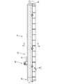
- FIG. 1 is a perspective view showing a state in which the wire harness routing device according to the first embodiment is attached to a seat. Side view showing the state where the wire harness routing device is attached to the seat.
- Enlarged side view of the main parts of the wire harness installation device Sectional view taken along the line AA of FIG. Sectional view taken along the line BB of FIG.
- Cross-sectional view showing a state in which the inner harness and the outer harness are arranged side by side.
- the present embodiment illustrates a wire harness routing device 10 for allocating a wire harness 11 between a floor portion (not shown) of a vehicle and a seat S (not shown).
- the seat S is slidable in the front-rear direction with respect to a pair of rails 20 fixed to the floor of a vehicle compartment of a vehicle by bolting or the like.
- the seat S is equipped with various electric components such as an electric reclining device, a seat heater, a sensor for detecting whether or not a passenger is seated, and a socket for supplying power.
- the wire harness routing device 10 accommodates the rail 20, the slider 30 slidably arranged in the rail 20, the wire harness 11, and a part of the wire harness 11.
- the harness accommodating portion 50 is provided.
- the rails 20 are made of metal, and a pair of rails 20 are provided on the floor with respect to the seat S. As shown in FIG. 1, the pair of rails 20 are arranged side by side in parallel with a space between them in the left-right direction. Each rail 20 has a shape extending linearly in the front-rear direction, and is opened in a substantially rectangular shape in the front-rear direction.
- any metal such as stainless steel, aluminum, and an aluminum alloy can be appropriately selected as needed.
- a slider 30 can be inserted in each rail 20 in the front-rear direction, and a through groove 23 penetrating in the up-down direction extends in the front-rear direction on the upper plate of each rail 20. Has been formed.
- the slider 30 is made of, for example, synthetic resin or metal, and as shown in FIGS. 3 and 4, the slider 30 is located at the front position where the slider 30 is arranged at the front end portion of the rail 20, and as shown in FIGS. In addition, the slider 30 is slidable in the front-rear direction from the rear position arranged at the rear end of the rail 20.
- the slider 30 has a rectangular parallelepiped insertion portion 31 inside the rail 20, and a mounting portion 32 that projects upward from the through groove 23 of the rail 20 in a plate shape.
- the mounting portion 32 is formed over the entire length of the slider 30 in the front-rear direction, and is fixed to the lower end portion of the seat S by bolts or the like, for example, as shown in FIG. Therefore, when the mounting portion 32 is fixed to the seat S, the seat S moves in the front-rear direction as the slider 30 slides in the rail in the front-rear direction.
- a guide protector 40 through which the wire harness 11 extending from the seat S is inserted is attached to the front end of the slider 30.
- the wire harness 11 is arranged between the floor of the vehicle body and the seat S.
- the end portion of the wire harness 11 on the vehicle body side is connected to a device such as an ECU (Electronic Control Unit), and power and signal transmission between the device on the vehicle body side and the electrical components of the seat S is performed via the wire harness 11. Transmission and reception is performed.
- ECU Electronic Control Unit
- the wire harness 11 includes a plurality of covered electric wires W in which a core wire is covered with an insulating coating, and a pair of base members 12 that sandwich and fix the plurality of covered electric wires W from both sides. doing.
- the wire harness 11 in the present embodiment is configured such that four covered electric wires W are sandwiched between a pair of base members 12 from both sides.
- Each covered electric wire W is connected to various electrical components provided on the sheet S.
- Each of the covered electric wires W has a base portion at one end of the covered electric wire W drawn from the guide protector 40 to the sheet S side and the other end portion of the covered electric wire W drawn from the harness accommodating portion 50 described later to the vehicle body side. It is routed in a state where it is not fixed to the member 12.
- the pair of base members 12 are made of sheet-shaped non-woven fabric.
- the non-woven fabric is a fabric formed by entwining or adhering fibers, and examples thereof include a fiber sheet, a web (a thin film-like sheet composed only of fibers), or a bat (blanket-like fibers).
- the base member 12 is made of a fiber sheet.
- the base member 12 may be a woven fabric made by weaving natural fibers or synthetic fibers.
- a plurality of covered electric wires W are fixed to the base member 12 side by side along the base member at approximately the central portion in the vertical direction.
- the covered electric wire W is fixed to the base member 12 by joining the covered electric wire W to the base member 12 by ultrasonic welding or heat welding, fixing the covered electric wire W by an adhesive or an adhesive, or by using the covered electric wire W as a base. It is fixed by a known fixing method such as sewing on the member 12.
- the plurality of coated electric wires W fixed to the base member 12 are arranged flat side by side so that no gap is formed between the adjacent coated electric wires W.
- a portion where the plurality of covered electric wires W are fixed to the base member 12 is a harness main body 13, and the harness main body 13 can be bent in a direction orthogonal to a direction in which the plurality of covered electric wires W are arranged (vertical direction). It is said that.
- the guide protector 40 is made of an insulating synthetic resin, and changes the direction of the wire harness 11 forward while accommodating the wire harness 11 pulled downward from the seat S inside.
- the guide protector 40 is fixed to the front end portion of the slider 30 by a known method such as a bolt or an adhesive.
- the guide protector 40 is arranged over the inside and outside of the rail 20 through the through groove 23 of the rail 20.
- the guide protector 40 holds the wire harness 11 at the front end of the guide protector 40 while holding the rail 20.
- An electric wire holding portion (not shown) for pulling out the wire harness 11 is provided inside. Therefore, the wire harness 11 pulled out into the rail 20 follows the movement of the slider 30 in the front-rear direction and is put in and out from the front end opening of the rail 20.
- a harness accommodating portion 50 for accommodating the extra length portion of the wire harness 11 pulled out from the front end opening of the rail 20 is attached to the front end portion of the rail 20.
- the harness accommodating portion 50 includes a guide portion 60 that guides an extra length portion of the wire harness 11 pulled out from the rail 20 toward the left side, and a surplus portion of the wire harness 11 that is guided by the guide portion 60. It has an extra length accommodating portion 70 for accommodating a long portion.
- the guide part 60 is arranged on the right front part of the harness accommodating part 50.
- the guide portion 60 includes a guide constant pulley 62 that gently bends the wire harness 11 pulled out from the front end opening of the rail 20 toward the left side in an L shape.
- the guide constant pulley 62 is configured to include a substantially cylindrical support shaft 63 that is fixed to the bottom of the guide portion 60 and is long in the vertical direction, and a rotating portion 64 that is rotatably assembled to the support shaft 63.
- the rotating portion 64 has a cylindrical shaft portion 65 along which the wire harness 11 is arranged.
- the rotating portion 64 can move the wire harness 11 smoothly in the guide constant pulley 62 by rotating the shaft portion 65 around the support shaft 63.
- the extra length accommodating portion 70 is formed long in the front-rear direction along the left side portion of the rail 20.
- the extra length portion of the wire harness 11 pulled out from the rail 20 is wound in an elliptical shape long in the front-rear direction and accommodated.
- the extra length accommodating portion 70 includes a guide portion 71 that bends the wire harness 11 introduced from the guide portion 60 backward, and a direction restricting portion 76 that bends the wire harness 11 extending from the guide portion 71 forward.
- a front pulley 80 that bends the wire harness 11 extending from the direction restricting portion 76 rearward, a rear pulley 90 that curves the wire harness 11 extending from the front pulley 80 forward, and a wire harness 11 extending from the rear pulley 90 are provided. It is configured to include a harness holding portion 72 for holding.
- the guide portion 71 is horizontally long at the front end of the extra length accommodation portion 70.
- the left end of the guide portion 71 is curved toward the rear.
- the guide portion 71 bends the wire harness 11 guided by the guide portion 60 gently rearward by arranging the wire harness 11 along the front surface 71A of the guide portion 71.
- the direction regulating portion 76 has a long shape in the left-right direction, and is integrally formed with a support arm 78 arranged in the extra length accommodating portion 70. As shown in FIG. 5, the support arm 78 has a pair of support plates 79 arranged on both sides in the vertical direction in the extra length accommodating portion 70. The direction restricting portion 76 is formed between the rear end portions of the pair of support plates 79.
- the direction restricting portion 76 has a shape gently curved rearward as shown in FIG.
- a wire harness 11 is wound counterclockwise and arranged on the rear surface of the direction regulating portion 76. Therefore, the extra length portion of the wire harness 11 slides with the rear surface of the direction regulating portion 76 as it is taken in and out of the harness accommodating portion 50, and moves between the guide portion 71 and the front pulley 80. Has become.
- the front pulley 80 has a configuration similar to that of the guide constant pulley 62 of the guide portion 60, and as shown in FIG. 4, has a vertically long cylindrical shape fixed to the bottom portion 70D of the extra length accommodating portion 70 by a bolt (not shown). It is configured to include a support shaft 81 and a cylindrical rotating portion 82 rotatably assembled to the support shaft 81.
- the wire harness 11 is arranged along the front end portion of the shaft portion 83 of the rotating portion 82, and the shaft portion 83 rotates around the support shaft 81, whereby the wire harness 11 and the direction restricting portion 76 are moved backward. It is designed to move smoothly with and from the pulley 90.
- the rear pulley 90 includes a cylindrical support shaft 93, which is fixed between the pair of support plates 79 of the support arm 78 by bolts B and which is long in the vertical direction, and rotatably assembled to the support shaft 93. It is configured to include a cylindrical rotating portion 94 to be attached.
- the rear pulley 90 is arranged in front of the direction restricting portion 76 by the support shaft 93 being fixed to the front end portions of the pair of support plates 79.
- the rotating portion 94 has a cylindrical shaft portion 95 along which the wire harness 11 is arranged.
- the wire harness 11 is arranged along the rear end portion of the shaft portion 95, and the shaft portion 95 rotates about the support shaft 93 to move the wire harness 11 to the front pulley 80 and the harness holding portion 72. It is designed to move smoothly between them.
- the diameter of the shaft portion 95 is larger than the length of the direction regulating portion 76 in the left-right direction so that the wire harness 11 extending in the front-rear direction from the direction regulating portion 76 does not come into contact with the wire harness 11 arranged in the rear pulley 90. It is set small.
- the wire harness 11 is wound in the clockwise direction around the direction restricting portion 76, the front pulley 80, and the rear pulley 90, and is arranged in the extra length accommodation portion 70.
- the outer harness 11A which is the wire harness 11 arranged between the guide portion 71 and the direction regulating portion 76, the front pulley 80, and the rear pulley 90.
- the inner harness 11B which is the wire harness 11 arranged between the two, is arranged side by side in the left-right direction in a state of being close to each other in the left-right direction.
- the outer harness 11C which is the wire harness 11 arranged between the direction restricting portion 76 and the front pulley 80
- the inner harness 11D which is the wire harness 11 arranged between the rear pulley 90 and the harness holding portion 72. And are arranged side by side in the left-right direction in a state of being close to each other in the left-right direction.
- the harness holding portion 72 is arranged immediately after the front pulley 80.
- the harness holding portion 72 holds the end portion of the harness body 13 of the wire harness 11 extending forward from the rear pulley 90 on the vehicle body side.
- the plurality of covered electric wires W drawn out forward from the harness main body 13 held by the harness holding part 72 are drawn out to the floor part of the vehicle body from a substantially rectangular outlet 70A provided in the bottom 70D of the extra length accommodating part 70. It is like this.
- the pair of support plates 79 of the support arm 78 can be fitted into the pair of groove portions 73 provided in the bottom portion 70D and the ceiling portion 70U of the extra length accommodating portion 70, respectively.
- the head B1 of the bolt B for fixing the support plate 79 and the support shaft 93 is vertically penetrated between the bottom portion 70D of the extra length accommodation portion 70 and the pair of groove portions 73 in the ceiling portion 70U. It can be fitted into the groove 74.
- Each of the groove portion 73, the through groove 74 and the support plate 79 is formed to extend in the front-rear direction.
- the support plate 79 slides in the groove portion 73 in the front-rear direction, and the head B1 of the bolt B slides in the through groove 74 in the front-rear direction, so that the support arm 78 moves together with the direction restricting portion 76 and the rear pulley 90. It is configured to move in the front-rear direction within the extra length accommodation portion 70.
- a constant force spring P is fixed to the rear end of the support arm 78.
- the constant load spring P is formed by winding a long leaf spring, and the support arm 78 is biased rearward together with the direction regulating portion 76 and the rear pulley 90 by the biasing force of the constant load spring P. ..
- the direction regulating portion 76 and the rear pulley 90 are moved backward by the biasing force of the constant load spring P so as to be separated from the front pulley 80. Move towards.
- the pulling-out force resists the biasing force of the constant load spring P and the direction regulating portion 76 and the rear pulley 90 move forward. It moves and approaches the front pulley 80.
- the length dimension of the wire harness 11 between the direction restricting portion 76 and the rear pulley 90 and the front pulley 80 changes, and the inner harnesses 11B and 11D and the outer harnesses 11A and 11C are always close to each other in the left-right direction. To be maintained at.
- the cross-sectional area of the plurality of coated electric wires W in the wire harness 11 in the left-right direction intersecting the axial direction of at least one coated electric wire W is different from the cross-sectional area of the other coated electric wires W.
- the cross section of each covered electric wire W is formed in a square shape with rounded four corners.
- the covered electric wire W located at the uppermost stage is the smallest diameter electric wire WS having the smallest cross-sectional area, and the covered electric wires W below the smallest diameter electric wire WS are traversed downward.
- the non-minimum diameter electric wire WL has a large area.
- the rectangular shape is a quadrangular shape including a square and a rectangle, and is also called a rectangular shape.
- the thickness dimension (horizontal dimension) L1 of the covered electric wire W in the left-right direction which is the thickness direction of the base member 12 is the same as that in the arrangement direction of the covered electric wires W. It is substantially the same as the width dimension (vertical dimension) L2.
- “substantially the same” includes the case where the thickness dimension L1 and the width dimension L2 are the same, and the case where the thickness dimension L1 and the width dimension L2 are different and can be regarded as substantially the same. Therefore, the cross section of the minimum diameter electric wire WS is substantially rectangular.
- the thickness dimension L3 of the covered electric wire W is set to be substantially the same as the thickness dimension L1 of the minimum diameter electric wire WS. ..
- “substantially the same” means that the thickness dimension L3 of the covered electric wire W is the same as the thickness dimension L1 of the minimum diameter electric wire WS, and the thickness dimension L3 of the covered electric wire W is the thickness of the minimum diameter electric wire WS. It includes a case where the dimension L1 may be substantially the same even if the dimension L1 is different.
- the width dimension of the non-minimum diameter electric wire WL is larger than the thickness dimension L1 of the minimum diameter electric wire WS, and the cross section of the non-minimum diameter electric wire WL has a substantially rectangular shape that is long in the width direction (vertical direction). I am doing it.
- the thickness dimensions of the adjacent covered electric wires W in the plurality of covered electric wires W including the minimum diameter electric wire WS are all substantially the same, and the thickness dimension in the harness body 13 of the wire harness 11 is the entire width (cover It is uniform over the arrangement direction of the electric wires W).
- the inner harnesses 11B and 11D and the outer harnesses 11A and 11C are routed close to each other in the left-right direction in the extra length accommodating portion 70, for example, flatten a plurality of covered electric wires having different electric wire diameters.
- the space in the thickness direction of the wire harness 11 can be reduced as compared with the arranged conventional wire harnesses, and the space of the wire harness 11 can be saved.
- This embodiment has the above configuration, and subsequently, the operations and effects of the wire harness 11 and the wire harness routing device 10 will be described.
- the present embodiment includes a sheet-shaped base member 12 and a plurality of covered electric wires W arranged and fixed along the base member 12, and at least one covered electric wire W among the plurality of covered electric wires W.
- the cross-sectional area which is the cross-sectional area in the direction intersecting the axial direction of, is different from the cross-sectional areas of other covered electric wires W, and the thickness dimension of the covered electric wires W in the thickness direction of the base member 12 is adjacent to the covered electric wires. It is substantially the same as the thickness dimension of W.
- the covered electric wire W having the smallest cross-sectional area among the plurality of covered electric wires W is the minimum diameter electric wire WS and the covered electric wire W having the larger cross sectional area than the minimum diameter electric wire WS is the non-minimum diameter electric wire WL, the plurality of covered electric wires
- the width dimension of the non-minimum diameter electric wire WL in the arrangement direction of W is larger than the thickness dimension L1 of the minimum diameter electric wire WS.
- the thickness dimension of the coated wire is substantially the same as the thickness dimension of the adjacent coated wire and the width dimension of the non-minimum diameter wire is smaller than the thickness dimension of the minimum diameter wire, the thickness of the wire harness. Although there is no variation in the thickness direction, the thickness of the wire harness becomes larger than that in the width direction. Therefore, it is feared that the wire harness cannot be installed in the limited area.
- the width dimension of the non-minimum diameter electric wire WL becomes larger than the thickness dimension L1 of the minimum diameter electric wire WS, so that the thickness dimension of the wire harness 11 is prevented from becoming larger than the width direction. be able to.
- the minimum diameter electric wire WS has substantially the same thickness dimension L1 and width dimension L2, and the thickness dimension of the non-minimum diameter electric wire WL is substantially the same as the thickness dimension L1 of the minimum diameter electric wire WS. Are set to the same.
- the wire harness 11 is compared with the case where the width dimension of the minimum diameter electric wire is larger than the thickness dimension. It is possible to suppress the height dimension of the wire harness 11 from increasing while suppressing the width dimension of the wire harness from unnecessarily increasing.
- the cross section of at least the non-minimum diameter electric wire WL among the plurality of covered electric wires W is flat, they are adjacent to each other as compared with the case where the cross section of the non-minimum diameter electric wire is formed in an elliptical shape, for example.
- the dead space between the covered electric wires W can be eliminated, and the installation area of the non-minimum diameter electric wire WL with respect to the base member 12 can be increased.
- the area to fix the covered electric wire W to the base member 12 by ultrasonic welding, heat welding, or an adhesive or an adhesive can be increased, at least the space for the wire harness 11 can be reduced and at least The fixing strength of the minimum diameter electric wire WL to the base member 12 can be improved.
- the wire harness 11, the inner harnesses 11B and 11D arranged inside by winding and arranging the wire harness 11 and the outer harnesses 11A and 11C arranged outside are housed in close proximity to each other. Since the harness accommodating portion 50 is provided, the inner harnesses 11B and 11D are compared with, for example, a wire harness arranging device that applies a conventional wire harness in which a plurality of covered electric wires having different electric wire diameters are flatly arranged. It is possible to reduce the space in the thickness direction of the wire harness 11 in the region where the outer harnesses 11A and 11C are close to each other. As a result, it is possible to prevent the harness accommodating portion 50 from becoming larger in the left-right direction, and it is possible to prevent the wire harness routing device 10 from becoming larger.
- the wire harness 111 of the second embodiment is a modification of the shape of the minimum diameter electric wire WS of the wire harness 11 of the first embodiment, and has the same configuration, action, and effect as that of the first embodiment. The description is omitted.
- the same components as those in the first embodiment are designated by the same reference numerals.
- the shape of the cross section of the minimum diameter electric wire WS1 is formed in a circular shape.
- the diameter dimension L11 of the minimum diameter electric wire WS1 and the thickness dimension L3 of the non-minimum diameter electric wire WL are substantially the same.
- the thickness dimension and width dimension of the minimum diameter electric wire WS1 and the thickness dimension L3 of the non-minimum diameter electric wire WL are substantially the same.
- the conventional covered electric wire is applied as the minimum diameter electric wire WS, and it is not necessary to newly manufacture the minimum diameter electric wire WS. Therefore, the manufacturing cost of the wire harness 111 can be reduced. You can do it.
- the techniques disclosed herein are not limited to the embodiments described above and in the drawings, and include, for example, various aspects such as: (1) In the above embodiment, the cross-sectional area of the covered electric wire W in the wire harness 11 is configured to increase as it goes downward. However, the arrangement of the covered electric wires in the wire harness is not limited to this, and may be arbitrarily selected. (2) In the above embodiment, the thickness dimension of the non-minimum diameter electric wire WL is set to be substantially the same as the thickness dimension L1 of the minimum diameter electric wire WS. However, the present invention is not limited to this, and the thickness dimension of the minimum diameter electric wire may be set to be substantially the same as the thickness dimension of any non-minimum diameter electric wire.
- the wire harness routing device 10 to which the wire harness 11 is applied is shown as an example.
- the present invention is not limited to this, and the techniques of the present specification may be applied to wire harnesses to be arranged on the roof, floor, and door panel of a vehicle.
- Wire harness routing device 11 Wire harness 11A, 11C: Outer harness 11B, 11D: Inner harness 12: Base member 50: Harness accommodating portion 70: Extra length accommodating portion (example of "harness accommodating portion") W: Coated electric wire (an example of "electric wire”) WL: Non-minimum diameter electric wire WS: Minimum diameter electric wire
Landscapes
- Engineering & Computer Science (AREA)
- Mechanical Engineering (AREA)
- Architecture (AREA)
- Civil Engineering (AREA)
- Structural Engineering (AREA)
- Electric Cable Arrangement Between Relatively Moving Parts (AREA)
- Insulated Conductors (AREA)
- Details Of Indoor Wiring (AREA)
Abstract
A wire harness 11 disclosed herein comprises a sheet-like base member 12 and a plurality of coated electric wires W arrayed and fixed along the base member 12, and has a configuration in which: a cross-sectional area of at least one coated electric wire W among the plurality of coated electric wires W is different from a cross-sectional area of other coated electric wires W; and a thickness dimension of each of the coated electric wires W is substantially the same as a thickness dimension of an adjacent coated electric wire W.
Description
本明細書によって開示される技術は、ワイヤハーネスおよびワイヤハーネス配索装置に関する。
The technology disclosed in the present specification relates to a wire harness and a wire harness routing device.
例えば、車両に搭載された機器間を接続するワイヤハーネスとして、特開2001-136632号公報(下記特許文献1)に記載のものが知られている。このワイヤハーネスは、断面形状が円形の複数の電線を保持シートによって山形状に束ねることによって構成されている。
For example, as a wire harness for connecting devices mounted on a vehicle, those described in Japanese Patent Application Laid-Open No. 2001-136632 (Patent Document 1 below) are known. This wire harness is configured by bundling a plurality of electric wires each having a circular cross section into a mountain shape by a holding sheet.
ところで、このようなワイヤハーネスを車両のルーフや床部などに配索する場合、配索スペースが限られている場合には、ワイヤハーネスを配索できなくなる虞がある。このため、配索スペースが限られている場合には、複数の電線を平らに並べることによってワイヤハーネスを扁平な状態に構成して配索することが考えられる。
By the way, when installing such a wire harness on the roof or floor of a vehicle, if the installation space is limited, it may not be possible to install the wire harness. Therefore, when the wiring space is limited, it is conceivable to arrange the plurality of electric wires flat to form the wire harness in a flat state and arrange the wires.
しかしながら、図9および図10に示すように、複数の電線1の電線径にばらつきがあると、ワイヤハーネス2の表面3に凹凸が生じ、ワイヤハーネス2の厚みのばらつきによってワイヤハーネス2の厚さ方向にデッドスペースDが生じてしまう。
However, as shown in FIGS. 9 and 10, if the wire diameters of the plurality of electric wires 1 vary, the surface 3 of the wire harness 2 becomes uneven, and the thickness of the wire harness 2 varies due to the variation in the thickness of the wire harness 2. A dead space D is generated in the direction.
本明細書では、ワイヤハーネスの省スペース化を図る技術を開示する。
This specification discloses a technique for saving space in the wire harness.
本明細書によって開示される技術は、シート状のベース部材と、前記ベース部材に沿うように並べて固定された複数の電線と、を備え、前記複数の電線のうち少なくとも1本の前記電線の軸方向と交差する方向の断面積である横断面積は、他の前記電線の横断面積と異なっており、前記ベース部材の厚さ方向についての前記電線の厚さ寸法は隣り合う前記電線の厚さ寸法と実質的に同一となっている構成とした。ここで、実質的同一とは、隣り合う電線の厚さ寸法が同一の場合と、隣り合う電線の厚さ寸法が異なる場合でも実質的に同一とみなしうる場合を含む。
The technique disclosed herein includes a sheet-shaped base member and a plurality of electric wires fixed side by side along the base member, and the shaft of at least one of the plurality of electric wires. The cross-sectional area that is the cross-sectional area in the direction intersecting the direction is different from the cross-sectional area of the other electric wire, and the thickness dimension of the electric wire in the thickness direction of the base member is the thickness dimension of the adjacent electric wires. And the configuration is substantially the same. Here, “substantially the same” includes the case where the thickness dimensions of adjacent electric wires are the same and the case where the thickness dimensions of adjacent electric wires can be regarded as substantially the same even when the thickness dimensions are different.
このような構成のワイヤハーネスによると、複数の電線の厚さ寸法が全て実質的に同一となるから、ワイヤハーネスの厚みにばらつきが生じることを防ぐことができる。これにより、ワイヤハーネスの厚さ方向にデッドスペースが生じることを防ぎ、ワイヤハーネスの省スペース化を図ることができる。
According to the wire harness having such a configuration, since the thickness dimensions of the plurality of electric wires are all substantially the same, it is possible to prevent variations in the thickness of the wire harness. As a result, it is possible to prevent a dead space from being generated in the thickness direction of the wire harness and to save space in the wire harness.
本明細書によって開示されるワイヤハーネスは、以下の構成としてもよい。
前記複数の電線のうち横断面積が最も小さい最小径電線よりも横断面積が大きい非最小径電線の並び方向についての幅寸法は、前記最小径電線の厚さ寸法よりも大きくなっている構成としてもよい。 The wire harness disclosed by the present specification may have the following configurations.
The width dimension in the arrangement direction of the non-minimum diameter electric wire having a larger cross sectional area than the smallest diameter electric wire having the smallest cross sectional area among the plurality of electric wires may be larger than the thickness dimension of the minimum diameter electric wire. Good.
例えば、被覆電線の厚さ寸法が隣り合う被覆電線の厚さ寸法と実質的に同一であり、非最小径電線の幅寸法が、最小径電線の厚さ寸法よりも小さい場合、ワイヤハーネスの厚さ方向のばらつきはなくなるものの、ワイヤハーネスの厚さ寸法が幅方向よりも大きくなってしまう。したがって、限られた領域にワイヤハーネスを配索することができなくなることが懸念される。
For example, if the thickness dimension of the coated wire is substantially the same as the thickness dimension of the adjacent coated wire and the width dimension of the non-minimum diameter wire is smaller than the thickness dimension of the minimum diameter wire, the thickness of the wire harness. Although there is no variation in the thickness direction, the thickness of the wire harness becomes larger than that in the width direction. Therefore, it is feared that the wire harness cannot be installed in the limited area.
ところが、このような構成によると、非最小径電線の幅寸法が、最小径電線の厚さ寸法よりも大きくなっているからワイヤハーネスの厚さ寸法が幅方向よりも大きくなることを防ぐことができる。
However, according to such a configuration, since the width dimension of the non-minimum diameter electric wire is larger than the thickness dimension of the minimum diameter electric wire, it is possible to prevent the thickness dimension of the wire harness from becoming larger than the width direction. it can.
前記最小径電線は、厚さ寸法と幅寸法とが実質的に同一とされており、前記非最小径電線の厚さ寸法は、前記最小径電線の厚さ寸法と実質的に同一に設定されている構成としてもよい。ここで、実質的同一とは、厚さ寸法と幅寸法とが同一の場合と、厚さ寸法と幅寸法とが異なる場合でも実質的に同一とみなしうる場合を含む。
The thickness dimension and the width dimension of the minimum diameter electric wire are substantially the same, and the thickness dimension of the non-minimum diameter electric wire is set to be substantially the same as the thickness dimension of the minimum diameter electric wire. It may be configured to have. Here, “substantially the same” includes the case where the thickness dimension and the width dimension are the same, and the case where the thickness dimension and the width dimension are different and can be regarded as substantially the same.
このような構成によると、最小径電線の厚さ寸法と幅寸法とが実質的に同一となっているから、例えば、最小径電線の幅寸法が厚さ寸法よりも大きい場合に比べて、ワイヤハーネスの幅寸法が無駄に大きくなることを抑制しつつ、ワイヤハーネスの高さ寸法が大きくなることを抑制することができる。
According to such a configuration, the thickness dimension and the width dimension of the minimum diameter electric wire are substantially the same, so that the wire is compared with the case where the width dimension of the minimum diameter electric wire is larger than the thickness dimension, for example. It is possible to prevent the height dimension of the wire harness from becoming large while suppressing the width dimension of the harness from becoming unnecessarily large.
前記複数の電線のうち少なくとも前記非最小径電線の横断面は、方形状とされている構成としてもよい。
このような構成によると、例えば、非最小径電線の横断面が楕円形状に構成される場合に比べて、隣り合う被覆電線の間のデッドスペースをなくすと共に、ベース部材に対する非最小径電線の設置面積を大きくすることができる。これにより、ワイヤハーネスの省スペース化を図りつつ、ベース部材に対する非最小径電線の固着強度を向上させることができる。 At least the non-minimum diameter electric wire of the plurality of electric wires may have a rectangular cross section.
According to such a configuration, compared with the case where the cross section of the non-minimum diameter electric wire is formed into an elliptical shape, for example, the dead space between adjacent covered electric wires is eliminated and the non-minimum diameter electric wire is installed on the base member. The area can be increased. As a result, it is possible to improve the fixing strength of the non-minimum-diameter electric wire to the base member while saving the space of the wire harness.
前記最小径電線は、横断面が円形状とされている構成としてもよい。
このような構成によると、既存の電線を最小径電線として適用することができる。これにより、最小径電線を新たに製造する必要がなく、製造コストを削減することができる。 The minimum diameter electric wire may have a circular cross section.
With such a configuration, an existing electric wire can be applied as the minimum diameter electric wire. Thereby, it is not necessary to newly manufacture the minimum diameter electric wire, and the manufacturing cost can be reduced.
本明細書によって開示されるワイヤハーネス配索装置は、前記ワイヤハーネスと、前記ワイヤハーネスを巻いて配置することにより内側に配された内側ハーネスと外側に配された外側ハーネスとを近接させて収容するハーネス収容部とを備えて構成されている。
A wire harness arranging device disclosed by the present specification accommodates the wire harness, the inner harness arranged inside by arranging the wire harness and the outer harness arranged outside, in close proximity to each other. And a harness accommodating portion that operates.
このような構成のワイヤハーネス配索装置によると、例えば、電線径にばらつきのある複数の電線を平らに並べたワイヤハーネスを備えたハーネス配索装置に比べて、内側ハーネスと外側ハーネスとが近接して配された際に、ワイヤハーネスの厚さ方向についてのスペースを削減することができる。これにより、ワイヤハーネス配索装置が大型化することを抑制することができる。
According to the wire harness wiring device having such a configuration, the inner harness and the outer harness are closer to each other than, for example, a harness wiring device having a wire harness in which a plurality of electric wires having various wire diameters are arranged flat. When they are arranged, the space in the thickness direction of the wire harness can be reduced. As a result, it is possible to prevent the wire harness routing device from becoming large in size.
本明細書によって開示される技術によれば、ワイヤハーネスの省スペース化を図ることができる。
According to the technique disclosed in the present specification, it is possible to save the space of the wire harness.
<実施形態1>
本明細書に開示された技術における一実施形態について図1から図7を参照して説明する。 <Embodiment 1>
One embodiment of the technology disclosed in this specification will be described with reference to FIGS. 1 to 7.
本明細書に開示された技術における一実施形態について図1から図7を参照して説明する。 <
One embodiment of the technology disclosed in this specification will be described with reference to FIGS. 1 to 7.
本実施形態は、図1または図2に示すように、車両の図示しない床部とシートSとの間にワイヤハーネス11を配索するワイヤハーネス配索装置10を例示している。
As shown in FIG. 1 or 2, the present embodiment illustrates a wire harness routing device 10 for allocating a wire harness 11 between a floor portion (not shown) of a vehicle and a seat S (not shown).
シートSは、車両の車室の床上などにボルト締結等によって固定された一対のレール20に対して前後方向にスライド可能とされている。
シートSには、例えば、電動リクライニング装置、シートヒータ、乗員の着座の有無を検出するセンサ、電源供給用のソケットなどの各種電装品が備えられている。 The seat S is slidable in the front-rear direction with respect to a pair ofrails 20 fixed to the floor of a vehicle compartment of a vehicle by bolting or the like.
The seat S is equipped with various electric components such as an electric reclining device, a seat heater, a sensor for detecting whether or not a passenger is seated, and a socket for supplying power.
シートSには、例えば、電動リクライニング装置、シートヒータ、乗員の着座の有無を検出するセンサ、電源供給用のソケットなどの各種電装品が備えられている。 The seat S is slidable in the front-rear direction with respect to a pair of
The seat S is equipped with various electric components such as an electric reclining device, a seat heater, a sensor for detecting whether or not a passenger is seated, and a socket for supplying power.
ワイヤハーネス配索装置10は、図2から図5に示すように、レール20と、レール20内にスライド可能に配置されるスライダ30と、ワイヤハーネス11と、ワイヤハーネス11の一部を収容するハーネス収容部50とを備えている。
As shown in FIGS. 2 to 5, the wire harness routing device 10 accommodates the rail 20, the slider 30 slidably arranged in the rail 20, the wire harness 11, and a part of the wire harness 11. The harness accommodating portion 50 is provided.
レール20は、金属製であって、シートSに対して床上に一対設けられている。一対のレール20は、図1に示すように、左右方向に間隔を開けて、平行に並んで配されている。各レール20は、前後方向に直線状に延びた形態をなしており、前後方向に略矩形状に開口している。レール20を構成する金属としては、ステンレス、アルミニウム、アルミニウム合金等、必要に応じて任意の金属を適宜に選択できる。
The rails 20 are made of metal, and a pair of rails 20 are provided on the floor with respect to the seat S. As shown in FIG. 1, the pair of rails 20 are arranged side by side in parallel with a space between them in the left-right direction. Each rail 20 has a shape extending linearly in the front-rear direction, and is opened in a substantially rectangular shape in the front-rear direction. As the metal constituting the rail 20, any metal such as stainless steel, aluminum, and an aluminum alloy can be appropriately selected as needed.
各レール20内には、図5に示すように、スライダ30が前後方向に挿通可能とされており、各レール20の上板には、上下方向に貫通する通し溝23が前後方向に延びて形成されている。
As shown in FIG. 5, a slider 30 can be inserted in each rail 20 in the front-rear direction, and a through groove 23 penetrating in the up-down direction extends in the front-rear direction on the upper plate of each rail 20. Has been formed.
スライダ30は、例えば、合成樹脂製または金属製であって、図3および図4に示すように、スライダ30がレール20の前端部に配置された前方位置と、図1および図2に示すように、スライダ30がレール20の後端部に配置された後方位置との間を前後方向にスライド可能とされている。
The slider 30 is made of, for example, synthetic resin or metal, and as shown in FIGS. 3 and 4, the slider 30 is located at the front position where the slider 30 is arranged at the front end portion of the rail 20, and as shown in FIGS. In addition, the slider 30 is slidable in the front-rear direction from the rear position arranged at the rear end of the rail 20.
スライダ30は、図4および図5に示すように、レール20内に直方体状の挿通部31と、レール20の通し溝23から上方に向けて板状に突出する取付部32とを有している。取付部32は、スライダ30の前後方向の全長に亘って形成されており、例えば、図2に示すように、ボルト等によりシートSに下端部に固定されるようになっている。したがって、取付部32がシートSに固定されると、スライダ30がレール内を前後方向にスライドするに伴ってシートSが前後方向に移動するようになっている。
As shown in FIGS. 4 and 5, the slider 30 has a rectangular parallelepiped insertion portion 31 inside the rail 20, and a mounting portion 32 that projects upward from the through groove 23 of the rail 20 in a plate shape. There is. The mounting portion 32 is formed over the entire length of the slider 30 in the front-rear direction, and is fixed to the lower end portion of the seat S by bolts or the like, for example, as shown in FIG. Therefore, when the mounting portion 32 is fixed to the seat S, the seat S moves in the front-rear direction as the slider 30 slides in the rail in the front-rear direction.
また、スライダ30の前端部には、図2から図4に示すように、シートSから延びるワイヤハーネス11が挿通されるガイドプロテクタ40が取り付けられている。
Further, as shown in FIGS. 2 to 4, a guide protector 40 through which the wire harness 11 extending from the seat S is inserted is attached to the front end of the slider 30.
ワイヤハーネス11は、車体の床部とシートSとの間に配索されている。ワイヤハーネス11における車体側の端部はECU(Electronic Control Unit)などの機器に接続されており、このワイヤハーネス11を介して車体側の機器とシートSの電装品との間で給電や信号の送受が行われる。
The wire harness 11 is arranged between the floor of the vehicle body and the seat S. The end portion of the wire harness 11 on the vehicle body side is connected to a device such as an ECU (Electronic Control Unit), and power and signal transmission between the device on the vehicle body side and the electrical components of the seat S is performed via the wire harness 11. Transmission and reception is performed.
ワイヤハーネス11は、図6および図7に示すように、芯線を絶縁被覆によって覆った複数本の被覆電線Wと、複数の被覆電線Wを両側から挟んで固定する一対のベース部材12とを有している。本実施形態におけるワイヤハーネス11は、4本の被覆電線Wが一対のベース部材12に両側から挟まれて構成されている。
As shown in FIGS. 6 and 7, the wire harness 11 includes a plurality of covered electric wires W in which a core wire is covered with an insulating coating, and a pair of base members 12 that sandwich and fix the plurality of covered electric wires W from both sides. doing. The wire harness 11 in the present embodiment is configured such that four covered electric wires W are sandwiched between a pair of base members 12 from both sides.
各被覆電線Wは、シートSに備えられた各種電装品に接続されている。各被覆電線Wは、ガイドプロテクタ40からシートS側に引き出される被覆電線Wの一方の端部と、後述するハーネス収容部50から車体側に引き出される被覆電線Wの他方の端部とは、ベース部材12に固定されない状態で配索されている。
Each covered electric wire W is connected to various electrical components provided on the sheet S. Each of the covered electric wires W has a base portion at one end of the covered electric wire W drawn from the guide protector 40 to the sheet S side and the other end portion of the covered electric wire W drawn from the harness accommodating portion 50 described later to the vehicle body side. It is routed in a state where it is not fixed to the member 12.
一対のベース部材12は、シート状をなす不織布によって形成されている。不織布は、繊維を絡ませたり接着したりして形成された布であって、例えば、繊維シート、ウェブ(繊維だけで構成された薄い膜状のシート)またはバット(毛布状の繊維)などが挙げられる。本実施形態では、ベース部材12は、繊維シートによって構成されている。また、ベース部材12は、天然繊維もしくは合成繊維を織って作った織布であってもよい。
The pair of base members 12 are made of sheet-shaped non-woven fabric. The non-woven fabric is a fabric formed by entwining or adhering fibers, and examples thereof include a fiber sheet, a web (a thin film-like sheet composed only of fibers), or a bat (blanket-like fibers). To be In this embodiment, the base member 12 is made of a fiber sheet. Further, the base member 12 may be a woven fabric made by weaving natural fibers or synthetic fibers.
ベース部材12には、図6および図7に示すように、複数の被覆電線Wが上下方向略中央部にベース部材に沿うように並べて固定されている。
As shown in FIGS. 6 and 7, a plurality of covered electric wires W are fixed to the base member 12 side by side along the base member at approximately the central portion in the vertical direction.
ベース部材12に対する被覆電線Wの固定は、ベース部材12に、超音波溶着や熱溶着によって被覆電線Wを接合したり、粘着剤や接着剤によって被覆電線Wを固定したり、被覆電線Wをベース部材12に縫い付けたりするなど、公知の固定方法によって固定されている。ベース部材12に固定された複数の被覆電線Wは、隣り合う被覆電線W間に隙間が生じないように平らに並んで配置されている。
The covered electric wire W is fixed to the base member 12 by joining the covered electric wire W to the base member 12 by ultrasonic welding or heat welding, fixing the covered electric wire W by an adhesive or an adhesive, or by using the covered electric wire W as a base. It is fixed by a known fixing method such as sewing on the member 12. The plurality of coated electric wires W fixed to the base member 12 are arranged flat side by side so that no gap is formed between the adjacent coated electric wires W.
ワイヤハーネス11において、複数の被覆電線Wがベース部材12に固定された部分はハーネス本体13とされ、ハーネス本体13は、複数の被覆電線Wが並ぶ方向(上下方向)と直交する方向に湾曲可能とされている。
In the wire harness 11, a portion where the plurality of covered electric wires W are fixed to the base member 12 is a harness main body 13, and the harness main body 13 can be bent in a direction orthogonal to a direction in which the plurality of covered electric wires W are arranged (vertical direction). It is said that.
ガイドプロテクタ40は、絶縁性の合成樹脂によって形成されており、シートSから下方に引き出されたワイヤハーネス11を内部に収容しつつ、ワイヤハーネス11の向きを前方向に向かって変更する。ガイドプロテクタ40は、ボルト、接着剤などの公知の手法によりスライダ30の前端部に固定されている。
The guide protector 40 is made of an insulating synthetic resin, and changes the direction of the wire harness 11 forward while accommodating the wire harness 11 pulled downward from the seat S inside. The guide protector 40 is fixed to the front end portion of the slider 30 by a known method such as a bolt or an adhesive.
ガイドプロテクタ40は、図4に示すように、レール20の通し溝23を通してレール20の内外に亘って配置されており、ガイドプロテクタ40の前端部には、ワイヤハーネス11を保持しつつ、レール20内にワイヤハーネス11を引き出す図示しない電線保持部が設けられている。したがって、レール20内に引き出されたワイヤハーネス11は、スライダ30の前後方向の移動に追従してレール20の前端開口から出し入れされるようになっている。
As shown in FIG. 4, the guide protector 40 is arranged over the inside and outside of the rail 20 through the through groove 23 of the rail 20. The guide protector 40 holds the wire harness 11 at the front end of the guide protector 40 while holding the rail 20. An electric wire holding portion (not shown) for pulling out the wire harness 11 is provided inside. Therefore, the wire harness 11 pulled out into the rail 20 follows the movement of the slider 30 in the front-rear direction and is put in and out from the front end opening of the rail 20.
レール20の前端部には、図1から図4に示すように、レール20の前端開口から引き出されたワイヤハーネス11の余長部分を収容するハーネス収容部50が取り付けられている。
As shown in FIGS. 1 to 4, a harness accommodating portion 50 for accommodating the extra length portion of the wire harness 11 pulled out from the front end opening of the rail 20 is attached to the front end portion of the rail 20.
ハーネス収容部50は、スライダ30の移動に伴ってワイヤハーネス11の余長部分が出し入れされる。ハーネス収容部50は、図4に示すように、レール20から引き出されるワイヤハーネス11の余長部分を左側方に向かって案内する案内部60と、案内部60から案内されたワイヤハーネス11の余長部分を収容する余長収容部70とを有している。
The extra length of the wire harness 11 is taken in and out of the harness accommodating portion 50 as the slider 30 moves. As shown in FIG. 4, the harness accommodating portion 50 includes a guide portion 60 that guides an extra length portion of the wire harness 11 pulled out from the rail 20 toward the left side, and a surplus portion of the wire harness 11 that is guided by the guide portion 60. It has an extra length accommodating portion 70 for accommodating a long portion.
案内部60は、ハーネス収容部50の右側前部に配置されている。案内部60は、レール20の前端開口から引き出されるワイヤハーネス11を左側方に向けて緩やかにL字状に湾曲させる案内定滑車62を備えている。
The guide part 60 is arranged on the right front part of the harness accommodating part 50. The guide portion 60 includes a guide constant pulley 62 that gently bends the wire harness 11 pulled out from the front end opening of the rail 20 toward the left side in an L shape.
案内定滑車62は、案内部60の底部に固定された上下方向に長い略円柱状の支持軸63と、支持軸63に回転可能に組み付けられる回転部64とを備えて構成されている。
The guide constant pulley 62 is configured to include a substantially cylindrical support shaft 63 that is fixed to the bottom of the guide portion 60 and is long in the vertical direction, and a rotating portion 64 that is rotatably assembled to the support shaft 63.
回転部64は、ワイヤハーネス11が沿って配置される円筒状の軸部65を有している。回転部64は、軸部65が支持軸63を中心に回転することより、案内定滑車62においてワイヤハーネス11を滑らかに移動させることができるようになっている。
The rotating portion 64 has a cylindrical shaft portion 65 along which the wire harness 11 is arranged. The rotating portion 64 can move the wire harness 11 smoothly in the guide constant pulley 62 by rotating the shaft portion 65 around the support shaft 63.
余長収容部70は、図4に示すように、レール20の左側部に沿うように前後方向に長く形成されている。余長収容部70内には、レール20から引き出されるワイヤハーネス11の余長部分が前後方向に長い楕円形状に巻かれて収容されるようになっている。
As shown in FIG. 4, the extra length accommodating portion 70 is formed long in the front-rear direction along the left side portion of the rail 20. In the extra length accommodating portion 70, the extra length portion of the wire harness 11 pulled out from the rail 20 is wound in an elliptical shape long in the front-rear direction and accommodated.
余長収容部70は、案内部60から導入されるワイヤハーネス11を後方に向けて湾曲させるガイド部71と、ガイド部71から延びるワイヤハーネス11を前方に向けて湾曲させる方向規制部76と、方向規制部76から延びるワイヤハーネス11を後方に向けて湾曲させる前滑車80と、前滑車80から延びるワイヤハーネス11を前方に向けて湾曲させる後滑車90と、後滑車90から延びるワイヤハーネス11を保持するハーネス保持部72とを備えて構成されている。
The extra length accommodating portion 70 includes a guide portion 71 that bends the wire harness 11 introduced from the guide portion 60 backward, and a direction restricting portion 76 that bends the wire harness 11 extending from the guide portion 71 forward. A front pulley 80 that bends the wire harness 11 extending from the direction restricting portion 76 rearward, a rear pulley 90 that curves the wire harness 11 extending from the front pulley 80 forward, and a wire harness 11 extending from the rear pulley 90 are provided. It is configured to include a harness holding portion 72 for holding.
ガイド部71は、余長収容部70の前端部において左右方向に横長に形成されている。ガイド部71は、左側の端部が後方に向かって湾曲している。ガイド部71は、案内部60から案内されたワイヤハーネス11をガイド部71の前面71Aに沿わせて配置することにより後方に向けて緩やかに湾曲させる。
The guide portion 71 is horizontally long at the front end of the extra length accommodation portion 70. The left end of the guide portion 71 is curved toward the rear. The guide portion 71 bends the wire harness 11 guided by the guide portion 60 gently rearward by arranging the wire harness 11 along the front surface 71A of the guide portion 71.
方向規制部76は、左右方向に長い形態とされ、余長収容部70内に配置される支持アーム78と一体に形成されている。支持アーム78は、図5に示すように、余長収容部70内の上下方向両側に配置された一対の支持板79を有している。方向規制部76は、一対の支持板79の後端部の間に形成されている。
The direction regulating portion 76 has a long shape in the left-right direction, and is integrally formed with a support arm 78 arranged in the extra length accommodating portion 70. As shown in FIG. 5, the support arm 78 has a pair of support plates 79 arranged on both sides in the vertical direction in the extra length accommodating portion 70. The direction restricting portion 76 is formed between the rear end portions of the pair of support plates 79.
方向規制部76は、図4に示すように、後方に向かって緩やかに湾曲した形態とされている。方向規制部76の後面には、ワイヤハーネス11が反時計回りに巻き付けられて配置されるようになっている。したがって、ワイヤハーネス11の余長部分は、ハーネス収容部50内に出し入れされることに伴って方向規制部76の後面と摺動し、ガイド部71と前滑車80との間を移動するようになっている。
The direction restricting portion 76 has a shape gently curved rearward as shown in FIG. A wire harness 11 is wound counterclockwise and arranged on the rear surface of the direction regulating portion 76. Therefore, the extra length portion of the wire harness 11 slides with the rear surface of the direction regulating portion 76 as it is taken in and out of the harness accommodating portion 50, and moves between the guide portion 71 and the front pulley 80. Has become.
前滑車80は、案内部60の案内定滑車62と同様の構成であって、図4に示すように、余長収容部70の底部70Dに図示しないボルトによって固定された上下方向長い円柱状の支持軸81と、支持軸81に回転可能に組み付けられる円筒状の回転部82とを備えて構成されている。
The front pulley 80 has a configuration similar to that of the guide constant pulley 62 of the guide portion 60, and as shown in FIG. 4, has a vertically long cylindrical shape fixed to the bottom portion 70D of the extra length accommodating portion 70 by a bolt (not shown). It is configured to include a support shaft 81 and a cylindrical rotating portion 82 rotatably assembled to the support shaft 81.
前滑車80は、ワイヤハーネス11が回転部82の軸部83の前端部に沿って配置され、軸部83が支持軸81を中心に回転することにより、ワイヤハーネス11を方向規制部76と後滑車90との間において滑らかに移動させるようになっている。
In the front pulley 80, the wire harness 11 is arranged along the front end portion of the shaft portion 83 of the rotating portion 82, and the shaft portion 83 rotates around the support shaft 81, whereby the wire harness 11 and the direction restricting portion 76 are moved backward. It is designed to move smoothly with and from the pulley 90.
後滑車90は、図4に示すように、支持アーム78の一対の支持板79の間にボルトBによって固定された上下方向に長い円柱状の支持軸93と、支持軸93に回転可能に組付けられる円筒状の回転部94とを備えて構成されている。
As shown in FIG. 4, the rear pulley 90 includes a cylindrical support shaft 93, which is fixed between the pair of support plates 79 of the support arm 78 by bolts B and which is long in the vertical direction, and rotatably assembled to the support shaft 93. It is configured to include a cylindrical rotating portion 94 to be attached.
後滑車90は、支持軸93が、一対の支持板79の前端部に固定されることによって方向規制部76の前方に配置されている。
回転部94は、ワイヤハーネス11が沿って配置される円筒状の軸部95を有している。 Therear pulley 90 is arranged in front of the direction restricting portion 76 by the support shaft 93 being fixed to the front end portions of the pair of support plates 79.
The rotatingportion 94 has a cylindrical shaft portion 95 along which the wire harness 11 is arranged.
回転部94は、ワイヤハーネス11が沿って配置される円筒状の軸部95を有している。 The
The rotating
後滑車90は、ワイヤハーネス11が軸部95の後端部に沿って配置され、軸部95が支持軸93を中心に回転することにより、ワイヤハーネス11を前滑車80とハーネス保持部72との間において滑らかに移動させるようになっている。
In the rear pulley 90, the wire harness 11 is arranged along the rear end portion of the shaft portion 95, and the shaft portion 95 rotates about the support shaft 93 to move the wire harness 11 to the front pulley 80 and the harness holding portion 72. It is designed to move smoothly between them.
また、軸部95の直径は、方向規制部76から前後方向に延びるワイヤハーネス11が後滑車90に配置されるワイヤハーネス11と接触しないように方向規制部76の左右方向の長さ寸法よりも小さく設定されている。
The diameter of the shaft portion 95 is larger than the length of the direction regulating portion 76 in the left-right direction so that the wire harness 11 extending in the front-rear direction from the direction regulating portion 76 does not come into contact with the wire harness 11 arranged in the rear pulley 90. It is set small.
したがって、ワイヤハーネス11は、時計回り方向に方向規制部76と前滑車80と後滑車90とに巻き付いた状態となって余長収容部70内に配索される。ワイヤハーネス11が余長収容部70内に配索されると、ガイド部71と方向規制部76との間に配置されたワイヤハーネス11である外側ハーネス11Aと、前滑車80と後滑車90との間に配置されたワイヤハーネス11である内側ハーネス11Bとが左右方向に近接した状態で左右方向に並んだ配置となる。
Therefore, the wire harness 11 is wound in the clockwise direction around the direction restricting portion 76, the front pulley 80, and the rear pulley 90, and is arranged in the extra length accommodation portion 70. When the wire harness 11 is arranged in the extra length accommodation portion 70, the outer harness 11A, which is the wire harness 11 arranged between the guide portion 71 and the direction regulating portion 76, the front pulley 80, and the rear pulley 90. The inner harness 11B, which is the wire harness 11 arranged between the two, is arranged side by side in the left-right direction in a state of being close to each other in the left-right direction.
また、方向規制部76と前滑車80との間に配置されたワイヤハーネス11である外側ハーネス11Cと、後滑車90とハーネス保持部72との間に配置されたワイヤハーネス11である内側ハーネス11Dとが左右方向に近接した状態で左右方向に並んだ配置となる。
Further, the outer harness 11C which is the wire harness 11 arranged between the direction restricting portion 76 and the front pulley 80, and the inner harness 11D which is the wire harness 11 arranged between the rear pulley 90 and the harness holding portion 72. And are arranged side by side in the left-right direction in a state of being close to each other in the left-right direction.
ハーネス保持部72は、前滑車80の直後に配置されている。ハーネス保持部72は、後滑車90から前方に向かって延びるワイヤハーネス11のハーネス本体13における車体側の端部を保持している。ハーネス保持部72によって保持されたハーネス本体13から前方に引き出される複数の被覆電線Wは、余長収容部70の底部70Dに設けられた略矩形状の引出口70Aから車体の床部に引き出されるようになっている。
The harness holding portion 72 is arranged immediately after the front pulley 80. The harness holding portion 72 holds the end portion of the harness body 13 of the wire harness 11 extending forward from the rear pulley 90 on the vehicle body side. The plurality of covered electric wires W drawn out forward from the harness main body 13 held by the harness holding part 72 are drawn out to the floor part of the vehicle body from a substantially rectangular outlet 70A provided in the bottom 70D of the extra length accommodating part 70. It is like this.
支持アーム78の一対の支持板79は、余長収容部70の底部70Dおよび天井部70Uにそれぞれ設けられた一対の溝部73内に嵌合可能とされている。また、支持板79と支持軸93とを固定するボルトBの頭部B1は余長収容部70の底部70Dおよび天井部70Uにおける一対の溝部73の間に上下方向に貫通して設けられた貫通溝74に嵌合可能とされている。
The pair of support plates 79 of the support arm 78 can be fitted into the pair of groove portions 73 provided in the bottom portion 70D and the ceiling portion 70U of the extra length accommodating portion 70, respectively. The head B1 of the bolt B for fixing the support plate 79 and the support shaft 93 is vertically penetrated between the bottom portion 70D of the extra length accommodation portion 70 and the pair of groove portions 73 in the ceiling portion 70U. It can be fitted into the groove 74.
それぞれの溝部73、貫通溝74および支持板79は、前後方向に延びて形成されている。支持板79が溝部73内を前後方向に摺動すると共に、ボルトBの頭部B1が貫通溝74内を前後方向に摺動することにより、支持アーム78は方向規制部76と後滑車90と共に余長収容部70内を前後方向に移動するようになっている。
Each of the groove portion 73, the through groove 74 and the support plate 79 is formed to extend in the front-rear direction. The support plate 79 slides in the groove portion 73 in the front-rear direction, and the head B1 of the bolt B slides in the through groove 74 in the front-rear direction, so that the support arm 78 moves together with the direction restricting portion 76 and the rear pulley 90. It is configured to move in the front-rear direction within the extra length accommodation portion 70.
また、支持アーム78の後端部には、定荷重ばねPが固定されている。定荷重ばねPは、長尺の板ばねを巻き付けたものであって、定荷重ばねPの付勢力によって支持アーム78は、方向規制部76および後滑車90と共に後方に向けて付勢されている。
A constant force spring P is fixed to the rear end of the support arm 78. The constant load spring P is formed by winding a long leaf spring, and the support arm 78 is biased rearward together with the direction regulating portion 76 and the rear pulley 90 by the biasing force of the constant load spring P. ..
したがって、ワイヤハーネス11の余長部分が余長収容部70内に収容される場合には、方向規制部76と後滑車90とが定荷重ばねPの付勢力によって前滑車80から離れるように後方に向かって移動する。一方、ワイヤハーネス11の余長部分が余長収容部70から引き出される場合には、引き出す力が定荷重ばねPの付勢力に抗して方向規制部76と後滑車90とが前方に向かって移動し、前滑車80に接近する。
Therefore, when the extra length portion of the wire harness 11 is accommodated in the extra length accommodating portion 70, the direction regulating portion 76 and the rear pulley 90 are moved backward by the biasing force of the constant load spring P so as to be separated from the front pulley 80. Move towards. On the other hand, when the extra length portion of the wire harness 11 is pulled out from the extra length accommodation portion 70, the pulling-out force resists the biasing force of the constant load spring P and the direction regulating portion 76 and the rear pulley 90 move forward. It moves and approaches the front pulley 80.
これにより、方向規制部76および後滑車90と前滑車80との間のワイヤハーネス11の長さ寸法が変化し、内側ハーネス11B,11Dと外側ハーネス11A,11Cとが左右方向に常に近接した状態に維持されるようになっている。
As a result, the length dimension of the wire harness 11 between the direction restricting portion 76 and the rear pulley 90 and the front pulley 80 changes, and the inner harnesses 11B and 11D and the outer harnesses 11A and 11C are always close to each other in the left-right direction. To be maintained at.
さて、ワイヤハーネス11における複数の被覆電線Wは、少なくとも1本の被覆電線Wの軸方向と交差する左右方向の横断面積が他の被覆電線Wの横断面積と異なっている。本実施形態では、図6および図7に示すように、各被覆電線Wの横断面は、四隅が丸みを帯びた方形状に形成されている。複数の被覆電線Wのうち、最上段に位置する被覆電線Wは、横断面積が最も小さい最小径電線WSとされており、最小径電線WSよりも下方の被覆電線Wは、下方にゆくほど横断面積が大きい非最小径電線WLとなっている。ここで、方形状とは、正方形、長方形を含んだ四角形状であって、平角状ともいう。
The cross-sectional area of the plurality of coated electric wires W in the wire harness 11 in the left-right direction intersecting the axial direction of at least one coated electric wire W is different from the cross-sectional area of the other coated electric wires W. In the present embodiment, as shown in FIGS. 6 and 7, the cross section of each covered electric wire W is formed in a square shape with rounded four corners. Among the plurality of covered electric wires W, the covered electric wire W located at the uppermost stage is the smallest diameter electric wire WS having the smallest cross-sectional area, and the covered electric wires W below the smallest diameter electric wire WS are traversed downward. The non-minimum diameter electric wire WL has a large area. Here, the rectangular shape is a quadrangular shape including a square and a rectangle, and is also called a rectangular shape.
最小径電線WSは、図7に示すように、ベース部材12の厚さ方向である左右方向についての被覆電線Wの厚さ寸法(左右方向の寸法)L1が、被覆電線Wの並び方向についての幅寸法(上下方向の寸法)L2と実質同一とされている。ここで、実質的同一とは、厚さ寸法L1と幅寸法L2とが同一の場合と、厚さ寸法L1と幅寸法L2とが異なる場合でも実質的に同一とみなしうる場合を含む。したがって、最小径電線WSの横断面は、略方形となっている。
As shown in FIG. 7, in the minimum diameter electric wire WS, the thickness dimension (horizontal dimension) L1 of the covered electric wire W in the left-right direction which is the thickness direction of the base member 12 is the same as that in the arrangement direction of the covered electric wires W. It is substantially the same as the width dimension (vertical dimension) L2. Here, "substantially the same" includes the case where the thickness dimension L1 and the width dimension L2 are the same, and the case where the thickness dimension L1 and the width dimension L2 are different and can be regarded as substantially the same. Therefore, the cross section of the minimum diameter electric wire WS is substantially rectangular.
最小径電線WSよりも下方の非最小径電線WLは、図7に示すように、被覆電線Wの厚さ寸法L3が最小径電線WSの厚さ寸法L1と実質的に同一に設定されている。ここで、実質的同一とは、被覆電線Wの厚さ寸法L3が最小径電線WSの厚さ寸法L1とが同一の場合と、被覆電線Wの厚さ寸法L3が最小径電線WSの厚さ寸法L1とが異なる場合でも実質的に同一とみなしうる場合を含む。したがって、非最小径電線WLの幅寸法は、最小径電線WSの厚さ寸法L1よりも大きくなっており、非最小径電線WLの横断面は、幅方向(上下方向)に長い略矩形状をなしている。
For the non-minimum diameter electric wire WL below the minimum diameter electric wire WS, as shown in FIG. 7, the thickness dimension L3 of the covered electric wire W is set to be substantially the same as the thickness dimension L1 of the minimum diameter electric wire WS. .. Here, “substantially the same” means that the thickness dimension L3 of the covered electric wire W is the same as the thickness dimension L1 of the minimum diameter electric wire WS, and the thickness dimension L3 of the covered electric wire W is the thickness of the minimum diameter electric wire WS. It includes a case where the dimension L1 may be substantially the same even if the dimension L1 is different. Therefore, the width dimension of the non-minimum diameter electric wire WL is larger than the thickness dimension L1 of the minimum diameter electric wire WS, and the cross section of the non-minimum diameter electric wire WL has a substantially rectangular shape that is long in the width direction (vertical direction). I am doing it.
つまり、最小径電線WSを含む複数の被覆電線Wにおいて隣り合う被覆電線Wの厚さ寸法は、全て実質的に同一となっており、ワイヤハーネス11のハーネス本体13における厚さ寸法は全幅(被覆電線Wの並び方向)に亘って均一となっている。
That is, the thickness dimensions of the adjacent covered electric wires W in the plurality of covered electric wires W including the minimum diameter electric wire WS are all substantially the same, and the thickness dimension in the harness body 13 of the wire harness 11 is the entire width (cover It is uniform over the arrangement direction of the electric wires W).
また、余長収容部70において内側ハーネス11B,11Dと外側ハーネス11A,11Cとが左右方向に近接して配索された場合には、例えば、電線径にばらつきのある複数の被覆電線を平らに並べた従来のワイヤハーネスに比べて、ワイヤハーネス11の厚さ方向についてのスペースを削減することができ、ワイヤハーネス11の省スペース化を図ることができるようになっている。
In addition, when the inner harnesses 11B and 11D and the outer harnesses 11A and 11C are routed close to each other in the left-right direction in the extra length accommodating portion 70, for example, flatten a plurality of covered electric wires having different electric wire diameters. The space in the thickness direction of the wire harness 11 can be reduced as compared with the arranged conventional wire harnesses, and the space of the wire harness 11 can be saved.
本実施形態は、以上のような構成であって、続いて、ワイヤハーネス11およびワイヤハーネス配索装置10の作用および効果について説明する。
This embodiment has the above configuration, and subsequently, the operations and effects of the wire harness 11 and the wire harness routing device 10 will be described.
例えば、図9および図10に示すように、複数の電線1が平らに並べられたワイヤハーネス2において、電線1の電線径にばらつきがあると、ワイヤハーネス2の表面3に凹凸が生じ、ワイヤハーネス2の厚みのばらつきによってワイヤハーネス2の厚さ方向にデッドスペースDが生じてしまう。
For example, as shown in FIGS. 9 and 10, in a wire harness 2 in which a plurality of electric wires 1 are arranged flat, if the wire diameter of the electric wire 1 varies, the surface 3 of the wire harness 2 becomes uneven and the wire Due to the variation in the thickness of the harness 2, a dead space D occurs in the thickness direction of the wire harness 2.
そこで、本発明者らは、上記の課題を解決するため、鋭意検討を行った結果、本実施形態の構成を見出した。すなわち、本実施形態は、シート状のベース部材12と、ベース部材12に沿うように並べて固定された複数の被覆電線Wと、を備え、複数の被覆電線Wのうち少なくとも1本の被覆電線Wの軸方向と交差する方向の断面積である横断面積は、他の被覆電線Wの横断面積と異なっており、ベース部材12の厚さ方向についての被覆電線Wの厚さ寸法は隣り合う被覆電線Wの厚さ寸法と実質的に同一となっている。
Therefore, the inventors of the present invention found the configuration of the present embodiment as a result of intensive studies to solve the above problems. That is, the present embodiment includes a sheet-shaped base member 12 and a plurality of covered electric wires W arranged and fixed along the base member 12, and at least one covered electric wire W among the plurality of covered electric wires W. The cross-sectional area, which is the cross-sectional area in the direction intersecting the axial direction of, is different from the cross-sectional areas of other covered electric wires W, and the thickness dimension of the covered electric wires W in the thickness direction of the base member 12 is adjacent to the covered electric wires. It is substantially the same as the thickness dimension of W.
このようなワイヤハーネス11によると、複数の被覆電線Wの厚さ寸法が全て実質的に同一となるから、ワイヤハーネス11の厚みにばらつきが生じることを防ぐことができる。これにより、ワイヤハーネス11の厚さ方向にデッドスペースが生じることを防ぎ、ワイヤハーネス11の省スペース化を図ることができる。
According to such a wire harness 11, since the thickness dimensions of the plurality of covered electric wires W are all substantially the same, it is possible to prevent variations in the thickness of the wire harness 11. As a result, it is possible to prevent a dead space from being generated in the thickness direction of the wire harness 11 and to save space in the wire harness 11.
また、複数の被覆電線Wうち横断面積が最も小さい被覆電線Wを最小径電線WSとし、最小径電線WSよりも横断面積が大きい被覆電線Wを非最小径電線WLとしたとき、複数の被覆電線Wの並び方向についての非最小径電線WLの幅寸法は、最小径電線WSの厚さ寸法L1よりも大きくなっている。
Moreover, when the covered electric wire W having the smallest cross-sectional area among the plurality of covered electric wires W is the minimum diameter electric wire WS and the covered electric wire W having the larger cross sectional area than the minimum diameter electric wire WS is the non-minimum diameter electric wire WL, the plurality of covered electric wires The width dimension of the non-minimum diameter electric wire WL in the arrangement direction of W is larger than the thickness dimension L1 of the minimum diameter electric wire WS.
例えば、被覆電線の厚さ寸法が隣り合う被覆電線の厚さ寸法と実質的に同一であり、非最小径電線の幅寸法が、最小径電線の厚さ寸法よりも小さい場合、ワイヤハーネスの厚さ方向のばらつきはなくなるものの、ワイヤハーネスの厚さ寸法が幅方向よりも大きくなってしまう。したがって、限られた領域にワイヤハーネスを配索することができなくなることが懸念される。
For example, if the thickness dimension of the coated wire is substantially the same as the thickness dimension of the adjacent coated wire and the width dimension of the non-minimum diameter wire is smaller than the thickness dimension of the minimum diameter wire, the thickness of the wire harness. Although there is no variation in the thickness direction, the thickness of the wire harness becomes larger than that in the width direction. Therefore, it is feared that the wire harness cannot be installed in the limited area.
ところが、このような構成によると、非最小径電線WLの幅寸法が、最小径電線WSの厚さ寸法L1よりも大きくなるからワイヤハーネス11の厚さ寸法が幅方向よりも大きくなることを防ぐことができる。
However, according to such a configuration, the width dimension of the non-minimum diameter electric wire WL becomes larger than the thickness dimension L1 of the minimum diameter electric wire WS, so that the thickness dimension of the wire harness 11 is prevented from becoming larger than the width direction. be able to.
また、最小径電線WSは、厚さ寸法L1と幅寸法L2とが実質的に同一とされており、非最小径電線WLの厚さ寸法は、最小径電線WSの厚さ寸法L1と実質的に同一に設定されている。
Further, the minimum diameter electric wire WS has substantially the same thickness dimension L1 and width dimension L2, and the thickness dimension of the non-minimum diameter electric wire WL is substantially the same as the thickness dimension L1 of the minimum diameter electric wire WS. Are set to the same.
つまり、最小径電線WSの厚さ寸法L1と幅寸法L2とが実質的に同一となっているから、例えば、最小径電線の幅寸法が厚さ寸法よりも大きい場合に比べて、ワイヤハーネス11の幅寸法が無駄に大きくなることを抑制しつつ、ワイヤハーネス11の高さ寸法が大きくなることを抑制することができる。
That is, since the thickness dimension L1 and the width dimension L2 of the minimum diameter electric wire WS are substantially the same, for example, the wire harness 11 is compared with the case where the width dimension of the minimum diameter electric wire is larger than the thickness dimension. It is possible to suppress the height dimension of the wire harness 11 from increasing while suppressing the width dimension of the wire harness from unnecessarily increasing.
また、複数の被覆電線Wのうち少なくとも非最小径電線WLの横断面が平角状とされているから、例えば、非最小径電線の横断面が楕円形状に構成される場合に比べて、隣り合う被覆電線Wの間のデッドスペースをなくすと共に、ベース部材12に対する非最小径電線WLの設置面積を大きくすることができる。
Further, since the cross section of at least the non-minimum diameter electric wire WL among the plurality of covered electric wires W is flat, they are adjacent to each other as compared with the case where the cross section of the non-minimum diameter electric wire is formed in an elliptical shape, for example. The dead space between the covered electric wires W can be eliminated, and the installation area of the non-minimum diameter electric wire WL with respect to the base member 12 can be increased.
つまり、ベース部材12に対して、超音波溶着や熱溶着、粘着剤や接着剤によって被覆電線Wを固定する面積を大きくすることができるから、ワイヤハーネス11の省スペース化を図りつつ、少なくとも非最小径電線WLのベース部材12に対する固着強度を向上させることができる。
That is, since the area to fix the covered electric wire W to the base member 12 by ultrasonic welding, heat welding, or an adhesive or an adhesive can be increased, at least the space for the wire harness 11 can be reduced and at least The fixing strength of the minimum diameter electric wire WL to the base member 12 can be improved.
また、本実施形態は、ワイヤハーネス11と、ワイヤハーネス11を巻いて配置することにより内側に配された内側ハーネス11B,11Dと外側に配された外側ハーネス11A,11Cとを近接させて収容するハーネス収容部50とを備えているから、例えば、電線径にばらつきのある複数の被覆電線を平らに並べた従来のワイヤハーネスを適用するワイヤハーネス配索装置に比べて、内側ハーネス11B,11Dと外側ハーネス11A,11Cとが近接する領域のワイヤハーネス11の厚さ方向についてのスペースを削減することができる。これにより、ハーネス収容部50が左右方向に大型化することを抑制することができ、ワイヤハーネス配索装置10が大型化することを抑制することができる。
Further, in this embodiment, the wire harness 11, the inner harnesses 11B and 11D arranged inside by winding and arranging the wire harness 11 and the outer harnesses 11A and 11C arranged outside are housed in close proximity to each other. Since the harness accommodating portion 50 is provided, the inner harnesses 11B and 11D are compared with, for example, a wire harness arranging device that applies a conventional wire harness in which a plurality of covered electric wires having different electric wire diameters are flatly arranged. It is possible to reduce the space in the thickness direction of the wire harness 11 in the region where the outer harnesses 11A and 11C are close to each other. As a result, it is possible to prevent the harness accommodating portion 50 from becoming larger in the left-right direction, and it is possible to prevent the wire harness routing device 10 from becoming larger.
<実施形態2>
次に、実施形態2について図8を参照して説明する。
実施形態2のワイヤハーネス111は、実施形態1におけるワイヤハーネス11の最小径電線WSの形状を変更したものであって、実施形態1と共通する構成、作用、および効果については重複するため、その説明を省略する。また、実施形態1と同じ構成については同一の符号を用いるものとする。 <Embodiment 2>
Next, a second embodiment will be described with reference to FIG.
Thewire harness 111 of the second embodiment is a modification of the shape of the minimum diameter electric wire WS of the wire harness 11 of the first embodiment, and has the same configuration, action, and effect as that of the first embodiment. The description is omitted. The same components as those in the first embodiment are designated by the same reference numerals.
次に、実施形態2について図8を参照して説明する。
実施形態2のワイヤハーネス111は、実施形態1におけるワイヤハーネス11の最小径電線WSの形状を変更したものであって、実施形態1と共通する構成、作用、および効果については重複するため、その説明を省略する。また、実施形態1と同じ構成については同一の符号を用いるものとする。 <
Next, a second embodiment will be described with reference to FIG.
The
実施形態2のワイヤハーネス111は、最小径電線WS1の横断面の形状が円形状に形成されている。最小径電線WS1の直径の寸法L11と、非最小径電線WLの厚さ寸法L3とは、実質的同一とされている。言い換えると、最小径電線WS1の厚さ寸法および幅寸法と非最小径電線WLの厚さ寸法L3とは、実質的同一とされている。
In the wire harness 111 of the second embodiment, the shape of the cross section of the minimum diameter electric wire WS1 is formed in a circular shape. The diameter dimension L11 of the minimum diameter electric wire WS1 and the thickness dimension L3 of the non-minimum diameter electric wire WL are substantially the same. In other words, the thickness dimension and width dimension of the minimum diameter electric wire WS1 and the thickness dimension L3 of the non-minimum diameter electric wire WL are substantially the same.
すなわち、本実施形態のワイヤハーネス111は、従来の被覆電線を最小径電線WSとして適用しており、最小径電線WSを新たに製造する必要がないから、ワイヤハーネス111の製造コストを削減することができるようになっている。
That is, in the wire harness 111 of the present embodiment, the conventional covered electric wire is applied as the minimum diameter electric wire WS, and it is not necessary to newly manufacture the minimum diameter electric wire WS. Therefore, the manufacturing cost of the wire harness 111 can be reduced. You can do it.
<他の実施形態>
本明細書で開示される技術は上記記述及び図面によって説明した実施形態に限定されるものではなく、例えば次のような種々の態様も含まれる。
(1)上記実施形態では、ワイヤハーネス11における被覆電線Wの横断面積が下方に行くほど大きくなる構成にした。しかしながら、これに限らず、ワイヤハーネスにおける被覆電線の並びは任意に選択してもよい。
(2)上記実施形態では、非最小径電線WLの厚さ寸法を最小径電線WSの厚さ寸法L1と実質的に同一にする構成にした。しかしながら、これに限らず、最小径電線の厚さ寸法をいずれかの非最小径電線の厚さ寸法と実質的に同一に設定する構成にしてもよい。 <Other Embodiments>
The techniques disclosed herein are not limited to the embodiments described above and in the drawings, and include, for example, various aspects such as:
(1) In the above embodiment, the cross-sectional area of the covered electric wire W in thewire harness 11 is configured to increase as it goes downward. However, the arrangement of the covered electric wires in the wire harness is not limited to this, and may be arbitrarily selected.
(2) In the above embodiment, the thickness dimension of the non-minimum diameter electric wire WL is set to be substantially the same as the thickness dimension L1 of the minimum diameter electric wire WS. However, the present invention is not limited to this, and the thickness dimension of the minimum diameter electric wire may be set to be substantially the same as the thickness dimension of any non-minimum diameter electric wire.
本明細書で開示される技術は上記記述及び図面によって説明した実施形態に限定されるものではなく、例えば次のような種々の態様も含まれる。
(1)上記実施形態では、ワイヤハーネス11における被覆電線Wの横断面積が下方に行くほど大きくなる構成にした。しかしながら、これに限らず、ワイヤハーネスにおける被覆電線の並びは任意に選択してもよい。
(2)上記実施形態では、非最小径電線WLの厚さ寸法を最小径電線WSの厚さ寸法L1と実質的に同一にする構成にした。しかしながら、これに限らず、最小径電線の厚さ寸法をいずれかの非最小径電線の厚さ寸法と実質的に同一に設定する構成にしてもよい。 <Other Embodiments>
The techniques disclosed herein are not limited to the embodiments described above and in the drawings, and include, for example, various aspects such as:
(1) In the above embodiment, the cross-sectional area of the covered electric wire W in the
(2) In the above embodiment, the thickness dimension of the non-minimum diameter electric wire WL is set to be substantially the same as the thickness dimension L1 of the minimum diameter electric wire WS. However, the present invention is not limited to this, and the thickness dimension of the minimum diameter electric wire may be set to be substantially the same as the thickness dimension of any non-minimum diameter electric wire.
(3)上記実施形態では、ワイヤハーネス11を適用したワイヤハーネス配索装置10を一例として示した。しかしながら、これに限らず、車両のルーフや床部、ドアパネルに配索するワイヤハーネスに本明細書の技術を適用してもよい。
(3) In the above embodiment, the wire harness routing device 10 to which the wire harness 11 is applied is shown as an example. However, the present invention is not limited to this, and the techniques of the present specification may be applied to wire harnesses to be arranged on the roof, floor, and door panel of a vehicle.
今回開示された実施形態は、すべての点で例示であって制限的なものではないと考えられるべきである。本発明の範囲は、上記した意味ではなく、特許請求の範囲によって示され、特許請求の範囲と均等の意味および範囲内でのすべての変更が含まれることが意図される。
The embodiments disclosed this time should be considered to be exemplary in all respects and not restrictive. The scope of the present invention is shown not by the above meaning but by the scope of the claims, and is intended to include meanings equivalent to the scope of the claims and all modifications within the scope.
10:ワイヤハーネス配索装置
11:ワイヤハーネス
11A,11C:外側ハーネス
11B,11D:内側ハーネス
12:ベース部材
50:ハーネス収容部
70:余長収容部(「ハーネス収容部」の一例)
W:被覆電線(「電線」の一例)
WL:非最小径電線
WS:最小径電線 10: Wire harness routing device 11: Wire harness 11A, 11C: Outer harness 11B, 11D: Inner harness 12: Base member 50: Harness accommodating portion 70: Extra length accommodating portion (example of "harness accommodating portion")
W: Coated electric wire (an example of "electric wire")
WL: Non-minimum diameter electric wire WS: Minimum diameter electric wire
11:ワイヤハーネス
11A,11C:外側ハーネス
11B,11D:内側ハーネス
12:ベース部材
50:ハーネス収容部
70:余長収容部(「ハーネス収容部」の一例)
W:被覆電線(「電線」の一例)
WL:非最小径電線
WS:最小径電線 10: Wire harness routing device 11:
W: Coated electric wire (an example of "electric wire")
WL: Non-minimum diameter electric wire WS: Minimum diameter electric wire
Claims (6)
- シート状のベース部材と、
前記ベース部材に沿うように並べて固定された複数の電線と、を備え、
前記複数の電線のうち少なくとも1本の前記電線の軸方向と交差する方向の断面積である横断面積は、他の前記電線の横断面積と異なっており、
前記ベース部材の厚さ方向についての前記電線の厚さ寸法は隣り合う前記電線の厚さ寸法と実質的に同一となっているワイヤハーネス。 A sheet-shaped base member,
A plurality of electric wires arranged and fixed along the base member,
A cross-sectional area that is a cross-sectional area in a direction intersecting the axial direction of at least one of the plurality of electric wires is different from the cross-sectional area of the other electric wires,
The wire harness in which the thickness dimension of the electric wire in the thickness direction of the base member is substantially the same as the thickness dimension of the adjacent electric wires. - 前記複数の電線のうち横断面積が最も小さい前記電線を最小径電線とし、
前記最小径電線よりも横断面積が大きい電線を非最小径電線としたとき、
前記複数の電線の並び方向についての前記非最小径電線の幅寸法は、前記最小径電線の厚さ寸法よりも大きくなっている請求項1に記載のワイヤハーネス。 Of the plurality of electric wires, the electric wire having the smallest cross-sectional area is the electric wire having the smallest diameter,
When a wire having a larger cross-sectional area than the minimum diameter electric wire is a non-minimum diameter electric wire,
The wire harness according to claim 1, wherein the width dimension of the non-minimum diameter electric wire in the arrangement direction of the plurality of electric wires is larger than the thickness dimension of the minimum diameter electric wire. - 前記最小径電線は、厚さ寸法と幅寸法とが実質的に同一とされており、
前記非最小径電線の厚さ寸法は、前記最小径電線の厚さ寸法と実質的に同一に設定されている請求項2に記載のワイヤハーネス。 The minimum diameter electric wire, the thickness dimension and the width dimension are substantially the same,
The wire harness according to claim 2, wherein the thickness dimension of the non-minimum diameter electric wire is set to be substantially the same as the thickness dimension of the minimum diameter electric wire. - 前記複数の電線のうち少なくとも前記非最小径電線の横断面は、方形状とされている請求項2または請求項3に記載のワイヤハーネス。 The wire harness according to claim 2 or 3, wherein at least the cross section of the non-minimum diameter electric wire among the plurality of electric wires is rectangular.
- 前記最小径電線は、横断面が円形状とされている請求項2から請求項4のいずれか一項に記載のワイヤハーネス。 The wire harness according to any one of claims 2 to 4, wherein the minimum diameter electric wire has a circular cross section.
- 請求項1から請求項5のいずれか一項に記載のワイヤハーネスと、
前記ワイヤハーネスを巻いて配置することにより内側に配された内側ハーネスと外側に配された外側ハーネスとを近接させて収容するハーネス収容部とを備えたワイヤハーネス配索装置。 A wire harness according to any one of claims 1 to 5,
A wire harness wiring device including a harness accommodating portion for accommodating an inner harness arranged inside and an outer harness arranged outside in close proximity by winding and arranging the wire harness.
Priority Applications (2)
| Application Number | Priority Date | Filing Date | Title |
|---|---|---|---|
| US17/434,897 US11975662B2 (en) | 2019-03-05 | 2019-12-12 | Wire harness and wire harness routing apparatus |
| CN201980092848.2A CN113474219A (en) | 2019-03-05 | 2019-12-12 | Wire harness and wire harness routing device |
Applications Claiming Priority (2)
| Application Number | Priority Date | Filing Date | Title |
|---|---|---|---|
| JP2019039525A JP2020145027A (en) | 2019-03-05 | 2019-03-05 | Wire harness and wire harness routing device |
| JP2019-039525 | 2019-03-05 |
Publications (1)
| Publication Number | Publication Date |
|---|---|
| WO2020179176A1 true WO2020179176A1 (en) | 2020-09-10 |
Family
ID=72338522
Family Applications (1)
| Application Number | Title | Priority Date | Filing Date |
|---|---|---|---|
| PCT/JP2019/048686 WO2020179176A1 (en) | 2019-03-05 | 2019-12-12 | Wire harness and wire harness routing device |
Country Status (4)
| Country | Link |
|---|---|
| US (1) | US11975662B2 (en) |
| JP (2) | JP2020145027A (en) |
| CN (1) | CN113474219A (en) |
| WO (1) | WO2020179176A1 (en) |
Cited By (1)
| Publication number | Priority date | Publication date | Assignee | Title |
|---|---|---|---|---|
| WO2023105428A1 (en) * | 2021-12-07 | 2023-06-15 | Adient Us Llc | Cable-deflecting device and seat longitudinal adjustment apparatus having a cable deflecting device |
Citations (2)
| Publication number | Priority date | Publication date | Assignee | Title |
|---|---|---|---|---|
| WO2010103904A1 (en) * | 2009-03-09 | 2010-09-16 | 矢崎総業株式会社 | Electricity supply device |
| WO2018088419A1 (en) * | 2016-11-08 | 2018-05-17 | 株式会社オートネットワーク技術研究所 | Electric wire conductor, coated electric wire, and wire harness |
Family Cites Families (14)
| Publication number | Priority date | Publication date | Assignee | Title |
|---|---|---|---|---|
| US3763306A (en) * | 1972-03-17 | 1973-10-02 | Thomas & Betts Corp | Flat multi-signal transmission line cable with plural insulation |
| JPH05217429A (en) * | 1992-01-31 | 1993-08-27 | Yazaki Corp | Tape wire and manufacture thereof |
| JP3437050B2 (en) * | 1996-03-06 | 2003-08-18 | 矢崎総業株式会社 | Flat harness and manufacturing method thereof |
| JP3682366B2 (en) * | 1997-12-26 | 2005-08-10 | 古河電気工業株式会社 | Wire harness and manufacturing method thereof |
| JP3838474B2 (en) | 1999-11-01 | 2006-10-25 | 住友電装株式会社 | Power cable holding structure |
| JP2006294489A (en) * | 2005-04-13 | 2006-10-26 | Sumitomo Electric Ind Ltd | Flat cable |
| JP5217429B2 (en) | 2007-01-18 | 2013-06-19 | Jnc株式会社 | Cholesteric liquid crystal composition |
| NL2003317C2 (en) * | 2009-07-31 | 2011-02-02 | Draka Holding N V | CABLE SYSTEM. |
| JP5582641B2 (en) * | 2010-07-01 | 2014-09-03 | 矢崎総業株式会社 | Flat circuit body |
| JP6257883B2 (en) * | 2012-07-10 | 2018-01-10 | 大日本印刷株式会社 | Covering material for flexible flat cable |
| US11133120B2 (en) * | 2014-04-30 | 2021-09-28 | Christopher Mark Rey | Superconductor cable or superconductor cable-in-conduit-conductor with clocking feature |
| WO2016158455A1 (en) * | 2015-04-03 | 2016-10-06 | 株式会社オートネットワーク技術研究所 | Exterior wire harness |
| DE112017005623T5 (en) * | 2016-11-08 | 2019-07-18 | Autonetworks Technologies, Ltd. | Electric wire conductor, jacketed electric wire and wiring harness |
| JP6846393B2 (en) * | 2018-09-25 | 2021-03-24 | 矢崎総業株式会社 | Wire Harness |
-
2019
- 2019-03-05 JP JP2019039525A patent/JP2020145027A/en active Pending
- 2019-12-12 US US17/434,897 patent/US11975662B2/en active Active
- 2019-12-12 CN CN201980092848.2A patent/CN113474219A/en active Pending
- 2019-12-12 WO PCT/JP2019/048686 patent/WO2020179176A1/en active Application Filing
-
2023
- 2023-02-15 JP JP2023021288A patent/JP7506853B2/en active Active
Patent Citations (2)
| Publication number | Priority date | Publication date | Assignee | Title |
|---|---|---|---|---|
| WO2010103904A1 (en) * | 2009-03-09 | 2010-09-16 | 矢崎総業株式会社 | Electricity supply device |
| WO2018088419A1 (en) * | 2016-11-08 | 2018-05-17 | 株式会社オートネットワーク技術研究所 | Electric wire conductor, coated electric wire, and wire harness |
Cited By (1)
| Publication number | Priority date | Publication date | Assignee | Title |
|---|---|---|---|---|
| WO2023105428A1 (en) * | 2021-12-07 | 2023-06-15 | Adient Us Llc | Cable-deflecting device and seat longitudinal adjustment apparatus having a cable deflecting device |
Also Published As
| Publication number | Publication date |
|---|---|
| US11975662B2 (en) | 2024-05-07 |
| JP2023063308A (en) | 2023-05-09 |
| JP2020145027A (en) | 2020-09-10 |
| US20220134975A1 (en) | 2022-05-05 |
| CN113474219A (en) | 2021-10-01 |
| JP7506853B2 (en) | 2024-06-27 |
Similar Documents
| Publication | Publication Date | Title |
|---|---|---|
| US11230238B2 (en) | Vehicle seat and method of manufacturing the same | |
| JP2007143287A (en) | Feeder system for slide structure | |
| JP2014226949A (en) | Wire harnessing device for slide sheet | |
| JP7506853B2 (en) | Wire harness routing device | |
| US20200215998A1 (en) | Wire harness routing device | |
| JP5960310B2 (en) | Wire harness wiring structure | |
| US7375281B2 (en) | Power-supplying apparatus for sliding structure | |
| JP5583086B2 (en) | Power supply device for slide sheet | |
| WO2019065207A1 (en) | Wire harness routing device | |
| JP2012051494A (en) | Wire harness laying structure | |
| JP2020114080A (en) | Wire harness for seat | |
| JP2014177277A (en) | Power feeder for sliding seat | |
| JP7347490B2 (en) | wiring module | |
| WO2020196860A1 (en) | Cable routing structure | |
| JP4205611B2 (en) | Power supply device for sliding door | |
| JP5721513B2 (en) | Wire harness protector | |
| TWI243148B (en) | Elevator with duct for tail cord | |
| JP7509678B2 (en) | Power supply device and power supply case | |
| KR102655222B1 (en) | Wiring band-clip | |
| JP6394979B2 (en) | Exterior body and wire harness | |
| CN220465414U (en) | Wire harness arrangement device for automobile seat | |
| WO2024014287A1 (en) | Cable holding device | |
| JP6854729B2 (en) | Power supply device | |
| JP2019048492A (en) | Power supply device | |
| WO2021049344A1 (en) | Wire harness routing device |
Legal Events
| Date | Code | Title | Description |
|---|---|---|---|
| 121 | Ep: the epo has been informed by wipo that ep was designated in this application |
Ref document number: 19917549 Country of ref document: EP Kind code of ref document: A1 |
|
| NENP | Non-entry into the national phase |
Ref country code: DE |
|
| 122 | Ep: pct application non-entry in european phase |
Ref document number: 19917549 Country of ref document: EP Kind code of ref document: A1 |