WO2020179054A1 - センサ素子、センサ装置、およびセンサ素子の製造方法 - Google Patents
センサ素子、センサ装置、およびセンサ素子の製造方法 Download PDFInfo
- Publication number
- WO2020179054A1 WO2020179054A1 PCT/JP2019/009073 JP2019009073W WO2020179054A1 WO 2020179054 A1 WO2020179054 A1 WO 2020179054A1 JP 2019009073 W JP2019009073 W JP 2019009073W WO 2020179054 A1 WO2020179054 A1 WO 2020179054A1
- Authority
- WO
- WIPO (PCT)
- Prior art keywords
- cloth
- electrode
- sensor element
- sensor
- spacer
- Prior art date
- Legal status (The legal status is an assumption and is not a legal conclusion. Google has not performed a legal analysis and makes no representation as to the accuracy of the status listed.)
- Ceased
Links
Images



Classifications
-
- G—PHYSICS
- G01—MEASURING; TESTING
- G01L—MEASURING FORCE, STRESS, TORQUE, WORK, MECHANICAL POWER, MECHANICAL EFFICIENCY, OR FLUID PRESSURE
- G01L1/00—Measuring force or stress, in general
- G01L1/20—Measuring force or stress, in general by measuring variations in ohmic resistance of solid materials or of electrically-conductive fluids; by making use of electrokinetic cells, i.e. liquid-containing cells wherein an electrical potential is produced or varied upon the application of stress
-
- G—PHYSICS
- G01—MEASURING; TESTING
- G01L—MEASURING FORCE, STRESS, TORQUE, WORK, MECHANICAL POWER, MECHANICAL EFFICIENCY, OR FLUID PRESSURE
- G01L5/00—Apparatus for, or methods of, measuring force, work, mechanical power, or torque, specially adapted for specific purposes
Definitions
- the present invention relates to a sensor element, a sensor device, and a method for manufacturing a sensor element.
- a conventionally known seating detection device is provided in a seat on which a person can sit and detects whether or not a person is seated on the seat (see, for example, Patent Document 1).
- the present invention has been made in view of these points, and an object thereof is to provide a seating sensor that can be easily manufactured and can be easily applied to an existing seat or the like.
- the first cloth and the second cloth that are opposed to each other have elasticity or repulsive force, and are provided between the first cloth and the second cloth.
- a first electrode and a second electrode provided in a space where the spacer is not provided between the first cloth and the second cloth, and the first electrode is made of a conductive material. And is provided on the surface of the first cloth facing the second cloth, and the second electrode is formed of conductive fiber and faces the first electrode with a space therebetween.
- a sensor element is provided on a surface of the second cloth facing the first cloth.
- the spacer may be formed of non-conductive fiber.
- a plurality of the first electrodes are provided on the first cloth, and a plurality of the second electrodes may be provided on the second cloth.
- the spacer, the first electrode, and the second electrode extend in a first direction parallel to the first cloth and the second cloth, respectively.
- the plurality of spacers are provided in a second direction perpendicular to the first direction and parallel to the first cloth and the second cloth, and different spacers are arranged in the second direction.
- a pair of the first electrode and the second electrode facing each other may be provided for each interval of the one spacer.
- the sensor element is provided with a conductive fiber on the first cloth, and a first connecting portion electrically connected to the plurality of first electrodes, and a conductive fiber on the second cloth.
- a second connection portion that is provided and is electrically connected to the plurality of second electrodes may be further provided.
- the sensor element further includes a first terminal portion electrically connected to the one or more first electrodes and a second terminal portion electrically connected to the one or more second electrodes. You may prepare.
- a plurality of the sensor elements may be provided, and the remaining plurality of the sensor elements may be laminated in a direction perpendicular to the first cloth and the second cloth of the one sensor element.
- At least one of the plurality of sensor elements may include the spacer having an elastic modulus different from that of the spacer provided in the other sensor element.
- At least one of the plurality of sensor elements has at least one of the sensor elements, the first cloth having a distance different from the distance between the first cloth and the second cloth provided on the other sensor element. And the second cloth may be provided.
- the sensor element a resistance element having one end electrically connected to one of the first electrode and the second electrode, the first electrode and the second electrode Of the other of the resistance element, or is electrically connected to the other end of the resistance element, electrically connected between the power supply unit for supplying a predetermined voltage, the sensor element and the resistance element, the resistance
- a sensor device including a detection unit that detects a value of a voltage drop in an element.
- the sensor element and a plurality of the sensor elements are respectively provided corresponding to one of the first electrode and the second electrode of each of the sensor elements and one end thereof.
- a predetermined voltage that is electrically connected to a plurality of connected resistance elements and either the other of the first electrode and the second electrode of each of the sensor elements, or the other end of the resistance element.
- a sensor device that is electrically connected between each of the sensor elements and the corresponding resistance element and that detects a voltage drop value in each of the plurality of resistance elements. I will provide a.
- a non-conductive first fiber for forming a first cloth, a non-conductive second fiber for forming a second cloth, and a spacer are formed.
- the first cloth and the second cloth are opposed to each other, the spacer is provided between the first cloth and the second cloth, and the spacer is provided between the first cloth and the second cloth.
- the first electrode and the second electrode are provided in a space where a spacer is not provided, the first electrode is provided on a surface of the first cloth facing the second cloth, and the first cloth is provided on the surface of the second cloth.
- a method for manufacturing a sensor element wherein the second electrode is provided on a surface facing the first cloth so as to be separated from and opposed to the first electrode.
- the manufacturing method may further include a step of cutting the base body into a predetermined shape.
- a plurality of the first fibers and a plurality of the fourth fibers are woven or knitted to form the first cloth and the plurality of first electrodes, and Forming a first connecting portion electrically connected to the first electrode, and weaving or knitting a plurality of the second fibers and a plurality of the fourth fibers to form the second cloth and the plurality of the Forming a second electrode, and forming a second connecting portion electrically connecting to the plurality of second electrodes.
- a seating sensor that can be easily manufactured and can be easily applied to an existing seat or the like.
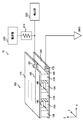
- the 1st structural example of the sensor apparatus 10 which concerns on this embodiment is shown.
- the 2nd structural example of the sensor apparatus 10 which concerns on this embodiment is shown.
- An example of a manufacturing flow of the sensor element 100 according to the present embodiment will be shown.
- the 3rd example of composition of sensor device 10 concerning this embodiment is shown.
- FIG. 1 shows a first configuration example of a sensor device 10 according to this embodiment.
- the sensor device 10 detects whether or not a predetermined pressure is applied to the sensor element 100 from the outside. For example, by arranging the sensor element 100 on a chair, a sofa, a bed or the like, the sensor device 10 functions as a seating sensor and a seating sensor.
- the sensor device 10 includes a sensor element 100, a resistance element 210, a power supply unit 220, and a detection unit 230.
- the sensor element 100 is made of fiber and detects that a predetermined pressure is applied.
- the sensor element 100 includes a first cloth 110, a second cloth 120, a spacer 130, a first electrode 140, a second electrode 150, a first terminal portion 160, a second terminal portion 170, and a second cloth. It has a first connecting portion 180 and a second connecting portion 190.
- the first cloth 110 and the second cloth 120 are formed by weaving or weaving fibers or the like.
- the first cloth 110 and the second cloth 120 are cloth-shaped materials obtained by processing fibers and the like.
- the first cloth 110 and the second cloth 120 face each other. That is, one surface of the first cloth 110 and one surface of the second cloth 120 are formed so as to face each other and be arranged substantially parallel to each other.
- the surface of the first cloth 110 facing the second cloth 120 is referred to as a first surface.
- the surface of the second cloth 120 facing the first cloth 110 is referred to as a second surface.
- the spacer 130 has elasticity or repulsive force and is provided between the first cloth 110 and the second cloth 120.
- the spacer 130 is provided in contact with the first surface of the first cloth 110 and the second surface of the second cloth 120.
- the spacer 130 may be formed, for example, by weaving a part of each of the first cloth 110 and a part of the second cloth 120, or may be formed by weaving instead.
- the length of the spacer 130 in the direction perpendicular to the first surface and the second surface is the distance between the first cloth 110 and the second cloth 120, that is, the first cloth 110 and the second cloth 120. It corresponds to the interval with.
- the direction perpendicular to the first surface and the second surface is the Z direction
- the directions parallel to the first cloth 110 and the second cloth 120 and perpendicular to each other are the X direction and the Y direction. There is.
- the spacer 130 is formed of a non-conductive fiber having elasticity or repulsive force.
- the spacer 130 is formed so as to expand and contract in the Z direction when pressure is applied at least in the Z direction.
- the spacer 130 is formed of a fiber such as rubber, polyurethane or filament.
- the elastic modulus of the spacer 130 can be adjusted according to, for example, the density of fibers, the number of fibers, the material of the fibers, and the like.
- the first electrode 140 is made of a conductive fiber and is provided on the first surface of the first cloth 110.
- the first electrode 140 may be formed by knitting into a part of the first cloth 110, and may be formed by weaving instead.
- One or more first electrodes 140 may be provided on the first cloth 110.
- the second electrode 150 is formed of a conductive fiber, and is provided on the second surface of the second cloth 120 so as to face the first electrode 140 with a space therebetween.
- the second electrode 150 may be formed by knitting into a part of the second cloth 120, and may be formed by weaving instead.
- One or more second electrodes 150 may be provided on the second cloth 120.
- the first electrode 140 and the second electrode 150 are provided in a space between the first cloth 110 and the second cloth 120 where the spacer 130 is not provided. For example, when pressure in the ⁇ Z direction is applied to the first cloth 110, the spacer 130 contracts and the first electrode 140 and the second electrode 150 come into contact with each other and are electrically connected. As described above, the set of the first electrode 140 and the second electrode 150 facing each other functions as a switch that operates with respect to the pressure applied in the Z direction.
- FIG. 1 shows an example in which the first direction is the Y direction.
- a plurality of spacers 130 are provided between the first cloth 110 and the second cloth 120 in a second direction perpendicular to the first direction and parallel to the first cloth 110 and the second cloth 120.
- FIG. 1 shows an example in which the second direction is the X direction and three spacers 130 are arranged in the X direction.
- FIG. 1 illustrates an example in which two pairs of electrodes are arranged in the X direction, one pair of the first electrode 140 and the second electrode 150 facing each other at intervals of two spacers 130 arranged in the X direction. Show.
- the first terminal portion 160 is electrically connected to one or more first electrodes 140.
- the second terminal portion 170 is electrically connected to the one or more second electrodes 150.
- the first terminal portion 160 and the second terminal portion 170 function as input/output terminals of the sensor element 100.
- FIG. 1 shows an example in which one first terminal portion 160 is attached to the surface of the first cloth 110 opposite to the first surface. Further, FIG. 1 shows an example in which one second terminal portion 170 is attached to the second surface of the second cloth 120. At least a part of the first terminal portion 160 and the second terminal portion 170 is, for example, a conductive button or button hook attached to a cloth.
- the button is, for example, a metal fastener such as a snap button.
- the snap button is composed of a set of a removable concave button and a convex button, and one of the concave button and the convex button is sewn to the first cloth 110 and the second cloth 120. Is desirable. Accordingly, one or a plurality of first terminal portions 160 and/or second terminal portions 170 can be easily attached to the sensor element 100. Further, in the cable for electrically connecting the sensor element 100 and an external device or the like, either the concave button or the convex button can be used as a connection terminal.
- the first connection part 180 electrically connects the first electrode 140 and the first terminal part 160.
- the first connecting portion 180 is electrically connected to the plurality of first electrodes 140.
- the first connection part 180 electrically connects the plurality of first electrodes 140 and one first terminal part 160, for example.
- the first connecting portion 180 is provided on the first cloth 110 with a conductive fiber.
- the second connection part 190 electrically connects the second electrode 150 and the second terminal part 170.
- the second connecting portion 190 is electrically connected to the plurality of second electrodes 150.
- the second connection part 190 electrically connects the plurality of second electrodes 150 and one second terminal part 170, for example.
- the second connecting portion 190 is provided on the second cloth 120 with conductive fibers.
- the plurality of first electrodes 140 are electrically connected, and the plurality of second electrodes 150 are also electrically connected.
- only one set of the first electrode 140 and the second electrode 150 among the plurality of sets of the first electrode 140 and the second electrode 150 facing each other is electrically connected, and The second terminal portion 170 switches to the conductive state.
- the first connecting portion 180 and the second connecting portion 190 are, for example, fibers formed by attaching, adsorbing, binding, or printing a conductive material on one or a plurality of places. Further, the first connecting portion 180 and the second connecting portion 190 may be formed by weaving the corresponding first cloth 110 and second cloth 120. Alternatively, they may be formed by weaving. Good.
- first terminal portion 160 and the first connecting portion 180 may be provided in plurality corresponding to the plurality of first electrodes 140.
- the second terminal portion 170 and the second connecting portion 190 may be provided in a plurality corresponding to the plurality of second electrodes 150.
- the plurality of first electrodes 140 may be electrically insulated, and the plurality of second electrodes 150 may also be electrically insulated. In this case, depending on the electrical connection state of each set of the first electrode 140 and the second electrode 150, the conductive state and the non-conductive state of the corresponding second terminal portion 170 and the second connecting portion 190 are switched.
- the resistance element 210 has a predetermined resistance value.
- the resistance element 210 has a resistance value of, for example, several hundreds ⁇ to several tens M ⁇ .
- the resistance element 210 preferably has a resistance value of about several k ⁇ to several M ⁇ .
- One end of the resistance element 210 is electrically connected to one of the first electrode 140 and the second electrode 150 of the sensor element 100.
- FIG. 1 shows an example in which one end of the resistance element 210 is connected to the second electrode 150 via the second terminal portion 170 and the second connection portion 190, and the other end is connected to the ground (GND) of 0V.
- the power supply unit 220 supplies a voltage.
- the power supply unit 220 is a constant voltage source that supplies a predetermined voltage.
- the power supply unit 220 is electrically connected to the other of the first electrode 140 and the second electrode 150, for example. Further, the power supply unit 220 may supply a voltage to the detection unit 230.
- FIG. 1 shows an example in which the power supply unit 220 supplies a predetermined voltage to the first electrode 140 via the first terminal unit 160.
- FIG. 1 above shows an example in which the sensor element 100, the resistance element 210, and the power supply section 220 form a pull-down circuit.
- the voltage between the sensor element 100 and the resistance element 210 becomes a high voltage when the sensor element 100 is in a conductive state and a low voltage when the sensor element 100 is in a non-conductive state.
- the high voltage is substantially equal to the voltage supplied by the power supply unit 220
- the low voltage is substantially equal to the ground voltage.
- the detection unit 230 is electrically connected between the sensor element 100 and the resistance element 210, and detects the value of the voltage drop in the resistance element 210. By detecting the high voltage or the low voltage by the detection unit 230, it is possible to determine whether or not a predetermined pressure is applied to the sensor element 100. For example, when it is determined that a predetermined pressure is applied to the sensor element 100, the detection unit 230 may notify an external device or the like, or may display it on an external display device or the like.
- the detection unit 230 may be an integrated circuit and may have a processor such as a CPU. In this case, the detection unit 230 further has a storage unit, and functions as the detection unit 230 by executing the program stored in the storage unit.
- the sensor device 10 determines whether a predetermined pressure is applied to the sensor element 100 depending on whether the first electrode 140 and the second electrode 150 of the sensor element 100 facing each other are in contact with each other. Determine. Since the predetermined pressure can be determined by the elastic modulus of the spacer 130 and the like, it can be easily designed and manufactured.
- the configuration of FIG. 1 shows an example in which the sensor device 10 constitutes a pull-down circuit, but the configuration is not limited to this. Another configuration example of the sensor device 10 will be described next.
- FIG. 2 shows a second configuration example of the sensor device 10 according to the present embodiment.
- the sensor device 10 of the second configuration example substantially the same operations as those of the sensor device 10 according to this embodiment shown in FIG. 1 are designated by the same reference numerals, and the description thereof will be omitted.
- FIG. 2 shows an example in which the sensor device 10 constitutes a pull-up circuit.
- one end of the resistance element 210 is connected to the first electrode 140 via the first terminal portion 160 and the first connection portion 180. Further, the power supply unit 220 is electrically connected to the other end of the resistance element 210 and supplies a predetermined voltage. Further, the second electrode 150 of the sensor element 100 is connected to the ground via the second terminal portion 170 and the second connecting portion 190. In this case, the voltage between the sensor element 100 and the resistance element 210 is a low voltage when the sensor element 100 is in the conductive state and a high voltage when the sensor element 100 is in the non-conductive state.
- the detection unit 230 can determine whether or not a predetermined pressure is applied to the sensor element 100 by detecting the value of the voltage drop in the resistance element 210.
- the sensor device 10 of the second configuration example like the sensor device 10 of the first configuration example, determines whether the first electrode 140 and the second electrode 150 of the sensor element 100 facing each other are in contact with each other. Then, it is determined whether or not a predetermined pressure is applied to the sensor element 100.
- the sensor element 100 has, for example, the first electrode 140 and the second electrode 150 that extend in the first direction, so that the first cloth 110 and the second cloth 120 are arranged in the first direction. It can have an enlarged detection area. Further, the sensor element 100 is provided with a plurality of sets of opposing first electrodes 140 and second electrodes 150 arranged in the second direction, so that the first cloth 110 and the second cloth 120 are arranged in the second direction. It can have an enlarged detection area. That is, the sensor element 100 can be configured such that most of the surfaces of the first cloth 110 and the second cloth 120 are detection areas. A method of manufacturing such a sensor element 100 will be described below.
- FIG. 3 shows an example of a manufacturing flow of the sensor element 100 according to this embodiment.
- the sensor element 100 can be manufactured by executing the manufacturing flow shown in FIG. Note that FIG. 3 describes an example in which the sensor element 100 is manufactured by using a weaving machine or a knitting machine.
- the fibers to be prepared include a first fiber, a second fiber, a third fiber, and a fourth fiber.
- the first fiber is a non-conductive fiber for forming the first cloth 110.
- the second fiber is a non-conductive fiber for forming the second cloth 120.
- the first fiber and the second fiber may be different types of fibers, and instead, may be substantially the same fiber.
- the third fiber is a non-conductive fiber having elasticity or repulsive force for forming the spacer 130.
- the third fiber is, for example, a fiber such as rubber, polyurethane, or a filament, and is a fiber having elasticity or repulsive force as compared with other fibers.
- the fourth fiber is a conductive fiber for forming the first electrode 140 and the second electrode 150.
- the fourth fiber is, for example, a fiber formed by attaching, adsorbing, binding, or printing a conductive material at one or a plurality of places.
- a base is formed using the prepared fibers (S320).
- the formation of the base body is performed by repeating the formation of each part of the base body.
- the first cloth 110, the second cloth 120, the spacer 130, the first electrode 140, and the second electrode 150 are repeatedly formed part by one in one direction (S322).
- the Y direction in FIG. 1 is the first direction
- the first fiber, the second fiber, the third fiber, and the fourth fiber are woven by a weaving machine along the first direction, or are knitted by a knitting machine, Form a substrate.
- the first cloth 110 is formed by weaving or knitting a plurality of first fibers.
- the second fabric 120 is formed by weaving or knitting a plurality of second fibers.
- the first cloth 110 and the second cloth 120 are formed so as to face each other.
- the spacer 130 is formed by weaving or weaving a plurality of third fibers. Note that, by weaving or knitting the plurality of first fibers and the plurality of third fibers, a part of the spacer 130 connected to the first cloth 110 is formed, and the plurality of second fibers and the plurality of third fibers are formed. By weaving or knitting, a part of the spacer 130 that connects to the second cloth 120 is formed. Thereby, the spacer 130 is provided between the first cloth 110 and the second cloth 120.
- the plurality of first fibers and the plurality of fourth fibers are woven or knitted to form the first cloth 110 and the plurality of first electrodes 140.
- the plurality of second fibers and the plurality of fourth fibers are woven or knitted to form the second cloth 120 and the plurality of second electrodes 150.
- the first electrode 140 and the second electrode 150 are provided in the space between the first cloth 110 and the second cloth 120 where the spacer 130 is not provided.
- the first electrode 140 is provided on the surface of the first cloth 110 facing the second cloth 120
- the second electrode 150 is provided on the surface of the second cloth 120 facing the first cloth 110. It is provided so as to face and away from 140.
- first connecting portion 180 may be formed (S324) and the second connecting portion 190 may be formed (S326) together with the formation of the base body.
- first connecting portion 180 and the second connecting portion 190 are formed using the fourth fiber.
- a plurality of first fibers and a plurality of fourth fibers are woven or woven together with the formation of the first electrode 140 to form a first connection part 180 electrically connected to the plurality of first electrodes 140.
- a plurality of second fibers and a plurality of fourth fibers are woven or knitted to form a second connection portion 190 electrically connected to the plurality of second electrodes 150.
- the formation of such a base body is continued until a predetermined length is formed in the first direction.
- the base body is cut into a predetermined shape (S330). Since the substrate is formed by a knitting machine or a weaving machine, it may be formed including an extra portion such as an end portion. In addition, the sensor element 100 having a complicated shape may be required. In such a case, the substrate of the present embodiment can be cut into a desired shape because a cloth-like substrate is formed of fibers. Further, since the electrodes and the wiring between the electrodes are also formed by using fibers, it is possible to easily cut while preventing the occurrence of electrical connection failure.
- first terminal portion 160 and the second terminal portion 170 are formed (S340).
- the first terminal portion 160 is attached, for example, in contact with the first connecting portion 180 near the end portion of the sensor element 100.
- second terminal portion 170 is attached in contact with the second connection portion 190 near the end of the sensor element 100.
- the base body including the sensor element 100 according to the present embodiment can be formed in one direction without sewing by using a weaving machine, a knitting machine, or the like, similarly to cloth. Therefore, the sensor element 100 can be easily formed by cutting the formed base and attaching the terminals. Further, since the sensor element 100 is formed of a plurality of fibers, it can be freely bent and can be inserted into a cushion, a cushion, a pillow, or the like. The sensor element 100 can also be used as a cover for a cushion, cushion, pillow, or the like. That is, even in a chair, a sofa, a bed or the like having no sensor function, a seating sensor can be configured by disposing a cushion or the like provided with the sensor element 100.
- the sensor element 100 may be directly attached to a chair, a sofa, a bed or the like to form a seating sensor. Further, the sensor element 100 may be used as a sheet, a cover or the like. With such a sensor element 100, it can be used not only as a seat on the bed but also as a floor sensor. In this case, the sensor element 100 is preferably provided with the first connecting portion 180 and the second connecting portion 190 for each of the plurality of regions and configured to detect whether or not the pressure is applied to each of the plurality of regions. ..
- the sensor element 100 is appropriately provided on the first cloth 110 and/or the second cloth 120 and the like with a material such as cloth, cotton, fiber, wool, feathers, paper, etc., depending on a place to be attached, an object, or the like. It goes without saying that it is okay to be done.
- the first electrode 140 and the second electrode 150 facing the spacer 130 are provided between a pair of cloths such as the first cloth 110 and the second cloth 120.
- the above example has been described, but the present invention is not limited to this.
- the sensor element 100 may include multiple sets of fabrics. For example, a configuration in which a plurality of sensor elements 100 described in FIG. 1 are stacked may be used. Such an example will be described below.
- FIG. 4 shows a third configuration example of the sensor device 10 according to the present embodiment.
- the sensor device 10 of the third configuration example includes a plurality of sensor elements 100.
- the remaining plurality of sensor elements 100 are stacked in the direction perpendicular to the first cloth 110 and the second cloth 120 of the one sensor element 100.
- the plurality of sensor elements 100 stacked in the Z direction function as one sensor element 400.
- the sensor device 10 of the third configuration example includes a plurality of resistance elements 210 corresponding to the plurality of sensor elements 100.
- a pull-up circuit and/or a pull-down circuit is configured for each sensor element 100.
- the plurality of resistance elements 210 are provided respectively corresponding to the plurality of sensor elements 100, and one end is connected to either one of the first electrode 140 and the second electrode 150 of each sensor element 100.
- the power supply unit 220 is electrically connected to the other of the first electrode 140 and the second electrode 150 of each sensor element 100 or the other end of the resistance element 210, and supplies a predetermined voltage. To do.
- a plurality of power supply units 220 may be provided. When a plurality of power supply units 220 are provided, each of the plurality of power supply units 220 may supply different voltages.
- the detection unit 230 is electrically connected between each sensor element 100 and the corresponding resistance element 210, and detects the voltage drop value in each of the plurality of resistance elements 210.
- the detection unit 230 may acquire the detection results of the plurality of sensor elements 100 and determine the magnitude of the pressure applied to the sensor element 400.
- each of the plurality of sensor elements 100 includes a spacer 130 having substantially the same elastic modulus. Accordingly, the constant pressure detected by the entire sensor element 400 can be adjusted by the number of sensor elements 100. In this case, when the pressure applied to the sensor element 400 exceeds a certain pressure, the plurality of sensor elements 100 become conductive. Therefore, the detection unit 230 may determine the magnitude of the pressure applied to the sensor element 400 based on the detection result of one sensor element 100. Further, in such a case, the pull-up circuit and/or the pull-down circuit may not be configured for each sensor element 100, and may be configured for only one sensor element 100, for example.
- At least one sensor element 100 may include a spacer 130 having an elastic modulus different from that of the spacers 130 provided on the other sensor elements 100.
- the sensor element 100 having the spacer 130 having a small elastic modulus among the plurality of sensor elements 100 becomes conductive first. That is, in accordance with the pressure applied to the sensor element 400, the sensor element 100 including the spacer 130 having a small elastic modulus is sequentially connected to the sensor element 100 including the spacer 130 having a large elastic modulus.
- the sensor element 400 can function as a pressure sensor because the different sensor elements 100 are in a conductive state with respect to different pressures.
- the spacers 130 provided in the plurality of sensor elements 100 have different elastic moduli, and it is more preferable that all the spacers 130 have different elastic moduli.
- the elastic modulus of the spacer 130 can be easily adjusted by the density, number, and material of the third fibers forming the spacer 130.
- the present invention is not limited to this.
- the distance between the first cloth 110 and the second cloth 120 that is, the length of the spacer 130 in the Z direction may be different.
- the elastic modulus of the spacer 130 is constant, if the length of the spacer 130 in the Z direction is different, the amount of deformation of the spacer 130 with respect to the same pressure will be different. Therefore, according to the pressure applied to the sensor element 400, the sensor element 100 having the shorter length in the Z direction of the spacer 130 among the plurality of sensor elements 100 becomes conductive in order.
- At least one sensor element 100 of the plurality of sensor elements 100 has the first cloth 110 and the second cloth 120 provided on the other sensor elements 100 at a distance different from the distance between the first cloth 110 and the second cloth 120.
- One cloth 110 and a second cloth 120 may be provided.
- the sensor element 400 may be provided with a plurality of sensor elements 100 in which the elastic modulus of the spacer 130 and the length of the spacer 130 in the Z direction are different from each other. As a result, the degree of freedom in designing the magnitude of pressure that can be detected by the sensor element 400 can be improved.
- a plurality of sensor elements 100 are manufactured according to the manufacturing flow of the sensor element 100 described in FIG. 3, and then the sensor element 100 is in a direction perpendicular to the first cloth 110 and the second cloth 120 of the one sensor element 100. Can be formed by stacking the remaining plural sensor elements 100. Therefore, like the sensor element 100, the sensor element 400 can be easily formed. That is, according to the present embodiment, it is possible to simply configure the sensor device 10 that functions not only as a seating sensor and a landing sensor but also as a pressure sensor.
- the sensor device 10 can reduce the power consumption to about the power consumed by the current flowing through the resistance element 210. Therefore, for example, the power supply unit 220 may be a battery or the like.
- the present invention has been described above using the embodiments, the technical scope of the present invention is not limited to the scope described in the above embodiments, and various modifications and changes are possible within the scope of the gist thereof. is there.
- the specific embodiment of the distribution/integration of the device is not limited to the above-described embodiment, and all or a part thereof may be functionally or physically distributed/integrated in arbitrary units to be configured.
- You can Further, a new embodiment that occurs due to an arbitrary combination of a plurality of embodiments is also included in the embodiments of the present invention. The effect of the new embodiment produced by the combination also has the effect of the original embodiment.
- sensor device 100 sensor element 110 first cloth 120 second cloth 130 spacer 140 first electrode 150 second electrode 160 first terminal portion 170 second terminal portion 180 first connecting portion 190 second connecting portion 210 resistance element 220 Power supply unit 230 Detection unit
Landscapes
- Physics & Mathematics (AREA)
- General Physics & Mathematics (AREA)
- Force Measurement Appropriate To Specific Purposes (AREA)
Priority Applications (2)
| Application Number | Priority Date | Filing Date | Title |
|---|---|---|---|
| JP2021503368A JPWO2020179054A1 (https=) | 2019-03-07 | 2019-03-07 | |
| PCT/JP2019/009073 WO2020179054A1 (ja) | 2019-03-07 | 2019-03-07 | センサ素子、センサ装置、およびセンサ素子の製造方法 |
Applications Claiming Priority (1)
| Application Number | Priority Date | Filing Date | Title |
|---|---|---|---|
| PCT/JP2019/009073 WO2020179054A1 (ja) | 2019-03-07 | 2019-03-07 | センサ素子、センサ装置、およびセンサ素子の製造方法 |
Publications (1)
| Publication Number | Publication Date |
|---|---|
| WO2020179054A1 true WO2020179054A1 (ja) | 2020-09-10 |
Family
ID=72338505
Family Applications (1)
| Application Number | Title | Priority Date | Filing Date |
|---|---|---|---|
| PCT/JP2019/009073 Ceased WO2020179054A1 (ja) | 2019-03-07 | 2019-03-07 | センサ素子、センサ装置、およびセンサ素子の製造方法 |
Country Status (2)
| Country | Link |
|---|---|
| JP (1) | JPWO2020179054A1 (https=) |
| WO (1) | WO2020179054A1 (https=) |
Citations (4)
| Publication number | Priority date | Publication date | Assignee | Title |
|---|---|---|---|---|
| JPH0566166A (ja) * | 1991-09-06 | 1993-03-19 | Alps Electric Co Ltd | 座席用検知装置 |
| JP2008249409A (ja) * | 2007-03-29 | 2008-10-16 | Fukui Prefecture | 感圧用繊維構造体 |
| WO2017141010A1 (en) * | 2016-02-17 | 2017-08-24 | The Helping Hand Company (Ledbury) Limited | Support evaluation device |
| JP2018019762A (ja) * | 2016-08-01 | 2018-02-08 | 帝人株式会社 | センサシーツ |
Family Cites Families (9)
| Publication number | Priority date | Publication date | Assignee | Title |
|---|---|---|---|---|
| US6369804B1 (en) * | 1998-09-26 | 2002-04-09 | Eleksen Limited | Detector constructed from fabric having non-uniform conductivity |
| US6504531B1 (en) * | 1999-05-20 | 2003-01-07 | Eleksen Limited | Detecting mechanical interactions |
| JP4780058B2 (ja) * | 2007-08-09 | 2011-09-28 | 株式会社日本マイクロシステム | 感圧センサ |
| WO2009030067A1 (en) * | 2007-09-04 | 2009-03-12 | Chang-Ming Yang | Cloth capable of forming electronic components |
| US9271665B2 (en) * | 2011-05-20 | 2016-03-01 | The Regents Of The University Of California | Fabric-based pressure sensor arrays and methods for data analysis |
| US8966997B2 (en) * | 2011-10-12 | 2015-03-03 | Stryker Corporation | Pressure sensing mat |
| JP3183657U (ja) * | 2013-03-13 | 2013-05-30 | 金鼎聯合科技纖維股▲分▼有限公司 | 織物圧力スイッチ |
| JP2017026594A (ja) * | 2015-07-17 | 2017-02-02 | 帝人株式会社 | 布帛状センサおよびこれを含むデバイス |
| DE102017100791B4 (de) * | 2017-01-17 | 2018-09-06 | Pilz Gmbh & Co. Kg | Mehrschichtiger, taktiler Sensor mit Befestigungsmittel |
-
2019
- 2019-03-07 WO PCT/JP2019/009073 patent/WO2020179054A1/ja not_active Ceased
- 2019-03-07 JP JP2021503368A patent/JPWO2020179054A1/ja active Pending
Patent Citations (4)
| Publication number | Priority date | Publication date | Assignee | Title |
|---|---|---|---|---|
| JPH0566166A (ja) * | 1991-09-06 | 1993-03-19 | Alps Electric Co Ltd | 座席用検知装置 |
| JP2008249409A (ja) * | 2007-03-29 | 2008-10-16 | Fukui Prefecture | 感圧用繊維構造体 |
| WO2017141010A1 (en) * | 2016-02-17 | 2017-08-24 | The Helping Hand Company (Ledbury) Limited | Support evaluation device |
| JP2018019762A (ja) * | 2016-08-01 | 2018-02-08 | 帝人株式会社 | センサシーツ |
Also Published As
| Publication number | Publication date |
|---|---|
| JPWO2020179054A1 (https=) | 2020-09-10 |
Similar Documents
| Publication | Publication Date | Title |
|---|---|---|
| US6714117B2 (en) | Detector constructed from fabric | |
| US9448127B2 (en) | Device for measuring pressure from a flexible, pliable, and/or extensible object made from a textile material comprising a measurement device | |
| JP5467322B2 (ja) | 感圧シート | |
| CN108135362B (zh) | 压力感测椅 | |
| CN111534899B (zh) | 织造织物中的导电信号路径 | |
| JP4273233B2 (ja) | 感圧センサーシート | |
| BR0109801A (pt) | Produto textil sensìvel à pressão condutora | |
| JP4565109B2 (ja) | 感圧用繊維構造体 | |
| ATE371920T1 (de) | Gefüge | |
| JP2016031269A (ja) | 体圧分布測定装置 | |
| CN109959474A (zh) | 具有集成感测和控制元件的多功能纺织品 | |
| KR20160118110A (ko) | 복합센서 | |
| US11620881B2 (en) | Haptic feedback fiber body, haptic feedback fabric and wearable device | |
| KR20180117893A (ko) | 압력 센서 | |
| JP5659349B2 (ja) | 引張変形検知布 | |
| JP6671910B2 (ja) | 静電容量式タッチセンサ | |
| WO2019167744A1 (ja) | センサ用電極およびそれを用いた面状センサ | |
| JP4740129B2 (ja) | 比例入力インタフェース | |
| WO2020179054A1 (ja) | センサ素子、センサ装置、およびセンサ素子の製造方法 | |
| JP6985586B2 (ja) | 乗物用シート | |
| JP6829365B2 (ja) | 圧力センサ、圧力センサの製造方法、ベッド装置及び自動車用シート | |
| JP2020008438A (ja) | 感圧センサ及びその製造方法 | |
| JP2020177015A (ja) | 感圧センサ | |
| CN113383219A (zh) | 压敏传感器 | |
| KR20170081482A (ko) | 압력 감지 의자 |
Legal Events
| Date | Code | Title | Description |
|---|---|---|---|
| 121 | Ep: the epo has been informed by wipo that ep was designated in this application |
Ref document number: 19917778 Country of ref document: EP Kind code of ref document: A1 |
|
| ENP | Entry into the national phase |
Ref document number: 2021503368 Country of ref document: JP Kind code of ref document: A |
|
| NENP | Non-entry into the national phase |
Ref country code: DE |
|
| 122 | Ep: pct application non-entry in european phase |
Ref document number: 19917778 Country of ref document: EP Kind code of ref document: A1 |