WO2020178939A1 - Medical treatment tool - Google Patents
Medical treatment tool Download PDFInfo
- Publication number
- WO2020178939A1 WO2020178939A1 PCT/JP2019/008364 JP2019008364W WO2020178939A1 WO 2020178939 A1 WO2020178939 A1 WO 2020178939A1 JP 2019008364 W JP2019008364 W JP 2019008364W WO 2020178939 A1 WO2020178939 A1 WO 2020178939A1
- Authority
- WO
- WIPO (PCT)
- Prior art keywords
- arm
- conductor
- support
- medical treatment
- cover
- Prior art date
Links
Images


Classifications
-
- A—HUMAN NECESSITIES
- A61—MEDICAL OR VETERINARY SCIENCE; HYGIENE
- A61B—DIAGNOSIS; SURGERY; IDENTIFICATION
- A61B18/00—Surgical instruments, devices or methods for transferring non-mechanical forms of energy to or from the body
- A61B18/04—Surgical instruments, devices or methods for transferring non-mechanical forms of energy to or from the body by heating
- A61B18/08—Surgical instruments, devices or methods for transferring non-mechanical forms of energy to or from the body by heating by means of electrically-heated probes
- A61B18/082—Probes or electrodes therefor
- A61B18/085—Forceps, scissors
-
- A—HUMAN NECESSITIES
- A61—MEDICAL OR VETERINARY SCIENCE; HYGIENE
- A61B—DIAGNOSIS; SURGERY; IDENTIFICATION
- A61B18/00—Surgical instruments, devices or methods for transferring non-mechanical forms of energy to or from the body
- A61B18/04—Surgical instruments, devices or methods for transferring non-mechanical forms of energy to or from the body by heating
- A61B18/12—Surgical instruments, devices or methods for transferring non-mechanical forms of energy to or from the body by heating by passing a current through the tissue to be heated, e.g. high-frequency current
- A61B18/14—Probes or electrodes therefor
- A61B18/1442—Probes having pivoting end effectors, e.g. forceps
-
- A—HUMAN NECESSITIES
- A61—MEDICAL OR VETERINARY SCIENCE; HYGIENE
- A61B—DIAGNOSIS; SURGERY; IDENTIFICATION
- A61B18/00—Surgical instruments, devices or methods for transferring non-mechanical forms of energy to or from the body
- A61B18/04—Surgical instruments, devices or methods for transferring non-mechanical forms of energy to or from the body by heating
- A61B18/12—Surgical instruments, devices or methods for transferring non-mechanical forms of energy to or from the body by heating by passing a current through the tissue to be heated, e.g. high-frequency current
- A61B18/1206—Generators therefor
-
- A—HUMAN NECESSITIES
- A61—MEDICAL OR VETERINARY SCIENCE; HYGIENE
- A61B—DIAGNOSIS; SURGERY; IDENTIFICATION
- A61B18/00—Surgical instruments, devices or methods for transferring non-mechanical forms of energy to or from the body
- A61B2018/00053—Mechanical features of the instrument of device
- A61B2018/00059—Material properties
- A61B2018/00071—Electrical conductivity
- A61B2018/00077—Electrical conductivity high, i.e. electrically conducting
-
- A—HUMAN NECESSITIES
- A61—MEDICAL OR VETERINARY SCIENCE; HYGIENE
- A61B—DIAGNOSIS; SURGERY; IDENTIFICATION
- A61B18/00—Surgical instruments, devices or methods for transferring non-mechanical forms of energy to or from the body
- A61B2018/00053—Mechanical features of the instrument of device
- A61B2018/00107—Coatings on the energy applicator
- A61B2018/00136—Coatings on the energy applicator with polymer
-
- A—HUMAN NECESSITIES
- A61—MEDICAL OR VETERINARY SCIENCE; HYGIENE
- A61B—DIAGNOSIS; SURGERY; IDENTIFICATION
- A61B18/00—Surgical instruments, devices or methods for transferring non-mechanical forms of energy to or from the body
- A61B2018/00571—Surgical instruments, devices or methods for transferring non-mechanical forms of energy to or from the body for achieving a particular surgical effect
- A61B2018/00577—Ablation
-
- A—HUMAN NECESSITIES
- A61—MEDICAL OR VETERINARY SCIENCE; HYGIENE
- A61B—DIAGNOSIS; SURGERY; IDENTIFICATION
- A61B18/00—Surgical instruments, devices or methods for transferring non-mechanical forms of energy to or from the body
- A61B2018/00571—Surgical instruments, devices or methods for transferring non-mechanical forms of energy to or from the body for achieving a particular surgical effect
- A61B2018/00589—Coagulation
-
- A—HUMAN NECESSITIES
- A61—MEDICAL OR VETERINARY SCIENCE; HYGIENE
- A61B—DIAGNOSIS; SURGERY; IDENTIFICATION
- A61B18/00—Surgical instruments, devices or methods for transferring non-mechanical forms of energy to or from the body
- A61B2018/00571—Surgical instruments, devices or methods for transferring non-mechanical forms of energy to or from the body for achieving a particular surgical effect
- A61B2018/00607—Coagulation and cutting with the same instrument
-
- A—HUMAN NECESSITIES
- A61—MEDICAL OR VETERINARY SCIENCE; HYGIENE
- A61B—DIAGNOSIS; SURGERY; IDENTIFICATION
- A61B18/00—Surgical instruments, devices or methods for transferring non-mechanical forms of energy to or from the body
- A61B18/04—Surgical instruments, devices or methods for transferring non-mechanical forms of energy to or from the body by heating
- A61B18/12—Surgical instruments, devices or methods for transferring non-mechanical forms of energy to or from the body by heating by passing a current through the tissue to be heated, e.g. high-frequency current
- A61B18/1206—Generators therefor
- A61B2018/1246—Generators therefor characterised by the output polarity
- A61B2018/126—Generators therefor characterised by the output polarity bipolar
-
- A—HUMAN NECESSITIES
- A61—MEDICAL OR VETERINARY SCIENCE; HYGIENE
- A61B—DIAGNOSIS; SURGERY; IDENTIFICATION
- A61B18/00—Surgical instruments, devices or methods for transferring non-mechanical forms of energy to or from the body
- A61B18/04—Surgical instruments, devices or methods for transferring non-mechanical forms of energy to or from the body by heating
- A61B18/12—Surgical instruments, devices or methods for transferring non-mechanical forms of energy to or from the body by heating by passing a current through the tissue to be heated, e.g. high-frequency current
- A61B18/14—Probes or electrodes therefor
- A61B18/1442—Probes having pivoting end effectors, e.g. forceps
- A61B2018/1462—Tweezers
-
- A—HUMAN NECESSITIES
- A61—MEDICAL OR VETERINARY SCIENCE; HYGIENE
- A61B—DIAGNOSIS; SURGERY; IDENTIFICATION
- A61B18/00—Surgical instruments, devices or methods for transferring non-mechanical forms of energy to or from the body
- A61B18/04—Surgical instruments, devices or methods for transferring non-mechanical forms of energy to or from the body by heating
- A61B18/12—Surgical instruments, devices or methods for transferring non-mechanical forms of energy to or from the body by heating by passing a current through the tissue to be heated, e.g. high-frequency current
- A61B18/14—Probes or electrodes therefor
- A61B2018/1467—Probes or electrodes therefor using more than two electrodes on a single probe
Definitions
- the present disclosure relates to a medical treatment tool.
- the weight of the conventional bipolar tweezers is relatively large because the skeleton of the arm (that is, the grip) is made of metal that also serves as a conductor. Further, since the arm is formed to have a constant size in order to maintain rigidity, the arm may be difficult to grip depending on the size of the user's hand. As described above, the conventional bipolar tweezers impose a heavy burden on the user.
- a medical treatment tool that can be lightweight and compact while maintaining rigidity.
- One aspect of the present disclosure is a first arm and a first arm that have a first end and a second end, respectively, and the first ends are connected to each other so that the distance between the second ends can be adjusted. It is a medical treatment tool provided with two arms. Each of the first arm and the second arm extends from the first end to the second end, and is mainly composed of a conductor exposed at the second end and a composite material of a resin and a reinforcing material. It has a support body extending along the conductor and a cover covering the conductor and the support body.
- the rigidity of the first arm and the second arm is maintained by supporting the conductor with the support made of the composite material. Need not be configured with.
- the composite material used for the support is lighter than metal.
- the first arm and the second arm are reduced in weight and size.
- the cover can increase the degree of freedom in designing the color, shape, etc. of the medical treatment tool.
- the cover may include a resin as a main component.
- the support body of the first arm may be arranged on the opposite side of the conductor from the second arm.
- the support body of the second arm may be arranged on the opposite side of the conductor from the first arm.
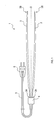
- FIG. 1 is a schematic diagram of a medical treatment tool according to an embodiment.
- FIG. 2 is a schematic partially enlarged perspective view near the second end of the first arm in the medical treatment tool of FIG. 1.
- 3A is a schematic cross-sectional view taken along the line IIIA-IIIA of FIG. 2
- FIG. 3B is a schematic cross-sectional view taken along the line IIIB-IIIB of FIG. 3A.
- the medical treatment tool 1 shown in FIG. 1 is a treatment tool for performing incision, coagulation, or the like of a living tissue by a high frequency voltage.
- the medical treatment tool 1 includes a first arm 2, a second arm 3, a connecting portion 4, a cord 5, and a plug 6.
- the medical treatment tool 1 is an electric knife having a bipolar electrode (so-called bipolar tweezers).
- the first arm 2 is a plate-shaped or rod-shaped member that has a first end 2A and a second end 2B and extends from the first end 2A to the second end 2B.
- the second arm 3 is a plate-shaped or rod-shaped member having a first end portion 3A and a second end portion 3B and extending from the first end portion 3A to the second end portion 3B.
- the first end portions 2A and 3A are connected to each other by the connecting portion 4 so that the distance between the second end portions 2B and 3B can be adjusted. That is, the first arm 2 and the second arm 3 form a tweezers that opens and closes with the connecting portion 4 as a fulcrum.
- the second end 2B of the first arm 2 and the second end 3B of the second arm 3 are separated from each other when not in use and close to each other when in use (that is, when the procedure is executed). However, during use, the second ends 2B and 3B of the first arm 2 and the second arm 3 do not contact each other.
- the first arm 2 has a conductor 21, a support 22, and a cover 23.
- the conductor 21 is a rod-shaped member that extends from the first end 2A to the second end 2B of the first arm 2. A current is supplied to the conductor 21 from a cord 5 described later.
- the conductor 21 is exposed at the second end 2B of the first arm 2. That is, the conductor 21 has a tip portion 21A that is not covered by the support body 22 and the cover 23 described later.
- the tip portion 21A makes contact with living tissue and constitutes an action point for applying a high frequency voltage.
- the material of the conductor 21 for example, a metal such as copper, gold, aluminum, platinum, molybdenum, nickel, tungsten, or chromium can be used.
- the tip 21A of the conductor 21 may be plated with a noble metal.
- the material may be changed between the tip portion 21A of the conductor 21 and the other portion (that is, the portion covered by the cover 23).
- the support 22 is a layer whose main component is a composite material (so-called reinforced plastic) of resin (that is, matrix) and reinforcement material.
- the "main component” is a component contained in 90% by mass or more.
- the resin used for the composite material is not particularly limited, and a thermosetting resin or a thermoplastic resin can be used.
- the reinforcing material used in the composite material include fibers and granules.
- fibers used in the composite material include glass fibers and carbon fibers.
- Examples of the shape of the particles include spheres, polyhedra, and cylinders.
- the support 22 extends along the conductor 21 from the first end 2A to the second end 2B.
- the support 22 may be divided into a plurality of portions in the longitudinal direction of the first arm 2. That is, the first arm 2 may have a region where the support 22 does not exist in the portion other than the second end portion 2B.
- the support 22 is arranged so as to be superposed on the surface of the conductor 21, and is in contact with the surface of the conductor 21.
- the support 22 covers a part of the surface of the conductor 21 in the circumferential direction.
- the support body 22 is arranged on the side opposite to the second arm 3 with respect to the conductor 21 (that is, the side in which the tweezers open).
- the support 22 is not superposed on the first end 21A of the conductor 21.
- the support 22 is covered with a cover 23 described later and is not exposed to the outside at the second end 2B of the first arm 2. Therefore, the support 22 does not contact the living tissue.
- the cover 23 is a member that covers the conductor 21 and the support 22.
- the cover 23 covers the entire support 22 and the portion of the conductor 21 other than the tip portion 21A.
- the cover 23 constitutes a gripping part that the user grips.
- the material of the cover 23 is not particularly limited.
- the cover 23 is preferably made of a resin such as polyamide, polyethylene, or polyether ether ketone (PEEK) as a main component.
- PEEK polyether ether ketone
- a composite material containing a conductive reinforcing material for example, fiber reinforced containing carbon fibers such as carbon nanotubes
- the support 22 can be formed of plastic.
- the weight of the first arm 2 can be further reduced. Further, since the cover 23 is easily molded, the productivity of the first arm 2 is improved.
- the conductor 21 projects from the end face formed by the support 22 and the cover 23, but this configuration is an example.
- the support 22 and the cover 23 may be continuously tapered toward the tip portion 21A of the conductor 21. Further, only the cover 23 may be continuously reduced in diameter toward the tip portion 21A.
- the second arm 3 has a conductor 21 similar to the first arm 2, a support 22, and a cover 23. However, in the second arm 3, the support 22 is arranged on the opposite side of the conductor 21 from the first arm 2.
- the shape of the second arm 3 is perpendicular to the opposite direction of the first arm 2 and the second arm 3, and the distances from the tip portions 21A of the first arm 2 and the second arm 3 are equal to each other.
- the shape is symmetrical to the first arm 2 with reference to (see FIG. 1).
- the first arm 2 and the second arm 3 can be manufactured by the following procedure, for example. First, the composite material sheet forming the support 22 is overlaid on the conductor 21. Further, the two resin sheets forming the cover 23 are superposed so as to sandwich the conductor 21 and the composite material sheet. The first arm 2 and the second arm 3 are obtained by pressing each member while heating the laminated body.
- a joined body of the conductor 21 and the support body 22 may be produced, and the joined body may be covered with the cover 23.
- Specific methods of covering with the cover 23 include spraying a resin onto the bonded body, insert molding of the resin onto the bonded body, coating a shrinkable tube onto the bonded body, and the like.
- the connecting portion 4 is attached to the first end 2A of the first arm 2 and the first end 3A of the second arm 3.
- the connecting part 4 constitutes a fulcrum of the tweezers composed of the first arm 2 and the second arm 3. Further, the cord 5 is drawn into the connecting portion 4.
- the conductor 21 of the first arm 2 and the conductor 21 of the second arm 3 are insulated from each other in the connecting portion 4.
- the cord 5 is a bipolar cord having two electric wires. Each electric wire is electrically connected to the conductor 21 of the first arm 2 and the conductor 21 of the second arm 3 in the connecting portion 4.
- the plug 6 is electrically connected to the cord 5.
- the plug 6 is connected to a high frequency current generator (not shown).
- the high-frequency current generated by the high-frequency current generator flows through the cord 5 to the conductor 21 of the first arm 2.
- the high-frequency current flowing through the conductor 21 of the first arm 2 flows from the tip portion 21A of the conductor 21 to the tip portion 21A of the conductor 21 of the second arm 3 via the biological tissue, and returns to the high-frequency current generator.
- a current may flow from the conductor 21 of the second arm 3 to the conductor 21 of the first arm 2.
- the support 22 of the first arm 2 is arranged on the opposite side of the conductor 21 from the second arm 3, and the support 22 of the second arm 3 is on the opposite side of the conductor 21 from the first arm 2.
- the conductors 21 of the first arm 2 and the second arm 3 that are opened and closed are supported by the support 22 from the outside. Therefore, the rigidity of the first arm 2 and the second arm 3 can be improved.
- the support 22 of the first arm 2 does not necessarily have to be arranged on the side opposite to the second arm 3 with respect to the conductor 21.
- the support 22 of the second arm 3 does not necessarily have to be arranged on the opposite side of the conductor 21 from the first arm 2.
- the support 22 may cover the surface of the conductor 21 over the entire circumferential direction (that is, so as to wrap the conductor 21). Furthermore, the support 22 does not necessarily have to contact the conductor 21. That is, another member (for example, a part of the cover 23) may be arranged between the support 22 and the conductor 21.
Landscapes
- Health & Medical Sciences (AREA)
- Surgery (AREA)
- Engineering & Computer Science (AREA)
- Life Sciences & Earth Sciences (AREA)
- Biomedical Technology (AREA)
- Otolaryngology (AREA)
- Nuclear Medicine, Radiotherapy & Molecular Imaging (AREA)
- Plasma & Fusion (AREA)
- Physics & Mathematics (AREA)
- Heart & Thoracic Surgery (AREA)
- Medical Informatics (AREA)
- Molecular Biology (AREA)
- Animal Behavior & Ethology (AREA)
- General Health & Medical Sciences (AREA)
- Public Health (AREA)
- Veterinary Medicine (AREA)
- Surgical Instruments (AREA)
Abstract
An embodiment of the present disclosure is a medical treatment tool provided with a first arm and a second arm each having a first end part and a second end part, in which the first end parts are connected to each other so that the distance between the second end parts can be adjusted. The first arm and the second arm each have a conductor which extends from the first end part to the second end part and is exposed in the second end part, a support body which has a composite of a resin and a reinforcing material as the main component thereof and which extends along the conductor, and a cover for covering the conductor and the support body.
Description
本開示は、医療用処置具に関する。
The present disclosure relates to a medical treatment tool.
被処置物である生体組織に高周波電圧を印加することで、生体組織を切開したり、凝固させたりする医療用処置具が知られている。このような医療用処置具の1種として、被処置物において2つの作用点に電圧を印加するバイポーラピンセットがある(特許文献1参照)。
There is known a medical treatment tool that incises or coagulates a living tissue by applying a high-frequency voltage to the living tissue that is the object to be treated. As one type of such a medical treatment tool, there is a bipolar tweezers that applies a voltage to two points of action on the object to be treated (see Patent Document 1).
従来のバイポーラピンセットは、アーム(つまり把持部)の骨格が導体を兼ねた金属で形成されているため、重量が比較的大きい。また、剛性を保つために、アームが一定の大きさに形成されているため、使用者の手のサイズによってはアームが把持しにくいことがある。このように、従来のバイポーラピンセットは、使用者への負担が大きい。
The weight of the conventional bipolar tweezers is relatively large because the skeleton of the arm (that is, the grip) is made of metal that also serves as a conductor. Further, since the arm is formed to have a constant size in order to maintain rigidity, the arm may be difficult to grip depending on the size of the user's hand. As described above, the conventional bipolar tweezers impose a heavy burden on the user.
本開示の一局面は、剛性を維持しつつ、軽量化及び小型化が可能な医療用処置具を提供することが好ましい。
According to one aspect of the present disclosure, it is preferable to provide a medical treatment tool that can be lightweight and compact while maintaining rigidity.
本開示の一態様は、それぞれ第1端部と第2端部とを有すると共に、第2端部同士の距離が調整可能なように第1端部同士が互いに連結された第1アーム及び第2アームを備える医療用処置具である。第1アーム及び第2アームは、それぞれ、第1端部から第2端部まで延伸すると共に、第2端部において露出する導体と、樹脂と強化材との複合材を主成分とすると共に、導体に沿って延伸する支持体と、導体及び支持体を被覆するカバーと、を有する。
One aspect of the present disclosure is a first arm and a first arm that have a first end and a second end, respectively, and the first ends are connected to each other so that the distance between the second ends can be adjusted. It is a medical treatment tool provided with two arms. Each of the first arm and the second arm extends from the first end to the second end, and is mainly composed of a conductor exposed at the second end and a composite material of a resin and a reinforcing material. It has a support body extending along the conductor and a cover covering the conductor and the support body.
このような構成によれば、複合材で構成される支持体によって導体を支持することで第1アーム及び第2アームの剛性が維持されるため、従来のように一定の大きさの骨格を金属で構成する必要がない。また、支持体に用いられる複合材は、金属よりも軽量である。その結果、第1アーム及び第2アームが軽量化及び小型化される。また、カバーによって、医療用処置具の色、形状等の設計自由度を高めることができる。
According to this structure, the rigidity of the first arm and the second arm is maintained by supporting the conductor with the support made of the composite material. Need not be configured with. Also, the composite material used for the support is lighter than metal. As a result, the first arm and the second arm are reduced in weight and size. In addition, the cover can increase the degree of freedom in designing the color, shape, etc. of the medical treatment tool.
本開示の一態様では、カバーは樹脂を主成分としてもよい。このような構成によれば、第1アーム及び第2アームをより軽量化することができる。また、第1アーム及び第2アームの生産性を向上することができる。
In one aspect of the present disclosure, the cover may include a resin as a main component. With such a configuration, it is possible to further reduce the weight of the first arm and the second arm. In addition, the productivity of the first arm and the second arm can be improved.
本開示の一態様では、第1アームの支持体は、導体に対し第2アームとは反対側に配置されてもよい。第2アームの支持体は、導体に対し第1アームとは反対側に配置されてもよい。このような構成によれば、開閉動作をする第1アーム及び第2アームにおいて、それぞれの導体を外側から支持体で支えられるので、第1アーム及び第2アームの剛性を向上できる。
In an aspect of the present disclosure, the support body of the first arm may be arranged on the opposite side of the conductor from the second arm. The support body of the second arm may be arranged on the opposite side of the conductor from the first arm. According to such a configuration, in the first arm and the second arm that open and close, the respective conductors are supported by the support from the outside, so that the rigidity of the first arm and the second arm can be improved.
1…医療用処置具、2…第1アーム、2A…第1端部、2B…第2端部、3…第2アーム、3A…第1端部、3B…第2端部、4…連結部、5…コード、6…差し込みプラグ、21…導体、21A…先端部、22…支持体、23…カバー。
1 ... Medical treatment tool, 2 ... 1st arm, 2A ... 1st end, 2B ... 2nd end, 3 ... 2nd arm, 3A ... 1st end, 3B ... 2nd end, 4 ... Connect Part, 5... Cord, 6... Insert plug, 21... Conductor, 21A... Tip part, 22... Support body, 23... Cover.
以下、本開示が適用された実施形態について、図面を用いて説明する。
Hereinafter, embodiments to which the present disclosure is applied will be described with reference to the drawings.
[1.第1実施形態]
[1-1.構成]
図1に示す医療用処置具1は、高周波電圧によって、生体組織の切開、凝固等を行うための処置具である。 [1. First Embodiment]
[1-1. Constitution]
Themedical treatment tool 1 shown in FIG. 1 is a treatment tool for performing incision, coagulation, or the like of a living tissue by a high frequency voltage.
[1-1.構成]
図1に示す医療用処置具1は、高周波電圧によって、生体組織の切開、凝固等を行うための処置具である。 [1. First Embodiment]
[1-1. Constitution]
The
医療用処置具1は、第1アーム2と、第2アーム3と、連結部4と、コード5と、差し込みプラグ6とを備える。医療用処置具1は、バイポーラ電極を有する電気メス(いわゆるバイポーラピンセット)である。
The medical treatment tool 1 includes a first arm 2, a second arm 3, a connecting portion 4, a cord 5, and a plug 6. The medical treatment tool 1 is an electric knife having a bipolar electrode (so-called bipolar tweezers).
<アーム>
第1アーム2は、第1端部2Aと第2端部2Bとを有し、第1端部2Aから第2端部2Bまで延伸する板状又は棒状の部材である。同様に、第2アーム3は、第1端部3Aと第2端部3Bとを有し、第1端部3Aから第2端部3Bまで延伸する板状又は棒状の部材である。 <Arm>
Thefirst arm 2 is a plate-shaped or rod-shaped member that has a first end 2A and a second end 2B and extends from the first end 2A to the second end 2B. Similarly, the second arm 3 is a plate-shaped or rod-shaped member having a first end portion 3A and a second end portion 3B and extending from the first end portion 3A to the second end portion 3B.
第1アーム2は、第1端部2Aと第2端部2Bとを有し、第1端部2Aから第2端部2Bまで延伸する板状又は棒状の部材である。同様に、第2アーム3は、第1端部3Aと第2端部3Bとを有し、第1端部3Aから第2端部3Bまで延伸する板状又は棒状の部材である。 <Arm>
The
第1アーム2と第2アーム3とは、第2端部2B,3B同士の距離が調整可能なように、第1端部2A,3A同士が互いに連結部4によって連結されている。つまり、第1アーム2と第2アーム3とは、連結部4を支点として開閉するピンセットを構成している。
In the first arm 2 and the second arm 3, the first end portions 2A and 3A are connected to each other by the connecting portion 4 so that the distance between the second end portions 2B and 3B can be adjusted. That is, the first arm 2 and the second arm 3 form a tweezers that opens and closes with the connecting portion 4 as a fulcrum.
第1アーム2の第2端部2B及び第2アーム3の第2端部3Bは、不使用時には互いに離間され、使用時(つまり処置の実行時)には近接される。ただし、使用時において第1アーム2及び第2アーム3の第2端部2B,3B同士は接触しない。
The second end 2B of the first arm 2 and the second end 3B of the second arm 3 are separated from each other when not in use and close to each other when in use (that is, when the procedure is executed). However, during use, the second ends 2B and 3B of the first arm 2 and the second arm 3 do not contact each other.
(第1アーム)
図2に示すように、第1アーム2は、導体21と、支持体22と、カバー23とを有する。 (First arm)
As shown in FIG. 2, thefirst arm 2 has a conductor 21, a support 22, and a cover 23.
図2に示すように、第1アーム2は、導体21と、支持体22と、カバー23とを有する。 (First arm)
As shown in FIG. 2, the
(導体)
導体21は、第1アーム2の第1端部2Aから第2端部2Bまで延伸した棒状の部材である。導体21には、後述するコード5から電流が供給される。 (conductor)
Theconductor 21 is a rod-shaped member that extends from the first end 2A to the second end 2B of the first arm 2. A current is supplied to the conductor 21 from a cord 5 described later.
導体21は、第1アーム2の第1端部2Aから第2端部2Bまで延伸した棒状の部材である。導体21には、後述するコード5から電流が供給される。 (conductor)
The
導体21は、第1アーム2の第2端部2Bにおいて露出している。つまり、導体21は、後述する支持体22及びカバー23に被覆されない先端部21Aを有する。先端部21Aは、生体組織に接触し、高周波電圧を印加する作用点を構成する。
The conductor 21 is exposed at the second end 2B of the first arm 2. That is, the conductor 21 has a tip portion 21A that is not covered by the support body 22 and the cover 23 described later. The tip portion 21A makes contact with living tissue and constitutes an action point for applying a high frequency voltage.
導体21の材質としては、例えば、銅、金、アルミニウム、白金、モリブデン、ニッケル、タングステン、クロム等の金属が使用できる。導体21の先端部21Aは、貴金属によってメッキされてもよい。また、導体21の先端部21Aと、それ以外の部位(つまりカバー23に被覆されている部位)とで、材質を変えてもよい。
As the material of the conductor 21, for example, a metal such as copper, gold, aluminum, platinum, molybdenum, nickel, tungsten, or chromium can be used. The tip 21A of the conductor 21 may be plated with a noble metal. In addition, the material may be changed between the tip portion 21A of the conductor 21 and the other portion (that is, the portion covered by the cover 23).
(支持体)
支持体22は、樹脂(つまりマトリクス)と強化材との複合材(いわゆる強化プラスチック)を主成分とする層である。ここで、「主成分」とは、90質量%以上含まれる成分である。複合材に用いられる樹脂は、特に限定されず、熱硬化性樹脂又は熱可塑性樹脂が使用できる。複合材に用いられる強化材としては、例えば、繊維、粒体等が挙げられる。複合材に用いられる繊維としては、例えば、ガラス繊維、炭素繊維等が挙げられる。粒体の形状としては、球体、多面体、筒体等が挙げられる。 (Support)
Thesupport 22 is a layer whose main component is a composite material (so-called reinforced plastic) of resin (that is, matrix) and reinforcement material. Here, the "main component" is a component contained in 90% by mass or more. The resin used for the composite material is not particularly limited, and a thermosetting resin or a thermoplastic resin can be used. Examples of the reinforcing material used in the composite material include fibers and granules. Examples of fibers used in the composite material include glass fibers and carbon fibers. Examples of the shape of the particles include spheres, polyhedra, and cylinders.
支持体22は、樹脂(つまりマトリクス)と強化材との複合材(いわゆる強化プラスチック)を主成分とする層である。ここで、「主成分」とは、90質量%以上含まれる成分である。複合材に用いられる樹脂は、特に限定されず、熱硬化性樹脂又は熱可塑性樹脂が使用できる。複合材に用いられる強化材としては、例えば、繊維、粒体等が挙げられる。複合材に用いられる繊維としては、例えば、ガラス繊維、炭素繊維等が挙げられる。粒体の形状としては、球体、多面体、筒体等が挙げられる。 (Support)
The
支持体22は、導体21に沿って第1端部2Aから第2端部2Bまで延伸している。なお、支持体22は、第1アーム2の長手方向において、複数の部位に分割されていてもよい。つまり、第1アーム2は、第2端部2B以外の部分において、支持体22が存在しない領域を有してもよい。
The support 22 extends along the conductor 21 from the first end 2A to the second end 2B. The support 22 may be divided into a plurality of portions in the longitudinal direction of the first arm 2. That is, the first arm 2 may have a region where the support 22 does not exist in the portion other than the second end portion 2B.
本実施形態では、図3A,3Bに示すように、支持体22は、導体21の表面に重ね合わされるように配置され、導体21の表面に当接している。支持体22は、導体21の表面の周方向における一部を被覆している。また、支持体22は、導体21に対し第2アーム3とは反対側(つまり、ピンセットが開く方向側)に配置されている。
In this embodiment, as shown in FIGS. 3A and 3B, the support 22 is arranged so as to be superposed on the surface of the conductor 21, and is in contact with the surface of the conductor 21. The support 22 covers a part of the surface of the conductor 21 in the circumferential direction. Further, the support body 22 is arranged on the side opposite to the second arm 3 with respect to the conductor 21 (that is, the side in which the tweezers open).
支持体22は、導体21の第1端部21Aには重ね合わされていない。また、支持体22は、後述するカバー23によって被覆され、第1アーム2の第2端部2Bにおいて外部には露出していない。そのため、支持体22は、生体組織には接触しない。
The support 22 is not superposed on the first end 21A of the conductor 21. The support 22 is covered with a cover 23 described later and is not exposed to the outside at the second end 2B of the first arm 2. Therefore, the support 22 does not contact the living tissue.
(カバー)
カバー23は、導体21及び支持体22を被覆する部材である。カバー23は、支持体22の全体と、導体21のうち先端部21A以外の部分とを被覆している。カバー23は、使用者が把持する把持部を構成する。 (cover)
Thecover 23 is a member that covers the conductor 21 and the support 22. The cover 23 covers the entire support 22 and the portion of the conductor 21 other than the tip portion 21A. The cover 23 constitutes a gripping part that the user grips.
カバー23は、導体21及び支持体22を被覆する部材である。カバー23は、支持体22の全体と、導体21のうち先端部21A以外の部分とを被覆している。カバー23は、使用者が把持する把持部を構成する。 (cover)
The
カバー23の材質は、特に限定されない。カバー23は、例えば、ポリアミド、ポリエチレン、ポリエーテルエーテルケトン(PEEK)等の樹脂を主成分とするとよい。なお、カバー23に絶縁性を持たせる(つまり、カバー23が絶縁性樹脂を主成分とする)ことで、導電性の強化材を含む複合材(例えば、カーボンナノチューブ等の炭素繊維を含む繊維強化プラスチック)で支持体22を形成することが可能となる。
The material of the cover 23 is not particularly limited. The cover 23 is preferably made of a resin such as polyamide, polyethylene, or polyether ether ketone (PEEK) as a main component. By providing the cover 23 with insulating properties (that is, the cover 23 contains an insulating resin as a main component), a composite material containing a conductive reinforcing material (for example, fiber reinforced containing carbon fibers such as carbon nanotubes) is provided. The support 22 can be formed of plastic.
カバー23の主成分を絶縁性の樹脂とすることで、第1アーム2のさらなる軽量化を図ることができる。また、カバー23の成形が容易になるため、第1アーム2の生産性が向上する。
By using an insulating resin as the main component of the cover 23, the weight of the first arm 2 can be further reduced. Further, since the cover 23 is easily molded, the productivity of the first arm 2 is improved.
なお、図2では、支持体22とカバー23とが構成する端面から、導体21が突出しているが、この構成は一例である。例えば、支持体22とカバー23とが導体21の先端部21Aに向かって連続的に細くなってもよい。また、カバー23のみが先端部21Aに向かって連続的に縮径してもよい。
In FIG. 2, the conductor 21 projects from the end face formed by the support 22 and the cover 23, but this configuration is an example. For example, the support 22 and the cover 23 may be continuously tapered toward the tip portion 21A of the conductor 21. Further, only the cover 23 may be continuously reduced in diameter toward the tip portion 21A.
(第2アーム)
第2アーム3は、第1アーム2と同様の導体21と、支持体22と、カバー23とを有する。ただし、第2アーム3では、支持体22は、導体21に対し第1アーム2とは反対側に配置される。 (2nd arm)
The second arm 3 has aconductor 21 similar to the first arm 2, a support 22, and a cover 23. However, in the second arm 3, the support 22 is arranged on the opposite side of the conductor 21 from the first arm 2.
第2アーム3は、第1アーム2と同様の導体21と、支持体22と、カバー23とを有する。ただし、第2アーム3では、支持体22は、導体21に対し第1アーム2とは反対側に配置される。 (2nd arm)
The second arm 3 has a
つまり、第2アーム3の形状は、第1アーム2と第2アーム3との対向方向と垂直で、かつ第1アーム2及び第2アーム3それぞれの先端部21Aからの距離が等しい仮想面S(図1参照)を基準として、第1アーム2と対称な形状である。
That is, the shape of the second arm 3 is perpendicular to the opposite direction of the first arm 2 and the second arm 3, and the distances from the tip portions 21A of the first arm 2 and the second arm 3 are equal to each other. The shape is symmetrical to the first arm 2 with reference to (see FIG. 1).
(製造方法)
第1アーム2及び第2アーム3は、例えば、以下の手順で製造できる。まず、導体21に、支持体22を構成する複合材シートを重ねる。さらに、導体21と複合材シートとを挟むように、カバー23を構成する2つの樹脂シートを重ね合わせる。この積層体を加熱しながら各部材を圧着させることで、第1アーム2及び第2アーム3が得られる。 (Production method)
Thefirst arm 2 and the second arm 3 can be manufactured by the following procedure, for example. First, the composite material sheet forming the support 22 is overlaid on the conductor 21. Further, the two resin sheets forming the cover 23 are superposed so as to sandwich the conductor 21 and the composite material sheet. The first arm 2 and the second arm 3 are obtained by pressing each member while heating the laminated body.
第1アーム2及び第2アーム3は、例えば、以下の手順で製造できる。まず、導体21に、支持体22を構成する複合材シートを重ねる。さらに、導体21と複合材シートとを挟むように、カバー23を構成する2つの樹脂シートを重ね合わせる。この積層体を加熱しながら各部材を圧着させることで、第1アーム2及び第2アーム3が得られる。 (Production method)
The
また、導体21と支持体22との接合体を作製し、この接合体をカバー23で被覆してもよい。カバー23による被覆の具体的な手法としては、上記接合体への樹脂の吹き付け、上記接合体に対する樹脂のインサート成形、上記接合体への収縮チューブの被覆等が挙げられる。
Alternatively, a joined body of the conductor 21 and the support body 22 may be produced, and the joined body may be covered with the cover 23. Specific methods of covering with the cover 23 include spraying a resin onto the bonded body, insert molding of the resin onto the bonded body, coating a shrinkable tube onto the bonded body, and the like.
<連結部>
連結部4は、図1に示すように、第1アーム2の第1端部2Aと、第2アーム3の第1端部3Aとに取付けられている。 <Connecting part>
As shown in FIG. 1, the connectingportion 4 is attached to the first end 2A of the first arm 2 and the first end 3A of the second arm 3.
連結部4は、図1に示すように、第1アーム2の第1端部2Aと、第2アーム3の第1端部3Aとに取付けられている。 <Connecting part>
As shown in FIG. 1, the connecting
連結部4は、第1アーム2と第2アーム3とによって構成されるピンセットの支点を構成する。また、連結部4内には、コード5が引き込まれている。なお、第1アーム2の導体21と、第2アーム3の導体21とは、連結部4内にて互いに絶縁されている。
The connecting part 4 constitutes a fulcrum of the tweezers composed of the first arm 2 and the second arm 3. Further, the cord 5 is drawn into the connecting portion 4. The conductor 21 of the first arm 2 and the conductor 21 of the second arm 3 are insulated from each other in the connecting portion 4.
<コード>
コード5は、2つの電線を有するバイポーラコードである。各電線は、連結部4内にて、それぞれ第1アーム2の導体21と、第2アーム3の導体21とに電気的に接続されている。 <code>
Thecord 5 is a bipolar cord having two electric wires. Each electric wire is electrically connected to the conductor 21 of the first arm 2 and the conductor 21 of the second arm 3 in the connecting portion 4.
コード5は、2つの電線を有するバイポーラコードである。各電線は、連結部4内にて、それぞれ第1アーム2の導体21と、第2アーム3の導体21とに電気的に接続されている。 <code>
The
<差し込みプラグ>
差し込みプラグ6は、コード5に電気的に接続されている。差し込みプラグ6は、高周波電流発生装置(図示省略)に接続される。 <Insert plug>
Theplug 6 is electrically connected to the cord 5. The plug 6 is connected to a high frequency current generator (not shown).
差し込みプラグ6は、コード5に電気的に接続されている。差し込みプラグ6は、高周波電流発生装置(図示省略)に接続される。 <Insert plug>
The
高周波電流発生装置で生成された高周波電流は、コード5を介して、第1アーム2の導体21に流れる。第1アーム2の導体21に流れた高周波電流は、この導体21の先端部21Aから生体組織を経由して第2アーム3の導体21の先端部21Aに流れ、高周波電流発生装置に戻る。なお、第2アーム3の導体21から第1アーム2の導体21に電流が流れてもよい。
The high-frequency current generated by the high-frequency current generator flows through the cord 5 to the conductor 21 of the first arm 2. The high-frequency current flowing through the conductor 21 of the first arm 2 flows from the tip portion 21A of the conductor 21 to the tip portion 21A of the conductor 21 of the second arm 3 via the biological tissue, and returns to the high-frequency current generator. A current may flow from the conductor 21 of the second arm 3 to the conductor 21 of the first arm 2.
[1-2.効果]
以上詳述した実施形態によれば、以下の効果が得られる。 [1-2. effect]
According to the embodiment described in detail above, the following effects can be obtained.
以上詳述した実施形態によれば、以下の効果が得られる。 [1-2. effect]
According to the embodiment described in detail above, the following effects can be obtained.
(1a)複合材で構成される支持体22によって導体21を支持することで第1アーム2及び第2アーム3の剛性が維持されるため、従来のように一定の大きさの骨格を金属で構成する必要がない。また、支持体22に用いられる複合材は、金属よりも軽量である。その結果、第1アーム2及び第2アーム3が軽量化及び小型化される。また、カバー23によって、医療用処置具1の色、形状等の設計自由度を高めることができる。
(1a) Since the rigidity of the first arm 2 and the second arm 3 is maintained by supporting the conductor 21 by the support 22 made of the composite material, a skeleton having a certain size is made of metal as in the conventional case. No need to configure. Further, the composite material used for the support 22 is lighter in weight than metal. As a result, the first arm 2 and the second arm 3 are reduced in weight and size. Further, the cover 23 can increase the degree of freedom in designing the color, shape, etc. of the medical treatment tool 1.
(1b)第1アーム2の支持体22が導体21に対し第2アーム3とは反対側に配置され、第2アーム3の支持体22が導体21に対し第1アーム2とは反対側に配置されることで、開閉動作をする第1アーム2及び第2アーム3において、それぞれの導体21を外側から支持体22で支えられる。そのため、第1アーム2及び第2アーム3の剛性を向上できる。
(1b) The support 22 of the first arm 2 is arranged on the opposite side of the conductor 21 from the second arm 3, and the support 22 of the second arm 3 is on the opposite side of the conductor 21 from the first arm 2. With the arrangement, the conductors 21 of the first arm 2 and the second arm 3 that are opened and closed are supported by the support 22 from the outside. Therefore, the rigidity of the first arm 2 and the second arm 3 can be improved.
[2.他の実施形態]
以上、本開示の実施形態について説明したが、本開示は、上記実施形態に限定されることなく、種々の形態を採り得ることは言うまでもない。 [2. Other Embodiments]
Although the embodiments of the present disclosure have been described above, it goes without saying that the present disclosure is not limited to the above embodiments and can take various forms.
以上、本開示の実施形態について説明したが、本開示は、上記実施形態に限定されることなく、種々の形態を採り得ることは言うまでもない。 [2. Other Embodiments]
Although the embodiments of the present disclosure have been described above, it goes without saying that the present disclosure is not limited to the above embodiments and can take various forms.
(2a)上記実施形態の医療用処置具1において、第1アーム2の支持体22は、必ずしも導体21に対し第2アーム3とは反対側に配置されなくてもよい。同様に、第2アーム3の支持体22は、必ずしも導体21に対し第1アーム2とは反対側に配置されなくてもよい。
(2a) In the medical treatment tool 1 of the above embodiment, the support 22 of the first arm 2 does not necessarily have to be arranged on the side opposite to the second arm 3 with respect to the conductor 21. Similarly, the support 22 of the second arm 3 does not necessarily have to be arranged on the opposite side of the conductor 21 from the first arm 2.
また、支持体22は、導体21の表面を周方向全体に亘って(つまり、導体21を包むように)被覆してもよい。さらに、支持体22は、必ずしも導体21と接触しなくてもよい。つまり、支持体22と導体21との間に他の部材(例えばカバー23の一部)が配置されてもよい。
The support 22 may cover the surface of the conductor 21 over the entire circumferential direction (that is, so as to wrap the conductor 21). Furthermore, the support 22 does not necessarily have to contact the conductor 21. That is, another member (for example, a part of the cover 23) may be arranged between the support 22 and the conductor 21.
(2b)上記実施形態における1つの構成要素が有する機能を複数の構成要素として分散させたり、複数の構成要素が有する機能を1つの構成要素に統合したりしてもよい。また、上記実施形態の構成の一部を省略してもよい。また、上記実施形態の構成の少なくとも一部を、他の上記実施形態の構成に対して付加、置換等してもよい。なお、特許請求の範囲に記載の文言から特定される技術思想に含まれるあらゆる態様が本開示の実施形態である。
(2b) The functions of one component in the above embodiment may be dispersed as a plurality of components, or the functions of the plurality of components may be integrated into one component. Moreover, you may omit a part of structure of the said embodiment. Further, at least a part of the configuration of the above-described embodiment may be added to or replaced with the configuration of the other above-described embodiment. It should be noted that all aspects included in the technical idea specified by the wording recited in the claims are embodiments of the present disclosure.
Claims (3)
- それぞれ第1端部と第2端部とを有すると共に、前記第2端部同士の距離が調整可能なように前記第1端部同士が互いに連結された第1アーム及び第2アームを備え、
前記第1アーム及び前記第2アームは、それぞれ、
前記第1端部から前記第2端部まで延伸すると共に、前記第2端部において露出する導体と、
樹脂と強化材との複合材を主成分とすると共に、前記導体に沿って延伸する支持体と、
前記導体及び前記支持体を被覆するカバーと、
を有する、医療用処置具。 Each has a first end and a second end, and a first arm and a second arm in which the first ends are connected to each other so that the distance between the second ends can be adjusted,
The first arm and the second arm are respectively
A conductor extending from the first end to the second end and exposed at the second end;
A support containing a composite material of a resin and a reinforcing material as a main component, and extending along the conductor,
A cover for covering the conductor and the support,
A medical treatment instrument having: - 請求項1に記載の医療用処置具であって、
前記カバーは樹脂を主成分とする、医療用処置具。 The medical treatment tool according to claim 1,
The cover is a medical treatment tool whose main component is resin. - 請求項1又は請求項2に記載の医療用処置具であって、
前記第1アームの前記支持体は、前記導体に対し前記第2アームとは反対側に配置され、
前記第2アームの前記支持体は、前記導体に対し前記第1アームとは反対側に配置される、医療用処置具。 The medical treatment tool according to claim 1 or claim 2,
The support of the first arm is arranged on the opposite side of the conductor from the second arm,
The medical treatment tool, wherein the support body of the second arm is arranged on the opposite side of the conductor from the first arm.
Priority Applications (7)
| Application Number | Priority Date | Filing Date | Title |
|---|---|---|---|
| KR1020197037341A KR102552604B1 (en) | 2019-03-04 | 2019-03-04 | medical aid |
| JP2019564196A JP6782935B1 (en) | 2019-03-04 | 2019-03-04 | Medical treatment tool |
| PCT/JP2019/008364 WO2020178939A1 (en) | 2019-03-04 | 2019-03-04 | Medical treatment tool |
| EP19812657.5A EP3733102B1 (en) | 2019-03-04 | 2019-03-04 | Medical treatment tool |
| CN201980003056.3A CN112312853B (en) | 2019-03-04 | 2019-03-04 | Medical treatment device |
| US16/623,546 US11576713B2 (en) | 2019-03-04 | 2019-03-04 | Medical treatment tool |
| TW108146098A TWI722720B (en) | 2019-03-04 | 2019-12-17 | Medical treatment tool |
Applications Claiming Priority (1)
| Application Number | Priority Date | Filing Date | Title |
|---|---|---|---|
| PCT/JP2019/008364 WO2020178939A1 (en) | 2019-03-04 | 2019-03-04 | Medical treatment tool |
Publications (1)
| Publication Number | Publication Date |
|---|---|
| WO2020178939A1 true WO2020178939A1 (en) | 2020-09-10 |
Family
ID=72338456
Family Applications (1)
| Application Number | Title | Priority Date | Filing Date |
|---|---|---|---|
| PCT/JP2019/008364 WO2020178939A1 (en) | 2019-03-04 | 2019-03-04 | Medical treatment tool |
Country Status (7)
| Country | Link |
|---|---|
| US (1) | US11576713B2 (en) |
| EP (1) | EP3733102B1 (en) |
| JP (1) | JP6782935B1 (en) |
| KR (1) | KR102552604B1 (en) |
| CN (1) | CN112312853B (en) |
| TW (1) | TWI722720B (en) |
| WO (1) | WO2020178939A1 (en) |
Cited By (1)
| Publication number | Priority date | Publication date | Assignee | Title |
|---|---|---|---|---|
| JP2021122305A (en) * | 2020-01-31 | 2021-08-30 | 豊光産業株式会社 | Medical treatment instrument |
Citations (4)
| Publication number | Priority date | Publication date | Assignee | Title |
|---|---|---|---|---|
| JPH08196542A (en) * | 1995-01-31 | 1996-08-06 | Mizuho Ika Kogyo Kk | Appliance for surgery |
| JP2006288425A (en) | 2005-04-05 | 2006-10-26 | Johnson & Johnson Kk | Bipolar tweezers |
| US20080114349A1 (en) * | 1997-03-05 | 2008-05-15 | Treat Michael R | Ringed Forceps |
| US20180368910A1 (en) * | 2017-06-26 | 2018-12-27 | Kirwan Surgical Products Llc | Electrosurgical Forceps with Embedded Heat Pipe |
Family Cites Families (21)
| Publication number | Priority date | Publication date | Assignee | Title |
|---|---|---|---|---|
| US5306287A (en) * | 1992-10-30 | 1994-04-26 | Becker James H | Heated tissue forceps and method |
| US5603712A (en) * | 1995-06-05 | 1997-02-18 | Frank C. Koranda | Bipola suction tonsillar dissector |
| US6059783A (en) * | 1997-06-26 | 2000-05-09 | Kirwan Surgical Products, Inc. | Electro-surgical forceps which minimize or prevent sticking of tissue |
| US7435249B2 (en) * | 1997-11-12 | 2008-10-14 | Covidien Ag | Electrosurgical instruments which reduces collateral damage to adjacent tissue |
| JP2000189428A (en) * | 1998-12-28 | 2000-07-11 | Kaijirushi Hamono Kaihatsu Center:Kk | Holder for treatment part in treatment instrument for endoscope and its manufacture |
| US6235027B1 (en) * | 1999-01-21 | 2001-05-22 | Garrett D. Herzon | Thermal cautery surgical forceps |
| DE10050648C2 (en) * | 2000-10-12 | 2003-11-06 | Fraunhofer Ges Forschung | Surgical instrument |
| US7909823B2 (en) * | 2005-01-14 | 2011-03-22 | Covidien Ag | Open vessel sealing instrument |
| US8114104B2 (en) * | 2006-06-01 | 2012-02-14 | Ethicon Endo-Surgery, Inc. | Mechanism for assembly of ultrasonic instrument |
| WO2007149905A2 (en) * | 2006-06-20 | 2007-12-27 | Aortx, Inc. | Prosthetic valve implant site preparation techniques |
| US7717914B2 (en) * | 2006-07-11 | 2010-05-18 | Olympus Medical Systems Corporation | Treatment device |
| US20080011434A1 (en) | 2006-07-14 | 2008-01-17 | Tascoe Phyllis M | Curtain clip |
| TW200822900A (en) * | 2006-11-17 | 2008-06-01 | Intai Technology Corp | Medical-treatment surgical appliance capable of being locked |
| TW201037200A (en) * | 2009-04-03 | 2010-10-16 | zi-wei Wang | An automatic mechanism for draping aluminum foil around flexible extension tube |
| US10390856B2 (en) * | 2011-01-18 | 2019-08-27 | Minipumps, Llc | Surgical implantation instrument |
| US9979908B2 (en) | 2014-03-31 | 2018-05-22 | Agency For Science, Technology And Research | Image processing devices and image processing methods with interpolation for improving image resolution |
| US9707028B2 (en) * | 2014-08-20 | 2017-07-18 | Gyrus Acmi, Inc. | Multi-mode combination electrosurgical device |
| US10046130B2 (en) * | 2015-05-21 | 2018-08-14 | Laerdal Medical As | Airway-tube holder |
| EP3305215A4 (en) * | 2015-05-27 | 2019-02-13 | Olympus Corporation | Device for endoscope |
| US20170265934A1 (en) * | 2016-03-17 | 2017-09-21 | Tyrone Secord | Electro-cauterizing bi-polar surgical forceps |
| CN108523985B (en) * | 2018-04-23 | 2024-05-07 | 南微医学科技股份有限公司 | Multifunctional high-frequency electric incision knife |
-
2019
- 2019-03-04 US US16/623,546 patent/US11576713B2/en active Active
- 2019-03-04 WO PCT/JP2019/008364 patent/WO2020178939A1/en unknown
- 2019-03-04 EP EP19812657.5A patent/EP3733102B1/en active Active
- 2019-03-04 JP JP2019564196A patent/JP6782935B1/en active Active
- 2019-03-04 CN CN201980003056.3A patent/CN112312853B/en active Active
- 2019-03-04 KR KR1020197037341A patent/KR102552604B1/en active IP Right Grant
- 2019-12-17 TW TW108146098A patent/TWI722720B/en active
Patent Citations (4)
| Publication number | Priority date | Publication date | Assignee | Title |
|---|---|---|---|---|
| JPH08196542A (en) * | 1995-01-31 | 1996-08-06 | Mizuho Ika Kogyo Kk | Appliance for surgery |
| US20080114349A1 (en) * | 1997-03-05 | 2008-05-15 | Treat Michael R | Ringed Forceps |
| JP2006288425A (en) | 2005-04-05 | 2006-10-26 | Johnson & Johnson Kk | Bipolar tweezers |
| US20180368910A1 (en) * | 2017-06-26 | 2018-12-27 | Kirwan Surgical Products Llc | Electrosurgical Forceps with Embedded Heat Pipe |
Non-Patent Citations (1)
| Title |
|---|
| See also references of EP3733102A4 |
Cited By (2)
| Publication number | Priority date | Publication date | Assignee | Title |
|---|---|---|---|---|
| JP2021122305A (en) * | 2020-01-31 | 2021-08-30 | 豊光産業株式会社 | Medical treatment instrument |
| JP7412748B2 (en) | 2020-01-31 | 2024-01-15 | 豊光産業株式会社 | medical treatment equipment |
Also Published As
| Publication number | Publication date |
|---|---|
| EP3733102A4 (en) | 2021-01-20 |
| EP3733102B1 (en) | 2022-05-04 |
| CN112312853B (en) | 2024-07-19 |
| JP6782935B1 (en) | 2020-11-11 |
| US11576713B2 (en) | 2023-02-14 |
| TWI722720B (en) | 2021-03-21 |
| EP3733102A1 (en) | 2020-11-04 |
| TW202033164A (en) | 2020-09-16 |
| US20200383718A1 (en) | 2020-12-10 |
| KR20200106816A (en) | 2020-09-15 |
| KR102552604B1 (en) | 2023-07-05 |
| CN112312853A (en) | 2021-02-02 |
| JPWO2020178939A1 (en) | 2021-03-18 |
Similar Documents
| Publication | Publication Date | Title |
|---|---|---|
| US5116332A (en) | Electrocautery hemostat | |
| CA2934191C (en) | Surgical forceps | |
| US9763730B2 (en) | Electrosurgical instrument | |
| US20170224405A1 (en) | Grasping treatment unit and grasping treatment instrument | |
| JP2002253570A (en) | Bipolar high frequency treatment appliance for endoscope | |
| KR20190120157A (en) | Steerable Medical Device and Manufacturing Method Thereof | |
| WO2020178939A1 (en) | Medical treatment tool | |
| JP4897077B1 (en) | catheter | |
| JP2010518920A (en) | Non-adhesive bipolar forceps | |
| JP7412748B2 (en) | medical treatment equipment | |
| JP2021122306A (en) | Medical treatment instrument | |
| JP2021122308A (en) | Medical treatment instrument | |
| WO2017126051A1 (en) | Surgical instrument | |
| JP2021122307A (en) | Medical treatment instrument | |
| KR102099420B1 (en) | Method for manufactureing head of catheter for cautery using eletric gliding | |
| EP3970763A1 (en) | Application of polymer-based materials to hydrophobic and adhesion-resistant surfaces | |
| WO2018131126A1 (en) | Heat treatment tool | |
| WO2023286108A1 (en) | Electrode for high-frequency medical device and medical device | |
| CN208741141U (en) | Medical bipolar forceps piece and medical bipolar forceps | |
| CN213049001U (en) | Conductive electrode and cervical vertebra massager using same | |
| WO2021024578A1 (en) | High-frequency forceps | |
| JP6746708B2 (en) | Medical device manufacturing method | |
| JP6789559B1 (en) | Insulated shaft and high frequency forceps | |
| JP4130942B2 (en) | Bipolar high-frequency treatment instrument for endoscope | |
| JPH09168547A (en) | Electric operative instrument |
Legal Events
| Date | Code | Title | Description |
|---|---|---|---|
| ENP | Entry into the national phase |
Ref document number: 2019564196 Country of ref document: JP Kind code of ref document: A |
|
| ENP | Entry into the national phase |
Ref document number: 2019812657 Country of ref document: EP Effective date: 20191216 |
|
| NENP | Non-entry into the national phase |
Ref country code: DE |