WO2020175280A1 - 無線通信システム、無線通信方法、送信局装置および受信局装置 - Google Patents
無線通信システム、無線通信方法、送信局装置および受信局装置 Download PDFInfo
- Publication number
- WO2020175280A1 WO2020175280A1 PCT/JP2020/006548 JP2020006548W WO2020175280A1 WO 2020175280 A1 WO2020175280 A1 WO 2020175280A1 JP 2020006548 W JP2020006548 W JP 2020006548W WO 2020175280 A1 WO2020175280 A1 WO 2020175280A1
- Authority
- WO
- WIPO (PCT)
- Prior art keywords
- transfer function
- station device
- receiving
- transmission
- unit
- Prior art date
- Legal status (The legal status is an assumption and is not a legal conclusion. Google has not performed a legal analysis and makes no representation as to the accuracy of the status listed.)
- Ceased
Links
Classifications
-
- H—ELECTRICITY
- H04—ELECTRIC COMMUNICATION TECHNIQUE
- H04B—TRANSMISSION
- H04B7/00—Radio transmission systems, i.e. using radiation field
- H04B7/02—Diversity systems; Multi-antenna system, i.e. transmission or reception using multiple antennas
- H04B7/04—Diversity systems; Multi-antenna system, i.e. transmission or reception using multiple antennas using two or more spaced independent antennas
- H04B7/0413—MIMO systems
- H04B7/0417—Feedback systems
-
- H—ELECTRICITY
- H04—ELECTRIC COMMUNICATION TECHNIQUE
- H04B—TRANSMISSION
- H04B7/00—Radio transmission systems, i.e. using radiation field
- H04B7/005—Control of transmission; Equalising
-
- H—ELECTRICITY
- H04—ELECTRIC COMMUNICATION TECHNIQUE
- H04L—TRANSMISSION OF DIGITAL INFORMATION, e.g. TELEGRAPHIC COMMUNICATION
- H04L27/00—Modulated-carrier systems
- H04L27/01—Equalisers
Definitions
- Wireless communication system wireless communication method, transmitting station device, and receiving station device
- the present invention relates to a time-domain linear equalizer that suppresses inter-antenna interference and inter-symbol interference in a wireless communication system that performs SC—MIM 0 (Single Carrier Multiple-Input Multi-Input Multiple Output) transmission.
- SC—MIM 0 Single Carrier Multiple-Input Multi-Input Multiple Output
- Non-Patent Document 1 Keita Kuriyama, Hayato Fukuzono, Masafumi Yoshioka, Tsutomu Tateda, “FIR Transmit Beamforming for Wideband Single Carrier MIMO Transmission” IEICE Technical Report, voU 18, no.435, RCS2018 -247, pp.31-36, January 2019.
- Non-Patent Document 1 in the method of using the inverse sequence H- i (z) of the CIR transfer function matrix H (z) as the transfer function of the linear equalizer, the transfer function of the equalizer is There is a problem that it cannot be applied when a part of the transfer function has a non-minimum phase in the process of calculating.
- the zeros of the transfer function are distributed in the unit circle, ⁇ 2020/175 280 2 ⁇ (:171? 2020 /006548
- the present invention provides
- An object is to provide a wireless communication system, a wireless communication method, a transmitting station device, and a receiving station device that can equalize 3 I.
- a first invention is to provide a transmission station device and a reception station device.
- the transmitting station includes a training signal generator for generating a known training _ training signals, a plurality of second data signals which equalizes the plurality of first data signal using the transmission-side transfer function
- a transmission side linear equalization unit that outputs the training signal or a plurality of the second data signals to the reception station device, and a plurality of antennas that receive information on the transmission side transfer function from the reception station device.
- the receiving station device receives a plurality of the second data signals or the training signals transmitted by the transmitting station device, and obtains information on the transmission side transfer function from the transmitting station device.
- a communication channel estimation unit that estimates the communication channel response from the training signal received by the reception station communication unit, and a transfer function matrix of the communication channel response !!
- a receiver-side coefficient calculating unit that calculates a transmitter-side transfer function whose transfer function is an adjoint matrix of and a receiver-side transfer function whose transfer function is an inverse of a determinant of the transfer function matrix !
- a receiving side linear equalization unit that outputs a plurality of third data signals obtained by equalizing the plurality of second data signals received by the receiving station communication unit using a transfer function, and the receiving side linear equalization unit.
- the unit determines whether or not the determinant of the transfer function matrix 1 to 1 is the minimum phase, performs forward equalization when it is the minimum phase, and reverse equality when it is the non-minimum phase. It is characterized by performing ⁇ 2020/175 280 3 (:171? 2020/006548
- the reception side coefficient calculation unit calculates only the reception side transfer function whose transfer function is the inverse of the determinant of the transfer function matrix !!
- the information regarding the communication channel response is transmitted to the transmitting station device, and the transmitting station device, based on the information regarding the channel response received from the receiving station device, accompanies the transfer function matrix !! of the channel response. It is characterized by further comprising a transmission side coefficient calculation unit for calculating the transmission side transfer function having a matrix as a transfer function.
- a third invention is to provide a transmission station apparatus and a reception station apparatus between
- the transmitting station device includes: a training signal generating process for generating a known training signal; and a plurality of first data signals obtained by equalizing a plurality of first delay signals by using a transfer-side transfer function.
- a transmission side linear equalization process for outputting two data signals, a plurality of the training signals or a plurality of the second data signals being transmitted to the receiving station device, and receiving information on the transmission side transfer function from the receiving station device.
- the receiving station device receives the plurality of second data signals or the training signals transmitted by the transmitting station device, and transmits the information on the transfer function of the transmitting side.
- a reception side linear equalization process for outputting a plurality of third data signals obtained by equalizing the plurality of second data signals received by the reception station communication process using a function, and the reception side linear equalization process.
- the receiving station device calculates, on the basis of the information related to the channel response received from the receiving station device, the transmission-side transfer function whose transfer function is the adjoint matrix of the transfer function matrix !! It is characterized in that the side coefficient calculation process is further executed.
- the fifth invention is to communicate with the receiving station device.
- a training signal generation unit for generating a known training signal for the receiving station apparatus to estimate a channel response, and a transmission side transfer function having a transfer function row-column adjoint matrix as a transfer function
- a transmission side linear equalization unit that outputs a plurality of second data signals that are obtained by equalizing a plurality of first data signals using, and transmit the training signals or a plurality of the second data signals to the receiving station device,
- a transmitting station communication section having a plurality of antennas for receiving information on the transmitting side transfer function from the receiving station apparatus.
- the transmitting station device is configured to transmit a communication function matrix of the channel response based on information on the channel response received from the receiving station device. It is characterized by further comprising a transmission side coefficient calculation unit for calculating the transmission side transfer function having an adjoint matrix as a transfer function.
- a seventh invention is to communicate with a transmitting station device.
- a plurality of second data signals or training signals transmitted by the transmitting station device are received, and information about the transfer function of the transmitting side used in the equalizer of the transmitting station device is transmitted to the transmitting station device.
- a receiving station communication section having an antenna, a channel estimation section that estimates a channel response from the training signal received by the receiving station communication section, and an adjoint matrix of the transfer function matrix !!
- a receiver-side coefficient calculation unit that calculates the transmitter-side transfer function as a function and a receiver-side transfer function whose transfer function is the inverse of the determinant of the transfer-function matrix !!
- a receiving side linear equalization unit for outputting a plurality of third data signals obtained by equalizing the plurality of second data signals received by the receiving station communication unit, wherein the receiving side linear equalization unit is the transfer function It is determined whether the determinant of matrix ! is the minimum phase, and if it is the minimum phase, forward equalization is performed and it is a non-minimum phase. ⁇ 2020/175 280 5 boxes (: 171-1? 2020/006548
- the reception-side coefficient calculation unit calculates only the reception-side transfer function whose transfer function is the inverse of the determinant of the transfer function matrix !! Information relating to the communication path response is transmitted to the transmitting station device.
- a wireless communication system a wireless communication method, a transmitting station device, and a receiving station device according to the present invention
- FIG. 1 is a diagram showing an example of a wireless communication system according to a first embodiment and a second embodiment.
- Fig. 2 is a diagram showing an example of an impulse response of 1/O 161: (1 to 1 ()).
- Fig. 3 is a diagram showing an example of pole positions of 1/ ⁇ 161: (1 ⁇ 1 ⁇ 2.)).
- FIG. 4 is a diagram showing an example of directions of an equalizer.
- FIG. 5 A diagram showing an example of a transmitting station apparatus and a receiving station apparatus according to the first embodiment.
- FIG. 6 A diagram showing an example of a transmitting station apparatus and a receiving station apparatus according to a second embodiment.
- FIG. 1 shows an example of a wireless communication system 100 according to the first and second embodiments.
- the wireless communication system 100 is a transmitter station device 1 0 having a plurality of antennas (1 ⁇ 1 number: an integer of 2) from 8 antennas I (1) to 8 antennas I (1 ⁇ 1 7 ).
- N R an antenna AT r
- the (number) at the end of the code is omitted and the antenna AT t
- add (number) to the end of the code and describe as, for example, antenna AT t (1 ).
- the same notation is applied to the case where a plurality of same blocks are included.
- the wireless communication system 100 performs wideband SC-M, M, M wireless communication using a plurality of antennas between the transmitting station device 101 and the receiving station device 102. To do.
- the wireless communication path between the transmitting station device 101 and the receiving station device 102 there are a plurality of delayed waves with different delay times such as multipaths, and frequency selective fading occurs. For this reason, it is necessary to suppress inter-antenna interference ( ⁇ AI) and inter-symbol interference ( ⁇ SI) due to channel characteristics.
- ⁇ AI inter-antenna interference
- ⁇ AI inter-antenna interference
- ⁇ AI inter-symbol interference
- the signals transmitted and received between the respective antennas of the transmitting station device 101 and the receiving station device 102 have inter-symbol interference (SI) due to temporal spread.
- SI inter-symbol interference
- the channel response H (z) is It can be represented by a matrix of transfer functions (referred to as a transfer function matrix) whose elements are N T XN R according to the number of.
- transmitting station apparatus 101 includes QAM modulating section 201, transmitting side linear equalizing section 202, RF section 203 and antenna AT t.
- the QAM modulation unit 201 performs a quadrature amplitude modulation (QAM) on the bit string of the data information bits to be transmitted to the receiving station device 1 02, and outputs the data signal S (n) (transmission data signal and Output).
- QAM modulation section 201 is from the QAM modulation section 201 (1) to the QAM modulation section 201 (K). And outputs a data signal S(n) corresponding to K streams.
- the data signal S (n) is a matrix whose elements are KX 1.
- the transmission side linear equalization unit 202 performs equalization processing using the transmission side transfer function matrix W T (z) calculated based on the CIR between the transmission station device 101 and the reception station device 102. I do.
- the transfer function matrix W T (z) is a row and column having N T XK transfer functions as elements. A process of normalizing the transmission power is also performed at the same time as the equalization process.
- the transmission side linear equalization unit 202 performs equalization of the AI by transmission beamforming.
- the transmission-side linear equalization unit 202 holds, for example, the data signal output from the QAM modulation unit 201, has a delay tap that shifts at fixed intervals, and multiplies the signal of each delay tap by a predetermined tap coefficient.
- the transfer function matrix for AI equalization is calculated based on C R estimated by the receiving station apparatus 102 by the training signal transmitted from the transmitting station apparatus 101.
- the RF unit 203 has N T RF units 203 (1) to RF units 203 (N T ) corresponding to the N T antennas AT t, respectively, and is output by the transmission side linear equalization unit 202.
- the frequency of the equalized data signal or training signal is converted into a high-frequency transmission signal, and is sent from the antenna AT t for each stream.
- the antenna AT t has NT transmitting and receiving antennas from the antenna AT t (1) to the antenna AT t (N T ), and radiates a high-frequency signal output from the RF unit 203 to space as an electromagnetic wave. ..
- the transmitting station device 101 can transmit a transmission signal obtained by equalizing the A I to the receiving station device 102.
- receiving station apparatus 102 includes antenna AT r, RF section 301, receiving side linear equalization section 302 and Q AM demodulation section 303.
- the antenna AT r has NR antennas for transmission/reception from the antenna AT r (1) to the antenna AT r (N R ), and the electromagnetic waves in the space transmitted from the transmitting station device 101 are high frequency. Convert to signal. ⁇ 2020/175 280 8 ⁇ (: 171-1? 2020 /006548
- It has a part 301 (1) to a part 301 (1 ⁇ 1 ⁇ ), and converts each high-frequency signal output from antenna 8 "(1) to antenna 8" "(1 ⁇ 1) to a baseband signal.
- the reception side linear equalization unit 302 uses the ⁇ I between the transmission station device 101 and the reception station device 102.
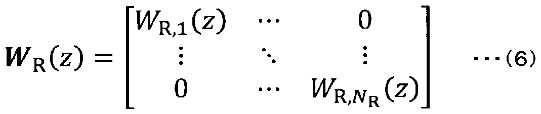
- the transfer function matrix ⁇ / ⁇ ( ⁇ ) on the receiving side calculated based on The transfer function matrix ⁇ / ⁇ ( ⁇ ) is It is a matrix whose elements are transfer functions.
- the transfer function matrix ⁇ / ⁇ ( ⁇ ) is 0 0 estimated by the receiving station device 102 from the training signal transmitted from the transmitting station device 101. It is calculated based on and equalizes 3 I.
- the receiving side linear equalization unit 302 since the inverse matrix 1 to
- the 0 1 ⁇ /1 demodulation unit 303 demodulates the equalized ⁇ 3 stream data signals 3 ⁇ ( n ) of I 3 I output from the reception side linear equalization unit 302 into information bits. , Output the bit string.
- the receiving side linear equalization unit 302 is Since (
- the receiving station device 102 It is possible to demodulate the data signal by equalizing 3 I from the signal received by each of the 8 antennas.
- the receiving station device 102 receives 0 I from the training signal transmitted from the transmitting station device 101. Then, the receiving station apparatus 102 calculates a transfer function matrix for I 3 I equalization. Further, the transfer function matrix used by the transmission side linear equalization unit 202 may be calculated by the receiving station device 102 side and transmitted to the transmitting station device 101 side as described later, or the receiving station device 1 It is also possible to transmit 0 I information from the 02 side to the transmitting station device 101 side and calculate the transfer function matrix at the transmitting station device 101 side. ⁇ 2020/175 280 9 boxes (:171? 2020/006548
- 3 ( n ) is the data signal output from the 08 IV! modulator 201, and the transfer function matrix of the transmitter-side linear equalizer 202 is ,
- the transfer function matrix of the receiving side linear equalization unit 302 is ⁇ / ⁇ ( ⁇ ), and the data signal output from the 0 ! ⁇ /1 demodulation unit 303 is 3 ( n ),
- the additive noise is 7? ( n )
- the relationship between signals transmitted and received in the wireless communication system 100 according to the present embodiment can be expressed by equation (1).
- ⁇ represents the set of elements of the matrix, for example ⁇ ⁇ + 1 has a ( ⁇ + 1) elements.
- equation (1) the transfer function matrix 0 I of ! (2) is represented by equation (2).
- the transfer function of the transmitting side linear equalization unit 202 is The matrix obtained by multiplying the matrix ⁇ / ⁇ ( ⁇ ) and the transfer function row ⁇ / ⁇ ( ⁇ ) of the receiving side linear equalizer 302 is ⁇ .
- - 1 can be represented by the product of the transfer function of 1/ ⁇ 161: (1 ⁇ 1 (a)) and the matrix of 301" (1 ⁇ 1 (a) ).
- d e t () and a d j () are the determinant and ad jug ate matrix, respectively.
- a dj is different from the adjoint matrix (ad j ⁇ i nt matrix) that represents the Hermitian transpose.
- Equation (8) the adjoint matrix of the transfer function matrix H(z) of the channel response is taken as the transfer function matrix, and the transfer function matrix W T (z) of the transmission side linear equalization unit 202 is given by Equation (9).
- the transmission-side linear equalization unit 202 and the reception-side linear equalization unit 302 share the 0 I Of the transfer function matrix ! ⁇ I ( ⁇ ) can be multiplied by 1 ⁇
- Equation (12) corresponds to Equation (8) and represents the transfer function matrix () for equalization of the entire wireless communication system 100.
- the applicability of the type I equalizer is determined as follows.
- FIG. 2 shows an example of an impulse response of 1/61: (1 to 1 (2) ).
- the horizontal axis represents the time corresponding to the delay taps of the I-equalizer ( ⁇ - ⁇ , ⁇ ⁇ ⁇ ... ), and the vertical axis represents the amplitude of the signal held in each delay tap.
- Figure 2 (3) shows The amplitude of each delay tap when (1 to 1 (2)) is the minimum phase is shown in Fig. 2 ( ⁇ ). It shows the amplitude of each delay tap when (1 to 1 (2)) is non-minimum phase.
- FIG. 2(a), )) is the minimum phase, the amplitude of the signal of the delay tap becomes smaller, and the impulse response of ⁇ 161: (1 ⁇ 1 ( ⁇ )) converges and approaches 0, so it can be approximated by type I. Yes, the operation of the equalizer is stable.
- ⁇ 16 I (1 to 1 (2)) has a non-minimum phase, the signal amplitude of the delay tap increases, and ⁇ 16 (1 to 1 (
- Fig. 3 shows an example of the positions of the poles of 1/61: (1 to 1 (2) ).
- the poles (1 to 1 (2)) are stable when inside the unit circle except the circumference on the plane with the real axis 6 and the imaginary axis I 01, but outside the unit circle except the circumference on the complex plane. Becomes unstable and the impulse response diverges.
- the poles correspond to the roots of the denominator polynomial in Eq. (1 3).
- ! ⁇ 1 is the number of antennas! _ Is the number of delay paths.
- the direction of the equalizer is switched to the reverse direction when it is determined to be in the non-minimum phase by any of the methods described above.
- FIG. 4 shows an example of the directions of the equalizers.
- Fig. 4 (a) and Fig. 4 (10) show the impulse response at the minimum phase described in Fig. 2 (Fig. 2 (3)) and the impulse response at the non-minimum phase (Fig. 2 (10)).
- Figure 4 ( ⁇ ) and Figure 4 ( ⁇ 0 show the received data signal ( ⁇ ) for ! ⁇ 1 samples (! ⁇ ! is an integer) along the horizontal axis in the time direction.
- the minimum shown in Figure 4 ( ⁇ ) At the time of phase, the reception side linear equalization unit 3002 performs forward equalization in the time axis direction.In the forward direction equalization, the reception side linear equalization unit 3002 uses the equation (7) described above. ) Operates as an equalizer. ⁇ 02020/175 280 16 ⁇ (: 17 2020 /006548
- FIG. 5 shows the transmitting station device 101 and the receiving station device 102 according to the first embodiment. An example is shown. Note that FIG. 5 shows a detailed configuration example of the transmitting station device 101 and the receiving station device 102 described in FIGS. 1 and 2.
- transmitting station apparatus 101 includes information bit generating section 401, data signal modulating section 402, training signal generating section 403, transmitting side linear equalizing section 404, transmitting signal converting section 405, received signal.
- the conversion unit 406 and the antennas AT t (1) to the antenna AT t (N T ) have N T antennas. Also, have you 5, the receiving station apparatus 1 ⁇ 2, N R antennas, the reception signal conversion unit 501, channel estimation section 502 of the antenna AT r (1) from the antenna AT r (N R), linear It has an equalizer coefficient calculation unit 503, a reception side linear equalization unit 504, a data signal demodulation unit 505, an information bit detection unit 506, and a transmission signal conversion unit 507.
- the information bit generator 401 generates a data information bit to be transmitted to the receiving station device 102.
- the data information bit is a bit string corresponding to, for example, a data signal input from the outside (not shown) or a data signal generated internally.
- the information bit generation unit 401 may have an error correction coding function for generating an error correction code at a predetermined coding rate, an interleave function, or the like.
- Data signal modulating section 402 outputs a data signal S(n) obtained by modulating the bit string output from information bit generating section 401 by a predetermined modulation method (for example, quadrature amplitude modulation (QAM)).
- a predetermined modulation method for example, quadrature amplitude modulation (QAM)
- the bit string output by the information bit generation unit 401 is divided into a plurality of streams according to the number of antennas AT t, and the modulated data signal S(n) is output for each stream. Therefore, the data signal modulator 402 is provided for each stream.
- the training signal generation unit 403 generates a training signal for estimating the channel response (CIR) (corresponding to the training signal generation process).
- predetermined information such as a preamble for signal detection (eg, a specific pattern such as an alternating pattern of “01”) is modulated by a modulation method that is less susceptible to interference such as PSK (Phase Shift Keying). Is a predetermined signal that is used by the receiving station device 102 to estimate C R.
- PSK Phase Shift Keying
- the information on the training signal to be transmitted is known in advance with the receiving station device 102.
- the transmission-side linear equalization unit 404 corresponds to the transmission-side linear equalization unit 202 described in Fig. 1 and outputs the data signal 3 ( n ) ( Outputs a signal (corresponding to the second data signal) obtained by equalizing I from (corresponding to the first data signal) to the transmission signal conversion unit 405 (corresponding to the linear equalization processing on the transmission side).
- the transmission-side linear equalization unit 404 holds, for example, the data signal output from the data signal modulation unit 502, has a delay tap that shifts at fixed intervals, and the signal of each delay tap has a predetermined tap. It can be realized with an I-type equalizer that outputs the sum of signals multiplied by coefficients.
- the tap coefficient is 0 I estimated by the receiving station device 102. These are the coefficients that form the transfer function for Eighth I equalization calculated based on Eq. (9), and realize the Eq.
- the transmission side linear equalization unit 404 performs linear equalization processing for equalizing II. At the same time as linear equalization processing, processing to normalize transmission power is also performed.
- the transmission side linear equalization unit 404 outputs the training signal output from the training signal generation unit 403 as it is without performing linear equalization processing.
- the transmission signal conversion unit 405 frequency-converts the data signal or training signal output by the transmission-side linear equalization unit 404 into a high-frequency transmission signal to be transmitted from the antenna 8-chome 1. For example, the transmission signal conversion unit 405 up-converts the data signal or training signal in the 2 0 1 ⁇ 1! band to a high frequency signal in the 5° 1 to 12 band and sends it out from the antenna 8-chome 1:. ..
- each of the streams divided into multiple streams is converted into a high-frequency signal and sent from each of antenna 8 (1) to antenna 8 (1 ⁇ 17 ).
- the reception signal conversion unit 406 frequency-converts the high-frequency reception signals received by the antennas from antenna 8 (1) to antenna 8 (1 ⁇ 17 ) into low-frequency baseband signals. For example, the reception signal conversion unit 406 down-converts the high-frequency signal in the 5O! ⁇ 12 band to output the baseband signal in the 2O1 ⁇ ( ⁇ !2 band. Then, the received signal converter 406 is ⁇ 2020/175 280 19 ⁇ (:171? 2020/006548
- the device 102 receives a control signal containing information such as tap coefficients that make up the transfer function used in the transmission side linear equalization section 202 from the device 102, converts it to a baseband signal, and transmits it to the transmission side linear equalization section 40. Output to 4.
- the function of the demodulation unit that demodulates information such as tap coefficient from the baseband signal may be included in the transmission side linear equalization unit 202, or the reception signal conversion unit 40 6 may perform tap coefficient and other functions.
- the information may be demodulated and output to the transmission side linear equalization unit 404.
- the transmission signal conversion unit 405 and the reception signal conversion unit 406 correspond to the transmission station communication unit that performs transmission station communication processing.
- Antenna Hatcho has antennas for transmitting and receiving from Antenna Hatcho (1) to Antenna Hatcho (1 ⁇ 1 lower), and the high frequency signal output from the transmission signal conversion unit 450 is used as electromagnetic waves in the space. Radiate to. Alternatively, the antenna Hatcho converts the electromagnetic waves in the space transmitted from the receiving station device 102 into a high frequency signal, and outputs the high frequency signal to the received signal conversion unit 406.
- the transmitting station apparatus 101 can transmit to the receiving station apparatus 102 a data signal obtained by equalizing the 8 I by the transmitting side linear equalization unit 20 2.
- Antenna Hatcho has R transmitting and receiving antennas from Antenna Hatcho “(1) to Antenna Hatcho “(1 ⁇ 10), and outputs the high-frequency signals output by the transmission signal conversion unit 507, which will be described later. It radiates into space as electromagnetic waves.
- Antenna Hatcho "converts the electromagnetic waves in the space transmitted from the transmitting station device 101 into high frequency signals and outputs them to the receiving signal converter 5 0 1 described later. ..
- the received signal conversion unit 501 receives signals from each of the antenna 8-chome "(1) to the antenna 8-chome "(1 ⁇ )" in the same way as the received signal conversion unit 406 of the transmitting station device 1 0 1.
- the high-frequency signal that is generated is frequency-converted to a baseband signal, where the training signal received from the transmitting station device 101 is output to the communication channel estimator 502 and received from the transmitting station device 101.
- the data signal is output to the linear equalizer 504 on the receiving side.
- the communication channel estimation unit 502 is a training signal transmitted from the transmission station device 1 0 1. Estimate (corresponding to the communication channel estimation process). ⁇ 2020/175 280 20 units (: 171-1? 2020/006548
- the linear equalizer coefficient calculation unit 50 3 is a channel estimation unit.
- the tap coefficients that make up the transfer function for II equalization (corresponding to the transfer function at the transmission side) used by the transmission side linear equalization unit 40 4 of the transmission station device 101 and the reception station device 1 0 2 A tap coefficient that constitutes a transfer function for I 3 I equalization (corresponding to the transfer function on the reception side) used by the reception side linear equalization unit 504 of is calculated.
- the method of calculating each tap coefficient uses the method described in Fig. 1. Then, information such as the tap coefficient that constitutes the transfer function for I-square equalization calculated by the linear equalizer coefficient calculation unit 50 3 is transmitted to the transmitting station apparatus 1 0 1 side.
- the transmission side transfer function is The adjoint matrix of (A) is the transfer function
- the transfer function of the receiving side is the transfer function matrix of ⁇ I!
- the inverse of the determinant of I(A) is the transfer function.
- the linear equalizer coefficient calculation unit 5033 corresponds to the reception-side coefficient calculation unit that performs reception-side coefficient calculation processing.
- the reception side linear equalization unit 50 4 corresponds to the reception side linear equalization unit 30 2 described in FIG. 1, and I 3 I etc. calculated by the linear equalizer coefficient calculation unit 50 3
- the data signal ( n ) (corresponding to the third data signal) obtained by equalizing 3 I from the signal output from the received signal conversion unit 5 0 1 to the data signal demodulation unit 5 0 5 using the transfer function for conversion.
- Output (corresponds to linear equalization processing on the receiving side).
- the receiving side linear equalization unit 504 as described in FIG. determinant of ( ⁇ ) (1 to 1 ()) is the minimum phase or the non-minimum phase, and if it is the minimum phase, forward equalization is performed, and if it is the non-minimum phase, the backward direction is equalized. Control so that
- the data signal demodulation unit 505 demodulates the equalized data signal 3 ( n ) of I3 output from the reception side linear equalization unit 504 into information bits, and outputs a bit string. Output. Since the receiving-side linear equalization unit 505 outputs multiple stream data signals 3 ⁇ ( n ) according to the number of antennas, the data signal demodulation unit 505 1! for each stream, and the data signal demodulation unit 505 provides the information of the bit sequence obtained by combining the bit sequences divided into a plurality of streams on the transmitting station device 101 side. It is output to the bit detector 506. ⁇ 2020/175 280 21 ⁇ (: 171? 2020 /006548
- the evening signal demodulation unit 505 may have an error correction decoding function and a deinterleaving function depending on the function of the transmitting station device 101 side.
- the information bit detection unit 506 outputs received data obtained by converting the bit string output by the data signal demodulation unit 505 into digital data.
- the error correction decoding function and the deinterleaving function may be performed on the information bit detection unit 506 side.
- the transmission signal conversion unit 507 converts the information output by the linear equalizer coefficient calculation unit 503 into a high frequency signal and outputs it from the antenna D1.
- Information such as tap coefficients that make up (a) is transmitted from the antenna unit to the transmitting station device 101 side.
- the function of the modulation unit that modulates information such as tap coefficients into a baseband signal is the transmission signal.
- the conversion unit 5 07 may have the linear equalizer coefficient calculation unit 5 03.
- the reception signal conversion unit 5 0 1 and the transmission signal conversion unit 5 0 7 Corresponds to the receiving station communication unit that performs receiving station communication processing.
- the receiving station device 10 And ⁇ 3 I Calculate the tap coefficients that make up the transfer function for equalization. Then, the tap coefficient for the 3 I equalization is set in the receiving side linear equalization unit 504, and the tap coefficient for the I equalization is transmitted to the transmitting station device 1 0 1, and the linear equalization at the transmitting side is performed. Set to part 4 04. As a result, the equalization process of 0.88 can be performed on the side of the transmitting station device 101, and the equalization process of 3x10 can be performed on the side of the receiving station device 102.
- the receiving side linear equalization unit 504 is Determinant of transfer function row 1 to 1 (z) of (1 to 1 ()) is the minimum phase or non-minimum phase, and if it is the minimum phase, forward equalization is performed, and if it is the non-minimum phase, the reverse direction is performed. Control to perform equalization.
- transfer function row 1 to 1 (z) of (1 to 1 ()) is the minimum phase or non-minimum phase, and if it is the minimum phase, forward equalization is performed, and if it is the non-minimum phase, the reverse direction is performed. Control to perform equalization.
- FIG. 6 shows an example of the transmitting station device 1013 and the receiving station device 1028 according to the second embodiment.
- the difference between the wireless communication system 1008 shown in Fig. 6 and the wireless communication system 100 described in Fig. 5 is that the transmitting station device 1 0 1 3 has a linear equalizer coefficient calculation unit 6 0 1 Is to have.
- slightly different from the receiving station apparatus 1 0 2 3 linear equalizer coefficient calculating unit 5 0 3 3 processing is the receiving station apparatus 1 0 2 linear equalizer coefficient calculating unit 5 0 3. Note that in FIG. 6, blocks having the same reference numerals as in FIG. 5 perform the same processing as in FIG.
- a linear equalizer coefficient calculating unit 5 0 3 3 based on 0 ⁇ the channel estimation unit 5 0 2 was estimated, as described in FIG. 1, receiver
- the receiving side linear equalization unit 50 4 of the station device 102 calculates the tap coefficient that constitutes the transfer function for I 3 I equalization.
- a linear equalizer coefficient calculating unit 5 0 3 3 constituting the transfer function for doing the equalization processing for equalizing II at transmitting station 1 0 1 of the transmission side linear equalizer unit 4 0 4
- the tap coefficient calculated by the channel estimation unit 50 2 The information regarding to the transmitting station device 1 0 1.
- ⁇ I The information regarding the information may be directly transmitted from the communication channel estimation unit 50 2 to the transmission station device 1 0 1 via the transmission signal conversion unit 5 07 from the antenna 8”.
- linear equalizer coefficient calculation section 6 0 1 receives information of 0 I transmitted from the receiving station 1 0 2 3, in FIG. 1
- the transmission side linear equalization unit 404 calculates the tap coefficient that constitutes the transfer function for II equalization, and sets it in the transmission side linear equalization unit 404.
- the linear equalizer coefficient calculation unit 60 1 corresponds to the transmission side coefficient calculation unit that performs the transmission side coefficient calculation process.
- the radio communication system 1003 according to the present embodiment is the same as the radio communication system 100 according to the first embodiment, and the training transmitted by the transmitting station device 1013 is performed. From signal I , But I The information related to is transmitted to the transmitting station device 1 103 side, and the tap coefficient constituting the transfer function for II equalization is calculated on the transmitting station device 10 13 side. This makes the transfer function for equalization ⁇ 2020/175 280 23 ⁇ (:171? 2020 /006548
- the processing amount of linear equalizer coefficient calculation unit 503 3 the first embodiment forms state It can be smaller than the processing amount of the linear equalizer coefficient calculation unit 503.
- the receiving side linear equalization unit 504 as described in FIG. ⁇ ⁇ transfer function matrix! ⁇ determinant of I ( ⁇ ) (1 to 1 ()) is the minimum phase or non-minimum phase, and if it is the minimum phase, forward equalization is performed, and if it is the non-minimum phase, backward equalization is performed. Control to do. As a result, even in the case of non-minimum phase, it is possible to calculate as the apparent minimum phase by performing backward equalization, and stable equalization processing can be realized without diverging the impulse response. ..
- the wireless communication system As described above in each embodiment, the wireless communication system, the wireless communication method, the transmitting station apparatus, and the receiving station apparatus according to the present invention, I 1 ⁇ /1 ⁇
- the transfer function of the equalizer has the minimum phase or non-minimum phase and changing the equalization direction, a part of the transfer function of the equalizer is Even in the case of the minimum phase, it is possible to perform stable equalization of 8 8 and 3 3 in a stable manner.
Landscapes
- Engineering & Computer Science (AREA)
- Computer Networks & Wireless Communication (AREA)
- Signal Processing (AREA)
- Cable Transmission Systems, Equalization Of Radio And Reduction Of Echo (AREA)
- Radio Transmission System (AREA)
Abstract
送信局装置は、トレーニング信号生成部と、送信側伝達関数によりデータ信号を等化する送信側線形等化部と、トレーニング信号または複数のデータ信号を送信し、送信側伝達関数の情報を受信局装置から受信する送信局通信部とを備え、受信局装置は、トレーニング信号から通信路応答を推定する通信路推定部と、通信路応答の伝達関数行列Hの随伴行列を伝達関数とする送信側伝達関数と、伝達関数行列Hの行列式の逆数を伝達関数とする受信側伝達関数とを算出する受信側係数算出部と、受信側伝達関数を用いて受信信号を等化する受信側線形等化部とを備え、受信側線形等化部は、伝達関数行列Hの行列式が最小位相であるか否かを判定し、最小位相である場合には順方向等化を行い、非最小位相である場合には逆方向等化を行う。
Description
明 細 書
発明の名称 :
無線通信システム、 無線通信方法、 送信局装置および受信局装置
技術分野
[0001 ] 本発明は、 S C— M I M 0 (Single Carrier Multiple-Input Mu It i p le-Ou tput) 伝送を行う無線通信システムにおいて、 アンテナ間干渉とシンボル間 干渉とを抑制する時間領域線形等化器の技術に関する。
背景技術
[0002] 周波数選択性のフエージングがある通信環境下で広帯域の SC_M I M〇 伝送を行う場合、 複数のアンテナの空間的な広がりにより生じる 丨 A I (Int er-Antenna Interference : アンテナ間干渉) と、 通信路特性の時間的な広が りにより生じる 丨 S 丨 (Inter-Symbol Interference :シンボル間干渉) を抑 制するための処理が必要となる。
[0003] そこで、 時間領域線形等化器を用いて時間/空間方向に送信ビーム形成を 行うことで、 低処理遅延で I A I / I S I を同時に等化する方法が検討され ている (例えば、 非特許文献 1参照) 。
先行技術文献
非特許文献
[0004] 非特許文献 1 :栗山圭太,福園隼人,吉岡正文,立田努, “広帯域シングルキヤリ ア M I MO伝送のための F I R型送信ビーム形成” 信学技報, voU 18, no.435 , RCS2018-247, pp.31-36, 2019年 1月.
発明の概要
発明が解決しようとする課題
[0005] ところが、 非特許文献 1のように、 C I Rの伝達関数行列 H (z) の逆行 列 H-i (z) を線形等化器の伝達関数に用いる手法では、 等化器の伝達関数 を算出する過程で伝達関数の一部が非最小位相となる場合に適用できないと いう問題がある。 ここで、 伝達関数の零点配置が単位円内に分布する場合に
〇 2020/175280 2 卩(:171? 2020 /006548
最小位相となり、 伝達関数の零点配置が単位円外に分布する場合に非最小位 相となる。 非最小位相の場合、 等化器の動作が不安定になってインパルス応 答が発散する可能性があるため、 等化器の伝達関数の一部が非最小位相とな る場合に適用できないという問題が生じる。
[0006] 本発明は、

るか非最小位相となるかを判定して等化方向を変えることによって、 等化器 の伝達関数の一部が非最小位相となる場合でも安定して動作し、 丨 八 I およ び丨 3 I を等化できる無線通信システム、 無線通信方法、 送信局装置および 受信局装置を提供することを目的とする。
課題を解決するための手段
[0007] 第 1の発明は、 送信局装置と受信局装置との間で

う無線通信システムにおいて、 前記送信局装置は、 既知のトレ _ニング信号 を生成するトレーニング信号生成部と、 送信側伝達関数を用いて複数の第 1 データ信号を等化した複数の第 2データ信号を出力する送信側線形等化部と 、 前記トレーニング信号または複数の前記第 2データ信号を前記受信局装置 に送信し、 前記送信側伝達関数に関する情報を前記受信局装置から受信する 複数のアンテナを有する送信局通信部とを備え、 前記受信局装置は、 前記送 信局装置が送信する複数の前記第 2データ信号または前記トレーニング信号 を受信し、 前記送信側伝達関数に関する情報を前記送信局装置に送信する複 数のアンテナを有する受信局通信部と、 前記受信局通信部により受信する前 記トレーニング信号から通信路応答を推定する通信路推定部と、 前記通信路 応答の伝達関数行列 ! !の随伴行列を伝達関数とする前記送信側伝達関数と、 前記伝達関数行列 ! !の行列式の逆数を伝達関数とする受信側伝達関数とを算 出する受信側係数算出部と、 前記受信側伝達関数を用いて前記受信局通信部 が受信する複数の前記第 2データ信号を等化した複数の第 3データ信号を出 力する受信側線形等化部とを備え、 前記受信側線形等化部は、 前記伝達関数 行列 1~1の行列式が最小位相であるか否かを判定し、 最小位相である場合には 順方向等化を行い、 非最小位相である場合には逆方向等化を行うことを特徴
〇 2020/175280 3 卩(:171? 2020 /006548
とする。
[0008] 第 2の発明は、 第 1の発明において、 前記受信側係数算出部は、 前記伝達 関数行列 ! !の行列式の逆数を伝達関数とする前記受信側伝達関数のみを算出 して、 前記通信路応答に関する情報を前記送信局装置へ送信し、 前記送信局 装置は、 前記受信局装置から受信する前記通信路応答に関する情報に基づい て、 前記通信路応答の伝達関数行列 ! !の随伴行列を伝達関数とする前記送信 側伝達関数を算出する送信側係数算出部をさらに備えることを特徴とする。
[0009] 第 3の発明は、 送信局装置と受信局装置との間で

う無線通信方法であって、 前記送信局装置は、 既知のトレーニング信号を生 成するトレーニング信号生成処理と、 送信側伝達関数を用いて複数の第 1デ —夕信号を等化した複数の第 2データ信号を出力する送信側線形等化処理と 、 前記トレーニング信号または複数の前記第 2データ信号を前記受信局装置 に送信し、 前記送信側伝達関数に関する情報を前記受信局装置から受信する 複数の送信局通信処理とを実行し、 前記受信局装置は、 前記送信局装置が送 信する複数の前記第 2データ信号または前記トレーニング信号を受信し、 前 記送信側伝達関数に関する情報を前記送信局装置に送信する複数の受信局通 信処理と、 前記送信局装置から受信する前記トレーニング信号から通信路応 答を推定する通信路推定処理と、 前記通信路応答の伝達関数行列 ! !の随伴行 列を伝達関数とする前記送信側伝達関数と、 前記伝達関数行列 !~1の行列式の 逆数を伝達関数とする受信側伝達関数とを算出する受信側係数算出処理と、 前記受信側伝達関数を用いて前記受信局通信処理により受信する複数の前記 第 2データ信号を等化した複数の第 3データ信号を出力する受信側線形等化 処理とを実行し、 前記受信側線形等化処理では、 前記伝達関数行列 1~1の行列 式が最小位相であるか否かを判定し、 最小位相である場合には順方向等化を 行い、 非最小位相である場合には逆方向等化を行うことを特徴とする。
[0010] 第 4の発明は、 第 3の発明において、 前記受信側係数算出処理では、 前記 伝達関数行列 ! !の行列式の逆数を伝達関数とする前記受信側伝達関数のみを 算出して、 前記通信路応答に関する情報を前記送信局装置へ送信し、 前記送
〇 2020/175280 4 卩(:171? 2020 /006548
信局装置は、 前記受信局装置から受信する前記通信路応答に関する情報に基 づいて、 前記通信路応答の伝達関数行列 ! !の随伴行列を伝達関数とする前記 送信側伝達関数を算出する送信側係数算出処理をさらに実行することを特徴 とする。
[001 1 ] 第 5の発明は、 受信局装置との間で

において、 前記受信局装置が通信路応答を推定するための既知のトレーニン グ信号を生成するトレーニング信号生成部と、 前記通信路応答の伝達関数行 列 の随伴行列を伝達関数とする送信側伝達関数を用いて複数の第 1データ 信号を等化した複数の第 2データ信号を出力する送信側線形等化部と、 前記 トレーニング信号または複数の前記第 2データ信号を前記受信局装置に送信 し、 前記送信側伝達関数に関する情報を前記受信局装置から受信する複数の アンテナを有する送信局通信部とを備えることを特徴とする。
[0012] 第 6の発明は、 第 5の発明において、 前記送信局装置は、 前記受信局装置 から受信する前記通信路応答に関する情報に基づいて、 前記通信路応答の伝 達関数行列 ! !の随伴行列を伝達関数とする前記送信側伝達関数を算出する送 信側係数算出部をさらに備えることを特徴とする。
[0013] 第 7の発明は、 送信局装置との間で

において、 前記送信局装置が送信する複数の第 2データ信号またはトレーニ ング信号を受信し、 前記送信局装置の等化器で用いる送信側伝達関数に関す る情報を前記送信局装置に送信する複数のアンテナを有する受信局通信部と 、 前記受信局通信部により受信する前記トレーニング信号から通信路応答を 推定する通信路推定部と、 前記通信路応答の伝達関数行列 ! !の随伴行列を伝 達関数とする前記送信側伝達関数と、 前記伝達関数行列 ! !の行列式の逆数を 伝達関数とする受信側伝達関数とを算出する受信側係数算出部と、 前記受信 側伝達関数を用いて前記受信局通信部が受信する複数の前記第 2データ信号 を等化した複数の第 3データ信号を出力する受信側線形等化部とを備え、 前 記受信側線形等化部は、 前記伝達関数行列 ! !の行列式が最小位相であるか否 かを判定し、 最小位相である場合には順方向等化を行い、 非最小位相である
〇 2020/175280 5 卩(:171? 2020 /006548
場合には逆方向等化を行うことを特徴とする。
[0014] 第 8の発明は、 第 7の発明において、 前記受信側係数算出部は、 前記伝達 関数行列 !!の行列式の逆数を伝達関数とする前記受信側伝達関数のみを算出 して、 前記通信路応答に関する情報を前記送信局装置へ送信することを特徴 とする。
発明の効果
[0015] 本発明に係る無線通信システム、 無線通信方法、 送信局装置および受信局 装置は、

非最小位相となるかを判定して等化方向を変えることによって、 等化器の伝 達関数の一部が非最小位相となる場合でも安定して動作し、 丨 八 I および I 3 I を等化できる。
図面の簡単な説明
[0016] [図 1]第 1実施形態および第 2実施形態に係る無線通信システムの一例を示す 図である。
[図 2] 1 /〇161: (1~1 ( å) ) のインパルス応答の一例を示す図である。
[図 3] 1 /〇161: (1~1 { 2.) ) の極の位置の一例を示す図である。
[図 4]等化器の方向の一例を示す図である。
[図 5]第 1実施形態に係る送信局装置および受信局装置の一例を示す図である
[図 6]第 2実施形態に係る送信局装置および受信局装置の一例を示す図である
発明を実施するための形態
[0017] 以下、 図面を参照して本発明に係る無線通信システム、 無線通信方法、 送 信局装置および受信局装置の実施形態について説明する。
[0018] 図 1は、 第 1実施形態および第 2実施形態に係る無線通信システム 1 00 の一例を示す。 図 1 において、 無線通信システム 1 〇〇は、 複数 (1\1て個: 丁³2の整数) のアンテナ八丁 I (1 ) からアンテナ八丁 I (1\17) を有する 送信局装置 1 〇 1 と、 複数 (!\^個: !\^³2の整数) のアンテナ 丁 「 (1
) からアンテナ AT r (N R) を有する受信局装置 1 02とを備え、 送信局装 置 1 01 と受信局装置 1 02との間で無線通信を行う。 ここで、 以降の説明 において、 送信局装置 1 01のアンテナ AT t ( 1 ) からアンテナ AT t ( NT) に共通の説明を行う場合は符号末尾の (番号) を省略してアンテナ AT tと表記し、 特定のアンテナを指す場合は符号末尾に (番号) を付加して例 えばアンテナ AT t (1 ) のように表記する。 受信局装置 1 02のアンテナ AT r (1 ) からアンテナ AT r (NR) についても同様に表記する。 また、 複数の同じブロックを有する場合についても同様に表記する。
[0019] 本実施形態に係る無線通信システム 1 00は、 送信局装置 1 01 と受信局 装置 1 02の間で複数のアンテナを用いた広帯域の SC— M 丨 M〇方式によ る無線通信を行う。 ここで、 送信局装置 1 〇 1 と受信局装置 1 02の間の無 線通信路では、 マルチパスなど遅延時間が異なる複数の遅延波が存在し、 周 波数選択性のフエージングが生じる。 このため、 アンテナ間干渉 (丨 A I ) と通信路特性によるシンボル間干渉 (丨 S I ) とを抑制する必要がある。 図 1の例では、 送信局装置 1 01の NT個のアンテナと、 受信局装置 1 O 20N R個のアンテナとの間で空間的な広がりによるアンテナ間干渉 (丨 A I ) が生 じる。 また、 送信局装置 1 〇 1 と受信局装置 1 02のそれぞれのアンテナ間 で送受信される信号には、 時間的な広がりによるシンボル間干渉 (丨 S I ) が生じる。 ここで、 送信局装置 1 〇 1 と受信局装置 1 02との間の無線通信 路の通信路応答 (C I R) を H (z) とすると、 通信路応答 H (z) は、 複 数のアンテナの数に応じて NTX N Rを要素とする伝達関数の行列 (伝達関数 行列と称する) で表すことができる。
[0020] 図 1 において、 送信局装置 1 〇 1は、 Q AM変調部 201、 送信側線形等 化部 202、 R F部 203およびアンテナ AT tを備える。
[0021] Q AM変調部 201は、 受信局装置 1 〇 2へ送信するデータ情報ビッ トの ビッ ト列を直交振幅変調 (QAM : Quadrature Amplitude Modulation) した データ信号 S (n) (送信データ信号と称する) を出力する。 なお、 QAM 変調部 201は、 QAM変調部 201 ( 1 ) から Q A M変調部 201 (K)
を有し ( K : K ³ 1の整数) 、 K個のストリームに対応するデータ信号 S ( n) を出力する。 ここで、 データ信号 S (n) は、 KX 1 を要素とする行列 である。
[0022] 送信側線形等化部 202は、 送信局装置 1 01 と受信局装置 1 02との間 の C I Rに基づいて算出された送信側の伝達関数行列 WT (z) により等化処 理を行う。 伝達関数行列 WT (z) は、 NTXK個の伝達関数を要素とする行 列である。 なお、 等化処理と同時に送信電力を正規化する処理も行われる。 ここで、 本実施形態では、 送信側線形等化部 202は、 送信ビーム形成によ り 丨 A Iの等化を行う。 送信側線形等化部 202は、 例えば Q AM変調部 2 01が出力するデータ信号を保持し、 一定時間毎にシフトする遅延タップを 有し、 各遅延タップの信号に所定のタップ係数を乗算した信号の和を出力す る F 丨 R (Finite Impulse Response) 型の等化器で実現できる。 ここで、 丨 A I等化用の伝達関数行列は、 送信局装置 1 01から送信されるトレーニン グ信号により受信局装置 1 02が推定した C 丨 Rに基づいて算出される。
[0023] R F部 203は、 N T個のアンテナ A T tにそれぞれ対応する N T個の R F 部 203 (1 ) から R F部 203 (NT) を有し、 送信側線形等化部 202が 出力する 丨 A 丨の等化されたデータ信号またはトレーニング信号を高周波の 送信信号に周波数変換して、 ストリーム毎にアンテナ A T tから送出する。
[0024] アンテナ AT tは、 アンテナ AT t (1 ) からアンテナ AT t (NT) の N T個の送受信用のアンテナを有し、 R F部 203が出力する高周波信号を電磁 波として空間に放射する。
[0025] このようにして、 送信局装置 1 01は、 丨 A I を等化した送信信号を受信 局装置 1 02へ送信することができる。
[0026] 図 1 において、 受信局装置 1 02は、 アンテナ AT r、 R F部 301、 受 信側線形等化部 302および Q A M復調部 303を備える。
[0027] アンテナ AT rは、 アンテナ AT r ( 1 ) からアンテナ AT r (NR) の N R個の送受信用のアンテナを有し、 送信局装置 1 〇 1から送信された空間上の 電磁波を高周波信号に変換する。
〇 2020/175280 8 卩(:171? 2020 /006548
[0028]
 個のアンテナ八丁 「にそれぞれ対応する

部 301 ( 1 ) から 部 301 (1\1〇 を有し、 アンテナ八丁 「 ( 1 ) から アンテナ八丁 「 (1\1〇 が出力するそれぞれの高周波信号をベースバンド信号 に周波数変換する。
[0029] 受信側線形等化部 302は、 送信局装置 1 01 と受信局装置 1 02との間 の〇 I
 に基づいて算出された受信側の伝達関数行列 \/\^ (å) で等化処理を 行う。 伝達関数行列 \/\^ (å) は、
 個の伝達関数を要素とする行列で ある。 ここで、 伝達関数行列 \/\^ (å) は、 送信局装置 1 01から送信される トレーニング信号により受信局装置 1 02が推定した 0 丨
 に基づいて算出 され、 丨 3 I を等化する。 特に、 本実施形態では、 0 I の伝達関数行列 1~1 (å) の逆行列 1~|-1 (å) を線形等化器の伝達関数に用いるので、 受信側線 形等化部 302は、 後述するように、 伝達関数行列 \/\^ (å) の各伝達関数が 最小位相であるか非最小位相であるかを判定して、 最小位相である場合は等 化器の等化方向を順方向とし、 非最小位相である場合は等化器の等化方向を 逆方向とする制御を行う。
[0030] 0 1\/1復調部 303は、 受信側線形等化部 302が出力する I 3 Iの等化 された <個のストリームのデータ信号 3 ^ (n) を情報ビッ トに復調し、 ビ ッ ト列を出力する。 なお、 受信側線形等化部 302は、 アンテナ八丁 「の数
 (|-|) を出力するので、 0八1\/1 復調部 303は、 ストリーム毎にデータ信号 3 (n) を復調する。
[0031] このようにして、 受信局装置 1 02は、
 個のアンテナ八丁 「で受信する 信号から 丨 3 I を等化し、 データ信号を復調することができる。
[0032] なお、 受信局装置 1 02では、 送信局装置 1 01から送信されるトレーニ ング信号から 0 I
 を推定し、 受信局装置 1 02で I 3 I等化用の伝達関数 行列を算出する。 また、 送信側線形等化部 202が用いる伝達関数行列は、 後述するように、 受信局装置 1 〇 2側で算出して送信局装置 1 01側に送信 してもよいし、 受信局装置 1 02側から送信局装置 1 01側に 0 I の情報 を送信して、 送信局装置 1 〇 1側で伝達関数行列を算出するようにしてもよ
〇 2020/175280 9 卩(:171? 2020 /006548
を推定し、 受信局装置 1 02で I 3 I等化用の伝達関数 行列を算出する。 また、 送信側線形等化部 202が用いる伝達関数行列は、 後述するように、 受信局装置 1 〇 2側で算出して送信局装置 1 01側に送信 してもよいし、 受信局装置 1 02側から送信局装置 1 01側に 0 I の情報 を送信して、 送信局装置 1 〇 1側で伝達関数行列を算出するようにしてもよ
〇 2020/175280 9 卩(:171? 2020 /006548
い。
[0033] 図 1 において、 〇八 IV!変調部 201が出力するデータ信号を 3 (n) 、 送 信側線形等化部 202の伝達関数行列を
 の伝達関数行列を !! (å) 、 受信側線形等化部 302の伝達関数行列を \/\^ (å) 、 0 !\/1復調 部 303が出力するデータ信号を 3 (n) 、 付加雑音を 7? (n) とすると 、 本実施形態に係る無線通信システム 1 〇〇において送受信される信号の関 係は、 式 (1 ) で表すことができる。
[0034] [数 1] ⑻ = 14^〇){//〇) 11^ 0)5(71) + ? /⑻ } ⑴
= %⑺/ /〇) 丁〇)5〇〇十%⑺ ⑻ ここで、 3 (n) 、 丁 ( ) 、 1~1 ) 、 \/\^ ) 、
 ) および V (门) は、 以下の通りである。
[0035] [数 2]

[0036] 式 (1 ) において、 0 I の伝達関数行列 !! (2) は、 式 (2) で表され る。
[0037] [数 3]

ここで、 伝達関数行列!· I (å) の各要素の伝達関数
 (å) は、 式 ( 3) で表される。 なお、
 の整数、 n tは1 £ n t£Ntの整 数である。 また、 式 (3) の記号 1~1および の下付き文字 n「および n ^は、 文書中で記載する場合、
 (å) のように n 「および n tと表記する。 他の記号の下付き文字についても同様に表記する。
[0038] [数 4]
 ここで、 - I :伝達関数の遅延作用素、 II ( :第门「番目の受信アン テナと第
 である。 丨 は、 0£ 1 £1__ 1 (!_は正の整数) の整数で、 パス数!-の中のパス番号を示す。 なお 、 パス数!-は、 マルチパスなどの数を示す。
[0039] また、 送信局装置 1 01の送信側線形等化部 202の伝達関数行列
 (2 ) は、 式 (4) で表される。
[0040] [数 5]
 ここで、 伝達関数行列 丁 (2) の各要素の伝達関数 丁,
 (2) は、 式 (5) で表される。 なお、 ( , 门 は、 第 1<番目 (1<は、

数) のストリームのデータ信号を入力し、 第 1番目の送信アンテナへ信号を 出力する送信側線形等化部 202の 番目のタップ係数を示す。 は、 0£ £ _ 1の整数で ( は正の整数) 、 送信側線形等化部 202のタップ数 の中のタツプ番号を示す。
[0041]
\¥02020/175280 11 卩(:17 2020 /006548
[数 6]
 また、 受信局装置 1 〇 2の受信側線形等化部 302の伝達関数行列 \/\^ (å ) は、 式 (6) で表される。
[0042] [数 7]


[0043] [数 8]

(送信側線形等化部 202および受信側線形等化部 302の伝達関数の算 出)
次に、 76 r〇- f 〇 r〇 I n 9規範での送信側線形等化部 202および 受信側線形等化部 302の伝達関数行列の算出について説明する。
[0044] 本実施形態では、 0 I
 (1~1 (å) ) の等化を送信局装置 1 01 と受信局 装置 1 02とで分割して行うので、 式 (8) に示すように、 送信側線形等化 部 202の伝達関数行列 \/\^ (å) と、 受信側線形等化部 302の伝達関数行 列 \/\^ (å) とを乗算した行列が〇
 (å) の逆行列 1~|-1
(å) となる。 ここで、 1~|-1 ) は、 1 /〇161: (1~1 (å) ) の伝達関数 と 301 」 (1~1 (å) ) の行列との積で表すことができる。
(å) の逆行列 1~|-1
(å) となる。 ここで、 1~|-1 ) は、 1 /〇161: (1~1 (å) ) の伝達関数 と 301 」 (1~1 (å) ) の行列との積で表すことができる。
[0045] [数 9]
WR(z)WT{z) == H-\z)
(8)
adj (//〇))
det(//(z)) ここで、 d e t ( ) 、 a d j ( ) はそれぞれ行列式、 随伴行列 (ad jug ate matrix) を表す。 なお、 a d jは、 エルミート転置を表す随伴行列 (adj 〇 i nt matrix) とは異なる。
[0046] 式 (8) において、 通信路応答の伝達関数行列 H (z) の随伴行列を伝達 関数行列とし、 送信側線形等化部 202の伝達関数行列 WT (z) を式 (9) とする。
[0047] [数 10]
WT(z)=ad)(H(z)) G <LNtXK 0) また、 式 (8) において、 通信路応答の伝達関数行列!· I (å) の行列式の 逆数を伝達関数行列とし、 受信側線形等化部 302の伝達関数行列 \/\^ (å) を式 (1 0) とする。
[0048] [数 11]
 ここで、 丨 は単位行列である。
[0049] 以上のような線形等化器の伝達関数行列
 ( 2 ) および伝達関数行列

(z) を乗算すれば、 信号の入出力関係は式 (1 1 ) のようになり、 データ 信号 3 (n) の復調が可能となる。
[0050] [数 12] (11)

このようにして、 本実施形態に係る無線通信システム 1 00は、 送信側線 形等化部 202と受信側線形等化部 302とが分担して、 0 I
 の伝達関数 行列!· I (å) の逆行列 1~|-1 (å) を乗算し、 時間領域線形等化器による 丨 八 I および丨 3 丨の等化を行うことができる。
[0051] ここで、
 (å) の逆行列 1~|-1 (å) を線形等化器 の伝達関数に用いる手法では、 伝達関数の算出過程で伝達関数の一部が非最 小位相となる場合に係数が発散してしまい、 等化器の適用ができないという 問題がある。
[0052] 式 (1 2) は、 式 (8) に対応し、 無線通信システム 1 〇〇全体の等化用 の伝達関数行列 ( ) を示す。
[0053] [数 13]
 式 ( 1 2) において、
 (1~1 (2) ) は、 式 ( 1 3) に示すよう に、 丨 丨 型等化器を構成するが、 式 (1 4) に示すように、 無限級数を用 いて 丨 型等化器で近似することができる。 ここで、 3 (〇 (丨 は 0£ I £ 1_- 1の整数) は、
 (1~1 (å) ) の係数に相当する。
[0054] [数 14] 13

[0055] [数 15]

って、 I 型等化器の適用可否を次のように判定する。
[0056] 61 (1~1 (å) ) が最小位相となる場合:適用可能
^ 61 (1~1 (2) ) が非最小位相となる場合:適用不可能 (等化器係数 が発散)
図 2は、 1 / 61: (1~1 (2) ) のインパルス応答の一例を示す。 図 2に おいて、 横軸は I 型等化器の遅延タップ (å-〇, å~\ · ) に 対応する時間、 縦軸は各遅延タップに保持された信号の振幅、 をそれぞれ示 す。 図 2 (3) は、
 (1~1 (2) ) が最小位相となる場合の各遅延タッ プの振幅を示し、 図 2 (匕) は、
 (1~1 (2) ) が非最小位相となる場 合の各遅延タップの振幅を示す。
[0057] 図 2 (a) において、
 ) ) が最小位相となる場合は、 遅延 タップの信号の振幅が小さくなっていき、 〇161: (1~1 (å) ) のインパルス 応答は収束し、 0に近づくので I 型で近似可能であり、 等化器の動作は 安定する。 一方、 図 2 (13) において、 ¢16 I (1~1 (2) ) が非最小位相と なる場合は、 遅延タップの信号の振幅が大きくなっていき、 〇16 (1~1 (å
) ) のインパルス応答は発散するので、 等化器の動作は不安定となり、 I 8型等化器の適用は難しい。
[0058] 図 3は、 1 / 61: (1~1 (2) ) の極の位置の一例を示す。 図 3において 、 式 (1 3) に示した
 (1~1 (2) ) の極は、 実軸 6と虚軸 I 01 とする 平面上で円周を除く単位円内にあるとき安定するが、 複素 平面上 で円周を除く単位円外にあるとき不安定となり、 インパルス応答は発散する 。 ここで、 極は、 式 (1 3) の分母の多項式の根に対応する。
[0059] (最小位相/非最小位相の判定方法)
最小位相と非最小位相とを判定する方法として、 以下の 2つの方法が考え られる。
[0060] <方法 1 >
方法 1では、 〇1㊀ 1: ( 1~1 (å) ) を式 ( 1 5 ) とした場合に、 丨 = { 1 ,
 } において、 式 (1 6) を満足するときに最小位相と
〇 2020/175280 15 卩(:171? 2020 /006548
} において、 式 (1 6) を満足するときに最小位相と
〇 2020/175280 15 卩(:171? 2020 /006548
する。 ここで、 !\1はアンテナ数、 !_は遅延パス数である。
[0061 ] [数 16] 叫- 1)
det(H(z)) = > 1 5
1=0
[0062] [数 17]
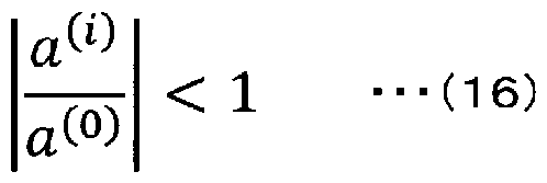 そして、 式 (1 6) を満たさず、 式 (1 7) のように、 左辺が 1以上とな る 3 が 1つ以上ある場合は、 非最小位相であると判定する。
[0063] [数 18]

<方法 2 >
方法 2では、 図 3で説明したように、 式 (1 5) について、 全ての零点が 複素 平面上の単位円の内側にあれば、 最小位相であると判定する。
[0064] [非最小位相時の処理]
本実施形態に係る無線通信システム 1 〇〇では、 上述のいずれかの方法に より、 非最小位相であると判定されたときに、 等化器の方向を逆方向に切り 替える。
[0065] 図 4は、 等化器の方向の一例を示す。 なお、 図 4 (a) および図 4 (1〇) は、 図 2で説明した最小位相時のインパルス応答 (図 2 (3) ) と非最小位 相時のインパルス応答 (図 2 (1〇) ) とに対応する。 図 4 (〇) および図 4 (¢0 は、 横軸の時間方向に !\1サンプル分 (!\!は整数) の受信データ信号丫 (〇) を示す。 図 4 (〇) に示す最小位相時には、 受信側線形等化部 3 0 2 は、 時間軸方向に順方向の等化を行う。 順方向等化では、 受信側線形等化部 3 0 2は、 先に説明した式 (7) に示す等化器として動作する。 一方、 逆方
\¥02020/175280 16 卩(:17 2020 /006548
向等化では、 式 (1 8) に示す等化器として動作する。
[0066] [数 19]
 式 (1 8) において、 遅延タップ は、 式 (7) の順方向等化と同じな ので、 各遅延タップの出力信号は順方向等化と同じであるが、 伝達関数 „ 「のタップ係数の方向が式 (7) とは逆になっている。 式 (7) の順方向等化 では、
 「であるのに対して、 式 ( 1 8) の逆方向等化では、 遅延タップ のタップ係数が -1 - „「とな る。 例えばタップ数〇= 3の場合、 遅延タップ は 9 = 0の -〇から 9 = 〇一 1 = 2の -2までの 3個なので、 順方向等化の = 0番目の遅延タップ 2-〇のタップ係数は、 w(o) R 9 = 1番目の遅延タップ のタップ係 数は、 ⑴ 9 = 2番目の遅延タップ _2のタップ係数は、 ⑵ „ 「となる。 これに対して、 逆方向等化の場合、 =〇番目の遅延タップ _〇の タップ係数は、 -卜⑴ 「= ¾/⑵ 〇「、 9 = 1番目の遅延タップ のタップ係数は、 (3-1-1) „「= ⑴ „「、 9 = 2番目の遅延タップ _2のタップ係数は、
 となる。 このように、 逆方 向等化の遅延タップ のタップ係数の順番は、 順方向等化のタップ係数の 順番と逆方向になる。
[0067] このようにして、 本実施形態に係る無線通信システム 1 00では、 0 I
 の伝達関数行列!· I (å) の行列式 61 (1~1 (å) ) が最小位相であるか非 最小位相であるかを判定し、 最小位相である場合には順方向等化を行い、 非 最小位相である場合には逆方向等化を行うように制御する。 これにより、 非 最小位相の場合でも、 逆方向等化を行うことで、 見かけ上は最小位相として 計算することができ、 インパルス応答が発散することがなくなる。
[0068] [第 1実施形態]
図 5は、 第 1実施形態に係る送信局装置 1 01および受信局装置 1 02の
一例を示す。 なお、 図 5は、 図 1および図 2で説明した送信局装置 1 01お よび受信局装置 1 〇 2の詳細な構成例を示す。
[0069] 図 5において、 送信局装置 1 01は、 情報ビッ ト生成部 401、 データ信 号変調部 402、 トレーニング信号生成部 403、 送信側線形等化部 404 、 送信信号変換部 405、 受信信号変換部 406およびアンテナ AT t (1 ) からアンテナ AT t (NT) の NT個のアンテナを有する。 また、 図 5にお いて、 受信局装置 1 〇 2は、 アンテナ AT r (1 ) からアンテナ AT r (NR ) の NR個のアンテナ、 受信信号変換部 501、 通信路推定部 502、 線形等 化器係数算出部 503、 受信側線形等化部 504、 データ信号復調部 505 、 情報ビッ ト検出部 506および送信信号変換部 507を有する。
[0070] 先ず、 送信局装置 1 01の構成について説明する。
[0071] 情報ビッ ト生成部 401は、 受信局装置 1 02へ送信するデータ情報ビッ 卜を生成する。 データ情報ビッ トは、 例えば外部 (不図示) から入力するデ —夕信号、 内部で生成するデータ信号などに対応するビッ ト列である。 なお 、 情報ビッ ト生成部 401は、 所定の符号化率で誤り訂正符号を生成する誤 り訂正符号化機能やインターリーブ機能などを有してもよい。
[0072] データ信号変調部 402は、 情報ビッ ト生成部 401が出力するビッ ト列 を所定の変調方式 (例えば直交振幅変調 (QAM) など) で変調したデータ 信号 S (n) を出力する。 なお、 本実施形態では、 情報ビッ ト生成部 401 が出力するビッ ト列をアンテナ AT tの数に応じて複数のストリームに分割 し、 各々のストリーム毎に変調したデータ信号 S ( n ) を出力するので、 各 ストリーム毎にデータ信号変調部 402を有する。
[0073] トレーニング信号生成部 403は、 通信路応答 (C I R) を推定するため のトレーニング信号を生成する (トレーニング信号生成処理に対応) 。 トレ —ニング信号は、 信号検出用のプリアンブルなどの予め決められた情報 (例 えば” 01” の交互パターン等の特定パターン) を PS K (Phase Shift Key ing) など干渉を受けにくい変調方式で変調した所定の信号であり、 受信局装 置 1 02で C 丨 Rを推定するために用いられる。 なお、 送信局装置 1 〇 1が
〇 2020/175280 18 卩(:171? 2020 /006548
送信するトレーニング信号の情報は、 予め受信局装置 1 0 2との間で既知で ある。
[0074] 送信側線形等化部 4 0 4は、 図 1で説明した送信側線形等化部 2 0 2に対 応し、 データ信号変調部 4 0 2が出力するデータ信号 3 (n) (第 1データ 信号に対応) から 丨 I を等化した信号 (第 2デ _夕信号に対応) を送信信 号変換部 4 0 5へ出力する (送信側線形等化処理に対応) 。 送信側線形等化 部 4 0 4は、 例えば、 データ信号変調部 4 0 2が出力するデータ信号を保持 し、 一定時間毎にシフトする遅延タップを有し、 各遅延タップの信号に所定 のタップ係数を乗算した信号の和を出力する I 型の等化器で実現できる 。 ここで、 タップ係数は、 受信局装置 1 0 2が推定した 0 I
 に基づいて算 出した丨 八 I等化用の伝達関数を構成する係数であり、 式 (9) で説明した 丁 (å) の等化器を実現する。 送信側線形等化部 4 0 4は、 I I を等化す るための線形等化処理を行う。 また、 線形等化処理と同時に送信電力を正規 化する処理も行われる。 なお、 送信側線形等化部 4 0 4は、 トレーニング信 号生成部 4 0 3が出力するトレーニング信号については、 線形等化処理を行 わずにそのまま出力する。
[0075] 送信信号変換部 4 0 5は、 送信側線形等化部 4 0 4が出力するデータ信号 またはトレーニング信号をアンテナ八丁 1から送出するための高周波の送信 信号に周波数変換する。 例えば、 送信信号変換部 4 0 5は、 2 0 1^ 1·! å帯域 のデータ信号またはトレーニング信号を 5◦ 1~1 2帯の高周波信号にアップコ ンバートして、 アンテナ八丁 1:から送出する。 ここで、 複数のストリームに 分割された各々のストリームは、 それぞれ高周波信号に変換され、 アンテナ 八丁 (1) からアンテナ八丁 (1\1 7) のそれぞれから送出される。
[0076] 受信信号変換部 4 0 6は、 アンテナ八丁 (1) からアンテナ八丁 (1\1 7 ) のそれぞれのアンテナにより受信された高周波の受信信号を低周波のベー スバンド信号に周波数変換する。 例えば、 受信信号変換部 4 0 6は、 5〇!~1 2帯の高周波信号をダウンコンバートして 2 0 1^(·! 2帯域のベースバンド信 号を出力する。 ここで、 本実施形態では、 受信信号変換部 4 0 6は、 受信局
〇 2020/175280 19 卩(:171? 2020 /006548
装置 1 0 2から送信側線形等化部 2 0 2で使用する伝達関数を構成するタッ プ係数などの情報を含む制御信号を受け取り、 ベースパンド信号に変換して 送信側線形等化部 4 0 4に出力する。 なお、 ベースパンド信号からタップ係 数などの情報を復調する復調部の機能は、 送信側線形等化部 2 0 2が有して もよいし、 受信信号変換部 4 0 6がタップ係数などの情報を復調して送信側 線形等化部 4 0 4へ出力してもよい。 ここで、 送信信号変換部 4 0 5および 受信信号変換部 4 0 6は、 送信局通信処理を行う送信局通信部に対応する。
[0077] アンテナ八丁 は、 アンテナ八丁 (1) からアンテナ八丁 (1\1下) の 丁個の送受信用のアンテナを有し、 送信信号変換部 4 0 5が出力する高周波信 号を電磁波として空間に放射する。 或いは、 アンテナ八丁 は、 受信局装置 1 0 2から送信された空間上の電磁波を高周波信号に変換して、 受信信号変 換部 4 0 6へ出力する。
[0078] このようにして、 送信局装置 1 0 1は、 送信側線形等化部 2 0 2により、 丨 八 I を等化したデータ信号を受信局装置 1 0 2へ送信することができる。
[0079] 次に、 図 5に示す受信局装置 1 0 2の構成について説明する。
[0080] アンテナ八丁 「は、 アンテナ八丁 「 ( 1) からアンテナ八丁 「 (1\1〇 の R個の送受信用のアンテナを有し、 後述する送信信号変換部 5 0 7が出力する 高周波信号を電磁波として空間に放射する。 或いは、 アンテナ八丁 「は、 送 信局装置 1 〇 1から送信された空間上の電磁波を高周波信号に変換して、 後 述する受信信号変換部 5 0 1へ出力する。
[0081 ] 受信信号変換部 5 0 1は、 送信局装置 1 0 1の受信信号変換部 4 0 6と同 様に、 アンテナ八丁 「 (1) からアンテナ八丁 「 (1\^) のそれぞれから受信 される高周波信号をベースパンド信号に周波数変換する。 ここで、 送信局装 置 1 0 1から受信するトレーニング信号は、 通信路推定部 5 0 2へ出力され 、 送信局装置 1 〇 1から受信するデータ信号は、 受信側線形等化部 5 0 4へ 出力される。
[0082] 通信路推定部 5 0 2は、 送信局装置 1 0 1から送信されるトレーニング信
 を推定する (通信路推定処理に対応) 。
〇 2020/175280 20 卩(:171? 2020 /006548
を推定する (通信路推定処理に対応) 。
〇 2020/175280 20 卩(:171? 2020 /006548
[0083] 線形等化器係数算出部 5 0 3は、 通信路推定部

基づいて、 送信局装置 1 〇 1の送信側線形等化部 4 0 4が用いる I I等化 用の伝達関数 (送信側伝達関数に対応) を構成するタップ係数と、 受信局装 置 1 0 2の受信側線形等化部 5 0 4が用いる I 3 I等化用の伝達関数 (受信 側伝達関数に対応) を構成するタップ係数とをそれぞれ算出する。 なお、 各 タップ係数の算出方法は、 図 1で説明した方法を用いる。 そして、 線形等化 器係数算出部 5 0 3が算出した I 丨等化用の伝達関数を構成するタップ係 数などの情報を送信局装置 1 0 1側に送信する。 ここで、 送信側伝達関数は 、
 ( å ) の随伴行列を伝達関数とし、 受信側伝達関 数は、 〇 I の伝達関数行列!· I ( å ) の行列式の逆数を伝達関数とする。 な お、 線形等化器係数算出部 5 0 3は、 受信側係数算出処理を行う受信側係数 算出部に対応する。
[0084] 受信側線形等化部 5 0 4は、 図 1で説明した受信側線形等化部 3 0 2に対 応し、 線形等化器係数算出部 5 0 3が算出した I 3 I等化用の伝達関数を用 いて、 受信信号変換部 5 0 1が出力する信号から 丨 3 I を等化したデータ信 ( n ) (第 3データ信号に対応) をデータ信号復調部 5 0 5へ出力す る (受信側線形等化処理に対応) 。 ここで、 受信側線形等化部 5 0 4は、 図 4で説明したように、
 ( å ) の行列式
 ( 1~1 ( å ) ) が最小位相であるか非最小位相であるかを判定し、 最小位相である場 合には順方向等化を行い、 非最小位相である場合には逆方向等化を行うよう に制御する。
[0085] データ信号復調部 5 0 5は、 受信側線形等化部 5 0 4が出力する I 3 丨の 等化されたデータ信号 3 ( n ) を情報ビッ トに復調し、 ビッ ト列を出力す る。 なお、 受信側線形等化部 5 0 4は、 アンテナ八丁 「の数に応じて複数の ストリームのデータ信号 3 ^ ( n ) を出力するので、 データ信号復調部 5 0 5は、 データ信号 3 ( 1·! ) をストリーム毎に復調する。 そして、 データ信 号復調部 5 0 5は、 送信局装置 1 0 1側で複数のストリームに分割されたビ ッ ト列を結合したビッ ト列を情報ビッ ト検出部 5 0 6に出力する。 なお、 デ
〇 2020/175280 21 卩(:171? 2020 /006548
—夕信号復調部 5 0 5は、 送信局装置 1 0 1側の機能に応じて、 誤り訂正復 号機能やデインターリーブ機能を備えてもよい。
[0086] 情報ビッ ト検出部 5 0 6は、 データ信号復調部 5 0 5が出力するビッ ト列 をデジタルデータに変換した受信データを出力する。 なお、 誤り訂正復号機 能やデインターリーブ機能を情報ビッ ト検出部 5 0 6側で行ってもよい。
[0087] 送信信号変換部 5 0 7は、 線形等化器係数算出部 5 0 3が出力する情報を 高周波信号に変換してアンテナ 丁 1から送出する。 例えば、 本実施形態で は、 線形等化器係数算出部 5 0 3が算出した I I を等化するための伝達関 数行列
 ( å ) を構成するタップ係数などの情報をアンテナ 丁 「から送信 局装置 1 〇 1側に送信する。 なお、 タップ係数などの情報をベースバンド信 号に変調する変調部の機能は、 送信信号変換部 5 0 7が有してもよいし、 線 形等化器係数算出部 5 0 3が有してもよい。 ここで、 受信信号変換部 5 0 1 および送信信号変換部 5 0 7は、 受信局通信処理を行う受信局通信部に対応 する。
[0088] このようにして、 受信局装置 1 0 2は、 送信局装置 1 0 1が送信するトレ
 および丨 3 I等化用の伝達関数を構成するタップ係数を算出する。 そして、 丨 3 I等化 用のタップ係数は受信側線形等化部 5 0 4に設定され、 丨 I等化用のタッ プ係数は送信局装置 1 〇 1 に送信されて送信側線形等化部 4 0 4に設定され る。 これにより、 丨 八 丨の等化処理を送信局装置 1 0 1側で行い、 丨 3 丨の 等化処理を受信局装置 1 0 2側で行うことができる。 特に、 本実施形態では 、 受信側線形等化部 5 0 4は、 図 4で説明したように、 0 I
 の伝達関数行 列 1~1 ( z ) の行列式
 ( 1~1 ( å ) ) が最小位相であるか非最小位相であ るかを判定し、 最小位相である場合には順方向等化を行い、 非最小位相であ る場合には逆方向等化を行うように制御する。 これにより、 非最小位相の場 合でも、 逆方向等化を行うことで、 見かけ上は最小位相として計算すること ができ、 インパルス応答が発散することなく、 安定した等化処理を実現する ことができる。
〇 2020/175280 22 卩(:171? 2020 /006548
( 1~1 ( å ) ) が最小位相であるか非最小位相であ るかを判定し、 最小位相である場合には順方向等化を行い、 非最小位相であ る場合には逆方向等化を行うように制御する。 これにより、 非最小位相の場 合でも、 逆方向等化を行うことで、 見かけ上は最小位相として計算すること ができ、 インパルス応答が発散することなく、 安定した等化処理を実現する ことができる。
〇 2020/175280 22 卩(:171? 2020 /006548
[0089] [第 2実施形態]
図 6は、 第 2実施形態に係る送信局装置 1 0 1 3および受信局装置 1 0 2 8の一例を示す。 ここで、 図 6に示す無線通信システム 1 0 0 8と図 5で説 明した無線通信システム 1 0 0との違いは、 送信局装置 1 0 1 3が線形等化 器係数算出部 6 0 1 を有することである。 また、 受信局装置 1 0 2 3の線形 等化器係数算出部 5 0 3 3の処理も受信局装置 1 0 2の線形等化器係数算出 部 5 0 3と少し異なる。 なお、 図 6において、 図 5と同符号のブロックは、 図 5と同様の処理を行う。
[0090] 受信局装置 1 0 2 3において、 線形等化器係数算出部 5 0 3 3は、 通信路 推定部 5 0 2が推定した 0 丨 に基づいて、 図 1で説明したように、 受信局 装置 1 0 2の受信側線形等化部 5 0 4で I 3 I等化用の伝達関数を構成する タップ係数を算出する。 ここで、 線形等化器係数算出部 5 0 3 3は、 送信局 装置 1 0 1の送信側線形等化部 4 0 4で I I を等化する等化処理を行うた めの伝達関数を構成するタップ係数の算出を行わず、 通信路推定部 5 0 2が 推定した〇 I
 に関する情報を送信局装置 1 0 1へ送信する。 なお、 〇 I
 に関する情報は、 通信路推定部 5 0 2から直接、 送信信号変換部 5 0 7を介 してアンテナ八丁 「から送信局装置 1 0 1へ送信するようにしてもよい。
[0091 ] 一方、 送信局装置 1 0 1 3において、 線形等化器係数算出部 6 0 1は、 受 信局装置 1 0 2 3から送信された 0 I の情報を受信して、 図 1で説明した ように、 送信側線形等化部 4 0 4で I I等化用の伝達関数を構成するタッ プ係数を算出し、 送信側線形等化部 4 0 4に設定する。 ここで、 線形等化器 係数算出部 6 0 1は、 送信側係数算出処理を行う送信側係数算出部に対応す る。
[0092] このようにして、 本実施形態に係る無線通信システム 1 0 0 3は、 第 1実 施形態に係る無線通信システム 1 0 0と同様に、 送信局装置 1 0 1 3が送信 するトレーニング信号から〇 I
 を推定するが、 〇 I
 に関する情報は送信 局装置 1 0 1 3側へ送信され、 I I等化用の伝達関数を構成するタップ係 数は送信局装置 1 0 1 3側で算出される。 これにより、 等化用伝達関数の夕
〇 2020/175280 23 卩(:171? 2020 /006548
に関する情報は送信 局装置 1 0 1 3側へ送信され、 I I等化用の伝達関数を構成するタップ係 数は送信局装置 1 0 1 3側で算出される。 これにより、 等化用伝達関数の夕
〇 2020/175280 23 卩(:171? 2020 /006548
ップ係数を算出する処理が送信局装置 1 〇 1 3側と受信局装置 1 023側と に分散されるので、 線形等化器係数算出部 5033の処理量は、 第 1実施形 態の線形等化器係数算出部 503の処理量よりも少なくできる。 ここで、 線 形等化器係数算出部 5033は、 受信側係数算出処理を行う受信側係数算出 部に対応する。
[0093] なお、 本実施形態に係る無線通信システム 1 003においても、 第 1実施 形態に係る無線通信システム 1 00と同様に、 受信側線形等化部 504は、 図 4で説明したように、 〇 丨 の伝達関数行列!· I (å) の行列式
 (1~1 ( å ) ) が最小位相であるか非最小位相であるかを判定し、 最小位相である 場合には順方向等化を行い、 非最小位相である場合には逆方向等化を行うよ うに制御する。 これにより、 非最小位相の場合でも、 逆方向等化を行うこと で、 見かけ上は最小位相として計算することができ、 インパルス応答が発散 することなく、 安定した等化処理を実現することができる。
[0094] 以上、 各実施形態で説明したように、 本発明に係る無線通信システム、 無 線通信方法、 送信局装置および受信局装置は、
 I 1\/1〇伝送において 等化器の伝達関数が最小位相となるか非最小位相となるかを判定して等化方 向を変えることによって、 等化器の伝達関数の一部が非最小位相となる場合 でも安定して 丨 八 丨 および丨 3 丨の等化を行うことができる。 符号の説明
[0095] 1 00, 1 003 無線通信システム; 1 〇 1 , 1 01 3 · · ·送信局 装置; 1 02, 1 023 - - -受信局装置; 201 0八 IV!変調部; 2
301
 0八 IV!復調 部; 401 情報ビッ ト生成部; 402 データ信号変調部; 40
3 トレーニング信号生成部; 405 , 507 · · ·送信信号変換部;
406, 501 · · ·受信信号変換部; 八丁 I , 八丁 「 アンテナ; 5 02 · · ·通信路推定部; 503, 5033 · · ·線形等化器係数算出部;
505 · · ·データ信号復調部; 506 情報ビッ ト検出部; 601
\¥0 2020/175280 24 卩(:17 2020 /006548
- -線形等化器係数算出部
Claims
[請求項 1 ] 送信局装置と受信局装置との間で

信システムにおいて、
前記送信局装置は、
既知のトレーニング信号を生成するトレーニング信号生成部と、 送信側伝達関数を用いて複数の第 1データ信号を等化した複数の第 2データ信号を出力する送信側線形等化部と、
前記トレーニング信号または複数の前記第 2データ信号を前記受信 局装置に送信し、 前記送信側伝達関数に関する情報を前記受信局装置 から受信する複数のアンテナを有する送信局通信部と を備え、
前記受信局装置は、
前記送信局装置が送信する複数の前記第 2データ信号または前記卜 レーニング信号を受信し、 前記送信側伝達関数に関する情報を前記送 信局装置に送信する複数のアンテナを有する受信局通信部と、 前記受信局通信部により受信する前記トレーニング信号から通信路 応答を推定する通信路推定部と、
前記通信路応答の伝達関数行列 ! !の随伴行列を伝達関数とする前記 送信側伝達関数と、 前記伝達関数行列 ! !の行列式の逆数を伝達関数と する受信側伝達関数とを算出する受信側係数算出部と、
前記受信側伝達関数を用いて前記受信局通信部が受信する複数の前 記第 2データ信号を等化した複数の第 3データ信号を出力する受信側 線形等化部と
を備え、
前記受信側線形等化部は、 前記伝達関数行列 ! !の行列式が最小位相 であるか否かを判定し、 最小位相である場合には順方向等化を行い、 非最小位相である場合には逆方向等化を行う
ことを特徴とする無線通信システム。
〇 2020/175280 26 卩(:171? 2020 /006548
[請求項 2] 請求項 1 に記載の無線通信システムにおいて、
前記受信側係数算出部は、 前記伝達関数行列 ! !の行列式の逆数を伝 達関数とする前記受信側伝達関数のみを算出して、 前記通信路応答に 関する情報を前記送信局装置へ送信し、
前記送信局装置は、 前記受信局装置から受信する前記通信路応答に 関する情報に基づいて、 前記通信路応答の伝達関数行列 ! !の随伴行列 を伝達関数とする前記送信側伝達関数を算出する送信側係数算出部を さらに備える
ことを特徴とする無線通信システム。
[請求項 3] 送信局装置と受信局装置との間で

信方法であって、
前記送信局装置は、
既知のトレーニング信号を生成するトレーニング信号生成処理と、 送信側伝達関数を用いて複数の第 1データ信号を等化した複数の第 2データ信号を出力する送信側線形等化処理と、
前記トレーニング信号または複数の前記第 2データ信号を前記受信 局装置に送信し、 前記送信側伝達関数に関する情報を前記受信局装置 から受信する複数の送信局通信処理と
を実行し、
前記受信局装置は、
前記送信局装置が送信する複数の前記第 2データ信号または前記卜 レーニング信号を受信し、 前記送信側伝達関数に関する情報を前記送 信局装置に送信する複数の受信局通信処理と、
前記送信局装置から受信する前記トレーニング信号から通信路応答 を推定する通信路推定処理と、
前記通信路応答の伝達関数行列 ! !の随伴行列を伝達関数とする前記 送信側伝達関数と、 前記伝達関数行列 ! !の行列式の逆数を伝達関数と する受信側伝達関数とを算出する受信側係数算出処理と、
〇 2020/175280 27 卩(:171? 2020 /006548
前記受信側伝達関数を用いて前記受信局通信処理により受信する複 数の前記第 2データ信号を等化した複数の第 3データ信号を出力する 受信側線形等化処理と
を実行し、
前記受信側線形等化処理では、 前記伝達関数行列 1~1の行列式が最小 位相であるか否かを判定し、 最小位相である場合には順方向等化を行 い、 非最小位相である場合には逆方向等化を行う
ことを特徴とする無線通信方法。
[請求項 4] 請求項 3に記載の無線通信方法において、
前記受信側係数算出処理では、 前記伝達関数行列 1~1の行列式の逆数 を伝達関数とする前記受信側伝達関数のみを算出して、 前記通信路応 答に関する情報を前記送信局装置へ送信し、
前記送信局装置は、 前記受信局装置から受信する前記通信路応答に 関する情報に基づいて、 前記通信路応答の伝達関数行列 1~1の随伴行列 を伝達関数とする前記送信側伝達関数を算出する送信側係数算出処理 をさらに実行する
ことを特徴とする無線通信方法。
[請求項 5] 受信局装置との間で
 前記受信局装置が通信路応答を推定するための既知のトレーニング 信号を生成するトレーニング信号生成部と、
前記通信路応答の伝達関数行列 1~1の随伴行列を伝達関数とする送信 側伝達関数を用いて複数の第 1データ信号を等化した複数の第 2デー 夕信号を出力する送信側線形等化部と、
前記トレーニング信号または複数の前記第 2データ信号を前記受信 局装置に送信し、 前記送信側伝達関数に関する情報を前記受信局装置 から受信する複数のアンテナを有する送信局通信部と を備えることを特徴とする送信局装置。
〇 2020/175280 28 卩(:171? 2020 /006548
[請求項 6] 請求項 5に記載の送信局装置において、
前記送信局装置は、 前記受信局装置から受信する前記通信路応答に 関する情報に基づいて、 前記通信路応答の伝達関数行列 1~1の随伴行列 を伝達関数とする前記送信側伝達関数を算出する送信側係数算出部を さらに備える
ことを特徴とする送信局装置。
[請求項 7] 送信局装置との間で
 前記送信局装置が送信する複数の第 2データ信号またはトレーニン グ信号を受信し、 前記送信局装置の等化器で用いる送信側伝達関数に 関する情報を前記送信局装置に送信する複数のアンテナを有する受信 局通信部と、
前記受信局通信部により受信する前記トレーニング信号から通信路 応答を推定する通信路推定部と、
前記通信路応答の伝達関数行列 1~1の随伴行列を伝達関数とする前記 送信側伝達関数と、 前記伝達関数行列 1~1の行列式の逆数を伝達関数と する受信側伝達関数とを算出する受信側係数算出部と、
前記受信側伝達関数を用いて前記受信局通信部が受信する複数の前 記第 2データ信号を等化した複数の第 3データ信号を出力する受信側 線形等化部と
を備え、
前記受信側線形等化部は、 前記伝達関数行列 ! !の行列式が最小位相 であるか否かを判定し、 最小位相である場合には順方向等化を行い、 非最小位相である場合には逆方向等化を行う
ことを特徴とする受信局装置。
[請求項 8] 請求項 7に記載の受信局装置において、
前記受信側係数算出部は、 前記伝達関数行列 1~1の行列式の逆数を伝 達関数とする前記受信側伝達関数のみを算出して、 前記通信路応答に
\¥0 2020/175280 29 卩(:17 2020 /006548
関する情報を前記送信局装置へ送信する
ことを特徴とする受信局装置。
Priority Applications (1)
| Application Number | Priority Date | Filing Date | Title |
|---|---|---|---|
| US17/433,475 US11646772B2 (en) | 2019-02-26 | 2020-02-19 | Wireless communication system, wireless communication method, transmitting station device and receiving station device |
Applications Claiming Priority (2)
| Application Number | Priority Date | Filing Date | Title |
|---|---|---|---|
| JP2019033362A JP7196687B2 (ja) | 2019-02-26 | 2019-02-26 | 無線通信システム、無線通信方法、送信局装置および受信局装置 |
| JP2019-033362 | 2019-02-26 |
Publications (1)
| Publication Number | Publication Date |
|---|---|
| WO2020175280A1 true WO2020175280A1 (ja) | 2020-09-03 |
Family
ID=72238446
Family Applications (1)
| Application Number | Title | Priority Date | Filing Date |
|---|---|---|---|
| PCT/JP2020/006548 Ceased WO2020175280A1 (ja) | 2019-02-26 | 2020-02-19 | 無線通信システム、無線通信方法、送信局装置および受信局装置 |
Country Status (3)
| Country | Link |
|---|---|
| US (1) | US11646772B2 (ja) |
| JP (1) | JP7196687B2 (ja) |
| WO (1) | WO2020175280A1 (ja) |
Cited By (1)
| Publication number | Priority date | Publication date | Assignee | Title |
|---|---|---|---|---|
| WO2023026492A1 (ja) * | 2021-08-27 | 2023-03-02 | 日本電信電話株式会社 | 無線通信方法、無線通信システム、及び送信装置 |
Families Citing this family (3)
| Publication number | Priority date | Publication date | Assignee | Title |
|---|---|---|---|---|
| JP7196686B2 (ja) * | 2019-02-26 | 2022-12-27 | 日本電信電話株式会社 | 無線通信システム、無線通信方法、送信局装置および受信局装置 |
| WO2023162104A1 (ja) * | 2022-02-24 | 2023-08-31 | 日本電信電話株式会社 | 電波の到来方向推定装置、及び電波の到来方向推定方法 |
| CN121283851A (zh) * | 2024-07-04 | 2026-01-06 | 中兴通讯股份有限公司 | 参数调整方法、通信设备及存储介质 |
Citations (2)
| Publication number | Priority date | Publication date | Assignee | Title |
|---|---|---|---|---|
| WO2014115374A1 (ja) * | 2013-01-25 | 2014-07-31 | 株式会社エヌ・ティ・ティ・ドコモ | 移動通信端末 |
| WO2018073851A1 (ja) * | 2016-10-18 | 2018-04-26 | パナソニックIpマネジメント株式会社 | 端末及び通信方法 |
Family Cites Families (1)
| Publication number | Priority date | Publication date | Assignee | Title |
|---|---|---|---|---|
| WO2006107230A1 (en) * | 2005-03-30 | 2006-10-12 | Intel Corporation | Multiple-input multiple-output multicarrier communication system with joint transmitter and receiver adaptive beamforming for enhanced signal-to-noise ratio |
-
2019
- 2019-02-26 JP JP2019033362A patent/JP7196687B2/ja active Active
-
2020
- 2020-02-19 US US17/433,475 patent/US11646772B2/en active Active
- 2020-02-19 WO PCT/JP2020/006548 patent/WO2020175280A1/ja not_active Ceased
Patent Citations (2)
| Publication number | Priority date | Publication date | Assignee | Title |
|---|---|---|---|---|
| WO2014115374A1 (ja) * | 2013-01-25 | 2014-07-31 | 株式会社エヌ・ティ・ティ・ドコモ | 移動通信端末 |
| WO2018073851A1 (ja) * | 2016-10-18 | 2018-04-26 | パナソニックIpマネジメント株式会社 | 端末及び通信方法 |
Non-Patent Citations (2)
| Title |
|---|
| KURIYAMA, KEITA ET AL.: "FIR-type Transmit Beamforming for Wide-band Single Carrier MIMO Transmission", IEICE TECHNICAL REPORT, vol. 118, no. 433, 24 January 2019 (2019-01-24), pages 31 - 36 * |
| KURIYAMA, KEITA ET AL.: "Optimization of transmission rate based on instantaneous SINRs on single-carrier block MIMO transmission with large-delayed paths", LECTURE PROCEEDINGS OF THE 2018 GENERAL CONFERENCE OF IEICE: COMMUNICATION LECTURE, 6 March 2018 (2018-03-06) * |
Cited By (2)
| Publication number | Priority date | Publication date | Assignee | Title |
|---|---|---|---|---|
| WO2023026492A1 (ja) * | 2021-08-27 | 2023-03-02 | 日本電信電話株式会社 | 無線通信方法、無線通信システム、及び送信装置 |
| JP7613596B2 (ja) | 2021-08-27 | 2025-01-15 | 日本電信電話株式会社 | 無線通信方法、無線通信システム、及び送信装置 |
Also Published As
| Publication number | Publication date |
|---|---|
| US20220140866A1 (en) | 2022-05-05 |
| JP2020141174A (ja) | 2020-09-03 |
| US11646772B2 (en) | 2023-05-09 |
| JP7196687B2 (ja) | 2022-12-27 |
Similar Documents
| Publication | Publication Date | Title |
|---|---|---|
| KR100931903B1 (ko) | Mimo/miso 무선장치를 위한 주파수 도메인에서의등화기 계수 결정 | |
| WO2020175279A1 (ja) | 無線通信システム、無線通信方法、送信局装置および受信局装置 | |
| JP5392723B2 (ja) | 伝送路情報フィードバックシステム、フィードバック信号送信装置、フィードバック信号受信装置及び伝送路情報フィードバック方法 | |
| JP7180514B2 (ja) | 無線通信システム、無線通信方法、送信局装置および受信局装置 | |
| JP2009159413A (ja) | 送信装置、送受信装置、送信方法、送受信方法 | |
| US11646772B2 (en) | Wireless communication system, wireless communication method, transmitting station device and receiving station device | |
| JPWO2017183631A1 (ja) | Los−mimo復調装置、通信装置、los−mimo伝送システム、los−mimo復調方法及びプログラム | |
| CN101867553B (zh) | 一种利用时域预编码器的lte系统及预编码方法 | |
| CN102362493A (zh) | 用于单载波地面数字电视接收机的均衡器 | |
| US11283492B2 (en) | Wireless communication system, wireless communication method, transmitting station device and receiving station device | |
| US12088374B2 (en) | Wireless communication system, wireless communication method, transmitting station device and receiving station device | |
| Atapattu et al. | Linear adaptive channel equalization for multiuser MIMO-OFDM systems | |
| JP7302734B2 (ja) | 無線通信システム、無線通信方法及び送信装置 | |
| US11870517B2 (en) | Wireless communication system, wireless communication method, transmitting station device and receiving station device | |
| US20220302974A1 (en) | Wireless communication system, wireless communication method and receiving station device | |
| Rao et al. | A new BER and SNR calculations for MIMO System | |
| Ingason et al. | Line-of-sight MIMO for microwave links-adaptive dual polarized and spatially separated systems | |
| JP7509230B2 (ja) | 無線通信システム、無線通信方法、および受信装置 | |
| Yin | The CPDA detector for the MIMO OCDM system | |
| WO2023026492A1 (ja) | 無線通信方法、無線通信システム、及び送信装置 | |
| Wang et al. | Linear Precoding for Faster-Than-Nyquist Signaling with Imperfect Channel State Information | |
| Masouros | Linear Precoding Based on Correlation Rotation for the Multi-User MIMO Downlink | |
| Haque et al. | Zero Forcing Equalizer in Communication System | |
| Yu et al. | Cross-layer Design for Space-time coded MIMO Systems over Rice Fading Channel |
Legal Events
| Date | Code | Title | Description |
|---|---|---|---|
| 121 | Ep: the epo has been informed by wipo that ep was designated in this application |
Ref document number: 20762810 Country of ref document: EP Kind code of ref document: A1 |
|
| NENP | Non-entry into the national phase |
Ref country code: DE |
|
| 122 | Ep: pct application non-entry in european phase |
Ref document number: 20762810 Country of ref document: EP Kind code of ref document: A1 |