WO2020174835A1 - 圧縮空気供給装置及び圧縮空気供給方法 - Google Patents
圧縮空気供給装置及び圧縮空気供給方法 Download PDFInfo
- Publication number
- WO2020174835A1 WO2020174835A1 PCT/JP2019/049622 JP2019049622W WO2020174835A1 WO 2020174835 A1 WO2020174835 A1 WO 2020174835A1 JP 2019049622 W JP2019049622 W JP 2019049622W WO 2020174835 A1 WO2020174835 A1 WO 2020174835A1
- Authority
- WO
- WIPO (PCT)
- Prior art keywords
- air
- supply
- compressed air
- valve
- dryer
- Prior art date
- Legal status (The legal status is an assumption and is not a legal conclusion. Google has not performed a legal analysis and makes no representation as to the accuracy of the status listed.)
- Ceased
Links
Images



Classifications
-
- B—PERFORMING OPERATIONS; TRANSPORTING
- B01—PHYSICAL OR CHEMICAL PROCESSES OR APPARATUS IN GENERAL
- B01D—SEPARATION
- B01D53/00—Separation of gases or vapours; Recovering vapours of volatile solvents from gases; Chemical or biological purification of waste gases, e.g. engine exhaust gases, smoke, fumes, flue gases, aerosols
- B01D53/26—Drying gases or vapours
-
- B—PERFORMING OPERATIONS; TRANSPORTING
- B60—VEHICLES IN GENERAL
- B60G—VEHICLE SUSPENSION ARRANGEMENTS
- B60G17/00—Resilient suspensions having means for adjusting the spring or vibration-damper characteristics, for regulating the distance between a supporting surface and a sprung part of vehicle or for locking suspension during use to meet varying vehicular or surface conditions, e.g. due to speed or load
- B60G17/015—Resilient suspensions having means for adjusting the spring or vibration-damper characteristics, for regulating the distance between a supporting surface and a sprung part of vehicle or for locking suspension during use to meet varying vehicular or surface conditions, e.g. due to speed or load the regulating means comprising electric or electronic elements
-
- B—PERFORMING OPERATIONS; TRANSPORTING
- B60—VEHICLES IN GENERAL
- B60G—VEHICLE SUSPENSION ARRANGEMENTS
- B60G17/00—Resilient suspensions having means for adjusting the spring or vibration-damper characteristics, for regulating the distance between a supporting surface and a sprung part of vehicle or for locking suspension during use to meet varying vehicular or surface conditions, e.g. due to speed or load
- B60G17/02—Spring characteristics, e.g. mechanical springs and mechanical adjusting means
- B60G17/04—Spring characteristics, e.g. mechanical springs and mechanical adjusting means fluid spring characteristics
- B60G17/052—Pneumatic spring characteristics
-
- B—PERFORMING OPERATIONS; TRANSPORTING
- B60—VEHICLES IN GENERAL
- B60S—SERVICING, CLEANING, REPAIRING, SUPPORTING, LIFTING, OR MANOEUVRING OF VEHICLES, NOT OTHERWISE PROVIDED FOR
- B60S1/00—Cleaning of vehicles
- B60S1/02—Cleaning windscreens, windows or optical devices
- B60S1/56—Cleaning windscreens, windows or optical devices specially adapted for cleaning other parts or devices than front windows or windscreens
- B60S1/60—Cleaning windscreens, windows or optical devices specially adapted for cleaning other parts or devices than front windows or windscreens for signalling devices, e.g. reflectors
-
- F—MECHANICAL ENGINEERING; LIGHTING; HEATING; WEAPONS; BLASTING
- F04—POSITIVE - DISPLACEMENT MACHINES FOR LIQUIDS; PUMPS FOR LIQUIDS OR ELASTIC FLUIDS
- F04B—POSITIVE-DISPLACEMENT MACHINES FOR LIQUIDS; PUMPS
- F04B39/00—Component parts, details, or accessories, of pumps or pumping systems specially adapted for elastic fluids, not otherwise provided for in, or of interest apart from, groups F04B25/00 - F04B37/00
- F04B39/16—Filtration; Moisture separation
Definitions
- the present disclosure relates to a compressed air supply device and a compressed air supply method in which an object such as a camera lens or a sensor mounted on a vehicle is washed with compressed air.
- Patent Document 1 describes an apparatus for cleaning the lens of an automobile camera with air.
- Patent Document 2 describes a device for cleaning a camera lens of an automobile back monitor device.
- Patent Documents 1 and 2 when air cleaning an object, for example, air compressed by a compressor is once stored in a tank or the like, and the stored compressed air is directed toward the object. Supply to spray.
- the air when the air is compressed, the dew point temperature rises and the moisture in the air is condensed to form water droplets. For this reason, water may accumulate in the tank, and water may adhere to the nozzles and regulator, which may cause rust. Further, in a temperature state below freezing, water droplets may be frozen and problems such as clogging may occur. Therefore, the compressed air is dried through an air dryer containing a desiccant, and the compressed air in a dry state is stored in the tank.
- the air dryer requires a process to regenerate the desiccant by periodically returning the dry air in the tank to prevent saturation of the desiccant.
- the moist air that has passed through the air dryer in the opposite direction and regenerated the desiccant is released into the atmosphere and discharged, and the compressed air is discarded. Therefore, the present inventors examined using air (moist air) after regenerating the desiccant for air cleaning.
- air moist air
- the moist air after regeneration is blown onto the object to be cleaned such as a camera lens, there are problems such as water droplets adhering to the object and nozzles, regulators, etc. that are rusted or clogged due to freezing.
- An object of one embodiment of the present invention is to provide a compressed air supply device and a compressed air supply method capable of efficiently supplying compressed air to an object (supplied side).
- An embodiment of the present invention is a compressed air supply device that compresses air, stores the dried compressed air in a storage chamber after removing moisture by a dryer, and supplies the dried compressed air to a supply side.
- the compressed compressed air is circulated from the storage chamber side to the dryer, the moist air regenerated by the dryer is supplied to the supply side, and then the dry compressed air is supplied to the supply side.
- One embodiment of the present invention is a compressed air supply method in which compressed air is compressed and dried by a dryer to store dried compressed air in a storage chamber, and the dried compressed air is supplied to a supply side. , By passing dry compressed air from the storage chamber side to the dryer, regenerating the dryer, supplying the regenerated moist air to the supply side, and then dry compressed air to the supply side. Supply.
- One embodiment of the present invention is a compressed air supply device that compresses air and supplies the compressed air to a supplied side, wherein a compressor that compresses air and one side is connected to a discharge side of the compressor, A dryer for removing moisture therein, a storage chamber connected to the other side of the dryer for storing the dried compressed air after passing through the dryer, and a supply path for supplying the dry air of the storage chamber to the supply destination side. And a regeneration passage branched from a pipe between the dryer and the compressor and connected to the supply passage, wherein the regeneration passage includes at least the air passage from the branch toward the supply passage. It is characterized by the provision of an on-off valve for regeneration that enables distribution.
- regenerated air (moist air) is supplied to the supply side, it is possible to easily remove stains on the cleaning target, for example. Since the dry air is supplied to the supply side after the regenerated air is supplied, it is possible to suppress the occurrence of blockage, rust and the like due to freezing.
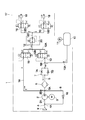
- FIG. 2 is a pneumatic circuit diagram showing a state in which the regeneration on-off valve and the nozzle on-off valve in FIG. 1 are opened, and the moist air after the regeneration of the dryer is supplied to the cleaning nozzle on the supply side.
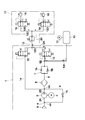
- FIG. 2 is a pneumatic circuit diagram showing a state in which the supply passage opening/closing valve and the nozzle opening/closing valve in FIG.
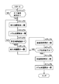
- It is a control block diagram of a compressed air supply device including a controller. It is a flow chart showing air cleaning processing by a controller.
- It is a pneumatic circuit diagram which shows the whole structure of the compressed air supply apparatus by 2nd Embodiment.
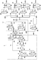
- It is a pneumatic circuit diagram which shows the whole structure of the compressed air supply apparatus by 3rd Embodiment.
- FIGS. 1 to 7 of the accompanying drawings taking as an example a case where the compressed air supply device is used for air cleaning of cameras/sensors mounted on a vehicle. ..
- FIGS. 1 to 5 show a first embodiment.
- the compressor device 1 is a device that compresses air and supplies compressed air to a supply target side 17 (cleaning nozzle 18) described later.
- the compressor device 1 constitutes a main part of the compressed air supply device.
- the compressor device 1 includes a compressor 2 as a compressor body, an electric motor 3 as a drive source for driving and stopping the compressor 2, and an intake pipe connected to a suction side 2A (hereinafter referred to as intake side 2A) of the compressor 2.
- a line 4 a supply/discharge pipe line 5 connected to the discharge side 2B of the compressor 2, a dryer (hereinafter referred to as an air dryer 6) provided in the supply/discharge pipe line 5, a bypass pipe line 8 described later, and an intake filter.
- the compressor 2 as the compressor body produces compressed air while sucking air from the intake side 2A.
- the compressor 2 is composed of, for example, a reciprocating compressor or a scroll compressor. Compressed air generated from the compressor 2 is stored in the tank 10 described later.
- the compressor 2 is rotationally driven by an electric motor 3 as a drive source. Driving and stopping of the electric motor 3 are controlled by a controller 21 (see FIG. 4) described later.
- An intake pipe line 4 is connected to the intake side 2A of the compressor 2.
- a supply/discharge pipe line 5 is connected to the discharge side 2B of the compressor 2.
- One end of the supply/discharge pipe line 5 is connected to the discharge side 2B of the compressor 2.
- the other end of the supply/discharge pipe line 5 is connected to a tank 10 and a supply line opening/closing valve 13 described later.
- An air dryer 6 and a pressure reducing valve 7 are provided in the middle of the supply/discharge pipe line 5.
- the intake pipe line 4 constitutes the intake passage of the compressor 2.
- a bypass conduit 8 to be described later is connected to the position of the connection point 4A of the intake conduit 4.
- the supply/discharge pipe line 5 constitutes a supply/discharge passage for supplying/discharging the compressed air generated from the compressor 2 to/from a tank 10 described later.
- the compressed air stored in the tank 10 is discharged through the supply/discharge pipe line 5, the compressed air is discharged from the tank 10 in a direction in which the air dryer 6 flows backward.
- the supply passage opening/closing valve 13 described later is opened, the dry compressed air in the tank 10 is discharged (supplied) from the supply/discharge pipe passage 5 to the supply passage 12 side.
- bypass line 8 which bypasses the compressor 2 and connects the two.
- One end of the bypass pipeline 8 is connected to the supply/discharge pipeline 5 so as to branch from the supply/discharge pipeline 5 at the connection point 5A.
- the other end of the bypass conduit 8 is connected to the intake conduit 4 so as to branch from the intake conduit 4 at the position of the connection point 4A.
- the connection point 5A is a position between the discharge side 2B of the compressor 2 and the air dryer 6, and connects the supply/discharge pipe line 5 to the bypass pipe line 8.
- a relief valve 16 described later is provided in the middle of the bypass pipe line 8.
- An intake filter 9 that opens to the outside of the compressor 2 and removes dust and the like in the air is provided on one end side of the intake pipe line 4 of the compressor 2.
- the other end of the intake pipe line 4 is connected to the intake side 2A of the compressor 2.
- An intake valve (not shown) is provided on the intake side 2A of the compressor 2 (or in the middle of the intake pipe line 4) to allow outside air to be sucked into the intake side 2A when the compressor 2 is driven.
- This intake valve is composed of a check valve that allows the outside air (air) to flow toward the compressor 2 and blocks the reverse flow.
- the air dryer 6 constitutes air drying means (dryer) provided in the middle of the supply/discharge pipe line 5.
- the air dryer 6 contains, for example, a moisture absorbent such as silica gel or a desiccant (not shown).
- the air dryer 6 is arranged between the discharge side 2B of the compressor 2 and the pressure reducing valve 7.
- the pressure reducing valve 7 is composed of a parallel circuit of a throttle 7A and a check valve 7B.
- the pressure reducing valve 7 does not open the check valve 7B to reduce the flow rate of the compressed air with respect to the forward flow described later. However, the pressure reducing valve 7 closes the check valve 7B against the flow in the reverse direction. Since the flow rate of the compressed air at this time is throttled by the throttle 7A, the air inside the air dryer 6 is depressurized and flows backward.
- the air dryer 6 brings the compressed air into contact with the desiccant therein, thereby converting the compressed air into a desiccant. Water is adsorbed and dried compressed air is supplied toward the tank 10.
- the compressed air discharged from the tank 10 flows in the air dryer 6 (supply/discharge pipe line 5) in the opposite direction, the dried compressed air (dry air) depressurizes the air dryer 6 and flows backward.
- the desiccant in the air dryer 6 is desorbed by the dry air.
- the desiccant of the air dryer 6 is regenerated and returned to a state capable of absorbing water again.
- the tank 10 forms a storage chamber that stores compressed air inside.
- the tank 10 has a connecting pipe 10A made of, for example, a flexible hose.
- One end of the connecting pipe 10A is detachably connected to the tank 10.
- the other end of the connection pipe 10A is connected to the supply/discharge pipe line 5 at a connection point 5B.
- the compressed air discharged from the compressor 2 flows through the supply/discharge pipe line 5 in the forward direction in a state dried by the air dryer 6 (that is, a state of dry air), and flows from the position of the connection point 5B to the connection pipe 10A. It is stored in the tank 10 via.
- the tank 10 is provided with a pressure sensor 11.
- the pressure sensor 11 detects the pressure in the tank 10 and outputs the detection signal to the controller 21, which will be described later.
- the supply passage 12 supplies compressed air to a supply target side 17 (cleaning nozzle 18) described later.
- the supply passage 12 is connected to the internal pipe passage 12A disposed in the compressor device 1, one end portion of which is connected to the internal pipe passage 12A at the position of the connection point 12B, and the other end portion of which is outside the compressor device 1 (
- the extended pipeline 12C extending to the supplied side 17), and a plurality of branch pipelines 12D branched from the tip end side of the extended pipeline 12C and connected to a cleaning nozzle 18 of the supplied side 17 described later. It is configured to include and.
- the supply passage opening/closing valve 13 is composed of, for example, a 2-port/2-position electromagnetic switching valve (solenoid valve).
- the supply passage opening/closing valve 13 is normally in the closed position (a) (in a demagnetized state).
- the supply passage opening/closing valve 13 is switched from the valve closing position (a) to the valve opening position (b) when excited by a control signal from the controller 21.
- the supply passage opening/closing valve 13 switched to the valve opening position (b) supplies the compressed air (dry air) in the tank 10 in a dry state from the supply/discharge pipe passage 5 to the supply passage 12(. It is supplied to the supply target side 17, which will be described later, via the internal conduit 12A). At this time, dry air from a cleaning nozzle 18, which will be described later, is jetted toward an object to be cleaned (for example, cameras/sensors mounted on the vehicle).
- the supply passage opening/closing valve 13 is an on/off type solenoid valve having a closed position (a) and an open position (b).
- a highly versatile electromagnetic switching valve can be adopted, and an expensive valve such as a three-way electromagnetic valve can be dispensed with.
- the one end of the regeneration passage 14 branches from the supply/discharge pipe 5 at the position of the connection point 5A (that is, between the compressor 2 and the air dryer 6).
- the other end of the regeneration passage 14 is connected to the supply passage 12 at the position of the connection point 12B.
- the regeneration passage 14 is provided with a regeneration on-off valve 15 that allows compressed air (wet air) to flow from at least the branch (that is, the position of the connection point 5A) toward the supply passage 12. There is.
- the regeneration on-off valve 15 is normally in the closed position (c).
- the regeneration opening/closing valve 15 is switched from the valve closing position (c) to the valve opening position (d) when excited by a control signal from the controller 21.
- the regeneration opening/closing valve 15 switched to the valve opening position (d) allows the dry air in the tank 10 to flow backward in the air dryer 6 along the arrow in FIG. Therefore, the desiccant in the air dryer 6 is regenerated by desorption of moisture by the dry air at this time, and is returned to a state capable of absorbing moisture again.
- the compressed air that has regenerated the desiccant in the air dryer 6 becomes compressed air in a non-dried state (that is, moist air), and flows from the position of the connection point 5A in the regeneration passage 14 in the direction of the arrow in FIG. Then, it is supplied into the supply passage 12 via the regeneration opening/closing valve 15.
- the moist air thus circulated from the regeneration passage 14 into the supply passage 12 via the regeneration opening/closing valve 15 is supplied to the supply-side 17 described later via the supply passage 12. Then, the moist air (non-dried compressed air) is jetted toward the object to be cleaned from the cleaning nozzle 18 described later.
- the regeneration opening/closing valve 15 is an on/off type electromagnetic valve having a closed position (c) and an open position (d).
- the regenerative on-off valve 15 can be a solenoid valve that has high versatility, and an expensive valve such as a three-way solenoid valve can be dispensed with.
- the relief valve 16 is provided in the bypass line 8. When the pressure on the discharge side 2B of the compressor 2 and/or the connection point 5A rises above a predetermined relief set pressure, the relief valve 16 is opened in order to relieve the excess pressure at this time. This can prevent the compressor 2 from being damaged by excessive pressure.
- the supplied side 17 is located outside the compressor device 1.
- the supply target side 17 is connected to the internal conduit 12A of the compressor device 1 or the regeneration passage 14 via the extension conduit 12C of the supply conduit 12 and the like.
- the supplied side 17 injects cleaning air toward, for example, a camera/sensor (not shown) mounted on the vehicle, so that the supply side 12 is connected to the tip side of each branch conduit 12D for cleaning. It is configured to include a member (a plurality of cleaning nozzles 18 ), a nozzle opening/closing valve 19 and a pressure regulator 20.
- the plurality of nozzle on-off valves 19 are provided in the middle of each branch conduit 12D in order to control the supply and discharge of compressed air to and from the cleaning nozzle 18.
- the nozzle opening/closing valve 19 is formed of, for example, an electromagnetic switching valve (solenoid valve) having two ports and two positions.
- the nozzle opening/closing valve 19 is normally in the valve closing position (e).
- the nozzle opening/closing valve 19 is switched from the valve closing position (e) to the valve opening position (f) when excited by a control signal from a controller 21 described later.
- the nozzle opening/closing valve 19 is returned to the closed position (e), the air injection from the cleaning nozzle 18 is stopped.
- a highly versatile electromagnetic switching valve can be adopted as the nozzle opening/closing valve 19, like the supply passage opening/closing valve 13 and the regeneration opening/closing valve 15, a highly versatile electromagnetic switching valve can be adopted.
- the nozzle opening/closing valve 19 may be provided so as to be connected between the cleaning nozzle 18 and the branch conduit 12D. It should be noted that the branch conduit 12D, the cleaning nozzle 18, and the nozzle on-off valve 19 may be provided, for example, in three or more pieces, or in a single (one) piece.
- the pressure regulator 20 is a pneumatic device (for example, a pressure reducing valve) that adjusts the pressure of the compressed air flowing in the extended pipe 12C of the supply passage 12.
- the pressure of the compressed air (wet air or dry air) ejected from the cleaning nozzle 18 is adjusted by the pressure regulator 20 so that the pressure is reduced to fall within a predetermined pressure range.
- the controller 21 as a control device is composed of, for example, a microcomputer. As shown in FIG. 4, the pressure sensor 11 and the operation switch 22 are connected to the input side of the controller 21.
- the operation switch 22 is manually operated by an operator when performing the air cleaning process shown in FIG. 5, for example. As a result, the air cleaning process shown in FIG. 5 is started. Further, the operation switch 22 is not manually operated by the operator, but is automatically turned on/off by a detection signal from another controller (neither is shown) when, for example, a stain on a cleaning target is detected by a dedicated sensor.
- the air cleaning process shown in FIG. 5 may be started or ended by being operated.
- the output side of the controller 21 is connected to the electric motor 3 of the compressor 2, the supply passage opening/closing valve 13, the regeneration opening/closing valve 15, the plurality of nozzle opening/closing valves 19, and the like.
- the controller 21 has a memory 21A including a ROM, a RAM, a non-volatile memory and the like.
- the memory 21A stores, for example, an air cleaning process program shown in FIG. 5 and a threshold value (predetermined time) for the determination process of step 4 shown in FIG.
- the controller 21 controls the drive of the electric motor 3 based on signals from the pressure sensor 11 and the operation switch 22. In addition to this, the controller 21 outputs a control signal to the supply passage opening/closing valve 13, the regeneration opening/closing valve 15, the nozzle opening/closing valve 19 and the like, and these valves 13, 15, 19 (specifically, each solenoid). ) Are individually excited or demagnetized. As a result, the supply passage opening/closing valve 13 is switched to either the valve closing position (a) or the valve opening position (b) shown in the drawing, and the regeneration opening/closing valve 15 and the nozzle opening/closing valve 19 are also set to any of the above. It can be switched to the position.
- the compressed air supply device has the above-described configuration, and its operation will be described next.
- the compressed air supply device drives the compressor 2 by the electric motor 3 shown in FIG. 1 to discharge the compressed air into the supply/discharge pipe line 5.
- the air dryer 6 adsorbs moisture by bringing the high-pressure compressed air into contact with the desiccant inside, and the compressed air is dried. Air is stored in the tank 10.
- the pressure in the tank 10 is detected by the pressure sensor 11.
- the pressure in the tank 10 reaches a predetermined high pressure side threshold value
- the driving of the compressor 2 by the electric motor 3 is stopped, and the compression operation is stopped.
- the pressure in the tank 10 decreases to, for example, a predetermined low-pressure side threshold value
- driving of the compressor 2 by the electric motor 3 is restarted. Therefore, the pressure in the tank 10 is maintained in the pressure range between the low pressure side threshold value and the high pressure side threshold value described above.
- step 1 when the control process of FIG. 5 starts, it is determined in step 1 whether or not the air cleaning is executed. For example, when the operation switch 22 is automatically or manually turned on to start air cleaning, it is determined to be “YES” in step 1 and the process proceeds to step 2. While the determination in step 1 is "NO", the next switch operation is awaited.
- step 2 the regeneration on-off valve 15 is switched from the closed position (c) to the open position (d) in order to start the air cleaning.
- step 3 the nozzle opening/closing valve 19 is switched from the valve closing position (e) to the valve opening position (f). Therefore, the compressed air in the tank 10 flows in the reverse direction in the air dryer 6 (supply/discharge pipe line 5) along the arrow in FIG. At this time, the dried compressed air is decompressed and flows backward in the air dryer 6. Therefore, the desiccant in the air dryer 6 is desorbed by the dry air. As a result, the desiccant in the air dryer 6 is regenerated and returned to a state capable of absorbing water again.
- the compressed air that has regenerated the desiccant in the air dryer 6 becomes compressed air in a non-dried state (that is, moist air), and flows from the position of the connection point 5A in the regeneration passage 14 in the direction of the arrow in FIG. Then, it is supplied into the supply passage 12 via the regeneration opening/closing valve 15.
- the moist air supplied from the regeneration passage 14 into the supply passage 12 through the regeneration opening/closing valve 15 is supplied to the branch passages 12D of the supply passage 12 and the nozzle opening/closing valve 19. It is ejected from the cleaning nozzle 18 on the side 17 toward an object to be cleaned (for example, a camera/sensor mounted on the vehicle).
- step 4 it is determined whether or not a predetermined time has elapsed since the opening/closing valve 15 for regeneration was opened.
- This predetermined time can be changed to a time desired by an operator or a manager, for example. While the determination is "NO” in step 4, the process returns to step 2 and the subsequent processes are continued. Then, when it is determined to be "YES” in step 4, the desired amount of moist air is jetted and supplied to the object to be cleaned from the cleaning nozzle 18 over a predetermined time.
- the regeneration on-off valve 15 is switched from the open position (d) to the closed position (c) and closed.
- the injection of the moist air from the cleaning nozzle 18 is stopped.
- the compressed air in the tank 10 is stopped from flowing toward the inside of the air dryer 6 (supply/discharge pipe line 5) by closing the opening/closing valve 15 for regeneration, and the regeneration treatment of the desiccant in the air dryer 6 is also stopped.
- the supply passage opening/closing valve 13 is switched from the closed position (a) to the open position (b) and opened.
- the supply passage opening/closing valve 13 switched to the valve opening position (b) supplies the compressed air (dry air) in the tank 10 in a dry state from the supply/discharge pipe passage 5 to the supply passage 12(. Supply to the supply-side 17 via the internal conduit 12A). Therefore, the dry air is jetted toward the object to be cleaned from the cleaning nozzle 18 on the supply-side 17 via each branch conduit 12D of the supply path 12 and the nozzle opening/closing valve 19.
- step 7 it is determined whether or not a predetermined time has passed since the supply passage opening/closing valve 13 was opened. This predetermined time can be changed to a time desired by an operator or a manager, for example. While the determination is “NO” in step 7, the process returns to step 6 and the subsequent processes are continued.
- the supply path opening/closing valve 13 is opened to the open position (step 8) in the next step 8.
- the valve is closed by switching from b) to the valve closing position (a).
- step 9 the nozzle opening/closing valve 19 is switched from the valve opening position (f) to the valve closing position (e) to be closed, whereby the controller 21 ends the air cleaning process.
- the compressed air supply apparatus has a compressor 2 for compressing air, an air dryer 6 having one side connected to the discharge side 2B of the compressor 2 for removing water in the air, and the other side of the air dryer 6.
- a storage chamber (tank 10) which is connected to the air dryer 6 and stores the compressed dry air after passing through the air dryer 6; doing.
- a regeneration passage 14 which is branched from a pipe (connection point 5A of the supply/discharge pipe passage 5) between the air dryer 6 and the compressor 2 and is connected to the supply passage 12. Is provided with at least a regeneration opening/closing valve 15 that allows the moist air after the dryer regeneration to flow from at least the branch (connection point 5A) toward the supply path 12.
- the supply passage opening/closing valve 13 is opened while the regeneration opening/closing valve 15 is closed.
- the compressed compressed air (dry air) from the tank 10 is supplied from the supply path 12 to the supply side 17. Moreover, the method similar to this is also adopted.
- the damp air after regeneration of the dryer is not released into the atmosphere and discarded, but is sprayed from the washing nozzle 18 of the supply-side 17 toward the washing target object. It is possible to make use of it in the cleaning work, and it is possible to prevent the compressed air from being exhausted unnecessarily. Then, after the moist air (regenerated air) is supplied to the cleaning nozzle 18 to clean the object, the last dry air is jetted from the cleaning nozzle 18 to the object, so that the object to be cleaned is effectively dried. Can be made. In addition, it is possible to prevent rusting of the nozzles and regulators and blockage due to freezing.
- the supply passage opening/closing valve 13 is opened to dry the compressed air in the tank 10. Air (dry air) is supplied from the supply path 12 to the cleaning nozzle 18 on the supplied side 17. Therefore, the object to be cleaned can be cleaned in a state where it is wet with the regenerated air and in a state where the dirt component adhering to the surface is wet. On this, the object can be washed with dry air so as to be dried, and the dirt of the object (camera washing or the like) can be easily removed.
- the supply passage opening/closing valve 13 is provided in the supply passage 12 for supplying the compressed air (dry air) from the tank 10 to the supplied side 17, and the regeneration passage 14 is provided from the supply passage opening/closing valve 13. Is also connected to the supply side 17 on the upstream side. Therefore, the regeneration air (wet air) passing through the regeneration passage 14 does not pass through the supply passage opening/closing valve 13 and the supply passage opening/closing valve 13 can be kept in a dry state, so that the occurrence of rust or the like is suppressed. be able to.
- the compressed air supply device is connected to the controller 21 as a control device, and the controller 21 opens the regeneration opening/closing valve 15 when the compressor 2 is not driven to dry the air dryer 6.
- the air that has regenerated the agent is circulated to the supply target side 17.
- the supply opening/closing valve 13 is opened after the regeneration opening/closing valve 15 is closed, and the compressed air in the tank 10 or the compressed air compressed by the compressor 2 is supplied toward the supplied side 17. ..
- the supply side 17 is provided with a cleaning member (that is, a cleaning nozzle 18) for cleaning the lenses and sensors (not shown) of the vehicle-mounted camera mounted on the vehicle body.
- the dry air accumulated in the tank 10 or the compressed air compressed by the compressor 2 is reduced in pressure by the pressure regulator 20 through the supply passage 12, and the nozzle opening/closing valve 19 is used. It is sprayed from the cleaning nozzle 18 to the target object (vehicle-mounted camera or the like). At this time, the moisture-containing air from the previous operation (opening and closing of the regeneration opening/closing valve 15) is swept away by the dry air.
- the compressed air stored (accumulated) in the tank 10 can be used for cleaning the object without waste. Further, after the air containing water is supplied to the target object, the dry air is finally supplied to the target object, so that it is possible to prevent the supply passage 12 (pipe) from being frozen, blocked, or rusted. Furthermore, by supplying air containing water to the target object, the dirt can be floated, and finally dry air can be supplied to the target object to remove water from the in-vehicle camera, sensors, etc., and perform effective cleaning. be able to. Note that the regeneration on-off valve 15 can be prevented from rusting and freezing by being attached to a high temperature component such as a cylinder head (not shown).
- FIG. 6 shows a second embodiment.
- a feature of this embodiment is that the supply passage opening/closing valve provided in the supply passage and the regeneration opening/closing valve provided in the regeneration passage are configured by one control valve (three-way valve).
- the same components as those in the first embodiment described above are designated by the same reference numerals, and the description thereof will be omitted.
- the directional control valve 31 employed in the second embodiment is a three-way valve configured so that the supply passage opening/closing valve 13 and the regeneration opening/closing valve 15 described in the first embodiment are combined into one control valve. It is a valve.
- the directional control valve 31 is normally in the first position (g).
- the directional control valve 31 is switched from the first position (g) to the second position (h) when excited by a control signal from the controller 21, for example. That is, in the first position (g), the supply/discharge pipe line 5 (further, the tank 10) is connected to the internal pipe line 32A of the supply passage 32, and the regeneration passage 14 is closed by the directional control valve 31 so that air flows. Is cut off.
- the regeneration passage 14 is connected to the internal pipe 32A of the supply passage 32, and the supply/discharge pipe 5 and the tank 10 are The flow of air toward the supply path 32 is blocked and blocked by the direction control valve 31.
- the supply path 32 for supplying the compressed air to the supply target side 17 (cleaning nozzle 18) has substantially the same structure as the supply path 12 described in the first embodiment, and is arranged in the compressor device 1.
- the one end of the internal conduit 32A of the supply conduit 32 is selectively connected to either the supply/discharge conduit 5 or the regeneration conduit 14 via the directional control valve 31.
- the directional control valve 31 When the directional control valve 31 is in the first position (g), the supply/discharge pipe line 5 (further, the tank 10) is connected to the internal pipe line 32A of the supply line 32. Then, the regeneration passage 14 is closed by the direction control valve 31 and the air flow is blocked.
- the nozzle opening/closing valve 19 when the nozzle opening/closing valve 19 is opened, the compressed compressed air (dry air) in the tank 10 is supplied from the supply/discharge pipe line 5 to the supply line 32 (internal pipe line 32A, extended pipe line). It is supplied to the cleaning nozzle 18 on the supplied side 17 via 32B and each branch pipe 32C). At this time, dry air is jetted from the cleaning nozzle 18 toward the object to be cleaned, so that the object can be cleaned with air.
- the nozzle opening/closing valve 19 is returned from the valve opening position (f) to the valve closing position (e), the air injection from the cleaning nozzle 18 is stopped and the air cleaning of the target object is stopped.
- the regeneration passage 14 becomes the internal conduit 32A of the supply passage 32. Connected. Then, the supply/discharge pipe path 5 and the tank 10 are blocked (blocked) by blocking the flow of air toward the supply path 32 side by the direction control valve 31.
- the compressed air in the tank 10 is circulated in the reverse direction into the air dryer 6 (supply/discharge pipe line 5), and the desiccant in the air dryer 6 is regenerated.
- the compressed air that has regenerated the desiccant flows from the position of the connection point 5A into the regeneration passage 14 and is switched to the second position (h). It is supplied into the supply path 32 via.
- the nozzle opening/closing valve 19 is switched from the closed position (e) to the open position (f)
- the air is jetted from the cleaning nozzle 18 on the supply-side 17 toward the cleaning target through the branch conduits 32C of the supply channel 32 and the nozzle opening/closing valve 19 to clean the target with air. It can be carried out.
- the dry air can be finally supplied to the object. Similar to the form, effective air cleaning can be performed.
- the directional control valve 31 serving as a three-way valve is adopted so that the supply passage opening/closing valve 13 and the regeneration opening/closing valve 15 described in the first embodiment are integrated into one control valve. ing. Therefore, the number of solenoid valves (solenoids) can be reduced and reliability can be improved.
- FIG. 7 shows a third embodiment.
- the feature of the compressed air supply device according to the present embodiment is that, in addition to the supplied side to be cleaned, compressed air is supplied to the air spring of the air suspension whose vehicle height can be adjusted, and the compressed air is discharged from the air spring. It is in the composition.
- the same components as those in the first embodiment described above are designated by the same reference numerals, and the description thereof will be omitted.
- a total of four air suspensions 41 are provided on the left front wheel (FL), right front wheel (FR), left rear wheel (RL), and right rear wheel (RR) side of the vehicle, and on each axle side and vehicle body It is provided between the side (not shown).
- These air suspensions 41 adjust the vehicle height according to expansion and contraction of the air chamber 41C by supplying and discharging compressed air into the air chamber 41C described later.
- Each of the air suspensions 41 includes, for example, a cylinder 41A mounted on the axle side of the vehicle, a piston rod 41B projecting from the inside of the cylinder 41A so as to be capable of expanding and contracting in the axial direction, and a projecting end side attached to the vehicle body side, and the piston rod 41B. It is configured by an air chamber 41C that is provided between the protruding end side and the cylinder 41A so as to be expandable and contractible and operates as an air spring.
- the air chamber 41C of each air suspension 41 is expanded/contracted in the axial direction by supplying/discharging compressed air from a branch conduit 42A described later.
- the piston rod 41B expands and contracts in the cylinder 41A in the axial direction to adjust the vehicle height (vehicle height) according to the supply/discharge amount of the compressed air.
- the air chamber 41C of the air suspension 41 is connected to the supply/discharge pipe line 5 of the compressor 2 via an air conduit 42.
- the base end side (one side) of the air conduit 42 is connected to the supply/discharge pipe line 5 at a position of a connection point 5B, for example.
- a plurality of (for example, four) branch conduits 42A are provided so as to branch from each other.
- the tip end side of each branch conduit 42A is detachably connected to the air chamber 41C of the air suspension 41.
- a supply/exhaust valve 43 for controlling the supply/discharge of compressed air to/from the air chamber 41C of the air suspension 41 is provided in the middle of each branch conduit 42A.
- Each of the supply/exhaust valves 43 is composed of, for example, a 2-port/2-position electromagnetic switching valve (solenoid valve).
- the supply/exhaust valve 43 is normally in the valve closed position (i).
- the supply/exhaust valve 43 is switched from the valve closed position (i) to the valve open position (j) when excited by a control signal from the controller 21 (see FIG. 4).
- each supply/exhaust valve 43 may be provided so as to be connected between the air chamber 41C of the air suspension 41 and the branch conduit 42A. Further, the supply/exhaust valve 43 has a function as a relief valve (safety valve). Therefore, when the pressure in the air chamber 41C exceeds the relief setting pressure, even if the supply/exhaust valve 43 remains demagnetized, it is temporarily switched from the closed position (i) to the open position (j) as a relief valve, The excess pressure at this time can be released into the air conduit 42.
- a highly versatile electromagnetic switching valve can be adopted as each supply/exhaust valve 43, as with the supply passage opening/closing valve 13 and the regeneration opening/closing valve 15, a highly versatile electromagnetic switching valve can be adopted. This also applies to the tank opening/closing valve 44 and the atmospheric release valve 46 described later.
- connection pipe 10A is connected to the air conduit 42 at the position of the connection point 42B, and the tank opening/closing valve 44 is provided in the middle of the connection pipe 10A.
- the tank opening/closing valve 44 is composed of, for example, a 2-port/2-position electromagnetic switching valve (solenoid valve).
- the tank opening/closing valve 44 is normally in the valve closing position (k).
- the tank opening/closing valve 44 is switched from the valve closing position (k) to the valve opening position (l).
- the tank opening/closing valve 44 may be provided so as to be connected between the tank 10 and the connection pipe 10A.
- the tank opening/closing valve 44 in the valve closed position (k) prevents compressed air in the tank 10 from flowing from the connecting pipe 10A to the air conduit 42 (supply/discharge pipe line 5), and the tank 10 to the outside. Shut off. However, when the tank opening/closing valve 44 is switched to the valve opening position (l), for example, compressed air from the compressor 2 (dry air dried by the air dryer 6) is connected to the supply/discharge pipe line 5, the air conduit 42, and the connection. Allowed to be stored in tank 10 via tube 10A. In addition, the dry compressed air in the tank 10 is allowed to flow (exhaust) from the connecting pipe 10A toward the air conduit 42 (supply/exhaust pipe line 5).
- a pressure sensor that is, a pressure detector 45 for detecting the pressure in each air chamber 41C or the tank 10 is provided.
- the pressure detector 45 opens and closes the tank open/close valve 44 from the closed position (k) with all the supply/exhaust valves 43, the supply passage open/close valve 13, the regeneration open/close valve 15, and the atmosphere release valve 46 closed.
- the pressure in the tank 10 can be detected via the connecting pipe 10A and the air conduit 42 when the valve opening position (l) is switched to.
- the supply passage opening/closing valve 13 the regeneration opening/closing valve 15, the tank opening/closing valve 44, and the atmosphere release valve 46 are closed, for example, when at least one of the supply/exhaust valve 43 is opened, the corresponding air suspension.
- the pressure in the air chamber 41C of 41 can be detected by the pressure detector 45.
- the air chambers 41C of all the air suspensions 41 communicate with each other, and the pressure inside the air chamber 41C in this state can be detected by the pressure detector 45.
- the atmosphere release valve 46 as an exhaust valve is provided in the bypass conduit 8 as a bypass passage that bypasses the front and rear of the compressor 2.
- the atmosphere release valve 46 is composed of, for example, a 2-port/2-position electromagnetic switching valve (solenoid valve).
- the atmosphere release valve 46 is normally placed in the closed position (m), and when excited by a control signal from the controller 21, it is switched from the closed position (m) to the open position (n).
- the air release valve 46 When the air release valve 46 is opened, the compressed air in the tank 10 is exhausted to the outside (released into the atmosphere) via the supply/discharge pipe line 5, the air dryer 6, and the bypass pipe line 8, or inside the air suspension 41.
- the compressed air can be exhausted to the outside (released to the atmosphere) via the supply/discharge pipe 5, the air dryer 6, and the bypass pipe 8.
- the desiccant in the air dryer 6 is regenerated as described above.
- the atmosphere release valve 46 has a function as a relief valve (safety valve) like the supply/exhaust valve 43 described above.
- the compressed air supply device is configured to supply the compressed air to the air chamber 41C of the air suspension 41 in addition to the supplied side 17 to be cleaned.
- the air supply device in this case is connected to a control device (for example, the controller 21 shown in FIG. 4), and the control device opens the regeneration opening/closing valve 15 when the compressor 2 is not driven and supplies the supply side 17 ( Air (wet air) regenerated from the air dryer 6 is supplied to the cleaning nozzle 18), and then the regeneration opening/closing valve 15 is closed and then the supply passage opening/closing valve 13 is opened to dry air in the tank 10.
- the compressed air (dry air) in the air suspension 41 (air chamber 41C) is supplied to the supply-side 17 via the supply path 12.
- the tank opening/closing valve 44 remains closed and the supply/exhaust valve 43 is opened.
- the air cleaning process shown in FIG. 5 first, the process of opening the supply opening/closing valve 13 after opening the regeneration opening/closing valve 15
- the air is released to the atmosphere every time the vehicle height is lowered. It is also possible to inject air from the cleaning nozzle 18 using the released air (that is, the air flowing through the regeneration on-off valve 15) to clean the air of the target object (vehicle-mounted camera or the like).
- the vehicle height adjustment by each air suspension 41 and the air cleaning of the object to be cleaned can be appropriately combined, and the single compressor device 1 can be used for the vehicle height adjustment work. It can be used together with air cleaning work and can be used in common. As a result, the vehicle-mounted air supply device can be made compact as a whole, and space and energy can be saved.
- the supply passage opening/closing valve 13, the regeneration opening/closing valve 15, the nozzle opening/closing valve 19, the supply/exhaust valve 43, the tank opening/closing valve 44, and the atmosphere release valve 46 are used as relief valves (safety valves).
- the description has been given by taking as an example the case where the configuration having the function of.
- the supply passage opening/closing valve 13, the regeneration opening/closing valve 15, and/or the nozzle opening/closing valve 19 do not necessarily need to operate as a relief valve, and may be configured using an electromagnetic switching valve that does not have a relief function. Good.
- compressed air is supplied by compressing air, removing dried water by a drier, storing dried compressed air in a storage chamber, and supplying the dried compressed air to a supply destination side.
- An apparatus in which dried compressed air is circulated from the storage chamber side to the dryer, moist air that has regenerated the dryer is supplied to the supplied side, and then, dried compressed air is supplied to the supplied side. It is configured to supply.
- a second aspect is a compressed air supply method in which air is compressed, moisture is removed by a dryer, and then dried compressed air is stored in a storage chamber and the dried compressed air is supplied to a supply destination side. Then, dry compressed air is circulated from the storage chamber side to the dryer, the dryer is regenerated, the regenerated moist air is supplied to the supply side, and then the dried compressed air is supplied to the supply side. I am trying to supply it to.
- a compressed air supply device that compresses air and supplies the compressed air to the supply side, wherein a compressor that compresses air and one side is connected to the discharge side of the compressor, A dryer that removes water in the air, a storage chamber that is connected to the other side of the dryer and that stores the dried compressed air that has passed through the dryer, and a supply that supplies the dry air of the storage chamber to the supply destination side. And a regeneration passage that branches from a pipe between the dryer and the compressor and is connected to the supply passage, the regeneration passage having at least the air flowing from the branch toward the supply passage. It is characterized by the provision of an on-off valve for regeneration that enables the circulation of
- a supply passage opening/closing valve that opens/closes the supply passage is provided in the supply passage, and the regeneration passage is located closer to the supply side than the supply passage opening/closing valve. It is characterized by being connected to the upstream side.
- a fifth aspect is characterized in that, in the fourth aspect, the supply passage opening/closing valve and the regeneration opening/closing valve are one control valve.
- the compressed air supply device is connected to a control device, and the control device opens the regeneration on-off valve when the compressor is not driven. Valve, and discharges the air that has regenerated the dryer to the supplied side, and then closes the regeneration on-off valve and then supplies compressed air in the storage chamber or compressed air in the storage chamber to the supplied side. It is characterized by supplying.
- the compressed air supply device supplies compressed air to an air spring of an air suspension in addition to the supply side.
- the compressed air supply device is connected to a control device, and by the control device, the regeneration on-off valve is opened when the compressor is not driven, and the air regenerated by the dryer is supplied to the supply side. It is characterized in that the compressed air in the air spring is supplied to the supply side after discharging, and after closing the regeneration on-off valve.
- the supplied side is a cleaning member for cleaning a lens or a sensor of a camera attached to a vehicle body.
- Compressor device 1 Compressor device 2 Compressor 3 Electric motor 4 Intake pipe line 5 Supply and discharge pipe line 6 Air dryer (dryer) 10 tanks (storage room) 12, 32 Supply path 13 Supply path opening/closing valve 14 Regeneration path 15 Regeneration opening/closing valve 17 Supply side 18 Cleaning nozzle (cleaning member) 19 Nozzle on-off valve 20 Pressure regulator 21 Controller (control device) 31 Directional control valve (control valve) 41 air suspension 41C air chamber (air spring) 42 air conduit 43 air supply/exhaust valve 46 atmospheric release valve
Landscapes
- Engineering & Computer Science (AREA)
- Mechanical Engineering (AREA)
- Chemical & Material Sciences (AREA)
- General Engineering & Computer Science (AREA)
- Analytical Chemistry (AREA)
- General Chemical & Material Sciences (AREA)
- Oil, Petroleum & Natural Gas (AREA)
- Chemical Kinetics & Catalysis (AREA)
- Drying Of Gases (AREA)
Abstract
圧縮空気供給装置は、空気を圧縮するコンプレッサ(2)と、コンプレッサ(2)の吐出側(2B)に一側が接続され、空気中の水分を除去するエアドライヤ(6)と、エアドライヤ(6)の他側に接続され、エアドライヤ(6)を通過して乾燥した圧縮空気を貯留するタンク(10)と、タンク(10)内の乾いた空気を排出して被供給側(17)に供給する供給路(12)と、を有している。再生通路(14)は、エアドライヤ(6)とコンプレッサ(2)との間の給排管路(5)の接続点(5A)から分岐されて供給路(12)に接続されている。再生通路(14)には、少なくとも接続点(5A)から供給路(12)に向けてドライヤ再生後の湿った空気が流通するのを可能とする再生用開閉弁(15)が設けられている。
Description
本開示は、例えば車両に搭載されるカメラレンズまたはセンサ類等の対象物を圧縮空気で洗浄するようにした圧縮空気供給装置及び圧縮空気供給方法に関する。
近年、運転支援カメラや自動運転のためのセンサ類を搭載した車両が増加の傾向にある。これらのカメラ、センサ類には、大気中のダストや汚れ等が付着し易いので、車載カメラのレンズやセンサ類の検出部表面を圧縮空気等で洗浄するニーズが高まっている。圧縮空気による洗浄装置としては、例えば特許文献1,2に開示された従来技術が知られている。特許文献1には、自動車カメラのレンズをエア洗浄する装置が記載されている。特許文献2には、自動車用バックモニタ装置のカメラレンズを洗浄する装置が記載されている。
ここで、特許文献1,2に開示されたように、対象物をエア洗浄する場合には、例えばコンプレッサで圧縮した空気をタンク等に一度貯溜し、この貯溜した圧縮空気を対象物に向けて吹付けるように供給する。しかし、空気を圧縮すると、露点温度が上がり、空気中の水分が結露して水滴となる。このため、タンクに水が溜まり、ノズルやレギュレータ等に水分が付着し、錆の発生原因となる恐れがある。また、氷点下の温度状態では、水滴が凍結し閉塞等の問題が起きることがある。このため、乾燥剤を封入したエアドライヤを通して圧縮空気を乾燥させ、乾燥状態の圧縮空気をタンク内に貯溜するようにしている。
ところで、前記エアドライヤは、乾燥剤の飽和を防ぐために、タンク内の乾いた空気を定期的に戻して乾燥剤を再生させる工程が必要になる。このとき、エアドライヤを逆に通過し、乾燥剤を再生させた湿った空気は、大気中に開放、排出され、せっかく圧縮した空気を捨ててしまう。そこで、本発明者等は、乾燥剤を再生させた後の空気(湿った空気)を、エア洗浄にも用いることを検討した。しかし、カメラレンズ等の洗浄対象物に再生後の湿った空気を吹き付けると、対象物に水滴が付着したり、前述同様にノズルやレギュレータ等に錆の発生や凍結による閉塞等の問題がある。
本発明の一実施形態の目的は、対象物(被供給側)への圧縮空気の供給を効率的に行うことができるようにした圧縮空気供給装置及び圧縮空気供給方法を提供することにある。
本発明の一実施形態は、空気を圧縮し、ドライヤによって水分を除去した後に貯留室に乾燥した圧縮空気を貯留し、被供給側に該乾燥した圧縮空気を供給する圧縮空気供給装置であって、前記ドライヤに貯留室側から乾燥した圧縮空気を流通させて、前記ドライヤを再生させた湿った空気を前記被供給側に供給し、その後、乾燥した圧縮空気を被供給側に供給する。
本発明の一実施形態は、空気を圧縮し、ドライヤによって水分を除去した後に貯留室に乾燥した圧縮空気を貯留し、被供給側に該乾燥した圧縮空気を供給する圧縮空気供給方法であって、前記ドライヤに貯留室側から乾燥した圧縮空気を流通させて、前記ドライヤを再生し、再生させた湿った空気を前記被供給側に供給し、その後、乾燥した圧縮空気を前記被供給側に供給する。
本発明の一実施形態は、空気を圧縮し、被供給側に該圧縮空気を供給する圧縮空気供給装置であって、空気を圧縮するコンプレッサと、前記コンプレッサの吐出側に一側が接続され、空気中の水分を除去するドライヤと、前記ドライヤの他側に接続され、前記ドライヤ通過後の乾燥した圧縮空気を貯留する貯留室と、前記貯留室の乾燥空気を前記被供給側に供給する供給路と、を有し、前記ドライヤと前記コンプレッサとの間の配管から分岐されて前記供給路に接続される再生通路を備え、該再生通路には、少なくとも前記分岐から前記供給路に向けて空気の流通を可能とする再生用開閉弁を設けたことを特徴としている。
本発明の一実施形態によれば、再生空気(湿った空気)を被供給側に供給するため、例えば洗浄対象物の汚れ等を落とし易くできる。そして、再生空気を供給した後に、乾いた空気を被供給側に供給するため、凍結による閉塞、錆などの発生を抑えることができる。
以下、本発明の実施形態による圧縮空気供給装置を、車両に搭載されたカメラ/センサ類のエア洗浄に用いる場合を例に挙げ、添付図面の図1ないし図7を参照して詳細に説明する。
ここで、図1ないし図5は第1の実施形態を示している。コンプレッサ装置1は、空気を圧縮して後述の被供給側17(洗浄ノズル18)に圧縮空気を供給する装置である。コンプレッサ装置1は、圧縮空気供給装置の主要部を構成している。コンプレッサ装置1は、コンプレッサ本体としてのコンプレッサ2と、該コンプレッサ2を駆動,停止する駆動源としての電動モータ3と、コンプレッサ2の吸込み側2A(以下、吸気側2Aという)に接続された吸気管路4と、コンプレッサ2の吐出側2Bに接続された給排管路5と、該給排管路5に設けられたドライヤ(以下、エアドライヤ6という)と、後述のバイパス管路8、吸気フィルタ9、供給路12の内部管路12A、供給路開閉弁13、再生通路14、再生用開閉弁15およびリリーフ弁16等と、を含んで構成されている。
コンプレッサ本体としてのコンプレッサ2は、その吸気側2Aから空気を吸込みつつ、圧縮空気を生成する。コンプレッサ2は、例えば往復動式圧縮機またはスクロール式圧縮機等により構成されている。コンプレッサ2から発生した圧縮空気は、後述のタンク10に貯留される。コンプレッサ2は、駆動源としての電動モータ3により回転駆動される。電動モータ3は、後述のコントローラ21(図4参照)により駆動,停止が制御される。
コンプレッサ2の吸気側2Aには、吸気管路4が接続されている。コンプレッサ2の吐出側2Bには、給排管路5が接続されている。この給排管路5の一端側は、コンプレッサ2の吐出側2Bに接続されている。給排管路5の他端側は、後述のタンク10と供給路開閉弁13とに接続されている。給排管路5の途中位置には、エアドライヤ6と減圧バルブ7とが設けられている。
吸気管路4は、コンプレッサ2の吸気通路を構成している。吸気管路4の接続点4Aの位置には、後述のバイパス管路8が接続されている。給排管路5は、コンプレッサ2から発生した圧縮空気を後述のタンク10に給排する給排通路を構成している。タンク10内に貯留された圧縮空気を給排管路5を介して排出する場合には、例えばエアドライヤ6を逆流する方向で圧縮空気はタンク10から排出される。後述の供給路開閉弁13を開弁した場合は、タンク10内の乾燥した圧縮空気が給排管路5から供給路12側に排出(供給)される。
また、コンプレッサ2の吸気側2Aと吐出側2Bとの間には、コンプレッサ2をバイパス(迂回)して両者間を接続するバイパス管路8が設けられている。このバイパス管路8の一方の端部は、接続点5Aの位置で給排管路5から分岐するように給排管路5に接続されている。バイパス管路8の他方の端部は、接続点4Aの位置で吸気管路4から分岐するように吸気管路4に接続されている。接続点5Aは、コンプレッサ2の吐出側2Bとエアドライヤ6との間となる位置で、給排管路5をバイパス管路8に接続している。バイパス管路8の途中には、後述のリリーフ弁16が設けられている。
コンプレッサ2の吸気管路4の一端側は、コンプレッサ2の外部に開口し空気中の塵埃等を除去する吸気フィルタ9が設けられている。吸気管路4の他端側は、コンプレッサ2の吸気側2Aに接続されている。なお、コンプレッサ2の吸気側2A(または、吸気管路4の途中)には、コンプレッサ2の駆動時に外気を吸気側2Aに吸込ませる吸気バルブ(図示せず)が設けられている。この吸気バルブは、コンプレッサ2に向けて外気(空気)が流通するのを許し、逆向きの流れを阻止する逆止弁により構成される。
エアドライヤ6は、給排管路5の途中に介装して設けられた空気乾燥手段(ドライヤ)を構成している。このエアドライヤ6は、例えばシリカゲル等の水分吸着剤または乾燥剤(図示せず)等を内蔵している。エアドライヤ6は、コンプレッサ2の吐出側2Bと減圧バルブ7との間に配設されている。減圧バルブ7は、絞り7Aとチェック弁7Bとの並列回路により構成されている。減圧バルブ7は、後述の順方向流れに対しては、チェック弁7Bが開弁して圧縮空気の流量を絞ることはない。しかし、減圧バルブ7は、逆方向の流れに対してはチェック弁7Bが閉弁する。このときの圧縮空気は、絞り7Aにより流量が絞られるため、エアドライヤ6内を減圧させて逆流する。
コンプレッサ2で発生した高圧の圧縮空気がタンク10に向けて給排管路5内を順方向に流通するときには、エアドライヤ6は、この圧縮空気を内部の乾燥剤に接触させることにより、乾燥剤に水分を吸着させ、乾燥した圧縮空気をタンク10に向けて供給する。一方、タンク10から排出された圧縮空気がエアドライヤ6(給排管路5)内を逆方向に流通するときには、乾燥した圧縮空気(乾いた空気)がエアドライヤ6内を減圧させて逆流する。この場合、エアドライヤ6内の乾燥剤は、この乾いた空気により水分が脱着される。これにより、エアドライヤ6の乾燥剤は、再生され、再び水分を吸着可能な状態に戻される。
タンク10は、内部に圧縮空気を貯留する貯留室を形成している。タンク10は、例えば可撓性ホース等からなる接続管10Aを有している。この接続管10Aの一方の端部は、タンク10に取外し可能に接続されている。接続管10Aの他方の端部は、給排管路5に接続点5Bの位置で接続されている。コンプレッサ2から吐出された圧縮空気は、エアドライヤ6により乾燥された状態(即ち、乾いた空気の状態)で給排管路5内を順方向に流通し、接続点5Bの位置から接続管10Aを介してタンク10内に貯留される。タンク10には、圧力センサ11が設けられている。この圧力センサ11は、タンク10内の圧力を検出し、その検出信号を後述のコントローラ21に出力する。
供給路12は、後述の被供給側17(洗浄ノズル18)に圧縮空気を供給する。供給路12は、コンプレッサ装置1内に配設された内部管路12Aと、一方の端部が接続点12Bの位置で内部管路12Aに接続され、他方の端部がコンプレッサ装置1の外部(被供給側17)へと延びた延設管路12Cと、該延設管路12Cの先端側から複数に分岐し後述する被供給側17の洗浄ノズル18に接続された複数の分岐管路12Dとを含んで構成されている。
供給路12の内部管路12Aの一端側は、供給路開閉弁13を介して給排管路5(さらには、タンク10)に接続されている。この供給路開閉弁13は、例えば2ポート2位置の電磁式切換弁(ソレノイドバルブ)により構成されている。供給路開閉弁13は、通常時(消磁状態で)は閉弁位置(a)におかれている。供給路開閉弁13は、コントローラ21からの制御信号により励磁されると、閉弁位置(a)から開弁位置(b)に切換えられる。
図3に示すように、開弁位置(b)に切換えられた供給路開閉弁13は、タンク10内の乾燥状態にある圧縮空気(乾いた空気)を給排管路5から供給路12(内部管路12A)を介して後述の被供給側17へと供給する。このとき、後述の洗浄ノズル18からの乾いた空気が、洗浄対象物(例えば、車両に搭載されたカメラ/センサ類)に向けて噴射される。
また、供給路開閉弁13は、閉弁位置(a)と開弁位置(b)とからなるオン・オフ式の電磁弁である。供給路開閉弁13は、汎用性の高い電磁式切換弁を採用することができ、例えば三方電磁弁のような高価な弁を不要にすることができる。
再生通路14の一方の端部は、接続点5Aの位置(即ち、コンプレッサ2とエアドライヤ6との間)で給排管路5から分岐している。再生通路14の他方の端部は、接続点12Bの位置で供給路12に接続されている。この再生通路14には、少なくとも前記分岐(即ち、接続点5Aの位置)から供給路12に向けて圧縮空気(湿った空気)が流通するのを可能にする再生用開閉弁15が設けられている。
再生用開閉弁15は、通常時は閉弁位置(c)におかれている。再生用開閉弁15は、コントローラ21からの制御信号により励磁されると、閉弁位置(c)から開弁位置(d)に切換えられる。開弁位置(d)に切換えられた再生用開閉弁15は、タンク10内の乾いた空気が図2中の矢印に沿ってエアドライヤ6内を逆流するのを許す。このため、エアドライヤ6内の乾燥剤は、このときの乾いた空気により水分が脱着されて再生され、再び水分を吸着可能な状態に戻される。そして、エアドライヤ6の乾燥剤を再生させた圧縮空気は、非乾燥状態の圧縮空気(即ち、湿った空気)となって、接続点5Aの位置から再生通路14内を図2の矢印方向に流通し、再生用開閉弁15を介して供給路12内へと供給される。
このように、再生通路14から再生用開閉弁15を介して供給路12内へと流通された湿った空気は、供給路12を介して後述の被供給側17へと供給される。そして、湿った空気(非乾燥の圧縮空気)は、後述の洗浄ノズル18から洗浄対象物に向けて噴射される。なお、再生用開閉弁15は、閉弁位置(c)と開弁位置(d)とからなるオン・オフ式の電磁弁である。再生用開閉弁15は、汎用性の高い電磁式切換弁を採用することができ、例えば三方電磁弁のような高価な弁を不要にすることができる。
リリーフ弁16は、バイパス管路8に設けられている。コンプレッサ2の吐出側2Bおよび/または接続点5Aの圧力が予め決められたリリーフ設定圧以上に昇圧すると、このときの過剰圧をリリーフさせるため、リリーフ弁16は、開弁される。これにより、コンプレッサ2が過剰圧で損傷されるのを防ぐことができる。
被供給側17は、コンプレッサ装置1の外側に位置している。被供給側17は、供給路12の延設管路12C等を介してコンプレッサ装置1の内部管路12A、または再生通路14に接続される。被供給側17は、例えば車両に搭載されたカメラ/センサ類(図示せず)に向けて洗浄用のエアを噴射するため、供給路12の各分岐管路12Dの先端側に接続された洗浄部材(複数の洗浄ノズル18)と、ノズル用開閉弁19および圧力レギュレータ20とを含んで構成されている。
複数のノズル用開閉弁19は、洗浄ノズル18に対する圧縮空気の給排を制御するため、各分岐管路12Dの途中にそれぞれ設けられている。ノズル用開閉弁19は、例えば2ポート2位置の電磁式切換弁(ソレノイドバルブ)により構成されている。ノズル用開閉弁19は、通常時は閉弁位置(e)におかれている。ノズル用開閉弁19は、後述するコントローラ21からの制御信号により励磁されると、閉弁位置(e)から開弁位置(f)に切換えられる。
開弁位置(f)に切換えられたノズル用開閉弁19は、供給路12から供給される圧縮空気(湿った空気または乾いた空気)を洗浄ノズル18から外部に向けて噴射させる。ノズル用開閉弁19が閉弁位置(e)に戻されたときには、洗浄ノズル18からのエア噴射が停止される。ノズル用開閉弁19は、供給路開閉弁13および再生用開閉弁15と同様に、汎用性の高い電磁式切換弁を採用することができる。
なお、各ノズル用開閉弁19は、洗浄ノズル18と分岐管路12Dとの間に接続して設ける構成でもよい。なお、分岐管路12D、洗浄ノズル18およびノズル用開閉弁19は、例えば3個以上設ける構成であってもよく、単数(1個)設ける構成としてもよい。
圧力レギュレータ20は、供給路12の延設管路12C内を流通する圧縮空気の圧力を調整する空気圧機器(例えば、減圧弁)である。洗浄ノズル18から噴射される圧縮空気(湿った空気または乾いた空気)の圧力は、圧力レギュレータ20により予め決められた圧力範囲に収まるように減圧して調整される。
制御装置としてのコントローラ21は、例えばマイクロコンピュータ等により構成されている。図4に示すように、コントローラ21の入力側には、圧力センサ11および操作スイッチ22等が接続されている。操作スイッチ22は、例えば図5に示すエア洗浄処理を行うときに、オペレータによって手動で操作される。これによって、図5に示すエア洗浄処理が開始される。また、操作スイッチ22は、オペレータの手動操作ではなく、例えば洗浄対象物の汚れを専用のセンサで検知した場合に、他のコントローラ(いずれも図示せず)からの検知信号により自動でON,OFF操作され、これによって、図5に示すエア洗浄処理が開始または終了される構成としてもよい。
コントローラ21の出力側は、コンプレッサ2の電動モータ3と、供給路開閉弁13、再生用開閉弁15および複数のノズル用開閉弁19等とに接続されている。また、コントローラ21は、ROM,RAM,不揮発性メモリ等からなるメモリ21Aを有している。このメモリ21Aには、例えば図5に示すエア洗浄処理用のプログラムと、図5に示すステップ4の判定処理用の閾値(所定時間)等とが更新可能に格納されている。
コントローラ21は、圧力センサ11および操作スイッチ22等からの信号に基づいて、電動モータ3の駆動制御を行う。これに加えて、コントローラ21は、供給路開閉弁13、再生用開閉弁15およびノズル用開閉弁19等に制御信号を出力し、これらの弁13,15,19(具体的には、各ソレノイド)を個別に励磁したり、消磁したりする。これにより、供給路開閉弁13は、図示の閉弁位置(a)と開弁位置(b)との何れかに切換えられ、再生用開閉弁15およびノズル用開閉弁19も、それぞれ何れかの位置に切換えられるものである。
第1の実施形態による圧縮空気供給装置は、上述の如き構成を有するもので、次に、その作動について説明する。
まず、タンク10内に圧縮空気を貯留するときには、圧縮空気供給装置は、図1に示す電動モータ3によりコンプレッサ2を駆動し、給排管路5内に圧縮空気を吐出する。この圧縮空気がタンク10に向けて給排管路5内を順方向に流通するときに、エアドライヤ6は、高圧の圧縮空気を内部の乾燥剤に接触させることにより水分を吸着し、乾燥した圧縮空気がタンク10内に貯留される。
タンク10内の圧力は、圧力センサ11で検出される。タンク10内の圧力が予め決められた高圧側の閾値に達すると、電動モータ3によるコンプレッサ2の駆動が止められ、圧縮運転は停止される。一方、タンク10から圧縮空気が排出され、タンク10内の圧力が、例えば予め決められた低圧側の閾値まで低下すると、電動モータ3によるコンプレッサ2の駆動(圧縮運転)が再開される。このため、タンク10内の圧力は、前述した低圧側の閾値と高圧側の閾値との間の圧力範囲に保たれる。
次に、図5を参照して、コントローラ21によるエア洗浄処理について説明する。即ち、図5の制御処理がスタートすると、ステップ1でエア洗浄を実行するか否かを判定する。例えば、操作スイッチ22が自動または手動でON操作されることにより、エア洗浄が開始されるときには、ステップ1で「YES」と判定されて次のステップ2に移る。ステップ1で「NO」と判定する間は、次なるスイッチ操作を待機する。
ステップ2の処理では、エア洗浄を開始するために再生用開閉弁15を閉弁位置(c)から開弁位置(d)に切換える。また、ステップ3では、ノズル用開閉弁19を閉弁位置(e)から開弁位置(f)に切換える。このため、タンク10内の圧縮空気は、図2中の矢印に沿ってエアドライヤ6(給排管路5)内を逆方向に流通する。このとき、乾燥した圧縮空気が減圧されてエアドライヤ6内を逆流する。このため、エアドライヤ6内の乾燥剤は、乾いた空気により水分が脱着される。これにより、エアドライヤ6の乾燥剤は再生され、再び水分を吸着可能な状態に戻される。
そして、エアドライヤ6の乾燥剤を再生させた圧縮空気は、非乾燥状態の圧縮空気(即ち、湿った空気)となって、接続点5Aの位置から再生通路14内を図2の矢印方向に流通し、再生用開閉弁15を介して供給路12内へと供給される。このように、再生通路14から再生用開閉弁15を介して供給路12内へと供給された湿った空気は、供給路12の各分岐管路12Dおよびノズル用開閉弁19を介して被供給側17の洗浄ノズル18から洗浄対象物(例えば、車両に搭載されたカメラ/センサ類)に向けて噴射される。
次に、ステップ4では、再生用開閉弁15を開弁してから所定時間が経過したか否かを判定する。この所定時間は、例えばオペレータまたは管理者等が所望する時間に変更可能である。ステップ4で「NO」と判定する間は、前記ステップ2の処理に戻り、これ以降の処理を続行する。そして、ステップ4で「YES」と判定したときには、前記洗浄対象物に対し洗浄ノズル18から湿った空気が所定時間にわたって所望量だけ噴射、供給されている。
そこで、次のステップ5では、再生用開閉弁15を開弁位置(d)から閉弁位置(c)に切換えて閉弁させる。これにより、洗浄ノズル18からの前記湿った空気の噴射は停止される。しかも、タンク10内の圧縮空気は、再生用開閉弁15の閉弁によりエアドライヤ6(給排管路5)内に向けた流通が停止され、エアドライヤ6の乾燥剤に対する再生処理も止められる。
この段階で、次のステップ6では、供給路開閉弁13を閉弁位置(a)から開弁位置(b)に切換えて開弁させる。図3に示すように、開弁位置(b)に切換えられた供給路開閉弁13は、タンク10内の乾燥状態にある圧縮空気(乾いた空気)を給排管路5から供給路12(内部管路12A)を介して被供給側17へと供給する。このため、乾いた空気は、供給路12の各分岐管路12Dおよびノズル用開閉弁19を介して被供給側17の洗浄ノズル18から前記洗浄対象物に向けて噴射される。
次のステップ7では、供給路開閉弁13を開弁してから所定時間が経過したか否かを判定する。この所定時間は、例えばオペレータまたは管理者等が所望する時間に変更可能である。ステップ7で「NO」と判定する間は、前記ステップ6の処理に戻り、これ以降の処理を続行する。そして、ステップ7で「YES」と判定したときには、前記洗浄対象物に対し洗浄ノズル18から乾いた空気が十分に噴射されているので、次のステップ8で供給路開閉弁13を開弁位置(b)から閉弁位置(a)に切換えて閉弁させる。そして、ステップ9では、ノズル用開閉弁19を開弁位置(f)から閉弁位置(e)に切換えて閉弁させ、これにより、コントローラ21はエア洗浄処理を終了させる。
この状態で、タンク10内の圧力が前記低圧側の閾値以下まで低下しているときには、電動モータ3によるコンプレッサ2の駆動(圧縮運転)が再開され、コンプレッサ2からの乾燥した圧縮空気がタンク10内に貯留される。そして、タンク10内の圧力が前記高圧側の閾値に達すると、電動モータ3によるコンプレッサ2の駆動が止められ、圧縮運転は停止される。
かくして、第1の実施形態による圧縮空気供給装置は、空気を圧縮するコンプレッサ2と、コンプレッサ2の吐出側2Bに一側が接続され、空気中の水分を除去するエアドライヤ6と、エアドライヤ6の他側に接続され、エアドライヤ6を通過して乾燥した圧縮空気を貯留する貯留室(タンク10)と、タンク10内の乾いた空気を排出して被供給側7に供給する供給路12と、を有している。この上で、エアドライヤ6とコンプレッサ2との間の配管(給排管路5の接続点5A)から分岐されて供給路12に接続される再生通路14が備えられており、該再生通路14には、少なくとも前記分岐(接続点5A)から供給路12に向けてドライヤ再生後の湿った空気が流通するのを可能とする再生用開閉弁15が設けられている。
そして、ドライヤ再生後の圧縮空気(湿った空気)を供給路12から被供給側17に供給した後には、再生用開閉弁15を閉弁させた状態で、供給路開閉弁13を開弁させ、タンク10からの乾燥した圧縮空気(乾いた空気)を供給路12から被供給側17に供給する構成としている。また、これと同様な方法も採用している。
このため、第1の実施形態では、ドライヤ再生後の湿った空気を大気中に開放して捨てるのではなく、被供給側17の洗浄ノズル18から前記洗浄対象物に向けて噴射して対象物の洗浄作業に活かすことができ、圧縮空気が無駄に排気されるのを防ぐことができる。そして、湿った空気(再生空気)を洗浄ノズル18に供給して対象物を洗浄した後には、最後に乾いた空気を洗浄ノズル18から対象物に噴射するため、洗浄対象物を効果的に乾燥させることができる。また、ノズルやレギュレータ等の錆の発生や凍結による閉塞などを防ぐことができる。
しかも、本実施形態では、ドライヤ再生後の圧縮空気(湿った空気)を供給路12から被供給側17に供給した後に、供給路開閉弁13を開弁させて、タンク10内の乾燥した圧縮空気(乾いた空気)を供給路12から被供給側17の洗浄ノズル18に供給する。このため、洗浄対象物は、再生空気が吹き付けられて湿った状態で、表面に付着した汚れ成分を濡らした状態で洗浄できる。この上で、乾いた空気により対象物を乾燥させるように洗浄でき、対象物(カメラ洗浄等)の汚れを落とし易くできる。
また、第1の実施形態では、タンク10から圧縮空気(乾いた空気)を被供給側17に供給する供給路12に供給路開閉弁13が設けられ、再生通路14は供給路開閉弁13よりも被供給側17に対して上流側に接続されている。このために、再生通路14を通る再生空気(湿った空気)が供給路開閉弁13内を通ることはなくなり、供給路開閉弁13を乾燥状態に保つことができるので、錆び等の発生を抑えることができる。
さらに、第1の実施形態によると、圧縮空気供給装置は制御装置としてのコントローラ21に接続され、該コントローラ21によって、コンプレッサ2の非駆動時に再生用開閉弁15を開弁し、エアドライヤ6の乾燥剤を再生した空気を被供給側17に流通させる。その後は、再生用開閉弁15を閉弁した後に供給路開閉弁13を開弁し、タンク10内の圧縮空気またはコンプレッサ2で圧縮した圧縮空気を被供給側17に向けて供給する構成としている。そして、被供給側17には、例えば車体に取付けられる車載カメラのレンズやセンサ類(図示せず)を洗浄するための洗浄部材(即ち、洗浄ノズル18)を設ける構成としている。
従って、第1の実施形態によれば、タンク10内に蓄圧された乾燥状態の空気、またはコンプレッサ2で圧縮した圧縮空気は、供給路12を通り圧力レギュレータ20で減圧され、ノズル用開閉弁19を通って洗浄ノズル18から対象物(車載カメラ等)に吹き付けられる。このとき、前の作動(再生用開閉弁15の開,閉)による水分を含んだ空気は、乾燥した空気により一掃される。
これによって、タンク10に貯留(蓄圧)された圧縮空気を、無駄なく対象物の洗浄に使うことができる。また、水分を含んだ空気を対象物に供給した後、最後には乾燥した空気を対象物に供給するため、供給路12(配管)の凍結や閉塞,錆の発生等を防ぐことができる。さらに、水分を含んだ空気を対象物に供給することで汚れを浮かし、最後に乾燥した空気を対象物に供給して車載カメラ、センサ類等の水分除去も実行でき、効果的な洗浄を行うことができる。なお、再生用開閉弁15は、シリンダヘッド(図示せず)等、高温の部品に取り付けることで、錆びや凍結を防止することができる。
なお、供給路開閉弁13を開弁して乾いた空気を供給路12から被供給側17の洗浄ノズル18に供給するときには、タンク10内に予め貯留している圧縮空気を必ずしも用いる必要はない。例えば、コンプレッサ2で圧縮した圧縮空気を給排管路5、エアドライヤ6および供給路開閉弁13を介して供給路12から被供給側17の洗浄ノズル18に供給することも可能である。
次に、図6は第2の実施形態を示している。本実施形態の特徴は、供給路に設ける供給路開閉弁と、再生通路に設ける再生用開閉弁とを一の制御弁(三方弁)により構成したことにある。なお、第2の実施形態では、前述した第1の実施形態と同一の構成要素に同一の符号を付し、その説明を省略するものとする。
ここで、第2の実施形態で採用した方向制御弁31は、第1の実施形態で述べた供給路開閉弁13と再生用開閉弁15とを、一つの制御弁に纏めるように構成した三方弁である。方向制御弁31は、通常時は第1位置(g)におかれている。方向制御弁31は、例えばコントローラ21からの制御信号により励磁されると、第1位置(g)から第2位置(h)に切換えられる。即ち、第1位置(g)では、給排管路5(さらには、タンク10)が供給路32の内部管路32Aに接続され、再生通路14は方向制御弁31により閉塞されてエアの流通が遮断される。
方向制御弁31が第1位置(g)から第2位置(h)に切換えられたときは、再生通路14が供給路32の内部管路32Aに接続され、給排管路5およびタンク10は、供給路32側に向けたエアの流通が方向制御弁31により遮断されて閉塞(ブロック)される。
被供給側17(洗浄ノズル18)に圧縮空気を供給するための供給路32は、前記第1の実施形態で述べた供給路12とほぼ同様に構成され、コンプレッサ装置1内に配設された内部管路32Aと、一方の端部が内部管路32Aに接続され、他方の端部がコンプレッサ装置1の外部(被供給側17)へと延びた延設管路32Bと、該延設管路32Bの先端側から複数に分岐し被供給側17の洗浄ノズル18に接続された複数の分岐管路32Cとを含んで構成されている。
供給路32の内部管路32Aの一端側は、方向制御弁31を介して給排管路5または再生通路14のいずれかに選択的に接続される。方向制御弁31が第1位置(g)にあるときは、給排管路5(さらには、タンク10)が供給路32の内部管路32Aに接続される。そして、再生通路14は方向制御弁31により閉塞されてエアの流通が遮断される。
これにより、ノズル用開閉弁19を開弁したときには、タンク10内の乾燥状態にある圧縮空気(乾いた空気)が、給排管路5から供給路32(内部管路32A、延設管路32Bおよび各分岐管路32C)を介して被供給側17の洗浄ノズル18へと供給される。このとき、洗浄ノズル18からは乾いた空気が洗浄対象物に向けて噴射され、対象物のエア洗浄を行うことができる。ノズル用開閉弁19を開弁位置(f)から閉弁位置(e)に戻したときには、洗浄ノズル18からのエア噴射が止められ、対象物のエア洗浄は停止される。
一方、方向制御弁31がコントローラ21からの制御信号により励磁され、第1位置(g)から第2位置(h)に切換えられたときは、再生通路14が供給路32の内部管路32Aに接続される。そして、給排管路5とタンク10は、供給路32側に向けたエアの流通が方向制御弁31により遮断されて閉塞(ブロック)される。
これにより、タンク10内の圧縮空気は、エアドライヤ6(給排管路5)内へと逆方向に流通され、エアドライヤ6の乾燥剤を再生させる。乾燥剤を再生させた圧縮空気(即ち、非乾燥状態の湿った空気)は、接続点5Aの位置から再生通路14内へと流通し、第2位置(h)に切換えられた方向制御弁31を介して供給路32内へと供給される。この状態で、ノズル用開閉弁19を閉弁位置(e)から開弁位置(f)に切換えたときに、再生通路14から方向制御弁31を介して供給路32内へと供給された湿った空気は、供給路32の各分岐管路32Cおよびノズル用開閉弁19を介して被供給側17の洗浄ノズル18から洗浄対象物に向けて噴射され、対象物のエア洗浄を湿った空気で行うことができる。
かくして、このように構成される第2の実施形態でも、水分を含んだ空気を洗浄対象物に供給した後に、最後には乾燥した空気を対象物に供給することができ、前記第1の実施形態と同様に、効果的なエア洗浄を行うことができる。特に、第2の実施形態では、第1の実施形態で述べた供給路開閉弁13と再生用開閉弁15とを一つの制御弁に纏めるように、三方弁となる方向制御弁31を採用している。このため、電磁弁(ソレノイド)の数を減らし、信頼性の向上化を図ることができる。
次に、図7は第3の実施形態を示している。本実施形態による圧縮空気供給装置の特徴は、洗浄対象の被供給側に加えて、車高調整が可能なエアサスペンションのエアばねにも圧縮空気を供給したり、エアばねから圧縮空気を排出したりする構成したことにある。なお、第3の実施形態では、前述した第1の実施形態と同一の構成要素に同一の符号を付し、その説明を省略するものとする。
図7において、合計4個のエアサスペンション41は、車両の左前輪(FL),右前輪(FR),左後輪(RL),右後輪(RR)側で、車両の各車軸側と車体側(いずれも図示せず)との間に設けられている。これらのエアサスペンション41は、後述のエア室41C内に圧縮空気が給排されることにより、エア室41Cの拡張,縮小に応じて車高調整を行うものである。
各エアサスペンション41は、例えば前記車両の車軸側に取付けられるシリンダ41Aと、該シリンダ41A内から軸方向へと伸縮可能に突出し突出端側が前記車体側に取付けられるピストンロッド41Bと、該ピストンロッド41Bの突出端側とシリンダ41Aとの間に伸縮可能に設けられエアばねとして作動するエア室41Cとにより構成されている。各エアサスペンション41のエア室41Cは、後述の分岐管路42Aから圧縮空気が給排されることにより軸方向に拡縮される。このとき、各エアサスペンション41は、ピストンロッド41Bがシリンダ41A内から軸方向に伸縮して車両の高さ(車高)を、前記圧縮空気の給排量に応じて調整する。
エアサスペンション41のエア室41Cは、空気導管42を介してコンプレッサ2の給排管路5に接続されている。空気導管42の基端側(一側)は、例えば接続点5Bの位置で給排管路5に接続されている。ここで、空気導管42の他側には、複数本(例えば、4本)の分岐管路42Aが互いに分岐して設けられている。各分岐管路42Aの先端側は、それぞれがエアサスペンション41のエア室41Cに着脱可能に接続されている。
各分岐管路42Aの途中には、エアサスペンション41のエア室41Cに対する圧縮空気の給排を制御する給排気弁43がそれぞれ設けられている。各給排気弁43は、例えば2ポート2位置の電磁式切換弁(ソレノイドバルブ)により構成されている。給排気弁43は、通常時は閉弁位置(i)におかれている。給排気弁43は、コントローラ21(図4参照)からの制御信号により励磁されると、閉弁位置(i)から開弁位置(j)に切換えられる。
なお、各給排気弁43は、エアサスペンション41のエア室41Cと分岐管路42Aとの間に接続して設ける構成でもよい。また、給排気弁43は、リリーフ弁(安全弁)としての機能を有している。このため、エア室41C内の圧力がリリーフ設定圧を越えると、給排気弁43は消磁したままでも、閉弁位置(i)から開弁位置(j)にリリーフ弁として一時的に切換わり、このときの過剰圧を空気導管42内に逃がすことができる。各給排気弁43は、供給路開閉弁13および再生用開閉弁15と同様に、汎用性の高い電磁式切換弁を採用することができる。この点は、後述のタンク用開閉弁44および大気放出弁46についても同様である。
圧縮空気の貯留室を構成するタンク10は、接続管10Aが接続点42Bの位置で空気導管42に接続され、タンク用開閉弁44は、接続管10Aの途中に設けられている。タンク用開閉弁44は、例えば2ポート2位置の電磁式切換弁(ソレノイドバルブ)により構成されている。タンク用開閉弁44は、通常時は閉弁位置(k)におかれている。タンク用開閉弁44は、コントローラ21からの制御信号により励磁されると、閉弁位置(k)から開弁位置(l)に切換えられる。なお、タンク用開閉弁44は、タンク10と接続管10Aとの間に接続して設ける構成でもよい。
閉弁位置(k)にあるタンク用開閉弁44は、タンク10内の圧縮空気が接続管10Aから空気導管42(給排管路5)に流通するのを阻止し、タンク10を外部に対して遮断する。しかし、タンク用開閉弁44が開弁位置(l)に切換えられたときには、例えばコンプレッサ2からの圧縮空気(エアドライヤ6で乾燥された乾いた空気)が給排管路5、空気導管42および接続管10Aを介してタンク10内に貯留されるのを許す。また、タンク10内の乾燥した圧縮空気が接続管10Aから空気導管42(給排管路5)に向けて流通(排出)されるのを許す。
また、空気導管42の途中には、例えば各エア室41Cまたはタンク10内の圧力を検出するための圧力センサ(即ち、圧力検出器45)が設けられている。この場合、例えば図1に示した圧力センサ11をタンク10に設ける必要はなくなる。圧力検出器45は、全ての給排気弁43、供給路開閉弁13、再生用開閉弁15および大気放出弁46を閉弁した状態で、例えばタンク用開閉弁44を閉弁位置(k)から開弁位置(l)に切換えたときに、タンク10内の圧力を接続管10Aおよび空気導管42を介して検出することができる。
また、供給路開閉弁13、再生用開閉弁15、タンク用開閉弁44および大気放出弁46を閉弁した状態で、例えば給排気弁43の少なくともいずれかを開弁したときには、該当するエアサスペンション41のエア室41C内の圧力を圧力検出器45により検出することができる。全ての給排気弁43を開弁したときには、全てのエアサスペンション41のエア室41Cが互いに連通し、この状態でのエア室41C内の圧力を圧力検出器45により検出することができる。
排気弁としての大気放出弁46は、コンプレッサ2の前,後を迂回する迂回通路としてのバイパス管路8に設けられている。この大気放出弁46は、例えば2ポート2位置の電磁式切換弁(ソレノイドバルブ)により構成されている。大気放出弁46は、通常時は閉弁位置(m)におかれ、コントローラ21からの制御信号により励磁されると、閉弁位置(m)から開弁位置(n)に切換えられる。
大気放出弁46の開弁時には、タンク10内の圧縮空気を給排管路5、エアドライヤ6、バイパス管路8を介して外部に排気(大気中に放出)したり、または、エアサスペンション41内の圧縮空気を給排管路5、エアドライヤ6、バイパス管路8を介して外部に排気(大気中に放出)したりすることができる。この間、エアドライヤ6の乾燥剤は、前述の如く再生処理される。また、大気放出弁46は、前述した給排気弁43と同様にリリーフ弁(安全弁)としての機能を有している。
かくして、このように構成される第3の実施形態において、圧縮空気供給装置は、洗浄対象の被供給側17に加えて、エアサスペンション41のエア室41Cにも圧縮空気を供給する構成である。この場合の空気供給装置は、制御装置(例えば、図4に示すコントローラ21)に接続され、該制御装置によって、コンプレッサ2の非駆動時に再生用開閉弁15を開弁し、被供給側17(洗浄ノズル18)にエアドライヤ6を再生した空気(湿った空気)を供給し、その後は、再生用開閉弁15を閉弁した後に供給路開閉弁13を開弁し、タンク10内の乾いた空気またはエアサスペンション41(エア室41C)内の圧縮空気(乾いた空気)を供給路12を介して被供給側17に供給する構成としている。
このように構成することにより、例えばエアサスペンション41で車高を下げる車高調整処理を行うときには、タンク用開閉弁44は閉弁したままで、給排気弁43を開弁する。この状態で、例えば図5に示すエア洗浄処理(まず、再生用開閉弁15を開弁した後に供給路開閉弁13を開弁する処理)を実行することにより、車高を下げる都度、大気に開放される空気(即ち、再生用開閉弁15を流通する空気)を使って洗浄ノズル18からエアを噴射し対象物(車載カメラ等)のエア洗浄を行うこともできる。
このため、第3の実施形態では、各エアサスペンション41による車高調整と、洗浄対象物のエア洗浄とを適宜に組合わせて行うことができ、単一のコンプレッサ装置1を車高調整作業とエア洗浄作業とに併用、共用して採用することができる。この結果、車載の空気供給装置として、全体をコンパクトに構成することができ、省スペース、省エネルギ化を図ることができる。
なお、前記第3の実施形態では、供給路開閉弁13、再生用開閉弁15、ノズル用開閉弁19、給排気弁43、タンク用開閉弁44および大気放出弁46をリリーフ弁(安全弁)としての機能を有する構成とした場合を例に挙げて説明した。しかし、供給路開閉弁13、再生用開閉弁15および/またはノズル用開閉弁19は、必ずしもリリーフ弁として作動する必要はなく、リリーフ機能を有さない電磁式切換弁を用いて構成してもよい。
次に、前記実施形態に含まれる発明について記載する。即ち、本発明の第1の態様としては、空気を圧縮し、ドライヤによって水分を除去した後に貯留室に乾燥した圧縮空気を貯留し、被供給側に該乾燥した圧縮空気を供給する圧縮空気供給装置であって、前記ドライヤに貯留室側から乾燥した圧縮空気を流通させて、前記ドライヤを再生させた湿った空気を前記被供給側に供給し、その後、乾燥した圧縮空気を被供給側に供給する構成としている。
また、第2の態様としては、空気を圧縮し、ドライヤによって水分を除去した後に貯留室に乾燥した圧縮空気を貯留し、被供給側に該乾燥した圧縮空気を供給する圧縮空気供給方法であって、前記ドライヤに貯留室側から乾燥した圧縮空気を流通させて、前記ドライヤを再生し、再生させた湿った空気を前記被供給側に供給し、その後、乾燥した圧縮空気を前記被供給側に供給するようにしている。
一方、第3の態様としては、空気を圧縮し、被供給側に該圧縮空気を供給する圧縮空気供給装置であって、空気を圧縮するコンプレッサと、前記コンプレッサの吐出側に一側が接続され、空気中の水分を除去するドライヤと、前記ドライヤの他側に接続され、前記ドライヤ通過後の乾燥した圧縮空気を貯留する貯留室と、前記貯留室の乾燥空気を前記被供給側に供給する供給路と、を有し、前記ドライヤと前記コンプレッサとの間の配管から分岐されて前記供給路に接続される再生通路を備え、該再生通路には、少なくとも前記分岐から前記供給路に向けて空気の流通を可能とする再生用開閉弁を設けたことを特徴としている。
第4の態様としては、前記第3の態様において、前記供給路には、前記供給路を開閉する供給路開閉弁が設けられ、前記再生通路は前記供給路開閉弁より被供給側に対して上流側に接続されていることを特徴としている。第5の態様としては、前記第4の態様において、前記供給路開閉弁と前記再生用開閉弁を一の制御弁としたことを特徴としている。
第6の態様としては、前記第3ないし第5の態様のいずれかにおいて、圧縮空気供給装置は、制御装置に接続され、該制御装置によって、前記コンプレッサの非駆動時に前記再生用開閉弁を開弁し、前記被供給側に前記ドライヤを再生した空気を吐出し、その後、前記再生用開閉弁を閉弁した後に前記被供給側に前記貯留室内の圧縮空気または前記コンプレッサで圧縮した圧縮空気を供給することを特徴としている。
第7の態様としては、前記第3ないし第6の態様のいずれかにおいて、前記圧縮空気供給装置は、被供給側に加えて、エアサスペンションのエアばねにも圧縮空気を供給する圧縮空気供給装置であって、前記圧縮空気供給装置は、制御装置に接続され、該制御装置によって、前記コンプレッサの非駆動時に前記再生用開閉弁を開弁し、前記被供給側に前記ドライヤを再生した空気を吐出し、その後、前記再生用開閉弁を閉弁した後に前記エアばね内の圧縮空気を前記被供給側に供給することを特徴としている。第8の態様としては、前記第3ないし第7の態様のいずれかにおいて、前記被供給側は、車体に取り付けられるカメラのレンズまたはセンサ類を洗浄する洗浄部材であることを特徴としている。
1 コンプレッサ装置
2 コンプレッサ
3 電動モータ
4 吸気管路
5 給排管路
6 エアドライヤ(ドライヤ)
10 タンク(貯留室)
12,32 供給路
13 供給路開閉弁
14 再生通路
15 再生用開閉弁
17 被供給側
18 洗浄ノズル(洗浄部材)
19 ノズル用開閉弁
20 圧力レギュレータ
21 コントローラ(制御装置)
31 方向制御弁(制御弁)
41 エアサスペンション
41C エア室(エアばね)
42 空気導管
43 給排気弁
46 大気放出弁
2 コンプレッサ
3 電動モータ
4 吸気管路
5 給排管路
6 エアドライヤ(ドライヤ)
10 タンク(貯留室)
12,32 供給路
13 供給路開閉弁
14 再生通路
15 再生用開閉弁
17 被供給側
18 洗浄ノズル(洗浄部材)
19 ノズル用開閉弁
20 圧力レギュレータ
21 コントローラ(制御装置)
31 方向制御弁(制御弁)
41 エアサスペンション
41C エア室(エアばね)
42 空気導管
43 給排気弁
46 大気放出弁
Claims (8)
- 空気を圧縮し、ドライヤによって水分を除去した後に貯留室に乾燥した圧縮空気を貯留し、被供給側に該乾燥した圧縮空気を供給する圧縮空気供給装置であって、
前記ドライヤに貯留室側から乾燥した圧縮空気を流通させて、前記ドライヤを再生させた湿った空気を前記被供給側に供給し、その後、乾燥した圧縮空気を被供給側に供給する圧縮空気供給装置。 - 空気を圧縮し、ドライヤによって水分を除去した後に貯留室に乾燥した圧縮空気を貯留し、被供給側に該乾燥した圧縮空気を供給する圧縮空気供給方法であって、
前記ドライヤに貯留室側から乾燥した圧縮空気を流通させて、前記ドライヤを再生し、再生させた湿った空気を前記被供給側に供給し、その後、乾燥した圧縮空気を前記被供給側に供給する圧縮空気供給方法。 - 空気を圧縮し、被供給側に該圧縮空気を供給する圧縮空気供給装置であって、
空気を圧縮するコンプレッサと、
前記コンプレッサの吐出側に一側が接続され、空気中の水分を除去するドライヤと、
前記ドライヤの他側に接続され、前記ドライヤ通過後の乾燥した圧縮空気を貯留する貯留室と、
前記貯留室の乾燥空気を前記被供給側に供給する供給路と、を有し、
前記ドライヤと前記コンプレッサとの間の配管から分岐されて前記供給路に接続される再生通路を備え、
該再生通路には、少なくとも前記分岐から前記供給路に向けて空気の流通を可能とする再生用開閉弁を設けたことを特徴とする圧縮空気供給装置。 - 前記供給路には、前記供給路を開閉する供給路開閉弁が設けられ、前記再生通路は前記供給路開閉弁より被供給側に対して上流側に接続されていることを特徴とする請求項3に記載の圧縮空気供給装置。
- 前記供給路開閉弁と前記再生用開閉弁を一の制御弁としたことを特徴とする請求項4に記載の圧縮空気供給装置。
- 圧縮空気供給装置は、制御装置に接続され、該制御装置によって、前記コンプレッサの非駆動時に前記再生用開閉弁を開弁し、前記被供給側に前記ドライヤを再生した空気を吐出し、その後、前記再生用開閉弁を閉弁した後に前記被供給側に前記貯留室内の圧縮空気または前記コンプレッサで圧縮した圧縮空気を供給することを特徴とする請求項3ないし5のいずれかに記載の圧縮空気供給装置。
- 前記圧縮空気供給装置は、被供給側に加えて、エアサスペンションのエアばねにも圧縮空気を供給する圧縮空気供給装置であって、前記圧縮空気供給装置は、制御装置に接続され、該制御装置によって、前記コンプレッサの非駆動時に前記再生用開閉弁を開弁し、前記被供給側に前記ドライヤを再生した空気を吐出し、その後、前記再生用開閉弁を閉弁した後に前記エアばね内の圧縮空気を前記被供給側に供給することを特徴とする請求項3ないし6のいずれかに記載の圧縮空気供給装置。
- 前記被供給側は、車体に取り付けられるカメラのレンズまたはセンサ類を洗浄する洗浄部材であることを特徴とする請求項3ないし7のいずれかに記載の圧縮空気供給装置。
Applications Claiming Priority (2)
| Application Number | Priority Date | Filing Date | Title |
|---|---|---|---|
| JP2019032696 | 2019-02-26 | ||
| JP2019-032696 | 2019-02-26 |
Publications (1)
| Publication Number | Publication Date |
|---|---|
| WO2020174835A1 true WO2020174835A1 (ja) | 2020-09-03 |
Family
ID=72239232
Family Applications (1)
| Application Number | Title | Priority Date | Filing Date |
|---|---|---|---|
| PCT/JP2019/049622 Ceased WO2020174835A1 (ja) | 2019-02-26 | 2019-12-18 | 圧縮空気供給装置及び圧縮空気供給方法 |
Country Status (1)
| Country | Link |
|---|---|
| WO (1) | WO2020174835A1 (ja) |
Cited By (3)
| Publication number | Priority date | Publication date | Assignee | Title |
|---|---|---|---|---|
| JP2022060804A (ja) * | 2020-10-05 | 2022-04-15 | 株式会社デンソーテン | 付着物除去装置および付着物除去方法 |
| CN116674501A (zh) * | 2023-06-20 | 2023-09-01 | 重庆长安汽车股份有限公司 | 一种雷达清洗控制方法、装置、设备及存储介质 |
| WO2025021528A1 (de) * | 2023-07-26 | 2025-01-30 | Zf Cv Systems Europe Bv | Steuerungsverfahren für ein druckluftversorgungssystem, steuereinrichtung und fahrzeug |
Citations (3)
| Publication number | Priority date | Publication date | Assignee | Title |
|---|---|---|---|---|
| KR20080018524A (ko) * | 2006-08-24 | 2008-02-28 | 현대모비스 주식회사 | 에어 서스펜션 시스템 |
| KR20120129151A (ko) * | 2011-05-19 | 2012-11-28 | 주식회사 인팩 | 부가 기능을 갖는 차량용 공기스프링의 공압회로 시스템 |
| JP2016008005A (ja) * | 2014-06-26 | 2016-01-18 | ダイハツ工業株式会社 | 自動車用バックモニタ装置のカメラレンズ洗浄構造 |
-
2019
- 2019-12-18 WO PCT/JP2019/049622 patent/WO2020174835A1/ja not_active Ceased
Patent Citations (3)
| Publication number | Priority date | Publication date | Assignee | Title |
|---|---|---|---|---|
| KR20080018524A (ko) * | 2006-08-24 | 2008-02-28 | 현대모비스 주식회사 | 에어 서스펜션 시스템 |
| KR20120129151A (ko) * | 2011-05-19 | 2012-11-28 | 주식회사 인팩 | 부가 기능을 갖는 차량용 공기스프링의 공압회로 시스템 |
| JP2016008005A (ja) * | 2014-06-26 | 2016-01-18 | ダイハツ工業株式会社 | 自動車用バックモニタ装置のカメラレンズ洗浄構造 |
Cited By (4)
| Publication number | Priority date | Publication date | Assignee | Title |
|---|---|---|---|---|
| JP2022060804A (ja) * | 2020-10-05 | 2022-04-15 | 株式会社デンソーテン | 付着物除去装置および付着物除去方法 |
| JP7503989B2 (ja) | 2020-10-05 | 2024-06-21 | 株式会社デンソーテン | 付着物除去装置および付着物除去方法 |
| CN116674501A (zh) * | 2023-06-20 | 2023-09-01 | 重庆长安汽车股份有限公司 | 一种雷达清洗控制方法、装置、设备及存储介质 |
| WO2025021528A1 (de) * | 2023-07-26 | 2025-01-30 | Zf Cv Systems Europe Bv | Steuerungsverfahren für ein druckluftversorgungssystem, steuereinrichtung und fahrzeug |
Similar Documents
| Publication | Publication Date | Title |
|---|---|---|
| JP7186237B2 (ja) | エアサスペンション装置 | |
| JP6919648B2 (ja) | エアサスペンション装置のドライヤ再生方法 | |
| JP7125994B2 (ja) | エアサスペンションシステム | |
| CN106163639A (zh) | 空气干燥器净化控制器及其方法 | |
| JP7269004B2 (ja) | 空気供給システム | |
| JP2020044979A (ja) | エアサスペンション装置 | |
| JP7736850B2 (ja) | 空気供給システム、空気供給システムの制御方法、及び空気供給システムの制御プログラム | |
| WO2020194926A1 (ja) | エアサスペンション装置 | |
| CN112888496B (zh) | 空气供给系统 | |
| JP7343673B2 (ja) | 空気供給システム | |
| JP7263049B2 (ja) | 空気供給システム及び空気供給システムの制御方法 | |
| JPH10119531A (ja) | エアサスペンション制御装置 | |
| KR101219679B1 (ko) | 부가 기능을 갖는 차량용 공기스프링의 공압회로 시스템 | |
| KR102036143B1 (ko) | 에어드라이어 | |
| JP7753092B2 (ja) | 空気供給システム、空気供給システムの制御方法、及び空気供給システムの制御プログラム | |
| JP7629971B2 (ja) | 空気供給システム | |
| JP7300402B2 (ja) | エアサスペンション装置およびそのエアドライヤの再生方法 | |
| CN113710552B (zh) | 空气供给系统、空气供给系统的控制方法及空气供给系统的控制程序 | |
| JP7476110B2 (ja) | 空気供給システム | |
| WO2023085435A1 (ja) | 空気供給システム、空気供給システムの制御方法、及び空気供給システムの制御プログラム | |
| WO2020138393A1 (ja) | 空気供給システム | |
| JP2020104070A (ja) | 空気供給システム | |
| JP2022024620A (ja) | 作動気体供給システム、作動気体供給方法および作動気体供給装置 |
Legal Events
| Date | Code | Title | Description |
|---|---|---|---|
| 121 | Ep: the epo has been informed by wipo that ep was designated in this application |
Ref document number: 19917164 Country of ref document: EP Kind code of ref document: A1 |
|
| NENP | Non-entry into the national phase |
Ref country code: DE |
|
| 122 | Ep: pct application non-entry in european phase |
Ref document number: 19917164 Country of ref document: EP Kind code of ref document: A1 |
|
| NENP | Non-entry into the national phase |
Ref country code: JP |