WO2020174774A1 - 施工管理装置、施工管理システム、作業機械、施工管理方法及びプログラム - Google Patents
施工管理装置、施工管理システム、作業機械、施工管理方法及びプログラム Download PDFInfo
- Publication number
- WO2020174774A1 WO2020174774A1 PCT/JP2019/045017 JP2019045017W WO2020174774A1 WO 2020174774 A1 WO2020174774 A1 WO 2020174774A1 JP 2019045017 W JP2019045017 W JP 2019045017W WO 2020174774 A1 WO2020174774 A1 WO 2020174774A1
- Authority
- WO
- WIPO (PCT)
- Prior art keywords
- construction
- design surface
- work machine
- management device
- acquisition unit
- Prior art date
- Legal status (The legal status is an assumption and is not a legal conclusion. Google has not performed a legal analysis and makes no representation as to the accuracy of the status listed.)
- Ceased
Links
Images





Classifications
-
- G—PHYSICS
- G06—COMPUTING OR CALCULATING; COUNTING
- G06Q—INFORMATION AND COMMUNICATION TECHNOLOGY [ICT] SPECIALLY ADAPTED FOR ADMINISTRATIVE, COMMERCIAL, FINANCIAL, MANAGERIAL OR SUPERVISORY PURPOSES; SYSTEMS OR METHODS SPECIALLY ADAPTED FOR ADMINISTRATIVE, COMMERCIAL, FINANCIAL, MANAGERIAL OR SUPERVISORY PURPOSES, NOT OTHERWISE PROVIDED FOR
- G06Q10/00—Administration; Management
- G06Q10/06—Resources, workflows, human or project management; Enterprise or organisation planning; Enterprise or organisation modelling
- G06Q10/063—Operations research, analysis or management
- G06Q10/0631—Resource planning, allocation, distributing or scheduling for enterprises or organisations
-
- G—PHYSICS
- G06—COMPUTING OR CALCULATING; COUNTING
- G06Q—INFORMATION AND COMMUNICATION TECHNOLOGY [ICT] SPECIALLY ADAPTED FOR ADMINISTRATIVE, COMMERCIAL, FINANCIAL, MANAGERIAL OR SUPERVISORY PURPOSES; SYSTEMS OR METHODS SPECIALLY ADAPTED FOR ADMINISTRATIVE, COMMERCIAL, FINANCIAL, MANAGERIAL OR SUPERVISORY PURPOSES, NOT OTHERWISE PROVIDED FOR
- G06Q10/00—Administration; Management
- G06Q10/06—Resources, workflows, human or project management; Enterprise or organisation planning; Enterprise or organisation modelling
- G06Q10/063—Operations research, analysis or management
- G06Q10/0631—Resource planning, allocation, distributing or scheduling for enterprises or organisations
- G06Q10/06313—Resource planning in a project environment
-
- G—PHYSICS
- G06—COMPUTING OR CALCULATING; COUNTING
- G06Q—INFORMATION AND COMMUNICATION TECHNOLOGY [ICT] SPECIALLY ADAPTED FOR ADMINISTRATIVE, COMMERCIAL, FINANCIAL, MANAGERIAL OR SUPERVISORY PURPOSES; SYSTEMS OR METHODS SPECIALLY ADAPTED FOR ADMINISTRATIVE, COMMERCIAL, FINANCIAL, MANAGERIAL OR SUPERVISORY PURPOSES, NOT OTHERWISE PROVIDED FOR
- G06Q10/00—Administration; Management
- G06Q10/06—Resources, workflows, human or project management; Enterprise or organisation planning; Enterprise or organisation modelling
- G06Q10/063—Operations research, analysis or management
- G06Q10/0631—Resource planning, allocation, distributing or scheduling for enterprises or organisations
- G06Q10/06316—Sequencing of tasks or work
-
- G—PHYSICS
- G06—COMPUTING OR CALCULATING; COUNTING
- G06Q—INFORMATION AND COMMUNICATION TECHNOLOGY [ICT] SPECIALLY ADAPTED FOR ADMINISTRATIVE, COMMERCIAL, FINANCIAL, MANAGERIAL OR SUPERVISORY PURPOSES; SYSTEMS OR METHODS SPECIALLY ADAPTED FOR ADMINISTRATIVE, COMMERCIAL, FINANCIAL, MANAGERIAL OR SUPERVISORY PURPOSES, NOT OTHERWISE PROVIDED FOR
- G06Q10/00—Administration; Management
- G06Q10/06—Resources, workflows, human or project management; Enterprise or organisation planning; Enterprise or organisation modelling
- G06Q10/063—Operations research, analysis or management
- G06Q10/0633—Workflow analysis
-
- G—PHYSICS
- G06—COMPUTING OR CALCULATING; COUNTING
- G06Q—INFORMATION AND COMMUNICATION TECHNOLOGY [ICT] SPECIALLY ADAPTED FOR ADMINISTRATIVE, COMMERCIAL, FINANCIAL, MANAGERIAL OR SUPERVISORY PURPOSES; SYSTEMS OR METHODS SPECIALLY ADAPTED FOR ADMINISTRATIVE, COMMERCIAL, FINANCIAL, MANAGERIAL OR SUPERVISORY PURPOSES, NOT OTHERWISE PROVIDED FOR
- G06Q50/00—Information and communication technology [ICT] specially adapted for implementation of business processes of specific business sectors, e.g. utilities or tourism
- G06Q50/08—Construction
Definitions
- the present invention relates to a construction management device, a construction management system, a work machine, a construction management method and a program.
- the actual amount of construction per day varies because the daily target construction amount of each work machine is not clear, and construction does not progress as planned. Can occur.
- the site manager makes an intermediate design surface, which is the goal of construction for each day, and gives instructions to each work machine.
- Patent Document 1 describes that each work machine is graphically displayed with the work content to be performed today.
- the purpose of the present invention is to appropriately set a construction target for each unit time for each of a plurality of work machines.
- the construction management device includes a final design surface acquisition unit that acquires a final design surface at a construction site, an existing landform acquisition unit that acquires a current landform at the construction site, and work at the construction site.
- a construction area acquisition unit that acquires a construction area of a machine
- a target work amount acquisition unit that acquires a target work amount per unit time of the work machine, the final design surface, the current topography, and the construction area
- An intermediate design surface generation unit that generates an intermediate design surface for the work machine based on the target work amount per unit time
- a notification processing unit that notifies the operator of the work machine of the intermediate design surface.
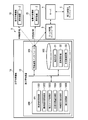
- FIG. 1 is a diagram showing an overall configuration of a construction management system according to the first embodiment.
- the construction management system 9 includes a plurality of work machines 1 that perform construction in the construction site F.
- the work machine 1 is a general work machine such as a power shovel, a bulldozer, or a wheel loader.
- One of the plurality of work machines 1 includes a construction management device 10.
- the working machine 1 provided with the construction management device 10 will be referred to as the lead working machine 1A, and the other working machines 1 will be referred to as the subordinate working machines 1B.
- the lead work machine 1A serves as a command tower and issues a construction instruction to the follower work machine 1B. Specifically, the lead work machine 1A notifies the follower work machine 1B of the goal of the construction of one day, that is, the intermediate design surface as the goal of the construction of the day. The operator who operates the conventional work machine 1B carries out construction for one day with the notified intermediate design surface as a target.
- the construction management device 10 generates an intermediate design surface for each work machine 1. Further, the construction management device 10 notifies each of the guided work machines 1B of the generated intermediate design surface. Specific processing of the construction management device 10 will be described later.
- the edge processing computer 3 is a computer installed in the site office of the construction site F or the like.
- the edge processing computer 3 collects various information from a drone (described later) and each work machine 1 capable of acquiring topographical information. Then, the edge processing computer 3 reduces the weight of various information collected (edge processing), and then transmits the information to the server device 4 through the wide area communication network G.
- the wide area communication network G is a so-called Internet communication network, a mobile communication network such as LTE/3G, or the like.
- the server device 4 sequentially updates and accumulates information received from the edge processing computer 3 (such as information indicating the current topography of the construction site F and the state of each work machine 1).
- the computer 5 of the construction company is a terminal device of the construction company and can access the server device 4 and the edge processing computer 3 through the wide area communication network G.
- FIG. 2 is a diagram showing a functional configuration of the construction management device and the like according to the first embodiment.
- the construction management device 10 has a CPU 100, a wireless communication interface 101, and a recording medium 102.
- the CPU 100 is a processor that controls the entire operation of the construction management device 10.
- the CPU 100 realizes each function described below by reading out a program or data stored in the recording medium 102 or the like onto a memory and executing a process defined by the program.
- the wireless communication interface 101 is a communication interface for the construction management device 10 to wirelessly transmit and receive information to and from the subsidiary work machine 1B existing in the construction site F.
- the wireless communication interface 101 may be, for example, a wireless LAN communication interface.
- the recording medium 102 is realized by a large-capacity recording device such as an HDD (Hard Disk Drive) and an SSD (Solid State Drive), and stores an OS (Operation System), application programs, and various data.
- the recording medium 102 records the current topography D1, the final design surface D2, and the work machine information D3.
- the current topography D1 is information indicating the current topography of the construction site F, and is composed of, for example, three-dimensional point cloud data.
- the current terrain D1 is acquired by flying a drone over the construction site F after the work of the day is completed. This drone is equipped with a stereo camera capable of photographing the ground from above the construction site F. While flying over the construction site F, the drone uses this stereo camera to take a bird's-eye view image. This bird's-eye view image is transferred to the edge processing computer 3 and is converted by the edge processing computer 3 into the current topographical data D1 as three-dimensional point cloud data.
- the edge processing computer 3 transmits the current terrain data D1 to the server device 4.
- the server device 4 records and updates the current terrain data D1.
- the construction management device 10 receives the current terrain data D1 from the server device 4 and records it in the recording medium 102 every day.
- the final design surface D2 is information indicating the final topography at the time of completion of construction at the construction site F.
- the final design surface D2 is composed of, for example, the same three-dimensional point cloud data as that of the current topography D1.
- the final design surface D2 is recorded in the server device 4 in advance.
- the construction management device 10 receives the final design surface D2 from the server device 4 and records it in the recording medium 102 in advance.
- the work machine information D3 is an information table that summarizes information about each work machine 1 to be constructed at the construction site F. The information included in the work machine information D3 will be described later.
- the work machine information D3 is also recorded in the server device 4 in advance.
- the construction management device 10 receives the work machine information D3 from the server device 4 and records it in the recording medium 102 in advance.
- the terminal device 2 is a terminal device mounted on each of the follower work machines 1B and realizes communication between an operator (site manager) of the lead work machine 1A and an operator of the follower work machine 1B.
- the terminal device 2 displays the intermediate design surface notified from the construction management device 10 on a display or the like and presents it to the operator of each of the guided work machines 1B.
- the CPU 100 operates in accordance with a predetermined program, so that the current terrain acquisition unit 1001, the final design surface acquisition unit 1002, the construction area acquisition unit 1003, the target work amount acquisition unit 1004, the intermediate design surface generation unit 1005, and the notification processing unit. It has the function of 1006.
- the current terrain acquisition unit 1001 acquires the current terrain (current terrain D1) at the construction site F with reference to the recording medium 102.
- the final design surface acquisition unit 1002 acquires the final design surface (final design surface D2) at the construction site F with reference to the recording medium 102.
- the construction area acquisition unit 1003 acquires the construction area of the work machine 1 at the construction site F.
- the “construction area” refers to an area of the construction site F that each work machine 1 is in charge of.
- the target work amount acquisition unit 1004 acquires the target work amount of the work machine 1 per unit time.
- the intermediate design surface generation unit 1005 acquires the current terrain acquired by the current terrain acquisition unit 1001, the final design surface acquired by the final design surface acquisition unit 1002, the construction area acquired by the construction area acquisition unit 1003, and the target work amount acquisition.
- An intermediate design surface for each work machine 1 is generated based on the target work amount per unit time acquired by the unit 1004.
- the notification processing unit 1006 transmits each intermediate design surface generated by the intermediate design surface generation unit 1005 to the terminal device 2 of each driven work machine 1B and notifies each operator.
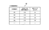
- FIG. 3 is a diagram showing an example of work machine information according to the first embodiment.
- the work machine information D3 recorded on the recording medium 102 will be described in detail with reference to FIG.
- the work machine information D3 includes a “work machine ID”, a “target work amount per day”, and a “construction area size” for each work machine 1 performing work at the construction site F.
- the “work machine ID” is an identifier that allows the work machine 1 working on the construction site F to be identified.
- the "target work amount per day” is information indicating a standard of the work amount (soil amount) that can be excavated by each work machine 1 per day, and is a value related to volume.
- the “target work amount per day” is individually determined based on the specifications (model, rated output, bucket capacity, etc.) of the work machine 1.
- Construction area size is information indicating the size of the range in which each work machine 1 can be constructed in the work per day, and is a value related to the area.
- the “construction area size” is also individually determined based on the specifications (model, rated output, bucket capacity, etc.) of the work machine 1 as with the “target work amount per day”.
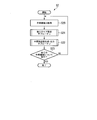
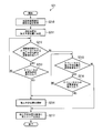
- FIGS. 4 to 10 are diagrams showing a processing flow of the construction management apparatus according to the first embodiment.
- 8 to 10 are diagrams used for detailed description of the process of the construction management device according to the first embodiment.
- the processing flow of the construction management device 10 according to the first embodiment will be described in detail with reference to FIGS. 4 to 10.
- the processing flow shown in FIG. 4 is executed based on the operation of an operator as a site manager who boards the initiative work machine 1A at the time of starting the work for one day.
- the current terrain acquisition unit 1001 of the construction management device 10 acquires the current terrain D1 recorded in the recording medium 102 (step S0).
- the present topography D1 indicates the topography of the construction site F at the end of the work yesterday.
- the current topography D1 is recorded in advance in the recording medium 102 by the construction management device 10 receiving it from the server device 4 every day.
- the final design surface acquisition unit 1002 of the construction management device 10 acquires the final design surface D2 recorded in the recording medium 102 (step S1). As described above, the final design surface D2 is recorded in the recording medium 102 in advance by the construction management device 10 receiving it from the server device 4 in advance.
- the construction management device 10 executes the intermediate design surface notification subroutine using the current topography D1 and the final design surface D2 acquired in steps S0 and S1 (step S2).
- the construction management device 10 makes a goal for construction on today for all the work machines 1 (including the lead work machine 1A in addition to the follower work machine 1B) working at the construction site F. And generate an intermediate design surface and notify each of them.
- step S2 The process of the intermediate design surface notification subroutine (step S2) will be described in detail below with reference to FIGS.
- the construction management device 10 acquires one of the work machine IDs recorded in the work machine information D3 (see FIG. 3) (step S20). As described above, the work machine information D3 is recorded in the recording medium 102 in advance by the construction management device 10 receiving it from the server device 4.
- the construction management device 10 executes the construction area setting subroutine (step S21) and the intermediate design surface generation/output subroutine (step S22) for the work machine 1 specified by the one work machine ID acquired in step S20. ..
- the construction management device 10 determines whether or not the construction area setting subroutine (step S21) and the intermediate design surface generation/output subroutine (step S22) have been executed for all the work machines 1 (step S23). When the construction area setting subroutine and the intermediate design surface generation/output subroutine are not executed for all the work machine IDs (step S23; NO), the construction management device 10 returns to step S20 to acquire another work machine ID.
- a construction area setting subroutine and an intermediate design surface generation/notification subroutine are executed for the work machine ID.
- the construction management device 10 completes the intermediate design surface notification subroutine (step S2).
- the construction area setting subroutine (step S21) will be described in detail with reference to FIG.
- the construction management device 10 executes the following process for the work machine 1 specified by the work machine ID acquired in step S20.
- one work machine 1 specified by the work machine ID acquired in step S20 will also be described as a “target work machine”.
- the construction area acquisition unit 1003 of the construction management device 10 acquires the current position of the target work machine (step S210).
- the work machine 1 according to the present embodiment is equipped with a GNSS (Global Navigation Satellite System) receiver and is capable of acquiring positioning information based on radio waves from satellites.
- the construction area acquisition unit 1003 can acquire the current position of the target work machine by receiving the positioning information from the target work machine.
- GNSS Global Navigation Satellite System
- the construction area acquisition unit 1003 determines the current position acquired in step S210 as the “scheduled construction position” of the target work machine (step S211).
- the “construction planned position” indicates a position (a position which is a reference of a construction area) which is a reference when the target work machine carries out the construction for one day today.
- the construction area acquisition unit 1003 provisionally determines the current position of the target work machine observed at the start of the work as the “scheduled construction position” of the target work machine.
- the site manager boarding the lead work machine 1A officially determines the planned construction position of each follow work machine 1B through dialogue with the operator of each follow work machine 1B. Specifically, it is as follows.
- the construction area acquisition unit 1003 receives an input of an instruction to change the planned construction position of the target work machine based on the operation of the site manager (step S212).
- the construction area acquisition unit 1003 transmits the change instruction to the terminal device 2 of the target work machine.
- the operator of the target work machine selects whether or not to accept this change instruction and inputs it to the terminal device 2.
- the construction area acquisition unit 1003 immediately receives the information input to the terminal device 2 (step S213).
- step S213 When the operator of the target work machine does not accept the change instruction (step S213; NO), the construction area acquisition unit 1003 returns to step S212.
- the construction area acquisition unit 1003 updates the planned construction position of the target work machine to the position specified by the change instruction in step S212 (step S212). S214). In this way, the construction area acquisition unit 1003 acquires the planned construction position of the target work machine based on the instruction from the site manager to the operator.
- the construction area acquisition unit 1003 determines whether the operator of the target work machine has received a request to change the planned construction position. The determination is made (step S215). In some cases, the operator of the target work machine may desire to change the scheduled construction position. In this case, the operator of the target work machine operates the terminal device 2 to send a request for changing the planned construction position to the site manager who is on board the lead work machine 1A. When receiving a request for changing the planned construction position from the operator of the target work machine (step S215; YES), the construction area acquiring unit 1003 notifies the site manager of the change request.
- the site manager selects whether or not to accept this change request and inputs it to the construction management device 10 (step S216).
- the construction area acquisition unit 1003 returns a message to that effect to the terminal device 2 of the target work machine, and returns to step S215.
- the construction area acquisition unit 1003 updates the planned construction position of the target work machine to the position designated by the change request in step S215 (step S214). ..
- the construction area acquisition unit 1003 updates the construction planned position (step S214). Proceed to the next process without performing. In this way, the construction area acquisition unit 1003 acquires the planned construction position of the target work machine based on the request (request for change) from the operator.
- the construction area acquisition unit 1003 determines a construction area based on the planned construction position determined based on each processing from step S210 to step S216 (step S217).
- step S217 A specific example of the process of step S217 will be described with reference to FIG.
- a point P shown in FIG. 8 is a planned work position determined for the target work machine through the processes from step S210 to step S216.
- the point P shown in FIG. 8 will be referred to as a scheduled work position P.
- the construction area acquisition unit 1003 defines a square centered on the scheduled work position P and having a side length of “L”.
- the construction area acquisition unit 1003 sets the area of the square having the length L of one side of the square as the value of “construction area size” recorded in the work machine information D3.
- the construction area acquisition unit 1003 determines the construction area AR of the target work machine based on the planned construction position P of the target work machine at the construction site F.
- the direction in which the square as the construction area AR is arranged can be appropriately determined from the azimuth angle based on the GNSS information of the target work machine.
- step S22 The intermediate design surface generation/output subroutine (step S22) will be described in detail with reference to FIG.
- the target work amount acquisition unit 1004 of the construction management device 10 refers to the work machine information D3 and acquires the target work amount per day of the target work machine (step S220).
- step S221 the intermediate design surface generation unit 1005 of the construction management device 10 calculates the construction target soil volume of the target work machine.
- Construction target soil volume refers to the total soil volume to be excavated in order to form the final design surface from the current topography within the area of the construction area AR assigned to the target work machine. The process of step S221 will be described in detail with reference to FIG.
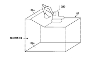
- FIG. 9 shows the target work machine 1N, the area current topography D1a, and the area final design surface D2a.
- the area current terrain D1a is terrain information of a region belonging to the construction area AR of the target work machine 1N among the current terrain D1 acquired in step S0 (FIG. 4).
- the area final design surface D2a is the terrain information of the area belonging to the construction area AR of the target work machine 1N among the final design surface D2 acquired in step S1 (FIG. 4).
- the intermediate design surface generation unit 1005 calculates the difference soil amount between the area current topography D1a and the area final design surface D2a as the construction target soil amount of the target work machine 1N.
- the intermediate design surface generation unit 1005 determines whether or not the construction target soil amount calculated in step S221 is equal to or less than the target work amount per day of the target work machine (step SS222). When the construction target soil amount is less than or equal to the target work amount per day of the target work machine (step S222; YES), the intermediate design surface generation unit 1005 sets the area final design surface D2a (FIG. 9) to the intermediate design surface. (Step S223).
- the intermediate design surface generation unit 1005 determines the area final design D1a (FIG. 9) to the area final design.
- a three-dimensional morphing process that smoothly (continuously) changes toward the surface D2a is performed to generate an intermediate design surface.
- the intermediate design surface generation unit 1005 increases the change rate by a predetermined minute value (for example, 1%) (step S224).
- the “rate of change” is a parameter indicating the degree of change in shape in the three-dimensional morphing process. For example, in the case of "change rate: 0%", the intermediate design surface becomes the area existing topography D1a itself, and in the case of "change rate: 100%", the intermediate design surface becomes the area final design surface D2a itself.
- the intermediate design surface generation unit 1005 calculates the difference soil volume between the intermediate design surface generated in step S224 and the area existing landform D1a. Then, it is determined whether or not the amount of soil difference between the intermediate design surface and the current area topography D1a matches the target work amount per day acquired in step S220 (step S225). When the difference soil amount between the intermediate design surface and the area current topography D1a does not match the daily target work amount acquired in step S220 (step S225; NO), the intermediate design surface generation unit 1005 returns to step S224, The rate of change is further increased by a very small value.
- the intermediate design surface generation unit 1005 increases the rate of change by repeating the processing of steps S224 to S225 until the difference soil amount between the intermediate design surface and the area current topography D1a matches the target work amount per day. Let The processing of steps S224 and S225 will be described in detail with reference to FIG.
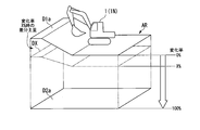
- FIG. 10 shows an intermediate design surface DX in addition to the target work machine 1N, the current area topography D1a, and the area final design surface D2a.
- the intermediate design surface DX is the terrain information generated by the three-dimensional morphing processing for changing the area existing terrain D1a to the area final design surface D2a.
- FIG. 10 shows the intermediate design surface DX at the time when the morphing process reaches a certain change rate X% (0 ⁇ X ⁇ 100). In this way, the intermediate design surface generation unit 1005 generates the intermediate design surface by morphing the existing terrain toward the final design surface.
- step S225 the intermediate design surface generation unit 1005 calculates the difference soil volume between the area current topography D1a and the intermediate design surface DX, as shown in FIG.
- the intermediate design surface generation unit 1005 repeats the processing of steps S224 to S225 to generate the intermediate design surface DX such that the difference soil amount matches the target work amount per day of the target work machine.
- the notification processing unit 1006 of the construction management device 10 transmits the generated intermediate design surface to the target work machine (step S226).
- this intermediate design surface is displayed on the terminal device 2 of the follower work machine 1B.
- this intermediate design surface is displayed on a monitor or the like mounted on the lead work machine 1A.
- the construction management device 10 includes the present-state terrain acquisition unit 1001 that acquires the present-terrain D1 at the construction site F and the final-design-surface acquisition unit that obtains the final design surface D2 at the construction site F. 1002, a construction area acquisition unit 1003 that acquires a construction area AR of the work machine 1 at the construction site F, a target work amount acquisition unit 1004 that acquires a target work amount per unit time (per day) of the work machine 1, An intermediate design surface generation unit 1005 that generates an intermediate design surface DX for the work machine 1 based on the current terrain D1, the final design surface D2, the construction area AR, and the target work amount per unit time, and the intermediate design.
- a notification processing unit 1006 that notifies the operator of the work machine 1 (the leading work machine 1A and the follower work machine 1B) of the surface DX. According to such a configuration, each work machine is notified of the intermediate design surface in which the characteristics peculiar to the work machine such as the construction area and the target work amount are taken into consideration. Therefore, the goal per unit time of each of the plurality of work machines can be appropriately set.
- the construction area acquisition unit 1003 determines a square section with one side length L based on the scheduled work position P as the construction area AR, but in another embodiment, this aspect. Not limited to.
- the construction area acquisition unit 1003 according to another embodiment may determine, as the construction area AR, a circular section having a diameter L based on the planned work position P. Further, the construction area AR may have any shape that does not belong to a rectangle or a circle. Further, the construction area acquisition unit 1003 according to another embodiment may determine a section having a different shape for each work machine 1 as the construction area AR of each work machine 1.
- the construction area acquisition unit 1003 may determine, as the construction area AR, a predetermined section or a section directly designated by the construction manager or the like regardless of the planned work position P. Good.
- the process for temporarily determining the planned construction position from the current position of the work machine (steps S210 and S211 shown in FIG. 6) is not essential.
- the target work amount per day of each work machine 1 has been described as being a value defined in advance in the work machine information D3, but other The embodiment is not limited to this aspect. For example, by comparing the current terrain D1 that is updated every day, it is possible to obtain the amount of soil actually excavated in the work in one day in the construction area AR that each work machine 1 is in charge of.
- the construction management device 10 may determine the target work amount per day of each work machine 1 based on the actual value of the amount of soil excavated in the work of the past day. Good. By doing so, it is possible to improve the accuracy of the target work amount per day recorded in the work machine information D3. Further, in another embodiment, the target work amount per day may be increased/decreased according to the skill of the operator (setting of “apprentice”, “experienced”, etc.).
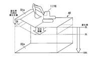
- FIG. 11 is a diagram used for detailed description of the process of the construction management device according to the modification of the first embodiment.
- the intermediate design surface generation unit 1005 of the construction management device 10 according to another embodiment may generate the intermediate design surface DX by translating the area final design surface D2a in the vertical direction.
- the direction of parallel translation is not limited to the vertical direction, but may be translated in any direction depending on the terrain shape.
- the construction management device 10 has been described as being installed in the work machine 1 (leading work machine 1A), and the operator of the leading work machine 1A has been described as a site manager.
- the construction management device 10 may be remotely located, such as a computer arranged in an office of a construction company or a server of a company that provides such construction management services.
- the site manager may be a person different from the operator of the work machine.
- various information to be referred to current terrain D1, final location).
- the design surface D2 and the work machine information D3) may be received from the server device 4 each time when necessary in the process of generating the intermediate design surface.
- FIG. 12 is a diagram used for a detailed description of a process (intermediate design surface generation/output subroutine) of the construction management device according to the modification of the first embodiment. For example, it is assumed that a unit time (for example, a target work amount per hour) that is not one day is recorded in the work machine information D3 according to the modification. In this case, as shown in FIG.
- the construction management device 10 first acquires the target work amount per unit time (per hour) of the target work machine 1N from the work machine information D3 (step S220a). Next, the construction management device 10 acquires a work time unit (for example, 8 hours) of the target work machine 1N on the current day (step S220b). Then, the construction management device 10 multiplies the target work amount per unit time acquired in step S220a by the work time unit acquired in step S220b to calculate the target work amount of the target work machine 1N for one day today ( Step S220c).
- the processes after step S221 in FIG. 12 are the same as those in the first embodiment, and thus the description thereof will be omitted.
- the construction management device 10 is also applicable to a case where a final design surface is formed from the existing topography by "filling", for example.
- the target work amount when the work machine performs "filling" is recorded as the target work amount per day.
- the processes of the various processes of the construction management apparatus 10 described above are stored in a computer-readable recording medium in the form of a program, and the various processes are performed by the computer reading and executing the program.
- the computer-readable recording medium means a magnetic disk, a magneto-optical disk, a CD-ROM, a DVD-ROM, a semiconductor memory, or the like.
- the computer program may be distributed to the computer via a communication line, and the computer that receives the distribution may execute the program.
- the above program may be for realizing a part of the above functions. Further, it may be a so-called difference file, a difference program, or the like that can realize the above-mentioned functions in combination with a program already recorded in the computer system.
Landscapes
- Business, Economics & Management (AREA)
- Human Resources & Organizations (AREA)
- Engineering & Computer Science (AREA)
- Economics (AREA)
- Strategic Management (AREA)
- Entrepreneurship & Innovation (AREA)
- Tourism & Hospitality (AREA)
- Physics & Mathematics (AREA)
- Theoretical Computer Science (AREA)
- Marketing (AREA)
- General Physics & Mathematics (AREA)
- General Business, Economics & Management (AREA)
- Quality & Reliability (AREA)
- Development Economics (AREA)
- Game Theory and Decision Science (AREA)
- Operations Research (AREA)
- Educational Administration (AREA)
- Life Sciences & Earth Sciences (AREA)
- Biodiversity & Conservation Biology (AREA)
- Health & Medical Sciences (AREA)
- General Health & Medical Sciences (AREA)
- Primary Health Care (AREA)
- Operation Control Of Excavators (AREA)
- Management, Administration, Business Operations System, And Electronic Commerce (AREA)
- Component Parts Of Construction Machinery (AREA)
- General Factory Administration (AREA)
Abstract
施工管理装置は、施工現場における現況地形を取得する現況地形取得部と、前記施工現場における最終設計面を取得する最終設計面取得部と、前記施工現場における作業機械の施工エリアを取得する施工エリア取得部と、前記作業機械の単位時間当たりの目標作業量を取得する目標作業量取得部と、前記最終設計面と、前記現況地形と、前記施工エリアと、前記単位時間当たりの目標作業量とに基づいて、前記作業機械についての中間設計面を生成する中間設計面生成部と、前記中間設計面を前記作業機械のオペレータに向けて通知する通知処理部と、を備える。
Description
本発明は、施工管理装置、施工管理システム、作業機械、施工管理方法及びプログラムに関する。
複数の作業機械がそれぞれの持ち場で作業を行う施工現場において、各作業機械の日々の目標施工量が明確でないために1日当たりの施工量の実績がばらついてしまい、予定通りに施工が進展しない事態が生じ得る。
そこで、現場管理者がその日ごとの施工の目標である中間設計面を作り、各作業機械に指示を出すことが検討されている。
特許文献1には、各作業機械それぞれに対し、本日行うべき作業内容をグラフィック表示させることが記載されている。
特許文献1には、各作業機械それぞれに対し、本日行うべき作業内容をグラフィック表示させることが記載されている。
上述の施工管理を行うに際し、作業機械の、単位時間(例えば1日)ごとのゴール(中間設計面)を適切に設定することが求められている。
本発明の目的は、複数の作業機械それぞれの、単位時間ごとの施工の目標を適切に設定することにある。
本発明の一態様によれば、施工管理装置は、施工現場における最終設計面を取得する最終設計面取得部と、前記施工現場における現況地形を取得する現況地形取得部と、前記施工現場における作業機械の施工エリアを取得する施工エリア取得部と、前記作業機械の単位時間当たりの目標作業量を取得する目標作業量取得部と、前記最終設計面と、前記現況地形と、前記施工エリアと、前記単位時間当たりの目標作業量とに基づいて、前記作業機械についての中間設計面を生成する中間設計面生成部と、前記中間設計面を前記作業機械のオペレータに向けて通知する通知処理部と、を備える。
上記態様によれば、複数の作業機械それぞれの、単位時間ごとの施工の目標を適切に設定することができる。
<第1の実施形態>
以下、第1の実施形態に係る施工管理システムについて、図1~図10を参照しながら詳細に説明する。
以下、第1の実施形態に係る施工管理システムについて、図1~図10を参照しながら詳細に説明する。
(施工管理システムの全体構成)
図1は、第1の実施形態に係る施工管理システムの全体構成を示す図である。
図1に示すように、施工管理システム9は、施工現場F内で施工を行う複数の作業機械1を有してなる。作業機械1は、パワーショベル、ブルドーザ、ホイールローダ等の一般的な作業機械である。
複数の作業機械1のうちの一つは、施工管理装置10を具備する。以下の説明において、施工管理装置10を具備する作業機械1を主導作業機械1Aとし、他の作業機械1を従導作業機械1Bとして区別する。
図1は、第1の実施形態に係る施工管理システムの全体構成を示す図である。
図1に示すように、施工管理システム9は、施工現場F内で施工を行う複数の作業機械1を有してなる。作業機械1は、パワーショベル、ブルドーザ、ホイールローダ等の一般的な作業機械である。
複数の作業機械1のうちの一つは、施工管理装置10を具備する。以下の説明において、施工管理装置10を具備する作業機械1を主導作業機械1Aとし、他の作業機械1を従導作業機械1Bとして区別する。
主導作業機械1Aは、司令塔となって、従導作業機械1Bに向けて施工の指示を出す。具体的には、主導作業機械1Aは、従導作業機械1Bに向けて、1日の施工の目標、すなわちその日の施工のゴールとしての中間設計面を通知する。従導作業機械1Bを操作するオペレータは、通知された中間設計面を目標として1日の施工を行う。
施工管理装置10は、作業機械1それぞれについての中間設計面を生成する。また、施工管理装置10は、生成した中間設計面を各従導作業機械1Bに向けて通知する。施工管理装置10の具体的な処理については後述する。
エッジ処理コンピュータ3は、施工現場Fの現場事務所内などに設置されるコンピュータである。エッジ処理コンピュータ3は、地形情報を取得可能なドローン(後述)や各作業機械1から、各種情報を収集する。そして、エッジ処理コンピュータ3は、収集した各種情報を軽量化(エッジ処理)した後、広域通信網Gを通じてサーバ装置4に送信する。なお、広域通信網Gは、いわゆるインターネット通信網、LTE/3G等のモバイル通信網などである。
サーバ装置4は、エッジ処理コンピュータ3から受信した情報(施工現場Fの現況地形や各作業機械1の状態を示す情報など)を逐次更新、蓄積する。
施工会社のコンピュータ5は、施工会社が有する端末装置であって、広域通信網Gを通じてサーバ装置4やエッジ処理コンピュータ3にアクセスすることができる。
サーバ装置4は、エッジ処理コンピュータ3から受信した情報(施工現場Fの現況地形や各作業機械1の状態を示す情報など)を逐次更新、蓄積する。
施工会社のコンピュータ5は、施工会社が有する端末装置であって、広域通信網Gを通じてサーバ装置4やエッジ処理コンピュータ3にアクセスすることができる。
(施工管理装置等の機能構成)
図2は、第1の実施形態に係る施工管理装置等の機能構成を示す図である。
図2に示すように、施工管理装置10は、CPU100と、無線通信インタフェース101と、記録媒体102とを有している。
図2は、第1の実施形態に係る施工管理装置等の機能構成を示す図である。
図2に示すように、施工管理装置10は、CPU100と、無線通信インタフェース101と、記録媒体102とを有している。
CPU100は、施工管理装置10の動作全体を司るプロセッサである。CPU100は、記録媒体102等に格納されたプログラムやデータをメモリ上に読み出し、当該プログラムに規定される処理を実行することで、後述の各機能を実現する。
無線通信インタフェース101は、施工管理装置10が無線を介して施工現場F内に存在する従導作業機械1Bと情報を送受信するための通信インタフェースである。無線通信インタフェース101は、例えば、無線LANの通信インタフェースであってよい。
記録媒体102は、例えば、HDD(Hard Disk Drive)、SSD(Solid State Drive)等の大容量記録デバイスにより実現され、OS(Operation System)、アプリケーションプログラム、及び、各種データ等を記憶する。本実施形態においては、記録媒体102には、現況地形D1、最終設計面D2、作業機械情報D3が記録されている。
現況地形D1は、現在の施工現場Fの地形を示す情報であって、例えば、三次元点群データからなる。現況地形D1は、1日の作業終了後に、施工現場Fの上空にドローンを飛行させることで取得される。このドローンは、施工現場Fの上空から地上を撮影可能なステレオカメラを具備している。ドローンは、施工現場Fの上空を飛行しながらこのステレオカメラを用いて俯瞰画像をくまなく撮影する。この俯瞰画像は、エッジ処理コンピュータ3に転送され、当該エッジ処理コンピュータ3で三次元点群データとしての現況地形データD1に変換される。エッジ処理コンピュータ3は、現況地形データD1をサーバ装置4に送信する。サーバ装置4は、現況地形データD1を記録、更新する。を三次元点群データに変換することで施工現場Fの現況地形D1が生成される。本実施形態においては、現況地形D1は、1日ごとに取得、更新される。
施工管理装置10は、1日ごとに、サーバ装置4から現況地形データD1を受信し、記録媒体102に記録しておく。
施工管理装置10は、1日ごとに、サーバ装置4から現況地形データD1を受信し、記録媒体102に記録しておく。
最終設計面D2は、施工現場Fの施工完了時における最終的な地形を示す情報である。最終設計面D2は、例えば、現況地形D1と同様の三次元点群データからなる。
最終設計面D2は、予めサーバ装置4に記録されている。施工管理装置10は、事前に、サーバ装置4から最終設計面D2を受信し、記録媒体102に記録しておく。
最終設計面D2は、予めサーバ装置4に記録されている。施工管理装置10は、事前に、サーバ装置4から最終設計面D2を受信し、記録媒体102に記録しておく。
作業機械情報D3は、施工現場Fで施工を行う作業機械1のそれぞれに関する情報をまとめた情報テーブルである。作業機械情報D3に含まれる情報については後述する。 作業機械情報D3も、予めサーバ装置4に記録されている。施工管理装置10は、事前に、サーバ装置4から作業機械情報D3を受信し、記録媒体102に記録しておく。
端末装置2は、各従導作業機械1Bに搭載される端末装置であって主導作業機械1Aのオペレータ(現場管理者)と従導作業機械1Bのオペレータとの間でのコミュニケーションを実現する。例えば、端末装置2は、施工管理装置10から通知された中間設計面をディスプレイなどに表示して各従導作業機械1Bのオペレータに提示する。
次に、本実施形態に係るCPU100が有する機能について詳しく説明する。
CPU100は、所定のプログラムに従って動作することで、現況地形取得部1001、最終設計面取得部1002、施工エリア取得部1003、目標作業量取得部1004、中間設計面生成部1005、及び、通知処理部1006としての機能を有する。
CPU100は、所定のプログラムに従って動作することで、現況地形取得部1001、最終設計面取得部1002、施工エリア取得部1003、目標作業量取得部1004、中間設計面生成部1005、及び、通知処理部1006としての機能を有する。
現況地形取得部1001は、記録媒体102を参照して、施工現場Fにおける現況地形(現況地形D1)を取得する。
最終設計面取得部1002は、記録媒体102を参照して、施工現場Fにおける最終設計面(最終設計面D2)を取得する。
施工エリア取得部1003は、施工現場Fにおける作業機械1の施工エリアを取得する。「施工エリア」とは、施工現場Fのうち各作業機械1が担当する領域のことを指す。 目標作業量取得部1004は、作業機械1の単位時間当たりの目標作業量を取得する。 中間設計面生成部1005は、現況地形取得部1001が取得した現況地形と、最終設計面取得部1002が取得した最終設計面と、施工エリア取得部1003が取得した施工エリアと、目標作業量取得部1004が取得した単位時間当たりの目標作業量とに基づいて、各作業機械1についての中間設計面を生成する。
通知処理部1006は、中間設計面生成部1005が生成した各中間設計面を、各従導作業機械1Bの端末装置2に向けて送信し、各オペレータに通知する。
最終設計面取得部1002は、記録媒体102を参照して、施工現場Fにおける最終設計面(最終設計面D2)を取得する。
施工エリア取得部1003は、施工現場Fにおける作業機械1の施工エリアを取得する。「施工エリア」とは、施工現場Fのうち各作業機械1が担当する領域のことを指す。 目標作業量取得部1004は、作業機械1の単位時間当たりの目標作業量を取得する。 中間設計面生成部1005は、現況地形取得部1001が取得した現況地形と、最終設計面取得部1002が取得した最終設計面と、施工エリア取得部1003が取得した施工エリアと、目標作業量取得部1004が取得した単位時間当たりの目標作業量とに基づいて、各作業機械1についての中間設計面を生成する。
通知処理部1006は、中間設計面生成部1005が生成した各中間設計面を、各従導作業機械1Bの端末装置2に向けて送信し、各オペレータに通知する。
(作業機械情報)
図3は、第1の実施形態に係る作業機械情報の例を示す図である。
記録媒体102に記録された作業機械情報D3について、図3を参照しながら詳しく説明する。
図3に示すように、作業機械情報D3は、施工現場Fで作業を行う各作業機械1についての「作業機械ID」と、「1日当たりの目標作業量」と、「施工エリア広さ」とを関連付けてなる情報テーブルである。
「作業機械ID」は、施工現場Fで作業を行う作業機械1を識別可能に付された識別子である。
「1日当たりの目標作業量」は、各作業機械1が1日当たりに掘削することができる作業量(土量)の目安を示す情報であり、体積に関する値である。「1日当たりの目標作業量」は、作業機械1のスペック(型式、定格出力、バケット容量など)に基づいて個別に定められる。
「施工エリア広さ」は、各作業機械1が1日当たりの作業において施工可能な範囲の広さを示す情報であり、面積に関する値である。「施工エリア広さ」も、「1日当たりの目標作業量」と同様に、作業機械1のスペック(型式、定格出力、バケット容量など)に基づいて個別に定められる。
図3は、第1の実施形態に係る作業機械情報の例を示す図である。
記録媒体102に記録された作業機械情報D3について、図3を参照しながら詳しく説明する。
図3に示すように、作業機械情報D3は、施工現場Fで作業を行う各作業機械1についての「作業機械ID」と、「1日当たりの目標作業量」と、「施工エリア広さ」とを関連付けてなる情報テーブルである。
「作業機械ID」は、施工現場Fで作業を行う作業機械1を識別可能に付された識別子である。
「1日当たりの目標作業量」は、各作業機械1が1日当たりに掘削することができる作業量(土量)の目安を示す情報であり、体積に関する値である。「1日当たりの目標作業量」は、作業機械1のスペック(型式、定格出力、バケット容量など)に基づいて個別に定められる。
「施工エリア広さ」は、各作業機械1が1日当たりの作業において施工可能な範囲の広さを示す情報であり、面積に関する値である。「施工エリア広さ」も、「1日当たりの目標作業量」と同様に、作業機械1のスペック(型式、定格出力、バケット容量など)に基づいて個別に定められる。
(施工管理装置の処理フロー)
図4~図7は、第1の実施形態に係る施工管理装置の処理フローを示す図である。
図8~図10は、第1の実施形態に係る施工管理装置の処理についての詳細な説明に用いる図である。
以下、図4~図10を参照しながら、第1の実施形態に係る施工管理装置10の処理の流れについて詳細に説明する。
図4~図7は、第1の実施形態に係る施工管理装置の処理フローを示す図である。
図8~図10は、第1の実施形態に係る施工管理装置の処理についての詳細な説明に用いる図である。
以下、図4~図10を参照しながら、第1の実施形態に係る施工管理装置10の処理の流れについて詳細に説明する。
図4に示す処理フローは、1日の作業を開始する時点で、主導作業機械1Aに搭乗する、現場管理者としてのオペレータの操作に基づいて実行される。
現場管理者から所定の操作を受け付けると、施工管理装置10の現況地形取得部1001は、記録媒体102に記録されている現況地形D1を取得する(ステップS0)。この現況地形D1は、昨日の作業終了時点での施工現場Fの地形形状を示すものである。
なお、上述したように、現況地形D1は、1日ごとに、施工管理装置10がサーバ装置4から受信することによって予め記録媒体102に記録されるものである。
なお、上述したように、現況地形D1は、1日ごとに、施工管理装置10がサーバ装置4から受信することによって予め記録媒体102に記録されるものである。
次に、施工管理装置10の最終設計面取得部1002は、記録媒体102に記録されている最終設計面D2を取得する(ステップS1)。
なお、上述したように、最終設計面D2は、事前に、施工管理装置10がサーバ装置4から受信することによって予め記録媒体102に記録されるものである。
なお、上述したように、最終設計面D2は、事前に、施工管理装置10がサーバ装置4から受信することによって予め記録媒体102に記録されるものである。
次に、施工管理装置10は、ステップS0、S1でそれぞれ取得した現況地形D1及び最終設計面D2を用いて、中間設計面通知サブルーチンを実行する(ステップS2)。この中間設計面通知サブルーチンでは、施工管理装置10は、施工現場Fで作業を行う全ての作業機械1(従導作業機械1Bに加え主導作業機械1Aを含む)について、今日1日の施工のゴールである中間設計面を生成してそれぞれに通知する。
以下、図5~図7を用いて中間設計面通知サブルーチン(ステップS2)の処理について詳しく説明する。
図5に示すように、施工管理装置10は、作業機械情報D3(図3参照)に記録されている作業機械IDのうち一つを取得する(ステップS20)。
なお、上述したように、作業機械情報D3は、事前に、施工管理装置10がサーバ装置4から受信することによって予め記録媒体102に記録されるものである。
なお、上述したように、作業機械情報D3は、事前に、施工管理装置10がサーバ装置4から受信することによって予め記録媒体102に記録されるものである。
施工管理装置10は、ステップS20で取得した一つの作業機械IDで特定される作業機械1について、施工エリア設定サブルーチン(ステップS21)と、中間設計面生成・出力サブルーチン(ステップS22)とを実行する。
施工管理装置10は、全ての作業機械1について、施工エリア設定サブルーチン(ステップS21)、及び、中間設計面生成・出力サブルーチン(ステップS22)を実行したか否かを判定する(ステップS23)。
全ての作業機械IDについて施工エリア設定サブルーチン及び中間設計面生成・出力サブルーチンが実行されていない場合(ステップS23;NO)、施工管理装置10は、ステップS20に戻って別の作業機械IDを取得し、当該作業機械IDについて、施工エリア設定サブルーチン、及び、中間設計面生成・通知サブルーチンを実行する。
全ての作業機械IDについて施工エリア設定サブルーチン及び中間設計面生成・通知サブルーチンが実行された場合(ステップS23;YES)、施工管理装置10は、中間設計面通知サブルーチン(ステップS2)を完了する。
施工管理装置10は、全ての作業機械1について、施工エリア設定サブルーチン(ステップS21)、及び、中間設計面生成・出力サブルーチン(ステップS22)を実行したか否かを判定する(ステップS23)。
全ての作業機械IDについて施工エリア設定サブルーチン及び中間設計面生成・出力サブルーチンが実行されていない場合(ステップS23;NO)、施工管理装置10は、ステップS20に戻って別の作業機械IDを取得し、当該作業機械IDについて、施工エリア設定サブルーチン、及び、中間設計面生成・通知サブルーチンを実行する。
全ての作業機械IDについて施工エリア設定サブルーチン及び中間設計面生成・通知サブルーチンが実行された場合(ステップS23;YES)、施工管理装置10は、中間設計面通知サブルーチン(ステップS2)を完了する。
図6を参照しながら、施工エリア設定サブルーチン(ステップS21)について詳しく説明する。
施工管理装置10は、ステップS20で取得した作業機械IDで特定される作業機械1について以下の処理を実行する。なお、以下の説明では、ステップS20で取得した作業機械IDによって特定される1台の作業機械1を「対象作業機械」とも表記して説明する。
施工管理装置10は、ステップS20で取得した作業機械IDで特定される作業機械1について以下の処理を実行する。なお、以下の説明では、ステップS20で取得した作業機械IDによって特定される1台の作業機械1を「対象作業機械」とも表記して説明する。
施工管理装置10の施工エリア取得部1003は、対象作業機械の現在位置を取得する(ステップS210)。ここで、本実施形態に係る作業機械1は、GNSS(Global Navigation Satellite System)受信機を搭載し、衛星からの電波に基づく測位情報を取得可能とされている。施工エリア取得部1003は、対象作業機械から測位情報を受信することで、対象作業機械の現在位置を取得することができる。
施工エリア取得部1003は、ステップS210で取得した現在位置を対象作業機械の「施工予定位置」に決定する(ステップS211)。「施工予定位置」とは、対象作業機械が、今日1日の施工を行うにあたっての基準となる位置(施工エリアの基準となる位置)を示す。ステップS211の処理により、施工エリア取得部1003は、作業開始時に観測された対象作業機械の現在位置を、当該対象作業機械の「施工予定位置」として仮決めする。
主導作業機械1Aに搭乗する現場管理者は、各従導作業機械1Bのオペレータとの対話を介して、各従導作業機械1Bの施工予定位置を正式に決定する。具体的には、以下のとおりである。
まず、現場管理者は、対象作業機械の施工予定位置を変更したい場合、施工管理装置10を操作して、当該対象作業機械のオペレータに向けて、施工予定位置の変更指示を送信する。この際、施工エリア取得部1003は、現場管理者の操作に基づき、対象作業機械についての施工予定位置の変更指示の入力を受け付ける(ステップS212)。
現場管理者から施工予定位置の変更指示の入力を受け付けた場合(ステップS212;YES)、施工エリア取得部1003は、当該変更指示を対象作業機械の端末装置2に送信する。対象作業機械のオペレータは、この変更指示を受け入れるか否かを選択し、端末装置2に入力する。施工エリア取得部1003は、端末装置2に入力された情報を直ちに受信する(ステップS213)。
対象作業機械のオペレータが変更指示を受け入れなかった場合(ステップS213;NO)、施工エリア取得部1003は、ステップS212に戻る。
対象作業機械のオペレータが変更指示を受け入れた場合(ステップS213;YES)、施工エリア取得部1003は、対象作業機械の施工予定位置を、ステップS212の変更指示で指定された位置に更新する(ステップS214)。
このように、施工エリア取得部1003は、対象作業機械の施工予定位置を、そのオペレータに対する現場管理者からの指示に基づいて取得する。
現場管理者から施工予定位置の変更指示の入力を受け付けた場合(ステップS212;YES)、施工エリア取得部1003は、当該変更指示を対象作業機械の端末装置2に送信する。対象作業機械のオペレータは、この変更指示を受け入れるか否かを選択し、端末装置2に入力する。施工エリア取得部1003は、端末装置2に入力された情報を直ちに受信する(ステップS213)。
対象作業機械のオペレータが変更指示を受け入れなかった場合(ステップS213;NO)、施工エリア取得部1003は、ステップS212に戻る。
対象作業機械のオペレータが変更指示を受け入れた場合(ステップS213;YES)、施工エリア取得部1003は、対象作業機械の施工予定位置を、ステップS212の変更指示で指定された位置に更新する(ステップS214)。
このように、施工エリア取得部1003は、対象作業機械の施工予定位置を、そのオペレータに対する現場管理者からの指示に基づいて取得する。
他方、現場管理者から施工予定位置の変更指示の入力がない場合(ステップS212;NO)、施工エリア取得部1003は、対象作業機械のオペレータから施工予定位置の変更希望を受信したか否かを判定する(ステップS215)。ここで、対象作業機械のオペレータ自身が施工予定位置の変更を希望する場合もある。この場合、対象作業機械のオペレータは、端末装置2を操作して、主導作業機械1Aに搭乗する現場管理者に向けて、施工予定位置の変更希望を送信する。
対象作業機械のオペレータから施工予定位置の変更希望を受信した場合(ステップS215;YES)、施工エリア取得部1003は、当該変更希望を現場管理者に通知する。現場管理者は、この変更希望を受け入れるか否かを選択し、施工管理装置10に入力する(ステップS216)。
現場管理者が変更希望を受け入れなかった場合(ステップS216;NO)、施工エリア取得部1003は、その旨を対象作業機械の端末装置2に返送し、ステップS215に戻る。
現場管理者が変更希望を受け入れた場合(ステップS216;YES)、施工エリア取得部1003は、対象作業機械の施工予定位置を、ステップS215の変更希望で指定された位置に更新する(ステップS214)。
現場管理者からの変更指示がなく(ステップS212;NO)、かつ、オペレータからの変更希望もなかった場合(ステップS215;NO)、施工エリア取得部1003は、施工予定位置の更新(ステップS214)をすることなく次の処理に進む。
このように、施工エリア取得部1003は、対象作業機械の施工予定位置を、そのオペレータからのリクエスト(変更希望)に基づいて取得する。
対象作業機械のオペレータから施工予定位置の変更希望を受信した場合(ステップS215;YES)、施工エリア取得部1003は、当該変更希望を現場管理者に通知する。現場管理者は、この変更希望を受け入れるか否かを選択し、施工管理装置10に入力する(ステップS216)。
現場管理者が変更希望を受け入れなかった場合(ステップS216;NO)、施工エリア取得部1003は、その旨を対象作業機械の端末装置2に返送し、ステップS215に戻る。
現場管理者が変更希望を受け入れた場合(ステップS216;YES)、施工エリア取得部1003は、対象作業機械の施工予定位置を、ステップS215の変更希望で指定された位置に更新する(ステップS214)。
現場管理者からの変更指示がなく(ステップS212;NO)、かつ、オペレータからの変更希望もなかった場合(ステップS215;NO)、施工エリア取得部1003は、施工予定位置の更新(ステップS214)をすることなく次の処理に進む。
このように、施工エリア取得部1003は、対象作業機械の施工予定位置を、そのオペレータからのリクエスト(変更希望)に基づいて取得する。
次に、施工エリア取得部1003は、ステップS210からステップS216までの各処理に基づいて決定された施工予定位置を基準にして、施工エリアを決定する(ステップS217)。このステップS217の処理の具体例について、図8を参照しながら説明する。
図8に示す点Pは、ステップS210からステップS216までの各処理を経て、対象作業機械について決定された作業予定位置である。以下、図8に示す点Pを、作業予定位置Pと表記する。施工エリア取得部1003は、この作業予定位置Pを中心とする、一辺の長さが“L”の正方形を規定する。このとき、施工エリア取得部1003は、正方形の一辺の長さLの正方形の面積を、作業機械情報D3に記録されている「施工エリア広さ」の値とする。
このように、施工エリア取得部1003は、施工現場Fにおける対象作業機械の施工予定位置Pに基づいて、当該対象作業機械の施工エリアARを決定する。
なお、施工現場Fにおいて、施工エリアARとしての正方形を配置する向きは、対象作業機械のGNSS情報に基づく方位角から適宜決定することができる。
このように、施工エリア取得部1003は、施工現場Fにおける対象作業機械の施工予定位置Pに基づいて、当該対象作業機械の施工エリアARを決定する。
なお、施工現場Fにおいて、施工エリアARとしての正方形を配置する向きは、対象作業機械のGNSS情報に基づく方位角から適宜決定することができる。
図7を参照しながら、中間設計面生成・出力サブルーチン(ステップS22)について詳しく説明する。
施工管理装置10の目標作業量取得部1004は、作業機械情報D3を参照して、対象作業機械の1日当たりの目標作業量を取得する(ステップS220)。
次に、施工管理装置10の中間設計面生成部1005は、対象作業機械の施工対象土量を演算する(ステップS221)。「施工対象土量」とは、対象作業機械に割り当てられた施工エリアARの領域内において、現況地形から最終設計面を形成するために掘削すべき全土量を示す。このステップS221の処理については、図9を参照しながら詳しく説明する。
図9には、対象作業機械1Nと、エリア現況地形D1aと、エリア最終設計面D2aとを示している。
エリア現況地形D1aは、ステップS0(図4)で取得した現況地形D1のうち対象作業機械1Nの施工エリアARに属する領域の地形情報である。
エリア最終設計面D2aは、ステップS1(図4)で取得した最終設計面D2のうち対象作業機械1Nの施工エリアARに属する領域の地形情報である。
エリア現況地形D1aは、ステップS0(図4)で取得した現況地形D1のうち対象作業機械1Nの施工エリアARに属する領域の地形情報である。
エリア最終設計面D2aは、ステップS1(図4)で取得した最終設計面D2のうち対象作業機械1Nの施工エリアARに属する領域の地形情報である。
図9に示すように、中間設計面生成部1005は、エリア現況地形D1aとエリア最終設計面D2aとの差分土量を、対象作業機械1Nの施工対象土量として演算する。
図7に戻り、次に、中間設計面生成部1005は、ステップS221で算出された施工対象土量が、対象作業機械の1日当たりの目標作業量以下か否かを判定する(ステップSS222)。
施工対象土量が、対象作業機械の1日当たりの目標作業量以下であった場合(ステップS222;YES)、中間設計面生成部1005は、エリア最終設計面D2a(図9)を、中間設計面として決定する(ステップS223)。
施工対象土量が、対象作業機械の1日当たりの目標作業量以下であった場合(ステップS222;YES)、中間設計面生成部1005は、エリア最終設計面D2a(図9)を、中間設計面として決定する(ステップS223)。
他方、施工対象土量が、対象作業機械の1日当たりの目標作業量よりも大きかった場合(ステップS222;NO)、中間設計面生成部1005は、エリア現況地形D1a(図9)からエリア最終設計面D2aに向けて滑らかに(連続的に)変化させる三次元モーフィング処理を行い、中間設計面を生成する。中間設計面生成部1005は、この三次元モーフィング処理において、変化率を所定の微小値(例えば1%)ずつ増加させる(ステップS224)。ここで、「変化率」とは、三次元モーフィング処理における形状の変化の度合いを示すパラメータである。例えば、「変化率:0%」の場合、中間設計面はエリア現況地形D1aそのものとなり、「変化率:100%」の場合、中間設計面はエリア最終設計面D2aそのものとなる。
次に、中間設計面生成部1005は、ステップS224で生成された中間設計面とエリア現況地形D1aとの差分土量を演算する。そして、中間設計面とエリア現況地形D1aとの差分土量が、ステップS220で取得した1日当たりの目標作業量に一致するか否かを判定する(ステップS225)。
中間設計面とエリア現況地形D1aとの差分土量が、ステップS220で取得した1日当たりの目標作業量に一致しない場合(ステップS225;NO)、中間設計面生成部1005は、ステップS224に戻り、変化率を更に微小値だけ増加させる。つまり、中間設計面生成部1005は、ステップS224~ステップS225の処理の繰り返しにより、中間設計面とエリア現況地形D1aとの差分土量が1日当たりの目標作業量に一致するまで、変化率を増加させる。ステップS224及びステップS225の処理については、図10を参照しながら詳しく説明する。
中間設計面とエリア現況地形D1aとの差分土量が、ステップS220で取得した1日当たりの目標作業量に一致しない場合(ステップS225;NO)、中間設計面生成部1005は、ステップS224に戻り、変化率を更に微小値だけ増加させる。つまり、中間設計面生成部1005は、ステップS224~ステップS225の処理の繰り返しにより、中間設計面とエリア現況地形D1aとの差分土量が1日当たりの目標作業量に一致するまで、変化率を増加させる。ステップS224及びステップS225の処理については、図10を参照しながら詳しく説明する。
図10には、対象作業機械1N、エリア現況地形D1a、エリア最終設計面D2aの他、更に、中間設計面DXを示している。
中間設計面DXは、エリア現況地形D1aからエリア最終設計面D2aへと変化させる三次元モーフィング処理によって生成される地形情報である。図10は、モーフィング処理がある変化率X%(0<X<100)まで進んだ時点での中間設計面DXを示している。このように、中間設計面生成部1005は、現況地形を最終設計面に向かってモーフィングすることによって中間設計面を生成する。
中間設計面DXは、エリア現況地形D1aからエリア最終設計面D2aへと変化させる三次元モーフィング処理によって生成される地形情報である。図10は、モーフィング処理がある変化率X%(0<X<100)まで進んだ時点での中間設計面DXを示している。このように、中間設計面生成部1005は、現況地形を最終設計面に向かってモーフィングすることによって中間設計面を生成する。
ステップS225において、中間設計面生成部1005は、図10に示すように、エリア現況地形D1aと中間設計面DXとの差分土量を演算する。中間設計面生成部1005は、ステップS224~ステップS225の処理を繰り返すことで、この差分土量が、対象作業機械の1日当たりの目標作業量と一致するような中間設計面DXを生成する。
図7に戻り、次に、施工管理装置10の通知処理部1006は、生成された中間設計面を対象作業機械に向けて送信する(ステップS226)。対象作業機械が従導作業機械1Bである場合には、この中間設計面は、従導作業機械1Bの端末装置2で表示される。対象作業機械が主導作業機械1Aである場合には、この中間設計面は、主導作業機械1Aに搭載されるモニタ等に表示される。これにより、対象作業機械のオペレータは、今日1日の施工のゴールである中間設計面を認識できる。
(作用、効果)
以上の通り、第1の実施形態に係る施工管理装置10は、施工現場Fにおける現況地形D1を取得する現況地形取得部1001と、施工現場Fにおける最終設計面D2を取得する最終設計面取得部1002と、施工現場Fにおける作業機械1の施工エリアARを取得する施工エリア取得部1003と、作業機械1の単位時間当たり(1日当たり)の目標作業量を取得する目標作業量取得部1004と、現況地形D1と、最終設計面D2と、施工エリアARと、単位時間当たりの目標作業量とに基づいて、作業機械1についての中間設計面DXを生成する中間設計面生成部1005と、中間設計面DXを作業機械1(主導作業機械1A及び従導作業機械1B)のオペレータに向けて通知する通知処理部1006と、を備える。
このような構成によれば、施工エリア、目標作業量などの作業機械固有の特性が考慮された中間設計面が各作業機械に通知される。したがって、複数の作業機械それぞれの、単位時間ごとのゴールを適切に設定することができる。
以上の通り、第1の実施形態に係る施工管理装置10は、施工現場Fにおける現況地形D1を取得する現況地形取得部1001と、施工現場Fにおける最終設計面D2を取得する最終設計面取得部1002と、施工現場Fにおける作業機械1の施工エリアARを取得する施工エリア取得部1003と、作業機械1の単位時間当たり(1日当たり)の目標作業量を取得する目標作業量取得部1004と、現況地形D1と、最終設計面D2と、施工エリアARと、単位時間当たりの目標作業量とに基づいて、作業機械1についての中間設計面DXを生成する中間設計面生成部1005と、中間設計面DXを作業機械1(主導作業機械1A及び従導作業機械1B)のオペレータに向けて通知する通知処理部1006と、を備える。
このような構成によれば、施工エリア、目標作業量などの作業機械固有の特性が考慮された中間設計面が各作業機械に通知される。したがって、複数の作業機械それぞれの、単位時間ごとのゴールを適切に設定することができる。
(変形例)
以上、第1の実施形態に係る施工管理装置10について詳しく説明したが、施工管理装置10の具体的な態様は、上述のものに限定されることはなく、要旨を逸脱しない範囲内において種々の設計変更等を加えることは可能である。
以上、第1の実施形態に係る施工管理装置10について詳しく説明したが、施工管理装置10の具体的な態様は、上述のものに限定されることはなく、要旨を逸脱しない範囲内において種々の設計変更等を加えることは可能である。
例えば、第1の実施形態に係る施工エリア取得部1003は、作業予定位置Pを基準とする一辺の長さLの正方形の区画を施工エリアARとして決定したが、他の実施形態においてはこの態様に限定されない。他の実施形態に係る施工エリア取得部1003は、作業予定位置Pを基準とする直径Lの円形状の区画を施工エリアARとして決定してもよい。また、施工エリアARは、矩形、円形に属さない任意の形状であってよい。また、他の実施形態に係る施工エリア取得部1003は、作業機械1ごとに異なる形状の区画を、各作業機械1の施工エリアARとして決定してもよい。
また、他の実施形態に係る施工エリア取得部1003は、作業予定位置Pにかかわらず、予め定められた区画、又は、施工管理者等によって直接指定された区画を施工エリアARとして決定してもよい。この場合、作業機械の現在位置から施工予定位置を仮決めするための処理(図6に示すステップS210およびステップS211)は、必須ではない。
また、他の実施形態に係る施工エリア取得部1003は、作業予定位置Pにかかわらず、予め定められた区画、又は、施工管理者等によって直接指定された区画を施工エリアARとして決定してもよい。この場合、作業機械の現在位置から施工予定位置を仮決めするための処理(図6に示すステップS210およびステップS211)は、必須ではない。
また、第1の実施形態に係る施工管理装置10では、各作業機械1の1日当たりの目標作業量は、作業機械情報D3で事前に規定されている値であるものとして説明したが、他の実施形態においてはこの態様に限定されない。
例えば、1日ごとに更新される現況地形D1を比較すれば、各作業機械1がそれぞれ担当する施工エリアARにおいて、1日の作業で実際に掘削された土量を取得することができる。他の実施形態に係る施工管理装置10は、各作業機械1の1日当たりの目標作業量を、過去の1日の作業で掘削された土量の実績値に基づいて決定するものであってもよい。このようにすることで、作業機械情報D3に記録される1日当たりの目標作業量の精度を高めることができる。また、他の実施形態においては、更に、1日当たりの目標作業量がオペレータの技能(「見習い」、「ベテラン」等の設定)に応じて増減調整されるものであってもよい。
例えば、1日ごとに更新される現況地形D1を比較すれば、各作業機械1がそれぞれ担当する施工エリアARにおいて、1日の作業で実際に掘削された土量を取得することができる。他の実施形態に係る施工管理装置10は、各作業機械1の1日当たりの目標作業量を、過去の1日の作業で掘削された土量の実績値に基づいて決定するものであってもよい。このようにすることで、作業機械情報D3に記録される1日当たりの目標作業量の精度を高めることができる。また、他の実施形態においては、更に、1日当たりの目標作業量がオペレータの技能(「見習い」、「ベテラン」等の設定)に応じて増減調整されるものであってもよい。
第1の実施形態に係る施工管理装置10は、モーフィング処理を用いて、施工エリアAR内において三次元現況地形から最終設計面へと滑らかに変化させることを説明したが他の実施形態においてはこの態様に限定されない。
図11は、第1の実施形態の変形例に係る施工管理装置の処理についての詳細な説明に用いる図である。
図11に示すように、他の実施形態に係る施工管理装置10の中間設計面生成部1005は、エリア現況地形D1aを鉛直方向に平行移動させて中間設計面DXを生成するものであってもよい。
また、他の実施形態に係る施工管理装置10の中間設計面生成部1005は、エリア最終設計面D2aを鉛直方向に平行移動させて中間設計面DXを生成するものであってもよい。
また、上述の変形例において平行移動させる方向は鉛直方向のみに限られず、地形形状に応じて、任意の方向に平行移動させてもよい。
図11は、第1の実施形態の変形例に係る施工管理装置の処理についての詳細な説明に用いる図である。
図11に示すように、他の実施形態に係る施工管理装置10の中間設計面生成部1005は、エリア現況地形D1aを鉛直方向に平行移動させて中間設計面DXを生成するものであってもよい。
また、他の実施形態に係る施工管理装置10の中間設計面生成部1005は、エリア最終設計面D2aを鉛直方向に平行移動させて中間設計面DXを生成するものであってもよい。
また、上述の変形例において平行移動させる方向は鉛直方向のみに限られず、地形形状に応じて、任意の方向に平行移動させてもよい。
また、第1の実施形態に係る施工管理装置10は、作業機械1(主導作業機械1A)に搭載されるものとして説明し、主導作業機械1Aのオペレータが現場管理者を務めるものとして説明したが、他の実施形態においてはこの態様に限定されない。例えば、施工管理装置10は、施工会社の事務所に配置されるコンピュータや、このような施工管理のサービスを提供する会社のサーバなど、遠隔地に配置されるものであっても良い。また、現場管理者は作業機械のオペレータとは別の人員であってもよい
更に、施工管理装置10が作業機械1に搭載される態様であっても、参照する各種情報(現況地形D1、最終設計面D2、及び、作業機械情報D3)は、中間設計面を生成する過程で必要な場合に、その都度、サーバ装置4から受信する態様であってもよい。
更に、施工管理装置10が作業機械1に搭載される態様であっても、参照する各種情報(現況地形D1、最終設計面D2、及び、作業機械情報D3)は、中間設計面を生成する過程で必要な場合に、その都度、サーバ装置4から受信する態様であってもよい。
また、第1の実施形態に係る施工管理装置10は、中間設計面生成・出力サブルーチン(図5のステップS22)において、1日当たりの目標作業量を、作業機械情報D3から直接取得するものとして説明した(図7のステップS220)。しかし、他の実施形態においてはこの態様に限られない。
図12は、第1の実施形態の変形例に係る施工管理装置の処理(中間設計面生成・出力サブルーチン)についての詳細な説明に用いる図である。
例えば、変形例に係る作業機械情報D3には、1日ではない単位時間(例えば、1時間当たりの目標作業量)が記録されていたとする。この場合は、図12に示すように、施工管理装置10は、まず、作業機械情報D3から、対象作業機械1Nの単位時間当たり(1時間当たり)の目標作業量を取得する(ステップS220a)。次に、施工管理装置10は、対象作業機械1Nの今日1日の作業時間単位(例えば、8時間)を取得する(ステップS220b)。そして、施工管理装置10は、ステップS220aで取得した単位時間当たりの目標作業量に、ステップS220bで取得した作業時間単位を乗じて、対象作業機械1Nの今日1日の目標作業量を演算する(ステップS220c)。
図12のステップS221以降の処理については、第1の実施形態と同様であるため、説明を省略する。
図12は、第1の実施形態の変形例に係る施工管理装置の処理(中間設計面生成・出力サブルーチン)についての詳細な説明に用いる図である。
例えば、変形例に係る作業機械情報D3には、1日ではない単位時間(例えば、1時間当たりの目標作業量)が記録されていたとする。この場合は、図12に示すように、施工管理装置10は、まず、作業機械情報D3から、対象作業機械1Nの単位時間当たり(1時間当たり)の目標作業量を取得する(ステップS220a)。次に、施工管理装置10は、対象作業機械1Nの今日1日の作業時間単位(例えば、8時間)を取得する(ステップS220b)。そして、施工管理装置10は、ステップS220aで取得した単位時間当たりの目標作業量に、ステップS220bで取得した作業時間単位を乗じて、対象作業機械1Nの今日1日の目標作業量を演算する(ステップS220c)。
図12のステップS221以降の処理については、第1の実施形態と同様であるため、説明を省略する。
また、第1の実施形態においては、“掘削”により現況地形から最終設計面を形成する場合を例に説明したが、他の実施形態においてはこれに限定されない。他の実施形態に係る施工管理装置10は、例えば、“盛り土”により現況地形から最終設計面を形成する場合にも適用可能である。この場合、作業機械情報D3には、1日当たりの目標作業量として、作業機械が“盛り土”を行う際の目標作業量が記録される。
なお、上述した施工管理装置10の各種処理の過程は、プログラムの形式でコンピュータ読み取り可能な記録媒体に記憶されており、このプログラムをコンピュータが読み出して実行することによって上記各種処理が行われる。また、コンピュータ読み取り可能な記録媒体とは、磁気ディスク、光磁気ディスク、CD-ROM、DVD-ROM、半導体メモリ等をいう。また、このコンピュータプログラムを通信回線によってコンピュータに配信し、この配信を受けたコンピュータが当該プログラムを実行するようにしてもよい。
上記プログラムは、上述した機能の一部を実現するためのものであってもよい。更に、上述した機能をコンピュータシステムにすでに記録されているプログラムとの組み合わせで実現できるもの、いわゆる差分ファイル、又は差分プログラム等であってもよい。
以上、本発明のいくつかの実施形態を説明したが、これらの実施形態は、例として提示したものであり、発明の範囲を限定することは意図していない。これら実施形態は、その他の様々な形態で実施されることが可能であり、発明の要旨を逸脱しない範囲で種々の省略、置き換え、変更を行うことができる。これら実施形態やその変形は、発明の範囲や要旨に含まれると同様に、特許請求の範囲に記載された発明とその均等の範囲に含まれる。
本発明によれば、複数の作業機械それぞれの、単位時間ごとの施工の目標を適切に設定することができる。
1 作業機械、10 施工管理装置、100 CPU、1001 現況地形取得部、1002 最終設計面取得部、1003 施工エリア取得部、1004 目標作業量取得部、1005 中間設計面生成部、1006 通知処理部、101 無線通信インタフェース、102 記録媒体、2 端末装置、3 エッジ処理コンピュータ、4 サーバ装置、5 施工会社のコンピュータ、9 施工管理システム
Claims (11)
- 施工現場における現況地形を取得する現況地形取得部と、
前記施工現場における最終設計面を取得する最終設計面取得部と、
前記施工現場における作業機械の施工エリアを取得する施工エリア取得部と、
前記作業機械の単位時間当たりの目標作業量を取得する目標作業量取得部と、
前記最終設計面と、前記現況地形と、前記施工エリアと、前記単位時間当たりの目標作業量とに基づいて、前記作業機械についての中間設計面を生成する中間設計面生成部と、
前記中間設計面を前記作業機械のオペレータに向けて通知する通知処理部と、
を備える施工管理装置。 - 前記中間設計面生成部は、
前記施工エリアにおける前記現況地形と前記中間設計面との差分土量が前記単位時間当たりの目標作業量と一致するように、当該中間設計面を生成する
請求項1に記載の施工管理装置。 - 前記施工エリア取得部は、
前記施工現場における前記作業機械の施工予定位置に基づいて前記施工エリアを決定する
請求項1又は請求項2に記載の施工管理装置。 - 前記施工エリア取得部は、
前記施工予定位置を、前記オペレータからのリクエストに基づいて取得する
請求項3に記載の施工管理装置。 - 前記施工エリア取得部は、
前記施工予定位置を、前記オペレータに対する現場管理者からの指示に基づいて取得する
請求項3又は請求項4に記載の施工管理装置。 - 前記中間設計面生成部は、
前記現況地形を前記最終設計面に向かってモーフィングすることによって前記中間設計面を生成する
請求項1から請求項5のいずれか一項に記載の施工管理装置。 - 前記目標作業量取得部は、
前記作業機械の過去の実績に基づいて、前記単位時間当たりの目標作業量を決定する 請求項1から請求項6のいずれか一項に記載の施工管理装置。 - 請求項1から請求項7のいずれか一項に記載の施工管理装置と、
前記施工管理装置から受信した前記中間設計面を表示する端末装置と、
を備える施工管理システム。 - 請求項1から請求項7のいずれか一項に記載の施工管理装置を備える
作業機械。 - 施工現場における現況地形を取得するステップと、
前記施工現場における最終設計面を取得するステップと、
前記施工現場における作業機械の施工エリアを取得するステップと、
前記作業機械の単位時間当たりの目標作業量を取得するステップと、
前記最終設計面と、前記現況地形と、前記施工エリアと、前記単位時間当たりの目標作業量とに基づいて、前記作業機械についての中間設計面を生成するステップと、
前記中間設計面を、前記作業機械を用いて施工を行うオペレータに向けて通知するステップと、
を有する施工管理方法。 - 施工管理装置のコンピュータに、
施工現場における現況地形を取得するステップと、
前記施工現場における最終設計面を取得するステップと、
前記施工現場における作業機械の施工エリアを取得するステップと、
前記作業機械の単位時間当たりの目標作業量を取得するステップと、
前記最終設計面と、前記現況地形と、前記施工エリアと、前記単位時間当たりの目標作業量とに基づいて、前記作業機械についての中間設計面を生成するステップと、
前記中間設計面を、前記作業機械を用いて施工を行うオペレータに向けて通知するステップと、
を実行させるプログラム。
Priority Applications (5)
| Application Number | Priority Date | Filing Date | Title |
|---|---|---|---|
| DE112019006693.5T DE112019006693T5 (de) | 2019-02-26 | 2019-11-18 | Arbeitsverwaltungsvorrichtung, Arbeitsverwaltungssystem, Arbeitsmaschine, Arbeitsverwaltungsverfahren und Programm |
| AU2019431055A AU2019431055A1 (en) | 2019-02-26 | 2019-11-18 | Work management device, work management system, operation machine, work management method, and program |
| CN201980092573.2A CN113474806A (zh) | 2019-02-26 | 2019-11-18 | 施工管理装置、施工管理系统、作业机械、施工管理方法及程序 |
| US17/429,364 US20220108243A1 (en) | 2019-02-26 | 2019-11-18 | Work management device, work management system, operation machine, work management method, and program |
| AU2023222971A AU2023222971A1 (en) | 2019-02-26 | 2023-08-31 | Work management device, work management system, operation machine, work management method, and program |
Applications Claiming Priority (2)
| Application Number | Priority Date | Filing Date | Title |
|---|---|---|---|
| JP2019-033036 | 2019-02-26 | ||
| JP2019033036A JP7165599B2 (ja) | 2019-02-26 | 2019-02-26 | 施工管理装置、施工管理システム、作業機械、施工管理方法及びプログラム |
Publications (1)
| Publication Number | Publication Date |
|---|---|
| WO2020174774A1 true WO2020174774A1 (ja) | 2020-09-03 |
Family
ID=72238915
Family Applications (1)
| Application Number | Title | Priority Date | Filing Date |
|---|---|---|---|
| PCT/JP2019/045017 Ceased WO2020174774A1 (ja) | 2019-02-26 | 2019-11-18 | 施工管理装置、施工管理システム、作業機械、施工管理方法及びプログラム |
Country Status (6)
| Country | Link |
|---|---|
| US (1) | US20220108243A1 (ja) |
| JP (1) | JP7165599B2 (ja) |
| CN (1) | CN113474806A (ja) |
| AU (2) | AU2019431055A1 (ja) |
| DE (1) | DE112019006693T5 (ja) |
| WO (1) | WO2020174774A1 (ja) |
Cited By (1)
| Publication number | Priority date | Publication date | Assignee | Title |
|---|---|---|---|---|
| US12639773B2 (en) | 2021-03-31 | 2026-05-26 | Komatsu Ltd. | Construction management system, data processing device, and construction management method |
Families Citing this family (1)
| Publication number | Priority date | Publication date | Assignee | Title |
|---|---|---|---|---|
| JP7715513B2 (ja) * | 2021-03-25 | 2025-07-30 | 株式会社奥村組 | 運土計画管理装置、運土計画管理方法および運土計画管理プログラム |
Citations (3)
| Publication number | Priority date | Publication date | Assignee | Title |
|---|---|---|---|---|
| JP2007177541A (ja) * | 2005-12-28 | 2007-07-12 | Mitsubishi Heavy Ind Ltd | 構造物現地据付システム |
| WO2017061517A1 (ja) * | 2015-10-05 | 2017-04-13 | 株式会社小松製作所 | 施工管理システム及び施工管理方法 |
| WO2017170968A1 (ja) * | 2016-03-30 | 2017-10-05 | 株式会社小松製作所 | シミュレーションシステム及びシミュレーション方法 |
Family Cites Families (14)
| Publication number | Priority date | Publication date | Assignee | Title |
|---|---|---|---|---|
| CA2535740A1 (en) * | 2003-09-12 | 2005-04-21 | Carlson Software, Inc. | Fluvial geomorphic landscape design computer software |
| US8620535B2 (en) * | 2012-05-21 | 2013-12-31 | Caterpillar Inc. | System for automated excavation planning and control |
| US9260837B1 (en) * | 2014-09-10 | 2016-02-16 | Caterpillar Inc. | Intelligent pass jump control |
| US9904747B2 (en) * | 2015-03-19 | 2018-02-27 | Trimble Inc. | Agricultural terrain forming based on soil modeling |
| JP6496182B2 (ja) * | 2015-04-28 | 2019-04-03 | 株式会社小松製作所 | 施工計画システム |
| US10186004B2 (en) * | 2015-05-20 | 2019-01-22 | Caterpillar Inc. | System and method for evaluating a material movement plan |
| AU2016283735A1 (en) * | 2015-06-23 | 2017-12-21 | Komatsu Ltd. | Construction management system and construction management method |
| US9481977B1 (en) * | 2015-07-24 | 2016-11-01 | Caterpillar Inc. | System and method for controlling a machine |
| KR20170113604A (ko) * | 2015-09-30 | 2017-10-12 | 가부시키가이샤 고마쓰 세이사쿠쇼 | 화상 데이터 생성 방법 |
| AU2015261600A1 (en) * | 2015-11-25 | 2017-06-08 | Caterpillar Of Australia Pty Ltd | Graphical user interface for designing terrain modification plans |
| US10775796B2 (en) * | 2017-01-10 | 2020-09-15 | Cnh Industrial America Llc | Aerial vehicle systems and methods |
| US11761173B2 (en) * | 2018-06-26 | 2023-09-19 | Caterpillar Inc. | Systems and methods for building a pad |
| US10794039B2 (en) * | 2018-08-08 | 2020-10-06 | Caterpillar Inc. | System and method for controlling the operation of a machine |
| US10774506B2 (en) * | 2018-09-28 | 2020-09-15 | Caterpillar Inc. | System and method for controlling the operation of a machine |
-
2019
- 2019-02-26 JP JP2019033036A patent/JP7165599B2/ja active Active
- 2019-11-18 DE DE112019006693.5T patent/DE112019006693T5/de active Pending
- 2019-11-18 AU AU2019431055A patent/AU2019431055A1/en not_active Abandoned
- 2019-11-18 CN CN201980092573.2A patent/CN113474806A/zh active Pending
- 2019-11-18 WO PCT/JP2019/045017 patent/WO2020174774A1/ja not_active Ceased
- 2019-11-18 US US17/429,364 patent/US20220108243A1/en not_active Abandoned
-
2023
- 2023-08-31 AU AU2023222971A patent/AU2023222971A1/en not_active Abandoned
Patent Citations (3)
| Publication number | Priority date | Publication date | Assignee | Title |
|---|---|---|---|---|
| JP2007177541A (ja) * | 2005-12-28 | 2007-07-12 | Mitsubishi Heavy Ind Ltd | 構造物現地据付システム |
| WO2017061517A1 (ja) * | 2015-10-05 | 2017-04-13 | 株式会社小松製作所 | 施工管理システム及び施工管理方法 |
| WO2017170968A1 (ja) * | 2016-03-30 | 2017-10-05 | 株式会社小松製作所 | シミュレーションシステム及びシミュレーション方法 |
Cited By (1)
| Publication number | Priority date | Publication date | Assignee | Title |
|---|---|---|---|---|
| US12639773B2 (en) | 2021-03-31 | 2026-05-26 | Komatsu Ltd. | Construction management system, data processing device, and construction management method |
Also Published As
| Publication number | Publication date |
|---|---|
| JP7165599B2 (ja) | 2022-11-04 |
| US20220108243A1 (en) | 2022-04-07 |
| AU2023222971A1 (en) | 2023-09-21 |
| AU2019431055A1 (en) | 2021-09-02 |
| DE112019006693T5 (de) | 2021-09-30 |
| CN113474806A (zh) | 2021-10-01 |
| JP2020140233A (ja) | 2020-09-03 |
Similar Documents
| Publication | Publication Date | Title |
|---|---|---|
| US11143762B2 (en) | GNSS correction data distribution device, GNSS correction data distribution system, and GNSS correction data distribution method | |
| KR101548647B1 (ko) | 3차원 지형정보 가시화 프로세서 및 그 동작방법 | |
| CN105556408B (zh) | 一种飞行器的飞行控制方法及相关装置 | |
| AU2023222971A1 (en) | Work management device, work management system, operation machine, work management method, and program | |
| AU2026202304A1 (en) | Image-based productivity tracking system | |
| EP3186685A1 (en) | Three-dimensional elevation modeling for use in operating agricultural vehicles | |
| EP3885871A1 (en) | Surveying and mapping system, surveying and mapping method and apparatus, device and medium | |
| WO2019012988A1 (ja) | 地形情報送信装置、施工管理システム及び地形情報送信方法 | |
| CN117724467A (zh) | 一种路径规划方法、相关装置及系统 | |
| CN115412926B (zh) | 基站站址规划方法、基站站址规划系统、设备及介质 | |
| CN112801409B (zh) | 一种基于bim的工程监理信息管理方法、系统、以及存储介质 | |
| EP3885940A1 (en) | Job control system, job control method, apparatus, device and medium | |
| CN112509137B (zh) | 基于三维模型的桥梁施工进度监控方法、系统和存储介质 | |
| KR20230007256A (ko) | 도로 데이터 융합의 지도 생성 방법, 장치 및 전자 기기 | |
| JP7248122B2 (ja) | 掘削軌道生成方法、システム、及び掘削軌道生成装置 | |
| CN110644563A (zh) | 用于构建衬垫的系统和方法 | |
| CN112836991B (zh) | 站点规划方法、装置、终端设备和可读存储介质 | |
| WO2025020329A1 (zh) | 一种路侧设备的感知方法、系统、设备及存储介质 | |
| CN110058260B (zh) | 用于定向lidar系统的地图的方法 | |
| CN115082396A (zh) | 光伏电站基建进度的智能勘测方法、系统及介质 | |
| CN119594958A (zh) | 三维地图采集更新方法、装置及电子设备 | |
| CN112753002B (zh) | 航点规划方法、控制终端、定位装置、系统及存储介质 | |
| CN115265504B (zh) | 一种三维地形测绘方法、系统及终端设备 | |
| JP2012085139A (ja) | 離隔距離の計算装置としてコンピュータを機能させるためのプログラム | |
| CN116843824A (zh) | 三维模型实时重建方法、装置及系统 |
Legal Events
| Date | Code | Title | Description |
|---|---|---|---|
| 121 | Ep: the epo has been informed by wipo that ep was designated in this application |
Ref document number: 19917153 Country of ref document: EP Kind code of ref document: A1 |
|
| ENP | Entry into the national phase |
Ref document number: 2019431055 Country of ref document: AU Date of ref document: 20191118 Kind code of ref document: A |
|
| 122 | Ep: pct application non-entry in european phase |
Ref document number: 19917153 Country of ref document: EP Kind code of ref document: A1 |