WO2020171047A1 - カーボンナノチューブの製造方法、カーボンナノチューブ集合線の製造方法、カーボンナノチューブ集合線バンドルの製造方法、カーボンナノチューブ製造装置、カーボンナノチューブ集合線製造装置及びカーボンナノチューブ集合線バンドル製造装置 - Google Patents
カーボンナノチューブの製造方法、カーボンナノチューブ集合線の製造方法、カーボンナノチューブ集合線バンドルの製造方法、カーボンナノチューブ製造装置、カーボンナノチューブ集合線製造装置及びカーボンナノチューブ集合線バンドル製造装置 Download PDFInfo
- Publication number
- WO2020171047A1 WO2020171047A1 PCT/JP2020/006205 JP2020006205W WO2020171047A1 WO 2020171047 A1 WO2020171047 A1 WO 2020171047A1 JP 2020006205 W JP2020006205 W JP 2020006205W WO 2020171047 A1 WO2020171047 A1 WO 2020171047A1
- Authority
- WO
- WIPO (PCT)
- Prior art keywords
- carbon nanotube
- mist
- carbon
- cnt
- catalyst particles
- Prior art date
- Legal status (The legal status is an assumption and is not a legal conclusion. Google has not performed a legal analysis and makes no representation as to the accuracy of the status listed.)
- Ceased
Links
Images






Classifications
-
- C—CHEMISTRY; METALLURGY
- C01—INORGANIC CHEMISTRY
- C01B—NON-METALLIC ELEMENTS; COMPOUNDS THEREOF; METALLOIDS OR COMPOUNDS THEREOF NOT COVERED BY SUBCLASS C01C
- C01B32/00—Carbon; Compounds thereof
- C01B32/15—Nano-sized carbon materials
- C01B32/158—Carbon nanotubes
- C01B32/16—Preparation
- C01B32/162—Preparation characterised by catalysts
-
- C—CHEMISTRY; METALLURGY
- C01—INORGANIC CHEMISTRY
- C01B—NON-METALLIC ELEMENTS; COMPOUNDS THEREOF; METALLOIDS OR COMPOUNDS THEREOF NOT COVERED BY SUBCLASS C01C
- C01B32/00—Carbon; Compounds thereof
- C01B32/15—Nano-sized carbon materials
- C01B32/158—Carbon nanotubes
- C01B32/16—Preparation
-
- B—PERFORMING OPERATIONS; TRANSPORTING
- B01—PHYSICAL OR CHEMICAL PROCESSES OR APPARATUS IN GENERAL
- B01J—CHEMICAL OR PHYSICAL PROCESSES, e.g. CATALYSIS OR COLLOID CHEMISTRY; THEIR RELEVANT APPARATUS
- B01J23/00—Catalysts comprising metals or metal oxides or hydroxides, not provided for in group B01J21/00
- B01J23/70—Catalysts comprising metals or metal oxides or hydroxides, not provided for in group B01J21/00 of the iron group metals or copper
- B01J23/74—Iron group metals
- B01J23/745—Iron
-
- B—PERFORMING OPERATIONS; TRANSPORTING
- B01—PHYSICAL OR CHEMICAL PROCESSES OR APPARATUS IN GENERAL
- B01J—CHEMICAL OR PHYSICAL PROCESSES, e.g. CATALYSIS OR COLLOID CHEMISTRY; THEIR RELEVANT APPARATUS
- B01J31/00—Catalysts comprising hydrides, coordination complexes or organic compounds
- B01J31/16—Catalysts comprising hydrides, coordination complexes or organic compounds containing coordination complexes
- B01J31/22—Organic complexes
-
- B—PERFORMING OPERATIONS; TRANSPORTING
- B82—NANOTECHNOLOGY
- B82Y—SPECIFIC USES OR APPLICATIONS OF NANOSTRUCTURES; MEASUREMENT OR ANALYSIS OF NANOSTRUCTURES; MANUFACTURE OR TREATMENT OF NANOSTRUCTURES
- B82Y40/00—Manufacture or treatment of nanostructures
-
- C—CHEMISTRY; METALLURGY
- C01—INORGANIC CHEMISTRY
- C01B—NON-METALLIC ELEMENTS; COMPOUNDS THEREOF; METALLOIDS OR COMPOUNDS THEREOF NOT COVERED BY SUBCLASS C01C
- C01B32/00—Carbon; Compounds thereof
- C01B32/15—Nano-sized carbon materials
- C01B32/158—Carbon nanotubes
- C01B32/168—After-treatment
-
- C—CHEMISTRY; METALLURGY
- C01—INORGANIC CHEMISTRY
- C01P—INDEXING SCHEME RELATING TO STRUCTURAL AND PHYSICAL ASPECTS OF SOLID INORGANIC COMPOUNDS
- C01P2004/00—Particle morphology
- C01P2004/60—Particles characterised by their size
- C01P2004/61—Micrometer sized, i.e. from 1-100 micrometer
Definitions
- the present disclosure relates to a carbon nanotube production method, a carbon nanotube assembly line production method, a carbon nanotube assembly line bundle production method, a carbon nanotube production apparatus, a carbon nanotube assembly line production apparatus, and a carbon nanotube assembly line bundle production apparatus.
- This application is based on Japanese Patent Application No. 2019-30644 filed on February 22, 2019, and Japanese Patent Application No. 2019-160766 filed on September 3, 2019. Claim priority based on the issue. All contents described in the Japanese patent application are incorporated herein by reference.
- Carbon nanotubes (hereinafter also referred to as CNTs), which have a structure in which a graphene sheet in which carbon atoms are bonded in a hexagonal shape, have a cylindrical shape, are 1/5 as light as copper and 20 times stronger than steel and have metallic conductivity. It is a material with excellent characteristics. For this reason, electric wires using carbon nanotubes are expected as a material that contributes to weight reduction, size reduction, and corrosion resistance improvement of motors for automobiles.
- Patent Document 1 Japanese Unexamined Patent Publication No. 2005-330175
- carbon nanotubes are produced by heating a fine catalyst particle made of iron or the like and supplying a raw material gas containing carbon from the catalyst particle. It is obtained by a vapor phase growth method of growing carbon nanotubes.
- the method for producing a carbon nanotube of the present disclosure A mist generating step of generating a mist containing catalyst particles and a liquid carbon source, And a growth step of growing carbon nanotubes from the catalyst particles by heating the mist.
- a method of manufacturing a carbon nanotube aggregated wire A mist generating step of generating a mist containing a plurality of catalyst particles and a liquid carbon source, A growth step of growing one or a plurality of carbon nanotubes from each of the plurality of catalyst particles by heating the mist; And a step of assembling the plurality of carbon nanotubes by orienting them in a direction along the longitudinal direction to obtain a carbon nanotube assembly line.
- the method for manufacturing the carbon nanotube aggregated wire bundle of the present disclosure includes A mist generating step of generating a mist containing a plurality of catalyst particles and a liquid carbon source, A growth step of growing one or a plurality of carbon nanotubes from each of the plurality of catalyst particles by heating the mist; An assembling step of obtaining a plurality of carbon nanotube assembly lines by assembling the plurality of carbon nanotubes by orienting them in a direction along the longitudinal direction thereof, A method of manufacturing a carbon nanotube aggregated line bundle, which comprises a bundle step of orienting the plurality of carbon nanotube aggregated lines in a direction along a longitudinal direction thereof to bundle them to obtain a carbon nanotube aggregated line bundle.
- a mist generating section that generates a mist containing catalyst particles and a liquid carbon source
- a carbon nanotube production apparatus comprising: a tubular carbon nanotube growth unit that is connected to the mist generation unit and grows carbon nanotubes from the catalyst particles by heating the mist.
- the carbon nanotube aggregate wire manufacturing apparatus of the present disclosure is A plurality of catalyst particles, and a mist generating section that generates a mist containing a liquid carbon source, A tubular carbon nanotube growth part, which is connected to the mist generation part and grows one or a plurality of carbon nanotubes from each of the plurality of catalyst particles by heating the mist, A carbon nanotube arranged on one end side of the carbon nanotube growth portion to obtain a carbon nanotube assembly line by orienting and collecting a plurality of carbon nanotubes obtained in the carbon nanotube growth portion in a direction along the longitudinal direction thereof.
- a carbon nanotube aggregated wire manufacturing apparatus comprising: an aggregate part.
- the carbon nanotube aggregated wire bundle manufacturing apparatus of the present disclosure is The above carbon nanotube assembly line manufacturing apparatus, An apparatus for producing a bundle of carbon nanotube bundles, comprising: a bundle portion that obtains a bundle of bundles of carbon nanotubes by orienting a plurality of bundles of carbon nanotubes obtained by the apparatus for producing a bundle of carbon nanotubes in a direction along a longitudinal direction of the bundle. Is.
- FIG. 1 is a diagram showing a typical configuration example of a carbon nanotube manufacturing apparatus according to an embodiment of the present disclosure.
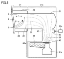
- FIG. 2 is a diagram illustrating an example of the mist generation unit.
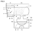
- FIG. 3 is a diagram illustrating another example of the mist generation unit.
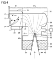
- FIG. 4 is a diagram illustrating another example of the mist generation unit.
- FIG. 5 is a diagram for explaining an electric field generation unit of a carbon nanotube aggregated wire manufacturing apparatus according to another embodiment of the present disclosure.
- FIG. 6 is a diagram for explaining a magnetic field generation unit of a carbon nanotube aggregated wire manufacturing apparatus according to another embodiment of the present disclosure.
- FIG. 7 is a diagram showing an example of carbon nanotubes used in an embodiment of the present disclosure.
- FIG. 1 is a diagram showing a typical configuration example of a carbon nanotube manufacturing apparatus according to an embodiment of the present disclosure.
- FIG. 2 is a diagram illustrating an example of the mist generation unit.
- FIG. 3 is a diagram illustrating another example
- FIG. 8 is a transmission electron microscope (TEM) image of carbon nanotubes according to an embodiment of the present disclosure.
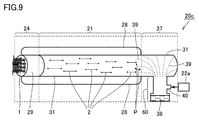
- FIG. 9 is a diagram illustrating a typical configuration example of a carbon nanotube aggregated wire manufacturing apparatus according to another embodiment of the present disclosure.
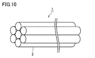
- FIG. 10 is a diagram illustrating a typical configuration example of a carbon nanotube assembly line according to an embodiment of the present disclosure.
- FIG. 11 is a diagram illustrating a typical configuration example of a carbon nanotube aggregated wire bundle according to an embodiment of the present disclosure.
- FIG. 12 is a transmission electron microscope (TEM) image of the carbon nanotube obtained in Sample 2-2.
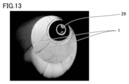
- FIG. 13 is an image of carbon nanotube assembly lines obtained in Sample 2-2.
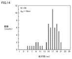
- FIG. 14 is a graph showing the particle size distribution of the catalyst particles in the carbon nanotube assembly line obtained in Example 2-2.
- FIG. 15 is an enlarged view of the second channel of the carbon nanotube collecting portion.
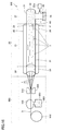
- FIG. 16 is a diagram showing a carbon nanotube aggregated wire bundle manufacturing apparatus according to an embodiment of the present disclosure.
- FIG. 17 is a diagram showing another example of the carbon nanotube aggregated wire bundle manufacturing apparatus according to an embodiment of the present disclosure.
- the present disclosure discloses a CNT manufacturing method capable of suppressing coarsening of catalyst particles, a CNT aggregate wire manufacturing method, a CNT aggregate wire bundle manufacturing method, a CNT manufacturing apparatus, a CNT aggregate wire manufacturing apparatus, and a CNT aggregate wire bundle manufacturing method.
- the purpose is to provide a device.
- the method for producing a carbon nanotube according to the present disclosure is A mist generating step of generating a mist containing catalyst particles and a liquid carbon source, And a growth step of growing carbon nanotubes from the catalyst particles by heating the mist.
- the mist preferably has an average particle size of 0.1 ⁇ m or more and 50 ⁇ m or less.
- the catalyst particles preferably contain iron.
- the use of iron as the catalyst particles is suitable from the viewpoint of mass production of CNTs.
- the mist generating step is A preparatory step of preparing a mist raw material liquid containing the catalyst particles and the liquid carbon source, It is preferable to include an atomization step of atomizing the mist raw material liquid by applying ultrasonic vibration to the mist raw material liquid.
- Atomization of the mist raw material liquid using ultrasonic vibration is suitable from the viewpoint of making the mist particle diameter uniform.
- the mist generating step is A preparatory step of preparing a mist raw material liquid containing the catalyst particles and the liquid carbon source, It is preferable to include an atomization step of atomizing the mist raw material liquid by passing the mist raw material liquid through a mesh while applying ultrasonic vibration to the mist raw material liquid.
- Atomization of the mist raw material liquid by passing the mist raw material liquid through the mesh while applying ultrasonic vibration is suitable from the viewpoint of making the mist particle diameter uniform.
- the mesh preferably has an opening with a diameter of 1 ⁇ m or more and 50 ⁇ m or less.
- the average particle diameter of the mist can be set to 0.1 ⁇ m or more and 50 ⁇ m or less.
- a method of manufacturing a carbon nanotube aggregated wire A mist generating step of generating a mist containing a plurality of catalyst particles and a liquid carbon source, A growth step of growing one or a plurality of carbon nanotubes from each of the plurality of catalyst particles by heating the mist; and a growth step, And a step of assembling the plurality of carbon nanotubes by orienting them in a direction along the longitudinal direction to obtain a carbon nanotube assembly line.
- the plurality of carbon nanotubes pass through the first channel
- the plurality of carbon nanotubes pass through one or more second flow channels arranged on the downstream side of the first flow channel,
- the cross-sectional area of each of the second flow paths is preferably smaller than the cross-sectional area of the first flow path.
- the temperature of the atmosphere on the downstream side of the second flow path is preferably lower than the temperature of the atmosphere on the upstream side of the second flow path. According to this, the CNTs are easily aggregated.
- the temperature of the atmosphere on the upstream side of the second flow path is 800° C. or higher and the temperature of the atmosphere on the downstream side of the second flow path is 600° C. or lower. According to this, the CNTs are easily aggregated.
- the temperature of the atmosphere in the second flow path is lower on the downstream side than on the upstream side,
- the temperature of the atmosphere at the downstream end in the second flow path is preferably 600°C or lower. According to this, the CNTs are easily aggregated in the second flow path.
- a first region in which the temperature of the atmosphere is 600° C. or lower is present on the downstream side in the second flow channel, and the length of the first region along the longitudinal direction of the second flow channel is 1 cm or more. Is preferred. According to this, the CNTs are easily aggregated in the second flow path.
- the cross-sectional area of each of the second flow paths is preferably 0.01 mm 2 or more and 4 mm 2 or less. According to this, the diameter of the CNT is easily reduced.
- the ratio S1/S2 of the cross-sectional area S1 of the first flow channel to the cross-sectional area S2 of each of the second flow channels is preferably 100 or more and 1,000,000 or less. According to this, the CNTs are likely to expand and the diameter of the CNTs is easily reduced.
- the diameter of the plurality of carbon nanotubes is reduced in the assembling step. According to this, it is possible to obtain a CNT aggregate line including CNTs having a small diameter.
- the length of each of the second flow paths is preferably 10 mm or more and 200 mm or less. According to this, the CNTs are likely to expand and the diameter of the CNTs is easily reduced.
- a method of manufacturing a carbon nanotube aggregated wire bundle according to an aspect of the present disclosure, A mist generating step of generating a mist containing a plurality of catalyst particles and a liquid carbon source, A growth step of growing one or a plurality of carbon nanotubes from each of the plurality of catalyst particles by heating the mist; An assembling step of obtaining a plurality of carbon nanotube assembly lines by assembling the plurality of carbon nanotubes by orienting them in a direction along the longitudinal direction thereof, A method of manufacturing a carbon nanotube aggregated line bundle, which comprises a bundle step of orienting the plurality of carbon nanotube aggregated lines in a direction along a longitudinal direction thereof to bundle them to obtain a carbon nanotube aggregated line bundle.
- the bundling step includes an attaching step of attaching a volatile liquid to the plurality of carbon nanotube assembly lines and an evaporation step of evaporating the volatile liquid attached to the plurality of carbon nanotube assembly lines. Is preferred. According to this, the density of the obtained CNT aggregate wire bundle is improved.
- the attaching step is performed before orienting the plurality of carbon nanotube assembly lines in a direction along the longitudinal direction thereof and bundling them.
- the carbon nanotube filaments can be brought close to each other and firmly bonded to each other in the process of evaporating the liquid that has penetrated into the voids between the carbon nanotube filaments.
- the attaching step is performed after the plurality of carbon nanotube assembly lines are aligned and bundled in a direction along the longitudinal direction thereof.
- the carbon nanotube filaments can be brought close to each other and firmly bonded to each other in the process of evaporating the liquid that has penetrated into the voids between the carbon nanotube filaments.
- the bundling step is preferably performed while applying tension to the plurality of carbon nanotube assembly lines. According to this, the strength of the obtained CNT aggregate wire bundle is improved.
- a carbon nanotube manufacturing apparatus according to an aspect of the present disclosure, A mist generating section that generates a mist containing catalyst particles and a liquid carbon source, A carbon nanotube manufacturing apparatus, comprising: a tubular carbon nanotube growth unit that is connected to the mist generation unit and grows the carbon nanotubes from the catalyst particles by heating the mist.
- the mist generator has a vibrator, It is preferable that the vibrator atomizes the mist raw material liquid to generate the mist by applying ultrasonic vibration to the mist raw material liquid containing the catalyst particles and the liquid carbon source.
- Atomization of the mist raw material liquid using ultrasonic vibration is suitable from the viewpoint of making the mist particle diameter uniform.
- the mist generating section has a mesh arranged so as to face the vibration surface of the vibrator,
- the vibrator atomizes the mist raw material liquid supplied between the vibrating surface and the mesh by passing the mist raw material liquid through the mesh while applying the ultrasonic vibration to generate the mist.
- Atomization of the mist raw material liquid by passing the mist raw material liquid through the mesh while applying ultrasonic vibration is suitable from the viewpoint of making the mist particle diameter uniform.
- the mesh preferably has an opening with a diameter of 1 ⁇ m or more and 50 ⁇ m or less.
- the average particle diameter of the mist can be set to 0.1 ⁇ m or more and 50 ⁇ m or less.
- a carbon nanotube aggregated wire manufacturing apparatus A plurality of catalyst particles, and a mist generating section that generates a mist containing a liquid carbon source, A tubular carbon nanotube growth part, which is connected to the mist generation part and grows one or a plurality of carbon nanotubes from each of the plurality of catalyst particles by heating the mist, A carbon nanotube arranged on one end side of the carbon nanotube growth portion and obtained by aligning a plurality of carbon nanotubes obtained in the carbon nanotube growth portion in a direction along the longitudinal direction to obtain a carbon nanotube assembly line
- a carbon nanotube aggregated wire manufacturing apparatus comprising: an aggregate part.
- the carbon nanotube growth part has a first flow path therein,
- the carbon nanotube collecting portion has one or more second flow paths therein,
- the cross-sectional area of each of the second flow paths is preferably smaller than the cross-sectional area of the first flow path.
- the aggregate of carbon nanotubes preferably has a honeycomb structure. According to this, a tensile force can be applied to the CNTs in the carbon nanotube aggregated portion, and at the same time, a plurality of carbon nanotubes can be brought close to each other in an aligned state.
- the honeycomb structure is a honeycomb structure having a plurality of second flow paths formed of a plurality of through holes,
- the cross-sectional area of each of the second flow paths is preferably 0.01 mm 2 or more and 4 mm 2 or less.
- the diameter of the CNT is easily reduced.
- the ratio S1/S2 of the cross-sectional area S1 of the first flow path to the cross-sectional area S2 of each of the second flow paths is 100 or more and 1,000,000 or less. According to this, the CNTs are likely to expand and the diameter of the CNTs is easily reduced.
- the diameter of the plurality of carbon nanotubes is reduced in the carbon nanotube aggregated portion. According to this, it is possible to obtain a CNT aggregate line including CNTs having a small diameter.
- the length of each of the second flow paths of the carbon nanotube collecting portion is 10 mm or more and 200 mm or less. According to this, the CNTs are likely to expand and the diameter of the CNTs is easily reduced.
- a carbon nanotube aggregated wire bundle manufacturing apparatus according to an aspect of the present disclosure, The above carbon nanotube assembly line manufacturing apparatus, An apparatus for producing a bundle of carbon nanotube aggregate lines, comprising: a bundle portion obtained by orienting a plurality of aggregate lines of carbon nanotubes obtained by the apparatus for producing aggregate carbon nanotube lines in a direction along a longitudinal direction thereof to obtain a bundle of aggregate carbon nanotube lines. Is.
- the bundle section includes a liquid attachment device that attaches a volatile liquid to the plurality of carbon nanotube assembly lines.
- the bundle portion may include a winding device that winds the plurality of carbon nanotube assembly lines in a direction along a longitudinal direction of the plurality of carbon nanotube assembly lines while applying tension to the plurality of carbon nanotube assembly lines. preferable.
- the notation in the form of “AB” means the upper and lower limits of the range (that is, A or more and B or less), and when A has no unit described and B only has a unit, The unit of B and the unit of B are the same.
- the upper limit of the range being C means that the upper limit of the range is C or lower
- the lower limit of the range being D means that the lower limit of the range is D or higher.
- the method for manufacturing the carbon nanotube according to the first embodiment comprises a step of generating a mist containing catalyst particles and a liquid carbon source, and heating the mist to grow carbon nanotubes from the catalyst particles, thereby producing a plurality of carbon nanotubes. And a growth step of growing.
- the carbon nanotube manufacturing method may use the carbon nanotube manufacturing apparatus 50 shown in FIG. 1, for example.
- the carbon nanotube manufacturing apparatus 50 includes a mist generating section 37 for generating a mist 39 containing catalyst particles and a liquid carbon source, a gas supply section 22 for supplying a carrier gas into the mist generating section 37, and a mist generating section.
- a tubular carbon nanotube growth portion (hereinafter also referred to as a CNT growth portion) 21 connected to 37 can be provided.
- mist generating step a mist 39 containing catalyst particles and a liquid carbon source is generated.
- the mist generating step is performed using the mist generating device 60.
- the mist generating step is a preparation step of preparing a mist raw material liquid containing catalyst particles and a liquid carbon source, and an atomization step of atomizing the mist raw material liquid by applying ultrasonic vibration to the mist raw material liquid. Can be included.
- the average particle diameter of the mist obtained by atomizing the mist raw material liquid is preferably 0.1 ⁇ m or more and 50 ⁇ m or less, more preferably 1 ⁇ m or more and 40 ⁇ m or less, still more preferably 10 ⁇ m or more and 30 ⁇ m or less. If the average particle size of the mist is less than 0.1 ⁇ m, the growth of the catalyst having a particle size suitable for CNT growth tends to be suppressed. On the other hand, when the average particle diameter of the mist exceeds 50 ⁇ m, enlargement of the catalyst particles is promoted, and the growth efficiency of CNT tends to decrease.
- the “average particle diameter” of the mist means the median diameter (d50) in the volume-based particle size distribution (volume distribution), and is the average particle diameter for all mist particles contained in the mist. Means In addition, in this specification, “average particle diameter” may be simply described as “particle diameter.”
- the particle size of each mist particle for calculating the mist particle size can be measured by the following method. First, a mist is generated using a mist generator. A particle size distribution is obtained by irradiating the generated mist with laser light using a dynamic light scattering particle size distribution measuring device and detecting the intensity distribution of scattered light due to Brownian motion depending on the particle size.
- the catalyst particles in the mist raw material liquid include, for example, at least one metal element selected from the group consisting of iron, nickel, cobalt, molybdenum, gold, silver, copper, yttrium, chromium, palladium, platinum and tungsten. Particles can be used.
- the catalyst particles containing a metal element means that the catalyst particles contain other elements (for example, oxygen, sulfur, etc.) together with the metal element, and that the catalyst particles contain only the metal element. means.
- the catalyst particles in the mist raw material liquid preferably contain iron.
- the catalyst particles e.g., iron oxide (Fe 2 O 3)
- the catalyst particles are more preferably made of iron oxide.
- iron oxide as the catalyst particles in the mist raw material liquid is suitable from the viewpoint of mass production of CNTs. Therefore, when the catalyst particles in the mist raw material liquid contain iron oxide, it is possible to mass-produce long CNT aggregate lines.
- the average particle size of the catalyst particles in the mist raw material liquid is preferably 0.6 nm or more and less than 200 nm. According to this, the average particle diameter of the catalyst particles contained in the CNT can be set to 0.6 nm or more and less than 30 nm.
- the average particle diameter of the catalyst particles in the mist raw material liquid is more preferably 1 nm or more and 100 nm or less, still more preferably 2 nm or more and 50 nm or less.
- the “average particle diameter” of the catalyst particles in the mist raw material liquid means the median diameter (d50) in the volume-based particle size distribution (volume distribution), and all catalyst particles contained in the mist raw material liquid are targeted. It means that the average particle size is In addition, in this specification, “average particle diameter” may be simply described as “particle diameter.”
- ethanol As the liquid carbon source, ethanol, methanol, isopropyl alcohol, benzene, toluene, xylene can be used.
- ethanol is suitable because it is a widely used reagent and has extremely low toxicity to the human body, and since it contains oxygen, it can suppress the formation of amorphos carbon.
- the mist raw material liquid may contain carbon disulfide, thiophene, etc. in addition to the catalyst particles and the liquid carbon source. Carbon disulfide and thiophene have a function as a co-catalyst.
- the content of the catalyst particles in the mist raw material liquid is preferably 0.01% by mass or more and 5% by mass or less, more preferably 0.1% by mass or more and 4% by mass or less, and 0.5% by mass or more and 2% by mass or less. More preferable.
- the content of the catalyst particles in the mist raw material liquid is less than 0.01% by mass, the production efficiency of CNT tends to decrease.
- the content of the catalyst particles in the mist raw material liquid exceeds 5% by mass, the catalyst particles tend to become coarse.
- the content of the liquid carbon source in the mist raw material liquid is preferably 95% by mass or more and 99.99% by mass or less, more preferably 96% by mass or more and 99.9% by mass or less, and 98% by mass or more and 99.5% by mass. % Or less is more preferable. If the content of the liquid carbon source in the mist raw material liquid is less than 95% by mass, the production efficiency of CNTs tends to decrease. On the other hand, when the content of the liquid carbon source in the mist raw material liquid exceeds 99.99% by mass, the carbon source concentration is high with respect to the amount of the catalyst added, so that the amount of amorphous carbon produced tends to increase.
- FIGS. 2 to 4 are diagrams each showing an example of the mist generator 37 (FIG. 1).
- the mist generating section 37a shown in FIG. 2 includes a reaction tube 31 that is continuous with the reaction tube that constitutes the CNT growth section 21, and a mist generating device 60a that is connected to the reaction tube 31. That is, the mist generating part 37 a is connected to the CNT growing part 21.
- the mist generating device 60a has a horn oscillator 41a and a mesh 42 arranged so as to face the vibrating surface of the horn oscillator 41a.
- the mist raw material liquid 38 is supplied between the vibrating surface of the horn vibrator 41 a and the mesh 42.
- the horn oscillator 41a applies ultrasonic vibration to the mist raw material liquid 38 supplied between the vibrating surface of the horn oscillator 41a and the mesh 42.
- the mist raw material liquid 38 passes through the holes of the mesh and is atomized into mist 39.
- a connection part 45 connected to the reaction tube 31 is provided above the mesh 42.
- the mist 39 generated by the mist generating device 60 a is supplied to the inside of the reaction tube 31 via the connecting portion 45.
- connection part 45 may be provided with a gas inlet 40 for taking in gas from the outside.
- a carrier gas such as argon is introduced from the gas inlet 40.
- the carrier gas By introducing the carrier gas, the supply of mist into the reaction tube 31 can be promoted. Further, by changing the flow velocity of the carrier gas, the flow velocity of the gas in the CNT growth portion and the CNT extension portion can be adjusted.
- a mesh is defined as a thin plate having a plurality of minute openings.
- the shape of the opening include a circle, an ellipse, and a polygon. Among them, the circular shape is preferable from the viewpoint of generating a mist having a uniform particle size.
- the mist raw material liquid 38 passes through the holes of the mesh 42 and is atomized. Therefore, by adjusting the size of the diameter of the openings of the mesh, the average particle size of the mist can be adjusted to a desired size.
- the mesh has an opening diameter of preferably 1 ⁇ m or more and 50 ⁇ m or less, more preferably 3 ⁇ m or more and 40 ⁇ m or less, still more preferably 5 ⁇ m or more and 30 ⁇ m or less.
- the diameter of the opening is 1 ⁇ m or more and 50 ⁇ m or less, the average particle diameter of the mist after passing through the mesh can be 0.1 ⁇ m or more and 50 ⁇ m or less. If the diameter of the opening is less than 1 ⁇ m, clogging tends to occur. On the other hand, when the diameter of the opening exceeds 50 ⁇ m, coarsening of the catalyst particles tends to occur in the heat treatment step in the CNT growth process.
- the diameter of the opening is defined as the diameter of a circle having the same opening area (equivalent circle diameter of the same opening area).
- the number of openings of the mesh is preferably 2 /mm 2 or more and 400/mm 2 or less, more preferably 10/mm 2 or more and 200/mm 2 or less, and 20/mm 2 or more 100/ mm 2 or less is more preferable. If the number of openings is less than 2/mm 2 , the mist generation efficiency tends to be significantly reduced. On the other hand, when the number of openings exceeds 400/mm 2 , the droplets tend to condense after the mist is generated and hinder the catalyst from becoming fine particles.
- the thickness of the mesh is preferably 1 ⁇ m or more and 500 ⁇ m or less, more preferably 5 ⁇ m or more and 250 ⁇ m or less, still more preferably 10 ⁇ m or more and 100 ⁇ m or less. If the thickness of the mesh is less than 1 ⁇ m, the resistance to repeated use tends to decrease. On the other hand, when the thickness of the mesh exceeds 500 ⁇ m, ultrasonic vibration cannot be efficiently applied and the generation of mist tends to be hindered.
- the material of the mesh may be stainless steel, for example.
- the frequency of the horn oscillator is preferably 50 kHz or more and 400 kHz or less, more preferably 70 kHz or more and 300 kHz or less, and further preferably 100 kHz or more and 200 kHz or less. If the frequency of the horn oscillator is less than 50 kHz, the mist generation efficiency tends to decrease, which is not preferable. On the other hand, if the frequency of the horn vibrator exceeds 400 kHz, it tends to induce early deterioration of the mesh, which is not preferable.
- the mist generating section 37b shown in FIG. 3 includes a reaction tube 31 that is continuous with a reaction tube that constitutes the CNT growth section 21, and a mist generating device 60b that is connected to the reaction tube 31. That is, the mist generation part 37b is connected to the CNT growth part 21.
- the mist generating device 60b includes a first container 47 holding the water 43, a vibrator 41b arranged at the bottom of the first container 47, and a second container 48 arranged inside the first container 47. With. At least a part of the outer surface of the second container 48 is in contact with the water 43.
- the mist raw material liquid 38 is housed inside the second container 48.
- the second container is provided with a gas inlet 40 for taking in gas from the outside and a connecting portion 45 connected to the reaction tube 31.
- a carrier gas such as argon is introduced from the gas inlet 40.
- the carrier gas By introducing the carrier gas, the supply of mist into the reaction tube 31 can be promoted. Further, by changing the flow velocity of the carrier gas, the flow velocity of the gas in the CNT growth portion and the CNT extension portion can be adjusted.
- the vibrator 41b vibrates to give ultrasonic vibration energy to water.
- the ultrasonic vibration energy is concentrated on the surface of the mist raw material liquid 38, and the mist raw material liquid 38 is atomized into mist 39 by the action of vibration (cavitation effect).
- the mist 39 is supplied into the reaction tube 31 via the connecting portion 45 together with the gas taken in from the gas inlet 40.
- the mist generating section 37c shown in FIG. 4 includes a reaction tube 31 that is continuous with a reaction tube that constitutes the CNT growth section 21, and a mist generating device 60c that is connected to the reaction tube 31. That is, the mist generation part 37c is connected to the CNT growth part 21.
- the mist generating device 60 c includes a container 49 in which the mist raw material liquid 38 is stored, an air inlet 44 for introducing compressed air generated from a compressor (not shown) into the container 49, and an upper portion of the air inlet 44.
- the nozzle portion 52 is arranged continuously, the baffle 51 arranged above the nozzle portion 52, and a pipe 53 for allowing the mist raw material liquid 38 to reach the vicinity of the nozzle portion 52.
- mist raw material liquid 38 is sucked up to the upper portion of the pipe 53, collides with the baffle 51, and atomizes to become the mist 39.
- the mist 39 is supplied into the reaction tube 31 via the connection portion 45.
- connection part 45 may be provided with a gas inlet 40 for taking in gas from the outside.
- a carrier gas such as argon is introduced from the gas inlet 40.
- the carrier gas By introducing the carrier gas, the supply of mist into the reaction tube 31 can be promoted. Further, by changing the flow velocity of the carrier gas, the flow velocity of the gas in the CNT growth portion and the CNT extension portion can be adjusted.
- the carbon nanotubes are grown from the catalyst particles P by heating the mist 39.
- the growth process is performed inside the CNT growth unit 21.
- the mist 39 is illustrated as existing near the upstream side of the CNT growth portion 21, but the present invention is not limited to this.
- the mist 39 may be present in the entire CNT growth portion 21.
- the temperature for heating the mist is preferably 800°C or higher and 1200°C or lower. That is, it is preferable that the growth step is performed under a temperature condition of 800° C. or higher and 1200° C. or lower. If the temperature is lower than 800°C, the growth rate of CNTs tends to be slow. On the other hand, if the temperature exceeds 1200° C., the content of impurity carbon tends to increase.
- the temperature condition of the growth step is more preferably 900° C. or higher and 1150° C. or lower, further preferably 950° C. or higher and 1050° C. or lower.
- the lower limit of the average flow velocity of the carrier gas supplied from the gas inlet 40 in the CNT growth part is 0.05 cm/sec, preferably 0.1 cm/sec, and more preferably 0.2 cm/sec.
- the upper limit of the average flow velocity in the CNT growth portion 21 is preferably 10 cm/sec, more preferably 5 cm/sec. If the average flow velocity of the carrier gas in the CNT growth portion 21 is less than the above lower limit, the mist tends to condense and liquefy in the non-heated portion in the core tube.
- the lower limit of the Reynolds number of the flow of the carrier gas supplied from the gas inlet 40 in the CNT growth part 21 is preferably 0.01, and more preferably 0.05.
- the upper limit of the Reynolds number is 1000, preferably 100, and more preferably 10. If the Reynolds number is less than the lower limit, the design of the device is excessively restricted, and thus the carbon nanotube assembly line manufacturing apparatus 20 may be unnecessarily expensive, or the carbon nanotube manufacturing efficiency may be unnecessarily reduced. Tend. When the Reynolds number exceeds the upper limit, the flow of the carbon-containing gas is disturbed and the generation of carbon nanotubes on the catalyst particles P tends to be hindered.
- the growth step it is preferable to grow the carbon nanotubes between the plurality of catalyst particles by separating the plurality of catalyst particles in a close contact state while heating the mist 39 in the flow of the carrier gas to obtain CNT.
- the catalyst particles in a close contact state in the mist separate, and at the same time, CNT grows between the catalyst particles using the liquid carbon source contained in the mist as a raw material.
- the carrier gas supplied from the gas supply unit 22 for example, argon, helium, hydrogen, nitrogen, neon, krypton or the like can be used.
- the CNT manufacturing method according to the present embodiment may include an extension step after the growth step.
- the extending step the carbon nanotubes in the floating state obtained in the growing step are stretched by applying a tensile force.
- the extension process is performed inside the CNT growth unit 21 and the CNT extension unit 30, or inside the CNT extension unit 30.
- the extension step is preferably performed on the downstream side of the carbon-containing gas of the CNT growth section 21, that is, on the CNT extension section 30 side.
- the tensile force is preferably applied to the carbon nanotubes by changing the flow rate of the carrier gas. For example, by making the average flow velocity of the carrier gas on the downstream side larger than the average flow velocity of the carrier gas on the upstream side, a tensile force in the direction toward the downstream side can be applied to the CNT.
- the tensile force acts on the ends of the carbon nanotubes, whereby the carbon nanotubes extending from the catalyst particles P are stretched and plastically deformed to be reduced in diameter and elongated in the longitudinal direction.
- the carbon nanotubes are oriented and stretched in the direction along the flow of the carrier gas. According to this, it is considered that the carbon nanotubes are hard to bend, and it is possible to obtain the linear carbon nanotubes in which the tube portion T is composed only of carbon of a six-membered ring. Carbon nanotubes consisting only of six-membered carbon are less prone to deterioration and can maintain quality.
- the average flow velocity of the carrier gas on the downstream side is preferably 0.051 cm/sec or more and 10.001 cm/sec or less, and more preferably 0.201 cm/sec or more and 5.001 cm/sec or less. If the average flow velocity of the carrier gas on the downstream side is less than 0.051 cm/sec, the elongation rate of the carbon nanotubes tends not to be sufficiently higher than the growth rate. On the other hand, when the average flow velocity of the carrier gas on the downstream side exceeds 10.001 cm/sec, the formation of carbon nanotubes tends to be hindered by separating the carbon nanotubes from the catalyst particles P and stopping the growth of the carbon nanotubes. ..
- the average flow velocity of the above carrier gas on the upstream side is preferably 0.050 cm/sec or more and 10.000 cm/sec or less, and more preferably 0.200 cm/sec or more and 5.000 cm/sec or less. If the average flow velocity of the carrier gas on the upstream side is less than 0.050 cm/sec, the wind pressure is insufficient and the growth of carbon nanotubes formed between the catalyst particles P tends to be stagnant. On the other hand, when the average flow velocity of the carrier gas on the upstream side exceeds 10.000 cm/sec, the carbon nanotubes are likely to be separated from the catalyst particles P to stop the growth of the carbon nanotubes, thereby inhibiting the formation of the carbon nanotubes. ..
- the carrier gas As a method of increasing the average flow velocity of the downstream side of the carrier gas higher than the average flow velocity of the upstream side of the carrier gas, for example, the cross-sectional area of the hollow portion through which the carrier gas passes, than the upstream side of the carrier gas, the carrier gas It is possible to reduce the size of the downstream side of. More specifically, the cross section of the hollow portion through which the carbon-containing gas passes in the CNT extension portion (corresponding to the downstream side) is larger than the cross-sectional area of the hollow portion through which the carbon-containing gas passes in the CNT growth portion (corresponding to the upstream side). The area can be reduced. According to this, an acceleration field is generated in the vicinity of the region where the cross-sectional area of the hollow portion is small, and the flow velocity of the carrier gas increases.
- FIG. 5 is a diagram showing the periphery of the magnetic field generator.
- the electric wire 55 is installed in a coil shape around the reaction tube 31, and the electric wire is energized to generate the inside of the reaction tube 31.
- the magnetic force directly acts on the metal contained in the CNT, whereby the CNT can be oriented and extended in the direction along the magnetic field line 32 in the reaction tube.
- FIG. 6 is a diagram showing the vicinity of the electric field generator.
- a + electrode 33 made of a conductive material is installed on the downstream side of the carbon-containing gas
- a ⁇ electrode 34 made of a conductive material is installed on the upstream side, and the center of the reaction tube 31 is installed.
- a tensile force derived from the electric field can be applied to the CNT.
- an electrostatic force directly acts on the CNT and the metal contained in the CNT, and the CNT can be oriented and extended in the direction along the line of electric force.
- the tube portion should be formed at an extremely high speed as compared with the growth speed of the carbon nanotubes on the catalyst particles P. You can Therefore, long carbon nanotubes can be formed in a relatively short time. Therefore, a sufficiently long carbon nanotube can be formed even if the time for which the condition for continuously growing the carbon nanotube on the catalyst particle P can be maintained is short.
- the tensile force acts on the carbon nanotubes on the catalyst particles P to promote the uptake of carbon atoms at the growth points of the carbon nanotubes. It is considered that this makes it possible to further increase the growth rate of the carbon nanotubes and thus the increase rate of the length of the obtained carbon nanotubes.
- the carbon nanotubes are hard to bend, and the tube portion T is a linear body formed of a sheet made of only a six-membered ring carbon. It is thought that the carbon nanotubes of Carbon nanotubes consisting only of six-membered carbon are less prone to deterioration and can maintain quality.
- the length of CNT obtained by the elongation step is preferably 10 ⁇ m or more, more preferably 100 ⁇ m or more.
- the length of the carbon nanotube is 100 ⁇ m or more, it is suitable from the viewpoint of producing the CNT aggregate line.
- the upper limit of the length of the carbon nanotube is not particularly limited, but 600 mm or less is preferable from the viewpoint of production.
- the length of CNT can be measured by observing with a scanning electron microscope.
- the carbon nanotube can have a known structure.
- a single-walled carbon nanotube in which only one layer of carbon (graphene) is in a tubular shape a double-walled carbon nanotube or a multi-walled carbon nanotube in which a plurality of layers of carbon are laminated in a tubular shape, a bottom
- An example is a cup-stacked nanotube having a structure in which graphene in the shape of a paper cup that has been removed is laminated.
- the shape of the carbon nanotube is not particularly limited, and includes either a closed tip or an open tip.
- the catalyst particles P used in the production of the carbon nanotubes may be attached to one or both ends of the tube portion T of the carbon nanotube 2.
- a cone portion C made of conical graphene may be formed at one or both ends of the tube portion T of the carbon nanotube 2.
- the case where the catalyst particles are attached to both ends of the carbon nanotube means that (i) the catalyst particles are attached to both ends of the carbon nanotube so that at least a part thereof is exposed outside the carbon nanotube. Or (ii) a state where the catalyst particles are completely embedded and attached inside both ends of the carbon nanotube (see FIG. 8), or (iii) the catalyst particles are at least at one end of the carbon nanotube. A part of the carbon nanotube is exposed and attached to the outside of the carbon nanotube, and the other end is completely embedded and attached to the inside of the carbon nanotube.
- the length of the carbon nanotube can be appropriately selected depending on the application.
- the length of the carbon nanotube is, for example, preferably 10 ⁇ m or more, more preferably 100 ⁇ m or more. In particular, when the length of the carbon nanotube is 100 ⁇ m or more, it is suitable from the viewpoint of producing the CNT aggregate line.
- the upper limit of the length of the carbon nanotube is not particularly limited, but 600 mm or less is preferable from the viewpoint of production.
- the length of CNT can be measured by observing with a scanning electron microscope.
- the diameter of the carbon nanotube is preferably 0.6 nm or more and 20 nm or less, more preferably 1 nm or more and 10 nm or less. In particular, it is preferable that the diameter of the carbon nanotube is 1 nm or more and 10 nm or less from the viewpoint of heat resistance under oxidizing conditions.
- the diameter of carbon nanotube means the average outer diameter of one CNT.
- the average outer diameter of the CNT is obtained by directly observing a cross section of the CNT at two arbitrary positions with a transmission electron microscope, and measuring the outer diameter which is the distance between the two most distant points on the outer circumference of the CNT in the cross section. It is obtained by calculating the average value of the obtained outer diameters.
- the CNT includes a cone portion at one or both ends, the diameter is measured at a place excluding the cone portion.
- the catalyst particles When the catalyst particles are attached to the carbon nanotubes, the catalyst particles preferably have a particle size of 0.6 nm or more and less than 30 nm.
- the catalyst particles are derived from the catalyst (ferrocene (Fe(C 5 H 5 ) 2 ), iron oxide powder (Fe 2 O 3 ), etc.) used in the production of the CNT assembly line.
- the particle diameter of the attached catalyst particles is as small as less than 30 nm, and the catalyst particles are not coarsened. Therefore, the catalyst particles may affect the electrical conductivity characteristics of the CNT. Absent. Therefore, the CNT can be elongated while maintaining the electrical conductivity that the CNT originally has.
- the particle size of the catalyst particles attached to the CNTs can be measured by the following method. First, carbon nanotubes are observed at a magnification of 100,000 to 500,000 times using a transmission microscope (TEM). Next, in this TEM image, the outer diameter, which is the distance between the two points that are most distant from each other on the outer circumference of each catalyst particle, is measured.
- TEM transmission microscope
- the type of catalyst particles and their content can be confirmed and measured by energy dispersive X-ray analysis (Energy dispersive X-ray spectroscopy, EDX).
- the total content of the catalyst particles in the CNT is preferably 0.1% or more and 50% or less, more preferably 1% or more and 40% or less, still more preferably 5% or more and 20% or less, based on the number of atoms.
- FIG. 1 A carbon nanotube manufacturing apparatus used in the carbon nanotube manufacturing method according to the first embodiment will be described with reference to FIG.
- the carbon nanotube manufacturing apparatus 50 shown in FIG. 1 is connected to a mist generating section 37 for generating a mist 39 containing catalyst particles and a liquid carbon source, and is connected to the mist generating section 37 and heats the mist 39.
- a tubular carbon nanotube growth portion 21 (hereinafter also referred to as a CNT growth portion) for growing carbon nanotubes from the catalyst particles.
- the carbon nanotube manufacturing apparatus may further include a gas supply unit 22 that supplies a carrier gas into the mist generation unit 37.
- the mist generating section 37 generates a mist 39 containing a plurality of catalyst particles and a liquid carbon source.
- ultrasonic vibration is applied to the mist raw material liquid 38 containing the catalyst particles and the liquid carbon source, whereby the mist raw material liquid 38 can be atomized to generate the mist 39.
- the mist generator 37 (FIG. 18) can have the configuration shown in FIGS. 2 to 4, for example.
- the specific configuration of the mist generation unit shown in FIGS. 2 to 4 is described in the first embodiment, and therefore the description thereof will not be repeated.
- the carbon nanotube growth portion 21 has a tubular shape made of, for example, a quartz tube. In the CNT growth section 21, the carbon nanotubes 2 are formed on the catalyst particles P using a liquid carbon source contained in the mist as a raw material.
- the carbon nanotube growth section 21 is placed in an electric furnace 28 and heated by a heater (not shown).
- the gas supply unit 22 supplies the carrier gas into the mist generation unit 37.
- the gas supply unit 22 can be configured to have a gas cylinder (not shown) and a flow rate control valve (not shown).
- the carrier gas supplied from the gas supply unit 22 passes through the mist generation unit 37 and reaches the CNT growth unit 21.
- the type of carrier gas supplied from the gas supply unit 22, the average flow velocity in the CNT growth unit, and the Reynolds number of the flow in the CNT growth unit are the same as those described in the CNT manufacturing method of the first embodiment. The description will not be repeated because it can be done.
- the gas supply unit 22 can repeatedly change the amount of carrier gas supplied to the CNT growth unit 21. As a result, the flow rate of the carrier gas in the CNT growth part 21 is increased or decreased, and the separation of the plurality of agglomerated catalyst particles is promoted, so that the number of carbon nanotubes obtained can be increased.
- the CNT manufacturing apparatus can include, in addition to the above-described configuration, a CNT expansion unit that expands CNTs, a magnetic field generation unit that generates a magnetic field, an electric field generation unit that generates an electric field, and the like.
- the method for producing a carbon nanotube aggregated wire according to the fourth embodiment includes a mist generating step of generating a mist containing a plurality of catalyst particles and a liquid carbon source, and heating the mist to obtain the plurality of catalyst particles. From each of the above, a growth step of growing one or a plurality of carbon nanotubes, and a collection step of orienting and collecting the plurality of carbon nanotubes in a direction along the longitudinal direction to obtain a carbon nanotube assembly line are included.
- the carbon nanotube aggregated wire manufacturing apparatus 20c shown in FIG. 9 can be used.
- the carbon nanotube assembly line manufacturing apparatus 20c is connected to the mist generating section 37 for generating a mist containing a plurality of catalyst particles and a liquid carbon source, and the mist generating section 37.
- the one or more carbon nanotubes are grown from each of the catalyst particles P, and the tubular carbon nanotube growth portion 21 is arranged on one end side (the left end portion in FIG. 18) of the carbon nanotube growth portion 21.
- the carbon nanotube collecting portion 24 may be provided with a plurality of carbon nanotubes obtained in the carbon nanotube growing portion 21 that are oriented and collected in a direction along the longitudinal direction to obtain a carbon nanotube collecting line.
- mist generating step and the growing step in the fourth embodiment are the same steps as the mist generating step and the growing step described in the first embodiment, respectively, the description thereof will not be repeated.
- the method for manufacturing the CNT aggregate wire according to the fourth embodiment may include an extension step after the growth step.
- the extension process in the fourth embodiment is the same as the extension process described in the first embodiment, and therefore the description thereof will not be repeated.
- ⁇ Assembling process> Next, a plurality of carbon nanotubes are oriented and assembled in a direction along the longitudinal direction to obtain a carbon nanotube assembly line.
- the collecting step is performed inside the CNT collecting unit 24.
- the cross-sectional area of the hollow part of the CNT collecting part through which the carrier gas passes is smaller than the cross-sectional area of the hollow part of the CNT growing part through which the carrier gas passes.
- the CNT collecting portion may be a honeycomb structure, and the through holes of the honeycomb structure may be arranged so that the longitudinal direction thereof is along the flow of the carrier gas.
- the honeycomb structure means a porous body having a large number of thin cylindrical through holes, as shown in the honeycomb structure 29 of FIG.
- the cross-sectional area of one through hole is preferably 0.005 mm 2 or more and 100 mm 2 or less, preferably 0.01 mm 2 or more and 100 mm 2 or less, and 0.05 mm 2 or more and 100 mm 2 or less. Is preferable, 0.1 mm 2 or more and 50 mm 2 or less is preferable, and 0.5 mm 2 or more and 10 mm 2 or less is preferable.
- the cross-sectional area of one through hole is less than 0.005 mm 2 , the CNT tends to be clogged inside the through hole.
- the cross-sectional area of one through hole exceeds 100 mm 2 , the CNTs do not sufficiently approach each other, and there is a tendency that they cannot be aggregated.
- the cross-sectional area of the CNT aggregate portion is more than 4 mm 2 , the CNTs may not be sufficiently aggregated, and the CNT simplex may be present together with the CNT aggregate line. Therefore, when it is desired to increase the recovery amount as the CNT aggregate line, the cross-sectional area of the CNT aggregate portion is preferably 0.005 mm 2 or more and 4 mm 2 or less, and more preferably 0.01 mm 2 or more and 4 mm 2 or less. preferable.
- the length of the honeycomb structure in the direction along the through holes is preferably 1 mm or more and 1 m or less, more preferably 10 mm or more and 50 cm or less, and further preferably 15 mm or more and 10 cm or less. preferable.
- the length in the direction along the through holes of the honeycomb structure is less than 1 mm, the CNT suspended in the gas phase is not sufficiently accelerated, and the growth promoting action tends to be suppressed.
- the length of the honeycomb structure in the direction along the through hole exceeds 1 m, the amount of CNT deposited on the inner wall of the through hole increases, and CNT collection tends to be difficult.
- the length of the CNT extension is less than 20 mm, the CNTs may not be aggregated sufficiently, and there may be a single CNT together with the CNT assembly line. Therefore, when it is desired to increase the recovery amount as the CNT aggregate line, it is preferable that the length of the CNT extension part is 20 mm or more and 1 m or less.
- the average flow velocity of the carrier gas in the CNT collecting portion is preferably 0.05 cm/sec or more and 10 cm/sec or less, and more preferably 0.2 cm/sec or more and 5 cm/sec or less. If the average flow rate of the carrier gas is less than 0.05 cm/sec, a thin film non-oriented CNT tends to be obtained. On the other hand, when the average flow rate of the carrier gas exceeds 10 cm/sec, the carrier gas that has reached the CNT collecting portion unreacted undergoes an incomplete decomposition reaction and tar tends to adhere.
- Extending process and assembly process can be performed at the same time. Further, after the extension step is performed, the extension step and the assembly step can be performed at the same time. For example, when a honeycomb structure is used as the CNT collecting portion, the CNT expansion and collecting are simultaneously performed in the through holes of the honeycomb structure.
- the carrier gas is continuously supplied to the mist generating part, the CNT growing part and the CNT aggregating part so that the CNT aggregate line can be continuously manufactured without any limitation in length. Is possible.
- the length of the CNT assembly line can be appropriately adjusted by adjusting the flow rate of the carrier gas, the supply time, and the like.
- the length of the CNT assembly line obtained by the assembly step is preferably 100 ⁇ m or more, more preferably 1000 ⁇ m or more, still more preferably 10000 ⁇ m or more.
- the upper limit of the length of the CNT aggregate line is not particularly limited, but from the viewpoint of manufacturing, it is preferably 1 m or less.
- the length of the CNT aggregate line can be measured by observing with an optical microscope or visually.
- FIG. 9 is a diagram illustrating a carbon nanotube aggregated line manufacturing apparatus according to an embodiment of the present disclosure.
- FIG. 15 is an enlarged view of the second channel of the carbon nanotube collecting portion.
- the right side is the upstream side and the left side is the downstream side.
- the plurality of carbon nanotubes pass through the first flow path, and in the assembly step, the plurality of carbon nanotubes pass through the one or more second flow paths arranged on the downstream side of the first flow path,
- the cross-sectional area of each of the second flow paths is preferably smaller than the cross-sectional area of the first flow path.
- the first flow path corresponds to the hollow part of the CNT growing part 21
- the second flow path corresponds to the hollow part of the CNT collecting part 24 (that is, the through hole of the honeycomb structure 29).
- the temperature of the atmosphere downstream of the second flow path is preferably lower than the temperature of the atmosphere upstream of the second flow path. According to this, the CNTs are easily aggregated.
- the temperature of the atmosphere on the upstream side of the second flow path is preferably 800° C. or higher, and the temperature of the atmosphere on the downstream side of the second flow path is preferably 600° C. or lower. According to this, the CNTs are easily aggregated.
- the temperature of the atmosphere upstream of the second flow path is preferably 800°C or higher and 1200°C or lower, more preferably 900°C or higher and 1150°C or lower, and even more preferably 950°C or higher and 1050°C or lower.
- the temperature of the atmosphere on the downstream side of the second flow path is preferably 600°C or lower, more preferably 500°C or lower, and further preferably 300°C or lower.
- the lower limit of the temperature of the atmosphere on the downstream side of the second flow path is not particularly limited, but may be 80° C., for example.
- the temperature of the atmosphere in the second channel is lower on the downstream side than on the upstream side, and the temperature of the atmosphere at the downstream end of the second channel is preferably 600°C or lower. According to this, the CNTs are easily aggregated in the second flow path.
- the downstream end in the second flow channel corresponds to the downstream outlet 291 of the second flow channel 240 (the through hole of the honeycomb structure) in FIG.
- the temperature of the atmosphere at the downstream end of the second flow path is more preferably 500°C or lower, further preferably 300°C or lower.
- the lower limit of the temperature of the atmosphere at the downstream end of the second flow path is not particularly limited, but may be 80° C., for example.
- a first region in which the temperature of the atmosphere is 600° C. or lower is present on the downstream side in the second flow channel, and the length of the first region along the longitudinal direction of the second flow channel is 1 cm or more. .. According to this, the CNTs are easily aggregated in the second flow path.
- the length along the longitudinal direction of the second flow path in the first region is preferably 1 cm or more, more preferably 5 cm or more.
- the upper limit of the length of the second flow path in the first region along the longitudinal direction is not particularly limited, but is preferably 20 cm, for example.
- the cross-sectional area of each of the second flow paths is preferably 0.01 mm 2 or more and 4 mm 2 or less. According to this, the diameter of the CNT is easily reduced.
- the sectional area of the second flow path is more preferably 0.1 mm 2 or more 2 mm 2 or less, more preferably 0.2 mm 2 or more 1 mm 2 or less.
- the ratio S1/S2 of the cross-sectional area S1 of the first flow path and the cross-sectional area S2 of each of the second flow paths is preferably 100 or more and 1,000,000 or less. According to this, the CNTs are likely to expand and the diameter of the CNTs is easily reduced. S1/S2 is more preferably 1,000 or more and 100,000 or less, still more preferably 4,000 or more and 40,000 or less.
- the cross-sectional area of the first channel is constant from the upstream side to the downstream side, except for a part of both ends thereof.
- the cross-sectional area of each of the second flow paths is constant from the upstream side to the downstream side except for a part of both ends thereof.
- the constant cross-sectional area means that the maximum value and the minimum value of the cross-sectional area are within the average value ⁇ 5%.
- the diameter of a plurality of carbon nanotubes is reduced in the carbon nanotube assembly process. According to this, it is possible to obtain a CNT aggregate line including CNTs having a small diameter.
- the length of each of the second flow paths is preferably 10 mm or more and 200 mm or less. According to this, the CNTs are likely to expand and the diameter of the CNTs is easily reduced.
- the length of each second flow path is more preferably 20 mm or more and 100 mm or less, and further preferably 30 mm or more and 80 mm or less.
- the carbon nanotube gathering line 1 preferably includes a plurality of carbon nanotubes 2, and the plurality of carbon nanotubes 2 are preferably oriented and gathered in the longitudinal direction thereof.
- carbon nanotube In the present embodiment, as the carbon nanotubes 2, basically the carbon nanotubes described in the second embodiment can be used.
- the length of the carbon nanotube can be appropriately selected depending on the application.
- the length of the carbon nanotube is, for example, preferably 10 ⁇ m or more, more preferably 100 ⁇ m or more. In particular, when the length of the carbon nanotube is 100 ⁇ m or more, it is suitable from the viewpoint of producing the CNT aggregate line.
- the upper limit of the length of the carbon nanotube is not particularly limited, but 600 mm or less is preferable from the viewpoint of production.
- the length of CNT can be measured by observing with a scanning electron microscope.
- the diameter of the carbon nanotube is preferably 0.6 nm or more and 20 nm or less, more preferably 1 nm or more and 10 nm or less, still more preferably 1 nm or more and 2 nm or less.
- the diameter of the carbon nanotube is 1 nm or more and 10 nm or less, it is preferable from the viewpoint of heat resistance under oxidizing conditions.
- the diameter of the carbon nanotube is 0.6 nm or more and 2 nm or less, it is preferable from the viewpoint of improving the breaking strength.
- the diameter of carbon nanotube means the average outer diameter of one CNT.
- the average outer diameter of the CNT is obtained by directly observing a cross section of the CNT at two arbitrary positions with a transmission electron microscope, and measuring the outer diameter which is the distance between the two most distant points on the outer circumference of the CNT in the cross section. It is obtained by calculating the average value of the obtained outer diameters.
- the CNT includes a cone portion at one or both ends, the diameter is measured at a place excluding the cone portion.
- the shape of the carbon nanotube assembly line is a thread shape in which a plurality of carbon nanotubes are oriented and assembled in the longitudinal direction thereof.
- the length of the carbon nanotube aggregated line is not particularly limited, and can be appropriately adjusted depending on the application.
- the length of the CNT assembly line is, for example, preferably 100 ⁇ m or more, more preferably 1000 ⁇ m or more, still more preferably 10 cm or more.
- the upper limit of the length of the CNT aggregate line is not particularly limited, but from the viewpoint of manufacturing, it is preferably 1 m or less.
- the length of the CNT assembly line can be measured by observing with a scanning electron microscope, an optical microscope or visually.
- the diameter of the carbon nanotube aggregated wire is not particularly limited, and can be appropriately adjusted depending on the application.
- the diameter of the CNT aggregate wire is, for example, preferably 0.1 ⁇ m or more, more preferably 1 ⁇ m or more.
- the upper limit of the diameter of the CNT aggregate wire is not particularly limited, but 100 ⁇ m or less is preferable from the viewpoint of manufacturing.
- the diameter size of the CNT assembly line is smaller than the length of the CNT assembly line. That is, the length direction of the CNT aggregate line corresponds to the longitudinal direction.
- the diameter of the carbon nanotube assembly line means the average outer diameter of one CNT assembly line.
- the average outer diameter of one CNT assembly line was obtained by observing a cross section at any two points of the one CNT assembly line with a transmission electron microscope or a scanning electron microscope, and at the cross section, the CNT assembly line was most distant on the outer periphery It is obtained by measuring the outer diameter, which is the distance between two points, and calculating the average value of the obtained outer diameters.
- the carbon nanotube assembly line may include catalyst particles.
- the catalyst particles preferably have an average particle size of 0.6 nm or more and less than 30 nm.
- the catalyst particles are derived from the catalyst (ferrocene (Fe(C 5 H 5 ) 2 ), iron oxide powder (Fe 2 O 3 ), etc.) used in the production of the CNT assembly line.
- the average particle diameter of the catalyst particles is as small as less than 30 nm and the catalyst particles are not coarsened, so that the catalyst particles do not affect the electrical conductivity characteristics of the CNT. .. Therefore, the CNT aggregate line can be elongated while maintaining the electrical conductivity of the CNT.
- the “average particle diameter” of the catalyst particles included in the CNT aggregate line means the median diameter (d50) in the volume-based particle size distribution (volume distribution), and all the catalyst particles included in the CNT aggregate line are included. It means that the target average particle size.
- average particle diameter may be simply described as “particle diameter.”
- the particle size of each particle for calculating the particle size (volume average particle size) of the catalyst particles included in the CNT assembly line can be measured by the following method. First, an arbitrary region (measuring field of view 0.5 ⁇ m ⁇ 0.5 ⁇ m) of a carbon nanotube aggregated line is observed with a transmission microscope (TEM) at a magnification of 100,000 to 500,000 times. Next, in this TEM image, the outer diameter, which is the distance between the two points that are most distant from each other on the outer circumference of each catalyst particle, is measured, and the average value of the obtained outer diameters is calculated.
- TEM transmission microscope
- the catalyst particles contained in the CNT assembly line may contain at least one metal element selected from the group consisting of iron, nickel, cobalt, molybdenum, gold, silver, copper, yttrium, chromium, palladium, platinum and tungsten. it can.
- the catalyst particles containing a metal element means that the catalyst particles contain other elements (for example, sulfur, oxygen, etc.) together with the metal element, and that the catalyst particles are composed of only the metal element. means.
- the catalyst particles included in the CNT assembly line preferably include iron.
- the catalyst particles can be composed of, for example, iron particles made of only iron, or iron sulfide (FeS, Fe 2 S), iron oxide (Fe 2 O 3 , Fe 3 O 4 ). More preferably, the catalyst particles are iron particles made of iron.
- iron as the catalyst is suitable from the viewpoint of mass production of CNTs. Therefore, when the catalyst particles contain iron, it is possible to mass-produce a long CNT aggregate wire.
- the type of catalyst particles contained in the CNT aggregate line and the content thereof can be confirmed and measured by energy dispersive X-ray analysis (Energy dispersive X-ray spectroscopy, EDX).
- the total content of metal elements in the CNT assembly line is preferably 0.1% or more and 50% or less, more preferably 1% or more and 40% or less, and further preferably 5% or more and 20% or less, based on the number of atoms.
- FIG. 9 A carbon nanotube assembly line manufacturing apparatus used in the carbon nanotube assembly wire manufacturing method according to the fourth embodiment will be described with reference to FIG.
- the carbon nanotube assembly line manufacturing apparatus 20c shown in FIG. 9 is connected to a mist generating section 37 for generating a mist containing a plurality of catalyst particles and a liquid carbon source, and is connected to the mist generating section 37 to heat the mist 39.
- one or more carbon nanotubes are grown from each of the plurality of catalyst particles P, and the tubular carbon nanotube growth portion 21 and one end side of the carbon nanotube growth portion 21 (the left end in FIG. 9).
- the plurality of carbon nanotubes obtained in the carbon nanotube growth part 21 are aligned in the direction along the longitudinal direction thereof and aggregated to obtain a carbon nanotube assembly line 24. ..
- mist generation part and the carbon nanotube growth part in the sixth embodiment have the same configurations as the mist generation part and the carbon nanotube growth part in the third embodiment, respectively, the description thereof will not be repeated.
- the carbon nanotube collecting portion 24 is arranged at the end of the CNT growth portion 21 opposite to the gas supply portion 23 side. That is, the CNT collecting portion 24 is arranged on the downstream side of the carrier gas in the CNT growing portion 21. A carbon nanotube assembly line is formed in the CNT assembly portion 24.
- the CNT collecting portion may have any structure as long as it can collect and aggregate a plurality of floating carbon nanotubes in a direction along the flow of the carrier gas.
- the CNT collecting portion can be formed of a honeycomb structure, a straight tube type thin tube structure, or the like.
- the honeycomb structure is arranged in the carbon nanotube aggregated wire production apparatus so that the longitudinal direction of the through holes is along the flow of the carbon-containing gas.
- the CNT aggregate portion is made of a honeycomb structure
- its configuration can be the same as that described in the method for manufacturing the CNT aggregate wire of the fourth embodiment, and therefore the description thereof will not be repeated.
- the honeycomb structure can be made of ceramics (alumina, zirconia, aluminum nitride, silicon carbide, silicon nitride, forsterite, steatite, cordierite, mullite, ferrite, etc.), quartz glass, glass, metals, and graphite. Above all, it is preferably made of ceramics from the viewpoint of heat resistance and durability required during CNT production.
- the CNT aggregate wire manufacturing apparatus may include a CNT extension part that extends the CNT, a magnetic field generation part that generates a magnetic field, an electric field generation part that generates an electric field, and the like in addition to the above configuration.
- the carbon nanotube growing portion has a first flow passage therein, and the carbon nanotube collecting portion has one or more second flow passages inside thereof, and the cross-sectional area of each of the second flow passages is the first flow passage. It is preferably smaller than the cross-sectional area of the channel.
- the first flow path corresponds to the hollow part of the CNT growing part 21
- the second flow path corresponds to the hollow part of the CNT collecting part 24 (that is, the through hole of the honeycomb structure 29).
- the carbon nanotube collecting portion has a honeycomb structure, and the honeycomb structure is a honeycomb structure having a plurality of second flow passages formed of a plurality of through holes, and the cross-sectional area of each of the second flow passages is 0. 01mm is preferably 2 or more 4 mm 2 or less. According to this, the diameter of the CNT is easily reduced.
- the sectional area of 0.02mm is more preferably 2 or more 2 mm 2 or less of the second flow path, more preferably 0.1 mm 2 or more 1 mm 2 or less.
- the ratio S1/S2 of the cross-sectional area S1 of the first flow path and the cross-sectional area S2 of each of the second flow paths is preferably 100 or more and 1,000,000 or less. According to this, the CNTs are likely to expand and the diameter of the CNTs is easily reduced. S1/S2 is more preferably 1,000 or more and 100,000 or less, still more preferably 2,000 or more and 20,000 or less.
- the diameter of a plurality of carbon nanotubes is reduced in the carbon nanotube aggregation portion. According to this, it is possible to obtain a CNT aggregate line including CNTs having a small diameter.
- the length of each of the second flow paths of the carbon nanotube collecting portion is preferably 10 mm or more and 200 mm or less. According to this, the CNTs are likely to expand and the diameter of the CNTs is easily reduced.
- the length of each of the second flow paths is more preferably 20 mm or more and 100 mm or less, still more preferably 30 mm or more and 50 mm or less.
- Embodiment 7 Method for manufacturing carbon nanotube aggregated wire bundle
- the method for manufacturing a carbon nanotube aggregated wire bundle according to Embodiment 7 includes a mist generating step of generating a mist containing a plurality of catalyst particles and a liquid carbon source, and a plurality of catalyst particles by heating the mist.
- mist generating step and the growing step in the seventh embodiment are the same as the mist generating step and the growing step described in the first embodiment, respectively, the description thereof will not be repeated.
- ⁇ Bundle process> a plurality of carbon nanotube assembly lines are aligned and bundled in a direction along the longitudinal direction of the plurality of carbon nanotube assembly lines to obtain a carbon nanotube assembly line bundle.
- Bundle process can be performed at the same time as assembly process. That is, in the assembling step, in parallel with the production of the CNT aggregate lines, the obtained CNT aggregate lines can be oriented and bundled in the direction along the longitudinal direction to obtain a CNT aggregate line bundle. In this case, the bundling process is performed inside the CNT collecting unit 24.
- Bundle process can be performed independently after assembly process. That is, the bundling step can be performed after the CNT assembly line is produced in the assembling step. In this case, it is preferable that the CNT bundle part is connected and arranged on the downstream side of the carrier gas in the CNT collecting part 24.
- the CNT bundle part for example, a honeycomb structure, a straight tube type thin tube structure, or the like can be used.
- the bundling step preferably includes an attaching step of attaching a volatile liquid to the plurality of carbon nanotube assembly lines and an evaporation step of evaporating the volatile liquid attached to the carbon nanotube assembly lines. According to this, the density of the obtained CNT aggregate wire bundle is improved.
- volatile liquid for example, methanol, ethanol, isopropyl alcohol, acetone, methyl ethyl ketone, xylene, anisole, toluene, cresol, pyrrolidone, carbitol, carbitol acetate, water, epoxy monomer, acrylic monomer can be used.
- Volatile liquids include monomers or resins.
- Xylene can be used.
- the attaching step is performed before orienting a plurality of carbon nanotube aggregate lines in a direction along the longitudinal direction of the carbon nanotube aggregate lines and bundling them.
- the carbon nanotubes can be adhered to each other uniformly and at high density in the process in which the liquid that has permeated between the carbon nanotubes volatilizes and escapes.
- the attaching step is performed after bundling a plurality of aggregated carbon nanotube lines in a direction along these longitudinal directions. According to this, the carbon nanotubes can be adhered to each other uniformly and at high density in the process in which the liquid that has permeated between the carbon nanotubes volatilizes and escapes.
- the evaporation step can be performed by natural drying.
- the bundling step is preferably performed while applying tension to the plurality of carbon nanotube assembly lines. According to this, the strength of the obtained CNT aggregate wire bundle is improved.
- the carbon nanotube gathering line bundle 3 includes a plurality of carbon nanotube gathering lines 1, and the plurality of carbon nanotube gathering lines are oriented in the longitudinal direction and are gathered.
- the shape of the carbon nanotube assembly line bundle is a string shape in which a plurality of carbon nanotube assembly lines are oriented and collected in the longitudinal direction thereof. It can be confirmed by observing with a light microscope or a scanning electron microscope that the CNT aggregate line bundle has a string shape in which a plurality of carbon nanotube aggregate lines are oriented and aggregated in the longitudinal direction thereof.
- the length of the carbon nanotube aggregated wire bundle is not particularly limited and can be appropriately adjusted depending on the application.
- the length of the CNT aggregate wire bundle is, for example, preferably 100 ⁇ m or more, more preferably 1000 ⁇ m or more, still more preferably 10 cm or more.
- the upper limit of the length of the CNT aggregate wire bundle is not particularly limited, but from the viewpoint of manufacturing, it is preferably 1 m or less.
- the length of the CNT aggregate line bundle can be measured by observing with an optical microscope or visual observation.
- the diameter of the carbon nanotube aggregated wire bundle is not particularly limited and can be appropriately adjusted depending on the application.
- the diameter of the CNT aggregate wire bundle is, for example, preferably 1 ⁇ m or more, more preferably 10 ⁇ m or more.
- the upper limit of the diameter of the CNT aggregate wire bundle is not particularly limited, but from the viewpoint of manufacturing, it is preferably 1000 ⁇ m or less.
- the size of the diameter of the CNT aggregate wire bundle is smaller than the length of the CNT aggregate wire bundle.
- the diameter of the carbon nanotube aggregated wire bundle means the average outer diameter of one CNT aggregated wire bundle.
- the average outer diameter of one CNT aggregate line bundle is determined by observing a cross section at any two points of the one CNT aggregate line bundle with an optical microscope, and between the two most distant points on the outer periphery of the CNT aggregate line bundle in the cross section. It is obtained by measuring the outer diameter, which is the distance, and calculating the average value of the obtained outer diameters.
- the carbon nanotube assembly line may include catalyst particles. Since the catalyst particles are the same as the catalyst particles attached to the CNTs in the second embodiment, the description thereof will not be repeated.
- the type of catalyst particles contained in the CNT aggregate line bundle and its content can be confirmed and measured by energy dispersive X-ray analysis (Energy dispersive X-ray spectroscopy, EDX).
- the total content of the catalyst particles in the CNT aggregate wire bundle is preferably 0.1% or more and 50% or less, more preferably 1% or more and 40% or less, still more preferably 5% or more and 20% or less, based on the number of atoms.
- FIGS. 16 and 17 are views showing a carbon nanotube aggregated wire bundle manufacturing apparatus.
- the carbon nanotube assembly line bundle manufacturing apparatuses 500 and 501 are composed of the carbon nanotube assembly line manufacturing apparatus 20 described in the sixth embodiment and a plurality of carbon nanotube assembly lines obtained by the carbon nanotube assembly line manufacturing apparatus.
- the bundle part 550 may be provided so as to be aligned and bundled in a direction along the longitudinal direction of the wire to obtain a carbon nanotube aggregated wire bundle.
- the carbon nanotube assembly line manufacturing apparatus 20 can have the same structure as the carbon nanotube assembly line manufacturing apparatus of the sixth embodiment, the description thereof will not be repeated.
- bundle part 550 a plurality of floating CNT aggregate lines are aligned and bundled in the direction along the longitudinal direction to form a carbon nanotube aggregate line bundle.
- the bundle part may have any structure as long as it can collect and aggregate a plurality of carbon nanotube assembly lines obtained by the carbon nanotube assembly line manufacturing apparatus in a direction along the longitudinal direction thereof.
- the bundle part can be made of a honeycomb structure, a straight tube type thin tube structure, or the like.
- the honeycomb structure is arranged in the carbon nanotube aggregated wire bundle manufacturing apparatus so that the longitudinal direction of the through holes is along the flow of the carbon-containing gas.
- the structure can be the same as that of the honeycomb structure described in the above CNT aggregate wire manufacturing apparatus.
- the bundle part can also have a structure that doubles as the carbon nanotube aggregate part. That is, the CNT collecting unit can also have a function as a bundle unit.
- the bundle part can have a structure separate from the carbon nanotube aggregate part.
- the bundle portion is preferably arranged on the downstream side of the carbon-containing gas in the CNT collecting portion 24.
- the bundle part 550 preferably includes a liquid adhering device 551 for adhering the volatile liquid 553 to the plurality of carbon nanotube assembly lines 1. According to this, it becomes possible to provide a CNT aggregate wire bundle having a high density.
- atomizing the volatile liquid to form vapor 555 and spraying the vapor 555 onto the carbon nanotube assembly line can be cited.
- the liquid attachment device 551 is arranged at a position where a volatile liquid can be attached to the carbon nanotube assembly line 1.
- the liquid adhering device 51 can be arranged on the downstream side of the aperture 555.
- the liquid adhering device 551 can be arranged on the upstream side of the aperture 55.
- the bundle portion includes a winding device 552 that winds the plurality of carbon nanotube gathered lines in a direction along the longitudinal direction of the plurality of carbon nanotube gathered lines while applying a tension to the plurality of carbon nanotube gathered lines.
- the CNT aggregate wire bundle manufacturing apparatus can include a CNT extension unit that extends the CNT, a magnetic field generation unit that generates a magnetic field, an electric field generation unit that generates an electric field, and the like.
- the mist generating part 37 is arranged on the side of the CNT growth part 21 opposite to the side where the CNT extension part 30 is arranged.
- the mist generator 37 has the same configuration as the mist generator 37a shown in FIG.
- the mist generating section 37a includes a quartz tube having an inner diameter of 25 mm and a length of 200 mm connected to the CNT growing section 21 and a mist generating device 60a connected to the quartz tube.
- the gas inlet 40 is provided in the connection portion 45 of the mist generator 60a.
- the carrier gas supplied from the gas supply unit 22 to the gas introduction port 40 passes through the mist generation unit 37a and reaches the inside of the CNT growth unit 21.
- the mist generating device 60a has a horn oscillator 41a and a mesh 42 arranged so as to face the vibrating surface of the horn oscillator 41a.
- the mesh is made of a metal plate having a thickness of 10 ⁇ m, the shape of the openings is a circle having a diameter of 20 ⁇ m, and the number of openings is 100/mm 2 .
- the frequency of the horn oscillator is 110 kHz.
- ferrocene was dispersed in ethanol to prepare a mist raw material liquid.
- concentration of ferrocene in the mist raw material liquid is 1% by weight.
- iron oxide powder Fe 2 O 3 , average particle diameter 70 nm
- concentration of iron oxide powder in the mist raw material liquid is 2% by weight.
- an argon gas having an argon gas concentration of 100% by volume is supplied from the gas supply part to the CNT growth part at a flow rate of 1000 cc/min (flow rate 3.4 cm/ sec) for 50 minutes while raising the temperature in the electric furnace to 1000°C.
- the average particle size of the mist was 35 ⁇ m.
- the CNTs of Sample 1-1 had an average length of 10 cm and an average diameter of 55 ⁇ m.
- the CNTs of Sample 1-2 had an average length of 15 cm and an average diameter of 60 ⁇ m.
- Catalyst particles The composition of the catalyst particles contained in the CNT assembly line was specified by performing EDX analysis on the carbon nanotube assembly line of Sample 1-1 and Sample 1-2.
- the particle diameter of the catalyst particles was measured for the carbon nanotubes of Sample 1-1 and Sample 1-2.
- the method for measuring the particle size of the catalyst particles is the same as the method described in the second embodiment, and therefore the description thereof will not be repeated.
- the particle size of the catalyst particles was 1 nm or more and 25 nm or less. In Sample 1-2, the particle size of the catalyst particles was 5 nm or more and 21 nm or less.
- the mist generating section 37 is arranged on the side of the CNT growing section 21 opposite to the side on which the CNT collecting section 24 is arranged.
- the mist generator 37 has the same configuration as the mist generator 37a shown in FIG.
- the mist generating section 37a includes a quartz tube having an inner diameter of 25 mm and a length of 200 mm connected to the CNT growing section 21 and a mist generating device 60a connected to the quartz tube.
- the gas inlet 40 is provided in the connection portion 45 of the mist generator 60a.
- the carrier gas supplied from the gas supply unit 22 to the gas introduction port 40 passes through the mist generation unit 37a and reaches the inside of the CNT growth unit 21.
- the mist generating device 60a has a horn oscillator 41a and a mesh 42 arranged so as to face the vibrating surface of the horn oscillator 41a.
- the mesh is made of a metal plate having a thickness of 10 ⁇ m, the shape of the openings is a circle having a diameter of 20 ⁇ m, and the number of openings is 100/mm 2 .
- the frequency of the horn oscillator is 110 kHz.
- ferrocene was dispersed in ethanol to prepare a mist raw material liquid.
- concentration of ferrocene in the mist raw material liquid is 2% by weight.
- sample 2-2 iron oxide powder (Fe 2 O 3 , average particle diameter 50 nm) was dispersed in ethanol to prepare a mist raw material liquid.
- concentration of iron oxide powder in the mist raw material liquid is 3% by weight.
- an argon gas having an argon gas concentration of 100% by volume is fed into the CNT growth part from the gas supply part at a flow rate of 1500 cc/min (flow rate 5.1 cm/ sec) for 50 minutes while raising the temperature in the electric furnace to 1000°C.
- the average particle size of the mist was 25 ⁇ m.
- the CNT aggregate line of Sample 2-1 was a linear yarn shape in which a plurality of carbon nanotubes were oriented and aggregated in the longitudinal direction thereof, the average length was 12 cm, and the average diameter was 60 ⁇ m.
- the CNT aggregate line of Sample 2-2 was a linear thread shape in which a plurality of carbon nanotubes were oriented and aggregated in the longitudinal direction thereof, the average length was 20 cm, and the average diameter was 60 ⁇ m.
- the average particle diameter of the catalyst particles was measured for the carbon nanotube assembly lines of Sample 2-1 and Sample 2-2.
- the method of measuring the average particle diameter of the catalyst particles is the same as the method described in the fifth embodiment, and therefore the description thereof will not be repeated.
- FIG. 14 shows the particle size distribution of the catalyst particles in the carbon nanotube aggregated line obtained in Sample 2-2. From FIG. 14, it was confirmed that in the carbon nanotube assembly line obtained in Sample 2-2, the particle diameter of the catalyst particles was 5 nm or more and 21 nm or less.
- each through hole (second flow path) of the honeycomb structure has a cross-sectional area of 9.61 cm 2 and a length of 50 mm.
- the devices 3 to 8 correspond to the embodiments.
- the temperature of the atmosphere on the upstream side of the CNT collecting part is 1000°C
- the temperature of the atmosphere on the downstream side of the CNT collecting part is 600°C.
- an argon gas having an argon gas concentration of 100% by volume is fed into the CNT growth part from the gas supply part at a flow rate of 1500 cc/min (flow rate 5.1 cm/ sec) for 50 minutes while raising the temperature in the electric furnace to 1000°C.
- the average particle size of the mist was 25 ⁇ m.
- a CNT assembly line was produced by the same method as in the manufacturing process 4-1 except that the temperature of the atmosphere on the downstream side of the CNT assembly was 500°C.
- the CNT assembly line was confirmed by observing the downstream side of the CNT assembly portion with a TEM. No CNT alone was confirmed.
- the device 5-2 As the device 5-2, a CNT aggregate wire bundle manufacturing device having the configuration shown in FIG. 16 was prepared. Specifically, the device 5-2 has the same configuration as the device 5-1 and further includes a liquid adhering device and a winding device in this order on the downstream side of the aperture. Ethanol is enclosed in the liquid deposition device.
- the device 5-3 As the device 5-3, a CNT aggregated wire bundle manufacturing device having the configuration shown in FIG. 17 was prepared. Specifically, the device 5-3 has a configuration similar to that of the device 5-1, and further includes a liquid adhering device arranged between the CNT aggregate line manufacturing device and the diaphragm, and a downstream side of the diaphragm. And a take-up device. Ethanol is enclosed as a volatile liquid in the liquid deposition device.
- the CNT aggregate line is manufactured under the same conditions as in the manufacturing step 4-1, the CNT aggregate line is passed through a diaphragm and bundled, and then the vapor of a volatile liquid is attached to the CNT aggregate line. After that, the volatile liquid was evaporated by natural drying to obtain a CNT aggregate line bundle of Sample 5-2.
- the bundling process was performed by applying tension to the CNT assembly line by winding the CNT assembly line bundle with a winding device.
- a CNT aggregate line is manufactured under the same conditions as in the manufacturing step 4-1, a vapor of a volatile liquid is attached to the CNT aggregate line, and then the CNT aggregate line is passed through a diaphragm.
- the volatile liquid was bunched and the volatile liquid was evaporated by natural drying to obtain a CNT bundle bundle of Sample 5-3.
- the bundling process was performed by applying tension to the CNT assembly line by winding the CNT assembly line bundle with a winding device.
- Manufacturing process 5-4 In manufacturing process 5-4, a CNT aggregated wire bundle was manufactured under the same conditions as in manufacturing process 4-1.
Landscapes
- Chemical & Material Sciences (AREA)
- Engineering & Computer Science (AREA)
- Materials Engineering (AREA)
- Nanotechnology (AREA)
- Organic Chemistry (AREA)
- Inorganic Chemistry (AREA)
- Chemical Kinetics & Catalysis (AREA)
- Physics & Mathematics (AREA)
- Condensed Matter Physics & Semiconductors (AREA)
- General Physics & Mathematics (AREA)
- Manufacturing & Machinery (AREA)
- Crystallography & Structural Chemistry (AREA)
- Carbon And Carbon Compounds (AREA)
- Catalysts (AREA)
Abstract
カーボンナノチューブの製造方法は、触媒粒子と、液体状の炭素源とを含むミストを発生させるミスト発生工程と、前記ミストを加熱することにより、前記触媒粒子からカーボンナノチューブを成長させる成長工程とを備える。
Description
本開示は、カーボンナノチューブの製造方法、カーボンナノチューブ集合線の製造方法、カーボンナノチューブ集合線バンドルの製造方法、カーボンナノチューブ製造装置、カーボンナノチューブ集合線製造装置及びカーボンナノチューブ集合線バンドル製造装置に関する。本出願は、2019年2月22日に出願した日本特許出願である特願2019-30644号に基づく優先権、および、2019年9月3日に出願した日本特許出願である特願2019-160766号に基づく優先権を主張する。当該日本特許出願に記載された全ての記載内容は、参照によって本明細書に援用される。
炭素原子が六角形に結合したグラフェンシートを円筒状にした構造のカーボンナノチューブ(以下、CNTとも記す。)は、銅の1/5の軽さで鋼鉄の20倍の強度、金属的な導電性という優れた特性を持つ素材である。このため、カーボンナノチューブを用いた電線は、特に自動車用モータの軽量化、小型化及び耐食性の向上に貢献する素材として期待されている。
カーボンナノチューブは、例えば、特許文献1(特開2005-330175号公報)に示されるように、鉄等からなる微細な触媒粒子を加熱しつつ、炭素を含む原料ガスを供給することで触媒粒子からカーボンナノチューブを成長させる気相成長法により得られる。
Agnieszka Lekawa-Raus et al."Electrical Properties of Carbon Nanotube Based Fibers and Their Future Use in Electrical Wiring",Advanced Functional Materials,Vo. 24,p.p.3661-3682(2014).DOI:10.1002/adfm.201303716
本開示のカーボンナノチューブの製造方法は、
触媒粒子と、液体状の炭素源とを含むミストを発生させるミスト発生工程と、
前記ミストを加熱することにより、前記触媒粒子からカーボンナノチューブを成長させる成長工程とを備える、カーボンナノチューブの製造方法である。
触媒粒子と、液体状の炭素源とを含むミストを発生させるミスト発生工程と、
前記ミストを加熱することにより、前記触媒粒子からカーボンナノチューブを成長させる成長工程とを備える、カーボンナノチューブの製造方法である。
本開示のカーボンナノチューブ集合線の製造方法は、
複数の触媒粒子と、液体状の炭素源とを含むミストを発生させるミスト発生工程と、
前記ミストを加熱することにより、前記複数の触媒粒子のそれぞれから、1又は複数のカーボンナノチューブを成長させる成長工程と、
前記複数のカーボンナノチューブをその長手方向に沿う方向に配向して集合させてカーボンナノチューブ集合線を得る集合工程とを含む、カーボンナノチューブ集合線の製造方法である。
複数の触媒粒子と、液体状の炭素源とを含むミストを発生させるミスト発生工程と、
前記ミストを加熱することにより、前記複数の触媒粒子のそれぞれから、1又は複数のカーボンナノチューブを成長させる成長工程と、
前記複数のカーボンナノチューブをその長手方向に沿う方向に配向して集合させてカーボンナノチューブ集合線を得る集合工程とを含む、カーボンナノチューブ集合線の製造方法である。
本開示のカーボンナノチューブ集合線バンドルの製造方法は、
複数の触媒粒子と、液体状の炭素源とを含むミストを発生させるミスト発生工程と、
前記ミストを加熱することにより、前記複数の触媒粒子のそれぞれから、1又は複数のカーボンナノチューブを成長させる成長工程と、
前記複数のカーボンナノチューブをその長手方向に沿う方向に配向して集合させて複数のカーボンナノチューブ集合線を得る集合工程と、
前記複数のカーボンナノチューブ集合線をその長手方向に沿う方向に配向させて束ねてカーボンナノチューブ集合線バンドルを得るバンドル工程とを含む、カーボンナノチューブ集合線バンドルの製造方法である。
複数の触媒粒子と、液体状の炭素源とを含むミストを発生させるミスト発生工程と、
前記ミストを加熱することにより、前記複数の触媒粒子のそれぞれから、1又は複数のカーボンナノチューブを成長させる成長工程と、
前記複数のカーボンナノチューブをその長手方向に沿う方向に配向して集合させて複数のカーボンナノチューブ集合線を得る集合工程と、
前記複数のカーボンナノチューブ集合線をその長手方向に沿う方向に配向させて束ねてカーボンナノチューブ集合線バンドルを得るバンドル工程とを含む、カーボンナノチューブ集合線バンドルの製造方法である。
本開示のカーボンナノチューブ製造装置は、
触媒粒子と、液体状の炭素源とを含むミストを発生させるミスト発生部と、
前記ミスト発生部と接続され、前記ミストを加熱することにより、前記触媒粒子からカーボンナノチューブを成長させる、管状のカーボンナノチューブ成長部と、を備える、カーボンナノチューブ製造装置である。
触媒粒子と、液体状の炭素源とを含むミストを発生させるミスト発生部と、
前記ミスト発生部と接続され、前記ミストを加熱することにより、前記触媒粒子からカーボンナノチューブを成長させる、管状のカーボンナノチューブ成長部と、を備える、カーボンナノチューブ製造装置である。
本開示のカーボンナノチューブ集合線製造装置は、
複数の触媒粒子と、液体状の炭素源とを含むミストを発生させるミスト発生部と、
前記ミスト発生部と接続され、前記ミストを加熱することにより、前記複数の触媒粒子のそれぞれから、1又は複数のカーボンナノチューブを成長させる、管状のカーボンナノチューブ成長部と、
前記カーボンナノチューブ成長部の一方の端部側に配置され、前記カーボンナノチューブ成長部で得られた複数のカーボンナノチューブをその長手方向に沿う方向に配向して集合させてカーボンナノチューブ集合線を得るカーボンナノチューブ集合部と、を備える、カーボンナノチューブ集合線製造装置である。
複数の触媒粒子と、液体状の炭素源とを含むミストを発生させるミスト発生部と、
前記ミスト発生部と接続され、前記ミストを加熱することにより、前記複数の触媒粒子のそれぞれから、1又は複数のカーボンナノチューブを成長させる、管状のカーボンナノチューブ成長部と、
前記カーボンナノチューブ成長部の一方の端部側に配置され、前記カーボンナノチューブ成長部で得られた複数のカーボンナノチューブをその長手方向に沿う方向に配向して集合させてカーボンナノチューブ集合線を得るカーボンナノチューブ集合部と、を備える、カーボンナノチューブ集合線製造装置である。
本開示のカーボンナノチューブ集合線バンドル製造装置は、
上記のカーボンナノチューブ集合線製造装置と、
前記カーボンナノチューブ集合線製造装置により得られた複数のカーボンナノチューブ集合線をその長手方向に沿う方向に配向して束ねてカーボンナノチューブ集合線バンドルを得るバンドル部とを備える、カーボンナノチューブ集合線バンドル製造装置である。
上記のカーボンナノチューブ集合線製造装置と、
前記カーボンナノチューブ集合線製造装置により得られた複数のカーボンナノチューブ集合線をその長手方向に沿う方向に配向して束ねてカーボンナノチューブ集合線バンドルを得るバンドル部とを備える、カーボンナノチューブ集合線バンドル製造装置である。
[本開示が解決しようとする課題]
触媒粒子を用いてカーボンナノチューブを作製すると、触媒粒子同士が凝集して粗大化する場合があった。粗大化した触媒粒子は、CNTの本来有する高い引張強度、電流密度耐性、腐食などに対する化学的安定性や耐候性、近赤外から可視光に至る特異な光吸収・発光等の特性に影響を与える可能性がある。このため、触媒粒子の粗大化を抑制する技術が求められていた。
触媒粒子を用いてカーボンナノチューブを作製すると、触媒粒子同士が凝集して粗大化する場合があった。粗大化した触媒粒子は、CNTの本来有する高い引張強度、電流密度耐性、腐食などに対する化学的安定性や耐候性、近赤外から可視光に至る特異な光吸収・発光等の特性に影響を与える可能性がある。このため、触媒粒子の粗大化を抑制する技術が求められていた。
本開示は、触媒粒子の粗大化を抑制することのできるCNTの製造方法、CNT集合線の製造方法、CNT集合線バンドルの製造方法、CNT製造装置、CNT集合線製造装置及びCNT集合線バンドル製造装置を提供することを目的とする。
[本開示の効果]
上記態様によれば、触媒粒子の粗大化を抑制することができる。
[本開示の効果]
上記態様によれば、触媒粒子の粗大化を抑制することができる。
[本開示の実施形態の説明]
最初に本開示の実施態様を列記して説明する。
最初に本開示の実施態様を列記して説明する。
(1)本開示に係るカーボンナノチューブの製造方法は、
触媒粒子と、液体状の炭素源とを含むミストを発生させるミスト発生工程と、
前記ミストを加熱することにより、前記触媒粒子からカーボンナノチューブを成長させる成長工程とを備える、カーボンナノチューブの製造方法である。
触媒粒子と、液体状の炭素源とを含むミストを発生させるミスト発生工程と、
前記ミストを加熱することにより、前記触媒粒子からカーボンナノチューブを成長させる成長工程とを備える、カーボンナノチューブの製造方法である。
上記態様によれば、触媒粒子の粗大化を抑制することができる。
(2)前記ミストは、平均粒子径が0.1μm以上50μm以下であることが好ましい。
(2)前記ミストは、平均粒子径が0.1μm以上50μm以下であることが好ましい。
これによると、粗大化した触媒粒子の混入による特性劣化が低減されたCNTを連続的に提供することができる。
(3)前記触媒粒子は、鉄を含むことが好ましい。触媒粒子として鉄を用いることは、CNTの量産化の観点から好適である。
(4)前記ミスト発生工程は、
前記触媒粒子と、前記液体状の炭素源とを含むミスト原料液を準備する準備工程と、
前記ミスト原料液に超音波振動を与えることにより、前記ミスト原料液を霧化する霧化工程と、を含むことが好ましい。
前記触媒粒子と、前記液体状の炭素源とを含むミスト原料液を準備する準備工程と、
前記ミスト原料液に超音波振動を与えることにより、前記ミスト原料液を霧化する霧化工程と、を含むことが好ましい。
超音波振動を用いてミスト原料液を霧化させることは、ミストの粒子径を均一にする観点から好適である。
(5)前記ミスト発生工程は、
前記触媒粒子と、前記液体状の炭素源とを含むミスト原料液を準備する準備工程と、
前記ミスト原料液に超音波振動を与えながら、前記ミスト原料液をメッシュに通過させることにより、前記ミスト原料液を霧化する霧化工程と、を含むことが好ましい。
前記触媒粒子と、前記液体状の炭素源とを含むミスト原料液を準備する準備工程と、
前記ミスト原料液に超音波振動を与えながら、前記ミスト原料液をメッシュに通過させることにより、前記ミスト原料液を霧化する霧化工程と、を含むことが好ましい。
超音波振動を与えながら、ミスト原料液をメッシュに通過させることにより、ミスト原料液を霧化させることは、ミストの粒子径を均一にする観点から好適である。
(6)前記メッシュは、その開口部の径が1μm以上50μm以下であることが好ましい。
これによると、ミストの平均粒子径を0.1μm以上50μm以下とすることができる。
(7)更に、前記成長工程で得られた前記カーボンナノチューブに引張力を加えることにより、前記カーボンナノチューブを伸長させる伸長工程を備えることが好ましい。これによると、CNTの長さを長くすることができる。
(8)本開示の一態様に係るカーボンナノチューブ集合線の製造方法は、
複数の触媒粒子と、液体状の炭素源とを含むミストを発生させるミスト発生工程と、
前記ミストを加熱することにより、前記複数の触媒粒子のそれぞれから、1又は複数のカーボンナノチューブを成長させる成長工程と、成長工程と、
前記複数のカーボンナノチューブをその長手方向に沿う方向に配向して集合させてカーボンナノチューブ集合線を得る集合工程とを含む、カーボンナノチューブ集合線の製造方法である。
複数の触媒粒子と、液体状の炭素源とを含むミストを発生させるミスト発生工程と、
前記ミストを加熱することにより、前記複数の触媒粒子のそれぞれから、1又は複数のカーボンナノチューブを成長させる成長工程と、成長工程と、
前記複数のカーボンナノチューブをその長手方向に沿う方向に配向して集合させてカーボンナノチューブ集合線を得る集合工程とを含む、カーボンナノチューブ集合線の製造方法である。
上記態様によれば、触媒粒子の粗大化を抑制することができる。
(9)更に、前記成長工程で得られた前記複数のカーボンナノチューブに引張力を加えることにより、前記複数のカーボンナノチューブを伸長させる伸長工程を備えることが好ましい。これによると、CNTの長さを長くすることができる。
(9)更に、前記成長工程で得られた前記複数のカーボンナノチューブに引張力を加えることにより、前記複数のカーボンナノチューブを伸長させる伸長工程を備えることが好ましい。これによると、CNTの長さを長くすることができる。
(10)前記成長工程において、前記複数のカーボンナノチューブは、第1流路を通過し、
前記集合工程において、前記複数のカーボンナノチューブは、前記第1流路より下流側に配置される1以上の第2流路を通過し、
前記第2流路のそれぞれ断面積は、前記第1流路の断面積よりも小さいことが好ましい。
前記集合工程において、前記複数のカーボンナノチューブは、前記第1流路より下流側に配置される1以上の第2流路を通過し、
前記第2流路のそれぞれ断面積は、前記第1流路の断面積よりも小さいことが好ましい。
これによると、カーボンナノチューブに対して、下流側に向かう引張力を加えることができる。
(11)前記第2流路より下流側の雰囲気の温度は、前記第2流路より上流側の前記雰囲気の温度よりも低いことが好ましい。これによると、CNT同士が集合しやすい。
(12)前記第2流路より上流側の前記雰囲気の温度は800℃以上であり、前記第2流路より下流側の前記雰囲気の温度は600℃以下であることが好ましい。これによると、CNT同士が集合しやすい。
(13)前記第2流路内の前記雰囲気の温度は、下流側が上流側よりも低く、
前記第2流路内の下流側端部における前記雰囲気の温度は、600℃以下であることが好ましい。これによると、第2流路内でCNT同士が集合しやすい。
前記第2流路内の下流側端部における前記雰囲気の温度は、600℃以下であることが好ましい。これによると、第2流路内でCNT同士が集合しやすい。
(14)前記第2流路内の下流側に、雰囲気の温度が600℃以下である第1領域が存在し、該第1領域の前記第2流路の長手方向に沿う長さは1cm以上であることが好ましい。これによると、第2流路内でCNT同士が集合しやすい。
(15)前記第2流路のそれぞれの断面積は0.01mm2以上4mm2以下であることが好ましい。これによると、CNTの径が縮小しやすい。
(16)前記第1流路の断面積S1と、前記第2流路のそれぞれの断面積S2との比S1/S2は100以上1000000以下であることが好ましい。これによると、CNTが伸長しやすく、かつ、CNTの径が縮小しやすい。
(17)前記集合工程において、前記複数のカーボンナノチューブの径が縮小することが好ましい。これによると、径の小さいCNTを含むCNT集合線を得ることができる。
(18)前記第2流路のそれぞれの長さは10mm以上200mm以下であることが好ましい。これによると、CNTが伸長しやすく、かつ、CNTの径が縮小しやすい。
(19)本開示の一態様に係るカーボンナノチューブ集合線バンドルの製造方法は、
複数の触媒粒子と、液体状の炭素源とを含むミストを発生させるミスト発生工程と、
前記ミストを加熱することにより、前記複数の触媒粒子のそれぞれから、1又は複数のカーボンナノチューブを成長させる成長工程と、
前記複数のカーボンナノチューブをその長手方向に沿う方向に配向して集合させて複数のカーボンナノチューブ集合線を得る集合工程と、
前記複数のカーボンナノチューブ集合線をその長手方向に沿う方向に配向させて束ねてカーボンナノチューブ集合線バンドルを得るバンドル工程とを含む、カーボンナノチューブ集合線バンドルの製造方法である。
複数の触媒粒子と、液体状の炭素源とを含むミストを発生させるミスト発生工程と、
前記ミストを加熱することにより、前記複数の触媒粒子のそれぞれから、1又は複数のカーボンナノチューブを成長させる成長工程と、
前記複数のカーボンナノチューブをその長手方向に沿う方向に配向して集合させて複数のカーボンナノチューブ集合線を得る集合工程と、
前記複数のカーボンナノチューブ集合線をその長手方向に沿う方向に配向させて束ねてカーボンナノチューブ集合線バンドルを得るバンドル工程とを含む、カーボンナノチューブ集合線バンドルの製造方法である。
上記態様によれば、触媒粒子の粗大化を抑制することができる。
(20)前記バンドル工程は、前記複数のカーボンナノチューブ集合線に揮発性液体を付着させる付着工程と、前記複数のカーボンナノチューブ集合線に付着させた前記揮発性液体を蒸発させる蒸発工程とを含むことが好ましい。これによると、得られたCNT集合線バンドルの密度が向上する。
(20)前記バンドル工程は、前記複数のカーボンナノチューブ集合線に揮発性液体を付着させる付着工程と、前記複数のカーボンナノチューブ集合線に付着させた前記揮発性液体を蒸発させる蒸発工程とを含むことが好ましい。これによると、得られたCNT集合線バンドルの密度が向上する。
(21)前記付着工程は、前記複数のカーボンナノチューブ集合線をこれらの長手方向に沿う方向に配向して束ねる前に行われることが好ましい。これによるとカーボンナノチューブフィラメント間の空隙に浸透した液体が蒸発する過程でカーボンナノチューブフィラメント間を接近させ強固に接合させる事ができる。
(22)前記付着工程は、前記複数のカーボンナノチューブ集合線をこれらの長手方向に沿う方向に配向して束ねた後に行われることが好ましい。これによるとカーボンナノチューブフィラメント間の空隙に浸透した液体が蒸発する過程でカーボンナノチューブフィラメント間を接近させ強固に接合させる事ができる。
(23)前記バンドル工程は、前記複数のカーボンナノチューブ集合線に張力を加えながら行われることが好ましい。これによると、得られたCNT集合線バンドルの強度が向上する。
(24)本開示の一態様に係るカーボンナノチューブ製造装置は、
触媒粒子と、液体状の炭素源とを含むミストを発生させるミスト発生部と、
前記ミスト発生部と接続され、前記ミストを加熱することにより、前記触媒粒子からカーボンナノチューブを成長させる、管状のカーボンナノチューブ成長部と、を備える、カーボンナノチューブ製造装置である。
触媒粒子と、液体状の炭素源とを含むミストを発生させるミスト発生部と、
前記ミスト発生部と接続され、前記ミストを加熱することにより、前記触媒粒子からカーボンナノチューブを成長させる、管状のカーボンナノチューブ成長部と、を備える、カーボンナノチューブ製造装置である。
上記態様によれば、触媒粒子の粗大化を抑制することができる。
(25)前記ミスト発生部は、振動子を有し、
前記振動子は、前記触媒粒子と、前記液体状の炭素源とを含むミスト原料液に超音波振動を与えることにより、前記ミスト原料液を霧化して前記ミストを発生させることが好ましい。
(25)前記ミスト発生部は、振動子を有し、
前記振動子は、前記触媒粒子と、前記液体状の炭素源とを含むミスト原料液に超音波振動を与えることにより、前記ミスト原料液を霧化して前記ミストを発生させることが好ましい。
超音波振動を用いてミスト原料液を霧化させることは、ミストの粒子径を均一にする観点から好適である。
(26)前記ミスト発生部は、前記振動子の振動面に対向して配置されたメッシュを有し、
前記振動子は、前記振動面と前記メッシュとの間に供給された前記ミスト原料液に前記超音波振動を与えながら、前記ミスト原料液を前記メッシュに通過させることにより霧化して前記ミストを発生させることが好ましい。
前記振動子は、前記振動面と前記メッシュとの間に供給された前記ミスト原料液に前記超音波振動を与えながら、前記ミスト原料液を前記メッシュに通過させることにより霧化して前記ミストを発生させることが好ましい。
超音波振動を与えながら、ミスト原料液をメッシュに通過させることにより、ミスト原料液を霧化させることは、ミストの粒子径を均一にする観点から好適である。
(27)前記メッシュは、その開口部の径が1μm以上50μm以下であることが好ましい。
これによると、ミストの平均粒子径を0.1μm以上50μm以下とすることができる。
(28)本開示の一態様に係るカーボンナノチューブ集合線製造装置は、
複数の触媒粒子と、液体状の炭素源とを含むミストを発生させるミスト発生部と、
前記ミスト発生部と接続され、前記ミストを加熱することにより、前記複数の触媒粒子のそれぞれから、1又は複数のカーボンナノチューブを成長させる、管状のカーボンナノチューブ成長部と、
前記カーボンナノチューブ成長部の一方の端部側に配置され、前記カーボンナノチューブ成長部で得られた複数のカーボンナノチューブをその長手方向に沿う方向に配向して集合させてカーボンナノチューブ集合線を得るカーボンナノチューブ集合部と、を備える、カーボンナノチューブ集合線製造装置である。
複数の触媒粒子と、液体状の炭素源とを含むミストを発生させるミスト発生部と、
前記ミスト発生部と接続され、前記ミストを加熱することにより、前記複数の触媒粒子のそれぞれから、1又は複数のカーボンナノチューブを成長させる、管状のカーボンナノチューブ成長部と、
前記カーボンナノチューブ成長部の一方の端部側に配置され、前記カーボンナノチューブ成長部で得られた複数のカーボンナノチューブをその長手方向に沿う方向に配向して集合させてカーボンナノチューブ集合線を得るカーボンナノチューブ集合部と、を備える、カーボンナノチューブ集合線製造装置である。
上記態様によれば、触媒粒子の粗大化を抑制することができる。
(29)前記カーボンナノチューブ成長部は、その内部に第1流路を有し、
前記カーボンナノチューブ集合部は、その内部に1以上の第2流路を有し、
前記第2流路のそれぞれの断面積は、前記第1流路の断面積よりも小さいことが好ましい。
(29)前記カーボンナノチューブ成長部は、その内部に第1流路を有し、
前記カーボンナノチューブ集合部は、その内部に1以上の第2流路を有し、
前記第2流路のそれぞれの断面積は、前記第1流路の断面積よりも小さいことが好ましい。
これによると、カーボンナノチューブに対して、下流側に向かう引張力を加えることができる。
(30)前記カーボンナノチューブ集合部はハニカム構造を有することが好ましい。これによると、カーボンナノチューブ集合部内で、CNTに引張力を加えると同時に、複数のカーボンナノチューブ同士を配向した状態で近付けることができる。
(31)前記ハニカム構造は、複数の貫通孔から構成される複数の第2流路を有するハニカム構造体であり、
前記第2流路のそれぞれの断面積は0.01mm2以上4mm2以下であることが好ましい。
前記第2流路のそれぞれの断面積は0.01mm2以上4mm2以下であることが好ましい。
これによると、CNTの径が縮小しやすい。
(32)前記第1流路の断面積S1と、前記第2流路のそれぞれの断面積S2との比S1/S2は100以上1000000以下であることが好ましい。これによると、CNTが伸長しやすく、かつ、CNTの径が縮小しやすい。
(32)前記第1流路の断面積S1と、前記第2流路のそれぞれの断面積S2との比S1/S2は100以上1000000以下であることが好ましい。これによると、CNTが伸長しやすく、かつ、CNTの径が縮小しやすい。
(33)前記カーボンナノチューブ集合部において、前記複数のカーボンナノチューブの径が縮小することが好ましい。これによると、径の小さいCNTを含むCNT集合線を得ることができる。
(34)前記カーボンナノチューブ集合部の第2流路のそれぞれの長さは10mm以上200mm以下であることが好ましい。これによると、CNTが伸長しやすく、かつ、CNTの径が縮小しやすい。
(35)本開示の一態様に係るカーボンナノチューブ集合線バンドル製造装置は、
上記のカーボンナノチューブ集合線製造装置と、
前記カーボンナノチューブ集合線製造装置により得られた複数のカーボンナノチューブ集合線をその長手方向に沿う方向に配向して束ねてカーボンナノチューブ集合線バンドルを得るバンドル部とを備える、カーボンナノチューブ集合線バンドル製造装置である。
上記のカーボンナノチューブ集合線製造装置と、
前記カーボンナノチューブ集合線製造装置により得られた複数のカーボンナノチューブ集合線をその長手方向に沿う方向に配向して束ねてカーボンナノチューブ集合線バンドルを得るバンドル部とを備える、カーボンナノチューブ集合線バンドル製造装置である。
上記態様によれば、触媒粒子の粗大化を抑制することができる。
(36)前記バンドル部は、前記複数のカーボンナノチューブ集合線に揮発性液体を付着させる液体付着装置を含むことが好ましい。
(36)前記バンドル部は、前記複数のカーボンナノチューブ集合線に揮発性液体を付着させる液体付着装置を含むことが好ましい。
これによると、高い密度を有するCNT集合線バンドルを提供することが可能となる。
(37)前記バンドル部は、前記複数のカーボンナノチューブ集合線に張力を加えながら、前記複数のカーボンナノチューブ集合線をその長手方向に沿う方向に配向して束ねて巻き取る巻取装置を含むことが好ましい。
(37)前記バンドル部は、前記複数のカーボンナノチューブ集合線に張力を加えながら、前記複数のカーボンナノチューブ集合線をその長手方向に沿う方向に配向して束ねて巻き取る巻取装置を含むことが好ましい。
これによると、高い強度を有するCNT集合線バンドルを提供することが可能となる。
[本発明の実施形態の詳細]
本開示の一実施形態にかかるカーボンナノチューブの製造方法、カーボンナノチューブ集合線の製造方法、カーボンナノチューブ集合線バンドルの製造方法、カーボンナノチューブ製造装置、カーボンナノチューブ集合線製造装置及びカーボンナノチューブ集合線バンドル製造装置の具体例を、以下に図面を参照しつつ説明する。
[本発明の実施形態の詳細]
本開示の一実施形態にかかるカーボンナノチューブの製造方法、カーボンナノチューブ集合線の製造方法、カーボンナノチューブ集合線バンドルの製造方法、カーボンナノチューブ製造装置、カーボンナノチューブ集合線製造装置及びカーボンナノチューブ集合線バンドル製造装置の具体例を、以下に図面を参照しつつ説明する。
本開示の図面において、同一の参照符号は、同一部分または相当部分を表すものである。また、長さ、幅、厚さ、深さなどの寸法関係は図面の明瞭化と簡略化のために適宜変更されており、必ずしも実際の寸法関係を表すものではない。
本明細書において「A~B」という形式の表記は、範囲の上限下限(すなわちA以上B以下)を意味し、Aにおいて単位の記載がなく、Bにおいてのみ単位が記載されている場合、Aの単位とBの単位とは同じである。また、範囲の上限値がCであるとは、範囲の上限がC以下であることを意味し、範囲の下限値がDであるとは、範囲の下限がD以上であることを意味する。
[実施の形態1:カーボンナノチューブの製造方法]
実施の形態1に係るカーボンナノチューブの製造方法について、図1を用いて説明する。カーボンナノチューブの製造方法は、触媒粒子と、液体状の炭素源とを含むミストを発生させるミスト発生工程と、ミストを加熱することにより、触媒粒子からカーボンナノチューブを成長させることにより、複数のカーボンナノチューブを成長させる成長工程と、を備える。
実施の形態1に係るカーボンナノチューブの製造方法について、図1を用いて説明する。カーボンナノチューブの製造方法は、触媒粒子と、液体状の炭素源とを含むミストを発生させるミスト発生工程と、ミストを加熱することにより、触媒粒子からカーボンナノチューブを成長させることにより、複数のカーボンナノチューブを成長させる成長工程と、を備える。
カーボンナノチューブの製造方法は、例えば図1に示されるカーボンナノチューブ製造装置50を用いることができる。
カーボンナノチューブ製造装置50は、触媒粒子と、液体状の炭素源とを含むミスト39を発生させるミスト発生部37と、ミスト発生部37内にキャリアガスを供給するガス供給部22と、ミスト発生部37と接続される管状のカーボンナノチューブ成長部(以下、CNT成長部とも記す。)21とを備えることができる。
<ミスト発生工程>
ミスト発生工程では、触媒粒子と、液体状の炭素源とを含むミスト39を発生させる。ミスト発生工程は、ミスト発生装置60を用いて行われる。
ミスト発生工程では、触媒粒子と、液体状の炭素源とを含むミスト39を発生させる。ミスト発生工程は、ミスト発生装置60を用いて行われる。
ミスト発生工程は、触媒粒子と、液体状の炭素源とを含むミスト原料液を準備する準備工程と、ミスト原料液に超音波振動を与えることにより、ミスト原料液を霧化する霧化工程とを含むことができる。
ミスト原料液を霧化して得られるミストは、平均粒子径が0.1μm以上50μm以下が好ましく、1μm以上40μm以下がより好ましく、10μm以上30μm以下が更に好ましい。ミストの平均粒子径が0.1μm未満であると、CNT成長に適した粒子径を有する触媒の成長が抑制される傾向がある。一方、ミストの平均粒子径が50μmを超えると、触媒粒子の肥大化が促進され、CNTの成長効率が低下する傾向がある。
ここで、ミストの「平均粒子径」とは、体積基準の粒度分布(体積分布)におけるメジアン径(d50)を意味し、ミストに含まれる全てのミスト粒子を対象にした平均粒子径であることを意味する。なお、本明細書において、「平均粒子径」を単に「粒径」と記すこともある。
ミストの粒径(体積平均粒子径)を算出するための各ミスト粒子の粒子径は、次の方法によって測定することができる。まず、ミスト発生装置を用いてミストを発生させる。発生したミストに対し、動的光散乱式粒径分布測定装置を用いてレーザー光を照射し、粒子径に依存したブラウン運動による散乱光の強度分布を検出することで粒度分布を得る。
ミスト原料液中の触媒粒子としては、例えば、鉄、ニッケル、コバルト、モリブデン、金、銀、銅、イットリウム、クロム、パラジウム、白金及びタングステンからなる群より選択される少なくとも1種の金属元素を含む粒子を用いることができる。ここで、触媒粒子が金属元素を含むとは、触媒粒子が金属元素とともに他の元素(例えば、酸素や硫黄等)を含む場合、及び、触媒粒子が金属元素のみから構成される場合の両方を意味する。
ミスト原料液中の触媒粒子は、鉄を含むことが好ましい。この場合、触媒粒子は、例えば、酸化鉄(Fe2O3)、フェロセン(Fe(C5H5)2)等からなることができる。中でも、触媒粒子は、酸化鉄からなることがより好ましい。ミスト原料液中の触媒粒子として酸化鉄を用いることは、CNTの量産化の観点から好適である。よって、ミスト原料液中の触媒粒子が酸化鉄を含む場合、長尺のCNT集合線を量産することが可能である。
ミスト原料液中の触媒粒子の平均粒子径は0.6nm以上200nm未満が好ましい。これによると、CNTに含まれる触媒粒子の平均粒子径を0.6nm以上30nm未満とすることができる。ミスト原料液中の触媒粒子の平均粒子径は、1nm以上100nm以下がより好ましく、2nm以上50nm以下が更に好ましい。
ここで、ミスト原料液中の触媒粒子の「平均粒子径」とは、体積基準の粒度分布(体積分布)におけるメジアン径(d50)を意味し、ミスト原料液に含まれる全ての触媒粒子を対象にした平均粒子径であることを意味する。なお、本明細書において、「平均粒子径」を単に「粒径」と記すこともある。
液体状の炭素源としては、エタノール、メタノール、イソプロピルアルコール、ベンゼン、トルエン、キシレンを用いることができる。中でもエタノールを用いることは、汎用的に利用される試薬であり人体に対する有害性が極めて低いこと、また酸素を含むためアモルフォス・カーボンの生成を抑制できる観点から好適である。
ミスト原料液は、触媒粒子及び液体状の炭素源に加えて、二硫化炭素、チオフェン等を含むことができる。二硫化炭素やチオフェンは、補助触媒としての機能を有する。
ミスト原料液中の触媒粒子の含有率は、0.01質量%以上5質量%以下が好ましく、0.1質量%以上4質量%以下がより好ましく、0.5質量%以上2質量%以下が更に好ましい。ミスト原料液中の触媒粒子の含有量が0.01質量%未満であると、CNTの製造効率が低下する傾向がある。一方、ミスト原料液中の触媒粒子の含有量が5質量%を超えると、触媒粒子が粗大化する傾向がある。
ミスト原料液中の液体状の炭素源の含有率は、95質量%以上99.99質量%以下が好ましく、96質量%以上99.9質量%以下がより好ましく、98質量%以上99.5質量%以下が更に好ましい。ミスト原料液中の液体状の炭素源の含有量が95質量%未満であると、CNTの製造効率が低下する傾向がある。一方、ミスト原料液中の液体状の炭素源の含有量が99.99質量%を超えると、触媒添加量に対する炭素源濃度が高いためにアモルフォス・カーボンの生成量が増加する傾向がある。
ミスト原料液に超音波振動を与える方法の具体例について、図2~図4を用いて説明する。図2~図4は、それぞれミスト発生部37(図1)の一例を示す図である。
図2に示されるミスト発生部37aは、CNT成長部21を構成する反応管と連続する反応管31と、該反応管31に接続するミスト発生装置60aとを備える。すなわち、ミスト発生部37aはCNT成長部21に接続されている。
ミスト発生装置60aは、ホーン振動子41aと、ホーン振動子41aの振動面に対向して配置されたメッシュ42とを有する。ミスト原料液38は、ホーン振動子41aの振動面とメッシュ42との間に供給される。ホーン振動子41aは、ホーン振動子41aの振動面とメッシュ42との間に供給されたミスト原料液38に超音波振動を与える。これにより、ミスト原料液38がメッシュの穴を通過し、霧化し、ミスト39となる。
メッシュ42の上部には、反応管31と接続された接続部45が設けられている。ミスト発生装置60aで発生したミスト39は、接続部45を介して反応管31の内部へ供給される。
接続部45には、外部からのガスを取り入れるガス導入口40が設けられていてもよい。ガス導入口40からは、アルゴン等のキャリアガスが導入される。キャリアガスが導入されることにより、反応管31内へのミストの供給を促進することができる。また、キャリアガスの流速を変化させることにより、CNT成長部及びCNT伸長部内におけるガスの流速を調整することができる。
本明細書において、メッシュとは、複数の微少な開口部を有する薄板として定義される。開口部の形状は、円形、楕円形、多角形等が挙げられる。中でも、均一な粒径のミストを発生させる観点から円形であることが好ましい。
図2に示されるミスト発生部37aでは、ミスト原料液38がメッシュ42の穴を通過して霧化する。よって、メッシュの開口部の径の大きさを調整することにより、ミストの平均粒子径を所望の大きさに調整することができる。
メッシュは、その開口部の径が1μm以上50μm以下が好ましく、3μm以上40μm以下がより好ましく、5μm以上30μm以下が更に好ましい。開口部の径が1μm以上50μm以下であると、メッシュを通過後のミストの平均粒子径を0.1μm以上50μm以下とすることができる。開口部の径が1μm未満であると、目詰まりが生じる傾向がある。一方、開口部の径が50μmを超えると、CNT成長過程における熱処理工程で、触媒粒子の粗大化が生じる傾向がある。ここで、開口部の径とは、同一の開口面積を有する円の直径(同一開口面積の円相当径)として定義される。
メッシュは、その開口部の数が、2個/mm2以上400個/mm2以下が好ましく、10個/mm2以上200個/mm2以下がより好ましく、20個/mm2以上100個/mm2以下が更に好ましい。開口部の数が2個/mm2未満であると、ミストの発生効率が著しく低下する傾向がある。一方、開口部の数が400個/mm2を超えると、ミスト発生後に液滴が凝縮して触媒の微粒子化を阻害する傾向がある。
メッシュの厚みは、1μm以上500μm以下が好ましく、5μm以上250μm以下がより好ましく、10μm以上100μm以下が更に好ましい。メッシュの厚みが1μm未満であると、繰り返し使用による耐性が低下する傾向がある。一方、メッシュの厚みが500μmを超えると効率的に超音波振動を付与できずミスト発生を阻害する傾向がある。
メッシュの素材は、例えば、ステンレスを用いることができる。
ホーン振動子の周波数は、50kHz以上400kHz以下が好ましく、70kHz以上300kHz以下がより好ましく、100kHz以上200kHz以下が更に好ましい。ホーン振動子の周波数が50kHz未満であると、ミスト発生効率が低下する傾向があり好ましくない。一方、ホーン振動子の周波数が400kHzを超えると、メッシュの早期劣化を誘発する傾向があり好ましくない。
ホーン振動子の周波数は、50kHz以上400kHz以下が好ましく、70kHz以上300kHz以下がより好ましく、100kHz以上200kHz以下が更に好ましい。ホーン振動子の周波数が50kHz未満であると、ミスト発生効率が低下する傾向があり好ましくない。一方、ホーン振動子の周波数が400kHzを超えると、メッシュの早期劣化を誘発する傾向があり好ましくない。
図3に示されるミスト発生部37bは、CNT成長部21を構成する反応管と連続する反応管31と、該反応管31に接続するミスト発生装置60bとを備える。すなわち、ミスト発生部37bはCNT成長部21に接続されている。
ミスト発生装置60bは、水43を保持する第1の容器47と、第1の容器47の底部に配置された振動子41bと、第1の容器47の内部に配置された第2の容器48とを備える。第2の容器48の外面の少なくとも一部は、水43に接している。第2の容器48の内部にはミスト原料液38が収容されている。第2の容器には、外部からのガスを取り入れるガス導入口40と、反応管31と接続された接続部45が設けられている。
ガス導入口40からは、アルゴン等のキャリアガスが導入される。キャリアガスが導入されることにより、ミストの反応管31内への供給を促進することができる。また、キャリアガスの流速を変化させることにより、CNT成長部及びCNT伸長部内におけるガスの流速を調整することができる。
振動子41bは振動して水に超音波振動エネルギーを与える。該超音波振動エネルギーはミスト原料液38の表面に集中し、振動の作用(キャビテーション効果)でミスト原料液38が霧化されミスト39となる。ミスト39は、ガス導入口40から取り入れられたガスとともに接続部45を介して、反応管31内へ供給される。
図4に示されるミスト発生部37cは、CNT成長部21を構成する反応管と連続する反応管31と、該反応管31に接続するミスト発生装置60cとを備える。すなわち、ミスト発生部37cはCNT成長部21に接続されている。
ミスト発生装置60cは、ミスト原料液38が収容される容器49と、容器49の内部にコンプレッサ(図示せず)から発生した圧縮空気を導入する空気注入口44と、空気注入口44の上部に連続して配置されたノズル部52と、ノズル部52の上部に配置されたバッフル51と、ミスト原料液38をノズル部52近傍まで到達させるための配管53とを備える。
空気注入口44から導入された圧縮空気がノズル部52から排出される際に、ノズル部52と配管53との間に負圧作用が生じる。負圧作用によりミスト原料液38が配管53の上部へ吸い上げられ、バッフル51に衝突し、霧化してミスト39となる。ミスト39は、接続部45を介して、反応管31内へ供給される。
接続部45には、外部からのガスを取り入れるガス導入口40が設けられていてもよい。ガス導入口40からは、アルゴン等のキャリアガスが導入される。キャリアガスが導入されることにより、ミストの反応管31内への供給を促進することができる。また、キャリアガスの流速を変化させることにより、CNT成長部及びCNT伸長部内におけるガスの流速を調整することができる。
<成長工程>
成長工程において、ミスト39を加熱することにより、触媒粒子Pからカーボンナノチューブを成長させる。成長工程は、CNT成長部21の内部で行われる。
成長工程において、ミスト39を加熱することにより、触媒粒子Pからカーボンナノチューブを成長させる。成長工程は、CNT成長部21の内部で行われる。
ミストを加熱することにより、ミスト中の触媒粒子P上に、ミストに含まれる液体状の炭素源を原料としてCNTが成長する。本実施形態では、CNTの炭素源として、ミストに含まれる液体状の炭素源を用いるため、従来用いられていた炭素含有ガスを用いる必要がない。これは、CNT製造プロセスの簡素化、コスト低減化の観点から利点である。なお、図1では、ミスト39はCNT成長部21の上流側付近に存在するものとして描かれているが、これに限定されない。ミスト39は、CNT成長部21の全体に存在していてもよい。
ミストを加熱する際の温度は、800℃以上1200℃以下が好ましい。すなわち、成長工程は、800℃以上1200℃以下の温度条件で行われることが好ましい。温度が800℃未満であると、CNTの成長速度が遅くなる傾向がある。一方、温度が1200℃を超えると、不純物炭素の含有量が増加する傾向がある。成長工程の温度条件は、900℃以上1150℃以下がより好ましく、950℃以上1050℃以下が更に好ましい。
ガス導入口40から供給されるキャリアガスのCNT成長部内での平均流速の下限としては、0.05cm/secであり、0.1cm/secが好ましく、0.2cm/secがより好ましい。一方、CNT成長部21内での平均流速の上限としては、10cm/secが好ましく、5cm/secがより好ましい。キャリアガスのCNT成長部21内での平均流速が上記下限に満たない場合、ミストが炉心管内の非加熱部において凝縮し、液化する傾向がある。逆に、キャリアガスのCNT成長部21内での平均流速が上記上限を超える場合、カーボンナノチューブを触媒粒子Pから剥離してカーボンナノチューブの成長を停止させることでカーボンナノチューブの形成が阻害される傾向がある。
ガス導入口40から供給されるキャリアガスのCNT成長部21内での流れのレイノルズ数の下限としては、0.01が好ましく、0.05がより好ましい。一方、上記レイノルズ数の上限としては1000であり、100が好ましく、10がより好ましい。上記レイノルズ数が上記下限未満とすると、装置の設計が過度に制約されるため、当該カーボンナノチューブ集合線製造装置20が不必要に高価となるおそれや、カーボンナノチューブの製造効率が不必要に低下する傾向がある。上記レイノルズ数が上記上限を超える場合、炭素含有ガスの流れが乱れて触媒粒子P上のカーボンナノチューブの生成を阻害する傾向がある。
成長工程において、キャリアガスの流れの中でミスト39を加熱しながら、密着状態の複数の触媒粒子を離間することにより、複数の触媒粒子間にカーボンナノチューブを成長させてCNTを得ることが好ましい。
キャリアガスの流れの中でミストを加熱することにより、ミスト中の密着状態の触媒粒子が離間すると同時に、該触媒粒子間に、ミストに含まれる液体状の炭素源を原料としてCNTが成長する。
ガス供給部22から供給されるキャリアガスとしては、例えば、アルゴン、ヘリウム、水素、窒素、ネオン、クリプトン等を用いることができる。
<伸長工程>
本実施形態に係るCNTの製造方法は、成長工程の後に、伸長工程を含むことができる。伸長工程では、成長工程で得られた浮遊状態のカーボンナノチューブに引張力を加えることにより、カーボンナノチューブを伸長させる。
本実施形態に係るCNTの製造方法は、成長工程の後に、伸長工程を含むことができる。伸長工程では、成長工程で得られた浮遊状態のカーボンナノチューブに引張力を加えることにより、カーボンナノチューブを伸長させる。
伸長工程は、CNT成長部21及びCNT伸長部30の内部、又は、CNT伸長部30の内部で行われる。伸長工程がCNT成長部21の内部でも行われる場合は、伸長工程は、CNT成長部21の炭素含有ガスの下流側、すなわち、CNT伸長部30側で行われることが好ましい。
引張力は、キャリアガスの流速を変化させることによりカーボンナノチューブに加えられることが好ましい。例えば、キャリアガスの下流側の平均流速を、キャリアガスの上流側の平均流速よりも大きくすることにより、CNTに下流側に向かう方向の引張力を加えることができる。カーボンナノチューブの端部に引張力が作用することで、触媒粒子Pから延びるカーボンナノチューブが引っ張られ、塑性変形して縮径しつつ長手方向に伸長される。
伸長工程において、カーボンナノチューブは、キャリアガスの流れに沿う方向に配向して伸長することが好ましい。これによると、カーボンナノチューブが曲がりにくく、チューブ部Tが六員環の炭素のみからなる直線状のカーボンナノチューブを得ることができると考えられる。六員環の炭素のみからなるカーボンナノチューブは、劣化が進みにくく、品質を維持することができる。
上記のキャリアガスの下流側の平均流速は、0.051cm/sec以上10.001cm/sec以下が好ましく、0.201cm/sec以上5.001cm/sec以下が更に好ましい。キャリアガスの下流側の平均流速が0.051cm/sec未満であると、カーボンナノチューブの伸長速度が成長速度に比べて十分に速くならない傾向がある。一方、キャリアガスの下流側の平均流速が10.001cm/secを超えると、カーボンナノチューブを触媒粒子Pから剥離してカーボンナノチューブの成長を停止させることでカーボンナノチューブの形成が阻害される傾向がある。
上記のキャリアガスの上流側の平均流速は、0.050cm/sec以上10.000cm/sec以下が好ましく、0.200cm/sec以上5.000cm/sec以下が更に好ましい。キャリアガスの上流側の平均流速が0.050cm/sec未満であると、風圧が不足して触媒粒子P間に形成されるカーボンナノチューブの成長が停滞する傾向がある。一方、キャリアガスの上流側の平均流速が10.000cm/secを超えると、カーボンナノチューブを触媒粒子Pから剥離してカーボンナノチューブの成長を停止させることでカーボンナノチューブの形成が阻害される傾向がある。
キャリアガスの下流側の平均流速を、キャリアガスの上流側の平均流速よりも大きくする方法としては、例えば、キャリアガスの通過する中空部の断面積を、キャリアガスの上流側よりも、キャリアガスの下流側の方を小さくすることが挙げられる。より具体的には、CNT成長部(上流側に該当)における炭素含有ガスの通過する中空部の断面積よりも、CNT伸長部(下流側に該当)における炭素含有ガスの通過する中空部の断面積を小さくすることが挙げられる。これによると、中空部の断面積の小さくなる領域近傍で加速度場が生じ、キャリアガスの流速が大きくなる。
引張力は、磁場を用いることにより複数のカーボンナノチューブに加えられることができる。引張力として磁場を用いる場合の具体例について、図5を用いて説明する。図5は、磁場発生部周辺を示す図である。図5に示されるように、キャリアガスの下流側に位置するCNT伸長部30aにおいて、反応管31の周囲にコイル状に電線55を設置し、その電線を通電することで、反応管31の内部に、反応管31の中心軸に沿った方向の磁力性32を発生させることにより、CNTに磁場に由来する引張力を加えることができる。CNT伸長時に磁場を加えることにより、CNTに含まれる金属に直接磁力が作用し、これにより反応管内の磁力線32に沿った方向にCNTが配向して伸長することができる。
引張力は、電場を用いることにより複数のカーボンナノチューブに加えられることができる。引張力として電場を用いる場合の具体例について、図6を用いて説明する。図6は、電場発生部周辺を示す図である。図6に示されるように、CNT伸長部30bにおいて、炭素含有ガスの下流側に導電性材料からなる+電極33、上流側に導電性材料からなる-電極34を設置し、反応管31の中心軸に沿った電界を発生させることにより、CNTに電場に由来する引張力を加えることができる。CNT伸長時に電場を加えることにより、CNT及びCNTに含まれる金属に直接静電力が作用し、電気力線に沿った方向にCNTが配向して伸長することができる。
伸長工程では、触媒粒子P上で成長したカーボンナノチューブを引張力を用いて引き伸ばしながら成長させるため、触媒粒子P上でのカーボンナノチューブの成長速度に比して極めて大きな速度でチューブ部を形成することができる。よって、比較的短時間で長いカーボンナノチューブを形成することができる。このため、触媒粒子P上で継続的にカーボンナノチューブを成長させられる条件を維持できる時間が短くても、十分に長いカーボンナノチューブを形成することができる。
伸長工程では、触媒粒子P上のカーボンナノチューブに引張力を作用させることで、カーボンナノチューブの成長点における炭素原子の取り込みを促進すると考えられる。これによって、カーボンナノチューブの成長速度、ひいては得られるカーボンナノチューブの長さの増大速度をより大きくすることができると考えられる。
伸長工程では、触媒粒子P上のカーボンナノチューブに引張力を作用させることで、カーボンナノチューブが曲がりにくく、チューブ部Tが六員環の炭素のみからなるシートで構成された筒状体からなる直線状のカーボンナノチューブを得ることができると考えられる。六員環の炭素のみからなるカーボンナノチューブは、劣化が進みにくく、品質を維持することができる。
伸長工程により得られたCNTの長さは、10μm以上が好ましく、100μm以上が更に好ましい。特に、カーボンナノチューブの長さが100μm以上であると、CNT集合線の作製の観点から好適である。カーボンナノチューブの長さの上限値は特に制限されないが、製造上の観点からは、600mm以下が好ましい。CNTの長さは、走査型電子顕微鏡で観察することにより測定することができる。
[実施の形態2:カーボンナノチューブ]
実施の形態1に係るカーボンナノチューブの製造方法で作製されるカーボンナノチューブについて説明する。
実施の形態1に係るカーボンナノチューブの製造方法で作製されるカーボンナノチューブについて説明する。
(カーボンナノチューブの形状)
カーボンナノチューブは、公知の構造を有することができる。例えば、炭素の層(グラフェン)が1層だけ筒状になっている単層カーボンナノチューブや、炭素の層が複数層積層した状態で筒状になっている二層カーボンナノチューブ又は多層カーボンナノチューブ、底が抜けた紙コップの形をしたグラフェンが積層をした構造を有するカップスタック型ナノチューブ等が挙げられる。
カーボンナノチューブは、公知の構造を有することができる。例えば、炭素の層(グラフェン)が1層だけ筒状になっている単層カーボンナノチューブや、炭素の層が複数層積層した状態で筒状になっている二層カーボンナノチューブ又は多層カーボンナノチューブ、底が抜けた紙コップの形をしたグラフェンが積層をした構造を有するカップスタック型ナノチューブ等が挙げられる。
カーボンナノチューブの形状はとくに限定されず、先端が閉じているものまたは先端が開孔しているもののいずれも含まれる。また、図7に示されるように、カーボンナノチューブ2のチューブ部Tの一方又は両方の端部に、カーボンナノチューブの作製時に用いた触媒粒子Pが付着していてもよい。又、カーボンナノチューブ2のチューブ部Tの一方又は両方の端部には円錐状のグラフェンからなるコーン部Cが形成されていてもよい。
なお、カーボンナノチューブの両末端に触媒粒子が付着している場合とは、(i)触媒粒子がカーボンナノチューブの両末端において、その少なくとも一部がカーボンナノチューブの外側に露出して付着している状態や、(ii)触媒粒子がカーボンナノチューブの両末端の内側に完全に埋め込まれて付着している状態(図8参照)や、(iii)触媒粒子が、カーボンナノチューブの一方の末端において、その少なくとも一部がカーボンナノチューブの外側に露出して付着し、他方の末端において、カーボンナノチューブの内側に完全に埋め込まれて付着している状態、等が挙げられる。
カーボンナノチューブの長さは、用途によって適宜選択することができる。カーボンナノチューブの長さは、例えば、10μm以上が好ましく、100μm以上が更に好ましい。特に、カーボンナノチューブの長さが100μm以上であると、CNT集合線の作製の観点から好適である。カーボンナノチューブの長さの上限値は特に制限されないが、製造上の観点からは、600mm以下が好ましい。CNTの長さは、走査型電子顕微鏡で観察することにより測定することができる。
カーボンナノチューブの径は、0.6nm以上20nm以下が好ましく、1nm以上10nm以下が更に好ましい。特に、カーボンナノチューブの径が1nm以上10nm以下であると、酸化条件における耐熱性の観点から好適である。
本明細書においてカーボンナノチューブの径とは、一のCNTの平均外径を意味する。CNTの平均外径は、CNTの任意の2カ所における断面を透過型電子顕微鏡により直接観察し、該断面において、CNTの外周上の最も離れた2点間の距離である外径を測定し、得られた外径の平均値を算出することにより得られる。CNTが一方又は両方の端部にコーン部を含む場合は、コーン部を除く場所において径を測定する。
(触媒粒子)
カーボンナノチューブに触媒粒子が付着している場合、該触媒粒子は、粒子径が0.6nm以上30nm未満であることが好ましい。該触媒粒子は、CNT集合線の製造時に使用した触媒(フェロセン(Fe(C5H5)2)、酸化鉄粉(Fe2O3)等)に由来するものである。本実施形態に係るCNTにおいては、付着している触媒粒子の粒子径が30nm未満と小さく、触媒粒子が粗大化していないため、触媒粒子がCNTの有する電気伝導度の特性に影響を与えることがない。よって、CNTは、CNTの本来有する電気伝導度を維持したまま、長尺化され得る。
カーボンナノチューブに触媒粒子が付着している場合、該触媒粒子は、粒子径が0.6nm以上30nm未満であることが好ましい。該触媒粒子は、CNT集合線の製造時に使用した触媒(フェロセン(Fe(C5H5)2)、酸化鉄粉(Fe2O3)等)に由来するものである。本実施形態に係るCNTにおいては、付着している触媒粒子の粒子径が30nm未満と小さく、触媒粒子が粗大化していないため、触媒粒子がCNTの有する電気伝導度の特性に影響を与えることがない。よって、CNTは、CNTの本来有する電気伝導度を維持したまま、長尺化され得る。
CNTに付着している触媒粒子の粒子径は、次の方法によって測定することができる。まず、カーボンナノチューブを、透過型顕微鏡(TEM)を用いて10万~50万倍の倍率で観察する。次に、このTEM画像において、各触媒粒子の外周上最も離れた二点間の距離である外径を測定する。
触媒粒子の種類、及び、その含有量は、エネルギー分散型X線分析(Energy dispersive X-ray spectrometry、EDX)により確認及び測定することができる。CNTにおける触媒粒子の合計含有量は原子数基準で0.1%以上50%以下が好ましく、1%以上40%以下がより好ましく、5%以上20%以下が更に好ましい。
[実施の形態3:カーボンナノチューブ製造装置]
実施の形態1に係るカーボンナノチューブの製造方法に用いられるカーボンナノチューブ製造装置について図1を用いて説明する。図1に示されるカーボンナノチューブ製造装置50は、触媒粒子と、液体状の炭素源とを含むミスト39を発生させるミスト発生部37と、ミスト発生部37と接続され、ミスト39を加熱することにより、触媒粒子からカーボンナノチューブを成長させる、管状のカーボンナノチューブ成長部21(以下、CNT成長部とも記す。)と、を備える。カーボンナノチューブ製造装置は、更に、ミスト発生部37内にキャリアガスを供給するガス供給部22を備えることができる。
実施の形態1に係るカーボンナノチューブの製造方法に用いられるカーボンナノチューブ製造装置について図1を用いて説明する。図1に示されるカーボンナノチューブ製造装置50は、触媒粒子と、液体状の炭素源とを含むミスト39を発生させるミスト発生部37と、ミスト発生部37と接続され、ミスト39を加熱することにより、触媒粒子からカーボンナノチューブを成長させる、管状のカーボンナノチューブ成長部21(以下、CNT成長部とも記す。)と、を備える。カーボンナノチューブ製造装置は、更に、ミスト発生部37内にキャリアガスを供給するガス供給部22を備えることができる。
<ミスト発生部>
ミスト発生部37では、複数の触媒粒子と、液体状の炭素源とを含むミスト39を発生させる。ミスト発生部37では、触媒粒子と、液体状の炭素源とを含むミスト原料液38に超音波振動を与えることにより、ミスト原料液38を霧化してミスト39を発生させることができる。
ミスト発生部37では、複数の触媒粒子と、液体状の炭素源とを含むミスト39を発生させる。ミスト発生部37では、触媒粒子と、液体状の炭素源とを含むミスト原料液38に超音波振動を与えることにより、ミスト原料液38を霧化してミスト39を発生させることができる。
ミスト発生部37(図18)は、例えば図2~図4に示される構成を有することができる。図2~図4に示されるミスト発生部の具体的な構成は、実施の形態1に記載されているため、その説明は繰り返さない。
<カーボンナノチューブ成長部>
カーボンナノチューブ成長部21は、例えば石英管からなる管状の形状を有する。CNT成長部21において、触媒粒子P上に、ミストに含まれる液体状の炭素源を原料として、カーボンナノチューブ2が形成される。
<カーボンナノチューブ成長部>
カーボンナノチューブ成長部21は、例えば石英管からなる管状の形状を有する。CNT成長部21において、触媒粒子P上に、ミストに含まれる液体状の炭素源を原料として、カーボンナノチューブ2が形成される。
カーボンナノチューブ成長部21は、電気炉28内に配置され、ヒータ(図示せず)によって加熱される。
<ガス供給部>
ガス供給部22は、ミスト発生部37内にキャリアガスを供給する。ガス供給部22は、ガスボンベ(図示せず)と流量調節弁(図示せず)とを有する構成とすることができる。ガス供給部22から供給されるキャリアガスは、ミスト発生部37を通過してCNT成長部21内に到達する。
ガス供給部22は、ミスト発生部37内にキャリアガスを供給する。ガス供給部22は、ガスボンベ(図示せず)と流量調節弁(図示せず)とを有する構成とすることができる。ガス供給部22から供給されるキャリアガスは、ミスト発生部37を通過してCNT成長部21内に到達する。
ガス供給部22から供給されるキャリアガスの種類、CNT成長部内での平均流速、CNT成長部内での流れのレイノルズ数は、上記の実施の形態1のCNTの製造方法に記載したものと同一とすることができるため、その説明は繰り返さない。
ガス供給部22は、CNT成長部21に供給されるキャリアガスの量を繰り返し変化できることが好ましい。これによって、CNT成長部21におけるキャリアガスの流速が増減し、凝集している複数の触媒粒子の離間を促進することにより、得られるカーボンナノチューブの数を増大することができる。
<その他の構成>
CNT製造装置は、上記の構成に加えて、CNTを伸長させるCNT伸長部、磁場を発生させる磁場発生部、電場を発生させる電場発生部等を含むことができる。
CNT製造装置は、上記の構成に加えて、CNTを伸長させるCNT伸長部、磁場を発生させる磁場発生部、電場を発生させる電場発生部等を含むことができる。
[実施の形態4:カーボンナノチューブ集合線の製造方法]
実施の形態4に係るカーボンナノチューブ集合線の製造方法は、複数の触媒粒子と、液体状の炭素源とを含むミストを発生させるミスト発生工程と、ミストを加熱することにより、前記複数の触媒粒子のそれぞれから、1又は複数のカーボンナノチューブを成長させる成長工程と、複数のカーボンナノチューブをその長手方向に沿う方向に配向して集合させてカーボンナノチューブ集合線を得る集合工程とを含む。
実施の形態4に係るカーボンナノチューブ集合線の製造方法は、複数の触媒粒子と、液体状の炭素源とを含むミストを発生させるミスト発生工程と、ミストを加熱することにより、前記複数の触媒粒子のそれぞれから、1又は複数のカーボンナノチューブを成長させる成長工程と、複数のカーボンナノチューブをその長手方向に沿う方向に配向して集合させてカーボンナノチューブ集合線を得る集合工程とを含む。
実施の形態4に係るカーボンナノチューブ集合線の製造方法は、例えば図9に示されるカーボンナノチューブ集合線製造装置20cを用いることができる。
カーボンナノチューブ集合線製造装置20cは、複数の触媒粒子と、液体状の炭素源とを含むミストを発生させるミスト発生部37と、ミスト発生部37と接続され、ミスト39を加熱することにより、複数の触媒粒子Pのそれぞれから、1又は複数のカーボンナノチューブを成長させる、管状のカーボンナノチューブ成長部21と、カーボンナノチューブ成長部21の一方の端部側(図18において左側の端部)に配置され、カーボンナノチューブ成長部21で得られた複数のカーボンナノチューブをその長手方向に沿う方向に配向して集合させてカーボンナノチューブ集合線を得るカーボンナノチューブ集合部24とを備えることができる。
<ミスト発生工程、成長工程>
実施の形態4におけるミスト発生工程及び成長工程は、それぞれ実施の形態1に記載のミスト発生工程及び成長工程と同一の工程であるため、その説明は繰り返さない。
実施の形態4におけるミスト発生工程及び成長工程は、それぞれ実施の形態1に記載のミスト発生工程及び成長工程と同一の工程であるため、その説明は繰り返さない。
<伸長工程>
実施の形態4に係るCNT集合線の製造方法は、成長工程の後に、伸長工程を含むことができる。実施の形態4における伸長工程は、実施の形態1に記載の伸長工程と同一の工程であるため、その説明は繰り返さない。
実施の形態4に係るCNT集合線の製造方法は、成長工程の後に、伸長工程を含むことができる。実施の形態4における伸長工程は、実施の形態1に記載の伸長工程と同一の工程であるため、その説明は繰り返さない。
<集合工程>
次に、複数のカーボンナノチューブをその長手方向に沿う方向に配向して集合させてカーボンナノチューブ集合線を得る。集合工程は、CNT集合部24の内部で行われる。
次に、複数のカーボンナノチューブをその長手方向に沿う方向に配向して集合させてカーボンナノチューブ集合線を得る。集合工程は、CNT集合部24の内部で行われる。
複数のCNTをその長手方向に沿う方向に配向して集合させる方法としては、複数のカーボンナノチューブ同士を配向した状態で近付けることが挙げられる。例えば、CNT集合部のキャリアガスの通過する中空部の断面積を、CNT成長部のキャリアガスの通過する中空部の断面積よりも小さくことが挙げられる。より具体的には、CNT集合部をハニカム構造体とし、ハニカム構造体の貫通孔の長手方向がキャリアガスの流れに沿う方向となるように配置することが挙げられる。
本明細書において、ハニカム構造体とは、図9のハニカム構造体29に示されるように、多数の細い筒状の貫通孔を有する多孔体を意味する。
CNT集合部がハニカム構造体からなる場合、一の貫通孔の断面積は、0.005mm2以上100mm2以下が好ましく、0.01mm2以上100mm2以下が好ましく、0.05mm2以上100mm2以下が好ましく、0.1mm2以上50mm2以下が好ましく、0.5mm2以上10mm2以下が好ましい。一の貫通孔の断面積が0.005mm2未満であると、貫通孔内部でCNTの目詰まりが生じる傾向がある。一方、一の貫通孔の断面積が100mm2を超えると、CNT同士が十分に近づかず、集合することができない傾向がある。
なお、CNT集合部の断面積が4mm2超であると、CNT同士の集合が十分に行われず、CNT集合線とともに、CNT単体が存在する可能性がある。よって、CNT集合線としての回収量を増加させたい場合は、CNT集合部の断面積を0.005mm2以上4mm2以下とすることが好ましく、0.01mm2以上4mm2以下とすることがより好ましい。
CNT集合部がハニカム構造体からなる場合、ハニカム構造体の貫通孔に沿う方向(長手方向)の長さは、1mm以上1m以下が好ましく、10mm以上50cm以下がより好ましく、15mm以上10cm以下が更に好ましい。ハニカム構造体の貫通孔に沿う方向の長さが1mm未満であると、気相中に浮遊しているCNTが十分に加速されず成長促進作用が抑制される傾向がある。一方、ハニカム構造体の貫通孔に沿う方向の長さが1mを超えると、貫通孔の内壁におけるCNTの堆積量が増加するためCNTの回収が困難となる傾向がある。
なお、CNT伸長部の長さが20mm未満であると、CNT同士の集合が十分に行われず、CNT集合線とともに、CNT単体が存在する可能性がある。よって、CNT集合線としての回収量を増加させたい場合は、CNT伸長部の長さを20mm以上1m以下とすることが好ましい。
CNT集合部におけるキャリアガスの平均流速は、0.05cm/sec以上10cm/sec以下が好ましく、0.2cm/sec以上5cm/sec以下が更に好ましい。キャリアガスの平均流速が0.05cm/sec未満であると、薄膜状の無配向CNTが得られる傾向がある。一方、キャリアガスの平均流速が10cm/secを超えると、未反応でCNT集合部に到達したキャリアガスが不完全な分解反応を生じ、タールが付着する傾向がある。
伸長工程と集合工程とは、同時に行うこともできる。又、伸長工程を行った後に、更に伸長工程及び集合工程とを同時に行うこともできる。例えば、CNT集合部としてハニカム構造体を用いた場合は、CNTの伸長と集合がハニカム構造体の貫通孔内で同時に行われる。
上記のCNT集合線の製造方法によれば、キャリアガスをミスト発生部、CNT成長部及びCNT集合部に連続して供給することにより、CNT集合線を長さの制限なく連続して製造することが可能となる。CNT集合線の長さは、キャリアガスの流量、供給時間等を調整することにより、適宜調整することができる。
集合工程により得られたCNT集合線の長さは、100μm以上が好ましく、1000μm以上がより好ましく、10000μm以上が更に好ましい。CNT集合線の長さの上限値は特に制限されないが、製造上の観点からは、1m以下が好ましい。CNT集合線の長さは、光学顕微鏡又は目視で観察することにより測定することができる。
<より好ましい実施の形態>
カーボンナノチューブ集合線の製造方法のより好ましい実施の形態について、図9及び図15を用いて説明する。図9は、本開示の一実施形態に係るカーボンナノチューブ集合線製造装置を説明する図である。図15は、カーボンナノチューブ集合部の第2流路の拡大図である。図15では、右側が上流側であり、左側が下流側である。
カーボンナノチューブ集合線の製造方法のより好ましい実施の形態について、図9及び図15を用いて説明する。図9は、本開示の一実施形態に係るカーボンナノチューブ集合線製造装置を説明する図である。図15は、カーボンナノチューブ集合部の第2流路の拡大図である。図15では、右側が上流側であり、左側が下流側である。
成長工程において、複数のカーボンナノチューブは、第1流路を通過し、集合工程において、複数のカーボンナノチューブは、第1流路より下流側に配置される1以上の第2流路を通過し、第2流路のそれぞれの断面積は、第1流路の断面積よりも小さいことが好ましい。図9において、第1流路はCNT成長部21の中空部に該当し、第2流路はCNT集合部24の中空部(すなわち、ハニカム構造体29の貫通孔)に該当する。
これによると、カーボンナノチューブに対して、下流側に向かう引張力を加えることができる。
第2流路より下流側の雰囲気の温度は、第2流路より上流側の雰囲気の温度よりも低いことが好ましい。これによると、CNT同士が集合しやすい。
第2流路より上流側の雰囲気の温度は800℃以上であり、第2流路より下流側の雰囲気の温度は600℃以下であることが好ましい。これによると、CNT同士が集合しやすい。
第2流路より上流側の雰囲気の温度は800℃以上1200℃以下が好ましく、900℃以上1150℃以下が好ましく、950℃以上1050℃以下がより好ましい。
第2流路より下流側の雰囲気の温度は600℃以下が好ましく、500℃以下がより好ましく、300℃以下が更に好ましい。第2流路より下流側の雰囲気の温度の下限は特に限定されないが、例えば、80℃とすることができる。
第2流路内の雰囲気の温度は、下流側が上流側よりも低く、第2流路内の下流側端部における雰囲気の温度は、600℃以下であることが好ましい。これによると、第2流路内でCNT同士が集合しやすい。ここで、第2流路内の下流側端部とは、図15において、第2流路240(ハニカム構造体の貫通孔)の下流側の出口291に該当する。
第2流路内の下流側端部における雰囲気の温度は、500℃以下がより好ましく、300℃以下が更に好ましい。第2流路内の下流側端部における雰囲気の温度の下限は特に限定されないが、例えば80℃とすることができる。
第2流路内の下流側に、雰囲気の温度が600℃以下である第1領域が存在し、該第1領域の第2流路の長手方向に沿う長さは1cm以上であることが好ましい。これによると、第2流路内でCNT同士が集合しやすい。
第1領域の第2流路の長手方向に沿う長さは1cm以上が好ましく、5cm以上がより好ましい。第1領域の第2流路の長手方向に沿う長さの上限は特に限定されないが、例えば20cmが好ましい。
第2流路のそれぞれの断面積は0.01mm2以上4mm2以下であることが好ましい。これによると、CNTの径が縮小しやすい。第2流路のそれぞれの断面積は0.1mm2以上2mm2以下がより好ましく、0.2mm2以上1mm2以下が更に好ましい。
第1流路の断面積S1と、第2流路のそれぞれの断面積S2との比S1/S2は100以上1000000以下であることが好ましい。これによると、CNTが伸長しやすく、かつ、CNTの径が縮小しやすい。S1/S2は1000以上100000以下がより好ましく、4000以上40000以下が更に好ましい。
本明細書において、特に説明のない限りは、第1流路の断面積は、その両端部の一部を除き、上流側から下流側まで一定である。本明細書において、特に説明のない限りは、第2流路のそれぞれの断面積は、その両端部の一部を除き、上流側から下流側まで一定である。ここで、断面積が一定とは、断面積の最大値と最小値が、平均値±5%以内であることを意味する。
カーボンナノチューブ集合工程において、複数のカーボンナノチューブの径が縮小することが好ましい。これによると、径の小さいCNTを含むCNT集合線を得ることができる。
第2流路のそれぞれの長さは10mm以上200mm以下であることが好ましい。これによると、CNTが伸長しやすく、かつ、CNTの径が縮小しやすい。第2流路のそれぞれの長さは、20mm以上100mm以下がより好ましく、30mm以上80mm以下が更に好ましい。
[実施の形態5:カーボンナノチューブ集合線]
<カーボンナノチューブ集合線>
実施の形態4に係るカーボンナノチューブ集合線の製造方法で作製されるカーボンナノチューブ集合線について、図10を用いて説明する。図10に示されるように、カーボンナノチューブ集合線1は、複数のカーボンナノチューブ2を含み、複数のカーボンナノチューブ2はその長手方向に配向して集合していることが好ましい。
<カーボンナノチューブ集合線>
実施の形態4に係るカーボンナノチューブ集合線の製造方法で作製されるカーボンナノチューブ集合線について、図10を用いて説明する。図10に示されるように、カーボンナノチューブ集合線1は、複数のカーボンナノチューブ2を含み、複数のカーボンナノチューブ2はその長手方向に配向して集合していることが好ましい。
(カーボンナノチューブ)
本実施形態において、カーボンナノチューブ2としては、基本的に実施の形態2に記載のカーボンナノチューブを用いることができる。
本実施形態において、カーボンナノチューブ2としては、基本的に実施の形態2に記載のカーボンナノチューブを用いることができる。
カーボンナノチューブの長さは、用途によって適宜選択することができる。カーボンナノチューブの長さは、例えば、10μm以上が好ましく、100μm以上が更に好ましい。特に、カーボンナノチューブの長さが100μm以上であると、CNT集合線の作製の観点から好適である。カーボンナノチューブの長さの上限値は特に制限されないが、製造上の観点からは、600mm以下が好ましい。CNTの長さは、走査型電子顕微鏡で観察することにより測定することができる。
カーボンナノチューブの径は、0.6nm以上20nm以下が好ましく、1nm以上10nm以下がより好ましく、1nm以上2nm以下が更に好ましい。カーボンナノチューブの径が1nm以上10nm以下であると、酸化条件における耐熱性の観点から好適である。カーボンナノチューブの径が0.6nm以上2nm以下であると、破断強度向上の観点から好適である。
本明細書においてカーボンナノチューブの径とは、一のCNTの平均外径を意味する。CNTの平均外径は、CNTの任意の2カ所における断面を透過型電子顕微鏡により直接観察し、該断面において、CNTの外周上の最も離れた2点間の距離である外径を測定し、得られた外径の平均値を算出することにより得られる。CNTが一方又は両方の端部にコーン部を含む場合は、コーン部を除く場所において径を測定する。
(カーボンナノチューブ集合線の形状)
カーボンナノチューブ集合線の形状は、複数のカーボンナノチューブがそれらの長手方向に配向して集合した糸形状である。
カーボンナノチューブ集合線の形状は、複数のカーボンナノチューブがそれらの長手方向に配向して集合した糸形状である。
カーボンナノチューブ集合線の長さは特に限定されず、用途によって適宜調節することができる。CNT集合線の長さは、例えば、100μm以上が好ましく、1000μm以上がより好ましく、10cm以上が更に好ましい。CNT集合線の長さの上限値は特に制限されないが、製造上の観点からは、1m以下が好ましい。CNT集合線の長さは、走査型電子顕微鏡、光学顕微鏡又は目視で観察することにより測定することができる。
カーボンナノチューブ集合線の径の大きさは特に限定されず、用途によって適宜調節することができる。CNT集合線の径は、例えば、0.1μm以上が好ましく、1μm以上が更に好ましい。CNT集合線の径の上限値は特に制限されないが、製造上の観点からは、100μm以下が好ましい。本実施形態において、CNT集合線の径の大きさは、CNT集合線の長さよりも小さい。すなわち、CNT集合線の長さ方向が長手方向に該当する。
本明細書においてカーボンナノチューブ集合線の径とは、一のCNT集合線の平均外径を意味する。一のCNT集合線の平均外径は、一のCNT集合線の任意の2箇所における断面を透過型電子顕微鏡又は走査型電子顕微鏡で観察し、該断面においてCNT集合線の外周上の最も離れた2点間の距離である外径を測定し、得られた外径の平均値を算出することにより得られる。
(触媒粒子)
カーボンナノチューブ集合線は、触媒粒子を含むことができる。該触媒粒子は、平均粒子径が0.6nm以上30nm未満であることが好ましい。該触媒粒子は、CNT集合線の製造時に使用した触媒(フェロセン(Fe(C5H5)2)、酸化鉄粉(Fe2O3)等)に由来するものである。本実施形態に係るCNT集合線においては、触媒粒子の平均粒子径が30nm未満と小さく、触媒粒子が粗大化していないため、触媒粒子がCNTの有する電気伝導度の特性に影響を与えることがない。よって、CNT集合線は、CNTの本来有する電気伝導度を維持したまま、長尺化され得る。
カーボンナノチューブ集合線は、触媒粒子を含むことができる。該触媒粒子は、平均粒子径が0.6nm以上30nm未満であることが好ましい。該触媒粒子は、CNT集合線の製造時に使用した触媒(フェロセン(Fe(C5H5)2)、酸化鉄粉(Fe2O3)等)に由来するものである。本実施形態に係るCNT集合線においては、触媒粒子の平均粒子径が30nm未満と小さく、触媒粒子が粗大化していないため、触媒粒子がCNTの有する電気伝導度の特性に影響を与えることがない。よって、CNT集合線は、CNTの本来有する電気伝導度を維持したまま、長尺化され得る。
ここで、CNT集合線に含まれる触媒粒子の「平均粒子径」とは、体積基準の粒度分布(体積分布)におけるメジアン径(d50)を意味し、CNT集合線に含まれる全ての触媒粒子を対象にした平均粒子径であることを意味する。なお、本明細書において、「平均粒子径」を単に「粒径」と記すこともある。
CNT集合線に含まれる触媒粒子の粒径(体積平均粒子径)を算出するための各粒子の粒子径は、次の方法によって測定することができる。まず、カーボンナノチューブ集合線の任意の領域(測定視野0.5μm×0.5μm)を透過型顕微鏡(TEM)を用いて10万~50万倍の倍率で観察する。次に、このTEM画像において、各触媒粒子の外周上最も離れた二点間の距離である外径を測定し、得られた外径の平均値を算出することにより得られる。
CNT集合線に含まれる触媒粒子は、鉄、ニッケル、コバルト、モリブデン、金、銀、銅、イットリウム、クロム、パラジウム、白金及びタングステンからなる群より選択される少なくとも1種の金属元素を含むことができる。ここで、触媒粒子が金属元素を含むとは、触媒粒子が金属元素とともに他の元素(例えば、硫黄、酸素等)を含む場合、及び、触媒粒子が金属元素のみから構成される場合の両方を意味する。
CNT集合線に含まれる触媒粒子は、鉄を含むことが好ましい。この場合、触媒粒子は、例えば、鉄のみからなる鉄粒子、又は、硫化鉄(FeS、Fe2S)、酸化鉄(Fe2O3、Fe3O4)からなることができる。触媒粒子は、鉄からなる鉄粒子であることがより好ましい。触媒として鉄を用いることは、CNTの量産化の観点から好適である。よって、触媒粒子が鉄を含む場合、長尺のCNT集合線を量産することが可能である。
CNT集合線に含まれる触媒粒子の種類、及び、その含有量は、エネルギー分散型X線分析(Energy dispersive X-ray spectrometry、EDX)により確認及び測定することができる。CNT集合線における金属元素の合計含有量は原子数基準で0.1%以上50%以下が好ましく、1%以上40%以下がより好ましく、5%以上20%以下が更に好ましい。
[実施の形態6:カーボンナノチューブ集合線製造装置]
実施の形態4に係るカーボンナノチューブ集合線の製造方法に用いられるカーボンナノチューブ集合線製造装置について、図9を用いて説明する。図9に示されるカーボンナノチューブ集合線製造装置20cは、複数の触媒粒子と、液体状の炭素源とを含むミストを発生させるミスト発生部37と、ミスト発生部37と接続され、ミスト39を加熱することにより、複数の触媒粒子Pのそれぞれから、1又は複数のカーボンナノチューブを成長させる、管状のカーボンナノチューブ成長部21と、カーボンナノチューブ成長部21の一方の端部側(図9において左側の端部)に配置され、カーボンナノチューブ成長部21で得られた複数のカーボンナノチューブをその長手方向に沿う方向に配向して集合させてカーボンナノチューブ集合線を得るカーボンナノチューブ集合部24とを備えることができる。
実施の形態4に係るカーボンナノチューブ集合線の製造方法に用いられるカーボンナノチューブ集合線製造装置について、図9を用いて説明する。図9に示されるカーボンナノチューブ集合線製造装置20cは、複数の触媒粒子と、液体状の炭素源とを含むミストを発生させるミスト発生部37と、ミスト発生部37と接続され、ミスト39を加熱することにより、複数の触媒粒子Pのそれぞれから、1又は複数のカーボンナノチューブを成長させる、管状のカーボンナノチューブ成長部21と、カーボンナノチューブ成長部21の一方の端部側(図9において左側の端部)に配置され、カーボンナノチューブ成長部21で得られた複数のカーボンナノチューブをその長手方向に沿う方向に配向して集合させてカーボンナノチューブ集合線を得るカーボンナノチューブ集合部24とを備えることができる。
<ミスト発生部、カーボンナノチューブ成長部>
実施の形態6におけるミスト発生部及びカーボンナノチューブ成長部は、それぞれ実施の形態3におけるミスト発生部及びカーボンナノチューブ成長部と同一の構成であるため、その説明は繰り返さない。
実施の形態6におけるミスト発生部及びカーボンナノチューブ成長部は、それぞれ実施の形態3におけるミスト発生部及びカーボンナノチューブ成長部と同一の構成であるため、その説明は繰り返さない。
<カーボンナノチューブ集合部>
カーボンナノチューブ集合部24は、CNT成長部21のガス供給部23側と反対側の端部に配置される。すなわち、CNT集合部24は、CNT成長部21のキャリアガスの下流側に配置される。CNT集合部24において、カーボンナノチューブ集合線が形成される。
カーボンナノチューブ集合部24は、CNT成長部21のガス供給部23側と反対側の端部に配置される。すなわち、CNT集合部24は、CNT成長部21のキャリアガスの下流側に配置される。CNT集合部24において、カーボンナノチューブ集合線が形成される。
CNT集合部は、浮遊状態の複数のカーボンナノチューブをキャリアガスの流れに沿う方向に配向して集合させることのできるものであれば、いずれの構造も用いることができる。例えば、CNT集合部は、ハニカム構造体、直管型細管構造等からなることができる。
CNT集合部がハニカム構造体からなる場合、貫通孔の長手方向が、炭素含有ガスの流れに沿う方向となるように、カーボンナノチューブ集合線製造装置にハニカム構造体を配置する。
CNT集合部がハニカム構造体からなる場合、その構成は、実施の形態4のCNT集合線の製造方法に記載したものと同一とすることができるため、その説明は繰り返さない。
ハニカム構造体は、セラミックス(アルミナ、ジルコニア、窒化アルミニウム、炭化ケイ素、窒化ケイ素、フォルステライト、ステアタイト、コージライト、ムライト、フェライト等)、石英硝子、硝子、金属類、黒鉛からなることができる。中でも、CNT製造時において要求される耐熱性や耐久性の観点から、セラミックスからなることが好ましい。
<その他の構成>
CNT集合線製造装置は、上記の構成に加えて、CNTを伸長させるCNT伸長部、磁場を発生させる磁場発生部、電場を発生させる電場発生部等を含むことができる。
CNT集合線製造装置は、上記の構成に加えて、CNTを伸長させるCNT伸長部、磁場を発生させる磁場発生部、電場を発生させる電場発生部等を含むことができる。
<より好ましい実施の形態>
カーボンナノチューブ集合線製造装置のより好ましい実施の形態について、下記に説明する。
カーボンナノチューブ集合線製造装置のより好ましい実施の形態について、下記に説明する。
カーボンナノチューブ成長部は、その内部に第1流路を有し、カーボンナノチューブ集合部は、その内部に1以上の第2流路を有し、第2流路のそれぞれの断面積は、第1流路の断面積よりも小さいことが好ましい。図9において、第1流路はCNT成長部21の中空部に該当し、第2流路はCNT集合部24の中空部(すなわち、ハニカム構造体29の貫通孔)に該当する。
これによると、カーボンナノチューブに対して、下流側に向かう引張力を加えることができる。
カーボンナノチューブ集合部はハニカム構造を有し、該ハニカム構造は、複数の貫通孔から構成される複数の第2流路を有するハニカム構造体であり、第2流路のそれぞれの断面積は0.01mm2以上4mm2以下であることが好ましい。これによると、CNTの径が縮小しやすい。第2流路のそれぞれの断面積は0.02mm2以上2mm2以下がより好ましく、0.1mm2以上1mm2以下が更に好ましい。
第1流路の断面積S1と、第2流路のそれぞれの断面積S2との比S1/S2は100以上1000000以下であることが好ましい。これによると、CNTが伸長しやすく、かつ、CNTの径が縮小しやすい。S1/S2は1000以上100000以下がより好ましく、2000以上20000以下が更に好ましい。
カーボンナノチューブ集合部において、複数のカーボンナノチューブの径が縮小することが好ましい。これによると、径の小さいCNTを含むCNT集合線を得ることができる。
カーボンナノチューブ集合部の第2流路のそれぞれの長さは10mm以上200mm以下であることが好ましい。これによると、CNTが伸長しやすく、かつ、CNTの径が縮小しやすい。第2流路のそれぞれの長さは、20mm以上100mm以下がより好ましく、30mm以上50mm以下が更に好ましい。
[実施の形態7:カーボンナノチューブ集合線バンドルの製造方法]
実施の形態7に係るカーボンナノチューブ集合線バンドルの製造方法は、複数の触媒粒子と、液体状の炭素源とを含むミストを発生させるミスト発生工程と、ミストを加熱することにより、複数の触媒粒子のそれぞれから、1又は複数のカーボンナノチューブを成長させる成長工程と、複数のカーボンナノチューブをその長手方向に沿う方向に配向して集合させて複数のカーボンナノチューブ集合線を得る集合工程と、複数のカーボンナノチューブ集合線をその長手方向に沿う方向に配向させて束ねてカーボンナノチューブ集合線バンドルを得るバンドル工程とを含む。
実施の形態7に係るカーボンナノチューブ集合線バンドルの製造方法は、複数の触媒粒子と、液体状の炭素源とを含むミストを発生させるミスト発生工程と、ミストを加熱することにより、複数の触媒粒子のそれぞれから、1又は複数のカーボンナノチューブを成長させる成長工程と、複数のカーボンナノチューブをその長手方向に沿う方向に配向して集合させて複数のカーボンナノチューブ集合線を得る集合工程と、複数のカーボンナノチューブ集合線をその長手方向に沿う方向に配向させて束ねてカーボンナノチューブ集合線バンドルを得るバンドル工程とを含む。
<ミスト発生工程、成長工程>
実施の形態7におけるミスト発生工程及び成長工程は、それぞれ実施の形態1に記載のミスト発生工程及び成長工程と同一の工程であるため、その説明は繰り返さない。
実施の形態7におけるミスト発生工程及び成長工程は、それぞれ実施の形態1に記載のミスト発生工程及び成長工程と同一の工程であるため、その説明は繰り返さない。
<集合工程>
実施の形態7における集合工程は、実施の形態4に記載の集合工程と同一の工程であるため、その説明は繰り返さない。
実施の形態7における集合工程は、実施の形態4に記載の集合工程と同一の工程であるため、その説明は繰り返さない。
<バンドル工程>
バンドル工程において、複数のカーボンナノチューブ集合線を複数のカーボンナノチューブ集合線の長手方向に沿う方向に配向して束ねてカーボンナノチューブ集合線バンドルを得る。
バンドル工程において、複数のカーボンナノチューブ集合線を複数のカーボンナノチューブ集合線の長手方向に沿う方向に配向して束ねてカーボンナノチューブ集合線バンドルを得る。
バンドル工程は、集合工程と同時に行うことができる。すなわち、集合工程において、CNT集合線の作製と並行して、得られたCNT集合線を長手方向に沿う方向に配向して束ねてCNT集合線バンドルを得ることができる。この場合、バンドル工程は、CNT集合部24の内部で行われる。
バンドル工程は、集合工程の後に独立して行うこともできる。すなわち、集合工程においてCNT集合線を作製した後に、バンドル工程を行うことができる。この場合、CNTバンドル部は、CNT集合部24のキャリアガスの下流側に接続して配置されることが好ましい。
CNTバンドル部としては、例えば、ハニカム構造体、直管型細管構造等を用いることができる。
バンドル工程は、複数のカーボンナノチューブ集合線に揮発性液体を付着させる付着工程と、カーボンナノチューブ集合線に付着させた揮発性液体を蒸発させる蒸発工程とを含むことが好ましい。これによると、得られたCNT集合線バンドルの密度が向上する。
揮発性液体としては、例えば、メタノール、エタノール、イソプロピルアルコール、アセトン、メチルエチルケトン、キシレン、アニソール、トルエン、クレゾール、ピロリドン、カルビトール、カルビトールアセテート、水、エポキシモノマー、アクリルモノマーを用いることができる。揮発性液体にはモノマーあるいは樹脂が含まれる。キシレンを用いることができる。
付着工程は、複数のカーボンナノチューブ集合線をこれらの長手方向に沿う方向に配向して束ねる前に行われることが好ましい。これによるとカーボンナノチューブ間に浸透した液体が揮発して抜ける過程で均一かつ高密度にカーボンナノチューブ同士を密着させる事が出来る。
付着工程は、複数のカーボンナノチューブ集合線をこれらの長手方向に沿う方向に配向して束ねた後に行われることが好ましい。これによるとカーボンナノチューブ間に浸透した液体が揮発して抜ける過程で均一かつ高密度にカーボンナノチューブ同士を密着させる事が出来る。
蒸発工程は、自然乾燥により行うことができる。
バンドル工程は、複数のカーボンナノチューブ集合線に張力を加えながら行われることが好ましい。これによると、得られたCNT集合線バンドルの強度が向上する。
バンドル工程は、複数のカーボンナノチューブ集合線に張力を加えながら行われることが好ましい。これによると、得られたCNT集合線バンドルの強度が向上する。
[実施の形態8:カーボンナノチューブ集合線バンドル]
実施の形態7に係るカーボンナノチューブ集合線バンドルの製造方法で作製されるカーボンナノチューブ集合線バンドルについて、図11を用いて説明する。図11に示されるように、カーボンナノチューブ集合線バンドル3は、複数のカーボンナノチューブ集合線1を含み、複数のカーボンナノチューブ集合線はその長手方向に配向して集合している。
実施の形態7に係るカーボンナノチューブ集合線バンドルの製造方法で作製されるカーボンナノチューブ集合線バンドルについて、図11を用いて説明する。図11に示されるように、カーボンナノチューブ集合線バンドル3は、複数のカーボンナノチューブ集合線1を含み、複数のカーボンナノチューブ集合線はその長手方向に配向して集合している。
(カーボンナノチューブ集合線バンドルの形状)
カーボンナノチューブ集合線バンドルの形状は、複数のカーボンナノチューブ集合線がそれらの長手方向に配向して集合した紐形状である。CNT集合線バンドルが、複数のカーボンナノチューブ集合線がそれらの長手方向に配向して集合した紐形状であることは、光学顕微鏡又は走査型電子顕微鏡で観察することにより確認することができる。
カーボンナノチューブ集合線バンドルの形状は、複数のカーボンナノチューブ集合線がそれらの長手方向に配向して集合した紐形状である。CNT集合線バンドルが、複数のカーボンナノチューブ集合線がそれらの長手方向に配向して集合した紐形状であることは、光学顕微鏡又は走査型電子顕微鏡で観察することにより確認することができる。
カーボンナノチューブ集合線バンドルの長さは特に限定されず、用途によって適宜調節することができる。CNT集合線バンドルの長さは、例えば、100μm以上が好ましく、1000μm以上がより好ましく、10cm以上が更に好ましい。CNT集合線バンドルの長さの上限値は特に制限されないが、製造上の観点からは、1m以下が好ましい。CNT集合線バンドルの長さは、光学顕微鏡又は目視で観察することにより測定することができる。
カーボンナノチューブ集合線バンドルの径の大きさは特に限定されず、用途によって適宜調節することができる。CNT集合線バンドルの径は、例えば、1μm以上が好ましく、10μm以上が更に好ましい。CNT集合線バンドルの径の上限値は特に制限されないが、製造上の観点からは、1000μm以下が好ましい。本実施形態において、CNT集合線バンドルの径の大きさは、CNT集合線バンドルの長さよりも小さい。
本明細書においてカーボンナノチューブ集合線バンドルの径とは、一のCNT集合線バンドルの平均外径を意味する。一のCNT集合線バンドルの平均外径は、一のCNT集合線バンドルの任意の2箇所における断面を光学顕微鏡で観察し、該断面においてCNT集合線バンドルの外周上の最も離れた2点間の距離である外径を測定し、得られた外径の平均値を算出することにより得られる。
(触媒粒子)
カーボンナノチューブ集合線は、触媒粒子を含むことができる。該触媒粒子は、実施の形態2におけるCNTに付着している触媒粒子と同一であるため、その説明は繰り返さない。
カーボンナノチューブ集合線は、触媒粒子を含むことができる。該触媒粒子は、実施の形態2におけるCNTに付着している触媒粒子と同一であるため、その説明は繰り返さない。
CNT集合線バンドルに含まれる触媒粒子の種類、及び、その含有量は、エネルギー分散型X線分析(Energy dispersive X-ray spectrometry、EDX)により確認及び測定することができる。CNT集合線バンドルにおける触媒粒子の合計含有量は原子数基準で0.1%以上50%以下が好ましく、1%以上40%以下がより好ましく、5%以上20%以下が更に好ましい。
[実施の形態9:カーボンナノチューブ集合線バンドル製造装置]
実施の形態7に係るカーボンナノチューブ集合線バンドルの製造に用いられるカーボンナノチューブ集合線バンドル製造装置について、図16及び図17を用いて説明する。図16及び図17は、カーボンナノチューブ集合線バンドル製造装置を示す図である。
実施の形態7に係るカーボンナノチューブ集合線バンドルの製造に用いられるカーボンナノチューブ集合線バンドル製造装置について、図16及び図17を用いて説明する。図16及び図17は、カーボンナノチューブ集合線バンドル製造装置を示す図である。
カーボンナノチューブ集合線バンドル製造装置500,501は、実施の形態6に記載のカーボンナノチューブ集合線製造装置20と、カーボンナノチューブ集合線製造装置により得られた複数のカーボンナノチューブ集合線を複数のカーボンナノチューブ集合線の長手方向に沿う方向に配向して束ねてカーボンナノチューブ集合線バンドルを得るバンドル部550とを備えることができる。
カーボンナノチューブ集合線製造装置20は、実施の形態6のカーボンナノチューブ集合線製造装置と同一の構造とすることができるため、その説明は繰り返さない。
<バンドル部>
バンドル部550において、浮遊状態の複数のCNT集合線が長手方向に沿う方向に配向して束ねられてカーボンナノチューブ集合線バンドルが形成される。
バンドル部550において、浮遊状態の複数のCNT集合線が長手方向に沿う方向に配向して束ねられてカーボンナノチューブ集合線バンドルが形成される。
バンドル部は、カーボンナノチューブ集合線製造装置により得られた複数のカーボンナノチューブ集合線をその長手方向に沿う方向に配向して集合させることのできるものであれば、いずれの構造も用いることができる。
例えば、バンドル部は、ハニカム構造体、直管型細管構造等からなることができる。
バンドル部がハニカム構造体からなる場合、貫通孔の長手方向が、炭素含有ガスの流れに沿う方向となるように、カーボンナノチューブ集合線バンドル製造装置にハニカム構造体を配置する。
バンドル部がハニカム構造体からなる場合、貫通孔の長手方向が、炭素含有ガスの流れに沿う方向となるように、カーボンナノチューブ集合線バンドル製造装置にハニカム構造体を配置する。
バンドル部がハニカム構造体からなる場合、その構成は、上記のCNT集合線製造装置に記載されたハニカム構造体と同一とすることができる。
バンドル部は、カーボンナノチューブ集合部と兼用の構造とすることができる。すなわち、CNT集合部がバンドル部としての機能も有することができる。
また、バンドル部は、カーボンナノチューブ集合部と別個の構造とすることができる。この場合、バンドル部は、CNT集合部24の炭素含有ガスの下流側に配置されることが好ましい。例えば、CNT集合線の下流側に配置されたバンドル部に絞り555を設け、複数のカーボンナノチューブ集合線1を絞り555に通過させることにより、それらを長手方向に配向して集合させることが好ましい。
バンドル部550は、複数のカーボンナノチューブ集合線1に揮発性液体553を付着させる液体付着装置551を含むことが好ましい。これによると、高い密度を有するCNT集合線バンドルを提供することが可能となる。
カーボンナノチューブ集合線に揮発性液体を付着させる方法としては、例えば、揮発性液体を霧化して蒸気555とし、該蒸気555をカーボンナノチューブ集合線に噴霧することが挙げられる。
液体付着装置551は、カーボンナノチューブ集合線1に揮発性液体を付着させることのできる位置に配置される。例えば、図16に示されるように、絞り555よりも下流側に液体付着装置51を配置することができる。また、図17に示されるように、絞り55よりも上流側に液体付着装置551を配置することができる。
バンドル部は、前記複数のカーボンナノチューブ集合線に張力を加えながら、前記複数のカーボンナノチューブ集合線をその長手方向に沿う方向に配向して束ねて巻き取る巻取装置552を含むことが好ましい。
これによると、高い強度を有するCNT集合線バンドルを提供することが可能となる。
<その他の構成>
CNT集合線バンドル製造装置は、上記の構成に加えて、CNTを伸長させるCNT伸長部、磁場を発生させる磁場発生部、電場を発生させる電場発生部等を含むことができる。
<その他の構成>
CNT集合線バンドル製造装置は、上記の構成に加えて、CNTを伸長させるCNT伸長部、磁場を発生させる磁場発生部、電場を発生させる電場発生部等を含むことができる。
本実施の形態を実施例によりさらに具体的に説明する。ただし、これらの実施例により本実施の形態が限定されるものではない。
[検討1:カーボンナノチューブの検討]
<カーボンナノチューブ製造装置の準備>
(装置1)
装置1として、その概要を図1に示したカーボンナノチューブ製造装置と同様の構成を有するカーボンナノチューブ集合線製造装置を準備した。具体的には、電気炉28内にカーボンナノチューブ成長部21及びカーボンナノチューブ伸長部30を配置する。CNT成長部は、内径25mm、長さ50mmの石英管からなる。カーボンナノチューブ伸長部は、内径4mm、長さ200mmの石英管からなる。
<カーボンナノチューブ製造装置の準備>
(装置1)
装置1として、その概要を図1に示したカーボンナノチューブ製造装置と同様の構成を有するカーボンナノチューブ集合線製造装置を準備した。具体的には、電気炉28内にカーボンナノチューブ成長部21及びカーボンナノチューブ伸長部30を配置する。CNT成長部は、内径25mm、長さ50mmの石英管からなる。カーボンナノチューブ伸長部は、内径4mm、長さ200mmの石英管からなる。
CNT成長部21のCNT伸長部30の配置される側と反対側に、ミスト発生部37を配置する。ミスト発生部37は、図2に示されるミスト発生部37aと同様の構成を有する。ミスト発生部37aは、CNT成長部21と接続して配置されている内径25mm、長さ200mmの石英管と該石英管に接続して配置されているミスト発生装置60aとを備える。ミスト発生装置60aの接続部45にはガス導入口40が設けられている。ガス供給部22からガス導入口40に供給されるキャリアガスは、ミスト発生部37aを通過してCNT成長部21内へ到達する。
ミスト発生装置60aは、ホーン振動子41aと、ホーン振動子41aの振動面に対向して配置されたメッシュ42とを有する。メッシュは厚み10μmの金属板からなり、その開口部の形状が径20μmの円形であり、開口部の数は100個/mm2である。ホーン振動子の周波数は、110kHzである。
<カーボンナノチューブ集合線の作製>
装置1の製造装置を用いて、試料1-1及び試料1-2のカーボンナノチューブ集合線を作製した。
装置1の製造装置を用いて、試料1-1及び試料1-2のカーボンナノチューブ集合線を作製した。
試料1-1では、エタノールにフェロセンを分散させてミスト原料液を作製した。ミスト原料液中のフェロセンの濃度は1重量%である。
試料1-2では、エタノールに酸化鉄粉(Fe2O3、平均粒子径70nm)を分散させてミスト原料液を作製した。ミスト原料液中の酸化鉄粉の濃度は2重量%である。
上記のミスト原料液を用いて、ミスト発生装置60aでミストを発生させながら、ガス供給部からCNT成長部内にアルゴンガス濃度が100体積%のアルゴンガスを1000cc/minの流量(流速3.4cm/sec)で50分間供給しつつ、電気炉内の温度を1000℃まで昇温した。ミストの平均粒子径は35μmであった。これにより、CNT成長部内でCNTが成長した。
試料1-1及び試料1-2のいずれにおいても、その後、CNT伸長部内でCNTが伸長し、CNTが得られた。試料1-2で得られたカーボンナノチューブの一例のTEM画像を図8に示す。
<カーボンナノチューブの測定>
(形状)
試料1-1及び試料1-2のカーボンナノチューブについて、平均長さ及び平均径を測定した。平均長さ及び平均径の測定方法は、実施の形態2に記載した方法と同一の方法であるため、その説明は繰り返さない。
(形状)
試料1-1及び試料1-2のカーボンナノチューブについて、平均長さ及び平均径を測定した。平均長さ及び平均径の測定方法は、実施の形態2に記載した方法と同一の方法であるため、その説明は繰り返さない。
試料1-1のCNTは、平均長さは10cmであり、平均径は55μmであった。
試料1-2のCNTは、平均長さは15cmであり、平均径は60μmであった。
試料1-2のCNTは、平均長さは15cmであり、平均径は60μmであった。
試料1-1及び試料1-2のカーボンナノチューブをTEMで観察したところ、カーボンナノチューブのそれぞれの一方又は両方の末端に、触媒粒子が付着されていることが確認された。
(触媒粒子)
試料1-1及び試料1-2のカーボンナノチューブ集合線について、EDX分析を行うことにより、CNT集合線に含まれる触媒粒子の組成を特定した。
試料1-1及び試料1-2のカーボンナノチューブ集合線について、EDX分析を行うことにより、CNT集合線に含まれる触媒粒子の組成を特定した。
試料1-1及び試料1-2のカーボンナノチューブ集合線には、触媒粒子である鉄粒子が含まれていることが確認された。また、SEM観察及びEDX分析により、鉄粒子は、CNT集合線の長手方向に分散していることが確認された。
更に、試料1-2をSEMで観察したところ、図12に示されるように、鉄粒子は略球形であり、ほぼ均一な粒径を有することが確認された。
試料1-1及び試料1-2のカーボンナノチューブについて、触媒粒子の粒子径を測定した。触媒粒子の粒子径の測定方法は、実施の形態2に記載した方法と同一であるため、その説明は繰り返さない。
試料1-1では、触媒粒子の粒子径が1nm以上25nm以下であった。
試料1-2では、触媒粒子の粒子径が5nm以上21nm以下であった。
試料1-2では、触媒粒子の粒子径が5nm以上21nm以下であった。
[検討2:カーボンナノチューブ集合線の検討]
<カーボンナノチューブ集合線製造装置の準備>
(装置2)
装置2として、その概要を図9に示したカーボンナノチューブ集合線製造装置と同様の構成を有するカーボンナノチューブ集合線製造装置を準備した。具体的には、電気炉28内にカーボンナノチューブ成長部21及びカーボンナノチューブ集合部24を配置する。CNT成長部は、内径25mm、長さ50mmの石英管からなる。カーボンナノチューブ集合部24としては、セラミックスからなるハニカム構造体がCNT成長部と連続する石英管内に配置されている。ハニカム構造体は、約200個/inchの貫通孔を有し、一の貫通孔の断面積は0.8mm2である。
<カーボンナノチューブ集合線製造装置の準備>
(装置2)
装置2として、その概要を図9に示したカーボンナノチューブ集合線製造装置と同様の構成を有するカーボンナノチューブ集合線製造装置を準備した。具体的には、電気炉28内にカーボンナノチューブ成長部21及びカーボンナノチューブ集合部24を配置する。CNT成長部は、内径25mm、長さ50mmの石英管からなる。カーボンナノチューブ集合部24としては、セラミックスからなるハニカム構造体がCNT成長部と連続する石英管内に配置されている。ハニカム構造体は、約200個/inchの貫通孔を有し、一の貫通孔の断面積は0.8mm2である。
CNT成長部21のCNT集合部24の配置される側と反対側に、ミスト発生部37を配置する。ミスト発生部37は、図2に示されるミスト発生部37aと同様の構成を有する。ミスト発生部37aは、CNT成長部21と接続して配置されている内径25mm、長さ200mmの石英管と該石英管に接続して配置されているミスト発生装置60aとを備える。ミスト発生装置60aの接続部45にはガス導入口40が設けられている。ガス供給部22からガス導入口40に供給されるキャリアガスは、ミスト発生部37aを通過してCNT成長部21内へ到達する。
ミスト発生装置60aは、ホーン振動子41aと、ホーン振動子41aの振動面に対向して配置されたメッシュ42とを有する。メッシュは厚み10μmの金属板からなり、その開口部の形状が径20μmの円形であり、開口部の数は100個/mm2である。ホーン振動子の周波数は、110kHzである。
<カーボンナノチューブ集合線の作製>
装置2の製造装置を用いて、試料2-1及び試料2-2のカーボンナノチューブ集合線を作製した。
装置2の製造装置を用いて、試料2-1及び試料2-2のカーボンナノチューブ集合線を作製した。
試料2-1では、エタノールにフェロセンを分散させてミスト原料液を作製した。ミスト原料液中のフェロセンの濃度は2重量%である。
試料2-2では、エタノールに酸化鉄粉(Fe2O3、平均粒子径50nm)を分散させてミスト原料液を作製した。ミスト原料液中の酸化鉄粉の濃度は3重量%である。
上記のミスト原料液を用いて、ミスト発生装置60aでミストを発生させながら、ガス供給部からCNT成長部内にアルゴンガス濃度が100体積%のアルゴンガスを1500cc/minの流量(流速5.1cm/sec)で50分間供給しつつ、電気炉内の温度を1000℃まで昇温した。ミストの平均粒子径は25μmであった。これにより、CNT成長部内でCNTが成長した。
試料2-1及び試料2-2のいずれにおいても、その後、CNT集合部内でCNTが伸長するとともに集合し、CNT集合線が得られた。装置2のCNT集合部を構成するハニカム構造の下流側を目視で観察したところ、試料2-1及び試料2-2のいずれにおいても、複数のCNTが集合して形成されたカーボンナノチューブ集合線1がハニカム構造体29の貫通孔から放出していることが確認された。試料2-2で得られたカーボンナノチューブ集合線の画像を図13に示す。
<カーボンナノチューブ集合線の測定>
(形状)
試料2-1及び試料2-2のカーボンナノチューブ集合線について、平均長さ及び平均径を測定した。平均長さ及び平均径の測定方法は、実施の形態5に記載した方法と同一の方法であるため、その説明は繰り返さない。
(形状)
試料2-1及び試料2-2のカーボンナノチューブ集合線について、平均長さ及び平均径を測定した。平均長さ及び平均径の測定方法は、実施の形態5に記載した方法と同一の方法であるため、その説明は繰り返さない。
試料2-1のCNT集合線は、複数のカーボンナノチューブがそれらの長手方向に配向して集合した直線糸形状であり、平均長さは12cmであり、平均径は60μmであった。
試料2-2のCNT集合線は、複数のカーボンナノチューブがそれらの長手方向に配向して集合した直線糸形状であり、平均長さは20cmであり、平均径は60μmであった。
試料2-1及び試料2-2のカーボンナノチューブ集合線をTEMで観察したところ、複数のカーボンナノチューブのそれぞれの一方又は両方の末端に、触媒粒子が付着されていることが確認された。
(触媒粒子)
試料2-1及び試料2-2のカーボンナノチューブ集合線について、EDX分析を行うことにより、CNT集合線に含まれる触媒粒子の組成を特定した。
試料2-1及び試料2-2のカーボンナノチューブ集合線について、EDX分析を行うことにより、CNT集合線に含まれる触媒粒子の組成を特定した。
試料2-1及び試料2-2のカーボンナノチューブ集合線には、触媒粒子である鉄粒子が含まれていることが確認された。また、SEM観察及びEDX分析により、鉄粒子は、CNT集合線の長手方向に分散していることが確認された。
更に、試料2-2をSEMで観察したところ、図12に示されるように、鉄粒子は略球形であり、ほぼ均一な粒径を有することが確認された。
試料2-1及び試料2-2のカーボンナノチューブ集合線について、触媒粒子の平均粒子径を測定した。触媒粒子の平均粒子径の測定方法は、実施の形態5に記載した方法と同一であるため、その説明は繰り返さない。
試料2-1では、触媒粒子の平均粒子径が19nmであった。
試料2-2では、触媒粒子の平均粒子径が16nmであった。試料2-2で得られたカーボンナノチューブ集合線における触媒粒子の粒度分布を図14に示す。図14から、試料2-2で得られたカーボンナノチューブ集合線では、触媒粒子の粒子径が5nm以上21nm以下であることが確認された。
試料2-2では、触媒粒子の平均粒子径が16nmであった。試料2-2で得られたカーボンナノチューブ集合線における触媒粒子の粒度分布を図14に示す。図14から、試料2-2で得られたカーボンナノチューブ集合線では、触媒粒子の粒子径が5nm以上21nm以下であることが確認された。
以上のように本開示の実施の形態および実施例について説明を行なったが、上述の各実施の形態および実施例の構成を適宜組み合わせたり、様々に変形することも当初から予定している。
[検討3]
検討3では、CNT集合線製造装置において、CNT集合部の第2流路の断面積と、得られたCNT集合線に含まれるCNTの径及び長さとの関係について検討した。
検討3では、CNT集合線製造装置において、CNT集合部の第2流路の断面積と、得られたCNT集合線に含まれるCNTの径及び長さとの関係について検討した。
[カーボンナノチューブ集合線製造装置の準備]
(装置3~装置8)
装置3~装置8は、基本的に装置2と同様の構成を有する。装置2と異なる点は、ハニカム構造体の各貫通孔(第2流路)の断面積及び長さである。装置3~装置8におけるハニカム構造体の各貫通孔(第2流路)の断面積及び長さを表1に示す。例えば、装置3におけるハニカム構造体は、各貫通孔(第2流路)の断面積が9.61cm2、長さが50mmである。装置3~装置8は実施例に該当する。
(装置3~装置8)
装置3~装置8は、基本的に装置2と同様の構成を有する。装置2と異なる点は、ハニカム構造体の各貫通孔(第2流路)の断面積及び長さである。装置3~装置8におけるハニカム構造体の各貫通孔(第2流路)の断面積及び長さを表1に示す。例えば、装置3におけるハニカム構造体は、各貫通孔(第2流路)の断面積が9.61cm2、長さが50mmである。装置3~装置8は実施例に該当する。
[カーボンナノチューブ集合線の作製]
装置3~装置8の製造装置を用いて、それぞれ試料3~試料8のカーボンナノチューブ集合線を作製した。装置3~装置8では、エタノールにフェロセンを分散させたミスト原料液を用いた。ミスト原料液中のフェロセンの濃度は2重量%である。
装置3~装置8の製造装置を用いて、それぞれ試料3~試料8のカーボンナノチューブ集合線を作製した。装置3~装置8では、エタノールにフェロセンを分散させたミスト原料液を用いた。ミスト原料液中のフェロセンの濃度は2重量%である。
装置3~装置8のそれぞれにおいて、CNT集合部の上流側の雰囲気の温度は1000℃であり、CNT集合部の下流側の雰囲気の温度は600℃である。
上記のミスト原料液を用いて、ミスト発生装置60aでミストを発生させながら、ガス供給部からCNT成長部内にアルゴンガス濃度が100体積%のアルゴンガスを1500cc/minの流量(流速5.1cm/sec)で50分間供給しつつ、電気炉内の温度を1000℃まで昇温した。ミストの平均粒子径は25μmであった。これにより、CNT成長部内でCNTが成長し、更に、CNT集合部内でCNTが伸長するとともに集合し、試料3~試料8のCNT集合線が得られた。
[CNT集合線の測定]
試料3~試料8のCNT集合線において、配向度及びCNTの径を測定した。配向度の算出方法及びCNTの径の測定方法は実施形態の5に記載した方法と同一であるため、その説明は繰り返さない。結果を表1に示す。
試料3~試料8のCNT集合線において、配向度及びCNTの径を測定した。配向度の算出方法及びCNTの径の測定方法は実施形態の5に記載した方法と同一であるため、その説明は繰り返さない。結果を表1に示す。

[評価]
試料3~試料8から、貫通孔(第2流路)の断面積が小さいほど、CNTの径が小さくなる傾向が確認された。また、試料5及び試料6から、貫通孔の長さが長いほど、CNTの径が小さくなる傾向が確認された。
試料3~試料8から、貫通孔(第2流路)の断面積が小さいほど、CNTの径が小さくなる傾向が確認された。また、試料5及び試料6から、貫通孔の長さが長いほど、CNTの径が小さくなる傾向が確認された。
[検討4]
検討4では、CNT集合線製造工程において、CTN集合部の上流側の雰囲気の温度及びCNT集合部の下流側の雰囲気の温度と、CNTの集合割合との関係について検討した。
検討4では、CNT集合線製造工程において、CTN集合部の上流側の雰囲気の温度及びCNT集合部の下流側の雰囲気の温度と、CNTの集合割合との関係について検討した。
[カーボンナノチューブ集合線製造装置の準備]
CNT集合線製造装置としては、検討3の装置3と同一の構成を有する装置を準備した。
CNT集合線製造装置としては、検討3の装置3と同一の構成を有する装置を準備した。
[カーボンナノチューブ集合線の作製]
(製造工程4-1)
製造工程4-1では、検討3の装置3と同一の条件でCNT集合線を作製した。
(製造工程4-1)
製造工程4-1では、検討3の装置3と同一の条件でCNT集合線を作製した。
(製造工程4-2)
製造工程4-2では、CNT集合部の下流側の雰囲気の温度を500℃とした以外は、製造工程4-1と同様の方法でCNT集合線を作製した。
製造工程4-2では、CNT集合部の下流側の雰囲気の温度を500℃とした以外は、製造工程4-1と同様の方法でCNT集合線を作製した。
(製造工程4-3)
製造工程4-3では、CNT集合部の下流側の雰囲気の温度を300℃とした以外は、製造工程4-1と同様の方法でCNT集合線を作製した。
製造工程4-3では、CNT集合部の下流側の雰囲気の温度を300℃とした以外は、製造工程4-1と同様の方法でCNT集合線を作製した。
[評価]
製造工程4-1において、CNT集合部の下流側をSEMで観察したところ、CNT集合線とともに、CNT単体も存在していることが確認された。
製造工程4-1において、CNT集合部の下流側をSEMで観察したところ、CNT集合線とともに、CNT単体も存在していることが確認された。
製造工程4-2において、CNT集合部の下流側をTEMで観察したところ、CNT集合線とともに、CNT単体も存在していることが確認された。CNT単体の割合は、製造工程4-1よりも低かった。
製造工程4-3において、CNT集合部の下流側をTEMで観察したところ、CNT集合線が確認された。CNT単体は確認されなかった。
上記より、CNT集合部の下流側の温度が低いほど、CNT集合線の形成割合が高く、CNT単体の存在割合が低いことが確認された。これは、CNT集合部の下流側の温度が低いほど、CNT同士が集合しやすいためと推察される。
[検討5]
検討5では、CNT集合線バンドル製造工程において、揮発性液体の付着工程及び蒸発工程の有無と、CNT集合線バンドルの密度との関係について検討した。
検討5では、CNT集合線バンドル製造工程において、揮発性液体の付着工程及び蒸発工程の有無と、CNT集合線バンドルの密度との関係について検討した。
[カーボンナノチューブ集合線バンドル製造装置の準備]
(装置5-1)
装置5-1として、検討3の装置3と同一の構成を有するCNT集合線製造装置と、その下流側に絞り並びに巻取装置を含むバンドル部とを備える装置を準備した。
(装置5-1)
装置5-1として、検討3の装置3と同一の構成を有するCNT集合線製造装置と、その下流側に絞り並びに巻取装置を含むバンドル部とを備える装置を準備した。
(装置5-2)
装置5-2として、図16に示される構成を有するCNT集合線バンドル製造装置を準備した。具体的には、装置5-2は、装置5-1と同様の構成を有し、更に、絞りの下流側に液体付着装置及び巻取装置をこの順で備える。液体付着装置内には、エタノールが封入されている。
装置5-2として、図16に示される構成を有するCNT集合線バンドル製造装置を準備した。具体的には、装置5-2は、装置5-1と同様の構成を有し、更に、絞りの下流側に液体付着装置及び巻取装置をこの順で備える。液体付着装置内には、エタノールが封入されている。
(装置5-3)
装置5-3として、図17に示される構成を有するCNT集合線バンドル製造装置を準備した。具体的には、装置5-3は、装置5-1と同様の構成を有し、更に、CNT集合線製造装置と絞りとの間に配置される液体付着装置と、絞りの下流側に配置される巻取装置とを備える。液体付着装置内には、揮発性液体としてエタノールが封入されている。
装置5-3として、図17に示される構成を有するCNT集合線バンドル製造装置を準備した。具体的には、装置5-3は、装置5-1と同様の構成を有し、更に、CNT集合線製造装置と絞りとの間に配置される液体付着装置と、絞りの下流側に配置される巻取装置とを備える。液体付着装置内には、揮発性液体としてエタノールが封入されている。
(装置5-4)
装置5-4として、検討3の装置3と同様の構成を有する装置を準備した。
装置5-4として、検討3の装置3と同様の構成を有する装置を準備した。
[カーボンナノチューブ集合線バンドルの作製]
(製造工程5-1)
製造工程5-1では、製造工程4-1と同様の条件でCNT集合線を製造した後、該CNT集合線を絞りを通過させて束ねて、試料5-1のCNT集合線バンドルを得た。バンドル工程は、巻取装置でCNT集合線バンドルを巻き取ることにより、CNT集合線に張力を加えながら行われた。
(製造工程5-1)
製造工程5-1では、製造工程4-1と同様の条件でCNT集合線を製造した後、該CNT集合線を絞りを通過させて束ねて、試料5-1のCNT集合線バンドルを得た。バンドル工程は、巻取装置でCNT集合線バンドルを巻き取ることにより、CNT集合線に張力を加えながら行われた。
(製造工程5-2)
製造工程5-2では、製造工程4-1と同様の条件でCNT集合線を製造し、該CNT集合線を絞りを通過させて束ねた後、該CNT集合線に揮発性液体の蒸気を付着させた後、揮発液体を自然乾燥により蒸発させて、試料5-2のCNT集合線バンドルを得た。バンドル工程は、巻取装置でCNT集合線バンドルを巻き取ることにより、CNT集合線に張力を加えながら行われた。
製造工程5-2では、製造工程4-1と同様の条件でCNT集合線を製造し、該CNT集合線を絞りを通過させて束ねた後、該CNT集合線に揮発性液体の蒸気を付着させた後、揮発液体を自然乾燥により蒸発させて、試料5-2のCNT集合線バンドルを得た。バンドル工程は、巻取装置でCNT集合線バンドルを巻き取ることにより、CNT集合線に張力を加えながら行われた。
(製造工程5-3)
製造工程5-3では、製造工程4-1と同様の条件でCNT集合線を製造し、該CNT集合線に揮発性液体の蒸気を付着させた後、該CNT集合線を絞りを通過させて束ね、揮発液体を自然乾燥により蒸発させて、試料5-3のCNT集合線バンドルを得た。バンドル工程は、巻取装置でCNT集合線バンドルを巻き取ることにより、CNT集合線に張力を加えながら行われた。
製造工程5-3では、製造工程4-1と同様の条件でCNT集合線を製造し、該CNT集合線に揮発性液体の蒸気を付着させた後、該CNT集合線を絞りを通過させて束ね、揮発液体を自然乾燥により蒸発させて、試料5-3のCNT集合線バンドルを得た。バンドル工程は、巻取装置でCNT集合線バンドルを巻き取ることにより、CNT集合線に張力を加えながら行われた。
(製造工程5-4)
製造工程5-4では、製造工程4-1と同様の条件でCNT集合線バンドルを製造した。
製造工程5-4では、製造工程4-1と同様の条件でCNT集合線バンドルを製造した。
[評価]
<カーボンナノチューブ集合線バンドルの測定>
(配向度)
試料5-1~試料5-4のカーボンナノチューブ集合線バンドルについて、配向度を測定した。CNT集合線におけるCNTの配向度(以下、「CNT配向度」とも記す。)の算出方法は、実施の形態5に記載した方法と同一の方法であるため、その説明は繰り返さない。CNT集合線バンドルにおけるCNT集合線の配向度(以下、「CNT集合線配向度」とも記す。)の算出方法は、実施の形態8に記載した方法と同一の方法であるため、その説明は繰り返さない。結果を表2の「CNT配向度」及び「CNT集合線配向度」欄に示す。
<カーボンナノチューブ集合線バンドルの測定>
(配向度)
試料5-1~試料5-4のカーボンナノチューブ集合線バンドルについて、配向度を測定した。CNT集合線におけるCNTの配向度(以下、「CNT配向度」とも記す。)の算出方法は、実施の形態5に記載した方法と同一の方法であるため、その説明は繰り返さない。CNT集合線バンドルにおけるCNT集合線の配向度(以下、「CNT集合線配向度」とも記す。)の算出方法は、実施の形態8に記載した方法と同一の方法であるため、その説明は繰り返さない。結果を表2の「CNT配向度」及び「CNT集合線配向度」欄に示す。
(密度)
試料5-1~試料5-4のCNT集合線バンドルの密度を測定した。密度は、CNT集合線バンドルの体積と重量に基づき算出し、CNT100%の場合との比較として%で表した。結果を表2の「密度」欄に示す。
試料5-1~試料5-4のCNT集合線バンドルの密度を測定した。密度は、CNT集合線バンドルの体積と重量に基づき算出し、CNT100%の場合との比較として%で表した。結果を表2の「密度」欄に示す。
(破断強度)
試料5-1~試料5-4のカーボンナノチューブ集合線バンドルについて、破断強度を測定した。強度の測定方法は下記の通りである。
試料5-1~試料5-4のカーボンナノチューブ集合線バンドルについて、破断強度を測定した。強度の測定方法は下記の通りである。
長さ約3cmのCNT集合線を準備し、その両端を引っ張り治具板に接着剤で固定した。接着剤で固定されていない部分の長さ1cmのCNT集合線が破断するまでの引っ張り応力をロードセル(測定機器:(株)イマダ製「ZTS-5N」)を用いて計測した。結果を表2の「破断強度」欄に示す。
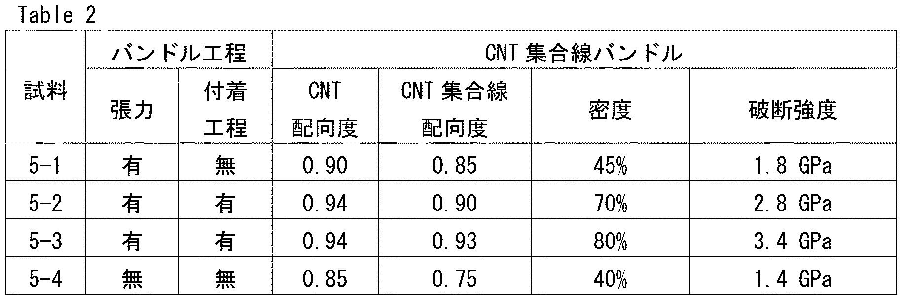
[考察]
試料5-1と試料5-4とを比較すると、バンドル工程においてCNT集合線に張力を加えることにより、CNT集合線バンドルの密度が高くなり、強度が向上することが確認された。
試料5-1と試料5-4とを比較すると、バンドル工程においてCNT集合線に張力を加えることにより、CNT集合線バンドルの密度が高くなり、強度が向上することが確認された。
試料5-1~試料5-3を比較すると、バンドル工程において、揮発性液体の付着工程及び蒸発工程とを行うことにより、CNT集合線バンドルの密度が高くなり、強度が向上することが確認された。
以上のように本開示の実施の形態および実施例について説明を行なったが、上述の各実施の形態および実施例の構成を適宜組み合わせたり、様々に変形することも当初から予定している。
今回開示された実施の形態および実施例はすべての点で例示であって、制限的なものではないと考えられるべきである。本発明の範囲は上記した実施の形態および実施例ではなく請求の範囲によって示され、請求の範囲と均等の意味、および範囲内でのすべての変更が含まれることが意図される。
1,1a,1b,1c,1d カーボンナノチューブ集合線、2 カーボンナノチューブ、3 カーボンナノチューブ集合線バンドル、20,20a,20b,20c CNT集合線製造装置、21 CNT成長部、22 ガス供給部、23 触媒供給部、24,24a カーボンナノチューブ集合部、25 ヒータ、26 触媒保持具、27 触媒、28 電気炉、29 ハニカム構造体、30 CNT伸長部、31 反応管、32 磁力線、33 +電極、34 -電極、35 配向領域、36 不定形領域、37 ミスト発生部、38 ミスト原料液、39 ミスト、40 ガス導入口、41a ホーン振動子、41b 振動子、42 メッシュ43 水、44 空気注入口、45 接続部、47 第1の容器、48 第2の容器、49 容器、50 CNT製造装置、51 バッフル、52 ノズル部、53 配管、55 電線、60,60a,60b,60c ミスト発生装置、500,501 カーボンナノチューブ集合線バンドル製造装置、550 バンドル部、551 液体付着装置、552 巻取装置、553 揮発性液体、554 蒸気、555 絞り、T チューブ部、C コーン部、P 触媒粒子
Claims (37)
- 触媒粒子と、液体状の炭素源とを含むミストを発生させるミスト発生工程と、
前記ミストを加熱することにより、前記触媒粒子からカーボンナノチューブを成長させる成長工程とを備える、カーボンナノチューブの製造方法。 - 前記ミストは、平均粒子径が0.1μm以上50μm以下である、請求項1に記載のカーボンナノチューブの製造方法。
- 前記触媒粒子は、鉄を含む、請求項1又は請求項2に記載のカーボンナノチューブの製造方法。
- 前記ミスト発生工程は、
前記触媒粒子と、前記液体状の炭素源とを含むミスト原料液を準備する準備工程と、
前記ミスト原料液に超音波振動を与えることにより、前記ミスト原料液を霧化する霧化工程と、を含む、請求項1から請求項3のいずれか1項に記載のカーボンナノチューブの製造方法。 - 前記ミスト発生工程は、
前記触媒粒子と、前記液体状の炭素源とを含むミスト原料液を準備する準備工程と、
前記ミスト原料液に超音波振動を与えながら、前記ミスト原料液をメッシュに通過させることにより、前記ミスト原料液を霧化する霧化工程と、を含む、請求項1から請求項3のいずれか1項に記載のカーボンナノチューブの製造方法。 - 前記メッシュは、その開口部の径が1μm以上50μm以下である、請求項5に記載のカーボンナノチューブの製造方法。
- 更に、前記成長工程で得られた前記カーボンナノチューブに引張力を加えることにより、前記カーボンナノチューブを伸長させる伸長工程を備える、請求項1から請求項6のいずれか1項に記載のカーボンナノチューブの製造方法。
- 複数の触媒粒子と、液体状の炭素源とを含むミストを発生させるミスト発生工程と、
前記ミストを加熱することにより、前記複数の触媒粒子のそれぞれから、1又は複数のカーボンナノチューブを成長させる成長工程と、
前記複数のカーボンナノチューブをその長手方向に沿う方向に配向して集合させてカーボンナノチューブ集合線を得る集合工程とを含む、カーボンナノチューブ集合線の製造方法。 - 更に、前記成長工程で得られた前記複数のカーボンナノチューブに引張力を加えることにより、前記複数のカーボンナノチューブを伸長させる伸長工程を備える、請求項8に記載のカーボンナノチューブ集合線の製造方法。
- 前記成長工程において、前記複数のカーボンナノチューブは、第1流路を通過し、
前記集合工程において、前記複数のカーボンナノチューブは、前記第1流路より下流側に配置される1以上の第2流路を通過し、
前記第2流路のそれぞれ断面積は、前記第1流路の断面積よりも小さい、請求項8又は請求項9に記載のカーボンナノチューブ集合線の製造方法。 - 前記第2流路より下流側の雰囲気の温度は、前記第2流路より上流側の前記雰囲気の温度よりも低い、請求項10に記載のカーボンナノチューブ集合線の製造方法。
- 前記第2流路より上流側の前記雰囲気の温度は800℃以上であり、前記第2流路より下流側の前記雰囲気の温度は600℃以下である、請求項10又請求項11に記載のカーボンナノチューブ集合線の製造方法。
- 前記第2流路内の前記雰囲気の温度は、下流側が上流側よりも低く、
前記第2流路内の下流側端部における前記雰囲気の温度は、600℃以下である、請求項11又は請求項12に記載のカーボンナノチューブ集合線の製造方法。 - 前記第2流路内の下流側に、雰囲気の温度が600℃以下である第1領域が存在し、該第1領域の前記第2流路の長手方向に沿う長さは1cm以上である、請求項10から請求項13のいずれか1項に記載のカーボンナノチューブ集合線の製造方法。
- 前記第2流路のそれぞれの断面積は0.01mm2以上4mm2以下である、請求項10から請求項14のいずれか1項に記載のカーボンナノチューブ集合線の製造方法。
- 前記第1流路の断面積S1と、前記第2流路のそれぞれの断面積S2との比S1/S2は100以上1000000以下である、請求項10から請求項15のいずれか1項に記載のカーボンナノチューブ集合線の製造方法。
- 前記集合工程において、前記複数のカーボンナノチューブの径が縮小する、請求項10から請求項16のいずれか1項に記載のカーボンナノチューブ集合線の製造方法。
- 前記第2流路のそれぞれの長さは10mm以上200mm以下である、請求項10から請求項17のいずれか1項に記載のカーボンナノチューブ集合線の製造方法。
- 複数の触媒粒子と、液体状の炭素源とを含むミストを発生させるミスト発生工程と、
前記ミストを加熱することにより、前記複数の触媒粒子のそれぞれから、1又は複数のカーボンナノチューブを成長させる成長工程と、
前記複数のカーボンナノチューブをその長手方向に沿う方向に配向して集合させて複数のカーボンナノチューブ集合線を得る集合工程と、
前記複数のカーボンナノチューブ集合線をその長手方向に沿う方向に配向させて束ねてカーボンナノチューブ集合線バンドルを得るバンドル工程とを含む、カーボンナノチューブ集合線バンドルの製造方法。 - 前記バンドル工程は、前記複数のカーボンナノチューブ集合線に揮発性液体を付着させる付着工程と、前記複数のカーボンナノチューブ集合線に付着させた前記揮発性液体を蒸発させる蒸発工程とを含む、請求項19に記載のカーボンナノチューブ集合線バンドルの製造方法。
- 前記付着工程は、前記複数のカーボンナノチューブ集合線をこれらの長手方向に沿う方向に配向して束ねる前に行われる、請求項20に記載のカーボンナノチューブ集合線バンドルの製造方法。
- 前記付着工程は、前記複数のカーボンナノチューブ集合線をこれらの長手方向に沿う方向に配向して束ねた後に行われる、請求項20に記載のカーボンナノチューブ集合線バンドルの製造方法。
- 前記バンドル工程は、前記複数のカーボンナノチューブ集合線に張力を加えながら行われる、請求項19から請求項22のいずれか1項に記載のカーボンナノチューブ集合線バンドルの製造方法。
- 触媒粒子と、液体状の炭素源とを含むミストを発生させるミスト発生部と、
前記ミスト発生部と接続され、前記ミストを加熱することにより、前記触媒粒子からカーボンナノチューブを成長させる、管状のカーボンナノチューブ成長部と、を備える、カーボンナノチューブ製造装置。 - 前記ミスト発生部は、振動子を有し、
前記振動子は、前記触媒粒子と、前記液体状の炭素源とを含むミスト原料液に超音波振動を与えることにより、前記ミスト原料液を霧化して前記ミストを発生させる、請求項24に記載のカーボンナノチューブ製造装置。 - 前記ミスト発生部は、振動子と、前記振動子の振動面に対向して配置されたメッシュとを有し、
前記振動子は、前記振動面と前記メッシュとの間に供給された前記触媒粒子と、前記液体状の炭素源とを含むミスト原料液に超音波振動を与えながら、前記ミスト原料液を前記メッシュに通過させることにより霧化して前記ミストを発生させる、請求項24に記載のカーボンナノチューブ製造装置。 - 前記メッシュは、その開口部の径が1μm以上50μm以下である、請求項26に記載のカーボンナノチューブ製造装置。
- 複数の触媒粒子と、液体状の炭素源とを含むミストを発生させるミスト発生部と、
前記ミスト発生部と接続され、前記ミストを加熱することにより、前記複数の触媒粒子のそれぞれから、1又は複数のカーボンナノチューブを成長させる、管状のカーボンナノチューブ成長部と、
前記カーボンナノチューブ成長部の一方の端部側に配置され、前記カーボンナノチューブ成長部で得られた複数のカーボンナノチューブをその長手方向に沿う方向に配向して集合させてカーボンナノチューブ集合線を得るカーボンナノチューブ集合部と、を備える、カーボンナノチューブ集合線製造装置。 - 前記カーボンナノチューブ成長部は、その内部に第1流路を有し、
前記カーボンナノチューブ集合部は、その内部に1以上の第2流路を有し、
前記第2流路のそれぞれの断面積は、前記第1流路の断面積よりも小さい、請求項28に記載のカーボンナノチューブ集合線製造装置。 - 前記カーボンナノチューブ集合部はハニカム構造を有する、請求項28又は請求項29に記載のカーボンナノチューブ集合線製造装置。
- 前記ハニカム構造は、複数の貫通孔から構成される複数の第2流路を有するハニカム構造体であり、
前記第2流路のそれぞれの断面積は0.01mm2以上4mm2以下である、請求項30に記載のカーボンナノチューブ集合線製造装置。 - 前記第1流路の断面積S1と、前記第2流路のそれぞれの断面積S2との比S1/S2は100以上1000000以下である、請求項29から請求項31のいずれか1項に記載のカーボンナノチューブ集合線製造装置。
- 前記カーボンナノチューブ集合部において、前記複数のカーボンナノチューブの径が縮小する、請求項28から請求項32のいずれか1項に記載のカーボンナノチューブ集合線製造装置。
- 前記カーボンナノチューブ集合部の第2流路のそれぞれの長さは10mm以上200mm以下である、請求項29から請求項33のいずれか1項に記載のカーボンナノチューブ集合線製造装置。
- 請求項28から請求項34のいずれか1項に記載のカーボンナノチューブ集合線製造装置と、
前記カーボンナノチューブ集合線製造装置により得られた複数のカーボンナノチューブ集合線をその長手方向に沿う方向に配向して束ねてカーボンナノチューブ集合線バンドルを得るバンドル部とを備える、カーボンナノチューブ集合線バンドル製造装置。 - 前記バンドル部は、前記複数のカーボンナノチューブ集合線に揮発性液体を付着させる液体付着装置を含む、請求項35に記載のカーボンナノチューブ集合線バンドル製造装置。
- 前記バンドル部は、前記複数のカーボンナノチューブ集合線に張力を加えながら、前記複数のカーボンナノチューブ集合線をその長手方向に沿う方向に配向して束ねて巻き取る巻取装置を含む、請求項35又は請求項36に記載のカーボンナノチューブ集合線バンドル製造装置。
Priority Applications (3)
| Application Number | Priority Date | Filing Date | Title |
|---|---|---|---|
| JP2021502009A JP7455805B2 (ja) | 2019-02-22 | 2020-02-18 | カーボンナノチューブの製造方法、カーボンナノチューブ集合線の製造方法、カーボンナノチューブ集合線バンドルの製造方法、カーボンナノチューブ製造装置、カーボンナノチューブ集合線製造装置及びカーボンナノチューブ集合線バンドル製造装置 |
| US17/433,019 US11866330B2 (en) | 2019-02-22 | 2020-02-18 | Method for manufacturing carbon nanotube, method for manufacturing carbon nanotube assembled wire, method for manufacturing carbon nanotube assembled wire bundle, carbon nanotube manufacturing apparatus, carbon nanotube assembled wire manufacturing apparatus, and carbon nanotube assembled wire bundle manufacturing apparatus |
| CN202080015114.7A CN113490638B (zh) | 2019-02-22 | 2020-02-18 | 碳纳米管及其集合线、集合线集束的制法、它们的制造装置 |
Applications Claiming Priority (4)
| Application Number | Priority Date | Filing Date | Title |
|---|---|---|---|
| JP2019030644 | 2019-02-22 | ||
| JP2019-030644 | 2019-02-22 | ||
| JP2019160766 | 2019-09-03 | ||
| JP2019-160766 | 2019-09-03 |
Publications (1)
| Publication Number | Publication Date |
|---|---|
| WO2020171047A1 true WO2020171047A1 (ja) | 2020-08-27 |
Family
ID=72144283
Family Applications (1)
| Application Number | Title | Priority Date | Filing Date |
|---|---|---|---|
| PCT/JP2020/006205 Ceased WO2020171047A1 (ja) | 2019-02-22 | 2020-02-18 | カーボンナノチューブの製造方法、カーボンナノチューブ集合線の製造方法、カーボンナノチューブ集合線バンドルの製造方法、カーボンナノチューブ製造装置、カーボンナノチューブ集合線製造装置及びカーボンナノチューブ集合線バンドル製造装置 |
Country Status (4)
| Country | Link |
|---|---|
| US (1) | US11866330B2 (ja) |
| JP (1) | JP7455805B2 (ja) |
| CN (1) | CN113490638B (ja) |
| WO (1) | WO2020171047A1 (ja) |
Cited By (7)
| Publication number | Priority date | Publication date | Assignee | Title |
|---|---|---|---|---|
| GB2602379A (en) * | 2020-10-15 | 2022-06-29 | Q Flo Ltd | Method |
| JPWO2022181692A1 (ja) * | 2021-02-25 | 2022-09-01 | ||
| WO2023026950A1 (ja) * | 2021-08-25 | 2023-03-02 | 住友電気工業株式会社 | カーボンナノチューブ集合線の製造方法及びカーボンナノチューブ集合線製造装置 |
| WO2024263015A1 (ko) * | 2023-06-21 | 2024-12-26 | 주식회사 제이오 | 고전도성 탄소나노튜브의 제조 방법 |
| WO2025013504A1 (ja) * | 2023-07-07 | 2025-01-16 | 住友化学株式会社 | 多層カーボンナノチューブ集合体、多層カーボンナノチューブ分散液、導電材料、電極、二次電池、平面状集合体、フィルター、電磁波シールド及び極端紫外線用ペリクル |
| WO2025033196A1 (ja) * | 2023-08-04 | 2025-02-13 | 富士通商株式会社 | 積層コンデンサ用電極とその製造方法 |
| WO2025248851A1 (ja) * | 2024-05-29 | 2025-12-04 | 住友電気工業株式会社 | カーボンナノチューブ複合体、集合線、カーボンナノチューブ複合体の製造方法、カーボンナノチューブ複合体の製造装置、およびカーボンナノチューブ複合体製造用鉄系触媒 |
Citations (3)
| Publication number | Priority date | Publication date | Assignee | Title |
|---|---|---|---|---|
| JPS5819888B2 (ja) * | 1977-08-12 | 1983-04-20 | 本田技研工業株式会社 | デイスクブレ−キ装置 |
| WO2016208558A1 (ja) * | 2015-06-25 | 2016-12-29 | 国立大学法人静岡大学 | カーボンナノチューブの製造方法、カーボンナノチューブフォレスト、紡績源部材、構造体および複合構造体 |
| JP2018505121A (ja) * | 2014-12-05 | 2018-02-22 | キュー‐フロ リミテッド | 方法 |
Family Cites Families (28)
| Publication number | Priority date | Publication date | Assignee | Title |
|---|---|---|---|---|
| CN1176014C (zh) * | 2002-02-22 | 2004-11-17 | 清华大学 | 一种直接合成超长连续单壁碳纳米管的工艺方法 |
| EP1548057A4 (en) * | 2002-09-30 | 2006-02-15 | Bridgestone Corp | CARBON-ORIENTED NANOTUBE COMPOSITE, PROCESS FOR PRODUCTION OF ORIENTED CARBON NANOTUBE COMPOSITE AND PRODUCT USING CARBON NANOTUBE COMPOSITE ORIENTED, PNEUMATIC, VEHICLE WHEEL, WHEEL AND PNEUMATIC ASSEMBLY, AND DISC BRAKE |
| GB0316367D0 (en) * | 2003-07-11 | 2003-08-13 | Univ Cambridge Tech | Production of agglomerates from gas phase |
| WO2005098084A2 (en) * | 2004-01-15 | 2005-10-20 | Nanocomp Technologies, Inc. | Systems and methods for synthesis of extended length nanostructures |
| JP4379247B2 (ja) | 2004-04-23 | 2009-12-09 | 住友電気工業株式会社 | カーボンナノ構造体の製造方法 |
| JP4604563B2 (ja) * | 2004-06-08 | 2011-01-05 | 住友電気工業株式会社 | カーボンナノ構造体の製造方法 |
| US8372470B2 (en) * | 2005-10-25 | 2013-02-12 | Massachusetts Institute Of Technology | Apparatus and methods for controlled growth and assembly of nanostructures |
| JP5046078B2 (ja) * | 2006-03-14 | 2012-10-10 | 独立行政法人産業技術総合研究所 | 単層のカーボンナノチューブの製造方法 |
| JP2008201648A (ja) | 2007-02-22 | 2008-09-04 | Mitsubishi Electric Corp | カーボンナノチューブの製造装置およびカーボンナノチューブの製造方法 |
| JP5282043B2 (ja) * | 2008-01-21 | 2013-09-04 | 日機装株式会社 | カーボンナノチューブ製造装置 |
| JP4926148B2 (ja) * | 2008-10-02 | 2012-05-09 | 豊田合成株式会社 | 断熱オイルパン構造 |
| JP2010099572A (ja) * | 2008-10-22 | 2010-05-06 | Sumitomo Electric Ind Ltd | 触媒基材およびこれを用いたカーボンナノ構造体の製造方法 |
| JP5672008B2 (ja) * | 2009-01-20 | 2015-02-18 | 日本電気株式会社 | ナノカーボン複合体の製造方法および製造装置 |
| US20110135835A1 (en) | 2009-06-08 | 2011-06-09 | Massachusetts Institute Of Technology | Method for depositing a carbon nanotube thin film coating on an arbitrary substrate directly from chemical vapor deposition synthesis |
| US8883260B2 (en) * | 2009-06-17 | 2014-11-11 | National Institute Of Advanced Industrial Science And Technology | Apparatus and method for producing carbon |
| EP2444370A4 (en) * | 2009-06-17 | 2015-04-29 | Nat Inst Of Advanced Ind Scien | METHOD FOR PRODUCING A CARBON NANOTUBE ASSEMBLY WITH A LARGE SPECIFIC SURFACE AREA |
| JP2011148689A (ja) | 2009-12-25 | 2011-08-04 | Mefs Kk | カーボンナノチューブから成る集合体および糸条体の製造方法 |
| JP5699387B2 (ja) * | 2010-03-29 | 2015-04-08 | 地方独立行政法人大阪府立産業技術総合研究所 | カーボンナノチューブ撚糸およびその製造方法 |
| GB2485339B (en) * | 2010-11-02 | 2018-10-03 | Cambridge Entpr Ltd | Method of making carbon nanotubes |
| CN103435029A (zh) * | 2013-09-05 | 2013-12-11 | 武汉博力信纳米科技有限公司 | 超声雾化辅助制备连续碳纳米管聚集体的装置及方法 |
| CN105329842B (zh) * | 2014-06-18 | 2017-06-06 | 清华大学 | 碳纳米管阵列的转移方法及碳纳米管结构的制备方法 |
| CN104117461B (zh) | 2014-08-12 | 2016-04-13 | 中国科学技术大学 | 一种基于毛细现象的超声雾化装置 |
| CN104891472A (zh) * | 2015-05-11 | 2015-09-09 | 南昌大学 | 一种直线型碳纳米管的合成方法 |
| US9878912B2 (en) * | 2015-10-07 | 2018-01-30 | King Fahd University Of Petroleum And Minerals | Method for preparing multi-wall carbon nanotubes using chemical vapor deposition with an atomization system |
| KR101990610B1 (ko) | 2015-12-03 | 2019-06-18 | 주식회사 엘지화학 | 탄소나노튜브 섬유화 장치 |
| WO2017128944A1 (zh) | 2016-01-29 | 2017-08-03 | 中国科学院苏州纳米技术与纳米仿生研究所 | 碳纳米管聚集体于制备纳米碳抗冲击材料中的用途及其制备方法 |
| CN106395791A (zh) * | 2016-08-26 | 2017-02-15 | 宁波埃飞化工科技有限公司 | 一种碳纳米管的喷雾式窑炉及其生产方法 |
| EP3579249B1 (en) | 2017-02-03 | 2024-04-10 | Furukawa Electric Co., Ltd. | Carbon nanotube wire, method for manufacturing carbon nanotube, and method for manufacturing carbon nanotube wire |
-
2020
- 2020-02-18 WO PCT/JP2020/006205 patent/WO2020171047A1/ja not_active Ceased
- 2020-02-18 US US17/433,019 patent/US11866330B2/en active Active
- 2020-02-18 CN CN202080015114.7A patent/CN113490638B/zh active Active
- 2020-02-18 JP JP2021502009A patent/JP7455805B2/ja active Active
Patent Citations (3)
| Publication number | Priority date | Publication date | Assignee | Title |
|---|---|---|---|---|
| JPS5819888B2 (ja) * | 1977-08-12 | 1983-04-20 | 本田技研工業株式会社 | デイスクブレ−キ装置 |
| JP2018505121A (ja) * | 2014-12-05 | 2018-02-22 | キュー‐フロ リミテッド | 方法 |
| WO2016208558A1 (ja) * | 2015-06-25 | 2016-12-29 | 国立大学法人静岡大学 | カーボンナノチューブの製造方法、カーボンナノチューブフォレスト、紡績源部材、構造体および複合構造体 |
Cited By (13)
| Publication number | Priority date | Publication date | Assignee | Title |
|---|---|---|---|---|
| GB2602379A (en) * | 2020-10-15 | 2022-06-29 | Q Flo Ltd | Method |
| GB2602379B (en) * | 2020-10-15 | 2025-04-09 | Q Flo Ltd | Producing carbon nanotube structures by floating catalyst CVD with an electrical field |
| US20240308853A1 (en) * | 2021-02-25 | 2024-09-19 | Sumitomo Electric Industries, Ltd. | Method and apparatus for manufacturing carbon nanotube assembled wire |
| JPWO2022181692A1 (ja) * | 2021-02-25 | 2022-09-01 | ||
| WO2022181692A1 (ja) * | 2021-02-25 | 2022-09-01 | 住友電気工業株式会社 | カーボンナノチューブ集合線の製造方法及びカーボンナノチューブ集合線製造装置 |
| CN116888068A (zh) * | 2021-02-25 | 2023-10-13 | 住友电气工业株式会社 | 碳纳米管集合线的制造方法和碳纳米管集合线制造装置 |
| WO2023026950A1 (ja) * | 2021-08-25 | 2023-03-02 | 住友電気工業株式会社 | カーボンナノチューブ集合線の製造方法及びカーボンナノチューブ集合線製造装置 |
| JPWO2023026950A1 (ja) * | 2021-08-25 | 2023-03-02 | ||
| JP7834106B2 (ja) | 2021-08-25 | 2026-03-23 | 住友電気工業株式会社 | カーボンナノチューブ集合線の製造方法及びカーボンナノチューブ集合線製造装置 |
| WO2024263015A1 (ko) * | 2023-06-21 | 2024-12-26 | 주식회사 제이오 | 고전도성 탄소나노튜브의 제조 방법 |
| WO2025013504A1 (ja) * | 2023-07-07 | 2025-01-16 | 住友化学株式会社 | 多層カーボンナノチューブ集合体、多層カーボンナノチューブ分散液、導電材料、電極、二次電池、平面状集合体、フィルター、電磁波シールド及び極端紫外線用ペリクル |
| WO2025033196A1 (ja) * | 2023-08-04 | 2025-02-13 | 富士通商株式会社 | 積層コンデンサ用電極とその製造方法 |
| WO2025248851A1 (ja) * | 2024-05-29 | 2025-12-04 | 住友電気工業株式会社 | カーボンナノチューブ複合体、集合線、カーボンナノチューブ複合体の製造方法、カーボンナノチューブ複合体の製造装置、およびカーボンナノチューブ複合体製造用鉄系触媒 |
Also Published As
| Publication number | Publication date |
|---|---|
| JP7455805B2 (ja) | 2024-03-26 |
| JPWO2020171047A1 (ja) | 2021-12-23 |
| US20220153585A1 (en) | 2022-05-19 |
| CN113490638A (zh) | 2021-10-08 |
| CN113490638B (zh) | 2024-03-29 |
| US11866330B2 (en) | 2024-01-09 |
Similar Documents
| Publication | Publication Date | Title |
|---|---|---|
| JP7455805B2 (ja) | カーボンナノチューブの製造方法、カーボンナノチューブ集合線の製造方法、カーボンナノチューブ集合線バンドルの製造方法、カーボンナノチューブ製造装置、カーボンナノチューブ集合線製造装置及びカーボンナノチューブ集合線バンドル製造装置 | |
| JP7640266B2 (ja) | カーボンナノチューブ集合線、カーボンナノチューブ集合線バンドル及びカーボンナノチューブ構造体 | |
| JP7441799B2 (ja) | カーボンナノチューブの製造方法、カーボンナノチューブ集合線の製造方法、カーボンナノチューブ集合線バンドルの製造方法、カーボンナノチューブ製造装置、カーボンナノチューブ集合線製造装置及びカーボンナノチューブ集合線バンドル製造装置 | |
| CN102001641B (zh) | 碳纳米管线状结构的制备方法 | |
| US7754283B2 (en) | Continuous production of carbon nanotubes | |
| TWI312337B (en) | Method for making the carbon nanotubes silk | |
| US20110189459A1 (en) | Fibrous columnar structure aggregate and pressure-sensitive adhesive member using the aggregate | |
| US12480230B2 (en) | Carbon nanotube-resin composite and method for manufacturing carbon nanotube-resin composite | |
| Kiselev et al. | Carbon micro-and nanotubes synthesized by PE-CVD technique: Tube structure and catalytic particles crystallography | |
| US20240367978A1 (en) | Method and apparatus for manufacturing carbon nanotube assembled wire | |
| US6979433B1 (en) | Synthesis of multi-wall carbon nanotubes using unseeded hydrocarbon diffusion flames | |
| CN111094179A (zh) | 由排列碳纳米管制成的电缆的制造方法 | |
| US20240308853A1 (en) | Method and apparatus for manufacturing carbon nanotube assembled wire | |
| WO2023026951A1 (ja) | カーボンナノチューブ集合線の製造方法及びカーボンナノチューブ集合線製造装置 | |
| US12221347B2 (en) | Carbon nanotube assembled wire and carbon nanotube assembled wire bundle | |
| TWI391323B (zh) | 奈米碳管線狀結構的製備方法 | |
| Gargate et al. | In situ synthesis of carbon nanotubes on heated scanning probes using dip pen techniques | |
| García-Betancourt et al. | Pine-tree-like morphologies of nitrogen-doped carbon nanotubes: Electron field emission enhancement | |
| Kennedy | Carbon Nanotubes, Synthesis, Growth and Orientation Control |
Legal Events
| Date | Code | Title | Description |
|---|---|---|---|
| 121 | Ep: the epo has been informed by wipo that ep was designated in this application |
Ref document number: 20760279 Country of ref document: EP Kind code of ref document: A1 |
|
| ENP | Entry into the national phase |
Ref document number: 2021502009 Country of ref document: JP Kind code of ref document: A |
|
| NENP | Non-entry into the national phase |
Ref country code: DE |
|
| 122 | Ep: pct application non-entry in european phase |
Ref document number: 20760279 Country of ref document: EP Kind code of ref document: A1 |