WO2020171012A1 - 内視鏡システム - Google Patents
内視鏡システム Download PDFInfo
- Publication number
- WO2020171012A1 WO2020171012A1 PCT/JP2020/006020 JP2020006020W WO2020171012A1 WO 2020171012 A1 WO2020171012 A1 WO 2020171012A1 JP 2020006020 W JP2020006020 W JP 2020006020W WO 2020171012 A1 WO2020171012 A1 WO 2020171012A1
- Authority
- WO
- WIPO (PCT)
- Prior art keywords
- light
- switching timing
- brightness
- illumination light
- illumination
- Prior art date
- Legal status (The legal status is an assumption and is not a legal conclusion. Google has not performed a legal analysis and makes no representation as to the accuracy of the status listed.)
- Ceased
Links
Images







Classifications
-
- A—HUMAN NECESSITIES
- A61—MEDICAL OR VETERINARY SCIENCE; HYGIENE
- A61B—DIAGNOSIS; SURGERY; IDENTIFICATION
- A61B1/00—Instruments for performing medical examinations of the interior of cavities or tubes of the body by visual or photographical inspection, e.g. endoscopes; Illuminating arrangements therefor
- A61B1/06—Instruments for performing medical examinations of the interior of cavities or tubes of the body by visual or photographical inspection, e.g. endoscopes; Illuminating arrangements therefor with illuminating arrangements
- A61B1/0638—Instruments for performing medical examinations of the interior of cavities or tubes of the body by visual or photographical inspection, e.g. endoscopes; Illuminating arrangements therefor with illuminating arrangements providing two or more wavelengths
-
- A—HUMAN NECESSITIES
- A61—MEDICAL OR VETERINARY SCIENCE; HYGIENE
- A61B—DIAGNOSIS; SURGERY; IDENTIFICATION
- A61B1/00—Instruments for performing medical examinations of the interior of cavities or tubes of the body by visual or photographical inspection, e.g. endoscopes; Illuminating arrangements therefor
- A61B1/00002—Operational features of endoscopes
- A61B1/00004—Operational features of endoscopes characterised by electronic signal processing
- A61B1/00006—Operational features of endoscopes characterised by electronic signal processing of control signals
-
- A—HUMAN NECESSITIES
- A61—MEDICAL OR VETERINARY SCIENCE; HYGIENE
- A61B—DIAGNOSIS; SURGERY; IDENTIFICATION
- A61B1/00—Instruments for performing medical examinations of the interior of cavities or tubes of the body by visual or photographical inspection, e.g. endoscopes; Illuminating arrangements therefor
- A61B1/00002—Operational features of endoscopes
- A61B1/00004—Operational features of endoscopes characterised by electronic signal processing
- A61B1/00009—Operational features of endoscopes characterised by electronic signal processing of image signals during a use of endoscope
- A61B1/000094—Operational features of endoscopes characterised by electronic signal processing of image signals during a use of endoscope extracting biological structures
-
- A—HUMAN NECESSITIES
- A61—MEDICAL OR VETERINARY SCIENCE; HYGIENE
- A61B—DIAGNOSIS; SURGERY; IDENTIFICATION
- A61B1/00—Instruments for performing medical examinations of the interior of cavities or tubes of the body by visual or photographical inspection, e.g. endoscopes; Illuminating arrangements therefor
- A61B1/06—Instruments for performing medical examinations of the interior of cavities or tubes of the body by visual or photographical inspection, e.g. endoscopes; Illuminating arrangements therefor with illuminating arrangements
- A61B1/0655—Control therefor
-
- A—HUMAN NECESSITIES
- A61—MEDICAL OR VETERINARY SCIENCE; HYGIENE
- A61B—DIAGNOSIS; SURGERY; IDENTIFICATION
- A61B1/00—Instruments for performing medical examinations of the interior of cavities or tubes of the body by visual or photographical inspection, e.g. endoscopes; Illuminating arrangements therefor
- A61B1/06—Instruments for performing medical examinations of the interior of cavities or tubes of the body by visual or photographical inspection, e.g. endoscopes; Illuminating arrangements therefor with illuminating arrangements
- A61B1/0661—Endoscope light sources
- A61B1/0684—Endoscope light sources using light emitting diodes [LED]
-
- G—PHYSICS
- G02—OPTICS
- G02B—OPTICAL ELEMENTS, SYSTEMS OR APPARATUS
- G02B23/00—Telescopes, e.g. binoculars; Periscopes; Instruments for viewing the inside of hollow bodies; Viewfinders; Optical aiming or sighting devices
- G02B23/24—Instruments or systems for viewing the inside of hollow bodies, e.g. fibrescopes
-
- G—PHYSICS
- G02—OPTICS
- G02B—OPTICAL ELEMENTS, SYSTEMS OR APPARATUS
- G02B23/00—Telescopes, e.g. binoculars; Periscopes; Instruments for viewing the inside of hollow bodies; Viewfinders; Optical aiming or sighting devices
- G02B23/24—Instruments or systems for viewing the inside of hollow bodies, e.g. fibrescopes
- G02B23/26—Instruments or systems for viewing the inside of hollow bodies, e.g. fibrescopes using light guides
-
- A—HUMAN NECESSITIES
- A61—MEDICAL OR VETERINARY SCIENCE; HYGIENE
- A61B—DIAGNOSIS; SURGERY; IDENTIFICATION
- A61B1/00—Instruments for performing medical examinations of the interior of cavities or tubes of the body by visual or photographical inspection, e.g. endoscopes; Illuminating arrangements therefor
- A61B1/00163—Optical arrangements
- A61B1/00186—Optical arrangements with imaging filters
-
- A—HUMAN NECESSITIES
- A61—MEDICAL OR VETERINARY SCIENCE; HYGIENE
- A61B—DIAGNOSIS; SURGERY; IDENTIFICATION
- A61B1/00—Instruments for performing medical examinations of the interior of cavities or tubes of the body by visual or photographical inspection, e.g. endoscopes; Illuminating arrangements therefor
- A61B1/04—Instruments for performing medical examinations of the interior of cavities or tubes of the body by visual or photographical inspection, e.g. endoscopes; Illuminating arrangements therefor combined with photographic or television appliances
- A61B1/043—Instruments for performing medical examinations of the interior of cavities or tubes of the body by visual or photographical inspection, e.g. endoscopes; Illuminating arrangements therefor combined with photographic or television appliances for fluorescence imaging
-
- A—HUMAN NECESSITIES
- A61—MEDICAL OR VETERINARY SCIENCE; HYGIENE
- A61B—DIAGNOSIS; SURGERY; IDENTIFICATION
- A61B1/00—Instruments for performing medical examinations of the interior of cavities or tubes of the body by visual or photographical inspection, e.g. endoscopes; Illuminating arrangements therefor
- A61B1/04—Instruments for performing medical examinations of the interior of cavities or tubes of the body by visual or photographical inspection, e.g. endoscopes; Illuminating arrangements therefor combined with photographic or television appliances
- A61B1/045—Control thereof
-
- A—HUMAN NECESSITIES
- A61—MEDICAL OR VETERINARY SCIENCE; HYGIENE
- A61B—DIAGNOSIS; SURGERY; IDENTIFICATION
- A61B1/00—Instruments for performing medical examinations of the interior of cavities or tubes of the body by visual or photographical inspection, e.g. endoscopes; Illuminating arrangements therefor
- A61B1/04—Instruments for performing medical examinations of the interior of cavities or tubes of the body by visual or photographical inspection, e.g. endoscopes; Illuminating arrangements therefor combined with photographic or television appliances
- A61B1/05—Instruments for performing medical examinations of the interior of cavities or tubes of the body by visual or photographical inspection, e.g. endoscopes; Illuminating arrangements therefor combined with photographic or television appliances characterised by the image sensor, e.g. camera, being in the distal end portion
-
- A—HUMAN NECESSITIES
- A61—MEDICAL OR VETERINARY SCIENCE; HYGIENE
- A61B—DIAGNOSIS; SURGERY; IDENTIFICATION
- A61B1/00—Instruments for performing medical examinations of the interior of cavities or tubes of the body by visual or photographical inspection, e.g. endoscopes; Illuminating arrangements therefor
- A61B1/06—Instruments for performing medical examinations of the interior of cavities or tubes of the body by visual or photographical inspection, e.g. endoscopes; Illuminating arrangements therefor with illuminating arrangements
- A61B1/07—Instruments for performing medical examinations of the interior of cavities or tubes of the body by visual or photographical inspection, e.g. endoscopes; Illuminating arrangements therefor with illuminating arrangements using light-conductive means, e.g. optical fibres
Definitions
- the present invention relates to an endoscope system that switches and displays a plurality of types of images.
- an endoscope system including a light source device, an endoscope, and a processor device is widely used.
- the observation target is irradiated with illumination light from the endoscope, and the observation target is illuminated by the illumination light based on an RGB image signal obtained by imaging the observation target with an imaging device of the endoscope. The image of is displayed on the monitor.
- an observation target is illuminated with a plurality of illumination lights having different wavelength ranges, depending on the purpose of diagnosis.
- two blue narrow band lights that is, NB1 light having a peak wavelength of 422 nm and NB2 light having a peak wavelength of 460 to 470 nm are alternately illuminated, thereby observing the inside of the blood vessel included in the observation target.
- NB1 light having a peak wavelength of 422 nm and NB2 light having a peak wavelength of 460 to 470 nm are alternately illuminated, thereby observing the inside of the blood vessel included in the observation target.
- Obtaining oxygen saturation is described.
- light having a peak in the B1 region first B region: 390 nm to 440 nm
- light having a peak in the B2 region second B region: 440 nm to 490 nm
- the resolution information of the superficial blood vessels is obtained by illuminating and imaging with an image sensor including B pixels that are sensitive to both the light in the B1 region and the light in the B2 region.
- the desired tissue information of the biological tissue is suitable for diagnosis by using violet light having a central wavelength of 405 nm, blue laser light having a central wavelength of 445 nm, and excitation light emission excited by blue laser light. It is described that acquisition is made in a clear state.
- shortwave light having a depth of penetration to the surface layer and medium wavelength light having a depth of penetration to the deep layer are switched and illuminated.
- a surface image obtained by illuminating light and a deep image obtained by illuminating medium wavelength light are switched and displayed.
- the amount of light of each wavelength needs to be appropriately controlled according to the brightness of the subject.
- the spectral reflectance differs from that of a standard subject due to changes in the observed region, individual differences, presence of diseases such as inflammation, or changes in the subject such as the presence or absence of pigment dispersion, and each image taken with multiple wavelengths of light If there is a large difference in brightness, color tone, or the like, and if the difference from the target brightness is large when the light of each wavelength is switched, the light amount of each wavelength of light may not correspond to the brightness of the subject.
- An object of the present invention is to provide an endoscope system capable of controlling the amount of illumination light of each light according to the change of the subject when switching and illuminating a plurality of lights.
- An endoscope system of the present invention includes a light source unit that emits first illumination light and second illumination light having an emission spectrum different from that of the first illumination light, a first processor, and a second processor.
- the first processor emits the second illumination light and the light emission period K(N) in which the first illumination light is emitted when performing the control of automatically switching between the first illumination light and the second illumination light to emit light.
- the light emission period L(N) is a light emission period of at least one frame or more, and the second processor images the subject illuminated by the first illumination light in the light emission period K(N) of the first illumination light.
- the image signal group is acquired, the first brightness D1 of the object is calculated from the first image signal, the second brightness D2 of the object is calculated from the second image signal, and the first brightness or the second brightness is calculated.
- the second processor sets at the first switching timing T1 of the light emitting period L(N) using the information regarding the first switching timing T1 of the light emitting period L(N-2) before the light emitting period L(N).
- the light amount of the second illumination light is adjusted, or the information about the second switching timing T2 of the light emission period K(N ⁇ 2) before the light emission period K(N) is used to determine the light emission period K(N). It is preferable to perform at least one of adjusting the light amount of the first illumination light set at the second switching timing T2.
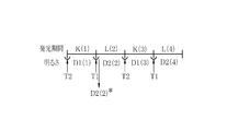
- the information regarding the first switching timing T1 of the light emitting period L(2) is set as the target. It is preferable that the adjustment amount X(2) obtained by dividing the brightness by the second brightness D2(2) * at the first switching timing T1 is multiplied by the light amount of the second illumination light.
- the second processor uses the information about the first switching timing T1 of the plurality of light emitting periods L(N-P) prior to the light emitting period L(N) at the first switching timing T1 of the light emitting period L(N).
- the light emission period K(N) is adjusted by adjusting the set light amount of the second illumination light or using information on the second switching timing T2 of the light emission period K(NP) prior to the light emission period K(N). It is preferable to perform at least one of adjusting the light amount of the first illumination light set at the second switching timing T2.
- the second brightness D2 of the first switching timing T1 includes a plurality of second brightness D2(NP) indicating the second brightness of the first switching timing T1 of the plurality of light emitting periods L(NP).
- the second processor adjusts the light amount of the second illumination light set at the first switching timing T1 of the light emission period L(N), the second processor of the plurality of light emission periods L(N ⁇ P).
- the specific adjustment coefficient X obtained by dividing the target brightness by a value obtained by multiplying each of the plurality of second brightness D2(NP) by a weighting coefficient and adding the target brightness is used as the information on the 1 switch timing T1.
- the light amount of the second illumination light is preferably multiplied.
- the second processor sets at the first switching timing T1 of the light emitting period L(N) using the information regarding the second switching timing T2 of the light emitting period K(N-1) before the light emitting period L(N).
- the light amount of the second illumination light is adjusted, or the information about the first switching timing T1 of the light emission period L(N ⁇ 1) before the light emission period K(N) is used to determine the first light emission period K(N). It is preferable to perform at least one of adjusting the light amount of the first illumination light set at the second switching timing T2.
- the light emission is performed as the information regarding the second switching timing T2 in the light emitting period K(3).
- the first brightness D1(3) * at the second switching timing is divided by the target brightness, and the adjustment coefficient Y(3) obtained is multiplied by the light amount of the second illumination light. It is preferable to carry out.
- the second processor has information regarding the second switching timing T2 of the plurality of light emitting periods K(NQ) prior to the light emitting period L(N) and the first switching timing T1 of the plurality of light emitting periods L(NP). Is used to adjust the light amount of the second illumination light set at the first switching timing T1 of the light emission period L(N), or a plurality of light emission periods L(N ⁇ Q) earlier than the light emission period K(N) are adjusted. ) Of the first illuminating light set at the second switching timing T2 of the light emitting period K(N) by using the information on the first switching timing T1 of the above) and the second switching timing T2 of the plurality of light emitting periods K(NP). It is preferable to perform at least one of adjusting the light amount.
- the second processor adjusts the light amount of the second illumination light set at the first switching timing T1 in the light emission period L(6), the second switching timing in the light emission period K(5).
- a specific adjustment coefficient based on the first brightness D1(5) * of T2, the second brightness D2(4) * of the first switching timing T1 of the light emission period L(4), and the preset target brightness V It is preferable that Y is multiplied by the light amount of the second illumination light.
- the first brightness or the second brightness is preferably obtained based on an average of pixel values other than blood vessels or lesions in the first image signal or the second image signal.
- the first brightness or the second brightness is an average of pixel values other than abnormal pixels including at least one of a dark part and halation in the first image signal or the second image signal, or the first image signal group or the second image signal. It is preferable to obtain the average value of the pixel values of the normal image signals other than the first image signal or the second image signal including the abnormal pixels in the image signal group.
- the second processor adjusts the light amount of the second illumination light or adjusts the light amount of the first illumination light only when the first brightness or the second brightness is within a predetermined target brightness range. Is preferably performed.
- the light amount of each illumination light can be controlled according to the change of the subject.
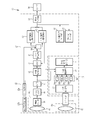
- the endoscope system 10 includes an endoscope 12, a light source device 14, a processor device 16, a monitor 18 (display unit), and a user interface 19.
- the endoscope 12 is optically connected to the light source device 14 and electrically connected to the processor device 16.
- the endoscope 12 includes an insertion portion 12a to be inserted into a subject, an operation portion 12b provided at a proximal end portion of the insertion portion 12a, a bending portion 12c and a distal end portion 12d provided at a distal end side of the insertion portion 12a. have.
- the bending portion 12c is bent by operating the angle knob 12e of the operation portion 12b. With this bending operation, the tip portion 12d is directed in a desired direction.
- the user interface 19 includes a mouse in addition to the illustrated keyboard.
- the operation unit 12b is provided with a mode switching SW 13a and a still image acquisition instruction unit 13b.
- the mode switching SW 13a is used for switching operation among the normal light observation mode, the first special light observation mode, the second special light observation mode, and the multi observation mode.
- the normal light observation mode is a mode in which a normal image is displayed on the monitor 18.
- the first special light observation mode is a mode in which a first special observation image in which surface layer information such as surface blood vessels is emphasized is displayed on the monitor 18.
- the second special light observation mode is a mode in which a second special observation image in which deep information such as deep blood vessels is emphasized is displayed on the monitor 18.
- the multi-observation mode is a mode in which the first special observation image (hereinafter referred to as the first image) and the second special observation image (hereinafter referred to as the second image) are automatically switched and displayed on the monitor 18.
- a foot switch or the like may be used in addition to the mode switching SW 13a to switch the mode.
- the processor device 16 is electrically connected to the monitor 18 and the user interface 19.
- the monitor 18 outputs and displays image information and the like.
- the user interface 19 functions as a UI (User Interface) that receives input operations such as function settings.
- An external recording unit (not shown) for recording image information and the like may be connected to the processor device 16.
- the light source device 14 includes a light source unit 20, a light source control unit 21, an optical path coupling unit 23, and a light emission period setting unit 24.
- the light source unit 20 has a V-LED (Violet Light Emitting Diode) 20a, a B-LED (Blue Light Emitting Diode) 20b, a G-LED (Green Light Emitting Diode) 20c, and an R-LED (Red Light Emitting Diode) 20d. doing.
- the light source device 14 has programs for various controls incorporated in a program memory (not shown).
- the function of the light source control unit 21 is realized by the light source control unit 21 including the first processor executing the program incorporated in the program memory.
- the light source control unit 21 realizes a function for controlling driving of the LEDs 20a to 20d.
- the optical path coupling unit 23 couples the optical paths of the four color lights emitted from the four color LEDs 20a to 20d.
- the light combined by the optical path combining unit 23 is irradiated to the inside of the subject through the light guide 41 and the illumination lens 45 which are inserted into the insertion unit 12a.
- An LD Laser Diode
- the light emission period setting unit 24 sets the light emission period of each of the plurality of illumination lights.
- the V-LED 20a generates a purple light V having a central wavelength of 405 ⁇ 10 nm and a wavelength range of 380 to 420 nm.
- the B-LED 20b emits blue light B having a central wavelength of 460 ⁇ 10 nm and a wavelength range of 420 to 500 nm.
- the G-LED 20c emits green light G having a wavelength range of 480 to 600 nm.
- the R-LED 20d generates red light R having a central wavelength of 620 to 630 nm and a wavelength range of 600 to 650 nm.
- the light source controller 21 controls the V-LED 20a, the B-LED 20b, the G-LED 20c, and the R-LED 20d.
- the light source control unit 21 emits normal light having a light intensity ratio of violet light V, blue light B, green light G, and red light R of Vc:Bc:Gc:Rc. In this manner, the LEDs 20a to 20d are controlled.
- the light source controller 21 is, in the first special light observation mode, the first illumination in which the light intensity ratio among the violet light V, the blue light B, the green light G, and the red light R is Vs1:Bs1:Gs1:Rs1.
- the LEDs 20a to 20d are controlled so as to emit light.
- the light intensity ratio Vs1:Bs1:Gs1:Rs1 corresponds to the light amount condition of the first illumination light.
- the first illumination light preferably emphasizes the superficial blood vessels. Therefore, it is preferable that the intensity of the violet light V of the first illumination light be higher than that of the blue light B. For example, as shown in FIG. 4, the ratio between the light intensity Vs1 of the violet light V and the light intensity Bs1 of the blue light B is “4:1”.
- the light intensity ratio includes the case where the ratio of at least one semiconductor light source is 0 (zero). Therefore, the case where any one or two or more of the semiconductor light sources are not illuminated is included. For example, as in the case where the light intensity ratio among the purple light V, the blue light B, the green light G, and the red light R is 1:0:0:0, only one of the semiconductor light sources is turned on and the other three light sources are turned on. One has a light intensity ratio even when it does not light.
- the light source control unit 21 is the second illumination in which the light intensity ratio among the violet light V, the blue light B, the green light G, and the red light R is Vs2:Bs2:Gs2:Rs2.
- the LEDs 20a to 20d are controlled so as to emit light.
- the light intensity ratio Vs2:Bs2:Gs2:Rs2 corresponds to the light amount condition of the second illumination light.
- the second illumination light preferably emphasizes deep blood vessels. Therefore, it is preferable that the intensity of the blue light B of the second illumination light be higher than that of the violet light V. For example, as shown in FIG. 5, it is preferable to set the ratio of the light intensity Vs2 of the violet light V and the light intensity Bs2 of the blue light B to “1:3”.
- the light source control unit 21 emits the first illumination light and the second illumination light in the light emission period K(N) and the light emission period L(N), respectively, and Control is performed to automatically switch between the first illumination light and the second illumination light to emit light.
- the light emitting period K(N) and the light emitting period L(N) each have a light emitting period of at least one frame or more. Note that N is a natural number, and the larger N is, the more advanced the time is.
- the first illumination light is The second illumination light is emitted for four frames in succession during the emission period L(2) after emitting light for four frames in succession during the emission period K(1). Then, this light emission pattern is repeated.
- the “frame” is a unit for controlling the image sensor 48 (see FIG. 2) that images the observation target.
- “1 frame” exposes the image sensor 48 with light from the observation target.
- the term refers to a period including at least an exposure period for reading and a reading period for reading an image signal.
- the light emission period K(N) or the light emission period L(N) is defined corresponding to the “frame” which is a unit of image pickup.
- the light emission period K(N) and the light emission period L(N) can be appropriately changed by the light emission period setting unit 24 connected to the light source control unit 21.
- the light emitting period setting unit 24 displays the light emitting period setting menu as shown in FIG. 7 on the monitor 18.
- the light emission period K(N) can be changed, for example, between 2 frames and 10 frames. Each light emitting period is assigned on the slide bar 26a.
- the light emission period K(N) is changed by operating the user interface 19 and aligning the slider 27a with the position on the slide bar 26a indicating the light emission period to be changed. It Regarding the light emission period K(N), the user interface 19 is operated to move the slider 27b to a position on the slide bar 26b (for example, the light emission period of 2 to 10 frames is assigned) indicating the emission period to be changed.
- the light emission period L(N) is changed by the adjustment.
- the light guide 41 is built in the endoscope 12 and a universal cord (a cord that connects the endoscope 12 with the light source device 14 and the processor device 16), and the light path coupling unit 23
- the combined light is propagated to the tip portion 12d of the endoscope 12.
- a multimode fiber can be used.
- An illumination optical system 30a and an imaging optical system 30b are provided at the tip 12d of the endoscope 12.
- the illumination optical system 30a has an illumination lens 45, and the light from the light guide 41 is applied to the observation target via the illumination lens 45.
- the image pickup optical system 30b has an objective lens 46 and an image pickup sensor 48. The reflected light from the observation target is incident on the image sensor 48 via the objective lens 46. As a result, a reflected image of the observation target is formed on the image sensor 48.
- the image sensor 48 is a color image sensor and captures a reflected image of the subject and outputs an image signal.
- the image sensor 48 is preferably a CCD (Charge Coupled Device) image sensor, a CMOS (Complementary Metal-Oxide Semiconductor) image sensor, or the like.
- the image sensor 48 used in the present invention is a color image sensor for obtaining RGB image signals of three colors of R (red), G (green), and B (blue), that is, an R pixel provided with an R filter.
- a so-called RGB image sensor including G pixels provided with a G filter and B pixels provided with a B filter.
- the B filter 48b transmits light on the short wave side of light in the violet band, light in the blue band, and light in the green band.
- the G filter 48g transmits light in the green band, light in the long wave side of light in the blue band, and light in the short wave side of light in the red band.
- the R filter 48r transmits light in the red band and light on the short wave side in the green band. Therefore, in the image sensor 48, the B pixel is sensitive to the violet light V and the blue light B, the G pixel is sensitive to the blue light B, the green light G, and the red light R, and the R pixel is the green light. It has sensitivity to G and red light R.
- the image sensor 48 is a so-called complementary color image sensor including complementary color filters of C (cyan), M (magenta), Y (yellow), and G (green) instead of the RGB color image sensor. May be.
- a complementary color image sensor When a complementary color image sensor is used, four CMYG color image signals are output, so it is necessary to convert the four CMYG color image signals into three RGB color image signals by complementary color-primary color conversion. ..
- the image sensor 48 may be a monochrome image sensor without a color filter. In this case, the light source control unit 21 needs to turn on the blue light B, the green light G, and the red light R in a time-division manner, and add the synchronization processing in the processing of the image pickup signal.
- the image signal output from the image sensor 48 is transmitted to the CDS/AGC circuit 50.
- the CDS/AGC circuit 50 performs correlated double sampling (CDS (Correlated Double Sampling)) or automatic gain control (AGC (Auto Gain Control)) on an image signal which is an analog signal.
- CDS Correlated Double Sampling
- AGC Automatic gain control
- the image signal that has passed through the CDS/AGC circuit 50 is converted into a digital image signal by an A/D converter (A/D (Analog/Digital) converter) 51.
- A/D converted digital image signal is input to the processor device 16.
- a central control unit (not shown) in the processor device 16 configured by the second processor executes the program incorporated in the program memory, whereby the processor device 16 causes the image acquisition unit 52 and the DSP (Digital Signal). Processor) 54, noise removal unit 58, signal switching unit 60, normal observation image processing unit 62, special observation image processing unit 63, display control unit 64, still image storage unit 65, still image storage control.
- the function with the unit 66 is realized.
- the functions of a brightness calculation unit 55, a light amount setting unit 56, and a set light amount adjusting unit 57, which will be described later, included in the DSP 54 are also realized.
- the image acquisition unit 52 acquires an observation image obtained by capturing an observation target with the endoscope 12. Specifically, a digital color image signal from the endoscope 12 is input to the image acquisition unit 52 as an observation image.
- the color image signal is composed of a red signal output from the R pixel of the image sensor 48, a green signal output from the G pixel of the image sensor 48, and a blue signal output from the B pixel of the image sensor 48. ..
- the image acquisition unit 52 acquires the first image signal group in the light emission period K(N).
- the first image signal group includes a plurality of first image signals SP1 obtained by capturing an image of a subject illuminated by the first illumination light in the light emission period K(N).
- the image acquisition unit 52 also acquires the second image signal group in the light emission period L(N).
- the second image signal group includes a plurality of second image signals SP2 obtained by capturing an image of a subject illuminated by the second illumination light in the light emission period L(N).
- the light source control unit 21 when the multi-observation mode is set, the light source control unit 21 outputs the first illumination light and the second illumination light in the light emission period K(N) and the light emission period L(N), respectively.
- the image acquisition unit 52 emits light and automatically switches between the first illumination light and the second illumination light to emit light. Therefore, the image acquisition unit 52 causes the first image signal group and the second image signal group to change over time. In this order, images are acquired periodically.
- the first image signal group and the second image signal group each have at least one or more first The image signal SP1 and the second image signal SP2 are included.
- the light emission period K(N) and the light emission period L(N) are both light emission periods of four frames. Therefore, in the light emission period K(N).
- the first image signal group including the four first image signals SP1 is acquired, and the second image signal group including the four second image signals SP2 is acquired during the light emission period L(N).
- the DSP 56 performs various signal processing such as defect correction processing, offset processing, white balance processing, linear matrix processing, gamma conversion processing, or demosaic processing on the received image signal. Further, as shown in FIG. 10, the DSP 54 includes a brightness calculation unit 55, a light amount setting unit 56, and a set light amount adjusting unit 57. Information regarding the light amounts of the normal light and the first illumination light or the second illumination light obtained by the light amount setting unit 55 or the set light amount adjusting unit 56 is sent to the light source control unit 21. The light source control unit 21 controls the light amount of the normal light and the first illumination light or the second illumination light based on the information regarding the light amount from the light amount setting unit 55 or the set light amount adjustment unit 56. Details of the brightness calculation unit 55, the light amount setting unit 56, and the set light amount adjusting unit 57 will be described later.
- the signal of the defective pixel of the image sensor 48 is corrected.
- the dark current component is removed from the image signal subjected to the defect correction process, and an accurate zero level is set.
- the white balance processing is performed by multiplying the first image signal by the first gain coefficient and by multiplying the second image signal by the second gain coefficient.
- the signal level is adjusted by multiplying the image signal after the offset processing by the gain.
- the image signal after the white balance processing is subjected to linear matrix processing for enhancing color reproducibility. After that, brightness and saturation are adjusted by gamma conversion processing.
- demosaic processing also referred to as isotropic processing or synchronization processing
- a color signal lacking in each pixel is generated by interpolation.
- the noise removal unit 58 removes noise from the image signal by performing noise removal processing (eg, moving average method or median filter method) on the image signal that has been gamma-corrected by the DSP 56.
- noise removal processing eg, moving average method or median filter method
- the image signal from which the noise has been removed is transmitted to the signal switching unit 60.
- the signal switching unit 60 transmits the normal light image signal obtained by normal light illumination and imaging to the normal observation image processing unit 62.
- the special observation image processing unit 63 includes a first special observation image processing unit 67, a second special observation image processing unit 68, and a detection unit 69. Then, when the first special light observation mode is set, the first image signal obtained by the illumination and imaging of the first illumination light is transmitted to the first special observation image processing unit 67.
- the first image signal includes a first red signal output from the R pixel of the image sensor, a first green signal output from the G pixel of the image sensor 48, and a first red signal output from the B pixel of the image sensor 48. Blue signal is included.
- the second image signal obtained by the illumination and the imaging of the second illumination light is transmitted to the second special observation image processing unit 63.
- the second image signal includes a second red signal output from the R pixel of the image sensor, a second green signal output from the G pixel of the image sensor 48, and a second red signal output from the B pixel of the image sensor 48. Blue signal is included.
- the multi-observation mode is set, the first image signal obtained by the illumination and imaging of the first illumination light is transmitted to the first special observation image processing unit 67, and the illumination of the second illumination light and The second image signal obtained by imaging is transmitted to the second special observation image processing unit 63.
- the normal observation image processing unit 62 performs image processing for normal images on the RGB image signals obtained in the normal light observation mode.
- the image processing for normal images includes structure enhancement processing for normal images.
- the normal observation image processing unit 62 is provided with normal image parameters to be multiplied with the RGB image signals in order to perform image processing for normal images.
- the RGB image signal subjected to the image processing for the normal image is input as a normal image from the normal observation image processing unit 62 to the display control unit 64.
- the first special observation image processing unit 67 generates a first image that has been subjected to image processing such as saturation emphasis processing, hue emphasis processing, and structure emphasis processing based on the first image signal.
- image processing such as saturation emphasis processing, hue emphasis processing, and structure emphasis processing based on the first image signal.
- the first special observation image processing unit 67 is provided with a parameter for the first image to be multiplied with the first image signal in order to perform the image processing of the first image.
- the first special observation image processing unit 67 does not perform the superficial blood vessel emphasizing processing for emphasizing the superficial blood vessel, but the superficial blood vessel emphasizing processing may be performed depending on the processing load.
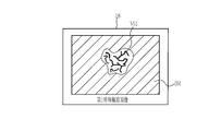
- the first image displays an image showing the background mucous membrane BM and the surface blood vessel VS1 of the observation target.
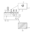
- the first image is obtained based on the first illumination light including violet light, blue light, green light, and red light.
- the violet light V and the blue light B of the first illumination light reach the surface layer where the surface blood vessels VS1 are distributed. Therefore, the purple light image VP obtained based on the reflected light of the purple light V and the blue light B includes the image of the surface blood vessel VS1.
- the light intensity of the violet light V is stronger than the light intensity of the blue light B, and hence the violet light image VP is used.
- the green light G and the red light R of the first illumination light are deep to the background mucous membrane BM distributed at a position deeper than the superficial blood vessel VS1 and the deep blood vessel VS2 (the blood vessel located deeper than the superficial blood vessel VS1).
- the green and red light image GRP obtained based on the reflected light of the green light G and the red light R includes the image of the background mucous membrane BM.
- the first image is an image in which the purple light image VP and the green and red light images GRP are combined, the images of the background mucous membrane BM and the surface blood vessel VS1 are displayed.
- the second special observation image processing unit 68 generates a second image that has undergone image processing such as saturation enhancement processing, hue enhancement processing, and structure enhancement processing based on the second image signal.
- image processing such as saturation enhancement processing, hue enhancement processing, and structure enhancement processing based on the second image signal.
- the second special observation image processing unit 68 is provided with a parameter for the second image to be multiplied with the second image signal in order to perform the image processing of the second image.
- the second special observation image processing unit 68 does not perform the superficial layer blood vessel enhancing process for enhancing the deep layer blood vessel, but the deep layer blood vessel enhancing process may be performed depending on the processing load.
- the second image displays an image showing the background mucous membrane BM and the deep blood vessel VS2 of the observation target.
- the second image is obtained based on the second illumination light including violet light, blue light, green light, and red light.
- the purple light V and the blue light B of the second illumination light reach a deep layer where the deep blood vessels VS2 are distributed. Therefore, the blue light image BP obtained based on the reflected light of the violet light V and the blue light B includes the image of the deep blood vessel VS2. Note that here, the light intensity of the blue light B is stronger than the light intensity of the violet light V, and thus the blue light image BP is used.
- the green light G and the red light R of the second illumination light are deep to the background mucous membrane BM distributed at a position deeper than the superficial blood vessel VS1 and the deep blood vessel VS2 (the blood vessel deeper than the superficial blood vessel VS1).
- the green and red light image GRP obtained based on the reflected light of the green light G and the red light R includes the image of the background mucous membrane BM.
- the second image is an image in which the blue light image BP and the green and red light images GRP are combined, the images of the background mucous membrane BM and the deep layer blood vessel VS2 are displayed.
- the first special observation image is generated by the first image signal
- the second special observation image is generated by the second image signal
- the surface blood vessels are emphasized in the first special observation image. It is preferable that the second special observation image emphasize the middle-deep layer blood vessels located deeper than the surface layer blood vessels.
- the detecting unit 69 detects a blood vessel or a lesion from the normal image, the first image, and the second image. As described above, since the first image is an image showing the superficial blood vessels VS1 and the second image is an image showing the deep blood vessels VS2, these blood vessels can be detected by image processing. .. The blood vessel or lesion may be detected by image processing using a normal observation image in addition to the first image and the second image. Further, the detection unit 69 detects an abnormal portion in the first image or the second image and sets it as an abnormal image signal. The detection result of the blood vessel or the lesion is sent to the white balance unit 55 or the light source control unit 21.
- the display control unit 64 displays the normal image, the first image, and/or the second image input from the normal observation image processing unit 62 or the special observation image processing unit 63 as images that can be displayed on the monitor 18. Take control. An image corresponding to each observation mode is displayed under the control of the display control unit 64. In the normal observation mode, a normal image is displayed on the monitor 18. In the case of the first special light observation mode, the first image (see FIG. 12) is displayed on the monitor 18. In the second special light observation mode, the second image (see FIG. 14) is displayed on the monitor 18.
- the color first image and the second image are switched and displayed on the monitor 18 in accordance with the emission period of the first illumination light and the emission period of the second illumination light. That is, when the light emission period K(N) is 4 frames and the light emission period L(N) is 4 frames, the first display observation image is continuously displayed for 4 frames, and the second display observation image is displayed. Is displayed for four frames in a row.
- the multi-observation mode it is possible to automatically switch and display the two types of the first image and the second image without the user operating the mode switching SW 13a.
- the same observation target is displayed in the first image and the second image as long as the observation target does not move or the tip portion 12d of the endoscope 12 does not move.
- the appearance of the observation target is different due to the difference in the spectral information. That is, the visibility of superficial blood vessels is high in the first image, while the visibility of deep blood vessels is high in the second image. Therefore, the visibility of a plurality of blood vessels having different depths can be improved by switching and displaying the first image and the second image.
- the still image saving control unit 66 controls the still image saving unit 65 to save the image obtained at the timing of the still image acquisition instruction as a still image according to the instruction of the still image acquisition instruction unit 13b. I do.
- the normal image obtained at the timing of the still image acquisition instruction is stored in the still image storage unit 65 as a still image.
- the first special observation image obtained at the timing of the still image acquisition instruction is stored in the still image storage unit 65 as a still image.
- the second special observation image obtained at the timing of the still image acquisition instruction is stored in the still image storage unit 65 as a still image.
- a set of display observation images of the first special observation image and the second special observation image obtained at the timing of the still image acquisition instruction is stored in the still image storage unit 65.
- the light amount setting unit 56 calculates the brightness of the subject from the image signal obtained in the normal light observation mode in the brightness calculation unit 55.
- the light amount setting unit 56 sets the light amount of the normal light based on the calculated brightness of the subject.
- the light source control unit 21 controls the light amount of the normal light based on the light amount of the normal light set by the light amount setting unit 56.
- the brightness calculator 55 calculates the first brightness D1 of the subject from the first image signal.
- the light amount setting unit 56 sets the light amount of the first illumination light from the first brightness D1.
- the light source control unit 21 controls the light amount of the first illumination light based on the light amount of the first illumination light set by the light amount setting unit 56.
- the brightness calculation unit 55 calculates the second brightness D2 of the subject from the second image signal.
- the light amount setting unit 56 sets the light amount of the second illumination light from the second brightness D2. Then, the light source control unit 21 controls the light amount of the second illumination light based on the light amount of the second illumination light set by the light amount setting unit 56.
- the brightness calculation unit 55 obtains the first brightness D1 or the second brightness D2 by using the pixel values of all the pixels of the first image signal or the second image signal, and also calculates the first image signal or the second brightness D2.
- the first brightness D1 or the second brightness D2 may be obtained based on the average of pixel values other than blood vessels or lesions in the image signal. Further, the first brightness D1 or the second brightness D2 may be obtained from the average of the pixel values of the first image signal or the second image signal other than the abnormal pixel including at least one of the dark part and the halation. Good. Further, based on the average value of the pixel values of the normal image signals other than the first image signal or the second image signal including the abnormal pixel in the first image signal group or the second image signal group, the first brightness D1 or 2 The brightness D2 may be obtained.
- the first brightness D1(1), D2(3) is calculated from the first image signal, and the first illumination is calculated based on the first brightness (1), D2(3).
- the second image is displayed.
- the second brightness D2(2), D2(4) is calculated from the signal, and the light amount of the second illumination light is set based on the second brightness D2(2), D2(4).
- the set light amount adjusting unit 57 adjusts the light amount.
- the set light amount adjustment unit 57 adjusts the light amount for the light amount of the first illumination light set at the second switching timing T2 for switching from the second illumination light to the first illumination light.
- the information about the first switching timing T1 in the light emitting period L(N ⁇ 2) before the light emitting period L(N) is used to set at the first switching timing T1 in the light emitting period L(N).
- the light amount of the second illumination light is adjusted or the information on the second switching timing T2 of the light emission period K(N-2) before the light emission period K(N) is used to change the light emission period K(N).
- the light amount of the first illumination light set at the second switching timing T2 is adjusted.
- the setting light amount adjustment unit 57 uses the information on the first switching timing T1 of the light emitting period L(2) before the light emitting period L(4) to perform the first switching of the light emitting period L(4).
- the light amount of the second illumination light set at the timing T1 is adjusted, or the information about the second switching timing T2 of the light emission period K(1) before the light emission period K(3) is used to generate the light emission period K(3 )
- the light amount of the first illumination light set at the second switching timing T2 is adjusted.
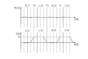
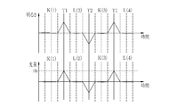
- the first switching timing T1 is included in both the light emission period K(N) of the first illumination light and the light emission period L(N+1) of the second illumination light.
- light emission is performed. It corresponds to both the light emission timing of the last frame of the period K(3) and the light emission timing of the first frame of the light emission period L(4).
- the second switching timing T2 is included in both the light emission period L(N) of the second illumination light and the light emission period K(N+1) of the first illumination light, and in the case of FIG. 16, for example, the light emission period L2. It corresponds to both the light emission timing of the last frame of (2) and the light emission timing of the first frame of the light emission period K(3).
- the light amount is calculated using the adjustment coefficient X(2) based on the second brightness D2(2) * at the first switching timing T1 and the preset target brightness V. Adjust.
- the light amount H2(4) * of the second illumination light whose light amount has been adjusted is sent to the light source controller 21, and the light source controller 21 calculates the light amount H2(4) * of the second illumination light whose light amount has been adjusted. The light amount of the second illumination light is controlled.
- the second light is controlled by the AE (Auto Exposure) control by the light source control unit 21 along with the switching from the first light to the second light.
- the brightness can be made substantially the same in the light emission period K(1) of the first illumination light and the light emission period L(2) of the second illumination light.
- the light source control unit is switched with the switching from the first illumination light to the second illumination light.
- the second information using the information (adjustment coefficient X(2)) regarding the first switching timing T1 is used as in the present embodiment. If the light amount of the illumination light is not adjusted, the brightness will change at the first switching timing T1 at which the light emission period K(1) is switched to the light emission period L(2). This can happen because the subject has a high reflectance in the green band, unlike a standard subject.
- the AE control converges to an appropriate brightness. Note that the above-described fluctuation in brightness may occur even at the second switching timing T2 when the light emitting period L(2) is switched to the light emitting period K(3).
- the first switching timing T1 is set.
- the light amount of the second illumination light is adjusted by using the information (adjustment coefficient X(2)) regarding. Then, by illuminating the second illumination light based on the light quantity H2(4) * after the light quantity adjustment, it is possible to suppress the light quantity variation at the first switching timing T1 and to reduce the light emission period K(3).
- the brightness of the light emitting period L(4) can be made substantially the same.
- the first switching timing T1 of the light emitting period L(N) is set. 2
- the light amount of the illumination light is adjusted, or the information about the second switching timing T2 of the light emission period K(NP) before the light emission period K(N) is used to determine the second light emission period K(N).
- the light amount of the first illumination light set at the switching timing T2 may be adjusted. Note that P is an even number smaller than N.
- the specific adjustment coefficient X is multiplied by the light quantity H2(6).
- the light amount H2(6) * of the second illumination light whose light amount has been adjusted is sent to the light source control unit 21, and the light source control unit 21 calculates the light amount H2(6) * of the second illumination light whose light amount has been adjusted. The light amount of the second illumination light is controlled.
- H2(N) * (target brightness) ⁇ ( ⁇ 1/(second brightness D2(N-2) at the first switching timing T1 in the light emission period L(N-2)+ ⁇ 2/(second at the first switching timing T1 in the light emission period L(N-4) Brightness D2(N-4)+...+ ⁇ n/(second brightness D2(Nn) at the first switching timing T1 of the light emission period L(Nn))
- ⁇ 1+ ⁇ 2+... ⁇ n 1.
- n is an even number smaller than N.
- the information about the second switching timing T2 in the light emitting period K(N-1) before the light emitting period L(N) is used to set at the first switching timing T1 in the light emitting period L(N).
- the light amount of the second illumination light is adjusted or the information about the first switching timing T1 of the light emitting period L(N-1) before the light emitting period K(N) is used to change the light emitting period K(N).
- the light amount of the first illumination light set at the second switching timing T2 is adjusted.
- the light quantity H2(4) is the light quantity of the second illumination light set at the first switching timing T1 in the light emission period L(4)
- the light quantity H2(4) is multiplied by the adjustment coefficient Y(3).
- the light amount H2(4) * of the second illumination light whose light amount has been adjusted is sent to the light source controller 21, and the light source controller 21 calculates the light amount H2(4) * of the second illumination light whose light amount has been adjusted.
- the light amount of the second illumination light is controlled.
- the second switching timing T2 of the plurality of light emitting periods K(NQ) and the first switching timing T1 of the plurality of light emitting periods L(NP) prior to the light emitting period L(N) is used. Adjusts the light amount of the second illumination light set at the first switching timing T1 of the light emitting period L(N), or adjusts the light amount of the second illumination light in the plurality of light emitting periods L(N ⁇ Q) before the light emitting period K(N).
- the light amount of the first illumination light set at the second switching timing T2 of the light emission period K(N) is adjusted by using the information about the first switching timing T1 and the second switching timing T2 of the plurality of light emission periods K(NP). You may. Note that P is an even number smaller than N and Q is an odd number smaller than N.
- the specific adjustment coefficient Y is multiplied by the light quantity H2(6).
- the light amount H2(6) * of the second illumination light whose light amount has been adjusted is sent to the light source control unit 21, and the light source control unit 21 calculates the light amount H2(6) * of the second illumination light whose light amount has been adjusted.
- the light amount of the second illumination light is controlled.
- H2(N) * 1/(Target brightness) ⁇ ( ⁇ 1/(first brightness D1(N-1) at second switching timing T2 in light emitting period K(N-1)+ ⁇ 2/(first at second switching timing T2 in light emitting period K(N-3) Brightness D1(N-3)+...+ ⁇ n/(second brightness D2(Nm) at the first switching timing T1 in the light emission period (Nm) + (Target brightness) ⁇ ( ⁇ 1/(second brightness D2(N-2) at the first switching timing T1 in the light emission period L(N-2)+ ⁇ 2/(second at the first switching timing T1 in the light emission period L(N-4) Brightness D2(N-4)+...+ ⁇ n/(second brightness D2(Nn) at the first
- the light quantity of the second illumination light at the first switching timing T1 is constantly adjusted, and the light quantity of the first illumination light at the second switching timing T2 is adjusted. Although it is adjusted, the light amount of the second illumination light at the first switching timing T1 is adjusted only when the first brightness D1 or the second brightness is within a predetermined target brightness range. The light amount of the first illumination light at the second switching timing T2 may be adjusted.
- the light quantity setting unit 56 when adjusting the light quantity of the second illumination light set by the light quantity setting unit 56 at the first switching timing T1 in the light emission period L(4) of the second illumination light, When the second brightness D2(2) * is within the target brightness range, the light amount of the second illumination light at the first switching timing T1 is not adjusted, and the second brightness D2(2) * is the target. When it is outside the range of brightness, it is preferable to adjust the light amount of the second illumination light at the first switching timing T1.
- the hardware structure of the processing unit included in the processor device 16 is the following various processors. For various processors, change the circuit configuration after manufacturing such as CPU (Central Processing Unit) and FPGA (Field Programmable Gate Array), which are general-purpose processors that execute software (programs) and function as various processing units
- a programmable logic device (PLD) that is a possible processor, a GPU (Graphical Processing Unit), and a dedicated electric circuit that is a processor having a circuit configuration specifically designed to execute various processes are included.
- One processing unit may be configured by one of these various processors, or a combination of two or more processors of the same type or different types (for example, a plurality of FPGAs, a combination of CPUs and FPGAs, a combination of CPUs and GPUs). Combination). Also, the plurality of processing units may be configured by one processor. As an example of configuring a plurality of processing units by one processor, firstly, one processor is configured by a combination of one or more CPUs and software, as represented by a computer such as a client or a server. There is a form in which this processor functions as a plurality of processing units.
- a processor that realizes the functions of the entire system including a plurality of processing units by one IC (Integrated Circuit) chip is used, as represented by a system-on-chip (SoC).
- SoC system-on-chip
- the various processing units are configured by using one or more of the above various processors as a hardware structure.
- the hardware-like structure of these various processors is more specifically an electric circuit (circuitry) in which circuit elements such as semiconductor elements are combined.
- the present invention relates to a processor device incorporated in an endoscope system as in the first or second embodiment, a processor device incorporated in a capsule endoscope system, or various medical image processing devices. Can be applied.
Landscapes
- Health & Medical Sciences (AREA)
- Life Sciences & Earth Sciences (AREA)
- Surgery (AREA)
- Physics & Mathematics (AREA)
- Engineering & Computer Science (AREA)
- Optics & Photonics (AREA)
- Biophysics (AREA)
- Animal Behavior & Ethology (AREA)
- Pathology (AREA)
- Radiology & Medical Imaging (AREA)
- Veterinary Medicine (AREA)
- Biomedical Technology (AREA)
- Heart & Thoracic Surgery (AREA)
- Medical Informatics (AREA)
- Molecular Biology (AREA)
- Nuclear Medicine, Radiotherapy & Molecular Imaging (AREA)
- General Health & Medical Sciences (AREA)
- Public Health (AREA)
- Signal Processing (AREA)
- Astronomy & Astrophysics (AREA)
- General Physics & Mathematics (AREA)
- Microelectronics & Electronic Packaging (AREA)
- Endoscopes (AREA)
Abstract
複数の光を切り替えて照明する場合において、被写体の変化に合わせて、各光の照明光の光量を制御することができる内視鏡システムを提供する。 設定光量調整部(57)は、第1照明光から第2照明光に切り替える第1切替タイミングT1において設定された第2照明光の光量を調整すること、第2照明光から第1照明光に切り替える第2切替タイミングT2において設定された第1照明光の光量を調整することの少なくともいずれかを行う。
Description
本発明は、複数種類の画像を切り替えて表示する内視鏡システムに関する。
近年の医療分野では、光源装置、内視鏡、プロセッサ装置を備える内視鏡システムが広く用いられている。内視鏡システムでは、内視鏡から観察対象に照明光を照射し、その照明光で照明中の観察対象を内視鏡の撮像素子で撮像して得られるRGB画像信号に基づいて、観察対象の画像をモニタ上に表示する。
また、近年では、診断の目的に応じて、互いに波長域が異なる複数の照明光を観察対象に照明することが行われている。例えば、特許文献1では、ピーク波長が422nmのNB1光と、ピーク波長が460~470nmのNB2光との2つの青色の狭帯域光を交互に照明することによって、観察対象に含まれる血管中の酸素飽和度を取得することが記載されている。また、特許文献2では、B1領域(第1のB領域:390nmから440nm)にピークを有する光と、B2領域(第2のB領域:440nmから490nm)にピークを有する光とを観察対象に照明し、B1領域の光及びB2領域の光の両方に感度を有するB画素を含む撮像素子によって撮像を行うことにより、表層血管の解像情報を得ることが記載されている。また、特許文献3には、中心波長405nmの紫色光、中心波長445nmの青色レーザ光、及び青色レーザ光によって励起発光する励起発光を用いて、生体組織の所望の組織情報を、診断に適したより明瞭な状態で取得することが記載されている。
近年では、内視鏡分野においては、背景粘膜以外の生体情報、例えば、深さが異なる血管や深さ、高さが異なる腺管構造などに着目する診断が行われている。このような診断においては、ユーザーに対して、背景粘膜以外の複数の情報をそれぞれ把握できるように表示する必要がある。このような複数の情報をそれぞれ表示する方法として、生体組織への深達度が異なる複数波長の光を自動で周期的に切り替えて照明し、それらの照明によって得られる複数の画像を切り替えて表示する方法が考えられる。例えば、表層血管など表層の情報と深層血管など深層の情報を得るためには、表層にまで深達度を有する短波光と深層にまで深達度を有する中波長光を切り替えて照明し、短波光の照明により得られる表層画像と中波長光の照明により得られる深層画像とを切り替えて表示する。このような切替表示を行うことにより、表層画像と深層画像の差分が表示されるため、異なる生体情報を分離して表示することができる。したがって、表層情報と深層情報との異なる生体情報を把握することができる。
以上のように、各波長の光を切り替えて照明する場合には、各波長の光の光量が、被写体の明るさに合わせて、適正に制御する必要がある。しかしながら、観察部位の違い、個人差、炎症等の疾患の有無、または色素散布の有無等の被写体の変化により、標準的な被写体と分光反射率が異なり、複数波長の光で撮影したそれぞれの画像の明るさ、色調等が大きく異なる場合には、各波長の光の切替時に目標明るさとの差が大きい場合には、各波長の光の光量が、被写体の明るさに対応しないことがある。
本発明は、複数の光を切り替えて照明する場合において、被写体の変化に合わせて、各光の照明光の光量を制御することができる内視鏡システムを提供することを目的とする。
本発明の内視鏡システムは、第1照明光と、第1照明光とは異なる発光スペクトルを有する第2照明光とを発光する光源部と、第1プロセッサと、第2プロセッサとを備え、第1プロセッサは、第1照明光と第2照明光とを自動的に切り替えて発光する制御を行う場合において、第1照明光を発光する発光期間K(N)と第2照明光を発光する発光期間L(N)は、それぞれ少なくとも1フレーム以上の発光期間であるとし、第2プロセッサは、第1照明光の発光期間K(N)において第1照明光により照明された被写体を撮像して得られる第1画像信号を含む第1画像信号群と、第2照明光の発光期間L(N)において第2照明光により照明された被写体を撮像して得られる第2画像信号を含む第2画像信号群とを取得し、第1画像信号から被写体の第1明るさD1を算出し、第2画像信号から被写体の第2明るさD2を算出し、第1明るさ又は第2明るさに基づいて、第1照明光又は第2照明光の光量を設定し、第1照明光から第2照明光に切り替える第1切替タイミングにおいて設定された第2照明光の光量を調整すること、第2照明光から第1照明光に切り替える第2切替タイミングにおいて設定された第1照明光の光量を調整することの少なくともいずれかを行う。
第2プロセッサは、発光期間L(N)よりも前の発光期間L(N-2)の第1切替タイミングT1に関する情報を用いて、発光期間L(N)の第1切替タイミングT1で設定した第2照明光の光量を調整し、又は、発光期間K(N)よりも前の発光期間K(N-2)の第2切替タイミングT2に関する情報を用いて、発光期間K(N)の第2切替タイミングT2で設定した第1照明光の光量を調整することの少なくともいずれかを行うことが好ましい。
N=4とし、発光期間L(4)の第1切替タイミングT1で設定した第2照明光の光量を調整する場合には、発光期間L(2)の第1切替タイミングT1に関する情報として、目標明るさを、第1切替タイミングT1の第2明るさD2(2)*で除して得られる調整係数X(2)を、第2照明光の光量に掛け合わせて行うことが好ましい。
第2プロセッサは、発光期間L(N)よりも前の複数の発光期間L(N-P)の第1切替タイミングT1に関する情報を用いて、発光期間L(N)の第1切替タイミングT1で設定した第2照明光の光量を調整し、又は、発光期間K(N)よりも前の発光期間K(N-P)の第2切替タイミングT2に関する情報を用いて、発光期間K(N)の第2切替タイミングT2で設定した第1照明光の光量を調整することの少なくともいずれかを行うことが好ましい。
第1切替タイミングT1の第2明るさD2には、複数の発光期間L(N-P)の第1切替タイミングT1の第2明るさのそれぞれを示す複数の第2明るさD2(N-P)が含まれ、第2プロセッサが、発光期間L(N)の第1切替タイミングT1で設定した第2照明光の光量を調整する場合には、複数の発光期間L(N-P)の第1切替タイミングT1に関する情報として、目標明るさを、複数の第2明るさD2(N-P)のそれぞれに対して、重み付け係数を掛けて加算した値で除して得られる特定調整係数Xを、第2照明光の光量に掛け合わせて行われることが好ましい。
第2プロセッサは、発光期間L(N)よりも前の発光期間K(N-1)の第2切替タイミングT2に関する情報を用いて、発光期間L(N)の第1切替タイミングT1で設定した第2照明光の光量を調整し、又は、発光期間K(N)よりも前の発光期間L(N-1)の第1切替タイミングT1に関する情報を用いて、発光期間K(N)の第2切替タイミングT2で設定した第1照明光の光量を調整することの少なくともいずれかを行うことが好ましい。
N=4とし、発光期間L(4)の第1切替タイミングT1で設定した第2照明光の光量を調整する場合には、発光期間K(3)の第2切替タイミングT2に関する情報として、発光期間K(3)のうち第2切替タイミングの第1明るさD1(3)*を、目標明るさで除して得られる調整係数Y(3)を、第2照明光の光量に掛け合わせて行うことが好ましい。
第2プロセッサは、発光期間L(N)よりも前の複数の発光期間K(N-Q)の第2切替タイミングT2及び複数の発光期間L(N-P)の第1切替タイミングT1に関する情報を用いて、発光期間L(N)の第1切替タイミングT1で設定した第2照明光の光量を調整し、又は、発光期間K(N)よりも前の複数の発光期間L(N-Q)の第1切替タイミングT1及び複数の発光期間K(N-P)の第2切替タイミングT2に関する情報を用いて、発光期間K(N)の第2切替タイミングT2で設定した第1照明光の光量を調整することの少なくともいずれかを行うことが好ましい。
N=6とし、第2プロセッサが、発光期間L(6)の第1切替タイミングT1で設定した第2照明光の光量を調整する場合には、発光期間K(5)のうち第2切替タイミングT2の第1明るさD1(5)*、発光期間L(4)の第1切替タイミングT1の第2明るさD2(4)*、及び予め設定された目標明るさVとに基づく特定調整係数Yを、第2照明光の光量に掛け合わせて行うことが好ましい。
第1明るさ又は第2明るさは、第1画像信号又は第2画像信号のうち血管または病変以外の画素値の平均に基づいて求められることが好ましい。第1明るさ又は第2明るさは、第1画像信号又は第2画像信号のうち暗部、ハレーションの少なくともいずれかを含む異常画素以外の画素値の平均、又は、第1画像信号群又は第2画像信号群のうち異常画素を含む第1画像信号又は第2画像信号以外の正常画像信号の画素値の平均値に基づいて求められることが好ましい。第2プロセッサは、第1明るさ又は第2明るさが予め定めた目標明るさ範囲の範囲内である場合にのみ、第2照明光の光量の調整、又は、第1照明光の光量の調整を行うことが好ましい。
本発明によれば、複数の光を切り替えて照明する場合において、被写体の変化に合わせて、各光の照明光の光量を制御することができる。
[第1実施形態]
図1に示すように、第1実施形態の内視鏡システム10は、内視鏡12と、光源装置14と、プロセッサ装置16と、モニタ18(表示部)と、ユーザーインターフェース19とを有する。内視鏡12は光源装置14と光学的に接続され、且つ、プロセッサ装置16と電気的に接続される。内視鏡12は、被検体内に挿入される挿入部12aと、挿入部12aの基端部分に設けられた操作部12bと、挿入部12aの先端側に設けられる湾曲部12c及び先端部12dを有している。操作部12bのアングルノブ12eを操作することにより、湾曲部12cは湾曲動作する。この湾曲動作に伴って、先端部12dが所望の方向に向けられる。なお、ユーザーインターフェース19は図示したキーボードの他、マウスなどが含まれる。
図1に示すように、第1実施形態の内視鏡システム10は、内視鏡12と、光源装置14と、プロセッサ装置16と、モニタ18(表示部)と、ユーザーインターフェース19とを有する。内視鏡12は光源装置14と光学的に接続され、且つ、プロセッサ装置16と電気的に接続される。内視鏡12は、被検体内に挿入される挿入部12aと、挿入部12aの基端部分に設けられた操作部12bと、挿入部12aの先端側に設けられる湾曲部12c及び先端部12dを有している。操作部12bのアングルノブ12eを操作することにより、湾曲部12cは湾曲動作する。この湾曲動作に伴って、先端部12dが所望の方向に向けられる。なお、ユーザーインターフェース19は図示したキーボードの他、マウスなどが含まれる。
また、操作部12bには、アングルノブ12eの他、モード切替SW13a、静止画取得指示部13bが設けられている。モード切替SW13aは、通常光観察モードと、第1特殊光観察モードと、第2特殊光観察モードと、マルチ観察モードとの切替操作に用いられる。通常光観察モードは、通常画像をモニタ18上に表示するモードである。第1特殊光観察モードは、表層血管などの表層情報を強調した第1特殊観察画像をモニタ18上に表示するモードである。第2特殊光観察モードは、深層血管などの深層情報を強調した第2特殊観察画像をモニタ18上に表示するモードである。マルチ観察モードは、第1特殊観察画像(以下、第1画像という)と第2特殊観察画像(以下、第2画像という)とを自動的に切り替えてモニタ18に表示するモードである。なお、モードを切り替えるためには、モード切替SW13aの他に、フットスイッチ等を用いてもよい。
プロセッサ装置16は、モニタ18及びユーザーインターフェース19と電気的に接続される。モニタ18は、画像情報等を出力表示する。ユーザーインターフェース19は、機能設定等の入力操作を受け付けるUI(User Interface:ユーザーインターフェース)として機能する。なお、プロセッサ装置16には、画像情報等を記録する外付けの記録部(図示省略)を接続してもよい。
図2に示すように、光源装置14は、光源部20と、光源制御部21と、光路結合部23と、発光期間設定部24とを有している。光源部20は、V-LED(Violet Light Emitting Diode)20a、B-LED(Blue Light Emitting Diode)20b、G-LED(Green Light Emitting Diode)20c、R-LED(Red Light Emitting Diode)20dを有している。光源装置14には、各種制御に関するプログラムがプログラム用メモリ(図示しない)に組み込まれている。第1プロセッサから構成される光源制御部21が、プログラム用メモリに組み込まれたプログラムを実行することによって、光源制御部21の機能が実現する。具体的には、光源制御部21は、LED20a~20dの駆動を制御するための機能が実現する。光路結合部23は、4色のLED20a~20dから発せられる4色の光の光路を結合する。光路結合部23で結合された光は、挿入部12a内に挿通されたライトガイド41及び照明レンズ45を介して、被検体内に照射される。なお、LEDの代わりに、LD(Laser Diode)を用いてもよい。発光期間設定部24は、複数の照明光のそれぞれの発光期間を設定する。
図3に示すように、V-LED20aは、中心波長405±10nm、波長範囲380~420nmの紫色光Vを発生する。B-LED20bは、中心波長460±10nm、波長範囲420~500nmの青色光Bを発生する。G-LED20cは、波長範囲が480~600nmに及ぶ緑色光Gを発生する。R-LED20dは、中心波長620~630nmで、波長範囲が600~650nmに及ぶ赤色光Rを発生する。
光源制御部21は、V-LED20a、B-LED20b、G-LED20c、及びR-LED20dを制御する。また、光源制御部21は、通常光観察モード時には、紫色光V、青色光B、緑色光G、及び赤色光R間の光強度比がVc:Bc:Gc:Rcとなる通常光を発光するように、各LED20a~20dを制御する。
また、光源制御部21は、第1特殊光観察モード時には、紫色光V、青色光B、緑色光G、及び赤色光R間の光強度比がVs1:Bs1:Gs1:Rs1となる第1照明光を発光するように、各LED20a~20dを制御する。光強度比Vs1:Bs1:Gs1:Rs1は、第1照明光の光量条件に対応する。第1照明光は、表層血管を強調することが好ましい。そのため、第1照明光は、紫色光Vの光強度を青色光Bの光強度よりも大きくすることが好ましい。例えば、図4に示すように、紫色光Vの光強度Vs1と青色光Bの光強度Bs1との比率を「4:1」とする。
なお、本明細書において、光強度比は、少なくとも1つの半導体光源の比率が0(ゼロ)の場合を含む。したがって、各半導体光源のいずれか1つまたは2つ以上が点灯しない場合を含む。例えば、紫色光V、青色光B、緑色光G、及び赤色光R間の光強度比が1:0:0:0の場合のように、半導体光源の1つのみを点灯し、他の3つは点灯しない場合も、光強度比を有するものとする。
また、光源制御部21は、第2特殊光観察モード時には、紫色光V、青色光B、緑色光G、及び赤色光R間の光強度比がVs2:Bs2:Gs2:Rs2となる第2照明光を発光するように、各LED20a~20dを制御する。光強度比Vs2:Bs2:Gs2:Rs2は、第2照明光の光量条件に対応する。第2照明光は、深層血管を強調することが好ましいい。そのため、第2照明光は、青色光Bの光強度を紫色光Vの光強度よりも大きくすることが好ましい。例えば、図5に示すように、紫色光Vの光強度Vs2と青色光Bの光強度Bs2との比率を「1:3」とすることが好ましい。
光源制御部21は、マルチ観察モードに設定されている場合には、第1照明光と第2照明光とをそれぞれ発光期間K(N)と発光期間L(N)にて発光し、且つ、第1照明光と第2照明光とを自動的に切り替えて発光する制御を行う。発光期間K(N)と発光期間L(N)とは、それぞれ少なくとも1フレーム以上の発光期間を有する。なお、Nは自然数とし、Nが大きくなる程、時間的に進んでいることを示す。
より具体的には、例えば、図6に示すように、光源制御部21は、発光期間K(N)を4フレームとし、発光期間K(N)を4フレームとした場合、第1照明光が発光期間K(1)にて4フレーム続けて発光した後に、第2照明光が発光期間L(2)にて4フレーム続けて発光される。そして、この発光パターンを繰り返し行う。
なお、「フレーム」とは、観察対象を撮像する撮像センサ48(図2参照)を制御するための単位をいい、例えば、「1フレーム」とは、観察対象からの光で撮像センサ48を露光する露光期間と画像信号を読み出す読出期間とを少なくとも含む期間のことをいう。本実施形態においては、撮像の単位である「フレーム」に対応して発光期間K(N)または発光期間L(N)がそれぞれ定められている。
発光期間K(N)と発光期間L(N)は、光源制御部21に接続された発光期間設定部24によって、適宜変更が可能である。ユーザーインターフェース19の操作により、発光期間の変更操作を受け付けると、発光期間設定部24は、図7に示すような発光期間設定メニューをモニタ18上に表示する。発光期間K(N)は、例えば、2フレームから10フレームの間で変更可能である。各発光期間については、スライドバー26a上に割り当てられている。
発光期間K(N)を変更する場合には、ユーザーインターフェース19を操作して、スライドバー26a上の変更したい発光期間を示す位置にスライダ27aを合わせることで、発光期間K(N)が変更される。発光期間K(N)についても、ユーザーインターフェース19を操作して、スライドバー26b(例えば、2フレームから10フレームの発光期間が割り当てられている)上の変更したい発光期間を示す位置にスライダ27bを合わせることで、発光期間L(N)が変更される。
図2に示すように、ライトガイド41は、内視鏡12及びユニバーサルコード(内視鏡12と光源装置14及びプロセッサ装置16とを接続するコード)内に内蔵されており、光路結合部23で結合された光を内視鏡12の先端部12dまで伝搬する。なお、ライトガイド41としては、マルチモードファイバを使用することができる。一例として、コア径105μm、クラッド径125μm、外皮となる保護層を含めた径がφ0.3~0.5mmの細径なファイバケーブルを使用することができる。
内視鏡12の先端部12dには、照明光学系30aと撮像光学系30bが設けられている。照明光学系30aは照明レンズ45を有しており、この照明レンズ45を介して、ライトガイド41からの光が観察対象に照射される。撮像光学系30bは、対物レンズ46及び撮像センサ48を有している。観察対象からの反射光は、対物レンズ46を介して、撮像センサ48に入射する。これにより、撮像センサ48に観察対象の反射像が結像される。
撮像センサ48はカラーの撮像センサであり、被検体の反射像を撮像して画像信号を出力する。この撮像センサ48は、CCD(Charge Coupled Device)撮像センサやCMOS(Complementary Metal-Oxide Semiconductor)撮像センサ等であることが好ましい。本発明で用いられる撮像センサ48は、R(赤)、G(緑)及びB(青)の3色のRGB画像信号を得るためのカラーの撮像センサ、即ち、Rフィルタが設けられたR画素、Gフィルタが設けられたG画素、Bフィルタが設けられたB画素を備えた、いわゆるRGB撮像センサである。
図8に示すように、Bフィルタ48bは、紫色帯域の光、青色帯域の光、及び緑色帯域の光のうち短波側の光を透過させる。Gフィルタ48gは、緑色帯域の光、青色帯域の光の長波側の光、及び赤色帯域の光の短波側の光を透過させる。Rフィルタ48rは、赤色帯域の光、緑色帯域の短波側の光を透過させる。したがって、撮像センサ48のうち、B画素は紫色光V及び青色光Bに感度を有し、G画素は青色光B、緑色光G、及び赤色光Rに感度を有し、R画素は緑色光G及び赤色光Rに感度を有している。
なお、撮像センサ48としては、RGBのカラーの撮像センサの代わりに、C(シアン)、M(マゼンタ)、Y(イエロー)及びG(緑)の補色フィルタを備えた、いわゆる補色撮像センサであっても良い。補色撮像センサを用いる場合には、CMYGの4色の画像信号が出力されるため、補色-原色色変換によって、CMYGの4色の画像信号をRGBの3色の画像信号に変換する必要がある。また、撮像センサ48はカラーフィルタを設けていないモノクロ撮像センサであっても良い。この場合、光源制御部21は青色光B、緑色光G、及び赤色光Rを時分割で点灯させて、撮像信号の処理では同時化処理を加える必要がある。
図2に示すように、撮像センサ48から出力される画像信号は、CDS/AGC回路50に送信される。CDS/AGC回路50は、アナログ信号である画像信号に相関二重サンプリング(CDS(Correlated Double Sampling))又は自動利得制御(AGC(Auto Gain Control))を行う。CDS/AGC回路50を経た画像信号は、A/D変換器(A/D(Analog /Digital)コンバータ)51により、デジタル画像信号に変換される。A/D変換されたデジタル画像信号は、プロセッサ装置16に入力される。
プロセッサ装置16では、各種処理又は制御に関するプログラムがプログラム用メモリ(図示しない)に組み込まれている。第2プロセッサによって構成されるプロセッサ装置16内の中央制御部(図示しない)によって、プログラム用メモリに組み込まれたプログラムを実行することによって、プロセッサ装置16は、画像取得部52と、DSP(Digital Signal Processor)54と、ノイズ除去部58と、信号切替部60と、通常観察画像処理部62と、特殊観察画像処理部63と、表示制御部64と、静止画保存部65と、静止画保存制御部66との機能が実現する。上記プログラムの実行に伴って、DSP54に含まれる後述の明るさ算出部55、光量設定部56、及び設定光量調整部57の機能も実現する。
画像取得部52は、内視鏡12において観察対象を撮像することにより得られた観察画像を取得する。具体的には、観察画像として、内視鏡12からのデジタルのカラー画像信号が画像取得部52に入力される。カラー画像信号は、撮像センサ48のR画素から出力される赤色信号と、撮像センサ48のG画素から出力される緑色信号と、撮像センサ48のB画素から出力される青色信号とから構成される。
図9に示すように、画像取得部52は、発光期間K(N)において第1画像信号群を取得する。第1画像信号群は、発光期間K(N)において第1照明光により照明された被写体を撮像した複数の第1画像信号SP1を含む。また、画像取得部52は、発光期間L(N)において第2画像信号群を取得する。第2画像信号群は、発光期間L(N)において第2照明光により照明された被写体を撮像した複数の第2画像信号SP2を含む。本実施形態では、マルチ観察モードに設定されている場合には、光源制御部21は、第1照明光と第2照明光とをそれぞれ発光期間K(N)と発光期間L(N)にて発光し、且つ、第1照明光と第2照明光とを自動的に切り替えて発光する制御を行うため、画像取得部52は、時間の経過により、第1画像信号群、第2画像信号群の順に、周期的に画像を取得する。
発光期間K(N)と発光期間L(N)とは、それぞれ少なくとも1フレーム以上の発光期間を有するため、第1画像信号群と第2画像信号群とは、それぞれ少なくとも1つ以上の第1画像信号SP1と第2画像信号SP2とを含む。本実施形態では、発光期間K(N)と発光期間L(N)とは、どちらも4フレームの発光期間である。したがって、発光期間K(N)では。4つの第1画像信号SP1を含む第1画像信号群が取得され、発光期間L(N)では、4つの第2画像信号SP2を含む第2画像信号群が取得される。
DSP56は、受信した画像信号に対して、欠陥補正処理、オフセット処理、ホワイトバランス処理、リニアマトリクス処理、ガンマ変換処理、又はデモザイク処理等の各種信号処理を施す。また、図10に示すように、DSP54は、明るさ算出部55と、光量設定部56と、設定光量調整部57とを備える。光量設定部55又は設定光量調整部56で得られた通常光と第1照明光又は第2照明光の光量に関する情報は、光源制御部21に送られる。光源制御部21では、光量設定部55又は設定光量調整部56からの光量に関する情報に基づいて、通常光と第1照明光又は第2照明光の光量の制御を行う。上記の明るさ算出部55、光量設定部56、及び設定光量調整部57の詳細については、後述する。
欠陥補正処理では、撮像センサ48の欠陥画素の信号が補正される。オフセット処理では、欠陥補正処理が施された画像信号から暗電流成分が除かれ、正確な零レベルが設定される。ホワイトバランス処理は、第1画像信号に第1ゲイン係数をかけ合わせて、また、第2画像信号に第2ゲイン係数をかけ合わせて行う。ホワイトバランス処理では、オフセット処理後の画像信号にゲインを乗じることにより信号レベルが整えられる。ホワイトバランス処理後の画像信号には、色再現性を高めるためのリニアマトリクス処理が施される。その後、ガンマ変換処理によって明るさや彩度が整えられる。リニアマトリクス処理後の画像信号には、デモザイク処理(等方化処理、同時化処理とも言う)が施され、各画素で不足した色の信号が補間によって生成される。このデモザイク処理によって、全画素が各色の信号を有するようになる。
ノイズ除去部58は、DSP56でガンマ補正等が施された画像信号に対してノイズ除去処理(例えば移動平均法やメディアンフィルタ法等)を施すことによって、画像信号からノイズを除去する。ノイズが除去された画像信号は、信号切替部60に送信される。
信号切替部60は、モード切替SW13aにより、通常光観察モードにセットされている場合には、通常光の照明及び撮像で得られた通常光用画像信号を通常観察画像処理部62に送信する。図11に示すように、特殊観察画像処理部63は、第1特殊観察画像処理部67、第2特殊観察画像処理部68、及び検出部69を含む。そして、第1特殊光観察モードにセットされている場合には、第1照明光の照明及び撮像で得られた第1画像信号を第1特殊観察画像処理部67に送信する。第1画像信号には、撮像センサのR画素から出力される第1赤色信号と、撮像センサ48のG画素から出力される第1緑色信号と、撮像センサ48のB画素から出力される第1青色信号が含まれる。また、第2特殊光観察モードにセットされている場合には、第2照明光の照明及び撮像で得られた第2画像信号を第2特殊観察画像処理部63に送信する。第2画像信号には、撮像センサのR画素から出力される第2赤色信号と、撮像センサ48のG画素から出力される第2緑色信号と、撮像センサ48のB画素から出力される第2青色信号が含まれる。また、マルチ観察モードにセットされている場合には、第1照明光の照明及び撮像で得られた第1画像信号は第1特殊観察画像処理部67に送信され、第2照明光の照明及び撮像で得られた第2画像信号は第2特殊観察画像処理部63に送信される。
通常観察画像処理部62は、通常光観察モード時に得られたRGB画像信号に対して、通常画像用の画像処理を施す。通常画像用の画像処理には、通常画像用の構造強調処理などが含まれる。通常観察画像処理部62では、通常画像用の画像処理を行うために、RGB画像信号に対して掛け合わされる通常画像用パラメータが設けられている。通常画像用の画像処理が施されたRGB画像信号は、通常画像として、通常観察画像処理部62から表示制御部64に入力される。
第1特殊観察画像処理部67は、第1画像信号に基づいて、彩度強調処理、色相強調処理、及び構造強調処理などの画像処理が行われた第1画像を生成する。第1画像では、表層血管が多く含まれているとともに、背景粘膜の色も正確に再現されている。第1特殊観察画像処理部67では、第1画像の画像処理を行うために、第1画像信号に対して掛け合わされる第1画像用のパラメータが設けられている。なお、第1特殊観察画像処理部67では、表層血管を強調する表層血管強調処理は行わないが、処理負荷の状況によっては、表層血管強調処理を行うようにしてもよい。
第1画像により、図12に示すように、観察対象のうち背景粘膜BM、及び、表層血管VS1が表された画像が表示される。第1画像は、紫色光、青色光、緑色光、及び赤色光を含む第1照明光に基づいて得られる。図13に示すように、第1照明光が観察対象に照明されると、第1照明光のうち紫色光V及び青色光Bは、表層血管VS1が分布する表層にまで深達する。したがって、紫色光V及び青色光Bの反射光に基づいて得られる紫色光画像VPには、表層血管VS1の像が含まれる。なお、ここでは、紫色光Vの光強度が青色光Bの光強度より強いため、紫色光画像VPとする。また、第1照明光のうち緑色光Gと赤色光Rは、表層血管VS1及び深層血管VS2(表層血管VS1よりも深い位置にある血管)よりもさらに深い位置に分布する背景粘膜BMにまで深達する。したがって、緑色光Gと赤色光Rの反射光に基づいて得られる緑及び赤色光画像GRPには、背景粘膜BMの像が含まれる。以上から、第1画像は紫色光画像VPと緑及び赤色光画像GRPを組み合わせた画像であるため、背景粘膜BM及び表層血管VS1の像が表示される。
第2特殊観察画像処理部68は、第2画像信号に基づいて、彩度強調処理、色相強調処理、及び構造強調処理などの画像処理が行われた第2画像を生成する。第2画像では、深層血管が多く含まれているとともに、背景粘膜の色も正確に再現されている。第2特殊観察画像処理部68では、第2画像の画像処理を行うために、第2画像信号に対して掛け合わされる第2画像用のパラメータが設けられている。なお、第2特殊観察画像処理部68では、深層血管を強調する表層血管強調処理は行わないが、処理負荷の状況によっては、深層血管強調処理を行うようにしてもよい。
第2画像により、図14に示すように、観察対象のうち背景粘膜BM、及び、深層血管VS2が表された画像が表示される。第2画像は、紫色光、青色光、緑色光、及び赤色光を含む第2照明光に基づいて得られる。図15に示すように、第1照明光が観察対象に照明されると、第2照明光のうち紫色光V及び青色光Bは、深層血管VS2が分布する深層にまで深達する。したがって、紫色光V及び青色光Bの反射光に基づいて得られる青色光画像BPには、深層血管VS2の像が含まれる。なお、ここでは、青色光Bの光強度が紫色光Vの光強度より強いため、青色光画像BPとする。また、第2照明光のうち緑色光Gと赤色光Rは、表層血管VS1及び深層血管VS2(表層血管VS1よりも深い位置にある血管)よりもさらに深い位置に分布する背景粘膜BMにまで深達する。したがって、緑色光Gと赤色光Rの反射光に基づいて得られる緑及び赤色光画像GRPには、背景粘膜BMの像が含まれる。以上から、第2画像は青色光画像BPと緑及び赤色光画像GRPを組み合わせた画像であるため、背景粘膜BM及び深層血管VS2の像が表示される。
以上のように、本実施形態では、第1画像信号により第1特殊観察画像を生成し、かつ、第2画像信号により第2特殊観察画像を生成し、第1特殊観察画像は表層血管が強調されており、第2特殊観察画像は表層血管よりも深い位置にある中深層血管が強調されることが好ましい。
検出部69は、通常画像、第1画像及び第2画像により、血管または病変を検出する。上記のとおり、第1画像は、表層血管VS1が表された画像であり、第2画像は、深層血管VS2が表された画像であるため、画像処理により、これらの血管を検出することができる。また、血管または病変は、第1画像及び第2画像に加えて、通常観察画像を用いて、これらの画像処理により、検出してもよい。また、検出部69は、第1画像または第2画像における異常部分を検出し、異常画像信号とする。血管または病変の検出結果は、ホワイトバランス部55または光源制御部21に送られる。
表示制御部64は、通常観察画像処理部62または特殊観察画像処理部63から入力された通常画像、第1画像、および/または第2画像を、モニタ18で表示可能な画像として表示するための制御を行う。表示制御部64による制御によって、各観察モードに応じた画像が表示される。通常観察モードの場合には、通常画像がモニタ18に表示される。また、第1特殊光観察モードの場合には、第1画像(図12参照)がモニタ18に表示される。また、第2特殊光観察モードの場合には、第2画像(図14参照)がモニタ18に表示される。
また、マルチ観察モードの場合には、第1照明光の発光期間と第2照明光の発光期間に合わせて、カラーの第1画像と第2画像が切り替えてモニタ18に表示される。即ち、発光期間K(N)が4フレームで、発光期間L(N)が4フレームである場合には、第1表示用観察画像が4フレーム続けて表示され、かつ、第2表示用観察画像が4フレーム続けて表示される。
以上のように、マルチ観察モードにおいては、ユーザーによるモード切替SW13aの操作を行うことなく、2種類の第1画像と第2画像を自動的に切り替えて表示することができる。このように自動的に切り替えて表示することで、観察対象に動き又は内視鏡12の先端部12dに動きが無い限り、第1画像と第2画像とでは同一の観察対象が表示される。ただし、第1画像と第2画像とでは同一の観察対象であっても、それぞれ分光情報が異なっているため、分光情報の違いにより観察対象の見え方は異なっている。即ち、第1画像では表層血管の視認性が高くなっている一方、第2画像では深層血管の視認性が高くなっている。したがって、第1画像と第2画像とを切り替えて表示することによって、深さが異なる複数の血管に対する視認性の向上を図ることができる。
図2に示すように、静止画保存制御部66は、静止画取得指示部13bの指示に従って、その静止画取得指示のタイミングで得られた画像を静止画として静止画保存部65に保存する制御を行う。通常観察モードの場合であれば、静止画取得指示のタイミングで得られた通常画像を静止画として静止画保存部65に保存する。第1特殊光観察モードの場合であれば、静止画取得指示のタイミングで得られた第1特殊観察画像を静止画として静止画保存部65に保存する。第2特殊光観察モードの場合であれば、静止画取得指示のタイミングで得られた第2特殊観察画像を静止画として静止画保存部65に保存する。また、マルチ観察モードの場合であれば、静止画取得指示のタイミングで得られた第1特殊観察画像と第2特殊観察画像の1セットの表示用観察画像を静止画保存部65に保存する。
明るさ算出部55、光量設定部56、及び設定光量調整部57の詳細について、以下説明する。光量設定部56は、通常光観察モードの場合には、明るさ算出部55は、通常光観察モード時に得られた画像信号から、被写体の明るさを算出する。光量設定部56は、算出した被写体の明るさに基づいて、通常光の光量を設定する。光源制御部21は、光量設定部56で設定された通常光の光量に基づいて、通常光の光量を制御する。
第1特殊光観察モードの場合、明るさ算出部55は、第1画像信号から被写体の第1明るさD1を算出する。光量設定部56は、第1明るさD1から、第1照明光の光量を設定する。そして、光源制御部21は、光量設定部56で設定された第1照明光の光量に基づいて、第1照明光の光量を制御する。第2特殊光観察モードの場合、明るさ算出部55は、第2画像信号から、被写体の第2明るさD2を算出する。光量設定部56は、第2明るさD2から、第2照明光の光量を設定する。そして、光源制御部21は、光量設定部56で設定された第2照明光の光量に基づいて、第2照明光の光量を制御する。
なお、明るさ算出部55では、第1画像信号又は第2画像信号の画素全体の画素値を用いて第1明るさD1又は第2明るさD2を求める他に、第1画像信号又は第2画像信号のうち血管または病変以外の画素値の平均に基づいて、第1明るさD1又は第2明るさD2を求めるようにしてもよい。また、第1画像信号又は第2画像信号のうち、暗部、ハレーションの少なくともいずれかを含む異常画素以外の画素値の平均から、第1明るさD1又は第2明るさD2を求めるようにしてもよい。また、第1画像信号群又は第2画像信号群のうち異常画素を含む第1画像信号または第2画像信号以外の正常画像信号の画素値の平均値に基づいて、第1明るさD1又は第2明るさD2を求めるようにしてもよい。
マルチ観察モードの場合には、図16に示すように、第1照明光の発光期間K(1)、発光期間K(3)にて第1照明光が発光されている場合には、第1特殊光観察モードの場合と同様に、第1画像信号から第1明るさD1(1)、D2(3)を算出し、第1明るさ(1)、D2(3)に基づいて第1照明光の光量を設定する。また、第2照明光の発光期間L(2)、発光期間L(4)にて第2照明光が発光されている場合には、第2特殊光観察モードの場合と同様に、第2画像信号から第2明るさD2(2)、D2(4)を算出し、第2明るさD2(2)、D2(4)に基づいて第2照明光の光量を設定する。
一方、第1照明光から第2照明光に切り替える第1切替タイミングT1において設定された第2照明光の光量については、設定光量調整部57にて光量の調整を行う。同様にして、第2照明光から第1照明光に切り替える第2切替タイミングT2において設定された第1照明光の光量については、設定光量調整部57にて光量の調整を行う。
第1実施形態では、発光期間L(N)よりも前の発光期間L(N-2)の第1切替タイミングT1に関する情報を用いて、発光期間L(N)の第1切替タイミングT1で設定した第2照明光の光量を調整し、又は、発光期間K(N)よりも前の発光期間K(N-2)の第2切替タイミングT2に関する情報を用いて、発光期間K(N)の第2切替タイミングT2で設定した第1照明光の光量を調整する。
具体的には、設定光量調整部57では、発光期間L(4)よりも前の発光期間L(2)の第1切替タイミングT1に関する情報を用いて、発光期間L(4)の第1切替タイミングT1で設定した第2照明光の光量を調整し、又は、発光期間K(3)よりも前の発光期間K(1)の第2切替タイミングT2に関する情報を用いて、発光期間K(3)の第2切替タイミングT2で設定した第1照明光の光量を調整する。
なお、第1切替タイミングT1は、第1照明光の発光期間K(N)と第2照明光の発光期間L(N+1)のいずれにも含まれ、例えば、図16の場合であれば、発光期間K(3)の最後のフレームの発光タイミングと発光期間L(4)の最初のフレームの発光タイミングの両方に対応している。第2切替タイミングT2は、第2照明光の発光期間L(N)と第1照明光の発光期間K(N+1)のいずれにも含まれ、例えば、図16の場合であれば、発光期間L(2)の最後のフレームの発光タイミングと発光期間K(3)の最初のフレームの発光タイミングの両方に対応している。
例えば、第2照明光の発光期間L(4)のうち第1切替タイミングT1において光量設定部56にて設定された第2照明光の光量を調整する場合には、発光期間L(4)よりも前の発光期間L(2)のうち第1切替タイミングT1の第2明るさD2(2)*と、予め設定された目標明るさVとに基づく調整係数X(2)を用いて、光量の調整を行う。
調整係数X(2)は、目標明るさVを、第2明るさD2(2)*で除して得ることが好ましい(調整係数X(2)=V/D2(2)*)。即ち、発光期間L(4)の第1切替タイミングT1で設定された第2照明光の光量を光量H2(4)とした場合には、調整係数X(2)を光量H2(4)に掛け合わせることにより、光量調整済みの第2照明光の光量H2(4)*が得られる(H2(4)*=X(2)×H2(4))。この光量調整済みの第2照明光の光量H2(4)*は光源制御部21に送られ、光源制御部21は、光量調整済みの第2照明光の光量H2(4)*に基づいて、第2照明光の光量の制御を行う。
以上のように、調整係数Xを用いて2照明光の光量を調整することにより、観察部位が異なる、個人差がある、及び炎症などの疾患が有る場合など被写体が標準的でない場合であっても、被写体の明るさに合わせて適正な光量制御を行うことができる。例えば、図17に示すように、被写体が標準的である場合には、第1照明光から第2照明光への切り替えに伴って、光源制御部21によるAE(Auto Exposure)制御によって第2照明光の光量を光量値Hsにまで大きくことによって、第1照明光の発光期間K(1)と第2照明光の発光期間L(2)とで明るさをほぼ同じにすることができる。
一方、被写体が標準的でない場合、例えば、緑色光に対する被写体の反射率が高い場合には、図18に示すように、第1照明光から第2照明光への切り替えに伴って、光源制御部21によるAE(Auto Exposure)制御によって第2照明光の光量を光量値Hsにまで大きくすると、本実施形態のように、第1切替タイミングT1に関する情報(調整係数X(2))を用いる第2照明光の光量調整を行わないと、発光期間K(1)から発光期間L(2)に切り替わる第1切替タイミングT1で、明るさが変動してしまう。これは、標準的な被写体のと異なり、被写体の緑色帯域の反射率が高いために起こり得る。ただし、発光期間L(2)において、最初のフレーム以降は、AE制御によって、適切な明るさに収束する。なお、以上のような明るさの変動は、発光期間L(2)から発光期間K(3)に切り替わる第2切替タイミングT2においても、起り得る。
そこで、被写体が標準的でない場合において、第1切替タイミングT1又は第2切替タイミングT2における光量変動を抑制するために、図19に示すように、発光期間L(4)では、第1切替タイミングT1に関する情報(調整係数X(2))を用いて、第2照明光の光量を調整する。そして、光量調整後の光量H2(4)*に基づいて第2照明光の照明を行うことにより、第1切替タイミングT1における光量変動を抑制することができ、且つ、発光期間K(3)と発光期間L(4)の明るさをほぼ同じにすることができる。
また、発光期間L(N)よりも前の複数の発光期間L(N-P)の第1切替タイミングT1に関する情報を用いて、発光期間L(N)の第1切替タイミングT1で設定した第2照明光の光量を調整し、又は、発光期間K(N)よりも前の発光期間K(N-P)の第2切替タイミングT2に関する情報を用いて、発光期間K(N)の第2切替タイミングT2で設定した第1照明光の光量を調整してもよい。なお、PはNよりも小さい偶数とする。
例えば、図20に示すように、第2照明光の発光期間L(6)のうち第1切替タイミングT1において光量設定部56にて設定された第2照明光の光量を調整する場合には、発光期間L(6)よりも前の発光期間L(4)の第1切替タイミングT1の第2明るさD2(4)*、発光期間L(2)の第1切替タイミングT1の第2明るさD2(2)*、及び目標明るさVとに基づく特定調整係数Xを用いて、光量の調整を行う。ここで、特定調整係数Xは、目標明るさVを、第2明るさD2(4)*と第2明るさD2(2)*にそれぞれ重み付け係数を掛けて加算した値で、除して得られることが好ましい(特定調整係数X=V/(α1×D2(4)*+α2×D2(2)*)。ただし、α1、α2は重み付け係数であり、α1+α2=1とする。
そして、発光期間L(6)の第1切替タイミングT1で設定された第2照明光の光量を光量H2(6)とした場合には、特定調整係数Xを光量H2(6)に掛け合わせることにより、光量調整済みの第2照明光の光量H2(6)*が得られる(H2(6)*=X×H26))。この光量調整済みの第2照明光の光量H2(6)*は光源制御部21に送られ、光源制御部21は、光量調整済みの第2照明光の光量H2(6)*に基づいて、第2照明光の光量の制御を行う。
なお、発光期間L(N)の第1切替タイミングT1で設定された第2照明光の光量H2(N)を調整した光量H2(N)*を求める場合は、下記一般化の式A)を用いるようにしてもよい。
式A)
H2(N)*=(目標明るさ)
×(α1/(発光期間L(N-2)の第1切替タイミングT1の第2明るさD2(N-2)+α2/(発光期間L(N-4)の第1切替タイミングT1の第2明るさD2(N-4)+・・・+αn/(発光期間L(N-n)の第1切替タイミングT1の第2明るさD2(N-n))
ただし、α1+α2+・・・αn=1とする。また、nはNよりも小さい偶数とする。
式A)
H2(N)*=(目標明るさ)
×(α1/(発光期間L(N-2)の第1切替タイミングT1の第2明るさD2(N-2)+α2/(発光期間L(N-4)の第1切替タイミングT1の第2明るさD2(N-4)+・・・+αn/(発光期間L(N-n)の第1切替タイミングT1の第2明るさD2(N-n))
ただし、α1+α2+・・・αn=1とする。また、nはNよりも小さい偶数とする。
[第2実施形態]
第2実施形態では、発光期間L(N)よりも前の発光期間K(N-1)の第2切替タイミングT2に関する情報を用いて、発光期間L(N)の第1切替タイミングT1で設定した第2照明光の光量を調整し、又は、発光期間K(N)よりも前の発光期間L(N-1)の第1切替タイミングT1に関する情報を用いて、発光期間K(N)の第2切替タイミングT2で設定した第1照明光の光量を調整する。
第2実施形態では、発光期間L(N)よりも前の発光期間K(N-1)の第2切替タイミングT2に関する情報を用いて、発光期間L(N)の第1切替タイミングT1で設定した第2照明光の光量を調整し、又は、発光期間K(N)よりも前の発光期間L(N-1)の第1切替タイミングT1に関する情報を用いて、発光期間K(N)の第2切替タイミングT2で設定した第1照明光の光量を調整する。
例えば、図20に示すように、第2照明光の発光期間L(4)の第1切替タイミングT1において光量設定部56にて設定された第2照明光の光量を調整する場合には、発光期間L(4)よりも前の発光期間K(3)のうち第2切替タイミングT2の第1明るさD1(3)*と、予め設定された目標明るさVとに基づく調整係数Y(3)を用いて、光量の調整を行う。ここで、調整係数Y(3)は、目標明るさVを、第1明るさD1(3)*で除して得ることが好ましい(調整係数Y(3)=V/D1(3)*)。
即ち、発光期間L(4)の第1切替タイミングT1で設定された第2照明光の光量を光量H2(4)とした場合には、調整係数Y(3)を光量H2(4)に掛け合わせることにより、光量調整済みの第2照明光の光量H2(4)*が得られる(H2(4)*=Y(3)×H2(4))。この光量調整済みの第2照明光の光量H2(4)*は光源制御部21に送られ、光源制御部21は、光量調整済みの第2照明光の光量H2(4)*に基づいて、第2照明光の光量の制御を行う。
また、発光期間L(N)よりも前の複数の発光期間K(N-Q)の第2切替タイミングT2及び複数の発光期間L(N-P)の第1切替タイミングT1に関する情報を用いて、発光期間L(N)の第1切替タイミングT1で設定した第2照明光の光量を調整し、又は、発光期間K(N)よりも前の複数の発光期間L(N-Q)の第1切替タイミングT1及び複数の発光期間K(N-P)の第2切替タイミングT2に関する情報を用いて、発光期間K(N)の第2切替タイミングT2で設定した第1照明光の光量を調整してもよい。なお、PはNよりも小さい偶数で、QはNよりも小さい奇数である。
例えば、図22に示すように、第2照明光の発光期間L(6)の第1切替タイミングT1において光量設定部56にて設定された第2照明光の光量を調整する場合には、発光期間L(6)よりも前の発光期間K(5)のうち第2切替タイミングT2の第1明るさD1(5)*、発光期間L(4)の第1切替タイミングT1の第2明るさD2(4)*、及び予め設定された目標明るさVとに基づく特定調整係数Yを用いて、光量の調整を行う。
ここで、特定調整係数Yは、第1明るさD1(5)*に重み付け係数βを掛けた値を目標明るさVで除した値と、第2明るさD2(4)*に重み付け係数α及び目標明るさVで掛けた値を、それぞれ足し合わせて得られることが好ましい(特定調整係数Y=β×D1(5)*/V+α×D2(4)*×V)。ただし、α、βは重み付け係数であり、α+β=1とする。
そして、発光期間L(6)の第1切替タイミングT1で設定された第2照明光の光量を光量H2(6)とした場合には、特定調整係数Yを光量H2(6)に掛け合わせることにより、光量調整済みの第2照明光の光量H2(6)*が得られる(H2(6)*=Y×H26))。この光量調整済みの第2照明光の光量H2(6)*は光源制御部21に送られ、光源制御部21は、光量調整済みの第2照明光の光量H2(6)*に基づいて、第2照明光の光量の制御を行う。
なお、発光期間L(N)の第1切替タイミングT1で設定された第2照明光の光量H2(N)を調整した光量H2(N)*を求める場合は、下記一般化の式B)を用いるようにしてもよい。
式B)
H2(N)*=
1/(目標明るさ)
×(β1/(発光期間K(N-1)の第2切替タイミングT2の第1明るさD1(N-1)+β2/(発光期間K(N-3)の第2切替タイミングT2の第1明るさD1(N-3)+・・・+βn/(発光期間(N-m)の第1切替タイミングT1の第2明るさD2(N-m)
+(目標明るさ)
×(α1/(発光期間L(N-2)の第1切替タイミングT1の第2明るさD2(N-2)+α2/(発光期間L(N-4)の第1切替タイミングT1の第2明るさD2(N-4)+・・・+αn/(発光期間(N-n)の第1切替タイミングT1の第2明るさD2(N-n))
ただし、α1+α2+・・・αn=1と、β1+β2+・・・+βn=1とする。また、nはNよりも小さい偶数と、mはNよりも小さい奇数とする。
式B)
H2(N)*=
1/(目標明るさ)
×(β1/(発光期間K(N-1)の第2切替タイミングT2の第1明るさD1(N-1)+β2/(発光期間K(N-3)の第2切替タイミングT2の第1明るさD1(N-3)+・・・+βn/(発光期間(N-m)の第1切替タイミングT1の第2明るさD2(N-m)
+(目標明るさ)
×(α1/(発光期間L(N-2)の第1切替タイミングT1の第2明るさD2(N-2)+α2/(発光期間L(N-4)の第1切替タイミングT1の第2明るさD2(N-4)+・・・+αn/(発光期間(N-n)の第1切替タイミングT1の第2明るさD2(N-n))
ただし、α1+α2+・・・αn=1と、β1+β2+・・・+βn=1とする。また、nはNよりも小さい偶数と、mはNよりも小さい奇数とする。
なお、上記第1及び第2実施形態では、マルチ観察モードにおいて、常に、第1切替タイミングT1の第2照明光の光量を調整し、また、第2切替タイミングT2の第1照明光の光量を調整しているが、第1明るさD1又は第2明るさが予め定めた目標明るさ範囲のの範囲内である場合にのみ、第1切替タイミングT1の第2照明光の光量を調整し、第2切替タイミングT2の第1照明光の光量を調整するようにしてもよい。
例えば、図16に示すように、第2照明光の発光期間L(4)のうち第1切替タイミングT1において光量設定部56にて設定された第2照明光の光量を調整する場合には、第2明るさD2(2)*が目標明るさの範囲内である場合には、第1切替タイミングT1の第2照明光の光量は調整せず、第2明るさD2(2)*が目標明るさの範囲の範囲外である場合には、第1切替タイミングT1の第2照明光の光量を調整することが好ましい。
上記実施形態において、画像取得部52、DSP54、ノイズ除去部58、通常観察画像処理部62、特殊観察画像処理部63、表示制御部64、静止画保存部65、静止画保存制御部66など、プロセッサ装置16に含まれる処理部(processing unit)のハードウェア的な構造は、次に示すような各種のプロセッサ(processor)である。各種のプロセッサには、ソフトウエア(プログラム)を実行して各種の処理部として機能する汎用的なプロセッサであるCPU(Central Processing Unit)、FPGA (Field Programmable Gate Array) などの製造後に回路構成を変更可能なプロセッサであるプログラマブルロジックデバイス(Programmable Logic Device:PLD)、GPU(Graphical Processing Unit)各種の処理を実行するために専用に設計された回路構成を有するプロセッサである専用電気回路などが含まれる。
1つの処理部は、これら各種のプロセッサのうちの1つで構成されてもよいし、同種または異種の2つ以上のプロセッサの組み合せ(例えば、複数のFPGA、CPUとFPGAの組み合わせ、CPUとGPUの組み合わせ)で構成されてもよい。また、複数の処理部を1つのプロセッサで構成してもよい。複数の処理部を1つのプロセッサで構成する例としては、第1に、クライアントやサーバなどのコンピュータに代表されるように、1つ以上のCPUとソフトウエアの組み合わせで1つのプロセッサを構成し、このプロセッサが複数の処理部として機能する形態がある。第2に、システムオンチップ(System On Chip:SoC)などに代表されるように、複数の処理部を含むシステム全体の機能を1つのIC(Integrated Circuit)チップで実現するプロセッサを使用する形態がある。このように、各種の処理部は、ハードウェア的な構造として、上記各種のプロセッサを1つ以上用いて構成される。
さらに、これらの各種のプロセッサのハードウェア的な構造は、より具体的には、半導体素子などの回路素子を組み合わせた形態の電気回路(circuitry)である。
なお、本発明は、第1または第2実施形態のような内視鏡システムに組み込まれるプロセッサ装置の他、カプセル型の内視鏡システムに組み込まれるプロセッサ装置、または各種の医用画像処理装置に対して適用することが可能である。
10 内視鏡システム
12 内視鏡
12a 挿入部
12b 操作部
12c 湾曲部
12d 先端部
12e アングルノブ
13a モード切替SW
13b 静止画取得指示部
14 光源装置
16 プロセッサ装置
18 モニタ
19 ユーザーインターフェース
20 光源部
20a V-LED(Violet Light Emitting Diode)
20b B-LED(Blue Light Emitting Diode)
20c G-LED(Green Light Emitting Diode)
20d R-LED(Red Light Emitting Diode)
21 光源制御部
23 光路結合部
24 発光期間設定部
26a スライドバー
26b スライドバー
27a スライダ
27b スライダ
30a 照明光学系
30b 撮像光学系
41 ライトガイド
45 照明レンズ
46 対物レンズ
48 撮像センサ
48b Bフィルタ
48g Gフィルタ
48r Rフィルタ
50 CDS/AGC回路
52 画像取得部
54 DSP(Digital Signal Processor)
55 明るさ算出部
56 光量設定部
57 設定光量調整部
58 ノイズ除去部
60 信号切替部
62 通常観察画像処理部
63 特殊観察画像処理部
64 表示制御部
65 静止画保存部
66 静止画保存制御部
67 第1特殊観察画像処理部
68 第2特殊観察画像処理部
69 検出部
SP1 第1特殊観察画像(第1画像)
SP2 第2特殊観察画像(第2画像)
VP 紫色光画像
GRP 緑及び赤色光画像
VS1 表層血管
VS2 中層血管
BM 背景粘膜
12 内視鏡
12a 挿入部
12b 操作部
12c 湾曲部
12d 先端部
12e アングルノブ
13a モード切替SW
13b 静止画取得指示部
14 光源装置
16 プロセッサ装置
18 モニタ
19 ユーザーインターフェース
20 光源部
20a V-LED(Violet Light Emitting Diode)
20b B-LED(Blue Light Emitting Diode)
20c G-LED(Green Light Emitting Diode)
20d R-LED(Red Light Emitting Diode)
21 光源制御部
23 光路結合部
24 発光期間設定部
26a スライドバー
26b スライドバー
27a スライダ
27b スライダ
30a 照明光学系
30b 撮像光学系
41 ライトガイド
45 照明レンズ
46 対物レンズ
48 撮像センサ
48b Bフィルタ
48g Gフィルタ
48r Rフィルタ
50 CDS/AGC回路
52 画像取得部
54 DSP(Digital Signal Processor)
55 明るさ算出部
56 光量設定部
57 設定光量調整部
58 ノイズ除去部
60 信号切替部
62 通常観察画像処理部
63 特殊観察画像処理部
64 表示制御部
65 静止画保存部
66 静止画保存制御部
67 第1特殊観察画像処理部
68 第2特殊観察画像処理部
69 検出部
SP1 第1特殊観察画像(第1画像)
SP2 第2特殊観察画像(第2画像)
VP 紫色光画像
GRP 緑及び赤色光画像
VS1 表層血管
VS2 中層血管
BM 背景粘膜
Claims (12)
- 第1照明光と、前記第1照明光とは異なる発光スペクトルを有する第2照明光とを発光する光源部と、
第1プロセッサと、
第2プロセッサとを備え、
前記第1プロセッサは、
前記第1照明光と前記第2照明光とを自動的に切り替えて発光する制御を行う場合において、前記第1照明光を発光する発光期間K(N)と前記第2照明光を発光する発光期間L(N)は、それぞれ少なくとも1フレーム以上の発光期間であるとし、
前記第2プロセッサは、
前記第1照明光の発光期間K(N)において前記第1照明光により照明された被写体を撮像して得られる第1画像信号を含む第1画像信号群と、前記第2照明光の発光期間L(N)において前記第2照明光により照明された被写体を撮像して得られる第2画像信号を含む第2画像信号群とを取得し、
前記第1画像信号から前記被写体の第1明るさD1を算出し、前記第2画像信号から前記被写体の第2明るさD2を算出し、
前記第1明るさ又は前記第2明るさに基づいて、前記第1照明光又は前記第2照明光の光量を設定し、
前記第1照明光から前記第2照明光に切り替える第1切替タイミングにおいて設定された前記第2照明光の光量を調整すること、前記第2照明光から前記第1照明光に切り替える第2切替タイミングにおいて設定された前記第1照明光の光量を調整することの少なくともいずれかを行う内視鏡システム。 - 前記第2プロセッサは、前記発光期間L(N)よりも前の発光期間L(N-2)の第1切替タイミングT1に関する情報を用いて、前記発光期間L(N)の第1切替タイミングT1で設定した前記第2照明光の光量を調整し、又は、前記発光期間K(N)よりも前の発光期間K(N-2)の第2切替タイミングT2に関する情報を用いて、発光期間K(N)の第2切替タイミングT2で設定した前記第1照明光の光量を調整することの少なくともいずれかを行う請求項1記載の内視鏡システム。
- N=4とし、発光期間L(4)の第1切替タイミングT1で設定した第2照明光の光量を調整する場合には、発光期間L(2)の第1切替タイミングT1に関する情報として、前記目標明るさを、前記第1切替タイミングT1の第2明るさD2(2)*で除して得られる調整係数X(2)を、前記第2照明光の光量に掛け合わせて行う請求項2記載の内視鏡システム。
- 前記第2プロセッサは、前記発光期間L(N)よりも前の複数の発光期間L(N-P)の第1切替タイミングT1に関する情報を用いて、前記発光期間L(N)の第1切替タイミングT1で設定した前記第2照明光の光量を調整し、又は、前記発光期間K(N)よりも前の発光期間K(N-P)の第2切替タイミングT2に関する情報を用いて、前記発光期間K(N)の第2切替タイミングT2で設定した前記第1照明光の光量を調整することの少なくともいずれかを行う請求項1記載の内視鏡システム。
- 前記第1切替タイミングT1の第2明るさD2には、複数の発光期間L(N-P)の前記第1切替タイミングT1の第2明るさのそれぞれを示す複数の第2明るさD2(N-P)が含まれ、
前記第2プロセッサが、前記発光期間L(N)の第1切替タイミングT1で設定した第2照明光の光量を調整する場合には、前記複数の発光期間L(N-P)の第1切替タイミングT1に関する情報として、前記目標明るさを、複数の第2明るさD2(N-P)のそれぞれに対して、重み付け係数を掛けて加算した値で除して得られる特定調整係数Xを、前記第2照明光の光量に掛け合わせて行われる請求項4記載の内視鏡システム。 - 前記第2プロセッサは、前記発光期間L(N)よりも前の発光期間K(N-1)の第2切替タイミングT2に関する情報を用いて、前記発光期間L(N)の第1切替タイミングT1で設定した前記第2照明光の光量を調整し、又は、前記発光期間K(N)よりも前の発光期間L(N-1)の第1切替タイミングT1に関する情報を用いて、前記発光期間K(N)の第2切替タイミングT2で設定した前記第1照明光の光量を調整することの少なくともいずれかを行う請求項1記載の内視鏡システム。
- N=4とし、発光期間L(4)の第1切替タイミングT1で設定した第2照明光の光量を調整する場合には、発光期間K(3)の第2切替タイミングT2に関する情報として、前記発光期間K(3)のうち前記第2切替タイミングの前記第1明るさD1(3)*を、前記目標明るさで除して得られる調整係数Y(3)を、前記第2照明光の光量に掛け合わせて行う請求項6記載の内視鏡システム。
- 前記第2プロセッサは、前記発光期間L(N)よりも前の複数の発光期間K(N-Q)の第2切替タイミングT2及び複数の発光期間L(N-P)の第1切替タイミングT1に関する情報を用いて、前記発光期間L(N)の第1切替タイミングT1で設定した前記第2照明光の光量を調整し、又は、前記発光期間K(N)よりも前の複数の発光期間L(N-Q)の第1切替タイミングT1及び複数の発光期間K(N-P)の第2切替タイミングT2に関する情報を用いて、前記発光期間K(N)の第2切替タイミングT2で設定した前記第1照明光の光量を調整することの少なくともいずれかを行う請求項1記載の内視鏡システム。
- N=6とし、前記第2プロセッサが、発光期間L(6)の第1切替タイミングT1で設定した第2照明光の光量を調整する場合には、発光期間K(5)のうち第2切替タイミングT2の第1明るさD1(5)*、発光期間L(4)の第1切替タイミングT1の第2明るさD2(4)*、及び予め設定された目標明るさVとに基づく特定調整係数Yを、前記第2照明光の光量に掛け合わせて行う請求項8記載の内視鏡システム。
- 前記第1明るさ又は前記第2明るさは、前記第1画像信号又は前記第2画像信号のうち血管または病変以外の画素値の平均に基づいて求められる請求項1ないし9いずれか1項記載の内視鏡システム。
- 前記第1明るさ又は前記第2明るさは、前記第1画像信号又は前記第2画像信号のうち暗部、ハレーションの少なくともいずれかを含む異常画素以外の画素値の平均、又は、前記第1画像信号群又は前記第2画像信号群のうち前記異常画素を含む前記第1画像信号又は前記第2画像信号以外の正常画像信号の画素値の平均値に基づいて求められる請求項1ないし10いずれか1項記載の内視鏡システム。
- 前記第2プロセッサは、前記第1明るさ又は前記第2明るさが予め定めた目標明るさ範囲の範囲内である場合にのみ、前記第2照明光の光量の調整、又は、前記第1照明光の光量の調整を行う請求項1ないし11いずれか1項記載の内視鏡システム。
Priority Applications (3)
| Application Number | Priority Date | Filing Date | Title |
|---|---|---|---|
| JP2021501977A JP7171885B2 (ja) | 2019-02-19 | 2020-02-17 | 内視鏡システム |
| CN202080015266.7A CN113454514B (zh) | 2019-02-19 | 2020-02-17 | 内窥镜系统 |
| US17/400,877 US12004723B2 (en) | 2019-02-19 | 2021-08-12 | Endoscope system for controlling an amount of illumination light |
Applications Claiming Priority (2)
| Application Number | Priority Date | Filing Date | Title |
|---|---|---|---|
| JP2019027187 | 2019-02-19 | ||
| JP2019-027187 | 2019-02-19 |
Related Child Applications (1)
| Application Number | Title | Priority Date | Filing Date |
|---|---|---|---|
| US17/400,877 Continuation US12004723B2 (en) | 2019-02-19 | 2021-08-12 | Endoscope system for controlling an amount of illumination light |
Publications (1)
| Publication Number | Publication Date |
|---|---|
| WO2020171012A1 true WO2020171012A1 (ja) | 2020-08-27 |
Family
ID=72143676
Family Applications (1)
| Application Number | Title | Priority Date | Filing Date |
|---|---|---|---|
| PCT/JP2020/006020 Ceased WO2020171012A1 (ja) | 2019-02-19 | 2020-02-17 | 内視鏡システム |
Country Status (4)
| Country | Link |
|---|---|
| US (1) | US12004723B2 (ja) |
| JP (1) | JP7171885B2 (ja) |
| CN (1) | CN113454514B (ja) |
| WO (1) | WO2020171012A1 (ja) |
Cited By (1)
| Publication number | Priority date | Publication date | Assignee | Title |
|---|---|---|---|---|
| JP2023067645A (ja) * | 2021-11-01 | 2023-05-16 | 富士フイルム株式会社 | 内視鏡システム及びその作動方法 |
Citations (3)
| Publication number | Priority date | Publication date | Assignee | Title |
|---|---|---|---|---|
| JP2012000160A (ja) * | 2010-06-14 | 2012-01-05 | Fujifilm Corp | 内視鏡装置 |
| JP2015062656A (ja) * | 2013-08-27 | 2015-04-09 | 富士フイルム株式会社 | 内視鏡用光源装置、およびこれを用いた内視鏡システム |
| JP2016152920A (ja) * | 2016-03-01 | 2016-08-25 | 富士フイルム株式会社 | 内視鏡システム及びその駆動方法 |
Family Cites Families (15)
| Publication number | Priority date | Publication date | Assignee | Title |
|---|---|---|---|---|
| JP2004248721A (ja) * | 2003-02-18 | 2004-09-09 | Pentax Corp | 診断補助用装置 |
| JP2005006856A (ja) | 2003-06-18 | 2005-01-13 | Olympus Corp | 内視鏡装置 |
| JP4723297B2 (ja) * | 2005-07-06 | 2011-07-13 | Hoya株式会社 | 内視鏡光源装置 |
| JP4814563B2 (ja) * | 2005-07-06 | 2011-11-16 | Hoya株式会社 | 電子内視鏡装置 |
| JP4818753B2 (ja) * | 2006-02-28 | 2011-11-16 | オリンパス株式会社 | 内視鏡システム |
| JP2008264252A (ja) * | 2007-04-20 | 2008-11-06 | Olympus Medical Systems Corp | 電子内視鏡装置 |
| JP2009136459A (ja) * | 2007-12-05 | 2009-06-25 | Hoya Corp | ノイズ除去システム、内視鏡プロセッサ、および内視鏡システム |
| JP2011250926A (ja) * | 2010-06-01 | 2011-12-15 | Fujifilm Corp | 電子内視鏡システム |
| JP5481294B2 (ja) | 2010-07-15 | 2014-04-23 | 富士フイルム株式会社 | 内視鏡システム |
| CN101943796B (zh) * | 2010-08-26 | 2012-04-18 | 山西医科大学 | 多光谱内窥镜光学切换系统 |
| JP6203088B2 (ja) | 2014-03-13 | 2017-09-27 | オリンパス株式会社 | 生体観察システム |
| EP3222194A4 (en) * | 2014-11-20 | 2018-08-01 | Olympus Corporation | Observation apparatus |
| JP6378140B2 (ja) * | 2015-07-06 | 2018-08-22 | 富士フイルム株式会社 | 内視鏡システム及びその作動方法 |
| JP6562554B2 (ja) * | 2016-05-13 | 2019-08-21 | 富士フイルム株式会社 | 内視鏡システム、プロセッサ装置、及び内視鏡システムの信号処理方法 |
| JP6550420B2 (ja) | 2017-06-02 | 2019-07-24 | 富士フイルム株式会社 | 内視鏡装置 |
-
2020
- 2020-02-17 WO PCT/JP2020/006020 patent/WO2020171012A1/ja not_active Ceased
- 2020-02-17 CN CN202080015266.7A patent/CN113454514B/zh active Active
- 2020-02-17 JP JP2021501977A patent/JP7171885B2/ja active Active
-
2021
- 2021-08-12 US US17/400,877 patent/US12004723B2/en active Active
Patent Citations (3)
| Publication number | Priority date | Publication date | Assignee | Title |
|---|---|---|---|---|
| JP2012000160A (ja) * | 2010-06-14 | 2012-01-05 | Fujifilm Corp | 内視鏡装置 |
| JP2015062656A (ja) * | 2013-08-27 | 2015-04-09 | 富士フイルム株式会社 | 内視鏡用光源装置、およびこれを用いた内視鏡システム |
| JP2016152920A (ja) * | 2016-03-01 | 2016-08-25 | 富士フイルム株式会社 | 内視鏡システム及びその駆動方法 |
Cited By (3)
| Publication number | Priority date | Publication date | Assignee | Title |
|---|---|---|---|---|
| JP2023067645A (ja) * | 2021-11-01 | 2023-05-16 | 富士フイルム株式会社 | 内視鏡システム及びその作動方法 |
| US12453466B2 (en) | 2021-11-01 | 2025-10-28 | Fujifilm Corporation | Endoscope system and operation method therefor |
| JP7818379B2 (ja) | 2021-11-01 | 2026-02-20 | 富士フイルム株式会社 | 内視鏡システム及びその作動方法 |
Also Published As
| Publication number | Publication date |
|---|---|
| JP7171885B2 (ja) | 2022-11-15 |
| US20210369096A1 (en) | 2021-12-02 |
| CN113454514A (zh) | 2021-09-28 |
| CN113454514B (zh) | 2023-11-07 |
| JPWO2020171012A1 (ja) | 2021-12-02 |
| US12004723B2 (en) | 2024-06-11 |
Similar Documents
| Publication | Publication Date | Title |
|---|---|---|
| US11937788B2 (en) | Endoscope system | |
| EP3756532B1 (en) | Endoscope system | |
| US11311185B2 (en) | Endoscope system | |
| JPWO2019093355A1 (ja) | 内視鏡システム及びその作動方法 | |
| JP6891294B2 (ja) | 内視鏡システム及びその作動方法 | |
| US11969152B2 (en) | Medical image processing system | |
| US12185904B2 (en) | Endoscope system | |
| US11744437B2 (en) | Medical image processing system | |
| US12004723B2 (en) | Endoscope system for controlling an amount of illumination light | |
| US12262875B2 (en) | Endoscope system | |
| CN112472011A (zh) | 内窥镜系统及其工作方法 | |
| JP7163243B2 (ja) | プロセッサ装置及び内視鏡システム並びにプロセッサ装置の作動方法 |
Legal Events
| Date | Code | Title | Description |
|---|---|---|---|
| 121 | Ep: the epo has been informed by wipo that ep was designated in this application |
Ref document number: 20759793 Country of ref document: EP Kind code of ref document: A1 |
|
| ENP | Entry into the national phase |
Ref document number: 2021501977 Country of ref document: JP Kind code of ref document: A |
|
| NENP | Non-entry into the national phase |
Ref country code: DE |
|
| 122 | Ep: pct application non-entry in european phase |
Ref document number: 20759793 Country of ref document: EP Kind code of ref document: A1 |