WO2020170738A1 - 車両用灯具 - Google Patents
車両用灯具 Download PDFInfo
- Publication number
- WO2020170738A1 WO2020170738A1 PCT/JP2020/003141 JP2020003141W WO2020170738A1 WO 2020170738 A1 WO2020170738 A1 WO 2020170738A1 JP 2020003141 W JP2020003141 W JP 2020003141W WO 2020170738 A1 WO2020170738 A1 WO 2020170738A1
- Authority
- WO
- WIPO (PCT)
- Prior art keywords
- heat sink
- heat
- light source
- led
- vehicular lamp
- Prior art date
- Legal status (The legal status is an assumption and is not a legal conclusion. Google has not performed a legal analysis and makes no representation as to the accuracy of the status listed.)
- Ceased
Links
Images

Classifications
-
- F—MECHANICAL ENGINEERING; LIGHTING; HEATING; WEAPONS; BLASTING
- F21—LIGHTING
- F21S—NON-PORTABLE LIGHTING DEVICES; SYSTEMS THEREOF; VEHICLE LIGHTING DEVICES SPECIALLY ADAPTED FOR VEHICLE EXTERIORS
- F21S41/00—Illuminating devices specially adapted for vehicle exteriors, e.g. headlamps
- F21S41/10—Illuminating devices specially adapted for vehicle exteriors, e.g. headlamps characterised by the light source
- F21S41/14—Illuminating devices specially adapted for vehicle exteriors, e.g. headlamps characterised by the light source characterised by the type of light source
- F21S41/141—Light emitting diodes [LED]
- F21S41/147—Light emitting diodes [LED] the main emission direction of the LED being angled to the optical axis of the illuminating device
-
- F—MECHANICAL ENGINEERING; LIGHTING; HEATING; WEAPONS; BLASTING
- F21—LIGHTING
- F21S—NON-PORTABLE LIGHTING DEVICES; SYSTEMS THEREOF; VEHICLE LIGHTING DEVICES SPECIALLY ADAPTED FOR VEHICLE EXTERIORS
- F21S41/00—Illuminating devices specially adapted for vehicle exteriors, e.g. headlamps
- F21S41/10—Illuminating devices specially adapted for vehicle exteriors, e.g. headlamps characterised by the light source
- F21S41/14—Illuminating devices specially adapted for vehicle exteriors, e.g. headlamps characterised by the light source characterised by the type of light source
- F21S41/16—Laser light sources
-
- F—MECHANICAL ENGINEERING; LIGHTING; HEATING; WEAPONS; BLASTING
- F21—LIGHTING
- F21S—NON-PORTABLE LIGHTING DEVICES; SYSTEMS THEREOF; VEHICLE LIGHTING DEVICES SPECIALLY ADAPTED FOR VEHICLE EXTERIORS
- F21S45/00—Arrangements within vehicle lighting devices specially adapted for vehicle exteriors, for purposes other than emission or distribution of light
- F21S45/40—Cooling of lighting devices
- F21S45/42—Forced cooling
- F21S45/43—Forced cooling using gas
- F21S45/435—Forced cooling using gas circulating the gas within a closed system
-
- F—MECHANICAL ENGINEERING; LIGHTING; HEATING; WEAPONS; BLASTING
- F21—LIGHTING
- F21S—NON-PORTABLE LIGHTING DEVICES; SYSTEMS THEREOF; VEHICLE LIGHTING DEVICES SPECIALLY ADAPTED FOR VEHICLE EXTERIORS
- F21S45/00—Arrangements within vehicle lighting devices specially adapted for vehicle exteriors, for purposes other than emission or distribution of light
- F21S45/40—Cooling of lighting devices
- F21S45/47—Passive cooling, e.g. using fins, thermal conductive elements or openings
-
- F—MECHANICAL ENGINEERING; LIGHTING; HEATING; WEAPONS; BLASTING
- F21—LIGHTING
- F21V—FUNCTIONAL FEATURES OR DETAILS OF LIGHTING DEVICES OR SYSTEMS THEREOF; STRUCTURAL COMBINATIONS OF LIGHTING DEVICES WITH OTHER ARTICLES, NOT OTHERWISE PROVIDED FOR
- F21V29/00—Protecting lighting devices from thermal damage; Cooling or heating arrangements specially adapted for lighting devices or systems
- F21V29/50—Cooling arrangements
- F21V29/502—Cooling arrangements characterised by the adaptation for cooling of specific components
- F21V29/503—Cooling arrangements characterised by the adaptation for cooling of specific components of light sources
-
- F—MECHANICAL ENGINEERING; LIGHTING; HEATING; WEAPONS; BLASTING
- F21—LIGHTING
- F21V—FUNCTIONAL FEATURES OR DETAILS OF LIGHTING DEVICES OR SYSTEMS THEREOF; STRUCTURAL COMBINATIONS OF LIGHTING DEVICES WITH OTHER ARTICLES, NOT OTHERWISE PROVIDED FOR
- F21V29/00—Protecting lighting devices from thermal damage; Cooling or heating arrangements specially adapted for lighting devices or systems
- F21V29/50—Cooling arrangements
- F21V29/51—Cooling arrangements using condensation or evaporation of a fluid, e.g. heat pipes
-
- F—MECHANICAL ENGINEERING; LIGHTING; HEATING; WEAPONS; BLASTING
- F21—LIGHTING
- F21V—FUNCTIONAL FEATURES OR DETAILS OF LIGHTING DEVICES OR SYSTEMS THEREOF; STRUCTURAL COMBINATIONS OF LIGHTING DEVICES WITH OTHER ARTICLES, NOT OTHERWISE PROVIDED FOR
- F21V29/00—Protecting lighting devices from thermal damage; Cooling or heating arrangements specially adapted for lighting devices or systems
- F21V29/50—Cooling arrangements
- F21V29/54—Cooling arrangements using thermoelectric means, e.g. Peltier elements
-
- F—MECHANICAL ENGINEERING; LIGHTING; HEATING; WEAPONS; BLASTING
- F21—LIGHTING
- F21V—FUNCTIONAL FEATURES OR DETAILS OF LIGHTING DEVICES OR SYSTEMS THEREOF; STRUCTURAL COMBINATIONS OF LIGHTING DEVICES WITH OTHER ARTICLES, NOT OTHERWISE PROVIDED FOR
- F21V29/00—Protecting lighting devices from thermal damage; Cooling or heating arrangements specially adapted for lighting devices or systems
- F21V29/50—Cooling arrangements
- F21V29/60—Cooling arrangements characterised by the use of a forced flow of gas, e.g. air
- F21V29/67—Cooling arrangements characterised by the use of a forced flow of gas, e.g. air characterised by the arrangement of fans
-
- F—MECHANICAL ENGINEERING; LIGHTING; HEATING; WEAPONS; BLASTING
- F21—LIGHTING
- F21V—FUNCTIONAL FEATURES OR DETAILS OF LIGHTING DEVICES OR SYSTEMS THEREOF; STRUCTURAL COMBINATIONS OF LIGHTING DEVICES WITH OTHER ARTICLES, NOT OTHERWISE PROVIDED FOR
- F21V29/00—Protecting lighting devices from thermal damage; Cooling or heating arrangements specially adapted for lighting devices or systems
- F21V29/50—Cooling arrangements
- F21V29/70—Cooling arrangements characterised by passive heat-dissipating elements, e.g. heat-sinks
- F21V29/71—Cooling arrangements characterised by passive heat-dissipating elements, e.g. heat-sinks using a combination of separate elements interconnected by heat-conducting means, e.g. with heat pipes or thermally conductive bars between separate heat-sink elements
-
- F—MECHANICAL ENGINEERING; LIGHTING; HEATING; WEAPONS; BLASTING
- F21—LIGHTING
- F21V—FUNCTIONAL FEATURES OR DETAILS OF LIGHTING DEVICES OR SYSTEMS THEREOF; STRUCTURAL COMBINATIONS OF LIGHTING DEVICES WITH OTHER ARTICLES, NOT OTHERWISE PROVIDED FOR
- F21V29/00—Protecting lighting devices from thermal damage; Cooling or heating arrangements specially adapted for lighting devices or systems
- F21V29/50—Cooling arrangements
- F21V29/70—Cooling arrangements characterised by passive heat-dissipating elements, e.g. heat-sinks
- F21V29/74—Cooling arrangements characterised by passive heat-dissipating elements, e.g. heat-sinks with fins or blades
- F21V29/76—Cooling arrangements characterised by passive heat-dissipating elements, e.g. heat-sinks with fins or blades with essentially identical parallel planar fins or blades, e.g. with comb-like cross-section
Definitions
- the present invention relates to a vehicle lamp.
- a vehicle lamp including a semiconductor light emitting element such as an LED (Light Emitting Diode) and an optical member such as a micromirror array that controls light from the semiconductor light emitting element is known (see, for example, Patent Document 1). ).
- a semiconductor light emitting element such as an LED (Light Emitting Diode)
- an optical member such as a micromirror array that controls light from the semiconductor light emitting element
- Light from multiple different light sources such as LEDs and laser diodes may be controlled by a micromirror array.
- a heat sink and a fan are provided separately for each light source, the size of the lamp may be increased.
- the present invention has been made in view of such a situation, and an object thereof is to provide a technique capable of achieving miniaturization of a vehicle lighting device including a plurality of light sources.
- a vehicle lamp includes a first light source, a second light source different from the first light source, a first heat sink that cools the first light source, and a second light source. And a heat pipe connecting the first heat sink and the second heat sink.
- the first light source and the second light source are configured not to be turned on at the same time.
- the first light source may be a light source having a higher output than the second light source
- the first heat sink may be a heat sink having higher heat dissipation performance than the second heat sink
- It may further include a Peltier element arranged between the first heat sink and the heat pipe.
- the Peltier element absorbs heat from the first heat sink and radiates to the heat pipe when the first light source is on, and absorbs heat from the heat pipe and radiates to the first heat sink when the second light source is on. You may.
- a fan may be further provided for blowing air to the second heat sink.
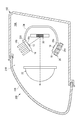
- FIG. 1 is a schematic sectional view of a vehicular lamp 100 according to an embodiment of the present invention.
- the vehicular lamp 100 includes a resin lamp body 102 having an open front surface, and an outer lens 104 formed of a translucent material and airtightly covering the front surface of the lamp body 102.
- a lamp unit 10 having a semiconductor light emitting element as a light source is housed in the configured lamp chamber 106.
- the lamp unit 10 includes an LED 12 as a first light source, a laser diode 14 as a second light source different from the LED 12, a micromirror array 20 as an optical member for controlling the light from the LED 12 and the laser diode 14, and a projection lens 22.
- the LED 12 is a light source having a higher output than the laser diode 14, and generates more heat than the laser diode 14.
- the LED 12 is arranged above the micro mirror array 20, and the laser diode 14 is arranged below the micro mirror array 20.
- the LED 12 and the laser diode 14 are configured so as not to be turned on at the same time.
- the micromirror array 20 is a light distribution device that distributes incident light.
- the micro mirror array 20 uses a MEMS (Micro Electro Mechanical System) mirror, a DMD (Digital Mirror Device) mirror, or the like, and is provided with a plurality of minute mirror elements that can be individually tilt-controlled. Further, instead of the micro mirror array 20, an LCOS device including a reflective liquid crystal element can be used.
- the light from the LED 12 and the light from the laser diode 14 are light distribution controlled by the common micromirror array 20.
- the micromirror array 20 By using the micromirror array 20 in common, it is possible to reduce the size and cost as compared with the case where the micromirror array is provided for each of the LED 12 and the laser diode 14.
- the projection lens 22 is a plano-convex aspherical lens having a convex front surface and a flat rear surface, and projects the light from the micromirror array 20 to the front of the lamp. According to the lamp unit 10 of the present embodiment, a desired light distribution pattern can be formed in front of the lamp by tilting each mirror element of the micro mirror array 20.
- the lamp unit 10 further includes an LED heat sink 16 that cools the LED 12, a laser heat sink 18 that cools the laser diode 14, a heat pipe 24 that connects the LED heat sink 16 and the laser heat sink 18, and an LED heat sink 16. And a fan 26 that blows the air.
- the LED heat sink 16 is formed of a metal having a high thermal conductivity such as aluminum, and has a flat plate-shaped base portion 16a, and a plurality of flat plate-shaped heat radiations provided upright on one main surface of the base portion 16a at a predetermined interval. And fins 16b.
- the LED 12 is arranged on the other main surface (the surface on the micromirror array 20 side) of the base portion 16a.
- the laser heat sink 18 is a flat heat sink formed of a metal having a high thermal conductivity such as aluminum. In this embodiment, no heat radiation fin is formed on the laser heat sink 18.
- the laser diode 14 is arranged on one main surface (the surface on the side of the micromirror array 20) of the laser heat sink 18.
- the LED heat sink 16 Since the LED heat sink 16 is provided with heat radiation fins, it has a higher heat radiation performance than the laser heat sink 18.
- the LED heat sink 16 having a relatively high heat dissipation performance is arranged for the LED 12 having a high output and a relatively large heat generation, and the heat dissipation property is relatively high for the laser diode 14 having a low output and a relatively small heat generation.
- An extremely low heat sink 18 for laser is arranged. The size of the laser heat sink 18 is smaller than that of the LED heat sink 16 because the heat radiation fins are not formed.
- One end of the heat pipe 24 is connected to the base portion 16a of the LED heat sink 16, and the other end is connected to the laser heat sink 18.
- the heat pipe 24 and the heat sink may be connected to each other by a method such as soldering, which causes less heat loss. Further, grease may be applied between the heat pipe 24 and the heat sink in order to enhance heat transfer.
- the fan 26 is an axial fan and has an intake port 26a and an exhaust port 26b.
- the fan 26 is arranged so that the exhaust port 26b faces the heat radiation fins 16b of the LED heat sink 16.
- the fan 26 is driven while at least one of the LED 12 and the laser diode 14 is on.
- the heat dissipation function of the vehicle lighting device 100 configured as described above will be described. As described above, the LED 12 and the laser diode 14 are configured so as not to be turned on at the same time.
- the heat generated from the LED 12 is transferred to the base portion 16a of the LED heat sink 16 and then transferred from the base portion 16a to the heat radiation fin 16b.
- the heat transmitted to the radiating fins 16b is radiated into the lamp chamber 106 by the air blown from the fan 26. Further, a part of the heat of the base portion 16 a is transferred from the base portion 16 a to the heat pipe 24, and then transferred to the laser heat sink 18 via the heat pipe 24.
- the heat transmitted to the laser heat sink 18 is radiated into the lamp chamber 106.
- the heat generated from the laser diode 14 is transferred to the laser heat sink 18 and radiated into the lamp chamber 106. Further, a part of the heat of the laser heat sink 18 is transferred from the laser heat sink 18 to the heat pipe 24, and then transferred to the LED heat sink 16 via the heat pipe 24. The heat transmitted to the LED heat sink 16 is radiated into the lamp chamber 106 by the air blown from the fan 26.
- the vehicular lamp 100 by connecting the LED heat sink 16 and the laser heat sink 18 with the heat pipe 24, heat generated from the light source that is turned on among the two light sources is generated. It is possible to dissipate heat not only from the heat sink connected to the light source that is on, but also from the heat sink connected to the light source that is off. That is, since the heat generated from one light source can be shared by the two heat sinks, the heat sink for LED 16 and the heat sink for laser can be compared with the case where the heat sink 24 for LED is not connected by the heat pipe 24. Since the heat sink 18 having a small size can be used, the lamp unit 10 can be downsized.
- part of the heat generated in the laser diode 14 can be released to the LED heat sink 16 by the heat pipe 24, so a fan is arranged on the laser heat sink 18 side. I haven't. Since the number of fans can be reduced as compared with the case where fans are provided for the respective heat sinks, it is possible to reduce the size and cost of the lamp unit 10.
- FIG. 2 is a schematic sectional view of a vehicular lamp 200 according to another embodiment of the present invention.
- the lamp unit 210 of the vehicle lamp 200 according to the present embodiment includes a Peltier element 220 arranged between the LED heat sink 16 and the heat pipe 24, and a current controller that controls a current supplied to the Peltier element 220 (FIG. 1 is different from the lamp unit 10 of the vehicle lamp 100 shown in FIG.
- the fan 26 is arranged so as to blow air to the laser heat sink 18. The fan 26 is driven while at least one of the LED 12 and the laser diode 14 is on.
- the Peltier element 220 is a plate-shaped semiconductor element that moves heat from one main surface to the other main surface by passing an electric current.
- the heat absorption surface and the heat dissipation surface are determined according to the direction of current flow.
- the base portion 16 a of the LED heat sink 16 is connected to one main surface of the Peltier element 220, and one end of the heat pipe 24 is connected to the other main surface of the Peltier element 220.
- the LED 12 and the laser diode 14 are configured not to be turned on at the same time.
- the heat generated from the LED 12 is transferred to the base portion 16a of the LED heat sink 16 and then transferred from the base portion 16a to the heat radiation fin 16b.
- the heat transmitted to the radiation fin 16b is radiated into the lamp chamber 106.
- the Peltier element 220 is supplied with current so as to absorb heat from the base portion 16 a of the LED heat sink 16 and radiate it to the heat pipe 24.
- a part of the heat of the base portion 16 a is transferred to the laser heat sink 18 via the heat pipe 24.
- the heat transmitted to the laser heat sink 18 is radiated into the lamp chamber 106 by the air blown from the fan 26.
- the heat generated from the laser diode 14 is transferred to the laser heat sink 18, and is radiated into the lamp chamber 106 by the air blown from the fan 26.
- the Peltier device 220 is supplied with current so as to absorb heat from the heat pipe 24 and radiate it to the base portion 16 a of the LED heat sink 16.
- Part of the heat of the laser heat sink 18 is transferred to the base portion 16 a of the LED heat sink 16 via the heat pipe 24.
- the heat transmitted to the base portion 16a is radiated from the heat radiation fins 16b into the lamp chamber 106.
- the Peltier element 220 is arranged between the LED heat sink 16 and the heat pipe 24, so that the heat sink can be provided between the heat sinks more than the vehicular lamp 100 shown in FIG. The heat transfer can be effectively performed.
- the LED heat sink 16 and the laser heat sink 18 having a smaller size can be used. It is possible to reduce the size of the unit 210.
- the heat of the LED heat sink 16 can be effectively transferred to the laser heat sink 18 and can be efficiently dissipated from the laser heat sink 18.
- no fan is arranged on the LED heat sink 16 side.
- efficient cooling can be performed using only one fan 26.
- the present invention can be used for vehicle lighting.
- 10,210 lamp unit 12 LED, 14 laser diode, 16 LED heat sink, 18 laser heat sink, 20 micro mirror array, 24 heat pipe, 26 fan, 100,200 vehicle lamp, 106 lamp room, 220 Peltier element.
Landscapes
- Engineering & Computer Science (AREA)
- General Engineering & Computer Science (AREA)
- Physics & Mathematics (AREA)
- Optics & Photonics (AREA)
- Microelectronics & Electronic Packaging (AREA)
- Non-Portable Lighting Devices Or Systems Thereof (AREA)
- Arrangement Of Elements, Cooling, Sealing, Or The Like Of Lighting Devices (AREA)
Abstract
車両用灯具100は、LED12と、レーザダイオード14と、LED12を冷却するLED用ヒートシンク16と、レーザダイオード14を冷却するレーザ用ヒートシンク18と、LED用ヒートシンク16とレーザ用ヒートシンク18を連結するヒートパイプ24とを備える。LED12とレーザダイオード14は、同時に点灯しないように構成される。
Description
本発明は、車両用灯具に関する。
従来、LED(Light Emitting Diode)等の半導体発光素子と、該半導体発光素子からの光を制御するマイクロミラーアレイ等の光学部材とを備えた車両用灯具が知られている(例えば特許文献1参照)。
LEDとレーザダイオードなど、異なる複数の光源からの光をマイクロミラーアレイで制御する場合がある。この場合、それぞれの光源に別々にヒートシンクとファンを設けると、灯具の構成が大型化する可能性がある。
本発明はこうした状況に鑑みてなされたものであり、その目的は、複数の光源を備える車両用灯具の小型化を図ることのできる技術を提供することにある。
上記課題を解決するために、本発明のある態様の車両用灯具は、第1光源と、第1光源と異なる第2光源と、第1光源を冷却する第1ヒートシンクと、第2光源を冷却する第2ヒートシンクと、第1ヒートシンクと第2ヒートシンクを連結するヒートパイプとを備える。第1光源と第2光源は、同時に点灯しないように構成される。
第1光源は、第2光源よりも高出力の光源であり、第1ヒートシンクは、第2ヒートシンクよりも放熱性能の高いヒートシンクであってもよい。
第1ヒートシンクとヒートパイプとの間に配置されたペルチェ素子をさらに備えてもよい。
ペルチェ素子は、第1光源が点灯しているときは、第1ヒートシンクから吸熱してヒートパイプに放熱し、第2光源が点灯しているときは、ヒートパイプから吸熱して第1ヒートシンクに放熱してもよい。
第2ヒートシンクに送風するファンをさらに備えてもよい。
本発明によれば、複数の光源を備える車両用灯具の小型化を図ることができる。
以下、図面を参照して本発明の実施形態に係る車両用灯具について詳細に説明する。なお、本明細書において「上」、「下」、「前」、「後」、「左」、「右」、「内」、「外」等の方向を表す用語が用いられる場合、それらは車両用灯具が車両に装着されたときの姿勢における方向を意味する。また、以下の実施形態では、同一または対応する構成要素については同じ符号を付し、重複する説明は適宜省略する。
図1は、本発明の実施形態に係る車両用灯具100の概略断面図である。図1に示すように、車両用灯具100は、前面が開放した樹脂製のランプボディ102と、透光性材料により形成され、ランプボディ102の前面を気密的に覆うアウターレンズ104とを含んで構成された灯室106内に、半導体発光素子を光源とする灯具ユニット10が収容された構成となっている。
灯具ユニット10は、第1光源としてのLED12と、LED12と異なる第2光源としてのレーザダイオード14と、LED12、レーザダイオード14からの光を制御する光学部材としてのマイクロミラーアレイ20と、投影レンズ22とを備える。
本実施形態において、LED12は、レーザダイオード14よりも高出力の光源であり、レーザダイオード14と比較して発熱が大きい。本実施形態では、図1に示すように、LED12はマイクロミラーアレイ20よりも上方に配置され、レーザダイオード14はマイクロミラーアレイ20よりも下方に配置されている。本実施形態では、LED12とレーザダイオード14は、同時に点灯しないように構成される。
マイクロミラーアレイ20は、入射した光を配光する配光デバイスである。マイクロミラーアレイ20は、MEMS(Micro Electro Mechanical System)ミラーやDMD(Digital Mirror Device)ミラーなどが用いられ、複数の微小なミラー素子が個別に傾動制御可能に設けられている。また、マイクロミラーアレイ20に代えて、反射型液晶素子からなるLCOSデバイスを使用することもできる。
本実施形態に係る車両用灯具100では、LED12からの光と、レーザダイオード14からの光は、共通のマイクロミラーアレイ20により配光制御される。マイクロミラーアレイ20を共通とすることにより、LED12およびレーザダイオード14のそれぞれにマイクロミラーアレイを設ける場合と比較して、小型化および低コスト化を図ることができる。
投影レンズ22は、前方側表面が凸面で後方側表面が平面の平凸非球面レンズからなり、マイクロミラーアレイ20からの光を灯具前方に投影する。本実施形態に係る灯具ユニット10によれば、マイクロミラーアレイ20の各ミラー素子を傾動制御することにより、灯具前方に所望の配光パターンを形成することができる。
灯具ユニット10はさらに、LED12を冷却するLED用ヒートシンク16と、レーザダイオード14を冷却するレーザ用ヒートシンク18と、LED用ヒートシンク16とレーザ用ヒートシンク18とを連結するヒートパイプ24と、LED用ヒートシンク16に送風するファン26とを備える。
LED用ヒートシンク16は、アルミ等の高熱伝導率の金属によって形成され、平板状のベース部16aと、ベース部16aの一方の主面上に所定の間隔で立設された複数の平板状の放熱フィン16bとから成る。ベース部16aの他方の主面(マイクロミラーアレイ20側の面)上にはLED12が配置される。
レーザ用ヒートシンク18は、アルミ等の高熱伝導率の金属によって形成された平板状のヒートシンクである。本実施形態では、レーザ用ヒートシンク18には放熱フィンは形成されていない。レーザ用ヒートシンク18の一方の主面(マイクロミラーアレイ20側の面)上にはレーザダイオード14が配置される。
LED用ヒートシンク16は、放熱フィンを備えているため、レーザ用ヒートシンク18よりも放熱性能が高い。本実施形態では、高出力で発熱が相対的に大きいLED12には放熱性能が相対的に高いLED用ヒートシンク16を配置し、低出力で発熱が相対的に小さいレーザダイオード14には放熱性が相対的に低いレーザ用ヒートシンク18を配置している。レーザ用ヒートシンク18は、放熱フィンが形成されていない分だけ、LED用ヒートシンク16よりもサイズが小さい。
ヒートパイプ24の一端は、LED用ヒートシンク16のベース部16aに接続され、その他端は、レーザ用ヒートシンク18に接続される。ヒートパイプ24とヒートシンクは、例えばハンダ付けなどの伝熱ロスの少ない方法で接続されてよい。また、伝熱性を高めるために、ヒートパイプ24とヒートシンクとの間にグリスが塗布されてもよい。
ファン26は、軸流ファンであり、吸気口26aおよび排気口26bを有する。ファン26は、排気口26bがLED用ヒートシンク16の放熱フィン16bに面するように配置される。ファン26は、少なくともLED12およびレーザダイオード14の一方が点灯している間は駆動される。
以上のように構成された車両用灯具100における放熱作用について説明する。上述したように、LED12とレーザダイオード14は、同時に点灯しないように構成される。
LED12が点灯し、レーザダイオード14が消灯しているとき、LED12から発生した熱は、LED用ヒートシンク16のベース部16aに伝熱され、ベース部16aから放熱フィン16bに伝熱される。放熱フィン16bに伝わった熱は、ファン26からの送風により灯室106内に放熱される。また、ベース部16aの熱の一部は、ベース部16aからヒートパイプ24に伝熱され、ヒートパイプ24を介してレーザ用ヒートシンク18に伝熱される。レーザ用ヒートシンク18に伝わった熱は、灯室106内に放熱される。
一方、LED12が消灯し、レーザダイオード14が点灯しているとき、レーザダイオード14から発生した熱は、レーザ用ヒートシンク18に伝熱され、灯室106内に放熱される。また、レーザ用ヒートシンク18の熱の一部は、レーザ用ヒートシンク18からヒートパイプ24に伝熱され、ヒートパイプ24を介してLED用ヒートシンク16に伝熱される。LED用ヒートシンク16に伝わった熱は、ファン26からの送風により灯室106内に放熱される。
このように、本実施形態に係る車両用灯具100においては、LED用ヒートシンク16とレーザ用ヒートシンク18をヒートパイプ24で連結したことにより、2つの光源のうち点灯している光源から発生した熱を、点灯している光源に接続されたヒートシンクだけでなく、消灯している光源に接続されたヒートシンクからも放熱することができる。すなわち、一方の光源から発生した熱を2つのヒートシンクで分担して放熱できるので、LED用ヒートシンク16とレーザ用ヒートシンク18をヒートパイプ24で連結しない場合と比較して、LED用ヒートシンク16およびレーザ用ヒートシンク18としてサイズの小さいものを用いることができるので、灯具ユニット10の小型化を図ることができる。
また、本実施形態に係る車両用灯具100においては、レーザダイオード14で発生した熱の一部をヒートパイプ24によってLED用ヒートシンク16に逃がすことができるので、レーザ用ヒートシンク18側にはファンを配置していない。それぞれのヒートシンクにファンを設ける場合と比較して、ファンの数を減らすことができるので、灯具ユニット10の小型化および低コスト化を図ることができる。
図2は、本発明の別の実施形態に係る車両用灯具200の概略断面図である。本実施形態に係る車両用灯具200の灯具ユニット210は、LED用ヒートシンク16とヒートパイプ24との間に配置されたペルチェ素子220と、ペルチェ素子220に供給する電流を制御する電流制御部(図示せず)を備える点が図1に示す車両用灯具100の灯具ユニット10と異なる。また、灯具ユニット210では、ファン26がレーザ用ヒートシンク18に送風するように配置されている。ファン26は、少なくともLED12およびレーザダイオード14の一方が点灯している間は駆動される。
ペルチェ素子220は、電流を流すことにより一方の主面から他方の主面に熱を移動させる板状の半導体素子である。ペルチェ素子220は、電流の流れる方向に応じて、吸熱面と放熱面が定まる。図2に示すように、ペルチェ素子220の一方の主面にはLED用ヒートシンク16のベース部16aが接続され、ペルチェ素子220の他方の主面にはヒートパイプ24の一端が接続されている。
以上のように構成された車両用灯具200における放熱作用について説明する。本実施形態に係る車両用灯具200においても、LED12とレーザダイオード14は、同時に点灯しないように構成される。
LED12が点灯し、レーザダイオード14が消灯しているとき、LED12から発生した熱は、LED用ヒートシンク16のベース部16aに伝熱され、ベース部16aから放熱フィン16bに伝熱される。放熱フィン16bに伝わった熱は、灯室106内に放熱される。このとき、ペルチェ素子220は、LED用ヒートシンク16のベース部16aから吸熱して、ヒートパイプ24に放熱するように電流が供給される。これにより、ベース部16aの熱の一部は、ヒートパイプ24を介してレーザ用ヒートシンク18に伝熱される。レーザ用ヒートシンク18に伝わった熱は、ファン26からの送風により灯室106内に放熱される。
一方、LED12が消灯し、レーザダイオード14が点灯しているとき、レーザダイオード14から発生した熱は、レーザ用ヒートシンク18に伝熱され、ファン26からの送風により灯室106内に放熱される。このとき、ペルチェ素子220は、ヒートパイプ24から吸熱して、LED用ヒートシンク16のベース部16aに放熱するように電流が供給される。レーザ用ヒートシンク18の熱の一部は、ヒートパイプ24を介してLED用ヒートシンク16のベース部16aに伝熱される。ベース部16aに伝わった熱は、放熱フィン16bから灯室106内に放熱される。
このように、本実施形態に係る車両用灯具200においては、LED用ヒートシンク16とヒートパイプ24との間にペルチェ素子220を配置したことにより、図1に示す車両用灯具100よりもヒートシンク間での熱の移動を効果的に行うことができる。
本実施形態においても、LED用ヒートシンク16とレーザ用ヒートシンク18をヒートパイプ24で連結しない場合と比較して、LED用ヒートシンク16およびレーザ用ヒートシンク18としてサイズの小さいものを用いることができるので、灯具ユニット210の小型化を図ることができる。
本実施形態では、ペルチェ素子220を用いることにより、LED用ヒートシンク16の熱をレーザ用ヒートシンク18に効果的に伝熱し、レーザ用ヒートシンク18から効率的に放熱できるので、ファン26をレーザ用ヒートシンク18側に配置し、LED用ヒートシンク16側にはファンを配置していない。このように本実施形態においても、1つのファン26のみを用いながらも、効率的な冷却を行うことができる。
以上、実施の形態をもとに本発明を説明した。これらの実施形態は例示であり、各構成要素や各処理プロセスの組合せにいろいろな変形例が可能なこと、またそうした変形例も本発明の範囲にあることは当業者に理解されるところである。
本発明は、車両用灯具に利用できる。
10,210 灯具ユニット、 12 LED、 14 レーザダイオード、 16 LED用ヒートシンク、 18 レーザ用ヒートシンク、 20 マイクロミラーアレイ、 24 ヒートパイプ、 26 ファン、 100,200 車両用灯具、 106 灯室、 220 ペルチェ素子。
Claims (8)
- 第1光源と、
前記第1光源と異なる第2光源と、
前記第1光源を冷却する第1ヒートシンクと、
前記第2光源を冷却する第2ヒートシンクと、
前記第1ヒートシンクと前記第2ヒートシンクを連結するヒートパイプと、
を備え、
前記第1光源と前記第2光源は、同時に点灯しないように構成されることを特徴とする車両用灯具。 - 前記第1光源は、前記第2光源よりも高出力の光源であり、
前記第1ヒートシンクは、前記第2ヒートシンクよりも放熱性能の高いヒートシンクであることを特徴とする請求項1に記載の車両用灯具。 - 前記第1ヒートシンクと前記ヒートパイプとの間に配置されたペルチェ素子をさらに備えることを特徴とする請求項2に記載の車両用灯具。
- 前記ペルチェ素子は、
前記第1光源が点灯しているときは、前記第1ヒートシンクから吸熱して前記ヒートパイプに放熱し、
前記第2光源が点灯しているときは、前記ヒートパイプから吸熱して前記第1ヒートシンクに放熱することを特徴とする請求項3に記載の車両用灯具。 - 前記第2ヒートシンクに送風するファンをさらに備えることを特徴とする請求項2から4のいずれかに記載の車両用灯具。
- 前記第1ヒートシンクは、平板状のベース部と、前記ベース部の一方の主面上に所定の間隔で立設された複数の放熱フィンとを含むヒートシンクであり、
前記第2ヒートシンクは、平板状のヒートシンクであることを特徴とする請求項2から5のいずれかに記載の車両用灯具。 - 前記第1光源は、LEDであり、
前記第2光源は、レーザダイオードであることを特徴とする請求項1から6のいずれかに記載の車両用灯具。 - 前記第1光源からの光と前記第2光源からの光を制御する共通のマイクロミラーアレイをさらに備えることを特徴とする請求項1から7のいずれかに記載の車両用灯具。
Priority Applications (1)
| Application Number | Priority Date | Filing Date | Title |
|---|---|---|---|
| JP2021501775A JPWO2020170738A1 (ja) | 2019-02-22 | 2020-01-29 | 車両用灯具 |
Applications Claiming Priority (2)
| Application Number | Priority Date | Filing Date | Title |
|---|---|---|---|
| JP2019030788 | 2019-02-22 | ||
| JP2019-030788 | 2019-02-22 |
Publications (1)
| Publication Number | Publication Date |
|---|---|
| WO2020170738A1 true WO2020170738A1 (ja) | 2020-08-27 |
Family
ID=72143764
Family Applications (1)
| Application Number | Title | Priority Date | Filing Date |
|---|---|---|---|
| PCT/JP2020/003141 Ceased WO2020170738A1 (ja) | 2019-02-22 | 2020-01-29 | 車両用灯具 |
Country Status (2)
| Country | Link |
|---|---|
| JP (1) | JPWO2020170738A1 (ja) |
| WO (1) | WO2020170738A1 (ja) |
Citations (2)
| Publication number | Priority date | Publication date | Assignee | Title |
|---|---|---|---|---|
| JP2006286395A (ja) * | 2005-03-31 | 2006-10-19 | Ichikoh Ind Ltd | 車両用灯具 |
| JP2008218157A (ja) * | 2007-03-02 | 2008-09-18 | Stanley Electric Co Ltd | 車両用前照灯 |
-
2020
- 2020-01-29 JP JP2021501775A patent/JPWO2020170738A1/ja active Pending
- 2020-01-29 WO PCT/JP2020/003141 patent/WO2020170738A1/ja not_active Ceased
Patent Citations (2)
| Publication number | Priority date | Publication date | Assignee | Title |
|---|---|---|---|---|
| JP2006286395A (ja) * | 2005-03-31 | 2006-10-19 | Ichikoh Ind Ltd | 車両用灯具 |
| JP2008218157A (ja) * | 2007-03-02 | 2008-09-18 | Stanley Electric Co Ltd | 車両用前照灯 |
Also Published As
| Publication number | Publication date |
|---|---|
| JPWO2020170738A1 (ja) | 2021-12-16 |
Similar Documents
| Publication | Publication Date | Title |
|---|---|---|
| US9297522B2 (en) | Lighting device | |
| US20130308104A1 (en) | Light source apparatus and image projection apparatus | |
| US20060193130A1 (en) | LED lighting system | |
| JP2011508372A5 (ja) | ||
| WO2009147800A1 (ja) | 車両用灯具 | |
| US10185210B2 (en) | Luminous light emitting device, light source unit and image projection system | |
| JP7176211B2 (ja) | 照明装置 | |
| EP2753877B1 (en) | Led cooling system | |
| CN105988267A (zh) | 散热装置、光源装置及具备该光源装置的投影装置 | |
| JP2021503158A (ja) | 空間的に制御可能なリフレクタ要素を備えた照明装置 | |
| CN209909794U (zh) | 冷却单元以及车辆用灯具 | |
| CN108427239B (zh) | 光源装置及投影装置 | |
| JPWO2019131054A1 (ja) | 灯具ユニット | |
| CN106051581A (zh) | 一种远近光合一的led照明模组 | |
| JP4463195B2 (ja) | 光源装置 | |
| JP7216558B2 (ja) | 車両用灯具 | |
| JP6801344B2 (ja) | 車両用灯具 | |
| WO2020170738A1 (ja) | 車両用灯具 | |
| TWM594106U (zh) | 燈具及燈具系統 | |
| CN113671779B (zh) | 光源装置及投影装置 | |
| JP2004182071A (ja) | 照明用灯具 | |
| JP5304572B2 (ja) | 発光モジュール及びこれを備えた照明器具 | |
| CN223486349U (zh) | 投影装置 | |
| JP7099900B2 (ja) | 車両用灯具 | |
| KR20200116780A (ko) | 광 발산각 제어를 위한 led광학계 |
Legal Events
| Date | Code | Title | Description |
|---|---|---|---|
| 121 | Ep: the epo has been informed by wipo that ep was designated in this application |
Ref document number: 20760134 Country of ref document: EP Kind code of ref document: A1 |
|
| ENP | Entry into the national phase |
Ref document number: 2021501775 Country of ref document: JP Kind code of ref document: A |
|
| NENP | Non-entry into the national phase |
Ref country code: DE |
|
| 122 | Ep: pct application non-entry in european phase |
Ref document number: 20760134 Country of ref document: EP Kind code of ref document: A1 |