WO2020170634A1 - ハイブリッド車両の制御装置 - Google Patents
ハイブリッド車両の制御装置 Download PDFInfo
- Publication number
- WO2020170634A1 WO2020170634A1 PCT/JP2020/000422 JP2020000422W WO2020170634A1 WO 2020170634 A1 WO2020170634 A1 WO 2020170634A1 JP 2020000422 W JP2020000422 W JP 2020000422W WO 2020170634 A1 WO2020170634 A1 WO 2020170634A1
- Authority
- WO
- WIPO (PCT)
- Prior art keywords
- compression ratio
- engine
- hybrid vehicle
- control device
- internal combustion
- Prior art date
- Legal status (The legal status is an assumption and is not a legal conclusion. Google has not performed a legal analysis and makes no representation as to the accuracy of the status listed.)
- Ceased
Links
Images


Classifications
-
- B—PERFORMING OPERATIONS; TRANSPORTING
- B60—VEHICLES IN GENERAL
- B60K—ARRANGEMENT OR MOUNTING OF PROPULSION UNITS OR OF TRANSMISSIONS IN VEHICLES; ARRANGEMENT OR MOUNTING OF PLURAL DIVERSE PRIME-MOVERS IN VEHICLES; AUXILIARY DRIVES FOR VEHICLES; INSTRUMENTATION OR DASHBOARDS FOR VEHICLES; ARRANGEMENTS IN CONNECTION WITH COOLING, AIR INTAKE, GAS EXHAUST OR FUEL SUPPLY OF PROPULSION UNITS IN VEHICLES
- B60K6/00—Arrangement or mounting of plural diverse prime-movers for mutual or common propulsion, e.g. hybrid propulsion systems comprising electric motors and internal combustion engines
- B60K6/20—Arrangement or mounting of plural diverse prime-movers for mutual or common propulsion, e.g. hybrid propulsion systems comprising electric motors and internal combustion engines the prime-movers consisting of electric motors and internal combustion engines, e.g. HEVs
- B60K6/22—Arrangement or mounting of plural diverse prime-movers for mutual or common propulsion, e.g. hybrid propulsion systems comprising electric motors and internal combustion engines the prime-movers consisting of electric motors and internal combustion engines, e.g. HEVs characterised by apparatus, components or means specially adapted for HEVs
- B60K6/24—Arrangement or mounting of plural diverse prime-movers for mutual or common propulsion, e.g. hybrid propulsion systems comprising electric motors and internal combustion engines the prime-movers consisting of electric motors and internal combustion engines, e.g. HEVs characterised by apparatus, components or means specially adapted for HEVs characterised by the combustion engines
-
- B—PERFORMING OPERATIONS; TRANSPORTING
- B60—VEHICLES IN GENERAL
- B60K—ARRANGEMENT OR MOUNTING OF PROPULSION UNITS OR OF TRANSMISSIONS IN VEHICLES; ARRANGEMENT OR MOUNTING OF PLURAL DIVERSE PRIME-MOVERS IN VEHICLES; AUXILIARY DRIVES FOR VEHICLES; INSTRUMENTATION OR DASHBOARDS FOR VEHICLES; ARRANGEMENTS IN CONNECTION WITH COOLING, AIR INTAKE, GAS EXHAUST OR FUEL SUPPLY OF PROPULSION UNITS IN VEHICLES
- B60K6/00—Arrangement or mounting of plural diverse prime-movers for mutual or common propulsion, e.g. hybrid propulsion systems comprising electric motors and internal combustion engines
- B60K6/20—Arrangement or mounting of plural diverse prime-movers for mutual or common propulsion, e.g. hybrid propulsion systems comprising electric motors and internal combustion engines the prime-movers consisting of electric motors and internal combustion engines, e.g. HEVs
- B60K6/42—Arrangement or mounting of plural diverse prime-movers for mutual or common propulsion, e.g. hybrid propulsion systems comprising electric motors and internal combustion engines the prime-movers consisting of electric motors and internal combustion engines, e.g. HEVs characterised by the architecture of the hybrid electric vehicle
- B60K6/46—Series type
-
- B—PERFORMING OPERATIONS; TRANSPORTING
- B60—VEHICLES IN GENERAL
- B60L—PROPULSION OF ELECTRICALLY-PROPELLED VEHICLES; SUPPLYING ELECTRIC POWER FOR AUXILIARY EQUIPMENT OF ELECTRICALLY-PROPELLED VEHICLES; ELECTRODYNAMIC BRAKE SYSTEMS FOR VEHICLES IN GENERAL; MAGNETIC SUSPENSION OR LEVITATION FOR VEHICLES; MONITORING OPERATING VARIABLES OF ELECTRICALLY-PROPELLED VEHICLES; ELECTRIC SAFETY DEVICES FOR ELECTRICALLY-PROPELLED VEHICLES
- B60L50/00—Electric propulsion with power supplied within the vehicle
- B60L50/10—Electric propulsion with power supplied within the vehicle using propulsion power supplied by engine-driven generators, e.g. generators driven by combustion engines
- B60L50/15—Electric propulsion with power supplied within the vehicle using propulsion power supplied by engine-driven generators, e.g. generators driven by combustion engines with additional electric power supply
-
- B—PERFORMING OPERATIONS; TRANSPORTING
- B60—VEHICLES IN GENERAL
- B60W—CONJOINT CONTROL OF VEHICLE SUB-UNITS OF DIFFERENT TYPE OR DIFFERENT FUNCTION; CONTROL SYSTEMS SPECIALLY ADAPTED FOR HYBRID VEHICLES; ROAD VEHICLE DRIVE CONTROL SYSTEMS FOR PURPOSES NOT RELATED TO THE CONTROL OF A PARTICULAR SUB-UNIT
- B60W10/00—Conjoint control of vehicle sub-units of different type or different function
- B60W10/04—Conjoint control of vehicle sub-units of different type or different function including control of propulsion units
- B60W10/06—Conjoint control of vehicle sub-units of different type or different function including control of propulsion units including control of combustion engines
-
- B—PERFORMING OPERATIONS; TRANSPORTING
- B60—VEHICLES IN GENERAL
- B60W—CONJOINT CONTROL OF VEHICLE SUB-UNITS OF DIFFERENT TYPE OR DIFFERENT FUNCTION; CONTROL SYSTEMS SPECIALLY ADAPTED FOR HYBRID VEHICLES; ROAD VEHICLE DRIVE CONTROL SYSTEMS FOR PURPOSES NOT RELATED TO THE CONTROL OF A PARTICULAR SUB-UNIT
- B60W10/00—Conjoint control of vehicle sub-units of different type or different function
- B60W10/04—Conjoint control of vehicle sub-units of different type or different function including control of propulsion units
- B60W10/08—Conjoint control of vehicle sub-units of different type or different function including control of propulsion units including control of electric propulsion units, e.g. motors or generators
-
- B—PERFORMING OPERATIONS; TRANSPORTING
- B60—VEHICLES IN GENERAL
- B60W—CONJOINT CONTROL OF VEHICLE SUB-UNITS OF DIFFERENT TYPE OR DIFFERENT FUNCTION; CONTROL SYSTEMS SPECIALLY ADAPTED FOR HYBRID VEHICLES; ROAD VEHICLE DRIVE CONTROL SYSTEMS FOR PURPOSES NOT RELATED TO THE CONTROL OF A PARTICULAR SUB-UNIT
- B60W20/00—Control systems specially adapted for hybrid vehicles
-
- F—MECHANICAL ENGINEERING; LIGHTING; HEATING; WEAPONS; BLASTING
- F02—COMBUSTION ENGINES; HOT-GAS OR COMBUSTION-PRODUCT ENGINE PLANTS
- F02B—INTERNAL-COMBUSTION PISTON ENGINES; COMBUSTION ENGINES IN GENERAL
- F02B75/00—Other engines
- F02B75/04—Engines with variable distances between pistons at top dead-centre positions and cylinder heads
-
- F—MECHANICAL ENGINEERING; LIGHTING; HEATING; WEAPONS; BLASTING
- F02—COMBUSTION ENGINES; HOT-GAS OR COMBUSTION-PRODUCT ENGINE PLANTS
- F02B—INTERNAL-COMBUSTION PISTON ENGINES; COMBUSTION ENGINES IN GENERAL
- F02B75/00—Other engines
- F02B75/32—Engines characterised by connections between pistons and main shafts and not specific to preceding main groups
-
- F—MECHANICAL ENGINEERING; LIGHTING; HEATING; WEAPONS; BLASTING
- F02—COMBUSTION ENGINES; HOT-GAS OR COMBUSTION-PRODUCT ENGINE PLANTS
- F02D—CONTROLLING COMBUSTION ENGINES
- F02D15/00—Varying compression ratio
- F02D15/02—Varying compression ratio by alteration or displacement of piston stroke
-
- F—MECHANICAL ENGINEERING; LIGHTING; HEATING; WEAPONS; BLASTING
- F02—COMBUSTION ENGINES; HOT-GAS OR COMBUSTION-PRODUCT ENGINE PLANTS
- F02D—CONTROLLING COMBUSTION ENGINES
- F02D17/00—Controlling engines by cutting out individual cylinders; Rendering engines inoperative or idling
-
- F—MECHANICAL ENGINEERING; LIGHTING; HEATING; WEAPONS; BLASTING
- F02—COMBUSTION ENGINES; HOT-GAS OR COMBUSTION-PRODUCT ENGINE PLANTS
- F02D—CONTROLLING COMBUSTION ENGINES
- F02D29/00—Controlling engines, such controlling being peculiar to the devices driven thereby, the devices being other than parts or accessories essential to engine operation, e.g. controlling of engines by signals external thereto
- F02D29/02—Controlling engines, such controlling being peculiar to the devices driven thereby, the devices being other than parts or accessories essential to engine operation, e.g. controlling of engines by signals external thereto peculiar to engines driving vehicles; peculiar to engines driving variable pitch propellers
-
- F—MECHANICAL ENGINEERING; LIGHTING; HEATING; WEAPONS; BLASTING
- F02—COMBUSTION ENGINES; HOT-GAS OR COMBUSTION-PRODUCT ENGINE PLANTS
- F02D—CONTROLLING COMBUSTION ENGINES
- F02D29/00—Controlling engines, such controlling being peculiar to the devices driven thereby, the devices being other than parts or accessories essential to engine operation, e.g. controlling of engines by signals external thereto
- F02D29/06—Controlling engines, such controlling being peculiar to the devices driven thereby, the devices being other than parts or accessories essential to engine operation, e.g. controlling of engines by signals external thereto peculiar to engines driving electric generators
-
- Y—GENERAL TAGGING OF NEW TECHNOLOGICAL DEVELOPMENTS; GENERAL TAGGING OF CROSS-SECTIONAL TECHNOLOGIES SPANNING OVER SEVERAL SECTIONS OF THE IPC; TECHNICAL SUBJECTS COVERED BY FORMER USPC CROSS-REFERENCE ART COLLECTIONS [XRACs] AND DIGESTS
- Y02—TECHNOLOGIES OR APPLICATIONS FOR MITIGATION OR ADAPTATION AGAINST CLIMATE CHANGE
- Y02T—CLIMATE CHANGE MITIGATION TECHNOLOGIES RELATED TO TRANSPORTATION
- Y02T10/00—Road transport of goods or passengers
- Y02T10/60—Other road transportation technologies with climate change mitigation effect
- Y02T10/62—Hybrid vehicles
-
- Y—GENERAL TAGGING OF NEW TECHNOLOGICAL DEVELOPMENTS; GENERAL TAGGING OF CROSS-SECTIONAL TECHNOLOGIES SPANNING OVER SEVERAL SECTIONS OF THE IPC; TECHNICAL SUBJECTS COVERED BY FORMER USPC CROSS-REFERENCE ART COLLECTIONS [XRACs] AND DIGESTS
- Y02—TECHNOLOGIES OR APPLICATIONS FOR MITIGATION OR ADAPTATION AGAINST CLIMATE CHANGE
- Y02T—CLIMATE CHANGE MITIGATION TECHNOLOGIES RELATED TO TRANSPORTATION
- Y02T10/00—Road transport of goods or passengers
- Y02T10/60—Other road transportation technologies with climate change mitigation effect
- Y02T10/70—Energy storage systems for electromobility, e.g. batteries
-
- Y—GENERAL TAGGING OF NEW TECHNOLOGICAL DEVELOPMENTS; GENERAL TAGGING OF CROSS-SECTIONAL TECHNOLOGIES SPANNING OVER SEVERAL SECTIONS OF THE IPC; TECHNICAL SUBJECTS COVERED BY FORMER USPC CROSS-REFERENCE ART COLLECTIONS [XRACs] AND DIGESTS
- Y02—TECHNOLOGIES OR APPLICATIONS FOR MITIGATION OR ADAPTATION AGAINST CLIMATE CHANGE
- Y02T—CLIMATE CHANGE MITIGATION TECHNOLOGIES RELATED TO TRANSPORTATION
- Y02T10/00—Road transport of goods or passengers
- Y02T10/60—Other road transportation technologies with climate change mitigation effect
- Y02T10/7072—Electromobility specific charging systems or methods for batteries, ultracapacitors, supercapacitors or double-layer capacitors
-
- Y—GENERAL TAGGING OF NEW TECHNOLOGICAL DEVELOPMENTS; GENERAL TAGGING OF CROSS-SECTIONAL TECHNOLOGIES SPANNING OVER SEVERAL SECTIONS OF THE IPC; TECHNICAL SUBJECTS COVERED BY FORMER USPC CROSS-REFERENCE ART COLLECTIONS [XRACs] AND DIGESTS
- Y02—TECHNOLOGIES OR APPLICATIONS FOR MITIGATION OR ADAPTATION AGAINST CLIMATE CHANGE
- Y02T—CLIMATE CHANGE MITIGATION TECHNOLOGIES RELATED TO TRANSPORTATION
- Y02T10/00—Road transport of goods or passengers
- Y02T10/60—Other road transportation technologies with climate change mitigation effect
- Y02T10/72—Electric energy management in electromobility
Definitions
- the present invention relates to a control device for a hybrid vehicle.
- Patent Document 1 discloses a variable compression ratio mechanism capable of continuously changing an engine compression ratio of an internal combustion engine by changing a stroke characteristic of a piston via a multi-link type piston-crank mechanism by an actuator having an electric motor. Is disclosed.
- variable compression ratio mechanism When the variable compression ratio mechanism is applied to a series hybrid vehicle in which a motor is used as a vehicle drive source and an internal combustion engine is used only for power generation, there is a need to reduce the required output of the actuator of the variable compression ratio mechanism. ..
- One of the objects of the present invention is to provide a control device for a hybrid vehicle that can reduce the required output of the actuator of the variable compression ratio mechanism.
- a hybrid vehicle control device includes a first step of stopping or decelerating the internal combustion engine when the drive motor and the internal combustion engine are being driven and the engine compression ratio is the second compression ratio. During or after the first step, there is a second step of changing the engine compression ratio from the second compression ratio to the first compression ratio, and a third step of driving the internal combustion engine after the second step.
- the required output of the actuator can be reduced.
- FIG. 3 is a configuration diagram of a drive system of the hybrid vehicle of Embodiment 1.
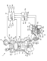
- FIG. 1 is a configuration diagram of an engine 1 of Embodiment 1.
- FIG. 3 is a schematic diagram of a multi-link mechanism 10 of Embodiment 1.
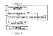
- FIG. 3 is a flowchart showing a flow of engine control and variable compression ratio control processing of the first embodiment.
- FIG. 6 is a characteristic diagram of a load torque and a link reduction ratio of the second control shaft 10e with respect to an angle (engine compression ratio) of the first control shaft 10a in the variable compression ratio mechanism 12.
- 3 is a time chart showing the operation of engine control and variable compression ratio control of the first embodiment.
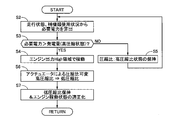
- 9 is a flowchart showing a flow of engine control and variable compression ratio control processing of the second embodiment.
- 9 is a flowchart showing a flow of engine control and variable compression ratio control processing according to the third embodiment.
- 6 is a configuration diagram of an engine 1 of Embodiment 4.
- FIG. 4 is a configuration
- FIG. 1 is a configuration diagram of a drive system of the hybrid vehicle of the first embodiment.
- the hybrid vehicle of the first embodiment is a series-type hybrid vehicle in which a motor generator (driving motor) 5 is used as a vehicle drive source and the engine 1 (internal combustion engine) is used only for power generation.
- the engine 1 drives the generator 2, and the electric power generated by the generator 2 is stored in the battery 4 via the inverter 3.
- the motor generator 5 is a vehicle drive source, and drives the drive wheels 6 with electric power supplied from the battery 4 via the inverter 3.
- the MG control unit 17 receives signals from respective sensors such as an accelerator opening sensor 18 and a vehicle speed sensor 19.
- the MG control unit 17 calculates the target MG torque of the motor generator 5 based on the detection signal of each sensor, and supplies the electric power to the motor generator 5 via the inverter 3 so that the actual motor torque becomes the target MG torque. ..
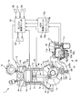
- FIG. 2 is a configuration diagram of the engine 1 of the first embodiment.
- the engine 1 includes a cylinder block 1a, a piston 1c provided in a cylinder bore 1b formed in the cylinder block 1a, a cylinder head 1f having an intake port 1d and an exhaust port 1e, an intake port 1d, and an opening of an exhaust port 1e.
- Each cylinder has a pair of intake valves 1g, 1g and exhaust valves 1h, 1h whose ends are opened and closed.
- the piston 1c is connected to the crankshaft 1m via a connecting rod 1k including a lower link 1i and an upper link 1j.
- a combustion chamber 1n is formed between the crown surface of the piston 1c and the lower surface of the cylinder head 1f.
- An ignition plug 1o is provided at approximately the center of the cylinder head 1f forming the combustion chamber 1n.
- the high voltage is supplied from the ignition coil 7 to the spark plug 1o to cause spark discharge to ignite and burn the air-fuel mixture, and the ignition timing is controlled by the high voltage supply timing from the ignition coil 7.
- the engine 1 has a variable valve timing mechanism (Valve Timing Control System, hereinafter referred to as VTC) 8 and a variable compression ratio mechanism (Variable Compression Ratio, hereinafter referred to as VCR) 9.
- VTC 8 has a variable phase with respect to the crankshaft 1m during the opening period of the intake valves 1g, 1g.
- the VTC8 changes the phase (control amount) of the intake camshaft 1p with respect to the crankshaft 1m to continuously advance and retard the central phase of the operating angle while keeping the operating angle of the intake valves 1g, 1g constant. It is a horning mechanism.
- the VTC8 for example, use an electric variable valve timing mechanism that adjusts the relative rotation phase angle of the intake camshaft 1p with respect to the crankshaft 1m by an electric motor, as disclosed in JP 2013-036391A. You can
- the VCR 9 makes the engine compression ratio variable by changing the top dead center position (combustion chamber volume) of the piston 1c.
- the VCR 9 is a mechanism that makes the engine compression ratio of the engine 1 variable by changing the position of the top dead center TDC of the piston 1c by the structure disclosed in JP 2011-169251 A, for example.
- An example of the structure of VCR9 will be described below.
- the crankshaft 1m has a plurality of journal portions 1q and a crank pin portion 1r, and the journal portion 1q is rotatably supported by the main bearing of the cylinder block 1a.
- the crank pin portion 1r is eccentric from the journal portion 1q, and the lower link 1i is rotatably connected thereto.
- the lower link 1i is divided into two parts, and the crank pin portion 1r is fitted in a connecting hole provided at the substantially center.
- the upper end side of the upper link 1j is rotatably connected to the piston 1c by a piston pin 1s.
- the lower link 1i is rotatably connected to the lower end side of the upper link 1j by a connecting pin 1t.
- An upper end of the first control link 1v is rotatably connected to the lower link 1i via a connecting pin 1u.
- the lower end of the first control link 1v is connected to the multiple link mechanism 10 of the variable compression ratio mechanism 12.
- the variable compression ratio mechanism 12 has a multi-link mechanism 10 and an actuator 11.
- the multi-link mechanism 10 has a first control shaft 10a, a first arm portion 10b, a second control link 10c, an arm link 10d and a second control shaft 10e.
- the first control shaft 10a is connected to the lower end of the first control link 1v and is rotatably supported by the cylinder block 1a.
- One end side of the first arm portion 10b is rotatably connected to the first control shaft 10a.
- the other end of the first arm portion 10b is rotatably connected to one end of the second control link 10c by a connecting pin 10f.
- the other end of the second control link 10c is rotatably connected to one end of the arm link 10d by a connecting pin 10g.
- the other end of the arm link 10d is connected to the second control shaft 10e.
- a part of the second control link 10c, the arm link 10d, and the second control shaft 10e are rotatably accommodated in the housing 11a of the actuator 11.
- the housing 11a is attached to the cylinder block 1a.
- the actuator 11 has an electric motor 11b.
- the electric motor 11b is, for example, a DC brushless motor.
- the actuator 11 changes the angle (rotation angle) of the second control shaft 10e by decelerating the rotational speed of the electric motor 11b by a wave gear reducer (not shown) and transmitting the reduced speed to the second control shaft 10e.
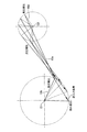
- FIG. 3 is a schematic diagram of the multi-link mechanism 10. As shown in FIG. 3, when the second control shaft 10e rotates about the rotation axis O2 and the angle of the second control shaft 10e is changed, The attitude of the control link 10c changes, the first control shaft 10a rotates around the rotation axis O1, and the position of the lower end of the first control link 1v is changed.
- the connecting pin 10f is always located on the same side as the second control shaft 10e with respect to the central axis L1 of the first control link 1v.
- variable range of the engine compression ratio that is, in the range from the minimum compression ratio (second compression ratio) to the maximum compression ratio (first compression ratio). That is, the position of the piston 1c (combustion chamber volume) at the top dead center TDC changes according to the angle (rotation angle) of the first control shaft 10a, and the engine compression ratio of the engine 1 changes.
- the minimum compression ratio and the maximum compression ratio are also simply referred to as high compression ratio and low compression ratio.
- the second control link 10c has a direction indicated by an arrow in FIG. 3, that is, an angle of the first control shaft 10a, due to the explosive force in the combustion stroke of the engine 1.
- a load torque reverse input torque that rotates from the side of the angle corresponding to the high compression ratio to the side of the angle corresponding to the low compression ratio acts.
- the ignition coil 7 and the fuel injection valve 13 for injecting fuel into the intake port 1d are controlled by the engine control unit 14, the VCR 9 is controlled by the VCR control unit (control device) 15, and the VTC 8 is controlled by the VTC control unit (not shown). Controlled.
- the VTC control unit calculates and outputs the operation amount of the VTC8 actuator so that the relative rotation angle of the intake camshaft 1p with respect to the crankshaft 1m approaches the target phase conversion angle input from the engine control unit 14. Perform timing feedback control.
- the engine control unit 14, the VCR control unit 15, the VTC control unit and the MG control unit 17 each have a microcomputer including a CPU, a memory, etc., and are communicably connected to each other by CAN (Controller Area Network) communication. ..
- the engine control unit 14 calculates the target compression ratio of the VCR 9 and the target phase conversion angle (target advance value) of the VTC 8 based on the operating state of the engine 1, and directs the target compression ratio data to the VCR control unit 15.
- the target phase angle conversion angle data is sent to the VTC control unit.
- the VCR control unit 15 receives the data of the target compression ratio from the engine control unit 14 (in other words, the data of the target angle of the first control shaft 10a) and the angle of the first control shaft 10a (that is, the data of the target angle). For example, the output signal of the angle sensor 16 for detecting the actual compression ratio) is input. The VCR control unit 15 calculates the operation amount of the actuator 11 so that the angle of the first control shaft 10a detected by the angle sensor 16 approaches the target angle corresponding to the target compression ratio, and outputs the compression ratio feedback control. Carry out.
- the VCR control unit 15 outputs information on the angle of the first control shaft 10a detected based on the output of the angle sensor 16 (in other words, information on the actual compression ratio) to the engine control unit 14.
- the engine control unit 14 receives signals from the crank angle sensor 20, the cam angle sensor 21, the air flow sensor 22, the water temperature sensor 23, the air-fuel ratio sensor 24, the knock sensor 25, and the like, as well as CAN communication.
- the target MG torque and the usage status of auxiliary equipment such as an air conditioner are input via this.
- the engine control unit 14 calculates the fuel supply amount to the engine 1 (fuel injection amount of the fuel injection valve), the ignition timing by the ignition plug 1o, etc. based on the detection signals of the above-mentioned sensors, etc., and outputs the injection pulse to the fuel injection valve.
- the engine control unit 14 operates the engine 1 in a high output (high rotation) region (engine output High region) in response to a request from the VCR control unit 15, and when the required power is relatively low, the engine 1 Is operated or stopped (engine stopped) in a low output (low rotation) area (for example, engine output low area such as idle rotation).
- FIG. 4 is a flowchart showing a flow of engine control and variable compression ratio control processing of the first embodiment. This process is executed during the startup of the vehicle.
- step S1 the VCR control unit 15 drives the actuator 11 so that the engine compression ratio becomes a high compression ratio.
- step S2 the required power acquisition unit 15a of the VCR control unit 15 calculates the required power of the vehicle from the running state and the usage status of the auxiliary machinery. The VCR control unit 15 may calculate the required power.
- step S3 the generated power acquisition unit 15b of the VCR control unit 15 calculates the power generation amount of the generator 2 in the high compression ratio state, and the determination unit 15c of the VCR control unit 15 calculates the required power calculated in step S2. It is determined whether it is larger than the generated power generation amount. If YES, the process proceeds to step S4, and if NO, the process proceeds to step S5.
- step S4 the determination unit 15c of the VCR control unit 15 increases the engine output and outputs a request to operate the engine 1 in the engine output high region to the engine control unit 14 (fourth step).
- step S5 the VCR control unit 15 drives the actuator 11 so that the engine compression ratio maintains a high compression ratio.
- step S6 the VCR control unit 15 drives the actuator 11 so that the engine compression ratio changes from the high compression ratio to the low compression ratio.
- the switching of the engine compression ratio may be started before the engine output reaches the engine output High region, or may be started after the engine output reaches the engine output High region.
- step S7 the VCR control unit 15 drives the actuator 11 so that the engine compression ratio maintains a low compression ratio.
- the engine control unit 14 also optimizes the operating state of the engine 1.
- step S8 the required electric power acquisition unit 15a of the VCR control unit 15 calculates the required electric power of the vehicle from the traveling state and the auxiliary equipment usage state.
- step S9 the generated power acquisition unit 15b of the VCR control unit 15 calculates the amount of power generated by the generator 2 in the high compression ratio state, and the determination unit 15c of the VCR control unit 15 calculates the required power calculated in step S2. It is determined whether it is larger than the generated power generation amount. If YES, the process proceeds to step S10, and if NO, the process proceeds to step S11.
- step S10 the determination unit 15c of the VCR control unit 15 requests that the engine output be reduced (decelerated) to operate the engine 1 in the engine output Low region, or the fuel ignition to the engine 1 is stopped to stop the engine 1.
- a request to perform is output to the engine control unit 14 (first step).
- step S11 the VCR control unit 15 drives the actuator 11 so that the engine compression ratio maintains a low compression ratio.
- step S12 the VCR control unit 15 drives the actuator 11 so that the engine compression ratio changes from the low compression ratio to the high compression ratio (second step).
- the switching of the engine compression ratio may be started before the engine output reaches the engine output Low region, or may be started after the engine output reaches the engine output Low region.
- step S10 when the request to stop the engine 1 is output in S10, it may be after the fuel ignition to the engine 1 is stopped.
- step S13 the VCR control unit 15 drives the actuator 11 so that the engine compression ratio maintains a high compression ratio.
- the engine control unit 14 also optimizes the operating state of the engine 1.
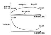
- FIG. 5 is a characteristic diagram of the load torque and the link reduction ratio of the second control shaft 10e with respect to the angle (engine compression ratio) of the first control shaft 10a in the variable compression ratio mechanism 12.
- the load torque acting on the second control shaft 10e changes in the range from the minimum load torque to the maximum load torque according to the stroke of the engine 1, and becomes maximum in the combustion stroke.
- the maximum load torque received by the second control shaft 10e takes a minimum value at a low compression ratio, increases from the low compression ratio to the high compression side, and is between the low compression ratio and the high compression ratio. It has a characteristic that the maximum load point is reached at an intermediate compression ratio of, and the value decreases from the maximum load point toward the high compression side.
- the link reduction ratio has a characteristic that it decreases from the low compression ratio toward the high compression side, becomes the lowest at an intermediate compression ratio between the low compression ratio and the high compression ratio, and rises toward the high compression side. ..
- variable compression ratio mechanism is mounted on a vehicle using an engine as a vehicle drive source.
- this variable compression ratio mechanism is applied to a series hybrid vehicle in which a motor is used as a vehicle drive source and an engine is used only for power generation, there are the following problems.
- the engine compression ratio is continuously changed in the range from the low compression ratio to the high compression ratio based on the output torque and the rotation speed of the engine with reference to a predetermined map. Therefore, the output of the electric motor needs to be determined in accordance with the load torque at the maximum load point, resulting in a large motor size.
- the changing speed of the engine compression ratio is higher, but the electric motor needs to operate against the load torque at the maximum load point. Therefore, responsiveness is lowered and power consumption is increased.
- the engine compression ratio of the engine 1 after the engine compression ratio of the engine 1 is started in the high compression ratio state, when the required power of the vehicle including the running state and the auxiliary machines exceeds the power generation amount in the high compression ratio state, That is, when the electric power is in a shortage state or when the engine is out of the operating region with high thermal efficiency in the high compression state, the engine output is increased and the engine compression ratio is switched from the high compression ratio to the low compression ratio.
- the required power of the vehicle is lower than the power generation amount in the high compression ratio state, that is, when the power generation amount is excessive, the engine output is reduced and the engine compression ratio is changed from the low compression ratio to the high compression ratio. Switch.
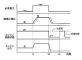
- FIG. 6 is a time chart showing the operation of the engine control and the variable compression ratio control of the first embodiment.
- the required electric power of the vehicle is lower than the power generation amount of the generator 2 in the high compression ratio state of the engine 1, so the engine control unit 14 operates the engine 1 in the engine output Low region. ..
- the VCR control unit 15 drives the actuator 11 and maintains the engine compression ratio at a high compression ratio.
- the power generation amount exceeds the required power, the engine 1 is operated at a low rotation speed and a rotation speed with high thermal efficiency, and the engine compression ratio is maintained at a high compression ratio, so that the fuel consumption can be improved.
- the engine control unit 14 increases the engine output and operates the engine 1 in the engine output high region.
- the VCR control unit 15 drives the actuator 11 to switch the engine compression ratio from the high compression ratio to the low compression ratio.
- the actuator 11 causes the second control shaft to move.
- the direction of the torque applied to 10e matches the direction of the reverse input torque. Therefore, the reverse input torque acts as an assist torque, and the changing speed of the engine compression ratio can be improved.
- the engine compression ratio can be quickly shifted to the low compression ratio, and the amount of power generation can be increased early.
- the engine compression ratio may be changed from the high compression ratio to the low compression ratio after the engine output is increased.
- the required output of the actuator 11 can be reduced as compared with the case where the engine compression ratio is changed while the engine output is increasing.
- the required electric power of the vehicle is reduced and is lower than the power generation amount of the generator 2 in the high compression ratio state of the engine 1, so the engine control unit 14 stops the engine 1.
- the VCR control unit 15 drives the actuator 11 to switch the engine compression ratio from the low compression ratio to the high compression ratio.
- the reverse input torque becomes zero by setting the engine output to zero.
- the required output of the actuator 11 can be reduced, and the actuator 11 (electric motor 11b) can be downsized.
- the fuel consumption of the engine 1 can be reduced as the high compression ratio state continues longer.
- the engine compression ratio may be changed from the low compression ratio to the high compression ratio while the engine output is decreasing.
- the required output of the actuator 11 can be reduced as compared with the case where the engine compression ratio is changed when the engine output decreases.
- the engine 1 is restarted based on the optimization of the operating state of the engine 1 and operates in the engine output Low region.
- a motor generator 5 as a vehicle drive source, a generator 2 that can supply electric power to the motor generator 5, an engine 1 that drives the generator 2, a variable compression ratio mechanism 12, and a multi-link mechanism 10.
- the actuator 11, the multi-link mechanism 10 is connected to the engine 1, and the actuator 11 can change the engine compression ratio of the engine 1 by changing the posture of the multi-link mechanism 10.
- a motor generator 5 When the engine compression ratio is the second compression ratio while the engine 1 is being driven, the engine compression ratio is changed between the first step (S10) of stopping or decelerating the engine 1 and the first step or after the first step.
- the method includes a second step (S12) of changing from the second compression ratio to the first compression ratio, and a third step (S13) of driving the engine 1 after the second step.
- the actuator 11 (electric motor 11b) can be downsized and the power consumption can be suppressed.
- the first compression ratio is higher than the second compression ratio. That is, when increasing the engine compression ratio, the engine output is reduced.
- the engine compression ratio is to be lowered, that is, if the engine is to be shifted to a high rotation speed, a power generation amount is required, and if the engine output is lowered, a power shortage may be promoted.
- increasing the engine compression ratio that is, when shifting the engine to a low rotation speed, there is a margin in the amount of power generation, and therefore power shortage due to a decrease in engine output can be suppressed.
- the first compression ratio is the highest compression ratio in the variable range of the engine compression ratio in the variable compression ratio mechanism 12, and the second compression ratio is the lowest compression ratio in the variable range. Therefore, when the engine compression ratio is held at the first compression ratio or the second compression ratio, it may be held at both ends of the variable range of the engine compression ratio. Therefore, compared with the case where the engine compression ratio is held at a position other than both ends of the variable range. Will be easier.
- the actuator 11 has a second control shaft 10e that changes the posture of the multi-link mechanism 10 by rotation, the first compression ratio is higher than the second compression ratio, and the engine compression ratio is the second compression ratio.
- the drive torque of the second control shaft 10e required to change the posture of the multi-link mechanism 10 is such that the engine compression ratio is the first compression ratio and the second compression ratio. Bigger than when.
- the engine output and switching between the first compression ratio and the second compression ratio the influence of the explosive force of the engine 1 on the intermediate compression ratio is reduced, so that the second control shaft 10e rotated by the actuator 11 is The required torque for passing through the angle corresponding to the intermediate compression ratio between the first compression ratio and the second compression ratio can be reduced.
- the required output of the actuator 11 can be reduced and the actuator 11 can be downsized.
- the second step is executed after stopping the engine 1 in the first step. Therefore, the required output of the actuator 11 can be reduced as compared with the case where the engine compression ratio is changed while the engine output is decreasing.
- the second step is executed while the rotation speed of the engine 1 in the first step is decreasing. Therefore, compared with the case where the engine compression ratio is changed after the engine 1 is stopped, the engine compression ratio is switched to the first compression ratio earlier, so that the amount of power generation can be increased earlier.
- the second step is executed after stopping the fuel ignition to the engine 1 in the first step. Therefore, if the fuel ignition to the engine 1 is stopped, the explosive force of the engine 1 becomes zero, so the required output of the actuator 11 can be made smaller than in the case where the engine compression ratio is changed while the engine output is decreasing. ..
- the VCR control unit 15 includes the required power acquisition unit 15a that acquires the required power of the hybrid vehicle, the generated power acquisition unit 15b that acquires the power generation amount of the generator 2, and the engine 1 according to the required power and the power generation amount. And a determination unit 15c that determines whether to drive or stop. Therefore, it is possible to properly determine whether to drive or stop the engine 1 according to the required power and the amount of power generation.
- step 1 When the motor generator 5 is being driven and the engine compression ratio is the second compression ratio and the required power is lower than the amount of power generation, the determination unit 15c executes step 1, step 2 and step 3. However, when the required power is higher than the power generation amount, the engine compression ratio is maintained at the second compression ratio. Therefore, when the required power>the amount of power generation, the engine output can be increased to suppress the power shortage, while when the required power ⁇ the amount of power generation, the engine output can be reduced to suppress the deterioration of fuel efficiency. That is, it is possible to achieve both suppression of power shortage and improvement of fuel efficiency.
- the actuator 11, the multi-link mechanism 10 is connected to the engine 1, and the actuator 11 changes the posture of the multi-link mechanism 10 to change the engine compression ratio of the engine 1 to the first compression ratio and the second compression ratio. It is changeable between the compression ratio and the second control necessary for changing the posture of the multi-link mechanism 10 when the engine compression ratio is an intermediate compression ratio between the second compression ratio and the first compression ratio.
- the engine compression ratio is changed from the second compression ratio between the first step of stopping or decelerating the engine 1 and the first step, or after the first step.
- the method has a second step of changing to the first compression ratio, and a third step of driving the engine 1 after the second step. Therefore, when changing the engine compression ratio from the second compression ratio to the first compression ratio, the second control shaft 10e rotated by the actuator 11 is compressed by the intermediate compression by reducing the engine output and reducing the explosive force. The required torque for passing through the angle corresponding to the ratio can be reduced. As a result, the required output of the actuator 11 can be reduced and the actuator 11 can be downsized.
- FIG. 7 is a flowchart showing the flow of engine control and variable compression ratio control processing of the second embodiment. This process is repeatedly executed at a predetermined calculation cycle during the startup of the vehicle.
- the engine control and variable compression ratio control processing of the second embodiment is the same as the engine control and variable compression ratio control processing of the first embodiment shown in FIG. 4 when the engine compression ratio is changed from a low compression ratio to a high compression ratio. Only the sequence is adopted.
- the engine output is reduced and the engine compression ratio is switched from the low compression ratio to the high compression ratio, so the required output of the actuator 11 can be reduced, 11 can be miniaturized and power consumption can be suppressed.
- FIG. 8 is a flowchart showing the flow of engine control and variable compression ratio control processing of the third embodiment. This process is repeatedly executed at a predetermined calculation cycle during the startup of the vehicle.
- the engine control and variable compression ratio control processing of the third embodiment is the same as the engine control and variable compression ratio control processing of the first embodiment shown in FIG. 4 when the engine compression ratio is changed from a high compression ratio to a low compression ratio. Only the sequence is adopted.
- the third embodiment when the power is insufficient, the engine output is increased and the engine compression ratio is switched from the high compression ratio to the low compression ratio. Therefore, when the power is insufficient, the engine compression ratio is quickly increased. Can be shifted to the second compression ratio to increase the amount of power generation at an early stage.
- FIG. 9 is a configuration diagram of the engine 1 of the fourth embodiment.
- the relationship between the first arm portion 10b and the second control link 10c is different from that in the first embodiment.
- the connecting pin 10f is always located on the side opposite to the second control shaft 10e with respect to the central axis L1 of the first control link 1v. Therefore, in the multi-link mechanism 10 of the fourth embodiment, the reverse input torque that acts on the second control link 10c acts in the direction opposite to that of the first embodiment. That is, the reverse input torque rotates the angle of the first control shaft 10a from the angle side corresponding to the low compression ratio (first compression ratio) to the angle side corresponding to the high compression ratio (second compression ratio). It acts in the direction to make it.
- the engine control and the variable compression ratio control process of the fourth embodiment after the engine compression ratio of the engine 1 is started in the high compression ratio state, the running state and the necessary electric power of the vehicle including the auxiliary machinery are in the high compression ratio state. If the amount of power generation exceeds the engine output, the engine output is once reduced, the engine compression ratio is switched from the high compression ratio to the low compression ratio, and then the engine output is increased. After that, when the required power of the vehicle falls below the amount of power generation in the high compression ratio state, the engine output is reduced and the engine compression ratio is switched from the low compression ratio to the high compression ratio.
- the first compression ratio is lower than the second compression ratio. That is, when lowering the engine compression ratio, the engine output is reduced. As a result, when changing the engine compression ratio from the second compression ratio to the first compression ratio, the reverse input torque due to the explosive force of the engine 1 can be suppressed, so that the required output of the actuator 11 can be reduced. As a result, the actuator 11 (electric motor 11b) can be downsized and the power consumption can be suppressed.
- the embodiment for carrying out the present invention has been described above, but the specific configuration of the present invention is not limited to the configuration of the embodiment, and there are design changes and the like within the scope not departing from the gist of the invention. Also included in the present invention.
- the first compression ratio and the second compression ratio are not limited to the maximum or minimum compression ratio.
- a hydraulic motor may be used instead of the electric motor.
- the control device for the hybrid vehicle is not limited to the VCR control unit 15, and may be included in the engine control unit 14, for example.
- a hybrid vehicle includes a drive motor as a vehicle drive source, a generator that can supply electric power to the drive motor, an internal combustion engine that drives the generator, and a variable compression ratio mechanism.
- the variable compression ratio mechanism includes a multi-link mechanism and an actuator, the multi-link mechanism is connected to the internal combustion engine, and the actuator changes the posture of the multi-link mechanism to change the internal combustion engine.
- the engine compression ratio of the engine can be changed, and the engine compression ratio can be changed between the first compression ratio and the second compression ratio by the explosive force of the internal combustion engine when the actuator is not driven.
- a control device for a hybrid vehicle is: a first step of stopping or decelerating the internal combustion engine when the drive motor and the internal combustion engine are being driven and the engine compression ratio is the second compression ratio; During or after the first step, a second step of changing the engine compression ratio from the second compression ratio to the first compression ratio, and a third step of driving the internal combustion engine after the second step.
- the first compression ratio is higher than the second compression ratio.
- the first compression ratio is a maximum compression ratio within a variable range of the engine compression ratio in the variable compression ratio mechanism, and the second compression ratio is It is the lowest compression ratio in the variable range.
- the actuator has a control shaft that changes a posture of the multi-link mechanism by rotation, and the first compression ratio is higher than the second compression ratio.
- the engine compression ratio is an intermediate compression ratio between the second compression ratio and the first compression ratio
- the drive torque of the control shaft required to change the posture of the multi-link mechanism is the engine.
- the compression ratio is greater than when the first compression ratio and the second compression ratio.
- the engine compression ratio is set to The method has a fourth step of changing the first compression ratio to the second compression ratio.
- the second step is executed after the internal combustion engine is stopped in the first step.
- the second step is executed during a decrease in the rotation speed of the internal combustion engine in the first step. In yet another preferred aspect, in any one of the above aspects, the second step is executed after the fuel ignition to the internal combustion engine in the first step is stopped. In yet another preferred aspect, in any of the above aspects, the first compression ratio is lower than the second compression ratio. In still another preferred aspect, in any one of the above aspects, the control device includes a required power acquisition unit that acquires required power of the hybrid vehicle, a generated power acquisition unit that acquires the power generation amount of the generator, and And a determination unit that determines whether to drive or stop the internal combustion engine according to the required power and the power generation amount.
- the determination unit is configured to generate the required power when the drive motor is being driven and the engine compression ratio is the second compression ratio. When it is lower than the amount, Step 1, Step 2 and Step 3 are executed, and when the required power is higher than the power generation amount, the engine compression ratio is maintained at the second compression ratio.
- a hybrid vehicle includes a drive motor as a vehicle drive source, a generator that can supply electric power to the drive motor, an internal combustion engine that drives the generator, and a variable compression ratio mechanism.
- the variable compression ratio mechanism has a multi-link mechanism and an actuator, the multi-link mechanism is connected to the internal combustion engine, the actuator by changing the posture of the multi-link mechanism
- the engine compression ratio of the internal combustion engine can be changed between a first compression ratio and a second compression ratio, and the engine compression ratio is an intermediate compression ratio between the second compression ratio and the first compression ratio.
- the drive torque of the control shaft required to change the posture of the multi-link mechanism becomes larger than when the engine compression ratio is the first compression ratio and the second compression ratio, and the control of the hybrid vehicle is performed.
- the apparatus includes a first step of stopping or decelerating the internal combustion engine when the drive motor and the internal combustion engine are being driven and the engine compression ratio is the second compression ratio, and the first step.
- a second step of changing the engine compression ratio from the second compression ratio to the first compression ratio and a third step of driving the internal combustion engine after the second step.
- the first compression ratio is higher than the second compression ratio.
- the first compression ratio is lower than the second compression ratio.
- the present invention is not limited to the above-described embodiment, and various modifications are included.
- the above-described embodiments have been described in detail in order to explain the present invention in an easy-to-understand manner, and are not necessarily limited to those having all the configurations described.
- a part of the configuration of one embodiment can be replaced with the configuration of another embodiment, and the configuration of another embodiment can be added to the configuration of one embodiment.
Landscapes
- Engineering & Computer Science (AREA)
- Combustion & Propulsion (AREA)
- Chemical & Material Sciences (AREA)
- Mechanical Engineering (AREA)
- General Engineering & Computer Science (AREA)
- Transportation (AREA)
- Power Engineering (AREA)
- Automation & Control Theory (AREA)
- Output Control And Ontrol Of Special Type Engine (AREA)
- Control Of Vehicle Engines Or Engines For Specific Uses (AREA)
- Electric Propulsion And Braking For Vehicles (AREA)
- Hybrid Electric Vehicles (AREA)
- Combined Controls Of Internal Combustion Engines (AREA)
Abstract
アクチュエータの非駆動時にエンジンの爆発力によって機関圧縮比を第1圧縮比と第2圧縮比との間で変更可能な可変圧縮比機構を有するハイブリッド車両の制御装置において、モータジェネレータおよびエンジンの駆動中であって、機関圧縮比が第2圧縮比の場合に、エンジンを停止または減速する第1ステップと、第1ステップの間、または後、機関圧縮比を第2圧縮比から第1圧縮比へ変更する第2ステップと、第2ステップの後、エンジンを駆動する第3ステップと、を有する。
Description
本発明は、ハイブリッド車両の制御装置に関する。
特許文献1には、電動モータを有するアクチュエータにより、複リンク式ピストン-クランク機構を介してピストンのストローク特性を変化させることにより、内燃機関の機関圧縮比を連続的に変更可能な可変圧縮比機構が開示されている。
上記可変圧縮比機構を、モータを車両駆動源とし、内燃機関が発電のみに用いられるシリーズ方式のハイブリッド車両に適用した際、可変圧縮比機構のアクチュエータの必要出力を小さくしたいとのニーズがあった。
本発明の目的の一つは、可変圧縮比機構のアクチュエータの必要出力を小さくできるハイブリッド車両の制御装置を提供することにある。
本発明の目的の一つは、可変圧縮比機構のアクチュエータの必要出力を小さくできるハイブリッド車両の制御装置を提供することにある。
本発明の一実施形態におけるハイブリッド車両の制御装置は、駆動用モータおよび内燃機関の駆動中であって、機関圧縮比が第2圧縮比の場合に、内燃機関を停止または減速する第1ステップと、第1ステップの間、または後、機関圧縮比を第2圧縮比から第1圧縮比へ変更する第2ステップと、第2ステップの後、内燃機関を駆動する第3ステップと、を有する。
よって、本発明の一実施形態にあっては、アクチュエータの必要出力を小さくできる。
〔実施形態1〕
図1は、実施形態1のハイブリッド車両の駆動系の構成図である。
実施形態1のハイブリッド車両は、モータジェネレータ(駆動用モータ)5を車両駆動源とし、エンジン1(内燃機関)が発電のみに用いられるシリーズ方式のハイブリッド車両である。エンジン1は発電機2を駆動し、発電機2で発電された電力は、インバータ3を介してバッテリ4に蓄えられる。モータジェネレータ5は、車両駆動源であり、バッテリ4からインバータ3を介して供給された電力により駆動輪6を駆動する。MG制御ユニット17は、アクセル開度センサ18、車速センサ19等の各センサからの信号が入力される。MG制御ユニット17は、上記各センサの検出信号に基づいて、モータジェネレータ5の目標MGトルクを算出し、実モータトルクが目標MGトルクとなるようインバータ3を介してモータジェネレータ5に電力を供給する。
図2は、実施形態1のエンジン1の構成図である。
エンジン1は、シリンダブロック1a、シリンダブロック1a内に形成されたシリンダボア1b内に設けられたピストン1c、吸気ポート1dおよび排気ポート1eが形成されたシリンダヘッド1f、吸気ポート1d、排気ポート1eの開口端を開閉する1気筒当たりそれぞれ1対の吸気バルブ1g,1gおよび排気バルブ1h,1hを有する。ピストン1cは、ロアリンク1iとアッパリンク1jとからなるコンロッド1kを介してクランクシャフト1mに連結されている。ピストン1cの冠面とシリンダヘッド1fの下面との間には、燃焼室1nが形成されている。燃焼室1nを形成するシリンダヘッド1fの略中央には、点火プラグ1oを設けてある。点火プラグ1oは、点火コイル7から高電圧が供給されることで火花放電して混合気を着火燃焼させ、点火コイル7からの高電圧の供給タイミングにより点火時期が制御される。
エンジン1は、シリンダブロック1a、シリンダブロック1a内に形成されたシリンダボア1b内に設けられたピストン1c、吸気ポート1dおよび排気ポート1eが形成されたシリンダヘッド1f、吸気ポート1d、排気ポート1eの開口端を開閉する1気筒当たりそれぞれ1対の吸気バルブ1g,1gおよび排気バルブ1h,1hを有する。ピストン1cは、ロアリンク1iとアッパリンク1jとからなるコンロッド1kを介してクランクシャフト1mに連結されている。ピストン1cの冠面とシリンダヘッド1fの下面との間には、燃焼室1nが形成されている。燃焼室1nを形成するシリンダヘッド1fの略中央には、点火プラグ1oを設けてある。点火プラグ1oは、点火コイル7から高電圧が供給されることで火花放電して混合気を着火燃焼させ、点火コイル7からの高電圧の供給タイミングにより点火時期が制御される。
エンジン1は、可変バルブタイミング機構(Valve Timing Control System、以下VTCと称す。)8および可変圧縮比機構(Variable Compression Ratio、以下VCRと称す。)9を有する。VTC8は、吸気バルブ1g,1gの開期間のクランクシャフト1mに対する位相を可変とする。VTC8は、クランクシャフト1mに対する吸気カムシャフト1pの位相(制御量)を変更することで、吸気バルブ1g,1gの作動角を一定としたまま、作動角の中心位相を連続的に進角、遅角させる機構である。VTC8としては、例えば、特開2013-036391号公報に開示されるような、クランクシャフト1mに対する吸気カムシャフト1pの相対回転位相角を電動モータによって調整する、電動式の可変バルブタイミング機構を用いることができる。
VCR9は、ピストン1cの上死点位置(燃焼室容積)を変更することで機関圧縮比を可変とする。VCR9は、例えば、特開2011-169251号公報に開示されるような構造によってピストン1cの上死点TDC位置を変化させることで、エンジン1の機関圧縮比を可変とする機構である。以下にVCR9の構造の一例を説明する。
クランクシャフト1mは、複数のジャーナル部1qとクランクピン部1rとを有し、シリンダブロック1aの主軸受に、ジャーナル部1qが回転可能に支持されている。クランクピン部1rは、ジャーナル部1qから偏心し、ここにロアリンク1iが回転可能に連結する。ロアリンク1iは2分割に構成され、略中央に設けられた連結孔にクランクピン部1rが嵌合されている。アッパリンク1jの上端側は、ピストンピン1sによりピストン1cに回転可能に連結する。アッパリンク1jの下端側は、連結ピン1tによりロアリンク1iが回転可能に連結する。ロアリンク1iには、連結ピン1uを介して第1制御リンク1vの上端部が回転可能に連結する。第1制御リンク1vの下端部は、可変圧縮比機構12の複リンク機構10と連結する。
クランクシャフト1mは、複数のジャーナル部1qとクランクピン部1rとを有し、シリンダブロック1aの主軸受に、ジャーナル部1qが回転可能に支持されている。クランクピン部1rは、ジャーナル部1qから偏心し、ここにロアリンク1iが回転可能に連結する。ロアリンク1iは2分割に構成され、略中央に設けられた連結孔にクランクピン部1rが嵌合されている。アッパリンク1jの上端側は、ピストンピン1sによりピストン1cに回転可能に連結する。アッパリンク1jの下端側は、連結ピン1tによりロアリンク1iが回転可能に連結する。ロアリンク1iには、連結ピン1uを介して第1制御リンク1vの上端部が回転可能に連結する。第1制御リンク1vの下端部は、可変圧縮比機構12の複リンク機構10と連結する。
可変圧縮比機構12は、複リンク機構10およびアクチュエータ11を有する。
複リンク機構10は、第1制御軸10a、第1アーム部10b、第2制御リンク10c、アームリンク10dおよび第2制御軸10eを有する。第1制御軸10aは、第1制御リンク1vの下端部と連結し、シリンダブロック1aに回転可能に支持されている。第1アーム部10bの一端側は、第1制御軸10aと回転可能に連結する。第1アーム部10bの他端側は、連結ピン10fにより第2制御リンク10cの一端側と回転可能に連結する。第2制御リンク10cの他端側は、連結ピン10gによりアームリンク10dの一端側と回転可能に連結する。アームリンク10dの他端側は、第2制御軸10eと連結する。第2制御リンク10cの一部、アームリンク10dおよび第2制御軸10eは、アクチュエータ11のハウジング11a内に回転可能に収容されている。ハウジング11aは、シリンダブロック1aに取り付けられている。
複リンク機構10は、第1制御軸10a、第1アーム部10b、第2制御リンク10c、アームリンク10dおよび第2制御軸10eを有する。第1制御軸10aは、第1制御リンク1vの下端部と連結し、シリンダブロック1aに回転可能に支持されている。第1アーム部10bの一端側は、第1制御軸10aと回転可能に連結する。第1アーム部10bの他端側は、連結ピン10fにより第2制御リンク10cの一端側と回転可能に連結する。第2制御リンク10cの他端側は、連結ピン10gによりアームリンク10dの一端側と回転可能に連結する。アームリンク10dの他端側は、第2制御軸10eと連結する。第2制御リンク10cの一部、アームリンク10dおよび第2制御軸10eは、アクチュエータ11のハウジング11a内に回転可能に収容されている。ハウジング11aは、シリンダブロック1aに取り付けられている。
アクチュエータ11は、電動モータ11bを有する。電動モータ11bは、例えばDCブラシレスモータである。アクチュエータ11は、電動モータ11bの回転速度を図外の波動歯車減速機により減速して第2制御軸10eへ伝達することにより、第2制御軸10eの角度(回転角)を変更する。図3は、複リンク機構10の模式図であり、図3に示すように、第2制御軸10eが回転軸線O2周りに回転し、第2制御軸10eの角度が変更されると、第2制御リンク10cの姿勢が変化して第1制御軸10aが回転軸線O1周りに回転し、第1制御リンク1vの下端部の位置が変更される。なお、実施形態1では、第1制御リンク1vの中心軸線L1に対し、連結ピン10fは常に第2制御軸10eと同じ側に位置する。
これにより、ロアリンク1iの姿勢変化が生じ、ピストン1cの行程が変化して、ピストン上死点TDCにおけるピストン1cの位置が高くなる、または低くなることにより、エンジン1の機関圧縮比が、VCR9における機関圧縮比の可変範囲、すなわち、最低圧縮比(第2圧縮比)から最高圧縮比(第1圧縮比)までの範囲で変更される。つまり、第1制御軸10aの角度(回転角)に応じて、上死点TDCにおけるピストン1cの位置(燃焼室容積)が変化し、エンジン1の機関圧縮比が変更される。なお、以下の説明では、最低圧縮比、最高圧縮比を、単に高圧縮比、低圧縮比ともいう。実施形態1の複リンク機構10において、第2制御リンク10cには、エンジン1の燃焼行程における爆発力に起因して、図3に矢印で示す方向、すなわち、第1制御軸10aの角度を、高圧縮比に対応する角度の側から低圧縮比に対応する角度の側へと回転させる負荷トルク(逆入力トルク)が作用する。
点火コイル7や吸気ポート1d内に燃料を噴射する燃料噴射弁13などはエンジン制御ユニット14によって制御され、VCR9はVCR制御ユニット(制御装置)15によって制御され、VTC8は図外のVTC制御ユニットによって制御される。なお、VTC制御ユニットは、クランクシャフト1mに対する吸気カムシャフト1pの相対回転角が、エンジン制御ユニット14から入力した目標位相変換角に近づくようにVTC8のアクチュエータの操作量を演算して出力する、バルブタイミングのフィードバック制御を実施する。
エンジン制御ユニット14、VCR制御ユニット15、VTC制御ユニットおよびMG制御ユニット17は、CPUやメモリなどを含むマイクロコンピュータをそれぞれ有し、CAN(Controller Area Network)通信によって相互に通信可能に接続されている。エンジン制御ユニット14は、VCR9の目標圧縮比、および、VTC8の目標位相変換角(目標進角値)をエンジン1の運転状態に基づいて演算し、目標圧縮比のデータをVCR制御ユニット15に向けて送信し、目標位相角変換角のデータをVTC制御ユニットに向けて送信する。VCR制御ユニット15には、エンジン制御ユニット14からの目標圧縮比のデータ(換言すれば、第1制御軸10aの目標角度のデータ)が入力されると共に、第1制御軸10aの角度(換言すれば、実圧縮比)を検出する角度センサ16の出力信号が入力される。VCR制御ユニット15は、角度センサ16で検出される第1制御軸10aの角度が目標圧縮比に対応する目標角度に近づくようにアクチュエータ11の操作量を演算して出力する、圧縮比のフィードバック制御を実施する。
VCR制御ユニット15は、角度センサ16の出力に基づき検出した第1制御軸10aの角度の情報(換言すれば、実圧縮比の情報)をエンジン制御ユニット14に出力する。
エンジン制御ユニット14には、クランク角センサ20、カム角センサ21、エアーフローセンサ22、水温センサ23、空燃比センサ24、ノックセンサ25等の各センサからの信号が入力される他、CAN通信を介して目標MGトルク、エアコン等の補機類使用状況が入力される。エンジン制御ユニット14は、上記各センサの検出信号等に基づいてエンジン1への燃料供給量(燃料噴射弁の燃料噴射量)や点火プラグ1oによる点火時期などを演算し、燃料噴射弁に噴射パルス信号を出力し、また、点火コイル7の通電制御パルス信号を出力する。エンジン制御ユニット14は、VCR制御ユニット15からの要求に応じて、エンジン1を高出力(高回転)領域(エンジン出力High領域)で稼働する一方、必要電力が比較的低い場合には、エンジン1を低出力(低回転)領域(例えば、アイドル回転等のエンジン出力Low領域)で稼働または停止(機関停止)する。
エンジン制御ユニット14には、クランク角センサ20、カム角センサ21、エアーフローセンサ22、水温センサ23、空燃比センサ24、ノックセンサ25等の各センサからの信号が入力される他、CAN通信を介して目標MGトルク、エアコン等の補機類使用状況が入力される。エンジン制御ユニット14は、上記各センサの検出信号等に基づいてエンジン1への燃料供給量(燃料噴射弁の燃料噴射量)や点火プラグ1oによる点火時期などを演算し、燃料噴射弁に噴射パルス信号を出力し、また、点火コイル7の通電制御パルス信号を出力する。エンジン制御ユニット14は、VCR制御ユニット15からの要求に応じて、エンジン1を高出力(高回転)領域(エンジン出力High領域)で稼働する一方、必要電力が比較的低い場合には、エンジン1を低出力(低回転)領域(例えば、アイドル回転等のエンジン出力Low領域)で稼働または停止(機関停止)する。
実施形態1では、VCR9をシリーズ方式のハイブリッド車両に適用した際、アクチュエータ11の必要出力を小さくすることを狙いとし、VCR制御ユニット15において、以下に示すようなエンジン制御および可変圧縮比制御を実施する。図4は、実施形態1のエンジン制御および可変圧縮比制御処理の流れを示すフローチャートである。この処理は、車両の起動中に実行される。
ステップS1では、VCR制御ユニット15において、機関圧縮比が高圧縮比となるようにアクチュエータ11を駆動する。
ステップS2では、VCR制御ユニット15の必要電力取得部15aにおいて、走行状態、補機類使用状況から車両の必要電力を算出する。VCR制御ユニット15が必要電力を算出してもよい。
ステップS3では、VCR制御ユニット15の発電電力取得部15bにおいて、高圧縮比状態における発電機2の発電量を算出し、VCR制御ユニット15の判断部15cにおいて、ステップS2で算出した必要電力が算出した発電量よりも大きいかを判定する。YESの場合はステップS4へ進み、NOの場合はステップS5へ進む。
ステップS2では、VCR制御ユニット15の必要電力取得部15aにおいて、走行状態、補機類使用状況から車両の必要電力を算出する。VCR制御ユニット15が必要電力を算出してもよい。
ステップS3では、VCR制御ユニット15の発電電力取得部15bにおいて、高圧縮比状態における発電機2の発電量を算出し、VCR制御ユニット15の判断部15cにおいて、ステップS2で算出した必要電力が算出した発電量よりも大きいかを判定する。YESの場合はステップS4へ進み、NOの場合はステップS5へ進む。
ステップS4では、VCR制御ユニット15の判断部15cにおいて、エンジン出力を増大させ、エンジン1をエンジン出力High領域で稼働する要求をエンジン制御ユニット14へ出力する(第4ステップ)。
ステップS5では、VCR制御ユニット15において、機関圧縮比が高圧縮比を保持するようにアクチュエータ11を駆動する。
ステップS6では、VCR制御ユニット15において、機関圧縮比が高圧縮比から低圧縮比へと変化するようにアクチュエータ11を駆動する。機関圧縮比の切り替えは、エンジン出力がエンジン出力High領域に達する前に開始してもよいし、達した後に開始してもよい。
ステップS7では、VCR制御ユニット15において、機関圧縮比が低圧縮比を保持するようにアクチュエータ11を駆動する。また、エンジン制御ユニット14において、エンジン1の稼働状態の適正化を実施する。
ステップS5では、VCR制御ユニット15において、機関圧縮比が高圧縮比を保持するようにアクチュエータ11を駆動する。
ステップS6では、VCR制御ユニット15において、機関圧縮比が高圧縮比から低圧縮比へと変化するようにアクチュエータ11を駆動する。機関圧縮比の切り替えは、エンジン出力がエンジン出力High領域に達する前に開始してもよいし、達した後に開始してもよい。
ステップS7では、VCR制御ユニット15において、機関圧縮比が低圧縮比を保持するようにアクチュエータ11を駆動する。また、エンジン制御ユニット14において、エンジン1の稼働状態の適正化を実施する。
ステップS8では、VCR制御ユニット15の必要電力取得部15aにおいて、走行状態、補機類使用状況から車両の必要電力を算出する。
ステップS9では、VCR制御ユニット15の発電電力取得部15bにおいて、高圧縮比状態における発電機2の発電量を算出し、VCR制御ユニット15の判断部15cにおいて、ステップS2で算出した必要電力が算出した発電量よりも大きいかを判定する。YESの場合はステップS10へ進み、NOの場合はステップS11へ進む。
ステップS9では、VCR制御ユニット15の発電電力取得部15bにおいて、高圧縮比状態における発電機2の発電量を算出し、VCR制御ユニット15の判断部15cにおいて、ステップS2で算出した必要電力が算出した発電量よりも大きいかを判定する。YESの場合はステップS10へ進み、NOの場合はステップS11へ進む。
ステップS10では、VCR制御ユニット15の判断部15cにおいて、エンジン出力を低下(減速)させてエンジン1をエンジン出力Low領域で稼働する要求、またはエンジン1への燃料点火を停止してエンジン1を停止させる要求をエンジン制御ユニット14へ出力する(第1ステップ)。
ステップS11では、VCR制御ユニット15において、機関圧縮比が低圧縮比を保持するようにアクチュエータ11を駆動する。
ステップS12では、VCR制御ユニット15において、機関圧縮比が低圧縮比から高圧縮比へと変化するようにアクチュエータ11を駆動する(第2ステップ)。機関圧縮比の切り替えは、エンジン出力がエンジン出力Low領域に達する前に開始してもよいし、達した後に開始してもよい。また、S10でエンジン1を停止させる要求を出力した場合には、エンジン1への燃料点火の停止後であってもよい。
ステップS13では、VCR制御ユニット15において、機関圧縮比が高圧縮比を保持するようにアクチュエータ11を駆動する。また、エンジン制御ユニット14において、エンジン1の稼働状態の適正化を実施する。ステップS10でエンジン停止要求を出力し、エンジン1が停止状態である場合には、エンジン1を再始動し、エンジン出力Low領域で稼働する(第3ステップ)。
次に、実施形態1の作用を説明する。
VCR9の第2制御リンク10cは、エンジン1からの逆入力トルクを受けるため、高減速比が必要である。また、VCR9は、エンジン1に取り付けられるため、エンジンルーム内における設置スペースの制約が厳しく、小型化が望まれている。図5は、可変圧縮比機構12における第1制御軸10aの角度(機関圧縮比)に対する、第2制御軸10eの負荷トルクおよびリンク減速比の特性図である。第2制御軸10eに作用する負荷トルクは、エンジン1の行程に応じて最小負荷トルクから最大負荷トルクまでの範囲で変化し、燃焼行程で最大となる。この燃焼行程において、第2制御軸10eが受ける最大負荷トルクは、低圧縮比のとき最小値を取り、低圧縮比から高圧縮側へ向かって増加し、低圧縮比と高圧縮比との間の中間圧縮比で最大負荷点を迎え、最大負荷点から高圧縮側へ向かって小さくなる特性を有する。一方、リンク減速比は、低圧縮比から高圧縮側へ向かって低下し、低圧縮比と高圧縮比との間の中間圧縮比で最低となり、さらに高圧縮側へ向かうと上昇する特性を有する。
VCR9の第2制御リンク10cは、エンジン1からの逆入力トルクを受けるため、高減速比が必要である。また、VCR9は、エンジン1に取り付けられるため、エンジンルーム内における設置スペースの制約が厳しく、小型化が望まれている。図5は、可変圧縮比機構12における第1制御軸10aの角度(機関圧縮比)に対する、第2制御軸10eの負荷トルクおよびリンク減速比の特性図である。第2制御軸10eに作用する負荷トルクは、エンジン1の行程に応じて最小負荷トルクから最大負荷トルクまでの範囲で変化し、燃焼行程で最大となる。この燃焼行程において、第2制御軸10eが受ける最大負荷トルクは、低圧縮比のとき最小値を取り、低圧縮比から高圧縮側へ向かって増加し、低圧縮比と高圧縮比との間の中間圧縮比で最大負荷点を迎え、最大負荷点から高圧縮側へ向かって小さくなる特性を有する。一方、リンク減速比は、低圧縮比から高圧縮側へ向かって低下し、低圧縮比と高圧縮比との間の中間圧縮比で最低となり、さらに高圧縮側へ向かうと上昇する特性を有する。
従来、可変圧縮比機構は、エンジンを車両駆動源とする車両に搭載されている。この可変圧縮比機構を、モータを車両駆動源とし、エンジンが発電のみに用いられるシリーズ方式のハイブリッド車両に適用した場合、以下のような課題がある。
従来の可変圧縮比機構では、エンジンの出力トルクおよび回転速度から、所定のマップを参照し、連続的に機関圧縮比を低圧縮比から高圧縮比までの範囲で変更している。このため、電動モータの出力は、上記最大負荷点の負荷トルクに合わせて決定する必要があり、モータサイズが大きくなる。また、燃費改善や必要電力の変化に素早く対応するためには、機関圧縮比の変更速度がより高い方が好ましいが、電動モータは、最大負荷点の負荷トルクに抗して作動する必要があるため、応答性の低下や電力消費量の増大を招く。
従来の可変圧縮比機構では、エンジンの出力トルクおよび回転速度から、所定のマップを参照し、連続的に機関圧縮比を低圧縮比から高圧縮比までの範囲で変更している。このため、電動モータの出力は、上記最大負荷点の負荷トルクに合わせて決定する必要があり、モータサイズが大きくなる。また、燃費改善や必要電力の変化に素早く対応するためには、機関圧縮比の変更速度がより高い方が好ましいが、電動モータは、最大負荷点の負荷トルクに抗して作動する必要があるため、応答性の低下や電力消費量の増大を招く。
これに対し、実施形態1では、エンジン1の機関圧縮比を高圧縮比状態で始動後、走行状態や補機類含めた車両の必要電力が、高圧縮比状態における発電量を上回った場合、すなわち、電力不足の状態となった場合、または高圧縮状態における熱効率のよい運転領域を外れた場合には、エンジン出力を増大させ、機関圧縮比を高圧縮比から低圧縮比へと切り替える。その後、車両の必要電力が高圧縮比状態における発電量を下回った場合、すなわち、発電量過多となった場合には、エンジン出力を低下させ、機関圧縮比を低圧縮比から高圧縮比へと切り替える。
図6は、実施形態1のエンジン制御および可変圧縮比制御の作用を示すタイムチャートである。
時刻t1よりも前の時点では、車両の必要電力がエンジン1の高圧縮比状態における発電機2の発電量を下回っているため、エンジン制御ユニット14は、エンジン1をエンジン出力Low領域で稼働する。VCR制御ユニット15は、アクチュエータ11を駆動し、機関圧縮比を高圧縮比に保持する。発電量が必要電力を上回っている場合には、エンジン1を低回転かつ熱効率のよい回転で運転すると共に、機関圧縮比を高圧縮比に保持することにより、燃費向上を図れる。
時刻t1よりも前の時点では、車両の必要電力がエンジン1の高圧縮比状態における発電機2の発電量を下回っているため、エンジン制御ユニット14は、エンジン1をエンジン出力Low領域で稼働する。VCR制御ユニット15は、アクチュエータ11を駆動し、機関圧縮比を高圧縮比に保持する。発電量が必要電力を上回っている場合には、エンジン1を低回転かつ熱効率のよい回転で運転すると共に、機関圧縮比を高圧縮比に保持することにより、燃費向上を図れる。
時刻t1では、車両の必要電力が上昇し、発電機2の発電量を超えたため、エンジン制御ユニット14は、エンジン出力を増大し、エンジン1をエンジン出力High領域で稼働する。VCR制御ユニット15は、アクチュエータ11を駆動し、機関圧縮比を高圧縮比から低圧縮比へと切り替える。このとき、エンジン出力の増大により、エンジン1の爆発力に起因する逆入力トルクが増大するものの、機関圧縮比を高圧縮側から低圧縮側へ変更する場合には、アクチュエータ11が第2制御軸10eに付与するトルクの方向と、逆入力トルクの方向とが一致している。このため、逆入力トルクはアシストトルクとして作用し、機関圧縮比の変更速度を向上できる。よって、電力が不足した状態であっても素早く機関圧縮比を低圧縮比へと移行させて発電量の早期増大を図れる。なお、図6に一点鎖線で示すように、エンジン出力増大後に機関圧縮比を高圧縮比から低圧縮比へと遷移させてもよい。これにより、エンジン出力増大中に機関圧縮比を変更する場合と比べて、アクチュエータ11の必要出力を小さくできる。
時刻t2では、車両の必要電力が低下し、エンジン1の高圧縮比状態における発電機2の発電量を下回ったため、エンジン制御ユニット14は、エンジン1を停止する。VCR制御ユニット15は、アクチュエータ11を駆動し、機関圧縮比を低圧縮比から高圧縮比へと切り替える。このとき、アクチュエータ11が第2制御軸10eに付与するトルクの方向は、逆入力トルクの方向に対して反対方向となるものの、エンジン出力をゼロとすることにより、逆入力トルクはゼロとなるため、アクチュエータ11の必要出力を小さくでき、アクチュエータ11(電動モータ11b)の小型化を図れる。加えて、エンジンを停止しない比較例と比べて、高圧縮比状態が長く続くほど、エンジン1の燃料消費量を低減できる。なお、図6に一点鎖線で示すように、エンジン出力低下中に機関圧縮比を低圧縮比から高圧縮比へと遷移させてもよい。これにより、エンジン出力低下時に機関圧縮比を変更する場合と比べて、アクチュエータ11の必要出力を小さくできる。
時刻t3では、エンジン1の稼働状態の適正化に基づき、エンジン1を再始動し、エンジン出力Low領域で稼働する。
時刻t3では、エンジン1の稼働状態の適正化に基づき、エンジン1を再始動し、エンジン出力Low領域で稼働する。
以上のように、実施形態1では以下に列挙する効果を奏する。
(1) 車両駆動源としてのモータジェネレータ5と、モータジェネレータ5に電力を供給可能な発電機2と、発電機2を駆動するエンジン1と、可変圧縮比機構12であって、複リンク機構10と、アクチュエータ11と、を有し、複リンク機構10は、エンジン1に繋がり、アクチュエータ11は、複リンク機構10の姿勢を変更することでエンジン1の機関圧縮比を変更可能であり、アクチュエータ11の非駆動時にエンジン1の爆発力によって機関圧縮比を第1圧縮比と第2圧縮比との間で変更可能な、可変圧縮比機構12と、を有するハイブリッド車両の制御装置において、モータジェネレータ5およびエンジン1の駆動中であって、機関圧縮比が第2圧縮比の場合に、エンジン1を停止または減速する第1ステップ(S10)と、第1ステップの間、または後、機関圧縮比を第2圧縮比から第1圧縮比へ変更する第2ステップ(S12)と、第2ステップの後、エンジン1を駆動する第3ステップ(S13)と、を有する。
よって、機関圧縮比を第2圧縮比から第1圧縮比へ変更する際、エンジン1の爆発力による逆入力トルクを抑制できるため、アクチュエータ11の必要出力を小さくできる。この結果、アクチュエータ11(電動モータ11b)の小型化および電力消費量の抑制を図れる。
(2) 第1圧縮比は、第2圧縮比よりも高い。つまり、機関圧縮比を高める際、エンジン出力を低下させる。ここで、仮に機関圧縮比を下げる際、つまりエンジンを高回転に移行する場合は、発電量が必要な状態であり、エンジン出力を低下させると電力不足が助長されるおそれがある。これに対し、機関圧縮比を高める際、つまりエンジンを低回転に移行する場合は、発電量に余裕がある状態であるため、エンジン出力の低下による電力不足を抑制できる。
(3) 第1圧縮比は、可変圧縮比機構12における機関圧縮比の可変範囲のうちの最高圧縮比であり、第2圧縮比は、可変範囲のうちの最低圧縮比である。
よって、機関圧縮比を第1圧縮比または第2圧縮比に保持する際、機関圧縮比の可変範囲両端に保持すればよいため、可変範囲の両端以外の位置に保持する場合と比べて、保持が容易となる。
よって、機関圧縮比を第1圧縮比または第2圧縮比に保持する際、機関圧縮比の可変範囲両端に保持すればよいため、可変範囲の両端以外の位置に保持する場合と比べて、保持が容易となる。
(4) アクチュエータ11は、回転によって複リンク機構10の姿勢を変更する第2制御軸10eを有し、第1圧縮比は、第2圧縮比よりも高く、機関圧縮比が第2圧縮比と第1圧縮比との間の中間圧縮比のとき、複リンク機構10の姿勢を変更するために必要な第2制御軸10eの駆動トルクは、機関圧縮比が第1圧縮比および第2圧縮比のときよりも大きい。
よって、エンジン出力を低下させて第1圧縮比と第2圧縮比を切替えることによって、中間圧縮比におけるエンジン1の爆発力の影響が小さくなるため、アクチュエータ11により回転される第2制御軸10eが第1圧縮比と第2圧縮比の間で中間圧縮比に対応する角度を通過するための必要トルクを小さくできる。この結果、アクチュエータ11の必要出力を小さくでき、アクチュエータ11の小型化を図れる。
よって、エンジン出力を低下させて第1圧縮比と第2圧縮比を切替えることによって、中間圧縮比におけるエンジン1の爆発力の影響が小さくなるため、アクチュエータ11により回転される第2制御軸10eが第1圧縮比と第2圧縮比の間で中間圧縮比に対応する角度を通過するための必要トルクを小さくできる。この結果、アクチュエータ11の必要出力を小さくでき、アクチュエータ11の小型化を図れる。
(5) モータジェネレータ5およびエンジン1が共に駆動中であって、機関圧縮比が第1圧縮比である場合、機関圧縮比を第1圧縮比から第2圧縮比へ変更する第4ステップを有する。
よって、機関圧縮比を第1圧縮比から第2圧縮比へと切り替える際、エンジン1の爆発力を利用できるため、電力が不足した場合には素早く機関圧縮比を第2圧縮比へと移行させて発電量の早期増大を図れる。
よって、機関圧縮比を第1圧縮比から第2圧縮比へと切り替える際、エンジン1の爆発力を利用できるため、電力が不足した場合には素早く機関圧縮比を第2圧縮比へと移行させて発電量の早期増大を図れる。
(6) 第2ステップは、第1ステップにおけるエンジン1の停止後に実行される。
よって、エンジン出力低下中に機関圧縮比を変更する場合と比べて、アクチュエータ11の必要出力を小さくできる。
よって、エンジン出力低下中に機関圧縮比を変更する場合と比べて、アクチュエータ11の必要出力を小さくできる。
(7) 第2ステップは、第1ステップにおけるエンジン1の回転速度の低下中に実行される。
よって、エンジン1の停止後に機関圧縮比を変更する場合と比べて、機関圧縮比がより早期に第1圧縮比へと切り替えられるため、発電量の早期増大を図れる。
よって、エンジン1の停止後に機関圧縮比を変更する場合と比べて、機関圧縮比がより早期に第1圧縮比へと切り替えられるため、発電量の早期増大を図れる。
(8) 第2ステップは、第1ステップにおけるエンジン1への燃料点火の停止後に実行される。
よって、エンジン1への燃料点火を停止していれば、エンジン1の爆発力がゼロとなるため、エンジン出力低下中に機関圧縮比を変更する場合と比べて、アクチュエータ11の必要出力を小さくできる。
よって、エンジン1への燃料点火を停止していれば、エンジン1の爆発力がゼロとなるため、エンジン出力低下中に機関圧縮比を変更する場合と比べて、アクチュエータ11の必要出力を小さくできる。
(9) VCR制御ユニット15は、ハイブリッド車両の必要電力を取得する必要電力取得部15aと、発電機2の発電量を取得する発電電力取得部15bと、必要電力および発電量に応じてエンジン1の駆動または停止を判断する判断部15cと、を有する。
よって、必要電力および発電量に応じてエンジン1の駆動または停止を適正に判断できる。
よって、必要電力および発電量に応じてエンジン1の駆動または停止を適正に判断できる。
(10) 判断部15cは、モータジェネレータ5の駆動中であって、機関圧縮比が第2圧縮比である場合、必要電力が発電量よりも低いときには、ステップ1、ステップ2およびステップ3を実行し、必要電力が発電量よりも高いときには、機関圧縮比を第2圧縮比に維持する。
よって、必要電力>発電量の場合はエンジン出力を高めることで電力不足を抑制できる一方、必要電力<発電量の場合はエンジン出力を低下させて燃費の悪化を抑制できる。つまり、電力不足の抑制と燃費の向上との両立を図れる。
よって、必要電力>発電量の場合はエンジン出力を高めることで電力不足を抑制できる一方、必要電力<発電量の場合はエンジン出力を低下させて燃費の悪化を抑制できる。つまり、電力不足の抑制と燃費の向上との両立を図れる。
(11) 車両駆動源としてのモータジェネレータ5と、モータジェネレータ5に電力を供給可能な発電機2と、発電機2を駆動するエンジン1と、可変圧縮比機構12であって、複リンク機構10と、アクチュエータ11と、を有し、複リンク機構10は、エンジン1に繋がり、アクチュエータ11は、複リンク機構10の姿勢を変更することでエンジン1の機関圧縮比を第1圧縮比と第2圧縮比との間で変更可能であり、機関圧縮比が第2圧縮比と第1圧縮比との間の中間圧縮比のとき、複リンク機構10の姿勢を変更するために必要な第2制御軸10eの駆動トルクが、機関圧縮比が第1圧縮比および第2圧縮比のときよりも大きくなる、可変圧縮比機構12と、を有するハイブリッド車両の制御装置であって、モータジェネレータ5およびエンジン1の駆動中であって、機関圧縮比が第2圧縮比の場合に、エンジン1を停止または減速する第1ステップと、第1ステップの間、または後、機関圧縮比を第2圧縮比から第1圧縮比へ変更する第2ステップと、第2ステップの後、エンジン1を駆動する第3ステップと、を有する。
よって、機関圧縮比を第2圧縮比から第1圧縮比へ変更する際には、エンジン出力を低下させて爆発力を小さくすることにより、アクチュエータ11により回転される第2制御軸10eが中間圧縮比に対応する角度を通過するための必要トルクを小さくできる。この結果、アクチュエータ11の必要出力を小さくでき、アクチュエータ11の小型化を図れる。
よって、機関圧縮比を第2圧縮比から第1圧縮比へ変更する際には、エンジン出力を低下させて爆発力を小さくすることにより、アクチュエータ11により回転される第2制御軸10eが中間圧縮比に対応する角度を通過するための必要トルクを小さくできる。この結果、アクチュエータ11の必要出力を小さくでき、アクチュエータ11の小型化を図れる。
〔実施形態2〕
実施形態2の基本的な構成は実施形態1と同じであるため、実施形態1と相違する部分のみ説明する。
図7は、実施形態2のエンジン制御および可変圧縮比制御処理の流れを示すフローチャートである。この処理は、車両の起動中、所定の演算周期で繰り返し実行される。実施形態2のエンジン制御および可変圧縮比制御処理は、図4に示した実施形態1におけるエンジン制御および可変圧縮比制御処理のうち、機関圧縮比を低圧縮比から高圧縮比へ変更する際のシーケンスのみを採用したものである。
実施形態2にあっては、発電量過多となった場合には、エンジン出力を低下させ、機関圧縮比を低圧縮比から高圧縮比へと切り替えるため、アクチュエータ11の必要出力を小さくでき、アクチュエータ11の小型化および電力消費量の抑制を図れる。
〔実施形態3〕
実施形態3の基本的な構成は実施形態1と同じであるため、実施形態1と相違する部分のみ説明する。
図8は、実施形態3のエンジン制御および可変圧縮比制御処理の流れを示すフローチャートである。この処理は、車両の起動中、所定の演算周期で繰り返し実行される。実施形態3のエンジン制御および可変圧縮比制御処理は、図4に示した実施形態1におけるエンジン制御および可変圧縮比制御処理のうち、機関圧縮比を高圧縮比から低圧縮比へ変更する際のシーケンスのみを採用したものである。
実施形態3にあっては、電力不足となった場合には、エンジン出力を増大させ、機関圧縮比を高圧縮比から低圧縮比へと切り替えるため、電力が不足した場合には素早く機関圧縮比を第2圧縮比へと移行させて発電量の早期増大を図れる。
〔実施形態4〕
実施形態4の基本的な構成は実施形態1と同じであるため、実施形態1と相違する部分のみ説明する。
図9は、実施形態4のエンジン1の構成図である。
実施形態4では、複リンク機構10において、第1アーム部10bと第2制御リンク10cとの関係が実施形態1と相違する。実施形態4では、第1制御リンク1vの中心軸線L1に対し、連結ピン10fは常に第2制御軸10eと反対側に位置する。このため、実施形態4の複リンク機構10では、第2制御リンク10cに作用する逆入力トルクが、実施形態1とは反対方向に作用する。すなわち、逆入力トルクは、第1制御軸10aの角度を、低圧縮比(第1圧縮比)に対応する角度の側から高圧縮比(第2圧縮比)に対応する角度の側へと回転させる方向に作用する。
このため、実施形態4のエンジン制御および可変圧縮比制御処理では、エンジン1の機関圧縮比を高圧縮比状態で始動後、走行状態や補機類含めた車両の必要電力が、高圧縮比状態における発電量を上回った場合には、エンジン出力を一旦低下させ、機関圧縮比を高圧縮比から低圧縮比へと切り替えた後、エンジン出力を高める。その後、車両の必要電力が高圧縮比状態における発電量を下回った場合には、エンジン出力を低下させ、機関圧縮比を低圧縮比から高圧縮比へと切り替える。
よって、実施形態4にあっては、以下の効果を奏する。
(12) 第1圧縮比は、前記第2圧縮比よりも低い。つまり、機関圧縮比を下げる際、エンジン出力を低下させる。これにより、機関圧縮比を第2圧縮比から第1圧縮比へ変更する際、エンジン1の爆発力による逆入力トルクを抑制できるため、アクチュエータ11の必要出力を小さくできる。この結果、アクチュエータ11(電動モータ11b)の小型化および電力消費量の抑制を図れる。
(12) 第1圧縮比は、前記第2圧縮比よりも低い。つまり、機関圧縮比を下げる際、エンジン出力を低下させる。これにより、機関圧縮比を第2圧縮比から第1圧縮比へ変更する際、エンジン1の爆発力による逆入力トルクを抑制できるため、アクチュエータ11の必要出力を小さくできる。この結果、アクチュエータ11(電動モータ11b)の小型化および電力消費量の抑制を図れる。
〔他の実施形態〕
以上、本発明を実施するための実施形態を説明したが、本発明の具体的な構成は実施形態の構成に限定されるものではなく、発明の要旨を逸脱しない範囲の設計変更等があっても本発明に含まれる。
第1圧縮比と第2圧縮比は、最大または最低の圧縮比に限らない。
可変圧縮比機構のアクチュエータにおいて、電動モータに代えて油圧式モータを用いてもよい。
ハイブリッド車両の制御装置は、VCR制御ユニット15に限られず、例えばエンジン制御ユニット14に含まれてもよい。
以上、本発明を実施するための実施形態を説明したが、本発明の具体的な構成は実施形態の構成に限定されるものではなく、発明の要旨を逸脱しない範囲の設計変更等があっても本発明に含まれる。
第1圧縮比と第2圧縮比は、最大または最低の圧縮比に限らない。
可変圧縮比機構のアクチュエータにおいて、電動モータに代えて油圧式モータを用いてもよい。
ハイブリッド車両の制御装置は、VCR制御ユニット15に限られず、例えばエンジン制御ユニット14に含まれてもよい。
以上説明した実施形態から把握し得る技術的思想について、以下に記載する。
ハイブリッド車両は、その一つの態様において、車両駆動源としての駆動用モータと、前記駆動用モータに電力を供給可能な発電機と、前記発電機を駆動する内燃機関と、可変圧縮比機構とを備え、該可変圧縮比機構は、複リンク機構と、アクチュエータと、を有し、前記複リンク機構は、前記内燃機関に繋がり、前記アクチュエータは、前記複リンク機構の姿勢を変更することで前記内燃機関の機関圧縮比を変更可能であり、前記アクチュエータの非駆動時に前記内燃機関の爆発力によって前記機関圧縮比を第1圧縮比と第2圧縮比との間で変更可能となっており、前記ハイブリッド車両の制御装置は、前記駆動用モータおよび前記内燃機関の駆動中であって、前記機関圧縮比が前記第2圧縮比の場合に、前記内燃機関を停止または減速する第1ステップと、前記第1ステップの間、または後、前記機関圧縮比を前記第2圧縮比から前記第1圧縮比へ変更する第2ステップと、前記第2ステップの後、前記内燃機関を駆動する第3ステップと、を有する。
ハイブリッド車両は、その一つの態様において、車両駆動源としての駆動用モータと、前記駆動用モータに電力を供給可能な発電機と、前記発電機を駆動する内燃機関と、可変圧縮比機構とを備え、該可変圧縮比機構は、複リンク機構と、アクチュエータと、を有し、前記複リンク機構は、前記内燃機関に繋がり、前記アクチュエータは、前記複リンク機構の姿勢を変更することで前記内燃機関の機関圧縮比を変更可能であり、前記アクチュエータの非駆動時に前記内燃機関の爆発力によって前記機関圧縮比を第1圧縮比と第2圧縮比との間で変更可能となっており、前記ハイブリッド車両の制御装置は、前記駆動用モータおよび前記内燃機関の駆動中であって、前記機関圧縮比が前記第2圧縮比の場合に、前記内燃機関を停止または減速する第1ステップと、前記第1ステップの間、または後、前記機関圧縮比を前記第2圧縮比から前記第1圧縮比へ変更する第2ステップと、前記第2ステップの後、前記内燃機関を駆動する第3ステップと、を有する。
より好ましい態様では、上記態様において、前記第1圧縮比は、前記第2圧縮比よりも高い。
別の好ましい態様では、上記態様のいずれかにおいて、前記第1圧縮比は、前記可変圧縮比機構における前記機関圧縮比の可変範囲のうちの最高圧縮比であり、前記第2圧縮比は、前記可変範囲のうちの最低圧縮比である。
さらに別の好ましい態様では、上記態様のいずれかにおいて、前記アクチュエータは、回転によって前記複リンク機構の姿勢を変更する制御軸を有し、前記第1圧縮比は、前記第2圧縮比よりも高く、前記機関圧縮比が前記第2圧縮比と前記第1圧縮比との間の中間圧縮比のとき、前記複リンク機構の姿勢を変更するために必要な前記制御軸の駆動トルクは、前記機関圧縮比が前記第1圧縮比および前記第2圧縮比のときよりも大きい。
さらに別の好ましい態様では、上記態様のいずれかにおいて、前記駆動用モータおよび前記内燃機関が共に駆動中であって、前記機関圧縮比が前記第1圧縮比である場合、前記機関圧縮比を前記第1圧縮比から前記第2圧縮比へ変更する第4ステップを有する。
さらに別の好ましい態様では、上記態様のいずれかにおいて、前記第2ステップは、前記第1ステップにおける前記内燃機関の停止後に実行される。
さらに別の好ましい態様では、上記態様のいずれかにおいて、前記第2ステップは、前記第1ステップにおける前記内燃機関の回転速度の低下中に実行される。
さらに別の好ましい態様では、上記態様のいずれかにおいて、前記第2ステップは、前記第1ステップにおける前記内燃機関への燃料点火の停止後に実行される。
さらに別の好ましい態様では、上記態様のいずれかにおいて、前記第1圧縮比は、前記第2圧縮比よりも低い。
さらに別の好ましい態様では、上記態様のいずれかにおいて、前記制御装置は、前記ハイブリッド車両の必要電力を取得する必要電力取得部と、前記発電機の発電量を取得する発電電力取得部と、前記必要電力および前記発電量に応じて内燃機関の駆動または停止を判断する判断部と、を有する。
さらに別の好ましい態様では、上記態様のいずれかにおいて、前記判断部は、前記駆動用モータの駆動中であって、前記機関圧縮比が前記第2圧縮比である場合、前記必要電力が前記発電量よりも低いときには、前記ステップ1、前記ステップ2および前記ステップ3を実行し、前記必要電力が前記発電量よりも高いときには、前記機関圧縮比を前記第2圧縮比に維持する。
また、他の観点から、ハイブリッド車両は、車両駆動源としての駆動用モータと、前記駆動用モータに電力を供給可能な発電機と、前記発電機を駆動する内燃機関と、可変圧縮比機構とを備え、該可変圧縮比機構は、複リンク機構と、アクチュエータと、を有し、前記複リンク機構は、前記内燃機関に繋がり、前記アクチュエータは、前記複リンク機構の姿勢を変更することで前記内燃機関の機関圧縮比を第1圧縮比と第2圧縮比との間で変更可能であり、前記機関圧縮比が前記第2圧縮比と前記第1圧縮比との間の中間圧縮比のとき、前記複リンク機構の姿勢を変更するために必要な前記制御軸の駆動トルクが、前記機関圧縮比が前記第1圧縮比および前記第2圧縮比のときよりも大きくなり、前記ハイブリッド車両の制御装置は、前記駆動用モータおよび前記内燃機関の駆動中であって、前記機関圧縮比が前記第2圧縮比の場合に、前記内燃機関を停止または減速する第1ステップと、前記第1ステップの間、または後、前記機関圧縮比を前記第2圧縮比から前記第1圧縮比へ変更する第2ステップと、前記第2ステップの後、前記内燃機関を駆動する第3ステップと、を有する。
好ましくは、上記態様において、前記第1圧縮比は、前記第2圧縮比よりも高い。
別の好ましい態様では、上記態様のいずれかにおいて、前記第1圧縮比は、前記第2圧縮比よりも低い。
好ましくは、上記態様において、前記第1圧縮比は、前記第2圧縮比よりも高い。
別の好ましい態様では、上記態様のいずれかにおいて、前記第1圧縮比は、前記第2圧縮比よりも低い。
尚、本発明は上記した実施形態に限定されるものではなく、様々な変形例が含まれる。例えば、上記した実施形態は本発明を分かりやすく説明するために詳細に説明したものであり、必ずしも説明した全ての構成を備えるものに限定されるものではない。また、ある実施形態の構成の一部を他の実施形態の構成に置き換えることが可能であり、また、ある実施形態の構成に他の実施形態の構成を加えることも可能である。また、各実施形態の構成の一部について、他の構成の追加・削除・置換をすることが可能である。
本願は、2019年2月19日付出願の日本国特許出願第2019-027297号に基づく優先権を主張する。2019年2月19日付出願の日本国特許出願第2019-027297号の明細書、特許請求の範囲、図面、及び要約書を含む全開示内容は、参照により本願に全体として組み込まれる。
1 エンジン(内燃機関)2 発電機5 モータジェネレータ(駆動用モータ)10 複リンク機構10e 第2制御軸(制御軸)11 アクチュエータ12 可変圧縮比機構15 VCR制御ユニット(制御装置)15a 必要電力取得部15b 発電電力取得部15c 判断部
Claims (14)
- ハイブリッド車両の制御装置であって、該ハイブリッド車両は、
車両駆動源としての駆動用モータと、
前記駆動用モータに電力を供給可能な発電機と、
前記発電機を駆動する内燃機関と、
可変圧縮比機構とを備え、該可変圧縮比機構は、複リンク機構と、アクチュエータと、を有し、
前記複リンク機構は、前記内燃機関に繋がり、前記アクチュエータは、前記複リンク機構の姿勢を変更することで前記内燃機関の機関圧縮比を変更可能であり、前記アクチュエータの非駆動時に前記内燃機関の爆発力によって前記機関圧縮比を第1圧縮比から第2圧縮比へ変更可能となっており、
前記ハイブリッド車両の制御装置は、
前記駆動用モータおよび前記内燃機関の駆動中であって、前記機関圧縮比が前記第2圧縮比の場合に、前記内燃機関を停止または減速する第1ステップと、
前記第1ステップの間、または後、前記機関圧縮比を前記第2圧縮比から前記第1圧縮比へ変更する第2ステップと、
前記第2ステップの後、前記内燃機関を駆動する第3ステップと、
を有するハイブリッド車両の制御装置。 - 請求項1に記載のハイブリッド車両の制御装置であって、
前記第1圧縮比は、前記第2圧縮比よりも高いハイブリッド車両の制御装置。 - 請求項2に記載のハイブリッド車両の制御装置であって、
前記第1圧縮比は、前記可変圧縮比機構における前記機関圧縮比の可変範囲のうちの最高圧縮比であり、
前記第2圧縮比は、前記可変範囲のうちの最低圧縮比であるハイブリッド車両の制御装置。 - 請求項1に記載のハイブリッド車両の制御装置であって、
前記アクチュエータは、回転によって前記複リンク機構の姿勢を変更する制御軸を有し、
前記第1圧縮比は、前記第2圧縮比よりも高く、
前記機関圧縮比が前記第2圧縮比と前記第1圧縮比との間の中間圧縮比のとき、前記複リンク機構の姿勢を変更するために必要な前記制御軸の駆動トルクは、前記機関圧縮比が前記第1圧縮比および前記第2圧縮比のときよりも大きいハイブリッド車両の制御装置。 - 請求項1に記載のハイブリッド車両の制御装置であって、
前記ハイブリッド車両の制御装置は、
前記駆動用モータおよび前記内燃機関が共に駆動中であって、前記機関圧縮比が前記第1圧縮比である場合、前記機関圧縮比を前記第1圧縮比から前記第2圧縮比へ変更する第4ステップを有するハイブリッド車両の制御装置。 - 請求項1に記載のハイブリッド車両の制御装置であって、
前記第2ステップは、前記第1ステップにおける前記内燃機関の停止後に実行されるハイブリッド車両の制御装置。 - 請求項1に記載のハイブリッド車両の制御装置であって、
前記第2ステップは、前記第1ステップにおける前記内燃機関の回転速度の低下中に実行されるハイブリッド車両の制御装置。 - 請求項1に記載のハイブリッド車両の制御装置であって、
前記第2ステップは、前記第1ステップにおける前記内燃機関への燃料点火の停止後に実行されるハイブリッド車両の制御装置。 - 請求項1に記載のハイブリッド車両の制御装置であって、
前記第1圧縮比は、前記第2圧縮比よりも低いハイブリッド車両の制御装置。 - 請求項1に記載のハイブリッド車両の制御装置であって、
前記ハイブリッド車両の制御装置は、
前記ハイブリッド車両の必要電力を取得する必要電力取得部と、
前記発電機の発電量を取得する発電電力取得部と、
前記必要電力および前記発電量に応じて内燃機関の駆動または停止を判断する判断部と、
を有するハイブリッド車両の制御装置。 - 請求項10に記載のハイブリッド車両の制御装置であって、
前記判断部は、前記駆動用モータの駆動中であって、前記機関圧縮比が前記第2圧縮比である場合、前記必要電力が前記発電量よりも低いときには、前記ステップ1、前記ステップ2および前記ステップ3を実行し、前記必要電力が前記発電量よりも高いときには、前記機関圧縮比を前記第2圧縮比に維持するハイブリッド車両の制御装置。 - ハイブリッド車両の制御装置であって、該ハイブリッド車両は、
車両駆動源としての駆動用モータと、
前記駆動用モータに電力を供給可能な発電機と、
前記発電機を駆動する内燃機関と、
可変圧縮比機構とを備え、該可変圧縮比機構は、複リンク機構と、アクチュエータと、を有し、
前記複リンク機構は、前記内燃機関に繋がり、前記アクチュエータは、前記複リンク機構の姿勢を変更することで前記内燃機関の機関圧縮比を第1圧縮比と第2圧縮比との間で変更可能であり、前記機関圧縮比が前記第2圧縮比と前記第1圧縮比との間の中間圧縮比のとき、前記複リンク機構の姿勢を変更するために必要な前記制御軸の駆動トルクが、前記機関圧縮比が前記第1圧縮比および前記第2圧縮比のときよりも大きくなり、
前記ハイブリッド車両の制御装置は、
前記駆動用モータおよび前記内燃機関の駆動中であって、前記機関圧縮比が前記第2圧縮比の場合に、前記内燃機関を停止または減速する第1ステップと、
前記第1ステップの間、または後、前記機関圧縮比を前記第2圧縮比から前記第1圧縮比へ変更する第2ステップと、
前記第2ステップの後、前記内燃機関を駆動する第3ステップと、
を有するハイブリッド車両の制御装置。 - 請求項12に記載のハイブリッド車両の制御装置であって、
前記第1圧縮比は、前記第2圧縮比よりも高いハイブリッド車両の制御装置。 - 請求項12に記載のハイブリッド車両の制御装置であって、
前記第1圧縮比は、前記第2圧縮比よりも低いハイブリッド車両の制御装置。
Applications Claiming Priority (2)
| Application Number | Priority Date | Filing Date | Title |
|---|---|---|---|
| JP2019027297A JP2020131891A (ja) | 2019-02-19 | 2019-02-19 | ハイブリッド車両の制御装置 |
| JP2019-027297 | 2019-02-19 |
Publications (1)
| Publication Number | Publication Date |
|---|---|
| WO2020170634A1 true WO2020170634A1 (ja) | 2020-08-27 |
Family
ID=72144669
Family Applications (1)
| Application Number | Title | Priority Date | Filing Date |
|---|---|---|---|
| PCT/JP2020/000422 Ceased WO2020170634A1 (ja) | 2019-02-19 | 2020-01-09 | ハイブリッド車両の制御装置 |
Country Status (2)
| Country | Link |
|---|---|
| JP (1) | JP2020131891A (ja) |
| WO (1) | WO2020170634A1 (ja) |
Cited By (1)
| Publication number | Priority date | Publication date | Assignee | Title |
|---|---|---|---|---|
| EP3978285A1 (fr) * | 2020-10-02 | 2022-04-06 | Renault s.a.s | Procédé de gestion d'un niveau de charge d'un élément de stockage d'énergie électrique d'un groupe motopropulseur, ainsi que groupe motopropulseur |
Citations (5)
| Publication number | Priority date | Publication date | Assignee | Title |
|---|---|---|---|---|
| JP2005194945A (ja) * | 2004-01-08 | 2005-07-21 | Toyota Motor Corp | 動力出力装置 |
| JP2010112279A (ja) * | 2008-11-07 | 2010-05-20 | Nissan Motor Co Ltd | 内燃機関の可変圧縮比機構の制御装置 |
| JP2012158326A (ja) * | 2012-03-15 | 2012-08-23 | Nissan Motor Co Ltd | ハイブリッド車のノッキング防止装置 |
| JP2016068799A (ja) * | 2014-09-30 | 2016-05-09 | 富士重工業株式会社 | 車両の制御装置及び車両の制御方法 |
| JP2017015063A (ja) * | 2015-07-07 | 2017-01-19 | 日産自動車株式会社 | 内燃機関の制御装置 |
-
2019
- 2019-02-19 JP JP2019027297A patent/JP2020131891A/ja active Pending
-
2020
- 2020-01-09 WO PCT/JP2020/000422 patent/WO2020170634A1/ja not_active Ceased
Patent Citations (5)
| Publication number | Priority date | Publication date | Assignee | Title |
|---|---|---|---|---|
| JP2005194945A (ja) * | 2004-01-08 | 2005-07-21 | Toyota Motor Corp | 動力出力装置 |
| JP2010112279A (ja) * | 2008-11-07 | 2010-05-20 | Nissan Motor Co Ltd | 内燃機関の可変圧縮比機構の制御装置 |
| JP2012158326A (ja) * | 2012-03-15 | 2012-08-23 | Nissan Motor Co Ltd | ハイブリッド車のノッキング防止装置 |
| JP2016068799A (ja) * | 2014-09-30 | 2016-05-09 | 富士重工業株式会社 | 車両の制御装置及び車両の制御方法 |
| JP2017015063A (ja) * | 2015-07-07 | 2017-01-19 | 日産自動車株式会社 | 内燃機関の制御装置 |
Cited By (2)
| Publication number | Priority date | Publication date | Assignee | Title |
|---|---|---|---|---|
| EP3978285A1 (fr) * | 2020-10-02 | 2022-04-06 | Renault s.a.s | Procédé de gestion d'un niveau de charge d'un élément de stockage d'énergie électrique d'un groupe motopropulseur, ainsi que groupe motopropulseur |
| FR3114786A1 (fr) * | 2020-10-02 | 2022-04-08 | Renault | Procédé de gestion d’un niveau de charge d’un élément de stockage d’énergie électrique d’un groupe motopropulseur |
Also Published As
| Publication number | Publication date |
|---|---|
| JP2020131891A (ja) | 2020-08-31 |
Similar Documents
| Publication | Publication Date | Title |
|---|---|---|
| US5626109A (en) | Valve timing control apparatus for engine | |
| US7278383B2 (en) | Internal combustion engine with variable compression ratio and valve characteristics | |
| US8843294B2 (en) | Apparatus for and method of controlling variable valve timing mechanism | |
| US7726270B2 (en) | Engine start control apparatus and engine start control method | |
| JP2004197745A (ja) | 可変圧縮比を有する多シリンダ式の内燃機関を運転するための方法 | |
| JP5668458B2 (ja) | 内燃機関の制御装置 | |
| US9217378B2 (en) | Controller for internal combustion engine | |
| US8402935B2 (en) | Engine starting control apparatus | |
| JP2008019756A (ja) | 内燃機関の可変動弁装置 | |
| WO2019035312A1 (ja) | 内燃機関の可変動作システム及びその制御装置 | |
| JP4749988B2 (ja) | 内燃機関の始動制御装置 | |
| JP6398412B2 (ja) | エンジン始動制御装置 | |
| KR100952869B1 (ko) | 내연기관용 제어 장치 | |
| JP2006037812A (ja) | エンジンのバルブ特性制御装置 | |
| JP7361221B2 (ja) | 可変バルブタイミング装置の制御装置 | |
| CN111173622B (zh) | 可变压缩比机构控制方法 | |
| JP2005147104A (ja) | 可変圧縮比内燃機関の制御装置 | |
| JP2016114042A (ja) | 内燃機関の可変動弁システム及び可変動弁制御装置 | |
| JP2020131891A (ja) | ハイブリッド車両の制御装置 | |
| JP2019173586A (ja) | 内燃機関の制御装置 | |
| JP5038638B2 (ja) | 内燃機関の制御装置及び制御方法 | |
| JP4765699B2 (ja) | レシプロ式内燃機関の制御方法 | |
| JP2021021346A (ja) | 内燃機関の可変圧縮比システム | |
| JP2020067006A (ja) | 内燃機関のストローク特性可変装置 | |
| JP4760739B2 (ja) | 内燃機関の自動停止・始動システム |
Legal Events
| Date | Code | Title | Description |
|---|---|---|---|
| 121 | Ep: the epo has been informed by wipo that ep was designated in this application |
Ref document number: 20760125 Country of ref document: EP Kind code of ref document: A1 |
|
| NENP | Non-entry into the national phase |
Ref country code: DE |
|
| 122 | Ep: pct application non-entry in european phase |
Ref document number: 20760125 Country of ref document: EP Kind code of ref document: A1 |