WO2020170563A1 - 連続鋳造機の制御方法、連続鋳造機の制御装置、及び鋳片の製造方法 - Google Patents
連続鋳造機の制御方法、連続鋳造機の制御装置、及び鋳片の製造方法 Download PDFInfo
- Publication number
- WO2020170563A1 WO2020170563A1 PCT/JP2019/048374 JP2019048374W WO2020170563A1 WO 2020170563 A1 WO2020170563 A1 WO 2020170563A1 JP 2019048374 W JP2019048374 W JP 2019048374W WO 2020170563 A1 WO2020170563 A1 WO 2020170563A1
- Authority
- WO
- WIPO (PCT)
- Prior art keywords
- molten steel
- casting machine
- continuous casting
- mold
- flow index
- Prior art date
- Legal status (The legal status is an assumption and is not a legal conclusion. Google has not performed a legal analysis and makes no representation as to the accuracy of the status listed.)
- Ceased
Links
Images



Classifications
-
- B—PERFORMING OPERATIONS; TRANSPORTING
- B22—CASTING; POWDER METALLURGY
- B22D—CASTING OF METALS; CASTING OF OTHER SUBSTANCES BY THE SAME PROCESSES OR DEVICES
- B22D37/00—Controlling or regulating the pouring of molten metal from a casting melt-holding vessel
-
- B—PERFORMING OPERATIONS; TRANSPORTING
- B22—CASTING; POWDER METALLURGY
- B22D—CASTING OF METALS; CASTING OF OTHER SUBSTANCES BY THE SAME PROCESSES OR DEVICES
- B22D11/00—Continuous casting of metals, i.e. casting in indefinite lengths
- B22D11/16—Controlling or regulating processes or operations
- B22D11/18—Controlling or regulating processes or operations for pouring
- B22D11/181—Controlling or regulating processes or operations for pouring responsive to molten metal level or slag level
- B22D11/182—Controlling or regulating processes or operations for pouring responsive to molten metal level or slag level by measuring temperature
-
- B—PERFORMING OPERATIONS; TRANSPORTING
- B22—CASTING; POWDER METALLURGY
- B22D—CASTING OF METALS; CASTING OF OTHER SUBSTANCES BY THE SAME PROCESSES OR DEVICES
- B22D11/00—Continuous casting of metals, i.e. casting in indefinite lengths
- B22D11/10—Supplying or treating molten metal
- B22D11/11—Treating the molten metal
- B22D11/111—Treating the molten metal by using protecting powders
-
- B—PERFORMING OPERATIONS; TRANSPORTING
- B22—CASTING; POWDER METALLURGY
- B22D—CASTING OF METALS; CASTING OF OTHER SUBSTANCES BY THE SAME PROCESSES OR DEVICES
- B22D11/00—Continuous casting of metals, i.e. casting in indefinite lengths
- B22D11/10—Supplying or treating molten metal
- B22D11/11—Treating the molten metal
- B22D11/114—Treating the molten metal by using agitating or vibrating means
- B22D11/115—Treating the molten metal by using agitating or vibrating means by using magnetic fields
-
- B—PERFORMING OPERATIONS; TRANSPORTING
- B22—CASTING; POWDER METALLURGY
- B22D—CASTING OF METALS; CASTING OF OTHER SUBSTANCES BY THE SAME PROCESSES OR DEVICES
- B22D11/00—Continuous casting of metals, i.e. casting in indefinite lengths
- B22D11/16—Controlling or regulating processes or operations
-
- B—PERFORMING OPERATIONS; TRANSPORTING
- B22—CASTING; POWDER METALLURGY
- B22D—CASTING OF METALS; CASTING OF OTHER SUBSTANCES BY THE SAME PROCESSES OR DEVICES
- B22D11/00—Continuous casting of metals, i.e. casting in indefinite lengths
- B22D11/16—Controlling or regulating processes or operations
- B22D11/18—Controlling or regulating processes or operations for pouring
-
- B—PERFORMING OPERATIONS; TRANSPORTING
- B22—CASTING; POWDER METALLURGY
- B22D—CASTING OF METALS; CASTING OF OTHER SUBSTANCES BY THE SAME PROCESSES OR DEVICES
- B22D11/00—Continuous casting of metals, i.e. casting in indefinite lengths
- B22D11/16—Controlling or regulating processes or operations
- B22D11/18—Controlling or regulating processes or operations for pouring
- B22D11/181—Controlling or regulating processes or operations for pouring responsive to molten metal level or slag level
- B22D11/186—Controlling or regulating processes or operations for pouring responsive to molten metal level or slag level by using electric, magnetic, sonic or ultrasonic means
Definitions
- the present invention relates to a continuous casting machine control method, a continuous casting machine control device, and a slab manufacturing method.
- Patent Document 1 describes a method of applying a magnetic field to molten steel in a mold. By applying a magnetic field to the molten steel in the mold to control the molten steel flow, the quality of the slab can be stabilized. However, even if a magnetic field is applied to the molten steel, it is difficult to completely control the molten steel flow due to an unexpected operational fluctuation. Therefore, there has been proposed a technique of controlling the operation by using the temperature measurement result of the molten steel by the temperature measurement element embedded in the mold copper plate. For example, Patent Document 2 describes a method of highly accurately estimating the molten steel flow by correcting the molten steel flow in the mold based on the copper plate temperature data in the mold.
- the molten steel poured into the mold through the immersion nozzle starts to solidify into a shell shape from the wall surface of the mold (hereinafter, the steel solidified into a shell is referred to as a solidified shell), and with the progress of casting. Increase the thickness of the solidified shell. Bubbles and inclusions are suspended in the molten steel poured into the mold, but if these bubbles and inclusions are captured by the solidification shell and solidification proceeds as it is, the above defects occur.
- Patent Document 3 discloses a technique for suppressing the occurrence of defects due to insufficient molten steel flow velocity at the solidification interface when the casting speed is relatively slow such as about 1.6 m/min. .. Specifically, this technique is based on the position of the discharge port of the immersion nozzle with respect to the position where the moving magnetic field is applied during continuous casting by applying a moving magnetic field so that a braking force acts on the molten steel discharge flow discharged from the immersion nozzle. And the discharge angle is within an appropriate range.
- Patent Document 2 describes a method for estimating the molten steel flow in the mold with high accuracy, but estimates the molten steel flow index that is a factor that causes impurities to be mixed into the slab in the mold, and sets the molten steel flow index appropriately. Controlling within range is not disclosed or suggested. In order to manufacture a high quality slab, it is necessary to estimate a molten steel flow index that causes impurities to be mixed into the slab in the mold and control the molten steel flow index within an appropriate range. Therefore, it is difficult to manufacture a high quality slab only by the method described in Patent Document 2.
- Patent Document 3 describes a method of controlling the molten steel flow velocity at the solidification interface within an appropriate range, but this appropriate range is defined only by the geometrical relationship of the equipment.
- factors that cause fluctuations in the molten steel flow rate such as the inclusion of inclusions in the nozzle holes of the dipping nozzle, which causes uneven flow.
- the present invention has been made in view of the above problems, and an object thereof is to control a continuous casting machine capable of manufacturing a high quality cast piece, a control device for a continuous casting machine, and a method for manufacturing a cast piece. To provide.
- Control method of the continuous casting machine using the operating conditions of the continuous casting machine and the temperature data of the molten steel in the mold, the molten steel flow state estimation step of estimating the flow state of the molten steel online in the mold, Based on the flow state of the molten steel estimated in the molten steel flow state estimation step, a molten steel flow index calculation step for online calculating a molten steel flow index that is a factor that causes impurities to mix into the slab in the mold, and the molten steel flow index calculation An operating condition control step of controlling the operating conditions of the continuous casting machine so that the molten steel flow index calculated in the step falls within an appropriate range.
- the molten steel flow index may include the area of the region where the flow velocity is below a predetermined value in the stirring flow generated by the electromagnetic stirring magnetic field.
- the molten steel flow index may include the velocity or flow state of the molten steel surface.
- the molten steel flow index may include an area where the solidification interface flow velocity is below a predetermined value.
- the molten steel flow index should include the maximum value of the molten steel surface flow velocity.
- the molten steel flow index should include the maximum value of the molten steel surface turbulence energy.
- the temperature data of the molten steel in the mold is preferably temperature data including the measured value of the temperature sensor installed in the mold.
- the operating conditions of the continuous casting machine preferably include at least one of the casting speed, the magnetic flux density of the electromagnetic stirring magnetic field, and the nozzle immersion depth.
- the control device of the continuous casting machine using the operating conditions of the continuous casting machine and the temperature data of the molten steel in the mold, a molten steel flow state estimation unit for estimating the flow state of the molten steel in the mold online, and Based on the flow state of the molten steel estimated by the molten steel flow state estimation unit, a molten steel flow index calculation unit that online calculates a molten steel flow index that is a factor that causes impurities to mix into the slab in the mold, and the molten steel flow index calculation An operating condition control unit that controls the operating conditions of the continuous casting machine so that the molten steel flow index calculated by the unit falls within an appropriate range.
- the method for producing a cast product according to the present invention includes the step of producing a cast product while controlling the continuous casting machine using the control method for a continuous casting machine according to the present invention.
- the continuous casting machine control method According to the continuous casting machine control method, the continuous casting machine control device, and the slab production method according to the present invention, high quality slabs can be produced.
- FIG. 1 is a schematic diagram showing a configuration example of a continuous casting machine to which the present invention is applied.
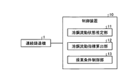
- FIG. 2 is a block diagram showing the configuration of the control device of the continuous casting machine which is an embodiment of the present invention.
- FIG. 3 is a schematic diagram showing a configuration example of the immersion nozzle.
- FIG. 4 is a diagram showing an example of changes in the low flow velocity area due to changes in the magnetic flux density of the electromagnetic stirring magnetic field.
- FIG. 5 is a figure which shows an example of the change of the molten steel surface maximum flow velocity with the change of the magnetic flux density of an electromagnetic stirring magnetic field.
- FIG. 6 is a diagram showing an example of changes in the molten steel surface maximum flow velocity with changes in the magnetic flux density of the electromagnetic stirring magnetic field and the nozzle immersion depth.
- FIG. 7 is a diagram showing an example of a change in the defect mixing rate of the slab depending on whether or not the operating conditions are controlled.
- FIG. 1 is a schematic diagram showing a configuration example of a continuous casting machine to which the present invention is applied.
- a mold 4 is provided vertically below a tundish 3 filled with molten steel 2, and a supply port for the molten steel 2 to the mold 4 is provided at the bottom of the tundish 3.
- the dipping nozzle 5 is provided.
- Molten steel 2 is continuously poured from a tundish 3 into a mold 4, cooled by a mold 4 in which a water-cooled pipe is embedded, and drawn from the lower part of the mold 4 to form a slab.
- the opening degree of the immersion nozzle 5 is adjusted by a sliding gate nozzle or the like (not shown) provided immediately above the immersion nozzle 5 according to the drawing speed.
- the mold 4 is provided with a plurality of temperature sensors on the F surface and the B surface, which are both ends in the thickness direction of the cast slab. Each temperature sensor measures the temperature of the molten steel 2 at each installation position. Further, the mold 4 is provided with a coil (not shown) that generates an electromagnetic stirring magnetic field for rotating the molten metal surface.
- FIG. 2 is a block diagram showing the configuration of the control device of the continuous casting machine which is an embodiment of the present invention.
- a control device 10 of a continuous casting machine is configured by an information processing device such as a computer, and an internal arithmetic processing device such as a CPU (Central Processing Unit) is a computer program.
- an information processing device such as a computer
- an internal arithmetic processing device such as a CPU (Central Processing Unit) is a computer program.
- CPU Central Processing Unit
- the molten steel flow state estimation unit 11 uses a known technique such as the molten steel flow state estimation method described in Patent Document 2 to estimate the flow state of the molten steel 2 in the mold 4 online.
- the molten steel flow state estimation unit 11 uses the physical model such as computational fluid dynamics in consideration of the turbulent flow model and the operating conditions of the continuous casting machine 1 and the measured value of the temperature sensor installed in the mold 4. From this, the flow state of the molten steel 2 in the mold 4 is estimated online.
- Examples of operating conditions of the continuous casting machine 1 include casting width, casting speed, magnetic flux density of electromagnetic stirring magnetic field, immersion depth of the immersion nozzle 5 (nozzle immersion depth), and the like.
- the molten steel flow index calculation unit 12 uses the data on the flow state of the molten steel 2 estimated by the molten steel flow state estimation unit 11 to determine the molten steel flow index that causes impurities to mix into the slab (slab) in the mold 4. Estimate online. Here, as the impurities mixed into the slab, there are inclusions originating from the mold powder.
- the mold powder is a lubricant that is constantly supplied to the upper surface of the molten steel poured into the mold 4 to prevent seizure between the mold 4 and the slab, and also has a heat retaining effect for the molten steel 2.
- the mold powder is in contact with the molten steel 2 in a molten state, and the molten steel 2 is flowing at a certain flow velocity.
- the flow velocity of the molten steel 2 at the contact position with the mold powder is referred to as the surface velocity of the molten steel 2. Therefore, if the surface flow velocity of the molten steel 2 becomes excessively high, the molten powder may be caught in the molten steel 2 to cause inclusion defects.
- the solidification interface flow velocity means the flow velocity of the molten steel in the region near the solidification shell in the mold.
- the molten steel flow index calculation unit 12 calculates the molten steel flow state calculation mesh (width direction and thickness) of the uppermost step (meniscus: height position of molten steel surface) of the mold 4 from the data of the flowing state of the molten steel 2.
- the maximum value of the molten steel flow velocity in all directions is calculated as the molten steel surface maximum flow velocity. Further, the molten steel flow index calculation unit 12 uses the data of the flowing state of the molten steel 2 in the molten steel flowing state calculation mesh (the entire area in the width direction) at predetermined positions in the height direction (casting direction) and the thickness direction of the mold 4. The area of the molten steel flow state calculation mesh in which the molten steel flow velocity is equal to or lower than a predetermined value is calculated.
- the molten steel flow index calculation unit 12 determines the area of the molten steel flow state calculation mesh in which the molten steel flow velocity is equal to or lower than a predetermined value in the entire region in the width direction and in the mold height direction at least 200 mm below the meniscus position. The long sides of the mold are summed up on each side, and the value is taken as the low flow velocity area. Further, the molten steel flow index calculation unit 12 determines the maximum value of the turbulent flow energy in the molten steel flow state calculation mesh (entire region in the width direction and the thickness direction) of the uppermost stage of the mold 4 from the data of the flowing state of the molten steel 2. Calculated as the maximum value of surface turbulence energy.
- the turbulent flow energy is a value that indicates the strength of the turbulence of the flow, and is given based on the magnitude of the deviation from the time average value of the time-varying flow velocity at a certain spatial position.
- the turbulent flow energy is given by the following mathematical formula.
- U is the instantaneous value of the fluid velocity at a certain spatial position
- U ave is the time average value of the fluid velocity at a certain spatial position
- U i is the time average value of the fluid velocity at a certain spatial position. Indicates a shift.
- the low flow velocity area is an effective index because it has an effect of reducing impurities (air bubbles and inclusions) captured by the molten steel 2 in the solidified shell when the molten steel flow at the solidification interface of the slab is fast.
- the flow velocity to be determined as a low flow velocity may be individually determined according to the steel type component, the required quality level, the mold size, etc., and is not fixed. According to the investigation by the present inventors, a value less than 0.05 m/s can be adopted as a criterion for determining a low flow velocity.
- the low flow velocity area is, for example, when the unit area of the molten steel flow state calculation mesh is 1 cm 2 (0.0001 m 2 ), and the unit mesh determined to have a low flow velocity on one side of the long side of the mold is 100 mesh, It is assumed that the low flow velocity area is 0.01 m 2 .
- the appropriate value of the low flow velocity area may be individually determined according to the steel type component, the required quality level, the mold size, etc., and should not be set to a constant value. According to a study by the present inventors, when the required quality level is strict, 0.01 m 2 or less is used, and when the required quality level is not so strict, 0.02 m 2 or less is used as a guideline. Can be adopted.
- the molten steel surface maximum flow velocity is an effective index because it has the effect of reducing the entrainment of mold powder into the molten steel 2 when the molten steel flow on the molten steel surface is slow. Further, the maximum value of the molten steel surface turbulent flow energy is an effective index for the same reason as the molten steel surface maximum flow velocity.
- the operating condition control unit 13 determines the casting speed, the magnetic flux density of the electromagnetic stirring magnetic field, and the nozzle immersion depth according to the molten steel flow index. Control operating conditions such as For example, when the area where the coagulation interface flow velocity is equal to or lower than a predetermined value exceeds a predetermined value, the operating conditions are controlled so that the magnetic flux density of the electromagnetic stirring magnetic field is increased and the electromagnetic stirring force is strengthened. This is because if the flow velocity is further applied to the molten steel in the mold by the electromagnetic stirring force, the molten steel flow velocity will increase even at the position where the solidification interface flow velocity is below a predetermined value.
- the operating condition may be controlled so that the depth of the immersion nozzle is shallow. This is because when the depth of the immersion nozzle is made shallower, the influence of the discharge flow of the molten steel discharged from the immersion nozzle appears more on the molten steel surface side and acts to increase the molten steel flow velocity on the molten steel surface.
- the operating conditions may be controlled so as to increase the depth of the immersion nozzle while increasing the magnetic flux density of the electromagnetic stirring magnetic field.
- the depth of the immersion nozzle is increased, the influence of the molten steel discharge flow discharged from the immersion nozzle is less likely to appear on the molten steel surface side, and acts to reduce the molten steel surface flow velocity and/or the molten steel surface turbulent energy. is there.
- the flow state of the molten steel 2 in the mold 4 changes according to the operating state of the continuous casting machine 1.
- the immersion nozzle 5 having the discharge ports 5a at two positions on the left and right inclusion of alumina or the like adheres to the discharge ports 5a on one side, so that the molten steel in the mold 4 is melted.
- This drift occurs even under the same operating conditions such as the casting width, casting speed, and magnetic flux density of the electromagnetic stirring magnetic field. Therefore, the flow state of molten steel including drift is measured using the measurement value of the temperature sensor installed in the mold 4.
- the molten steel flow index can be accurately estimated online by accurately reproducing.
- the molten steel flow index calculation unit 12 by correcting the calculation conditions in the molten steel flow index calculation unit 12 so as to correspond to the measured values of the temperature sensor installed in the mold 4 and sequentially updating the calculated values, the molten steel flow index can be obtained more accurately online.
- the number of temperature sensors installed, the pitch, and the sampling interval of the measurement values may be set within a range that is possible depending on the environment in which the present invention is implemented. According to the investigation by the present inventors, when the temperature sensors are arranged at a pitch of 50 mm or less and a pitch of 100 mm or less in the casting direction and the width direction, respectively, and measurement values are collected at intervals of 1 second or less, the molten steel flow index calculation The calculation accuracy of the unit 12 is further improved.
- the low flow velocity area was considered as the area where the solidification interface flow velocity is below a predetermined value, but the molten steel flow index is not limited to the flow velocity of the solidification interface itself. If there is a region with a low flow velocity in the molten steel flow (stirring flow) caused by the electromagnetic stirring magnetic field, etc., such a region will adversely affect the capture of bubbles and inclusions at the solidification interface. It can be used as an indicator. As described above, the low flow velocity area is not limited to the solidification interface flow velocity, and various ways of definition are possible.
- the maximum value of the molten steel surface flow velocity and the maximum value of the molten steel surface turbulent flow energy represent the surface state of the molten steel and are associated with the entrainment of mold powder as described above. Therefore, the molten steel flow index is not limited to these maximum values, and can be used as the molten steel flow index by appropriately defining the velocity or flow state of the molten steel surface.
- the present invention was applied in continuous casting of ultra low carbon steel.
- the mold size is 1200 mm in width and 260 mm in thickness, and the casting speed in the steady state is 1.6 m/min.
- the proper range of the low flow velocity area was set to 0.02 m 2 or less, and the proper range of the molten steel surface maximum flow velocity was set to 0.05 to 0.30 m/s for the operation.
- the low flow velocity area calculated during the operation of the continuous casting machine 1 became larger than the appropriate range, so the magnetic flux density of the electromagnetic stirring magnetic field was increased by 5%.
- the molten steel stirring force in the mold 4 became stronger, the solidification interface flow velocity increased, and the low flow velocity area decreased.
- the molten steel surface maximum flow velocity may exceed the appropriate range as shown in FIG. Therefore, the nozzle immersion depth was increased by 30 mm. This is because the discharge flow of the immersion nozzle 5 collides with the copper plate of the casting mold and is reversed, and the flow overlaps the stirring flow to increase the molten steel surface flow velocity. Is smaller, and the molten steel surface flow velocity can be suppressed.
- the operating conditions as shown in FIG. 6, it was possible to control the maximum flow velocity of the molten steel surface within an appropriate range while reducing the low flow velocity area.
- a control method for a continuous casting machine a control device for a continuous casting machine, and a production method for a slab, which are capable of producing a high quality slab.
Landscapes
- Engineering & Computer Science (AREA)
- Mechanical Engineering (AREA)
- Continuous Casting (AREA)
Abstract
本発明の一実施形態である連続鋳造機の制御装置10は、連続鋳造機1の操業条件及び鋳型内の溶鋼の温度データを用いて、鋳型内における溶鋼の流動状態をオンラインで推定する溶鋼流動状態推定部11と、溶鋼流動状態推定部11によって推定された溶鋼の流動状態に基づいて、鋳型内で鋳片へ不純物が混入する要因となる溶鋼流動指標をオンラインで算出する溶鋼流動指標算出部12と、溶鋼流動指標算出部12によって算出された溶鋼流動指標が適正範囲内になるように、連続鋳造機1の操業条件を制御する操業条件制御部13と、を備えている。
Description
本発明は、連続鋳造機の制御方法、連続鋳造機の制御装置、及び鋳片の製造方法に関する。
近年、連続鋳造機において製造されるスラブ等の鋳片に対する高品質化の要求がますます高まっている。このため、連続鋳造機の鋳型内における溶鋼の状況を制御する技術が開発されている。例えば特許文献1には、鋳型内の溶鋼に磁場を印加する方法が記載されている。鋳型内の溶鋼に磁場を印加して溶鋼流動を制御することにより、鋳片の品質を安定化させることができる。しかしながら、溶鋼に磁場を印加しても予期せぬ操業変動に起因して完全には溶鋼流動を制御することは困難である。このため、鋳型銅板に埋め込まれた測温素子による溶鋼の測温結果を併用して操業を制御する技術が提案されている。例えば特許文献2には、鋳型内銅板温度データに基づいて鋳型内の溶鋼流動を補正することにより、溶鋼流動を高精度に推定する方法が記載されている。
なお、鋳片に要求される品質の一つとして、鋳片の表層近傍に混入した気泡や介在物等の不純物による欠陥が少ないことが挙げられる。連続鋳造機では、浸漬ノズルを介して鋳型内に注湯された溶鋼は、鋳型壁面から殻状に凝固を開始し(以下、殻状に凝固した鋼を凝固シェルと称する)、鋳造の進行と共に凝固シェル厚みを増加させていく。鋳型内に注湯される溶鋼中には気泡や介在物が懸濁しているが、これら気泡や介在物が凝固シェルに捕捉されてそのまま凝固が進行すると上記の欠陥となる。
溶鋼中に懸濁した気泡や介在物は、凝固界面の溶鋼流速が速いほど凝固シェルに捕捉されにくいことが知られており、この観点から鋳型内の溶鋼流動を適切に制御する技術開発も行なわれている。例えば特許文献3には、鋳造速度が1.6m/min程度と比較的遅い場合等において、凝固界面での溶鋼流速が不足して欠陥が発生することを抑制するための技術が開示されている。具体的には、この技術は、浸漬ノズルから吐出される溶鋼の吐出流に制動力が作用するように移動磁場を印加して連続鋳造する際、移動磁場印加位置に対する浸漬ノズルの吐出口の位置及び吐出角度を適正な範囲とするものである。
特許文献2には、鋳型内の溶鋼流動を高精度に推定する方法が記載されているが、鋳型内で鋳片へ不純物が混入する要因となる溶鋼流動指標を推定し、溶鋼流動指標を適正範囲内に制御することは開示、示唆されていない。高品質な鋳片を製造するためには、鋳型内で鋳片へ不純物が混入する要因となる溶鋼流動指標を推定し、溶鋼流動指標を適正範囲内に制御することが必要である。このため、特許文献2に記載の方法だけでは、高品質な鋳片を製造することは困難である。
一方、特許文献3には、凝固界面での溶鋼流速を適正範囲に制御する方法が記載されているが、この適正範囲はあくまで設備の幾何学的関係のみで規定されたものである。しかしながら、実際の連続鋳造では、浸漬ノズルのノズル孔に介在物が付着して偏流が生じる等の溶鋼流速の変動要因があり、こうした変動が生じた場合にも、その変動状況に応じて凝固界面での溶鋼流速を適正範囲内に制御する必要がある。すなわち、鋳型内で気泡や介在物等の不純物が鋳片へ混入する要因となる凝固界面の溶鋼流速の低下を、連続鋳造機の操業条件及び鋳型内の溶鋼の温度データを用いて溶鋼流動指標として推定し、その推定結果に基づき溶鋼流動指標を適正範囲内に制御することによって、より高品質な鋳片を製造することが可能になる。
本発明は、上記課題に鑑みてなされたものであって、その目的は、高品質な鋳片を製造可能な連続鋳造機の制御方法、連続鋳造機の制御装置、及び鋳片の製造方法を提供することにある。
本発明に係る連続鋳造機の制御方法は、連続鋳造機の操業条件及び鋳型内の溶鋼の温度データを用いて、鋳型内における溶鋼の流動状態をオンラインで推定する溶鋼流動状態推定ステップと、前記溶鋼流動状態推定ステップにおいて推定された溶鋼の流動状態に基づいて、鋳型内で鋳片へ不純物が混入する要因となる溶鋼流動指標をオンラインで算出する溶鋼流動指標算出ステップと、前記溶鋼流動指標算出ステップにおいて算出された溶鋼流動指標が適正範囲内になるように、前記連続鋳造機の操業条件を制御する操業条件制御ステップと、を含む。
前記溶鋼流動指標には、電磁攪拌磁場により生じる攪拌流の中で流速が所定値以下となっている領域の面積が含まれているとよい。
前記溶鋼流動指標には、溶鋼表面の速度又は流動状態が含まれているとよい。
前記溶鋼流動指標には、凝固界面流速が所定値以下となる面積が含まれているとよい。
前記溶鋼流動指標には、溶鋼表面流速の最大値が含まれているとよい。
前記溶鋼流動指標には、溶鋼表面乱流エネルギーの最大値が含まれているとよい。
前記鋳型内の溶鋼の温度データは、鋳型に設置された温度センサの測定値を含む温度データであるとよい。
前記連続鋳造機の操業条件には、鋳造速度、電磁撹拌磁場の磁束密度、及びノズル浸漬深さのうちの少なくとも一つが含まれているとよい。
本発明に係る連続鋳造機の制御装置は、連続鋳造機の操業条件及び鋳型内の溶鋼の温度データを用いて、鋳型内における溶鋼の流動状態をオンラインで推定する溶鋼流動状態推定部と、前記溶鋼流動状態推定部によって推定された溶鋼の流動状態に基づいて、鋳型内で鋳片へ不純物が混入する要因となる溶鋼流動指標をオンラインで算出する溶鋼流動指標算出部と、前記溶鋼流動指標算出部によって算出された溶鋼流動指標が適正範囲内になるように、前記連続鋳造機の操業条件を制御する操業条件制御部と、を備える。
本発明に係る鋳片の製造方法は、本発明に係る連続鋳造機の制御方法を用いて連続鋳造機を制御しながら鋳片を製造するステップを含む。
本発明に係る連続鋳造機の制御方法、連続鋳造機の制御装置、及び鋳片の製造方法によれば、高品質な鋳片を製造することができる。
以下、図面を参照して、本発明の一実施形態である連続鋳造機の制御装置の構成及びその動作について説明する。
〔連続鋳造機の構成〕
まず、図1を参照して、本発明が適用される連続鋳造機の一構成例について説明する。
まず、図1を参照して、本発明が適用される連続鋳造機の一構成例について説明する。
図1は、本発明が適用される連続鋳造機の一構成例を示す模式図である。図1に示すように、この連続鋳造機1では、溶鋼2が満たされたタンディッシュ3の鉛直方向下方に鋳型4が設けられ、タンディッシュ3の底部に鋳型4への溶鋼2の供給口となる浸漬ノズル5が設けられている。溶鋼2は、タンディッシュ3から連続的に鋳型4に注がれ、水冷管が埋設された鋳型4により冷却され、鋳型4の下部から引き抜かれてスラブとなる。その際、マスバランスを保証するため、引き抜き速度に応じて浸漬ノズル5の直上に設けられた図示しないスライディングゲートノズル等により浸漬ノズル5の開度が調整される。鋳型4には、鋳造されるスラブの厚み方向の両端となるF面及びB面に、複数の温度センサが設置されている。各温度センサは、各設置位置での溶鋼2の温度を測定する。また、鋳型4には、湯面を回転させる電磁撹拌磁場を発生させる図示しないコイルが設置されている。
〔制御装置の構成〕
次に、図2を参照して、本発明の一実施形態である連続鋳造機の制御装置の構成について説明する。
次に、図2を参照して、本発明の一実施形態である連続鋳造機の制御装置の構成について説明する。
図2は、本発明の一実施形態である連続鋳造機の制御装置の構成を示すブロック図である。図2に示すように、本発明の一実施形態である連続鋳造機の制御装置10は、コンピュータ等の情報処理装置によって構成され、CPU(Central Processing Unit)等の内部の演算処理装置がコンピュータプログラムを実行することにより、溶鋼流動状態推定部11、溶鋼流動指標算出部12、及び操業条件制御部13として機能する。
溶鋼流動状態推定部11は、特許文献2に記載の溶鋼の流動状態推定方法等の周知の技術を利用して、鋳型4内における溶鋼2の流動状態をオンラインで推定する。具体的には、溶鋼流動状態推定部11は、乱流モデルを考慮した数値流体力学等の物理モデルを用いて、連続鋳造機1の操業条件及び鋳型4に設置されている温度センサの測定値から鋳型4内における溶鋼2の流動状態をオンラインで推定する。連続鋳造機1の操業条件としては、鋳造幅、鋳造速度、電磁撹拌磁場の磁束密度、浸漬ノズル5の浸漬深さ(ノズル浸漬深さ)等を例示できる。
溶鋼流動指標算出部12は、溶鋼流動状態推定部11によって推定された溶鋼2の流動状態のデータを用いて、鋳型4内でスラブ(鋳片)へ不純物が混入する要因となる溶鋼流動指標をオンラインで推定する。ここで、スラブへ混入する不純物としては、モールドパウダーを起源とした介在物がある。モールドパウダーは、鋳型4内に注入された溶鋼の上表面に常時供給され、鋳型4とスラブとの焼き付きを防止する潤滑剤であり、溶鋼2の保温効果等も有している。鋳型4内の溶鋼2の最上部では、モールドパウダーは溶融状態で溶鋼2と接触し、溶鋼2はある流速で流動している。ここで、本発明では、モールドパウダーとの接触位置における溶鋼2の流速を溶鋼2の表面流速と称する。そのため、溶鋼2の表面流速が過大となると、溶融パウダが溶鋼2の内部に巻き込まれて介在物欠陥となる可能性がある。また、アルミナ等の介在物は浸漬ノズル5から供給されるArガス等の気泡と共に溶鋼流動にあわせて上昇し、溶融パウダ層に吸収されて溶鋼2の清浄化が行われるが、凝固界面流速が遅い場合には、介在物や気泡が凝固シェル側にトラップされ、製品時に表面欠陥の原因となる可能性がある。ここで、凝固界面流速とは、鋳型内の凝固シェルの近傍領域における溶鋼の流速のことを意味する。
このため、鋳型4内でスラブへ不純物が混入する要因となる溶鋼流動指標としては、鋳型4内の溶鋼表面流速の最大値(溶鋼表面最大流速)、凝固界面流速が所定値以下となる面積(低流速面積)、溶鋼表面乱流エネルギーの最大値を例示することができる。具体的には、溶鋼流動指標算出部12は、溶鋼2の流動状態のデータから、鋳型4の最上段部(メニスカス:溶鋼湯面の高さ位置)の溶鋼流動状態計算メッシュ(幅方向及び厚み方向の全領域)における溶鋼流速の最大値を溶鋼表面最大流速として算出する。また、溶鋼流動指標算出部12は、溶鋼2の流動状態のデータから、鋳型4の高さ方向(鋳造方向)及び厚み方向の所定位置にある溶鋼流動状態計算メッシュ(幅方向は全領域)において溶鋼流速が所定値以下である溶鋼流動状態計算メッシュの面積を算出する。例えば溶鋼流動指標算出部12は、幅方向の全領域、且つ、鋳型高さ方向には少なくともメニスカス位置から200mm下方までの範囲で、溶鋼流速が所定値以下である溶鋼流動状態計算メッシュの面積を鋳型長辺の片面毎に合計して、その値をそれぞれ低流速面積とする。また、溶鋼流動指標算出部12は、溶鋼2の流動状態のデータから、鋳型4の最上段部の溶鋼流動状態計算メッシュ(幅方向、厚み方向の全領域)における乱流エネルギーの最大値を溶鋼表面乱流エネルギーの最大値として算出する。
ここで、乱流エネルギーとは、流れの乱れの強さを示す値であり、ある空間位置において時間的に変動する流速の時間平均値からのずれの大きさに基づき与えられる。具体的には、乱流エネルギーは以下に示す数式で与えられる。
k=(1/2)・Ui
2
U=Uave+Ui
kは乱流エネルギー、Uはある空間位置における流体の流速の瞬時値、Uaveはある空間位置における流体の流速の時間平均値、Uiはある空間位置における流体の流速の時間平均値からのずれを示す。
U=Uave+Ui
kは乱流エネルギー、Uはある空間位置における流体の流速の瞬時値、Uaveはある空間位置における流体の流速の時間平均値、Uiはある空間位置における流体の流速の時間平均値からのずれを示す。
低流速面積は、スラブの凝固界面における溶鋼流動が速い場合には溶鋼2により凝固シェルに補足される不純物(気泡や介在物)を低減できる効果があることから有効な指標となる。ここで低流速であると判定すべき流速は、鋼種成分や要求される品質レベル及び鋳型寸法等に応じて個別に定めればよく、一定値に定めるべきものではない。なお、本発明者らの調査によれば、低流速と判定する目安として、0.05m/s未満を採用することができる。また、低流速面積は、例えば、溶鋼流動状態計算メッシュの単位面積を1cm2(0.0001m2)とした場合、鋳型長辺の片面について低流速と判定された単位メッシュが100メッシュあるとき、低流速面積が0.01m2あるとする。また、低流速面積の適正値についても、鋼種成分や要求される品質レベル及び鋳型寸法等に応じて個別に定めればよく、一定値に定めるべきものではない。なお、本発明者らの調査によれば、要求される品質レベルが厳しい場合は、0.01m2以下、要求される品質レベルがさほど厳しくない場合は、0.02m2以下、をそれぞれ目安として採用することができる。溶鋼表面最大流速は、溶鋼表面における溶鋼流動が遅い場合にはモールドパウダーの溶鋼2内への巻き込みを低減できる効果があることから有効な指標となる。また、溶鋼表面乱流エネルギーの最大値は、溶鋼表面最大流速と同様な理由から有効な指標となる。
操業条件制御部13は、溶鋼流動指標算出部12によって算出された溶鋼流動指標を適正範囲内に制御するために、溶鋼流動指標に応じて鋳造速度、電磁撹拌磁場の磁束密度、及びノズル浸漬深さ等の操業条件を制御する。例えば、凝固界面流速が所定値以下となる面積が予め定めた値を超えた場合は、電磁撹拌磁場の磁束密度を大きくして電磁撹拌力を強めるよう操業条件を制御する。電磁撹拌力によって鋳型内の溶鋼にさらに流速を付与すれば、凝固界面流速が所定値以下となった位置においても、溶鋼流速が増加するよう作用するからである。また、電磁撹拌磁場の磁束密度を大きくしても、依然、凝固界面流速が所定値以下となる面積が予め定めた値を超えており、しかも凝固界面流速が所定値以下となる位置が溶鋼表面に近い場合は、浸漬ノズルの深さを浅くするよう操業条件を制御してもよい。浸漬ノズルの深さを浅くすると、浸漬ノズルから吐出される溶鋼の吐出流の影響が、より溶鋼表面側に現れ、溶鋼表面の溶鋼流速を増加させるよう作用するからである。一方、電磁撹拌磁場の磁束密度を大きくすることで、凝固界面流速が所定値以下となる面積が予め定めた値未満となったものの、溶鋼表面流速及び/又は溶鋼表面乱流エネルギーが所定値を超える場合は、電磁撹拌磁場の磁束密度を大きくしたまま、浸漬ノズルの深さを深くするよう操業条件を制御してもよい。浸漬ノズルの深さを深くすると、浸漬ノズルから吐出される溶鋼の吐出流の影響が、溶鋼表面側に現れにくくなり、溶鋼表面流速及び/又は溶鋼表面乱流エネルギーを減少させるよう作用するからである。
一般に、鋳型4内における溶鋼2の流動状態は連続鋳造機1の操業状態の違いに応じて変化する。例えば図3に示すように、左右の2箇所に吐出口5aがある浸漬ノズル5を使用している場合、片側の吐出口5aにアルミナ等の介在物が付着することにより、鋳型4内における溶鋼2の吐出流に左右差(偏流)が生じる場合がある。この偏流は、鋳造幅、鋳造速度、電磁撹拌磁場の磁束密度といった操業条件が同じあっても発生するため、鋳型4に設置されている温度センサの測定値を用いて偏流を含む溶鋼の流動状態を精度よく再現することにより精度よく溶鋼流動指標をオンラインで推定する。
すなわち、鋳型4に設置されている温度センサの測定値に対応するよう、溶鋼流動指標算出部12における計算条件を修正し、計算値を逐次更新することで、オンラインでより精度よく溶鋼流動指標を推定する。なお、温度センサの設置数やピッチ及び測定値のサンプリング間隔は、本発明を実施する環境等に応じて可能な範囲で定めればよい。本発明者らの調査によれば、温度センサを、鋳造方向及び幅方向にそれぞれ50mmピッチ以下及び100mmピッチ以下で配置し、測定値を1秒間隔以下で採取するようにすると、溶鋼流動指標算出部12の計算精度がより向上する。溶鋼流動指標をオンラインで推定することにより、欠陥発生リスクが少ない適正範囲内で操業ができているかを把握でき、操業条件を変更することによって溶鋼流動指標を適正範囲内に制御することができる。結果、高品質なスラブを製造することができる。
なお、本実施形態では、低流速面積を凝固界面流速が所定値以下となる面積であるとして検討したが、溶鋼流動指標としては、凝固界面そのものの流速には限られない。電磁攪拌磁場等により生じる溶鋼流動(攪拌流)の中で低流速となっている領域があれば、このような領域は凝固界面への気泡や介在物補足に悪影響を及ぼすから、これを溶鋼流動指標とすることができる。このように低流速面積は凝固界面流速に限られずに種々の定義の仕方が可能である。同様に、溶鋼表面流速の最大値及び溶鋼表面乱流エネルギーの最大値は、溶鋼の表面状態を表しており、上記したようにモールドパウダーの巻き込みに関連する。従って、溶鋼流動指標としては、これら最大値に限られず、溶鋼表面の速度又は流動状態を適宜規定することで溶鋼流動指標とすることができる。
本実施例として、極低炭素鋼の連続鋳造において、本発明を適用した。鋳型寸法は、幅1200mm、厚み260mmで、定常状態の鋳造速度は1.6m/minである。本実施例では、低流速面積の適正範囲を0.02m2以下、溶鋼表面最大流速の適正範囲を0.05~0.30m/sと設定して操業を行なった。操業中、連続鋳造機1の操業中に算出された低流速面積が適正範囲より大きくなったために、電磁撹拌磁場の磁束密度を5%大きくした。その結果、図4に示すように、鋳型4内の溶鋼撹拌力が強くなり、凝固界面流速がアップし、低流速面積が減少した。しかしながら、この操業条件の変更によって溶鋼撹拌力が強くなったことにより、図5に示すように、溶鋼表面最大流速が適正範囲を超えてしまう場合があった。そこで、ノズル浸漬深さを30mm深くした。これは、浸漬ノズル5の吐出流が鋳型銅板に衝突、反転して流れが撹拌流と重なりあって溶鋼表面流速を高めているので、浸漬ノズル5の浸漬深さを深くすることにより、反転流が小さくなり、溶鋼表面流速を抑制できるためである。この操業条件変更により、図6に示すように、低流速面積を小さくしつつ、溶鋼表面最大流速を適正範囲内に制御できた。また、オンラインで溶鋼流動指標(溶鋼表面最大流速、低流速面積、及び溶鋼表面乱流エネルギーの最大値)を推定することにより、溶鋼流動指標を適正範囲にするための操業条件を制御することが可能となり、結果として、図7に示すように、スラブ品質指標であるスラブの欠陥混入率を低減することができた。このようにして、本発明に係る連続鋳造機の制御方法によれば、優れた品質のスラブを製造できることが確認された。
以上、本発明者らによってなされた発明を適用した実施の形態について説明したが、本実施形態による本発明の開示の一部をなす記述及び図面により本発明は限定されることはない。すなわち、本実施形態に基づいて当業者等によりなされる他の実施の形態、実施例、及び運用技術等は全て本発明の範疇に含まれる。
本発明によれば、高品質な鋳片を製造可能な連続鋳造機の制御方法、連続鋳造機の制御装置、及び鋳片の製造方法を提供することができる。
1 連続鋳造機
2 溶鋼
3 タンディッシュ
4 鋳型
5 浸漬ノズル
10 制御装置
11 溶鋼流動状態推定部
12 溶鋼流動指標算出部
13 操業条件制御部
2 溶鋼
3 タンディッシュ
4 鋳型
5 浸漬ノズル
10 制御装置
11 溶鋼流動状態推定部
12 溶鋼流動指標算出部
13 操業条件制御部
Claims (10)
- 連続鋳造機の操業条件及び鋳型内の溶鋼の温度データを用いて、鋳型内における溶鋼の流動状態をオンラインで推定する溶鋼流動状態推定ステップと、
前記溶鋼流動状態推定ステップにおいて推定された溶鋼の流動状態に基づいて、鋳型内で鋳片へ不純物が混入する要因となる溶鋼流動指標をオンラインで算出する溶鋼流動指標算出ステップと、
前記溶鋼流動指標算出ステップにおいて算出された溶鋼流動指標が適正範囲内になるように、前記連続鋳造機の操業条件を制御する操業条件制御ステップと、
を含む、連続鋳造機の制御方法。 - 前記溶鋼流動指標には、電磁攪拌磁場により生じる攪拌流の中で流速が所定値以下となっている領域の面積が含まれる、請求項1に記載の連続鋳造機の制御方法。
- 前記溶鋼流動指標には、溶鋼表面の速度又は流動状態が含まれる、請求項1又は2に記載の連続鋳造機の制御方法。
- 前記溶鋼流動指標には、凝固界面流速が所定値以下となる面積が含まれる、請求項1~3のうち、いずれか1項に記載の連続鋳造機の制御方法。
- 前記溶鋼流動指標には、溶鋼表面流速の最大値が含まれる、請求項4に記載の連続鋳造機の制御方法。
- 前記溶鋼流動指標には、溶鋼表面乱流エネルギーの最大値が含まれる、請求項4又は5に記載の連続鋳造機の制御方法。
- 前記鋳型内の溶鋼の温度データは、鋳型に設置された温度センサの測定値を含む温度データである、請求項1~6のいずれか1項に記載の連続鋳造機の制御方法。
- 前記連続鋳造機の操業条件には、鋳造速度、電磁撹拌磁場の磁束密度、及びノズル浸漬深さのうちの少なくとも一つが含まれる、請求項1~7のうち、いずれか1項に記載の連続鋳造機の制御方法。
- 連続鋳造機の操業条件及び鋳型内の溶鋼の温度データを用いて、鋳型内における溶鋼の流動状態をオンラインで推定する溶鋼流動状態推定部と、
前記溶鋼流動状態推定部によって推定された溶鋼の流動状態に基づいて、鋳型内で鋳片へ不純物が混入する要因となる溶鋼流動指標をオンラインで算出する溶鋼流動指標算出部と、
前記溶鋼流動指標算出部によって算出された溶鋼流動指標が適正範囲内になるように、前記連続鋳造機の操業条件を制御する操業条件制御部と、
を備える、連続鋳造機の制御装置。 - 請求項1~8のうち、いずれか1項に記載の連続鋳造機の制御方法を用いて連続鋳造機を制御しながら鋳片を製造するステップを含む、鋳片の製造方法。
Priority Applications (8)
| Application Number | Priority Date | Filing Date | Title |
|---|---|---|---|
| KR1020217026128A KR102695836B1 (ko) | 2019-02-19 | 2020-02-06 | 연속 주조기의 제어 방법, 연속 주조기의 제어 장치 및, 주편의 제조 방법 |
| CN202080013723.9A CN113423521B (zh) | 2019-02-19 | 2020-02-06 | 连续铸造机的控制方法、连续铸造机的控制装置及铸片的制造方法 |
| EP20759007.6A EP3928890B1 (en) | 2019-02-19 | 2020-02-06 | Control method for continuous casting machine, control device for continuous casting machine, and manufacturing method for casting |
| BR112021015867-7A BR112021015867B1 (pt) | 2019-02-19 | 2020-02-06 | Método e dispositivo de controle para máquina de lingotamento contínuo e método de fabricação para peça fundida |
| PCT/JP2020/004546 WO2020170836A1 (ja) | 2019-02-19 | 2020-02-06 | 連続鋳造機の制御方法、連続鋳造機の制御装置、及び鋳片の製造方法 |
| JP2020532835A JP6981551B2 (ja) | 2019-02-19 | 2020-02-06 | 連続鋳造機の制御方法、連続鋳造機の制御装置、及び鋳片の製造方法 |
| US17/422,674 US11890671B2 (en) | 2019-02-19 | 2020-02-06 | Control method for continuous casting machine, control device for continuous casting machine, and manufacturing method for casting |
| TW109105112A TWI743686B (zh) | 2019-02-19 | 2020-02-18 | 連續鑄造機之控制方法、連續鑄造機之控制裝置、以及鑄片之製造方法 |
Applications Claiming Priority (2)
| Application Number | Priority Date | Filing Date | Title |
|---|---|---|---|
| JP2019-027374 | 2019-02-19 | ||
| JP2019027374 | 2019-02-19 |
Publications (1)
| Publication Number | Publication Date |
|---|---|
| WO2020170563A1 true WO2020170563A1 (ja) | 2020-08-27 |
Family
ID=72145058
Family Applications (1)
| Application Number | Title | Priority Date | Filing Date |
|---|---|---|---|
| PCT/JP2019/048374 Ceased WO2020170563A1 (ja) | 2019-02-19 | 2019-12-11 | 連続鋳造機の制御方法、連続鋳造機の制御装置、及び鋳片の製造方法 |
Country Status (3)
| Country | Link |
|---|---|
| KR (1) | KR102695836B1 (ja) |
| CN (1) | CN113423521B (ja) |
| WO (1) | WO2020170563A1 (ja) |
Citations (2)
| Publication number | Priority date | Publication date | Assignee | Title |
|---|---|---|---|---|
| JP2011206845A (ja) * | 2010-03-10 | 2011-10-20 | Jfe Steel Corp | 鋼の連続鋳造方法および鋼板の製造方法 |
| JP2017159363A (ja) * | 2016-03-02 | 2017-09-14 | Jfeスチール株式会社 | 溶鋼の流動状態推定方法、流動状態推定装置、溶鋼の流動状態のオンライン表示装置および鋼の連続鋳造方法 |
Family Cites Families (12)
| Publication number | Priority date | Publication date | Assignee | Title |
|---|---|---|---|---|
| US5884685A (en) * | 1995-03-29 | 1999-03-23 | Nippon Steel Corporation | Quality prediction and quality control of continuous-cast steel |
| JPH10305353A (ja) * | 1997-05-08 | 1998-11-17 | Nkk Corp | 鋼の連続鋳造方法 |
| WO2000051762A1 (fr) * | 1999-03-02 | 2000-09-08 | Nkk Corporation | Procede et dispositif permettant, en coulee continue, de predire et de reguler la configuration d'ecoulement de l'acier en fusion |
| JP3607882B2 (ja) * | 2000-07-19 | 2005-01-05 | 新日本製鐵株式会社 | 連続鋳造鋳型内全域の凝固シェル厚、溶鋼流速、鋳片品質センシング方法及びその装置。 |
| JP4407260B2 (ja) | 2003-11-28 | 2010-02-03 | Jfeスチール株式会社 | 鋼の連続鋳造方法 |
| KR20120107928A (ko) * | 2009-08-31 | 2012-10-04 | 아이워크, 아이엔씨. | 의족 보철 또는 지지대를 이용하는 기립 시퀀스의 구현 |
| JP4569715B1 (ja) * | 2009-11-10 | 2010-10-27 | Jfeスチール株式会社 | 鋼の連続鋳造方法 |
| US20110174457A1 (en) * | 2010-01-18 | 2011-07-21 | Evraz Inc. Na Canada | Process for optimizing steel fabrication |
| JP2014032719A (ja) * | 2012-08-02 | 2014-02-20 | Sony Corp | 記録再生装置、レーザ駆動パルス調整方法、プログラム |
| JP5935837B2 (ja) | 2014-07-07 | 2016-06-15 | Jfeスチール株式会社 | 溶鋼の流動状態推定方法及び流動状態推定装置 |
| DE102014223750A1 (de) * | 2014-11-20 | 2016-05-25 | Carl Zeiss Smt Gmbh | Projektionsbelichtungsanlage mit mindestens einem Manipulator |
| JP6717843B2 (ja) * | 2015-02-12 | 2020-07-08 | コーニンクレッカ フィリップス エヌ ヴェKoninklijke Philips N.V. | 呼吸パラメータの領域的フィッティングによる呼吸パラメータの同時推定 |
-
2019
- 2019-12-11 WO PCT/JP2019/048374 patent/WO2020170563A1/ja not_active Ceased
-
2020
- 2020-02-06 CN CN202080013723.9A patent/CN113423521B/zh active Active
- 2020-02-06 KR KR1020217026128A patent/KR102695836B1/ko active Active
Patent Citations (2)
| Publication number | Priority date | Publication date | Assignee | Title |
|---|---|---|---|---|
| JP2011206845A (ja) * | 2010-03-10 | 2011-10-20 | Jfe Steel Corp | 鋼の連続鋳造方法および鋼板の製造方法 |
| JP2017159363A (ja) * | 2016-03-02 | 2017-09-14 | Jfeスチール株式会社 | 溶鋼の流動状態推定方法、流動状態推定装置、溶鋼の流動状態のオンライン表示装置および鋼の連続鋳造方法 |
Also Published As
| Publication number | Publication date |
|---|---|
| CN113423521A (zh) | 2021-09-21 |
| KR102695836B1 (ko) | 2024-08-14 |
| KR20210116577A (ko) | 2021-09-27 |
| CN113423521B (zh) | 2023-12-01 |
Similar Documents
| Publication | Publication Date | Title |
|---|---|---|
| KR101047826B1 (ko) | 제어 시스템, 컴퓨터 프로그램 제품, 장치 및 방법 | |
| JP2009183977A (ja) | 連続鋳造における鋳片の軽圧下方法 | |
| Thomas | Fluid flow in the mold | |
| JP2001514078A (ja) | 電磁界を利用した連続鋳造において金属の流動を制御する方法と装置 | |
| JP6358178B2 (ja) | 連続鋳造方法および鋳型の冷却水制御装置 | |
| JP6859919B2 (ja) | ブレークアウト予知方法 | |
| JPH06264B2 (ja) | 連続鋳造における湯面レベル制御方法 | |
| WO2020170836A1 (ja) | 連続鋳造機の制御方法、連続鋳造機の制御装置、及び鋳片の製造方法 | |
| KR102695836B1 (ko) | 연속 주조기의 제어 방법, 연속 주조기의 제어 장치 및, 주편의 제조 방법 | |
| KR20120044433A (ko) | 몰드내 용강 유동 편류 저감장치 및 이를 이용한 저감방법 | |
| KR101400044B1 (ko) | 연주 공정에서의 주조속도 제어 방법 | |
| KR100663916B1 (ko) | 연속 주조 방법 | |
| TWI743686B (zh) | 連續鑄造機之控制方法、連續鑄造機之控制裝置、以及鑄片之製造方法 | |
| CN1330439C (zh) | 控制系统,计算机程序产品,装置和方法 | |
| JP4893068B2 (ja) | 連続鋳造鋳片の凝固完了位置制御方法及び装置並びに連続鋳造鋳片の製造方法 | |
| JP4972776B2 (ja) | 鋳型内溶鋼の流動制御方法及び連続鋳造鋳片の表面品質判定方法 | |
| KR102257856B1 (ko) | 연속주조공정의 용강유동 제어장치 및 이를 이용한 용강유동 제어방법 | |
| RU2775264C1 (ru) | Способ управления для машины непрерывного литья, устройство управления для машины непрерывного литья и способ изготовления отливки | |
| JP2962788B2 (ja) | 連続鋳造鋳型内における溶鋼の偏流制御方法 | |
| RU2763994C1 (ru) | Устройство и способ управления непрерывной разливкой | |
| JPH09182943A (ja) | 鋼の連続鋳造方法 | |
| KR20130013738A (ko) | 연주기 몰드의 탕면 변동 측정장치 및 방법 | |
| JPS62252650A (ja) | 溶鋼連続鋳造鋳型内の偏流制御方法 | |
| KR101675670B1 (ko) | 연속주조 공정의 유동 제어 장치 및 방법 | |
| KR20140017144A (ko) | 연속주조시 응고쉘의 수축량 예측 방법 |
Legal Events
| Date | Code | Title | Description |
|---|---|---|---|
| 121 | Ep: the epo has been informed by wipo that ep was designated in this application |
Ref document number: 19915837 Country of ref document: EP Kind code of ref document: A1 |
|
| NENP | Non-entry into the national phase |
Ref country code: DE |
|
| 122 | Ep: pct application non-entry in european phase |
Ref document number: 19915837 Country of ref document: EP Kind code of ref document: A1 |
|
| NENP | Non-entry into the national phase |
Ref country code: JP |