WO2020170558A1 - 光部品およびレーザ装置 - Google Patents
光部品およびレーザ装置 Download PDFInfo
- Publication number
- WO2020170558A1 WO2020170558A1 PCT/JP2019/048032 JP2019048032W WO2020170558A1 WO 2020170558 A1 WO2020170558 A1 WO 2020170558A1 JP 2019048032 W JP2019048032 W JP 2019048032W WO 2020170558 A1 WO2020170558 A1 WO 2020170558A1
- Authority
- WO
- WIPO (PCT)
- Prior art keywords
- optical fiber
- fiber
- amplification optical
- amplification
- optical component
- Prior art date
- Legal status (The legal status is an assumption and is not a legal conclusion. Google has not performed a legal analysis and makes no representation as to the accuracy of the status listed.)
- Ceased
Links
Images



Classifications
-
- G—PHYSICS
- G02—OPTICS
- G02B—OPTICAL ELEMENTS, SYSTEMS OR APPARATUS
- G02B6/00—Light guides; Structural details of arrangements comprising light guides and other optical elements, e.g. couplings
- G02B6/02—Optical fibres with cladding with or without a coating
-
- G—PHYSICS
- G02—OPTICS
- G02B—OPTICAL ELEMENTS, SYSTEMS OR APPARATUS
- G02B6/00—Light guides; Structural details of arrangements comprising light guides and other optical elements, e.g. couplings
- G02B6/24—Coupling light guides
- G02B6/255—Splicing of light guides, e.g. by fusion or bonding
-
- H—ELECTRICITY
- H01—ELECTRIC ELEMENTS
- H01S—DEVICES USING THE PROCESS OF LIGHT AMPLIFICATION BY STIMULATED EMISSION OF RADIATION [LASER] TO AMPLIFY OR GENERATE LIGHT; DEVICES USING STIMULATED EMISSION OF ELECTROMAGNETIC RADIATION IN WAVE RANGES OTHER THAN OPTICAL
- H01S3/00—Lasers, i.e. devices using stimulated emission of electromagnetic radiation in the infrared, visible or ultraviolet wave range
- H01S3/02—Constructional details
- H01S3/04—Arrangements for thermal management
- H01S3/042—Arrangements for thermal management for solid state lasers
-
- H—ELECTRICITY
- H01—ELECTRIC ELEMENTS
- H01S—DEVICES USING THE PROCESS OF LIGHT AMPLIFICATION BY STIMULATED EMISSION OF RADIATION [LASER] TO AMPLIFY OR GENERATE LIGHT; DEVICES USING STIMULATED EMISSION OF ELECTROMAGNETIC RADIATION IN WAVE RANGES OTHER THAN OPTICAL
- H01S3/00—Lasers, i.e. devices using stimulated emission of electromagnetic radiation in the infrared, visible or ultraviolet wave range
- H01S3/05—Construction or shape of optical resonators; Accommodation of active medium therein; Shape of active medium
- H01S3/06—Construction or shape of active medium
- H01S3/063—Waveguide lasers, i.e. whereby the dimensions of the waveguide are of the order of the light wavelength
- H01S3/067—Fibre lasers
Definitions
- the present invention relates to an optical component and a laser device.
- the present application claims priority based on Japanese Patent Application No. 2019-029365 filed in Japan on February 21, 2019, and the content thereof is incorporated herein.
- a laser device including an amplification optical fiber arranged between two reflection parts (FBG) is known.
- the amplification optical fiber absorbs the introduced pumping light and emits signal light.
- the amplification optical fiber converts the energy of the quantum defect corresponding to the wavelength conversion from the pumping light to the signal light into heat and emits it.
- Patent Document 1 discloses a laser device having an amplification coil formed by winding an amplification optical fiber on a water cooling plate. The heat generated in the amplification optical fiber is removed by the water cooling plate in contact with the amplification optical fiber.
- One end of the amplification optical fiber extends from the outermost circumference of the coil and is connected to an input side optical fiber having a reflection portion.
- the other end of the amplifying optical fiber extends from the innermost circumference of the coil so as to intersect with the amplifying optical fiber on the outer circumference thereof and is connected to an output side optical fiber having a reflecting portion.
- the amplification optical fibers may come into contact with each other at least at the above-mentioned intersection, and a part of the amplification optical fibers is separated from the cooling plate.
- An object of the present invention is to provide an optical component and a laser device that can reduce damage due to heat generated in an amplification optical fiber.
- An optical component includes a first fiber having a first reflecting portion, a second fiber having a second reflecting portion, a first end connected to the first fiber and the first fiber.
- An amplification optical fiber having a second end connected to two fibers, wherein the amplification optical fiber does not intersect on one plane and the first end is at the innermost circumference. It is wound so that it is located.
- the reflectance of the first reflecting portion may be higher than the reflectance of the second reflecting portion.
- the minimum value of the radius of curvature of the amplification optical fiber does not deteriorate the quality of the beam propagating in the amplification optical fiber, and the amplification light.
- the amplification optical fiber may be permanently twisted.
- the amplification optical fiber is a Hugh mode fiber capable of propagating light of a plurality of modes, and at least one of the innermost circumferences of the amplification optical fiber is used. The section may be bent so that mode light of a higher order than a predetermined mode leaks from the core of the amplification optical fiber to the cladding.
- the first fiber does not contain a rare earth element as a dopant, and the first reflecting portion is the wound amplifying optical fiber. It may be arranged outside.
- a laser device combines any one of the optical components (1) to (6), a plurality of excitation light sources, and a plurality of excitation lights emitted from the plurality of excitation light sources. And a combiner that generates one pumping light, the combiner being connected to the first fiber of the optical component.
- the optical component 1 includes an amplification optical fiber 10, a first fiber 20, and a second fiber 30.
- the first fiber 20 has a first reflecting portion 21, and the second fiber 30 has a second reflecting portion 31.
- the first end 10a of the amplification optical fiber 10 is connected to the first fiber 20, and the second end 10b of the amplification optical fiber 10 is connected to the second fiber 30.
- Examples of the amplification optical fiber 10, the first fiber 20, and the second fiber 30 include one or more clads (including an air clad) such as a single clad optical fiber, a double clad optical fiber, and a triple clad optical fiber.
- An optical fiber is mentioned.
- the amplification optical fiber 10 any optical fiber capable of amplifying the light from the excitation light source described later can be used.
- the amplification optical fiber 10 may include a rare earth element as a dopant. Examples of such rare earth elements include Yb, Tm, Bi, Cr, Ce, Nd and Eu.
- the first end 10a of the amplification optical fiber 10 is connected to the first fiber 20 at the connection point F1.
- the second end 10b of the amplification optical fiber 10 is connected to the second fiber 30 at the connection point F2.
- known connection methods such as fusion splicing can be used.
- a reinforcing member R may be provided to reinforce the connection points F1 and F2.
- the reinforcing member R may have a constant straight line portion as illustrated in FIG. 1 in order to prevent damage at the connection points F1 and F2 and the vicinity of the connection points F1 and F2.
- the amplification optical fiber 10 is wound so as not to intersect on one plane and the first end 10a is located at the innermost circumference.
- the amplification optical fiber 10 is wound so that the connection point F1 between the amplification optical fiber 10 and the first fiber 20 is located at the innermost circumference. In other words, the amplification optical fiber 10 does not intersect with the amplification optical fiber 10 itself in plan view.
- the amplification optical fiber 10 is wound around the axis O so that the first end 10a is located at the innermost periphery and the second end 10b is located at the outermost periphery, and the amplification optical fiber 10 has a space inside.
- Forming a coil having The first end 10a of the amplification optical fiber 10 is connected to the first fiber 20 in the space inside the coil. That is, the amplification optical fiber 10 is wound so as not to intersect on one plane.
- the first fiber 20 connected to the amplification optical fiber 10 extends outward from the space inside the coil so as to intersect the amplification optical fiber 10.
- the first reflecting portion 21 is arranged outside the coil in the example of FIG. 1, it may be arranged inside the coil.
- the amplification optical fiber 10 can be in contact with the heat dissipation plate or the like over the entire length. As illustrated in FIG. 1, when the optical component 1 according to the present embodiment is disposed on the heat sink P, the amplification optical fiber 10 can be in contact with the heat sink P over the entire length.
- any plate that can radiate the heat generated in the amplification optical fiber 10 can be used. As illustrated in FIG. 1, by arranging the amplification optical fiber 10, the first reflection portion 21, and the second reflection portion 31 so as to be in contact with the heat dissipation plate P, the amplification optical fiber 10, the first reflection portion 21, and the first reflection portion 31 are arranged. It is possible to efficiently remove the heat generated in the reflecting section 21 and the second reflecting section 31.
- An excitation light source described below may be arranged so as to be in contact with the heat dissipation plate P.
- a cooling plate having a flow path inside which a refrigerant can flow may be used as the heat dissipation plate P.
- the amplification optical fiber 10 is wound in one direction such that the first end 10a is located at the innermost circumference and the second end 10b is located at the outermost circumference. Therefore, the radius of curvature of the amplification optical fiber 10 gradually decreases from the first end 10a to the second end 10b, and becomes minimum at the innermost circumference. Therefore, by appropriately setting the radius of curvature of the amplification optical fiber 10 at the innermost circumference, it is possible to secure desired beam quality and mechanical strength over the entire length of the amplification optical fiber 10.
- the amplification optical fibers 10 having a predetermined length are densely arranged while ensuring desired beam quality and mechanical strength. As a result, a smaller optical component can be provided.
- the minimum value r min of the curvature radius of the amplification optical fiber 10 is the curvature radius r s that does not deteriorate the quality of the beam propagating in the amplification optical fiber 10 and satisfies the mechanical reliability of the amplification optical fiber 10. It may be two times or less. In this case, the footprint of the amplification optical fiber 10 can be made smaller while ensuring the desired beam quality and mechanical strength. That is, it is possible to provide a smaller optical component while ensuring desired beam quality and mechanical strength.
- the radius of curvature r b that does not deteriorate the beam quality propagating in the amplification optical fiber 10 can be defined as, for example, the radius of curvature at which a desired mode leaks from the core of the amplification optical fiber 10.
- the radius of curvature r b can be defined as a radius of curvature at which leakage of LP 01 mode and LP 11 mode from the core occurs, for example.
- the radius of curvature r f that satisfies the mechanical reliability of the amplification optical fiber 10 can be defined as the radius of curvature that breaks when the amplification optical fiber 10 is bent.
- the foot of the amplification optical fiber 10 is ensured while ensuring desired beam quality and mechanical strength.
- the print can be made smaller.
- the amplification optical fiber 10 is wound so that the amplification optical fiber 10 has a portion in which the reduction rate of the radius of curvature is substantially higher than other portions in the innermost circumference.
- the reinforcing member R having a constant straight line portion as illustrated in FIG. 1 can be appropriately arranged on the innermost circumference of the amplification optical fiber 10.
- the first reflector 21 and the second reflector 31 is a fiber Bragg grating (FBG).
- the FBG is, for example, a portion (grating) in which the refractive index changes periodically, which is formed in the longitudinal direction (light propagation direction) of the core of the fiber 20 (30).
- the FBG reflects only light having a specific wavelength corresponding to the period of the grating.
- the reflectance of the first reflector 21 may be higher than the reflectance of the second reflector 31.
- the first reflection part 21 is an HR-FBG (High-Reflection Fiber Bragg Grating)
- the second reflection part 31 is an OC-FBG (Output Coupler Fiber Bragg Grating) having a lower reflectance than the first reflection part 21. It may be.
- HR-FBG High-Reflection Fiber Bragg Grating
- OC-FBG Output Coupler Fiber Bragg Grating
- the reflectance of the first reflecting portion 21 is 90% or more, more preferably 99% or more, and the reflectance of the second reflecting portion 31 is 5 to 50%. It is more preferably 5 to 10%.
- Permanent twist may be imparted to the amplification optical fiber 10.
- the permanent twist will be described with reference to the amplification optical fiber 10 illustrated in FIG.
- the amplification optical fiber 10 is a double-clad optical fiber having a core 11, a first cladding 12 that covers the outside of the core 11, and a second cladding 13 that covers the outside of the first cladding 12. is there.
- the cross section of the first clad 12 is a regular heptagon (non-circular clad).
- the boundary between the first clad 12 and the second clad 13 is a regular heptagon that is not 2-fold axisymmetric, light that does not reach the core by being guided through the clad and that does not contribute as excitation light, so-called skew light, is suppressed. be able to.
- the cross-sectional shape of the first clad 12 is simply polygonal, skew light still remains.
- the amplification optical fiber 10 is wound so as to be twisted in the circumferential direction around the center axis of the amplification optical fiber 10.
- the incident angles ⁇ 1, ⁇ 2, ⁇ 3 (reflection angles) of the skew light L change depending on the place. That is, ⁇ 1 ⁇ 2 ⁇ 3. Due to the change in the incident angle and the reflection angle, the skew light L enters the core 11 while traveling through the first cladding 12, and contributes as the excitation light. Thereby, the utilization efficiency of the excitation light can be increased and the power of the output light can be increased.
- the twist amount of the amplification optical fiber 10 is preferably 3 rotations/m or less. In this case, it is possible to suppress the deterioration of the beam quality, specifically, the increase of the M2 value.
- the M2 value is an index that quantitatively indicates the deviation from the Gaussian beam, and indicates how many times the beam can be narrowed down to the diffraction limit.
- the twist amount may be constant over the entire length of the amplification optical fiber 10. Alternatively, the twist amount of the amplification optical fiber 10 may be set so as to increase as it approaches the first reflecting portion 21.
- the amplification optical fiber 10 is a Hugh mode fiber capable of propagating light of a plurality of modes, and at least a part of the innermost circumference of the amplification optical fiber 10 is used for amplification of mode light higher than a predetermined mode. It may be bent so as to leak from the core of the optical fiber to the clad. It is known that a fiber capable of propagating a plurality of modes (hue modes) is used as an amplification optical fiber as one method for increasing the output of a fiber laser. For example, in the optical component 1 that uses a Hugh mode fiber as the amplification optical fiber 10 and outputs only the LP 01 mode and the LP 11 mode as the predetermined modes, a higher order mode than the LP 11 mode is unnecessary.
- the mode in need e.g., LP 01 mode, LP 11 mode
- mode LP 11 mode unnecessary Higher order modes
- TMI Transverse Mode Instability
- the pumping light is incident on the amplification optical fiber 10 from the first end 10a, it is possible to reduce the higher order mode light immediately after the connection point F1 where the higher order mode light is generated. Therefore, the occurrence of the TMI phenomenon in the amplification optical fiber 10 can be effectively suppressed.
- the first fiber 20 does not need to contain a rare earth element as a dopant and do not substantially contain it.
- the first reflecting section 21 may be arranged outside the wound amplification optical fiber 10.
- the amplification optical fibers 10 having a predetermined length can be arranged more densely.
- the first fiber 20 that does not substantially contain a rare earth element as a dopant is less likely to generate heat than the amplification optical fiber 10. Therefore, as illustrated in FIG. 1, even if the first fiber 20 is arranged so as to cross the coil formed by the amplification optical fiber 10, the heat dissipation effect of the optical component 1 as a whole is substantially maintained. be able to.
- FIG. 3 is a schematic view showing the laser device 2 according to the embodiment.
- the laser device 2 includes the above-described optical component 1, a plurality of excitation light sources 41, and a front combiner (combiner) 43.
- Each pumping light source 41 is, for example, a laser diode.
- An example of the laser diode is a Fabry-Perot type semiconductor laser made of a GaAs semiconductor.
- Each pumping light source 41 is connected to an optical fiber 42. Excitation light emitted from each excitation light source 41 propagates through the optical fiber 42 as, for example, multimode light.
- Each optical fiber 42 is connected to the front combiner 43.
- the front combiner 43 combines the plurality of pumping lights emitted from the plurality of pumping light sources 41 to generate one pumping light.
- the front combiner 43 is connected to the first fiber 20 of the optical component 1.
- the pumping light generated by the front combiner 43 is introduced into the amplification optical fiber 10 via the first fiber 20.
- the excitation light is absorbed by the rare earth element and an inverted distribution is formed.
- the stimulated emission light is generated by the formation of the population inversion, and the stimulated emission light is amplified between the first reflecting portion 21 of the first fiber 20 and the second reflecting portion 31 of the second fiber 30.
- the second fiber 30 is connected to the delivery fiber 50 at the connection point F4.
- the light amplified between the first reflecting portion 21 and the second reflecting portion 31 is supplied to the delivery fiber 50 as laser light.
- the laser device 2 according to the present embodiment includes the optical component 1 according to the above-described embodiment, the effects obtained by the configuration of the optical component 1 described above can be similarly obtained.
- the first reflecting portion 21 of the first fiber 20 to which the front combiner 43 is connected is an HR-FBG
- the second reflecting portion 31 is an OC-FBG whose reflectance is lower than that of the first reflecting portion 21. It may be.
- unnecessary higher-order mode light generated at the connection point F1 is converted into the amplification optical fiber 10 having the smallest radius of curvature. Can be efficiently removed at the innermost circumference. That is, unnecessary higher-order mode light can be efficiently removed near the incident end (first end 10a) of the amplification optical fiber 10. Therefore, heat generation in the amplification optical fiber 10 can be reduced.
- FIG. 4 is a schematic diagram showing a laser device 3 according to an embodiment. Description of elements having the same structure as the laser device 2 will be omitted.
- the laser device 3 includes the above-described optical component 1, a plurality of pump light sources 41, and a front combiner 43. Unlike the laser device 2, the laser device 3 further includes a rear combiner 44 between the second fiber 30 and the delivery fiber 50.
- the rear combiner 44 is connected to the plurality of excitation light sources 41 via the optical fiber 42.
- the rear combiner 44 combines the plurality of pumping lights emitted from the plurality of pumping light sources 41 to generate one pumping light.
- the rear combiner 44 is connected to the second fiber 30 of the optical component 1.
- the pumping light generated by the rear combiner 44 is also introduced into the amplification optical fiber 10 via the second fiber 30.
- the excitation light introduced from the front combiner 43 and the rear combiner 44 is absorbed by the rare earth element to form a population inversion.
- the stimulated emission light is generated by the formation of the population inversion, and the stimulated emission light is amplified between the first reflecting portion 21 of the first fiber 20 and the second reflecting portion 31 of the second fiber 30.
- the laser device 3 according to the present embodiment includes the optical component 1 according to the above-described embodiment, the effects obtained by the configuration of the optical component 1 described above can be similarly obtained.
- the first reflecting portion 21 of the first fiber 20 to which the front combiner 43 is connected is an HR-FBG
- the second reflecting portion 31 is an OC-FBG whose reflectance is lower than that of the first reflecting portion 21. It may be.
- unnecessary higher-order mode light generated at the connection point F1 is converted into the amplification optical fiber 10 having the smallest radius of curvature. Can be efficiently removed at the innermost circumference. That is, unnecessary higher-order mode light can be efficiently removed in the vicinity of the incident end (first end 10a) of the amplification optical fiber 10. Therefore, heat generation in the amplification optical fiber 10 can be reduced.
- the pumping light generated by the rear combiner 44 can also be introduced into the amplification optical fiber 10 (bidirectional pumping). Therefore, as described above, it is possible to provide a laser device with higher output while suppressing heat generation of the amplification optical fiber 10 due to the pumping light incident from the front combiner 43.
- an optical component and a laser device that can reduce damage caused by heat generated in an amplification optical fiber.
Landscapes
- Physics & Mathematics (AREA)
- Optics & Photonics (AREA)
- Electromagnetism (AREA)
- Engineering & Computer Science (AREA)
- Plasma & Fusion (AREA)
- General Physics & Mathematics (AREA)
- Lasers (AREA)
- Light Guides In General And Applications Therefor (AREA)
- Optical Fibers, Optical Fiber Cores, And Optical Fiber Bundles (AREA)
- Mechanical Coupling Of Light Guides (AREA)
Abstract
第一反射部を有する第一ファイバと、第二反射部を有する第二ファイバと、前記第一ファイバに接続される第一端および前記第二ファイバに接続される第二端を有する増幅用光ファイバと、を備える光部品が提供される。前記増幅用光ファイバは、一平面上で交差しないように且つ前記第一端が最内周に位置するように巻回されている。
Description
本発明は、光部品およびレーザ装置に関する。
本願は、2019年2月21日に、日本に出願された特願2019-029365号に基づき優先権を主張し、その内容をここに援用する。
本願は、2019年2月21日に、日本に出願された特願2019-029365号に基づき優先権を主張し、その内容をここに援用する。
2つの反射部(FBG)の間に配された増幅用光ファイバを備えるレーザ装置が知られている。増幅用光ファイバは、導入された励起光を吸収し信号光を放出する。その過程で増幅用光ファイバは励起光から信号光への波長変換に対応した量子欠損分のエネルギーを熱へと変換して放出する。熱による増幅用光ファイバへのダメージを抑制するために、増幅用光ファイバで発生した熱を取り除くことが必要になる場合がある。
特許文献1には、水冷板の上に増幅用光ファイバを巻回して形成された増幅用コイルを有するレーザ装置が開示されている。増幅用光ファイバで発生した熱は、増幅用光ファイバに接している水冷板により取り除かれる。増幅用光ファイバの一端は、コイルの最外周から延出し、反射部を有する入力側光ファイバに接続されている。増幅用光ファイバの他端は、コイルの最内周からその外周にある増幅用光ファイバと交差するように延出し、反射部を有する出力側光ファイバに接続されている。
このような構造では、少なくとも上述の交差部分において、増幅用光ファイバ同士が接する可能性があり、また増幅用光ファイバの一部は冷却板から離間する。
このような構造では、少なくとも上述の交差部分において、増幅用光ファイバ同士が接する可能性があり、また増幅用光ファイバの一部は冷却板から離間する。
本発明は、増幅用光ファイバで発生する熱によるダメージを低減できる光部品およびレーザ装置の提供を一つの目的とする。
(1)本発明の一態様に係る光部品は、第一反射部を有する第一ファイバと、第二反射部を有する第二ファイバと、前記第一ファイバに接続される第一端および前記第二ファイバに接続される第二端を有する増幅用光ファイバと、を備える光部品であって、前記増幅用光ファイバは、一平面上で交差しないように且つ前記第一端が最内周に位置するように巻回されている。
(2)上記(1)において、前記第一反射部の反射率が前記第二反射部の反射率よりも高くてもよい。
(3)上記(1)及び(2)の光部品において、前記増幅用光ファイバの曲率半径の最小値は、前記増幅用光ファイバ内を伝播するビーム品質を悪化させず且つ、前記増幅用光ファイバの機械的信頼性を満たす曲率半径の2倍以下であってもよい。
(4)上記(1)~(3)の光部品において、前記増幅用光ファイバに恒久ねじれが付与されていてもよい。
(5)上記(1)~(4)の光部品において、前記増幅用光ファイバは、複数のモードの光を伝播可能なヒューモードファイバであり、前記増幅用光ファイバの最内周の少なくとも一部は、所定のモードよりも高次のモード光が前記増幅用光ファイバのコアからクラッドに漏洩するように曲げられていてもよい。
(6)上記(1)~(5)の光部品において、前記第一ファイバは、希土類元素をドーパントして含んでおらず、前記第一反射部は、前記巻回された増幅用光ファイバの外側に配されていてもよい。
(7)本発明の一態様に係るレーザ装置は、上記(1)~(6)の光部品のいずれかと、複数の励起光源と、前記複数の励起光源から射出される複数の励起光を結合し、1つの励起光を生成するコンバイナと、を備えるレーザ装置であって、前記コンバイナは、前記光部品の前記第一ファイバに接続されている。
(2)上記(1)において、前記第一反射部の反射率が前記第二反射部の反射率よりも高くてもよい。
(3)上記(1)及び(2)の光部品において、前記増幅用光ファイバの曲率半径の最小値は、前記増幅用光ファイバ内を伝播するビーム品質を悪化させず且つ、前記増幅用光ファイバの機械的信頼性を満たす曲率半径の2倍以下であってもよい。
(4)上記(1)~(3)の光部品において、前記増幅用光ファイバに恒久ねじれが付与されていてもよい。
(5)上記(1)~(4)の光部品において、前記増幅用光ファイバは、複数のモードの光を伝播可能なヒューモードファイバであり、前記増幅用光ファイバの最内周の少なくとも一部は、所定のモードよりも高次のモード光が前記増幅用光ファイバのコアからクラッドに漏洩するように曲げられていてもよい。
(6)上記(1)~(5)の光部品において、前記第一ファイバは、希土類元素をドーパントして含んでおらず、前記第一反射部は、前記巻回された増幅用光ファイバの外側に配されていてもよい。
(7)本発明の一態様に係るレーザ装置は、上記(1)~(6)の光部品のいずれかと、複数の励起光源と、前記複数の励起光源から射出される複数の励起光を結合し、1つの励起光を生成するコンバイナと、を備えるレーザ装置であって、前記コンバイナは、前記光部品の前記第一ファイバに接続されている。
上記本発明のいくつかの態様によれば、増幅用光ファイバで発生する熱によるダメージを低減できる光部品およびレーザ装置を提供できる。
以下、本発明の実施形態に係る光部品およびレーザ装置を、添付図面を参照しながら説明する。
光部品1は、増幅用光ファイバ10と、第一ファイバ20と、第二ファイバ30と、を備えている。第一ファイバ20は第一反射部21を有し、第二ファイバ30は第二反射部31を有する。増幅用光ファイバ10の第一端10aは第一ファイバ20に接続され、増幅用光ファイバ10の第二端10bは第二ファイバ30に接続されている。
増幅用光ファイバ10、第一ファイバ20、および第二ファイバ30の例として、シングルクラッド光ファイバ、ダブルクラッド光ファイバ、トリプルクラッド光ファイバなどの、1つ以上のクラッド(エアクラッドを含む)を有する光ファイバが挙げられる。
増幅用光ファイバ10には、後述する励起光源からの光を増幅可能なあらゆる光ファイバを用いることができる。増幅用光ファイバ10は、ドーパントとして希土類元素を含んでいてもよい。このような希土類元素の例として、Yb,Tm,Bi,Cr,Ce,Nd,Euなどが挙げられる。
増幅用光ファイバ10には、後述する励起光源からの光を増幅可能なあらゆる光ファイバを用いることができる。増幅用光ファイバ10は、ドーパントとして希土類元素を含んでいてもよい。このような希土類元素の例として、Yb,Tm,Bi,Cr,Ce,Nd,Euなどが挙げられる。
図1の例において、増幅用光ファイバ10の第一端10aは、接続点F1において第一ファイバ20に接続されている。増幅用光ファイバ10の第二端10bは、接続点F2において第二ファイバ30に接続されている。増幅用光ファイバ10と第一ファイバ20との接続、及び、増幅用光ファイバ10と第二ファイバ30との接続には、融着接続等の公知の接続方法を用いることができる。
接続点F1及びF2を補強するための補強部材Rを設けてもよい。補強部材Rは、接続点F1及びF2、並びに接続点F1及びF2近傍における破損を防ぐために、図1に例示するように、一定の直線部分を有していてもよい。
増幅用光ファイバ10は、一平面上で交差しないように且つ第一端10aが最内周に位置するように巻回されている。増幅用光ファイバ10と第一ファイバ20との接続点F1が最内周に位置するように増幅用光ファイバ10が巻回されている。換言すると、増幅用光ファイバ10は、平面視において、増幅用光ファイバ10自身と交差していない。
図1の例において、増幅用光ファイバ10は、第一端10aが最内周に位置し、第二端10bが最外周に位置するように、軸Oの回りに巻回されて内側に空間を有するコイルを形成している。増幅用光ファイバ10の第一端10aは、コイルの内側の空間において、第一ファイバ20に接続されている。すなわち、増幅用光ファイバ10は、一平面上で交差しないように巻回されている。増幅用光ファイバ10に接続された第一ファイバ20は、増幅用光ファイバ10に交差するように、コイルの内側の空間から外側に延出している。
なお、第一反射部21は、図1の例ではコイルの外側に配されているが、コイルの内側の空間に配してもよい。
図1の例において、増幅用光ファイバ10は、第一端10aが最内周に位置し、第二端10bが最外周に位置するように、軸Oの回りに巻回されて内側に空間を有するコイルを形成している。増幅用光ファイバ10の第一端10aは、コイルの内側の空間において、第一ファイバ20に接続されている。すなわち、増幅用光ファイバ10は、一平面上で交差しないように巻回されている。増幅用光ファイバ10に接続された第一ファイバ20は、増幅用光ファイバ10に交差するように、コイルの内側の空間から外側に延出している。
なお、第一反射部21は、図1の例ではコイルの外側に配されているが、コイルの内側の空間に配してもよい。
上述のように増幅用光ファイバ10を配置することにより、全長にわたって増幅用光ファイバ10を放熱板等に接するようにすることができる。
図1に例示するように、本実施形態に係る光部品1を放熱板Pの上に配置した際に、全長にわたって増幅用光ファイバ10を放熱板Pに接するようにすることができる。
図1に例示するように、本実施形態に係る光部品1を放熱板Pの上に配置した際に、全長にわたって増幅用光ファイバ10を放熱板Pに接するようにすることができる。
放熱板Pには、増幅用光ファイバ10で発生した熱を放射できるあらゆる板を用いることができる。図1に例示するように、増幅用光ファイバ10、第一反射部21、及び、第二反射部31を放熱板Pに接するように配置することで、これら、増幅用光ファイバ10、第一反射部21、及び、第二反射部31で発生する熱を効率的に取り除くことができる。後述する励起光源を放熱板Pに接するように配置してもよい。
放熱板Pとして、内部に冷媒を流通することできる流路を有する冷却板を用いてもよい。
放熱板Pとして、内部に冷媒を流通することできる流路を有する冷却板を用いてもよい。
増幅用光ファイバ10は、上述のように、第一端10aが最内周に位置し第二端10bが最外周に位置するように一方向に巻回されている。よって、増幅用光ファイバ10の曲率半径は、第一端10aから第二端10bに掛けて漸減し、最内周において最小となる。
したがって、最内周における増幅用光ファイバ10の曲率半径を適切に設定すれば、増幅用光ファイバ10の全長にわたって、所望のビーム品質及び機械的強度を確保することができる。
換言すると、最内周における増幅用光ファイバ10の曲率半径を適切に設定すれば、所望のビーム品質及び機械的強度を確保しつつ、所定の長さを有する増幅用光ファイバ10を密に配置することができ、この結果、より小型な光部品を提供できる。
したがって、最内周における増幅用光ファイバ10の曲率半径を適切に設定すれば、増幅用光ファイバ10の全長にわたって、所望のビーム品質及び機械的強度を確保することができる。
換言すると、最内周における増幅用光ファイバ10の曲率半径を適切に設定すれば、所望のビーム品質及び機械的強度を確保しつつ、所定の長さを有する増幅用光ファイバ10を密に配置することができ、この結果、より小型な光部品を提供できる。
増幅用光ファイバ10の曲率半径の最小値rminは、増幅用光ファイバ10内を伝播するビーム品質を悪化させずに且つ、増幅用光ファイバ10の機械的信頼性を満たす曲率半径rsの2倍以下であってもよい。この場合、所望のビーム品質及び機械的強度を確保しつつ、増幅用光ファイバ10のフットプリントをより小さくできる。すなわち、所望のビーム品質及び機械的強度を確保しつつ、より小型な光部品を提供できる。
増幅用光ファイバ10内を伝播するビーム品質を悪化させない曲率半径rbは、たとえば、増幅用光ファイバ10のコアから所望のモードの漏洩が発生する曲率半径と定義することができる。増幅用光ファイバ10がヒューモードファイバである場合に、曲率半径rbは、たとえば、コアからLP01モード及びLP11モードの漏洩が発生する曲率半径と定義できる。
増幅用光ファイバ10の機械的信頼性を満たす曲率半径rfは、増幅用光ファイバ10を曲げたときに破断する曲率半径と定義することができる。
rbおよびrfのうちいずれか大きい方をrsとすると、rs<rmin≦2rsを満たすときに、所望のビーム品質及び機械的強度を確保しつつ、増幅用光ファイバ10のフットプリントをより小さくできる。
特に、図1に例示するように、増幅用光ファイバ10の最内周において他の部分よりも曲率半径の減少率が実質的に高い部分を有するように増幅用光ファイバ10を巻回した場合に、最内周における高次モードの光(不要光)の除去を効果的に行うことができる。さらに、図1に例示したような一定の直線部分を有する補強部材Rを増幅用光ファイバ10の最内周に適切に配することができる。
増幅用光ファイバ10の機械的信頼性を満たす曲率半径rfは、増幅用光ファイバ10を曲げたときに破断する曲率半径と定義することができる。
rbおよびrfのうちいずれか大きい方をrsとすると、rs<rmin≦2rsを満たすときに、所望のビーム品質及び機械的強度を確保しつつ、増幅用光ファイバ10のフットプリントをより小さくできる。
特に、図1に例示するように、増幅用光ファイバ10の最内周において他の部分よりも曲率半径の減少率が実質的に高い部分を有するように増幅用光ファイバ10を巻回した場合に、最内周における高次モードの光(不要光)の除去を効果的に行うことができる。さらに、図1に例示したような一定の直線部分を有する補強部材Rを増幅用光ファイバ10の最内周に適切に配することができる。
第一反射部21及び第二反射部31の例として、ファイバブラッググレーティング(FBG:Fiber Bragg Grating)が挙げられる。FBGは、たとえば、ファイバ20(30)のコアの長手方向(光伝播方向)に形成された、周期的に屈折率が変化する部位(グレーティング)である。FBGは、グレーティングの周期に対応した特定の波長の光のみを反射する。
第一反射部21の反射率が第二反射部31の反射率よりも高くてもよい。たとえば、第一反射部21はHR-FBG(High-Reflection Fiber Bragg Grating)であり、第二反射部31が第一反射部21よりも反射率が低いOC-FBG(Output Coupler Fiber Bragg Grating)であってもよい。
第一反射部21から増幅用光ファイバ10に励起光を入射し、第二反射部31から増幅された光を射出する場合に、特に第一ファイバ20と増幅用光ファイバ10との接続点F1において生じる不要な高次モードの光を、曲率半径が最も小さい増幅用光ファイバ10の最内周で効率的に除去することができる。すなわち、増幅用光ファイバ10の入り口近傍で不要な光を効率的に除去することができる。特に、端面励起方式のレーザ装置に用いる場合に有効である。
具体的な反射率の一例として、第一反射部21の反射率は90%以上であり、より好ましくは99%以上であり、第二反射部31の反射率は、5~50%であり、より好ましくは5~10%である。
第一反射部21から増幅用光ファイバ10に励起光を入射し、第二反射部31から増幅された光を射出する場合に、特に第一ファイバ20と増幅用光ファイバ10との接続点F1において生じる不要な高次モードの光を、曲率半径が最も小さい増幅用光ファイバ10の最内周で効率的に除去することができる。すなわち、増幅用光ファイバ10の入り口近傍で不要な光を効率的に除去することができる。特に、端面励起方式のレーザ装置に用いる場合に有効である。
具体的な反射率の一例として、第一反射部21の反射率は90%以上であり、より好ましくは99%以上であり、第二反射部31の反射率は、5~50%であり、より好ましくは5~10%である。
増幅用光ファイバ10に恒久ねじれが付与されていてもよい。
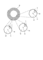
恒久ねじれについて、図2に例示した増幅用光ファイバ10を参照しながら説明する。
恒久ねじれについて、図2に例示した増幅用光ファイバ10を参照しながら説明する。
図2の例において、増幅用光ファイバ10は、コア11と、コア11の外側を覆う第一クラッド12と、第一クラッド12の外側を覆う第2クラッド13と、を有するダブルクラッド光ファイバである。増幅用光ファイバ10の長手方向に垂直な断面において、第一クラッド12の断面は正7角形(非円形クラッド)である。
第一クラッド12と第2クラッド13との境界が2回軸対称でない正7角形であるため、クラッドを導波してコアに到達せず、励起光として寄与しない光、いわゆるスキュー光を抑制することができる。しかしながら、第一クラッド12の断面形状を多角形にしただけでは、依然としてスキュー光が残る。スキュー光をさらに低減し、励起光の利用効率をさらに向上させるために、増幅用光ファイバ10は、増幅用光ファイバ10の中心軸を中心として周方向にねじられるように巻回されている。
増幅用光ファイバ10がねじられているため、第一クラッド12の正7角形の向きが増幅用光ファイバ10の場所によって異なる。そのため、図2に示すように、スキュー光Lの入射角θ1,θ2,θ3(反射角)は、場所によって変化する。すなわち、θ1≠θ2≠θ3である。この入射角および反射角の変化により、スキュー光Lは、第一クラッド12内を進むうちにコア11に入射するようになり、励起光として寄与する。これにより、励起光の利用効率を上げることができ、出力光のパワーを高めることができる。
増幅用光ファイバ10のねじれ量が多すぎると、ビーム品質が低下するという問題が生じる。増幅用光ファイバ10のねじれ量は、3回転/m以下であることが好ましい。この場合、ビーム品質の劣化、具体的にはM2値の上昇を抑えることができる。M2値は、ガウスビームからのずれを定量的に示す指標であり、回折限界の何倍までビームを絞ることができるかを示す。
増幅用光ファイバ10の全長にわたってねじれ量が一定であってもよい。もしくは、増幅用光ファイバ10のねじれ量を、第一反射部21に近づくにつれて大きくなるように設定してもよい。
増幅用光ファイバ10の全長にわたってねじれ量が一定であってもよい。もしくは、増幅用光ファイバ10のねじれ量を、第一反射部21に近づくにつれて大きくなるように設定してもよい。
増幅用光ファイバ10は、複数のモードの光を伝播可能なヒューモードファイバであり、増幅用光ファイバ10の最内周の少なくとも一部は、所定のモードよりも高次のモード光が増幅用光ファイバのコアからクラッドに漏洩するように曲げられていてもよい。
ファイバレーザの高出力化の一つの方法として複数のモード(ヒューモード)を伝播可能なファイバを増幅用光ファイバとして用いることが知られている。たとえば、増幅用光ファイバ10としてヒューモードファイバを用い、LP01モード及びLP11モードのみを所定のモードとして出力する光部品1において、LP11モードよりも高次のモードは不要である。
ファイバレーザの高出力化の一つの方法として複数のモード(ヒューモード)を伝播可能なファイバを増幅用光ファイバとして用いることが知られている。たとえば、増幅用光ファイバ10としてヒューモードファイバを用い、LP01モード及びLP11モードのみを所定のモードとして出力する光部品1において、LP11モードよりも高次のモードは不要である。
上述した構成によれば、増幅用光ファイバ10の最内周において、必要とするモード(たとえば、LP01モード、LP11モード)を適切に伝播しつつ、不要とするモード(LP11モードよりも高次のモード)を除去することができる。
ファイバレーザの出力向上を妨げる要因の一つとしてしられているTMI(Transverse Mode Instability)は、高次モードの光の存在により生ずることが知られている。上述の構成によれば、第一端10aから増幅用光ファイバ10に励起光が入射された際に、高次モードの光が発生する接続点F1の直後で高次モードの光を低減できる。よって、増幅用光ファイバ10におけるTMI現象の発生を効果的に抑制することができる。
ファイバレーザの出力向上を妨げる要因の一つとしてしられているTMI(Transverse Mode Instability)は、高次モードの光の存在により生ずることが知られている。上述の構成によれば、第一端10aから増幅用光ファイバ10に励起光が入射された際に、高次モードの光が発生する接続点F1の直後で高次モードの光を低減できる。よって、増幅用光ファイバ10におけるTMI現象の発生を効果的に抑制することができる。
第一ファイバ20は、希土類元素をドーパントして実質的に含んでいなくてもよい。第一反射部21は、図1に例示するように、巻回された増幅用光ファイバ10の外側に配されていてもよい。この場合、所定の長さを有する増幅用光ファイバ10をより密に配置することができる。希土類元素をドーパントして実質的に含んでいない第一ファイバ20は、増幅用光ファイバ10に比べて発熱を生じにくい。このため、図1に例示するように、第一ファイバ20を増幅用光ファイバ10により形成されるコイルに交差するように配置しても、光部品1全体としての放熱効果を実質的に維持することができる。
図3は、一実施形態に係るレーザ装置2を示す概略図である。
レーザ装置2は、上述した光部品1と、複数の励起光源41と、前方コンバイナ(コンバイナ)43と、を備えている。
レーザ装置2は、上述した光部品1と、複数の励起光源41と、前方コンバイナ(コンバイナ)43と、を備えている。
各励起光源41は、たとえば、レーザダイオードである。レーザダイオードの一例として、GaAs系半導体を材料とするファブリペロー型半導体レーザが挙げられる。
各励起光源41は、光ファイバ42に接続されている。各励起光源41から射出される励起光は、光ファイバ42を例えばマルチモード光として伝播する。
各光ファイバ42は、前方コンバイナ43に接続されている。前方コンバイナ43は、複数の励起光源41から射出される複数の励起光を結合し、1つの励起光を生成する。前方コンバイナ43は、光部品1の第一ファイバ20に接続されている。
各励起光源41は、光ファイバ42に接続されている。各励起光源41から射出される励起光は、光ファイバ42を例えばマルチモード光として伝播する。
各光ファイバ42は、前方コンバイナ43に接続されている。前方コンバイナ43は、複数の励起光源41から射出される複数の励起光を結合し、1つの励起光を生成する。前方コンバイナ43は、光部品1の第一ファイバ20に接続されている。
前方コンバイナ43で生成された励起光は、第一ファイバ20を介して、増幅用光ファイバ10に導入される。希土類元素がドープされた増幅用光ファイバ10では、励起光が希土類元素に吸収されて反転分布が形成される。反転分布の形成により誘導放出光が発生し、誘導放出光は第一ファイバ20の第一反射部21及び第二ファイバ30の第二反射部31の間で増幅される。
第二ファイバ30は、図3に例示するように、接続点F4においてデリバリファイバ50に接続されている。第一反射部21及び第二反射部31の間で増幅された光がレーザ光としてデリバリファイバ50に供給される。
第二ファイバ30は、図3に例示するように、接続点F4においてデリバリファイバ50に接続されている。第一反射部21及び第二反射部31の間で増幅された光がレーザ光としてデリバリファイバ50に供給される。
本実施形態に係るレーザ装置2によれば、上述した実施形態に係る光部品1を備えているため、上述した光部品1の構成により得られる効果を同様に得ることができる。
レーザ装置2において、前方コンバイナ43が接続される第一ファイバ20の第一反射部21がHR-FBGであり、第二反射部31は第一反射部21よりも反射率が低いOC-FBGであってもよい。
前方コンバイナ43で生成された励起光を、接続点F1を経て増幅用光ファイバ10に入射する場合、接続点F1において生じる不要な高次モードの光を、曲率半径が最も小さい増幅用光ファイバ10の最内周で効率的に除去できる。すなわち、増幅用光ファイバ10の入射端(第一端10a)付近で不要な高次モードの光を効率的に除去できる。
したがって、増幅用光ファイバ10における発熱を低減することができる。特に、図3に例示したような端面励起方式のレーザ装置において有効である。
前方コンバイナ43で生成された励起光を、接続点F1を経て増幅用光ファイバ10に入射する場合、接続点F1において生じる不要な高次モードの光を、曲率半径が最も小さい増幅用光ファイバ10の最内周で効率的に除去できる。すなわち、増幅用光ファイバ10の入射端(第一端10a)付近で不要な高次モードの光を効率的に除去できる。
したがって、増幅用光ファイバ10における発熱を低減することができる。特に、図3に例示したような端面励起方式のレーザ装置において有効である。
図4は、一実施形態に係るレーザ装置3を示す概略図である。上記レーザ装置2と同じ構造を有する要素については、説明を省略する。
レーザ装置3は、上記レーザ装置2と同様に、上述した光部品1と、複数の励起光源41と、前方コンバイナ43と、を備えている。上記レーザ装置2と異なり、レーザ装置3は、第二ファイバ30とデリバリファイバ50との間に、後方コンバイナ(コンバイナ)44をさらに備えている。後方コンバイナ44は、光ファイバ42を介して複数の励起光源41に接続されている。
後方コンバイナ44は、複数の励起光源41から射出される複数の励起光を結合し、1つの励起光を生成する。後方コンバイナ44は、光部品1の第二ファイバ30に接続されている。
後方コンバイナ44は、複数の励起光源41から射出される複数の励起光を結合し、1つの励起光を生成する。後方コンバイナ44は、光部品1の第二ファイバ30に接続されている。
後方コンバイナ44で生成された励起光も、第二ファイバ30を介して、増幅用光ファイバ10に導入される。希土類元素がドープされた増幅用光ファイバ10では、前方コンバイナ43及び後方コンバイナ44から導入された励起光が希土類元素に吸収されて反転分布が形成される。反転分布の形成により誘導放出光が発生し、誘導放出光は第一ファイバ20の第一反射部21及び第二ファイバ30の第二反射部31の間で増幅される。
本実施形態に係るレーザ装置3によれば、上述した実施形態に係る光部品1を備えているため、上述した光部品1の構成により得られる効果を同様に得ることができる。
レーザ装置3において、前方コンバイナ43が接続される第一ファイバ20の第一反射部21がHR-FBGであり、第二反射部31は第一反射部21よりも反射率が低いOC-FBGであってもよい。
前方コンバイナ43で生成された励起光を、接続点F1を経て増幅用光ファイバ10に入射する場合、接続点F1において生じる不要な高次モードの光を、曲率半径が最も小さい増幅用光ファイバ10の最内周で効率的に除去できる。すなわち、増幅用光ファイバ10の入射端(第一端10a)近傍で不要な高次モードの光を効率的に除去できる。
したがって、増幅用光ファイバ10における発熱を低減することができる。特に、図4に例示したような端面励起方式のレーザ装置において有効である。
前方コンバイナ43で生成された励起光を、接続点F1を経て増幅用光ファイバ10に入射する場合、接続点F1において生じる不要な高次モードの光を、曲率半径が最も小さい増幅用光ファイバ10の最内周で効率的に除去できる。すなわち、増幅用光ファイバ10の入射端(第一端10a)近傍で不要な高次モードの光を効率的に除去できる。
したがって、増幅用光ファイバ10における発熱を低減することができる。特に、図4に例示したような端面励起方式のレーザ装置において有効である。
また、後方コンバイナ44で生成された励起光も増幅用光ファイバ10に導入できる(双方向励起)。したがって、上述したように前方コンバイナ43から入射された励起光による増幅用光ファイバ10の発熱を抑制しつつ、より高出力なレーザ装置を提供できる。
以上、本発明の好ましい実施形態を記載し説明してきたが、これらは本発明の例示的なものであり、限定するものとして考慮されるべきではないことを理解すべきである。追加、省略、置換、およびその他の変更は、本発明の範囲から逸脱することなく行うことができる。従って、本発明は、前述の説明によって限定されていると見なされるべきではなく、請求の範囲によって制限されている。
本発明のいくつかの態様によれば、増幅用光ファイバで発生する熱により被るダメージを低減できる光部品およびレーザ装置を提供できる。
1…光部品
2,3…レーザ装置
10…増幅用光ファイバ
10a…第一端
10b…第二端
20…第一ファイバ
21…第一反射部
30…第二ファイバ
31…第二反射部
F1,F2…接続点
41…励起光源
43…前方コンバイナ
44…後方コンバイナ
2,3…レーザ装置
10…増幅用光ファイバ
10a…第一端
10b…第二端
20…第一ファイバ
21…第一反射部
30…第二ファイバ
31…第二反射部
F1,F2…接続点
41…励起光源
43…前方コンバイナ
44…後方コンバイナ
Claims (7)
- 第一反射部を有する第一ファイバと、
第二反射部を有する第二ファイバと、
前記第一ファイバに接続される第一端および前記第二ファイバに接続される第二端を有する増幅用光ファイバと、
を備える光部品であって、
前記増幅用光ファイバは、一平面上で交差しないように且つ前記第一端が最内周に位置するように巻回されている、光部品。 - 前記第一反射部の反射率が前記第二反射部の反射率よりも高い、請求項1に記載の光部品。
- 前記増幅用光ファイバの曲率半径の最小値は、前記増幅用光ファイバ内を伝播するビーム品質を悪化させず且つ、前記増幅用光ファイバの機械的信頼性を満たす曲率半径の2倍以下である、請求項1または2に記載の光部品。
- 前記増幅用光ファイバに恒久ねじれが付与されている、請求項1~3のいずれか一項に記載の光部品。
- 前記増幅用光ファイバは、複数のモードの光を伝播可能なヒューモードファイバであり、
前記増幅用光ファイバの最内周の少なくとも一部は、所定のモードよりも高次のモード光が前記増幅用光ファイバのコアからクラッドに漏洩するように曲げられている、請求項1~4のいずれか一項に記載の光部品。 - 前記第一ファイバは、希土類元素をドーパントして含んでおらず、
前記第一反射部は、前記巻回された増幅用光ファイバの外側に配されている、請求項1~5のいずれか一項に記載の光部品。 - 請求項1~6のいずれか一項に記載の光部品と、
複数の励起光源と、
前記複数の励起光源から射出される複数の励起光を結合し、1つの励起光を生成するコンバイナと、
を備えるレーザ装置であって、
前記コンバイナは、前記光部品の前記第一ファイバに接続されている、レーザ装置。
Applications Claiming Priority (2)
| Application Number | Priority Date | Filing Date | Title |
|---|---|---|---|
| JP2019-029365 | 2019-02-21 | ||
| JP2019029365A JP2020136525A (ja) | 2019-02-21 | 2019-02-21 | 光部品およびレーザ装置 |
Publications (1)
| Publication Number | Publication Date |
|---|---|
| WO2020170558A1 true WO2020170558A1 (ja) | 2020-08-27 |
Family
ID=72143837
Family Applications (1)
| Application Number | Title | Priority Date | Filing Date |
|---|---|---|---|
| PCT/JP2019/048032 Ceased WO2020170558A1 (ja) | 2019-02-21 | 2019-12-09 | 光部品およびレーザ装置 |
Country Status (2)
| Country | Link |
|---|---|
| JP (1) | JP2020136525A (ja) |
| WO (1) | WO2020170558A1 (ja) |
Families Citing this family (1)
| Publication number | Priority date | Publication date | Assignee | Title |
|---|---|---|---|---|
| JP2023121215A (ja) * | 2022-02-21 | 2023-08-31 | 株式会社フジクラ | ファイバレーザ装置 |
Citations (8)
| Publication number | Priority date | Publication date | Assignee | Title |
|---|---|---|---|---|
| JPS59195891A (ja) * | 1983-04-20 | 1984-11-07 | Matsushita Electric Ind Co Ltd | 光フアイバ−を用いたレ−ザ−装置 |
| JP2003248139A (ja) * | 2002-02-26 | 2003-09-05 | Furukawa Electric Co Ltd:The | 光コネクタ用フェルール、光コネクタおよび光コネクタ組立方法 |
| JP2012074603A (ja) * | 2010-09-29 | 2012-04-12 | Furukawa Electric Co Ltd:The | 光ファイバレーザモジュール |
| JP2014165461A (ja) * | 2013-02-27 | 2014-09-08 | Fujikura Ltd | 光増幅部品及びファイバレーザ装置 |
| US9325151B1 (en) * | 2015-03-27 | 2016-04-26 | Ofs Fitel, Llc | Systems and techniques for compensation for the thermo-optic effect in active optical fibers |
| WO2016129447A1 (ja) * | 2015-02-12 | 2016-08-18 | 株式会社フジクラ | ファイバレーザ装置および増幅用コイルの製造方法 |
| US20180205196A1 (en) * | 2017-01-19 | 2018-07-19 | Ofs Fitel, Llc | Gain fiber for high power lasers and amplifiers |
| JP2018190834A (ja) * | 2017-05-08 | 2018-11-29 | 株式会社フジクラ | マルチモードファイバ、光増幅器、及びファイバレーザ |
-
2019
- 2019-02-21 JP JP2019029365A patent/JP2020136525A/ja active Pending
- 2019-12-09 WO PCT/JP2019/048032 patent/WO2020170558A1/ja not_active Ceased
Patent Citations (8)
| Publication number | Priority date | Publication date | Assignee | Title |
|---|---|---|---|---|
| JPS59195891A (ja) * | 1983-04-20 | 1984-11-07 | Matsushita Electric Ind Co Ltd | 光フアイバ−を用いたレ−ザ−装置 |
| JP2003248139A (ja) * | 2002-02-26 | 2003-09-05 | Furukawa Electric Co Ltd:The | 光コネクタ用フェルール、光コネクタおよび光コネクタ組立方法 |
| JP2012074603A (ja) * | 2010-09-29 | 2012-04-12 | Furukawa Electric Co Ltd:The | 光ファイバレーザモジュール |
| JP2014165461A (ja) * | 2013-02-27 | 2014-09-08 | Fujikura Ltd | 光増幅部品及びファイバレーザ装置 |
| WO2016129447A1 (ja) * | 2015-02-12 | 2016-08-18 | 株式会社フジクラ | ファイバレーザ装置および増幅用コイルの製造方法 |
| US9325151B1 (en) * | 2015-03-27 | 2016-04-26 | Ofs Fitel, Llc | Systems and techniques for compensation for the thermo-optic effect in active optical fibers |
| US20180205196A1 (en) * | 2017-01-19 | 2018-07-19 | Ofs Fitel, Llc | Gain fiber for high power lasers and amplifiers |
| JP2018190834A (ja) * | 2017-05-08 | 2018-11-29 | 株式会社フジクラ | マルチモードファイバ、光増幅器、及びファイバレーザ |
Also Published As
| Publication number | Publication date |
|---|---|
| JP2020136525A (ja) | 2020-08-31 |
Similar Documents
| Publication | Publication Date | Title |
|---|---|---|
| JP4243327B2 (ja) | フォトニックバンドギャップファイバ及びファイバ増幅器 | |
| US8498044B2 (en) | Amplification optical fiber, and optical fiber amplifier and resonator using the same | |
| JP5238509B2 (ja) | フォトニックバンドギャップファイバ | |
| JP5260885B2 (ja) | 光ファイバの漏洩光処理構造 | |
| US11114811B2 (en) | Multimode fiber, optical amplifier, and fiber laser | |
| US9431787B2 (en) | Amplification optical fiber and fiber laser device using the same | |
| JP6668272B2 (ja) | 増幅用光ファイバ | |
| JP6511235B2 (ja) | ファイバレーザ装置 | |
| JP6744074B2 (ja) | 光ファイバグレーティング用光ファイバおよびファイバレーザ装置 | |
| US12438330B2 (en) | Optical device and fiber laser apparatus | |
| JP7300512B2 (ja) | 光増幅装置 | |
| JP2011124460A (ja) | 光ファイバ出射回路及びファイバレーザ | |
| JP2020136525A (ja) | 光部品およびレーザ装置 | |
| JP7804482B2 (ja) | ファイバレーザ装置 | |
| JP7429808B2 (ja) | 希土類添加ファイバ及びファイバレーザ装置 | |
| JP4873645B2 (ja) | 光ファイバラマンレーザ装置 | |
| WO2019172398A1 (ja) | 余剰光除去装置及びファイバレーザ | |
| US20210265799A1 (en) | Active waveguide for high-power laser | |
| WO2020203136A1 (ja) | ファイバレーザ装置 | |
| JP7441129B2 (ja) | ファイバレーザ装置 | |
| JP7495804B2 (ja) | 活性元素添加光ファイバ、共振器、及び、ファイバレーザ装置 | |
| JP5014640B2 (ja) | マルチモードファイバ、光増幅器及びファイバレーザ | |
| JP2009294472A (ja) | 光ファイバ |
Legal Events
| Date | Code | Title | Description |
|---|---|---|---|
| 121 | Ep: the epo has been informed by wipo that ep was designated in this application |
Ref document number: 19916340 Country of ref document: EP Kind code of ref document: A1 |
|
| NENP | Non-entry into the national phase |
Ref country code: DE |
|
| 122 | Ep: pct application non-entry in european phase |
Ref document number: 19916340 Country of ref document: EP Kind code of ref document: A1 |