WO2020166684A1 - 眼科装置の点検方法、眼科装置の点検用治具、及び眼科装置 - Google Patents
眼科装置の点検方法、眼科装置の点検用治具、及び眼科装置 Download PDFInfo
- Publication number
- WO2020166684A1 WO2020166684A1 PCT/JP2020/005697 JP2020005697W WO2020166684A1 WO 2020166684 A1 WO2020166684 A1 WO 2020166684A1 JP 2020005697 W JP2020005697 W JP 2020005697W WO 2020166684 A1 WO2020166684 A1 WO 2020166684A1
- Authority
- WO
- WIPO (PCT)
- Prior art keywords
- inspection
- ophthalmologic apparatus
- image
- imaged
- ophthalmic device
- Prior art date
- Legal status (The legal status is an assumption and is not a legal conclusion. Google has not performed a legal analysis and makes no representation as to the accuracy of the status listed.)
- Ceased
Links
Images




Classifications
-
- G—PHYSICS
- G01—MEASURING; TESTING
- G01J—MEASUREMENT OF INTENSITY, VELOCITY, SPECTRAL CONTENT, POLARISATION, PHASE OR PULSE CHARACTERISTICS OF INFRARED, VISIBLE OR ULTRAVIOLET LIGHT; COLORIMETRY; RADIATION PYROMETRY
- G01J3/00—Spectrometry; Spectrophotometry; Monochromators; Measuring colours
- G01J3/46—Measurement of colour; Colour measuring devices, e.g. colorimeters
- G01J3/50—Measurement of colour; Colour measuring devices, e.g. colorimeters using electric radiation detectors
-
- G—PHYSICS
- G06—COMPUTING OR CALCULATING; COUNTING
- G06T—IMAGE DATA PROCESSING OR GENERATION, IN GENERAL
- G06T7/00—Image analysis
- G06T7/0002—Inspection of images, e.g. flaw detection
- G06T7/0004—Industrial image inspection
-
- A—HUMAN NECESSITIES
- A61—MEDICAL OR VETERINARY SCIENCE; HYGIENE
- A61B—DIAGNOSIS; SURGERY; IDENTIFICATION
- A61B3/00—Apparatus for testing the eyes; Instruments for examining the eyes
- A61B3/10—Objective types, i.e. instruments for examining the eyes independent of the patients' perceptions or reactions
- A61B3/101—Objective types, i.e. instruments for examining the eyes independent of the patients' perceptions or reactions for examining the tear film
-
- G—PHYSICS
- G01—MEASURING; TESTING
- G01J—MEASUREMENT OF INTENSITY, VELOCITY, SPECTRAL CONTENT, POLARISATION, PHASE OR PULSE CHARACTERISTICS OF INFRARED, VISIBLE OR ULTRAVIOLET LIGHT; COLORIMETRY; RADIATION PYROMETRY
- G01J3/00—Spectrometry; Spectrophotometry; Monochromators; Measuring colours
- G01J3/46—Measurement of colour; Colour measuring devices, e.g. colorimeters
- G01J3/463—Colour matching
-
- G—PHYSICS
- G06—COMPUTING OR CALCULATING; COUNTING
- G06T—IMAGE DATA PROCESSING OR GENERATION, IN GENERAL
- G06T7/00—Image analysis
- G06T7/90—Determination of colour characteristics
-
- A—HUMAN NECESSITIES
- A61—MEDICAL OR VETERINARY SCIENCE; HYGIENE
- A61B—DIAGNOSIS; SURGERY; IDENTIFICATION
- A61B3/00—Apparatus for testing the eyes; Instruments for examining the eyes
- A61B3/0016—Operational features thereof
- A61B3/0025—Operational features thereof characterised by electronic signal processing, e.g. eye models
-
- G—PHYSICS
- G06—COMPUTING OR CALCULATING; COUNTING
- G06T—IMAGE DATA PROCESSING OR GENERATION, IN GENERAL
- G06T2207/00—Indexing scheme for image analysis or image enhancement
- G06T2207/30—Subject of image; Context of image processing
- G06T2207/30004—Biomedical image processing
- G06T2207/30041—Eye; Retina; Ophthalmic
-
- G—PHYSICS
- G06—COMPUTING OR CALCULATING; COUNTING
- G06T—IMAGE DATA PROCESSING OR GENERATION, IN GENERAL
- G06T2207/00—Indexing scheme for image analysis or image enhancement
- G06T2207/30—Subject of image; Context of image processing
- G06T2207/30108—Industrial image inspection
Definitions
- the present invention relates to an ophthalmologic apparatus inspection method, an ophthalmologic apparatus inspection jig, and an ophthalmologic apparatus.
- Dry eye is an ophthalmological disease caused by a portion of the surface of the cornea exposed to the outside without being protected by the tear film as the tear film covering the surface of the cornea decreases. Since the development of dry eye may be accompanied by severe diseases such as corneal epithelial disorder and conjunctival disorder, appropriate examination/treatment for dry eye is required.
- a tear film observation device that illuminates the eye to be inspected with predetermined inspection light and observes the interference fringes in the tear film (for example, Patent Document 1).
- This tear film observing device can observe the state of the tear surface on the cornea in a non-contact and non-invasive manner, and therefore has an advantage that the test work can be easily performed without giving an excessive physical burden to the subject. Have.
- an ophthalmologic apparatus including an illumination optical system for the eye to be inspected or an imaging optical system for imaging the illuminated eye to be inspected, such as a tear film observation apparatus, for example, depending on the usage environment after purchase of the apparatus
- Changes may occur in the surface or internal state of the optical system elements, or in the positional/angular relationship between the optical system elements.
- each optical system element of an ophthalmologic apparatus is set up very accurately, so that even if a slight change as described above occurs, the state (quality) of the obtained eye image to be inspected may change greatly. Therefore, in the case of such an ophthalmologic apparatus, it is desirable to present an inspection method that can be performed by the user side, for example, regarding the above-mentioned optical system element.
- Patent Document 2 an example of an inspection (calibration) technique for an ophthalmologic apparatus is disclosed in Patent Document 2.
- the technique disclosed in Patent Document 2 includes a reflecting plate disposed near the position of the condensing point of the laser light, and the reflecting plate receives front-side reflected light or back-side reflected light from the reflector due to the laser light to be received by the light receiving means.
- the calibration is performed by measuring scattered light from the reflector when the laser is irradiated on the reflector, which is arranged so as not to be reflected.
- the technique disclosed in Patent Document 2 the information on the scattered light intensity obtained from the inside of the reflector does not directly indicate the information visually appearing in the image such as the geometrical characteristics and color information of the reflector. Therefore, the technique disclosed in Patent Document 2 is not suitable for inspecting an image obtained by the tear film observation device described above.
- the inspection method of the ophthalmologic apparatus Reflected light from the imaged object for inspection illuminated using the illumination optical system of the ophthalmologic apparatus, receiving using the imaging optical system of the ophthalmic apparatus, and imaging the imaged object for inspection, A step of extracting color information from the image of the imaged object for inspection, Comparing the extracted color information and reference information, the color information, a step of determining whether or not a predetermined reference condition is satisfied, It is characterized by including.
- the inspection is performed using the reflected light from the imaged object for inspection, the inspection work and the preparatory work thereof do not involve an excessive burden. Further, since the inspection is performed based on the color information that briefly shows the appearance state of the image of the inspection target imaged at the time of inspection, it is possible to perform the quality determination of the imaging ability in the ophthalmologic apparatus with good reproducibility.
- the method for inspecting an ophthalmologic apparatus according to the present invention is not limited to the tear film observation apparatus, but also an inspection of other ophthalmologic apparatuses including an illumination optical system and an imaging optical system for an object to be inspected, such as a fundus inspection apparatus. It can also be used as a method.
- the reference condition includes a condition as to whether or not at least a hue value (Hue value) of the extracted color information is within a hue value range defined by the reference information.
- the quality of the imaging capability of the ophthalmologic apparatus is determined based on the hue value that can more clearly identify the color difference in the color information of the inspection target image. Thereby, the accuracy of the determination can be further improved.
- Brightness information is extracted from the imaged image of the inspection object, and the extracted brightness information is compared with reference information to determine whether the brightness information satisfies a predetermined reference condition. Is preferably determined.
- the inspection is further performed using the brightness information of the inspection target image, for example, the amount of light reflected from the inspection target is within a predetermined allowable range due to a problem such as a light source for illumination. It is possible to effectively prevent a situation in which the state of the image capturing object for inspection is not properly captured outside. Thereby, the accuracy of the determination can be further improved.
- the inspection method of the ophthalmologic apparatus It is preferable to dispose the inspection object to be inspected at a position facing the objective lens barrel of the ophthalmologic apparatus in which an eye to be inspected is arranged at the time of inspection, and image the inspection object to be imaged.
- the imaged object to be inspected can be imaged close to the state of the eye to be inspected at the time of inspection. .. Thereby, the accuracy of the determination can be further improved.
- the inspection method of the ophthalmologic apparatus it is preferable that an inspection area is cut out from the imaged image and at least color information is extracted from the cut out inspection area.
- the inspection area can be cut out from the image of the inspected image pickup object, so that the comparison with the reference information can be performed accurately. Thereby, the accuracy of the determination can be further improved.
- the inspection jig of the ophthalmologic apparatus according to the present invention Used in the inspection method of the ophthalmic device, The image pickup object for inspection is provided.
- the inspection work and the preparatory work thereof do not involve an excessive burden.
- color information that briefly indicates the reflection characteristics of the inspection target imaged at the time of inspection can be provided from the reflected light of the inspection target image, it is possible to perform reproducibility determination of the imaging capability of the ophthalmologic apparatus with good reproducibility. it can.
- an optical thin film that reflects the illumination light from the illumination optical system is formed on at least the surface of the inspection object.
- the optical thin film is provided on at least the surface, reflected light including color information can be obtained more clearly.
- reflected light including color information can be obtained more clearly.
- the inspection jig of the ophthalmologic apparatus it is preferable that the optical thin film specularly reflects the illumination light.
- the reflected light in the specific wavelength band can be selectively obtained from the optical thin film, so that it can be easily compared with the reference information, for example.
- the optical thin film preferably has a plurality of different thickness portions.
- the reflected light including a plurality of specific wavelength bands can be obtained from the optical thin film, it is possible to increase the variation of the color information that can be selected at the time of comparison with the reference information.
- the inspection jig of the ophthalmologic apparatus further comprising an inspection image pickup object holding portion for holding the inspection image pickup object, It is preferable that the inspection target object holding unit is attached to the tip of the objective lens barrel.
- the imaged object to be inspected can be imaged close to the state of the eye to be inspected at the time of inspection. .. Thereby, the accuracy of the determination can be further improved.
- the ophthalmologic apparatus according to the present invention is characterized by including a jig for inspecting the ophthalmologic apparatus.
- the inspection work and the preparatory work thereof do not involve an excessive burden.
- color information that briefly indicates the reflection characteristics of the inspection target imaged at the time of inspection can be provided from the reflected light of the inspection target image, it is possible to perform reproducibility determination of the imaging capability of the ophthalmologic apparatus with good reproducibility. it can.
- an inspection method for an ophthalmologic apparatus capable of making a good reproducibility determination of the imaging ability of the ophthalmic apparatus. Further, it is possible to provide an inspection jig used when performing the inspection method of the ophthalmologic apparatus, and an ophthalmologic apparatus including the inspection jig.
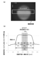
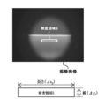
- FIG. 8 is still another diagram used for explaining the procedure of cutting out the inspection region from the imaged image of the inspection object to be imaged according to the present embodiment.
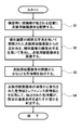
- 6 is a flowchart showing a procedure for cutting out an inspection region from a captured image of the inspection target imaged object according to the present embodiment.
- FIG. 4 is a vertical cross-sectional view of the inspection jig of the ophthalmologic apparatus according to the present embodiment, which is attached to the tip of the objective lens barrel.
- FIG. 3 is a vertical cross-sectional view of the inspected image pickup object according to the embodiment.
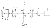
- FIG. 1 is a schematic view of the ophthalmologic apparatus 1.
- the ophthalmologic apparatus 1 includes a light source 11 (a white light source in the present embodiment), a half mirror 12, an objective lens 13, an imaging lens 14, an imaging unit 15, an analyzing device 16, and an inspection jig 20. And so on.
- the ophthalmologic apparatus 1 according to this embodiment is a tear film observation apparatus.
- the invention is not limited to this, and may be another ophthalmologic apparatus such as a fundus examination apparatus.
- the light from the light source 11 is emitted toward the half mirror 12, and part of the light reaching the half mirror 12 is reflected toward the objective lens 13. Further, the light that has passed through the objective lens 13 reaches the inspection target image pickup object 21 attached to the inspection jig 20. As a result, the image pickup object 21 for inspection is illuminated.
- the eye to be inspected is placed at a position where the image pickup object for inspection 21 is placed, and the illumination light passing through the objective lens 13 illuminates the eye to be inspected.
- the inspection subject 21 of the inspection jig 20 is illuminated with illumination light
- the illumination light is reflected from the inspection subject 21 toward the objective lens 13.
- the reflected light passes through the objective lens 13 and the half mirror 12, and is condensed by the imaging lens 14.
- the collected reflected light is received by the image pickup means 15 (for example, a CCD camera, a CMOS camera, etc.) and converted into an electric signal forming image information of the inspection target image pickup object 21.
- the inspection subject 21 is imaged.
- the analysis device 16 includes a processing unit that calculates and processes data, and a storage unit that stores the data.
- the storage unit includes, for example, a program for executing image processing described below and a predetermined unit. Data is stored in each of them, and the processing means processes the data in accordance with a predetermined instruction by the program or the like.
- the analysis device 16 may be a general computer and includes, for example, a CPU, a RAM, a hard disk, an input/output device, a communication unit, and the like.
- an illumination optical system a set of optical elements for illuminating the inspected image pickup object 21 arranged in the optical path from the light source 11 to the inspected image pickup object 21 is called an illumination optical system. That is, in the case of the embodiment shown in FIG. 1, the light source 11, the half mirror 12, and the objective lens 13 are included in the illumination optical system. Other optical elements such as various lenses, mirrors, and filters may be included in the illumination optical system as necessary.
- an image pickup optical system a set of optical elements for capturing an image of the inspected image pickup object 21 arranged in the optical path from the inspected image pickup object 21 to the image pickup means 15 is called an image pickup optical system.
- the objective lens 13, the half mirror 12, the imaging lens 14, and the image pickup means 15 are included in the image pickup optical system.
- Other optical elements such as various lenses, mirrors, and filters may be included in the imaging optical system as necessary.
- FIG. 2 is a flowchart showing the procedure of the inspection method for the ophthalmologic apparatus 1 according to this embodiment.
- the inspection target image pickup object 21 is arranged at a position where the eye to be inspected is arranged during the inspection (for example, a position facing the objective lens barrel of the ophthalmologic apparatus 1) (S1).
- the inspected image pickup object 21 in the present embodiment is held in a state of being housed in the inspected image pickup object holding portion 22 of the inspection jig 20.
- the inspection target image object 21 is arranged at a position where the eye to be inspected is placed during the inspection. ..
- the position of the inspected image pickup object 21 is not limited to this.
- the reflected light from the image-capturing object 21 for inspection illuminated by using the illumination optical system of the ophthalmologic apparatus 1 is received by using the image-capturing optical system of the ophthalmologic apparatus 1, and the image-capturing object 21 for inspection is imaged.
- S2 More specifically, as described above, the inspection target imaging object 21 is illuminated with the illumination light from the light source 11, and the reflected light from the illuminated inspection target imaging object 21 is received by the imaging unit 15. As a result, the inspection subject 21 is imaged, and the image of the inspection subject 21 is recorded in the imaging means 15.
- the image recorded by the image pickup means 15 is transmitted to the analysis device 16, and at least color information is extracted from the image of the inspection target 21 by the image processing executable by the analysis device 16 (S3). More preferably, the hue value is extracted from the image of the inspected image pickup target 21.
- the inspection area may be cut out in advance from the captured image, and the color information may be extracted from the cut out inspection area.
- the method of selecting the inspection region to be cut out is not particularly limited, but for example, the image processing of the analysis device 16 refers to the luminance value and the RGB value of each pixel in the image of the inspection object 21, and the predetermined value is determined. Examples include a method of selecting an image area (inspection area) having a luminance equal to or higher than a threshold and having little color unevenness.
- the cut-out inspection area is hereinafter referred to as "inspection area S".
- the method of cutting out the inspection area S in the present embodiment includes the following Step 1 to Step 4.
- Step 1 The length of the inspection area S is determined.
- Step 2 The width of the inspection area S is determined.
- Step 3 The captured image in the inspection area S is cut out.
- Step 4 The hue value and the lightness of the HSV values of the cut-out captured image are calculated.
- Step 1 is a step of determining the length of the inspection area S.
- the average luminance value in the y-axis direction in the plot area shown in FIG. 3A is obtained (S11 in FIG. 6).
- the result of plotting it on the x-axis coordinate is the graph of FIG. 3(b).
- the horizontal axis of this graph is the x-axis coordinate of the captured image.
- the value on the vertical axis of this graph corresponds to the above-mentioned average luminance value in the y-axis direction.
- a threshold value (50) is set on the vertical axis (S13 in FIG. 6).
- the range of luminance exceeding the threshold value is set as ⁇ x (S14 in FIG. 6).
- This ⁇ x is divided into three equal parts and the central range is cut out to be ⁇ x2 (S15 in FIG. 6).
- This ⁇ x2 corresponds to the length of the inspection area S (S16 in FIG. 6).
- Step 2 is a step of determining the width of the inspection area S.
- the average luminance value in the x-axis direction within the plot area shown in FIG. 4A is obtained (S21 in FIG. 6).
- the result of plotting it on the y-axis coordinate is the graph of FIG. 4(b).
- the vertical axis of this graph is the y-axis coordinate of the image.
- the value on the horizontal axis of this graph corresponds to the average brightness value in the x-axis direction.
- the maximum brightness value is obtained (S23 in FIG. 6).
- y1 corresponds to the maximum luminance value.
- y2 corresponds to the above change point.
- the portion corresponding to the vertical axis of the range between y1 and y2 is set to ⁇ y (S27 in FIG. 6).
- This ⁇ y is divided into three equal parts and the central range is cut out to obtain ⁇ y2 (S28 in FIG. 6).
- this ⁇ y2 corresponds to the width of the inspection area S (S29 in FIG. 6).
- Step 3 a range corresponding to the inspection area S defined above is cut out from the captured image.
- a region corresponding to ⁇ x2 selected in Step 1 and ⁇ y2 selected in Step 2 is cut out from the captured image (S31 in FIG. 6).
- the cut-out image becomes a captured image in the inspection area S.
- Step 4 is a step of calculating the hue value and the lightness of the HSV values of the captured image cut out in the inspection area S.
- An R brightness average value, a G brightness average value, and a B brightness average value in all the regions of the captured image cut out in the inspection region S are calculated (S41 in FIG. 6).
- the value is used to convert to an HSV value (S42 in FIG. 6).
- the hue value and the lightness are acquired from the HSV value (S43 in FIG. 6).
- the conversion from the RGB value to the HSV value can be performed using a known conversion formula shown in, for example, Japanese Patent Laid-Open No. 2019-009752.
- the conversion program stored in the analysis device 16 converts the input color information of each pixel from an RGB value to an HSV (hue, saturation, lightness) value. Further, the color information may further include a color difference value.
- the conversion value from the RGB value is not limited to HSV, and may be a value belonging to another color model such as HSB or HSL.
- the reference information in the present embodiment is the color of the image (hereinafter, referred to as “reference image”) of the inspection-target image-captured object 21 captured using the ophthalmologic apparatus 1 before the shipment of the ophthalmologic apparatus 1.
- reference image the color of the image of the inspection-target image-captured object 21 captured using the ophthalmologic apparatus 1 before the shipment of the ophthalmologic apparatus 1.
- the reference information is not limited to the reference image and may be any information that can be compared with the color information and the like extracted from the image of the inspection target image pickup object 21.
- the hue value of the inspection area S to be inspected is within a predetermined allowable range.
- the hue value of the comparison image area C in the reference image corresponding to the inspection area S is set as the median value, and the value decreased by a predetermined number from that value is set as the lower limit, and the value increased by the predetermined number.
- the numerical range from the lower limit to the upper limit is set as an allowable range. In this case, for example, when the hue value of the comparative image region C is 19° and ⁇ 30% is set as the allowable range (that is, the lower limit of the allowable range is 13.3° and the upper limit is 24.7°).
- the hue value of the inspection area S is 15°, it is determined that the color information extracted from the image of the inspected image pickup object 21 satisfies the reference condition. As a result, it can be confirmed that the image captured by using the ophthalmologic apparatus 1 accurately reflects the state of the object to be imaged. This indicates that the ophthalmologic apparatus 1 has a good photographing ability.
- the image captured using the ophthalmologic apparatus 1 is based on the color information (particularly, the hue value) that briefly shows the state of the image of the inspection target image 21.
- the color information particularly, the hue value
- the inspection target image pickup object 21 is predetermined by a simple work of simply attaching the inspection jig 20 to the tip 31 (shown in FIG. 8) of the objective lens barrel 30 of the ophthalmologic apparatus 1.
- the inspection target image pickup object 21 can be imaged. Therefore, even if the user does not have a special skill regarding inspection, each inspection procedure described above can be easily performed.
- the light quantity of the reflected light received by the image pickup means 15 exceeds the light receiving quantity capacity of the image pickup means 15 and is saturated. It is possible to effectively prevent a situation where an image is not accurately captured. Further, for example, a disturbance light component other than the reflected light from the inspected image-capturing target 21 is incident on the image capturing means 15, and the image brightness of the image is extremely high, so that the state of the image-capturing target image 21 for inspection is not accurately captured. Can be effectively prevented. It should be noted that a predetermined dimming unit capable of adjusting the light amount of the light source 11 and the light receiving amount of the imaging unit 15 may be separately provided.
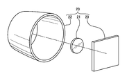
- FIG. 7 is an exploded perspective view of the inspection jig 20.
- FIG. 8 is a vertical cross-sectional view of the inspection jig 20 attached to the tip 31 of the objective lens barrel 30.
- the inspection jig 20 includes the above-described image pickup object for inspection 21 and the image pickup object holding portion 22 for inspection. Further, the inspection jig 20 preferably includes an ND filter 23 that reduces the amount of reflected light from the inspection imaged object 21. The inspected image pickup object 21 and the ND filter 23 are housed in the inspected image pickup object holding portion 22.
- the image capturing object holding portion 22 for inspection in the present embodiment is a bottomed cylindrical body having a top opening, and has a black color.
- ambient light such as room light
- the original RGB values derived from the reflected light from the inspected image pickup object 21 cannot be obtained.
- the reproducibility of the inspection may be impaired due to the influence of the surrounding environment.
- the provision of the inspection target image holding member 22 makes it possible to prevent ambient light from entering the inspection target image 21.
- the original RGB values derived from the reflected light from the inspected image pickup object 21 can always be obtained without being affected by the surrounding environment, so that the reproducibility of the inspection can be improved.
- a mounting surface 221 for mounting the inspection target 21 is formed inside the inspection target holder 22.
- the inspection target image pickup object 21 is held on the mounting surface 221 via an adhesive means such as a double-sided tape.
- a support step 222 for supporting the ND filter 23 is formed inside the inspection target object holding portion 22.
- the side edge of the ND filter 23 is held on the support step 222 via an adhesive means such as a double-sided tape.
- the distal end 31 of the objective lens barrel of the ophthalmologic apparatus 1 is detachably fitted into the top opening of the inspected image pickup object holding portion 22 that holds the inspected image pickup object 21 and the ND filter 23, and the inspection jig is attached. 20 is attached to the objective lens barrel 30 of the ophthalmologic apparatus 1.
- the inspection target object holding portion 22 does not have to be the above-mentioned bottomed black cylindrical body. However, when the inspection target object holding unit 22 is in a form in which the entry of ambient light cannot be completely blocked, it is necessary to separately take measures such as capturing an image of the inspection target object 21 in a dark room environment.
- FIG. 9 is a vertical cross-sectional view of the inspected image pickup object 21.
- the inspected imaging target 21 includes an optical thin film 211 formed on the front surface side and a substrate 212.
- the optical thin film 211 in this embodiment is a vapor deposition film having a thickness of about 100 nm to 200 nm, although not particularly limited thereto.
- illumination light for example, the illumination light is reflected on the front surface and the back surface of the optical thin film 211.
- the respective reflected lights interfere with each other, and the reflected lights in the specific wavelength band are emitted from the optical thin film 211.
- the thickness of the optical thin film 211 and the material of the optical thin film 211 having a desired refractive index are appropriately selected, and for example, a color corresponding to or approximate to the coloration of the interference fringes of the eye to be inspected obtained by using the tear film observation device is used. It is preferable to adjust the wavelength band of reflected light.
- the material of the optical thin film 211 is not particularly limited. Examples include titanium dioxide (TiO 2 ), zirconium dioxide (ZrO 2 ), silicon dioxide (SiO 2 ), and the like. These materials are used for lens coatings, optical filters, etc., and are preferable because they are chemically stable and have a property of not easily changing with time, and are inexpensive and reproducibly produce a desired interference color.
- the film forming means for the optical thin film 211 is not particularly limited, and may be a film forming means belonging to a physical vapor deposition method or a chemical vapor deposition method which has been generally used in the past.
- the optical thin film 211 in this embodiment has a plurality of different thickness portions indicated by reference numerals T1 to T5 in FIG. 9, for example.
- the respective thickness portions are arranged so that the thickness increases from the left to the right of the drawing so that the surface portion has a step shape, but the arrangement mode is not limited to this.
- the optical thin film 211 specularly reflects the illumination light as described above, but the reflection mode of the illumination light is not limited to this.
- the optical thin film 211 may be a light scatterer such as various paints and inks, or may be a mode that scatters and reflects irradiation light.
- light scatterers such as various paints and inks
- various paints, inks, and the like generally tend to easily change with time, even when using such a material that easily changes with time, it is possible to periodically replace the image pickup object 21 for inspection with a new one. The reproducibility of inspection can be maintained.
- the substrate 212 in the present embodiment is made of glass as a mirror-finished object suitable for forming an optical thin film, but is not limited to this.
- the back surface 212B is subjected to rubbing or black coating. It is preferable.
Landscapes
- Engineering & Computer Science (AREA)
- Physics & Mathematics (AREA)
- General Physics & Mathematics (AREA)
- Spectroscopy & Molecular Physics (AREA)
- Health & Medical Sciences (AREA)
- Computer Vision & Pattern Recognition (AREA)
- Theoretical Computer Science (AREA)
- Life Sciences & Earth Sciences (AREA)
- General Health & Medical Sciences (AREA)
- Medical Informatics (AREA)
- Biomedical Technology (AREA)
- Heart & Thoracic Surgery (AREA)
- Ophthalmology & Optometry (AREA)
- Molecular Biology (AREA)
- Surgery (AREA)
- Animal Behavior & Ethology (AREA)
- Biophysics (AREA)
- Public Health (AREA)
- Veterinary Medicine (AREA)
- Quality & Reliability (AREA)
- Eye Examination Apparatus (AREA)
- Nuclear Medicine, Radiotherapy & Molecular Imaging (AREA)
- Radiology & Medical Imaging (AREA)
Abstract
本発明は、涙液層観察装置のような被検眼を撮像する眼科装置の点検を行うにあたり各器材の調整に過度な作業負担を伴うことなく、且つ撮像された画像が被撮像体の状態を適確に現すものか否かに係る撮影能力の良否判定を再現性良く行うことができる眼科装置の点検方法、点検用治具、及び眼科装置の提供を目的とする。 本発明に係る眼科装置の点検方法は、眼科装置の照明光学系を用いて照明された点検用被撮像体からの反射光を、前記眼科装置の撮像光学系を用いて受光し、前記点検用被撮像体を撮像し、撮像された前記点検用被撮像体の画像から色情報を抽出し、抽出された前記色情報とレファレンス用情報とを比較して、前記色情報が、所定の基準条件を満たすか否かを判定する。また、本発明に係る眼科装置の点検用治具は、前記点検方法に用いられる。更に、本発明に係る眼科装置は、前記点検用治具を備える。
Description
本発明は、眼科装置の点検方法、眼科装置の点検用治具、及び眼科装置に関する。
スマートフォンやタブレット端末などの携帯型情報端末の普及により、所謂ドライアイを発症したドライアイ患者数が急増している。ドライアイは、角膜表面を覆う涙液層の減少に伴い、一部の角膜表面部分が涙液層に保護されずに外部に露出することに起因する眼科疾患である。ドライアイを発症することで、角膜上皮障害、結膜障害等の重度な疾患を併発する場合もあるため、ドライアイに対する適切な検査・治療が求められる。
ドライアイ用検査装置の一つとして、被検眼に所定の検査光を照明し、涙液層での干渉縞を観察する涙液層観察装置が挙げられる(例えば、特許文献1)。この涙液層観察装置は、非接触・非侵襲で角膜上の涙液面の状態を観察できることから、被検者に過度な身体的負担を与えず、且つ検査作業を容易に行えるという利点を有する。
ところで、涙液層観察装置のような、被検眼への照明光学系や照明された被検眼を撮像する撮像光学系を備えた眼科装置の場合、例えば、装置購入後の使用環境等によって、各光学系要素の表面や内部状態、あるいは各光学系要素間の位置・角度関係に変化が生じ得る。一般に眼科装置の各光学系要素は、非常に精密にセットアップされているため、前記のような変化が僅かでも生じた場合、得られる被検眼画像の状態(質)も大きく変わり得る。従って、このような眼科装置の場合、例えば前記した光学系要素に関して、ユーザー側でも実施可能な点検方法を提示することが望ましい。
ここで、眼科装置の点検(校正)技術の一例が、特許文献2に開示されている。特許文献2に示される技術は、レーザー光の集光点の位置近傍に配置される反射板を備え、反射板は、レーザー光による反射板からの表面反射光または裏面反射光が受光手段に受光されることのないように配置され、レーザー光を反射板に照射したときの反射板からの散乱光を測定することにより校正が行なわれる。
しかしながら、特許文献2に開示の技術において、前記反射板内部から得られる散乱光強度の情報は、反射板の形状的特徴や色情報といった画像に視覚的に現れる情報を直接示すものではない。そのため、特許文献2に開示の技術は、前述の涙液層観察装置で得られる画像の点検には不向きである。
また、特許文献2に開示の技術は、反射板内部からの散乱光のみを受光し、反射板表面や裏面からの反射光を受光しないよう、校正に用いる各器材の位置関係等を調整する必要がある。よって、校正を行うまでに相応の手間が掛かる。更に、前記反射板は、被検眼前房の疑似体として機能する部材であるところ、前房内のたんぱく質と同様の散乱特性を備える必要がある。従って、特許文献2に開示の技術の場合、このような特性を有する反射板を特別に準備する必要があり、それに伴い作製コストが増加する。
これらの課題に鑑み、本発明は、涙液層観察装置のような被検眼を撮像する眼科装置の点検を行うにあたり各器材の調整に過度な作業負担を伴うことなく、且つ撮像された画像が被撮像体の状態を適確に反映するものか否かに係る撮影能力の良否判定を再現性良く行うことができる眼科装置の点検方法の提供を目的とする。また、前記眼科装置の点検方法を実施する際に用いられる点検用治具、及び前記点検用治具を備えた眼科装置の提供を目的とする。
前述した課題を解決するため、本発明に係る眼科装置の点検方法は、
眼科装置の照明光学系を用いて照明された点検用被撮像体からの反射光を、前記眼科装置の撮像光学系を用いて受光し、前記点検用被撮像体を撮像するステップと、
撮像された前記点検用被撮像体の画像から色情報を抽出するステップと、
抽出された前記色情報とレファレンス用情報とを比較して、前記色情報が、所定の基準条件を満たすか否かを判定するステップと、
を備えることを特徴とする。
眼科装置の照明光学系を用いて照明された点検用被撮像体からの反射光を、前記眼科装置の撮像光学系を用いて受光し、前記点検用被撮像体を撮像するステップと、
撮像された前記点検用被撮像体の画像から色情報を抽出するステップと、
抽出された前記色情報とレファレンス用情報とを比較して、前記色情報が、所定の基準条件を満たすか否かを判定するステップと、
を備えることを特徴とする。
本発明の前記態様によれば、点検用被撮像体からの反射光を用いて点検を行うため、点検作業及びその準備作業に過度な負担を伴わない。また、点検時に撮像した点検用被撮像体の画像の外観的状態を端的に示す色情報に基づき点検を行うため、眼科装置における前記撮影能力の良否判定を再現性良く行うことができる。なお、本発明に係る眼科装置の点検方法は、涙液層観察装置のみならず、例えば眼底検査装置のような、被検査体への照明光学系や撮像光学系を備える他の眼科装置の点検方法としても利用できる。
また、本発明に係る眼科装置の点検方法は、
前記基準条件に、抽出された前記色情報のうちの少なくとも色相値(Hue値)が、前記レファレンス用情報で規定される色相値の範囲内であるか否かの条件が含まれることが好ましい。
前記基準条件に、抽出された前記色情報のうちの少なくとも色相値(Hue値)が、前記レファレンス用情報で規定される色相値の範囲内であるか否かの条件が含まれることが好ましい。
本発明の前記態様によれば、点検用被撮像体画像の色情報のうち、より明確に色の違いを識別できる色相値に基づいて眼科装置における前記撮影能力の良否判定を行う。これにより、前記判定の精度をより高めることができる。
更に、本発明に係る眼科装置の点検方法は、
撮像された前記点検用被撮像体の画像から明るさ情報を抽出し、抽出された明るさ情報とレファレンス用情報とを比較して、前記明るさ情報が、所定の基準条件を満たすか否かを判定することが好ましい。
撮像された前記点検用被撮像体の画像から明るさ情報を抽出し、抽出された明るさ情報とレファレンス用情報とを比較して、前記明るさ情報が、所定の基準条件を満たすか否かを判定することが好ましい。
本発明の前記態様によれば、更に点検用被撮像体画像の明るさ情報を用いて点検を行うため、例えば、照明用光源等の問題で点検用被撮像体からの反射光量が所定許容範囲外となり、点検用被撮像体の状態が適確に撮像されていないような事態を有効に防ぐことができる。これにより、前記判定の精度をより高めることができる。
更に、本発明に係る眼科装置の点検方法は、
検査時に被検眼が配される、前記眼科装置の対物鏡筒と対向する位置に前記点検用被撮像体を配置し、前記点検用被撮像体を撮像することが好ましい。
検査時に被検眼が配される、前記眼科装置の対物鏡筒と対向する位置に前記点検用被撮像体を配置し、前記点検用被撮像体を撮像することが好ましい。
本発明の前記態様によれば、点検用被撮像体の位置を検査時の被検眼の位置に合せることから、検査時の被検眼の状態に近づけて点検用被撮像体を撮像することができる。これにより、前記判定の精度をより高めることができる。
更に、本発明に係る眼科装置の点検方法は、
撮像された前記画像から検査領域を切り出し、切り出された検査領域から少なくとも色情報を抽出することが好ましい。
撮像された前記画像から検査領域を切り出し、切り出された検査領域から少なくとも色情報を抽出することが好ましい。
本発明の前記態様によれば、点検用被撮像体の画像から検査領域を切り出すことで、レファレンス用情報との比較を精度良く行うことができる。これにより、前記判定の精度をより高めることができる。
また、本発明に係る眼科装置の点検用治具は、
前記眼科装置の点検方法に用いられ、
前記点検用被撮像体を備えることを特徴とする。
前記眼科装置の点検方法に用いられ、
前記点検用被撮像体を備えることを特徴とする。
本発明の前記態様によれば、点検用被撮像体からの反射光を用いて点検を行うため、点検作業及びその準備作業に過度な負担を伴わない。また、点検時に撮像した点検用被撮像体の反射特性を端的に示す色情報を点検用被撮像体の反射光から提供できるため、眼科装置における前記撮影能力の良否判定を再現性良く行うことができる。
更に、本発明に係る眼科装置の点検用治具は、
前記点検用被撮像体の少なくとも表面に、前記照明光学系からの照明光を反射する光学薄膜が形成されることが好ましい。
前記点検用被撮像体の少なくとも表面に、前記照明光学系からの照明光を反射する光学薄膜が形成されることが好ましい。
本発明の前記態様によれば、光学薄膜を少なくとも表面に備えるため、色情報を含む反射光がより明瞭に得られる。これにより、例えば、点検時に撮像した点検用被撮像体の画像と、点検用のレファレンス画像との色情報の違いをより明確に識別することができる。その結果、前記判定の精度をより高めることができる。
更に、本発明に係る眼科装置の点検用治具は、
前記光学薄膜は、前記照明光を鏡面反射することが好ましい。
前記光学薄膜は、前記照明光を鏡面反射することが好ましい。
本発明の前記態様によれば、光学薄膜から特定波長帯の反射光を選択的に得ることができるため、例えば、レファレンス用情報との比較を容易に行うことができる。
更に、本発明に係る眼科装置の点検用治具は、
前記光学薄膜は、複数の異なる厚み部分を有することが好ましい。
前記光学薄膜は、複数の異なる厚み部分を有することが好ましい。
本発明の前記態様によれば、光学薄膜から、複数の特定波長帯を含む反射光が得られるため、レファレンス用情報との比較時に選択可能な色情報のバリエーションを増やすことができる。
更に、本発明に係る眼科装置の点検用治具は、
前記点検用被撮像体を保持する点検用被撮像体保持部を更に備え、
前記点検用被撮像体保持部は、前記対物鏡筒の先端に装着されることが好ましい。
前記点検用被撮像体を保持する点検用被撮像体保持部を更に備え、
前記点検用被撮像体保持部は、前記対物鏡筒の先端に装着されることが好ましい。
本発明の前記態様によれば、点検用被撮像体の位置を検査時の被検眼の位置に合せることから、検査時の被検眼の状態に近づけて点検用被撮像体を撮像することができる。これにより、前記判定の精度をより高めることができる。
また、本発明に係る眼科装置は、前記眼科装置の点検用治具を備えることを特徴とする。
本発明の前記態様によれば、点検用被撮像体からの反射光を用いて点検を行うため、点検作業及びその準備作業に過度な負担を伴わない。また、点検時に撮像した点検用被撮像体の反射特性を端的に示す色情報を点検用被撮像体の反射光から提供できるため、眼科装置における前記撮影能力の良否判定を再現性良く行うことができる。
本発明によれば、涙液層観察装置のような被検眼を撮像する眼科装置の点検を行うにあたり各器材の調整に過度な作業負担を伴わず、且つ撮像された画像が被撮像体の反射特性を適確に反映する反射画像であるため、眼科装置の持つ撮影能力の良否判定を再現性良く行うことができる眼科装置の点検方法を提供できる。また、前記眼科装置の点検方法を実施する際に用いられる点検用治具、及び前記点検用治具を備えた眼科装置を提供できる。
以下、図面を参照して、本発明の実施形態に係る眼科装置、眼科装置の点検方法、及び眼科装置の点検用治具を詳細に説明する。
<眼科装置>
初めに、図1を参照して、本実施形態に係る眼科装置1の構成概略を説明する。ここで、図1は、眼科装置1の概略図である。図1に示されるように、眼科装置1は、光源11(本実施形態では白色光源)、ハーフミラー12、対物レンズ13、結像レンズ14、撮像手段15、解析装置16、点検用治具20等を備える。なお、本実施形態に係る眼科装置1は、涙液層観察装置である。ただし、これに限られるものではなく、例えば、眼底検査装置等の他の眼科装置であってもよい。
初めに、図1を参照して、本実施形態に係る眼科装置1の構成概略を説明する。ここで、図1は、眼科装置1の概略図である。図1に示されるように、眼科装置1は、光源11(本実施形態では白色光源)、ハーフミラー12、対物レンズ13、結像レンズ14、撮像手段15、解析装置16、点検用治具20等を備える。なお、本実施形態に係る眼科装置1は、涙液層観察装置である。ただし、これに限られるものではなく、例えば、眼底検査装置等の他の眼科装置であってもよい。
光源11からの光は、ハーフミラー12に向けて出射され、ハーフミラー12へ至った光の一部が対物レンズ13に向けて反射される。更に、対物レンズ13を通過した光は、点検用治具20に取り付けられる点検用被撮像体21に至る。これにより点検用被撮像体21が照明される。実際の眼科検査時においては、点検用被撮像体21が配される位置に被検眼が配され、対物レンズ13を通過した照明光が、被検眼を照明する。
更に、点検用治具20の点検用被撮像体21に照明光が照射されると、点検用被撮像体21から対物レンズ13へ向けて照明光が反射される。反射光は、対物レンズ13及びハーフミラー12を通過し、結像レンズ14によって集光される。最終的に、集光された反射光は、撮像手段15(例えば、CCDカメラ、CMOSカメラ等)で受光され、点検用被撮像体21の画像情報を形成する電気信号に変換される。これにより、点検用被撮像体21が撮像される。
更に、撮像手段15で撮像された点検用被撮像体21の画像情報は、解析装置16に送信される。ここで、解析装置16は、データを演算および処理する処理手段、及びデータを記憶する記憶手段を備えるものであり、当該記憶手段には、例えば、後述する画像処理を実行するためのプログラムや所定のデータがそれぞれ記憶されており、処理手段は、当該プログラム等による所定の命令に従ってデータの処理を行う。特に限定されるものではないが、解析装置16は、一般的なコンピュータであってよく、例えば、CPU、RAM、ハードディスク、入出力装置、通信手段等を備える。
なお、以下の説明において、光源11から点検用被撮像体21に至る光路内に配置された点検用被撮像体21を照明するための光学要素の集合を照明光学系と言う。すなわち、図1に示される態様の場合、光源11、ハーフミラー12、対物レンズ13が、照明光学系に含まれる。必要に応じて、各種レンズ、ミラー、フィルター等の他の光学要素が、照明光学系に含まれてもよい。
また、点検用被撮像体21から撮像手段15に至る光路内に配置された点検用被撮像体21を撮像するための光学要素の集合を撮像光学系と言う。図1に示される態様の場合、対物レンズ13、ハーフミラー12、結像レンズ14、撮像手段15が、撮像光学系に含まれる。必要に応じて、各種レンズ、ミラー、フィルター等の他の光学要素が、撮像光学系に含まれてもよい。
<眼科装置の点検方法>
次に、図2を参照して、前記した眼科装置1の点検方法を説明する。図2は、本実施形態に係る眼科装置1の点検方法の手順を示すフローチャートである。まず、検査時に被検眼が配される位置(例えば、眼科装置1の対物鏡筒と対向する位置)に点検用被撮像体21を配置する(S1)。
次に、図2を参照して、前記した眼科装置1の点検方法を説明する。図2は、本実施形態に係る眼科装置1の点検方法の手順を示すフローチャートである。まず、検査時に被検眼が配される位置(例えば、眼科装置1の対物鏡筒と対向する位置)に点検用被撮像体21を配置する(S1)。
本実施形態における点検用被撮像体21は、点検用治具20の点検用被撮像体保持部22内に収容された状態で保持される。例えば、点検用被撮像体保持部22を対物鏡筒30の先端31(図8で示される)に装着することで、検査時に被検眼が配される位置に点検用被撮像体21を配置する。なお、点検用被撮像体21の位置は、これに限られるものではない。
次に、眼科装置1の照明光学系を用いて照明された点検用被撮像体21からの反射光を、眼科装置1の撮像光学系を用いて受光し、点検用被撮像体21を撮像する(S2)。より詳しくは、前述のように、光源11からの照明光を用いて点検用被撮像体21を照明し、照明された点検用被撮像体21からの反射光を撮像手段15で受光する。これにより、点検用被撮像体21を撮像し、点検用被撮像体21の画像を撮像手段15に記録する。
次に、撮像手段15で記録された画像を解析装置16へ送信し、解析装置16で実行可能な画像処理により点検用被撮像体21の画像から少なくとも色情報を抽出する(S3)。より好ましくは、点検用被撮像体21の画像から色相値を抽出する。
なお、点検用被撮像体21の画像から色情報を抽出する前に、撮像画像から検査領域を予め切り出し、切り出された検査領域から色情報を抽出してもよい。切り出す検査領域の選択方法は、特に限定されるものではないが、例えば、解析装置16の画像処理によって、点検用被撮像体21の画像における各画素の輝度値及びRGB値を参照し、所定の閾値以上の輝度を有し且つ色むらの少ない画像領域(検査領域)を選択する、などの方法が挙げられる。なお、切り出された検査領域を以下「検査領域S」と言う。
検査領域Sの切り出し方法の一例を以下具体的に説明する(ただし、検査領域Sの切り出し方法は、下記に限られない。)。本実施形態における検査領域Sの切り出し方法は、以下のStep1からStep4を含む。
(1)Step1:検査領域Sの長さを決定する。
(2)Step2:検査領域Sの幅を決定する。
(3)Step3:検査領域Sにおける撮像画像の切り出しを行う。
(4)Step4:切り出した撮像画像のHSV値のうち色相値と明度を算出する。
(1)Step1:検査領域Sの長さを決定する。
(2)Step2:検査領域Sの幅を決定する。
(3)Step3:検査領域Sにおける撮像画像の切り出しを行う。
(4)Step4:切り出した撮像画像のHSV値のうち色相値と明度を算出する。
図3から図5、並びに図6のフローチャートを参照して、上記Step1からStep4の各工程を詳述する。前述のように、Step1は、検査領域Sの長さを決定する工程である。まず、図3(a)に示されるプロットエリア内のy軸方向の平均輝度値を求める(図6のS11)。それをx軸座標にプロットした(図6のS12)結果が、図3(b)のグラフである。このグラフの横軸は、撮像画像のx軸座標である。また、このグラフの縦軸の値は、前記したy軸方向の平均輝度値に対応する。より詳しくは、グラフの縦軸の値は、共通するx軸座標を持つy軸に沿う画素群の輝度値を足し合わせ、それを平均した値である(例えば、プロットエリア内の画素P11(x=a0,y=b1)の輝度値、画素P12(x=a0,y=b2)の輝度値、画素P13(x=a0,y=b3)の輝度値、・・・、画素P1n(x=a0,y=bn)の輝度値を足し合わせ、それを平均した値)。次に縦軸に対して閾値(50とした)を設ける(図6のS13)。閾値を超える輝度の範囲をΔxとする(図6のS14)。このΔxを三等分して、中央の範囲を切り出したものをΔx2とする(図6のS15)。このΔx2が、検査領域Sの長さに相当する(図6のS16)。
次に、Step2は、検査領域Sの幅を決定する工程である。まず図4(a)に示されるプロットエリア内のx軸方向の平均輝度値を求める(図6のS21)。それをy軸座標にプロットした(図6のS22)結果が、図4(b)のグラフである。このグラフの縦軸は画像のy軸座標である。また、このグラフの横軸の値は、前記したx軸方向の平均輝度値に対応する。より詳しくは、グラフの横軸の値は、共通するy軸座標を持つx軸に沿う画素群の輝度値を足し合わせ、それを平均した値である(例えば、プロットエリア内の画素P21(x=a1,y=b0)の輝度値、画素P22(x=a2,y=b0)の輝度値、画素P23(x=a3,y=b0)の輝度値、・・・、画素P2n(x=an,y=b0)の輝度値を足し合わせ、それを平均した値)。次に輝度値が最大となる値を求める(図6のS23)。図4(b)ではy1が輝度の最大値に相当する。次に、プロットエリア内のx軸方向の各RGBの平均値を求める(図6のS24)。それをy軸座標にプロットした(図6のS25)結果が、図4(c)のグラフである。図4(c)のグラフの横軸は、x軸方向に平均化したR輝度、G輝度、B輝度である。グラフの縦軸は、画像のy軸座標である。次にR輝度、G輝度、B輝度の各プロファイルに着目する。プロファイルより、RGBの各輝度値の関係が、R>G>BからR>B>Gに切り替わる変化点を求める(図6のS26)。図4(c)では、y2が前記の変化点に相当する。次に、y1とy2に挟まれる範囲の縦軸に相当する部分をΔyとする(図6のS27)。このΔyを三等分して、中央の範囲を切り出したものをΔy2とする(図6のS28)。図4(d)に示されるように、このΔy2が、検査領域Sの幅に相当する(図6のS29)。
次に、Step3は、上記で定めた検査領域Sに相当する範囲を、撮像画像から切り出す工程である。図5に示すように、Step1で選択したΔx2及びStep2で選択したΔy2に一致する領域を、撮像画像から切り出す(図6のS31)。切り出した画像は、検査領域Sにおける撮像画像となる。
次に、Step4は、検査領域Sで切り出した撮像画像のHSV値のうち色相値と明度を算出する工程である。検査領域Sで切り出した撮像画像の全領域における、R輝度平均値、G輝度平均値、B輝度平均値を算出する(図6のS41)。その値を用いてHSV値へと変換する(図6のS42)。このHSV値より、色相値、明度を取得する(図6のS43)。
なお、RGB値からHSV値への変換は、例えば、特開2019-009752号等で示される公知の変換式を用いて行うことができる。具体的には、解析装置16に記憶される変換プログラムによって、入力された各画素の色情報が、RGB値からHSV(色相、彩度、明度)値に変換される。また、色情報には、更に色差値が含まれていてもよい。ただし、RGB値からの変換値は、HSVに限られず、HSB、HSL等の他の色モデルに属する値であってもよい。
再び図2を参照し、本実施形態に係る点検方法の続く手順を説明する。前述の図2に示されるS3の手順の後、点検用被撮像体21の画像から抽出された色情報とレファレンス用情報とを比較して、抽出された色情報が、所定の基準条件を満たすか否かを判定する(S4)。本実施形態において、このS4に係る手順も解析装置16で処理される。ここで、本実施形態におけるレファレンス用情報は、眼科装置1の出荷前の段階で、当該眼科装置1を用いて撮像された点検用被撮像体21の画像(以下、「レファレンス画像」)の色情報に相当する。ただし、レファレンス用情報は、レファレンス画像に限られず、点検用被撮像体21の画像から抽出された色情報等と比較可能な情報であればよい。
レファレンス画像の色情報と比較する場合、点検対象の前記検査領域Sの例えば色相値が、予め定められる許容範囲内であるか否かが判定される。ここで、許容範囲の設定例として、検査領域Sに対応するレファレンス画像内の比較画像領域Cの色相値を中央値とし、そこから所定数減少した値を下限とすると共に、所定数増加した値を上限とし、当該下限から上限の数値範囲を許容範囲として設定するなどが挙げられる。この場合、例えば、比較画像領域Cの色相値が19°で±30%を許容範囲とする場合(すなわち、許容範囲の下限が13.3°であり、上限が24.7°とする場合)、検査領域Sの色相値が15°であれば、点検用被撮像体21の画像から抽出された色情報が基準条件を満たすと判定される。その結果、眼科装置1を用いて撮像される画像は、被撮像体の状態を適確に反映していることを確認できる。これにより、眼科装置1は、良好な撮影能力を備えていることが示される。
本実施形態によれば、点検用被撮像体21の画像の様子を端的に示す色情報(特に、色相値)に基づき、眼科装置1を用いて撮像される画像が、被撮像体の状態を適確に反映するものか否かを確認するため、眼科装置1における前記撮影能力の良否判定を再現性良く行うことができる。
また、本実施形態によれば、点検用治具20を眼科装置1の対物鏡筒30の先端31(図8で示される)に装着するのみの簡易な作業で点検用被撮像体21を所定の点検位置に配置し、点検用被撮像体21を撮像することができる。そのため、ユーザーが点検に関する特殊技能を有さずとも、前記した各点検手順を簡便に実施することができる。
前記では、レファレンス用情報との比較情報として、点検用被撮像体21の画像から抽出した色情報(色相値)を用いた態様を説明したが、色情報に加えて明るさ情報(明度)を用いてもよい。
色情報に加えて明るさ情報を用いることで、例えば、撮像手段15で受光する反射光の光量が、撮像手段15の受光量容量を超えて飽和した結果、点検用被撮像体21の状態が適確に撮像されない事態を有効に防ぐことができる。また、例えば、点検用被撮像体21からの反射光以外の外乱光成分が撮像手段15に入射され、画像の明度が著しく高いために点検用被撮像体21の状態が適確に撮像されない事態も有効に防げる。なお、光源11の光量や撮像手段15の受光量を調整できる所定の調光手段を別途設けてもよい。
<点検用治具>
次に、図7及び図8を参照して、本実施形態に係る点検用治具20を説明する。ここで、図7は点検用治具20の分解斜視図である。また、図8は、対物鏡筒30の先端31に装着された点検用治具20の垂直断面図である。
次に、図7及び図8を参照して、本実施形態に係る点検用治具20を説明する。ここで、図7は点検用治具20の分解斜視図である。また、図8は、対物鏡筒30の先端31に装着された点検用治具20の垂直断面図である。
図7に示されるように、点検用治具20は、前記した点検用被撮像体21、点検用被撮像体保持部22を備える。更に、点検用治具20は、点検用被撮像体21からの反射光量を低減させるNDフィルター23を備えることが好ましい。点検用被撮像体21とNDフィルター23は、点検用被撮像体保持部22内に収容される。
本実施形態における点検用被撮像体保持部22は、頂部開口の有底円筒体であり黒色を呈する。室内光等の外乱光が点検用被撮像体21に入射してしまうと、点検用被撮像体21からの反射光に由来する本来のRGB値が得られなくなってしまう。この場合、周辺環境の影響によって検査の再現性が損なわれるおそれがある。その点、上記点検用被撮像体保持部22を備えることで、点検用被撮像体21への外乱光の入射を防ぐことができる。これによって、周辺環境に左右されずいつも点検用被撮像体21からの反射光に由来する本来のRGB値を得ることができるため、検査の再現性を向上させることができる。
また、図8に示されるように、点検用被撮像体保持部22の内部に、点検用被撮像体21を載置する載置面221が形成される。特に限定されるものではないが、点検用被撮像体21は、例えば両面テープなどの接着手段を介して載置面221に保持される。
更に、点検用被撮像体保持部22の内部に、NDフィルター23を支持するための支持段222が形成されている。特に限定されるものではないが、NDフィルター23の側端縁は、例えば両面テープなどの接着手段を介して支持段222に保持される。なお、点検用被撮像体21からの反射光が、NDフィルター23に入射する際、入射光の一部が、点検用被撮像体21に向けて再反射されることを防ぐため、NDフィルター23は、斜め姿勢で点検用被撮像体保持部22に収容されることが好ましい。
このように、点検用被撮像体21及びNDフィルター23を保持する点検用被撮像体保持部22の頂部開口に、眼科装置1の対物鏡筒先端31が着脱可能に嵌め込まれ、点検用治具20は、眼科装置1の対物鏡筒30に装着される。
なお、点検用被撮像体保持部22は、前記した有底の黒色円筒体でなくてもよい。ただし、点検用被撮像体保持部22が、外乱光の進入を完全に遮断できない形態である場合、暗室環境で点検用被撮像体21の撮像を行うなど、別途対処が必要である。
次に、図9を参照して、本実施形態に係る点検用被撮像体21を説明する。図9は、点検用被撮像体21の垂直断面図である。図9に示されるように、点検用被撮像体21は、表面側に形成される光学薄膜211と、基板212を備える。
本実施形態における光学薄膜211は、特に限定されるものではないが、100nmから200nm程度の厚みを有する蒸着膜である。この光学薄膜211に照明光が照明されると、例えば、光学薄膜211の表面と裏面で照明光が反射される。その結果、各々の反射光が干渉し、特定波長帯の反射光が光学薄膜211から出射される。光学薄膜211の厚みや、所望の屈折率を有する光学薄膜211の材料を適宜選択し、例えば、涙液層観察装置を用いて得られる被検眼の干渉縞の呈色と対応又は近似する色に、反射光の波長帯を調整することが好ましい。
光学薄膜211の材料は、特に限定されるものではない。一例として、二酸化チタン(TiO2)、二酸化ジルコニウム(ZrO2)、二酸化ケイ素(SiO2)などが挙げられる。これらの材料は、レンズコーティング、光学フィルター等で使用されているもので、化学的に安定で経時変化しにくい性質を有すると共に、安価で、再現良く所望の干渉色が呈色されるため好ましい。また、光学薄膜211の成膜手段も、特に限定されるものではなく、従来から一般に用いられる物理蒸着法に属する成膜手段や化学蒸着法に属する成膜手段等であってよい。
また、本実施形態における光学薄膜211は、例えば、図9の符号T1からT5で示される複数の異なる厚み部分を有することが好ましい。複数の異なる厚み部分を設けることで、各厚み部分から異なる色(波長帯)の反射光を得ることができる。これにより、レファレンス用情報との比較時に選択可能な色情報のバリエーションを増やすことができる。なお、図9では、図の左から右に厚みが増えて表層部分が階段形状となるよう、各厚み部分が配置されているが、配置態様はこれに限られない。
本実施形態に係る光学薄膜211は、前記のように、照明光を鏡面反射するものであるが、照明光の反射態様もこれに限られない。例えば、光学薄膜211は、各種塗料やインク等の光散乱体であってもよく、照射光を散乱反射する態様であってもよい。各種塗料やインク等の光散乱体を利用する場合も、前記と同様、化学的に安定で経時変化しにくい性質の材料を選ぶことが望ましい。なお、各種塗料やインク等は一般的に経時変化し易いものが多いが、このように経時変化し易い材料を用いる場合でも、点検用被撮像体21を定期的に新品と交換することで、検査の再現性を維持することができる。
本実施形態における基板212は、光学薄膜の形成に適した鏡面物体とするガラス製であるが、これに限られない。なお、照明光が、基板212の裏面212Bで反射して、光学薄膜211(点検用被撮像体21)の撮像を阻害する事態を防止するため、裏面212Bにすり加工や黒塗りが施されることが好ましい。
以上、本発明の実施形態を詳細に説明した。ただし、前述の説明は本発明の理解を容易にするためのものであり、本発明を限定する趣旨で記載されたものではない。本発明には、その趣旨を逸脱することなく、変更、改良され得るものを含み得る。また、本発明にはその等価物が含まれる。
1 眼科装置
11 光源
12 ハーフミラー
13 対物レンズ
14 結像レンズ
15 撮像手段
16 解析装置
20 眼科装置の点検用治具
21 点検用被撮像体
211 光学薄膜
212 基板
22 点検用被撮像体保持部
23 NDフィルター
30 対物鏡筒
31 対物鏡筒の先端
11 光源
12 ハーフミラー
13 対物レンズ
14 結像レンズ
15 撮像手段
16 解析装置
20 眼科装置の点検用治具
21 点検用被撮像体
211 光学薄膜
212 基板
22 点検用被撮像体保持部
23 NDフィルター
30 対物鏡筒
31 対物鏡筒の先端
Claims (11)
- 眼科装置の照明光学系を用いて照明された点検用被撮像体からの反射光を、前記眼科装置の撮像光学系を用いて受光し、前記点検用被撮像体を撮像するステップと、
撮像された前記点検用被撮像体の画像から色情報を抽出するステップと、
抽出された前記色情報とレファレンス用情報とを比較して、前記色情報が、所定の基準条件を満たすか否かを判定するステップと、
を備える眼科装置の点検方法。 - 前記基準条件に、抽出された前記色情報のうちの少なくとも色相値が、前記レファレンス用情報で規定される色相値の範囲内であるか否かの条件が含まれる、請求項1に記載の眼科装置の点検方法。
- 更に、撮像された前記点検用被撮像体の画像から明るさ情報を抽出し、抽出された明るさ情報とレファレンス用情報とを比較して、前記明るさ情報が、所定の基準条件を満たすか否かを判定する、請求項1又は2に記載の眼科装置の点検方法。
- 検査時に被検眼が配される、前記眼科装置の対物鏡筒と対向する位置に前記点検用被撮像体を配置し、前記点検用被撮像体を撮像する、請求項1から3のいずれか一項に記載の眼科装置の点検方法。
- 撮像された前記画像から検査領域を切り出し、切り出された検査領域から少なくとも色情報を抽出する、請求項1から4のいずれか一項に記載の眼科装置の点検方法。
- 請求項1から5のいずれか一項に記載の眼科装置の点検方法に用いられ、
前記点検用被撮像体を備える、眼科装置の点検用治具。 - 前記点検用被撮像体の少なくとも表面に、前記照明光学系からの照明光を反射する光学薄膜が形成される、請求項6に記載の眼科装置の点検用治具。
- 前記光学薄膜は、前記照明光を鏡面反射する、請求項7に記載の眼科装置の点検用治具。
- 前記光学薄膜は、複数の異なる厚み部分を有する、請求項7又は8に記載の眼科装置の点検用治具。
- 前記点検用被撮像体を保持する点検用被撮像体保持部を更に備え、
前記点検用被撮像体保持部は、前記対物鏡筒の先端に装着される、請求項6から9のいずれか一項に記載の眼科装置の点検用治具。 - 請求項6から請求項10のいずれか一項に記載の眼科装置の点検用治具を備える、眼科装置。
Priority Applications (3)
| Application Number | Priority Date | Filing Date | Title |
|---|---|---|---|
| JP2020572324A JP7522048B2 (ja) | 2019-02-15 | 2020-02-14 | 眼科装置の点検方法、眼科装置の点検用治具、及び眼科装置 |
| US17/429,298 US20220148179A1 (en) | 2019-02-15 | 2020-02-14 | Method for inspecting ophthalmic device, inspection jig for ophthalmic device, and ophthalmic device |
| CN202080012389.5A CN113382672A (zh) | 2019-02-15 | 2020-02-14 | 眼科装置的检测方法、眼科装置的检测用夹具、及眼科装置 |
Applications Claiming Priority (2)
| Application Number | Priority Date | Filing Date | Title |
|---|---|---|---|
| JP2019-025957 | 2019-02-15 | ||
| JP2019025957 | 2019-02-15 |
Publications (1)
| Publication Number | Publication Date |
|---|---|
| WO2020166684A1 true WO2020166684A1 (ja) | 2020-08-20 |
Family
ID=72044110
Family Applications (1)
| Application Number | Title | Priority Date | Filing Date |
|---|---|---|---|
| PCT/JP2020/005697 Ceased WO2020166684A1 (ja) | 2019-02-15 | 2020-02-14 | 眼科装置の点検方法、眼科装置の点検用治具、及び眼科装置 |
Country Status (4)
| Country | Link |
|---|---|
| US (1) | US20220148179A1 (ja) |
| JP (1) | JP7522048B2 (ja) |
| CN (1) | CN113382672A (ja) |
| WO (1) | WO2020166684A1 (ja) |
Families Citing this family (1)
| Publication number | Priority date | Publication date | Assignee | Title |
|---|---|---|---|---|
| CA3259506A1 (en) * | 2022-08-01 | 2024-02-08 | Alcon Inc. | COLOR CORRECTION IN OPHTHALMIC IMAGING |
Citations (5)
| Publication number | Priority date | Publication date | Assignee | Title |
|---|---|---|---|---|
| JP2001275984A (ja) * | 2000-04-04 | 2001-10-09 | Canon Inc | 眼科撮影装置 |
| JP2002165759A (ja) * | 2000-12-05 | 2002-06-11 | Topcon Corp | 模型眼 |
| JP2009022308A (ja) * | 2007-07-17 | 2009-02-05 | Kowa Co | 画像処理装置 |
| JP2011087651A (ja) * | 2009-10-20 | 2011-05-06 | Canon Inc | 眼科撮影装置の製造方法、検査装置、眼科撮影装置及び撮影ユニット |
| JP2018187018A (ja) * | 2017-05-01 | 2018-11-29 | 株式会社ニデック | 眼科装置 |
Family Cites Families (10)
| Publication number | Priority date | Publication date | Assignee | Title |
|---|---|---|---|---|
| US8929973B1 (en) * | 2005-10-24 | 2015-01-06 | Lockheed Martin Corporation | Apparatus and method for characterizing optical sources used with human and animal tissues |
| JP6066595B2 (ja) * | 2011-07-29 | 2017-01-25 | キヤノン株式会社 | 眼底画像の画像処理装置、眼底画像の画像処理方法、及びプログラム |
| JP6101048B2 (ja) * | 2012-02-20 | 2017-03-22 | キヤノン株式会社 | 画像処理装置及び画像処理方法 |
| WO2013166352A2 (en) | 2012-05-04 | 2013-11-07 | Tearscience, Inc. | Optical phantoms for use with ocular surface interferometry (osi) devices and systems configured to measure tear film layer thickness(es), and related uses for calibration |
| WO2014100678A1 (en) * | 2012-12-21 | 2014-06-26 | Tearscience, Inc. | Full-eye illumination ocular surface imaging of an ocular tear film for determining tear film thickness and/or providing ocular topography |
| JP6141140B2 (ja) * | 2013-08-08 | 2017-06-07 | 株式会社トプコン | 眼科撮影装置 |
| JP6742691B2 (ja) * | 2015-01-30 | 2020-08-19 | キヤノン株式会社 | 眼科装置、画像処理方法およびプログラム |
| JP7050588B2 (ja) * | 2018-06-13 | 2022-04-08 | 株式会社トプコン | 眼科装置、その制御方法、プログラム、及び記録媒体 |
| IL261815B2 (en) * | 2018-09-16 | 2023-05-01 | Adom Advanced Optical Tech Ltd | Device and methods for calibrating optical measurements |
| US20220034713A1 (en) * | 2021-10-14 | 2022-02-03 | Shenzhen Xkool Technology Co., Ltd. | Method and device for real-time measuring sunlight on buildings |
-
2020
- 2020-02-14 US US17/429,298 patent/US20220148179A1/en not_active Abandoned
- 2020-02-14 CN CN202080012389.5A patent/CN113382672A/zh active Pending
- 2020-02-14 WO PCT/JP2020/005697 patent/WO2020166684A1/ja not_active Ceased
- 2020-02-14 JP JP2020572324A patent/JP7522048B2/ja active Active
Patent Citations (5)
| Publication number | Priority date | Publication date | Assignee | Title |
|---|---|---|---|---|
| JP2001275984A (ja) * | 2000-04-04 | 2001-10-09 | Canon Inc | 眼科撮影装置 |
| JP2002165759A (ja) * | 2000-12-05 | 2002-06-11 | Topcon Corp | 模型眼 |
| JP2009022308A (ja) * | 2007-07-17 | 2009-02-05 | Kowa Co | 画像処理装置 |
| JP2011087651A (ja) * | 2009-10-20 | 2011-05-06 | Canon Inc | 眼科撮影装置の製造方法、検査装置、眼科撮影装置及び撮影ユニット |
| JP2018187018A (ja) * | 2017-05-01 | 2018-11-29 | 株式会社ニデック | 眼科装置 |
Also Published As
| Publication number | Publication date |
|---|---|
| CN113382672A (zh) | 2021-09-10 |
| US20220148179A1 (en) | 2022-05-12 |
| JP7522048B2 (ja) | 2024-07-24 |
| JPWO2020166684A1 (ja) | 2021-12-16 |
Similar Documents
| Publication | Publication Date | Title |
|---|---|---|
| US20240341597A1 (en) | Wide Field Fundus Camera with Auto Montage at A Single Alignment | |
| JP5232165B2 (ja) | 眼底カメラ用の光学システム | |
| JP6023406B2 (ja) | 眼科装置、評価方法および当該方法を実行するプログラム | |
| JP6766413B2 (ja) | 眼底撮影装置 | |
| TW202521941A (zh) | 電腦、程式及方法 | |
| EP2395906A1 (en) | Method and apparatus for ocular surface imaging | |
| KR20140116353A (ko) | 알츠하이머 병, 외상성 뇌손상, 시력감퇴, 신경병 및 안질환의 진단과 예측을 위해 망막내 아밀로이드를 감지하는 장치와 방법 | |
| US7819526B2 (en) | Fundus camera | |
| US9872617B2 (en) | Flexible, multimodal retina image recording system and measurement system | |
| JP7376847B2 (ja) | 眼底画像処理装置および眼底画像処理プログラム | |
| JP6720653B2 (ja) | 眼科撮影装置 | |
| JP6901264B2 (ja) | 眼科装置 | |
| US11013401B2 (en) | Ophthalmologic apparatus | |
| JP2020156705A (ja) | 眼科装置及びその制御方法、並びに、プログラム | |
| WO2020166684A1 (ja) | 眼科装置の点検方法、眼科装置の点検用治具、及び眼科装置 | |
| JP2008116900A (ja) | 干渉対物レンズと、その干渉対物レンズを備える干渉顕微鏡装置 | |
| JP5025761B2 (ja) | 画像処理装置、画像処理方法及びプログラム | |
| CN115135227A (zh) | 用于检查眼睛的检眼镜 | |
| JPS61265126A (ja) | 眼底カメラ装置 | |
| CN121548728A (zh) | 用于校准高光谱图像传感器的像素的像素灵敏度的方法和设备 | |
| HK40061575A (en) | Method for inspecting ophthalmic device, inspection jig for ophthalmic device, and ophthalmic device | |
| CN113383220B (zh) | 图像检查装置 | |
| JP6756873B2 (ja) | 眼科撮影装置 | |
| JP4505852B2 (ja) | 眼底分光像撮影装置 | |
| JP2023009720A (ja) | 血中酸素飽和度測定装置 |
Legal Events
| Date | Code | Title | Description |
|---|---|---|---|
| 121 | Ep: the epo has been informed by wipo that ep was designated in this application |
Ref document number: 20756179 Country of ref document: EP Kind code of ref document: A1 |
|
| ENP | Entry into the national phase |
Ref document number: 2020572324 Country of ref document: JP Kind code of ref document: A |
|
| NENP | Non-entry into the national phase |
Ref country code: DE |
|
| 122 | Ep: pct application non-entry in european phase |
Ref document number: 20756179 Country of ref document: EP Kind code of ref document: A1 |