WO2020166601A1 - 活物質 - Google Patents
活物質 Download PDFInfo
- Publication number
- WO2020166601A1 WO2020166601A1 PCT/JP2020/005317 JP2020005317W WO2020166601A1 WO 2020166601 A1 WO2020166601 A1 WO 2020166601A1 JP 2020005317 W JP2020005317 W JP 2020005317W WO 2020166601 A1 WO2020166601 A1 WO 2020166601A1
- Authority
- WO
- WIPO (PCT)
- Prior art keywords
- active material
- negative electrode
- silicon
- less
- mass
- Prior art date
- Legal status (The legal status is an assumption and is not a legal conclusion. Google has not performed a legal analysis and makes no representation as to the accuracy of the status listed.)
- Ceased
Links
Images
Classifications
-
- C—CHEMISTRY; METALLURGY
- C22—METALLURGY; FERROUS OR NON-FERROUS ALLOYS; TREATMENT OF ALLOYS OR NON-FERROUS METALS
- C22C—ALLOYS
- C22C30/00—Alloys containing less than 50% by weight of each constituent
-
- H—ELECTRICITY
- H01—ELECTRIC ELEMENTS
- H01M—PROCESSES OR MEANS, e.g. BATTERIES, FOR THE DIRECT CONVERSION OF CHEMICAL ENERGY INTO ELECTRICAL ENERGY
- H01M10/00—Secondary cells; Manufacture thereof
- H01M10/05—Accumulators with non-aqueous electrolyte
- H01M10/052—Li-accumulators
-
- H—ELECTRICITY
- H01—ELECTRIC ELEMENTS
- H01M—PROCESSES OR MEANS, e.g. BATTERIES, FOR THE DIRECT CONVERSION OF CHEMICAL ENERGY INTO ELECTRICAL ENERGY
- H01M10/00—Secondary cells; Manufacture thereof
- H01M10/05—Accumulators with non-aqueous electrolyte
- H01M10/056—Accumulators with non-aqueous electrolyte characterised by the materials used as electrolytes, e.g. mixed inorganic/organic electrolytes
- H01M10/0561—Accumulators with non-aqueous electrolyte characterised by the materials used as electrolytes, e.g. mixed inorganic/organic electrolytes the electrolyte being constituted of inorganic materials only
- H01M10/0562—Solid materials
-
- H—ELECTRICITY
- H01—ELECTRIC ELEMENTS
- H01M—PROCESSES OR MEANS, e.g. BATTERIES, FOR THE DIRECT CONVERSION OF CHEMICAL ENERGY INTO ELECTRICAL ENERGY
- H01M4/00—Electrodes
- H01M4/02—Electrodes composed of, or comprising, active material
- H01M4/36—Selection of substances as active materials, active masses, active liquids
-
- H—ELECTRICITY
- H01—ELECTRIC ELEMENTS
- H01M—PROCESSES OR MEANS, e.g. BATTERIES, FOR THE DIRECT CONVERSION OF CHEMICAL ENERGY INTO ELECTRICAL ENERGY
- H01M4/00—Electrodes
- H01M4/02—Electrodes composed of, or comprising, active material
- H01M4/36—Selection of substances as active materials, active masses, active liquids
- H01M4/38—Selection of substances as active materials, active masses, active liquids of elements or alloys
-
- H—ELECTRICITY
- H01—ELECTRIC ELEMENTS
- H01M—PROCESSES OR MEANS, e.g. BATTERIES, FOR THE DIRECT CONVERSION OF CHEMICAL ENERGY INTO ELECTRICAL ENERGY
- H01M4/00—Electrodes
- H01M4/02—Electrodes composed of, or comprising, active material
- H01M4/36—Selection of substances as active materials, active masses, active liquids
- H01M4/48—Selection of substances as active materials, active masses, active liquids of inorganic oxides or hydroxides
-
- H—ELECTRICITY
- H01—ELECTRIC ELEMENTS
- H01M—PROCESSES OR MEANS, e.g. BATTERIES, FOR THE DIRECT CONVERSION OF CHEMICAL ENERGY INTO ELECTRICAL ENERGY
- H01M6/00—Primary cells; Manufacture thereof
- H01M6/14—Cells with non-aqueous electrolyte
- H01M6/18—Cells with non-aqueous electrolyte with solid electrolyte
-
- Y—GENERAL TAGGING OF NEW TECHNOLOGICAL DEVELOPMENTS; GENERAL TAGGING OF CROSS-SECTIONAL TECHNOLOGIES SPANNING OVER SEVERAL SECTIONS OF THE IPC; TECHNICAL SUBJECTS COVERED BY FORMER USPC CROSS-REFERENCE ART COLLECTIONS [XRACs] AND DIGESTS
- Y02—TECHNOLOGIES OR APPLICATIONS FOR MITIGATION OR ADAPTATION AGAINST CLIMATE CHANGE
- Y02E—REDUCTION OF GREENHOUSE GAS [GHG] EMISSIONS, RELATED TO ENERGY GENERATION, TRANSMISSION OR DISTRIBUTION
- Y02E60/00—Enabling technologies; Technologies with a potential or indirect contribution to GHG emissions mitigation
- Y02E60/10—Energy storage using batteries
Definitions
- the present invention relates to an active material, a negative electrode using the same, and a solid-state battery.
- the Si-containing active material has a potential that the capacity per mass is 5 to 10 times that of graphite.
- it has a problem that the electron conductivity is not higher than that of graphite. Therefore, in order to increase the electron conductivity of the Si-containing active material, it has been proposed to add a conductive auxiliary agent, for example, for the purpose of imparting electron conductivity between the current collector and the active material.
- Patent Document 1 discloses that the periphery of a core particle containing silicon is coated with a silicon solid solution such as Mg 2 Si, CoSi, or NiSi, and the surface thereof is further coated with a conductive material such as graphite or acetylene black. There is.
- the Si-containing active material also undergoes a large volume change due to the insertion and desorption of lithium ions, and repeats expansion and contraction during charge and discharge cycles, so separation with the conductive auxiliary agent tends to occur as charge and discharge are repeated, and as a result, cycle
- the battery performance is deteriorated and the safety of the battery is deteriorated by causing deterioration of the battery and a decrease in energy density.
- Patent Document 2 discloses active material particles containing silicon and having an average particle diameter of 5 ⁇ m or more and 25 ⁇ m or less. By setting the average particle diameter of the active material particles to 5 ⁇ m or more, the specific surface area of the original active material can be reduced, and thus the contact area between the electrolyte and the new surface of the active material can be reduced. It is described that the suppression effect of is increased.
- an electrode material for a lithium secondary battery which comprises particles of a solid-state alloy containing silicon as a main component, is used as an electrode material having a high efficiency of lithium insertion/desorption.
- an electrode material for a lithium secondary battery characterized in that particles are microcrystalline silicon or amorphized silicon, in which microcrystalline or amorphous particles composed of elements other than silicon are dispersed. ..
- a negative electrode active material for a lithium secondary battery containing silicon, copper and oxygen as main constituent elements having an average crystallite diameter (Dx) measured by Cu 3 Si and an X-ray diffraction method.
- Dx average crystallite diameter measured by Cu 3 Si and an X-ray diffraction method.
- the Si-containing active material causes chemical deterioration due to the electrolyte due to the solid electrolyte containing the silicon and the electrolyte, especially a sulfide-containing solid electrolyte (referred to as “sulfide solid electrolyte”), and inhibits the charge/discharge reaction on the surface of the active material.
- a sulfide-containing solid electrolyte referred to as “sulfide solid electrolyte”
- rate characteristics and cycle characteristics are deteriorated.
- charging/discharging characteristics in a high current range are also required. That is, it is important that the battery has a high rate characteristic, and improvement of the rate characteristic is required.
- the present invention can improve the cycle characteristics of the Si-containing active material, further reduce or eliminate the plateau region in the discharge profile, and further, discharge at a high rate while maintaining the profile. It aims to provide a new active material.
- the present invention relates to silicon, SiO a (0 ⁇ a ⁇ 2), and a chemical formula M x Si y (where x and y satisfy 0.1 ⁇ x/y ⁇ 7.0, and M is Si. And a compound represented by one or more of metalloid elements other than the above and metal elements).
- the content of M in the active material is more than 5% by mass and less than 38% by mass,
- An active material having a ratio of I ⁇ and I ⁇ (I ⁇ /I ⁇ ) of 2.5 or less is proposed.
- the active material proposed by the present invention can be used as a negative electrode active material.
- the active material of the present invention can be used in batteries such as liquid batteries and solid batteries, and can be preferably used in solid batteries.
- the active material of the present invention is advantageously used in a solid battery containing a sulfide solid electrolyte as the solid electrolyte.
- the solid-state battery using the active material of the present invention can have improved cycle characteristics and high rate characteristics. Moreover, the plateau region in the discharge profile can be reduced or eliminated.
- the active material proposed by the present invention not only exhibits the effect in a single use, but, for example, in combination with a carbon material (Graphite), a battery, particularly a solid battery, a solid secondary battery such as a solid lithium secondary battery among them. It can be suitably used as a negative electrode active material of a secondary battery.
- the active material proposed by the present invention contains a certain amount of SiO a (0 ⁇ a ⁇ 2) in addition to silicon and the compound represented by the chemical formula M x Si y , so that chemical degradation caused by the electrolyte is caused. Can be suppressed, and both rate characteristics and durability can be improved.
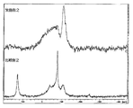
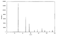
- FIG. 9 is a 29 Si-NMR spectrum of the active materials obtained in Example 2 and Comparative Example 2. It is a diffraction pattern figure of the silicon powder material which is a standard sample for X-ray diffraction made from NIST.
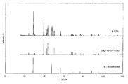
- FIG. 7 is a diagram comparing and comparing the diffraction patterns of the sample obtained in Reference Example 1, ICDD card numbers: 00-005-0565 (chemical formula: Si) and 01-071-0187 (chemical formula: TiSi 2 ) cards. ..
- the active material according to an example of the present embodiment includes silicon, SiO a (0 ⁇ a ⁇ 2), and a chemical formula M x Si y (where x and y are 0). 1 ⁇ x/y ⁇ 7.0, and M is one or more of metalloid elements other than Si and metal elements). is there.
- silicon also means Si capable of inserting and releasing lithium ions. That is, the present active material has a function as an active material by containing silicon.
- silicon mainly refers to pure silicon, but may contain an element that forms a solid solution with Si to form a solid solution. In this case, the solid solution may have a function as an active material.
- the proportion of silicon in the main active material is preferably 30 wt% or more of the main active material, more preferably 40 wt% or more, and even more preferably 50 wt% or more.
- silicon is preferably the main component of the active material in order for the proportion of silicon to affect the charge/discharge capacity and increase the charge/discharge capacity.
- the proportion of silicon in the substance is preferably 50 wt% or more, and particularly preferably 60 wt% or more.
- SiO a (0 ⁇ a ⁇ 2) can play a role of suppressing the reaction between the silicon and the electrolyte and suppressing the chemical deterioration caused by the electrolyte.
- the range of a in SiO a may be 0 ⁇ a ⁇ 2, and is preferably 1 or 2.
- SiO a (0 ⁇ a ⁇ 2) is contained in a predetermined ratio with respect to the silicon.
- the area of the peak derived from silicon is I ⁇
- the area of the peak derived from the SiO a (0 ⁇ a ⁇ 2) is I ⁇
- the ratio of I ⁇ and I ⁇ (I ⁇ /I ⁇ ) be 2.5 or less.
- the specific content ratio of SiO a (0 ⁇ a ⁇ 2) in the active material is preferably 1 to 20% by mass, more preferably 1% by mass or more, and even more preferably 2% by mass or more. On the other hand, it is preferably 12% by mass or less, and more preferably 8% by mass or less.
- This active material has a chemical formula M x Si y (where x and y satisfy 0.1 ⁇ x/y ⁇ 7.0, and M is one of a metalloid element other than Si and a metal element). Or two or more kinds).
- M x Si y By containing the compound represented by M x Si y , the present active material can further improve the cycle characteristics, and can further reduce or eliminate the plateau region in the discharge profile, and further, have high rate characteristics. Can be improved.
- M The compound represented by the chemical formula M x Si y (0.1 ⁇ x/y ⁇ 7.0) is called so-called silicide.
- M in the chemical formula M x Si y is one or more of metalloid elements and metal elements other than Si. That is, M may be a metalloid element, a metal element, or a combination of two or more metalloid elements and metal elements.
- the metalloid element and the metal element include elements such as B, Ti, V, Mn, Fe, Co, Ni, Cu, Y, Zr, Nb, Mo, Ta, and W, and among them, B, Ti, Mn, Fe, Co, Ni, Y, Zr, Nb, Mo, Ta and W are preferable. Further, among them, B, Ti, Mn, Fe, Co and Ni are preferable, and among them, B, Ti, Mn and Fe are particularly preferable.
- “X/y” in the chemical formula M x Si y is preferably 0.1 or more and 7.0 or less, particularly 0.2 or more or 4.0 or less, and among them 0.3 or more or 3.0 or less, Among them, 0.4 or more or 2.0 or less is more preferable.
- “x” in the chemical formula M x Si y is preferably 0.5 or more and 15 or less, more preferably 0.75 or more or 13 or less, and further preferably 1 or more or 11 or less.
- “y” is preferably 0.5 or more and 27 or less, more preferably 0.75 or more or 23 or less, and even more preferably 1 or more or 19 or less.
- Examples of the silicide contained in the active material represented by M x Si y include titanium silicide (TiSi 2 , TiSi, Ti 5 Si 4 , Ti 5 Si 3 ), cobalt silicide (CoSi 2 , CoSi, CoSi, Co 2 ). Si, Co 3 Si), nickel silicide (NiSi 2 , NiSi, Ni 3 Si 2 , Ni 2 Si, Ni 5 Si 2 , Ni 3 Si), manganese silicide (Mn 11 Si 19 , MnSi, Mn 5 Si 3 , Mn).
- the presence of the compound represented by the chemical formula M x Si y (0.1 ⁇ x/y ⁇ 7.0) can be confirmed by, for example, an X-ray diffraction spectrum obtained by X-ray diffraction measurement.
- an X-ray diffraction spectrum obtained by X-ray diffraction measurement.
- TiSi 2 titanium silicide
- it can be assigned from the ICDD card number: 01-072-6187 in the X-ray diffraction spectrum.
- the appearance region of the X-ray diffraction spectrum can be confirmed based on the database.
- the active material may contain "other components” as necessary.
- the “other components” include silicon-containing substances such as silicon compounds.
- examples of the silicon compound include Si 3 N 4 and SiC.
- the “other component” for example, one or more elements selected from metalloid elements and metal elements other than Si are not used as constituent elements of the compound represented by the chemical formula M x Si y. It may be contained as a metal, an oxide, a carbide, a nitride, or the like which is included in 1. Specifically, for example, one of H, Li, B, C, O, N, F, Na, Mg, Al, P, K, Cu, Ca, Ga, Ge, Ag, In, Sn and Au.
- compounds such as metals, oxides, carbides and nitrides having two or more elements can be mentioned.
- the active material contains a carbon (C) element as the “other component”
- the content is preferably less than 5% by mass, and particularly preferably less than 3% by mass of the amount of the active material.
- the content of the C element in the active material has the above upper limit, the capacity can be maintained.
- the active material may contain unavoidable impurities derived from the raw materials.
- the content of unavoidable impurities in the active material is preferably, for example, less than 2% by mass, more preferably less than 1% by mass, and most preferably less than 0.5% by mass.
- the content of the unavoidable impurities in the active material has the above upper limit, it becomes possible to obtain good cycle characteristics.
- the content of Si element in the active material is preferably more than 50% by mass. Above all, it is preferably more than 52% by mass, particularly preferably more than 60% by mass, more preferably more than 63% by mass, and even more preferably more than 65% by mass.
- the content of the Si element in the active material is, for example, preferably less than 95% by mass, more preferably less than 88% by mass, further preferably less than 82% by mass, and further Above all, it is preferably less than 78% by mass.
- the content of the Si element here means the total amount of the Si element contained in the active material.
- the content of the Si element can be the total amount of the Si element mainly derived from silicon and the Si element derived from the compound represented by M x Si y .
- the content of Si element having the above lower limit allows the capacity to be maintained.
- the content of the Si element has the upper limit, expansion and contraction of the active material can be suppressed, and cycle characteristics can be improved.
- the content of M in the active material is preferably more than 5% by mass and less than 38% by mass. Above all, it is more preferably more than 8% by mass, particularly preferably more than 12% by mass, and further preferably more than 15% by mass. On the other hand, the content of M in the active material is, for example, more preferably less than 35% by mass, more preferably less than 32% by mass, and particularly preferably less than 29% by mass.
- the content of M in the active material has the above lower limit, expansion and contraction of the active material can be suppressed, and cycle characteristics can be improved.
- the content of M in the active material has the above upper limit, the capacity can be maintained.
- the ratio (M/Si) of the content (mass %) of M to the content (mass %) of the Si element in the active material is, for example, preferably greater than 0.053, and more preferably 0.066. It is preferably large, particularly preferably larger than 0.079, and particularly preferably larger than 0.183.
- the ratio of the content of M to the content of Si element (M/Si) is, for example, preferably less than 0.960, more preferably less than 0.766, and particularly less than 0.571. Is preferable, and in particular, less than 0.413 is particularly preferable.
- each of the above-mentioned elements is the ratio of elements that are quantified by inductively coupled plasma (ICP) emission spectroscopic analysis, etc., by completely dissolving the active material.
- ICP inductively coupled plasma
- the present active material has an area of a peak derived from silicon as I ⁇ , and an area of a peak derived from the above SiO a (0 ⁇ a ⁇ 2).
- the ratio of I ⁇ and I ⁇ (I ⁇ /I ⁇ ) is preferably 2.5 or less.
- the above ratio (I ⁇ /I ⁇ ) is, for example, preferably 0.1 or more, more preferably 0.2 or more, particularly preferably 0.3 or more, and further 0. It is preferably at least 0.4.
- the ratio (I ⁇ /I ⁇ ) is preferably, for example, 2.5 or less, more preferably 2.4 or less, particularly preferably 2.3 or less, and further 2.2.
- the following is preferable. It is known that the peak area ratio in the 29 Si-NMR spectrum indicates the abundance ratio of the measurement nucleus Si corresponding to the peak. Therefore, since the above ratio (I ⁇ /I ⁇ ) is within the above range, it is confirmed that SiO a (0 ⁇ a ⁇ 2) present in the active material is present in a certain ratio as compared with silicon. Can be shown. As a result, in the present active material, it is possible to improve the cycle characteristics and also the high rate characteristics.
- M elements other than Si are preferably added to the raw material in a predetermined amount, melted, cast, and further modified as described below.
- the method is not limited to this.
- D 50 of the active material is more it is D 50 by volume particle size distribution measurement obtained by measuring by a laser diffraction scattering particle size distribution measuring method is preferably less than 4.0 .mu.m, is among others less than 3.8 ⁇ m It is more preferably less than 3.4 ⁇ m, even more preferably less than 3.2 ⁇ m, still more preferably less than 3.0 ⁇ m, still more preferably less than 2.8 ⁇ m. ..
- the D 50 of the active material is preferably larger than 0.01 ⁇ m, more preferably larger than 0.05 ⁇ m, particularly preferably larger than 0.1 ⁇ m, and further preferably larger than 0.5 ⁇ m.
- the D 50 according to the present measuring method means a diameter corresponding to 50% cumulative from the smallest cumulative percentage notation of particle size measured values converted into volume in the chart of volume-based particle size distribution.
- the D 50 of the present active material has the above upper limit, the influence of expansion and contraction can be reduced, and the contact with the solid electrolyte in the solid battery electrode can be secured.
- the D 50 of the present active material has the above lower limit, an increase in the number of contacts with the solid electrolyte due to an increase in the specific surface area can be suppressed, and an increase in contact resistance can be suppressed.
- the D 50 of the present active material can be adjusted by changing the crushing condition and the crushing condition. However, the adjustment method is not limited to these.
- the D max of the present active material it is preferable that the D max by the volume particle size distribution measurement obtained by measuring by the laser diffraction/scattering particle size distribution measurement method is less than 25 ⁇ m, especially less than 20 ⁇ m, and more preferably less than 18 ⁇ m. Is more preferable, particularly preferably less than 15 ⁇ m, and more preferably less than 13 ⁇ m.
- D max of the present active material is, for example, preferably larger than 3 ⁇ m, more preferably larger than 4 ⁇ m, and particularly preferably larger than 5 ⁇ m.
- the D 50 according to this measurement method means a diameter corresponding to 100% cumulative from the smallest cumulative percentage of volume-converted particle size measurement values in the volume-based particle size distribution chart.
- the active material is an aggregate of particles, and can be in the form of powder, lump, or the like.
- the particle shape of the active material is not particularly limited.
- a spherical shape, a polyhedral shape, a spindle shape, a plate shape, a scaly shape, an amorphous shape, or a combination thereof can be used.
- the particles have a spherical shape, and when they are pulverized by a jet mill or the like, the particles are broken along the grain boundaries and thus have an irregular shape.
- the true density of the present active material is, for example, preferably more than 2.4 g/cm 3, more preferably more than 2.5 g/cm 3 , particularly preferably more than 2.7 g/cm 3 , and further 2 It is preferably larger than 0.9 g/cm 3 .
- the true density of the active material that for example, preferably less than 3.9 g / cm 3, preferably less than Above all 3.8 g / cm 3, in particular less than 3.7 g / cm 3 preferable.
- the true density of the present active material has the above lower limit, the electrode density can be improved and the energy density can be improved.
- the true density of the present active material has the above upper limit, it is possible to suppress the occurrence of defects such that the content of Si element in the active material decreases and the capacity decreases.
- the true density of the present active material can be adjusted by, for example, the amount of M element.
- the method is not limited to this.
- the specific surface area (SSA) of the present active material is, for example, preferably larger than 2.0 m 2 /g, more preferably larger than 2.5 m 2 /g, particularly preferably larger than 3.0 m 2 /g, Further, it is preferably larger than 3.3 m 2 /g.
- the specific surface area (SSA) of the present active material is, for example, preferably less than 140 m 2 /g, more preferably less than 60 m 2 /g, and particularly preferably less than 30 m 2 /g. It is preferably less than 10 m 2 /g.
- the active material SSA has the above upper limit, it is possible to suppress an increase in the number of contacts with the solid electrolyte and suppress an increase in contact resistance.
- the SSA of the active material can be adjusted by, for example, pulverizing conditions or modifying conditions. However, the adjustment method is not limited to these.
- the active material is obtained by mixing silicon or a silicon (Si)-containing substance, M or an M-containing substance, and optionally other raw materials, heating and melting to alloy them, and crushing or crushing as necessary. It is preferable to carry out the above-mentioned process and, if necessary, classify it, and then carry out a reforming treatment by using a reforming apparatus utilizing a strong impact force. In particular, when recovering the treated product after the modification treatment, it is preferable to carry out gradual oxidation. However, the method is not limited to this.
- the above-mentioned "silicon or silicon (Si)-containing substance” is meant to include pure silicon and silicon oxide, as well as silicon-containing substances such as silicon compounds such as Si 3 N 4 and SiC.
- this active material is obtained by mixing silicon or a silicon (Si)-containing substance, the above M or the above M-containing substance, and optionally other raw materials and heating them to obtain a molten liquid, and then an atomizing method.
- the alloy may be alloyed by the above method, or may be melted as described above, cast by a roll casting method, and further pulverized in a non-oxygen atmosphere to be alloyed. Other alloying methods may be used.
- the apparatus shown in FIG. 2 of WO 01/081033 pamphlet is used, and a pressure wave generated by causing boiling due to spontaneous nucleation is used, and dropped into a cooling medium. It is preferable to employ a method of alloying molten metal (this alloying method is referred to as “steam explosion atomization method” in the present specification).
- the reforming treatment using a reforming device that uses a strong impact force is a reforming treatment that uses a device that can perform mechanical milling or mechanical alloying depending on the condition settings. (SSA) can be increased. Further, when the treatment is carried out by a planetary ball mill, a vibrating ball mill, an attritor, a ball mill, etc., stronger agglomeration occurs particularly in an active material having a small amount of silicide as in the present application, so that D 50 and D max become large. Will end up. This is not suitable as a negative electrode active material used for solid-state batteries.
- a treatment device having rotary blades in a reaction tank is used, and the peripheral speed of the rotating blades is set to, for example, 3.0 m/s or more and 20 m/s or less and charged into the reaction tank.
- the peripheral speed of the rotating blades is set to, for example, 3.0 m/s or more and 20 m/s or less and charged into the reaction tank.
- beads having a particle size of, for example, 1500 times or more and 4000 times or less with respect to D 50 of the active material is, for example, about 100 m/s or more and 130 m/s or less, it can be said that the peripheral speed of the rotary blade is slower than the peripheral speed at the time of fine pulverization processing.
- the peripheral speed of the rotary blade is, for example, 4.0 m/s or more or 17 m/s or less, particularly 4.5 m/s or more or 15 m/s or less, and among them 5.0 m/s or more, or It is preferably 12 m/s or less. Even when the size of the stirring blade is changed, the same effect can be obtained by adjusting the peripheral speeds.
- the medium put into the reaction tank can be crushed to about 1/1000 of its size. Therefore, the use of beads having a particle size of, for example, 1500 times or more and 4000 times or less with respect to D 50 of the present active material means that the surface modification is performed preferentially over the pulverization.
- the particle size of the medium charged into the reaction vessel is preferably 4 mm ⁇ or more and 10 mm ⁇ or less, more preferably 5 mm ⁇ or more or 8 mm ⁇ or less, and further preferably 5 mm ⁇ or more or 7 mm ⁇ or less.
- the material of the medium for example SiO 2, Al 2 O 3, ZrO 2, SiC, Si 3 N 4, WC , etc. can be cited, among others, Al 2 O 3, ZrO 2 , SiC, Si 3 N 4 is preferable.
- the above-mentioned reforming treatment is preferably carried out in an inert atmosphere such as a nitrogen atmosphere or an argon gas atmosphere, and further, it is preferable to carry out gradual oxidation when collecting the treated product.
- an inert atmosphere such as a nitrogen atmosphere or an argon gas atmosphere
- the inside of the reaction tank at the time of carrying out the reforming treatment is set to the above-mentioned inert atmosphere, and when the treated product is recovered from the reaction tank after the reforming treatment, air or the like is gradually introduced into the reaction tank to gradually remove the treated product.
- Gradual oxidation that is, gradual oxidation is preferably performed.
- the present active material can be preferably used as a negative electrode active material for batteries, especially solid batteries, and solid secondary batteries such as solid lithium secondary batteries.
- a negative electrode active material of a solid battery containing a sulfide solid electrolyte as the solid electrolyte can be suitably used as a negative electrode active material of a solid battery containing a sulfide solid electrolyte as the solid electrolyte.
- the negative electrode according to this embodiment contains the present active material.
- the present negative electrode is a member composed of a negative electrode mixture.
- the negative electrode mixture is, for example, a main active material, a binder if necessary, a conductive material if necessary, a solid electrolyte if necessary, and an active material different from the main active material if necessary. It may contain graphite.
- the present negative electrode can be formed by applying a negative electrode mixture on a negative electrode current collector.
- the present negative electrode can be used, for example, in a solid state battery. More specifically, it can be used for a lithium solid state battery.
- the lithium solid state battery may be a primary battery or a secondary battery, but among them, it is preferably used for a lithium secondary battery.
- a pellet obtained by press-molding a dry powder composed of an active material, a conductive material and an electrolyte is used as a negative electrode, and the negative electrode does not include a binder and a current collector.
- solid state battery includes not only a solid state battery that does not contain any liquid substance or gelled substance as an electrolyte, but also a solid state battery that contains a small amount, for example, 10 wt% or less of a liquid substance or gelled substance as an electrolyte.
- the binder is not particularly limited as long as it is a material that can be used for the negative electrode.
- polyimide, polyamide, polyamide imide, etc. may be mentioned. These may be used alone or in combination of two or more (hereinafter, these may be collectively referred to as "polyimide or the like").
- a binder other than these may be used in combination.
- the details of the binder can be the same as those of known binders, and thus the description thereof is omitted here.
- the binder is not particularly limited as long as it is a material that can be used for the negative electrode.
- examples thereof include fine metal powder and powder of conductive carbon material such as acetylene black.
- metal fine powder it is preferable to use fine powder of a metal having lithium ion conductivity such as Sn, Zn, Ag and In, or an alloy of these metals.
- Solid electrolyte examples include a sulfide solid electrolyte, an oxide solid electrolyte, a nitride solid electrolyte, a halide solid electrolyte, and the like. Among them, a sulfide solid electrolyte containing a sulfur (S) element is preferable. ..
- the sulfide solid electrolyte may be any of a crystalline substance, glass ceramics and glass.
- a crystalline substance for example Li 3 PS 4, Li 10 GeP 2 S 12, Li 3.25 Ge 0.25 P 0.75 S 4, 30Li 2 S ⁇ 26B 2 S 3 ⁇ 44LiI, 63Li 2 S ⁇ 36SiS 2 ⁇ Li 3 PO 4 , 57Li 2 S ⁇ 38SiS 2 ⁇ 5Li 4 Si 4 , 70Li 2 S ⁇ 30P 2 S 5 , 50Li 2 S ⁇ 50GeS 2 , Li 7 P 3 S 11 , Li 3.25 P 0.95 S 4 , Li 7 ⁇ .
- x PS 6-x X x ( X is a halogen element, 0.2 ⁇ x ⁇ 1.8) can be exemplified compounds represented by like. However, it is not limited to these.
- the oxide solid electrolyte, the nitride solid electrolyte, and the halide solid electrolyte can be the same as known ones, and thus the description thereof is omitted here.
- the content of the binder is preferably 1 part by mass or more, and more preferably 2 parts by mass or more with respect to 100 parts by mass of the active material. On the other hand, it is preferably 25 parts by mass or less, and more preferably 20 parts by mass or less.
- the content of the conductive material is preferably 1 part by mass or more, and more preferably 2 parts by mass or more based on 100 parts by mass of the active material. On the other hand, it is preferably 15 parts by mass or less, and more preferably 10 parts by mass or less.
- graphite is blended as the negative electrode active material, the content of graphite is 0.5:95 to 50:50, particularly 0.5:95 to 20:50 in terms of the mixing mass ratio of the main active material and graphite. It is preferably 80.
- the present negative electrode includes, for example, a carbon material (Graphite) or the like as an active material different from the main active material, a binder, a conductive material, an electrolyte if necessary, a solvent, and optionally the main active material. It is formed by mixing other materials to prepare a negative electrode mixture, applying the negative electrode mixture to the surface of a current collector made of Cu or the like, and drying it, and then pressing it if necessary. can do. Further, as the present negative electrode for all-solid-state batteries, a dry powder containing an active material, a conductive material, and an electrolyte is press-molded, and the obtained pellet is used as the negative electrode. The negative electrode does not include a binder and a current collector.
- Drying after applying the negative electrode mixture to the surface of the current collector is preferably performed for 1 hour to 10 hours, particularly 1 hour to 7 hours in a non-oxygen atmosphere such as a nitrogen atmosphere or an argon atmosphere.
- the active material, a polyimide precursor compound, an organic solvent such as N-methyl-2-pyrrolidone, and if necessary, a conductive material such as fine metal powder or acetylene black or a carbon material (Graphite) are mixed.
- a negative electrode mixture is prepared, and this negative electrode mixture is applied to the surface of a current collector made of Cu or the like.
- a polyamic acid polyamic acid
- the coating film can be heated to volatilize the organic solvent, and at the same time, the polyimide precursor compound can be polymerized to obtain a polyimide.
- the polyimide can be planarly adhered to the surface of the active material particles, and the active materials can be connected in a beaded shape via the connection site made of the polyimide.
- the first-step heating is preferably performed at 100 to 150°C
- the second-step heating is preferably performed at 200 to 400°C.
- the heating time it is preferable that the heating time of the first step is the same as or longer than the heating time of the second step. For example, it is preferable to set the heating time for the first step to 120 to 300 minutes, particularly 180 minutes or more or 240 minutes or less, and the heating time for the second step to 30 to 120 minutes, especially 30 to 60 minutes.
- an intermediate heating temperature between the first stage and the second stage in the above-described two-stage heating is preferably performed at 150 to 190°C.
- the heating time is preferably the same as the time of the first step and the second step or an intermediate time between the first step and the second step. That is, when performing heating in three stages, it is preferable that the heating time be the same in each stage, or that the heating time be shortened as the stages progress. Further, when performing heating in four stages, it is preferable to adopt a heating temperature higher than that in the third stage.
- the heating is preferably performed in an inert atmosphere such as nitrogen or argon. Further, during the heat treatment, it is also preferable to press the active material layer with a pressing member such as a glass plate.
- a pressing member such as a glass plate.
- Polyimide can be fixed on a wide range of the surface of the particle, and three-dimensional mesh-like voids can be formed in the active material layer over the entire thickness direction.
- this non-aqueous electrolyte battery As a battery using the non-aqueous electrolyte according to the present embodiment (referred to as "this non-aqueous electrolyte battery"), a battery that can be composed of the present negative electrode, a positive electrode, a separator, a non-aqueous electrolyte, and the like. Can be mentioned.
- the non-aqueous electrolyte battery may be a primary battery or a secondary battery, but is preferably a secondary battery. That is, it is preferably a non-aqueous electrolyte battery.
- the positive electrode in the present non-aqueous electrolyte battery has, for example, a positive electrode active material layer formed on at least one surface of a current collector.
- the positive electrode active material layer contains a positive electrode active material.
- the positive electrode active material those known in the art can be used without particular limitation.
- various lithium transition metal composite oxides can be used. Examples of such substances include LiCoO 2 , LiNiO 2 , LiMnO 2 , LiMn 2 O 4 , LiCo 1/3 Ni 1/3 Mn 1/3 O 2 , LiCo 0.5 Ni 0.5 O 2 , LiNi 0.7 Co 0.2 Mn 0.1.
- Li(Li x Mn 2x Co 1-3x )O 2 in the formula, 0 ⁇ x ⁇ 1/3)
- LiFePO 4 LiMn 1-z M z PO 4 (in the formula, 0 ⁇ z ⁇ 0.1
- M is at least one metal element selected from the group consisting of Co, Ni, Fe, Mg, Zn, and Cu).
- a synthetic resin non-woven fabric As the separator used together with the present negative electrode and the positive electrode, a synthetic resin non-woven fabric, a polyolefin such as polyethylene or polypropylene, or a porous film of polytetrafluoroethylene is preferably used.
- the non-aqueous electrolytic solution in the present non-aqueous electrolytic solution battery is composed of a solution in which a lithium salt as a supporting electrolyte is dissolved in an organic solvent.
- the organic solvent include carbonate-based organic solvents such as ethylene carbonate, propylene carbonate, dimethyl carbonate, ethylmethyl carbonate and diethyl carbonate, and fluorine-based organic solvents obtained by fluorinating a part of the carbonate-based organic solvent such as fluoroethylene carbonate. Or a combination of two or more thereof is used. Specifically, fluoroethylene carbonate, diethyl fluorocarbonate, dimethyl fluorocarbonate or the like can be used.
- the lithium salt CF 3 SO 3 Li, ( CF 3 SO 2) NLi, (C 2 F 5 SO 2) 2 NLi, LiClO 4, LiA1Cl 4, LiPF 6, LiAsF 6, LiSbF 6, LiCl, LiBr, LiI , LiC 4 F 9 SO 3 and the like. These may be used alone or in combination of two or more.
- the solid-state battery according to the present embodiment may include a positive electrode, the present negative electrode, and a solid electrolyte layer provided between the positive electrode and the negative electrode. That is, the present active material can be used as a negative electrode active material included in the negative electrode. In other words, the active material can be used in a solid state battery. More specifically, it can be used for a lithium all-solid-state battery.
- the lithium all-solid-state battery may be a primary battery or a secondary battery, but among them, it is preferably used for the lithium secondary battery. Examples of the shape of the present solid state battery include a laminate type, a cylindrical type and a square type.
- the solid electrolyte layer is, for example, a method of dropping a slurry containing a solid electrolyte, a binder and a solvent onto a substrate and scraping it off with a doctor blade, a method of cutting the substrate with the slurry and then cutting with an air knife, a screen printing method, etc. It can be manufactured by a method in which a coating film is formed by, followed by heating and drying to remove the solvent. Alternatively, the solid electrolyte powder may be press-molded and then appropriately processed to be manufactured. What was mentioned above can be used as a solid electrolyte.
- the positive electrode is formed by mixing a main active material, a binder, a conductive material, a solid electrolyte, and a solvent to prepare a positive electrode mixture, applying the positive electrode mixture to the surface of a current collector, and drying the mixture. Then, if necessary, it can be formed by pressing.
- the positive electrode active material partate
- the conductive material and the powder of the solid electrolyte may be mixed, press-molded, and then appropriately processed to be manufactured.
- the positive electrode active material those known in the art can be used without particular limitation. For example, various lithium transition metal composite oxides can be used.
- Examples of such a substance include LiCoO 2 , LiNiO 2 , LiMnO 2 , LiMn 2 O 4 , LiMn 1.5 Ni 0.5 O 4 , LiCo 1/3 Ni 1/3 Mn 1/3 O 2 , LiCo 0.5 Ni 0.5 O 2 , LiNi 0.7 Co 0.2 Mn 0.1 O 2 , Li(Li x Mn 2x Co 1-3x )O 2 (where 0 ⁇ x ⁇ 1/3), LiFePO 4 , LiMn 1-z M z PO 4 ( In the formula, 0 ⁇ z ⁇ 0.1, and M is at least one metal element selected from the group consisting of Co, Ni, Fe, Mg, Zn, and Cu.) and the like.
- Example 1 Silicon (Si) and titanium (Ti) ingots were mixed, heated and melted, and the molten liquid heated to 1700° C. was rapidly cooled using a liquid rapid solidification device (single roll type) to obtain a rapidly cooled ribbon alloy. Obtained. The obtained quenched ribbon alloy is roughly crushed using a dry ball mill, and then further dry crushed under a nitrogen atmosphere (atmosphere of less than 1%, the balance being vaporized nitrogen from liquid nitrogen (purity of 99.999% or more)). The particle size was adjusted using to obtain an alloy powder.
- a liquid rapid solidification device single roll type
- the obtained alloy powder was subjected to a reforming treatment by using a nanoparticle surface reforming device (product name “Simroyer”, equipped with a rotary blade in the reaction device). That is, 2 kg of ZrO 2 beads and 50 g of the above-mentioned alloy powder were placed in a container having a volume of 2 L and treated at 1500 rpm for 3 hours. At this time, the inside of the reactor was made to be an argon atmosphere, and when the alloy powder was taken out after the reforming treatment, the atmosphere was gradually introduced into the reactor to gradually oxidize the alloy powder.
- a nanoparticle surface reforming device product name “Simroyer”, equipped with a rotary blade in the reaction device. That is, 2 kg of ZrO 2 beads and 50 g of the above-mentioned alloy powder were placed in a container having a volume of 2 L and treated at 1500 rpm for 3 hours. At this time, the inside of the reactor was made to be an argon atmosphere, and when the alloy powder was taken out after the
- the alloy powder after the treatment was crushed or crushed using a dry crusher to adjust the particle size, and then classified with a sieve having an opening of 75 ⁇ m to obtain an alloy powder (sample) as a negative electrode active material.
- an alloy powder sample
- it was Si: 75 mass% and Ti: 25 mass %.
- Si and TiSi 2 could be confirmed in the X-ray diffraction pattern.
- Example 2 Each ingot of silicon (Si), titanium (Ti), and manganese (Mn) is mixed and heated to melt, and the molten liquid heated to 1700° C. is rapidly cooled using a liquid rapid solidification device (single roll type), A quenched ribbon alloy was obtained.
- the obtained quenched ribbon alloy is roughly crushed using a dry ball mill, and then further dry crushed under a nitrogen atmosphere (atmosphere of less than 1%, the balance being vaporized nitrogen from liquid nitrogen (purity of 99.999% or more)). The particle size was adjusted using to obtain an alloy powder.
- the obtained alloy powder was subjected to a reforming treatment by using a nanoparticle surface reforming device (product name “Simroyer”, equipped with a rotary blade in the reaction device). That is, 2 kg of ZrO 2 beads and 50 g of the above-mentioned alloy powder were put into a container having a capacity of 2 L, and treatment was carried out at 1500 rpm for 3 hours. At this time, the inside of the reactor was made to be an argon atmosphere, and when the alloy powder was taken out after the reforming treatment, the atmosphere was gradually introduced into the reactor to gradually oxidize the alloy powder.
- a nanoparticle surface reforming device product name “Simroyer”, equipped with a rotary blade in the reaction device. That is, 2 kg of ZrO 2 beads and 50 g of the above-mentioned alloy powder were put into a container having a capacity of 2 L, and treatment was carried out at 1500 rpm for 3 hours. At this time, the inside of the reactor was made to be an argon atmosphere, and when
- the alloy powder after the treatment was crushed or crushed using a dry crusher to adjust the particle size, and then classified with a sieve having an opening of 75 ⁇ m to obtain an alloy powder (sample) as a negative electrode active material.
- an alloy powder sample
- it was Si: 70 mass %, Ti: 24 mass %, and Mn: 3 mass %.
- it was possible to confirm peaks of silicon, TiSi 2, and Mn 11 Si 19 in the X-ray diffraction pattern.
- Example 3 A silicon (Si) and titanium (Ti) ingot was heated and melted, and the melt heated to 1700° C. was rapidly cooled using a liquid rapid solidification device (single roll type) to obtain a quenched ribbon alloy. Other than that, coarse pulverization and particle size adjustment were performed in the same manner as in Example 1 to obtain an alloy powder.
- the obtained alloy powder was subjected to a reforming treatment in the same manner as in Example 1 by using a nanoparticle surface reforming device (product name "Shimoloyer", equipped with a rotary blade in the reaction device).
- the treated alloy powder was crushed or crushed using a wet crusher to adjust the particle size, and then an alloy powder (sample) as a negative electrode active material was obtained.
- Si: 71 wt% and Ti: 22 wt% were found.
- Si and TiSi 2 could be confirmed in the X-ray diffraction pattern.
- ⁇ Comparative Example 1> A silicon (Si) ingot was heated and melted, and the molten liquid heated to 1700° C. was rapidly cooled using a liquid rapid solidification device (single roll type) to obtain a quenched thin strip metal.
- the obtained quenched thin strip metal is roughly pulverized by using a dry ball mill, and then further jet-mill pulverized under a nitrogen atmosphere (atmosphere of less than 1%, and the balance being vaporized nitrogen from liquid nitrogen (purity of 99.999% or more)).
- the particle size was adjusted using a machine to obtain a metal powder (sample). When a chemical analysis of the obtained metal powder (sample) was carried out, it was found to be Si: 99% by mass.
- Silicon (Si) ingot and massive titanium are mixed at an atomic ratio of 85:15 (weight ratio of 76.8:23.2) and melted using a liquid rapid solidification device (single roll type), and the molten metal is argon gas. Then, it was sprayed on a rotating copper roll and rapidly cooled to produce a Si—Ti alloy. Next, the Si—Ti alloy was pulverized for 2 hours in a planetary ball mill using a silicon nitride ball in an argon gas atmosphere to obtain an alloy powder (sample) electrode material.
- ⁇ Reference example 1> A silicon (Si) ingot and massive titanium are mixed at an atomic ratio of 85:15, melted using a liquid rapid solidification device (single roll type), and the molten metal is sprayed with argon gas onto a rotating copper roll to quench it. , Si-Ti alloy was prepared. Next, the Si—Ti alloy was roughly pulverized using a dry ball mill to obtain an alloy powder (sample).
- the dispersion was put into a water-soluble solvent (ion-exchanged water containing 20 wt% of ethanol) using an automatic sample feeder for a laser diffraction particle size distribution measuring device (“Microtorac SDC” manufactured by Microtrac Bell Co., Ltd.). .. Flow rate in 70 mL / sec, and measuring the particle size distribution using a Microtrac Bell Co. laser diffraction particle size distribution measuring instrument "MT3300II", from the chart of the resulting volume-based particle size distribution was determined D 50.
- a water-soluble solvent ion-exchanged water containing 20 wt% of ethanol
- the water-soluble solvent used in the measurement was passed through a 60 ⁇ m filter, the solvent refractive index was 1.33, the particle permeability condition was reflection, the measurement range was 0.021 to 2000 ⁇ m, and the measurement time was 10 seconds.
- the obtained values were defined as the respective measured values.
- the specific surface area (SSA) of the alloy powders (samples) obtained in Examples and Comparative Examples was measured as follows. First, 1.0 g of the alloy powder (sample) was weighed in a glass cell (standard cell) for a fully automatic specific surface area measuring device Macsorb (manufactured by Mountech Co., Ltd.) and set in an auto sampler. After the inside of the glass was replaced with nitrogen gas, heat treatment was performed at 250° C. for 15 minutes in the nitrogen gas atmosphere. Then, the mixture was cooled for 4 minutes while flowing a mixed gas of nitrogen and helium. After cooling, the sample was measured by the BET single point method. A mixed gas of 30% nitrogen and 70% helium was used as the adsorption gas during cooling and measurement.
- the true densities of the alloy powders (samples) obtained in Examples and Comparative Examples were measured as follows. First, the alloy powder (sample) was put into the sample basket 10 cc until the 7th minute, and the amount of the put sample was measured. Next, the sample basket containing the sample was set in the true density measuring device BELPycno (manufactured by Mountech Co., Ltd.), the lid of the device was closed, and the measurement was started. Helium gas was used for the measurement, and the temperature of the measurement part was controlled at 25° C. ⁇ 0.1° C.
- FIG. 1 shows the 29 Si-NMR spectra of Example 2 and Comparative Example 2.
- Octakis (trimethylsilyloxy)silsesquioxane (Q8M8) showing a chemical shift of 12.6 ppm was used as a standard substance, which was measured by the Single Pulse method.
- Comparative Example 3 the measurement was performed under the same conditions as the other samples except that the MAS rotation speed was set to 5 kHz.
- the reason why only Comparative Example 3 is changed is that when the mass% concentration of the metalloid element or the metal element M is high, the eddy current generated by the free electrons contained in M creates a magnetic field, which causes the MAS rotation of the sample tube. This is because the number may not increase. Since the MAS rotation speed does not affect the peak area ratio, if the MAS rotation speed does not rise to 20 KHz, the rotation speed may be lower than that.
- phase correction and baseline correction were performed by the following method before peak fitting.
- phase correction was performed in "Adjust Phase" included in "TopSpin 4.0.3".
- the pivot point was the peak top of the peak derived from SiO a (0 ⁇ a ⁇ 2) in the range of ⁇ 105 to 115 ppm.
- the values of the 0th-order phase and the 1st-order phase were changed so that the points closest to 100 ppm and -350 ppm (points a and b) were as high as possible. At this time, be careful that all the peaks included in the range of 100 to ⁇ 350 ppm are upward.
- baseline correction was performed using "Baseline” included in “TopSpin 4.0.3".
- the baseline function was a horizontal straight line with the horizontal axis (chemical shift axis).
- the height of the straight line can be adjusted by changing only the variable A.
- all variables other than the variable A are set to zero.
- the variable A was adjusted so that the straight line on the screen of this baseline would pass point A and point B, and the baseline was determined.
- the peak fitting performed after this baseline correction when the obtained integrated value of the peak becomes negative, the above-mentioned phase correction is performed again to make all the integrated values of the peak positive.
- “Gauss/Lorentz” was used for the fitting model. Separation was completed when “Best overlap” indicating the degree of fitting of the NMR spectrum was 92% or more and the number of separation peaks was the smallest.
- the analysis basically started fitting assuming that the number of separated peaks was one. However, considering the peak shape, the analysis may be started with the number of separated peaks being two or more. For example, when the peak shape of the actual measurement value is asymmetrical, and when it has a shoulder portion or a skirt portion, the “Best overlap” is unlikely to be 92% or more unless the number of separated peaks is set to 2 or more.
- a "Gauss/Lorentz” model was used for peak fitting.
- Fitting parameters include peak position ( ⁇ iso /ppm), peak height (ly/arbitrary unit), peak half width (LB/Hz), and Gauss/Lorentz ratio (xG/(1-x)L).
- the fitting was started by inputting the appropriate initial values for the parameters. While correcting the above parameters, the fitting was repeated until the "Best overlap" was 92% or more, and when it was not 92% or more, the number of peaks was increased and the same analysis was performed. If the Gauss/Lorentz ratio is less than 0 or greater than 1 during fitting, the fitting is restarted with 0 and 1, respectively.
- a spinning side band of a peak having a chemical shift outside the range of 100 to ⁇ 350 ppm may be included in 100 to ⁇ 350 ppm. Whether it is a spinning side band or not can be examined by changing the MAS rotation number and changing the chemical shift of the peak. If it is a spinning side band, it is not included in the calculation of the peak ratio described below.
- the range of the peak derived from silicon is set to the above range in consideration of the fact that a peak appears on the high frequency side (high chemical shift side) when a metal or semimetal is solid-dissolved in silicon.
- X-ray diffraction An X-ray diffraction pattern (also referred to as “XRD pattern”) was obtained by measurement under the following measurement condition 1 using an X-ray diffraction device (XRD, device name “Ultima IV, manufactured by Rigaku Corporation”) using CuK ⁇ 1 rays. It was
- XRD measurement condition 1 Radiation source: CuK ⁇ (line focus), wavelength: 1.541836 ⁇ Operation axis: 2 ⁇ / ⁇ , measurement method: continuous, counting unit: cps Start angle: 15.0°, End angle: 120.0°, Number of integrations: 1 Sampling width: 0.01°, Scan speed: 1.0°/min Voltage: 40kV, Current: 40mA Divergence slit: 0.2mm, Divergence vertical restriction slit: 10mm Scattering slit: open, light receiving slit: open Offset angle: 0° Goniometer radius: 285 mm, optical system: focusing method Attachment: ASC-48 Slit: Slit for D/teX Ultra Detector: D/teX Ultra Incident Monochrome: CBO Ni-K ⁇ filter: No rotation speed: 50 rpm
- the XRD measurement conditions were set and the silicon powder material (ex:SRM640e), which is a standard sample for X-ray diffraction manufactured by NIST, was measured.
- SRM640e silicon powder material
- FIG. 2 a diffraction pattern of a silicon powder material (ex: SRM640e), which is a standard sample for X-ray diffraction manufactured by NIST, is shown.
- the diffraction peak position and the number of peaks were confirmed by comparing with the card information of ICDD card number: 00-005-0565 (chemical formula: Si).
- FIG. 3 is a diagram comparing ICDD card numbers: 00-005-0565 (chemical formula: Si) and 01-071-0187 (chemical formula: TiSi 2 ) against the reference example 1. In this way, if you can confirm the peaks that can be assigned to each compound, use them as they are.If there is a deviation in the number of peaks or peak positions, manually re-select from the card numbers picked up as the crystal phase search results. Make a choice.
- the reliability (Quality) of the card set in the ICDD card was used as a reference, and the peak position was confirmed by reselecting the cards in descending order of Quality (S ⁇ I ⁇ B). Note that, for example, when there is a factor such that the peak intensity is lowered as a whole, such as when the content of silicon or compound is low, among the peaks described in the ICDD card, only the peak having a relatively high intensity is observed. Care must be taken because peaks with relatively low intensity may not be observed.
- the surface capacity was set to 2.8 mAh/cm 2 for evaluation.
- the charge capacity is set to 4200 mAh/g
- 85 wt% of the sample is contained in the negative electrode active material, so the negative electrode active material layer has a coating amount of 0.78 mg/cm 2 . If the charge capacity of the sample is lower than 4200 mAh/g, the coating amount is increased to adjust the same surface capacity.
- the negative electrode obtained as described above was punched into a circle having a diameter of 14 mm ⁇ , and vacuum dried at 160° C. for 6 hours. Then, the electrochemical evaluation cell TOMCEL (registered trademark) was assembled in a glove box under an argon atmosphere. Metal lithium was used as the counter electrode.
- As the electrolytic solution an electrolytic solution prepared by dissolving LiPF 6 in a carbonate-based mixed solvent so as to be 1 mol/l was used. A polypropylene porous film was used as the separator.
- discharge profile shape was determined based on the discharge curve of the first cycle obtained above. That is, the obtained discharge curves were linearly approximated, the heights of the correlation coefficients were compared, and they were used as an index of the “discharge profile shape”. In addition, in Table 2, it is shown as an index when the numerical value of Comparative Example 3 is 100. At this time, if the potential changes continuously from the beginning of discharge to the end of discharge, that is, if the linearity is high, the correlation coefficient at the time of linear approximation becomes high and there is no plateau or the plateau can be reduced. Will be shown.
- a cell TOMCEL for electrochemical evaluation was prepared in the same manner as described above. After the prepared cell for electrochemical evaluation TOMCEL (registered trademark) was allowed to stand for 6 hours, it was charged with a constant current and constant potential at 0.1 C at 25° C. to 0.01 V (when the current value reached 0.01 C). Charging was completed), and constant current discharge was performed at 0.1 C to 1.0 V. This was repeated 3 cycles. The current value actually set was calculated from the content of the negative electrode active material in the negative electrode. Using the electrochemical evaluation cell TOMCEL after the initial activation as described above, a charge/discharge test was performed by the method described below to evaluate the 45° C. cycle characteristics.
- the cell was placed in an environmental tester set so that the environmental temperature for charging/discharging the battery was 45° C., the battery was prepared for charging/discharging, and the cell was allowed to stand for 5 hours so as to reach the environmental temperature.
- the charging/discharging range is set to 0.01V-1.0V
- charging is performed at 0.1C constant current/constant potential and discharging is performed at 0.1C constant current for 1 cycle, and then 1C is charged/discharged 98 times.
- one charge/discharge cycle was performed at 0.1C.
- the C rate was calculated based on the discharge capacity at 25° C. at the time of initial activation and the third cycle.
- the percentage (%) of the numerical value obtained by dividing the discharge capacity at the 100th cycle by the discharge capacity at the second cycle was determined as the 45°C cycle characteristic value.
- Table 2 it is shown as an index when the numerical value of Comparative Example 3 is 100.
- the alloy powders (samples) obtained in the examples and comparative examples were used as the negative electrode active material to prepare an electrode mixture, to prepare a sulfide-based all-solid-state battery, and to evaluate the battery characteristics.
- InLi foil was used as the counter electrode, and a powder represented by the composition formula: Li 5.4 PS 4.4 Cl 0.8 Br 0.8 was used as the solid electrolyte powder.
- the electrode mixture powder is prepared by mixing the active material powder, the solid electrolyte powder, and the conductive agent (VGCF (registered trademark)) powder in a mortar in a mass ratio of 4.5:86.2:9.3. Uniaxial press molding was performed at 10 MPa to obtain a mixture pellet.
- VGCF registered trademark
- ⁇ Battery performance evaluation test> Evaluation of charge capacity
- the capacity confirmation in the battery characteristic evaluation was evaluated by putting the all-solid-state battery in an environmental tester kept at 25° C. and connecting it to a charge/discharge measuring device. Since the cell capacity is 1.6 mAh, 1 C is 1.6 mA.
- the charge/discharge of the battery was 0.1 C, and the CCCV system was charged to -0.62 V (charging was completed when the current value reached 0.01 C) to obtain the initial charge capacity.
- the discharge was 0.1 C, and CC discharge was performed up to 0.88 V.
- the recording interval during charging/discharging was set so that one point was recorded when either 10 s or 1 mV change was satisfied.
- a sample having an initial charge capacity of more than 3000 mAh/g is shown in Table 3 as “A”, a sample of more than 1200 mAh/g and not more than 3000 mAh/g as “B”, and a sample of less than 1200 mAh/g as “C”.
- the materials classified into C do not have sufficient capacity because of insufficient capacity, the subsequent measurements were stopped.
- discharge profile shape was determined based on the discharge curve obtained above. That is, the obtained discharge curves were linearly approximated, the heights of the correlation coefficients were compared, and they were used as an index of the “discharge profile shape”. In addition, in Table 3, it is shown as an index when the numerical value of Comparative Example 2 is 100. At this time, if the potential changes continuously in the section from the initial stage of discharge to the final stage of discharge, that is, if the linearity is high, the correlation coefficient at the time of linear approximation becomes high, and there is no plateau or a small plateau. Will show that.
- High-rate characteristic evaluation was performed using the above-mentioned charged and discharged cells. The evaluation was carried out continuously in the environmental tester kept at 25°C. The battery capacity was calculated based on the above-mentioned charge capacity, and the C rate was determined. Next, after charging to -0.62V by the 0.1C, CCCV method (charging ends when the current value reaches 0.01C), discharging is performed to 0.88V by the 0.1C, CC method. .. The discharge capacity at this time was set to 0.1 C discharge capacity (A).
- Cycle evaluation was performed using the cell that underwent the high rate characteristic evaluation described above. The evaluation was carried out continuously in the environmental tester kept at 25°C.
- the initial current value is set to 5 C, and the CV method is used to perform discharge at 0.88 V (discharge is completed when the current value reaches 0.01 C). It was Next, after charging to -0.62V by the 0.1C, CCCV method (charging ends when the current value reaches 0.01C), discharging is performed to 0.88V by the 0.1C, CC method. ..
- the discharge capacity at this time was set to 0.1 C discharge capacity (B). “0.1 C discharge capacity (B)”/0.1 C discharge capacity (A) ⁇ 100” was calculated and evaluated as a cycle characteristic value.
- the index of Comparative Example 2 is set as 100 and shown as an index.
- the ratio (I ⁇ /I ⁇ ) of the area I ⁇ of the peaks derived from SiO a (0 ⁇ a ⁇ 2) is 2.5 or less, this is used for batteries, especially solid batteries, and especially solid lithium batteries. It was found that the rate characteristic and the cycle characteristic can be improved by using it as a negative electrode active material of a solid secondary battery such as a secondary battery.
Landscapes
- Chemical & Material Sciences (AREA)
- General Chemical & Material Sciences (AREA)
- Chemical Kinetics & Catalysis (AREA)
- Electrochemistry (AREA)
- Engineering & Computer Science (AREA)
- Manufacturing & Machinery (AREA)
- Inorganic Chemistry (AREA)
- General Physics & Mathematics (AREA)
- Condensed Matter Physics & Semiconductors (AREA)
- Physics & Mathematics (AREA)
- Materials Engineering (AREA)
- Mechanical Engineering (AREA)
- Metallurgy (AREA)
- Organic Chemistry (AREA)
- Battery Electrode And Active Subsutance (AREA)
Abstract
シリコンを含有する活物質に関し、レート特性と共に、サイクル特性を高めることができる、新たな活物質としては、シリコンと、SiOa(0<a≦2)と、化学式MxSiy(ここで、x及びyは、0.1≦x/y≦7.0を満たし、Mは、Si以外の半金属元素及び金属元素のうちの1種又は2種以上である。)で表される化合物と、を含有する活物質であり、前記活物質中の前記Mの含有量は5質量%より多く、38質量%未満であり、Single Pulse法により測定して得られる29Si-NMRスペクトルにおいて、シリコンに由来するピークの面積をIαとし、SiOa(0<a≦2)に由来するピークの面積をIβとしたとき、前記Iα及び前記Iβの比(Iα/Iβ)が2.5以下である活物質である。
Description
本発明は、活物質、それを用いた負極および固体電池に関する。
近年、電気自動車やスマートフォンといったアプリケーションの発達に伴い、電池の高容量化や高寿命化がさらに望まれている。現在、市販されている電池の負極は、そのほとんどが炭素材料(「グラファイト」とも称する)を負極活物質として使っているが、容量の面ではすでに理論限界に至っており、新たな負極活物質の開発が必要とされている。その有力候補の一つとして挙げられるのが、シリコンを含有する活物質(「Si含有活物質」とも称する)である。
Si含有活物質は、質量当たりの容量がグラファイトの5~10倍というポテンシャルを有している。しかしその反面、グラファイトと比べて電子伝導性が高くないという課題を有している。
そこで、Si含有活物質の電子伝導性を高めるために、例えば集電体と活物質との間の電子伝導性を付与する目的で導電助剤を添加することなどが提案されている。例えば特許文献1において、シリコンを含む核粒子の周囲をMg2Si、CoSi、NiSi等のシリコン固溶体によって被覆し、更にその表面を黒鉛やアセチレンブラック等の導電性材料で被覆することが開示されている。
そこで、Si含有活物質の電子伝導性を高めるために、例えば集電体と活物質との間の電子伝導性を付与する目的で導電助剤を添加することなどが提案されている。例えば特許文献1において、シリコンを含む核粒子の周囲をMg2Si、CoSi、NiSi等のシリコン固溶体によって被覆し、更にその表面を黒鉛やアセチレンブラック等の導電性材料で被覆することが開示されている。
Si含有活物質はまた、リチウムイオンの挿入脱離による体積変化が大きく、充放電サイクル中に膨張・収縮を繰り返すため、充放電を繰り返すにつれて導電助剤との分離が起こりやすく、結果的にサイクルの劣化やエネルギー密度の減少を引き起こし、電池性能が低下し、また、電池の安全性が低下するという課題を抱えていた。
この課題を解消するために、例えば特許文献2は、ケイ素を含む活物質粒子に関し、平均粒径が5μm以上25μm以下の活物質粒子を開示している。活物質粒子の平均粒径を5μm以上とすることで、元々の活物質の比表面積を低減でき、これにより電解質と活物質新生面の接触面積を低減できるため、サイクル特性の向上効果及び活物質膨化の抑制効果が大きくなる旨が記載されている。
また、特許文献3において、リチウムの挿入脱離の効率が高い電極材料として、シリコンを主成分とする固体状態の合金の粒子からなるリチウム二次電池用の電極材料において、前記固体状態の合金の粒子は微結晶シリコンあるいは非晶質化シリコンの中に、シリコン以外の元素からなる微結晶あるいは非晶質が分散していることを特徴とするリチウム二次電池用の電極材料を開示している。
さらに、特許文献4おいて、ケイ素、銅および酸素を主要な構成元素とするリチウム二次電池用負極活物質であって、Cu3SiおよびX線回折法により測定される平均結晶子径(Dx)が50nm以下のケイ素粒子を含み、XRDの測定結果から算出されるピーク強度比(Cu3Si/Si)が0.05から1.5であるリチウム二次電池用負極活物質を開示している。
上記特許文献3で開示されているように、シリコン中に、シリコン以外の元素からなる微結晶或いは非晶質が分散している材料、または、シリコン中に、シリコン以外の元素の合金が分散している材料を負極活物質として使用すると、リチウムイオンの挿入脱離に寄与するのは、負極活物質中のシリコンのみである。そのため、シリコンの占有割合が低下すれば、容量は低下する一方、負極活物質の膨張収縮を抑えることができ、理論的にはサイクル特性を向上させることができるはずである。
しかしながら、例えばシリコン中に、シリコン以外の元素の合金を混合してリチウム二次電池の負極活物質として実際に使用してみると、サイクル特性を期待した程度に向上させることができないことが分かってきた。
しかしながら、例えばシリコン中に、シリコン以外の元素の合金を混合してリチウム二次電池の負極活物質として実際に使用してみると、サイクル特性を期待した程度に向上させることができないことが分かってきた。
さらに、Si含有活物質は、該シリコンと電解質、中でも硫化物を含有する固体電解質(「硫化物固体電解質」と称する)により、電解質起因の化学劣化を引き起こし、活物質表面に充放電反応を阻害する被膜が形成されるため、レート特性やサイクル特性が低下するといった課題を抱えている。
また、Si含有活物質を、黒鉛などの炭素材料(Graphite)と組み合わせて負極活物質として使用することが検討されている。しかし、Si含有活物質を炭素材料と組み合わせて負極活物質として使用すると、それぞれの充放電曲線プロファイルの違いによって両者は別々に作動するため、制御し難いという課題を抱えている。
この点について本発明者が検討したところ、炭素材料(Graphite)の放電プロファイルと比較すると、上記活物質の放電プロファイルは、そのプラトー領域が炭素材料(Graphite)の作動電位と異なるため、上記活物質を炭素材料と組み合わせて負極活物質として使用すると、充放電曲線に段部が生じ、これが制御し難い原因の一つであることが分かってきた。そのため、上記活物質の放電プロファイルにおけるプラトー領域を低減若しくは無くすことで、充放電曲線の立ち上がり部分における段部を低減若しくは無くすことができ、制御し易くなると考えることができる。
この点について本発明者が検討したところ、炭素材料(Graphite)の放電プロファイルと比較すると、上記活物質の放電プロファイルは、そのプラトー領域が炭素材料(Graphite)の作動電位と異なるため、上記活物質を炭素材料と組み合わせて負極活物質として使用すると、充放電曲線に段部が生じ、これが制御し難い原因の一つであることが分かってきた。そのため、上記活物質の放電プロファイルにおけるプラトー領域を低減若しくは無くすことで、充放電曲線の立ち上がり部分における段部を低減若しくは無くすことができ、制御し易くなると考えることができる。
また、電池特性においては、高い電流域での充放電特性も求められている。すなわち、電池においてハイレート特性であることは重要であり、レート特性の改善が求められている。
そこで本発明は、Si含有活物質に関し、サイクル特性を高めることができ、しかも、放電プロファイルにおけるプラトー領域を低減若しくは無くすことができ、さらにはハイレートでもプロファイルを維持した状態で放電することができる、新たな活物質を提供せんとするものである。
本発明は、シリコンと、SiOa(0<a≦2)と、化学式MxSiy(ここで、x及びyは、0.1≦x/y≦7.0を満たし、Mは、Si以外の半金属元素及び金属元素のうちの1種又は2種以上である。)で表される化合物と、を含有する活物質であり、
前記活物質中の前記Mの含有量は5質量%より多く、38質量%未満であり、
Single Pulse法により測定して得られる29Si-NMRスペクトルにおいて、シリコンに由来するピークの面積をIαとし、前記SiOa(0<a≦2)に由来するピークの面積をIβとしたとき、前記Iα及び前記Iβの比(Iα/Iβ)が2.5以下である活物質を提案する。
前記活物質中の前記Mの含有量は5質量%より多く、38質量%未満であり、
Single Pulse法により測定して得られる29Si-NMRスペクトルにおいて、シリコンに由来するピークの面積をIαとし、前記SiOa(0<a≦2)に由来するピークの面積をIβとしたとき、前記Iα及び前記Iβの比(Iα/Iβ)が2.5以下である活物質を提案する。
本発明が提案する活物質は、負極活物質として用いることができる。また、本発明の活物質は、液系電池や固体電池等の電池に用いることができ、中でも固体電池に好適に用いることができる。特に本発明の活物質は、固体電解質として硫化物固体電解質を含む固体電池に用いられることが有利である。本発明の活物質を用いた固体電池は、サイクル特性を高めることができ、かつハイレート特性も向上することができる。しかも、放電プロファイルにおけるプラトー領域を低減若しくは無くすことができる。
よって、本発明が提案する活物質は、単独使用において効果を発揮するだけでなく、例えば、炭素材料(Graphite)と組み合わせて、電池、中でも固体電池、その中でも固体リチウム二次電池等の固体二次電池の負極活物質として好適に使用することができる。
また、本発明が提案する活物質は、シリコン及び化学式MxSiyで表される化合物のほかに、一定量のSiOa(0<a≦2)を含有することで、電解質起因の化学劣化を抑制することができ、レート特性と耐久性を共に高めることができる。
よって、本発明が提案する活物質は、単独使用において効果を発揮するだけでなく、例えば、炭素材料(Graphite)と組み合わせて、電池、中でも固体電池、その中でも固体リチウム二次電池等の固体二次電池の負極活物質として好適に使用することができる。
また、本発明が提案する活物質は、シリコン及び化学式MxSiyで表される化合物のほかに、一定量のSiOa(0<a≦2)を含有することで、電解質起因の化学劣化を抑制することができ、レート特性と耐久性を共に高めることができる。
次に、実施形態の一例に基づいて本発明を説明する。但し、本発明が次に説明する実施形態の一例に限定されるものではない。
<本活物質>
本実施形態の一例に係る活物質(以下「本活物質」と称する)は、シリコンと、SiOa(0<a≦2)と、化学式MxSiy(ここで、x及びyは、0.1≦x/y≦7.0を満たし、Mは、Si以外の半金属元素及び金属元素のうちの1種又は2種以上である。)で表される化合物と、を含有するものである。
本実施形態の一例に係る活物質(以下「本活物質」と称する)は、シリコンと、SiOa(0<a≦2)と、化学式MxSiy(ここで、x及びyは、0.1≦x/y≦7.0を満たし、Mは、Si以外の半金属元素及び金属元素のうちの1種又は2種以上である。)で表される化合物と、を含有するものである。
(シリコン(Si))
本活物質において、シリコンは、リチウムイオンの挿入及び脱離をすることができるSiの意味でもある。すなわち、本活物質は、シリコンを含むことにより、活物質としての機能を有する。
ここで、シリコンは、主に純シリコンを指すが、Siに固溶する元素を含有して、固溶体を形成していてもよい。この場合、固溶体が活物質としての機能を有していてもよい。
本活物質において、シリコンは、リチウムイオンの挿入及び脱離をすることができるSiの意味でもある。すなわち、本活物質は、シリコンを含むことにより、活物質としての機能を有する。
ここで、シリコンは、主に純シリコンを指すが、Siに固溶する元素を含有して、固溶体を形成していてもよい。この場合、固溶体が活物質としての機能を有していてもよい。
本活物質におけるシリコンの割合は、本活物質の30wt%以上であるのが好ましく、中でも40wt%以上、その中でも50wt%以上であるのがより好ましい。
なお、本活物質において、シリコンの割合が充放電容量に影響して充放電容量を大きくするためには、シリコンが本活物質の主成分であることが好ましく、このような観点から、本活物質におけるシリコンの割合は、中でも50wt%以上であることが好ましく、特に60wt%以上であることが好ましい。
なお、本活物質において、シリコンの割合が充放電容量に影響して充放電容量を大きくするためには、シリコンが本活物質の主成分であることが好ましく、このような観点から、本活物質におけるシリコンの割合は、中でも50wt%以上であることが好ましく、特に60wt%以上であることが好ましい。
(SiOa)
本活物質において、SiOa(0<a≦2)は、上記シリコンと電解質との反応を抑制し、電解質起因の化学劣化を抑制する役割を果たすことができる。
SiOaにおけるaの範囲は、0<a≦2であればよく、中でも1又は2であることが望ましい。
本活物質において、SiOa(0<a≦2)は、上記シリコンと電解質との反応を抑制し、電解質起因の化学劣化を抑制する役割を果たすことができる。
SiOaにおけるaの範囲は、0<a≦2であればよく、中でも1又は2であることが望ましい。
本活物質において、SiOa(0<a≦2)は上記シリコンに対して所定の割合で含有することが好ましい。例えば、Single Pulse法により測定して得られる29Si-NMRスペクトルにおいて、シリコンに由来するピークの面積をIαとし、前記SiOa(0<a≦2)に由来するピークの面積をIβとしたとき、前記Iα及び前記Iβの比(Iα/Iβ)が2.5以下となるような割合であることが好ましい。
具体的なSiOa(0<a≦2)の本活物質における含有割合としては、1~20質量%であるのが好ましく、中でも1質量%以上、その中でも2質量%以上含有するのがより好ましい一方、12質量%以下、その中でも8質量%以下であるがより好ましい。
具体的なSiOa(0<a≦2)の本活物質における含有割合としては、1~20質量%であるのが好ましく、中でも1質量%以上、その中でも2質量%以上含有するのがより好ましい一方、12質量%以下、その中でも8質量%以下であるがより好ましい。
(化学式MxSiy)
本活物質は、化学式MxSiy(ここで、x及びyは、0.1≦x/y≦7.0を満たし、Mは、Si以外の半金属元素及び金属元素のうちの1種又は2種以上である。)で表される化合物を含有する。
本活物質は、MxSiyで表される化合物を含有することで、サイクル特性をより一層高めることができ、しかも、放電プロファイルにおけるプラトー領域を低減若しくは無くすことができ、さらにはハイレート特性を向上することができる。
本活物質は、化学式MxSiy(ここで、x及びyは、0.1≦x/y≦7.0を満たし、Mは、Si以外の半金属元素及び金属元素のうちの1種又は2種以上である。)で表される化合物を含有する。
本活物質は、MxSiyで表される化合物を含有することで、サイクル特性をより一層高めることができ、しかも、放電プロファイルにおけるプラトー領域を低減若しくは無くすことができ、さらにはハイレート特性を向上することができる。
化学式MxSiy(0.1≦x/y≦7.0)で表される化合物は、いわゆるシリサイドと称される。
化学式MxSiyの「M」とは、Si以外の半金属元素及び金属元素のうちの1種又は2種以上である。すなわち、Mは、半金属元素であってもよく、金属元素であってもよく、半金属元素及び金属元素の中の2種以上の組合せであってもよい。
当該半金属元素及び金属元素としては、例えばB、Ti、V、Mn、Fe、Co、Ni、Cu、Y、Zr、Nb、Mo、Ta及びW等の元素を挙げることができ、中でもB、Ti、Mn、Fe、Co、Ni、Y、Zr、Nb、Mo、Ta及びWが好ましい。さらにその中でもB、Ti、Mn、Fe、Co、Niが好ましく、その中でも特に、B、Ti、Mn、Feが好ましい。
化学式MxSiyの「M」とは、Si以外の半金属元素及び金属元素のうちの1種又は2種以上である。すなわち、Mは、半金属元素であってもよく、金属元素であってもよく、半金属元素及び金属元素の中の2種以上の組合せであってもよい。
当該半金属元素及び金属元素としては、例えばB、Ti、V、Mn、Fe、Co、Ni、Cu、Y、Zr、Nb、Mo、Ta及びW等の元素を挙げることができ、中でもB、Ti、Mn、Fe、Co、Ni、Y、Zr、Nb、Mo、Ta及びWが好ましい。さらにその中でもB、Ti、Mn、Fe、Co、Niが好ましく、その中でも特に、B、Ti、Mn、Feが好ましい。
化学式MxSiyにおける「x/y」は、0.1以上7.0以下であるのが好ましく、中でも0.2以上或いは4.0以下、その中でも0.3以上或いは3.0以下、その中でも0.4以上或いは2.0以下であるのがさらに好ましい。
また、化学式MxSiyにおける「x」は、0.5以上15以下であるのが好ましく、中でも0.75以上或いは13以下、その中でも1以上或いは11以下であるのがさらに好ましい。
他方、「y」は、0.5以上27以下であるのが好ましく、中でも0.75以上或いは23以下、その中でも1以上或いは19以下であるのがさらに好ましい。
また、化学式MxSiyにおける「x」は、0.5以上15以下であるのが好ましく、中でも0.75以上或いは13以下、その中でも1以上或いは11以下であるのがさらに好ましい。
他方、「y」は、0.5以上27以下であるのが好ましく、中でも0.75以上或いは23以下、その中でも1以上或いは19以下であるのがさらに好ましい。
MxSiyで表される活物質に含有されるシリサイドの例として、チタンシリサイド(TiSi2、TiSi、Ti5Si4、Ti5Si3)、コバルトシリサイド(CoSi2、CoSi、CoSi、Co2Si、Co3Si)、ニッケルシリサイド(NiSi2、NiSi、Ni3Si2、Ni2Si、Ni5Si2、Ni3Si)、マンガンシリサイド(Mn11Si19、MnSi、Mn5Si3、Mn5Si2、Mn3Si)、鉄シリサイド(FeSi3、FeSi、Fe5Si3、Fe3Si)、ニオブシリサイド(NbSi2、Nb5Si3、Nb3Si)、銅シリサイド(Cu3Si、Cu6Si、Cu7Si)、ホウ素シリサイド(B3Si、B6Si)ジルコニウムシリサイド(ZrSi2、ZrSi、Zr5Si4、Zr3Si2、Zr5Si3、Zr2Si、Zr4Si)、バナジウムシリサイド(VSi2、V6Si5、V5Si3、V3Si)、タングステンシリサイド(WSi2、W5Si3)、タンタルシリサイド(TaSi2、Ta5Si3、Ta2Si、Ta3Si)、イットリウムシリサイド(Y3Si5、YSi、Y5Si4、Y5Si3)などを挙げることができる。但し、これらに限定されるものではない。
化学式MxSiy(0.1≦x/y≦7.0)で表される化合物の存在は、例えば、X線回折測定により得られるX線回折スペクトルにより確認することができる。例えば、チタンシリサイド(TiSi2)の場合には、X線回折スペクトルにおいて、ICDDカード番号より:01-072-6187より、帰属することができる。なお、他のシリサイドについても同様に、データベースに基づいてX線回折スペクトルの出現領域を確認することができる。
(その他の成分)
本活物質は、必要に応じて「その他の成分」を含有していてもよい。
「その他の成分」としては、例えばケイ素化合物といったケイ素含有物質を挙げることができる。ここで、当該ケイ素化合物としては、例えばSi3N4やSiC等が挙げられる。
また、「その他の成分」として、例えば、化学式MxSiyで表される化合物の構成元素としてではなく、Si以外の半金属元素及び金属元素のうちの1種又は2種以上の元素を単独で有する金属、酸化物、炭化物及び窒化物等として含有していてもよい。具体的には、例えばH、Li、B、C、O、N、F、Na、Mg、Al、P、K、Cu、Ca、Ga、Ge、Ag、In、Sn及びAuのうちの1種又は2種以上の元素を有する金属、酸化物、炭化物、窒化物等の化合物を挙げることができる。上記元素としては、中でも、H、Li、B、C、O、N、F、Na、Mg、Al、P、K、Ca、Ga、Ge、Ag、In、Sn及びAuのうちの1種又は2種以上の元素であることが好ましく、特に、H、Li、B、C、O、N、F、Al、P及びSnのうちの1種又は2種以上の元素であることが好ましい。
本活物質は、必要に応じて「その他の成分」を含有していてもよい。
「その他の成分」としては、例えばケイ素化合物といったケイ素含有物質を挙げることができる。ここで、当該ケイ素化合物としては、例えばSi3N4やSiC等が挙げられる。
また、「その他の成分」として、例えば、化学式MxSiyで表される化合物の構成元素としてではなく、Si以外の半金属元素及び金属元素のうちの1種又は2種以上の元素を単独で有する金属、酸化物、炭化物及び窒化物等として含有していてもよい。具体的には、例えばH、Li、B、C、O、N、F、Na、Mg、Al、P、K、Cu、Ca、Ga、Ge、Ag、In、Sn及びAuのうちの1種又は2種以上の元素を有する金属、酸化物、炭化物、窒化物等の化合物を挙げることができる。上記元素としては、中でも、H、Li、B、C、O、N、F、Na、Mg、Al、P、K、Ca、Ga、Ge、Ag、In、Sn及びAuのうちの1種又は2種以上の元素であることが好ましく、特に、H、Li、B、C、O、N、F、Al、P及びSnのうちの1種又は2種以上の元素であることが好ましい。
本活物質が「その他の成分」として炭素(C)元素を含むとき、その含有量は活物質量の5質量%未満、特に3質量%未満であるのが好ましい。本活物質中のC元素の含有量が上記上限を有することで、容量を維持することが可能となる。
本活物質は、原料由来の不回避不純物を含有していてもよい。
但し、本活物質中の不回避不純物の含有量は、例えば2質量%未満であることが好ましく、中でも1質量%未満、その中でも0.5質量%未満であることが好ましい。本活物質中の不回避不純物の含有量が上記上限を有することで、良好なサイクル特性を得られることが可能となる。
但し、本活物質中の不回避不純物の含有量は、例えば2質量%未満であることが好ましく、中でも1質量%未満、その中でも0.5質量%未満であることが好ましい。本活物質中の不回避不純物の含有量が上記上限を有することで、良好なサイクル特性を得られることが可能となる。
(各成分の含有割合)
本活物質中のSi元素の含有量は、50質量%より多いことが好ましい。中でも、52質量%より多いことが好ましく、特に60質量%より多いことが好ましく、さらに63質量%より多いことが好ましく、さらにその中でも、65質量%より多いことが好ましい。一方、本活物質中のSi元素の含有量は、例えば、95質量%未満であることが好ましく、中でも88質量%未満であることが好ましく、さらに82質量%未満であることが好ましく、さらにその中でも78質量%未満であることが好ましい。
なお、ここでのSi元素の含有量は、本活物質中に含まれるSi元素の総量を指す。したがって、上記Si元素の含有量は、主に、シリコンに由来するSi元素、MxSiyで表される化合物に由来するSi元素の合計量をとすることができる。
本活物質において、Si元素の含有量が上記下限を有することで、容量を維持することができる。一方、Si元素の含有量が上記上限を有することで、活物質の膨張収縮を抑えることができ、サイクル特性を向上させることができる。
本活物質中のSi元素の含有量は、50質量%より多いことが好ましい。中でも、52質量%より多いことが好ましく、特に60質量%より多いことが好ましく、さらに63質量%より多いことが好ましく、さらにその中でも、65質量%より多いことが好ましい。一方、本活物質中のSi元素の含有量は、例えば、95質量%未満であることが好ましく、中でも88質量%未満であることが好ましく、さらに82質量%未満であることが好ましく、さらにその中でも78質量%未満であることが好ましい。
なお、ここでのSi元素の含有量は、本活物質中に含まれるSi元素の総量を指す。したがって、上記Si元素の含有量は、主に、シリコンに由来するSi元素、MxSiyで表される化合物に由来するSi元素の合計量をとすることができる。
本活物質において、Si元素の含有量が上記下限を有することで、容量を維持することができる。一方、Si元素の含有量が上記上限を有することで、活物質の膨張収縮を抑えることができ、サイクル特性を向上させることができる。
本活物質中のMの含有量は、5質量%より多く、38質量%未満であるのが好ましい。中でも8質量%より多いことがより好ましく、特に12質量%より多いことがより好ましく、さらに15質量%より多いことが好ましい。一方、本活物質中のMの含有量は、例えば、35質量%未満であることがより好ましく、中でも32質量%未満であることがより好ましく、特に29質量%未満であることがより好ましい。
本活物質中のMの含有量が上記下限を有することで、活物質の膨張収縮を抑えることができ、サイクル特性を向上させることが可能となる。一方、本活物質中のMの含有量が上記上限を有することで、容量を維持することが可能となる。
本活物質中のMの含有量が上記下限を有することで、活物質の膨張収縮を抑えることができ、サイクル特性を向上させることが可能となる。一方、本活物質中のMの含有量が上記上限を有することで、容量を維持することが可能となる。
本活物質中の、Si元素の含有量(質量%)に対する、Mの含有量(質量%)の比率(M/Si)は、例えば、0.053より大きいことが好ましく、中でも0.066より大きいことが好ましく、特に0.079より大きいことが好ましく、その中でも特に0.183より大きいことが好ましい。
一方、Si元素の含有量に対する、Mの含有量の比率(M/Si)は、例えば、0.960未満であることが好ましく、中でも0.766未満であることが好ましく、特に0.571未満であることが好ましく、その中でも特に0.413未満であることが好ましい。
本活物質中のSi元素の含有量に対するMの含有量の比率が上記下限を有することで、活物質の膨張収縮を抑えることができ、サイクル特性を向上させることが可能となる。一方、本活物質中のSi元素の含有量に対するMの含有量の比率が上記上限を有することで、容量を維持することが可能となる。
一方、Si元素の含有量に対する、Mの含有量の比率(M/Si)は、例えば、0.960未満であることが好ましく、中でも0.766未満であることが好ましく、特に0.571未満であることが好ましく、その中でも特に0.413未満であることが好ましい。
本活物質中のSi元素の含有量に対するMの含有量の比率が上記下限を有することで、活物質の膨張収縮を抑えることができ、サイクル特性を向上させることが可能となる。一方、本活物質中のSi元素の含有量に対するMの含有量の比率が上記上限を有することで、容量を維持することが可能となる。
なお、前記各元素の含有量は、本活物質を全溶解して、誘導結合プラズマ(ICP)発光分光分析などによって定量される元素割合である。
(29Si-NMRスペクトルにおける特徴)
本活物質は、Single Pulse法により測定して得られる29Si-NMRスペクトルにおいて、シリコンに由来するピークの面積をIαとし、前記SiOa(0<a≦2)に由来するピークの面積をIβとしたとき、前記Iα及び前記Iβの比(Iα/Iβ)が2.5以下であるであるのが好ましい。
本活物質において上記比(Iα/Iβ)は、例えば0.1以上であることが好ましく、中でも0.2以上であることが好ましく、特に0.3以上であることが好ましく、さらに0.4以上であることが好ましい。一方、上記比(Iα/Iβ)が、例えば2.5以下であることが好ましく、中でも2.4以下であることが好ましく、特に2.3以下であることが好ましく、さらに2.2以下であることが好ましい。
29Si-NMRスペクトルにおけるピーク面積比は、ピークに対応する測定核Siの存在比を示すことが知られている。そのため、上記比(Iα/Iβ)が上記範囲内であることにより、本活物質中に存在するSiOa(0<a≦2)がシリコンに比べて、一定割合存在していることを示すことができる。これにより、本活物質において、サイクル特性が向上させることができると共に、ハイレート特性も向上させることができる。
本活物質は、Single Pulse法により測定して得られる29Si-NMRスペクトルにおいて、シリコンに由来するピークの面積をIαとし、前記SiOa(0<a≦2)に由来するピークの面積をIβとしたとき、前記Iα及び前記Iβの比(Iα/Iβ)が2.5以下であるであるのが好ましい。
本活物質において上記比(Iα/Iβ)は、例えば0.1以上であることが好ましく、中でも0.2以上であることが好ましく、特に0.3以上であることが好ましく、さらに0.4以上であることが好ましい。一方、上記比(Iα/Iβ)が、例えば2.5以下であることが好ましく、中でも2.4以下であることが好ましく、特に2.3以下であることが好ましく、さらに2.2以下であることが好ましい。
29Si-NMRスペクトルにおけるピーク面積比は、ピークに対応する測定核Siの存在比を示すことが知られている。そのため、上記比(Iα/Iβ)が上記範囲内であることにより、本活物質中に存在するSiOa(0<a≦2)がシリコンに比べて、一定割合存在していることを示すことができる。これにより、本活物質において、サイクル特性が向上させることができると共に、ハイレート特性も向上させることができる。
本活物質において、29Si-NMRスペクトルにおける上記比(Iα/Iβ)すなわちSiOa(0<a≦2)のピーク面積に対するシリコンのピーク面積の比を上記範囲に調整するには、例えば、Si以外のM元素を所定量原料に添加して溶融し、鋳造し、さらに後述するような改質処理を行うのが好ましい。特に改質処理後に処理品を回収する際、徐酸化を図るようにするのが好ましい。但し、かかる方法に限定するものではない。
(D50・Dmax)
本活物質のD50は、レーザー回折散乱式粒度分布測定法により測定して得られる体積粒度分布測定によるD50が4.0μm未満であるのが好ましく、中でも3.8μm未満であることがより好ましく、その中でも3.4μm未満であることがより好ましく、特に3.2μm未満であることが好ましく、さらにその中でも3.0μm未満であることが好ましく、さらにまた2.8μm未満であることが好ましい。一方、本活物質のD50は、0.01μmより大きいことが好ましく、中でも0.05μmより大きいことが好ましく、特に0.1μmより大きいことが好ましく、さらにその中でも0.5μmより大きいことが好ましく、さらにまた1.0μmより大きいことが好ましい。
なお、本測定方法によるD50とは、体積基準粒度分布のチャートにおいて体積換算した粒径測定値の累積百分率表記の小さい方から累積50%に相当する径を意味する。
本活物質のD50は、上記上限を有することで、膨張・収縮の影響を小さくでき、固体電池電極中における固体電解質との接点が確保できる。一方、本活物質のD50は、上記下限を有することで、比表面積が大きくなることによる固体電解質との接点数の増加を抑制し、接触抵抗の上昇を抑えることができる。
本活物質のD50は、解砕条件や粉砕条件を変えることにより調整することができる。但し、これらの調整方法に限定されるものではない。
本活物質のD50は、レーザー回折散乱式粒度分布測定法により測定して得られる体積粒度分布測定によるD50が4.0μm未満であるのが好ましく、中でも3.8μm未満であることがより好ましく、その中でも3.4μm未満であることがより好ましく、特に3.2μm未満であることが好ましく、さらにその中でも3.0μm未満であることが好ましく、さらにまた2.8μm未満であることが好ましい。一方、本活物質のD50は、0.01μmより大きいことが好ましく、中でも0.05μmより大きいことが好ましく、特に0.1μmより大きいことが好ましく、さらにその中でも0.5μmより大きいことが好ましく、さらにまた1.0μmより大きいことが好ましい。
なお、本測定方法によるD50とは、体積基準粒度分布のチャートにおいて体積換算した粒径測定値の累積百分率表記の小さい方から累積50%に相当する径を意味する。
本活物質のD50は、上記上限を有することで、膨張・収縮の影響を小さくでき、固体電池電極中における固体電解質との接点が確保できる。一方、本活物質のD50は、上記下限を有することで、比表面積が大きくなることによる固体電解質との接点数の増加を抑制し、接触抵抗の上昇を抑えることができる。
本活物質のD50は、解砕条件や粉砕条件を変えることにより調整することができる。但し、これらの調整方法に限定されるものではない。
本活物質のDmaxは、レーザー回折散乱式粒度分布測定法により測定して得られる体積粒度分布測定によるDmaxが、25μm未満であるのが好ましく、中でも20μm未満、その中でも18μm未満であることがより好ましく、特に15μm未満であることが好ましく、さらに13μm未満であることが好ましい。一方、本活物質のDmaxは、例えば、3μmより大きいことが好ましく、中でも4μmより大きいことが好ましく、特に5μmより大きいことが好ましい。
なお、本測定方法によるD50とは、体積基準粒度分布のチャートにおいて体積換算した粒径測定値の累積百分率表記の小さい方から累積100%に相当する径を意味する。
本活物質のDmaxは、上記上限を有することで、固体電池電極中における固体電解質との間に隙間が生じることや、セパレータ層を突き破るリスクを低減できる。
なお、本測定方法によるD50とは、体積基準粒度分布のチャートにおいて体積換算した粒径測定値の累積百分率表記の小さい方から累積100%に相当する径を意味する。
本活物質のDmaxは、上記上限を有することで、固体電池電極中における固体電解質との間に隙間が生じることや、セパレータ層を突き破るリスクを低減できる。
(粒子形状)
本活物質は粒子の集合体であり、例えば粉末状、塊状などを呈することができる。
本活物質の粒子形状は、特に限定されるものではない。例えば球状、多面体状、紡錘状、板状、鱗片状若しくは不定形又はそれらの組み合わせを用いることができる。例えばガスアトマイズ製法によれば球状となり、ジェットミルなどにより粉砕すると、粒界に沿って粒子が割れるために不定形状になることが確認されている。
本活物質は粒子の集合体であり、例えば粉末状、塊状などを呈することができる。
本活物質の粒子形状は、特に限定されるものではない。例えば球状、多面体状、紡錘状、板状、鱗片状若しくは不定形又はそれらの組み合わせを用いることができる。例えばガスアトマイズ製法によれば球状となり、ジェットミルなどにより粉砕すると、粒界に沿って粒子が割れるために不定形状になることが確認されている。
(真密度)
本活物質の真密度は、例えば2.4g/cm3より大きいことが好ましく、中でも、2.5g/cm3より大きいことが好ましく、特に2.7g/cm3より大きいことが好ましく、さらに2.9g/cm3より大きいことが好ましい。一方、本活物質の真密度は、例えば3.9g/cm3未満であることが好ましく、中でも3.8g/cm3未満であることが好ましく、特に3.7g/cm3未満であることが好ましい。
本活物質の真密度は、上記下限を有することで、電極密度を向上させることができ、エネルギー密度を向上させることができる。一方、本活物質の真密度は、上記上限を有することで、活物質中のSi元素の含有量が減少し、容量が少なくなるといった不具合の発生を抑制することができる。
本活物質の真密度は、例えば、M元素量により調整することができる。但し、かかる方法に限定するものではない。
本活物質の真密度は、例えば2.4g/cm3より大きいことが好ましく、中でも、2.5g/cm3より大きいことが好ましく、特に2.7g/cm3より大きいことが好ましく、さらに2.9g/cm3より大きいことが好ましい。一方、本活物質の真密度は、例えば3.9g/cm3未満であることが好ましく、中でも3.8g/cm3未満であることが好ましく、特に3.7g/cm3未満であることが好ましい。
本活物質の真密度は、上記下限を有することで、電極密度を向上させることができ、エネルギー密度を向上させることができる。一方、本活物質の真密度は、上記上限を有することで、活物質中のSi元素の含有量が減少し、容量が少なくなるといった不具合の発生を抑制することができる。
本活物質の真密度は、例えば、M元素量により調整することができる。但し、かかる方法に限定するものではない。
(比表面積)
本活物質の比表面積(SSA)は、例えば2.0m2/gより大きいことが好ましく、中でも2.5m2/gより大きいことが好ましく、特に3.0m2/gより大きいことが好ましく、さらに3.3m2/gより大きいことが好ましい。一方、本活物質の比表面積(SSA)は、例えば140m2/g未満であることが好ましく、中でも60m2/g未満であることが好ましく、特に30m2/g未満であることが好ましく、さらに10m2/g未満であることが好ましい。
本活物質のSSAが上記下限を有することで、表面の改質が十分になされており、電極抵抗を低下させることができる。一方、本活物質SSAが上記上限を有することで、固体電解質との接点数の増加を抑制し、接触抵抗の上昇を抑えることができる。
本活物質のSSAは、例えば粉砕条件や改質条件により調整することができる。但し、これらの調整方法に限定されるものではない。
本活物質の比表面積(SSA)は、例えば2.0m2/gより大きいことが好ましく、中でも2.5m2/gより大きいことが好ましく、特に3.0m2/gより大きいことが好ましく、さらに3.3m2/gより大きいことが好ましい。一方、本活物質の比表面積(SSA)は、例えば140m2/g未満であることが好ましく、中でも60m2/g未満であることが好ましく、特に30m2/g未満であることが好ましく、さらに10m2/g未満であることが好ましい。
本活物質のSSAが上記下限を有することで、表面の改質が十分になされており、電極抵抗を低下させることができる。一方、本活物質SSAが上記上限を有することで、固体電解質との接点数の増加を抑制し、接触抵抗の上昇を抑えることができる。
本活物質のSSAは、例えば粉砕条件や改質条件により調整することができる。但し、これらの調整方法に限定されるものではない。
<本活物質の製造方法>
本活物質は、ケイ素又はケイ素(Si)含有物質と、M又はM含有物質と、必要に応じてその他の原料物質とを混合して加熱溶融して合金化し、必要に応じて解砕乃至粉砕を行い、必要に応じて分級を行った後、強力な衝撃力を利用した改質装置を用いて改質処理を行って製造するのが好ましい。特に当該改質処理後に処理品を回収する際、徐酸化を図るようにするのが好ましい。但し、このような方法に限定されるものではない。
ここで、上記「ケイ素又はケイ素(Si)含有物質」とは、純シリコン及びケイ素酸化物のほか、Si3N4やSiC等のケイ素化合物などのケイ素含有物質を包含する意味である。
本活物質は、ケイ素又はケイ素(Si)含有物質と、M又はM含有物質と、必要に応じてその他の原料物質とを混合して加熱溶融して合金化し、必要に応じて解砕乃至粉砕を行い、必要に応じて分級を行った後、強力な衝撃力を利用した改質装置を用いて改質処理を行って製造するのが好ましい。特に当該改質処理後に処理品を回収する際、徐酸化を図るようにするのが好ましい。但し、このような方法に限定されるものではない。
ここで、上記「ケイ素又はケイ素(Si)含有物質」とは、純シリコン及びケイ素酸化物のほか、Si3N4やSiC等のケイ素化合物などのケイ素含有物質を包含する意味である。
上記合金化方法としては、公知の方法を採用することができる。例えば本活物質は、ケイ素又はケイ素(Si)含有物質と、上記M又は上記M含有物質と、必要に応じてその他の原料物質とを混合して加熱して溶融液とした後、アトマイズ法などによって合金化させてもよいし、又、前記のように溶融液とした後、ロール鋳造法により鋳造し、さらに非酸素雰囲気下で粉砕を行って合金化させてもよい。
その他の合金化方法を採用してもよい。
その他の合金化方法を採用してもよい。
本発明において金属を溶融させる方法として、特開2010-135336号公報に記載されるようなアーク溶解工程を行わないことが好ましい。これは、特開2011-518943号公報の段落[0029]及び、特開2014-513197号公報の段落[0011]に記載されるとおり、アーク溶解を行うと残留大気により酸化が起こる場合があるためである。一度、原料中に大量の酸素が取り込まれてしまうと、後の工程で取り除くことは難しい。
上記のアトマイズ法としては、例えば、国際公開01/081033号パンフレットの図2に記載の装置を用いて、自発核生成による沸騰を起こさせて生じる圧力波を利用して、冷却媒中に滴下した溶融金属を合金化する方法(この合金化方法を本明細書では「水蒸気爆発アトマイズ法」と称する)を採用するのが好ましい。
上記合金化した後、必要に応じて解砕乃至粉砕を行い、必要に応じて分級を行って粒度を調整するのが好ましい。
強力な衝撃力を利用した改質装置を用いて行う改質処理は、条件設定によってメカニカルミリング或いはメカニカルアロイングなどを行うことができる装置を使用する改質処理であり、本活物質の比表面積(SSA)を大きくすることができる。
また、遊星ボールミル、振動ボールミル、アトライタ、ボールミルなどで処理を行った場合、特に本願のようにシリサイドの量が少ない活物質において、より強い凝集が起こってしまうため、D50やDmaxが大きくなってしまう。これは固体電池向けに使用する負極活物質としては不向きである。
また、遊星ボールミル、振動ボールミル、アトライタ、ボールミルなどで処理を行った場合、特に本願のようにシリサイドの量が少ない活物質において、より強い凝集が起こってしまうため、D50やDmaxが大きくなってしまう。これは固体電池向けに使用する負極活物質としては不向きである。
さらに、例えば、先行文献などでは、Si粉末と、Siとシリサイド形成する元素の粉末とをボールミルに入れて反応によりシリサイドを製造する方法が提案されている。しかし、その場合、反応が不均一に起きるため、原料元素がそのまま残留するリスクが高くなるため、本願発明の目的物を得るための製造方法としては不向きである。
上記改質処理としては、例えば、反応槽内に回転羽根を備えた処理装置を使用し、回転する羽根の周速を、例えば3.0m/s以上20m/s以下とし、反応槽内に投入する媒体として、本活物質のD50に対して例えば1500倍以上4000倍以下程度の粒径のビーズを使用して処理するのが好ましい。
上記回転羽根の周速は、ピンミルが例えば100m/s以上130m/s以下程度であることを考慮すると、微粉砕処理する際の周速に比べると遅いと言える。かかる観点から、回転羽根の周速は例えば4.0m/s以上或いは17m/s以下であることが好ましく、中でも4.5m/s以上或いは15m/s以下、その中でも5.0m/s以上或いは12m/s以下であることが好ましい。なお、撹拌羽根のサイズが変わった場合も、周速を合わせることで、同等の効果を得ることができる。
上記回転羽根の周速は、ピンミルが例えば100m/s以上130m/s以下程度であることを考慮すると、微粉砕処理する際の周速に比べると遅いと言える。かかる観点から、回転羽根の周速は例えば4.0m/s以上或いは17m/s以下であることが好ましく、中でも4.5m/s以上或いは15m/s以下、その中でも5.0m/s以上或いは12m/s以下であることが好ましい。なお、撹拌羽根のサイズが変わった場合も、周速を合わせることで、同等の効果を得ることができる。
また、ビーズミルやボールミルなどの粉砕機において、反応槽内に投入する媒体は、その大きさの1/1000程度まで粉砕できると言われている。よって、本活物質のD50に対して例えば1500倍以上4000倍以下程度の粒径のビーズを使用するということは、粉砕よりも表面改質が優先的に行われていることになる。
かかる観点から、反応槽内に投入する媒体の粒径は、例えば4mmφ以上10mmφ以下であることが好ましく、中でも5mmφ以上或いは8mmφ以下、その中でも5mmφ以上或いは7mmφ以下であることがさらに好ましい。
媒体の材質としては、例えばSiO2、Al2O3、ZrO2、SiC、Si3N4、WC等を挙げることができ、中でも、Al2O3、ZrO2、SiC、Si3N4が好ましい。
かかる観点から、反応槽内に投入する媒体の粒径は、例えば4mmφ以上10mmφ以下であることが好ましく、中でも5mmφ以上或いは8mmφ以下、その中でも5mmφ以上或いは7mmφ以下であることがさらに好ましい。
媒体の材質としては、例えばSiO2、Al2O3、ZrO2、SiC、Si3N4、WC等を挙げることができ、中でも、Al2O3、ZrO2、SiC、Si3N4が好ましい。
上記改質処理は、窒素雰囲気、アルゴンガス雰囲気などの不活性雰囲気下で行うことが好ましく、さらに、処理品を回収する際、徐酸化を図るのが好ましい。例えば、改質処理を行う際の反応槽内は上記不活性雰囲気とし、改質処理後、処理品を該反応槽から回収する際、該反応槽中に大気などを徐々に入れて処理品の徐酸化、つまり徐々に酸化を図るようにするのが好ましい。
<本活物質の用途>
本活物質は、電池、中でも固体電池、その中でも固体リチウム二次電池等の固体二次電池の負極活物質として好適に使用することができる。例えば固体電解質として硫化物固体電解質を含む固体電池の負極活物質として好適に用いることができる。
本活物質は、電池、中でも固体電池、その中でも固体リチウム二次電池等の固体二次電池の負極活物質として好適に使用することができる。例えば固体電解質として硫化物固体電解質を含む固体電池の負極活物質として好適に用いることができる。
<本負極>
本実施形態に係る負極(以下「本負極」と称する)は、本活物質を含有する。
本負極は、負極合剤により構成される部材である。
当該負極合剤は、例えば、本活物質と、必要に応じてバインダーと、必要に応じて導電材と、必要に応じて固体電解質と、必要に応じて本活物質とは別の活物質としてグラファイトを含有していてもよい。また、本負極は、負極集電体上に負極合剤を塗布して形成することができる。
本負極は、例えば固体電池に用いることができる。より具体的には、リチウム固体電池に用いることができる。リチウム固体電池は、一次電池であってもよく、二次電池であってもよいが、中でもリチウム二次電池に用いることが好ましい。
なお、後述する固体電池の実施例では、活物質と導電材と電解質からなる乾粉をプレス成型してなるペレットを負極として用いており、当該負極はバインダー及び集電体を含んでいない。
本実施形態に係る負極(以下「本負極」と称する)は、本活物質を含有する。
本負極は、負極合剤により構成される部材である。
当該負極合剤は、例えば、本活物質と、必要に応じてバインダーと、必要に応じて導電材と、必要に応じて固体電解質と、必要に応じて本活物質とは別の活物質としてグラファイトを含有していてもよい。また、本負極は、負極集電体上に負極合剤を塗布して形成することができる。
本負極は、例えば固体電池に用いることができる。より具体的には、リチウム固体電池に用いることができる。リチウム固体電池は、一次電池であってもよく、二次電池であってもよいが、中でもリチウム二次電池に用いることが好ましい。
なお、後述する固体電池の実施例では、活物質と導電材と電解質からなる乾粉をプレス成型してなるペレットを負極として用いており、当該負極はバインダー及び集電体を含んでいない。
ここで、「固体電池」とは、液状物質又はゲル状物質を電解質として一切含まない固体電池のほか、少量、例えば10wt%以下の液状物質又はゲル状物質を電解質として含む固体電池も包含する。
(バインダー)
バインダーは、負極に用いることができる材料であれば特に限定されない。例えば、ポリイミド、ポリアミド及びポリアミドイミド等が挙げられる。これらは単独で用いてもよく、あるいは2種以上を組み合わせてもよい(以下、これらを総称して「ポリイミド等」とも言う。)。更にこれら以外のバインダーを更に併用してもよい。
なお、バインダーの詳細については、公知のバインダーと同じとすることができるため、ここでの記載は省略する。
バインダーは、負極に用いることができる材料であれば特に限定されない。例えば、ポリイミド、ポリアミド及びポリアミドイミド等が挙げられる。これらは単独で用いてもよく、あるいは2種以上を組み合わせてもよい(以下、これらを総称して「ポリイミド等」とも言う。)。更にこれら以外のバインダーを更に併用してもよい。
なお、バインダーの詳細については、公知のバインダーと同じとすることができるため、ここでの記載は省略する。
(導電材)
バインダーは、負極に用いることができる材料であれば特に限定されない。例えば、金属微粉や、アセチレンブラック等の導電性炭素材料の粉末等が挙げられる。導電材として金属微粉を用いる場合には、Sn、Zn、Ag及びIn等のリチウムイオン伝導性有する金属又はこれらの金属の合金等の微粉を用いることが好ましい。
バインダーは、負極に用いることができる材料であれば特に限定されない。例えば、金属微粉や、アセチレンブラック等の導電性炭素材料の粉末等が挙げられる。導電材として金属微粉を用いる場合には、Sn、Zn、Ag及びIn等のリチウムイオン伝導性有する金属又はこれらの金属の合金等の微粉を用いることが好ましい。
(固体電解質)
固体電解質としては、例えば、硫化物固体電解質、酸化物固体電解質、窒化物固体電解質、ハロゲン化物固体電解質等が挙げられるが、中でも硫黄(S)元素を含有する硫化物固体電解質であることが好ましい。
固体電解質としては、例えば、硫化物固体電解質、酸化物固体電解質、窒化物固体電解質、ハロゲン化物固体電解質等が挙げられるが、中でも硫黄(S)元素を含有する硫化物固体電解質であることが好ましい。
硫化物固体電解質は、結晶性物質、ガラスセラミックス、ガラスのいずれであってもよい。例えばLi3PS4、Li10GeP2S12、Li3.25Ge0.25P0.75S4、30Li2S・26B2S3・44LiI、63Li2S・36SiS2・Li3PO4、57Li2S・38SiS2・5Li4Si4、70Li2S・30P2S5、50Li2S・50GeS2、Li7P3S11、Li3.25P0.95S4、Li7-xPS6-xXx(Xはハロゲン元素、0.2<x<1.8)などで表される化合物を挙げることができる。但し、これらに限定するものではない。
なお、酸化物固体電解質、窒化物固体電解質及びハロゲン化物固体電解質については、公知のものと同じとすることができるため、ここでの記載は省略する。
なお、酸化物固体電解質、窒化物固体電解質及びハロゲン化物固体電解質については、公知のものと同じとすることができるため、ここでの記載は省略する。
(グラファイト)
本活物質とは別の活物質としてグラファイトを本活物質に加えることで、ケイ素に起因する高容量化と、グラファイトに起因する良好なサイクル特性とを両方得ることができる。
本活物質とは別の活物質としてグラファイトを本活物質に加えることで、ケイ素に起因する高容量化と、グラファイトに起因する良好なサイクル特性とを両方得ることができる。
(配合組成)
本負極において、バインダーの含有量は、本活物質100質量部に対して1質量部以上であるのが好ましく、中でも2質量部以上であるのがさらに好ましい。他方、25質量部以下であるのが好ましく、中でも20質量部以下であるのがさらに好ましい。
また、導電材を配合する場合には、導電材の含有量は、本活物質100質量部に対して1質量部以上であるのが好ましく、中でも2質量部以上であるのがさらに好ましい。他方、15質量部以下であるのが好ましく、中でも10質量部以下であるのがさらに好ましい。
また、負極活物質としてグラファイトを配合する場合には、グラファイトの含有量は、本活物質とグラファイトとの混合質量比は0.5:95~50:50、特に0.5:95~20:80であるのが好ましい。
本負極において、バインダーの含有量は、本活物質100質量部に対して1質量部以上であるのが好ましく、中でも2質量部以上であるのがさらに好ましい。他方、25質量部以下であるのが好ましく、中でも20質量部以下であるのがさらに好ましい。
また、導電材を配合する場合には、導電材の含有量は、本活物質100質量部に対して1質量部以上であるのが好ましく、中でも2質量部以上であるのがさらに好ましい。他方、15質量部以下であるのが好ましく、中でも10質量部以下であるのがさらに好ましい。
また、負極活物質としてグラファイトを配合する場合には、グラファイトの含有量は、本活物質とグラファイトとの混合質量比は0.5:95~50:50、特に0.5:95~20:80であるのが好ましい。
(本負極の製造方法)
本負極は、例えば、上記本活物質と、バインダーと、導電材と、必要に応じて電解質と、溶媒と、必要に応じて本活物質とは別の活物質として炭素材料(Graphite)などの他の材料とを混合して負極合剤を調製し、この負極合剤をCu等からなる集電体の表面に塗布して乾燥させることで形成し、その後、必要に応じてプレスして形成することができる。
また、全固体電池向けの本負極としては、活物質と導電材と電解質とを含む乾粉をプレス成型し、得られたペレットを負極として用いている。当該負極はバインダー及び集電体を含んでいない。
本負極は、例えば、上記本活物質と、バインダーと、導電材と、必要に応じて電解質と、溶媒と、必要に応じて本活物質とは別の活物質として炭素材料(Graphite)などの他の材料とを混合して負極合剤を調製し、この負極合剤をCu等からなる集電体の表面に塗布して乾燥させることで形成し、その後、必要に応じてプレスして形成することができる。
また、全固体電池向けの本負極としては、活物質と導電材と電解質とを含む乾粉をプレス成型し、得られたペレットを負極として用いている。当該負極はバインダー及び集電体を含んでいない。
負極合剤を集電体の表面に塗布した後の乾燥は、非酸素雰囲気、例えば窒素雰囲気下やアルゴン雰囲気下において、1時間~10時間、特に1時間~7時間乾燥を行うのが好ましい。
ここで、バインダーとしてポリイミドを用いた場合の本負極の製造方法について説明する。
先ず、本活物質と、ポリイミドの前駆体化合物と、N-メチル-2-ピロリドン等の有機溶媒、必要に応じて、金属微粉やアセチレンブラック等の導電材や炭素材料(Graphite)などとを混合して負極合剤を調製し、この負極合剤をCu等からなる集電体の表面に塗布する。
この際、ポリイミドの前駆体化合物としては、ポリアミック酸(ポリアミド酸)を用いることができる。
この際、ポリイミドの前駆体化合物としては、ポリアミック酸(ポリアミド酸)を用いることができる。
負極合剤を集電体の表面に塗布したら、塗膜を加熱して有機溶剤を揮発させるとともに、ポリイミドの前駆体化合物を重合させてポリイミドとすることができる。
この際、当該前駆体化合物の重合条件を調整することで、活物質粒子の表面にポリイミドを面状に固着させることができ、ポリイミドからなる連結部位を介して活物質を数珠状に連結することができる。
この際、当該前駆体化合物の重合条件を調整することで、活物質粒子の表面にポリイミドを面状に固着させることができ、ポリイミドからなる連結部位を介して活物質を数珠状に連結することができる。
前駆体化合物の重合条件として、多段階の加熱を行うことが有利であることが、本発明者らの検討の結果判明した。特に、少なくとも2段階、好適には少なくとも3段階、さらに好ましくは4段階の加熱を行うことが有利である。例えば、2段階の加熱を行う場合には、1段階目の加熱を100~150℃で行うことが好ましく、2段階目の加熱を200~400℃で行うことが好ましい。
加熱時間に関しては、1段階目の加熱時間を2段階目の加熱時間と同じか又はそれよりも長くすることが好ましい。例えば、1段階目の加熱時間を120~300分、特に180分以上或いは240分以下に設定し、2段階目の加熱時間を30~120分、特に30~60分に設定することが好ましい。
加熱時間に関しては、1段階目の加熱時間を2段階目の加熱時間と同じか又はそれよりも長くすることが好ましい。例えば、1段階目の加熱時間を120~300分、特に180分以上或いは240分以下に設定し、2段階目の加熱時間を30~120分、特に30~60分に設定することが好ましい。
3段階の加熱を行う場合には、上述した2段階の加熱において、1段階目と2段階目の中間の加熱温度を採用することが好ましい。
この中間の加熱は、150~190℃で行うことが好ましい。加熱時間は、1段階目及び2段階目の時間と同じか又は1段階目と2段階目の中間の時間とすることが好ましい。つまり、3段階の加熱を行う場合には、各段階で加熱時間を同じにするか、又は段階が進むにつれて加熱時間を短くすることが好ましい。
さらに4段階の加熱を行う場合には、3段階目よりも高い加熱温度を採用することが好ましい。
この中間の加熱は、150~190℃で行うことが好ましい。加熱時間は、1段階目及び2段階目の時間と同じか又は1段階目と2段階目の中間の時間とすることが好ましい。つまり、3段階の加熱を行う場合には、各段階で加熱時間を同じにするか、又は段階が進むにつれて加熱時間を短くすることが好ましい。
さらに4段階の加熱を行う場合には、3段階目よりも高い加熱温度を採用することが好ましい。
加熱を何段階で行うかにかかわらず、加熱は、窒素やアルゴン等の不活性雰囲気中で行うことが好ましい。
また、加熱処理のときには、活物質層をガラス板等の押さえ部材で押さえることも好ましい。こうすることで、有機溶媒が潤沢な状態で、つまりポリアミック酸が有機溶媒中にあたかも飽和したような状態で、該ポリアミック酸を重合させることができるので、生成するポリイミドの分子鎖どうしが絡まりやすくなるからである。
また、加熱処理のときには、活物質層をガラス板等の押さえ部材で押さえることも好ましい。こうすることで、有機溶媒が潤沢な状態で、つまりポリアミック酸が有機溶媒中にあたかも飽和したような状態で、該ポリアミック酸を重合させることができるので、生成するポリイミドの分子鎖どうしが絡まりやすくなるからである。
以上の多段階加熱を行うことで、負極合剤に含まれている有機溶媒を徐々に揮発させることができ、それによってポリイミドの前駆体化合物を十分に高分子量化させることができるとともに、活物質粒子の表面の広い範囲にわたりポリイミドを固着させることができ、活物質層中にはその厚み方向全域にわたる三次元網目状の空隙を形成することができる。
<本非水電解液電池>
本実施形態に係る非水電解液を用いた電池(「本非水電解液電池」と称する)として、本負極と、正極と、セパレータと、非水電解液等とから構成することができる電池を挙げることができる。本非水電解液電池は、一次電池であってもよく、二次電池であってもよいが、二次電池であることが好ましい。すなわち、非水電解液電池であることが好ましい。
本実施形態に係る非水電解液を用いた電池(「本非水電解液電池」と称する)として、本負極と、正極と、セパレータと、非水電解液等とから構成することができる電池を挙げることができる。本非水電解液電池は、一次電池であってもよく、二次電池であってもよいが、二次電池であることが好ましい。すなわち、非水電解液電池であることが好ましい。
(正極)
本非水電解液電池における正極は、例えば集電体の少なくとも一面に正極活物質層が形成されてなるものである。正極活物質層には正極活物質が含まれている。正極活物質としては、当該技術分野において従来知られているものを特に制限なく用いることができる。例えば各種のリチウム遷移金属複合酸化物を用いることができる。そのような物質としては、例えばLiCoO2、LiNiO2、LiMnO2、LiMn2O4、LiCo1/3Ni1/3Mn1/3O2、LiCo0.5Ni0.5O2、LiNi0.7Co0.2Mn0.1O2、Li(LixMn2xCo1-3x)O2(式中、0<x<1/3である)、LiFePO4、LiMn1-zMzPO4 (式中、0<z≦0.1であり、MはCo、Ni、Fe、Mg、Zn及びCuからなる群から選ばれる少なくとも1種の金属元素である。)などを挙げることができる。
本非水電解液電池における正極は、例えば集電体の少なくとも一面に正極活物質層が形成されてなるものである。正極活物質層には正極活物質が含まれている。正極活物質としては、当該技術分野において従来知られているものを特に制限なく用いることができる。例えば各種のリチウム遷移金属複合酸化物を用いることができる。そのような物質としては、例えばLiCoO2、LiNiO2、LiMnO2、LiMn2O4、LiCo1/3Ni1/3Mn1/3O2、LiCo0.5Ni0.5O2、LiNi0.7Co0.2Mn0.1O2、Li(LixMn2xCo1-3x)O2(式中、0<x<1/3である)、LiFePO4、LiMn1-zMzPO4 (式中、0<z≦0.1であり、MはCo、Ni、Fe、Mg、Zn及びCuからなる群から選ばれる少なくとも1種の金属元素である。)などを挙げることができる。
(セパレータ)
本非水電解液電池において、本負極及び正極とともに用いられるセパレータとしては、合成樹脂製不織布、ポリエチレンやポリプロピレン等のポリオレフィン、又はポリテトラフルオロエチレンの多孔質フィルム等が好ましく用いられる。
本非水電解液電池において、本負極及び正極とともに用いられるセパレータとしては、合成樹脂製不織布、ポリエチレンやポリプロピレン等のポリオレフィン、又はポリテトラフルオロエチレンの多孔質フィルム等が好ましく用いられる。
(非水電解液)
本非水電解液電池における非水電解液は、支持電解質であるリチウム塩を有機溶媒に溶解した溶液からなる。有機溶媒としては、例えばエチレンカーボネート、プロピレンカーボネート、ジメチルカーボネート、エチルメチルカーボネート、ジエチルカーボネート等のカーボネート系有機溶媒、フルオロエチレンカーボネート等の前記カーボネート系有機溶媒の一部をフッ素化したフッ素系有機溶媒等の1種又は2種以上の組み合わせが用いられる。具体的には、フルオロエチレンカーボネート、ジエチルフルオロカーボネート、ジメチルフルオロカーボネート等を用いることができる。
リチウム塩としては、CF3SO3Li、(CF3SO2)NLi、(C2F5SO2)2NLi、LiClO4、LiA1Cl4、LiPF6、LiAsF6、LiSbF6、LiCl、LiBr、LiI、LiC4F9SO3等を例示することができる。これらは単独で又は2種以上を組み合わせて用いることができる。
本非水電解液電池における非水電解液は、支持電解質であるリチウム塩を有機溶媒に溶解した溶液からなる。有機溶媒としては、例えばエチレンカーボネート、プロピレンカーボネート、ジメチルカーボネート、エチルメチルカーボネート、ジエチルカーボネート等のカーボネート系有機溶媒、フルオロエチレンカーボネート等の前記カーボネート系有機溶媒の一部をフッ素化したフッ素系有機溶媒等の1種又は2種以上の組み合わせが用いられる。具体的には、フルオロエチレンカーボネート、ジエチルフルオロカーボネート、ジメチルフルオロカーボネート等を用いることができる。
リチウム塩としては、CF3SO3Li、(CF3SO2)NLi、(C2F5SO2)2NLi、LiClO4、LiA1Cl4、LiPF6、LiAsF6、LiSbF6、LiCl、LiBr、LiI、LiC4F9SO3等を例示することができる。これらは単独で又は2種以上を組み合わせて用いることができる。
<本固体電池>
本実施形態に係る固体電池(「本固体電池」と称する)は、正極と、前記本負極と、当該正極および負極の間に設けられた固体電解質層とを有するものを挙げることができる。すなわち、本活物質は、負極に含まれる負極活物質として使用することができる。換言すると、本活物質は、固体電池に用いることができる。より具体的には、リチウム全固体電池に用いることができる。リチウム全固体電池は、一次電池であってもよく、二次電池であってもよいが、中でもリチウム二次電池に用いることが好ましい。
本固体電池の形状としては、例えば、ラミネート型、円筒型及び角型等が挙げられる。
本実施形態に係る固体電池(「本固体電池」と称する)は、正極と、前記本負極と、当該正極および負極の間に設けられた固体電解質層とを有するものを挙げることができる。すなわち、本活物質は、負極に含まれる負極活物質として使用することができる。換言すると、本活物質は、固体電池に用いることができる。より具体的には、リチウム全固体電池に用いることができる。リチウム全固体電池は、一次電池であってもよく、二次電池であってもよいが、中でもリチウム二次電池に用いることが好ましい。
本固体電池の形状としては、例えば、ラミネート型、円筒型及び角型等が挙げられる。
(固体電解質層)
前記固体電解質層は、例えば、固体電解質、バインダー及び溶剤を含むスラリーを基体上に滴下し、ドクターブレードなどで擦り切る方法、基体とスラリーを接触させた後にエアーナイフで切る方法、スクリーン印刷法等で塗膜を形成し、その後加熱乾燥を経て溶剤を除去する方法等で製造することができる。あるいは、固体電解質の粉末をプレス成形した後、適宜加工して製造することもできる。
固体電解質としては、前述したものを使用することができる。
前記固体電解質層は、例えば、固体電解質、バインダー及び溶剤を含むスラリーを基体上に滴下し、ドクターブレードなどで擦り切る方法、基体とスラリーを接触させた後にエアーナイフで切る方法、スクリーン印刷法等で塗膜を形成し、その後加熱乾燥を経て溶剤を除去する方法等で製造することができる。あるいは、固体電解質の粉末をプレス成形した後、適宜加工して製造することもできる。
固体電解質としては、前述したものを使用することができる。
(正極)
正極は、本活物質と、バインダーと、導電材と、固体電解質、溶媒とを混合して正極合剤を調製し、この正極合剤を集電体の表面に塗布して乾燥させることで形成し、その後、必要に応じてプレスして形成することができる。あるいは、正極活物質(粒子状)と、導電材と、固体電解質の粉末を混合し、プレス成形した後、適宜加工して製造することもできる。
正極活物質としては、当該技術分野において従来知られているものを特に制限なく用いることができる。例えば各種のリチウム遷移金属複合酸化物を用いることができる。そのような物質としては、例えばLiCoO2、LiNiO2、LiMnO2、LiMn2O4、LiMn1.5Ni0.5O4、LiCo1/3Ni1/3Mn1/3O2、LiCo0.5Ni0.5O2、LiNi0.7Co0.2Mn0.1O2、Li(LixMn2xCo1-3x)O2(式中、0<x<1/3である)、LiFePO4、LiMn1-zMzPO4(式中、0<z≦0.1であり、MはCo、Ni、Fe、Mg、Zn及びCuからなる群から選ばれる少なくとも1種の金属元素である。)などが挙げられる。
正極は、本活物質と、バインダーと、導電材と、固体電解質、溶媒とを混合して正極合剤を調製し、この正極合剤を集電体の表面に塗布して乾燥させることで形成し、その後、必要に応じてプレスして形成することができる。あるいは、正極活物質(粒子状)と、導電材と、固体電解質の粉末を混合し、プレス成形した後、適宜加工して製造することもできる。
正極活物質としては、当該技術分野において従来知られているものを特に制限なく用いることができる。例えば各種のリチウム遷移金属複合酸化物を用いることができる。そのような物質としては、例えばLiCoO2、LiNiO2、LiMnO2、LiMn2O4、LiMn1.5Ni0.5O4、LiCo1/3Ni1/3Mn1/3O2、LiCo0.5Ni0.5O2、LiNi0.7Co0.2Mn0.1O2、Li(LixMn2xCo1-3x)O2(式中、0<x<1/3である)、LiFePO4、LiMn1-zMzPO4(式中、0<z≦0.1であり、MはCo、Ni、Fe、Mg、Zn及びCuからなる群から選ばれる少なくとも1種の金属元素である。)などが挙げられる。
<語句の説明>
本明細書において「X~Y」(X,Yは任意の数字)と表現する場合、特にことわらない限り「X以上Y以下」の意と共に、「好ましくはXより大きい」或いは「好ましくはYより小さい」の意も包含する。
また、「X以上」(Xは任意の数字)或いは「Y以下」(Yは任意の数字)と表現した場合、「Xより大きいことが好ましい」或いは「Y未満であることが好ましい」旨の意図も包含する。
本明細書において「X~Y」(X,Yは任意の数字)と表現する場合、特にことわらない限り「X以上Y以下」の意と共に、「好ましくはXより大きい」或いは「好ましくはYより小さい」の意も包含する。
また、「X以上」(Xは任意の数字)或いは「Y以下」(Yは任意の数字)と表現した場合、「Xより大きいことが好ましい」或いは「Y未満であることが好ましい」旨の意図も包含する。
以下、本発明を下記実施例及び比較例に基づいてさらに詳述する。但し、本発明が以下に示す実施例に限定されるものではない。
<実施例1>
ケイ素(Si)とチタン(Ti)の各インゴットを混合して加熱溶融させ、1700℃に加熱した溶融液を、液体急冷凝固装置(単ロール型)を用いて急速冷却し、急冷薄帯合金を得た。得られた急冷薄帯合金を、乾式ボールミルを用いて粗粉砕した後、さらに窒素雰囲気(大気1%未満、残部は液体窒素からの気化窒素(純度99.999%以上))下で乾式粉砕機を用いて粒度調整を行い、合金粉末とした。
ケイ素(Si)とチタン(Ti)の各インゴットを混合して加熱溶融させ、1700℃に加熱した溶融液を、液体急冷凝固装置(単ロール型)を用いて急速冷却し、急冷薄帯合金を得た。得られた急冷薄帯合金を、乾式ボールミルを用いて粗粉砕した後、さらに窒素雰囲気(大気1%未満、残部は液体窒素からの気化窒素(純度99.999%以上))下で乾式粉砕機を用いて粒度調整を行い、合金粉末とした。
得られた合金粉末を、ナノ粒子表面改質装置(製品名「シモロイヤー」、反応装置内に回転羽根を装備)を用いて改質処理を行った。すなわち、容量2Lの容器内に、ZrO2ビーズ2kgと、上記合金粉末50gを入れて、1500rpmで3時間処理を行った。この際、反応装置内はアルゴン雰囲気とし、改質処理後、合金粉末を取り出す際、該反応装置内に大気を徐々に入れて合金粉末の徐酸化を図るようにした。
処理後の合金粉末を、乾式粉砕機を用いて解砕乃至粉砕して粒度調整を行った後、目開き75μmの篩で分級し、負極活物質としての合金粉末(サンプル)を得た。
得られた合金粉末(サンプル)の化学分析を実施したところ、Si:75質量%、Ti:25質量%であった。
また、得られた活物質をX線回折測定法にて測定した結果、X線回折パターンにおいてSi、TiSi2を確認することができた。
処理後の合金粉末を、乾式粉砕機を用いて解砕乃至粉砕して粒度調整を行った後、目開き75μmの篩で分級し、負極活物質としての合金粉末(サンプル)を得た。
得られた合金粉末(サンプル)の化学分析を実施したところ、Si:75質量%、Ti:25質量%であった。
また、得られた活物質をX線回折測定法にて測定した結果、X線回折パターンにおいてSi、TiSi2を確認することができた。
<実施例2>
ケイ素(Si)とチタン(Ti)とマンガン(Mn)の各インゴットを混合して加熱溶融させ、1700℃に加熱した溶融液を、液体急冷凝固装置(単ロール型)を用いて急速冷却し、急冷薄帯合金を得た。得られた急冷薄帯合金を、乾式ボールミルを用いて粗粉砕した後、さらに窒素雰囲気(大気1%未満、残部は液体窒素からの気化窒素(純度99.999%以上))下で乾式粉砕機を用いて粒度調整を行い、合金粉末とした。
ケイ素(Si)とチタン(Ti)とマンガン(Mn)の各インゴットを混合して加熱溶融させ、1700℃に加熱した溶融液を、液体急冷凝固装置(単ロール型)を用いて急速冷却し、急冷薄帯合金を得た。得られた急冷薄帯合金を、乾式ボールミルを用いて粗粉砕した後、さらに窒素雰囲気(大気1%未満、残部は液体窒素からの気化窒素(純度99.999%以上))下で乾式粉砕機を用いて粒度調整を行い、合金粉末とした。
得られた合金粉末を、ナノ粒子表面改質装置(製品名「シモロイヤー」、反応装置内に回転羽根を装備)を用いて改質処理を行った。すなわち、容量2Lの容器内に、ZrO2ビーズ2kgと、上記合金粉末50gを入れて、1500rpmで3h処理を行った。この際、反応装置内はアルゴン雰囲気とし、改質処理後、合金粉末を取り出す際、該反応装置内に大気を徐々に入れて合金粉末の徐酸化を図るようにした。
処理後の合金粉末を、乾式粉砕機を用いて解砕乃至粉砕して粒度調整を行った後、目開き75μmの篩で分級し、負極活物質としての合金粉末(サンプル)を得た。
得られた合金粉末(サンプル)の化学分析を実施したところ、Si:70質量%、Ti:24質量%、Mn:3質量%であった。
また、得られた活物質をX線回折測定法にて測定した結果、X線回折パターンにおいてシリコン,TiSi2、Mn11Si19のピークを確認することができた。
処理後の合金粉末を、乾式粉砕機を用いて解砕乃至粉砕して粒度調整を行った後、目開き75μmの篩で分級し、負極活物質としての合金粉末(サンプル)を得た。
得られた合金粉末(サンプル)の化学分析を実施したところ、Si:70質量%、Ti:24質量%、Mn:3質量%であった。
また、得られた活物質をX線回折測定法にて測定した結果、X線回折パターンにおいてシリコン,TiSi2、Mn11Si19のピークを確認することができた。
<実施例3>
ケイ素(Si)とチタン(Ti)のインゴットを加熱溶融させ、1700℃に加熱した溶融液を、液体急冷凝固装置(単ロール型)を用いて急速冷却し、急冷薄帯合金を得た。それ以外は、実施例1と同様に粗粉砕及び粒度調整を行って合金粉末とした。
ケイ素(Si)とチタン(Ti)のインゴットを加熱溶融させ、1700℃に加熱した溶融液を、液体急冷凝固装置(単ロール型)を用いて急速冷却し、急冷薄帯合金を得た。それ以外は、実施例1と同様に粗粉砕及び粒度調整を行って合金粉末とした。
得られた合金粉末を、実施例1と同様にして、ナノ粒子表面改質装置(製品名「シモロイヤ―」、反応装置内に回転羽根を装備)を用いて改質処理を行った。処理後の合金粉末を、湿式粉砕機を用いて解砕乃至粉砕して粒度調整を行った後、負極活物質としての合金粉末(サンプル)を得た。
得られた合金粉末(サンプル)の化学分析を実施したところ、Si:71wt%、Ti:22wt%であった。
また、得られた活物質をX線回折測定法にて測定した結果、X線回折パターンにおいてSi、TiSi2を確認することができた。
得られた合金粉末(サンプル)の化学分析を実施したところ、Si:71wt%、Ti:22wt%であった。
また、得られた活物質をX線回折測定法にて測定した結果、X線回折パターンにおいてSi、TiSi2を確認することができた。
<比較例1>
ケイ素(Si)のインゴットを加熱溶融させ、1700℃に加熱した溶融液を、液体急冷凝固装置(単ロール型)を用いて急速冷却し、急冷薄帯金属を得た。得られた急冷薄帯金属を、乾式ボールミルを用いて粗粉砕した後、さらに窒素雰囲気(大気1%未満、残部は液体窒素からの気化窒素(純度99.999%以上))下でジェットミル粉砕機を用いて、粒度調整を行い、金属粉末(サンプル)とした。
得られた金属粉末(サンプル)の化学分析を実施したところ、Si:99質量%であった。
ケイ素(Si)のインゴットを加熱溶融させ、1700℃に加熱した溶融液を、液体急冷凝固装置(単ロール型)を用いて急速冷却し、急冷薄帯金属を得た。得られた急冷薄帯金属を、乾式ボールミルを用いて粗粉砕した後、さらに窒素雰囲気(大気1%未満、残部は液体窒素からの気化窒素(純度99.999%以上))下でジェットミル粉砕機を用いて、粒度調整を行い、金属粉末(サンプル)とした。
得られた金属粉末(サンプル)の化学分析を実施したところ、Si:99質量%であった。
<比較例2>
ケイ素(Si)のインゴットと塊状チタンを原子比85:15(重量比76.8:23.2)で混合し、液体急冷凝固装置(単ロール型)を用いて溶解し、溶湯をアルゴンガスで、回転する銅製のロールに吹き付けて急冷し、Si-Ti合金を作製した。次いで、Si-Ti合金を遊星ボールミル装置にてアルゴンガス雰囲気中窒化シリコン製ボールを使用し、2時間粉砕して合金粉末(サンプル)の電極材料を得た。
ケイ素(Si)のインゴットと塊状チタンを原子比85:15(重量比76.8:23.2)で混合し、液体急冷凝固装置(単ロール型)を用いて溶解し、溶湯をアルゴンガスで、回転する銅製のロールに吹き付けて急冷し、Si-Ti合金を作製した。次いで、Si-Ti合金を遊星ボールミル装置にてアルゴンガス雰囲気中窒化シリコン製ボールを使用し、2時間粉砕して合金粉末(サンプル)の電極材料を得た。
<比較例3>
固相Aには、SiとBを用い、これらを重量比19.9:0.1の混合物とした。この混合物を高周波溶解槽に投入して溶解させ、得られた合金溶湯を、単ロール法により急冷凝固させて、第一の合金塊を得た。また、固相Bには、TiとSiを用い、これらの原子比1:2の混合物とした。この混合物を高周波溶解槽に投入して溶解させ、得られた合金溶湯を、単ロール法により急冷凝固させて、組成式TiSi2で表される金属間化合物からなる第二の合金塊を得た。次いで、第一の合金塊と第二の合金塊とを重量比20:80で混合した混合物を遊星ボールミルの容器内に投入し、1時間粉砕を行い、合金粉末(サンプル)の電極材料を得た。
固相Aには、SiとBを用い、これらを重量比19.9:0.1の混合物とした。この混合物を高周波溶解槽に投入して溶解させ、得られた合金溶湯を、単ロール法により急冷凝固させて、第一の合金塊を得た。また、固相Bには、TiとSiを用い、これらの原子比1:2の混合物とした。この混合物を高周波溶解槽に投入して溶解させ、得られた合金溶湯を、単ロール法により急冷凝固させて、組成式TiSi2で表される金属間化合物からなる第二の合金塊を得た。次いで、第一の合金塊と第二の合金塊とを重量比20:80で混合した混合物を遊星ボールミルの容器内に投入し、1時間粉砕を行い、合金粉末(サンプル)の電極材料を得た。
<比較例4>
Si及びTiを仕込み、高周波誘導溶解を用いてAr雰囲気中で溶融し、得た溶融物からガスアトマイズ法により合金粒子を得た。得られた合金粒子(サンプル)の化学分析を実施したところ、Si:70質量%、Ti:26質量%であった。
Si及びTiを仕込み、高周波誘導溶解を用いてAr雰囲気中で溶融し、得た溶融物からガスアトマイズ法により合金粒子を得た。得られた合金粒子(サンプル)の化学分析を実施したところ、Si:70質量%、Ti:26質量%であった。
<参考例1>
ケイ素(Si)のインゴットと塊状チタンを原子比85:15で混合し、液体急冷凝固装置(単ロール型)を用いて溶解し、溶湯をアルゴンガスで、回転する銅製のロールに吹き付けて急冷し、Si-Ti合金を作製した。次いで、Si-Ti合金を、乾式ボールミルを用いて粗粉砕し、合金粉末(サンプル)を得た。
ケイ素(Si)のインゴットと塊状チタンを原子比85:15で混合し、液体急冷凝固装置(単ロール型)を用いて溶解し、溶湯をアルゴンガスで、回転する銅製のロールに吹き付けて急冷し、Si-Ti合金を作製した。次いで、Si-Ti合金を、乾式ボールミルを用いて粗粉砕し、合金粉末(サンプル)を得た。
<各種物性値の測定方法>
実施例及び比較例で得られた合金粉末(サンプル)(以下では、金属粉末(サンプル)を含む)の各種物性値を次のように測定した。
実施例及び比較例で得られた合金粉末(サンプル)(以下では、金属粉末(サンプル)を含む)の各種物性値を次のように測定した。
(組成分析)
実施例及び比較例で得られた合金粉末(サンプル)について、誘導結合プラズマ(ICP)発光分光分析により、各元素の含有量を測定した。
実施例及び比較例で得られた合金粉末(サンプル)について、誘導結合プラズマ(ICP)発光分光分析により、各元素の含有量を測定した。
(D50)
50mlのビーカーに、実施例及び比較例で得られた合金粉末(サンプル)0.15gと、エタノールを20%添加したイオン交換水50mlを入れて、超音波ホモジナイザー(株式会社日本精機製作所製超音波ホモジナイザーUS-150E、チップは20φを使用)にセットし、AMPLITUDEが80%になるようにダイヤルレベルを調整し、5分間超音波をあてて、サンプルを液中に分散させて分散液を得た。
次に、 レーザー回折粒子径分布測定装置用自動試料供給機(マイクロトラック・ベル株式会社製「Microtorac SDC」)を用い、当該分散液を水溶性溶媒(エタノール20wt%含有イオン交換水)に投入した。70mL/secの流速中、マイクロトラック・ベル株式会社製レーザー回折粒度分布測定機「MT3300II」を用いて粒度分布を測定し、得られた体積基準粒度分布のチャートからD50を求めた。なお、測定の際の水溶性溶媒は60μmのフィルターを通し、溶媒屈折率を1.33、粒子透過性条件を反射とし、測定レンジを0.021~2000μm、測定時間10秒とし、1回測定により、得られた値をそれぞれの測定値とした。
50mlのビーカーに、実施例及び比較例で得られた合金粉末(サンプル)0.15gと、エタノールを20%添加したイオン交換水50mlを入れて、超音波ホモジナイザー(株式会社日本精機製作所製超音波ホモジナイザーUS-150E、チップは20φを使用)にセットし、AMPLITUDEが80%になるようにダイヤルレベルを調整し、5分間超音波をあてて、サンプルを液中に分散させて分散液を得た。
次に、 レーザー回折粒子径分布測定装置用自動試料供給機(マイクロトラック・ベル株式会社製「Microtorac SDC」)を用い、当該分散液を水溶性溶媒(エタノール20wt%含有イオン交換水)に投入した。70mL/secの流速中、マイクロトラック・ベル株式会社製レーザー回折粒度分布測定機「MT3300II」を用いて粒度分布を測定し、得られた体積基準粒度分布のチャートからD50を求めた。なお、測定の際の水溶性溶媒は60μmのフィルターを通し、溶媒屈折率を1.33、粒子透過性条件を反射とし、測定レンジを0.021~2000μm、測定時間10秒とし、1回測定により、得られた値をそれぞれの測定値とした。
(比表面積:SSA)
実施例及び比較例で得られた合金粉末(サンプル)の比表面積(SSA)を次のようにして測定した。
先ず、合金粉末(サンプル)1.0gを全自動比表面積測定装置Macsorb(株式会社マウンテック製)用のガラスセル(標準セル)に秤量し、オートサンプラ―にセットした。窒素ガスでガラス内を置換した後、上記窒素ガス雰囲気中で250℃、15分間熱処理した。その後、窒素・ヘリウム混合ガスを流しながら4分間冷却を行った。冷却後、サンプルをBET一点法にて測定した。
なお、冷却時及び測定時の吸着ガスは、窒素30%:ヘリウム70%の混合ガスを用いた。
実施例及び比較例で得られた合金粉末(サンプル)の比表面積(SSA)を次のようにして測定した。
先ず、合金粉末(サンプル)1.0gを全自動比表面積測定装置Macsorb(株式会社マウンテック製)用のガラスセル(標準セル)に秤量し、オートサンプラ―にセットした。窒素ガスでガラス内を置換した後、上記窒素ガス雰囲気中で250℃、15分間熱処理した。その後、窒素・ヘリウム混合ガスを流しながら4分間冷却を行った。冷却後、サンプルをBET一点法にて測定した。
なお、冷却時及び測定時の吸着ガスは、窒素30%:ヘリウム70%の混合ガスを用いた。
(真密度)
実施例及び比較例で得られた合金粉末(サンプル)の真密度を次のようにして測定した。
先ず、合金粉末(サンプル)をサンプルバスケット10ccの7分目まで入れて、投入したサンプル量を測定した。次に真密度測定装置BELPycno(株式会社マウンテック製)内に、サンプル入れたサンプルバスケットをセットして、装置のフタを閉め、測定を開始した。
なお、測定には、ヘリウムガスを使用し、測定部の温度は25℃±0.1℃で管理した。
実施例及び比較例で得られた合金粉末(サンプル)の真密度を次のようにして測定した。
先ず、合金粉末(サンプル)をサンプルバスケット10ccの7分目まで入れて、投入したサンプル量を測定した。次に真密度測定装置BELPycno(株式会社マウンテック製)内に、サンプル入れたサンプルバスケットをセットして、装置のフタを閉め、測定を開始した。
なお、測定には、ヘリウムガスを使用し、測定部の温度は25℃±0.1℃で管理した。
(29Si-NMR)
実施例及び比較例(比較例3を除く)で得られた合金粉末(サンプル)を、直径3.2mmのジルコニア製試料管に30~100mg程度充填し、下記の装置および測定条件にて固体29Si-NMRスペクトルを得た。図1は、実施例2、及び比較例2の29Si-NMRスペクトルを示した。
Single Pulse法で測定し、基準物質として12.6ppm の化学シフトを示すOctakis(trimethylsiloxy)silsesquioxane(Q8M8)を使用した。
実施例及び比較例(比較例3を除く)で得られた合金粉末(サンプル)を、直径3.2mmのジルコニア製試料管に30~100mg程度充填し、下記の装置および測定条件にて固体29Si-NMRスペクトルを得た。図1は、実施例2、及び比較例2の29Si-NMRスペクトルを示した。
Single Pulse法で測定し、基準物質として12.6ppm の化学シフトを示すOctakis(trimethylsiloxy)silsesquioxane(Q8M8)を使用した。
装置 : AvanceNEO 600(Bruker社製)
核種 : 29Si
静磁場強度 / T : 14.1
29Si共鳴周波数 / MHz : 119.2
MAS / kHz : 20
観測幅 / ppm : 1500
観測中心 / ppm : 250
プローブ : Φ3.2mm
待ち時間 / 秒 : 5
測定温度 / ℃ : 25
核種 : 29Si
静磁場強度 / T : 14.1
29Si共鳴周波数 / MHz : 119.2
MAS / kHz : 20
観測幅 / ppm : 1500
観測中心 / ppm : 250
プローブ : Φ3.2mm
待ち時間 / 秒 : 5
測定温度 / ℃ : 25
なお、比較例3については、MAS回転数を5kHzにした以外は、他のサンプルと同条件で測定した。このように、比較例3のみ変更した理由は、半金属元素または金属元素Mの質量%濃度が高いと、Mに含まれる自由電子により生じた渦電流が磁場をつくることで試料管のMAS回転数が上がらないことがあるためである。なお、MAS回転数はピークの面積比には影響をしないため、MAS回転数が20KHzまで上がらない場合はそれ以下の回転数にしてもよい。
(29Si-NMRスペクトルのピークフィッティング)
得られた固体29Si-NMRスペクトルについて、化学シフトが100~-350ppmの範囲にあるピークを、ソフトウェア 「TopSpin 4.0.3」に含まれるピークフィッティングプログラム「sola」により分離ピークを決定した。
得られた固体29Si-NMRスペクトルについて、化学シフトが100~-350ppmの範囲にあるピークを、ソフトウェア 「TopSpin 4.0.3」に含まれるピークフィッティングプログラム「sola」により分離ピークを決定した。
得られた29Si-NMRスペクトルの信号強度が弱い場合、NMRスペクトルのベースラインが歪んでしまうことがある。この場合、ピークフィッティングの前に以下の方法で位相補正とベースライン補正を行った。
初めに、「TopSpin4.0.3」に含まれる「Adjust Phase」において位相補正を行った。ピボット点は-105~115ppmの範囲にあるSiOa(0<a≦2)に由来したピークのピークトップとした。0次と1次の位相の値を変化させ、100ppmと-350ppmに一番近い点(それぞれ点イ,点ロとする)が可能な限り互いに同じ高さとなるように調整した。この時、100~-350ppmの範囲に含まれる全ピークは全て上向きとなるよう注意する。
次に、「TopSpin4.0.3」に含まれる「Baseline」を用いてベースライン補正を行った。ベースライン関数は横軸(化学シフト軸)と水平な直線とした。この直線は、例えばベースライン関数として多項式を関数として採用した場合、変数Aのみを変えることで直線の高さを調節できる。この時、変数A以外の変数は全てゼロとする。このベースラインの画面上の直線が点イと点ロを通過するように変数Aを調整し、ベースラインを決定した。なお、このベースライン補正後に行うピークフィッティングにおいて、得られたピークの積分値が負となった場合は前述の位相補正からやり直し、ピークの積分値が全て正となるようにする。
初めに、「TopSpin4.0.3」に含まれる「Adjust Phase」において位相補正を行った。ピボット点は-105~115ppmの範囲にあるSiOa(0<a≦2)に由来したピークのピークトップとした。0次と1次の位相の値を変化させ、100ppmと-350ppmに一番近い点(それぞれ点イ,点ロとする)が可能な限り互いに同じ高さとなるように調整した。この時、100~-350ppmの範囲に含まれる全ピークは全て上向きとなるよう注意する。
次に、「TopSpin4.0.3」に含まれる「Baseline」を用いてベースライン補正を行った。ベースライン関数は横軸(化学シフト軸)と水平な直線とした。この直線は、例えばベースライン関数として多項式を関数として採用した場合、変数Aのみを変えることで直線の高さを調節できる。この時、変数A以外の変数は全てゼロとする。このベースラインの画面上の直線が点イと点ロを通過するように変数Aを調整し、ベースラインを決定した。なお、このベースライン補正後に行うピークフィッティングにおいて、得られたピークの積分値が負となった場合は前述の位相補正からやり直し、ピークの積分値が全て正となるようにする。
フィッティングモデルには「Gauss/Lorentz」を使用した。
NMRスペクトルのフィッティングの程度を示す「Best overlap」が92%以上となり、かつ、最も少ない分離ピーク数となる場合を、分離完了とした。
解析は、基本的には分離ピークの本数が1本であるとしてフィッティングを開始した。但し、ピーク形状を考慮して分離ピークの本数を2本以上として解析を始めてもよい。例えば、実測値のピーク形状が非対称である場合、肩部や裾部を有する場合は分離ピークの本数を2本以上に設定しないと「Best overlap」が92%以上となりにくい。
NMRスペクトルのフィッティングの程度を示す「Best overlap」が92%以上となり、かつ、最も少ない分離ピーク数となる場合を、分離完了とした。
解析は、基本的には分離ピークの本数が1本であるとしてフィッティングを開始した。但し、ピーク形状を考慮して分離ピークの本数を2本以上として解析を始めてもよい。例えば、実測値のピーク形状が非対称である場合、肩部や裾部を有する場合は分離ピークの本数を2本以上に設定しないと「Best overlap」が92%以上となりにくい。
ピークフィッティングには「Gauss/Lorentz」のモデルを使用した。フィッティングパラメータにはピーク位置(σiso/ppm)、ピーク高さ(ly/任意単位)、ピーク半値幅(LB/Hz)、Gauss/Lorentz比(xG/(1-x)L)があり、各種パラメータに適切と思われる初期値を入力してフィッティングを開始した。
上記パラメータを修正しながら「Best overlap」が92%以上となるまでフィッティングを繰り返し、 92%以上とならない場合はピーク本数を増やした上で同様に解析した。フィッティング中にGauss/Lorentz比が0未満または、1より大きくなる場合はそれぞれ0、1としてフィッティングを再開する。
化学シフトが100~-350ppmの範囲外にあるピークのスピニングサイドバンドが100~-350ppmに含まれることがある。スピニングサイドバンドかどうかはMAS回転数を変えてピークの化学シフトが変化するかどうかで調べることができる。スピニングサイドバンドである場合は、以下に記載するピーク比の計算には含まない。
上記パラメータを修正しながら「Best overlap」が92%以上となるまでフィッティングを繰り返し、 92%以上とならない場合はピーク本数を増やした上で同様に解析した。フィッティング中にGauss/Lorentz比が0未満または、1より大きくなる場合はそれぞれ0、1としてフィッティングを再開する。
化学シフトが100~-350ppmの範囲外にあるピークのスピニングサイドバンドが100~-350ppmに含まれることがある。スピニングサイドバンドかどうかはMAS回転数を変えてピークの化学シフトが変化するかどうかで調べることができる。スピニングサイドバンドである場合は、以下に記載するピーク比の計算には含まない。
(シリコン/SiOa(0<a≦2)比の計算)
シリコンに由来するピークのピークトップの化学シフトの範囲、及びSiOa(0<a≦2)に由来するピークのピークトップの化学シフトの範囲を決めるため、シリコン及びSiOa(0<a≦2)のNMR測定をそれぞれ行った。これらのNMRスペクトルにより、化学シフトが10~-85ppmの範囲にピークトップがあるピークをシリコンに由来するピーク、-105~-115ppmの範囲にあるピークをSiOa(0<a≦2)に由来するピークと決定した。シリコンを由来とするピークの範囲は、シリコンに金属や半金属が固溶した場合に高周波数側(高ケミカルシフト側)にピークが出ることを考慮して前記の範囲とした。
そして、シリコンに由来するピークの総面積をIαとし、SiOa(0<a≦2)に由来するピークの総面積をIβとしたとき、それぞれのピーク面積の比Φ(Iα/Iβ)を以下の式により計算した。
Φ=Iα/Iβ
シリコンに由来するピークのピークトップの化学シフトの範囲、及びSiOa(0<a≦2)に由来するピークのピークトップの化学シフトの範囲を決めるため、シリコン及びSiOa(0<a≦2)のNMR測定をそれぞれ行った。これらのNMRスペクトルにより、化学シフトが10~-85ppmの範囲にピークトップがあるピークをシリコンに由来するピーク、-105~-115ppmの範囲にあるピークをSiOa(0<a≦2)に由来するピークと決定した。シリコンを由来とするピークの範囲は、シリコンに金属や半金属が固溶した場合に高周波数側(高ケミカルシフト側)にピークが出ることを考慮して前記の範囲とした。
そして、シリコンに由来するピークの総面積をIαとし、SiOa(0<a≦2)に由来するピークの総面積をIβとしたとき、それぞれのピーク面積の比Φ(Iα/Iβ)を以下の式により計算した。
Φ=Iα/Iβ
(X線回折)
CuKα1線を用いたX線回折装置(XRD、装置名「UltimaIV、(株)リガク製」)を用いて、下記測定条件1で測定してX線回折パターン(「XRDパターン」とも称する)を得た。
CuKα1線を用いたX線回折装置(XRD、装置名「UltimaIV、(株)リガク製」)を用いて、下記測定条件1で測定してX線回折パターン(「XRDパターン」とも称する)を得た。
=XRD測定条件1=
線源:CuKα(線焦点)、波長:1.541836Å
操作軸:2θ/θ、測定方法:連続、計数単位:cps
開始角度:15.0°、終了角度:120.0°、積算回数:1回
サンプリング幅:0.01°、スキャンスピード:1.0°/min
電圧:40kV、電流:40mA
発散スリット:0.2mm、発散縦制限スリット:10mm
散乱スリット:開放、受光スリット:開放
オフセット角度:0°
ゴニオメーター半径:285mm、光学系:集中法
アタッチメント:ASC-48
スリット:D/teX Ultra用スリット
検出器:D/teX Ultra
インシデントモノクロ:CBO
Ni-Kβフィルター:無
回転速度:50rpm
線源:CuKα(線焦点)、波長:1.541836Å
操作軸:2θ/θ、測定方法:連続、計数単位:cps
開始角度:15.0°、終了角度:120.0°、積算回数:1回
サンプリング幅:0.01°、スキャンスピード:1.0°/min
電圧:40kV、電流:40mA
発散スリット:0.2mm、発散縦制限スリット:10mm
散乱スリット:開放、受光スリット:開放
オフセット角度:0°
ゴニオメーター半径:285mm、光学系:集中法
アタッチメント:ASC-48
スリット:D/teX Ultra用スリット
検出器:D/teX Ultra
インシデントモノクロ:CBO
Ni-Kβフィルター:無
回転速度:50rpm
XRD測定条件を設定し、NIST製のX線回折用標準試料であるシリコン粉末材料(ex:SRM640e)を測定した。図2として、NIST製のX線回折用標準試料であるシリコン粉末材料(ex:SRM640e)の回折パターンを記す。ICDDカード番号:00-005-0565(化学式:Si)のカード情報と照らし合わせて、回折ピーク位置とピーク本数を確認した。そして、回折ピーク位置とピーク本数がカード情報と同等であり、かつ、2θ=28.42°±1.25°に出現したピークについて、そのピーク強度Iが120000cps~130000cps程度であるか否かを指標として、XRD測定条件が正しく設定されていることを確認した。
ここで、MxSiyで表される化合物の同定方法について記載する。
化学分析の結果から、上記化合物におけるMを推定し、当該M及びSi元素を含む化合物(MxSiy)が形成されると想定して同定を行った。解析用ソフトウエア(製品名「PDXL」)を用いて、解析するためのXRDパターンデータを読み込んだ。その後、自動検索を選択して同定を行った。自動検索対象として全サブファイルを選択し、元素フィルターとして、M及びSi元素が含まれるように設定して自動検索を実行した。
自動検索を行うと結晶相検索結果としていくつかのカード番号がピックアップされ、その中からピークの一致性が高い結晶相候補が選択された。その後、解析するためのXRDパターンデータのピーク位置と選択された結晶相候補のピークの位置の一致性を確認した。図3は、参考例1に対して、ICDDカード番号:00-005-0565(化学式:Si)と01-071-0187(化学式:TiSi2)のカードを照合している図である。このように、それぞれの化合物に帰属できるピークが確認できれば、そのまま使用し、ピーク本数やピーク位置にズレが生じている場合は、結晶相検索結果としてピックアップされているカード番号の中から手動で再選択を行う。再選択の際は、ICDDカードに設定されているカードの信頼性(Quality)を参考にし、Qualityの高い順(S→I→B)でカードを再選択してピーク位置の確認を行った。
なお、例えば、シリコンや化合物の含有量が少ない場合など、全体的にピーク強度が下がるような要因がある場合、ICDDカードに記載のピークのうち、相対的に強度の大きいピークのみが観測され、相対的に強度の小さいピークは観測できないことがあるので、注意が必要となる。
化学分析の結果から、上記化合物におけるMを推定し、当該M及びSi元素を含む化合物(MxSiy)が形成されると想定して同定を行った。解析用ソフトウエア(製品名「PDXL」)を用いて、解析するためのXRDパターンデータを読み込んだ。その後、自動検索を選択して同定を行った。自動検索対象として全サブファイルを選択し、元素フィルターとして、M及びSi元素が含まれるように設定して自動検索を実行した。
自動検索を行うと結晶相検索結果としていくつかのカード番号がピックアップされ、その中からピークの一致性が高い結晶相候補が選択された。その後、解析するためのXRDパターンデータのピーク位置と選択された結晶相候補のピークの位置の一致性を確認した。図3は、参考例1に対して、ICDDカード番号:00-005-0565(化学式:Si)と01-071-0187(化学式:TiSi2)のカードを照合している図である。このように、それぞれの化合物に帰属できるピークが確認できれば、そのまま使用し、ピーク本数やピーク位置にズレが生じている場合は、結晶相検索結果としてピックアップされているカード番号の中から手動で再選択を行う。再選択の際は、ICDDカードに設定されているカードの信頼性(Quality)を参考にし、Qualityの高い順(S→I→B)でカードを再選択してピーク位置の確認を行った。
なお、例えば、シリコンや化合物の含有量が少ない場合など、全体的にピーク強度が下がるような要因がある場合、ICDDカードに記載のピークのうち、相対的に強度の大きいピークのみが観測され、相対的に強度の小さいピークは観測できないことがあるので、注意が必要となる。
<非水電解液電池特性の評価>
(電極の作製)
実施例及び比較例で得られた合金粉末(サンプル):導電材:結着剤=85:5:10(重量%)の混合比となるようにこれらを混合し、これらをN-メチルピロリドンに分散させて負極合剤を得た。導電材としてはアセチレンブラックを用いた。結着剤としてはポリイミドを用いた。この負極合剤を、厚み15μmの電解銅箔上に塗布した。塗膜を乾燥して負極活物質層を形成し負極を得た。この際、塗布量は面容量(mAh/cm2)を考慮して決定した。一例として面容量を2.8mAh/cm2で揃えて評価することとした。例えばPure-Siの場合、充電容量を4200mAh/gと設定すると、負極活物質中に85wt%のサンプルが含まれるため、負極活物質層は0.78mg/cm2が塗布量となる。充電容量が4200mAh/gよりも低いサンプルであれば、同じ面容量を得るためには塗布量を増やして調整することになる。
(電極の作製)
実施例及び比較例で得られた合金粉末(サンプル):導電材:結着剤=85:5:10(重量%)の混合比となるようにこれらを混合し、これらをN-メチルピロリドンに分散させて負極合剤を得た。導電材としてはアセチレンブラックを用いた。結着剤としてはポリイミドを用いた。この負極合剤を、厚み15μmの電解銅箔上に塗布した。塗膜を乾燥して負極活物質層を形成し負極を得た。この際、塗布量は面容量(mAh/cm2)を考慮して決定した。一例として面容量を2.8mAh/cm2で揃えて評価することとした。例えばPure-Siの場合、充電容量を4200mAh/gと設定すると、負極活物質中に85wt%のサンプルが含まれるため、負極活物質層は0.78mg/cm2が塗布量となる。充電容量が4200mAh/gよりも低いサンプルであれば、同じ面容量を得るためには塗布量を増やして調整することになる。
(電池の作製)
上記のようにして得られた負極を直径14mmφの円形に打ち抜き、160℃で6時間真空乾燥を施した。そして、アルゴン雰囲気下のグローブボックス内で、電気化学評価用セルTOMCEL(登録商標)を組み立てた。対極としては金属リチウムを用いた。電解液としては、カーボネート系の混合溶媒にLiPF6を1mol/lになるように溶解させた電解液を用いた。セパレータとしては、ポリプロピレン製多孔質フィルムを用いた。
上記のようにして得られた負極を直径14mmφの円形に打ち抜き、160℃で6時間真空乾燥を施した。そして、アルゴン雰囲気下のグローブボックス内で、電気化学評価用セルTOMCEL(登録商標)を組み立てた。対極としては金属リチウムを用いた。電解液としては、カーボネート系の混合溶媒にLiPF6を1mol/lになるように溶解させた電解液を用いた。セパレータとしては、ポリプロピレン製多孔質フィルムを用いた。
(電池性能評価試験)
上記のようにして準備した電気化学評価用セルTOMCEL(登録商標)を用いて次に記述する方法で初期活性を行った。作製した電気化学評価用セルTOMCEL(登録商標)を6時間静置した後、25℃にて0.1Cで0.01Vまで定電流定電位充電した後(電流値が0.01Cになった時点で充電終了)、0.1Cで1.0Vまで定電流放電した。充放電時の記録間隔は、300s毎、もしくは5.0mV変化毎のいずれかを満たした際に記録されるように設定した。このような設定にすることで、電圧変動が小さい領域では300s毎に記録され、電圧変動が大きい領域では5.0mV変化毎に記録されることになる。これを3サイクル繰り返した。なお、実際に設定した電流値は負極中の負極活物質の含有量から算出した。
上記のようにして準備した電気化学評価用セルTOMCEL(登録商標)を用いて次に記述する方法で初期活性を行った。作製した電気化学評価用セルTOMCEL(登録商標)を6時間静置した後、25℃にて0.1Cで0.01Vまで定電流定電位充電した後(電流値が0.01Cになった時点で充電終了)、0.1Cで1.0Vまで定電流放電した。充放電時の記録間隔は、300s毎、もしくは5.0mV変化毎のいずれかを満たした際に記録されるように設定した。このような設定にすることで、電圧変動が小さい領域では300s毎に記録され、電圧変動が大きい領域では5.0mV変化毎に記録されることになる。これを3サイクル繰り返した。なお、実際に設定した電流値は負極中の負極活物質の含有量から算出した。
(放電プロファイル形状評価)
前述で得た1サイクル目の放電曲線をもとにして、「放電プロファイル形状」の判定を行った。すなわち、得られた放電曲線を線形近似して、相関係数の高さを比較し、「放電プロファイル形状」の指数とした。
なお、表2には、比較例3の数値を100とした場合の指数として示した。
この際、放電初期から放電末期までの区間で連続的に電位が変化していく、つまり直線性が高ければ、線形近似した際の相関係数は高くなり、プラトーが無い、もしくはプラトーが低減できていることを示すことになる。
前述で得た1サイクル目の放電曲線をもとにして、「放電プロファイル形状」の判定を行った。すなわち、得られた放電曲線を線形近似して、相関係数の高さを比較し、「放電プロファイル形状」の指数とした。
なお、表2には、比較例3の数値を100とした場合の指数として示した。
この際、放電初期から放電末期までの区間で連続的に電位が変化していく、つまり直線性が高ければ、線形近似した際の相関係数は高くなり、プラトーが無い、もしくはプラトーが低減できていることを示すことになる。
(ハイレート時の放電プロファイル形状評価)
前述の方法で、初期活性を行った電気化学評価用セルTOMCELを用いて、放電レート特性評価を行った。まず、25℃にて0.1Cで0.01Vまで定電流定電位充電した後(電流値が0.01Cになった時点で充電終了)、5Cで1.0Vまで定電流放電した。充放電時の記録間隔は、300s毎、もしくは5.0mV変化毎のいずれかを満たした際に記録されるように設定した。このような設定にすることで、電圧変動が小さい領域では300s毎に記録され、電圧変動が大きい領域では5.0mV変化毎に記録されることになる。
5C時の放電曲線から、前述のように「放電プロファイル形状」の判定を行い、5Cでの「放電プロファイル形状」の指数とした。
なお、表2には、比較例2の数値を100とした場合の指数として示した。
前述の方法で、初期活性を行った電気化学評価用セルTOMCELを用いて、放電レート特性評価を行った。まず、25℃にて0.1Cで0.01Vまで定電流定電位充電した後(電流値が0.01Cになった時点で充電終了)、5Cで1.0Vまで定電流放電した。充放電時の記録間隔は、300s毎、もしくは5.0mV変化毎のいずれかを満たした際に記録されるように設定した。このような設定にすることで、電圧変動が小さい領域では300s毎に記録され、電圧変動が大きい領域では5.0mV変化毎に記録されることになる。
5C時の放電曲線から、前述のように「放電プロファイル形状」の判定を行い、5Cでの「放電プロファイル形状」の指数とした。
なお、表2には、比較例2の数値を100とした場合の指数として示した。
(45℃サイクル特性評価)
前述と同様に、電気化学評価用セルTOMCELを作製した。作製した電気化学評価用セルTOMCEL(登録商標)を6時間静置した後、25℃にて0.1Cで0.01Vまで定電流定電位充電した後(電流値が0.01Cになった時点で充電終了)、0.1Cで1.0Vまで定電流放電した。これを3サイクル繰り返した。なお、実際に設定した電流値は負極中の負極活物質の含有量から算出した。
上記のようにして、初期活性を行った後の電気化学評価用セルTOMCELを用いて、下記に記述する方法で充放電試験し、45℃サイクル特性を評価した。電池を充放電する環境温度を45℃となるようにセットした環境試験機内にセルを入れて、充放電できるように準備し、セル温度が環境温度になるように、5時間静置した。その後、充放電範囲を0.01V-1.0Vとし、充電は0.1C定電流定電位、放電は0.1C定電流で1サイクル充放電行った後に、1Cにて充放電サイクルを98回行い、その後、0.1Cにて充放電サイクルを1サイクル行った。Cレートは初期活性時の25℃、3サイクル目の放電容量を元に計算した。
100サイクル目の放電容量を2サイクル目の放電容量で割り算して求めた数値の百分率(%)を45℃サイクル特性値として求めた。
なお、表2には、比較例3の数値を100とした場合の指数で示した。
前述と同様に、電気化学評価用セルTOMCELを作製した。作製した電気化学評価用セルTOMCEL(登録商標)を6時間静置した後、25℃にて0.1Cで0.01Vまで定電流定電位充電した後(電流値が0.01Cになった時点で充電終了)、0.1Cで1.0Vまで定電流放電した。これを3サイクル繰り返した。なお、実際に設定した電流値は負極中の負極活物質の含有量から算出した。
上記のようにして、初期活性を行った後の電気化学評価用セルTOMCELを用いて、下記に記述する方法で充放電試験し、45℃サイクル特性を評価した。電池を充放電する環境温度を45℃となるようにセットした環境試験機内にセルを入れて、充放電できるように準備し、セル温度が環境温度になるように、5時間静置した。その後、充放電範囲を0.01V-1.0Vとし、充電は0.1C定電流定電位、放電は0.1C定電流で1サイクル充放電行った後に、1Cにて充放電サイクルを98回行い、その後、0.1Cにて充放電サイクルを1サイクル行った。Cレートは初期活性時の25℃、3サイクル目の放電容量を元に計算した。
100サイクル目の放電容量を2サイクル目の放電容量で割り算して求めた数値の百分率(%)を45℃サイクル特性値として求めた。
なお、表2には、比較例3の数値を100とした場合の指数で示した。
<電池特性の評価>
実施例及び比較例で得られた合金粉末(サンプル)を負極活物質として用いて電極合剤を調整し、硫化物系全固体電池を作製して、電池特性評価を行った。対極としては、InLi箔、固体電解質粉末として組成式:Li5.4PS4.4Cl0.8Br0.8で示される粉末を用いた。
実施例及び比較例で得られた合金粉末(サンプル)を負極活物質として用いて電極合剤を調整し、硫化物系全固体電池を作製して、電池特性評価を行った。対極としては、InLi箔、固体電解質粉末として組成式:Li5.4PS4.4Cl0.8Br0.8で示される粉末を用いた。
(合剤調整)
電極合材粉末は、活物質粉末、固体電解質粉末及び導電剤(VGCF(登録商標))粉末を、質量比で4.5:86.2:9.3の割合で乳鉢混合することで調製し、10MPaで1軸プレス成型して合剤ペレットを得た。
電極合材粉末は、活物質粉末、固体電解質粉末及び導電剤(VGCF(登録商標))粉末を、質量比で4.5:86.2:9.3の割合で乳鉢混合することで調製し、10MPaで1軸プレス成型して合剤ペレットを得た。
(固体電池セルの作製)
上下を開口したセラミック製の円筒(開口径10mm)の下側開口部を電極(SUS製)で閉塞し、0.10g固体電解質を注ぎ、上側開口部を電極で挟み、10MPaで1軸プレス成型し、電解質層を作製した。上側の電極を一度取り外し、シリコン活物質からなる電極合剤ペレットを挿入し、上側の電極を再度装着し、42MPaで1軸プレス成型し、合剤ペレットと電解質層を圧着した。下側の電極を一度取り外し、InとLiの箔を挿入し、下側の電極を再度装着し、上側電極と下側電極間を6N・mのトルク圧で4か所ねじ止めし、1.6mAh相当の全固体電池を作製した。この際、上記全固体電池セルの作製においては、平均露点-45℃の乾燥空気で置換されたグローブボックス内で行った。
上下を開口したセラミック製の円筒(開口径10mm)の下側開口部を電極(SUS製)で閉塞し、0.10g固体電解質を注ぎ、上側開口部を電極で挟み、10MPaで1軸プレス成型し、電解質層を作製した。上側の電極を一度取り外し、シリコン活物質からなる電極合剤ペレットを挿入し、上側の電極を再度装着し、42MPaで1軸プレス成型し、合剤ペレットと電解質層を圧着した。下側の電極を一度取り外し、InとLiの箔を挿入し、下側の電極を再度装着し、上側電極と下側電極間を6N・mのトルク圧で4か所ねじ止めし、1.6mAh相当の全固体電池を作製した。この際、上記全固体電池セルの作製においては、平均露点-45℃の乾燥空気で置換されたグローブボックス内で行った。
<電池性能評価試験>
(充電容量の評価)
電池特性評価における容量確認は、25℃に保たれた環境試験機内に全固体電池を入れて充放電測定装置に接続して評価した。セル容量が1.6mAhであるため、1Cは1.6mAとなる。電池の充放電は0.1C、CCCV方式で-0.62Vまで充電(電流値が0.01Cになった時点で充電終了)し、初回充電容量を得た。放電は0.1C、CC方式で0.88Vまで放電した。
なお、充放電時の記録間隔は、10s毎、もしくは1mV変化毎のいずれかを満たした際に1点記録されるように設定した。このような設定にすることで、電圧変動が小さい領域では10s毎に記録され、電圧変動が大きい領域では1mV変化毎に記録されることになる。
初回充電容量が3000mAh/gより大きいサンプルを「A」、1200mAh/gより大きく3000mAh/g以下のサンプル「B」、1200mAh/g未満のサンプルを「C」として表3に示した。
なお、Cに分類したものは、容量不足であるので、評価に値しないため、それ以降の測定を中止した。
(充電容量の評価)
電池特性評価における容量確認は、25℃に保たれた環境試験機内に全固体電池を入れて充放電測定装置に接続して評価した。セル容量が1.6mAhであるため、1Cは1.6mAとなる。電池の充放電は0.1C、CCCV方式で-0.62Vまで充電(電流値が0.01Cになった時点で充電終了)し、初回充電容量を得た。放電は0.1C、CC方式で0.88Vまで放電した。
なお、充放電時の記録間隔は、10s毎、もしくは1mV変化毎のいずれかを満たした際に1点記録されるように設定した。このような設定にすることで、電圧変動が小さい領域では10s毎に記録され、電圧変動が大きい領域では1mV変化毎に記録されることになる。
初回充電容量が3000mAh/gより大きいサンプルを「A」、1200mAh/gより大きく3000mAh/g以下のサンプル「B」、1200mAh/g未満のサンプルを「C」として表3に示した。
なお、Cに分類したものは、容量不足であるので、評価に値しないため、それ以降の測定を中止した。
(放電プロファイル形状評価)
前述で得た放電曲線をもとにして、「放電プロファイル形状」の判定を行った。すなわち、得られた放電曲線を線形近似して、相関係数の高さを比較し、「放電プロファイル形状」の指数とした。
なお、表3には、比較例2の数値を100とした場合の指数として示した。この際、放電初期から放電末期までの区間で連続的に電位が変化していく、つまり直線性が高ければ、線形近似した際の相関係数は高くなり、プラトーが無い、若しくは、プラトーが小さいことを示すことになる。
前述で得た放電曲線をもとにして、「放電プロファイル形状」の判定を行った。すなわち、得られた放電曲線を線形近似して、相関係数の高さを比較し、「放電プロファイル形状」の指数とした。
なお、表3には、比較例2の数値を100とした場合の指数として示した。この際、放電初期から放電末期までの区間で連続的に電位が変化していく、つまり直線性が高ければ、線形近似した際の相関係数は高くなり、プラトーが無い、若しくは、プラトーが小さいことを示すことになる。
(ハイレート特性評価)
前述の充放電後のセルを用いて、ハイレート特性評価を行った。評価は引き続き、25℃に保たれた環境試験機内に入れたまま行った。前述の充電容量を元にして、電池容量を算出し、Cレートを決定した。
次に、0.1C、CCCV方式で、-0.62Vまで充電(電流値が0.01Cになった時点で充電終了)したのち、0.1C、CC方式で0.88Vまで放電を行った。このときの放電容量を0.1C放電容量(A)とした。
続いて、0.1C、CCCV方式で、-0.62Vまで充電(電流値が0.01Cになった時点で充電終了)したのち、5C、CC方式で0.88Vまで放電した。このときの放電容量を5C放電容量とした。
「5C放電容量/0.1C放電容量(A)×100」を算出し、ハイレート特性値として評価した。
なお、表3には、比較例2の数値を100とした場合の指数として示した。
前述の充放電後のセルを用いて、ハイレート特性評価を行った。評価は引き続き、25℃に保たれた環境試験機内に入れたまま行った。前述の充電容量を元にして、電池容量を算出し、Cレートを決定した。
次に、0.1C、CCCV方式で、-0.62Vまで充電(電流値が0.01Cになった時点で充電終了)したのち、0.1C、CC方式で0.88Vまで放電を行った。このときの放電容量を0.1C放電容量(A)とした。
続いて、0.1C、CCCV方式で、-0.62Vまで充電(電流値が0.01Cになった時点で充電終了)したのち、5C、CC方式で0.88Vまで放電した。このときの放電容量を5C放電容量とした。
「5C放電容量/0.1C放電容量(A)×100」を算出し、ハイレート特性値として評価した。
なお、表3には、比較例2の数値を100とした場合の指数として示した。
(サイクル特性評価)
前述のハイレート特性評価を行ったセルを用いて、サイクル評価を行った。評価は引き続き、25℃に保たれた環境試験機内に入れたまま行った。まず、事前準備として、前述のセルの残放電を行うため、初期電流値を5Cして、CV方式で、0.88Vで放電(電流値が0.01Cになった時点で放電終了)を行った。
次に、0.1C、CCCV方式で、-0.62Vまで充電(電流値が0.01Cになった時点で充電終了)したのち、0.1C、CC方式で0.88Vまで放電を行った。このときの放電容量を0.1C放電容量(B)とした。
「0.1C放電容量(B)」/0.1C放電容量(A)×100」を算出し、サイクル特性値として評価した。
なお、表3には比較例2の数値を100とした指数として示した。
前述のハイレート特性評価を行ったセルを用いて、サイクル評価を行った。評価は引き続き、25℃に保たれた環境試験機内に入れたまま行った。まず、事前準備として、前述のセルの残放電を行うため、初期電流値を5Cして、CV方式で、0.88Vで放電(電流値が0.01Cになった時点で放電終了)を行った。
次に、0.1C、CCCV方式で、-0.62Vまで充電(電流値が0.01Cになった時点で充電終了)したのち、0.1C、CC方式で0.88Vまで放電を行った。このときの放電容量を0.1C放電容量(B)とした。
「0.1C放電容量(B)」/0.1C放電容量(A)×100」を算出し、サイクル特性値として評価した。
なお、表3には比較例2の数値を100とした指数として示した。
[規則26に基づく補充 03.06.2020]
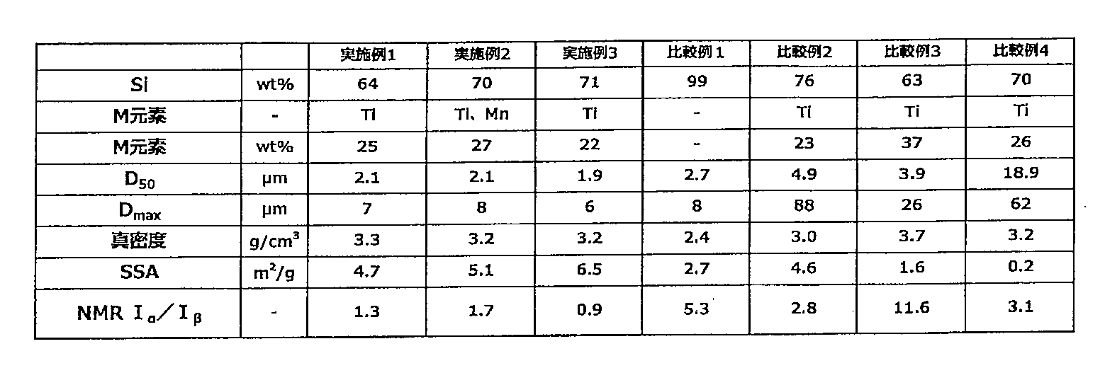
[規則26に基づく補充 03.06.2020]

[規則26に基づく補充 03.06.2020 ]

上記実施例及びこれまで発明者が行ってきた試験結果から、シリコンと、SiOa(0<a≦2)と、化学式MxSiy(ここで、x及びyは、0.1≦x/y≦7.0を満たし、Mは、Si以外の半金属元素及び金属元素のうちの1種又は2種以上である。)で表される化合物と、を含有する活物質に関しては、活物質中の上記M元素の含有量が5質量%より多く、38質量%未満であって、且つ、Single Pulse法により測定して得られる29Si-NMRスペクトルにおいて、シリコンに由来するピークの面積Iαと、SiOa(0<a≦2)に由来するピークの面積Iβの比(Iα/Iβ)が2.5以下であれば、これを電池、中でも固体電池、その中でも固体リチウム二次電池等の固体二次電池の負極活物質として用いることで、レート特性を高めることができ、且つサイクル特性を高めることができることが分かった。
Claims (8)
- シリコンと、SiOa(0<a≦2)と、化学式MxSiy(ここで、x及びyは、0.1≦x/y≦7.0を満たし、Mは、Si以外の半金属元素及び金属元素のうちの1種又は2種以上である。)で表される化合物と、を含有する活物質であり、
前記活物質中の前記Mの含有量は5質量%より多く、38質量%未満であり、
Single Pulse法により測定して得られる29Si-NMRスペクトルにおいて、シリコンに由来するピークの面積をIαとし、前記SiOa(0<a≦2)に由来するピークの面積をIβとしたとき、前記Iα及び前記Iβの比(Iα/Iβ)が2.5以下である活物質。 - 前記Mは、B、Ti、V、Mn、Fe、Co、Ni、Cu、Y、Zr、Nb、Mo、Ta及びWのうちの1種又は2種以上の元素である請求項1に記載の活物質。
- 真密度が2.4g/cm3より大きい請求項1又は請求項2に記載の活物質。
- 比表面積(SSA)が2.0m2/g以上である請求項1~3の何れかに記載の活物質。
- リチウム二次電池用の負極活物質として使用される請求項1~4の何れかに記載の活物質。
- 固体リチウム二次電池用の負極活物質として使用される請求項1~4の何れかに記載の活物質。
- 請求項1から請求項6までの何れかの請求項に記載の活物質を含有する負極。
- 正極と、負極と、前記正極および前記負極の間に設けられた固体電解質層とを有する固体電池であって、
前記負極が、請求項1から請求項6までの何れかの請求項に記載の活物質を含有する固体電池。
Priority Applications (1)
| Application Number | Priority Date | Filing Date | Title |
|---|---|---|---|
| JP2020572271A JPWO2020166601A1 (ja) | 2019-02-13 | 2020-02-12 |
Applications Claiming Priority (2)
| Application Number | Priority Date | Filing Date | Title |
|---|---|---|---|
| JP2019-023490 | 2019-02-13 | ||
| JP2019023490 | 2019-02-13 |
Publications (1)
| Publication Number | Publication Date |
|---|---|
| WO2020166601A1 true WO2020166601A1 (ja) | 2020-08-20 |
Family
ID=72044935
Family Applications (1)
| Application Number | Title | Priority Date | Filing Date |
|---|---|---|---|
| PCT/JP2020/005317 Ceased WO2020166601A1 (ja) | 2019-02-13 | 2020-02-12 | 活物質 |
Country Status (2)
| Country | Link |
|---|---|
| JP (1) | JPWO2020166601A1 (ja) |
| WO (1) | WO2020166601A1 (ja) |
Citations (5)
| Publication number | Priority date | Publication date | Assignee | Title |
|---|---|---|---|---|
| JP2007273182A (ja) * | 2006-03-30 | 2007-10-18 | Sony Corp | 集電体、負極及び電池 |
| JP2009164104A (ja) * | 2007-09-06 | 2009-07-23 | Canon Inc | 負極用電極材料、その製造方法ならびに該材料を用いた電極構造体及び蓄電デバイス |
| JP2010135336A (ja) * | 2003-03-26 | 2010-06-17 | Canon Inc | リチウム二次電池用の電極材料、該電極材料を有する電極構造体、及び該電極構造体を有する二次電池 |
| JP2013179033A (ja) * | 2012-02-01 | 2013-09-09 | Sanyo Special Steel Co Ltd | Si系合金負極材料 |
| JP2016225143A (ja) * | 2015-05-29 | 2016-12-28 | エルジー・ケム・リミテッド | 二次電池用負極材料及びそれを用いた非水電解質二次電池 |
-
2020
- 2020-02-12 JP JP2020572271A patent/JPWO2020166601A1/ja active Pending
- 2020-02-12 WO PCT/JP2020/005317 patent/WO2020166601A1/ja not_active Ceased
Patent Citations (5)
| Publication number | Priority date | Publication date | Assignee | Title |
|---|---|---|---|---|
| JP2010135336A (ja) * | 2003-03-26 | 2010-06-17 | Canon Inc | リチウム二次電池用の電極材料、該電極材料を有する電極構造体、及び該電極構造体を有する二次電池 |
| JP2007273182A (ja) * | 2006-03-30 | 2007-10-18 | Sony Corp | 集電体、負極及び電池 |
| JP2009164104A (ja) * | 2007-09-06 | 2009-07-23 | Canon Inc | 負極用電極材料、その製造方法ならびに該材料を用いた電極構造体及び蓄電デバイス |
| JP2013179033A (ja) * | 2012-02-01 | 2013-09-09 | Sanyo Special Steel Co Ltd | Si系合金負極材料 |
| JP2016225143A (ja) * | 2015-05-29 | 2016-12-28 | エルジー・ケム・リミテッド | 二次電池用負極材料及びそれを用いた非水電解質二次電池 |
Also Published As
| Publication number | Publication date |
|---|---|
| JPWO2020166601A1 (ja) | 2020-08-20 |
Similar Documents
| Publication | Publication Date | Title |
|---|---|---|
| JP4865556B2 (ja) | リチウムイオン電池用の多相ケイ素含有電極 | |
| KR101884476B1 (ko) | 리튬 이온 전지용 부극재 | |
| US9478800B2 (en) | Negative electrode active material for nonaqueous electrolyte secondary batteries | |
| JP6978563B2 (ja) | Si系負極活物質 | |
| KR101711525B1 (ko) | 정극 활물질 | |
| JP5367921B2 (ja) | 非水電解液二次電池用負極活物質 | |
| TWI635645B (zh) | Si-based eutectic alloy for negative electrode active material of power storage device and method for producing same | |
| US10483531B2 (en) | Negative electrode active material for nonaqueous electrolyte secondary batteries | |
| KR100589368B1 (ko) | 리튬 이차 전지용 전극 재료, 리튬 이차 전지, 및 리튬이차 전지용 전극 재료의 제조 방법 | |
| WO2019017349A1 (ja) | 負極活物質材料、負極及び電池 | |
| JP3624417B2 (ja) | 負極活物質及びその製造方法、並びに非水電解質電池 | |
| WO2020166658A1 (ja) | 活物質 | |
| US20220131137A1 (en) | Active Material | |
| WO2020166601A1 (ja) | 活物質 | |
| WO2015163398A1 (ja) | 非水電解液二次電池用負極活物質 | |
| WO2020166599A1 (ja) | 活物質 | |
| KR101505257B1 (ko) | 비수 전해질 2차 전지의 음극 재료 및 그 제조 방법 | |
| US8591765B2 (en) | Negative electrode material for nonaqueous electrolyte secondary batteries and manufacturing method thereof | |
| WO2022202357A1 (ja) | 活物質及びその製造方法 | |
| WO2022202356A1 (ja) | Liイオン二次電池用正極活物質及びその製造方法、並びにLiイオン二次電池用正極及びLiイオン二次電池 |
Legal Events
| Date | Code | Title | Description |
|---|---|---|---|
| 121 | Ep: the epo has been informed by wipo that ep was designated in this application |
Ref document number: 20756521 Country of ref document: EP Kind code of ref document: A1 |
|
| ENP | Entry into the national phase |
Ref document number: 2020572271 Country of ref document: JP Kind code of ref document: A |
|
| NENP | Non-entry into the national phase |
Ref country code: DE |
|
| 122 | Ep: pct application non-entry in european phase |
Ref document number: 20756521 Country of ref document: EP Kind code of ref document: A1 |