WO2020166254A1 - 電力変換装置 - Google Patents
電力変換装置 Download PDFInfo
- Publication number
- WO2020166254A1 WO2020166254A1 PCT/JP2020/000948 JP2020000948W WO2020166254A1 WO 2020166254 A1 WO2020166254 A1 WO 2020166254A1 JP 2020000948 W JP2020000948 W JP 2020000948W WO 2020166254 A1 WO2020166254 A1 WO 2020166254A1
- Authority
- WO
- WIPO (PCT)
- Prior art keywords
- power
- diagnostic
- switching element
- shield
- power supply
- Prior art date
- Legal status (The legal status is an assumption and is not a legal conclusion. Google has not performed a legal analysis and makes no representation as to the accuracy of the status listed.)
- Ceased
Links
Images

Classifications
-
- G—PHYSICS
- G01—MEASURING; TESTING
- G01R—MEASURING ELECTRIC VARIABLES; MEASURING MAGNETIC VARIABLES
- G01R31/00—Arrangements for testing electric properties; Arrangements for locating electric faults; Arrangements for electrical testing characterised by what is being tested not provided for elsewhere
- G01R31/50—Testing of electric apparatus, lines, cables or components for short-circuits, continuity, leakage current or incorrect line connections
-
- H—ELECTRICITY
- H02—GENERATION; CONVERSION OR DISTRIBUTION OF ELECTRIC POWER
- H02M—APPARATUS FOR CONVERSION BETWEEN AC AND AC, BETWEEN AC AND DC, OR BETWEEN DC AND DC, AND FOR USE WITH MAINS OR SIMILAR POWER SUPPLY SYSTEMS; CONVERSION OF DC OR AC INPUT POWER INTO SURGE OUTPUT POWER; CONTROL OR REGULATION THEREOF
- H02M7/00—Conversion of AC power input into DC power output; Conversion of DC power input into AC power output
- H02M7/42—Conversion of DC power input into AC power output without possibility of reversal
- H02M7/44—Conversion of DC power input into AC power output without possibility of reversal by static converters
- H02M7/48—Conversion of DC power input into AC power output without possibility of reversal by static converters using discharge tubes with control electrode or semiconductor devices with control electrode
Definitions
- the present invention relates to a power conversion device.
- Patent Document 1 discloses that a DC voltage generating means, an inverter device, a load of the inverter device, a shield wire electrically connecting the DC voltage generating means, the inverter device, and the load, and one end of an output.
- an electrical connection diagnosis method comprising a grounded power supply, wherein the shield part of the shielded wire is grounded at a location other than the inverter device, and the connection of the shielded wire is diagnosed by energizing the shield part from the power supply. Has been done.
- the shield wire is grounded via a capacitor on the inverter device side, while the shield wire is grounded directly on the load side without a capacitor. Therefore, if electric charges are accumulated in the capacitor on the side of the inverter device, the voltage between the inverter device and the load may not be maintained at the same potential, and a voltage may be applied to the shield wire. In this case, there is a risk of electric shock if a person touches it while the shield wire is broken.
- the present invention aims to safely diagnose the connection state of the AC wiring connected between the inverter and the load.
- the power converter according to the present invention converts DC power supplied from a high-voltage power supply into AC power, and outputs the AC power to a load through an AC wiring formed by surrounding a core wire with a shield wire.
- the one end side of the shield wire is electrically connected to the frame ground of the load, and the power conversion device establishes a conduction state between the other end side of the shield wire and the diagnostic power supply.
- the conduction state of the shield wire when the diagnosis power source is electrically connected and the second switching element disconnects the other end side of the shield wire from the frame ground of the power conversion device.
- a control circuit for diagnosing the state of the AC wiring based on the above.
- connection state of the AC wiring connected between the inverter and the load can be safely diagnosed.
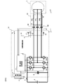
- FIG. 1 is a configuration diagram of a motor drive system according to a first embodiment of the present invention.
- the motor drive system shown in FIG. 1 is used by being mounted in a vehicle such as an automobile, and is configured by connecting an inverter 1 and a motor 2 via an AC wiring 3.
- the inverter 1 corresponds to the power converter according to the embodiment of the present invention, and includes a power supply circuit 11, a power conversion control circuit 12, a diagnostic control circuit 13, a smoothing capacitor 14, and power conversion switching elements 15U, 15V, 15W, 16U. , 16V and 16W, switching elements 17U, 17V and 17W for diagnosis, switching elements 18U, 18V and 18W for grounding, and current detectors 19U, 19V and 19W.
- the power supply circuit 11 is connected to the low voltage battery 4, and uses the DC power supplied from the low voltage battery 4 to generate a plurality of types of power supplies used in the inverter 1.
- the power source generated by the power source circuit 11 includes the operating power source of the power conversion control circuit 12 and the diagnostic control circuit 13, and the diagnostic power source 10 connected to the AC wiring 3 via the diagnostic switching elements 17U to 17W. Be done.
- the diagnostic power supply 10 is used when the diagnostic control circuit 13 diagnoses the AC wiring 3, and the connection state with the AC wiring 3 is switched according to the switching operation of the diagnostic switching elements 17U to 17W.
- the power supply circuit 11 has a current limiting function for short-circuit protection and that the power supply circuit 11 perform a predetermined safety operation when any of the power supplies is short-circuited.
- the power conversion control circuit 12 operates by receiving power supply from the power supply circuit 11, and controls the switching states of the power conversion switching elements 15U to 16W to perform power conversion from DC power to AC power. Generate a signal.
- the power conversion control circuit 12 determines timings for turning on and off the power conversion switching elements 15U to 16W, respectively, by PWM control based on a torque request value input from a higher-order controller (not shown), and drives signals according to the timings. To generate.
- the drive signal generated by the power conversion control circuit 12 is output to each of the power conversion switching elements 15U to 16W.
- the diagnostic control circuit 13 operates by receiving power supply from the power supply circuit 11 and generates switching signals for controlling switching states of the diagnostic switching elements 17U to 17W and the ground switching elements 18U to 18W, respectively.
- the state of the AC wiring 3 is diagnosed.
- the switching signal generated by the diagnostic control circuit 13 is output to the diagnostic switching elements 17U to 17W and the ground switching elements 18U to 18W, respectively.
- the diagnostic control circuit 13 is configured using, for example, a microcomputer that executes a predetermined program, an FPGA, or the like. The method of generating the switching signal by the diagnostic control circuit 13 and the method of diagnosing the AC wiring 3 will be described in detail later.
- the power conversion switching elements 15U to 16W perform a switching operation in accordance with a drive signal input from the power conversion control circuit 12 to convert the DC power supplied from the high-voltage battery 5 into three-phase AC power. It outputs to the motor 2 which is a load through the AC wiring 3.
- the power conversion switching elements 15U and 16U are for the U phase of the three-phase AC power
- the power conversion switching elements 15V and 16V are for the V phase of the three-phase AC power
- the power conversion switching elements 15W and 16W are for the three-phase AC power. Each corresponds to the W phase.
- IGBT or MOSFET can be used for the power conversion switching elements 15U to 16W.
- the high-voltage battery 5 is connected to the power conversion switching elements 15U to 16W via the contactor 6.
- the contactor 6 When the contactor 6 is turned on by a host controller (not shown), the supply of DC power from the high voltage battery 5 is started.
- a smoothing capacitor 14 is connected to the high-voltage battery 5 in parallel with the power conversion switching elements 15U to 16W, and the DC power from the high-voltage battery 5 is smoothed by the smoothing capacitor 14.
- the AC wiring 3 is composed of cables 31U, 31V, 31W corresponding to the U phase, V phase, and W phase, respectively.
- the U-phase cable 31U is connected to the power conversion switching elements 15U and 16U, and transmits the U-phase AC power generated by being converted from the DC power by the switching operation from the inverter 1 to the motor 2.
- the V-phase cable 31V is connected to the power conversion switching elements 15V and 16V, and transmits V-phase AC power generated by being converted from DC power by the switching operation of the inverter 1 to the motor 2.
- the W-phase cable 31W is connected to the power conversion switching elements 15W and 16W, and transmits W-phase AC power generated by being converted from DC power by the switching operation of these to the motor 2.
- the cable 31U has a core wire 32U connected between the power conversion switching elements 15U and 16U and a U-phase winding (not shown) of the motor 2, and a shield wire 33U surrounding the core wire 32U.
- One end side of the shield wire 33U, that is, the motor 2 side is electrically connected to the frame ground 8 of the motor 2.
- the other end side of the shield wire 33U, that is, the inverter 1 side is connected to the diagnostic power source 10 via the diagnostic switching element 17U and the current detector 19U, and is also connected to the frame ground of the inverter 1 via the ground switching element 18U. 7 is electrically connected.
- the cable 31V has a core wire 32V connected between the power conversion switching elements 15V and 16V and a V-phase winding (not shown) of the motor 2, and a shield wire 33V surrounding the core wire 32V.
- One end side of the shield wire 33V, that is, the motor 2 side is electrically connected to the frame ground 8 of the motor 2.
- the other end of the shielded wire 33V, that is, the inverter 1 side is connected to the diagnostic power source 10 via the diagnostic switching element 17V and the current detector 19V, and is connected to the frame ground of the inverter 1 via the ground switching element 18V. 7 is electrically connected.
- the cable 31W has a core wire 32W connected between the power conversion switching elements 15W and 16W and a W-phase winding (not shown) included in the motor 2, and a shield wire 33W surrounding the core wire 32W.
- One end side of the shield wire 33W, that is, the motor 2 side is electrically connected to the frame ground 8 of the motor 2.
- the other end side of the shield wire 33W, that is, the inverter 1 side is connected to the diagnostic power source 10 via the diagnostic switching element 17W and the current detector 19W, and is also connected to the frame ground of the inverter 1 via the ground switching element 18W. 7 is electrically connected.
- the frame ground 7 of the inverter 1 and the frame ground 8 of the motor 2 are preferably electrically connected to each other.
- these can be electrically connected to each other by connecting them to the body of the vehicle.
- the switching element 17U for diagnosis, the switching element 18U for grounding, and the current detector 19U are provided corresponding to the shield wire 33U.
- the diagnostic switching element 17U switches the conduction state between the other end of the shielded wire 33U and the diagnostic power source 10 in response to a switching signal input from the diagnostic control circuit 13.
- the grounding switching element 18U switches the conduction state between the other end of the shielded wire 33U and the frame ground 7 of the inverter 1 according to the switching signal input from the diagnostic control circuit 13.
- the current detector 19U detects a current flowing through the shield wire 33U via the diagnostic switching element 17U when the shield wire 33U and the diagnostic power supply 10 are in a conductive state, and outputs the detection result to the diagnostic control circuit 13.
- the diagnostic control circuit 13 diagnoses the state of the U-phase cable 31U based on the current detection result by the current detector 19U.
- the switching element for diagnosis 17V, the switching element for grounding 18V, and the current detector 19V are provided corresponding to the shield wire 33V.
- the diagnostic switching element 17V switches the conduction state between the other end of the shielded wire 33V and the diagnostic power supply 10 in response to a switching signal input from the diagnostic control circuit 13.
- the grounding switching element 18V switches the conduction state between the other end of the shielded wire 33V and the frame ground 7 of the inverter 1 according to the switching signal input from the diagnostic control circuit 13.
- the current detector 19V detects a current flowing through the shield line 33V via the diagnostic switching element 17V when the shield line 33V and the diagnostic power supply 10 are in a conductive state, and outputs the detection result to the diagnostic control circuit 13.
- the diagnosis control circuit 13 diagnoses the state of the V-phase cable 31V based on the current detection result by the current detector 19V.
- the diagnostic switching element 17W, the ground switching element 18W, and the current detector 19W are provided corresponding to the shield wire 33W.
- the diagnostic switching element 17W switches the conduction state between the other end side of the shielded wire 33W and the diagnostic power source 10 according to the switching signal input from the diagnostic control circuit 13.
- the grounding switching element 18W switches the conduction state between the other end of the shielded wire 33W and the frame ground 7 of the inverter 1 according to the switching signal input from the diagnostic control circuit 13.
- the current detector 19W detects a current flowing through the shield line 33W via the diagnostic switching element 17W when the shield line 33W and the diagnostic power supply 10 are in a conductive state, and outputs the detection result to the diagnostic control circuit 13.
- the diagnosis control circuit 13 diagnoses the state of the W-phase cable 31W based on the current detection result by the current detector 19W.
- the motor 2 acts as a load of the inverter 1 by receiving AC power transmitted from the inverter 1 through the AC wiring 3 and rotatingly driving a rotor (not shown).
- the rotational drive of the motor 2 is used as a driving force for driving the vehicle, for example.
- Current sensors 9U, 9V, 9W are arranged between the inverter 1 and the motor 2.
- the current sensor 9U detects the U-phase AC current flowing through the cable 31U and outputs the detection result to the power conversion control circuit 12.
- the current sensor 9V detects the V-phase AC current flowing through the cable 31V and outputs the detection result to the power conversion control circuit 12.
- the current sensor 9W detects the W-phase AC current flowing through the cable 31W and outputs the detection result to the power conversion control circuit 12.
- the power conversion control circuit 12 uses these detection results to generate drive signals to be output to the power conversion switching elements 15U to 16W.
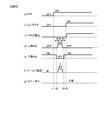
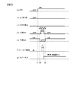
- FIGS. 2 and 3 are diagrams showing an example of a timing chart of each signal related to the diagnosis of the AC wiring 3.
- FIG. 2 shows an example in which the AC wiring 3 is in a normal state
- FIG. 3 shows an example in which the AC wiring 3 is in an abnormal state.
- (a) shows an ignition signal of the vehicle
- (b) shows an on/off state of the contactor 6, and (c) shows DC power supplied from the high-voltage battery 5 to the inverter 1. It shows the voltage.
- (D) shows the on/off state of the upper switches to which the shield wires 33U to 33W are connected in the inverter 1, that is, the diagnostic switching elements 17U to 17W
- (e) shows the shield wires 33U to 33W in the inverter 1.
- the ON/OFF states of the connected lower switches, that is, the ground switching elements 18U to 18W are shown.
- (F) shows a shield current flowing through each of the shield wires 33U to 33W
- (g) shows a status signal output from the diagnosis control circuit 13 as a diagnosis result of the AC wiring 3.
- the power of the inverter 1 is turned on accordingly and the power supply circuit 11 performs the diagnosis.
- Generation of the power supply 10 for use is started.
- the diagnostic switching elements 17U to 17W are in the off state, and the shield lines 33U to 33W and the diagnostic power source 10 are disconnected.
- the ground switching elements 18U to 18W are in the ON state, and the shield lines 33U to 33W and the frame ground 7 of the inverter 1 are electrically connected.
- the diagnostic control circuit 13 switches the ground switching elements 18U to 18W from on to off at time t2, thereby shielding the shield wire 33U. ⁇ 33 W is cut off from the frame ground 7 of the inverter 1. Then, as shown in (d), the switching elements 17U to 17W for diagnosis are switched from off to on, so that the shield wires 33U to 33W and the diagnostic power supply 10 are electrically connected. At this time, the diagnostic control circuit 13 sets a predetermined dead time period td for turning off the ground switching elements 18U to 18W and turning on the diagnostic switching elements 17U to 17W together. It is provided to generate and output switching signals for the diagnostic switching elements 17U to 17W and the ground switching elements 18U to 18W.
- the diagnostic control circuit 13 sets a predetermined diagnostic determination period tj as shown in (f) corresponding to the timing when the diagnostic switching elements 17U to 17W are turned on. Then, the AC wiring 3 is diagnosed by comparing the shield current detected in the diagnosis determination period tj with a predetermined determination threshold th. In the case of FIG. 2, since the shield current in the diagnosis determination period tj is equal to or greater than the determination threshold th, the diagnostic control circuit 13 diagnoses that the AC wiring 3 is normal. In this case, the diagnostic control circuit 13 outputs the status signal to the host controller (not shown) without changing the L level as shown in FIG.
- the diagnostic control circuit 13 switches the diagnostic switching elements 17U to 17W from ON to OFF as shown in (d) when a predetermined ON period tn elapses after the diagnostic switching elements 17U to 17W are turned ON. Then, the shield lines 33U to 33W and the diagnostic power source 10 are disconnected again. After that, at a time t3 when a predetermined dead time period td has elapsed, the ground switching elements 18U to 18W are switched from OFF to ON as shown in (e), so that the shield wires 33U to 33W and the frame ground 7 of the inverter 1 are switched. Conducts again between and.
- the host controller Upon receiving the above status signal from the diagnostic control circuit 13, the host controller determines that the diagnostic result of the AC wiring 3 is normal, and switches the contactor 6 from off to on at time t4 as shown in FIG. 2(b). .. As a result, as shown in (c), the voltage of the DC power supplied from the high-voltage battery 5 to the inverter 1 rises, and the inverter 1 starts the power conversion operation from the DC power to the AC power.
- the AC wiring 3 is in an abnormal state
- the ignition signal changes from off to on at time t1 as shown in FIG. 3A
- the power of the inverter 1 is turned on accordingly and the power supply circuit 11
- the generation of the diagnostic power supply 10 is started.
- the switching states of the diagnostic switching elements 17U to 17W and the ground switching elements 18U to 18W at this time are the same as those in FIG. That is, as shown in (d), the diagnostic switching elements 17U to 17W are in the off state, and the shield lines 33U to 33W and the diagnostic power source 10 are disconnected.
- the ground switching elements 18U to 18W are in the ON state, and the shield lines 33U to 33W and the frame ground 7 of the inverter 1 are electrically connected.
- the diagnostic control circuit 13 switches the diagnostic switching elements 17U to 17W and the ground switching elements 18U to 18W at the same timing as in FIG. That is, the ground switching elements 18U to 18W are switched from on to off at time t2, and the diagnostic switching elements 17U to 17W are switched from off to on after the lapse of a predetermined dead time period td. Then, the current detectors 19U to 19W are used to detect the shield currents flowing through the shield wires 33U to 33W, respectively.
- the diagnostic switching elements 17U to 17W are switched from ON to OFF, so that the shield wires 33U to 33W and the diagnostic power source 10 are connected. Shut off again.
- the ground switching elements 18U to 18W are switched from off to on, so that the shield lines 33U to 33W and the frame ground 7 of the inverter 1 are electrically connected again. ..
- the connectors attached to the U-phase, V-phase, and W-phase cables 31U, 31V, 31W are The case corresponds to the case where it is disconnected from the inverter 1 or the motor 2, or the case where the shield wires 33U to 33W of each cable come out from the connector while the connector is fixed to the inverter 1 or the motor 2.
- each cable is completely broken, that is, when both the core wires 32U to 32W and the shield wires 33U to 33W are broken.
- the diagnostic switching elements 17U to 17W connect the shield wires 33U to 33W and the diagnostic power source 10 as shown in FIG. 3(f). No shield current flows through.
- the diagnostic control circuit 13 compares the shield current detected in the preset predetermined diagnostic determination period tj with a predetermined determination threshold th, as described in FIG. 2, to diagnose the AC wiring 3. To do. In the case of FIG. 3, since the shield current in the diagnosis determination period tj is less than the determination threshold th as shown in (f), the diagnostic control circuit 13 diagnoses that the AC wiring 3 is abnormal. In this case, the diagnostic control circuit 13 changes the status signal from the L level to the H level as shown in (g), and outputs the status signal to a host controller (not shown).
- the host controller determines that the diagnostic result of the AC wiring 3 is abnormal and keeps the contactor 6 off as shown in FIG. 3(b).
- the host controller determines that the diagnostic result of the AC wiring 3 is abnormal and keeps the contactor 6 off as shown in FIG. 3(b).
- the diagnostic switching elements 17U to 17W disconnect the shield wires 33U to 33W from the diagnostic power source 10, and the ground switching element 18U to The shield wires 33U to 33W are electrically connected to the frame ground 7 of the inverter 1 by 18W. Therefore, the voltage of the shield wires 33U to 33W with respect to the frame ground 7 of the inverter 1 and the frame ground 8 of the motor 2 can be set to 0, and even if a person touches the shield wires 33U to 33W in a disconnected state, an electric shock may occur. The danger can be avoided.
- the diagnostic switching elements 17U to 17W When the AC wiring 3 is diagnosed as described above, by turning on the diagnostic switching elements 17U to 17W, a shield current flows through the shield wires 33U to 33W via the diagnostic switching elements 17U to 17W. Therefore, in order to prevent an excessive shield current from flowing, the diagnostic switching elements 17U to 17W need to have a certain resistance value in the ON state.
- the ground switching elements 18U to 18W are turned on so that the shield wires 33U to 33W are electrically connected to the frame ground 7 of the inverter 1 via the ground switching elements 18U to 18W. Connected to.
- the grounding switching elements 18U to 18W have a resistance value as small as possible in the ON state, and at least the resistance value in the ON state is smaller than that of the diagnostic switching elements 17U to 17W. Is preferred.
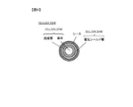
- FIG. 4 is a sectional view showing a structural example of the AC wiring 3 according to the first embodiment of the present invention.
- the cables 31U, 31V, 31W forming the AC wiring 3 each have a structure as shown in FIG. That is, the central portion where the conductor is covered with the insulating layer corresponds to the core wires 32U, 32V, 32W, and this is surrounded by the electric shield layer corresponding to the shield wires 33U, 33V, 33W. The outside of the electric shield layer is covered with a sheath for protecting and insulating each cable.
- the inverter 1 converts DC power supplied from the high-voltage battery 5 into AC power, and AC power is supplied via the AC wiring 3 formed by surrounding the core wires 32U to 32W with the shield wires 33U to 33W. Is output to the motor 2, which is a load. One ends of the shield wires 33U to 33W are electrically connected to the frame ground 8 of the motor 2.
- the inverter 1 includes a diagnostic switching element 17U to 17W that switches a conduction state between the other end side of the shielded wires 33U to 33W and the diagnostic power supply 10, and the other end side of the shielded wires 33U to 33W and the frame ground of the inverter 1.
- the grounding switching elements 18U to 18W for switching the conduction state between the diagnostic control circuit 13 and the control circuit 7 are provided.
- the diagnostic control circuit 13 connects the other ends of the shield wires 33U to 33W to the diagnostic power source 10 by the diagnostic switching elements 17U to 17W, and shields the shield wires 33U to 33W by the ground switching elements 18U to 18W.
- the state of the AC wiring 3 is diagnosed based on the energized state of the shielded wires 33U to 33W when the other end side and the frame ground 7 of the inverter 1 are cut off.
- the voltage of the shield wires 33U to 33W with respect to the frame ground 7 of the inverter 1 and the frame ground 8 of the motor 2 can be set to 0 except when diagnosing the AC wiring 3, so that the shield wires 33U to 33W are disconnected. Even if a person touches it while operating, the risk of electric shock can be avoided. Therefore, the connection state of the AC wiring 3 connected between the inverter 1 and the motor 2 can be safely diagnosed.
- the AC wiring 3 includes a plurality of core wires 32U to 32W for transmitting U-phase, V-phase, and W-phase AC power, and a plurality of shield wires 33U to 33W surrounding the core wires 32U to 32W.
- the diagnostic switching elements 17U to 17W and the ground switching elements 18U to 18W are provided respectively for the shield lines 33U to 33W. Since it did in this way, the connection state can be safely diagnosed about each of the cables 31U, 31V, and 31W which comprise the alternating current wiring 3.
- the diagnostic control circuit 13 provides a dead time period td in which both the diagnostic switching elements 17U to 17W and the ground switching elements 18U to 18W are turned off, and the diagnostic switching elements 17U to 17W and the ground switching element are provided. Switching control from 18U to 18W is performed. Since it did in this way, it can prevent that the diagnostic power supply 10 and the frame ground 7 are short-circuited in the inverter 1, and can improve safety.
- the inverter 1 further includes a power supply circuit 11 that generates the diagnostic power supply 10. As described with reference to FIGS. 2 and 3, the diagnostic control circuit 13 operates from the time when the power supply circuit 11 starts generating the diagnostic power supply 10 to the time when the high-voltage battery 5 starts supplying DC power, that is, the time.
- the other ends of the shield wires 33U to 33W and the diagnostic power supply 10 are electrically connected (the diagnostic switching elements 17U to 17W are turned on), and the shield wires 33U to 33W are Switching control of the diagnostic switching elements 17U to 17W and the ground switching elements 18U to 18W is performed so that the end side is disconnected from the frame ground 7 of the inverter 1 (the ground switching elements 18U to 18W are turned off). Then, the AC wiring 3 is diagnosed. Since it did in this way, when the connection state of the alternating current wiring 3 is abnormal, the supply of direct-current power from the high voltage battery 5 to the inverter 1 can be prevented in advance. Therefore, the inverter 1 and the motor 2 can be kept in a safe state where high voltage is not applied.
- the diagnostic control circuit 13 shields the power supply circuit 11 before time t1 when the power supply circuit 11 starts generating the diagnostic power supply 10 and after time t4 when the high-voltage battery 5 starts supplying DC power.
- the other ends of the lines 33U to 33W and the diagnostic power supply 10 are disconnected (the diagnostic switching elements 17U to 17W are turned off), and the other ends of the shield lines 33U to 33W and the frame ground 7 of the inverter 1 are connected to each other.
- the switching control of the diagnostic switching elements 17U to 17W and the ground switching elements 18U to 18W is performed so that the electrical connection is established between them (the ground switching elements 18U to 18W are turned on).
- the voltage of the shield wires 33U to 33W with respect to the frame ground 7 of the inverter 1 and the frame ground 8 of the motor 2 is surely set to 0 except when diagnosing the AC wiring 3, and the risk of electric shock is avoided. be able to.
- the grounding switching elements 18U to 18W have a smaller resistance value in the ON state than the diagnostic switching elements 17U to 17W. By doing so, it is possible to prevent an excessive shield current from flowing through the shield wires 33U to 33W when diagnosing the AC wiring 3, and reduce the ground resistance of the shield wires 33U to 33W.
- FIG. 5 is a configuration diagram of a motor drive system according to the second embodiment of the present invention.
- the motor drive system shown in FIG. 5 is used by being mounted in a vehicle such as an automobile, for example, similarly to the motor drive system of FIG. 1 described in the first embodiment, and the inverter 1A and the motor 2 are AC. It is configured by being connected via the wiring 3A.
- the AC wiring 3A has core wires 32U, 32V, 32W respectively corresponding to the U phase, the V phase, and the W phase, which are gathered in one cable 31.
- the difference is that one shield wire 33 is provided on the cable 31.
- the inverter 1A is different from the inverter 1 described in the first embodiment in that the diagnostic switching elements 17U to 17W, the ground switching elements 18U to 18W, and the current detectors 19U to 19W in FIG. The difference is that one diagnostic switching element 17, one ground switching element 18, and one current detector 19 are provided for each shield line 33.
- the diagnostic control circuit 13 performs switching control of the diagnostic switching element 17 and the grounding switching element 18 at a predetermined timing and uses the current detector 19 by the same procedure as described in the first embodiment.
- the shield current flowing through the shield wire 33 is detected.
- a host controller not shown.
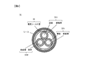
- FIG. 6 is a cross-sectional view showing a structural example of the AC wiring 3A according to the second embodiment of the present invention.
- the cable 31 forming the AC wiring 3A has a structure as shown in FIG. That is, one electric shield layer corresponding to the shield wire 33 collectively surrounds the three core wires 32U, 32V, 32W formed by covering the conductor with the insulating layer. The outside of this electric shield layer is covered with a sheath for protecting and insulating the cable 31.
- the AC wiring 3 includes the plurality of core wires 32U to 32W and the core wires 32U to 32W that respectively transmit the U-phase, V-phase, and W-phase AC power. And one shield wire 33 that collectively surrounds.
- the diagnostic switching element 17 and the ground switching element 18 are provided for each shield line 33. Since this is done, it is possible to safely diagnose the connection state of the AC wiring 3 while reducing the number of diagnostic switching elements and ground switching elements.
Landscapes
- Engineering & Computer Science (AREA)
- Power Engineering (AREA)
- Physics & Mathematics (AREA)
- General Physics & Mathematics (AREA)
- Inverter Devices (AREA)
Abstract
インバータと負荷の間に接続される交流配線の接続状態を安全に診断することを目的とする。 インバータ(1)は、高電圧バッテリ(5)から供給される直流電力を交流電力に変換し、交流配線(3)を介して交流電力を負荷であるモータ(2)に出力する。交流配線(3)のシールド線(33U~33W)の一端側は、モータ(2)のフレームグランド(8)と電気的に接続されている。診断制御回路(13)は、診断用スイッチング素子(17U~17W)によりシールド線(33U~33W)の他端側と診断用電源(10)との間が導通され、かつ、接地用スイッチング素子(18U~18W)によりシールド線(33U~33W)の他端側とインバータ(1)のフレームグランド(7)との間が遮断されているときのシールド線(33U~33W)の通電状態に基づいて、交流配線(3)の状態を診断する。
Description
本発明は、電力変換装置に関する。
本技術分野の背景技術として、下記特許文献1が知られている。特許文献1には、直流電圧発生手段と、インバータ装置と、前記インバータ装置の負荷と、前記直流電圧発生手段、前記インバータ装置、前記負荷との間を電気接続するシールド線と、出力の一端が接地された電源とを備え、前記シールド線のシールド部は、前記インバータ装置以外の箇所では接地されて、前記電源より前記シールド部へ通電し前記シールド線の接続を診断する電気接続診断方法が開示されている。
特許文献1の技術では、インバータ装置側ではシールド線がコンデンサを介して接地されている一方で、負荷側ではシールド線がコンデンサを介さずに直接接地されている。そのため、インバータ装置側でコンデンサに電荷が溜まると、インバータ装置と負荷の間を等電位に保てず、シールド線に電圧が印加された状態となる場合がある。この場合、シールド線が断線している状態で人が触れると感電の危険性がある。
本発明は、上記課題を解決するため、インバータと負荷の間に接続される交流配線の接続状態を安全に診断することを目的とする。
本発明による電力変換装置は、高電圧電源から供給される直流電力を交流電力に変換し、心線がシールド線で囲われて形成された交流配線を介して前記交流電力を負荷に出力するものであって、前記シールド線の一端側は、前記負荷のフレームグランドと電気的に接続されており、前記電力変換装置は、前記シールド線の他端側と診断用電源との間の導通状態を切り替える第1スイッチング素子と、前記シールド線の他端側と前記電力変換装置のフレームグランドとの間の導通状態を切り替える第2スイッチング素子と、前記第1スイッチング素子により前記シールド線の他端側と前記診断用電源との間が導通され、かつ、前記第2スイッチング素子により前記シールド線の他端側と前記電力変換装置のフレームグランドとの間が遮断されているときの前記シールド線の通電状態に基づいて、前記交流配線の状態を診断する制御回路と、を備える。
本発明によれば、インバータと負荷の間に接続される交流配線の接続状態を安全に診断することができる。
(第1の実施形態)
図1は、本発明の第1の実施形態に係るモータ駆動システムの構成図である。図1に示すモータ駆動システムは、例えば自動車等の車両に搭載されて使用されるものであり、インバータ1とモータ2が交流配線3を介して接続されることにより構成されている。
図1は、本発明の第1の実施形態に係るモータ駆動システムの構成図である。図1に示すモータ駆動システムは、例えば自動車等の車両に搭載されて使用されるものであり、インバータ1とモータ2が交流配線3を介して接続されることにより構成されている。
インバータ1は、本発明の一実施形態に係る電力変換装置に相当し、電源回路11、電力変換制御回路12、診断制御回路13、平滑コンデンサ14、電力変換用スイッチング素子15U,15V,15W,16U,16Vおよび16W、診断用スイッチング素子17U,17Vおよび17W、接地用スイッチング素子18U,18Vおよび18W、電流検出器19U,19Vおよび19Wを有している。
電源回路11は、低電圧バッテリ4と接続されており、低電圧バッテリ4から供給される直流電力を用いて、インバータ1において使用される複数種類の電源を生成する。この電源回路11により生成される電源には、電力変換制御回路12や診断制御回路13の動作電源とともに、診断用スイッチング素子17U~17Wを介して交流配線3と接続される診断用電源10が含まれる。この診断用電源10は、診断制御回路13が交流配線3の診断を行う際に利用される電源であり、診断用スイッチング素子17U~17Wの切り替え動作に応じて交流配線3との接続状態が切り替えられる。なお、短絡保護のため、電源回路11に電流制限機能を持たせるとともに、いずれかの電源が短絡したときには所定の安全動作を電源回路11に実行させることが好ましい。
電力変換制御回路12は、電源回路11からの電源供給を受けて動作し、電力変換用スイッチング素子15U~16Wのスイッチング状態をそれぞれ制御して直流電力から交流電力への電力変換を行うための駆動信号を生成する。電力変換制御回路12は、例えば不図示の上位コントローラから入力されるトルク要求値に基づくPWM制御により、電力変換用スイッチング素子15U~16Wをそれぞれオンおよびオフさせるタイミングを決定し、そのタイミングに従って駆動信号を生成する。電力変換制御回路12により生成された駆動信号は、電力変換用スイッチング素子15U~16Wにそれぞれ出力される。
診断制御回路13は、電源回路11からの電源供給を受けて動作し、診断用スイッチング素子17U~17Wおよび接地用スイッチング素子18U~18Wの切り替え状態をそれぞれ制御するための切替信号を生成するとともに、交流配線3の状態を診断する。診断制御回路13により生成された切替信号は、診断用スイッチング素子17U~17Wおよび接地用スイッチング素子18U~18Wにそれぞれ出力される。診断制御回路13は、例えば所定のプログラムを実行するマイクロコンピュータや、FPGA等を用いて構成される。なお、診断制御回路13による切替信号の生成方法および交流配線3の診断方法については、後で詳細に説明する。
電力変換用スイッチング素子15U~16Wは、電力変換制御回路12から入力される駆動信号に応じてスイッチング動作を行うことにより、高電圧バッテリ5から供給される直流電力を三相交流電力に変換し、交流配線3を介して負荷であるモータ2に出力する。電力変換用スイッチング素子15Uおよび16Uは三相交流電力のU相に、電力変換用スイッチング素子15Vおよび16Vは三相交流電力のV相に、電力変換用スイッチング素子15Wおよび16Wは三相交流電力のW相に、それぞれ対応している。なお、電力変換用スイッチング素子15U~16Wには、例えばIGBTやMOSFETを用いることができる。
高電圧バッテリ5は、コンタクタ6を介して電力変換用スイッチング素子15U~16Wと接続されている。不図示の上位コントローラによってコンタクタ6がオンされることで、高電圧バッテリ5からの直流電力の供給が開始される。高電圧バッテリ5には電力変換用スイッチング素子15U~16Wと並列に平滑コンデンサ14が接続されており、この平滑コンデンサ14によって高電圧バッテリ5からの直流電力が平滑化される。
交流配線3は、U相、V相、W相にそれぞれ対応するケーブル31U,31V,31Wによって構成される。U相のケーブル31Uは、電力変換用スイッチング素子15Uおよび16Uと接続されており、これらのスイッチング動作によって直流電力から変換されて生成されたU相交流電力をインバータ1からモータ2に伝達する。V相のケーブル31Vは、電力変換用スイッチング素子15Vおよび16Vと接続されており、これらのスイッチング動作によって直流電力から変換されて生成されたV相交流電力をインバータ1からモータ2に伝達する。W相のケーブル31Wは、電力変換用スイッチング素子15Wおよび16Wと接続されており、これらのスイッチング動作によって直流電力から変換されて生成されたW相交流電力をインバータ1からモータ2に伝達する。
ケーブル31Uは、電力変換用スイッチング素子15U,16Uとモータ2が有する不図示のU相巻線との間に接続されている心線32Uと、心線32Uを囲むシールド線33Uとを有する。シールド線33Uの一端側、すなわちモータ2側は、モータ2のフレームグランド8と電気的に接続されている。シールド線33Uの他端側、すなわちインバータ1側は、診断用スイッチング素子17Uおよび電流検出器19Uを介して診断用電源10に接続されるとともに、接地用スイッチング素子18Uを介してインバータ1のフレームグランド7と電気的に接続されている。
ケーブル31Vは、電力変換用スイッチング素子15V,16Vとモータ2が有する不図示のV相巻線との間に接続されている心線32Vと、心線32Vを囲むシールド線33Vとを有する。シールド線33Vの一端側、すなわちモータ2側は、モータ2のフレームグランド8と電気的に接続されている。シールド線33Vの他端側、すなわちインバータ1側は、診断用スイッチング素子17Vおよび電流検出器19Vを介して診断用電源10に接続されるとともに、接地用スイッチング素子18Vを介してインバータ1のフレームグランド7と電気的に接続されている。
ケーブル31Wは、電力変換用スイッチング素子15W,16Wとモータ2が有する不図示のW相巻線との間に接続されている心線32Wと、心線32Wを囲むシールド線33Wとを有する。シールド線33Wの一端側、すなわちモータ2側は、モータ2のフレームグランド8と電気的に接続されている。シールド線33Wの他端側、すなわちインバータ1側は、診断用スイッチング素子17Wおよび電流検出器19Wを介して診断用電源10に接続されるとともに、接地用スイッチング素子18Wを介してインバータ1のフレームグランド7と電気的に接続されている。
なお、インバータ1のフレームグランド7と、モータ2のフレームグランド8とは、互いに電気的に接続されていることが好ましい。例えば、図1のモータ駆動システムが車両に搭載されて使用される場合、車両のボディにこれらを接続することで、これらを互いに電気的に接続することができる。これにより、シールド線33U~33Wの一端側をモータ2のフレームグランド8に接続し、他端側をインバータ1のフレームグランド7に接続したときに、シールド線33U~33Wにおいて電位差が生じるのを防止できる。
診断用スイッチング素子17U、接地用スイッチング素子18Uおよび電流検出器19Uは、シールド線33Uに対応してそれぞれ設けられている。診断用スイッチング素子17Uは、診断制御回路13から入力される切替信号に応じてシールド線33Uの他端側と診断用電源10との間の導通状態を切り替える。接地用スイッチング素子18Uは、診断制御回路13から入力される切替信号に応じてシールド線33Uの他端側とインバータ1のフレームグランド7との間の導通状態を切り替える。電流検出器19Uは、シールド線33Uと診断用電源10が導通状態のときに診断用スイッチング素子17Uを介してシールド線33Uに流れる電流を検出し、検出結果を診断制御回路13に出力する。診断制御回路13は、この電流検出器19Uによる電流検出結果に基づいて、U相のケーブル31Uの状態を診断する。
診断用スイッチング素子17V、接地用スイッチング素子18Vおよび電流検出器19Vは、シールド線33Vに対応してそれぞれ設けられている。診断用スイッチング素子17Vは、診断制御回路13から入力される切替信号に応じてシールド線33Vの他端側と診断用電源10との間の導通状態を切り替える。接地用スイッチング素子18Vは、診断制御回路13から入力される切替信号に応じてシールド線33Vの他端側とインバータ1のフレームグランド7との間の導通状態を切り替える。電流検出器19Vは、シールド線33Vと診断用電源10が導通状態のときに診断用スイッチング素子17Vを介してシールド線33Vに流れる電流を検出し、検出結果を診断制御回路13に出力する。診断制御回路13は、この電流検出器19Vによる電流検出結果に基づいて、V相のケーブル31Vの状態を診断する。
診断用スイッチング素子17W、接地用スイッチング素子18Wおよび電流検出器19Wは、シールド線33Wに対応してそれぞれ設けられている。診断用スイッチング素子17Wは、診断制御回路13から入力される切替信号に応じてシールド線33Wの他端側と診断用電源10との間の導通状態を切り替える。接地用スイッチング素子18Wは、診断制御回路13から入力される切替信号に応じてシールド線33Wの他端側とインバータ1のフレームグランド7との間の導通状態を切り替える。電流検出器19Wは、シールド線33Wと診断用電源10が導通状態のときに診断用スイッチング素子17Wを介してシールド線33Wに流れる電流を検出し、検出結果を診断制御回路13に出力する。診断制御回路13は、この電流検出器19Wによる電流検出結果に基づいて、W相のケーブル31Wの状態を診断する。
モータ2は、インバータ1から交流配線3を介して伝達される交流電力を受けて不図示の回転子を回転駆動させることにより、インバータ1の負荷として作用する。モータ2の回転駆動は、例えば車両を走行駆動させるための駆動力として利用される。
インバータ1とモータ2の間には、電流センサ9U、9V,9Wが配置される。電流センサ9Uは、ケーブル31Uに流れるU相交流電流を検出し、検出結果を電力変換制御回路12に出力する。電流センサ9Vは、ケーブル31Vに流れるV相交流電流を検出し、検出結果を電力変換制御回路12に出力する。電流センサ9Wは、ケーブル31Wに流れるW相交流電流を検出し、検出結果を電力変換制御回路12に出力する。電力変換制御回路12では、これらの検出結果を用いて、電力変換用スイッチング素子15U~16Wに出力する駆動信号の生成を行う。
次に、診断制御回路13による切替信号の生成方法および交流配線3の診断方法について、図2および図3を参照して説明する。図2および図3は、交流配線3の診断に係る各信号のタイミングチャートの一例を示す図である。図2では交流配線3が正常状態である場合の例を示し、図3では交流配線3が異常状態である場合の例を示している。
図2および図3において、(a)は車両のイグニッション信号を示し、(b)はコンタクタ6のオン/オフ状態を示し、(c)は高電圧バッテリ5からインバータ1に供給される直流電力の電圧を示している。(d)はインバータ1においてシールド線33U~33Wがそれぞれ接続されている上側スイッチ、すなわち診断用スイッチング素子17U~17Wのオン/オフ状態を示し、(e)はインバータ1においてシールド線33U~33Wがそれぞれ接続されている下側スイッチ、すなわち接地用スイッチング素子18U~18Wのオン/オフ状態を示している。(f)はシールド線33U~33Wにそれぞれ流れるシールド電流を示し、(g)は診断制御回路13から交流配線3の診断結果として出力されるステータス信号を示している。
交流配線3が正常状態である場合、図2において(a)に示すように時刻t1でイグニッション信号がオフからオンに変化すると、これに応じてインバータ1の電源が投入され、電源回路11によって診断用電源10の生成が開始される。このとき、(d)に示すように診断用スイッチング素子17U~17Wはオフ状態であり、シールド線33U~33Wと診断用電源10との間は遮断されている。一方、(e)に示すように接地用スイッチング素子18U~18Wはオン状態であり、シールド線33U~33Wとインバータ1のフレームグランド7との間は導通されている。
時刻t1で診断用電源10の生成が開始されると、時刻t2において診断制御回路13は、(e)に示すように接地用スイッチング素子18U~18Wをオンからオフに切り替えることで、シールド線33U~33Wとインバータ1のフレームグランド7との間を遮断する。その後、さらに(d)に示すように、診断用スイッチング素子17U~17Wをオフからオンに切り替えることで、シールド線33U~33Wと診断用電源10との間を導通する。このとき診断制御回路13は、接地用スイッチング素子18U~18Wをオフにしてから診断用スイッチング素子17U~17Wをオンにするまでの間に、これらをともにオフ状態とする所定のデッドタイム期間tdを設けて、診断用スイッチング素子17U~17Wおよび接地用スイッチング素子18U~18Wに対する切替信号を生成して出力する。
上記のようにして診断用スイッチング素子17U~17Wおよび接地用スイッチング素子18U~18Wの切り替え制御を行うとともに、診断制御回路13は、電流検出器19U~19Wを用いて、シールド線33U~33Wにそれぞれ流れるシールド電流を検出する。このとき、交流配線3が正常状態であり、インバータ1およびモータ2においてシールド線33U~33Wが正常に接続されている場合は、診断用電源10からシールド線33U~33Wを介してモータ2のフレームグランド8に電流が流れるため、図2(f)に示すようなシールド電流が検出される。
診断制御回路13は、診断用スイッチング素子17U~17Wがオンであるタイミングに対応して、(f)に示すように所定の診断判定期間tjを設定する。そして、この診断判定期間tjにおいて検出されたシールド電流を所定の判定閾値thと比較することで、交流配線3の診断を行う。図2の場合、診断判定期間tjにおけるシールド電流が判定閾値th以上であるため、診断制御回路13は交流配線3が正常であると診断する。この場合、診断制御回路13は、図2(g)に示すようにステータス信号をLレベルのままで変化させずに、不図示の上位コントローラに出力する。
また診断制御回路13は、診断用スイッチング素子17U~17Wをオンにしてから所定のオン期間tnを経過すると、(d)に示すように、診断用スイッチング素子17U~17Wをオンからオフに切り替えることで、シールド線33U~33Wと診断用電源10との間を再び遮断する。その後、所定のデッドタイム期間tdを経過した時刻t3において、(e)に示すように接地用スイッチング素子18U~18Wをオフからオンに切り替えることで、シールド線33U~33Wとインバータ1のフレームグランド7との間を再び導通する。
診断制御回路13から上記のステータス信号を受けると、上位コントローラは交流配線3の診断結果が正常であると判断し、図2(b)に示すように時刻t4においてコンタクタ6をオフからオンに切り替える。これにより、(c)に示すように高電圧バッテリ5からインバータ1へ供給される直流電力の電圧が上昇し、インバータ1による直流電力から交流電力への電力変換動作が開始される。
一方、交流配線3が異常状態である場合、図3において(a)に示すように時刻t1でイグニッション信号がオフからオンに変化すると、これに応じてインバータ1の電源が投入され、電源回路11によって診断用電源10の生成が開始される。このときの診断用スイッチング素子17U~17Wおよび接地用スイッチング素子18U~18Wの切替状態は、図2と同様である。すなわち、(d)に示すように診断用スイッチング素子17U~17Wはオフ状態であり、シールド線33U~33Wと診断用電源10との間は遮断されている。一方、(e)に示すように接地用スイッチング素子18U~18Wはオン状態であり、シールド線33U~33Wとインバータ1のフレームグランド7との間は導通されている。
時刻t1で診断用電源10の生成が開始されると、診断制御回路13は、診断用スイッチング素子17U~17Wおよび接地用スイッチング素子18U~18Wを、図2と同様のタイミングでそれぞれ切り替える。すなわち、時刻t2において接地用スイッチング素子18U~18Wをオンからオフに切り替え、所定のデッドタイム期間tdの経過後に、診断用スイッチング素子17U~17Wをオフからオンに切り替える。そして、電流検出器19U~19Wを用いて、シールド線33U~33Wにそれぞれ流れるシールド電流を検出する。また、診断用スイッチング素子17U~17Wをオンにしてから所定のオン期間tnを経過すると、診断用スイッチング素子17U~17Wをオンからオフに切り替えることで、シールド線33U~33Wと診断用電源10との間を再び遮断する。その後、所定のデッドタイム期間tdを経過した時刻t3において、接地用スイッチング素子18U~18Wをオフからオンに切り替えることで、シールド線33U~33Wとインバータ1のフレームグランド7との間を再び導通する。
ここで、交流配線3においてシールド線33U~33Wのいずれか少なくとも一つがモータ2のフレームグランド8と電気的に接続されていない場合は、診断用スイッチング素子17U~17Wをオンにしても、診断用電源10から当該シールド線を介してモータ2のフレームグランド8に電流が流れない。そのため、図3(f)に示すように0のままで変化しないシールド電流が検出される。
なお、シールド線33U~33Wがモータ2のフレームグランド8と電気的に接続されていない場合とは、例えば、U相、V相、W相の各ケーブル31U,31V,31Wに取り付けられたコネクタがインバータ1やモータ2から外れた場合や、インバータ1やモータ2にコネクタが固定されたままの状態で、各ケーブルのシールド線33U~33Wがコネクタから抜け出た場合などが該当する。また、各ケーブルが完全に断線した場合、すなわち心線32U~32Wおよびシールド線33U~33Wがともに破断した場合なども該当する。このような異常状態が交流配線3において生じていると、診断用スイッチング素子17U~17Wによってシールド線33U~33Wと診断用電源10との間を導通させても、図3(f)に示すようにシールド電流は流れない。
診断制御回路13は、図2において説明したのと同様に、予め設定された所定の診断判定期間tjにおいて検出されたシールド電流を所定の判定閾値thと比較することで、交流配線3の診断を行う。図3の場合、(f)に示すように診断判定期間tjにおけるシールド電流が判定閾値th未満であるため、診断制御回路13は交流配線3が異常であると診断する。この場合、診断制御回路13は、(g)に示すようにステータス信号をLレベルからHレベルに変化させ、不図示の上位コントローラに出力する。
診断制御回路13から上記のステータス信号を受けると、上位コントローラは交流配線3の診断結果が異常であると判断し、図3(b)に示すようにコンタクタ6をオフのままとする。これにより、(c)に示すように高電圧バッテリ5からインバータ1への直流電力の供給を事前に防止して、インバータ1やモータ2を高電圧が印加されていない安全な状態に保つことができる。
また、診断制御回路13による交流配線3の診断の終了後には、診断用スイッチング素子17U~17Wによってシールド線33U~33Wと診断用電源10との間が遮断されるとともに、接地用スイッチング素子18U~18Wによってシールド線33U~33Wがインバータ1のフレームグランド7と電気的に接続される。そのため、インバータ1のフレームグランド7やモータ2のフレームグランド8に対するシールド線33U~33Wの電圧を0にできるため、シールド線33U~33Wが断線している状態で人が触れたとしても、感電の危険性を回避することができる。
なお、上記のように交流配線3の診断時には、診断用スイッチング素子17U~17Wをオンにすることで、診断用スイッチング素子17U~17Wを介してシールド線33U~33Wにシールド電流が流れる。したがって、過大なシールド電流が流れるのを防止するため、診断用スイッチング素子17U~17Wは、オン状態のときにある程度の抵抗値を有する必要がある。一方、交流配線3の診断時以外では、接地用スイッチング素子18U~18Wをオンにすることで、接地用スイッチング素子18U~18Wを介してシールド線33U~33Wがインバータ1のフレームグランド7と電気的に接続される。したがって、接地抵抗を小さくするため、接地用スイッチング素子18U~18Wは、オン状態でなるべく小さな抵抗値を有することが好ましく、少なくとも診断用スイッチング素子17U~17Wよりもオン状態での抵抗値が小さいことが好ましい。
図4は、本発明の第1の実施形態に係る交流配線3の構造例を示す断面図である。本実施形態において、交流配線3を構成するケーブル31U、31V,31Wは、それぞれ図4に示すような構造を有している。すなわち、導体が絶縁層で覆われた中心部分が心線32U,32V,32Wに相当し、これをシールド線33U,33V,33Wに相当する電気シールド層が囲んでいる。電気シールド層の外側は、各ケーブルを保護および絶縁するためのシースで覆われている。
以上説明した本発明の第1の実施形態によれば、以下の作用効果を奏する。
(1)インバータ1は、高電圧バッテリ5から供給される直流電力を交流電力に変換し、心線32U~32Wがシールド線33U~33Wで囲われて形成された交流配線3を介して交流電力を負荷であるモータ2に出力する。シールド線33U~33Wの一端側は、モータ2のフレームグランド8と電気的に接続されている。インバータ1は、シールド線33U~33Wの他端側と診断用電源10との間の導通状態を切り替える診断用スイッチング素子17U~17Wと、シールド線33U~33Wの他端側とインバータ1のフレームグランド7との間の導通状態を切り替える接地用スイッチング素子18U~18Wと、診断制御回路13とを備える。診断制御回路13は、診断用スイッチング素子17U~17Wによりシールド線33U~33Wの他端側と診断用電源10との間が導通され、かつ、接地用スイッチング素子18U~18Wによりシールド線33U~33Wの他端側とインバータ1のフレームグランド7との間が遮断されているときのシールド線33U~33Wの通電状態に基づいて、交流配線3の状態を診断する。このようにしたので、交流配線3の診断時以外には、インバータ1のフレームグランド7やモータ2のフレームグランド8に対するシールド線33U~33Wの電圧を0にできるため、シールド線33U~33Wが断線している状態で人が触れたとしても、感電の危険性を回避することができる。したがって、インバータ1とモータ2の間に接続される交流配線3の接続状態を安全に診断することができる。
(2)交流配線3は、U相、V相、W相の交流電力のそれぞれを伝達する複数の心線32U~32Wと、心線32U~32Wのそれぞれを囲む複数のシールド線33U~33Wとを有する。診断用スイッチング素子17U~17Wおよび接地用スイッチング素子18U~18Wは、シールド線33U~33W毎にそれぞれ設けられる。このようにしたので、交流配線3を構成するケーブル31U,31Vおよび31Wのそれぞれについて、接続状態を安全に診断することができる。
(3)診断制御回路13は、診断用スイッチング素子17U~17Wおよび接地用スイッチング素子18U~18Wをともにオフ状態とするデッドタイム期間tdを設けて、診断用スイッチング素子17U~17Wおよび接地用スイッチング素子18U~18Wの切り替え制御を行う。このようにしたので、インバータ1において診断用電源10とフレームグランド7の間が短絡されるのを防止し、安全性を向上させることができる。
(4)インバータ1は、診断用電源10を生成する電源回路11をさらに備える。診断制御回路13は、図2、図3で説明したように、電源回路11が診断用電源10の生成を開始してから高電圧バッテリ5が直流電力の供給を開始するまでの間、すなわち時刻t1から時刻t4までの間に、シールド線33U~33Wの他端側と診断用電源10との間が導通され(診断用スイッチング素子17U~17Wがオン)、かつ、シールド線33U~33Wの他端側とインバータ1のフレームグランド7との間が遮断される(接地用スイッチング素子18U~18Wがオフ)ように、診断用スイッチング素子17U~17Wおよび接地用スイッチング素子18U~18Wの切り替え制御を行って、交流配線3の診断を行う。このようにしたので、交流配線3の接続状態が異常である場合に、高電圧バッテリ5からインバータ1への直流電力の供給を事前に防止できる。そのため、インバータ1やモータ2を高電圧が印加されていない安全な状態に保つことができる。
(5)また、診断制御回路13は、電源回路11が診断用電源10の生成を開始する時刻t1より前、および、高電圧バッテリ5が直流電力の供給を開始した時刻t4の後では、シールド線33U~33Wの他端側と診断用電源10との間が遮断され(診断用スイッチング素子17U~17Wがオフ)、かつ、シールド線33U~33Wの他端側とインバータ1のフレームグランド7との間が導通される(接地用スイッチング素子18U~18Wがオン)ように、診断用スイッチング素子17U~17Wおよび接地用スイッチング素子18U~18Wの切り替え制御を行う。このようにしたので、交流配線3の診断時以外には、インバータ1のフレームグランド7やモータ2のフレームグランド8に対するシールド線33U~33Wの電圧を確実に0として、感電の危険性を回避することができる。
(6)接地用スイッチング素子18U~18Wは、診断用スイッチング素子17U~17Wよりもオン状態での抵抗値が小さいことが好ましい。このようにすれば、交流配線3の診断時にシールド線33U~33Wにおいて過大なシールド電流が流れるのを防止するとともに、シールド線33U~33Wの接地抵抗を小さくすることができる。
(第2の実施形態)
図5は、本発明の第2の実施形態に係るモータ駆動システムの構成図である。図5に示すモータ駆動システムは、第1の実施形態で説明した図1のモータ駆動システムと同様に、例えば自動車等の車両に搭載されて使用されるものであり、インバータ1Aとモータ2が交流配線3Aを介して接続されることにより構成されている。
図5は、本発明の第2の実施形態に係るモータ駆動システムの構成図である。図5に示すモータ駆動システムは、第1の実施形態で説明した図1のモータ駆動システムと同様に、例えば自動車等の車両に搭載されて使用されるものであり、インバータ1Aとモータ2が交流配線3Aを介して接続されることにより構成されている。
交流配線3Aは、第1の実施形態で説明した交流配線3と比較して、U相、V相、W相にそれぞれ対応する心線32U,32V,32Wが一つのケーブル31にまとめられており、このケーブル31に一つのシールド線33が設けられている点が異なっている。また、インバータ1Aは、第1の実施形態で説明したインバータ1と比較して、図1の診断用スイッチング素子17U~17W、接地用スイッチング素子18U~18Wおよび電流検出器19U~19Wに替えて、診断用スイッチング素子17、接地用スイッチング素子18および電流検出器19が一つのシールド線33に対してそれぞれ一つずつ設けられている点が異なっている。
診断制御回路13は、第1の実施形態で説明したのと同様の手順により、診断用スイッチング素子17および接地用スイッチング素子18の切り替え制御を所定のタイミングで実施するとともに、電流検出器19を用いてシールド線33に流れるシールド電流を検出する。そして、検出したシールド電流を所定の判定閾値thと比較することで、交流配線3が正常であるか異常であるかを診断し、その診断結果を不図示の上位コントローラに出力する。これにより、第1の実施形態と同様に、インバータ1Aとモータ2の間に接続される交流配線3Aの接続状態を安全に診断することができる。
図6は、本発明の第2の実施形態に係る交流配線3Aの構造例を示す断面図である。本実施形態において、交流配線3Aを構成するケーブル31は、図6に示すような構造を有している。すなわち、導体が絶縁層で覆われてそれぞれ形成された三つの心線32U,32V,32Wを、シールド線33に相当する一つの電気シールド層がまとめて囲んでいる。この電気シールド層の外側は、ケーブル31を保護および絶縁するためのシースで覆われている。
以上説明した本発明の第2の実施形態によれば、交流配線3は、U相、V相、W相の交流電力のそれぞれを伝達する複数の心線32U~32Wと、心線32U~32Wをまとめて囲む一つのシールド線33とを有する。診断用スイッチング素子17および接地用スイッチング素子18は、一つのシールド線33に対してそれぞれ設けられる。このようにしたので、診断用スイッチング素子や接地用スイッチング素子の個数を減らしつつ、交流配線3の接続状態を安全に診断することができる。
以上説明した各実施形態や各種変形例はあくまで一例であり、発明の特徴が損なわれない限り、本発明はこれらの内容に限定されるものではない。また、上記では種々の実施形態や変形例を説明したが、本発明はこれらの内容に限定されるものではない。本発明の技術的思想の範囲内で考えられるその他の態様も本発明の範囲内に含まれる。
1,1A:インバータ
2:モータ
3,3A:交流配線
4:低電圧バッテリ
5:高電圧バッテリ
6:コンタクタ
7:フレームグランド
8:フレームグランド
9U,9V,9W:電流センサ
10:診断用電源
11:電源回路
12:電力変換制御回路
13:診断制御回路
14:平滑コンデンサ
15U,15V,15W,16U,16V,16W:電力変換用スイッチング素子
17,17U,17V,17W:診断用スイッチング素子
18,18U,18V,18W:接地用スイッチング素子
19,19U,19V,19W:電流検出器
31,31U,31V,31W:ケーブル
32U,32V,32W:心線
33,33U,33V,33W:シールド線
2:モータ
3,3A:交流配線
4:低電圧バッテリ
5:高電圧バッテリ
6:コンタクタ
7:フレームグランド
8:フレームグランド
9U,9V,9W:電流センサ
10:診断用電源
11:電源回路
12:電力変換制御回路
13:診断制御回路
14:平滑コンデンサ
15U,15V,15W,16U,16V,16W:電力変換用スイッチング素子
17,17U,17V,17W:診断用スイッチング素子
18,18U,18V,18W:接地用スイッチング素子
19,19U,19V,19W:電流検出器
31,31U,31V,31W:ケーブル
32U,32V,32W:心線
33,33U,33V,33W:シールド線
Claims (7)
- 高電圧電源から供給される直流電力を交流電力に変換し、心線がシールド線で囲われて形成された交流配線を介して前記交流電力を負荷に出力する電力変換装置であって、
前記シールド線の一端側は、前記負荷のフレームグランドと電気的に接続されており、
前記電力変換装置は、
前記シールド線の他端側と診断用電源との間の導通状態を切り替える第1スイッチング素子と、
前記シールド線の他端側と前記電力変換装置のフレームグランドとの間の導通状態を切り替える第2スイッチング素子と、
前記第1スイッチング素子により前記シールド線の他端側と前記診断用電源との間が導通され、かつ、前記第2スイッチング素子により前記シールド線の他端側と前記電力変換装置のフレームグランドとの間が遮断されているときの前記シールド線の通電状態に基づいて、前記交流配線の状態を診断する制御回路と、を備える電力変換装置。 - 請求項1に記載の電力変換装置であって、
前記交流配線は、複数相の前記交流電力のそれぞれを伝達する複数の心線と、前記複数の心線のそれぞれを囲む複数のシールド線とを有し、
前記第1スイッチング素子および前記第2スイッチング素子は、前記複数のシールド配線毎にそれぞれ設けられる電力変換装置。 - 請求項1に記載の電力変換装置であって、
前記交流配線は、複数相の前記交流電力のそれぞれを伝達する複数の心線と、前記複数の心線をまとめて囲む一つのシールド線とを有し、
前記第1スイッチング素子および前記第2スイッチング素子は、前記一つのシールド配線に対してそれぞれ設けられる電力変換装置。 - 請求項1ないし3に記載のいずれかの電力変換装置であって、
前記制御回路は、前記第1スイッチング素子および前記第2スイッチング素子をともにオフ状態とするデッドタイム期間を設けて、前記第1スイッチング素子および前記第2スイッチング素子の切り替え制御を行う電力変換装置。 - 請求項1ないし3に記載のいずれかの電力変換装置であって、
前記診断用電源を生成する電源回路をさらに備え、
前記制御回路は、前記電源回路が前記診断用電源の生成を開始してから前記高電圧電源が前記直流電力の供給を開始するまでの間に、前記シールド線の他端側と前記診断用電源との間が導通され、かつ、前記シールド線の他端側と前記電力変換装置のフレームグランドとの間が遮断されるように、前記第1スイッチング素子および前記第2スイッチング素子の切り替え制御を行って、前記交流配線の診断を行う電力変換装置。 - 請求項5に記載の電力変換装置であって、
前記制御回路は、前記電源回路が前記診断用電源の生成を開始する前、および、前記高電圧電源が前記直流電力の供給を開始した後では、前記シールド線の他端側と前記診断用電源との間が遮断され、かつ、前記シールド線の他端側と前記電力変換装置のフレームグランドとの間が導通されるように、前記第1スイッチング素子および前記第2スイッチング素子の切り替え制御を行う電力変換装置。 - 請求項1ないし3に記載のいずれかの電力変換装置であって、
前記第2スイッチング素子は、前記第1スイッチング素子よりもオン状態での抵抗値が小さい電力変換装置。
Applications Claiming Priority (2)
| Application Number | Priority Date | Filing Date | Title |
|---|---|---|---|
| JP2019023951A JP2022053559A (ja) | 2019-02-13 | 2019-02-13 | 電力変換装置 |
| JP2019-023951 | 2019-02-13 |
Publications (1)
| Publication Number | Publication Date |
|---|---|
| WO2020166254A1 true WO2020166254A1 (ja) | 2020-08-20 |
Family
ID=72044765
Family Applications (1)
| Application Number | Title | Priority Date | Filing Date |
|---|---|---|---|
| PCT/JP2020/000948 Ceased WO2020166254A1 (ja) | 2019-02-13 | 2020-01-15 | 電力変換装置 |
Country Status (2)
| Country | Link |
|---|---|
| JP (1) | JP2022053559A (ja) |
| WO (1) | WO2020166254A1 (ja) |
Citations (5)
| Publication number | Priority date | Publication date | Assignee | Title |
|---|---|---|---|---|
| JPH02198371A (ja) * | 1989-01-27 | 1990-08-06 | Asahi Eng Co Ltd | ケーブル外傷検知方法 |
| JPH04326072A (ja) * | 1991-04-26 | 1992-11-16 | Fujitsu Ten Ltd | センサ系断線検出装置 |
| JP2006021593A (ja) * | 2004-07-07 | 2006-01-26 | Matsushita Electric Ind Co Ltd | インバータ装置の電気接続診断方法 |
| JP2013511756A (ja) * | 2009-11-19 | 2013-04-04 | パーペトゥーム、リミテッド | 機械的振動エネルギーを電気エネルギーに変換する振動エネルギー・ハーベスタ |
| JP2017005922A (ja) * | 2015-06-12 | 2017-01-05 | 矢崎総業株式会社 | 電線保持部材及びワイヤーハーネス |
-
2019
- 2019-02-13 JP JP2019023951A patent/JP2022053559A/ja active Pending
-
2020
- 2020-01-15 WO PCT/JP2020/000948 patent/WO2020166254A1/ja not_active Ceased
Patent Citations (5)
| Publication number | Priority date | Publication date | Assignee | Title |
|---|---|---|---|---|
| JPH02198371A (ja) * | 1989-01-27 | 1990-08-06 | Asahi Eng Co Ltd | ケーブル外傷検知方法 |
| JPH04326072A (ja) * | 1991-04-26 | 1992-11-16 | Fujitsu Ten Ltd | センサ系断線検出装置 |
| JP2006021593A (ja) * | 2004-07-07 | 2006-01-26 | Matsushita Electric Ind Co Ltd | インバータ装置の電気接続診断方法 |
| JP2013511756A (ja) * | 2009-11-19 | 2013-04-04 | パーペトゥーム、リミテッド | 機械的振動エネルギーを電気エネルギーに変換する振動エネルギー・ハーベスタ |
| JP2017005922A (ja) * | 2015-06-12 | 2017-01-05 | 矢崎総業株式会社 | 電線保持部材及びワイヤーハーネス |
Also Published As
| Publication number | Publication date |
|---|---|
| JP2022053559A (ja) | 2022-04-06 |
Similar Documents
| Publication | Publication Date | Title |
|---|---|---|
| CN112468057B (zh) | 用于车辆的电机控制方法和电路、电机驱动系统以及车辆 | |
| KR100976148B1 (ko) | 전원장치, 전원장치를 탑재한 전동차량 및 전원장치의 제어방법 | |
| US8355226B2 (en) | Ground fault sensing device | |
| US5495908A (en) | Electric car control system | |
| JP5266687B2 (ja) | 異常検出装置 | |
| KR101452634B1 (ko) | 인버터 시스템에서 전력 케이블의 상태 검출 방법 | |
| KR101592780B1 (ko) | 친환경 자동차의 커넥터 체결 불량 검출 방법 | |
| JPWO2018030381A1 (ja) | 電力変換装置 | |
| JP2014513912A (ja) | 電気機械を制御するためのインバータおよび方法 | |
| WO2013015167A1 (ja) | 電力変換装置及び電力変換システム | |
| US20120262130A1 (en) | Power converter control apparatus | |
| US7045980B2 (en) | Power converter and vehicle equipped with power converter | |
| JP2010151595A (ja) | 検知装置および方法 | |
| JP5111208B2 (ja) | 電力変換装置 | |
| CN110311619A (zh) | 一种电机控制电路及电动汽车 | |
| JP2022053559A (ja) | 電力変換装置 | |
| JP7403687B2 (ja) | 電力変換装置、モータ駆動システム、及び信号伝送用ケーブルの断線検出方法 | |
| CN207251512U (zh) | 逆变模块驱动电源及电机驱动器 | |
| JP7371433B2 (ja) | モータ駆動装置およびモータ駆動方法 | |
| JP2018011479A (ja) | 電圧型インバータの地絡検出装置 | |
| JPH07125938A (ja) | エレベータの制御装置 | |
| Brockerhoff et al. | Smart Stator Tooth Design with novel Control and Safety Functions in Electric Vehicle Drivetrains | |
| JP3903020B2 (ja) | 電力変換器の診断方法及び装置 | |
| JP6601347B2 (ja) | 異常情報伝達回路 | |
| JPH08111988A (ja) | 電力変換装置 |
Legal Events
| Date | Code | Title | Description |
|---|---|---|---|
| 121 | Ep: the epo has been informed by wipo that ep was designated in this application |
Ref document number: 20755537 Country of ref document: EP Kind code of ref document: A1 |
|
| NENP | Non-entry into the national phase |
Ref country code: DE |
|
| 122 | Ep: pct application non-entry in european phase |
Ref document number: 20755537 Country of ref document: EP Kind code of ref document: A1 |
|
| NENP | Non-entry into the national phase |
Ref country code: JP |