WO2020166153A1 - 評価装置、評価方法、及び評価プログラム - Google Patents
評価装置、評価方法、及び評価プログラム Download PDFInfo
- Publication number
- WO2020166153A1 WO2020166153A1 PCT/JP2019/044552 JP2019044552W WO2020166153A1 WO 2020166153 A1 WO2020166153 A1 WO 2020166153A1 JP 2019044552 W JP2019044552 W JP 2019044552W WO 2020166153 A1 WO2020166153 A1 WO 2020166153A1
- Authority
- WO
- WIPO (PCT)
- Prior art keywords
- point
- evaluation
- area
- unit
- subject
- Prior art date
- Legal status (The legal status is an assumption and is not a legal conclusion. Google has not performed a legal analysis and makes no representation as to the accuracy of the status listed.)
- Ceased
Links
Images









Classifications
-
- A—HUMAN NECESSITIES
- A61—MEDICAL OR VETERINARY SCIENCE; HYGIENE
- A61B—DIAGNOSIS; SURGERY; IDENTIFICATION
- A61B5/00—Measuring for diagnostic purposes; Identification of persons
- A61B5/16—Devices for psychotechnics; Testing reaction times ; Devices for evaluating the psychological state
- A61B5/163—Devices for psychotechnics; Testing reaction times ; Devices for evaluating the psychological state by tracking eye movement, gaze, or pupil change
-
- A—HUMAN NECESSITIES
- A61—MEDICAL OR VETERINARY SCIENCE; HYGIENE
- A61B—DIAGNOSIS; SURGERY; IDENTIFICATION
- A61B10/00—Instruments for taking body samples for diagnostic purposes; Other methods or instruments for diagnosis, e.g. for vaccination diagnosis, sex determination or ovulation-period determination; Throat striking implements
-
- A—HUMAN NECESSITIES
- A61—MEDICAL OR VETERINARY SCIENCE; HYGIENE
- A61B—DIAGNOSIS; SURGERY; IDENTIFICATION
- A61B3/00—Apparatus for testing the eyes; Instruments for examining the eyes
- A61B3/10—Objective types, i.e. instruments for examining the eyes independent of the patients' perceptions or reactions
- A61B3/113—Objective types, i.e. instruments for examining the eyes independent of the patients' perceptions or reactions for determining or recording eye movement
-
- A—HUMAN NECESSITIES
- A61—MEDICAL OR VETERINARY SCIENCE; HYGIENE
- A61B—DIAGNOSIS; SURGERY; IDENTIFICATION
- A61B5/00—Measuring for diagnostic purposes; Identification of persons
- A61B5/16—Devices for psychotechnics; Testing reaction times ; Devices for evaluating the psychological state
- A61B5/168—Evaluating attention deficit, hyperactivity
-
- A—HUMAN NECESSITIES
- A61—MEDICAL OR VETERINARY SCIENCE; HYGIENE
- A61B—DIAGNOSIS; SURGERY; IDENTIFICATION
- A61B5/00—Measuring for diagnostic purposes; Identification of persons
- A61B5/40—Detecting, measuring or recording for evaluating the nervous system
- A61B5/4076—Diagnosing or monitoring particular conditions of the nervous system
- A61B5/4088—Diagnosing of monitoring cognitive diseases, e.g. Alzheimer, prion diseases or dementia
-
- A—HUMAN NECESSITIES
- A61—MEDICAL OR VETERINARY SCIENCE; HYGIENE
- A61B—DIAGNOSIS; SURGERY; IDENTIFICATION
- A61B5/00—Measuring for diagnostic purposes; Identification of persons
- A61B5/74—Details of notification to user or communication with user or patient; User input means
- A61B5/742—Details of notification to user or communication with user or patient; User input means using visual displays
Definitions
- the present invention relates to an evaluation device, an evaluation method, and an evaluation program.
- the above method is just a form of selecting an answer. It is difficult to verify whether the selected answer is an inevitably selected answer or an accidentally selected answer. Thus, there is room for improvement in the accuracy of the subject's evaluation.
- the present disclosure has been made in view of the above, and an object thereof is to provide an evaluation device, an evaluation method, and an evaluation program capable of evaluating a subject with high accuracy.
- the evaluation device includes a display unit, a gazing point detection unit that detects a position of a gazing point of a subject who observes the display unit, and a problem that causes the subject to gaze at a final reaching point of a moving object.
- a display control unit a region setting unit that sets a movement route region corresponding to a movement route in which the moving object moves according to a movement rule, and a final arrival point region corresponding to the final arrival point;
- the determination unit Based on the position of, the determination unit that determines whether the gazing point exists in the movement route region and the final reaching point region during the display period in which the task is displayed, and the determination result in the determination unit.
- the calculation unit calculates the gazing point data in the display period, and the evaluation unit calculates the evaluation data of the subject based on the gazing point data.
- the evaluation method includes a display step of displaying an image on a display unit, a gazing point detection step of detecting a position of a gazing point of a subject who observes the display unit, and a final reaching point of a moving object to the subject.
- the method includes a calculation step of calculating gazing point data in the display period based on the judgment result of the judgment step, and an evaluation step of obtaining evaluation data of the subject based on the gazing point data.
- the evaluation program includes a display step of displaying an image on a display unit, a gazing point detection step of detecting a position of a gazing point of a subject observing the display unit, and a final reaching point of a moving object to the subject.
- the computer is caused to execute a calculation step of calculating gazing point data in the display period based on the judgment result of the judgment step, and an evaluation step of obtaining evaluation data of the subject based on the gazing point data.
- an evaluation device an evaluation method, and an evaluation program that can evaluate a subject with high accuracy.
- FIG. 1 is a diagram schematically illustrating an example of the evaluation device according to the first embodiment.
- FIG. 2 is a functional block diagram showing an example of the evaluation device according to the first embodiment.
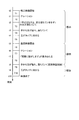
- FIG. 3 is a time chart showing an example of the timing at which each of the evaluation videos is displayed on the display unit.
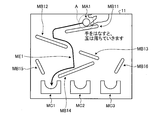
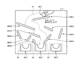
- FIG. 4 is a diagram showing an example of an evaluation video image displayed on the display unit by the display control unit according to the first embodiment.
- FIG. 5 is a diagram showing an example of an evaluation image displayed on the display unit by the display control unit according to the first embodiment.
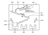
- FIG. 6 is a diagram showing an example of an evaluation video image displayed on the display unit by the display control unit according to the first embodiment.
- FIG. 7 is a diagram illustrating an evaluation image displayed on the display unit by the display control unit according to the first embodiment and a record of an example of a thought process of the subject.
- FIG. 8 is a diagram showing an example of the evaluation video image displayed on the display unit by the display control unit according to the first embodiment.
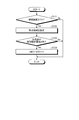
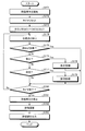
- FIG. 9 is a flowchart showing an example of the evaluation method according to the first embodiment.
- FIG. 10 is a flowchart showing an example of the teaching process.
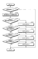
- FIG. 11 is a flowchart showing an example of the question process.
- FIG. 12 is a diagram showing an example of the evaluation video image displayed on the display unit by the display control unit according to the second embodiment.
- FIG. 13 is a diagram showing an example of an evaluation video image displayed on the display unit by the display control unit according to the second embodiment and a subject's thinking process.
- FIG. 14 is a flowchart showing an example of the evaluation method according to the second embodiment.
- FIG. 15 is a flowchart showing an example of the question process.
- FIG. 16 is a diagram showing an example of an evaluation video image displayed on the display unit by the display control unit according to the third embodiment.
- FIG. 17 is a flowchart showing an example of the evaluation method according to the third embodiment.
- FIG. 18 is a flowchart showing an example of the question process.
- the direction parallel to the first axis of the predetermined surface is the X-axis direction
- the direction parallel to the second axis of the predetermined surface orthogonal to the first axis is the Y-axis direction, and is orthogonal to each of the first axis and the second axis.
- the direction parallel to the third axis is the Z-axis direction.
- the predetermined surface includes the XY plane.
- FIG. 1 is a diagram schematically illustrating an example of the evaluation device 100 according to the present embodiment.
- the evaluation device 100 according to the present embodiment detects a subject's line of sight and uses the detection result to evaluate cognitive dysfunction and brain dysfunction.
- the evaluation apparatus 100 uses various methods such as a method of detecting the line of sight based on the position of the subject's pupil and the position of the corneal reflection image, or a method of detecting the line of sight based on the position of the subject's inner canthus and the position of the iris. The method can detect the line of sight of the subject.
- the evaluation device 100 includes a display device 10, an image acquisition device 20, a computer system 30, an output device 40, an input device 50, and an input/output interface device 60.
- the display device 10, the image acquisition device 20, the computer system 30, the output device 40, and the input device 50 perform data communication via the input/output interface device 60.
- the display device 10 and the image acquisition device 20 each have a drive circuit (not shown).
- the display device 10 includes a flat panel display such as a liquid crystal display (LCD) or an organic electroluminescence display (OLED).
- the display device 10 has a display unit 11.
- the display unit 11 displays information such as images.
- the display unit 11 is substantially parallel to the XY plane.
- the X-axis direction is the horizontal direction of the display unit 11
- the Y-axis direction is the vertical direction of the display unit 11
- the Z-axis direction is the depth direction orthogonal to the display unit 11.
- the display device 10 may be a head-mounted display device.
- a structure such as the image acquisition device 20 is arranged in the head mount module.
- the image acquisition device 20 acquires image data of the left and right eyeballs EB of the subject and transmits the acquired image data to the computer system 30.
- the image acquisition device 20 has a photographing device 21.
- the imaging device 21 acquires image data by imaging the left and right eyeballs EB of the subject.
- the imaging device 21 has various cameras according to the method of detecting the line of sight of the subject. For example, in the case of the method of detecting the line of sight based on the position of the subject's pupil and the position of the corneal reflection image, the imaging device 21 has an infrared camera and can transmit near-infrared light having a wavelength of 850 [nm], for example. It has an optical system and an image sensor capable of receiving near infrared light.
- the imaging device 21 has a visible light camera.
- the imaging device 21 outputs a frame synchronization signal.
- the cycle of the frame synchronization signal can be set to, for example, 20 [msec], but is not limited to this.
- the imaging device 21 can be configured as, for example, a stereo camera having a first camera 21A and a second camera 21B, but is not limited to this.
- the image acquisition device 20 has an illumination device 22 that illuminates the eyeball EB of the subject.
- the illumination device 22 includes an LED (light emitting diode) light source and can emit near infrared light having a wavelength of 850 [nm], for example.
- the illumination device 22 may not be provided.
- the illumination device 22 emits the detection light in synchronization with the frame synchronization signal of the imaging device 21.
- the lighting device 22 can be configured to include, for example, a first light source 22A and a second light source 22B, but is not limited to this.
- the computer system 30 centrally controls the operation of the evaluation device 100.
- the computer system 30 includes an arithmetic processing unit 30A and a storage device 30B.
- the arithmetic processing unit 30A includes a microprocessor such as a CPU (central processing unit).
- the storage device 30B includes memory or storage such as ROM (read only memory) and RAM (random access memory).
- the arithmetic processing device 30A performs arithmetic processing according to the computer program 30C stored in the storage device 30B.
- the output device 40 includes a display device such as a flat panel display.
- the output device 40 may include a printing device.
- the input device 50 is operated to generate input data.
- the input device 50 includes a keyboard or mouse for a computer system.
- the input device 50 may include a touch sensor provided in the display unit of the output device 40 that is a display device.
- the display device 10 and the computer system 30 are separate devices.
- the display device 10 and the computer system 30 may be integrated.
- the evaluation device 100 may include a tablet personal computer.
- the tablet personal computer may be equipped with a display device, an image acquisition device, a computer system, an input device, an output device, and the like.
- FIG. 2 is a functional block diagram showing an example of the evaluation device 100.
- the computer system 30 includes a display control unit 31, a gazing point detection unit 32, a region setting unit 33, a determination unit 34, a calculation unit 35, an evaluation unit 36, and an input/output control unit. It has 37 and the memory
- the functions of the computer system 30 are exhibited by the arithmetic processing unit 30A and the storage device 30B (see FIG. 1). Note that the computer system 30 may be provided with some functions outside the evaluation device 100.
- the display control unit 31 causes the display unit 11 to display a task that causes the subject to gaze at the final reaching point of the moving object.
- the display control unit 31 causes the display unit 11 of the display device 10 to display the evaluation video to be visually recognized by the subject.
- the evaluation video is a video of a task that causes the subject to gaze at the travel route and the final arrival point that follow the travel rules.
- the evaluation video includes a moving route and a final reaching point.
- the movement route is a route from the designated starting point to the final reaching point.
- the movement route is uniquely determined according to the movement rule.
- the evaluation image may include a moving object that moves along the moving path to the final reaching point.
- the evaluation image may further include a restraint object that restrains the movement path and a comparison arrival point different from the final arrival point.
- the movement rule may be, for example, a natural law or an artificial law such as a maze or an Amida lottery.
- the evaluation video includes a teaching video, a question video, and an answer video.
- the evaluation video is not limited to the video including all of the teaching video, the question video, and the answer video, and may be only the question video, for example.
- the display form of the evaluation video is not limited to the video, and a plurality of still images may be displayed in order.
- the gazing point detection unit 32 detects position data indicating the position of the gazing point of the subject.
- the gazing point detection unit 32 detects the line-of-sight vector of the subject defined by the three-dimensional global coordinate system based on the image data of the left and right eyeballs EB of the subject acquired by the image acquisition device 20.
- the gazing point detection unit 32 detects the position data of the intersection of the detected line-of-sight vector of the subject and the display unit 11 of the display device 10 as the position data of the gazing point of the subject. That is, in this embodiment, the position data of the gazing point is the position data of the intersection of the line-of-sight vector of the subject defined by the three-dimensional global coordinate system and the display unit 11 of the display device 10.
- the gazing point detection unit 32 detects the position data of the gazing point of the subject at every specified sampling period.
- This sampling cycle can be set to, for example, the cycle (for example, every 20 [msec]) of the frame synchronization signal output from the imaging device 21.
- the area setting unit 33 sets a specific area corresponding to the evaluation video displayed on the display unit 11 of the display device 10.
- the area setting unit 33 includes the moving object area A (see FIG. 5) corresponding to the moving object included in the evaluation video, and the moving path area A1 (corresponding to the moving path along which the moving object moves according to the moving rule). 6), the final arrival point area A4 (see FIG. 6) corresponding to the final arrival point of the moving object is set as the specific area.
- the set area is not displayed on the display unit 11, but the set area is not limited to this and may be displayed on the display unit 11.
- the determination unit 34 determines whether or not the gazing point is present in the specific region during the display period in which the task is displayed, in other words, the display period in which the display operation is performed, and makes the determination. Output the data.
- the determination unit 34 determines whether or not the gazing point exists in the moving object area A, the movement route area A1, and the final reaching point area A2, which are the specific areas, based on the position data of the gazing point. Then, the judgment data is output. For example, when determining that the gazing point exists in the specific area, the determination unit 34 adds “1” to the count value that is the determination value of the specific area and outputs the determination data.
- the determination unit 34 determines whether or not the gazing point exists in the specific region, for example, in each determination cycle.
- the determination cycle may be, for example, the cycle (for example, every 20 [msec]) of the frame synchronization signal output from the imaging device 21. That is, the determination cycle of the determination unit 34 is the same as the sampling cycle of the gazing point detection unit 32.
- the calculation unit 35 calculates the gazing point data indicating the progress of the movement of the gazing point during the display period based on the judgment data which is the judgment result of the judgment unit 34.
- the calculation unit 35 calculates, as the gazing point data, time data indicating the existence time of the gazing point in the specific region during the display period based on the determination data of the determination unit 34. More specifically, the calculation unit 35 calculates the first time data in which the gazing point was in the moving object area A in the time range T4 in which the teaching image is displayed, and the gazing point moving path in the time range T7 in which the question image is displayed.
- the second time data existing in the area A1 and the third time data having the gazing point in the final reaching point area A2 in the time range T7 are calculated as time data.
- the calculation unit 35 has a counter that counts the number of determination times when it is determined that the gazing point exists for the specific area. Further, the calculation unit 35 has a management timer that manages the playback time of the evaluation video and a detection timer that detects the elapsed time after the evaluation video is displayed on the display unit 11 of the display device 10.
- the evaluation unit 36 obtains evaluation data indicating the evaluation result of the subject based on the time data which is the gazing point data.
- the evaluation data is based on how much the subject is tracking the moving object displayed on the display unit 11 of the display device 10 in the display operation, whether the moving path of the moving object can be correctly estimated, and the final arrival point is correctly estimated. This is data indicating whether or not it has been completed.
- the input/output control unit 37 acquires data (image data of the eyeball EB, input data, etc.) from at least one of the image acquisition device 20 and the input device 50. Further, the input/output control unit 37 outputs data to at least one of the display device 10 and the output device 40. The input/output control unit 37 may output the task for the subject from the output device 40 such as a speaker.
- the storage unit 38 stores the above-mentioned position data, determination data, time data that is gazing point data, and evaluation data.
- the storage unit 38 displays the evaluation video, the process of detecting the position of the gazing point of the subject who observes the display unit, the process of setting the specific area on the display unit, and the position data of the gazing point. Based on, it is determined whether or not the gazing point is present in the specific region, a process of outputting the determination data, a process of determining the evaluation data of the subject based on the determination data, and a process of outputting the evaluation data, An evaluation program that causes a computer to execute is stored.
- the evaluation device 100 described above is used to evaluate the cognitive dysfunction and brain dysfunction of a subject.
- the content is a task that causes the subject to infer a place where a moving object presented at a predetermined position finally arrives via a predetermined movement route according to a movement rule.
- it is a task to make the examinee infer the place where the ball (moving object) MA1 arranged above the evaluation video finally arrives via a predetermined movement route while rolling according to the movement rules.
- the symptoms of cognitive dysfunction and brain dysfunction affect spatial cognitive ability, ability to correct guesses, and tracking ability.
- the movement path of the moving object can be accurately estimated by accurately recognizing the space shown in the evaluation image.
- the wrong guess can be corrected when the correct moving route is presented.
- the test subject is not a person with cognitive dysfunction and brain dysfunction, it is possible to track the moving object and the presented correct moving route.
- the space shown in the evaluation image may not be accurately recognized, and the movement path of the moving object may not be accurately estimated.
- test subject when the test subject is a person with cognitive dysfunction and brain dysfunction, the wrong guess may not be corrected even if the correct moving route is presented. Furthermore, when the test subject is a person with cognitive dysfunction and brain dysfunction, it may not be possible to track the moving object and the presented correct moving route.
- the display unit 11 of the display device 10 shows the ball MA1 before falling and the obstacles MB11 to MB16 which are restraints for restraining the movement path of the ball MA1.
- the subject is made to guess the cup in which the dropped ball MA1 is stored. It is possible to evaluate the subject by detecting whether or not the subject can gaze at the correct movement route and the final reaching point. Further, at the time of teaching or answering, it is possible to evaluate the subject by detecting whether the subject can gaze at the falling ball MA1.
- FIG. 3 shows the time chart of the evaluation video displayed when the subject is evaluated.
- FIG. 3 is a time chart showing an example of the timing at which each of the evaluation videos is displayed on the display unit.
- the time starts from t0 and shifts to t0 ⁇ t1 ⁇ t2 ⁇ t3 ⁇ t4 ⁇ t5 ⁇ t6 ⁇ t7 ⁇ t8 ⁇ t9 ⁇ t10.
- t0 or more and less than t1 are time range T1
- t1 or more and less than t2 are time range T2
- t2 or more and less than t3 are time range T3
- t3 or more and less than t4 are time range T4
- t4 or more and less than t5 are time range T5, t5 or more and t6.
- a time period less than T6 is a time range T6
- a time period between t6 and t7 is a time range T7
- a time period between t7 and t8 is a time range T8
- a time period between t8 and t9 is a time range T9
- a time period between t9 and t10 is a time range T10.
- FIG. 4 is displayed in the time range T1 to T3.
- the narration goes on, "If you release your hand, the balls will fall” (t1 in Fig. 3).
- the sentence “If you release your hand, the balls will fall” displayed in FIG. 4 disappears (t2 in FIG. 3).
- the narration may display characters or may output voice.
- FIG. 4 is a diagram showing an example of an evaluation image displayed on the display device 10 by the display control unit 31.
- the display control unit 31 causes the display unit 11 of the display device 10 to display a teaching image of a task that causes the subject to gaze at the moving route and the final reaching point that follow the moving rule.
- the display control unit 31 causes the display unit 11 of the display device 10 to display the ball MA1 that is a moving object before falling and the obstacle MB11 to be a restraint that restricts the moving path along which the ball MA1 moves.
- MB16 and the three cups MC1 to MC3 of the drop destination candidates are displayed.
- the ball MA1 is displayed above the display unit 11 of the display device 10.
- the ball MA1 falls due to gravity, and moves according to a moving rule in which the moving paths are restricted by the obstacles MB11 to MB16.
- the obstacles MB11 to MB16 are plate-like obstacles displayed below the ball MA1.
- the obstacles MB11 to MB16 are obstacles that guide the falling path of the ball MA1.
- the shapes of the obstacles MB11 to MB16 are not limited to this, and may be other articles.
- the obstacles MB11 to MB16 are arranged to be inclined with respect to the vertical direction.
- the ball MA1 falls on the obstacles MB11 to MB16 while rolling.
- the obstacles MB11 to MB16 are arranged apart from each other.
- the obstacles MB11 to MB16 guide the ball MA1 to the cup MC1 which is the final reaching point while controlling the fall of the ball MA1.
- the cup MC1 is displayed on the lower left portion of the display unit 11 of the display device 10.
- the cup MC1 has a cup shape that opens upward.
- the cup MC1 is displayed at a position where the ball MA1 separated from the hand falls and reaches while rolling on the obstacle MB11, the obstacle MB12, and the obstacle MB14.
- the cup MC2 and the cup MC3 are displayed in the lower center part and the lower right part of the display unit 11 of the display device 10.
- the cups MC2 and MC3 are cup-shaped and open upward.
- the cup MC2 and the cup MC3 have the same shape and size as the cup MC1.
- the cup MC2 and the cup MC3 are comparison reaching points, and are displayed at a position different from the position where the ball MA1 moving away from the hand falls and reaches while rolling on the obstacle MB11, the obstacle MB12, and the obstacle MB14. To be done.
- the display control unit 31 may display a teaching explanation in order to make the subject infer the movement route of the ball MA1 in the time range T1.
- the descriptive text is displayed, for example, in a region along the upper side of the display unit 11 of the display device 10.
- the description is displayed, for example, "If you release your hand, the balls will fall.” Instead of the description, a voice description may be used.
- the teaching image shown in FIG. 5 is displayed in the time range T4 to T5.
- the ball MA1 separates from the hand and rolls down (t3 in FIG. 3).
- the rolled ball MA1 finally fits in the cup MC1 (t4 in FIG. 3), and the teaching image ends (t5 in FIG. 3).
- FIG. 5 is a diagram showing an example of an evaluation image displayed on the display device 10 by the display control unit 31.
- FIG. 5 is displayed after FIG.
- the display control unit 31 causes the display unit 11 of the display device 10 to display an image in which the finger supporting the ball MA1 is released and the ball MA1 falls through the obstacles MB11 to MB16.
- the display control unit 31 causes the display unit 11 of the display device 10 to display an image in which the dropped ball MA1 fits in the left cup MC1 of the three cups MC1 to MC3 at the bottom of the screen.
- the area setting unit 33 sets the moving object area A corresponding to the ball MA1 as a specific area, which is not displayed on the display unit 11 of the display device 10, in the time range T4.
- the moving object area A is set to a range including the ball MA1, for example.
- the center position of the moving ball MA1 is known in advance.
- the area setting unit 33 sets an area of a predetermined size centered on the ball MA1 as a moving object area A that moves in accordance with the movement of the center position of the ball MA1.
- ⁇ Subject examines movement of ball MA1 in instruction video.
- a subject having cognitive dysfunction/cerebral dysfunction such as dementia
- the gazing point gathers in the moving object area A, it is understood that the subject has few problems in eye followability.
- the question video starts (t5 in Fig. 3). In the time range T6 to T8, the question video shown in FIG. 6 is displayed. Next, the narration "Where will the ball fall?" comes in (t6 in Fig. 3). Next, the sentence “Where does the ball fall?" is replaced with "Actually rolling" (t7 in Fig. 3). The question video ends (t8 in FIG. 3).
- the narration may display characters or may output voice.
- FIG. 6 is a diagram showing an example of an evaluation video image that the display control unit 31 displays on the display device 10.
- the display control unit 31 causes the display unit 11 of the display device 10 to move along a movement rule and finally reach the display unit 11.
- the display control unit 31 causes the display unit 11 of the display device 10 to display the ball MA1 before dropping, the obstacles MB21 to MB29 arranged differently from the teaching image, and the description.
- the description is displayed, for example, "where does the ball fall?" Instead of the description, a voice description may be used.
- the area setting unit 33 does not display on the display unit 11 of the display device 10 as the specific area, but the moving path area A1 corresponding to the moving path of the ball MA1 and the cup MC2 which is the final reaching point.
- the corresponding final arrival point area A2 is set.
- the area setting unit 33 sets the movement path area A1 based on, for example, the trajectory of the moving ball MA1.
- the movement path region A1 extends along the obstacle MB21, the obstacle MB22, the obstacle MB24, and the obstacle MB29 from the upper portion to the lower portion of the display unit 11 of the display device 10 in the figure, corresponding to the trajectory of the ball MA1. It is set in the open state.
- An area of a predetermined size centered on the cup MC2 is set as the final reaching point area A2.
- the examiner pays attention to which route the ball MA1 passes through and in which of the three cups MC1 to MC3 it will eventually fit.
- a subject with cognitive dysfunction/cerebral dysfunction such as dementia
- FIG. 7 is a diagram illustrating an evaluation image displayed on the display unit by the display control unit according to the first embodiment and a record of an example of a thought process of the subject.
- the thick arrow indicates the route MF1 of the subject's gazing point. From the route MF1, it can be seen that the subject has failed in guessing up to the final reaching point area A2 and repeatedly makes guessing at a branch point on the way to the final reaching point area A2. As described above, by using the route MF1 as a diagnosis aid, it is possible to more appropriately diagnose the subject.
- the answer video starts.
- the answer video shown in FIG. 8 is displayed.
- the ball MA1 separates from the hand and rolls down (t8 in FIG. 3).
- the ball MA1 fits in the cup MC2 (t9 in FIG. 3), the answer video ends and the evaluation video ends (t10 in FIG. 3).
- FIG. 8 is a diagram showing an example of an evaluation video image displayed on the display device 10 by the display control unit 31.
- FIG. 8 is displayed after FIG.
- the display control unit 31 causes the display unit 11 of the display device 10 to display the answer video of the task.
- the display control unit 31 causes the display unit 11 of the display device 10 to display, for example, "it actually rolls” as the explanatory text. Instead of the description, a voice description may be used.
- the display control unit 31 falls on the display unit 11 of the display device 10 while the ball MA1 is separated from the hand and falls along the obstacle MB21, the obstacle MB22, the obstacle MB24, and the obstacle MB29 while rolling.
- the moving route ME2 accommodated in MC2 is displayed.
- the answer video By displaying the answer video, it is possible to intuitively inform the subject of the movement route ME2 of the ball MA1.
- the answer video may not be displayed. In this way, the reproduction of the evaluation video is completed after the time range T10 has elapsed. In the time range T10, the fact that the evaluation video has ended may be displayed on the display unit 11 of the display device 10.
- the determination unit 34 determines whether the gazing point exists in the moving object area A and outputs the determination data.
- the calculation unit 35 calculates the first time data (moving object area existence time data) indicating the existence time in which the gazing point exists in the moving object area A, based on the determination data.
- the determination unit 34 determines whether or not the gazing point exists in the movement route area A1 or the final reaching point area A2, and outputs the determination data.
- the calculation unit 35 based on the determination data, the second time data indicating the time existing in the final arrival point area A2 (final arrival point area existence time data), and the gazing point is the movement route.
- Third time data (moving movement route area existence time data) indicating the time existing in the area A1 is calculated.
- the time data may be, for example, the number of times the determination unit 34 determines that the gazing point exists within the display period for the moving object region A, the movement route region A1, or the final arrival point region A2. it can. That is, the time data can be the number of gazing points detected in the moving object area A, the movement route area A1, or the final reaching point area A2 within the display period.
- the calculation unit 35 can calculate the time data by using the count result of the counter provided in the determination unit 34.
- the evaluation unit 36 when the evaluation unit 36 obtains evaluation data based on time data, the evaluation unit 36 can perform the following, for example.
- the counter provided in the calculation unit 35 counts the first time data in the time range T4, and counts the second time data and the third time data in the time range T7.
- the count result of the counter of the first time data is set to the counter value CNT1
- the count result of the counter of the second time data is set to the counter value CNT2
- the count result of the counter of the third time data is set to the counter value CNT3.
- the evaluation unit 36 can obtain the evaluation value ANS for obtaining the evaluation data as follows.
- the evaluation value ANS can be obtained by determining the length of time that the subject's gazing point was in the moving object area A.
- the time for gazing at the moving object region A becomes long.
- the longer the existence time of the gazing point existing in the moving object area A the larger the counter value CNT1.
- the evaluation value ANS can be obtained by determining the length of time during which the subject's gazing point was in the movement route area A1 or the final reaching point area A2.
- the evaluation value ANS can be obtained by determining whether or not the total value of the counter values CNT1, CNT2, CNT3 is greater than or equal to a predetermined value.
- the total value of the counter values CNT1, CNT2, and CNT3 is equal to or greater than a predetermined value, it can be evaluated that the subject is unlikely to have a cognitive dysfunction or a brain dysfunction. Further, when the total value of the counter values CNT1, CNT2, CNT3 is less than the predetermined value, it can be evaluated that the subject is highly likely to have cognitive dysfunction and brain dysfunction.
- the predetermined value for example, the average value of the counter values CNT1, CNT2, CNT3 of the subjects who are not cognitive dysfunction and brain dysfunction, or a value set based on the average value can be used. Further, as the predetermined value, for example, the lowest value of the counter values CNT1, CNT2, and CNT3 of a subject who is not a person with cognitive dysfunction or brain dysfunction may be used. In this case, a predetermined value may be set in advance for each age and sex, and a value according to the age and sex of the subject may be used.
- the evaluation unit 36 can also obtain the evaluation value ANS, for example, by the following formula (1).
- the counter value CNT1 is an evaluation as to whether the subject was able to track the ball MA1 at the time of teaching. Since the counter value CNT2 is a part of the correct answer, the evaluation of this count value is the highest. Since the counter value CNT3 is a part for guiding the correct answer, the evaluation of this count value is high.
- the constants K1, K2, K3 are constants for weighting.
- K1 ⁇ K3 ⁇ K2 can be set.
- the evaluation value ANS is obtained in which the influence of the third time data is weighted more than the influence of the first time data, and the influence of the second time data is weighted more than the influence of the third time data.
- the constants K1, K2, and K3 may be set to equal values (for example, 1), and the evaluation value ANS may be obtained without weighting.
- the tracking ability in the time range T4 to T5 the ability to correct the guess, and the time range T6 to T8. Spatial cognitive ability can be subdivided and evaluated.
- the evaluation unit 36 determines whether or not the evaluation value ANS is equal to or higher than a predetermined threshold value, and determines the evaluation. For example, when the evaluation value ANS is greater than or equal to the threshold value, it is possible to determine that the subject is unlikely to have cognitive dysfunction and brain dysfunction. In addition, when the evaluation value ANS is not greater than or equal to the predetermined threshold value, it is possible to determine that the subject is highly likely to have cognitive dysfunction and brain dysfunction.
- the input/output control unit 37 responds to, for example, “the subject is unlikely to be a person with cognitive dysfunction and brain dysfunction” in accordance with the evaluation result.
- the output device 40 is caused to output the character data such as “masu” or the character data such as “the subject is highly likely to have cognitive and brain dysfunction”.
- FIG. 9 is a flowchart showing an example of the evaluation method according to the first embodiment.
- the display control unit 31 starts the reproduction of the evaluation video (step S101).
- the display unit 11 of the display device 10 sequentially displays the evaluation videos shown in FIGS. 4, 5, 6, and 8. Then, the process proceeds to step S102.
- the calculation unit 35 resets the timer that manages the playback time of the evaluation video (step S102). More specifically, the calculation unit 35 controls the management timer that manages the reproduction time of the evaluation video and the period during which the currently reproduced evaluation video is included in the time range T1 to the time range T10 in the time chart shown in FIG. The detection timer for detecting whether or not they belong is reset, and each measurement is started. Then, the process proceeds to step S103.
- the determination unit 34 resets the counter values CNT1, CNT2, and CNT3 for measuring the time when the gazing point is within the specific area to 0 and starts the measurement (step S103).
- the gazing point is measured once for each frame of the camera, it is possible to measure the gazing time by counting for each frame corresponding to the area of gazing. Then, the process proceeds to step S104.
- the gazing point detection unit 32 displays the evaluation image displayed on the display unit 11 of the display device 10 in a state in which the subject is shown to the subject at every specified sampling cycle (for example, 20 [msec]).
- the position data of the gazing point of the subject in is detected (step S104). Then, the process proceeds to step S105.
- the calculation unit 35 considers the case where the gazing point cannot be detected due to blinking or the like, and determines whether or not the gazing point detection fails (step S105). When it is determined that the gazing point has failed to be detected (Yes in step S105), the calculation unit 35 proceeds to step S110. When it is determined that the detection of the gazing point has not failed (No in step S105), the calculation unit 35 proceeds to step S106.
- the calculation unit 35 determines whether or not it is a period for displaying the teaching video (step S106). More specifically, the calculation unit 35 determines whether or not the time range is T1 to T5 based on the detection result of the detection timer. When it is determined that the detection result of the detection timer corresponds to the time range T1 to T5 and the teaching image is displayed (Yes in step S106), the calculation unit 35 proceeds to step S108. When the calculation unit 35 determines that the detection result of the detection timer does not fall within the time range T1 to T5 and is not the period for displaying the teaching image (No in step S106), the process proceeds to step S107.
- the calculation unit 35 determines whether it is the period for displaying the question video (step S107). More specifically, the calculation unit 35 determines whether or not the time range is T6 to T8 based on the detection result of the detection timer. When the calculation unit 35 determines that the detection result of the detection timer corresponds to the time range T6 to T8 and the question video is displayed (Yes in step S107), the process proceeds to step S109. When the calculation unit 35 determines that the detection result of the detection timer does not fall within the time range T6 to T8 and is not the period for displaying the question video (No in step S107), the process proceeds to step S110.
- the arithmetic unit 35 executes a teaching process described later (step S108). Then, the process proceeds to step S110.
- the calculation unit 35 executes a question process described later (step S109). Then, the process proceeds to step S110.
- the arithmetic unit 35 determines whether or not the time when the reproduction of the evaluation video is completed has been reached based on the detection result of the management timer (step S110). When the calculation unit 35 determines that the time to complete the reproduction of the evaluation video has not been reached (No in step S110), the processes in step S104 and subsequent steps are repeated. When the calculation unit 35 determines that the time to complete the reproduction of the evaluation video has been reached (Yes in step S110), the process proceeds to step S111.
- the display control unit 31 stops the reproduction of the evaluation video (step S111). Then, the process proceeds to step S112.
- the evaluation unit 36 calculates the evaluation value ANS based on the time data obtained from the above processing result (step S112). Then, the process proceeds to step S113.
- the input/output control unit 37 outputs the evaluation data obtained by the evaluation unit 36 (step S113). This process ends.
- FIG. 10 is a flowchart showing an example of the teaching process.
- the calculation unit 35 determines whether or not it is within the time range T4 based on the detection result of the detection timer (step S121). When it is determined that the detection result of the detection timer is within the time range T4 (Yes in step S121), the calculation unit 35 proceeds to step S122. When the calculation unit 35 determines that the detection result of the detection timer is not within the time range T4 (No in step S121), the processing ends.
- step S121 When the calculation unit 35 determines that the detection result of the detection timer is within the time range T4 (Yes in step S121), the region setting unit 33 confirms whether the subject is gazing at the region to be viewed.
- the moving object area A is set as the specific area (step S122). Then, the process proceeds to step S123.
- the determination unit 34 determines whether or not the subject's gazing point exists in the moving object area A (step S123). When the determination unit 34 determines that the gazing point of the subject exists in the moving object area A (Yes in step S123), the process proceeds to step S124. When the determination unit 34 determines that the gazing point of the subject does not exist in the moving object area A (No in step S123), the process ends.
- the calculation unit 35 increments the counter value CNT1 by 1 (step S124).
- the calculation unit 35 outputs the counter value CNT1 as the determination data.
- FIG. 11 is a flowchart showing an example of the question process.
- the calculation unit 35 determines whether or not the time range is T7 based on the detection result of the detection timer (step S131). When it is determined that the detection result of the detection timer is within the time range T7 (Yes in step S131), the calculation unit 35 proceeds to step S132. When the calculation unit 35 determines that the detection result of the detection timer is not within the time range T7 (No in step S131), the processing ends.
- step S131 the region setting unit 33 confirms whether or not the subject is gazing at the region to be viewed.
- the movement route area A1 and the final arrival point area A2 are set as the specific areas (step S132). Then, the process proceeds to step S133.
- the judgment unit 34 judges whether or not the subject's gazing point exists in the final reaching point area A2 (step S133). When the determination unit 34 determines that the gazing point of the subject exists in the final reaching point area A2 (Yes in step S133), the process proceeds to step S135. When the determination unit 34 determines that the gazing point of the subject does not exist in the final reaching point area A2 (No in step S133), the process proceeds to step S134.
- step S134 determines whether the subject's gazing point exists in the movement route area A1 (step S134). ..
- the process proceeds to step S136.
- the determination unit 34 determines that the gazing point of the subject does not exist in the movement route area A1 (No in step S134)
- the process ends.
- the calculation unit 35 increments the counter value CNT2 by 1 (step S135).
- the calculation unit 35 outputs the counter value CNT2 as the determination data.
- the calculation unit 35 increments the counter value CNT3 by 1 (step S136).
- the calculation unit 35 outputs the counter value CNT3 as the determination data.
- the evaluation device 100 includes the display unit 11 that displays an image, the gazing point detection unit 32 that detects the position data of the gazing point of the subject, the movement route that moves according to the movement rule, and the final route.
- a display control unit 31 that performs a display operation of displaying a task that causes the subject to gaze at the arrival point and a movement route area A1 that corresponds to the movement path, and a final arrival point area A2 that corresponds to the final arrival point.
- a judgment unit Based on the area setting unit 33 to be set and the position data of the gazing point, a judgment unit that judges whether or not the gazing point exists in the movement route area A1 and the final reaching point area A2 during the display period in which the display operation is performed.
- a calculation unit 35 that calculates the gazing point data indicating the progress of the gazing point movement in the display period based on the determination result of the determination unit 34, and an evaluation unit that obtains the evaluation data of the subject based on the gazing point data. 36 and.
- the evaluation method includes a display step of displaying an image on the display unit 11, a gazing point detection step of detecting position data of a gazing point of a subject who observes the display unit 11, and a movement route that moves according to a movement rule. And a final reaching point, a display control step of performing a display operation of displaying a task on the display unit 11 for displaying a subject, a moving route area A1 corresponding to the moving route, and a final reaching point area A2 corresponding to the final reaching point. And a determination step of determining whether or not the gazing point exists in the movement route area A1 and the final reaching point area A2 during the display period in which the display operation is performed, based on the position data of the gazing point. And a calculation step of calculating gazing point data indicating the progress of movement of the gazing point in the display period based on the judgment result of the judgment step, and an evaluation step of obtaining evaluation data of the subject based on the gazing point data. ..
- the evaluation program includes a display step of displaying an image on the display unit 11, a gazing point detection step of detecting positional data of a gazing point of a subject who observes the display unit 11, and a movement route that moves according to a movement rule. And a final reaching point, a display control step of performing a display operation of displaying a task on the display unit 11 for displaying a subject, a moving route area A1 corresponding to the moving route, and a final reaching point area A2 corresponding to the final reaching point. And a determination step of determining whether or not the gazing point exists in the movement route area A1 and the final reaching point area A2 during the display period in which the display operation is performed, based on the position data of the gazing point. And a calculation step of calculating gazing point data indicating the progress of movement of the gazing point in the display period based on the judgment result of the judgment step, and an evaluation step of obtaining evaluation data of the subject based on the gazing point data. To run.
- time data in which the gazing point of the subject exists in the specific area during the display period is obtained, and evaluation data of the subject is obtained based on the time data. Therefore, the evaluation device 100 can evaluate the spatial cognitive ability, the ability to correct the guess, and the tracking ability of the subject based on the movement of the subject's line of sight during the display period. Accordingly, the evaluation device 100 can evaluate the subject with high accuracy.
- the calculation unit 35 uses the first time data in which the gazing point exists in the moving object area A in the time range T4T4 to T5 and the second time data in which the gazing point exists in the moving route area A1 in the time range T7. And the third time data in which the gazing point was present in the final reaching point region A2 in the time range T7, and the evaluation unit 36 calculates the evaluation data based on the first time data, the second time data, and the third time data. Ask for.
- the present embodiment can subdivide and evaluate the tracking ability in the time ranges T4 to T5, the ability to correct the guess, and the spatial cognitive ability in the time ranges T6 to T8.
- the evaluation unit 36 weights the influence of the second time data over the influence of the first time data, and further, the third time data rather than the influence of the second time data.
- the evaluation data is obtained by weighting the influence of.
- the area setting unit 33 sets the moving object area A as the specific area based on the trajectory of the ball MA1 in the time range T4 in which the teaching image is displayed. As a result, the moving object area A can be accurately set according to the movement of the ball MA1, and thus highly accurate time data can be obtained.
- the area setting unit 33 in the time range T7 in which the question video is displayed, the movement path area A1 corresponding to the movement path of the ball MA1 and the cup MC2 which is the final arrival point.
- the final reaching point area A2 corresponding to is set as the specific area.
- the display control unit 31 displays the correct moving route of the ball MA1 in the teaching image. Thereby, it is possible to inform the subject how the ball MA1 falls. By knowing how the ball MA1 falls, the subject has the opportunity to correct his guess if his guess is incorrect. This allows the ability to modify guesses to be included in the assessment.
- FIG. 12 is a diagram showing an example of an evaluation image displayed on the display device 10 by the display control unit 31 according to the second embodiment.
- FIG. 13 is a diagram showing an example of an evaluation video image displayed on the display unit by the display control unit according to the second embodiment and a subject's thinking process.
- FIG. 14 is a flowchart showing an example of the evaluation method according to the second embodiment.
- FIG. 15 is a flowchart showing an example of the question process.
- the evaluation device 100 has the same basic configuration as the evaluation device 100 of the first embodiment.
- This embodiment differs from the first embodiment in the processing of the area setting unit 33, the determination unit 34, and the evaluation unit 36.
- the area setting unit 33 sets a specific area and a comparison area corresponding to the evaluation video displayed on the display unit 11 of the display device 10.
- the area setting unit 33 sets the comparison area in at least a part of the area other than the specific area included in the evaluation video in the time range T7.
- the area setting unit 33 sets the comparison arrival point areas B1 and B2 corresponding to the comparison arrival points as the comparison areas in addition to the movement route area A1 and the final arrival point area A2. ..
- the determination unit 34 determines whether the gazing point exists in the movement route area A1 and at least the final reaching point area A2 among the final reaching point area A2 and the comparative reaching point areas B1 and B2. Whether or not.
- FIG. 12 is a diagram showing an example of an evaluation video image that the display control unit 31 displays on the display device 10.
- the area setting unit 33 sets the moving route area A1 and the final reaching point area A2 as the specific areas, which are not displayed on the display unit 11 of the display device 10. ..
- the area setting unit 33 sets comparison reaching point areas B1 and B2 as comparison areas.
- An area of a predetermined size centered on the cup MC1 is set as the comparison reaching point area B1.
- An area of a predetermined size centered on the cup MC3 is set as a comparison reaching point area B2.
- the gazing points gather in the comparison reaching point area B1 and the comparison reaching point area B2, it is understood that the subject cannot correctly guess the movement path of the ball MA1 and has a problem in the spatial cognitive ability. Further, by measuring the line of sight to the comparison reaching point area B1 and the comparison reaching point area B2, whether the path through which the ball MA1 falls can be quickly guessed at one time, or whether the guessing is repeated many times. It becomes possible to record the thought process of the subject and use it as an aid for diagnosis.
- the thick arrow indicates the route MF2 of the subject's gazing point. From the route MF2, the subject could not guess where the final reaching point area A2 was, and got lost between the final reaching point area A2, the comparative reaching point area B1 and the comparative reaching point area B2, and the eyes moved back and forth. Recognize. As described above, by using the route MF2 as an aid for diagnosis, it is possible to more appropriately diagnose the subject.
- the determination unit 34 determines whether or not the gazing point exists in the movement route area A1 and at least the final arrival point area A2 among the final arrival point area A2 and the comparison arrival point areas B1 and B2 in the time range T7. Then, the judgment data is output. In addition, in the time range T7, the calculation unit 35, based on the determination data, the second time data (final arrival point area existence time data) indicating the time when the gazing point exists in the final arrival point area A2, and the comparison arrival point. Third time data (comparison arrival point area existence time data) indicating the time when the gazing point exists in the areas B1 and B2, and fourth time data (moving moving path area) indicating the time when the gazing point exists in the moving path area A1. Presence time data) is calculated.
- the evaluation unit 36 can obtain the evaluation value ANS, for example, by the following equation (2).
- the counter value CNT1 is an evaluation as to whether the subject was able to track the ball MA1 at the time of teaching. Since the counter value CNT2 is a part of the correct answer, the evaluation of this count value is the highest. Since the counter value CNT3 is a wrong answer, the evaluation of this count value is low. Since the counter value CNT4 is a part that guides the correct answer, the evaluation of this count value is high.
- the constants K1, K2, K3 and K4 are constants for weighting.
- K1 ⁇ K3 ⁇ K4 ⁇ K2 can be set.
- the influence of the third time data is weighted more than the influence of the first time data
- the influence of the fourth time data is weighted more than the influence of the third time data
- the influence of the fourth time data is further weighted.
- an evaluation value ANS weighting the influence of the second time data.
- steps S141, S142, and steps S144 to S153 are the same as steps S101, S102, and steps S104 to S113 of the flowchart shown in FIG.
- the determination unit 34 resets the counter values CNT1, CNT2, CNT3, and CNT4 for measuring the time when the gazing point is in the specific area to 0 and starts the measurement (step S143). Then, the process proceeds to step S144.
- step S161, step S163, step S165, and step S166 is the same as the processing of step S131, step S133, step S134, and step S135 in FIG.
- step S161 the region setting unit 33 confirms whether the subject is gazing at the region to be viewed.
- the movement route area A1 and the final arrival point area A2 are set as the specific areas, and the comparison arrival point areas B1 and B2 are set as the comparison areas (step S162). Then, the process proceeds to step S163.
- the determination unit 34 determines whether the gazing point of the subject exists in the comparative reaching point areas B1 and B2 (Ste S164).
- the process proceeds to step S167.
- the determination unit 34 determines that the gazing point of the subject does not exist in the comparison reaching point regions B1 and B2 (No in step S164) (No in step S164).
- the calculation unit 35 increments the counter value CNT3 by 1 (step S167).
- the calculation unit 35 outputs the counter value CNT3 as the determination data.
- the calculation unit 35 increments the counter value CNT4 by 1 (step S168).
- the calculation unit 35 outputs the counter value CNT4 as the determination data.
- time data in which the subject's gazing point exists in the specific region and the comparison region during the display period is obtained, and the subject evaluation data is obtained based on the time data.
- FIG. 16 is a diagram showing an example of an evaluation image displayed on the display device 10 by the display control unit 31 according to the third embodiment.
- FIG. 17 is a flowchart showing an example of the evaluation method according to the third embodiment.
- FIG. 18 is a flowchart showing an example of the question process. In this embodiment, the processing of the area setting unit 33 and the evaluation unit 36 is different from that of the first embodiment.
- the area setting unit 33 sets a specific area and a comparison area corresponding to the evaluation video displayed on the display unit 11 of the display device 10.
- the region setting unit 33 specifies, in addition to the final reaching point region A2, the restricted object region A3 corresponding to the restricted object located on the moving path of the moving object among the restricted objects as the specific area.
- the area setting unit 33 sets, as a comparison area, the restricted object area B3 corresponding to the restricted object that is located out of the moving path of the moving object in the restricted object.
- the area setting unit 33 sets the comparison arrival point areas B1 and B2 corresponding to the comparison arrival points as comparison areas.
- the determination unit 34 determines that the gazing point is the restricted object area A3 or the restricted object area B3 and at least the final reaching point area A2 among the final reaching point area A2 and the comparative reaching point areas B1 and B2 based on the position data of the gazing point. It is determined whether or not there exists.
- FIG. 16 is a diagram showing an example of an evaluation video image that the display control unit 31 displays on the display device 10.
- the area setting unit 33 sets the final reaching point area A2 and the restrained object area A3 as the specific areas, which are not displayed on the display unit 11 of the display device 10. ..
- the region setting unit 33 sets the comparison reaching point regions B1 and B2 and the restrained object region B3 as the comparison regions.
- An area of a predetermined size centered on the restraint object that comes into contact when the ball MA1 falls is set as the restraint object area A3.
- An area of a predetermined size centered on the restraint object that does not come into contact when the ball MA1 falls is set as the restraint object area B3.
- the gazing points gather in the final reaching point area A2 and the restrained object area A3, it can be understood that the subject can correctly guess the movement path of the ball MA1 and there are few problems in the spatial cognitive ability. If the gazing points gather in the comparison reaching point regions B1 and B2 and the restrained object region B3, it is understood that the subject cannot correctly guess the movement path of the ball MA1 and has a problem in the spatial cognitive ability. Also, by measuring the line of sight to the restraint area A3 and the restraint area B3, whether the path through which the ball MA1 falls can be appropriately estimated or accidentally guessed, and the like Can be recorded and used as an aid in diagnosis.
- the gazing point exists in the restricted object region A3 or the restricted object region B3 and at least the final reaching point region A2 of the final reaching point region A2 and the comparative reaching point regions B1 and B2 in the time range T7. Whether or not each is determined, and the determination data is output.
- the calculation unit 35 in the time range T7, based on the determination data, the second time data (final arrival point area existence time data) indicating the time when the fixation point exists in the final arrival point area A2, Third time data (comparison arrival point region existence time data) indicating the time when the gazing point exists in the comparison reaching point regions B1 and B2, and fourth time data (constraining time) indicating the time when the gazing point exists in the restrained object region A3.
- Object region existing time data) and fifth time data (constrained object region existing time data) indicating the time when the gazing point exists in the restricted object region B3.
- the evaluation unit 36 can obtain the evaluation value ANS, for example, by the following formula (3).
- the counter value CNT1 is an evaluation as to whether the subject was able to track the ball MA1 at the time of teaching. Since the counter value CNT2 is a part of the correct answer, the evaluation of this count value is the highest. Since the counter value CNT3 is a wrong answer, the evaluation of this count value is low. Since the counter value CNT4 is a part that guides the correct answer, the evaluation of this count value is high. Since the counter value CNT5 is an incorrect answer, the evaluation of this count value is low.
- the constants K1, K2, K3, K4 and K5 are constants for weighting.
- the constants K1, K2, K3, K4, and K5 can be set to K1 ⁇ K5 ⁇ K3 ⁇ K4 ⁇ K2, for example.
- the influence of the fifth time data is weighted more than the influence of the first time data
- the influence of the third time data is weighted more than the influence of the fifth time data
- the influence of the third time data is weighted more than the influence of the third time data.
- An evaluation value ANS is obtained by weighting the influence of the 4-hour data and further weighting the influence of the second time data rather than the influence of the fourth time data.
- step S171, step S172, and steps S174 to S183 is the same as the processing of step S101, step S102, step S104 to step S113 of the flowchart shown in FIG.
- the determination unit 34 resets the counter values CNT1, CNT2, CNT3, CNT4, and CNT5 for measuring the time when the gazing point is within the specific area to 0 and starts the measurement (step S173). Then, the process proceeds to step S174.
- steps S191 to S194, step S197, and step S198 is the same as the processing of steps S161 to S164, step S166, and step S167 in FIG.
- step S194 determines whether the subject's gazing point exists in the restricted object region A3 (step S194). S195).
- the determination unit 34 determines that the gazing point of the subject exists in the restricted object region A3 (Yes in step S195)
- the process proceeds to step S199.
- step S195 determines whether the subject's gazing point exists in the restricted object region B3 (step S196).
- step S196 determines whether the subject's gazing point exists in the restricted object region B3.
- the calculation unit 35 increments the counter value CNT4 by 1 (step S199).
- the calculation unit 35 outputs the counter value CNT4 as the determination data.
- the calculation unit 35 increments the counter value CNT5 by 1 (step S200).
- the calculation unit 35 outputs the counter value CNT5 as the determination data.
- time data in which the subject's gazing point exists in the specific region and the comparison region during the display period is obtained, and the subject evaluation data is obtained based on the time data.
- the subject evaluation data is obtained based on the time data.
- the evaluation unit 36 may obtain the evaluation value ANS by individually determining each of the counter values CNT1, CNT2, CNT3, and the like.
- the evaluation device 100 is used as an evaluation device for evaluating the possibility of being a person with cognitive dysfunction and brain dysfunction has been described as an example, but the present invention is not limited to this.
- the evaluation apparatus 100 may be used as an evaluation apparatus that evaluates the spatial cognitive ability, the ability to correct guesses, and the tracking ability of a subject who is not a person with a cognitive dysfunction such as a developmental disability or a brain dysfunction.
- the restraint area corresponding to the restraint adjacent to the restraint area A3 and the restraint area corresponding to the restraint apart from the restraint area A3 are separately distinguished and injected. You may judge whether a viewpoint exists. This allows the subject to be evaluated with higher accuracy.
- the determination unit 34 may determine whether or not the gazing point exists in the moving object area A and output the determination data. This allows the subject to be evaluated with higher accuracy.
- the present disclosure can improve the certainty of the selection of the final result and the accuracy of the evaluation as a result by using the progress without judging only the final result. Further, the present disclosure can be used for a question such as a maze or Amida lottery in which the progress is displayed.
- the evaluation device, the evaluation method, and the evaluation program according to the present disclosure can be used for, for example, an evaluation device that detects the gaze of a subject and uses the detection result to evaluate cognitive dysfunction and brain dysfunction.
Landscapes
- Health & Medical Sciences (AREA)
- Life Sciences & Earth Sciences (AREA)
- Engineering & Computer Science (AREA)
- Veterinary Medicine (AREA)
- Biomedical Technology (AREA)
- Heart & Thoracic Surgery (AREA)
- Medical Informatics (AREA)
- Molecular Biology (AREA)
- Surgery (AREA)
- Animal Behavior & Ethology (AREA)
- General Health & Medical Sciences (AREA)
- Public Health (AREA)
- Pathology (AREA)
- Biophysics (AREA)
- Physics & Mathematics (AREA)
- Developmental Disabilities (AREA)
- Hospice & Palliative Care (AREA)
- Psychiatry (AREA)
- Psychology (AREA)
- Child & Adolescent Psychology (AREA)
- Educational Technology (AREA)
- Social Psychology (AREA)
- Neurology (AREA)
- Physiology (AREA)
- Neurosurgery (AREA)
- Human Computer Interaction (AREA)
- Ophthalmology & Optometry (AREA)
- Eye Examination Apparatus (AREA)
- Measurement Of The Respiration, Hearing Ability, Form, And Blood Characteristics Of Living Organisms (AREA)
Abstract
評価装置(100)は、表示部と、被験者の注視点の位置を検出する注視点検出部(32)と、移動物体の最終到達点を被験者に注視させる課題を表示部に表示する表示制御部(31)と、移動物体が移動規則に従って移動する移動経路に対応した移動経路領域と、最終到達点に対応した最終到達点領域とを設定する領域設定部(33)と、注視点の位置に基づいて、課題が表示される表示期間に注視点が移動経路領域及び最終到達点領域に存在するか否かの判定を行う判定部(34)と、判定部(34)における判定結果に基づいて、表示期間における注視点データを算出する演算部(35)と、注視点データに基づいて、被験者の評価データを求める評価部(36)とを備える。
Description
本発明は、評価装置、評価方法、及び評価プログラムに関する。
近年、認知症等の認知機能障害及び脳機能障害が増加傾向にあるといわれている。また、このような認知機能障害及び脳機能障害を早期に発見し、症状の重さを定量的に評価することが求められている。例えば、複数種類のオブジェクトを表示させて、その数を加算するなどして、その答を確認する装置が提案されている(例えば、特許文献1参照)。
上記の方法は、回答を選ぶだけの形態である。選んだ回答が、必然に選ばれた回答であるか、偶然に選ばれた回答であるかを検証することは困難である。このように、被験者の評価の精度には改善の余地がある。
本開示は、上記に鑑みてなされたものであり、被験者を高精度に評価することが可能な評価装置、評価方法、及び評価プログラムを提供することを目的とする。
本開示に係る評価装置は、表示部と、前記表示部を観察する被験者の注視点の位置を検出する注視点検出部と、移動物体の最終到達点を前記被験者に注視させる課題を前記表示部に表示する表示制御部と、前記移動物体が移動規則に従って移動する移動経路に対応した移動経路領域と、前記最終到達点に対応した最終到達点領域とを設定する領域設定部と、前記注視点の位置に基づいて、前記課題が表示される表示期間に前記注視点が前記移動経路領域及び前記最終到達点領域に存在するか否かの判定を行う判定部と、前記判定部における判定結果に基づいて、前記表示期間における注視点データを算出する演算部と、前記注視点データに基づいて、前記被験者の評価データを求める評価部とを備える。
本開示に係る評価方法は、表示部に画像を表示する表示ステップと、前記表示部を観察する被験者の注視点の位置を検出する注視点検出ステップと、移動物体の最終到達点を前記被験者に注視させる課題を前記表示部に表示する表示制御ステップと、前記移動物体が移動規則に従って移動する移動経路に対応した移動経路領域と、前記最終到達点に対応した最終到達点領域とを設定する領域設定ステップと、前記注視点の位置に基づいて、前記課題が表示される表示期間に前記注視点が前記移動経路領域及び前記最終到達点領域に存在するか否かの判定を行う判定ステップと、前記判定ステップによる判定結果に基づいて、前記表示期間における注視点データを算出する演算ステップと、前記注視点データに基づいて、前記被験者の評価データを求める評価ステップとを含む。
本開示に係る評価プログラムは、表示部に画像を表示する表示ステップと、前記表示部を観察する被験者の注視点の位置を検出する注視点検出ステップと、移動物体の最終到達点を前記被験者に注視させる課題を前記表示部に表示する表示制御ステップと、前記移動物体が移動規則に従って移動する移動経路に対応した移動経路領域と、前記最終到達点に対応した最終到達点領域とを設定する領域設定ステップと、前記注視点の位置に基づいて、前記課題が表示される表示期間に前記注視点が前記移動経路領域及び前記最終到達点領域に存在するか否かの判定を行う判定ステップと、前記判定ステップによる判定結果に基づいて、前記表示期間における注視点データを算出する演算ステップと、前記注視点データに基づいて、前記被験者の評価データを求める評価ステップとをコンピュータに実行させる。
本開示によれば、被験者を高精度に評価することが可能な評価装置、評価方法、及び評価プログラムを提供することができる。
以下、本開示に係る評価装置、評価方法、及び評価プログラムの実施形態を図面に基づいて説明する。なお、この実施形態によりこの発明が限定されるものではない。また、下記実施形態における構成要素には、当業者が置換可能かつ容易なもの、あるいは実質的に同一のものが含まれる。
以下の説明においては、三次元グローバル座標系を設定して各部の位置関係について説明する。所定面の第1軸と平行な方向をX軸方向とし、第1軸と直交する所定面の第2軸と平行な方向をY軸方向とし、第1軸及び第2軸のそれぞれと直交する第3軸と平行な方向をZ軸方向とする。所定面はXY平面を含む。
<第一実施形態>
[評価装置]
図1は、本実施形態に係る評価装置100の一例を模式的に示す図である。本実施形態に係る評価装置100は、被験者の視線を検出し、検出結果を用いることで認知機能障害及び脳機能障害の評価を行う。評価装置100は、例えば被験者の瞳孔の位置と角膜反射像の位置とに基づいて視線を検出する方法、又は被験者の目頭の位置と虹彩の位置とに基づいて視線を検出する方法等、各種の方法により被験者の視線を検出することができる。
[評価装置]
図1は、本実施形態に係る評価装置100の一例を模式的に示す図である。本実施形態に係る評価装置100は、被験者の視線を検出し、検出結果を用いることで認知機能障害及び脳機能障害の評価を行う。評価装置100は、例えば被験者の瞳孔の位置と角膜反射像の位置とに基づいて視線を検出する方法、又は被験者の目頭の位置と虹彩の位置とに基づいて視線を検出する方法等、各種の方法により被験者の視線を検出することができる。
図1に示すように、評価装置100は、表示装置10と、画像取得装置20と、コンピュータシステム30と、出力装置40と、入力装置50と、入出力インターフェース装置60とを備える。表示装置10、画像取得装置20、コンピュータシステム30、出力装置40及び入力装置50は、入出力インターフェース装置60を介してデータ通信を行う。表示装置10及び画像取得装置20は、それぞれ不図示の駆動回路を有する。
表示装置10は、液晶ディスプレイ(liquid crystal display:LCD)又は有機ELディスプレイ(organic electroluminescence display:OLED)のようなフラットパネルディスプレイを含む。本実施形態において、表示装置10は、表示部11を有する。表示部11は、画像等の情報を表示する。表示部11は、XY平面と実質的に平行である。X軸方向は表示部11の左右方向であり、Y軸方向は表示部11の上下方向であり、Z軸方向は表示部11と直交する奥行方向である。表示装置10は、ヘッドマウント型ディスプレイ装置であってもよい。ヘッドマウント型ディスプレイの場合、ヘッドマウントモジュール内に画像取得装置20のような構成が配置される。
画像取得装置20は、被験者の左右の眼球EBの画像データを取得し、取得した画像データをコンピュータシステム30に送信する。画像取得装置20は、撮影装置21を有する。撮影装置21は、被験者の左右の眼球EBを撮影することで画像データを取得する。撮影装置21は、被験者の視線を検出する方法に応じた各種カメラを有する。例えば被験者の瞳孔の位置と角膜反射像の位置とに基づいて視線を検出する方式の場合、撮影装置21は、赤外線カメラを有し、例えば波長850[nm]の近赤外光を透過可能な光学系と、その近赤外光を受光可能な撮像素子とを有する。また、例えば被験者の目頭の位置と虹彩の位置とに基づいて視線を検出する方式の場合、撮影装置21は、可視光カメラを有する。撮影装置21は、フレーム同期信号を出力する。フレーム同期信号の周期は、例えば20[msec]とすることができるが、これに限定されない。撮影装置21は、例えば第1カメラ21A及び第2カメラ21Bを有するステレオカメラの構成とすることができるが、これに限定されない。
また、例えば被験者の瞳孔の位置と角膜反射像の位置とに基づいて視線を検出する方式の場合、画像取得装置20は、被験者の眼球EBを照明する照明装置22を有する。照明装置22は、LED(light emitting diode)光源を含み、例えば波長850[nm]の近赤外光を射出可能である。なお、例えば被験者の目頭の位置と虹彩の位置とに基づいて視線ベクトルを検出する方式の場合、照明装置22は設けられなくてもよい。照明装置22は、撮影装置21のフレーム同期信号に同期するように検出光を射出する。照明装置22は、例えば第1光源22A及び第2光源22Bを有する構成とすることができるが、これに限定されない。
コンピュータシステム30は、評価装置100の動作を統括的に制御する。コンピュータシステム30は、演算処理装置30A及び記憶装置30Bを含む。演算処理装置30Aは、CPU(central processing unit)のようなマイクロプロセッサを含む。記憶装置30Bは、ROM(read only memory)及びRAM(random access memory)のようなメモリ又はストレージを含む。演算処理装置30Aは、記憶装置30Bに記憶されているコンピュータプログラム30Cに従って演算処理を実施する。
出力装置40は、フラットパネルディスプレイのような表示装置を含む。なお、出力装置40は、印刷装置を含んでもよい。入力装置50は、操作されることにより入力データを生成する。入力装置50は、コンピュータシステム用のキーボード又はマウスを含む。なお、入力装置50が表示装置である出力装置40の表示部に設けられたタッチセンサを含んでもよい。
本実施形態に係る評価装置100は、表示装置10とコンピュータシステム30とが別々の装置である。なお、表示装置10とコンピュータシステム30とが一体でもよい。例えば評価装置100がタブレット型パーソナルコンピュータを含んでもよい。この場合、当該タブレット型パーソナルコンピュータに、表示装置、画像取得装置、コンピュータシステム、入力装置、出力装置等が搭載されてもよい。
図2は、評価装置100の一例を示す機能ブロック図である。図2に示すように、コンピュータシステム30は、表示制御部31と、注視点検出部32と、領域設定部33と、判定部34と、演算部35と、評価部36と、入出力制御部37と、記憶部38とを有する。コンピュータシステム30の機能は、演算処理装置30A及び記憶装置30B(図1参照)によって発揮される。なお、コンピュータシステム30は、一部の機能が評価装置100の外部に設けられてもよい。
表示制御部31は、移動物体の最終到達点を被験者に注視させる課題を表示部11に表示させる。言い換えると、表示制御部31は、被験者に視認させる評価用映像を表示装置10の表示部11に表示させる。評価用映像は、移動規則に従って移動する移動経路と最終到達点とを被験者に注視させる課題の映像である。評価用映像には、移動経路と、最終到達点とを含む。移動経路は、指定された始点から最終到達点までの経路である。移動経路は、移動規則に従って一意に定まる。評価用映像には、移動経路を最終到達点まで移動経路に沿って移動する移動物体を含んでもよい。評価用映像には、さらに移動経路を拘束する拘束物と、最終到達点とは異なる比較到達点とを含んでもよい。移動規則は、例えば、自然法則でもよいし、迷路またはあみだくじのような人為的な法則であってもよい。評価用映像は、教示用映像と設問映像と回答映像とを含む。評価用映像は、教示用映像と設問映像と回答映像とのすべてを含む映像に限定されず、例えば、設問映像のみであってもよい。評価用映像の表示形態は、映像に限定されず、複数の静止画を順番に示してもよい。
注視点検出部32は、被験者の注視点の位置を示す位置データを検出する。本実施形態において、注視点検出部32は、画像取得装置20によって取得される被験者の左右の眼球EBの画像データに基づいて、三次元グローバル座標系で規定される被験者の視線ベクトルを検出する。注視点検出部32は、検出した被験者の視線ベクトルと表示装置10の表示部11との交点の位置データを、被験者の注視点の位置データとして検出する。つまり、本実施形態において、注視点の位置データは、三次元グローバル座標系で規定される被験者の視線ベクトルと、表示装置10の表示部11との交点の位置データである。注視点検出部32は、規定のサンプリング周期毎に被験者の注視点の位置データを検出する。このサンプリング周期は、例えば撮影装置21から出力されるフレーム同期信号の周期(例えば20[msec]毎)とすることができる。
領域設定部33は、表示装置10の表示部11に表示された評価用映像に対応した特定領域を設定する。本実施形態では、領域設定部33は、評価用映像に含まれる移動物体に対応した移動物体領域A(図5参照)、移動物体が移動規則に従って移動する移動経路に対応した移動経路領域A1(図6参照)、移動物体の最終到達点に対応した最終到達点領域A4(図6参照)を特定領域として設定する。設定された領域は、本実施形態では、表示部11に表示されないものとするが、これに限定されず、表示部11に表示してもよい。
判定部34は、注視点の位置データに基づいて、課題が表示される表示期間、言い換えると、表示動作が行われる表示期間に注視点が特定領域に存在するか否かをそれぞれ判定し、判定データを出力する。本実施形態では、判定部34は、注視点の位置データに基づいて、注視点が、特定領域である移動物体領域A、移動経路領域A1及び最終到達点領域A2に存在するか否かを判定し、判定データを出力する。例えば、判定部34は、注視点が特定領域に存在すると判定する場合、当該特定領域の判定値であるカウント値を「1」加算して判定データを出力する。判定部34は、例えば判定周期毎に注視点が特定領域に存在するか否かを判定する。判定周期としては、例えば撮影装置21から出力されるフレーム同期信号の周期(例えば20[msec]毎)とすることができる。つまり、判定部34の判定周期は、注視点検出部32のサンプリング周期と同一である。
演算部35は、判定部34の判定結果である判定データに基づいて、表示期間における注視点の移動の経過を示す注視点データを算出する。本実施形態では、演算部35は、注視点データとして、判定部34の判定データに基づいて、表示期間に注視点が特定領域に存在した存在時間を示す時間データを算出する。より詳しくは、演算部35は、教示映像が表示される時間範囲T4に注視点が移動物体領域Aに存在した第1時間データと、設問映像が表示される時間範囲T7に注視点が移動経路領域A1に存在した第2時間データと、時間範囲T7に注視点が最終到達点領域A2に存在した第3時間データとを時間データとして算出する。また、演算部35は、特定領域について注視点が存在すると判定された判定回数をカウントするカウンタを有する。また、演算部35は、評価用映像の再生時間を管理する管理タイマと、表示装置10の表示部11に評価用映像が表示されてからの経過時間を検出する検出タイマを有する。
評価部36は、注視点データである時間データに基づいて、被験者の評価結果を示す評価データを求める。評価データは、表示動作において表示装置10の表示部11に表示される移動物体に対して被験者がどの程度追視しているか、移動物体の移動経路を正しく推測できたか、最終到達点を正しく推測できたかを示すデータである。
入出力制御部37は、画像取得装置20及び入力装置50の少なくとも一方からのデータ(眼球EBの画像データ、入力データ等)を取得する。また、入出力制御部37は、表示装置10及び出力装置40の少なくとも一方にデータを出力する。入出力制御部37は、被験者に対する課題をスピーカ等の出力装置40から出力してもよい。
記憶部38は、上記の位置データ、判定データ、注視点データである時間データ、及び評価データを記憶する。また、記憶部38は、評価用映像を表示する処理と、表示部を観察する被験者の注視点の位置を検出する処理と、表示部において、特定領域を設定する処理と、注視点の位置データに基づいて、注視点が特定領域に存在するか否かをそれぞれ判定し、判定データを出力する処理と、判定データに基づいて、被験者の評価データを求める処理と、評価データを出力する処理とをコンピュータに実行させる評価プログラムを記憶する。
[評価方法]
次に、本実施形態に係る評価方法について説明する。本実施形態に係る評価方法では、上記の評価装置100を用いることにより、被験者の認知機能障害及び脳機能障害を評価する。本実施形態では、所定の位置に提示された移動物体が、移動規則に従って、所定の移動経路を経て最終的に到達する場所を、被検者に推測させる課題のコンテンツである。例えば、評価用映像の上部に配置された玉(移動物体)MA1が、移動規則に従って、転がりながら所定の移動経路を経て最終的に到達する場所を、被検者に推測させる課題である。
次に、本実施形態に係る評価方法について説明する。本実施形態に係る評価方法では、上記の評価装置100を用いることにより、被験者の認知機能障害及び脳機能障害を評価する。本実施形態では、所定の位置に提示された移動物体が、移動規則に従って、所定の移動経路を経て最終的に到達する場所を、被検者に推測させる課題のコンテンツである。例えば、評価用映像の上部に配置された玉(移動物体)MA1が、移動規則に従って、転がりながら所定の移動経路を経て最終的に到達する場所を、被検者に推測させる課題である。
認知機能障害及び脳機能障害の症状は、空間認知能力、推測を修正する能力、及び、追視能力に影響することが知られている。被験者が認知機能障害及び脳機能障害者ではない場合、評価用映像で示される空間を正確に認知して、移動物体の移動経路を正確に推測可能である。また、被験者が認知機能障害及び脳機能障害者ではない場合、正しい移動経路が提示されると、間違った推測を修正可能である。さらに、被験者が認知機能障害及び脳機能障害者ではない場合、移動物体及び提示された正しい移動経路を追視可能である。一方、被験者が認知機能障害及び脳機能障害者である場合、評価用映像で示される空間を正確に認知できず、移動物体の移動経路を正確に推測できないことがある。また、被験者が認知機能障害及び脳機能障害者である場合、正しい移動経路が提示されても、間違った推測を修正できないことがある。さらに、被験者が認知機能障害及び脳機能障害者である場合、移動物体及び提示された正しい移動経路を追視できないことがある。
このため、例えば以下の手順を行うことにより、被験者を評価することが可能である。まず、表示装置10の表示部11に、落下する前の玉MA1と、玉MA1が移動する移動経路を拘束する拘束物である障害物MB11~MB16とを示す。被験者に、落下した玉MA1が収容されるカップを推測させる。被験者が正しい移動経路と最終到達点とを注視できるかを検出することにより、被験者を評価することが可能である。また、教示時または回答時、被験者が落下する玉MA1を注視できるかを検出することにより、被験者を評価することが可能である。
図3に被験者の評価時に表示される評価用映像のタイムチャートを示す。図3は、表示部に評価用映像の各映像が表示されるタイミングの一例を示すタイムチャートである。時間は、t0からスタートして、t0→t1→t2→t3→t4→t5→t6→t7→t8→t9→t10と移行する。また、t0以上t1未満を時間範囲T1、t1以上t2未満を時間範囲T2、t2以上t3未満を時間範囲T3、t3以上t4未満を時間範囲T4、t4以上t5未満を時間範囲T5、t5以上t6未満を時間範囲T6、t6以上t7未満を時間範囲T7、t7以上t8未満を時間範囲T8、t8以上t9未満を時間範囲T9、t9以上t10未満を時間範囲T10としている。
まず、評価用映像が再生されると、教示映像が開始する(図3のt0)。時間範囲T1~T3では図4が表示されている。次に、「手をはなすと、玉は落ちていきます」とナレーションが入る(図3のt1)。次に、図4で表示されている、「手をはなすと、玉は落ちていきます」という文が消えていく(図3のt2)。ナレーションは、文字を表示してもよいし、音声を出力してもよい。
図4は、表示制御部31が表示装置10に表示させる評価用映像の一例を示す図である。表示制御部31は、表示装置10の表示部11に、移動規則に従って移動する移動経路と最終到達点とを被験者に注視させる課題の教示映像を表示させる。本実施形態では、表示制御部31は、表示装置10の表示部11に、移動物体である落下する前の玉MA1と、玉MA1が移動する移動経路を拘束する拘束物である障害物MB11~MB16と、落下先候補の3つのカップMC1~MC3とを表示させる。
玉MA1は、表示装置10の表示部11の上部に表示される。玉MA1は、手から離れると重力によって落下し、また、障害物MB11~MB16によって移動経路が拘束される移動規則に従って移動する。
障害物MB11~MB16は、玉MA1より下側に表示される板状の障害物である。障害物MB11~MB16は、玉MA1の落下の経路を誘導する障害物である。障害物MB11~MB16の形状は、これに限定されず、他の物品であってもよい。障害物MB11~MB16は、鉛直方向に対して傾斜して配置されている。障害物MB11~MB16の上を、玉MA1が転がりながら落下する。障害物MB11~MB16は、相互に離間して配置されている。障害物MB11~MB16は、玉MA1の落下を規制しながら、最終到達点であるカップMC1へ誘導する。
カップMC1は、表示装置10の表示部11の左下部に表示される。カップMC1は、上側に向かって開口したカップ状である。カップMC1は、手から離れた玉MA1が、障害物MB11、障害物MB12、障害物MB14の上を転がりながら落下して到達する位置に表示される。
カップMC2、カップMC3は、表示装置10の表示部11の中央下部と右下部とに表示される。カップMC2、カップMC3は、上側に向かって開口したカップ状である。カップMC2、カップMC3は、カップMC1と同じ形状、大きさである。カップMC2、カップMC3は比較到達点であり、手から離れた玉MA1が、障害物MB11、障害物MB12、及び、障害物MB14の上を転がりながら落下して到達する位置とは異なる位置に表示される。
また、表示制御部31は、時間範囲T1において、被験者に玉MA1の移動経路を推測させるため、教示の説明文を表示してもよい。説明文は、例えば、表示装置10の表示部11の上辺に沿った領域に表示される。説明文は、例えば、「手をはなすと、玉は落ちていきます」と表示される。説明文に代えて、音声で説明してもよい。
時間範囲T1~T3が経過した後、時間範囲T4~T5では、図5に示す教示映像が表示される。まず、手から玉MA1が離れて、転がり落ちていく(図3のt3)。転がり落ちた玉MA1は最終的にカップMC1に収まり(図3のt4)、教示映像が終了(図3のt5)する。
図5は、表示制御部31が表示装置10に表示させる評価用映像の一例を示す図である。図5は、図4の後に表示される。表示制御部31は、表示装置10の表示部11に、玉MA1を支えていた指が離され、玉MA1が障害物MB11~MB16の間を通って落下していく映像を表示させる。表示制御部31は、表示装置10の表示部11に、落下した玉MA1が画面下部にある3つのカップMC1~MC3のうち左のカップMC1に収まる映像を表示させる。
領域設定部33は、時間範囲T4において、特定領域として、表示装置10の表示部11には表示されないが、玉MA1に対応した移動物体領域Aを設定する。移動物体領域Aは、例えば玉MA1を含む範囲に設定される。移動する玉MA1の中心位置は予め分かっている。領域設定部33は、玉MA1を中心と設定した所定サイズの領域を、玉MA1の中心位置の移動に合わせて移動する移動物体領域Aとして設定する。
被験者は、教示映像において、玉MA1の動きを注視する。認知症など認知機能障害・脳機能障害のある被検者の場合、追視能力が低下するなどして、転がりながら落下する玉MA1を追視することが困難になる。移動物体領域Aに注視点が集まれば、被検者は、目の追従性に問題が少ないことがわかる。
教示映像の終了後、設問映像が開始する(図3のt5)。時間範囲T6~T8では、図6に示す設問映像が表示される。次に「玉は、どこに落ちるでしょう?」というナレーションが入る(図3のt6)。次に、「玉は、どこに落ちるでしょう?」という文が、「実際に転がします」に入れ替わる(図3のt7)。設問映像が終了(図3のt8)する。ナレーションは、文字を表示してもよいし、音声を出力してもよい。
図6は、表示制御部31が表示装置10に表示させる評価用映像の一例を示す図である表示制御部31は、表示装置10の表示部11に、移動規則に従って移動する移動経路と最終到達点とを被験者に注視させる課題の設問映像を表示させる。表示制御部31は、表示装置10の表示部11に、落下する前の玉MA1と、教示映像と異なる配置の障害物MB21~MB29と、説明文とを表示させる。説明文は、例えば、「玉は、どこに落ちるでしょう?」と表示される。説明文に代えて、音声で説明してもよい。
領域設定部33は、時間範囲T7において、特定領域として、表示装置10の表示部11には表示されないが、玉MA1の移動経路に対応した移動経路領域A1と、最終到達点であるカップMC2に対応した最終到達点領域A2とを設定する。領域設定部33は、例えば移動する玉MA1の軌跡に基づいて移動経路領域A1を設定する。移動経路領域A1は、玉MA1の軌跡に対応して、表示装置10の表示部11の図中の上部から下部まで、障害物MB21、障害物MB22、障害物MB24、障害物MB29に沿って延びた状態で設定される。カップMC2を中心と設定した所定サイズの領域が、最終到達点領域A2として設定される。
被検者は、設問映像において、玉MA1がどの経路を通り、最終的に3つのカップMC1~MC3のうち、どのカップに収まるのかを注視する。認知症など認知機能障害・脳機能障害のある被検者の場合、空間認知機能が低下するなどして、玉MA1がどの経路を通ることができるのかを正確に推測することが困難になる。移動経路領域A1と最終到達点領域A2とに注視点が集まれば、被検者が玉MA1の移動経路を正しく推測できており、空間認知能力に問題が少ないとわかる。
また、設問映像の表示時に視線を計測することで、一度で素早く玉MA1が落下する経路を推測できているのか、あるいは何度もスタート位置から推測を繰り返しているのかなど、被検者の思考過程を記録し、診断の補助とすることが可能になる。
ここで、図7を参照しながら、被験者の思考過程について説明する。図7は、第一実施形態に係る表示制御部が表示部に表示させる評価用映像と被験者の思考過程の一例の記録を示す図である。太い矢印は、被験者の注視点の経路MF1を示している。経路MF1から、被験者が、最終到達点領域A2までの推測に失敗し、最終到達点領域A2への途中の分岐点などで繰り返し推測を行っていることがわかる。このように、経路MF1を、診断の補助として使用することによって、被験者をより適切に診断することが可能になる。
設問映像の終了後、回答映像が開始する。時間範囲T9~T10では、図8に示す回答映像が表示される。まず、手から玉MA1が離れて転がり落ちていく(図3のt8)。次に、玉MA1がカップMC2に収まり(図3のt9)、回答映像が終了して評価用映像が終了する(図3のt10)。
図8は、表示制御部31が表示装置10に表示させる評価用映像の一例を示す図である。図8は、図6の後に表示される。表示制御部31は、表示装置10の表示部11に、課題の回答映像を表示させる。表示制御部31は、表示装置10の表示部11に、説明文として、例えば、「実際に転がします」と表示させる。説明文に代えて、音声で説明してもよい。表示制御部31は、表示装置10の表示部11に、例えば、玉MA1が手から離れて、障害物MB21、障害物MB22、障害物MB24、障害物MB29に沿って転がりながら落下して、カップMC2に収容される移動経路ME2を表示させる。
回答映像を表示することにより、被験者に対して、玉MA1の移動経路ME2を直観的に知らせることができる。なお、回答映像は表示しなくてもよい。このようにして、時間範囲T10が経過した後、評価用映像の再生が終了する。なお、時間範囲T10においては、評価用映像が終了した旨が表示装置10の表示部11に表示されてもよい。
上記の時間範囲T4において、判定部34は、注視点が移動物体領域Aに存在するか否かを判定し、判定データを出力する。また、演算部35は、時間範囲T4において、判定データに基づいて、注視点が移動物体領域Aに存在した存在時間を示す第1時間データ(移動物体領域存在時間データ)を算出する。
上記の時間範囲T7において、判定部34は、注視点が移動経路領域A1または最終到達点領域A2に存在するか否かをそれぞれ判定し、判定データを出力する。また、演算部35は、時間範囲T7において、判定データに基づいて、最終到達点領域A2に存在する時間を示す第2時間データ(最終到達点領域存在時間データ)、及び、注視点が移動経路領域A1に存在する時間を示す第3時間データ(移動移動経路領域存在時間データ)を算出する。
また、本実施形態において、判定部34において注視点が存在すると判定された回数が多いほど、移動物体領域A、移動経路領域A1または最終到達点領域A2に注視点が存在した存在時間が長いと推定することができる。したがって、本実施形態において、時間データは、例えば、移動物体領域A、移動経路領域A1または最終到達点領域A2について表示期間内に判定部34で注視点が存在すると判定された回数とすることができる。つまり、時間データは、表示期間内に移動物体領域A、移動経路領域A1または最終到達点領域A2で検出される注視点の数とすることができる。演算部35は、判定部34に設けられるカウンタのカウント結果を用いて時間データを算出可能である。
本実施形態において、評価部36は、時間データに基づいて評価データを求める場合、例えば、以下のように行うことができる。
まず、演算部35に設けられるカウンタは、時間範囲T4において第1時間データをカウントし、時間範囲T7において第2時間データ及び第3時間データをカウントする。ここで、第1時間データのカウンタのカウント結果をカウンタ値CNT1とし、第2時間データのカウンタのカウント結果をカウンタ値CNT2とし、第3時間データのカウンタのカウント結果をカウンタ値CNT3とする。
この場合、評価部36は、評価データを求めるための評価値ANSを、以下のように求めることができる。例えば、時間範囲T4において、被験者の注視点が移動物体領域Aに存在した時間の長さを判断することにより、評価値ANSを求めることができる。被験者が玉MA1に追従して視線を合わせ続けている場合、移動物体領域Aを注視する時間が長くなる。時間範囲T4において、移動物体領域Aに存在する注視点の存在時間が長いほど、カウンタ値CNT1の値が大きくなる。また、例えば、時間範囲T7において、被験者の注視点が移動経路領域A1または最終到達点領域A2に存在した時間の長さを判断することにより、評価値ANSを求めることができる。被験者が玉MA1の移動経路を正しく推測して視線を合わせ続けている場合、移動経路領域A1または最終到達点領域A2を注視する時間が長くなる。時間範囲T7において、移動経路領域A1または最終到達点領域A2に存在する注視点の存在時間が長いほど、カウンタ値CNT2とカウンタ値CNT3との値が大きくなる。これらにより、カウンタ値CNT1、CNT2、CNT3の合計値が所定値以上か否かを判断することで、評価値ANSを求めることができる。例えば、カウンタ値CNT1、CNT2、CNT3の合計値が所定値以上である場合、被験者が認知機能障害及び脳機能障害者である可能性は低いと評価することができる。また、カウンタ値CNT1、CNT2、CNT3の合計値が所定値未満である場合、被験者が認知機能障害及び脳機能障害者である可能性は高いと評価することができる。
なお、所定値としては、例えば認知機能障害及び脳機能障害者ではない被験者のカウンタ値CNT1、CNT2、CNT3の平均値、または当該平均値に基づいて設定される値等を用いることができる。また、所定値として、例えば認知機能障害及び脳機能障害者ではない被験者のカウンタ値CNT1、CNT2、CNT3の最低値を用いてもよい。この場合、予め所定値を年齢及び性別ごとに設定しておき、被験者の年齢及び性別に応じた値を用いるようにしてもよい。
また、評価部36は、例えば以下の式(1)により評価値ANSを求めることができる。カウンタ値CNT1は、教示時に被験者が玉MA1を追視できていたかの評価となる。カウンタ値CNT2は、正解の回答の部分となるので、この計数値の評価が最も高くなる。カウンタ値CNT3は、正解の回答を導く部分となるので、この計数値の評価が高くなる。
ANS=(K1×CNT1)+(K2×CNT2)+(K3×CNT3)・・・(1)
上記の式(1)において、定数K1、K2、K3は、重みづけのための定数である。定数K1、K2、K3については、例えば、K1<K3<K2とすることができる。この場合、第1時間データの影響よりも第3時間データの影響に重みをつけ、さらに、第3時間データの影響よりも第2時間データの影響に重みをつけた評価値ANSを求める。
なお、定数K1、K2、K3をそれぞれ等しい値(例えば、1)とし、重みづけをすることなく評価値ANSを求めてもよい。このように、第1時間データ、第2時間データ及び第3時間データに基づいて評価データを求めることにより、時間範囲T4~T5における追視能力、推測を修正する能力、時間範囲T6~T8における空間認知能力を細分化して評価することができる。
評価部36は、評価値ANSが所定のしきい値以上か否かを判断して、評価の判定を行う。例えば評価値ANSがしきい値以上である場合、被験者が認知機能障害及び脳機能障害である可能性は低いと評価を判定することができる。また、評価値ANSが所定のしきい値以上ではない場合、被験者が認知機能障害及び脳機能障害である可能性は高いと評価を判定することができる。
本実施形態において、入出力制御部37は、評価部36が評価結果を出力した場合、評価結果に応じて、例えば「被験者は認知機能障害及び脳機能障害者である可能性が低いと思われます」の文字データや、「被験者は認知機能障害及び脳機能障害者である可能性が高いと思われます」の文字データ等を出力装置40に出力させる。
次に、本実施形態に係る評価方法の一例について、図9を参照しながら説明する。図9は、第一実施形態に係る評価方法の一例を示すフローチャートである。
表示制御部31は、評価用映像の再生を開始させる(ステップS101)。表示装置10の表示部11には、図4、図5、図6、図8に示す評価用映像が順に表示される。そして、ステップS102に進む。
演算部35は、評価用映像の再生時間を管理するタイマをリセットする(ステップS102)。より詳しくは、演算部35は、評価用映像の再生時間を管理する管理タイマと、図3に示すタイムチャートにおける時間範囲T1~時間範囲T10のうち現在再生されている評価用映像がどの期間に属するかを検出する検出タイマとをリセットして、それぞれ計測を開始させる。そして、ステップS103に進む。
判定部34は、特定領域内に注視点がある時間を測定するためのカウンタ値CNT1、CNT2、CNT3をそれぞれ0にリセットして計測を開始させる(ステップS103)。本実施形態は、カメラの1フレームごとに1回の注視点測定を行うため、1フレームごとに、注視している領域に対応して計数することにより注視時間を計測することが可能である。そして、ステップS104に進む。
注視点検出部32は、表示装置10の表示部11に表示された評価用映像を被験者に見せた状態で、規定のサンプリング周期(例えば20[msec])毎に、表示装置10の表示部11における被験者の注視点の位置データを検出する(ステップS104)。そして、ステップS105に進む。
演算部35は、瞬きなどにより注視点を検出できない場合を考量して、注視点の検出に失敗したか否かを判定する(ステップS105)。演算部35は、注視点の検出に失敗したと判定する場合(ステップS105でYes)、ステップS110に進む。演算部35は、注視点の検出に失敗していないと判定する場合(ステップS105でNo)、ステップS106に進む。
注視点の検出に失敗していないと判定する場合(ステップS105でNo)、演算部35は、教示映像を表示する期間であるか否かを判定する(ステップS106)。より詳しくは、演算部35は、検出タイマの検出結果により、時間範囲T1~T5であるか否かの判定を行う。演算部35は、検出タイマの検出結果が時間範囲T1からT5までの範囲に該当し、教示映像を表示する期間であると判断する場合(ステップS106のYes)、ステップS108に進む。演算部35は、検出タイマの検出結果が時間範囲T1からT5までの範囲に該当せず、教示映像を表示する期間ではないと判断する場合(ステップS106のNo)、ステップS107に進む。
教示映像を表示する期間ではないと判断された場合(ステップS106のNo)、演算部35は、設問映像を表示する期間であるか否かを判定する(ステップS107)。より詳しくは、演算部35は、検出タイマの検出結果により、時間範囲T6~T8であるか否かの判定を行う。演算部35は、検出タイマの検出結果が時間範囲T6からT8までの範囲に該当し、設問映像を表示する期間であると判断する場合(ステップS107のYes)、ステップS109に進む。演算部35は、検出タイマの検出結果が時間範囲T6からT8までの範囲に該当せず、設問映像を表示する期間ではないと判断する場合(ステップS107のNo)、ステップS110に進む。
演算部35は、後述する教示処理を実行する(ステップS108)。そして、ステップS110に進む。
演算部35は、後述する設問処理を実行する(ステップS109)。そして、ステップS110に進む。
演算部35は、管理タイマの検出結果に基づいて、評価用映像の再生が完了する時刻に到達したか否かを判断する(ステップS110)。演算部35により評価用映像の再生が完了する時刻に到達していないと判断された場合(ステップS110のNo)、上記のステップS104以降の処理を繰り返し行う。演算部35により評価用映像の再生が完了する時刻に到達したと判断された場合(ステップS110のYes)、ステップS111に進む。
表示制御部31は、評価用映像の再生を停止させる(ステップS111)。そして、ステップS112に進む。
評価部36は、上記の処理結果から得られる時間データに基づいて、評価値ANSを算出する(ステップS112)。そして、ステップS113に進む。
入出力制御部37は、評価部36で求められた評価データを出力する(ステップS113)。この処理を終了する。
つづいて、教示処理の一例について、図10を参照しながら説明する。図10は、教示処理の一例を示すフローチャートである。
演算部35は、検出タイマの検出結果により、時間範囲T4であるか否かの判定を行う(ステップS121)。演算部35は、検出タイマの検出結果が、時間範囲T4であると判定する場合(ステップS121でYes)、ステップS122に進む。演算部35は、検出タイマの検出結果が、時間範囲T4ではないと判定する場合(ステップS121でNo)、処理を終了する。
演算部35により検出タイマの検出結果が時間範囲T4であると判断された場合(ステップS121のYes)、領域設定部33は、被検者が見るべき領域を注視しているかを確認するため、特定領域として、移動物体領域Aを設定する(ステップS122)。そして、ステップS123に進む。
判定部34は、被験者の注視点が移動物体領域Aに存在するか否かを判定する(ステップS123)。判定部34が被験者の注視点が移動物体領域Aに存在すると判定する場合(ステップS123でYes)、ステップS124に進む。判定部34が被験者の注視点が移動物体領域Aに存在しないと判定する場合(ステップS123でNo)、処理を終了する。
判定部34により注視点が移動物体領域Aに存在すると判定された場合(ステップS123のYes)、演算部35は、カウンタ値CNT1を+1する(ステップS124)。演算部35は、判定データとしてカウンタ値CNT1を出力する。
つづいて、設問処理の一例について、図11を参照しながら説明する。図11は、設問処理の一例を示すフローチャートである。
演算部35は、検出タイマの検出結果により、時間範囲T7であるか否かの判定を行う(ステップS131)。演算部35は、検出タイマの検出結果が、時間範囲T7であると判定する場合(ステップS131のYes)、ステップS132に進む。演算部35は、検出タイマの検出結果が、時間範囲T7ではないと判定する場合(ステップS131でNo)、処理を終了する。
演算部35により検出タイマの検出結果が時間範囲T7であると判断された場合(ステップS131のYes)、領域設定部33は、被検者が見るべき領域を注視しているかを確認するため、特定領域として、移動経路領域A1と最終到達点領域A2とを設定する(ステップS132)。そして、ステップS133に進む。
判定部34は、被験者の注視点が最終到達点領域A2に存在するか否かを判定する(ステップS133)。判定部34が被験者の注視点が最終到達点領域A2に存在すると判定する場合(ステップS133でYes)、ステップS135に進む。判定部34が被験者の注視点が最終到達点領域A2に存在しないと判定する場合(ステップS133でNo)、ステップS134に進む。
判定部34が被験者の注視点が最終到達点領域A2に存在しないと判定する場合(ステップS133でNo)、被験者の注視点が移動経路領域A1に存在するか否かを判定する(ステップS134)。判定部34が被験者の注視点が移動経路領域A1に存在すると判定する場合(ステップS134でYes)、ステップS136に進む。判定部34が被験者の注視点が移動経路領域A1に存在しないと判定する場合(ステップS134でNo)、処理を終了する。
判定部34により注視点が最終到達点領域A2に存在すると判定された場合(ステップS133のYes)、演算部35は、カウンタ値CNT2を+1する(ステップS135)。演算部35は、判定データとしてカウンタ値CNT2を出力する。
判定部34により注視点が移動経路領域A1に存在すると判定された場合(ステップS134のYes)、演算部35は、カウンタ値CNT3を+1する(ステップS136)。演算部35は、判定データとしてカウンタ値CNT3を出力する。
以上のように、本実施形態に係る評価装置100は、画像を表示する表示部11と、被験者の注視点の位置データを検出する注視点検出部32と、移動規則に従って移動する移動経路と最終到達点とを被験者に注視させる課題を表示部11に表示する表示動作を行う表示制御部31と、移動経路に対応した移動経路領域A1と、最終到達点に対応した最終到達点領域A2とを設定する領域設定部33と、注視点の位置データに基づいて、表示動作が行われる表示期間に注視点が移動経路領域A1及び最終到達点領域A2に存在するか否かの判定を行う判定部34と、判定部34における判定結果に基づいて、表示期間における注視点の移動の経過を示す注視点データを算出する演算部35と、注視点データに基づいて、被験者の評価データを求める評価部36とを備える。
本実施形態に係る評価方法は、表示部11に画像を表示する表示ステップと、表示部11を観察する被験者の注視点の位置データを検出する注視点検出ステップと、移動規則に従って移動する移動経路と最終到達点とを被験者に注視させる課題を表示部11に表示する表示動作を行う表示制御ステップと、移動経路に対応した移動経路領域A1と、最終到達点に対応した最終到達点領域A2とを設定する領域設定ステップと、注視点の位置データに基づいて、表示動作が行われる表示期間に注視点が移動経路領域A1及び最終到達点領域A2に存在するか否かの判定を行う判定ステップと、判定ステップによる判定結果に基づいて、表示期間における注視点の移動の経過を示す注視点データを算出する演算ステップと、注視点データに基づいて、被験者の評価データを求める評価ステップとを含む。
本実施形態に係る評価プログラムは、表示部11に画像を表示する表示ステップと、表示部11を観察する被験者の注視点の位置データを検出する注視点検出ステップと、移動規則に従って移動する移動経路と最終到達点とを被験者に注視させる課題を表示部11に表示する表示動作を行う表示制御ステップと、移動経路に対応した移動経路領域A1と、最終到達点に対応した最終到達点領域A2とを設定する領域設定ステップと、注視点の位置データに基づいて、表示動作が行われる表示期間に注視点が移動経路領域A1及び最終到達点領域A2に存在するか否かの判定を行う判定ステップと、判定ステップによる判定結果に基づいて、表示期間における注視点の移動の経過を示す注視点データを算出する演算ステップと、注視点データに基づいて、被験者の評価データを求める評価ステップとをコンピュータに実行させる。
本実施形態によれば、表示期間に被験者の注視点が特定領域に存在する時間データが求められ、時間データに基づいて被験者の評価データを求められる。このため、評価装置100は、表示期間における被験者の視線の動きにより、被験者の空間認知能力、推測を修正する能力、及び、追視能力を評価することができる。これにより、評価装置100は、被験者の評価を高精度に行うことが可能となる。
本実施形態では、演算部35は、時間範囲T4T4~T5に注視点が移動物体領域Aに存在した第1時間データと、時間範囲T7に注視点が移動経路領域A1に存在した第2時間データと、時間範囲T7に注視点が最終到達点領域A2に存在した第3時間データとを算出し、評価部36は、第1時間データ、第2時間データ及び第3時間データに基づいて評価データを求める。これにより、本実施形態は、時間範囲T4~T5における追視能力、推測を修正する能力、時間範囲T6~T8における空間認知能力を細分化して評価することができる。
また、本実施形態に係る評価装置100において、評価部36は、第1時間データの影響よりも第2時間データの影響に重みをつけ、さらに、第2時間データの影響よりも第3時間データの影響に重みをつけて評価データを求める。第2時間データ、第3時間データに重みをつけて評価値ANSを求めることにより、効率的に評価データを得ることができる。
また、本実施形態に係る評価装置100において、領域設定部33は、教示映像が表示される時間範囲T4において、玉MA1の軌跡に基づいて移動物体領域Aを特定領域として設定する。これにより、玉MA1の移動に応じて移動物体領域Aを精度よく設定することができるため、精度の高い時間データを得ることができる。
また、本実施形態に係る評価装置100において、領域設定部33は、設問映像が表示される時間範囲T7において、玉MA1の移動経路に対応した移動経路領域A1と、最終到達点であるカップMC2に対応した最終到達点領域A2とを特定領域として設定する。これにより、移動経路領域A1と最終到達点領域A2とを精度よく設定することができるため、精度の高い時間データを得ることができる。
また、本実施形態に係る評価装置100において、表示制御部31は、教示映像において、玉MA1の正しい移動経路を表示させる。これにより、玉MA1がどのように落下するかを被験者に知らせることができる。被験者は、玉MA1がどのように落下するかを知ることにより、自身の推測が誤っている場合、推測を修正する機会が得られる。これにより、推測を修正する能力を、評価に含めることができる。
<第二実施形態>
図12ないし図15を参照しながら、本実施形態に係る評価装置100について説明する。図12は、第二実施形態に係る表示制御部31が表示装置10に表示させる評価用映像の一例を示す図である。図13は、第二実施形態に係る表示制御部が表示部に表示させる評価用映像と被験者の思考過程の一例を示す図である。図14は、第二実施形態に係る評価方法の一例を示すフローチャートである。図15は、設問処理の一例を示すフローチャートである。評価装置100は、基本的な構成は第一実施形態の評価装置100と同様である。以下の説明においては、第一実施形態の評価装置100と同様の構成要素には、同一の符号または対応する符号を付し、その詳細な説明は省略する。本実施形態は、領域設定部33と判定部34と評価部36との処理が、第一実施形態と異なる。
図12ないし図15を参照しながら、本実施形態に係る評価装置100について説明する。図12は、第二実施形態に係る表示制御部31が表示装置10に表示させる評価用映像の一例を示す図である。図13は、第二実施形態に係る表示制御部が表示部に表示させる評価用映像と被験者の思考過程の一例を示す図である。図14は、第二実施形態に係る評価方法の一例を示すフローチャートである。図15は、設問処理の一例を示すフローチャートである。評価装置100は、基本的な構成は第一実施形態の評価装置100と同様である。以下の説明においては、第一実施形態の評価装置100と同様の構成要素には、同一の符号または対応する符号を付し、その詳細な説明は省略する。本実施形態は、領域設定部33と判定部34と評価部36との処理が、第一実施形態と異なる。
領域設定部33は、表示装置10の表示部11に表示された評価用映像に対応した特定領域及び比較領域を設定する。領域設定部33は、時間範囲T7において、評価用映像に含まれる特定領域以外の領域の少なくとも一部に比較領域を設定する。本実施形態では、時間範囲T7において、領域設定部33は、移動経路領域A1と最終到達点領域A2とに加えて、比較到達点に対応した比較到達点領域B1、B2を比較領域として設定する。
判定部34は、注視点の位置データに基づいて、注視点が移動経路領域A1と、最終到達点領域A2及び比較到達点領域B1、B2のうち少なくとも最終到達点領域A2とに存在するか否かの判定を行う。
図12は、表示制御部31が表示装置10に表示させる評価用映像の一例を示す図である。図12が表示されている時間範囲T7において、領域設定部33は、特定領域として、表示装置10の表示部11には表示されないが、移動経路領域A1と、最終到達点領域A2とを設定する。領域設定部33は、表示装置10の表示部11には表示されないが、比較領域として、比較到達点領域B1、B2を設定する。カップMC1を中心と設定した所定サイズの領域が、比較到達点領域B1として設定されている。カップMC3を中心と設定した所定サイズの領域が、比較到達点領域B2として設定されている。
比較到達点領域B1と比較到達点領域B2とに注視点が集まれば、被検者が玉MA1の移動経路を正しく推測できておらず、空間認知能力に問題を有するとわかる。また、比較到達点領域B1と比較到達点領域B2とに対する視線を計測することで、一度で素早く玉MA1が落下する経路を推測できているのか、あるいは何度も推測を繰り返しているのかなど、被検者の思考過程を記録し、診断の補助とすることが可能になる。
ここで、図13を参照しながら、被験者の思考過程について説明する。太い矢印は、被験者の注視点の経路MF2を示している。経路MF2から、被験者が、最終到達点領域A2がどこになるか推測できず、最終到達点領域A2と、比較到達点領域B1と比較到達点領域B2とで迷ってしまい、視線が行き来したことがわかる。このように、経路MF2を、診断の補助として使用することによって、被験者をより適切に診断することが可能になる。
判定部34は、時間範囲T7において、注視点が移動経路領域A1と、最終到達点領域A2及び比較到達点領域B1、B2のうち少なくとも最終到達点領域A2とに存在するか否かをそれぞれ判定し、判定データを出力する。また、演算部35は、時間範囲T7において、判定データに基づいて、最終到達点領域A2に注視点が存在する時間を示す第2時間データ(最終到達点領域存在時間データ)と、比較到達点領域B1、B2に注視点が存在する時間を示す第3時間データ(比較到達点領域存在時間データ)と、注視点が移動経路領域A1に存在する時間を示す第4時間データ(移動移動経路領域存在時間データ)を算出する。
評価部36は、例えば以下の式(2)により評価値ANSを求めることができる。カウンタ値CNT1は、教示時に被験者が玉MA1を追視できていたかの評価となる。カウンタ値CNT2は、正解の回答の部分となるので、この計数値の評価が最も高くなる。カウンタ値CNT3は、間違った回答であるので、この計数値の評価が低くなる。カウンタ値CNT4は、正解の回答を導く部分となるので、この計数値の評価が高くなる。
ANS=(K1×CNT1)+(K2×CNT2)+(K3×CNT3)+(K4×CNT4)・・・(2)
上記の式(2)において、定数K1、K2、K3、K4は、重みづけのための定数である。定数K1、K2、K3、K4については、例えば、K1<K3<K4<K2とすることができる。この場合、第1時間データの影響よりも第3時間データの影響に重みをつけ、第3時間データの影響よりも第4時間データの影響に重みをつけ、さらに、第4時間データの影響よりも第2時間データの影響に重みをつけた評価値ANSを求める。
次に、本実施形態に係る評価方法の一例について、図14を参照しながら説明する。ステップS141、ステップS142、ステップS144ないしステップS153の処理は、図9に示すフローチャートのステップS101、ステップS102、ステップS104ないしステップS113と同様の処理である。
判定部34は、特定領域内に注視点がある時間を測定するためのカウンタ値CNT1、CNT2、CNT3、CNT4をそれぞれ0にリセットして計測を開始させる(ステップS143)。そして、ステップS144に進む。
つづいて、設問処理の一例について、図15を参照しながら説明する。ステップS161、ステップS163、ステップS165、ステップS166の処理は、図11におけるステップS131、ステップS133、ステップS134、ステップS135と同様の処理である。
演算部35により検出タイマの検出結果が時間範囲T7であると判断された場合(ステップS161のYes)、領域設定部33は、被検者が見るべき領域を注視しているかを確認するため、特定領域として、移動経路領域A1と最終到達点領域A2とを設定し、比較領域として、比較到達点領域B1、B2を設定する(ステップS162)。そして、ステップS163に進む。
判定部34が被験者の注視点が最終到達点領域A2に存在しないと判定する場合(ステップS163でNo)、被験者の注視点が比較到達点領域B1、B2に存在するか否かを判定する(ステップS164)。判定部34が被験者の注視点が比較到達点領域B1、B2に存在すると判定する場合(ステップS164でYes)、ステップS167に進む。判定部34が被験者の注視点が比較到達点領域B1、B2に存在しないと判定する場合(ステップS164でNo)、ステップS165に進む。
判定部34により注視点が比較到達点領域B1、B2に存在すると判定された場合(ステップS164のYes)、演算部35は、カウンタ値CNT3を+1する(ステップS167)。演算部35は、判定データとしてカウンタ値CNT3を出力する。
判定部34により注視点が移動経路領域A1に存在すると判定された場合(ステップS165のYes)、演算部35は、カウンタ値CNT4を+1する(ステップS168)。演算部35は、判定データとしてカウンタ値CNT4を出力する。
以上のように、本実施形態は、表示期間に被験者の注視点が特定領域及び比較領域に存在する時間データが求められ、時間データに基づいて被験者の評価データを求められる。本実施形態は、被験者が、最終到達点ではないカップMC1、MC3に対応する比較到達点領域B1、B2を注視したことを判定して評価することができる。本実施形態によれば、被験者の評価を高精度に行うことができる。
<第三実施形態>
図16ないし図18を参照しながら、本実施形態に係る評価装置100について説明する。図16は、第三実施形態に係る表示制御部31が表示装置10に表示させる評価用映像の一例を示す図である。図17は、第三実施形態に係る評価方法の一例を示すフローチャートである。図18は、設問処理の一例を示すフローチャートである。本実施形態は、領域設定部33と評価部36との処理が、第一実施形態と異なる。
図16ないし図18を参照しながら、本実施形態に係る評価装置100について説明する。図16は、第三実施形態に係る表示制御部31が表示装置10に表示させる評価用映像の一例を示す図である。図17は、第三実施形態に係る評価方法の一例を示すフローチャートである。図18は、設問処理の一例を示すフローチャートである。本実施形態は、領域設定部33と評価部36との処理が、第一実施形態と異なる。
領域設定部33は、表示装置10の表示部11に表示された評価用映像に対応した特定領域及び比較領域を設定する。本実施形態では、時間範囲T7において、領域設定部33は、最終到達点領域A2に加えて、拘束物のうち移動物体の移動経路上に位置する拘束物に対応した拘束物領域A3を特定領域として設定する。領域設定部33は、時間範囲T7において、拘束物のうち移動物体の移動経路から外れて位置する拘束物に対応した拘束物領域B3を比較領域として設定する。領域設定部33は、比較到達点に対応した比較到達点領域B1、B2を比較領域として設定する。
判定部34は、注視点の位置データに基づいて、注視点が拘束物領域A3または拘束物領域B3と、最終到達点領域A2及び比較到達点領域B1、B2のうち少なくとも最終到達点領域A2とに存在するか否かの判定を行う。
図16は、表示制御部31が表示装置10に表示させる評価用映像の一例を示す図である。図16が表示されている時間範囲T7において、領域設定部33は、特定領域として、表示装置10の表示部11には表示されないが、最終到達点領域A2と、拘束物領域A3とを設定する。領域設定部33は、比較領域として、表示装置10の表示部11には表示されないが、比較到達点領域B1、B2と、拘束物領域B3とを設定する。玉MA1が落下する際に接触する拘束物を中心と設定した所定サイズの領域が、拘束物領域A3として設定されている。玉MA1が落下する際に接触しない拘束物を中心と設定した所定サイズの領域が、拘束物領域B3として設定されている。
最終到達点領域A2と拘束物領域A3とに注視点が集まれば、被検者が玉MA1の移動経路を正しく推測できて、空間認知能力に問題が少ないことがわかる。比較到達点領域B1、B2と拘束物領域B3とに注視点が集まれば、被検者が玉MA1の移動経路を正しく推測できておらず、空間認知能力に問題を有するとわかる。また、拘束物領域A3と拘束物領域B3とに対する視線を計測することで、玉MA1が落下する経路を適切に推測できているのか、あるいは偶然推測できているのかなど、被検者の思考過程を記録し、診断の補助とすることが可能になる。
判定部34は、時間範囲T7において、注視点が拘束物領域A3または拘束物領域B3と、最終到達点領域A2及び比較到達点領域B1、B2のうち少なくとも最終到達点領域A2と、に存在するか否かをそれぞれ判定し、判定データを出力する。また、演算部35は、時間範囲T7において、判定データに基づいて、注視点が最終到達点領域A2に注視点が存在する時間を示す第2時間データ(最終到達点領域存在時間データ)と、比較到達点領域B1、B2に注視点が存在する時間を示す第3時間データ(比較到達点領域存在時間データ)と、拘束物領域A3に注視点が存在する時間を示す第4時間データ(拘束物領域存在時間データ)と、拘束物領域B3に注視点が存在する時間を示す第5時間データ(拘束物領域存在時間データ)を算出する。
評価部36は、例えば以下の式(3)により評価値ANSを求めることができる。カウンタ値CNT1は、教示時に被験者が玉MA1を追視できていたかの評価となる。カウンタ値CNT2は、正解の回答の部分となるので、この計数値の評価が最も高くなる。カウンタ値CNT3は、間違った回答であるので、この計数値の評価が低くなる。カウンタ値CNT4は、正解の回答を導く部分となるので、この計数値の評価が高くなる。カウンタ値CNT5は、間違った回答であるので、この計数値の評価が低くなる。
ANS=(K1×CNT1)+(K2×CNT2)+(K3×CNT3)+(K4×CNT4)+(K5×CNT5)・・・(3)
上記の式(3)において、定数K1、K2、K3、K4、K5は、重みづけのための定数である。定数K1、K2、K3、K4、K5については、例えば、K1<K5<K3<K4<K2とすることができる。この場合、第1時間データの影響よりも第5時間データの影響に重みをつけ、第5時間データの影響よりも第3時間データの影響に重みをつけ、第3時間データの影響よりも第4時間データの影響に重みをつけ、さらに、第4時間データの影響よりも第2時間データの影響に重みをつけた評価値ANSを求める。
次に、本実施形態に係る評価方法の一例について、図17を参照しながら説明する。ステップS171、ステップS172、ステップS174ないしステップS183の処理は、図9に示すフローチャートのステップS101、ステップS102、ステップS104ないしステップS113と同様の処理である。
判定部34は、特定領域内に注視点がある時間を測定するためのカウンタ値CNT1、CNT2、CNT3、CNT4、CNT5をそれぞれ0にリセットして計測を開始させる(ステップS173)。そして、ステップS174に進む。
つづいて、設問処理の一例について、図18を参照しながら説明する。ステップS191ないしステップS194、ステップS197、ステップS198の処理は、図15におけるステップS161ないしステップS164、ステップS166、ステップS167と同様の処理である。
判定部34が被験者の注視点が比較到達点領域B1、B2に存在しないと判定する場合(ステップS194でNo)、被験者の注視点が拘束物領域A3に存在するか否かを判定する(ステップS195)。判定部34が被験者の注視点が拘束物領域A3に存在すると判定する場合(ステップS195でYes)、ステップS199に進む。
判定部34が被験者の注視点が拘束物領域A3に存在しないと判定する場合(ステップS195でNo)、被験者の注視点が拘束物領域B3に存在するか否かを判定する(ステップS196)。判定部34が被験者の注視点が拘束物領域B3に存在すると判定する場合(ステップS196でYes)、ステップS200に進む。判定部34が被験者の注視点が拘束物領域B3に存在しないと判定する場合(ステップS196でNo)、処理を終了する。
判定部34により注視点が拘束物領域A3に存在すると判定された場合(ステップS195のYes)、演算部35は、カウンタ値CNT4を+1する(ステップS199)。演算部35は、判定データとしてカウンタ値CNT4を出力する。
判定部34により注視点が拘束物領域B3に存在すると判定された場合(ステップS196のYes)、演算部35は、カウンタ値CNT5を+1する(ステップS200)。演算部35は、判定データとしてカウンタ値CNT5を出力する。
以上のように、本実施形態は、表示期間に被験者の注視点が特定領域及び比較領域に存在する時間データが求められ、時間データに基づいて被験者の評価データを求められる。本実施形態は、被験者が、玉MA1が落下時に接触しない拘束物に対応する拘束物領域B3を注視したことを判定して評価することができる。本実施形態によれば、被験者の評価を高精度に行うことができる。
本開示の技術範囲は上記実施形態に限定されるものではなく、本発明の趣旨を逸脱しない範囲で適宜変更を加えることができる。
また、上記実施形態では、評価部36は、評価値ANSを求める場合、カウンタ値CNT1、CNT2、CNT3などにそれぞれ定数を乗じた値を加算する例を説明したが、これに限定されない。例えば、評価部36は、カウンタ値CNT1、CNT2、CNT3などの各値を個別に判断することで、評価値ANSを求めてもよい。
また、上記実施形態では、評価装置100を、認知機能障害及び脳機能障害者である可能性を評価する評価装置として用いる場合を例に挙げて説明したが、これに限定されない。例えば、評価装置100は、発達障がいなどの認知機能障害及び脳機能障害者ではない被験者の空間認知能力、推測を修正する能力、及び、追視能力を評価する評価装置として用いてもよい。
第三実施形態において、拘束物領域B3のうち、拘束物領域A3に隣接する拘束物に対応する拘束物領域と、拘束物領域A3から離れた拘束物に対応する拘束物領域とを区別して注視点が存在するかを判定してもよい。これにより、被験者の評価をより高精度に行うことができる。
例えば、回答映像を表示する時間範囲T9~T10において、判定部34は、注視点が移動物体領域Aに存在するか否かを判定し、判定データを出力してもよい。これにより、被験者の評価をより高精度に行うことができる。
このように、本開示は、最終結果だけで判断することなく途中経過を利用することにより、最終結果の選択の確からしさを向上させ、結果として評価の精度を向上することができる。また、迷路やあみだくじのように、途中経過が表示される設問に対して本開示を利用することができる。
本開示の評価装置、評価方法、及び評価プログラムは、例えば被験者の視線を検出し、検出結果を用いることで認知機能障害及び脳機能障害の評価を行う評価装置などに利用することができる。
A…移動物体領域、A1…移動経路領域、A2…最終到達点領域、ANS…評価値、10…表示装置、11…表示部、20…画像取得装置、30…コンピュータシステム、31…表示制御部、32…注視点検出部、33…領域設定部、34…判定部、35…演算部、36…評価部、37…入出力制御部、38…記憶部、40…出力装置、50…入力装置、60…入出力インターフェース装置、100…評価装置。
Claims (5)
- 表示部と、
前記表示部を観察する被験者の注視点の位置を検出する注視点検出部と、
移動物体の最終到達点を前記被験者に注視させる課題を前記表示部に表示する表示制御部と、
前記移動物体が移動規則に従って移動する移動経路に対応した移動経路領域と、前記最終到達点に対応した最終到達点領域とを設定する領域設定部と、
前記注視点の位置に基づいて、前記課題が表示される表示期間に前記注視点が前記移動経路領域及び前記最終到達点領域に存在するか否かの判定を行う判定部と、
前記判定部における判定結果に基づいて、前記表示期間における注視点データを算出する演算部と、
前記注視点データに基づいて、前記被験者の評価データを求める評価部と、
を備える評価装置。 - 前記課題には、移動経路を拘束する拘束物と、最終到達点とは異なる比較到達点とを含み、
前記領域設定部は、さらに前記拘束物に対応した拘束物領域と、前記比較到達点に対応した比較到達点領域との設定を含み、
前記判定部は、前記注視点が前記移動経路領域または前記拘束物領域のいずれか一方と、前記最終到達点領域及び前記比較到達点領域のうち少なくとも前記最終到達点領域とを用いて判定を行う、
請求項1に記載の評価装置。 - 前記注視点データは、前記表示期間に前記注視点が移動経路領域に存在した存在時間を示す移動経路領域存在時間データと、前記表示期間に前記注視点が拘束物領域に存在した存在時間を示す拘束物領域存在時間データとのうち少なくとも1つのデータと、前記表示期間に前記注視点が前記最終到達点領域に存在した存在時間を示す最終到達点領域存在時間データと、前記表示期間に前記注視点が前記比較到達点領域に存在した存在時間を示す比較到達点領域存在時間データとのうち少なくとも最終到達点領域存在時間データを含み、
前記評価部は、前記注視点データに含まれる少なくとも1つのデータに重みをつけて前記評価データを求める、
請求項2に記載の評価装置。 - 表示部に画像を表示する表示ステップと、
前記表示部を観察する被験者の注視点の位置を検出する注視点検出ステップと、
移動物体の最終到達点を前記被験者に注視させる課題を前記表示部に表示する表示制御ステップと、
前記移動物体が移動規則に従って移動する移動経路に対応した移動経路領域と、前記最終到達点に対応した最終到達点領域とを設定する領域設定ステップと、
前記注視点の位置に基づいて、前記課題が表示される表示期間に前記注視点が前記移動経路領域及び前記最終到達点領域に存在するか否かの判定を行う判定ステップと、
前記判定ステップによる判定結果に基づいて、前記表示期間における注視点データを算出する演算ステップと、
前記注視点データに基づいて、前記被験者の評価データを求める評価ステップと、
を含む評価方法。 - 表示部に画像を表示する表示ステップと、
前記表示部を観察する被験者の注視点の位置を検出する注視点検出ステップと、
移動物体の最終到達点を前記被験者に注視させる課題を前記表示部に表示する表示制御ステップと、
前記移動物体が移動規則に従って移動する移動経路に対応した移動経路領域と、前記最終到達点に対応した最終到達点領域とを設定する領域設定ステップと、
前記注視点の位置に基づいて、前記課題が表示される表示期間に前記注視点が前記移動経路領域及び前記最終到達点領域に存在するか否かの判定を行う判定ステップと、
前記判定ステップによる判定結果に基づいて、前記表示期間における注視点データを算出する演算ステップと、
前記注視点データに基づいて、前記被験者の評価データを求める評価ステップと、
をコンピュータに実行させる評価プログラム。
Priority Applications (1)
| Application Number | Priority Date | Filing Date | Title |
|---|---|---|---|
| US17/383,482 US12220236B2 (en) | 2019-02-12 | 2021-07-23 | Evaluation device, evaluation method, and non-transitory computer-readable recording medium |
Applications Claiming Priority (2)
| Application Number | Priority Date | Filing Date | Title |
|---|---|---|---|
| JP2019022521A JP7107242B2 (ja) | 2019-02-12 | 2019-02-12 | 評価装置、評価方法、及び評価プログラム |
| JP2019-022521 | 2019-02-12 |
Related Child Applications (1)
| Application Number | Title | Priority Date | Filing Date |
|---|---|---|---|
| US17/383,482 Continuation US12220236B2 (en) | 2019-02-12 | 2021-07-23 | Evaluation device, evaluation method, and non-transitory computer-readable recording medium |
Publications (1)
| Publication Number | Publication Date |
|---|---|
| WO2020166153A1 true WO2020166153A1 (ja) | 2020-08-20 |
Family
ID=72044468
Family Applications (1)
| Application Number | Title | Priority Date | Filing Date |
|---|---|---|---|
| PCT/JP2019/044552 Ceased WO2020166153A1 (ja) | 2019-02-12 | 2019-11-13 | 評価装置、評価方法、及び評価プログラム |
Country Status (3)
| Country | Link |
|---|---|
| US (1) | US12220236B2 (ja) |
| JP (1) | JP7107242B2 (ja) |
| WO (1) | WO2020166153A1 (ja) |
Families Citing this family (2)
| Publication number | Priority date | Publication date | Assignee | Title |
|---|---|---|---|---|
| CN116507306A (zh) * | 2020-11-26 | 2023-07-28 | 住友制药株式会社 | 用于评价物体认知能力的评价装置、方法以及程序 |
| JP7685689B1 (ja) | 2024-02-26 | 2025-05-30 | Almaprism株式会社 | 実行機能の評価装置及びコンピュータプログラム |
Citations (1)
| Publication number | Priority date | Publication date | Assignee | Title |
|---|---|---|---|---|
| WO2018216347A1 (ja) * | 2017-05-22 | 2018-11-29 | 株式会社Jvcケンウッド | 評価装置、評価方法、及び評価プログラム |
Family Cites Families (2)
| Publication number | Priority date | Publication date | Assignee | Title |
|---|---|---|---|---|
| JP2011083403A (ja) | 2009-10-15 | 2011-04-28 | Hokkaido Univ | 認知機能評価システム |
| EP3515284B1 (en) * | 2016-09-23 | 2023-09-20 | Novasight Ltd. | Screening apparatus |
-
2019
- 2019-02-12 JP JP2019022521A patent/JP7107242B2/ja active Active
- 2019-11-13 WO PCT/JP2019/044552 patent/WO2020166153A1/ja not_active Ceased
-
2021
- 2021-07-23 US US17/383,482 patent/US12220236B2/en active Active
Patent Citations (1)
| Publication number | Priority date | Publication date | Assignee | Title |
|---|---|---|---|---|
| WO2018216347A1 (ja) * | 2017-05-22 | 2018-11-29 | 株式会社Jvcケンウッド | 評価装置、評価方法、及び評価プログラム |
Also Published As
| Publication number | Publication date |
|---|---|
| JP2020127687A (ja) | 2020-08-27 |
| US20210345924A1 (en) | 2021-11-11 |
| US12220236B2 (en) | 2025-02-11 |
| JP7107242B2 (ja) | 2022-07-27 |
Similar Documents
| Publication | Publication Date | Title |
|---|---|---|
| JP6774136B2 (ja) | 自動視力診断の方法およびシステム | |
| US9456740B2 (en) | Method for assessing function of the visual system and apparatus thereof | |
| JP7713373B2 (ja) | 立体認知能力評価システム | |
| JP6988787B2 (ja) | 表示装置、表示方法、およびプログラム | |
| US10537240B2 (en) | Method for assessing function of the visual system and apparatus thereof | |
| US12220236B2 (en) | Evaluation device, evaluation method, and non-transitory computer-readable recording medium | |
| JP7239856B2 (ja) | 評価装置、評価方法、及び評価プログラム | |
| JP2018029764A (ja) | 診断支援装置、診断支援方法、及びコンピュータプログラム | |
| JP7435694B2 (ja) | 評価装置、評価方法、及び評価プログラム | |
| EP3928713B1 (en) | Evaluation device, evaluation method, and evaluation program | |
| JP5983135B2 (ja) | 診断支援装置および診断支援方法 | |
| JP7057483B2 (ja) | 評価装置、評価方法、及び評価プログラム | |
| JP2023142110A (ja) | 評価装置、評価方法及び評価プログラム | |
| JP7639495B2 (ja) | 視野評価装置 | |
| JP6883242B2 (ja) | 評価装置、評価方法、及び評価プログラム | |
| EP3970624B1 (en) | Evaluation device, evaluation method, and evaluation program | |
| ES2717153T3 (es) | Procedimiento para la detección del tiempo de respuesta cognitiva cerebral, así como dispositivo para la detección del tiempo de respuesta cognitiva cerebral | |
| JP6403058B2 (ja) | 反応範囲測定装置およびプログラム | |
| JP6455656B2 (ja) | 精神疾患判定装置、及び、精神疾患判定方法 | |
| HK40078441A (en) | Three-dimensional cognitive ability evaluation system | |
| JP2020151293A (ja) | 評価装置、評価方法、及び評価プログラム |
Legal Events
| Date | Code | Title | Description |
|---|---|---|---|
| 121 | Ep: the epo has been informed by wipo that ep was designated in this application |
Ref document number: 19914898 Country of ref document: EP Kind code of ref document: A1 |
|
| NENP | Non-entry into the national phase |
Ref country code: DE |
|
| 122 | Ep: pct application non-entry in european phase |
Ref document number: 19914898 Country of ref document: EP Kind code of ref document: A1 |