EP3515284B1 - Screening apparatus - Google Patents
Screening apparatus Download PDFInfo
- Publication number
- EP3515284B1 EP3515284B1 EP17852540.8A EP17852540A EP3515284B1 EP 3515284 B1 EP3515284 B1 EP 3515284B1 EP 17852540 A EP17852540 A EP 17852540A EP 3515284 B1 EP3515284 B1 EP 3515284B1
- Authority
- EP
- European Patent Office
- Prior art keywords
- image
- eye
- images
- processing method
- eyes
- Prior art date
- Legal status (The legal status is an assumption and is not a legal conclusion. Google has not performed a legal analysis and makes no representation as to the accuracy of the status listed.)
- Active
Links
- 238000012216 screening Methods 0.000 title claims description 14
- 238000011282 treatment Methods 0.000 claims description 65
- 238000003672 processing method Methods 0.000 claims description 42
- 210000004556 brain Anatomy 0.000 claims description 39
- 238000012545 processing Methods 0.000 claims description 22
- 208000004350 Strabismus Diseases 0.000 claims description 21
- 230000015556 catabolic process Effects 0.000 claims description 20
- 238000006731 degradation reaction Methods 0.000 claims description 20
- 238000012544 monitoring process Methods 0.000 claims description 16
- 230000004393 visual impairment Effects 0.000 claims description 8
- 208000029257 vision disease Diseases 0.000 claims description 7
- 230000000295 complement effect Effects 0.000 claims description 5
- 230000004936 stimulating effect Effects 0.000 claims description 5
- 230000007547 defect Effects 0.000 claims description 4
- 230000007704 transition Effects 0.000 claims description 3
- 238000000034 method Methods 0.000 description 63
- 201000009487 Amblyopia Diseases 0.000 description 35
- 230000004438 eyesight Effects 0.000 description 32
- 230000008569 process Effects 0.000 description 24
- 238000012937 correction Methods 0.000 description 19
- 210000001525 retina Anatomy 0.000 description 15
- 208000026389 Binocular eye movement disease Diseases 0.000 description 13
- 208000028780 ocular motility disease Diseases 0.000 description 13
- 239000011521 glass Substances 0.000 description 11
- 230000000638 stimulation Effects 0.000 description 11
- 238000012360 testing method Methods 0.000 description 11
- 238000003745 diagnosis Methods 0.000 description 9
- 238000012549 training Methods 0.000 description 8
- 230000007812 deficiency Effects 0.000 description 7
- 238000010586 diagram Methods 0.000 description 7
- 230000008447 perception Effects 0.000 description 7
- 230000004304 visual acuity Effects 0.000 description 7
- 230000000007 visual effect Effects 0.000 description 7
- 206010020015 Heterophoria Diseases 0.000 description 6
- 201000010099 disease Diseases 0.000 description 6
- 208000037265 diseases, disorders, signs and symptoms Diseases 0.000 description 6
- 230000006872 improvement Effects 0.000 description 6
- 206010001912 Amblyopia strabismic Diseases 0.000 description 5
- 230000008901 benefit Effects 0.000 description 5
- 238000005259 measurement Methods 0.000 description 5
- 208000001491 myopia Diseases 0.000 description 5
- 201000009485 suppression amblyopia Diseases 0.000 description 5
- 238000001356 surgical procedure Methods 0.000 description 5
- 238000002560 therapeutic procedure Methods 0.000 description 5
- 230000004308 accommodation Effects 0.000 description 4
- 230000035807 sensation Effects 0.000 description 4
- 230000001953 sensory effect Effects 0.000 description 4
- 208000003164 Diplopia Diseases 0.000 description 3
- 206010002537 anisometropia Diseases 0.000 description 3
- 230000006866 deterioration Effects 0.000 description 3
- 208000029444 double vision Diseases 0.000 description 3
- 230000000694 effects Effects 0.000 description 3
- 208000030533 eye disease Diseases 0.000 description 3
- 230000035945 sensitivity Effects 0.000 description 3
- 208000024891 symptom Diseases 0.000 description 3
- 210000000857 visual cortex Anatomy 0.000 description 3
- 229930003347 Atropine Natural products 0.000 description 2
- RKUNBYITZUJHSG-UHFFFAOYSA-N Hyosciamin-hydrochlorid Natural products CN1C(C2)CCC1CC2OC(=O)C(CO)C1=CC=CC=C1 RKUNBYITZUJHSG-UHFFFAOYSA-N 0.000 description 2
- 206010025421 Macule Diseases 0.000 description 2
- RKUNBYITZUJHSG-SPUOUPEWSA-N atropine Chemical compound O([C@H]1C[C@H]2CC[C@@H](C1)N2C)C(=O)C(CO)C1=CC=CC=C1 RKUNBYITZUJHSG-SPUOUPEWSA-N 0.000 description 2
- 229960000396 atropine Drugs 0.000 description 2
- 230000008859 change Effects 0.000 description 2
- 239000003086 colorant Substances 0.000 description 2
- 238000005516 engineering process Methods 0.000 description 2
- 230000002708 enhancing effect Effects 0.000 description 2
- 230000004424 eye movement Effects 0.000 description 2
- 230000001771 impaired effect Effects 0.000 description 2
- 230000005923 long-lasting effect Effects 0.000 description 2
- 230000003287 optical effect Effects 0.000 description 2
- 230000001769 paralizing effect Effects 0.000 description 2
- 230000001179 pupillary effect Effects 0.000 description 2
- 230000004044 response Effects 0.000 description 2
- 238000002645 vision therapy Methods 0.000 description 2
- 241000834283 Amblyopsidae Species 0.000 description 1
- 208000019901 Anxiety disease Diseases 0.000 description 1
- 201000004569 Blindness Diseases 0.000 description 1
- 208000002177 Cataract Diseases 0.000 description 1
- 208000006992 Color Vision Defects Diseases 0.000 description 1
- 208000012239 Developmental disease Diseases 0.000 description 1
- 208000027534 Emotional disease Diseases 0.000 description 1
- 241000283086 Equidae Species 0.000 description 1
- 208000019749 Eye movement disease Diseases 0.000 description 1
- 206010019233 Headaches Diseases 0.000 description 1
- 206010020675 Hypermetropia Diseases 0.000 description 1
- 208000010415 Low Vision Diseases 0.000 description 1
- 208000022873 Ocular disease Diseases 0.000 description 1
- 206010034960 Photophobia Diseases 0.000 description 1
- 206010039729 Scotoma Diseases 0.000 description 1
- 241000876466 Varanus bengalensis Species 0.000 description 1
- 206010047513 Vision blurred Diseases 0.000 description 1
- 230000002159 abnormal effect Effects 0.000 description 1
- 230000003044 adaptive effect Effects 0.000 description 1
- 230000036506 anxiety Effects 0.000 description 1
- 238000013459 approach Methods 0.000 description 1
- 238000000429 assembly Methods 0.000 description 1
- 208000003464 asthenopia Diseases 0.000 description 1
- 230000006399 behavior Effects 0.000 description 1
- 230000010336 brain pathway Effects 0.000 description 1
- 230000001149 cognitive effect Effects 0.000 description 1
- 201000007254 color blindness Diseases 0.000 description 1
- 239000002131 composite material Substances 0.000 description 1
- 231100000867 compulsive behavior Toxicity 0.000 description 1
- 230000007850 degeneration Effects 0.000 description 1
- 238000011161 development Methods 0.000 description 1
- 230000010339 dilation Effects 0.000 description 1
- 230000007717 exclusion Effects 0.000 description 1
- 231100000869 headache Toxicity 0.000 description 1
- 230000003993 interaction Effects 0.000 description 1
- 230000001788 irregular Effects 0.000 description 1
- 201000003723 learning disability Diseases 0.000 description 1
- 208000013469 light sensitivity Diseases 0.000 description 1
- 238000009115 maintenance therapy Methods 0.000 description 1
- 230000007257 malfunction Effects 0.000 description 1
- 238000012986 modification Methods 0.000 description 1
- 230000004048 modification Effects 0.000 description 1
- 210000003205 muscle Anatomy 0.000 description 1
- 230000001537 neural effect Effects 0.000 description 1
- 230000010004 neural pathway Effects 0.000 description 1
- 210000000118 neural pathway Anatomy 0.000 description 1
- 230000002093 peripheral effect Effects 0.000 description 1
- 230000035479 physiological effects, processes and functions Effects 0.000 description 1
- 210000001747 pupil Anatomy 0.000 description 1
- 230000035484 reaction time Effects 0.000 description 1
- 230000009467 reduction Effects 0.000 description 1
- 208000014733 refractive error Diseases 0.000 description 1
- 238000011160 research Methods 0.000 description 1
- 238000009666 routine test Methods 0.000 description 1
- 230000004434 saccadic eye movement Effects 0.000 description 1
- 230000002269 spontaneous effect Effects 0.000 description 1
- 230000005477 standard model Effects 0.000 description 1
- 238000012546 transfer Methods 0.000 description 1
- 230000004382 visual function Effects 0.000 description 1
- 230000002747 voluntary effect Effects 0.000 description 1
Images


Classifications
-
- A—HUMAN NECESSITIES
- A61—MEDICAL OR VETERINARY SCIENCE; HYGIENE
- A61B—DIAGNOSIS; SURGERY; IDENTIFICATION
- A61B3/00—Apparatus for testing the eyes; Instruments for examining the eyes
- A61B3/10—Objective types, i.e. instruments for examining the eyes independent of the patients' perceptions or reactions
- A61B3/113—Objective types, i.e. instruments for examining the eyes independent of the patients' perceptions or reactions for determining or recording eye movement
-
- A—HUMAN NECESSITIES
- A61—MEDICAL OR VETERINARY SCIENCE; HYGIENE
- A61B—DIAGNOSIS; SURGERY; IDENTIFICATION
- A61B3/00—Apparatus for testing the eyes; Instruments for examining the eyes
- A61B3/02—Subjective types, i.e. testing apparatus requiring the active assistance of the patient
- A61B3/08—Subjective types, i.e. testing apparatus requiring the active assistance of the patient for testing binocular or stereoscopic vision, e.g. strabismus
-
- A—HUMAN NECESSITIES
- A61—MEDICAL OR VETERINARY SCIENCE; HYGIENE
- A61B—DIAGNOSIS; SURGERY; IDENTIFICATION
- A61B3/00—Apparatus for testing the eyes; Instruments for examining the eyes
-
- A—HUMAN NECESSITIES
- A61—MEDICAL OR VETERINARY SCIENCE; HYGIENE
- A61B—DIAGNOSIS; SURGERY; IDENTIFICATION
- A61B3/00—Apparatus for testing the eyes; Instruments for examining the eyes
- A61B3/10—Objective types, i.e. instruments for examining the eyes independent of the patients' perceptions or reactions
- A61B3/14—Arrangements specially adapted for eye photography
- A61B3/145—Arrangements specially adapted for eye photography by video means
-
- A—HUMAN NECESSITIES
- A61—MEDICAL OR VETERINARY SCIENCE; HYGIENE
- A61H—PHYSICAL THERAPY APPARATUS, e.g. DEVICES FOR LOCATING OR STIMULATING REFLEX POINTS IN THE BODY; ARTIFICIAL RESPIRATION; MASSAGE; BATHING DEVICES FOR SPECIAL THERAPEUTIC OR HYGIENIC PURPOSES OR SPECIFIC PARTS OF THE BODY
- A61H5/00—Exercisers for the eyes
- A61H5/005—Exercisers for training the stereoscopic view
-
- A—HUMAN NECESSITIES
- A61—MEDICAL OR VETERINARY SCIENCE; HYGIENE
- A61H—PHYSICAL THERAPY APPARATUS, e.g. DEVICES FOR LOCATING OR STIMULATING REFLEX POINTS IN THE BODY; ARTIFICIAL RESPIRATION; MASSAGE; BATHING DEVICES FOR SPECIAL THERAPEUTIC OR HYGIENIC PURPOSES OR SPECIFIC PARTS OF THE BODY
- A61H2201/00—Characteristics of apparatus not provided for in the preceding codes
- A61H2201/01—Constructive details
- A61H2201/0157—Constructive details portable
-
- A—HUMAN NECESSITIES
- A61—MEDICAL OR VETERINARY SCIENCE; HYGIENE
- A61H—PHYSICAL THERAPY APPARATUS, e.g. DEVICES FOR LOCATING OR STIMULATING REFLEX POINTS IN THE BODY; ARTIFICIAL RESPIRATION; MASSAGE; BATHING DEVICES FOR SPECIAL THERAPEUTIC OR HYGIENIC PURPOSES OR SPECIFIC PARTS OF THE BODY
- A61H2201/00—Characteristics of apparatus not provided for in the preceding codes
- A61H2201/01—Constructive details
- A61H2201/0192—Specific means for adjusting dimensions
-
- A—HUMAN NECESSITIES
- A61—MEDICAL OR VETERINARY SCIENCE; HYGIENE
- A61H—PHYSICAL THERAPY APPARATUS, e.g. DEVICES FOR LOCATING OR STIMULATING REFLEX POINTS IN THE BODY; ARTIFICIAL RESPIRATION; MASSAGE; BATHING DEVICES FOR SPECIAL THERAPEUTIC OR HYGIENIC PURPOSES OR SPECIFIC PARTS OF THE BODY
- A61H2201/00—Characteristics of apparatus not provided for in the preceding codes
- A61H2201/12—Driving means
- A61H2201/1207—Driving means with electric or magnetic drive
-
- A—HUMAN NECESSITIES
- A61—MEDICAL OR VETERINARY SCIENCE; HYGIENE
- A61H—PHYSICAL THERAPY APPARATUS, e.g. DEVICES FOR LOCATING OR STIMULATING REFLEX POINTS IN THE BODY; ARTIFICIAL RESPIRATION; MASSAGE; BATHING DEVICES FOR SPECIAL THERAPEUTIC OR HYGIENIC PURPOSES OR SPECIFIC PARTS OF THE BODY
- A61H2201/00—Characteristics of apparatus not provided for in the preceding codes
- A61H2201/16—Physical interface with patient
- A61H2201/1602—Physical interface with patient kind of interface, e.g. head rest, knee support or lumbar support
- A61H2201/165—Wearable interfaces
-
- A—HUMAN NECESSITIES
- A61—MEDICAL OR VETERINARY SCIENCE; HYGIENE
- A61H—PHYSICAL THERAPY APPARATUS, e.g. DEVICES FOR LOCATING OR STIMULATING REFLEX POINTS IN THE BODY; ARTIFICIAL RESPIRATION; MASSAGE; BATHING DEVICES FOR SPECIAL THERAPEUTIC OR HYGIENIC PURPOSES OR SPECIFIC PARTS OF THE BODY
- A61H2201/00—Characteristics of apparatus not provided for in the preceding codes
- A61H2201/50—Control means thereof
-
- A—HUMAN NECESSITIES
- A61—MEDICAL OR VETERINARY SCIENCE; HYGIENE
- A61H—PHYSICAL THERAPY APPARATUS, e.g. DEVICES FOR LOCATING OR STIMULATING REFLEX POINTS IN THE BODY; ARTIFICIAL RESPIRATION; MASSAGE; BATHING DEVICES FOR SPECIAL THERAPEUTIC OR HYGIENIC PURPOSES OR SPECIFIC PARTS OF THE BODY
- A61H2205/00—Devices for specific parts of the body
- A61H2205/02—Head
- A61H2205/022—Face
- A61H2205/024—Eyes
Definitions
- the present invention relates to visual impairments caused by eye and neural diseases and more specifically to an apparatus for screening, treatment, monitoring and assessment of visual impairments.
- Foss, WO 2015/145111 - Apparatus and methods for the treatment of ocular disorders comprising: image presentation means adapted to display a first image to the non-amblyopic eye and a second image to the amblyopic eye to be perceived as coincidental; eye-tracking means adapted to monitor the direction of gaze of the non-amblyopic eye and the amblyopic eye; means for creating a region of degradation at the point of fixation of the first image while the second image has no degradation; means for evaluating scotoma based on the time when the eye tracking means detect the amblyopic eye to take up fixation.
- Amblyopia is a developmental disorder of spatial vision usually associated with the presence of strabismus, anisometropia or vision form deprivation early in life. It affects visual acuity, contrast sensitivity and depth perception and, if not timely treated properly, might result permanent reduction of visual capacity of the amblyopic eye. Amblyopia is clinically important because it prevents the visual apparatus from developing normally and it is the most frequent cause of vision loss in infants and young children; About 4% of children and 2% of adults suffer from amblyopia.
- the image arriving from one eye significantly differs from that arriving from the other eye. This can be caused by a variety of factors, such as the eyes not being parallel (strabismus), one eye being more far or short sighted than the other (anisometropia), or diseases that create abnormal images in an eye of a child (such as a cataract or other media opacity). Such conditions in adults lead to double or blurry vision. However, the child's brain can avoid such disturbing sensation by disregarding the image from one eye. If this condition is not successfully treated during childhood, the person will become permanently amblyopic, i.e. the brain ignores the image from the amblyopic eye and this eye will have poorer vision then the other one. Normally there is no spontaneous improvement in the vision of the amblyopic eye and in about half of the cases there is deterioration after diagnosis.
- Amblyopic people Stereoscopic vision will not develop properly or not at all in amblyopic people, even if successfully treated on time; they are incapable of precise stereoscopic vision and consequently of depth perception. Amblyopic people are thus limited in their career choice in addition to being concerned about having only one fully functional eye, more liable to lose the seeing eye and suffering more commonly from a variety of psychological conditions.
- Convergence insufficiency is a common near vision problem that interferes with a person's ability to see, read, learn, and work at near distances.
- Signs and symptoms occur while the child is reading or engaged in other near field activities and may include eyestrain, headaches, difficulty reading, double vision, difficulty concentrating, squinting or closing one eye.
- Amblyopia is treated by forcing the use of the amblyopic eye by preventing the non-amblyopic eye from seeing or reducing the quality of vision in that eye. Treatment of amblyopia is effective only in children up to the age of nine or younger. There are several ways, or combinations thereof, to perform the treatment detailed below.
- Occlusion of the dominant eye is a long-established method and produces positive results in many cases, but only when there is a good compliance with the treatment.
- patching has many drawbacks, mainly the impaired visual functions engendered by covering the better-seeing eye in children, as well as the social and emotional problems related to wearing an unsightly eye-patch. As a result of all these factors, compliance with eye patching is limited and many children reach the critical age of nine with reduced vision in the affected eye that is considered to be incurable.
- the patching method stimulate alternately only one eye at a time, the stereopsis process in the visual cortex is not challenged and therefore deteriorates or no developing at the first place, disabling the patient from 3 dimension perception even if good visual acuity is attained in both eyes separately.
- strabismic amblyopia a child suffering from strabismic amblyopia will be referred to a strabismus surgery.
- eyes are not used to work together, even after the surgery the tendency of the eyes to move synchronously is weak, and the eyes might misalign again even if the surgery was a successful one and patching therapy was practiced prior to the surgery.
- Atropine is instilled into the non-amblyopic eye and causes pupillary dilation and reduced accommodation subsequently forcing the amblyopic eye to be used for near-vision tasks.
- This treatment can cause reverse amblyopia.
- Further disadvantages are the pupillary dilatation in the treated eye causing light sensitivity, lack of development of stereopsis and irregular compliance.
- This method is used for corrections of anisometropic amblyopia by equalizing the size and sharpness of the images on both eyes.
- This therapy can't be used to treat strabismic amblyopia and is effective only if undertaken in time. The latter is problematic, since, unlike strabismus, there are no apparent symptoms of the condition.
- This method was introduced in recent years and provide different images to both eyes, introducing a better image quality for the amblyopic eye while providing a degraded image for the fellow eye.
- the pictures are presented either on 3D PC monitors or on head-mounted displays.
- this method does not ensure the simultaneous and accurate foveal stimulation for strabismic patient, especially when the deviation angle between the two eyes is not constant for different gazing angles. Furthermore, it's nearly impossible to calibrate the apparatus to compensate for heterophoria.
- Perceptual learning a process by which the ability of sensory apparatus to respond to stimuli is improved through experience. Perceptual learning occurs through sensory interaction with the environment as well as through practice in performing specific sensory tasks. The changes that take place in sensory and perceptual apparatuss as a result of perceptual learning occur at the levels of behavior and physiology. Perceptual learning involves relatively long-lasting changes to an organism's perceptual apparatus that improve its ability to respond to its environment.
- One major drawback of the methods above is that the eyes are stimulated one at a time thus providing the brain with monocular images and preventing to exercise the stereopsis process performed in the visual cortex of the brain. Thus, depth perception is degenerated.
- amblyopia treatment is about 50% [reaching vision better than 6/9 (20/30)] and is better in anisometropic than in strabismic amblyopia. This is the only amblyopia treatment which is at least partially successful in adults. However, it requires long duration of repeated perceptual training and thus is limited by low compliance which causes it not to become a regular amblyopia treatment.
- Treatment of the amblyopia should always be combined with treatment of its cause, i.e. surgery for the strabismus, optical correction for the anisometropia and removal of the causes of unequal vision. Even when successful treatment took place during the critical period in children under nine years of age, the results are not permanent and about half of the patients deteriorate and may require maintenance therapy. Furthermore, deterioration of the surgically corrected strabismus often occurs as there is no stereoscopic vision which helps to keep the optical axes aligned.
- Amblyopia is considered untreatable in people older than 9 years.
- recent studies suggest that adult amblyopia is treatable - as can be learned from the success of perceptual learning, proving that the neural pathways, presumed lost for the amblyopic eye can be used for treatment in adults. This modality involves continuous tedious ocular exercises and is therefore rather impractical.
- Visual acuity, strabismus and heterophoria, stereopsis depth and eyes' dynamic tests are standard and routine tests. However, they require patient cooperation which is difficult or even impossible to perform on toddlers.
- the present invention relates to an apparatus for screening, treatment, monitoring and/or assessment of visual impairments, comprising:
- the second processing method includes a movement of the image vertically and/or horizontally, changing the magnification of the image (zoom in or zoom out), and/or rotation of the image.
- the second processing method further includes correcting defects of the amblyopic eye so the brain will perceive identical, or as close to identical as possible, images from the two eyes, allowing the brain to combine the two images into one obj ect.
- the apparatus is configured for compensating for changes of strabismus angles with different gaze directions based on live eye tracking data.
- changing the image of the second processing method comprises correcting defects of the amblyopic eye by processing the image presented thereto.
- changing the image may include a movement of the image vertically and/or horizontally, changing the magnification of the image and/or rotation of the image.
- changing the image of the second processing method comprises stimulating the amblyopic eye with: a clear and sharp image or a high contrast image.
- the area with a controlled measure of image degradation is not uniform, optionally wherein in the area with a controlled measure of image degradation, the degradation is stronger in the center of the area and is gradually reduced towards the edges of the area, to provide a smooth transition.
- the second processing method includes changing the image so as to present real 3D disparity so the patient perceives the depth of each object in space.
- the first processing method and the second processing method comprise applying different complementary blobs of image to each eye, optionally wherein the blobs are of different shapes and vary with time.
- the first processing method and the second processing method are such that only the image presented to the amblyopic eye includes a moving object (305).
- the first processing method and the second processing method are applied to true 3D images.
- Processing may include a movement of the image vertically and/or horizontally, changing the magnification of the image (zoom in or zoom out), and/or rotation of the image.
- the processing is responsive to the measured direction of the line of sight of the amblyopic eye-
- the patient can receive treatment as he works, walk, during recreation, etc.
- the patient wears goggles with means for capturing real-time images, a processor for processing the image to one eye or both according to predefined settings adapted to that patient's ilness, and display means for presenting the processed image(s) to the patient's eye(s).
- This embodiment may save patient's time, and is easier to perform. Rather than visiting a clinic, waiting and receiving treatment, the patient receives treatment while he/she is doing other tasks.
- True 3D images best stimulate the brain to combine the images, so the patient perceives the depth of each applied to an non-amblyopic eye (the eye with the better vision), and a second processing method being applied to an amblyopic eye (the weaker eye, or the impaired eye).
- the electronic means comprise images generating means, digital image processing means, eye tracker means for measuring a direction of the patient eyes' line of sight, and display means for presenting images to at least one of the patient's eyes.
- the apparatus is stationary and is based on a desktop or a laptop personal computer (PC) .
- PC personal computer
- the apparatus is portable and is based on a tablet or smart phone.
- the apparatus is portable and is based on wearable goggles, wherein the display means comprise micro-displays mounted on the goggles, and further including a digital processor for control and images processing.
- the first processing method creates an area with a controlled measure of image degradation.
- the area with image degradation is so located on the display as to be presented on a fovea of the non-amblyopic eye.
- the area with image degradation is so located on the display as to be presented on a macula of the non-amblyopic eye.
- the apparatus further includes means for using the measured direction of sight of the non-amblyopic eye for presenting the area with image degradation on the fovea or the macula of the non-amblyopic eye.
- the second processing method includes changing the image so as to present identical, real 3D disparity and as similar as possible images to the two eyes, to allow combining the images in the brain.
- the second processing method includes a movement of the image vertically and/or horizontally, changing the magnification of the image (zoom in or zoom out), and/or rotation of the image.
- the second processing method is responsive to a measured direction of a line of sight of the amblyopic eye.
- the apparatus further usies the eye tracker means for measuring the the line of sight of the amblyopic eye.
- One of the goals of the apparatus is to treat amblyopia by preserving and improving the visual acuity of the amblyopic eye while preserving and enhancing the depth perception of the patient.
- the apparatus measures, during normal training various parameters and asseses various visual performances of the eyes.
- the apparatus analyzes the measured data, assesses the progress based on comparison with past patient data or with a standard model and:
- the apparatus performs the same measurements as for monitoring and assessment, compares it to standard data for reporting of possible problems that requires more thorough examination by a specialist.
- Amblyopia condition which must be detected as early as possible and is the most common and dangerous problems in young, even preverbal children, will thus be easily detected (with all or some of the tests).
- Appropriate referral to the specialist will be generated and reduce the existing high "false positive” rate, which have a significant burden on the eye care apparatus, and reduce the "false negative” rate that fails to detect many children and causes them incurable, severe eye problems.
- the invention overcomes the disadvantages of the existing treatments methods and devices, is easily performed, and is attractive to the children.
- the monitoring, assessment and screening need minimal child cooperation and can be performed in a matter of minutes or even seconds.
- Processing may include a movement of the image vertically and/or horizontally, changing the magnification of the image (zoom in or zoom out), and/or rotation of the image.
- the processing is responsive to the measured direction of the line of sight of the amblyopic eye-
- Gradual image degradation for the non-amblyopic eye, the measure of image degradation needs not be uniform in the area with image degradation; preferably, the degradation is stronger in the center of that area, and is gradually reduced toward the edges of the area, to provide a smooth transition.
- the patient can receive treatment as he /she works, during recreation, etc.
- the patient wears goggles with means for capturing real-time images, a processor for processing the image to one eye or both according to predefined settings adapted to that patient's ilness, and display means for presenting the processed image(s) to the patient's eye(s).
- This embodiment may save patient's time, and is easier to perform. Rather than visiting a clinic, waiting and receiving treatment, the patient receives treatment while he/she is doing other tasks.
- the method includes:
- the apparatus in the present invention is modular and flexible; it is software-controlled, to achieve a very powerful and useful apparatus for Screening, Diagnosing, Assessing, Monitoring and Treating Eye Diseases and Visual Impairments.
- the feature (a) is an essential part of the present invention, and relates to 3D images creation, separate processing for each eye and separate display to each eye; Whereas (b) relates to prior art equipment for presenting separate images to each eye.
- the present invention uses 3D devices in (b) to present a different, separate image to each eye; but this is just one component of the apparatus and method presented in (a).
- Contemporary digital processors offer means for powerful image processing, in small packages and at low cost. This facilitates making a portable, "On-the-go" apparatus.
- processors are 32 bit PIC32MZ Family of High performance microcontroller with Floating point Unit (FPU) and an advanced peripheral set, manufactured by Microchip Technology Inc.
- FPU Floating point Unit
- either stationary or portable, corrective lenses if required, might be added.
- a special fitting for the addition of corrective lenses might be added to the goggles frame or directly integrated into the provided eye pieces' lenses.
- the images will be provided separately for both eyes in such accommodation/convergence properties as required for near or far vision.
- the principle of operation is as described in our international patent application No. PCT/IL2016/050232 .
- a microphone can be added with appropriate voice recognition software for getting patient response to various stimuli, measurements of reading speeds etc.
- the microphone is depicted only in Fig. 2 but similarly can be added to all embodiments.
- Fig. 1 shows a Stationary Apparatus, comprising: 3D glasses 2 (alternating shutter glasses in this example), a 3D display or monitor 3, a remote eye tracker 4 located near the display or a close-by eye tracker mounted on the glasses frame, and a personal computer (PC) or a digital processor 5 .
- 3D glasses 2 alternating shutter glasses in this example
- a 3D display or monitor 3 alternating shutter glasses in this example
- a remote eye tracker 4 located near the display or a close-by eye tracker mounted on the glasses frame
- PC personal computer
- the apparatus block diagram is depicted in Fig. 2 , and includes: A personal computer (PC) or a digital processor 5, 3D glasses 2 with 3D glasses controls 21, control inputs (i.e. keyboard, mouse, tablet, etc.) 51, a microphone 52, remote eye tracker 4 and 3D display 3.
- PC personal computer
- digital processor 5 3D glasses 2 with 3D glasses controls 21
- control inputs i.e. keyboard, mouse, tablet, etc.
- microphone 52 i.e. keyboard, mouse, tablet, etc.
- remote eye tracker 4 i.e. keyboard, mouse, tablet, etc.
- eye tracker data 41 Also shown are the eye tracker data 41, display signals 32, patient's left eye 13 and right eye 12.
- the processor 5 controls the 3D glasses 2 (if required) and sends the required and processed two dichoptic images (either stationary pictures, video, games etc.) to the 3D display 3.
- the processor receives the eyes' gazing direction from the eye tracker 4 and all required controls from the input devices such as the keyboard, mouse etc.
- the apparatus can use a tablet (such as an iPad) or a smart phone with an eye tracker.
- the eye tracker can be replaced by the integrated tablet/phone camera to serve as an eye tracker.
- Fig. 3 shows a Portable Apparatus, Tablet Based.
- the apparatus includes 3D glasses 2, A tablet with a front view 61 and rear view 62, integrated camera 63 and remote eye tracker 4.
- the goggles embodiment comprises the following parts, see Fig. 4 :
- a monocular apparatus includes one micro display, one scene camera and one ocular optics, see Fig. 5 . Shown are the portable binocular or monocular frame 39 and right scene camera 71.
- Figs. 6A-6D depict a cross-section of the goggles.
- the eye trackers 45, 46 are located below the eyes to eliminate obstruction of the image.
- the ocular lens 38 allows the eyes to focus on the micro-displays 34, 35 in order to project the image at the required distance according to the prescribed training program.
- the ocular sub-assembly may include corrective optics if required by the patient.
- the apparatus includes right scene camera 71, left scene camera 72, right near eye display 34,left near eye display 35, right eye near tracker 45, left eye near tracker 46 and eyepiece lens 38. Also shown are patient's right eye 12 and left eye 13.
- the processor sends the required two dichoptic images (either stationary pictures, video, games, etc.) to the micro-displays - see a block diagram for binocular apparatus in Fig. 7 and a monocular apparatus Fig. 8 .
- the Control Box/Processor is not shown on these figures.
- the processor receives the eyes' gazing direction from the eye trackers and all required controls from the input devices such as the keyboard or control buttons on the goggles etc.
- the scene cameras capture the scene in front of the patient, processed accordingly by the processor to be displayed on the micro displays.
- Fig. 7 shows a Portable Apparatus, Binocular, a Block Diagram including: eyepiece lens 38, near eye displays 34, 35 , eye near trackers 45, 46, and scene cameras 71, 72. Also shown are patient's amblyopic eye 14 and nonamblyopic eye 15, an object or scenery 19, and virtual views 711, 721 from cameras to object.
- Fig. 8 shows a Portable Apparatus, Monocular, a Block Diagram including: eyepiece lens 38, near eye display 35, eye near tracker 45, eye near tracker 46 and scene camera 72. Also shown are patient's amblyopic eye 14 and nonamblyopic eye 15, an object or scenery 19, and virtual view 721 from camera to object.
- amblyopia treatment The main requirement for amblyopia treatment is to prevent the amblyopic eye/brain apparatus from deterioration causing a permanent & incurable vision decrement. This must be accompanied (not the subject of the present invention) and in parallel, by addressing the cause for amblyopia. The processes enforce the brain to use the amblyopic eye.
- the main requirement for convergence deficiency diagnosis is to provide variable convergent images, beginning with relatively apart images which does not require the eyes to converge and gradually moving in the 2 images until the eye trackers will inform the processor that the eyes stopped converging.
- the main requirement for convergence deficiency treatment is to provide variable convergent images, beginning with relatively apart images which does not require the eyes to converge and gradually moving in the 2 images to train them to converge.
- the same treatment can be performed for patient suffering from heterophoria.
- Fig. 9 is the flowchart showing the basic process of treatment, including:
- the processor obtains the required images from the training program.
- the image source can be either stationary pictures, video, games, normal scenery etc. 801
- the processor performs required image processing on the images. Following are some examples (There can be many more ways) 802:
- Fig. 10A shows the high contrast image presented to the amblyopic eye
- Fig. 10B shows the low contrast image presented to the fellow (better, stronger vision) eye.
- Fig. 11A shows the high contrast image presented to the amblyopic eye
- Fig. 11B shows the "no image" presented to the fellow (better, stronger vision) eye.
- Figs. 13A, 13B show a treatment method using different blobs, of complementary images, presented to each eye.
- Fig. 14A shows a method of treatment using a moving object 305 which is presented to the amblyopic eye
- Fig. 14B shows the image presented to the nonamblyopic eye, which does not include a moving object.
- the processor receives each eye gazing direction from the eye trackers. 803
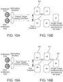
- the processor calculates the location on the screens 804. If the 2 eyes of the patient are parallel, the 2 images for both eyes should be displayed exactly on the same location on the monitor. Each eye will perceive each identical & relevant part of the picture exactly on the fovea. The brain will combine these 2 images into one 3D image, see Figs. 15A, 15B . For clarity, the images on the figures are shown as a simple cross to emphasize the algorithm. The images can be parallel to simulate a far view as shown in Figs. 15A, 15B or can be shifted inwards to simulate near view as shown in Figs. 16A, 16B .
- Our device will determine the relative gazing direction of each eye. Let's assume again that the 2 eyes of the patient are not parallel, e.g. the patient suffers from strabismus. We shift the image for the strabismic eye in such a way that its interest area will be projected exactly on the fovea. The non strabismic eye will also see the interest location of the image exactly on the fovea. The total perceived image will be combined by the brain and produce a single, normal 3D image, see Figs. 18A, 18B .
- the apparatus will compensate for any type of eyes' deviation, either concomitant (non-paralytic) or incomitant (paralytic) strabismus.
- the processor will display the 2 processed images on the proper location on the display and the process will continue during the whole training session. 805
- Fig. 12A shows the method of operation of the test or treatment, with the amblyopic eye 14, nonamblyopic eye 15, 3D glasses 2, and the distant target gazing direction 723.
- Fig. 12B shows the different sized images 301, 302 which would be presented on each eye's retina without an external intervention/ correction. This effect is due to a patient's vision problem (a difference in eyes magnification, or zoom). Such different sized images may prevent the images to be combined in the brain.
- One goal of our invention is to correct the image presented to one eye, by enlarging or reducing the image as required, to obtain the same sized images 311, 312 in both eyes. The same size images will be combined in the brain into one image 321 (a tri-dimensional image if the original images 301, 302 pertain in a 3D object).
- Figs. 12C, 12D show the different sized images which would be presented on each eye's retina without an external intervention/ correction.
- Fig. 14A shows a non-claimed method of treatment using a moving object 305 which is presented to the amblyopic eye
- Fig. 14B shows the image presented to the nonamblyopic eye, which does not include a moving object.
- Figs. 15A, 15B show non strabismic eyes, far vision.
- Fig. 15B shows the images 301, 302 which would be presented on each eye's retina without an external intervention/ correction.
- the images are correctly of the same size and appear at the same location on the retina, thus correction is not required.
- Figs. 16A, 16B show non strabismic eyes, near vision.
- Fig. 16B shows the images 301, 302 which would be presented on each eye's retina without an external intervention/ correction.
- the images are not presented on the same location for both eyes, therefore there is a problem in combining them in the brain.
- One goal of our invention is to correct the images presented to one eye or both eyes, by changing the location of the images presented on the retina, so identical or similar images appear on the same location as shown with corrected images 311, 312 in both eyes.
- the same size images will be correctly combined in the brain into one image 321 (a tri-dimensional image if the original images 301, 302 pertain in a 3D object).
- Figs. 17A, 17B show Strabismic Eyes, Far Vision, Image Location Not Corrected.
- Fig. 17B shows the images 301, 302 which would be presented on each eye's retina without an external intervention/ correction.
- the images would be presented on the same location for both eyes, but the eyes point in different directions, therefore the perceived images 311, 312 are not co-located, and there is a problem in combining them in the brain, as shown in image 321.
- Figs. 18A, 18B show Strabismic Eyes, Far Vision, Corrected Image Location.
- One goal of our invention is to correct the images presented to one eye or both eyes, by changing the location of the images presented on the retina 301 and 302, so identical or similar images appear on the same location as shown with corrected images 311, 312 in both eyes.
- the same size images will be correctly combined in the brain into one image 321 (a tri-dimensional image if the original images 301, 302 pertain in a 3D object).
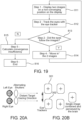
- Fig. 19 is the flowchart showing the basic process of diagnosis, comprising:
- the processor obtains the required images from the training program and display them on the display in the initial, non-converging locations.
- the image source can be either stationary pictures, video, games, normal scenery etc. See Fig. 20 .
- the 2 eyes are parallel as in the case the image is far away. 811
- the eye trackers track the eyes and inform the processor whether the eyes tracked the image. 812
- the images will "move in”, for example by additional 1 degree. 814 . See also Figs. 21A, 21B .
- the processor will calculate the convergence insufficiency angle according to the last angle. If the eyes converged at least as the required convergence for the specific target distance then convergence insufficiency could be ruled out. 815
- Figs. 20A, 20B show Initial Image Location - Far Vision.
- Fig. 20B shows the images 301, 302 which would be presented on each eye's retina without an external intervention/ correction.
- the images are correctly of the same size and appear at the same location on the retina, thus correction is not required.
- Figs. 21A, 21B show Image Location - After "moving in”.
- One goal of our invention is to correct the images presented to one eye or both eyes, by changing the location of the images presented on the retina 301 and 302, so identical or similar images appear on the same location as shown with corrected images 311, 312 in both eyes.
- the same size images will be correctly combined in the brain into one image 321 .
- Figs. 22A, 22B show Image Location - Insufficient-Converging Eyes.
- Fig. 22B shows the images 301, 302 which would be presented on each eye's retina without an external intervention/ correction.
- the images are not co-located, therefore the perceived images 311, 312 are not co-located, and there is a problem in combining them in the brain, as shown in image 321.
- the exercise may be continued even beyond optimal convergence to achieve a better training for the child.
Description
- The present invention relates to visual impairments caused by eye and neural diseases and more specifically to an apparatus for screening, treatment, monitoring and assessment of visual impairments.
-
Hess et al., US 8,057,036 - Binocular vision assessment and/or therapy. -
Evans et al., US 20130258463 - System, method, and apparatus for enhancing stereoscopic images. -
Vendel et al., US 8,770,750 - Apparatus and method for establishing and/or improving binocular vision. -
Avni et al., WO 2014/041545 - Systems and methods for treating amblyopia by visual stimulation of the brain. -
Fateh, US 8,820,930 - System, method and apparatus for amblyopia and ocular deviation correction. -
Foss, WO 2015/145111 - Apparatus and methods for the treatment of ocular disorders. It discloses an apparatus for treatment of amblyopia, comprising: image presentation means adapted to display a first image to the non-amblyopic eye and a second image to the amblyopic eye to be perceived as coincidental; eye-tracking means adapted to monitor the direction of gaze of the non-amblyopic eye and the amblyopic eye; means for creating a region of degradation at the point of fixation of the first image while the second image has no degradation; means for evaluating scotoma based on the time when the eye tracking means detect the amblyopic eye to take up fixation. -
Hay et al., US 2001/0050754 - Apparatus and method for treatment of amblyopia. - Amblyopia is a developmental disorder of spatial vision usually associated with the presence of strabismus, anisometropia or vision form deprivation early in life. It affects visual acuity, contrast sensitivity and depth perception and, if not timely treated properly, might result permanent reduction of visual capacity of the amblyopic eye. Amblyopia is clinically important because it prevents the visual apparatus from developing normally and it is the most frequent cause of vision loss in infants and young children; About 4% of children and 2% of adults suffer from amblyopia.
- In healthy individuals, two slightly different images are transferred from both eyes to the brain which fuses these two images into a composite, single, 3-dimensional image.
- Sometimes, however, the image arriving from one eye significantly differs from that arriving from the other eye. This can be caused by a variety of factors, such as the eyes not being parallel (strabismus), one eye being more far or short sighted than the other (anisometropia), or diseases that create abnormal images in an eye of a child (such as a cataract or other media opacity). Such conditions in adults lead to double or blurry vision. However, the child's brain can avoid such disturbing sensation by disregarding the image from one eye. If this condition is not successfully treated during childhood, the person will become permanently amblyopic, i.e. the brain ignores the image from the amblyopic eye and this eye will have poorer vision then the other one. Normally there is no spontaneous improvement in the vision of the amblyopic eye and in about half of the cases there is deterioration after diagnosis.
- Stereoscopic vision will not develop properly or not at all in amblyopic people, even if successfully treated on time; they are incapable of precise stereoscopic vision and consequently of depth perception. Amblyopic people are thus limited in their career choice in addition to being worried about having only one fully functional eye, more liable to lose the seeing eye and suffering more commonly from a variety of psychological conditions.
- It was found in a survey of adult amblyopes (without strabismus) that they felt that the diseases interfered with school (52%), interfered with their work (48%), affected their lifestyle (50%), affected their sport participation (40%) and influenced their career choice (36%). These patients were found to have a significantly greater degree than normal of somatization, obsessive - compulsive behavior, excessive interpersonal sensitivity and anxiety.
- Convergence insufficiency is a common near vision problem that interferes with a person's ability to see, read, learn, and work at near distances.
- Signs and symptoms occur while the child is reading or engaged in other near field activities and may include eyestrain, headaches, difficulty reading, double vision, difficulty concentrating, squinting or closing one eye.
- Children with CI have more symptoms and show worse attention when reading than children without CI. This might make parents or teachers suspect that a child has a learning disability, instead of an eye disorder.
- The problem exists in adults as well, especially the people who spend a considerable time looking at near objects such as computer screens.
- Many other eyes' deficiencies exist such as visual acuity decrements, strabismus (either tropia and phoria), stereopsis acuity, color blindness and various eye dynamics ailments. They effect many children and if not treated early in life, become incurable.
- Amblyopia is treated by forcing the use of the amblyopic eye by preventing the non-amblyopic eye from seeing or reducing the quality of vision in that eye. Treatment of amblyopia is effective only in children up to the age of nine or younger. There are several ways, or combinations thereof, to perform the treatment detailed below.
- Occluding the dominant eye by patching, electronic shutters, blurred lens, etc.
- Occlusion of the dominant eye (good eye) is a long-established method and produces positive results in many cases, but only when there is a good compliance with the treatment. However, patching has many drawbacks, mainly the impaired visual functions engendered by covering the better-seeing eye in children, as well as the social and emotional problems related to wearing an unsightly eye-patch. As a result of all these factors, compliance with eye patching is limited and many children reach the critical age of nine with reduced vision in the affected eye that is considered to be incurable.
- Furthermore, since the patching method stimulate alternately only one eye at a time, the stereopsis process in the visual cortex is not challenged and therefore deteriorates or no developing at the first place, disabling the patient from 3 dimension perception even if good visual acuity is attained in both eyes separately.
- In addition, a child suffering from strabismic amblyopia will be referred to a strabismus surgery. However, since eyes are not used to work together, even after the surgery the tendency of the eyes to move synchronously is weak, and the eyes might misalign again even if the surgery was a successful one and patching therapy was practiced prior to the surgery.
- Atropine is instilled into the non-amblyopic eye and causes pupillary dilation and reduced accommodation subsequently forcing the amblyopic eye to be used for near-vision tasks. This treatment can cause reverse amblyopia. Further disadvantages are the pupillary dilatation in the treated eye causing light sensitivity, lack of development of stereopsis and irregular compliance.
- This method is used for corrections of anisometropic amblyopia by equalizing the size and sharpness of the images on both eyes. This therapy can't be used to treat strabismic amblyopia and is effective only if undertaken in time. The latter is problematic, since, unlike strabismus, there are no apparent symptoms of the condition.
- This method was introduced in recent years and provide different images to both eyes, introducing a better image quality for the amblyopic eye while providing a degraded image for the fellow eye.
- The pictures are presented either on 3D PC monitors or on head-mounted displays.
- However, this method does not ensure the simultaneous and accurate foveal stimulation for strabismic patient, especially when the deviation angle between the two eyes is not constant for different gazing angles. Furthermore, it's nearly impossible to calibrate the apparatus to compensate for heterophoria.
- Perceptual learning - a process by which the ability of sensory apparatus to respond to stimuli is improved through experience. Perceptual learning occurs through sensory interaction with the environment as well as through practice in performing specific sensory tasks. The changes that take place in sensory and perceptual apparatuss as a result of perceptual learning occur at the levels of behavior and physiology. Perceptual learning involves relatively long-lasting changes to an organism's perceptual apparatus that improve its ability to respond to its environment.
- Studies showed that perceptual learning provide an important method for treating amblyopia. Practicing a visual task results in a long-lasting improvement in performance in an amblyopic eye. The improvement is generally strongest for the trained eye, task, stimulus and orientation, but appears to have a broader spatial frequency bandwidth than in normal vision. Importantly, practicing on a variety of different tasks and stimuli seems to transfer to improve visual acuity.
- One major drawback of the methods above is that the eyes are stimulated one at a time thus providing the brain with monocular images and preventing to exercise the stereopsis process performed in the visual cortex of the brain. Thus, depth perception is degenerated.
- The success rate in childhood amblyopia treatment is about 50% [reaching vision better than 6/9 (20/30)] and is better in anisometropic than in strabismic amblyopia. This is the only amblyopia treatment which is at least partially successful in adults. However, it requires long duration of repeated perceptual training and thus is limited by low compliance which causes it not to become a regular amblyopia treatment.
- Treatment of the amblyopia should always be combined with treatment of its cause, i.e. surgery for the strabismus, optical correction for the anisometropia and removal of the causes of unequal vision. Even when successful treatment took place during the critical period in children under nine years of age, the results are not permanent and about half of the patients deteriorate and may require maintenance therapy. Furthermore, deterioration of the surgically corrected strabismus often occurs as there is no stereoscopic vision which helps to keep the optical axes aligned.
- As a consequence of the relative ineffectiveness of the present-day treatment of childhood amblyopia and the difficulty of diagnosing the disease when it is still treatable, 2% to 4% of the adult population in all countries is amblyopic.
- Amblyopia is considered untreatable in people older than 9 years. However, recent studies suggest that adult amblyopia is treatable - as can be learned from the success of perceptual learning, proving that the neural pathways, presumed lost for the amblyopic eye can be used for treatment in adults. This modality involves continuous tedious ocular exercises and is therefore rather impractical.
- Treatments range from passive prism lenses to active office-based vision therapy. Scientific research by the National Eye Institute has proven that office-based vision therapy is the most successful treatment.
- Home-based pencil pushups therapy appears to be the most commonly prescribed treatment, but scientific studies have shown that this treatment is ineffective.
- Even though these methods are quite simple, the requirement of occasional visit at the doctor's office is cumbersome while the home base pencil pushups therapy is boring for the child and have a low compliance.
- In addition, in both methods, real time monitoring of the progress of the child to track the stimulus does not exist, therefore feedback for the therapist and parents is unavailable nor a real time feedback for the child that might stimulate him to improve his exercises.
- Current approaches are performed by specialists - either ophthalmologists, orthoptists or optometrists and require procedures that are time consuming and expensive.
- Visual acuity, strabismus and heterophoria, stereopsis depth and eyes' dynamic tests are standard and routine tests. However, they require patient cooperation which is difficult or even impossible to perform on toddlers.
- Those tests are important factors in providing the ability to detect amblyopia (and other malfunctions of the eye) and to assess the progress in the amblyopia treatment.
- These and other problems in prior art methods and apparatu for Screening, Diagnosing, Assessing, Monitoring and Treating Eye Diseases and Visual Impairments Using Eye Tracking are addressed with the present invention.
- The present invention relates to an apparatus for screening, treatment, monitoring and/or assessment of visual impairments, comprising:
- electronic means for simultaneously applying two separate processing methods to images presented to an amblyopic eye and a non-amblyopic eye of a patient wherein, the electronic means comprise image generating means, digital image processing means, eye tracker means for measuring a direction of the patient eyes' line of sight, and display means for presenting images to both of the patient's eyes,
the two separate processing methods being:- a first processing method being applied to the non-amblyopic eye, and
- a second processing method being applied to the amblyopic eye,
- wherein the first processing method presents a first image comprising an area with a controlled measure of image degradation to the non-amblyopic eye, using the display means, wherein the second processing method includes presenting a second image to the amblyopic eye by changing the first image so as to present identical or as similar as possible first and second images to the two eyes, to allow combining the images in the brain, and wherein the second processing method is responsive to a direction of a line of sight of the amblyopic eye measured by the eye tracker means,
- characterized in that:
the location of the degraded area is moved on the screen responsive to a direction of the line of sight of the non-amblyopic eye, measured by the eye tracker means. - In some embodiments, the second processing method includes a movement of the image vertically and/or horizontally, changing the magnification of the image (zoom in or zoom out), and/or rotation of the image.
- In some embodiments, the second processing method further includes correcting defects of the amblyopic eye so the brain will perceive identical, or as close to identical as possible, images from the two eyes, allowing the brain to combine the two images into one obj ect.
- In some embodiments, the apparatus is configured for compensating for changes of strabismus angles with different gaze directions based on live eye tracking data.
- In some embodiments, changing the image of the second processing method comprises correcting defects of the amblyopic eye by processing the image presented thereto.
- In some embodiments, changing the image may include a movement of the image vertically and/or horizontally, changing the magnification of the image and/or rotation of the image.
- In some embodiments, changing the image of the second processing method comprises stimulating the amblyopic eye with: a clear and sharp image or a high contrast image.
- In some embodiments, the area with a controlled measure of image degradation is not uniform, optionally wherein in the area with a controlled measure of image degradation, the degradation is stronger in the center of the area and is gradually reduced towards the edges of the area, to provide a smooth transition.
- In some embodiments, the second processing method includes changing the image so as to present real 3D disparity so the patient perceives the depth of each object in space.
- In some embodiments, the first processing method and the second processing method comprise applying different complementary blobs of image to each eye, optionally wherein the blobs are of different shapes and vary with time.
- In some embodiments, the first processing method and the second processing method are such that only the image presented to the amblyopic eye includes a moving object (305).
- In some embodiments, the first processing method and the second processing method are applied to true 3D images.
- This description may includes disclosure that does not fall within the scope of the claims but is useful for understanding the invention.
- The main features and benefits of the present invention are:
- 1. An apparatus for measuring and/or treating a vision-related disease, using two separateprocessing methods being simultaneously applied to the patient's eyes.
- The image presented to each of patient's two eyes undergoes a different processing:
- a. For the non-amblyopic eye, the processing includes an area with a controlled measure of image degradation, to cause the patient to rely more on the other, weaker eye; furthermore, the location of the degraded area is moved on the screen responsive to the measured direction of the line of sight of the non-amblyopic eye;
- b. For the amblyopic eye, the processing includes changing the image so as to present identical, real 3D disparity or as similar as possible images to the two eyes, to allow combining the images in the brain.
- Processing may include a movement of the image vertically and/or horizontally, changing the magnification of the image (zoom in or zoom out), and/or rotation of the image.
- The processing is responsive to the measured direction of the line of sight of the amblyopic eye-
- That is, as the line of sight moves vertically and/or horizontally and/or torsionally, so the presented image on the screen is moved as well.
- 2. "On the go" real time treatment. The patient can receive treatment as he works, walk, during recreation, etc. The patient wears goggles with means for capturing real-time images, a processor for processing the image to one eye or both according to predefined settings adapted to that patient's ilness, and display means for presenting the processed image(s) to the patient's eye(s).
- This embodiment may save patient's time, and is easier to perform. Rather than visiting a clinic, waiting and receiving treatment, the patient receives treatment while he/she is doing other tasks.
- 3. Using true tri-dimensional (3D) images for measurement and treatment. True 3D images best stimulate the brain to combine the images, so the patient perceives the depth of each applied to an non-amblyopic eye (the eye with the better vision), and a second processing method being applied to an amblyopic eye (the weaker eye, or the impaired eye).
- The electronic means comprise images generating means, digital image processing means, eye tracker means for measuring a direction of the patient eyes' line of sight, and display means for presenting images to at least one of the patient's eyes.
- In some embodiments, the apparatus is stationary and is based on a desktop or a laptop personal computer (PC) .
- In some embodiments, the apparatus is portable and is based on a tablet or smart phone.
- In some embodiments, the apparatus is portable and is based on wearable goggles, wherein the display means comprise micro-displays mounted on the goggles, and further including a digital processor for control and images processing.
- The first processing method creates an area with a controlled measure of image degradation.
- In some embodiments, the the area with image degradation is so located on the display as to be presented on a fovea of the non-amblyopic eye.
- In some embodiments, the area with image degradation is so located on the display as to be presented on a macula of the non-amblyopic eye.
- In some embodiments, the apparatus further includes means for using the measured direction of sight of the non-amblyopic eye for presenting the area with image degradation on the fovea or the macula of the non-amblyopic eye.
- In some embodiments, the second processing method includes changing the image so as to present identical, real 3D disparity and as similar as possible images to the two eyes, to allow combining the images in the brain. In some such embodiments, the second processing method includes a movement of the image vertically and/or horizontally, changing the magnification of the image (zoom in or zoom out), and/or rotation of the image.
- The second processing method is responsive to a measured direction of a line of sight of the amblyopic eye. In some embodiments, the apparatus further usies the eye tracker means for measuring the the line of sight of the amblyopic eye.
- One of the goals of the apparatus is to treat amblyopia by preserving and improving the visual acuity of the amblyopic eye while preserving and enhancing the depth perception of the patient.
-
- Each of the presented embodiments examples work for all described tasks
- The description provides examples of stationary and portable apparatuss
- Adjustable for near or far vision treatment by adjusting properly the accommodation and convergence parameters
- Eye trackers will track the eyes and verify whether the eyes track the presented object
-
- Providing dichoptic images (different images to each eye) either stationary, or dynamic in the form of movies, games, animations etc. thus exercising the stereopsis process in the brain. The 2 images can be identical or have disparity properties for providing real depth sensation for better enhancement of the stereopsis process, and strabismus compensation.
- In case of strabismic amblyopia (most difficult type of amblyopia to overcome) the suggested apparatus would be the only solution that enables a binocular, clear fused image on the retinas even if strabismus angles change with different gaze directions. This compensation will be implemented by the real-time image disparity compensation based on the live eye tracking data.
- The nature of the images will be different in such a way as to challenge the brain to prefer the use the amblyopic eye while stimulating also the fellow eye (even with reduced or partial image quality) thus exercising the related brain pathways in charge of the visual information received from the amblyopic eye, and encouraging the stereopsis process in the visual cortex of the brain.
- Inherent capability for treating also anisometropic amblyopia by providing different sized images to each eye.
- A single or multiple eye trackers (an existing technology) will ensure the coherence projection of the 2 images on the fovea regions of the 2 eyes according to the instantaneous gazing direction for all conditions of asymmetric eye movements, including torsional deviation.
- For portable goggles, images can be provided by one or two scene cameras allowing "on the go" treatments.
- Ability to train vision in both near field and far field.
- Automatic progress monitoring and assessment using the eye tracking feedback.
-
- Providing a single image or dichoptic images (different images to each eye) either stationary, or dynamic in the form of movies, games, animations etc. The 2 images can coincide or have disparity properties for providing real depth sensation for better enhancement of the stereopsis process and strabismus compensation.
- The 2 images are automatically moving towards each other and even to opposite sides of the screen so as to challenge the eyes of the patient to converge.
- The eye trackers will verify whether the eyes are properly tracking the inward moving targets.
- This exercise will be presented to the child in a gradual manner and the progress will be monitored, evaluated and changed according the progress and training program thus providing valuable feedback to the practitioner and parents and allows for a bio-feedback for the child.
-
- Providing a single image or dichoptic images (different images to each eye) either stationary, or dynamic in the form of movies, games, animations etc.
- The 2 images can coincide or may have disparity properties for providing real depth sensation for better enhancement of the stereopsis process and strabismus compensation
- The single or separate 2 images include dynamic stimulus at predefined speeds and paths as to train and monitor the ocular muscles to work separately and as a team.
- The eye trackers will verify whether the eyes are properly tracking the stimulus.
- This exercise will be presented to the child in a gradual manner and the progress will be monitored, evaluated and changed according the progress and training program thus providing valuable feedback to the practitioner and parents and allows for a bio-feedback for the child.
- The apparatus measures, during normal training various parameters and asseses various visual performances of the eyes.
- Important benefits: All the tests can be conducted even on pre-school children, since these tests do not require any voluntary feedback from the child or cooperation therewith. Following are examples of tests that can be performed continuously or periodically:
- Visual acuity and contrast sensitivity
- Strabismus angles and extent of heterophoria
- Convergence deficiency
- Eye movements: saccades speeds, trajectory and reaction time
- Depth perception and stereopsis quality
- Pupil diameter and responses
- Based on above, the apparatus analyzes the measured data, assesses the progress based on comparison with past patient data or with a standard model and:
- Changes the treatment program
- Provides alerts and reports to the doctor, patient or patient's relatives
- Provides a bio-feedback to the child
- For screening, the apparatus performs the same measurements as for monitoring and assessment, compares it to standard data for reporting of possible problems that requires more thorough examination by a specialist.
- Since screening requires a less accurate level of results, a higher threshold might be used with a faster test sequence and lower cost apparatus.
- Since all the above testing are automatic and fast, the screening procedures can be performed by a technician, school nurse and others. The tests do not necessary require a specialist such as an ophthalmologist or optometrist.
- Amblyopia condition, which must be detected as early as possible and is the most common and dangerous problems in young, even preverbal children, will thus be easily detected (with all or some of the tests). Appropriate referral to the specialist will be generated and reduce the existing high "false positive" rate, which have a significant burden on the eye care apparatus, and reduce the "false negative" rate that fails to detect many children and causes them incurable, severe eye problems.
- As detailed in the present disclosure, the invention overcomes the disadvantages of the existing treatments methods and devices, is easily performed, and is attractive to the children.
- The monitoring, assessment and screening, need minimal child cooperation and can be performed in a matter of minutes or even seconds.
- Further purposes and benefits of the current invention will become apparent to persons skilled in the art upon reading the present disclosure and the related drawings.
- Embodiments of the invention are disclosed hereinafter with reference to the drawings, in which:
-
Fig. 1 shows a Stationary apparatus, a General View. -
Fig. 2 shows a Stationary apparatus, a Block Diagram. -
Fig. 3 shows a Portable apparatus, Tablet Based - a General View. -
Fig. 4 shows a Portable Binocular apparatus - a General View. -
Fig. 5 shows a Portable Monocular Apparatus - a General View. -
Figs. 6A-6D shows a Portable Apparatus, Goggles Cross Sectional view. -
Fig. 7 shows a Portable Apparatus, Binocular, a Block Diagram. -
Fig. 8 shows a Portable Apparatus, Monocular, a Block Diagram. -
Fig. 9 shows a Method: Amblyopia Treatment Main Process. -
Fig. 10A shows the high contrast image presented to the amblyopic eye, andFig. 10B shows the low contrast image presented to the fellow (better, stronger vision) eye. -
Fig. 11A shows the high contrast image presented to the amblyopic eye, andFig. 11B shows the "no image" presented to the fellow (better, stronger vision) eye. -
Fig. 12A shows the method of operation of the test or treatment. -
Fig. 12B shows the different sized images which would be presented on each eye's retina without an external intervention/ correction. -
Figs. 12C, 12D show the different sized images which would be presented on each eye's retina without an external intervention/ correction. -
Figs. 13A, 13B show a treatment method using different blobs, of complementary images, presented to each eye. -
Fig. 14A shows a method of treatment using a moving object andFig. 14B shows the image presented to the nonamblyopic eye, which does not include a moving object. -
Figs. 15A, 15B show non strabismic eyes, far vision. -
Figs. 16A, 16B show non strabismic eyes, near vision. -
Figs. 17A, 17B show Strabismic Eyes, Far Vision, Image Location Not Corrected. -
Figs. 18A, 18B show Strabismic Eyes, Far Vision, Corrected Image Location. -
Fig. 19 shows a Method for convergence insufficiency diagnosis, main process. -
Figs. 20A, 20B show Initial Image Location - Far Vision. -
Figs. 21A, 21B show Image Location - After "moving in". -
Figs. 22A, 22B show Image Location - Insufficient-Converging Eyes. - The current invention will now be described by way of example and with reference to the accompanying drawings.
-
- a. The 3D monitor and glasses can be of any kind - e.g. passive, alternating, polarized etc.
- b. Monitor = display = screen (Stationary apparatus - one 3D display; Portable apparatus - one or two micro-displays)
- c. 3D= three-dimensional
- d. Near eye display = micro display
- e. Fellow eye = non amblyopic eye (the better, stronger eye).
- The image presented to each of patient's two eyes undergoes a different processing:
- a. For the non-amblyopic eye, the processing includes an area with a controlled measure of image degradation, to cause the patient to rely more on the other, weaker eye; furthermore, the location of the degraded area is moved on the screen responsive to the measured direction of the line of sight of the non-amblyopic eye;
- b. For the amblyopic eye, the processing includes changing the image so as to present identical or as similar as possible images to the two eyes, to allow combining the images in the brain.
- Processing may include a movement of the image vertically and/or horizontally, changing the magnification of the image (zoom in or zoom out), and/or rotation of the image.
- The processing is responsive to the measured direction of the line of sight of the amblyopic eye-
- That is, as the line of sight moves vertically and/or horizontally, so the presented image on the screen is moved as well.
- Gradual image degradation: for the non-amblyopic eye, the measure of image degradation needs not be uniform in the area with image degradation; preferably, the degradation is stronger in the center of that area, and is gradually reduced toward the edges of the area, to provide a smooth transition.
- The patient can receive treatment as he /she works, during recreation, etc. The patient wears goggles with means for capturing real-time images, a processor for processing the image to one eye or both according to predefined settings adapted to that patient's ilness, and display means for presenting the processed image(s) to the patient's eye(s). This embodiment may save patient's time, and is easier to perform. Rather than visiting a clinic, waiting and receiving treatment, the patient receives treatment while he/she is doing other tasks.
- True 3D images best stimulate the brain to combine the images, so the patient perceives the depth of each object in space- an essential benefit, which people with normal
- The method includes:
- a. defining a starting point, wherein differences between a patient's eyes are completely, or as closely as practically possible, corrected, to enable two identical or similar images to be transferred to the brain from the patient's eyes;
- b. defining an ending point, wherein there is no correction applied to any of the patient's eyes;
- c. defining a screening, treatment, monitoring and/or assessment plan, for initially applying correction to images according to the starting point, then gradually reducing the correction, at a controlled and predetermined rate, towards the ending point; and
- d. applying the plan to images presented to the patient's eyes, while monitoring patient's performance;
- e. adjusting the rate of change of the correction responsive to results of monitoring the patient's performance;
- f. defining a range of desired rate of improvement with minima and maxima, during monitoring comparing actual patient's performance with the desired rate of improvement, and issuing a report or a warning if the actual performance exceeds the range of desired rate of improvement.
- The apparatus in the present invention is modular and flexible; it is software-controlled, to achieve a very powerful and useful apparatus for Screening, Diagnosing, Assessing, Monitoring and Treating Eye Diseases and Visual Impairments.
-
- 1. It is essential to distinguish between
- (a) Using true tri-dimensional (3D) images for measurement and treatment, on the one hand, and
- (b) 3D display devices, such as 3D glasses, etc.
- The feature (a) is an essential part of the present invention, and relates to 3D images creation, separate processing for each eye and separate display to each eye;
Whereas (b) relates to prior art equipment for presenting separate images to each eye. - The present invention uses 3D devices in (b) to present a different, separate image to each eye; but this is just one component of the apparatus and method presented in (a).
- 2. Contemporary digital processors offer means for powerful image processing, in small packages and at low cost. This facilitates making a portable, "On-the-go" apparatus.
- One example of such a processor is the 32 bit PIC32MZ Family of High performance microcontroller with Floating point Unit (FPU) and an advanced peripheral set, manufactured by Microchip Technology Inc.
- We will describe here examples of 3 embodiments, all based on similar principles and sub-assemblies:
- Stationary Apparatus based on PC, laptop etc., for home or office use;
- Portable apparatus based on tablet, smart phone etc. for home, office or screening;
- Portable apparatus based on goggles with micro-displays for home, office or "on the go" use.
- In all the embodiments, either stationary or portable, corrective lenses, if required, might be added. In the portable apparatus based on goggles, a special fitting for the addition of corrective lenses might be added to the goggles frame or directly integrated into the provided eye pieces' lenses.
- In addition, the images will be provided separately for both eyes in such accommodation/convergence properties as required for near or far vision. The principle of operation is as described in our international patent application No.
PCT/IL2016/050232 - In addition, a microphone can be added with appropriate voice recognition software for getting patient response to various stimuli, measurements of reading speeds etc. The microphone is depicted only in
Fig. 2 but similarly can be added to all embodiments. -
Fig. 1 shows a Stationary Apparatus, comprising: 3D glasses 2 (alternating shutter glasses in this example), a 3D display or monitor 3, aremote eye tracker 4 located near the display or a close-by eye tracker mounted on the glasses frame, and a personal computer (PC) or adigital processor 5 . - Also shown are a
patient 1 and twodichoptic images 31. - The apparatus block diagram is depicted in
Fig. 2 , and includes: A personal computer (PC) or adigital processor 3D glasses 2 with 3D glasses controls 21, control inputs (i.e. keyboard, mouse, tablet, etc.) 51, amicrophone 52,remote eye tracker 3D display 3. - Also shown are the
eye tracker data 41, display signals 32, patient'sleft eye 13 andright eye 12. - The
processor 5 controls the 3D glasses 2 (if required) and sends the required and processed two dichoptic images (either stationary pictures, video, games etc.) to the3D display 3. In addition, the processor receives the eyes' gazing direction from theeye tracker 4 and all required controls from the input devices such as the keyboard, mouse etc. - Instead of a PC, the apparatus can use a tablet (such as an iPad) or a smart phone with an eye tracker. The eye tracker can be replaced by the integrated tablet/phone camera to serve as an eye tracker.
-
Fig. 3 shows a Portable Apparatus, Tablet Based. The apparatus includes3D glasses 2, A tablet with afront view 61 andrear view 62, integratedcamera 63 andremote eye tracker 4. - Also shown is a
patient 1. - The goggles embodiment comprises the following parts, see
Fig. 4 : - * Two eye trackers, one for each eye, located near the eyes; the right eye near
tracker 45 and left eye neartracker 46. - * One or more micro-displays (with appropriate optics), one for each eye (in case of 2 micro displays), located near the eyes (this embodiment does not require a 3D display and 3D glasses); these are the right
near eye display 34 and leftnear eye display 35. - * The goggles might employ one or two
scene cameras - * Ocular optics
- * Portable control box/
processor 6. - The above detailed parts (possibly with the exclusion of the processor 6) may be mounted on a portable binocular or
monocular frame 39 - A monocular apparatus includes one micro display, one scene camera and one ocular optics, see
Fig. 5 . Shown are the portable binocular ormonocular frame 39 andright scene camera 71. -
Figs. 6A-6D depict a cross-section of the goggles. The eye trackers 45, 46 are located below the eyes to eliminate obstruction of the image. Theocular lens 38 allows the eyes to focus on the micro-displays 34, 35 in order to project the image at the required distance according to the prescribed training program. - The ocular sub-assembly may include corrective optics if required by the patient.
- The apparatus includes
right scene camera 71, leftscene camera 72, right neareye display 34,left neareye display 35, right eye neartracker 45, left eye neartracker 46 andeyepiece lens 38. Also shown are patient'sright eye 12 and lefteye 13. - The processor sends the required two dichoptic images (either stationary pictures, video, games, etc.) to the micro-displays - see a block diagram for binocular apparatus in
Fig. 7 and a monocular apparatusFig. 8 . - The Control Box/Processor is not shown on these figures. In addition, the processor receives the eyes' gazing direction from the eye trackers and all required controls from the input devices such as the keyboard or control buttons on the goggles etc.
- If required, the scene cameras capture the scene in front of the patient, processed accordingly by the processor to be displayed on the micro displays.
-
Fig. 7 shows a Portable Apparatus, Binocular, a Block Diagram including:eyepiece lens 38, near eye displays 34, 35 , eye neartrackers scene cameras amblyopic eye 14 andnonamblyopic eye 15, an object orscenery 19, andvirtual views -
Fig. 8 shows a Portable Apparatus, Monocular, a Block Diagram including:eyepiece lens 38, neareye display 35, eye neartracker 45, eye neartracker 46 andscene camera 72. Also shown are patient'samblyopic eye 14 andnonamblyopic eye 15, an object orscenery 19, andvirtual view 721 from camera to object. - The main requirement for amblyopia treatment is to prevent the amblyopic eye/brain apparatus from deterioration causing a permanent & incurable vision decrement. This must be accompanied (not the subject of the present invention) and in parallel, by addressing the cause for amblyopia. The processes enforce the brain to use the amblyopic eye.
- In our apparatus, we enforce the brain to use the amblyopic eye but we do provide appropriate stimulation for the non-amblyopic eye as well, in order to train the stereopsis process and preserve the binocular vision and depth perception.
- In order to overcome the problems of existing treatment options as mentioned above, our apparatus will work as follows:
- The professional (ophthalmologist or optometrist) will determine the required type of stimulation. It can be either stationary pictures, video, games, normal scenery etc. Following are few examples:
- o Stimulating only the amblyopic eye for a certain percentage of time. The fellow eye does not receive any stimulation
- o Stimulating the amblyopic eye with a clear and sharp image while providing the fellow eye with a blur image either by degeneration of sharpness, intensity, details etc.
- o Providing different segments of the image to each eye separately
- Providing different locations of the right/left images in order to compensate for Strabismus in case of strabismic amblyopia
- The images might be provided separately for both eyes in such accommodation/convergence properties as required for creating virtual near or far image. The principle of operation is as described in our international patent application No.
PCT/IL2016/050232 - The eyes tracker ensures that the stimulation center remains on the fovea region no matter in which direction each eye is looking at.
- The method will provide treatment while the child is playing PC games, watching video etc.
- The main requirement for convergence deficiency diagnosis is to provide variable convergent images, beginning with relatively apart images which does not require the eyes to converge and gradually moving in the 2 images until the eye trackers will inform the processor that the eyes stopped converging.
- The main requirement for convergence deficiency treatment is to provide variable convergent images, beginning with relatively apart images which does not require the eyes to converge and gradually moving in the 2 images to train them to converge.
- In order to overcome the problems of existing treatment options as mentioned above, our apparatus will work as follows:
- The professional (ophthalmologist or optometrist) will determine the required type of stimulation. It can be either stationary pictures, video, games, normal scenery etc. Following are few examples:
- The images will be provided separately for both eyes in such convergence properties as required for creating virtual near or far image. The principle of operation is as described in our international patent application No.
PCT/IL2016/050232 - The eyes tracker ensures that the stimulation center remains on the fovea region no matter to which direction each eye is looking at.
- The same treatment can be performed for patient suffering from heterophoria.
- The process implemented in the various embodiments are similar. The description hereinafter is united and the differences are mentioned.
-
Fig. 9 is the flowchart showing the basic process of treatment, including: - The processor obtains the required images from the training program. The image source can be either stationary pictures, video, games, normal scenery etc. 801
- The processor performs required image processing on the images. Following are some examples (There can be many more ways) 802:
- * High contrast for amblyopic eye and low contrast for fellow eye (see
Figs. 10A, 10B ). The contrast differences can vary with time (duty cycle), pictures quality, colors etc. This will encourage the brain to prefer to get more information from the amblyopic eye. -
Fig. 10A shows the high contrast image presented to the amblyopic eye, andFig. 10B shows the low contrast image presented to the fellow (better, stronger vision) eye. - * No image for the fellow eye (see
Figs. 11A, 11B ). The absence of image can vary with time (various duty cycles). This method is actually comparable to the existing eye patching method used currently. -
Fig. 11A shows the high contrast image presented to the amblyopic eye, andFig. 11B shows the "no image" presented to the fellow (better, stronger vision) eye. - * Provide different sized images to each eye for cases of for treating anisometropic amblyopia in such a way that the 2 images will be perceived by the patient as identical size thus being able to be combined (see
Figs. 12A- 12D ) by the brain. - * Apply different complementary blobs of image to each eye (see
Figs. 13A, 13B ). The blobs can be of different shapes and these shapes can also vary with time. This will enforce the brain to use the 2 eyes in order to perceive the whole details of the picture. -
Figs. 13A, 13B show a treatment method using different blobs, of complementary images, presented to each eye. - * Apply moving objects only (or mainly) to amblyopic eye (see
Fig. 14A , which includes a flying bird 305). The movingobject 305 can vary with time (duty cycle), speed, pictures quality, colors etc. This will challenge the brain to prefer the amblyopic eye. -
Fig. 14A shows a method of treatment using a movingobject 305 which is presented to the amblyopic eye, andFig. 14B shows the image presented to the nonamblyopic eye, which does not include a moving object. - * Apply cognitive stimulations only (or mainly) to amblyopic eye. Such stimulations could be, for instance, targets of a computer game only for the amblyopic eye.
- Any combinations of the above examples can be used in training.
- The various parameters of every example could be changed and adjusted for the patient.
- In all above, the training should be designed carefully, taking care that suppressing the good eye will not cause it to become amblyopic (reverse amblyopia).
- The processor receives each eye gazing direction from the eye trackers. 803
- The processor calculates the location on the
screens 804. If the 2 eyes of the patient are parallel, the 2 images for both eyes should be displayed exactly on the same location on the monitor. Each eye will perceive each identical & relevant part of the picture exactly on the fovea. The brain will combine these 2 images into one 3D image, seeFigs. 15A, 15B . For clarity, the images on the figures are shown as a simple cross to emphasize the algorithm. The images can be parallel to simulate a far view as shown inFigs. 15A, 15B or can be shifted inwards to simulate near view as shown inFigs. 16A, 16B . - Let's assume now that the 2 eyes of the patient are not parallel, e.g. the patient suffer from strabismus. If we display the images in parallel, as shown in
Figs. 17A, 17B , and as done with existing solutions, the non-strabismic eye will see the interest location of the image exactly on the fovea while the strabismic eye will see the interest location of the image on the right side of the fovea. The total perceived image will be diplopic (double vision) or the image of the strabismic eye will be ignored by the brain of the patient. - Our device will determine the relative gazing direction of each eye. Let's assume again that the 2 eyes of the patient are not parallel, e.g. the patient suffers from strabismus. We shift the image for the strabismic eye in such a way that its interest area will be projected exactly on the fovea. The non strabismic eye will also see the interest location of the image exactly on the fovea. The total perceived image will be combined by the brain and produce a single, normal 3D image, see
Figs. 18A, 18B . - Since we use eye trackers, the apparatus will compensate for any type of eyes' deviation, either concomitant (non-paralytic) or incomitant (paralytic) strabismus.
- For strabismic eyes, a similar process will be applied in similar way for near sight training as explained above.
- The processor will display the 2 processed images on the proper location on the display and the process will continue during the whole training session. 805
-
Fig. 12A shows the method of operation of the test or treatment, with theamblyopic eye 14,nonamblyopic eye 3D glasses 2, and the distanttarget gazing direction 723. -
Fig. 12B shows the differentsized images sized images original images -
Figs. 12C, 12D show the different sized images which would be presented on each eye's retina without an external intervention/ correction. -
Fig. 14A shows a non-claimed method of treatment using a movingobject 305 which is presented to the amblyopic eye, andFig. 14B shows the image presented to the nonamblyopic eye, which does not include a moving object. -
Figs. 15A, 15B show non strabismic eyes, far vision. -
Fig. 15B shows theimages -
Figs. 16A, 16B show non strabismic eyes, near vision. -
Fig. 16B shows theimages - One goal of our invention is to correct the images presented to one eye or both eyes, by changing the location of the images presented on the retina, so identical or similar images appear on the same location as shown with corrected
images original images -
Figs. 17A, 17B show Strabismic Eyes, Far Vision, Image Location Not Corrected. -
Fig. 17B shows theimages images image 321. -
Figs. 18A, 18B show Strabismic Eyes, Far Vision, Corrected Image Location. - One goal of our invention is to correct the images presented to one eye or both eyes, by changing the location of the images presented on the
retina images original images - The processes implemented in the various embodiments are similar. The description hereinafter is united and the differences are mentioned, if exist.
-
Fig. 19 is the flowchart showing the basic process of diagnosis, comprising: - The processor obtains the required images from the training program and display them on the display in the initial, non-converging locations. The image source can be either stationary pictures, video, games, normal scenery etc. See
Fig. 20 . The 2 eyes are parallel as in the case the image is far away. 811 - The eye trackers track the eyes and inform the processor whether the eyes tracked the image. 812
- If the eyes tracked the image, the process will go to
step 4. If the eyes did not track the image, the process will go tostep 5. 813 - The images will "move in", for example by additional 1 degree. 814 . See also
Figs. 21A, 21B . - If the eyes did not track the images, the perceived images will be as seen in
Figs. 22A, 22B . The processor will calculate the convergence insufficiency angle according to the last angle. If the eyes converged at least as the required convergence for the specific target distance then convergence insufficiency could be ruled out. 815 - End of process, the process might be repeated a few times in order to average and get more accurate results. 816
-
Figs. 20A, 20B show Initial Image Location - Far Vision. -
Fig. 20B shows theimages -
Figs. 21A, 21B show Image Location - After "moving in". - One goal of our invention is to correct the images presented to one eye or both eyes, by changing the location of the images presented on the
retina images image 321 . -
Figs. 22A, 22B show Image Location - Insufficient-Converging Eyes. -
Fig. 22B shows theimages images image 321. - The treatment will be performed as detailed above with reference to "Convergence Insufficiency Diagnosis" , with the following changes:
Once the convergence insufficiency will be determined, the addition of "moving in the image" will stop just before the eyes will lose the image tracking and the training will repeat according to the training program, for example, 15 minutes a day. The diagnosis process will be initiates occasionally and if a progress will be detected, an addition of 1 degree, for example, will be added to the images "move in" parameters. - In order to improve efficiency of the treatment, the exercise may be continued even beyond optimal convergence to achieve a better training for the child.
- It will be recognized that the foregoing is but one example of an apparatus and method within the scope of the present invention and that various modifications will occur to those skilled in the art upon reading the disclosure set forth hereinbefore, together with the corresponding drawings.
Claims (12)
- An apparatus for screening, treatment, monitoring and/or assessment of visual impairments, comprising:electronic means for simultaneously applying two separate processing methods to images presented to an amblyopic eye and a non-amblyopic eye of a patient wherein, the electronic means comprise image generating means (5, 6), digital image processing means (5, 6), eye tracker (4, 5, 45 and 46) means for measuring a direction of the patient eyes' line of sight, anddisplay means (2 and 3, 5, 34 and 35, 2 and 61) for presenting images (31, 311 and 312) to both of the patient's eyes (12 and 13, 14 and 15),
the two separate processing methods being:a first processing method being applied to the non-amblyopic eye, anda second processing method being applied to the amblyopic eye,wherein the first processing method presents a first image comprising an area with a controlled measure of image degradation to the non-amblyopic eye, using the display means, wherein the second processing method includes presenting a second image to the amblyopic eye by changing the first image so as to present identical or as similar as possible first and second images (311 and 312) to the two eyes, to allow combining the images in the brain (321), and wherein the second processing method is responsive to a direction of a line of sight of the amblyopic eye measured by the eye tracker means,characterized in that:
the location of the degraded area is moved on the screen responsive to a direction of the line of sight of the non-amblyopic eye, measured by the eye tracker means. - The apparatus according to claim 1, wherein the second processing method includes a movement of the image vertically and/or horizontally, changing the magnification of the image (zoom in or zoom out), and/or rotation of the image.
- The apparatus according to any one of claims 1 to 2, wherein the second processing method further includes correcting defects of said amblyopic eye so the brain will perceive identical, or as close to identical as possible, images from the two eyes, allowing the brain to combine the two images into one object.
- The apparatus according to any one of claims 1 to 3, configured for compensating for changes of strabismus angles with different gaze directions based on live eye tracking data.
- The apparatus according to any one of claims 1 to 4, wherein said changing the image of the second processing method comprises correcting defects of said amblyopic eye by processing the image presented thereto.
- The apparatus according to any one of claims 1 to 5, wherein said changing the image may include a movement of the image vertically and/or horizontally, changing the magnification of the image and/or rotation of the image.
- The apparatus according to any one of claims 1 to 6, wherein said changing the image of the second processing method comprises stimulating the amblyopic eye with: a clear and sharp image or a high contrast image.
- The apparatus according to any one of claims 1 to 7, wherein said area with a controlled measure of image degradation is not uniform, optionally wherein in said area with a controlled measure of image degradation, the degradation is stronger in the center of the area and is gradually reduced towards the edges of the area, to provide a smooth transition.
- The apparatus according to any one of claims 1 to 8, wherein the second processing method includes changing the image so as to present real 3D disparity so the patient perceives the depth of each object in space.
- The apparatus according to any one of claims 1 to 9, wherein said first processing method and said second processing method comprise applying different complementary blobs of image to each eye, optionally wherein said blobs are of different shapes and vary with time.
- The apparatus according to any one of claims 1 to 10, wherein said first processing method and said second processing method are such that only the image presented to the amblyopic eye includes a moving object (305).
- The apparatus according to any one of claims 1 to 11, wherein the first processing method and the second processing method are applied to true 3D images.
Applications Claiming Priority (2)
| Application Number | Priority Date | Filing Date | Title |
|---|---|---|---|
| US201662398532P | 2016-09-23 | 2016-09-23 | |
| PCT/IL2017/051063 WO2018055618A1 (en) | 2016-09-23 | 2017-09-24 | Screening apparatus and method |
Publications (3)
| Publication Number | Publication Date |
|---|---|
| EP3515284A1 EP3515284A1 (en) | 2019-07-31 |
| EP3515284A4 EP3515284A4 (en) | 2020-01-01 |
| EP3515284B1 true EP3515284B1 (en) | 2023-09-20 |
Family
ID=61690775
Family Applications (1)
| Application Number | Title | Priority Date | Filing Date |
|---|---|---|---|
| EP17852540.8A Active EP3515284B1 (en) | 2016-09-23 | 2017-09-24 | Screening apparatus |
Country Status (5)
| Country | Link |
|---|---|
| US (3) | US11064882B2 (en) |
| EP (1) | EP3515284B1 (en) |
| JP (2) | JP2020509790A (en) |
| CN (1) | CN110381810B (en) |
| WO (1) | WO2018055618A1 (en) |
Families Citing this family (22)
| Publication number | Priority date | Publication date | Assignee | Title |
|---|---|---|---|---|
| CA3042513A1 (en) * | 2016-11-02 | 2018-05-11 | Massachusetts Eye And Ear Infirmary | System and method for the treatment of amblyopia |
| US11707403B1 (en) * | 2017-09-03 | 2023-07-25 | Sandeep Samudre | Systems and methods for treatment of abnormal visual development |
| AU2019208212A1 (en) * | 2018-07-27 | 2020-02-13 | Welch Allyn, Inc. | Vision screening device and methods |
| CN110652431A (en) * | 2019-10-23 | 2020-01-07 | 重庆康萃医药科技有限公司 | Amblyopia training reader based on vision separation control and adjusting and setting method thereof |
| CN110652430A (en) * | 2019-10-23 | 2020-01-07 | 重庆康萃医药科技有限公司 | Strabismus and visual function training reader based on visual control and adjusting method thereof |
| GB2584546B (en) | 2020-04-06 | 2021-09-01 | Novasight Ltd | Method and device for treating vision impairment |
| CN112107416A (en) * | 2020-09-14 | 2020-12-22 | 郑州诚优成电子科技有限公司 | Strabismus correction vision imaging device based on VR technology and working method thereof |
| CN114255204A (en) * | 2020-09-24 | 2022-03-29 | 华为技术有限公司 | Amblyopia training method, device, equipment and storage medium |
| CN112294252A (en) * | 2020-10-29 | 2021-02-02 | 北京京东方光电科技有限公司 | Eye muscle performance evaluation device, eye muscle performance evaluation method, VR device, computer device, and medium |
| CN114983775A (en) * | 2021-01-08 | 2022-09-02 | 上海青研科技有限公司 | Head-mounted visual detection and visual training equipment |
| WO2022187279A1 (en) * | 2021-03-01 | 2022-09-09 | Vivid Vision, Inc. | Systems, methods, and devices for vision assessment and therapy |
| CN113516683B (en) * | 2021-04-12 | 2023-10-10 | 广东视明科技发展有限公司 | Modeling method for evaluating influence of moving speed on stereoscopic vision |
| CN113081719B (en) * | 2021-04-12 | 2022-12-30 | 广州市诺以德医疗科技发展有限公司 | Stereoscopic vision induction method and system under random element distribution background mode |
| CN113080839B (en) * | 2021-04-12 | 2022-02-11 | 广州市诺以德医疗科技发展有限公司 | Dynamic stereoscopic vision function evaluation system combined with eyeball motion training |
| CN113077510B (en) * | 2021-04-12 | 2022-09-20 | 广州市诺以德医疗科技发展有限公司 | System for inspecting stereoscopic vision function under shielding |
| FR3121834A1 (en) | 2021-04-20 | 2022-10-21 | Scale-1 Portal | System for treating neurovisual or vestibular disorders and method for controlling such a system |
| JP7070955B1 (en) | 2021-07-16 | 2022-05-18 | 株式会社レーベン | Sight training equipment |
| CN113679580A (en) * | 2021-08-26 | 2021-11-23 | 付珊 | Child amblyopia eyesight correction method |
| KR102549616B1 (en) * | 2021-09-03 | 2023-06-29 | 재단법인 아산사회복지재단 | Apparatus and method for providing eye movement and visual perception training based on virtual reality |
| WO2023122306A1 (en) * | 2021-12-23 | 2023-06-29 | Thomas Jefferson University | Systems and methods for identifying double vision |
| US11918287B2 (en) | 2021-12-27 | 2024-03-05 | Novasight Ltd. | Method and device for treating / preventing refractive errors as well as for image processing and display |
| CN116509694A (en) * | 2023-04-23 | 2023-08-01 | 广州视景医疗软件有限公司 | Eyeball smooth aggregation and dispersion training method and device |
Family Cites Families (65)
| Publication number | Priority date | Publication date | Assignee | Title |
|---|---|---|---|---|
| US1564495A (en) | 1923-04-12 | 1925-12-08 | American Optical Corp | Astigmatic testing device |
| US2024194A (en) | 1932-06-20 | 1935-12-17 | Lute W Wyckoff | Means for correcting ocular defects |
| US2184131A (en) | 1936-05-29 | 1939-12-19 | Educational Lab Inc | Means and method of treating eyes |
| FR2518882A1 (en) | 1981-12-30 | 1983-07-01 | Pos Lab | THERAPEUTIC COMPOSITION, BASED ON INOSINE MONOPHOSPHATE, FOR THE TREATMENT OF EYE ACCOMMODATION DISORDERS |
| FR2526963B1 (en) | 1982-05-14 | 1985-09-27 | Thomson Csf | OPTICAL SIGHT FOR CORRECTION OF CONVERGENCE DEFECTS OF A COLOR CAMERA |
| US5026151A (en) | 1989-06-23 | 1991-06-25 | Mentor O & O, Inc. | Visual function tester with binocular vision testing |
| US5094521A (en) | 1990-11-07 | 1992-03-10 | Vision Research Laboratories | Apparatus for evaluating eye alignment |
| GB9207315D0 (en) | 1992-04-03 | 1992-05-13 | Donaldson William B M | Method and apparatus for ocular motility testing |
| DE4417768C2 (en) | 1994-05-20 | 1998-09-10 | Juergen Prof Dr Med Lamprecht | Method and device for projecting image information in persons with visual disturbances caused by a deviation in the position of their visual axis |
| US5838420A (en) | 1994-09-30 | 1998-11-17 | Bid Instruments Limited | Method and apparatus for ocular motility testing |
| GB9722949D0 (en) | 1997-10-30 | 1998-01-07 | Bid Instr Ltd | Ocular testing and related projection apparatus and method |
| US6099124A (en) | 1999-12-14 | 2000-08-08 | Hidaji; Faramarz | Ophthalmological system and method |
| US6511175B2 (en) | 2000-01-10 | 2003-01-28 | Sam H. Hay | Apparatus and method for treatment of amblyopia |
| WO2001084149A2 (en) | 2000-04-29 | 2001-11-08 | University Of Iowa Research Foundation | Diagnostics and therapeutics for macular degeneration-related disorders |
| US6652458B2 (en) | 2000-06-20 | 2003-11-25 | The Mclean Hospital Corporation | ADHD detection by eye saccades |
| AU2002233323A1 (en) | 2001-02-09 | 2002-08-28 | Sensomotoric Instruments Gmbh | Multidimensional eye tracking and position measurement system |
| GB2372683A (en) | 2001-02-23 | 2002-08-28 | Ibm | Eye tracking display apparatus |
| GB0210288D0 (en) * | 2002-05-04 | 2002-06-12 | Univ Nottingham | Ocular display apparatus for assessment and measurement of and for treatment of ocular disorders, and methods therefor |
| US7033025B2 (en) * | 2002-05-17 | 2006-04-25 | Virtocc, Inc. | Interactive occlusion system |
| US7206022B2 (en) | 2002-11-25 | 2007-04-17 | Eastman Kodak Company | Camera system with eye monitoring |
| JP4600290B2 (en) | 2004-01-29 | 2010-12-15 | コニカミノルタホールディングス株式会社 | Visual auxiliary display device |
| US7900158B2 (en) | 2005-08-04 | 2011-03-01 | Microsoft Corporation | Virtual magnifying glass with intuitive use enhancements |
| EP1928295A2 (en) | 2005-09-02 | 2008-06-11 | EL-Vision Ltd. | Multi-functional optometric - ophthalmic system for testing, diagnosing, or treating, vision or eyes of a subject, and methodologies thereof |
| US7429108B2 (en) | 2005-11-05 | 2008-09-30 | Outland Research, Llc | Gaze-responsive interface to enhance on-screen user reading tasks |
| US7878652B2 (en) | 2006-01-24 | 2011-02-01 | University Of Tennessee Research Foundation | Adaptive photoscreening system |
| JP2010511486A (en) | 2006-12-04 | 2010-04-15 | ファテ,シナ | System, method and apparatus for correction of amblyopia and eyeball deviation |
| US8243797B2 (en) | 2007-03-30 | 2012-08-14 | Microsoft Corporation | Regions of interest for quality adjustments |
| CA2916780C (en) | 2007-04-02 | 2020-12-22 | Esight Corp. | An apparatus and method for augmenting sight |
| DE102007032564A1 (en) | 2007-07-12 | 2009-01-15 | Rodenstock Gmbh | Method for checking and / or determining user data, computer program product and device |
| WO2009053917A1 (en) | 2007-10-23 | 2009-04-30 | Mcgill University | Binocular vision assessment and/or therapy |
| US8130262B2 (en) | 2009-01-15 | 2012-03-06 | International Business Machines Corporation | Apparatus and method for enhancing field of vision of the visually impaired |
| US8042940B2 (en) | 2009-03-24 | 2011-10-25 | Crossbows Optical Limited | Opthalmic lenses having reduced base out prism |
| US20110032477A1 (en) | 2009-08-10 | 2011-02-10 | Roger Vahram Ohanesian | Variable Prism Eyeglasses and Method of Making Same |
| US20110050546A1 (en) | 2009-08-29 | 2011-03-03 | Swartz Jr Peter John | Eyewear for people with low vision or impaired vision |
| EP3611555A1 (en) | 2009-11-19 | 2020-02-19 | eSight Corporation | Image magnification on a head mounted display |
| EP2329761A1 (en) | 2009-12-02 | 2011-06-08 | RetCorr AB | An apparatus and method for establishing and/or improving binocular vision |
| KR20110065935A (en) | 2009-12-10 | 2011-06-16 | 엘지전자 주식회사 | Method for operating the apparatus for displaying image |
| JP5643004B2 (en) | 2010-06-10 | 2014-12-17 | 株式会社ニデック | Ophthalmic equipment |
| WO2012160741A1 (en) | 2011-05-20 | 2012-11-29 | パナソニック株式会社 | Visual fatigue-measuring apparatus, method thereof, visual fatigue-measuring system and three-dimensional glasses |
| US8911087B2 (en) | 2011-05-20 | 2014-12-16 | Eyefluence, Inc. | Systems and methods for measuring reactions of head, eyes, eyelids and pupils |
| WO2013035086A1 (en) | 2011-09-07 | 2013-03-14 | Improved Vision Systems (I.V.S.) Ltd. | Method and system for treatment of visual impairment |
| US20130215147A1 (en) | 2012-02-17 | 2013-08-22 | Esight Corp. | Apparatus and Method for Enhancing Human Visual Performance in a Head Worn Video System |
| JP6098061B2 (en) | 2012-07-27 | 2017-03-22 | 株式会社ニデック | Fundus photographing device |
| US8814361B2 (en) | 2012-07-30 | 2014-08-26 | New Jersey Institute Of Technology | Method for determining the acceptance of progressive addition lenses |
| US9370460B2 (en) | 2012-09-14 | 2016-06-21 | Visior Technologies, Ltd | Systems and methods for treating amblyopia by visual stimulation of the brain |
| EP2709060B1 (en) | 2012-09-17 | 2020-02-26 | Apple Inc. | Method and an apparatus for determining a gaze point on a three-dimensional object |
| US20140208263A1 (en) | 2013-01-24 | 2014-07-24 | Victor Maklouf | System and method for dynamically displaying characters over a screen of a computerized mobile device |
| GB201302174D0 (en) | 2013-02-07 | 2013-03-27 | Cardiff Metropolitan University | Improvements in and relating to image making |
| US20130258463A1 (en) | 2013-03-11 | 2013-10-03 | Allan Thomas Evans | System, method, and apparatus for enhancing stereoscopic images |
| US9463132B2 (en) | 2013-03-15 | 2016-10-11 | John Castle Simmons | Vision-based diagnosis and treatment |
| US9298021B2 (en) | 2013-08-15 | 2016-03-29 | eyeBrain Medical, Inc. | Methods and lenses for alleviating asthenopia |
| EP3065624B1 (en) | 2013-11-07 | 2018-08-15 | Ohio State Innovation Foundation | Automated detection of eye alignment |
| KR102651578B1 (en) | 2013-11-27 | 2024-03-25 | 매직 립, 인코포레이티드 | Virtual and augmented reality systems and methods |
| GB2524500A (en) * | 2014-03-24 | 2015-09-30 | Nottingham University Hospitals Nhs Trust | Apparatus and methods for the treatment of ocular disorders |
| US20160106315A1 (en) | 2014-05-30 | 2016-04-21 | Umoove Services Ltd. | System and method of diagnosis using gaze and eye tracking |
| US9237843B1 (en) | 2014-07-07 | 2016-01-19 | eyeBrain Medical, Inc. | System for measuring visual fixation disparity |
| US20160037137A1 (en) * | 2014-07-31 | 2016-02-04 | Philip Seiflein | Sensory perception enhancement device |
| ES2676352T3 (en) | 2014-08-04 | 2018-07-18 | Essilor International | Glasses comprising a pair of progressive lenses |
| EP3238133A4 (en) | 2014-12-22 | 2018-09-05 | Novasight Ltd. | System and method for improved display |
| PT3247256T (en) * | 2015-01-20 | 2022-02-02 | Green C Tech Ltd | Method and system for automatic eyesight diagnosis |
| JP6663441B2 (en) | 2015-03-01 | 2020-03-11 | ノバサイト リミテッド | System for measuring eye movement |
| KR102564748B1 (en) * | 2015-03-16 | 2023-08-07 | 매직 립, 인코포레이티드 | Methods and system for diagnosing and treating health ailments |
| US20170263107A1 (en) * | 2016-03-10 | 2017-09-14 | Derek Thomas Doyle | Approaching Proximity Warning System, Apparatus and Method |
| US20170296421A1 (en) | 2016-04-15 | 2017-10-19 | Dean TRAVERS | Head-mounted apparatus and methods for treatment and enhancement of visual function |
| EP3463045B1 (en) | 2016-05-29 | 2022-07-06 | Nova-Sight Ltd. | Display system and method |
-
2017
- 2017-09-24 WO PCT/IL2017/051063 patent/WO2018055618A1/en unknown
- 2017-09-24 US US16/334,666 patent/US11064882B2/en active Active
- 2017-09-24 EP EP17852540.8A patent/EP3515284B1/en active Active
- 2017-09-24 CN CN201780069048.XA patent/CN110381810B/en active Active
- 2017-09-24 JP JP2019515840A patent/JP2020509790A/en active Pending
-
2021
- 2021-06-02 US US17/336,354 patent/US11678795B2/en active Active
-
2022
- 2022-09-08 US US17/940,477 patent/US20230000345A1/en active Pending
- 2022-11-21 JP JP2022186018A patent/JP2023022142A/en active Pending
Also Published As
| Publication number | Publication date |
|---|---|
| CN110381810A (en) | 2019-10-25 |
| EP3515284A4 (en) | 2020-01-01 |
| US20230000345A1 (en) | 2023-01-05 |
| JP2023022142A (en) | 2023-02-14 |
| EP3515284A1 (en) | 2019-07-31 |
| CN110381810B (en) | 2020-11-10 |
| US11678795B2 (en) | 2023-06-20 |
| JP2020509790A (en) | 2020-04-02 |
| US20200329961A1 (en) | 2020-10-22 |
| US11064882B2 (en) | 2021-07-20 |
| US20210393123A1 (en) | 2021-12-23 |
| WO2018055618A1 (en) | 2018-03-29 |
Similar Documents
| Publication | Publication Date | Title |
|---|---|---|
| EP3515284B1 (en) | Screening apparatus | |
| Stidwill et al. | Normal binocular vision: Theory, investigation and practical aspects | |
| JP2020509790A5 (en) | ||
| US8770750B2 (en) | Apparatus and method for establishing and/or improving binocular vision | |
| US9788714B2 (en) | Systems and methods using virtual reality or augmented reality environments for the measurement and/or improvement of human vestibulo-ocular performance | |
| US8602555B2 (en) | Method and system for treating binocular anomalies | |
| CA3082935A1 (en) | Method and apparatus for treating diplopia and convergence insufficiency disorder | |
| US11793403B2 (en) | Apparatus, systems, and methods for vision assessment and treatment | |
| Maiello et al. | Three-dimensional binocular eye–hand coordination in normal vision and with simulated visual impairment | |
| Levi | Applications and implications for extended reality to improve binocular vision and stereopsis | |
| Tarita-Nistor et al. | Increased role of peripheral vision in self-induced motion in patients with age-related macular degeneration | |
| Sayah et al. | Myopes show greater visually induced postural responses than emmetropes | |
| Mestre Ferrer | Development of new methodologies for the clinical, objective and automated evaluation of visual function based on the analysis of ocular movements: application in visual health | |
| Chang et al. | Neurovision rehabilitation guide | |
| Facoetti et al. | An environment for domestic supervised amblyopia treatment | |
| Zwierko et al. | Gaze behaviour during multiple object tracking is dependent on binocular vision integrity | |
| Crincoli | Longitudinal investigation of disparity vergence in young adult convergence insufficiency patients | |
| Daw | Treatment of Amblyopia | |
| Rodríguez López | Perception of static and dynamic blur for developing clinical instrumentation in optometry and ophthalmology | |
| Dušek et al. | Measuring biomechanics of the vision process, sensory fusion and image observation features | |
| Alanazi | Effect of 7 and 20 Hz Flicker Glasses on Fixation and Saccadic Oculography, Accommodation, and Stereoacuity | |
| Drugović | Diagnostic and correction of heterophoria | |
| Nallour Raveendran | Binocular vision and fixational eye movements | |
| Parnell et al. | Depth perception in humans and animals | |
| Jones | The impact of stress on visual function in nystagmus |
Legal Events
| Date | Code | Title | Description |
|---|---|---|---|
| STAA | Information on the status of an ep patent application or granted ep patent |
Free format text: STATUS: THE INTERNATIONAL PUBLICATION HAS BEEN MADE |
|
| PUAI | Public reference made under article 153(3) epc to a published international application that has entered the european phase |
Free format text: ORIGINAL CODE: 0009012 |
|
| STAA | Information on the status of an ep patent application or granted ep patent |
Free format text: STATUS: REQUEST FOR EXAMINATION WAS MADE |
|
| 17P | Request for examination filed |
Effective date: 20190403 |
|
| AK | Designated contracting states |
Kind code of ref document: A1 Designated state(s): AL AT BE BG CH CY CZ DE DK EE ES FI FR GB GR HR HU IE IS IT LI LT LU LV MC MK MT NL NO PL PT RO RS SE SI SK SM TR |
|
| AX | Request for extension of the european patent |
Extension state: BA ME |
|
| RAP1 | Party data changed (applicant data changed or rights of an application transferred) |
Owner name: NOVASIGHT LTD. |
|
| RIN1 | Information on inventor provided before grant (corrected) |
Inventor name: YAM, RAN Inventor name: YEHEZKEL, OREN Inventor name: BELKIN, MICHAEL Inventor name: OZ, DAN |
|
| A4 | Supplementary search report drawn up and despatched |
Effective date: 20191128 |
|
| DAV | Request for validation of the european patent (deleted) | ||
| DAX | Request for extension of the european patent (deleted) | ||
| RIC1 | Information provided on ipc code assigned before grant |
Ipc: A61B 3/08 20060101ALI20191122BHEP Ipc: A61B 3/113 20060101ALI20191122BHEP Ipc: A61B 3/00 20060101AFI20191122BHEP Ipc: A61H 5/00 20060101ALI20191122BHEP |
|
| RIN1 | Information on inventor provided before grant (corrected) |
Inventor name: YAM, RAN Inventor name: YEHEZKEL, OREN Inventor name: BELKIN, MICHAEL Inventor name: OZ, DAN |
|
| RIN1 | Information on inventor provided before grant (corrected) |
Inventor name: BELKIN, MICHAEL Inventor name: YEHEZKEL, OREN Inventor name: OZ, DAN Inventor name: YAM, RAN |
|
| RIN1 | Information on inventor provided before grant (corrected) |
Inventor name: YEHEZKEL, OREN Inventor name: YAM, RAN Inventor name: BELKIN, MICHAEL Inventor name: OZ, DAN |
|
| STAA | Information on the status of an ep patent application or granted ep patent |
Free format text: STATUS: EXAMINATION IS IN PROGRESS |
|
| 17Q | First examination report despatched |
Effective date: 20220216 |
|
| GRAP | Despatch of communication of intention to grant a patent |
Free format text: ORIGINAL CODE: EPIDOSNIGR1 |
|
| STAA | Information on the status of an ep patent application or granted ep patent |
Free format text: STATUS: GRANT OF PATENT IS INTENDED |
|
| GRAS | Grant fee paid |
Free format text: ORIGINAL CODE: EPIDOSNIGR3 |
|
| GRAA | (expected) grant |
Free format text: ORIGINAL CODE: 0009210 |
|
| STAA | Information on the status of an ep patent application or granted ep patent |
Free format text: STATUS: THE PATENT HAS BEEN GRANTED |
|
| INTG | Intention to grant announced |
Effective date: 20230725 |
|
| AK | Designated contracting states |
Kind code of ref document: B1 Designated state(s): AL AT BE BG CH CY CZ DE DK EE ES FI FR GB GR HR HU IE IS IT LI LT LU LV MC MK MT NL NO PL PT RO RS SE SI SK SM TR |
|
| REG | Reference to a national code |
Ref country code: GB Ref legal event code: FG4D |
|
| REG | Reference to a national code |
Ref country code: CH Ref legal event code: EP |
|
| P01 | Opt-out of the competence of the unified patent court (upc) registered |
Effective date: 20230830 |
|
| REG | Reference to a national code |
Ref country code: IE Ref legal event code: FG4D |
|
| REG | Reference to a national code |
Ref country code: DE Ref legal event code: R096 Ref document number: 602017074506 Country of ref document: DE |
|
| PGFP | Annual fee paid to national office [announced via postgrant information from national office to epo] |
Ref country code: DE Payment date: 20230929 Year of fee payment: 7 |
|
| REG | Reference to a national code |
Ref country code: LT Ref legal event code: MG9D |
|
| PG25 | Lapsed in a contracting state [announced via postgrant information from national office to epo] |
Ref country code: GR Free format text: LAPSE BECAUSE OF FAILURE TO SUBMIT A TRANSLATION OF THE DESCRIPTION OR TO PAY THE FEE WITHIN THE PRESCRIBED TIME-LIMIT Effective date: 20231221 |
|
| PGFP | Annual fee paid to national office [announced via postgrant information from national office to epo] |
Ref country code: GB Payment date: 20231020 Year of fee payment: 7 |
|
| REG | Reference to a national code |
Ref country code: NL Ref legal event code: MP Effective date: 20230920 |
|
| PG25 | Lapsed in a contracting state [announced via postgrant information from national office to epo] |
Ref country code: SE Free format text: LAPSE BECAUSE OF FAILURE TO SUBMIT A TRANSLATION OF THE DESCRIPTION OR TO PAY THE FEE WITHIN THE PRESCRIBED TIME-LIMIT Effective date: 20230920 Ref country code: RS Free format text: LAPSE BECAUSE OF FAILURE TO SUBMIT A TRANSLATION OF THE DESCRIPTION OR TO PAY THE FEE WITHIN THE PRESCRIBED TIME-LIMIT Effective date: 20230920 Ref country code: NO Free format text: LAPSE BECAUSE OF FAILURE TO SUBMIT A TRANSLATION OF THE DESCRIPTION OR TO PAY THE FEE WITHIN THE PRESCRIBED TIME-LIMIT Effective date: 20231220 Ref country code: LV Free format text: LAPSE BECAUSE OF FAILURE TO SUBMIT A TRANSLATION OF THE DESCRIPTION OR TO PAY THE FEE WITHIN THE PRESCRIBED TIME-LIMIT Effective date: 20230920 Ref country code: LT Free format text: LAPSE BECAUSE OF FAILURE TO SUBMIT A TRANSLATION OF THE DESCRIPTION OR TO PAY THE FEE WITHIN THE PRESCRIBED TIME-LIMIT Effective date: 20230920 Ref country code: HR Free format text: LAPSE BECAUSE OF FAILURE TO SUBMIT A TRANSLATION OF THE DESCRIPTION OR TO PAY THE FEE WITHIN THE PRESCRIBED TIME-LIMIT Effective date: 20230920 Ref country code: GR Free format text: LAPSE BECAUSE OF FAILURE TO SUBMIT A TRANSLATION OF THE DESCRIPTION OR TO PAY THE FEE WITHIN THE PRESCRIBED TIME-LIMIT Effective date: 20231221 Ref country code: FI Free format text: LAPSE BECAUSE OF FAILURE TO SUBMIT A TRANSLATION OF THE DESCRIPTION OR TO PAY THE FEE WITHIN THE PRESCRIBED TIME-LIMIT Effective date: 20230920 |
|
| PGFP | Annual fee paid to national office [announced via postgrant information from national office to epo] |
Ref country code: FR Payment date: 20231114 Year of fee payment: 7 |
|
| REG | Reference to a national code |
Ref country code: AT Ref legal event code: MK05 Ref document number: 1612748 Country of ref document: AT Kind code of ref document: T Effective date: 20230920 |
|
| PG25 | Lapsed in a contracting state [announced via postgrant information from national office to epo] |
Ref country code: NL Free format text: LAPSE BECAUSE OF FAILURE TO SUBMIT A TRANSLATION OF THE DESCRIPTION OR TO PAY THE FEE WITHIN THE PRESCRIBED TIME-LIMIT Effective date: 20230920 |
|
| PG25 | Lapsed in a contracting state [announced via postgrant information from national office to epo] |
Ref country code: IS Free format text: LAPSE BECAUSE OF FAILURE TO SUBMIT A TRANSLATION OF THE DESCRIPTION OR TO PAY THE FEE WITHIN THE PRESCRIBED TIME-LIMIT Effective date: 20240120 |