WO2020166145A1 - 切削工具 - Google Patents
切削工具 Download PDFInfo
- Publication number
- WO2020166145A1 WO2020166145A1 PCT/JP2019/043269 JP2019043269W WO2020166145A1 WO 2020166145 A1 WO2020166145 A1 WO 2020166145A1 JP 2019043269 W JP2019043269 W JP 2019043269W WO 2020166145 A1 WO2020166145 A1 WO 2020166145A1
- Authority
- WO
- WIPO (PCT)
- Prior art keywords
- recess
- cutting edge
- cutting tool
- cutting
- recesses
- Prior art date
- Legal status (The legal status is an assumption and is not a legal conclusion. Google has not performed a legal analysis and makes no representation as to the accuracy of the status listed.)
- Ceased
Links
Images




Classifications
-
- B—PERFORMING OPERATIONS; TRANSPORTING
- B23—MACHINE TOOLS; METAL-WORKING NOT OTHERWISE PROVIDED FOR
- B23B—TURNING; BORING
- B23B27/00—Tools for turning or boring machines; Tools of a similar kind in general; Accessories therefor
- B23B27/14—Cutting tools of which the bits or tips or cutting inserts are of special material
-
- B—PERFORMING OPERATIONS; TRANSPORTING
- B23—MACHINE TOOLS; METAL-WORKING NOT OTHERWISE PROVIDED FOR
- B23B—TURNING; BORING
- B23B51/00—Tools for drilling machines
-
- B—PERFORMING OPERATIONS; TRANSPORTING
- B23—MACHINE TOOLS; METAL-WORKING NOT OTHERWISE PROVIDED FOR
- B23C—MILLING
- B23C5/00—Milling-cutters
- B23C5/16—Milling-cutters characterised by physical features other than shape
- B23C5/20—Milling-cutters characterised by physical features other than shape with removable cutter bits or teeth or cutting inserts
Definitions
- Patent Document 1 discloses a cutting tool having a large number of grooves on the rake face. High lubricity can be obtained by collecting the cutting fluid in the groove.
- Patent Document 2 discloses a cutting tool having a patterned surface region.
- FIG. 1 is a schematic perspective view showing the configuration of the cutting tool according to the first embodiment.
- FIG. 2 is an enlarged schematic plan view showing the configuration of the cutting tool according to the first embodiment.
- FIG. 3 is a schematic sectional view taken along the line III-III in FIG.
- FIG. 4 is a schematic cross-sectional view showing the configuration of the cutting tool according to the first modified example of the first embodiment.
- FIG. 5 is a cross-sectional schematic diagram which shows the structure of the cutting tool which concerns on the 2nd modification of 1st Embodiment.
- FIG. 6 is an enlarged schematic plan view showing the configuration of the cutting tool according to the second embodiment.
- FIG. 7 is an enlarged schematic plan view showing the configuration of the cutting tool according to the third embodiment.
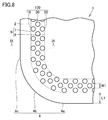
- FIG. 8 is an enlarged schematic plan view showing the configuration of the cutting tool according to the fourth embodiment.
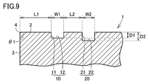
- FIG. 9 is a schematic sectional view taken along the line IX-IX in FIG.
- FIG. 10 is an enlarged schematic plan view showing the configuration of the cutting tool according to the fifth embodiment.
- FIG. 11 is a schematic sectional view taken along the line XI-XI of FIG.
- FIG. 12 is an enlarged schematic plan view showing the configuration of the cutting tool according to the sixth embodiment.
- FIG. 13 is a schematic sectional view taken along line XIII-XIII in FIG.
- FIG. 14 is a schematic sectional view showing the configuration of the cutting tool according to the seventh embodiment.
- An object of the present disclosure is to provide a cutting tool capable of reducing wear on a rake face.
- a cutting tool capable of reducing wear on a rake face According to the present disclosure, it is possible to provide a cutting tool capable of reducing wear on a rake face.
- the depth of the first recess 10 may be 50 ⁇ m or less in the direction perpendicular to the seat surface 5. If the depth of the first recessed portion 10 is large, the strength of the cutting edge 4 becomes low, and the cutting edge 4 is easily damaged. By setting the depth of the first recess 10 to be 50 ⁇ m or less, the cutting edge 4 can be prevented from being damaged.
- FIG. 2 is an enlarged schematic plan view showing the configuration of the cutting tool according to the first embodiment.
- the cutting edge 4 has a first cutting edge portion 4a, a corner cutting edge portion 4b, and a second cutting edge portion 4c when viewed from a direction perpendicular to the seat surface 5. doing.
- Each of the 1st cutting edge part 4a and the 2nd cutting edge part 4c is linear.
- the corner cutting edge portion 4b is located between the first cutting edge portion 4a and the second cutting edge portion 4c.
- the corner cutting edge portion 4b has an arc shape.
- the inner end portion 8 is a line connecting a straight line parallel to the first cutting edge portion 4a, a curve having the same curvature as the corner cutting edge portion 4b, and a straight line parallel to the second cutting edge portion 4c.
- the outer end portion 7 is a line connecting a straight line parallel to the first cutting edge part 4a, a curve having the same curvature as the corner cutting edge part 4b, and a straight line parallel to the second cutting edge part 4c. is there.
- the plurality of recesses 100 are provided in a region (recess formation region 9) between the inner end 8 and the outer end 7.
- the shape of at least a part of each of the plurality of recesses 100 may be a circle when viewed from a direction perpendicular to the seat surface 5. All the shapes of the plurality of recesses 100 may be circular, or part of the plurality of recesses 100 may be circular.
- the interval (fifth length G1) between two adjacent recesses of the plurality of recesses 100 is, for example, 10 ⁇ m or more.
- the interval (fifth length G1) between two adjacent recesses in the plurality of recesses 100 may be smaller than the width (fifth width T1) of the recesses in the direction parallel to the extending direction of the cutting edge 4. ..
- the cutting tool 1 according to the second embodiment is different from the cutting tool 1 according to the first embodiment mainly in the configuration in which the shape of the recess is rectangular, and the other configurations are the cutting according to the first embodiment. It is similar to the tool 1.
- the configuration different from the cutting tool 1 according to the first embodiment will be mainly described.
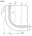
- FIG. 7 is an enlarged schematic plan view showing the configuration of the cutting tool 1 according to the third embodiment.
- the shape of at least a part of each of the plurality of recesses 100 may be a hexagon when viewed in a direction perpendicular to the seat surface 5. All the shapes of the plurality of recesses 100 may be hexagonal, or some shapes of the plurality of recesses 100 may be hexagonal. Preferably, all the shapes of the plurality of recesses 100 are regular hexagons.
- the two opposite sides of the hexagonal recessed portion located in the area facing the first cutting edge portion 4a have the first It may or may not have a special angle with the extending direction of the cutting edge portion 4a.
- the two opposite sides of the hexagonal recessed portion located in the region facing the second cutting edge portion 4c have the extending direction of the second cutting edge portion 4c. It may be parallel to a direction perpendicular to.
- the cutting tool 1 according to the fourth embodiment is different from the cutting tool 1 according to the first embodiment mainly in the configuration in which the plurality of recesses 100 have the first recess 10, the second recess 20, and the third recess 30.
- the other configurations are the same as those of the cutting tool 1 according to the first embodiment.
- the configuration different from the cutting tool 1 according to the first embodiment will be mainly described.
- FIG. 9 is a schematic sectional view taken along line IX-IX in FIG.
- the rake face 2 is provided with a first recess 10 and a second recess 20.
- the second recess 20 has a second side surface 21 and a second bottom surface 22.
- the second side surface 21 may extend in a direction substantially perpendicular to the rake surface 2.
- the second bottom surface 22 is continuous with the second side surface 21.
- the second bottom surface 22 may be substantially parallel to the rake surface 2.
- the depth of the second recess 20 (second depth D2) is smaller than the depth of the first recess 10 (first depth D1). May be larger.
- the second depth D2 is, for example, 200 ⁇ m or less.
- the second depth D2 is preferably 100 ⁇ m or less, more preferably 50 ⁇ m or less.
- the lower limit of the second depth D2 is not particularly limited, but is, for example, 10 ⁇ m or more.
- the cutting tool 1 according to the fifth embodiment is different from the cutting tool 1 according to the first embodiment mainly in the configuration in which each of the plurality of recesses 100 is an elongated groove, and other configurations are as follows. It is similar to the cutting tool 1 according to one embodiment.
- the configuration different from the cutting tool 1 according to the first embodiment will be mainly described.
- FIG. 10 is an enlarged schematic plan view showing the configuration of the cutting tool according to the fifth embodiment.
- the plurality of recesses 100 has a first recess 10, a second recess 20, and a third recess 30.
- the first recess 10 is located closest to the cutting edge 4 when viewed in a direction perpendicular to the seat surface 5.
- the second recess 20 is located farthest from the cutting edge 4 when viewed in a direction perpendicular to the seat surface 5.
- the third recess 30 is located between the first recess 10 and the second recess 20 when viewed from a direction perpendicular to the seat surface 5.
- the shortest distance between the first recess 10 and the cutting edge 4 is smaller than the shortest distance between the second recess 20 and the cutting edge 4. short.
- the shortest distance between the third concave portion 30 and the cutting edge 4 is longer than the shortest distance between the first concave portion 10 and the cutting edge 4, and the second concave portion 20. Is shorter than the shortest distance from the cutting edge 4.
- each shape of the first recess 10, the second recess 20, and the third recess 30 is an elongated groove when viewed from a direction perpendicular to the seat surface 5.
- the elongated groove has a portion parallel to the first cutting edge portion 4a, a portion having the same curvature as the corner cutting edge portion 4b, and a portion parallel to the second cutting edge portion 4c.
- each of the first recess 10, the second recess 20, and the third recess 30 is provided along the cutting edge 4 when viewed in the direction perpendicular to the seat surface 5.
- the first recess 10 and the second recess 20 may have similar shapes when viewed from a direction perpendicular to the seat surface 5.
- the first recess 10 and the third recess 30 may have similar shapes when viewed from a direction perpendicular to the seat surface 5.
- FIG. 11 is a schematic sectional view taken along line XI-XI in FIG.
- the rake face 2 is provided with a first recess 10, a second recess 20, and a third recess 30.
- the second recess 20 has a second side surface 21 and a second bottom surface 22.
- the second side surface 21 may extend in a direction substantially perpendicular to the rake surface 2.
- the second bottom surface 22 is continuous with the second side surface 21.
- the second bottom surface 22 may be substantially parallel to the rake surface 2.
- the third recess 30 has a third side surface 31 and a third bottom surface 32.
- the third side surface 31 may extend in a direction substantially perpendicular to the rake face 2.
- the third bottom surface 32 is continuous with the third side surface 31.
- the third bottom surface 32 may be substantially parallel to the rake surface 2.
- the depth of the third recess 30 may be larger than the depth of the first recess 10 (first depth D1).
- the depth of the second recess 20 (second depth D2) may be larger than the depth of the third recess 30 (third depth D3).
- the first depth D1 may be the same as the second depth D2.
- the second depth D2 may be the same as the third depth D3.
- the distance between the first recess 10 and the third recess 30 is smaller than the shortest distance between the cutting edge 4 and the first recess 10 (first length L1). It may be small.
- the width of the first recess 10 (first width W1) may be the same as or different from the width of the second recess 20 (second width W2).
- the width of the second recess 20 (second width W2) may be the same as or different from the width of the third recess 30 (third width W3).
- the cutting tool 1 according to the sixth embodiment is mainly configured such that the plurality of recesses 100 have the first recess 10, the second recess 20, the third recess 30, and the fourth recess 40, and the cutting according to the first embodiment. It is different from the tool 1, and the other configurations are the same as those of the cutting tool 1 according to the first embodiment.
- the configuration different from the cutting tool 1 according to the first embodiment will be mainly described.
- FIG. 12 is an enlarged schematic plan view showing the configuration of the cutting tool according to the sixth embodiment.
- the plurality of recesses 100 has a first recess 10, a second recess 20, a third recess 30, and a fourth recess 40.
- the first recess 10 is located closest to the cutting edge 4 when viewed in a direction perpendicular to the seat surface 5.
- the second recess 20 is located farthest from the cutting edge 4 when viewed in a direction perpendicular to the seat surface 5.
- the third recess 30 is located between the first recess 10 and the second recess 20 when viewed from a direction perpendicular to the seat surface 5. From another viewpoint, in the direction perpendicular to the extending direction of the cutting edge 4, the shortest distance between the first recess 10 and the cutting edge 4 is smaller than the shortest distance between the second recess 20 and the cutting edge 4. short. In the direction perpendicular to the extending direction of the cutting edge 4, the shortest distance between the third concave portion 30 and the cutting edge 4 is longer than the shortest distance between the first concave portion 10 and the cutting edge 4, and the second concave portion 20. Is shorter than the shortest distance from the cutting edge 4.
- the fourth recess 40 is located between the third recess 30 and the second recess 20 when viewed from a direction perpendicular to the seat surface 5. From another viewpoint, in the direction perpendicular to the extending direction of the cutting edge 4, the shortest distance between the third recess 30 and the cutting edge 4 is smaller than the shortest distance between the second recess 20 and the cutting edge 4. short. The shortest distance between the fourth recess 40 and the cutting edge 4 is longer than the shortest distance between the third recess 30 and the cutting edge 4 and shorter than the shortest distance between the second recess 20 and the cutting edge 4.
- the shape of the first recess 10 is an elongated groove when viewed from a direction perpendicular to the seat surface 5.
- the second recess 20 has a rectangular shape when viewed from a direction perpendicular to the seat surface 5.
- the third recess 30 has a circular shape when viewed from a direction perpendicular to the seat surface 5.
- the fourth recess 40 has a hexagonal shape when viewed in a direction perpendicular to the seat surface 5.
- FIG. 13 is a schematic sectional view taken along line XIII-XIII in FIG.
- the rake face 2 is provided with a first recess 10, a second recess 20, a third recess 30, and a fourth recess 40.
- the second recess 20 has a second side surface 21 and a second bottom surface 22.
- the second side surface 21 may extend in a direction substantially perpendicular to the rake surface 2.
- the second bottom surface 22 is continuous with the second side surface 21.
- the second bottom surface 22 may be substantially parallel to the rake surface 2.
- the third recess 30 has a third side surface 31 and a third bottom surface 32.
- the third side surface 31 may extend in a direction substantially perpendicular to the rake face 2.
- the third bottom surface 32 is continuous with the third side surface 31.
- the third bottom surface 32 may be substantially parallel to the rake surface 2.
- the fourth recess 40 has a fourth side surface 41 and a fourth bottom surface 42.
- the fourth side surface 41 may extend in a direction substantially perpendicular to the rake face 2.
- the fourth bottom surface 42 is continuous with the fourth side surface 41.
- the fourth bottom surface 42 may be substantially parallel to the rake surface 2.
- the distance between the first recess 10 and the third recess 30 is smaller than the shortest distance between the cutting edge 4 and the first recess 10 (first length L1). It may be small.
- the width of the first recess 10 (first width W1) may be smaller than the width of the third recess 30 (third width W3).
- the interval (third length L3) between the third recess 30 and the fourth recess 40 may be larger than the interval (second length L2) between the first recess 10 and the third recess 30.
- the width of the third recess 30 (third width W3) may be smaller than the width of the fourth recess 40 (fourth width W4).
- the interval (fourth length L4) between the fourth recess 40 and the second recess 20 may be larger than the interval (third length L3) between the third recess 30 and the fourth recess 40.
- the width of the fourth recess 40 (the fourth width W4) may be larger than the width of the second recess 20 (the second width W2).
- the ratio of the total area of each of the plurality of recesses 100 to the recess forming region 9 from the first recess 10 to the second recess 20 is, for example, 30% or more and 70% or less. is there.
- the recess forming region 9 is a region surrounded by the inner end portion 8, the outer end portion 7, the one end portion 14, and the other end portion 13.
- the one end 14 is a straight line that is in contact with the plurality of recesses 100 on one side of the extending direction of the cutting edge 4 (on the side of the first cutting edge 4a).
- the other end 13 is a straight line that is in contact with the plurality of recesses 100 on the other side (the side of the second cutting edge 4c) in the extending direction of the cutting edge 4. All of the plurality of recesses 100 are formed inside the recess forming region 9. From another point of view, the plurality of recesses 100 are not formed outside the recess forming region 9.
- the ratio of the total area of each of the plurality of recesses 100 to the recess forming region 9 is preferably 35% or more, more preferably 40% or more.
- the ratio of the total area of each of the plurality of recesses 100 to the recess forming region 9 is preferably 65% or less, more preferably 60% or less.
- the cutting tool 1 according to the seventh embodiment is different from the cutting tool 1 according to the first embodiment mainly in the configuration in which the cutting tool 1 has a base material and a coating film, and other configurations are the same as those in the first embodiment. It is similar to the cutting tool 1 according to the embodiment.
- the configuration different from the cutting tool 1 according to the first embodiment will be mainly described.
- FIG. 14 is a schematic cross-sectional view showing the configuration of the cutting tool according to the seventh embodiment.
- the cutting tool 1 has a base material 51 and a coating film 52.
- the coating film 52 covers the base material 51.
- the rake face 2 is composed of the coating 52.
- the flank 3 is formed by the coating 52.
- the cutting edge 4 is composed of a coating 52.
- the thickness H of the coating 52 is, for example, 3 ⁇ m.
- the material of the coating film 52 is not particularly limited, but is TiAlN (titanium aluminum nitride), for example.
- the first recess 10 has a first side surface 11 and a first bottom surface 12.
- the first bottom surface 12 is made of, for example, the base material 51.
- the first side surface 11 is composed of, for example, a base material 51 and a coating film 52. From another viewpoint, the first recess 10 penetrates the coating 52.
- the depth of the first recess 10 (first depth D1) is, for example, 50 ⁇ m or less.
- the thickness H of the coating 52 may be smaller than the first depth D1.
- the cutting tool 1 has been described as a cutting edge replaceable insert for turning, but the cutting tool 1 according to the present embodiment is not limited to the above cutting insert.
- the cutting tool 1 according to the present embodiment may be a cutting edge exchangeable tip applied to a rotary cutting tool such as a drill or an end mill.
- the work material is, for example, a titanium alloy, but is not limited to the titanium alloy.
- the recess provided in the rake face 2 of the cutting tool 1 according to the present embodiment can be formed, for example, by performing sintering after press-molding with a mold in which the shape of the recess is transferred or by using injection molding. it can.
- a press body formed by embossing with a normal mold that does not transfer the shape of the recess is sintered at 700° C.
- the recess is formed by a known molding method of Next, the intermediate sintered body in which the recess is formed may be further sintered to produce a cutting insert in which the recess is formed.
- the recesses may be formed in the cemented carbide obtained by sintering by laser processing.
- the laser used for laser processing is preferably a picosecond laser.
- the recess may be formed by using a technique such as focused ion beam, reactive ion etching, electric discharge machining or wet etching.
- the contact area between the rake face 2 and the chips can be reduced by providing the rake face 2 with the plurality of recesses 100. Therefore, wear of the rake face 2 can be reduced.
- the width of each of the plurality of recesses 100 is 60 ⁇ m or less, the chips of the work material adhere to the recesses. Therefore, the concave portion is filled with the chips. As a result, the contact area between the rake face 2 and the chips cannot be reduced.
- the width of each of the plurality of recesses 100 is larger than 400 ⁇ m, the chips contact the bottom surface of the recess.
- the shortest distance between the cutting edge 4 and the first recess 10 may be 30 ⁇ m or more when viewed from the direction perpendicular to the seat surface 5.
- the strength of the cutting edge 4 becomes low and the cutting edge 4 is easily broken.
- the depth of the first recess 10 may be 50 ⁇ m or less in the direction perpendicular to the seat surface 5. If the depth of the first recessed portion 10 is large, the strength of the cutting edge 4 becomes low, and the cutting edge 4 is easily damaged. By setting the depth of the first recess 10 to be 50 ⁇ m or less, the cutting edge 4 can be prevented from being damaged.
- the cutting tool 1 when viewed from the direction perpendicular to the seat surface 5, the total number of each of the plurality of recesses 100 with respect to the recess forming region 9 from the first recess 10 to the second recess 20 is large.
- the area ratio may be 30% or more and 70% or less.
- the depth of the second recess 20 may be larger than the depth of the first recess 10 in the direction perpendicular to the seat surface 5.
- the rake face 2 is worn and the depth of the recess is reduced. Therefore, it is desirable that the depth of the recess be large.
- the strength of the cutting edge 4 is reduced, which is not desirable.
- each of the plurality of recesses 100 may have a circular shape when viewed from the direction perpendicular to the seat surface 5.
- the width is the same from any direction. Therefore, wear of the rake face 2 can be reduced regardless of the direction in which the chips of the work material flow.
- the base material of the cutting tool 1 was a cemented carbide base material (shape: CNMG120408N-EX) made of Sumitomo Electric Hard Metal.
- the base material was fixed to a laser ablation device, and the rake face 2 of the base material was irradiated with laser light to form recesses.
- a YAG laser was used as the laser.
- the oscillation wavelength was 532 nm.
- the output was set to 500W.
- the shape of the recess after laser processing was measured using an optical microscope (Digital Microscope VHX5000 manufactured by Keyence Corporation).
- the shape of the recess is a circle, a rectangle, a square, a regular hexagon, a regular octagon, or a groove.
- the width of the recess (first width W1) is as shown in Table 1.
- the rake face 2 has no recess.
- the first length L1 was 100 ⁇ m.
- the depth of the recess (first depth D1) was 20 ⁇ m.
- the area ratio of the recesses (that is, the ratio of the total area of each of the plurality of recesses 100 to the recess forming region 9) was set to 50%.
- the cutting tools 1 according to Samples 2-1 to 2-10 were prepared.
- As the raw material powder 0.27 mass% Cr 3 C 2 powder, 6.0 mass% Co, and 93.73 mass% WC were mixed.
- the mixture was pulverized and mixed in an ethanol solvent with an attritor for 7 hours, and then granulated and dried to prepare a granulated powder.
- the obtained granulated powder was press-molded using a mold produced according to a predetermined texture shape, and held at 1400° C. for 1 hour in an argon atmosphere of 2 kPa. Then, it was cooled to 1280° C. at a rate of 100° C./min, held at 1280° C.
- the shape of the recess is a circle, a rectangle, or a regular octagon.
- the width of the recess (first width W1) was 100 ⁇ m.
- the first length L1 was 100 ⁇ m.
- the depth of the recess (first depth D1) was 20 ⁇ m.
- the area ratio of the recesses (that is, the ratio of the total area of each of the plurality of recesses 100 to the recess forming region 9) was set to 20% or more and 75% or less.
- the cutting tools 1 according to Samples 3-1 to 3-5 were prepared.
- As the raw material powder 0.27 mass% Cr 3 C 2 powder as the raw material powder, 6.0 mass% Co, 93.73 mass% WC and a binder were kneaded.
- a part of the cutting edge was formed by injection molding and attached to a base metal of cemented carbide by brazing.
- the cutting tool 1 having the shape of CNMG120408N-EX was manufactured.
- the shape of the recess is a circle or a rectangle.
- the width of the recess (first width W1) was 100 ⁇ m.
- the first length L1 was 25 ⁇ m or more and 200 ⁇ m or less.
- the depth of the recess (first depth D1) was 20 ⁇ m.
- the area ratio of the recesses (that is, the ratio of the total area of each of the plurality of recesses 100 to the recess forming region 9) was set to 50%.
- the cutting tools 1 according to Samples 4-1 to 4-5 were prepared.
- As the raw material powder 0.27 mass% Cr 3 C 2 powder as the raw material powder, 6.0 mass% Co, 93.73 mass% WC and a binder were kneaded.
- a part of the cutting edge was formed by injection molding and attached to a base metal of cemented carbide by brazing.
- the cutting tool 1 having the shape of CNMG120408N-EX was manufactured.
- the shape of the recess is a circle or a rectangle.
- the width of the recess (first width W1) was 100 ⁇ m.
- the first length L1 was 100 ⁇ m.
- the depth of the recess (first depth D1) was set to 5 ⁇ m or more and 60 ⁇ m or less.
- the area ratio of the recesses (that is, the ratio of the total area of each of the plurality of recesses 100 to the recess forming region 9) was set to 50%.
- the cutting tools 1 according to Samples 5-1 to 5-8 were prepared.
- As the raw material powder 0.27 mass% Cr 3 C 2 powder as the raw material powder, 6.0 mass% Co, 93.73 mass% WC and a binder were kneaded.
- a part of the cutting edge was formed by injection molding and attached to a base metal of cemented carbide by brazing.
- the cutting tool 1 having the shape of CNMG120408N-EX was manufactured.
- the shape of the recess was a circle.
- the width of the recess (first width W1) was 100 ⁇ m.
- the first length L1 was 100 ⁇ m.
- the depth of the first recess 10 (first depth D1) was set to 10 ⁇ m or more and 100 ⁇ m or less.
- the depth of the second recess 20 (second depth D2) was set to 10 ⁇ m or more and 200 ⁇ m or less.
- the area ratio of the recesses (that is, the ratio of the total area of each of the plurality of recesses 100 to the recess forming region 9) was set to 50%.
- the base material of the cutting tool 1 was a cemented carbide base material (shape: CNMG120408N-EX) made of Sumitomo Electric Hard Metal.
- a TiAlN coating 52 having a thickness of 3 ⁇ m was formed on the substrate by using an ion plating method.
- the base material on which the coating 52 was formed was fixed to a laser ablation device, and the rake face 2 was irradiated with laser light to form a recess.
- a YAG laser was used as the laser.
- the oscillation wavelength was 266 nm.
- the output was set to 500W.
- the shape of the recess after laser processing was measured using an optical microscope (Digital Microscope VHX5000 manufactured by Keyence Corporation).
- the shape of the recess was a circle.
- the width of the recess (first width W1) is as shown in Table 6.
- the rake face 2 is not provided with a recess.
- the first length L1 was 100 ⁇ m.
- the depth of the recess (first depth D1) was 20 ⁇ m.
- the area ratio of the recesses (that is, the ratio of the total area of each of the plurality of recesses 100 to the recess forming region 9) was set to 50%.
- the base material of the cutting tool 1 was a cemented carbide base material (shape: CNMG120408N-EX) made of Sumitomo Electric Hard Metal.
- a TiAlN coating 52 having a thickness of 3 ⁇ m was formed on the substrate by using an ion plating method.
- the base material on which the coating 52 was formed was fixed to a laser ablation device, and the rake face 2 was irradiated with laser light to form a recess.
- a YAG laser was used as the laser.
- the oscillation wavelength was 532 nm.
- the output was set to 500W.
- the shape of the recess after laser processing was measured using an optical microscope (Digital Microscope VHX5000 manufactured by Keyence Corporation).
- the shape of the recess was a circle.
- the width of the recess (first width W1) is as shown in Table 7.
- the rake face 2 has no recess.
- the first length L1 was 100 ⁇ m.
- the depth of the recess (first depth D1) was 20 ⁇ m.
- the area ratio of the recesses (that is, the ratio of the total area of each of the plurality of recesses 100 to the recess forming region 9) was set to 50%.
Landscapes
- Engineering & Computer Science (AREA)
- Mechanical Engineering (AREA)
- Cutting Tools, Boring Holders, And Turrets (AREA)
Abstract
切削工具は、すくい面と、逃げ面と、座面とを有している。逃げ面は、すくい面に連なっている。座面は、すくい面と反対側にある。すくい面と逃げ面との稜線は、切れ刃を構成している。すくい面には、複数の凹部が設けられている。座面に対して垂直な方向から見て、切れ刃の延在方向に対して垂直な方向において、複数の凹部の各々の幅は、60μmより大きく400μm以下である。
Description
本開示は、切削工具に関する。本出願は、2019年2月14日に出願した日本特許出願である特願2019-024125号に基づく優先権を主張する。当該日本特許出願に記載された全ての記載内容は、参照によって本明細書に援用される。
特開2009-113120号公報(特許文献1)には、すくい面に多数の溝が設けられた切削工具が開示されている。溝に切削液を溜めることにより、高い潤滑性が得られる。また特表2016-500028号公報(特許文献2)には、パターン化された表面領域を有する切削工具が開示されている。
本開示に係る切削工具は、すくい面と、逃げ面と、座面とを備えている。逃げ面は、すくい面に連なっている。座面は、すくい面と反対側にある。すくい面と逃げ面との稜線は、切れ刃を構成している。すくい面には、複数の凹部が設けられている。座面に対して垂直な方向から見て、切れ刃の延在方向に対して垂直な方向において、複数の凹部の各々の幅は、60μmより大きく400μm以下である。
[本開示が解決しようとする課題]
しかしながら、単にすくい面に多数の溝を設けただけでは、被削材の切り屑が溝の内部に凝着し、溝に切削液を溜めることができない。そのため、すくい面の摩耗を十分に低減することができない。
しかしながら、単にすくい面に多数の溝を設けただけでは、被削材の切り屑が溝の内部に凝着し、溝に切削液を溜めることができない。そのため、すくい面の摩耗を十分に低減することができない。
本開示の目的は、すくい面の摩耗を低減可能な切削工具を提供することである。
[本開示の効果]
本開示によれば、すくい面の摩耗を低減可能な切削工具を提供することができる。
[本開示の実施形態の説明]
最初に本開示の実施形態を列記して説明する。
[本開示の効果]
本開示によれば、すくい面の摩耗を低減可能な切削工具を提供することができる。
[本開示の実施形態の説明]
最初に本開示の実施形態を列記して説明する。
(1)本開示に係る切削工具1は、すくい面2と、逃げ面3と、座面5とを備えている。逃げ面3は、すくい面2に連なっている。座面5は、すくい面2と反対側にある。すくい面2と逃げ面3との稜線は、切れ刃4を構成している。すくい面2には、複数の凹部100が設けられている。座面5に対して垂直な方向から見て、切れ刃4の延在方向に対して垂直な方向において、複数の凹部100の各々の幅は、60μmより大きく400μm以下である。
上記(1)に係る切削工具1においては、すくい面2に複数の凹部100を設けることにより、すくい面2と切り屑との接触面積を低減することができる。そのため、すくい面2の摩耗を低減することができる。複数の凹部100の各々の幅が60μm以下の場合においては、凹部に被削材の切り屑が凝着する。そのため、凹部が切り屑によって埋まってしまう。結果として、すくい面2と切り屑との接触面積を低減することができない。一方、複数の凹部100の各々の幅が400μmよりも大きい場合においては、切り屑が凹部の底面に接触する。そのため、切り屑との抵抗が大きくなり、すくい面2の摩耗を十分に低減することができない。複数の凹部100の各々の幅を60μmより大きく400μm以下とすることにより、すくい面2の摩耗を低減することができる。
(2)上記(1)に係る切削工具1によれば、座面5に対して垂直な方向から見て、複数の凹部100は、切れ刃4の最も近くに位置する第1凹部10を含んでいてもよい。
(3)上記(2)に係る切削工具1によれば、座面5に対して垂直な方向から見て、切れ刃4と第1凹部10との最短距離は、30μm以上であってもよい。切れ刃4の近くに第1凹部10が設けられていると、切れ刃4の強度が低くなり、切れ刃4が欠損しやすくなる。切れ刃4と第1凹部10との最短距離を30μm以上とすることにより、切れ刃4が欠損することを抑制することができる。
(4)上記(2)または(3)に係る切削工具1によれば、座面5に対して垂直な方向において、第1凹部10の深さは、50μm以下であってもよい。第1凹部10の深さが大きいと、切れ刃4の強度が低くなり、切れ刃4が欠損しやすくなる。第1凹部10の深さを50μm以下とすることにより、切れ刃4が欠損することを抑制することができる。
(5)上記(2)から(4)のいずれかに係る切削工具1によれば、座面5に対して垂直な方向から見て、複数の凹部100は、切れ刃4から最も遠くに位置する第2凹部20を含んでいてもよい。
(6)上記(5)に係る切削工具1によれば、座面5に対して垂直な方向から見て、第1凹部10から第2凹部20までの凹部形成領域9に対する複数の凹部100の各々の総面積の比率は、30%以上70%以下であってもよい。これにより、切削工具1の強度を過度に低減することなく、すくい面2の摩耗を低減することができる。
(7)上記(5)または(6)に係る切削工具1によれば、座面5に対して垂直な方向において、第2凹部20の深さは、第1凹部10の深さよりも大きくてもよい。切削工具1を使用するに従って、すくい面2が摩耗することにより、凹部の深さは小さくなる。そのため、凹部の深さは、大きい方が望ましい。一方、凹部の深さが大きくなると、切れ刃4の強度が低下するため望ましくない。切れ刃4から遠くに位置する第2凹部20の深さを、切れ刃4の近くに位置する第1凹部10の深さよりも大きくすることにより、切れ刃4の強度を過度に低減することなく、長い期間、すくい面2の摩耗を低減することができる。
(8)上記(1)から(7)のいずれかに係る切削工具1によれば、座面5に対して垂直な方向から見て、複数の凹部100の各々の少なくとも一部の形状は、円であってもよい。円の場合、どの方向から見ても、幅は同じである。そのため、被削材の切り屑がどの方向から流れてきても、すくい面2の摩耗を低減することができる。
(9)上記(1)から(7)のいずれかに係る切削工具1によれば、座面5に対して垂直な方向から見て、複数の凹部100の各々の少なくとも一部の形状は、矩形であってもよい。
[本開示の実施形態の詳細]
次に、図面に基づいて本開示の実施形態の詳細について説明する。なお、以下の図面において同一または相当する部分には同一の参照番号を付し、その説明は繰返さない。
[本開示の実施形態の詳細]
次に、図面に基づいて本開示の実施形態の詳細について説明する。なお、以下の図面において同一または相当する部分には同一の参照番号を付し、その説明は繰返さない。
(第1実施形態)
まず、第1実施形態に係る切削工具の構成について説明する。図1は、第1実施形態に係る切削工具の構成を示す斜視模式図である。
まず、第1実施形態に係る切削工具の構成について説明する。図1は、第1実施形態に係る切削工具の構成を示す斜視模式図である。
図1に示されるように、第1実施形態に係る切削工具1は、たとえば旋削加工用の切削インサートであり、すくい面2と、座面5と、逃げ面3と、取付孔6とを主に有している。座面5は、すくい面2の反対側にある。座面5は、切削工具1がバイト(図示せず)に取り付けられる面である。座面5は、平坦な面である。逃げ面3は、すくい面2に連なっている。座面5は、逃げ面3に連なっている。取付孔6は、すくい面2と座面5との間を貫通している。逃げ面3は、取付孔6を取り囲んでいる。すくい面2と逃げ面3との稜線は、切れ刃4を構成している。
図2は、第1実施形態に係る切削工具の構成を示す拡大平面模式図である。図2に示されるように、座面5に対して垂直な方向から見て、切れ刃4は、第1切刃部4aと、コーナー切刃部4bと、第2切刃部4cとを有している。第1切刃部4aおよび第2切刃部4cの各々は、直線状である。コーナー切刃部4bは、第1切刃部4aと第2切刃部4cとの間に位置している。コーナー切刃部4bは、円弧状である。
すくい面2には、複数の凹部100が設けられている。図2に示されるように、座面5に対して垂直な方向から見て、複数の凹部100は、内側端部8と、外側端部7との間に位置している。内側端部8および外側端部7の各々は、複数の凹部100の外形に沿った線である。外側端部7は、切れ刃4を取付孔6に向かって平行移動させた線である。内側端部8は、外側端部7を取付孔6に向かって平行移動させた線である。外側端部7は、切れ刃4と内側端部8との間に位置している。内側端部8は、第1切刃部4aに平行な直線と、コーナー切刃部4bと同じ曲率を有する曲線と、第2切刃部4cに平行な直線とを繋いだ線である。同様に、外側端部7は、第1切刃部4aに平行な直線と、コーナー切刃部4bと同じ曲率を有する曲線と、第2切刃部4cに平行な直線とを繋いだ線である。複数の凹部100は、内側端部8と外側端部7との間の領域(凹部形成領域9)に設けられている。
図2に示されるように、座面5に対して垂直な方向から見て、切れ刃4の延在方向に対して垂直な方向において、複数の凹部100の各々の幅(第1幅W1)は、60μmより大きく400μm以下である。切れ刃4の延在方向とは、切れ刃4の接線方向である。第1切刃部4aに対向する領域に位置する凹部の幅は、直線状の第1切刃部4aに対して垂直な方向における凹部の幅である。コーナー切刃部4bに対向する領域に位置する凹部の幅は、コーナー切刃部4bの接線に対して垂直な方向における凹部の幅である。第2切刃部4cに対向する領域に位置する凹部の幅は、直線状の第2切刃部4cに対して垂直な方向における凹部の幅である。
図2に示されるように、座面5に対して垂直な方向から見て、切れ刃4の延在方向に対して垂直な方向において、複数の凹部100の各々の幅(第1幅W1)は、好ましくは80μm以上であり、より好ましくは100μm以上である。座面5に対して垂直な方向から見て、切れ刃4の延在方向に対して垂直な方向において、複数の凹部100の各々の幅(第1幅W1)は、好ましくは200μm以下であり、より好ましくは150μm以下である。
図2に示されるように、座面5に対して垂直な方向から見て、切れ刃4と複数の凹部100(第1凹部10)との最短距離(第1長さL1)は、たとえば30μm以上であってもよい。具体的には、座面5に対して垂直な方向から見て、切れ刃4と外側端部7との最短距離は、たとえば30μm以上である。別の観点から言えば、切れ刃4から取付孔6に向かって30μm以内の領域には、凹部が設けられていない。第1長さL1は、好ましくは50μm以上であり、より好ましくは100μm以上である。
図2に示されるように、座面5に対して垂直な方向から見て、複数の凹部100の各々の少なくとも一部の形状は、円であってもよい。複数の凹部100の全ての形状が円であってもよいし、複数の凹部100の一部の形状が円であってもよい。複数の凹部100の内、隣り合う2つの凹部の間隔(第5長さG1)は、たとえば10μm以上である。複数の凹部100の内、隣り合う2つの凹部の間隔(第5長さG1)は、切れ刃4の延在方向に平行な方向における凹部の幅(第5幅T1)よりも小さくてもよい。
図3は、図2のIII-III線に沿った断面模式図である。図3に示されるように、凹部(第1凹部10)は、第1側面11と、第1底面12とを有している。第1側面11は、すくい面2に対してほぼ垂直な方向に延在していてもよい。第1底面12は、第1側面11に連なっている。第1底面12は、すくい面2とほぼ平行であってもよい。図3に示されるように、座面5に対して垂直な方向において、第1凹部10の深さ(第1深さD1)は、たとえば50μm以下である。第1深さD1は、好ましくは20μm以下であり、より好ましくは10μm以下である。第1深さD1の下限は、特に限定されないが、たとえば5μm以上である。
本実施形態に係る切削工具1において、すくい面2と逃げ面3とにより形成される角度(第1角度θ1)は、特に限定されない(図3参照)。第1角度θ1は、90°以下であってもよいし、90°よりも大きくてもよい。また本実施形態にかかる切削工具1と被削材との接触角度も90度以上であっても90度以下であってもよい。
図4は、第1実施形態の第1変形例に係る切削工具の構成を示す断面模式図である。図4に示されるように、第1側面11は、すくい面2に対して垂直な面に対して傾斜していてもよい。第1凹部10の幅は、第1底面12からすくい面2に向かうにつれて拡がっている。第1側面11とすくい面2とにより形成される角度(第2角度θ2)は、90°よりも大きく180°よりも小さい。第1側面11は、平面である。
図5は、第1実施形態の第2変形例に係る切削工具の構成を示す断面模式図である。図5に示されるように、第1側面11および第1底面12の各々は、曲面であってもよい。具体的には、第1側面11および第1底面12の各々は、球面の一部であってもよい。第1側面11の曲率半径は、第1底面12の曲率半径と同じであってもよいし、異なっていてもよい。
(第2実施形態)
次に、第2実施形態に係る切削工具1の構成について説明する。第2実施形態に係る切削工具1は、主に凹部の形状が矩形である構成において、第1実施形態に係る切削工具1と異なっており、その他の構成については、第1実施形態に係る切削工具1と同様である。以下、第1実施形態に係る切削工具1と異なる構成を中心に説明する。
次に、第2実施形態に係る切削工具1の構成について説明する。第2実施形態に係る切削工具1は、主に凹部の形状が矩形である構成において、第1実施形態に係る切削工具1と異なっており、その他の構成については、第1実施形態に係る切削工具1と同様である。以下、第1実施形態に係る切削工具1と異なる構成を中心に説明する。
図6は、第2実施形態に係る切削工具の構成を示す拡大平面模式図である。図6に示されるように、座面5に対して垂直な方向から見て、複数の凹部100の各々の少なくとも一部の形状は、矩形(長方形)であってもよい。複数の凹部100の全ての形状が矩形であってもよいし、複数の凹部100の一部の形状が矩形であってもよい。
凹部の形状は、長方形であってもよいし、正方形であってもよい。座面5に対して垂直な方向から見て、切れ刃4の延在方向に沿った方向と平行な方向における凹部の幅(第5幅T1)は、切れ刃4の延在方向に対して垂直な方向における凹部の幅(第1幅W1)よりも大きくてもよい。隣り合う2つの凹部の間の間隔(第5長さG1)は、切れ刃4の延在方向に沿った方向と平行な方向における凹部の幅(第5幅T1)よりも小さくてもよい。
(第3実施形態)
次に、第3実施形態に係る切削工具1の構成について説明する。第3実施形態に係る切削工具1は、主に凹部の形状が六角形である構成において、第1実施形態に係る切削工具1と異なっており、その他の構成については、第1実施形態に係る切削工具1と同様である。以下、第1実施形態に係る切削工具1と異なる構成を中心に説明する。
次に、第3実施形態に係る切削工具1の構成について説明する。第3実施形態に係る切削工具1は、主に凹部の形状が六角形である構成において、第1実施形態に係る切削工具1と異なっており、その他の構成については、第1実施形態に係る切削工具1と同様である。以下、第1実施形態に係る切削工具1と異なる構成を中心に説明する。
図7は、第3実施形態に係る切削工具1の構成を示す拡大平面模式図である。図7に示されるように、座面5に対して垂直な方向から見て、複数の凹部100の各々の少なくとも一部の形状は、六角形であってもよい。複数の凹部100の全ての形状が六角形であってもよいし、複数の凹部100の一部の形状が六角形であってもよい。好ましくは、複数の凹部100の全ての形状が正六角形である。
図7に示されるように、座面5に対して垂直な方向から見て、第1切刃部4aに対向する領域に位置している六角形状の凹部の対向する2つの辺は、第1切刃部4aの延在方向と特別な角度であってもなくてもよい。座面5に対して垂直な方向から見て、第2切刃部4cに対向する領域に位置している六角形状の凹部の対向する2つの辺は、第2切刃部4cの延在方向に対して垂直な方向に平行であってもよい。
(第4実施形態)
次に、第4実施形態に係る切削工具1の構成について説明する。第4実施形態に係る切削工具1は、主に複数の凹部100が第1凹部10と第2凹部20と第3凹部30とを有する構成において、第1実施形態に係る切削工具1と異なっており、その他の構成については、第1実施形態に係る切削工具1と同様である。以下、第1実施形態に係る切削工具1と異なる構成を中心に説明する。
次に、第4実施形態に係る切削工具1の構成について説明する。第4実施形態に係る切削工具1は、主に複数の凹部100が第1凹部10と第2凹部20と第3凹部30とを有する構成において、第1実施形態に係る切削工具1と異なっており、その他の構成については、第1実施形態に係る切削工具1と同様である。以下、第1実施形態に係る切削工具1と異なる構成を中心に説明する。
図8は、第4実施形態に係る切削工具の構成を示す拡大平面模式図である。図8に示されるように、複数の凹部100は、第1凹部10と、第2凹部20と、第3凹部30とを有している。図8に示されるように、座面5に対して垂直な方向から見て、第1凹部10は、切れ刃4の最も近くに位置している。座面5に対して垂直な方向から見て、第2凹部20は、切れ刃4から最も遠くに位置している。座面5に対して垂直な方向から見て、第3凹部30は、第1凹部10と、第2凹部20との間に位置している。別の観点から言えば、切れ刃4の延在方向に対して垂直な方向において、第1凹部10と切れ刃4との最短距離は、第2凹部20と切れ刃4との最短距離よりも短い。第3凹部30と切れ刃4との最短距離は、第1凹部10と切れ刃4との最短距離よりも長く、かつ第2凹部20と切れ刃4との最短距離よりも短い。
図8に示されるように、切れ刃4の延在方向において、第3凹部30は、第1凹部10および第2凹部20の各々に対して半周期ずれて配置されていてもよい。具体的には、切れ刃4の延在方向において、第3凹部30は、隣り合う2つの第1凹部10の間に位置していてもよい。同様に、切れ刃4の延在方向において、第3凹部30は、隣り合う2つの第2凹部20の間に位置していてもよい。
図9は、図8のIX-IX線に沿った断面模式図である。図9に示されるように、すくい面2には、第1凹部10と、第2凹部20とが設けられている。第2凹部20は、第2側面21と、第2底面22とを有している。第2側面21は、すくい面2に対してほぼ垂直な方向に延在していてもよい。第2底面22は、第2側面21に連なっている。第2底面22は、すくい面2とほぼ平行であってもよい。図9に示されるように、座面5に対して垂直な方向において、第2凹部20の深さ(第2深さD2)は、第1凹部10の深さ(第1深さD1)よりも大きくてもよい。第2深さD2は、たとえば200μm以下である。第2深さD2は、好ましくは100μm以下であり、より好ましくは50μm以下である。第2深さD2の下限は、特に限定されないが、たとえば10μm以上である。
(第5実施形態)
次に、第5実施形態に係る切削工具1の構成について説明する。第5実施形態に係る切削工具1は、主に複数の凹部100の各々の形状が細長い溝である構成において、第1実施形態に係る切削工具1と異なっており、その他の構成については、第1実施形態に係る切削工具1と同様である。以下、第1実施形態に係る切削工具1と異なる構成を中心に説明する。
次に、第5実施形態に係る切削工具1の構成について説明する。第5実施形態に係る切削工具1は、主に複数の凹部100の各々の形状が細長い溝である構成において、第1実施形態に係る切削工具1と異なっており、その他の構成については、第1実施形態に係る切削工具1と同様である。以下、第1実施形態に係る切削工具1と異なる構成を中心に説明する。
図10は、第5実施形態に係る切削工具の構成を示す拡大平面模式図である。図10に示されるように、複数の凹部100は、第1凹部10と、第2凹部20と、第3凹部30とを有している。図10に示されるように、座面5に対して垂直な方向から見て、第1凹部10は、切れ刃4の最も近くに位置している。座面5に対して垂直な方向から見て、第2凹部20は、切れ刃4から最も遠くに位置している。座面5に対して垂直な方向から見て、第3凹部30は、第1凹部10と、第2凹部20との間に位置している。別の観点から言えば、切れ刃4の延在方向に対して垂直な方向において、第1凹部10と切れ刃4との最短距離は、第2凹部20と切れ刃4との最短距離よりも短い。切れ刃4の延在方向に対して垂直な方向において、第3凹部30と切れ刃4との最短距離は、第1凹部10と切れ刃4との最短距離よりも長く、かつ第2凹部20と切れ刃4との最短距離よりも短い。
図10に示されるように、座面5に対して垂直な方向から見て、第1凹部10、第2凹部20および第3凹部30の各々の形状は、細長い溝である。細長い溝は、第1切刃部4aに平行な部分と、コーナー切刃部4bと同じ曲率を有する部分と、第2切刃部4cに平行な部分とを有している。別の観点から言えば、座面5に対して垂直な方向から見て、第1凹部10、第2凹部20および第3凹部30の各々は、切れ刃4に沿って設けられている。座面5に対して垂直な方向から見て、第1凹部10と、第2凹部20とは、相似形であってもよい。同様に、座面5に対して垂直な方向から見て、第1凹部10と、第3凹部30とは、相似形であってもよい。
図11は、図10のXI-XI線に沿った断面模式図である。図11に示されるように、すくい面2には、第1凹部10と、第2凹部20と、第3凹部30とが設けられている。第2凹部20は、第2側面21と、第2底面22とを有している。第2側面21は、すくい面2に対してほぼ垂直な方向に延在していてもよい。第2底面22は、第2側面21に連なっている。第2底面22は、すくい面2とほぼ平行であってもよい。第3凹部30は、第3側面31と、第3底面32とを有している。第3側面31は、すくい面2に対してほぼ垂直な方向に延在していてもよい。第3底面32は、第3側面31に連なっている。第3底面32は、すくい面2とほぼ平行であってもよい。
図11に示されるように、第3凹部30の深さ(第3深さD3)は、第1凹部10の深さ(第1深さD1)よりも大きくてもよい。座面5に対して垂直な方向において、第2凹部20の深さ(第2深さD2)は、第3凹部30の深さ(第3深さD3)よりも大きくてもよい。代替的に、第1深さD1は、第2深さD2と同じであってもよい。同様に、第2深さD2は、第3深さD3と同じであってもよい。
図11に示されるように、第1凹部10と第3凹部30との間隔(第2長さL2)は、切れ刃4と第1凹部10との最短距離(第1長さL1)よりも小さくてもよい。第1凹部10の幅(第1幅W1)は、第2凹部20の幅(第2幅W2)と同じであってもよいし、異なっていてもよい。同様に、第2凹部20の幅(第2幅W2)は、第3凹部30の幅(第3幅W3)と同じであってもよいし、異なっていてもよい。
(第6実施形態)
次に、第6実施形態に係る切削工具1の構成について説明する。第6実施形態に係る切削工具1は、主に複数の凹部100が第1凹部10と第2凹部20と第3凹部30と第4凹部40とを有する構成において、第1実施形態に係る切削工具1と異なっており、その他の構成については、第1実施形態に係る切削工具1と同様である。以下、第1実施形態に係る切削工具1と異なる構成を中心に説明する。
次に、第6実施形態に係る切削工具1の構成について説明する。第6実施形態に係る切削工具1は、主に複数の凹部100が第1凹部10と第2凹部20と第3凹部30と第4凹部40とを有する構成において、第1実施形態に係る切削工具1と異なっており、その他の構成については、第1実施形態に係る切削工具1と同様である。以下、第1実施形態に係る切削工具1と異なる構成を中心に説明する。
図12は、第6実施形態に係る切削工具の構成を示す拡大平面模式図である。図12に示されるように、複数の凹部100は、第1凹部10と、第2凹部20と、第3凹部30と、第4凹部40とを有している。図12に示されるように、座面5に対して垂直な方向から見て、第1凹部10は、切れ刃4の最も近くに位置している。座面5に対して垂直な方向から見て、第2凹部20は、切れ刃4から最も遠くに位置している。
座面5に対して垂直な方向から見て、第3凹部30は、第1凹部10と、第2凹部20との間に位置している。別の観点から言えば、切れ刃4の延在方向に対して垂直な方向において、第1凹部10と切れ刃4との最短距離は、第2凹部20と切れ刃4との最短距離よりも短い。切れ刃4の延在方向に対して垂直な方向において、第3凹部30と切れ刃4との最短距離は、第1凹部10と切れ刃4との最短距離よりも長く、かつ第2凹部20と切れ刃4との最短距離よりも短い。
座面5に対して垂直な方向から見て、第4凹部40は、第3凹部30と、第2凹部20との間に位置している。別の観点から言えば、切れ刃4の延在方向に対して垂直な方向において、第3凹部30と切れ刃4との最短距離は、第2凹部20と切れ刃4との最短距離よりも短い。第4凹部40と切れ刃4との最短距離は、第3凹部30と切れ刃4との最短距離よりも長く、かつ第2凹部20と切れ刃4との最短距離よりも短い。
図12に示されるように、座面5に対して垂直な方向から見て、第1凹部10の形状は、細長い溝である。座面5に対して垂直な方向から見て、第2凹部20の形状は、矩形である。座面5に対して垂直な方向から見て、第3凹部30の形状は、円である。座面5に対して垂直な方向から見て、第4凹部40の形状は、六角形である。
図13は、図12のXIII-XIII線に沿った断面模式図である。図13に示されるように、すくい面2には、第1凹部10と、第2凹部20と、第3凹部30と、第4凹部40とが設けられている。第2凹部20は、第2側面21と、第2底面22とを有している。第2側面21は、すくい面2に対してほぼ垂直な方向に延在していてもよい。第2底面22は、第2側面21に連なっている。第2底面22は、すくい面2とほぼ平行であってもよい。第3凹部30は、第3側面31と、第3底面32とを有している。第3側面31は、すくい面2に対してほぼ垂直な方向に延在していてもよい。第3底面32は、第3側面31に連なっている。第3底面32は、すくい面2とほぼ平行であってもよい。第4凹部40は、第4側面41と、第4底面42とを有している。第4側面41は、すくい面2に対してほぼ垂直な方向に延在していてもよい。第4底面42は、第4側面41に連なっている。第4底面42は、すくい面2とほぼ平行であってもよい。
図13に示されるように、第1凹部10と第3凹部30との間隔(第2長さL2)は、切れ刃4と第1凹部10との最短距離(第1長さL1)よりも小さくてもよい。第1凹部10の幅(第1幅W1)は、第3凹部30の幅(第3幅W3)よりも小さくてもよい。第3凹部30と第4凹部40との間隔(第3長さL3)は、第1凹部10と第3凹部30との間隔(第2長さL2)よりも大きくてもよい。第3凹部30の幅(第3幅W3)は、第4凹部40の幅(第4幅W4)よりも小さくてもよい。第4凹部40と第2凹部20との間隔(第4長さL4)は、第3凹部30と第4凹部40との間隔(第3長さL3)よりも大きくてもよい。第4凹部40の幅(第4幅W4)は、第2凹部20の幅(第2幅W2)よりも大きくてもよい。
座面5に対して垂直な方向から見て、第1凹部10から第2凹部20までの凹部形成領域9に対する複数の凹部100の各々の総面積の比率は、たとえば30%以上70%以下である。凹部形成領域9は、内側端部8と、外側端部7と、一方端部14と、他方端部13とに囲まれた領域である。一方端部14は、切れ刃4の延在方向の一方側(第1切刃部4a側)において、複数の凹部100に接する直線である。他方端部13は、切れ刃4の延在方向の他方側(第2切刃部4c側)において、複数の凹部100に接する直線である。複数の凹部100の全てが、凹部形成領域9の内部に形成されている。別の観点から言えば、凹部形成領域9の外部には、複数の凹部100は形成されていない。
凹部形成領域9に対する複数の凹部100の各々の総面積の比率は、好ましくは35%以上であり、より好ましくは40%以上である。凹部形成領域9に対する複数の凹部100の各々の総面積の比率は、好ましくは65%以下であり、より好ましくは60%以下である。
(第7実施形態)
次に、第7実施形態に係る切削工具1の構成について説明する。第7実施形態に係る切削工具1は、主に切削工具1が基材と被膜とを有する構成において、第1実施形態に係る切削工具1と異なっており、その他の構成については、第1実施形態に係る切削工具1と同様である。以下、第1実施形態に係る切削工具1と異なる構成を中心に説明する。
次に、第7実施形態に係る切削工具1の構成について説明する。第7実施形態に係る切削工具1は、主に切削工具1が基材と被膜とを有する構成において、第1実施形態に係る切削工具1と異なっており、その他の構成については、第1実施形態に係る切削工具1と同様である。以下、第1実施形態に係る切削工具1と異なる構成を中心に説明する。
図14は、第7実施形態に係る切削工具の構成を示す断面模式図である。図14に示されるように、切削工具1は、基材51と、被膜52とを有している。被膜52は、基材51を覆っている。すくい面2は、被膜52により構成されている。同様に、逃げ面3は、被膜52により構成されている。切れ刃4は、被膜52により構成されている。被膜52の厚みHは、たとえば3μmである。被膜52の材料は、特に限定されないが、たとえばTiAlN(チタンアルミニウムナイトライド)である。
図14に示されるように、第1凹部10は、第1側面11と、第1底面12とを有している。第1底面12は、たとえば基材51により構成されている。第1側面11は、たとえば基材51と被膜52とにより構成されている。別の観点から言えば、第1凹部10は、被膜52を貫通している。第1凹部10の深さ(第1深さD1)は、たとえば50μm以下である。被膜52の厚みHは、第1深さD1よりも小さくてもよい。
なお、上記実施形態においては、切削工具1は、旋削加工用の刃先交換式インサートであるとして説明してきたが、本実施形態に係る切削工具1は、上記切削インサートに限定されない。本実施形態に係る切削工具1は、ドリルまたはエンドミルなどの回転切削工具に適用される刃先交換式チップであってもよい。被削材は、たとえばチタン合金であるが、チタン合金には限定されない。
次に、凹部の形成方法について説明する。
本実施形態に係る切削工具1のすくい面2に設けられる凹部は、たとえば凹部の形状を転写した金型による型押し成形後に焼結を実施することや射出成型加工を用いることで形成することができる。別の方法としては、まず、凹部の形状を転写しない通常の金型で型押し成形したプレス体を、700℃で30分間焼結して脱脂した中間焼結体に対して、マイクロドリルやその他の公知の成形手法で凹部を形状する。次に、凹部が形成された中間焼結体に対してさらに焼結を行うことで、凹部が形成された切削インサートを作製してもよい。さらに別の方法としては、焼結で得られた超硬合金に対して、レーザー加工で凹部を形成してもよい。レーザー加工に用いるレーザーは、ピコ秒レーザーであることが好ましい。さらに別の方法としては、収束イオンビーム、反応性イオンエッチング、放電加工または湿式エッチングなどの技術を用いて、凹部を形成してもよい。
本実施形態に係る切削工具1のすくい面2に設けられる凹部は、たとえば凹部の形状を転写した金型による型押し成形後に焼結を実施することや射出成型加工を用いることで形成することができる。別の方法としては、まず、凹部の形状を転写しない通常の金型で型押し成形したプレス体を、700℃で30分間焼結して脱脂した中間焼結体に対して、マイクロドリルやその他の公知の成形手法で凹部を形状する。次に、凹部が形成された中間焼結体に対してさらに焼結を行うことで、凹部が形成された切削インサートを作製してもよい。さらに別の方法としては、焼結で得られた超硬合金に対して、レーザー加工で凹部を形成してもよい。レーザー加工に用いるレーザーは、ピコ秒レーザーであることが好ましい。さらに別の方法としては、収束イオンビーム、反応性イオンエッチング、放電加工または湿式エッチングなどの技術を用いて、凹部を形成してもよい。
次に、本実施形態に係る切削工具1の作用効果について説明する。
上記実施形態に係る切削工具1によれば、すくい面2に複数の凹部100を設けることにより、すくい面2と切り屑との接触面積を低減することができる。そのため、すくい面2の摩耗を低減することができる。複数の凹部100の各々の幅が60μm以下の場合においては、凹部に被削材の切り屑が凝着する。そのため、凹部が切り屑によって埋まってしまう。結果として、すくい面2と切り屑との接触面積を低減することができない。一方、複数の凹部100の各々の幅が400μmよりも大きい場合においては、切り屑が凹部の底面に接触する。そのため、切り屑との抵抗が大きくなり、すくい面2の摩耗を十分に低減することができない。複数の凹部100の各々の幅を60μmより大きく400μm以下とすることにより、すくい面2の摩耗を低減することができる。
上記実施形態に係る切削工具1によれば、すくい面2に複数の凹部100を設けることにより、すくい面2と切り屑との接触面積を低減することができる。そのため、すくい面2の摩耗を低減することができる。複数の凹部100の各々の幅が60μm以下の場合においては、凹部に被削材の切り屑が凝着する。そのため、凹部が切り屑によって埋まってしまう。結果として、すくい面2と切り屑との接触面積を低減することができない。一方、複数の凹部100の各々の幅が400μmよりも大きい場合においては、切り屑が凹部の底面に接触する。そのため、切り屑との抵抗が大きくなり、すくい面2の摩耗を十分に低減することができない。複数の凹部100の各々の幅を60μmより大きく400μm以下とすることにより、すくい面2の摩耗を低減することができる。
また上記実施形態に係る切削工具1によれば、座面5に対して垂直な方向から見て、切れ刃4と第1凹部10との最短距離は、30μm以上であってもよい。切れ刃4の近くに第1凹部10が設けられていると、切れ刃4の強度が低くなり、切れ刃4が欠損しやすくなる。切れ刃4と第1凹部10との最短距離を30μm以上とすることにより、切れ刃4が欠損することを抑制することができる。
さらに上記実施形態に係る切削工具1によれば、座面5に対して垂直な方向において、第1凹部10の深さは、50μm以下であってもよい。第1凹部10の深さが大きいと、切れ刃4の強度が低くなり、切れ刃4が欠損しやすくなる。第1凹部10の深さを50μm以下とすることにより、切れ刃4が欠損することを抑制することができる。
さらに上記実施形態に係る切削工具1によれば、座面5に対して垂直な方向から見て、第1凹部10から第2凹部20までの凹部形成領域9に対する複数の凹部100の各々の総面積の比率は、30%以上70%以下であってもよい。これにより、切削工具1の強度を過度に低減することなく、すくい面2の摩耗を低減することができる。
さらに上記実施形態に係る切削工具1によれば、座面5に対して垂直な方向において、第2凹部20の深さは、第1凹部10の深さよりも大きくてもよい。切削工具1を使用するに従って、すくい面2が摩耗することにより、凹部の深さは小さくなる。そのため、凹部の深さは、大きい方が望ましい。一方、凹部の深さが大きくなると、切れ刃4の強度が低下するため望ましくない。切れ刃4から遠くに位置する第2凹部20の深さを、切れ刃4の近くに位置する第1凹部10の深さよりも大きくすることにより、切れ刃4の強度を過度に低減することなく、長い期間、すくい面2の摩耗を低減することができる。
さらに上記実施形態に係る切削工具1によれば、座面5に対して垂直な方向から見て、複数の凹部100の各々の少なくとも一部の形状は、円であってもよい。円の場合、どの方向から見ても、幅は同じである。そのため、被削材の切り屑がどの方向から流れてきても、すくい面2の摩耗を低減することができる。
(サンプル準備)
まず、サンプル1-1~1-17に係る切削工具1を準備した。切削工具1の基材は、住友電工ハードメタル製の超硬合金製基材(形状:CNMG120408N-EX)とした。基材をレーザーアブレーション装置に固定し、基材のすくい面2にレーザー光を照射することにより凹部を形成した。レーザーとして、YAGレーザーを使用した。発振波長は、532nmとした。出力は、500Wとした。レーザー加工後の凹部の形状は、光学顕微鏡(キーエンス社製 デジタルマイクロスコープ VHX5000)を用いて計測した。
まず、サンプル1-1~1-17に係る切削工具1を準備した。切削工具1の基材は、住友電工ハードメタル製の超硬合金製基材(形状:CNMG120408N-EX)とした。基材をレーザーアブレーション装置に固定し、基材のすくい面2にレーザー光を照射することにより凹部を形成した。レーザーとして、YAGレーザーを使用した。発振波長は、532nmとした。出力は、500Wとした。レーザー加工後の凹部の形状は、光学顕微鏡(キーエンス社製 デジタルマイクロスコープ VHX5000)を用いて計測した。
表1に示されるように、凹部の形状は、円、矩形、正方形、正六角形、正八角形または溝とした。凹部の幅(第1幅W1)は、表1に記載の通りである。なお、サンプル1-12に係る切削工具1においては、すくい面2に凹部が設けられていない。第1長さL1は、100μmとした。凹部の深さ(第1深さD1)は、20μmとした。凹部の面積割合(つまり、凹部形成領域9に対する複数の凹部100の各々の総面積の比率)は、50%とした。

(評価方法)
上記の方法で作成した刃先交換型切削チップの一つを型番DCLNL2525-M12(住友電気工業株式会社製)のバイトにセットした。これを用いてチタン合金の外径連続切削加工を行った。被削材は、Ti-6Al-4V(φ150~180mmの丸棒)とした。切削速度(V)は、50m/minとした。送り量(f)は、0.2mm/rev.とした。切込量(ap)は、1.2mmとした。クーラントは、湿式(WET)とした。上記の条件で90分間の切削加工を行った後に、3次元形状測定機(alicona社製 infinite focus G5)を用いて逃げ面摩耗の幅およびすくい面摩耗(クレーター摩耗)の最大深さを測定した。
上記の方法で作成した刃先交換型切削チップの一つを型番DCLNL2525-M12(住友電気工業株式会社製)のバイトにセットした。これを用いてチタン合金の外径連続切削加工を行った。被削材は、Ti-6Al-4V(φ150~180mmの丸棒)とした。切削速度(V)は、50m/minとした。送り量(f)は、0.2mm/rev.とした。切込量(ap)は、1.2mmとした。クーラントは、湿式(WET)とした。上記の条件で90分間の切削加工を行った後に、3次元形状測定機(alicona社製 infinite focus G5)を用いて逃げ面摩耗の幅およびすくい面摩耗(クレーター摩耗)の最大深さを測定した。
(評価結果)
表1に示されるように、サンプル1-1~1-11に係る切削工具1においては、すくい面摩耗の最大深さは、9μm以上14μm以下であった。一方、サンプル1-12~1-17に係る切削工具1においては、すくい面摩耗の最大深さは、24μm以上70μm以下であった。またサンプル1-1~1-11に係る切削工具1においては、逃げ面摩耗の幅は、0.07mm以上0.15mm以下であった。一方、サンプル1-12~1-17に係る切削工具1においては、逃げ面摩耗の幅は、0.19mm以上0.5mm以下であった。以上の結果により、凹部の幅(第1幅W1)を60μmより大きく400μm以下とすることにより、逃げ面摩耗の幅およびすくい面摩耗の最大高さを低減可能であることが確認された。
表1に示されるように、サンプル1-1~1-11に係る切削工具1においては、すくい面摩耗の最大深さは、9μm以上14μm以下であった。一方、サンプル1-12~1-17に係る切削工具1においては、すくい面摩耗の最大深さは、24μm以上70μm以下であった。またサンプル1-1~1-11に係る切削工具1においては、逃げ面摩耗の幅は、0.07mm以上0.15mm以下であった。一方、サンプル1-12~1-17に係る切削工具1においては、逃げ面摩耗の幅は、0.19mm以上0.5mm以下であった。以上の結果により、凹部の幅(第1幅W1)を60μmより大きく400μm以下とすることにより、逃げ面摩耗の幅およびすくい面摩耗の最大高さを低減可能であることが確認された。
(サンプル準備)
まず、サンプル2-1~2-10に係る切削工具1を準備した。原料粉末として、0.27質量%のCr3C2粉末と、6.0質量%のCoと、93.73質量%のWCとを混合した。次に、エタノール溶媒にてアトライターで7時間粉砕混合した後に、造粒乾燥することにより、造粒粉末を準備した。次に、得られた造粒粉末を、所定のテクスチャー形状に合わせて作製した金型を用いてプレス成型し、2kPaのアルゴン雰囲気において1400℃で1時間保持した。その後、100℃/minの速度で1280℃まで冷却して、1280℃で30分間保持し、最後に炉内にArガスを導入して100℃/minの速度で室温まで冷却した。次に、刃先稜線に対し、SiCブラシホーニング処理を行うことにより、すくい面2と逃げ面3との交差部に対し、刃先処理を行った。以上のようにして、CNMG120408形状の刃先交換型切削チップの基材を作製した。
まず、サンプル2-1~2-10に係る切削工具1を準備した。原料粉末として、0.27質量%のCr3C2粉末と、6.0質量%のCoと、93.73質量%のWCとを混合した。次に、エタノール溶媒にてアトライターで7時間粉砕混合した後に、造粒乾燥することにより、造粒粉末を準備した。次に、得られた造粒粉末を、所定のテクスチャー形状に合わせて作製した金型を用いてプレス成型し、2kPaのアルゴン雰囲気において1400℃で1時間保持した。その後、100℃/minの速度で1280℃まで冷却して、1280℃で30分間保持し、最後に炉内にArガスを導入して100℃/minの速度で室温まで冷却した。次に、刃先稜線に対し、SiCブラシホーニング処理を行うことにより、すくい面2と逃げ面3との交差部に対し、刃先処理を行った。以上のようにして、CNMG120408形状の刃先交換型切削チップの基材を作製した。
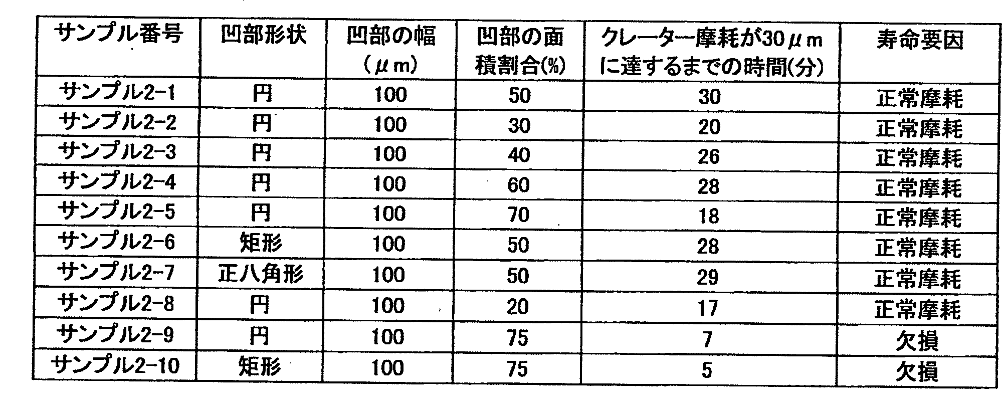
表2に示されるように、凹部の形状は、円、矩形または正八角形とした。凹部の幅(第1幅W1)は、100μmとした。第1長さL1は、100μmとした。凹部の深さ(第1深さD1)は、20μmとした。凹部の面積割合(つまり、凹部形成領域9に対する複数の凹部100の各々の総面積の比率)は、20%以上75%以下とした。
(評価方法)
上記の方法で作成した刃先交換型切削チップの一つを型番DCLNL2525-M12(住友電気工業株式会社製)のバイトにセットし、これを用いて旋削加工による耐摩耗性試験を行った。被削材は、純チタンASTM GR2(φ150~180mmの丸棒、4溝材)とした。切削速度(V)は、70m/minとした。送り量(f)は、0.2mm/rev.とした。切込量(ap)は、1.2mmとした。クーラントは、湿式(WET)とした。3次元形状測定機(alicona社製 infinite focus G5)で1分ごとにすくい面2におけるクレーター摩耗の深さを測定し、30μm以上の深さになったときの時間を測定した。
上記の方法で作成した刃先交換型切削チップの一つを型番DCLNL2525-M12(住友電気工業株式会社製)のバイトにセットし、これを用いて旋削加工による耐摩耗性試験を行った。被削材は、純チタンASTM GR2(φ150~180mmの丸棒、4溝材)とした。切削速度(V)は、70m/minとした。送り量(f)は、0.2mm/rev.とした。切込量(ap)は、1.2mmとした。クーラントは、湿式(WET)とした。3次元形状測定機(alicona社製 infinite focus G5)で1分ごとにすくい面2におけるクレーター摩耗の深さを測定し、30μm以上の深さになったときの時間を測定した。
(評価結果)
表2に示されるように、サンプル2-1~2-7に係る切削工具1においては、すくい面2におけるクレーター摩耗が30μmに達するまでの時間は、18分以上30分以下であった。一方、サンプル2-8~2-10に係る切削工具1においては、すくい面2におけるクレーター摩耗が30μmに達するまでの時間は、5分以上17分以下であった。またサンプル2-1~2-8に係る切削工具1においては、寿命要因は正常摩耗であった。一方、サンプル2-9~2-10に係る切削工具1においては、寿命要因はチップの欠損であった。以上の結果により、凹部の面積割合を30%以上70%以下とすることにより、すくい面2におけるクレーター摩耗が低減可能であることが確認された。
表2に示されるように、サンプル2-1~2-7に係る切削工具1においては、すくい面2におけるクレーター摩耗が30μmに達するまでの時間は、18分以上30分以下であった。一方、サンプル2-8~2-10に係る切削工具1においては、すくい面2におけるクレーター摩耗が30μmに達するまでの時間は、5分以上17分以下であった。またサンプル2-1~2-8に係る切削工具1においては、寿命要因は正常摩耗であった。一方、サンプル2-9~2-10に係る切削工具1においては、寿命要因はチップの欠損であった。以上の結果により、凹部の面積割合を30%以上70%以下とすることにより、すくい面2におけるクレーター摩耗が低減可能であることが確認された。
(サンプル準備)
まず、サンプル3-1~3-5に係る切削工具1を準備した。原料粉末として、原料粉末として0.27質量%のCr3C2粉末と、6.0質量%のCoと、93.73質量%のWCとバインダーを混練した。次に、射出成型によって刃先の一部を成形し、超硬合金の台金にロウ付けによって取り付けた。以上のようにして、CNMG120408N-EXの形状の切削工具1を作製した。
まず、サンプル3-1~3-5に係る切削工具1を準備した。原料粉末として、原料粉末として0.27質量%のCr3C2粉末と、6.0質量%のCoと、93.73質量%のWCとバインダーを混練した。次に、射出成型によって刃先の一部を成形し、超硬合金の台金にロウ付けによって取り付けた。以上のようにして、CNMG120408N-EXの形状の切削工具1を作製した。
表3に示されるように、凹部の形状は、円または矩形とした。凹部の幅(第1幅W1)は、100μmとした。第1長さL1は、25μm以上200μm以下とした。凹部の深さ(第1深さD1)は、20μmとした。凹部の面積割合(つまり、凹部形成領域9に対する複数の凹部100の各々の総面積の比率)は、50%とした。

(評価方法)
上記の方法で作成した刃先交換型切削チップの一つを型番DCLNL2525-M12(住友電気工業株式会社製)のバイトにセットし、これを用いて旋削加工による耐摩耗性試験を行った。被削材は、Ti-6Al-4V(φ150~180mmの丸棒、4溝材)とした。切削速度(V)は、70m/minとした。送り量(f)は、0.2mm/rev.とした。切込量(ap)は、1.2mmとした。クーラントは、湿式(WET)とした。3次元形状測定機(alicona社製 infinite focus G5)で1分ごとにすくい面2におけるクレーター摩耗の深さを測定し、30μm以上の深さになったときの時間を測定した。
上記の方法で作成した刃先交換型切削チップの一つを型番DCLNL2525-M12(住友電気工業株式会社製)のバイトにセットし、これを用いて旋削加工による耐摩耗性試験を行った。被削材は、Ti-6Al-4V(φ150~180mmの丸棒、4溝材)とした。切削速度(V)は、70m/minとした。送り量(f)は、0.2mm/rev.とした。切込量(ap)は、1.2mmとした。クーラントは、湿式(WET)とした。3次元形状測定機(alicona社製 infinite focus G5)で1分ごとにすくい面2におけるクレーター摩耗の深さを測定し、30μm以上の深さになったときの時間を測定した。
(評価結果)
表3に示されるように、サンプル3-1~3-4に係る切削工具1においては、すくい面2におけるクレーター摩耗が30μmに達するまでの時間は、18分以上26分以下であった。一方、サンプル3-5に係る切削工具1においては、すくい面2におけるクレーター摩耗が30μmに達するまでの時間は、5分であった。またサンプル3-1~3-4に係る切削工具1においては、寿命要因は正常摩耗であった。一方、サンプル3-5に係る切削工具1においては、寿命要因はチップの欠損であった。以上の結果により、第1長さL1を30μm以上とすることにより、すくい面2におけるクレーター摩耗が低減可能であることが確認された。
表3に示されるように、サンプル3-1~3-4に係る切削工具1においては、すくい面2におけるクレーター摩耗が30μmに達するまでの時間は、18分以上26分以下であった。一方、サンプル3-5に係る切削工具1においては、すくい面2におけるクレーター摩耗が30μmに達するまでの時間は、5分であった。またサンプル3-1~3-4に係る切削工具1においては、寿命要因は正常摩耗であった。一方、サンプル3-5に係る切削工具1においては、寿命要因はチップの欠損であった。以上の結果により、第1長さL1を30μm以上とすることにより、すくい面2におけるクレーター摩耗が低減可能であることが確認された。
(サンプル準備)
まず、サンプル4-1~4-5に係る切削工具1を準備した。原料粉末として、原料粉末として0.27質量%のCr3C2粉末と、6.0質量%のCoと、93.73質量%のWCとバインダーを混練した。次に、射出成型によって刃先の一部を成形し、超硬合金の台金にロウ付けによって取り付けた。以上のようにして、CNMG120408N-EXの形状の切削工具1を作製した。
まず、サンプル4-1~4-5に係る切削工具1を準備した。原料粉末として、原料粉末として0.27質量%のCr3C2粉末と、6.0質量%のCoと、93.73質量%のWCとバインダーを混練した。次に、射出成型によって刃先の一部を成形し、超硬合金の台金にロウ付けによって取り付けた。以上のようにして、CNMG120408N-EXの形状の切削工具1を作製した。
表4に示されるように、凹部の形状は、円または矩形とした。凹部の幅(第1幅W1)は、100μmとした。第1長さL1は、100μmとした。凹部の深さ(第1深さD1)は、5μm以上60μm以下とした。凹部の面積割合(つまり、凹部形成領域9に対する複数の凹部100の各々の総面積の比率)は、50%とした。

(評価方法)
上記の方法で作成した刃先交換型切削チップの一つを型番DCLNL2525-M12(住友電気工業株式会社製)のバイトにセットし、これを用いて旋削加工による耐欠損性試験を行った。被削材は、Ti-3Al-8V-6Cr-4Mo-4Zr(φ150~180mmの丸棒、4溝材)とした。切削速度(V)は、70m/minとした。送り量(f)は、0.2mm/rev.とした。切込量(ap)は、1.2mmとした。クーラントは、湿式(WET)とした。3次元形状測定機(alicona社製 infinite focus G5)で1分ごとにすくい面2におけるクレーター摩耗の深さを測定し、30μm以上の深さになったときの時間を測定した。
上記の方法で作成した刃先交換型切削チップの一つを型番DCLNL2525-M12(住友電気工業株式会社製)のバイトにセットし、これを用いて旋削加工による耐欠損性試験を行った。被削材は、Ti-3Al-8V-6Cr-4Mo-4Zr(φ150~180mmの丸棒、4溝材)とした。切削速度(V)は、70m/minとした。送り量(f)は、0.2mm/rev.とした。切込量(ap)は、1.2mmとした。クーラントは、湿式(WET)とした。3次元形状測定機(alicona社製 infinite focus G5)で1分ごとにすくい面2におけるクレーター摩耗の深さを測定し、30μm以上の深さになったときの時間を測定した。
(評価結果)
表4に示されるように、サンプル4-1~4-3および4-5に係る切削工具1においては、すくい面2におけるクレーター摩耗が30μmに達するまでの時間は、15分以上24分以下であった。一方、サンプル4-4に係る切削工具1においては、すくい面2におけるクレーター摩耗が30μmに達するまでの時間は、6分であった。またサンプル4-1~4-3および4-5に係る切削工具1においては、寿命要因は正常摩耗であった。一方、サンプル4-4に係る切削工具1においては、寿命要因はチップの欠損であった。以上の結果により、第1深さD1を50μm以下とすることにより、すくい面2におけるクレーター摩耗が低減可能であることが確認された。
表4に示されるように、サンプル4-1~4-3および4-5に係る切削工具1においては、すくい面2におけるクレーター摩耗が30μmに達するまでの時間は、15分以上24分以下であった。一方、サンプル4-4に係る切削工具1においては、すくい面2におけるクレーター摩耗が30μmに達するまでの時間は、6分であった。またサンプル4-1~4-3および4-5に係る切削工具1においては、寿命要因は正常摩耗であった。一方、サンプル4-4に係る切削工具1においては、寿命要因はチップの欠損であった。以上の結果により、第1深さD1を50μm以下とすることにより、すくい面2におけるクレーター摩耗が低減可能であることが確認された。
(サンプル準備)
まず、サンプル5-1~5-8に係る切削工具1を準備した。原料粉末として、原料粉末として0.27質量%のCr3C2粉末と、6.0質量%のCoと、93.73質量%のWCとバインダーを混練した。次に、射出成型によって刃先の一部を成形し、超硬合金の台金にロウ付けによって取り付けた。以上のようにして、CNMG120408N-EXの形状の切削工具1を作製した。
まず、サンプル5-1~5-8に係る切削工具1を準備した。原料粉末として、原料粉末として0.27質量%のCr3C2粉末と、6.0質量%のCoと、93.73質量%のWCとバインダーを混練した。次に、射出成型によって刃先の一部を成形し、超硬合金の台金にロウ付けによって取り付けた。以上のようにして、CNMG120408N-EXの形状の切削工具1を作製した。
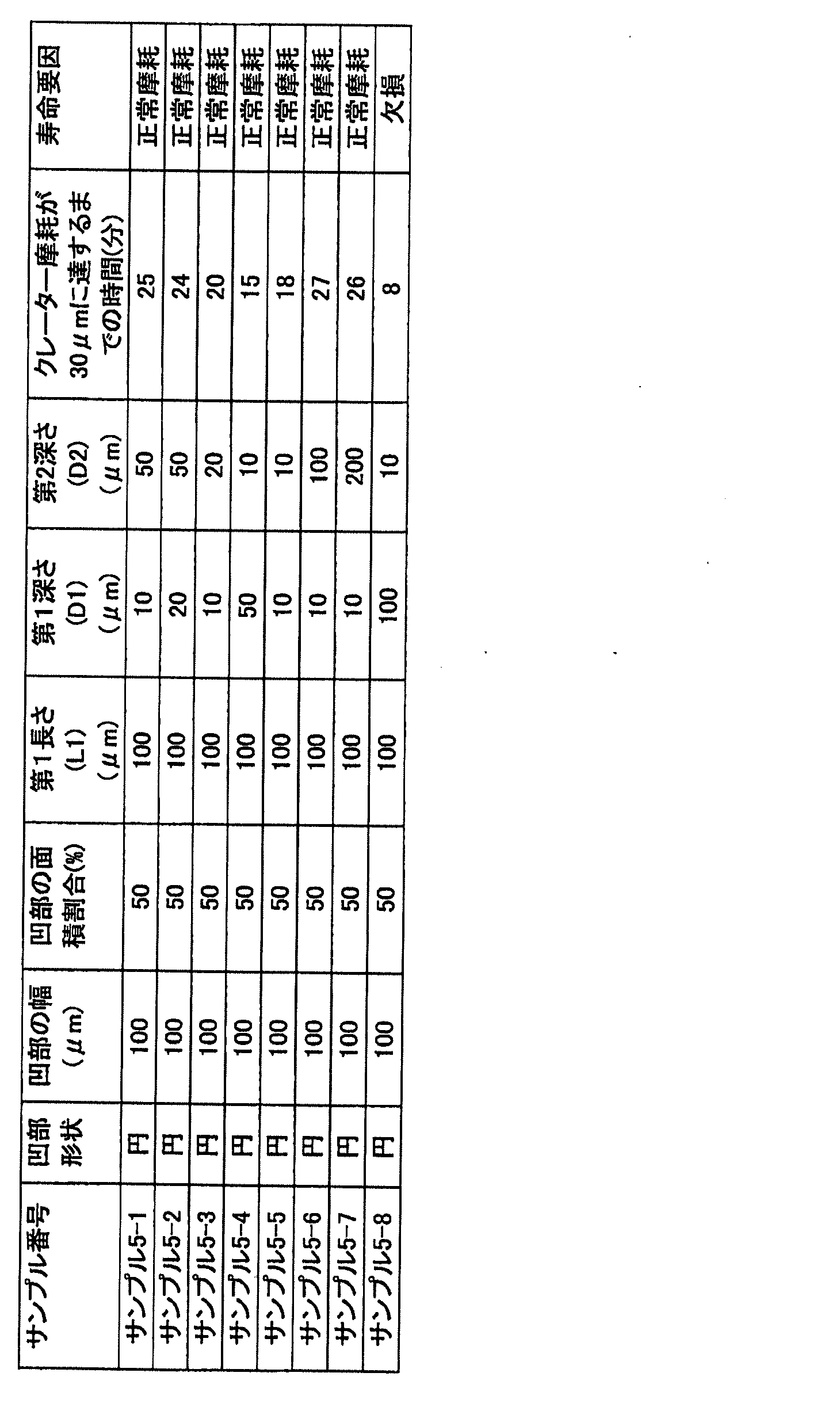
表5に示されるように、凹部の形状は、円とした。凹部の幅(第1幅W1)は、100μmとした。第1長さL1は、100μmとした。第1凹部10の深さ(第1深さD1)は、10μm以上100μm以下とした。第2凹部20の深さ(第2深さD2)は、10μm以上200μm以下とした。凹部の面積割合(つまり、凹部形成領域9に対する複数の凹部100の各々の総面積の比率)は、50%とした。
(評価方法)
上記の方法で作成した刃先交換型切削チップの一つを型番DCLNL2525-M12(住友電気工業株式会社製)のバイトにセットし、これを用いて旋削加工による耐欠損性試験を行った。被削材は、Ti-15V-3Cr-3Sn-3Al(φ150~180mmの丸棒、4溝材)とした。切削速度(V)は、70m/minとした。送り量(f)は、0.2mm/rev.とした。切込量(ap)は、1.2mmとした。クーラントは、湿式(WET)とした。3次元形状測定機(alicona社製 infinite focus G5)で1分ごとにすくい面2におけるクレーター摩耗の深さを測定し、30μm以上の深さになったときの時間を測定した。
上記の方法で作成した刃先交換型切削チップの一つを型番DCLNL2525-M12(住友電気工業株式会社製)のバイトにセットし、これを用いて旋削加工による耐欠損性試験を行った。被削材は、Ti-15V-3Cr-3Sn-3Al(φ150~180mmの丸棒、4溝材)とした。切削速度(V)は、70m/minとした。送り量(f)は、0.2mm/rev.とした。切込量(ap)は、1.2mmとした。クーラントは、湿式(WET)とした。3次元形状測定機(alicona社製 infinite focus G5)で1分ごとにすくい面2におけるクレーター摩耗の深さを測定し、30μm以上の深さになったときの時間を測定した。
(評価結果)
表5に示されるように、サンプル5-1~5-3および5-6~5-7に係る切削工具1においては、すくい面2におけるクレーター摩耗が30μmに達するまでの時間は、20分以上27分以下であった。一方、サンプル5-4~5-5および5-8に係る切削工具1においては、すくい面2におけるクレーター摩耗が30μmに達するまでの時間は、8分以上18分以下であった。またサンプル5-1~5-7に係る切削工具1においては、寿命要因は正常摩耗であった。一方、サンプル5-8に係る切削工具1においては、寿命要因はチップの欠損であった。以上の結果により、第2深さD2を第1深さD1よりも大きくすることにより、すくい面2におけるクレーター摩耗が低減可能であることが確認された。
表5に示されるように、サンプル5-1~5-3および5-6~5-7に係る切削工具1においては、すくい面2におけるクレーター摩耗が30μmに達するまでの時間は、20分以上27分以下であった。一方、サンプル5-4~5-5および5-8に係る切削工具1においては、すくい面2におけるクレーター摩耗が30μmに達するまでの時間は、8分以上18分以下であった。またサンプル5-1~5-7に係る切削工具1においては、寿命要因は正常摩耗であった。一方、サンプル5-8に係る切削工具1においては、寿命要因はチップの欠損であった。以上の結果により、第2深さD2を第1深さD1よりも大きくすることにより、すくい面2におけるクレーター摩耗が低減可能であることが確認された。
(サンプル準備)
まず、サンプル6-1~6-4に係る切削工具1を準備した。切削工具1の基材は、住友電工ハードメタル製の超硬合金製基材(形状:CNMG120408N-EX)とした。イオンプレーティング法を用いて3μmのTiAlNの被膜52を基材上に成膜した。被膜52が形成された基材をレーザーアブレーション装置に固定し、すくい面2にレーザー光を照射することにより凹部を形成した。レーザーとして、YAGレーザーを使用した。発振波長は、266nmとした。出力は、500Wとした。レーザー加工後の凹部の形状は、光学顕微鏡(キーエンス社製 デジタルマイクロスコープ VHX5000)を用いて計測した。
まず、サンプル6-1~6-4に係る切削工具1を準備した。切削工具1の基材は、住友電工ハードメタル製の超硬合金製基材(形状:CNMG120408N-EX)とした。イオンプレーティング法を用いて3μmのTiAlNの被膜52を基材上に成膜した。被膜52が形成された基材をレーザーアブレーション装置に固定し、すくい面2にレーザー光を照射することにより凹部を形成した。レーザーとして、YAGレーザーを使用した。発振波長は、266nmとした。出力は、500Wとした。レーザー加工後の凹部の形状は、光学顕微鏡(キーエンス社製 デジタルマイクロスコープ VHX5000)を用いて計測した。
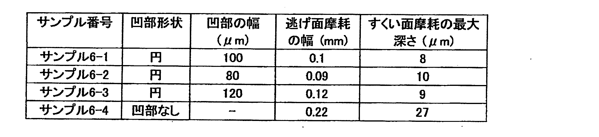
表6に示されるように、凹部の形状は、円とした。凹部の幅(第1幅W1)は、表6に記載の通りである。なお、サンプル6-4に係る切削工具1においては、すくい面2に凹部が設けられていない。第1長さL1は、100μmとした。凹部の深さ(第1深さD1)は、20μmとした。凹部の面積割合(つまり、凹部形成領域9に対する複数の凹部100の各々の総面積の比率)は、50%とした。
(評価方法)
上記の方法で作成した刃先交換型切削チップの一つを型番DCLNL2525-M12(住友電気工業株式会社製)のバイトにセットした。これを用いて鋼材の外径連続切削加工を行った。被削材は、SUS304(18Cr-8Ni鋼)(φ150~180mmの丸棒)とした。切削速度(V)は、100m/minとした。送り量(f)は、0.1mm/rev.とした。切込量(ap)は、1.2mmとした。クーラントは、湿式(WET)とした。上記の条件で90分間の切削加工を行った後に、3次元形状測定機(alicona社製 infinite focus G5)を用いて逃げ面摩耗の幅およびすくい面摩耗(クレーター摩耗)の最大深さを測定した。
上記の方法で作成した刃先交換型切削チップの一つを型番DCLNL2525-M12(住友電気工業株式会社製)のバイトにセットした。これを用いて鋼材の外径連続切削加工を行った。被削材は、SUS304(18Cr-8Ni鋼)(φ150~180mmの丸棒)とした。切削速度(V)は、100m/minとした。送り量(f)は、0.1mm/rev.とした。切込量(ap)は、1.2mmとした。クーラントは、湿式(WET)とした。上記の条件で90分間の切削加工を行った後に、3次元形状測定機(alicona社製 infinite focus G5)を用いて逃げ面摩耗の幅およびすくい面摩耗(クレーター摩耗)の最大深さを測定した。
(評価結果)
表6に示されるように、サンプル6-1~6-3に係る切削工具1においては、すくい面摩耗の最大深さは、8μm以上10μm以下であった。一方、サンプル6-4に係る切削工具1においては、すくい面摩耗の最大深さは、27μmであった。またサンプル6-1~6-3に係る切削工具1においては、逃げ面摩耗の幅は、0.09mm以上0.12mm以下であった。一方、サンプル6-4に係る切削工具1においては、逃げ面摩耗の幅は、0.22mmであった。以上の結果により、基材に被膜52を形成した切削工具1を用い、かつ被削材がSUS304の場合においても、逃げ面摩耗の幅およびすくい面摩耗の最大高さを低減可能であることが確認された。
表6に示されるように、サンプル6-1~6-3に係る切削工具1においては、すくい面摩耗の最大深さは、8μm以上10μm以下であった。一方、サンプル6-4に係る切削工具1においては、すくい面摩耗の最大深さは、27μmであった。またサンプル6-1~6-3に係る切削工具1においては、逃げ面摩耗の幅は、0.09mm以上0.12mm以下であった。一方、サンプル6-4に係る切削工具1においては、逃げ面摩耗の幅は、0.22mmであった。以上の結果により、基材に被膜52を形成した切削工具1を用い、かつ被削材がSUS304の場合においても、逃げ面摩耗の幅およびすくい面摩耗の最大高さを低減可能であることが確認された。
(サンプル準備)
まず、サンプル7-1~7-4に係る切削工具1を準備した。切削工具1の基材は、住友電工ハードメタル製の超硬合金製基材(形状:CNMG120408N-EX)とした。イオンプレーティング法を用いて3μmのTiAlNの被膜52を基材上に成膜した。被膜52が形成された基材をレーザーアブレーション装置に固定し、すくい面2にレーザー光を照射することにより凹部を形成した。レーザーとして、YAGレーザーを使用した。発振波長は、532nmとした。出力は、500Wとした。レーザー加工後の凹部の形状は、光学顕微鏡(キーエンス社製 デジタルマイクロスコープ VHX5000)を用いて計測した。
まず、サンプル7-1~7-4に係る切削工具1を準備した。切削工具1の基材は、住友電工ハードメタル製の超硬合金製基材(形状:CNMG120408N-EX)とした。イオンプレーティング法を用いて3μmのTiAlNの被膜52を基材上に成膜した。被膜52が形成された基材をレーザーアブレーション装置に固定し、すくい面2にレーザー光を照射することにより凹部を形成した。レーザーとして、YAGレーザーを使用した。発振波長は、532nmとした。出力は、500Wとした。レーザー加工後の凹部の形状は、光学顕微鏡(キーエンス社製 デジタルマイクロスコープ VHX5000)を用いて計測した。
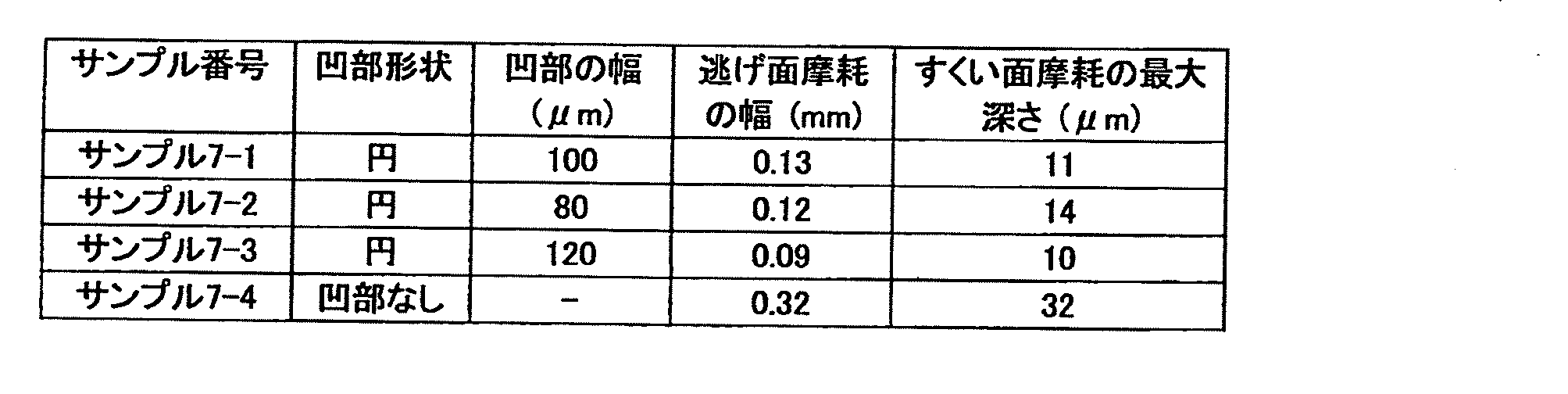
表7に示されるように、凹部の形状は、円とした。凹部の幅(第1幅W1)は、表7に記載の通りである。なお、サンプル7-4に係る切削工具1においては、すくい面2に凹部が設けられていない。第1長さL1は、100μmとした。凹部の深さ(第1深さD1)は、20μmとした。凹部の面積割合(つまり、凹部形成領域9に対する複数の凹部100の各々の総面積の比率)は、50%とした。
(評価方法)
上記の方法で作成した刃先交換型切削チップの一つを型番DCLNL2525-M12(住友電気工業株式会社製)のバイトにセットした。これを用いて鋼材の外径連続切削加工を行った。被削材は、インコネル(登録商標)718(溶態化・時効硬化処理材、ロックウェル硬度HRC(φ150~180mmの丸棒)とした。切削速度(V)は、50m/minとした。送り量(f)は、0.2mm/rev.とした。切込量(ap)は、0.8mmとした。クーラントは、湿式(WET)とした。上記の条件で30分間の切削加工を行った後に、3次元形状測定機(alicona社製 infinite focus G5)を用いて逃げ面摩耗の幅およびすくい面摩耗(クレーター摩耗)の最大深さを測定した。
上記の方法で作成した刃先交換型切削チップの一つを型番DCLNL2525-M12(住友電気工業株式会社製)のバイトにセットした。これを用いて鋼材の外径連続切削加工を行った。被削材は、インコネル(登録商標)718(溶態化・時効硬化処理材、ロックウェル硬度HRC(φ150~180mmの丸棒)とした。切削速度(V)は、50m/minとした。送り量(f)は、0.2mm/rev.とした。切込量(ap)は、0.8mmとした。クーラントは、湿式(WET)とした。上記の条件で30分間の切削加工を行った後に、3次元形状測定機(alicona社製 infinite focus G5)を用いて逃げ面摩耗の幅およびすくい面摩耗(クレーター摩耗)の最大深さを測定した。
(評価結果)
表7に示されるように、サンプル7-1~7-3に係る切削工具1においては、すくい面摩耗の最大深さは、10μm以上14μm以下であった。一方、サンプル7-4に係る切削工具1においては、すくい面摩耗の最大深さは、32μmであった。またサンプル7-1~7-3に係る切削工具1においては、逃げ面摩耗の幅は、0.09mm以上0.13mm以下であった。一方、サンプル7-4に係る切削工具1においては、逃げ面摩耗の幅は、0.32mmであった。以上の結果により、基材に被膜52を形成した切削工具1を用い、かつ被削材がインコネル(登録商標)の場合においても、逃げ面摩耗の幅およびすくい面摩耗の最大高さを低減可能であることが確認された。
表7に示されるように、サンプル7-1~7-3に係る切削工具1においては、すくい面摩耗の最大深さは、10μm以上14μm以下であった。一方、サンプル7-4に係る切削工具1においては、すくい面摩耗の最大深さは、32μmであった。またサンプル7-1~7-3に係る切削工具1においては、逃げ面摩耗の幅は、0.09mm以上0.13mm以下であった。一方、サンプル7-4に係る切削工具1においては、逃げ面摩耗の幅は、0.32mmであった。以上の結果により、基材に被膜52を形成した切削工具1を用い、かつ被削材がインコネル(登録商標)の場合においても、逃げ面摩耗の幅およびすくい面摩耗の最大高さを低減可能であることが確認された。
今回開示された実施形態および実施例はすべての点で例示であって、制限的なものではないと考えられるべきである。本発明の範囲は上記した説明ではなくて請求の範囲によって示され、請求の範囲と均等の意味、および範囲内でのすべての変更が含まれることが意図される。
1 切削工具、2 すくい面、3 逃げ面、4 切れ刃、4a 第1切刃部、4b コーナー切刃部、4c 第2切刃部、5 座面、6 取付孔、7 外側端部、8 内側端部、9 凹部形成領域、10 第1凹部、11 第1側面、12 第1底面、13 他方端部、14 一方端部、20 第2凹部、21 第2側面、22 第2底面、30 第3凹部、31 第3側面、32 第3底面、40 第4凹部、41 第4側面、42 第4底面、51 基材、52 被膜、100 複数の凹部、D1 第1深さ、D2 第2深さ、D3 第3深さ、G1 第5長さ、H 厚み、L1 第1長さ、L2 第2長さ、L3 第3長さ、L4 第4長さ、T1 第5幅、W1 第1幅、W2 第2幅、W3 第3幅、W4 第4幅、θ1 第1角度、θ2 第2角度。
Claims (9)
- すくい面と、
前記すくい面に連なる逃げ面と、
前記すくい面と反対側の座面とを備え、
前記すくい面と前記逃げ面との稜線は、切れ刃を構成し、
前記すくい面には、複数の凹部が設けられており、
前記座面に対して垂直な方向から見て、前記切れ刃の延在方向に対して垂直な方向において、前記複数の凹部の各々の幅は、60μmより大きく400μm以下である、切削工具。 - 前記座面に対して垂直な方向から見て、前記複数の凹部は、前記切れ刃の最も近くに位置する第1凹部を含む、請求項1に記載の切削工具。
- 前記座面に対して垂直な方向から見て、前記切れ刃と前記第1凹部との最短距離は、30μm以上である、請求項2に記載の切削工具。
- 前記座面に対して垂直な方向において、前記第1凹部の深さは、50μm以下である、請求項2または請求項3に記載の切削工具。
- 前記座面に対して垂直な方向から見て、前記複数の凹部は、前記切れ刃から最も遠くに位置する第2凹部を含む、請求項2から請求項4のいずれか1項に記載の切削工具。
- 前記座面に対して垂直な方向から見て、前記第1凹部から前記第2凹部までの凹部形成領域に対する前記複数の凹部の各々の総面積の比率は、30%以上70%以下である、請求項5に記載の切削工具。
- 前記座面に対して垂直な方向において、前記第2凹部の深さは、前記第1凹部の深さよりも大きい、請求項5または請求項6に記載の切削工具。
- 前記座面に対して垂直な方向から見て、前記複数の凹部の各々の少なくとも一部の形状は、円である、請求項1から請求項7のいずれか1項に記載の切削工具。
- 前記座面に対して垂直な方向から見て、前記複数の凹部の各々の少なくとも一部の形状は、矩形である、請求項1から請求項7のいずれか1項に記載の切削工具。
Priority Applications (1)
| Application Number | Priority Date | Filing Date | Title |
|---|---|---|---|
| JP2020572083A JPWO2020166145A1 (ja) | 2019-02-14 | 2019-11-05 |
Applications Claiming Priority (2)
| Application Number | Priority Date | Filing Date | Title |
|---|---|---|---|
| JP2019024125 | 2019-02-14 | ||
| JP2019-024125 | 2019-02-14 |
Publications (1)
| Publication Number | Publication Date |
|---|---|
| WO2020166145A1 true WO2020166145A1 (ja) | 2020-08-20 |
Family
ID=72044071
Family Applications (1)
| Application Number | Title | Priority Date | Filing Date |
|---|---|---|---|
| PCT/JP2019/043269 Ceased WO2020166145A1 (ja) | 2019-02-14 | 2019-11-05 | 切削工具 |
Country Status (2)
| Country | Link |
|---|---|
| JP (1) | JPWO2020166145A1 (ja) |
| WO (1) | WO2020166145A1 (ja) |
Cited By (1)
| Publication number | Priority date | Publication date | Assignee | Title |
|---|---|---|---|---|
| WO2025074852A1 (ja) * | 2023-10-05 | 2025-04-10 | 京セラ株式会社 | 切削インサート、切削工具、および切削加工物の製造方法 |
Citations (4)
| Publication number | Priority date | Publication date | Assignee | Title |
|---|---|---|---|---|
| JPS59193616U (ja) * | 1983-05-31 | 1984-12-22 | 三菱マテリアル株式会社 | 超硬ドリル |
| CN102189287A (zh) * | 2011-04-11 | 2011-09-21 | 山东大学 | 一种微织构自润滑钻头及其制备方法 |
| JP2012045635A (ja) * | 2010-08-24 | 2012-03-08 | Mitsubishi Materials Corp | 耐溶着性に優れた切削インサート |
| JP2013212572A (ja) * | 2012-03-07 | 2013-10-17 | Toyota Central R&D Labs Inc | 切削工具、その製造方法および切削品の製造方法 |
-
2019
- 2019-11-05 WO PCT/JP2019/043269 patent/WO2020166145A1/ja not_active Ceased
- 2019-11-05 JP JP2020572083A patent/JPWO2020166145A1/ja active Pending
Patent Citations (4)
| Publication number | Priority date | Publication date | Assignee | Title |
|---|---|---|---|---|
| JPS59193616U (ja) * | 1983-05-31 | 1984-12-22 | 三菱マテリアル株式会社 | 超硬ドリル |
| JP2012045635A (ja) * | 2010-08-24 | 2012-03-08 | Mitsubishi Materials Corp | 耐溶着性に優れた切削インサート |
| CN102189287A (zh) * | 2011-04-11 | 2011-09-21 | 山东大学 | 一种微织构自润滑钻头及其制备方法 |
| JP2013212572A (ja) * | 2012-03-07 | 2013-10-17 | Toyota Central R&D Labs Inc | 切削工具、その製造方法および切削品の製造方法 |
Cited By (1)
| Publication number | Priority date | Publication date | Assignee | Title |
|---|---|---|---|---|
| WO2025074852A1 (ja) * | 2023-10-05 | 2025-04-10 | 京セラ株式会社 | 切削インサート、切削工具、および切削加工物の製造方法 |
Also Published As
| Publication number | Publication date |
|---|---|
| JPWO2020166145A1 (ja) | 2020-08-20 |
Similar Documents
| Publication | Publication Date | Title |
|---|---|---|
| CN105563665B (zh) | 金刚石涂层刀具与制备方法及其在石墨高速加工中的应用 | |
| CN209288434U (zh) | 一种切削刃部、切削刀具及超声波刀具组件 | |
| CN116490308B (zh) | 金刚石工具 | |
| CN116551037B (zh) | 一种带有断屑槽的螺旋槽钻头 | |
| CN119794441A (zh) | 一种螺旋槽成形铣刀 | |
| JPWO2017146131A1 (ja) | 切削インサート | |
| JP6711830B2 (ja) | ドリル及びそれを用いた切削加工物の製造方法 | |
| CN113573830B (zh) | 刀片以及切削刀具 | |
| WO2020166145A1 (ja) | 切削工具 | |
| CN113573829B (zh) | 刀片以及切削刀具 | |
| CN101297061B (zh) | 表面包覆构件及其制造方法、以及切削工具 | |
| US12303987B2 (en) | Green body and cutting tool having helical superhard-material rake face | |
| JP2021530372A (ja) | 硬脆性難削材加工用ダイヤモンド切削工具 | |
| KR102880717B1 (ko) | 입방정 질화붕소 소결체 공구 | |
| JP4888659B2 (ja) | 刃先交換型切削チップ | |
| JP6756819B2 (ja) | 切削インサート及び切削工具 | |
| JP4014720B2 (ja) | ステップドリル | |
| CN220679467U (zh) | 一种带有断屑槽的螺旋槽钻头 | |
| KR102178428B1 (ko) | 회전 공구 | |
| JP5219618B2 (ja) | 切削工具 | |
| JP2004283951A (ja) | エンドミル | |
| CN221833394U (zh) | 一种前刀面带有沟槽的整体硬质合金铣刀 | |
| CN217621462U (zh) | 一种用于加工陶瓷材料的焊接式单刃pcd螺旋铣刀 | |
| JP2012000699A (ja) | 刃先交換型チップ | |
| CN206588434U (zh) | 一种小直径pcd直槽铰刀 |
Legal Events
| Date | Code | Title | Description |
|---|---|---|---|
| 121 | Ep: the epo has been informed by wipo that ep was designated in this application |
Ref document number: 19915210 Country of ref document: EP Kind code of ref document: A1 |
|
| ENP | Entry into the national phase |
Ref document number: 2020572083 Country of ref document: JP Kind code of ref document: A |
|
| NENP | Non-entry into the national phase |
Ref country code: DE |
|
| 122 | Ep: pct application non-entry in european phase |
Ref document number: 19915210 Country of ref document: EP Kind code of ref document: A1 |