WO2020166032A1 - 通信システム及び端末装置 - Google Patents
通信システム及び端末装置 Download PDFInfo
- Publication number
- WO2020166032A1 WO2020166032A1 PCT/JP2019/005436 JP2019005436W WO2020166032A1 WO 2020166032 A1 WO2020166032 A1 WO 2020166032A1 JP 2019005436 W JP2019005436 W JP 2019005436W WO 2020166032 A1 WO2020166032 A1 WO 2020166032A1
- Authority
- WO
- WIPO (PCT)
- Prior art keywords
- resource
- terminal device
- station
- unit
- information
- Prior art date
Links
Images


Classifications
-
- H—ELECTRICITY
- H04—ELECTRIC COMMUNICATION TECHNIQUE
- H04W—WIRELESS COMMUNICATION NETWORKS
- H04W72/00—Local resource management
- H04W72/02—Selection of wireless resources by user or terminal
-
- H—ELECTRICITY
- H04—ELECTRIC COMMUNICATION TECHNIQUE
- H04W—WIRELESS COMMUNICATION NETWORKS
- H04W28/00—Network traffic management; Network resource management
- H04W28/16—Central resource management; Negotiation of resources or communication parameters, e.g. negotiating bandwidth or QoS [Quality of Service]
- H04W28/26—Resource reservation
-
- H—ELECTRICITY
- H04—ELECTRIC COMMUNICATION TECHNIQUE
- H04W—WIRELESS COMMUNICATION NETWORKS
- H04W4/00—Services specially adapted for wireless communication networks; Facilities therefor
- H04W4/30—Services specially adapted for particular environments, situations or purposes
- H04W4/40—Services specially adapted for particular environments, situations or purposes for vehicles, e.g. vehicle-to-pedestrians [V2P]
- H04W4/46—Services specially adapted for particular environments, situations or purposes for vehicles, e.g. vehicle-to-pedestrians [V2P] for vehicle-to-vehicle communication [V2V]
-
- H—ELECTRICITY
- H04—ELECTRIC COMMUNICATION TECHNIQUE
- H04W—WIRELESS COMMUNICATION NETWORKS
- H04W72/00—Local resource management
- H04W72/12—Wireless traffic scheduling
- H04W72/1263—Mapping of traffic onto schedule, e.g. scheduled allocation or multiplexing of flows
-
- H—ELECTRICITY
- H04—ELECTRIC COMMUNICATION TECHNIQUE
- H04W—WIRELESS COMMUNICATION NETWORKS
- H04W72/00—Local resource management
- H04W72/30—Resource management for broadcast services
-
- H—ELECTRICITY
- H04—ELECTRIC COMMUNICATION TECHNIQUE
- H04W—WIRELESS COMMUNICATION NETWORKS
- H04W72/00—Local resource management
- H04W72/20—Control channels or signalling for resource management
-
- H—ELECTRICITY
- H04—ELECTRIC COMMUNICATION TECHNIQUE
- H04W—WIRELESS COMMUNICATION NETWORKS
- H04W92/00—Interfaces specially adapted for wireless communication networks
- H04W92/16—Interfaces between hierarchically similar devices
- H04W92/18—Interfaces between hierarchically similar devices between terminal devices
Definitions
- the present invention relates to a communication system and a terminal device.
- the traffic of mobile terminals such as smartphones and future phones accounts for the majority of network resources. Also, the traffic used by mobile terminals tends to continue to grow.
- 5G is classified into eMBB (Enhanced Mobile BroadBand), Massive MTC (Machine Type Communications), and URLLC (Ultra-Reliable and Low Latency Communication). It is intended to support many use cases.
- the 3GPP working group is also discussing V2X (Vehicle to Everything) communication.
- the 3GPP working group is also discussing D2D (Device to Device) communication. D2D communication is sometimes called side link communication.
- V2X is under study as an example of D2D communication.
- the V2X communication is, for example, communication using a side link channel, and includes, for example, V2V (Vehicle to Vehicle) communication, V2P (Vehicle to Pedestrian) communication, and V2I (Vehicle to Infrastructure) communication.
- V2V communication is communication between cars
- the V2P communication is communication between cars and pedestrians
- the V2I communication is communication between cars and road infrastructure such as signs.
- the regulations regarding V2X are described in Non-Patent Document 1, for example. In 4G V2X, feedback is not performed for data transmission, and data transmission is performed twice for one data.
- 4G V2X resource allocation methods include, for example, a method in which a mobile communication system performs centralized control and a method in which each terminal device that implements V2X autonomously controls.
- the method in which the mobile communication system performs centralized control is applicable when the terminal device implementing V2X is present in the coverage of the base station of the mobile communication system, and is also referred to as mode 1.
- the method in which each terminal device autonomously controls is applicable even if the terminal device is not in the coverage of the base station, and is also called mode 2. In mode 2, communication for resource allocation is not performed between the terminal device and the base station.
- a group is composed of a plurality of terminal devices, one of the plurality of terminal devices is a head station (or a scheduling station (scheduling UE)), and another terminal device other than the head station is As a member station, a method in which a head station autonomously allocates wireless resources to a plurality of member stations is under study.
- the terminal device joins the head station group as much as possible to become a member station, it needs resources for discovering the head station in the vicinity. Therefore, the terminal device needs resources to be used for discovering a neighboring head station, but it is conceivable that the resources for data discovery are insufficient due to the resources for discovery.
- the disclosed technology has been made in view of the above, and its purpose is to improve the use efficiency of resources.
- the communication system includes a first terminal device and a second terminal device that allocates resources used for data transmission to the first terminal device.
- the second terminal device has an allocation unit, a first transmission unit, and a release unit.
- the first terminal device has a selection unit and a second transmission unit.
- the allocation unit reserves resources in a resource group that can be allocated for data transmission.
- the first transmitter broadcasts a broadcast signal including resource reservation information.
- the selection unit receives the broadcast signal and selects a resource to be used from the reserved resources based on the resource reservation information in the broadcast signal.
- the second transmission unit transmits the feedback signal including the radio layer information to the second terminal device using the selected resource.
- the allocation unit receives a feedback signal including radio layer information from the first terminal device, and allocates a resource for data transmission to the first terminal device. When the release unit receives the feedback signal, the release unit releases the resource reservation used for the feedback signal.
- FIG. 1 is an explanatory diagram illustrating an example of the wireless communication system according to the first embodiment.
- FIG. 2 is a block diagram illustrating an example of the mobile station according to the first embodiment.
- FIG. 3A is a block diagram showing an example of functions of the V2V scheduler unit of the mobile station (head station).
- FIG. 3B is a block diagram showing an example of functions of the V2V scheduler unit of the mobile station (member station).
- FIG. 4 is an explanatory diagram showing an example of a resource pool.
- FIG. 5A is an explanatory diagram illustrating an example of the first orthogonal resource group.
- FIG. 5B is an explanatory diagram showing an example of a first orthogonal resource group when orthogonal resources are selected.
- FIG. 5A is an explanatory diagram illustrating an example of the first orthogonal resource group.
- FIG. 5C is an explanatory diagram illustrating an example of a first orthogonal resource group when releasing orthogonal resources.
- FIG. 5D is an explanatory diagram illustrating an example of the first orthogonal resource group when a member leaves.
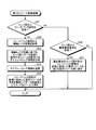
- FIG. 6 is a flowchart showing an example of the processing operation of the head station involved in the first notification signal transmission processing.
- FIG. 7 is a flowchart showing an example of the processing operation of the member stations involved in the first feedback processing.
- FIG. 8 is a flowchart showing an example of the processing operation of the head station involved in the first resource update processing.
- FIG. 9A is a block diagram illustrating an example of functions of the V2V scheduler unit of the mobile station (head station) according to the second embodiment.
- FIG. 9B is a block diagram showing an example of the function of the V2V scheduler unit of the mobile station (member station).
- FIG. 10 is a flowchart showing an example of the processing operation of the head station involved in the first notification processing.
- FIG. 11 is a flowchart showing an example of the processing operation of the member stations involved in the transmission processing.
- FIG. 12 is a flowchart showing an example of the processing operation of the head station involved in the scheduling processing.
- FIG. 13 is a flowchart showing an example of the processing operation of the head station related to the second notification processing of the third embodiment.
- FIG. 14A is a block diagram illustrating an example of functions of the V2V scheduler unit of the mobile station (head station) according to the fourth embodiment.
- FIG. 14B is a block diagram showing an example of the functions of the V2V scheduler unit of the mobile station (member station).
- FIG. 15A is an explanatory diagram illustrating an example of the second orthogonal resource group.
- FIG. 15B is an explanatory diagram illustrating an example of the second orthogonal resource group when the orthogonal subset is selected.
- FIG. 15C is an explanatory diagram showing an example of the second orthogonal resource group when a member leaves.
- FIG. 16 is a flowchart showing an example of the processing operation of the head station involved in the second search information transmission processing.
- FIG. 17 is a flowchart showing an example of the processing operation of the member stations involved in the second feedback processing.
- FIG. 16 is a flowchart showing an example of the processing operation of the head station involved in the second search information transmission processing.
- FIG. 17 is a flowchart showing an example of the processing operation of the member stations involved in the second feedback processing.
- FIG. 16 is a flowchart showing an example of
- FIG. 18 is a flowchart showing an example of the processing operation of the head station involved in the second resource update processing.
- FIG. 19A is a block diagram illustrating an example of functions of the V2V scheduler unit of the mobile station (member station) according to the fifth embodiment.
- FIG. 19B is a block diagram showing an example of functions of the V2V scheduler unit of the mobile station (head station).
- FIG. 20 is a flowchart showing an example of the processing operation of the member stations involved in the joining processing.
- FIG. 21 is a flowchart showing an example of the processing operation of the head station involved in the registration processing.
- FIG. 1 is an explanatory diagram illustrating an example of the wireless communication system 1 according to the first embodiment.
- the wireless communication system 1 shown in FIG. 1 has a plurality of mobile stations (UE:User Equipment) 2 and a base station (BS:Base Station) 3.
- UE User Equipment
- BS Base Station
- LTE-V2V Long Term Evolution-Vehicle to Vehicle
- the V2V communication resource allocation methods include, for example, mode 1 and mode 2.
- the wireless communication system 1A used in the mode 1 can be applied when the base station 3 centrally controls resources and the mobile station 2 performing V2V communication is in the coverage area of the base station 3. Further, in the wireless communication system 1B used in the mode 2, each mobile station 2 that performs V2V communication is autonomously controlled, and the mobile station 2 can be applied even if the mobile station 2 is not in the coverage of the base station 3.
- a group may be formed by a plurality of mobile stations 2 traveling in a vehicle platoon.
- the vehicle platooning is a service in which, for example, a plurality of vehicles equipped with the mobile station 2 form a platoon and automatically travel.
- one mobile station 2 in the group is a head station 2A
- the other mobile stations 2 other than the head station 2A are member stations 2B.
- the head station 2A and the member station 2B have a master-slave relationship.
- the head station 2A executes a scheduling operation of allocating resources used for data transmission of the other member station 2B.
- Each mobile station 2 in the wireless communication system 1B used in mode 2 senses the frequency band used for V2V communication. Specifically, the mobile station 2 receives the SCI (Side link Control Channel) of the entire frequency band used for V2V communication in a predetermined sensing period and measures the received power of the corresponding sub-channel. Then, the mobile station 2 determines whether or not another mobile station 2 is transmitting a signal in each subframe and subchannel. When the mobile station 2 detects a transmission request for data transmission, the mobile station 2 excludes a resource that is likely to be used by another mobile station 2 based on the sensing result, and selects an empty resource to be allocated for data transmission.
- SCI System link Control Channel
- the mobile station 2 sets a resource that is likely to be used by another mobile station 2 as a reserved resource in the selection window based on the sensing result. Then, the mobile station 2 selects a free resource other than the reserved resource in the selection window and allocates data transmission to the selected free resource.
- mode 2a is a mode in which the mobile station 2 autonomously selects the side link resource for transmission.
- the mode 2d is a mode in which the mobile station 2 schedules side link transmission of another mobile station 2.
- the mode 2d group has a plurality of member stations 2B and a head station 2A that autonomously allocates resources to the member stations 2B.
- the head station 2A uses side link resources instead of the base station 3. Assign to member station 2B.
- FIG. 2 is a block diagram showing an example of the mobile station 2 of the first embodiment.
- the mobile station 2 shown in FIG. 2 includes a cellular antenna 11, a cellular reception unit 12, a CP (Cyclic Prefix) removal unit 13, an FFT (Fast Fourier Transform) unit 14, a decoding unit 15, and a scheduler. And part 16. Furthermore, the mobile station 2 includes a data generation unit 17, a data encoding unit 18, an IFFT (Inverse Fast Fourier Transform) unit 19, a CP addition unit 20, and a cellular transmission unit 21.
- IFFT Inverse Fast Fourier Transform
- the mobile station 2 includes a V2V antenna 22, a V2V receiving unit 23, a V2V control decoding unit 24, a V2V data decoding unit 25, a V2V scheduler unit 27, and a resource pool 28.
- the mobile station 2 has a V2V control generation unit 29, a V2V data generation unit 30, and a V2V transmission unit 32.
- the cellular antenna 11 transmits/receives a radio signal of a radio carrier used for the mode 1 radio communication system 1A, for example.
- the cellular reception unit 12 receives a radio signal through the cellular antenna 11, and performs radio reception processing such as down conversion and A/D conversion on the received signal.
- CP removing section 13 removes the CP added to the received signal in symbol units. Then, CP removing section 13 outputs the received signal after CP removal to FFT section 14.
- the FFT unit 14 performs a fast Fourier transform on the reception signal output from the CP removal unit 13, and converts the reception signal in the time domain into a reception signal in the frequency domain.
- the received signal includes data transmitted from the base station 3 and control signals.
- the decoding unit 15 demodulates and decodes data from the received signal in the frequency domain after being converted by the FFT unit 14.
- the decoding unit 15 demodulates and decodes the control signal from the converted reception signal in the frequency domain.
- the scheduler unit 16 executes scheduling for allocating radio resources to data transmitted/received to/from the base station 3. Specifically, the scheduler unit 16 allocates radio resources to the data transmitted by each mobile station 2, and executes uplink scheduling from the mobile station 2 to the base station 3. The scheduler unit 16 executes downlink scheduling from the base station 3 to the mobile station 2.
- the data generation unit 17 generates data to be transmitted to the base station 3.
- the data encoding unit 18 encodes and modulates the generated data, and outputs the modulated data to the IFFT unit 19.
- the IFFT unit 19 performs inverse fast Fourier transform on the data output from the data generation unit 17, and converts the transmission signal in the frequency domain into a transmission signal in the time domain. Then, IFFT section 19 outputs the transmission signal in the time domain to CP adding section 20.
- CP adding section 20 adds a CP to the transmission signal output from IFFT section 19 in symbol units. Then, the CP adding unit 20 outputs the transmission signal to which the CP is added to the cellular transmitting unit 21.
- the cellular transmitter 21 performs wireless transmission processing such as D/A conversion and up-conversion on the transmission signal, and transmits the wireless signal through the cellular antenna 11.
- the V2V antenna 22 transmits and receives a wireless signal of V2V communication used for the wireless communication system 1B of mode 2, for example.
- the V2V receiving unit 23 receives a wireless signal through the V2V antenna 22, and performs a wireless receiving process such as down conversion and A/D conversion on the received signal.
- the V2V control decoding unit 24 decodes the V2V control signal included in the reception signal subjected to the reception processing by the V2V reception unit 23.
- the V2V control signal is control information in the subchannel in the PSSCH in the received signal.
- the V2V data decoding unit 25 decodes the V2V data signal included in the reception signal processed by the V2V reception unit 23.
- the V2V data signal is the data in the subchannel in the PSSCH in the received signal.
- the V2V scheduler unit 27 executes scheduling for allocating resources used for V2V communication to data transmitted/received to/from the V2V mobile station 2.
- the resource pool 28 manages resources used for V2V communication, such as a mode 2a pool 28A and a mode 2d pool 28B described later.
- the V2V control generation unit 29 generates a V2V control signal to be transmitted to the mobile station 2 of the transmission destination, for example, control information of the subchannel.
- the V2V data generation unit 30 generates a V2V data signal to be transmitted to the mobile station 2 of the transmission destination, for example, subchannel data.
- the V2V transmission unit 32 wirelessly performs D/A conversion and up-conversion on the V2V transmission signal including the V2V control signal generated by the V2V control generation unit 29 and the V2V data signal generated by the V2V data generation unit 30. Execute the sending process. Then, the V2V transmission unit 32 transmits the V2V wireless signal after the wireless transmission process is executed through the V2V antenna 22.
- FIG. 3A is a block diagram showing an example of the function of the V2V scheduler unit 27 of the mobile station 2 (head station 2A), and FIG. 3B is a block showing an example of the function of the V2V scheduler unit 27 of the mobile station 2 (member station 2B). It is a figure.
- the V2V scheduler unit 27 of the head station 2A shown in FIG. 3A reads a program stored in a ROM (Read Only Memory) (not shown) and executes the read program to, for example, the first transmission unit 41. , Performs the functions of the allocation unit 42 and the release unit 43.
- ROM Read Only Memory
- the first transmission unit 41 broadcast-transmits a broadcast signal including a first orthogonal resource group 100 including orthogonal resources from a part of the mode 2d pool 28B that can be assigned to data transmission.
- the orthogonal resource is a resource in an orthogonal state for returning a feedback signal when the user wants to join the group.
- the feedback signal is a reply signal for requesting the head station 2A to join the group.
- the allocating unit 42 allocates the data transmission resource to the member station 2B related to the wireless layer information, based on the wireless layer information in the feedback signal.
- the allocating unit 42 After recognizing the QoS information in the radio layer information, the allocating unit 42 allocates a resource for data transmission while considering, for example, two different traffic types, synchronous or asynchronous. Further, when receiving the feedback signal, the releasing unit 43 releases the reservation of the orthogonal resource used for the feedback signal and returns the orthogonal resource to the mode 2d pool 28B for data transmission.
- the V2V scheduler unit 27 of the member station 2B illustrated in FIG. 3B reads a program stored in a ROM (not shown) and executes the read program, for example, the selection unit 51 and the second transmission unit. It performs the function of 52.
- the selection unit 51 selects the orthogonal resource in the first orthogonal resource group 100 in the broadcast signal.
- the selection unit 51 designates one orthogonal resource from the first orthogonal resource group 100 and executes the short-term sensing process on the designated orthogonal resource.
- the short-term sensing process does not sense all the orthogonal resources, but executes the sensing process by designating the next candidate unspecified orthogonal resource when the orthogonal resource is in use, based on the sensing result. Further, the selection unit 51 selects the empty orthogonal resource when the orthogonal resource is empty based on the sensing result.
- the second transmitter 52 reserves the selected orthogonal resource and transmits a feedback signal including the radio layer information of the own station to the head station 2A.
- FIG. 4 is an explanatory diagram illustrating an example of the resource pool 28 according to the first embodiment.
- the resource pool 28 includes a mode 2a pool 28A that manages mode 2a resources and a mode 2d pool 28B that manages mode 2d resources.
- the mode 2a pool 28A is a resource pool that is self-assigned by the local station.
- the mode 2d pool 28B is a resource pool assigned to the member station 2B by the head station 2A.
- FIG. 5A is an explanatory diagram showing an example of the first orthogonal resource group 100.
- the head station 2A generates a first orthogonal resource group 100 including some orthogonal resources R1 to R6 of the mode 2d pool 28B.
- the first orthogonal resource group 100 includes six orthogonal resources R1 to R6, and the orthogonal resources R1 to R6 are in a reservable empty state.
- the orthogonal resource is a resource used for transmitting a feedback signal for a broadcast signal.
- the first orthogonal resource group 100 stores, for example, six orthogonal resources R1 to R6.
- the head station 2A broadcasts a broadcast signal including the first orthogonal resource group 100 by SCI using the mode 2a pool 28A.
- the mobile station 2 participates in the group of the head station 2A as the member station 2B, the mobile station 2 receives the notification signal from the head station 2A and acquires the first orthogonal resource group 100 in the received notification signal.
- FIG. 5B is an explanatory diagram showing an example of the first orthogonal resource group 100 when orthogonal resources are selected.
- the mobile station 2 specifies one orthogonal resource in the first orthogonal resource group 100, performs a short-term sensing process on the specified orthogonal resource, and determines whether or not the orthogonal resource is empty. judge. When the orthogonal resource is empty, the mobile station 2 selects the empty orthogonal resource. Further, when the orthogonal resource is not empty, the mobile station 2 specifies an unspecified orthogonal resource in the first orthogonal resource group 100 and executes the short-term sensing process on the specified orthogonal resource.
- the mobile station 2 selects (reserves) the empty orthogonal resource and then uses the empty orthogonal resource to transmit a feedback signal for the broadcast signal to the head station 2A.
- the orthogonal resources R1 to R3 have been reserved and the orthogonal resources R4 to R6 can be reserved for feedback signal transmission.
- FIG. 5C is an explanatory diagram showing an example of the first orthogonal resource group 100 when releasing orthogonal resources.
- the head station 2A receives the feedback signal from the mobile station 2 using the orthogonal resource, the head station 2A registers the mobile station 2 as the member station 2B. Further, the head station 2A releases the reservation of the orthogonal resource used for receiving the feedback signal and returns the orthogonal resource to the mode 2d pool 28B for data transmission. That is, when the head station 2A receives the feedback signal using the three orthogonal resources R1 to R3 among the plurality of orthogonal resources R1 to R6, the head station 2A releases the orthogonal resources R1 to R3 and enters the mode 2d pool 28B. return. Therefore, in the first orthogonal resource group 100 shown in FIG. 5C, the orthogonal resources R1 to R3 are returned to the mode 2d pool 28B for data transmission, and the orthogonal resources R4 to R6 are reserved for feedback signal transmission.
- FIG. 5D is an explanatory diagram showing an example of the first orthogonal resource group 100 when a member leaves.
- the member station 2B transmits a leave request signal to the head station 2A.
- the head station 2A receives the leave request signal from the member station 2B, only the orthogonal resource R2 used by the member station 2B for the feedback signal is returned to the first orthogonal resource group 100.
- the first orthogonal resource group 100 shown in FIG. 5D is in a state where the orthogonal resources R2 and R4 to R6 can be reserved for feedback signal transmission.
- FIG. 6 is a flowchart showing an example of the processing operation of the head station 2A related to the first notification signal transmission processing.
- the first transmission unit 41 in the head station 2A generates a part of the mode 2d pool 28B as the first orthogonal resource group 100, and temporarily transmits the feedback signal to the first orthogonal resource group 100. Reserve as credit (step S11).
- the 1st transmission part 41 broadcast-transmits the alerting
- the head station 2A sets a part of the mode 2d pool 28B as a first orthogonal resource group 100 of orthogonal resources, and broadcast-transmits a broadcast signal including the first orthogonal resource group 100.
- the head station 2A can transmit the orthogonal resource for feedback signal transmission required for member participation to the neighboring mobile station 2.
- the mobile station 2 that desires the member station 2B can recognize the orthogonal resource for transmitting the feedback signal.
- FIG. 7 is a flowchart showing an example of the processing operation of the member station 2B involved in the first feedback processing. For convenience of explanation, the processing operation of executing the first feedback process as the member station 2B will be described.
- the mobile station 2 desiring to participate in the group executes the first feedback process and then executes the first feedback process.
- the selection unit 51 in the member station 2B determines whether or not a notification signal has been received from the head station 2A using the mode 2a pool 28A (step S21). When the notification signal is received (Yes at Step S21), the selection unit 51 acquires the first orthogonal resource group 100 from the notification signal (Step S22).
- the selection unit 51 After acquiring the first orthogonal resource group 100, the selection unit 51 specifies an unspecified orthogonal resource from the acquired first orthogonal resource group 100 (step S23). After selecting the unspecified orthogonal resource, the selection unit 51 executes the short-term sensing process for the specified orthogonal resource (step S24). The selection unit 51 determines whether or not the designated orthogonal resource is empty based on the sensing result (step S25).
- the selection unit 51 selects an empty orthogonal resource (Step S26). Further, the second transmitter 52 in the member station 2B selects a free orthogonal resource, then generates the wireless layer information of the own station, and generates a feedback signal including the wireless layer information (step S27).
- the radio layer information is, for example, mobile station performance information, layer 2 identification information (ID), buffer status information (currently used data size), QoS information (synchronous or asynchronous communication, etc.), and the like.
- the second transmitter 52 uses the mode 2d pool 28B to transmit the feedback signal to the head station 2A using the selected orthogonal resource (step S28).
- the member station 2B determines whether or not the scheduling information is received from the head station 2A (step S29). When the member station 2B receives the scheduling information (Yes at Step S29), the member station 2B transmits data by using the allocation resource in the scheduling information (Step S30), and ends the processing operation illustrated in FIG. 7.
- the member station 2B does not receive the notification signal from the head station 2A (No at Step S21), the processing operation shown in FIG. 7 is ended. If the designated orthogonal resource is not empty (No at Step S25), the member station 2B proceeds to Step S23 to designate the unspecified orthogonal resource. Further, when the member station 2B does not receive the scheduling information from the head station 2A (No at step S29), the member station 2B proceeds to the processing operation of step S29 to determine whether to receive the scheduling information.
- the mobile station 2 When the mobile station 2 receives the broadcast signal from the head station 2A, the mobile station 2 acquires the first orthogonal resource group 100 from the broadcast signal, the first orthogonal resource group 100 designates an orthogonal resource, and the designated orthogonal resource is specified. A short-term sensing process is executed for. Based on the sensing result, the mobile station 2 transmits a feedback signal including the radio layer information of the own station to the head station 2A when the designated orthogonal resource is empty, using the empty orthogonal resource. As a result, the mobile station 2 uses the orthogonal resource in the first orthogonal resource group 100 to transmit the feedback signal to the head station 2A, and thus can participate in the group as the member station 2B.
- FIG. 8 is a flowchart showing an example of the processing operation of the head station 2A related to the first resource update processing.
- the head station 2A determines whether or not a feedback signal has been received from the member station 2B (step S31).
- the head station 2A acquires the wireless layer information from the feedback signal (Step S32).
- the head station 2A After acquiring the wireless layer information, the head station 2A identifies the mobile station 2 (member station 2B) that has transmitted the feedback signal based on the wireless layer information. Further, the head station 2A generates scheduling information for allocating the resource used for data transmission of the member station 2B of the wireless layer information (step S33). The head station 2A transmits the generated scheduling information to the member station 2B (step S34). After receiving the feedback signal, the release unit 43 in the head station 2A releases the reservation of the orthogonal resource used for receiving the feedback signal and returns the released orthogonal resource to the mode 2d pool 28B for data transmission (step S35). Then, the head station 2A ends the processing operation shown in FIG.
- the head station 2A determines whether or not the departure request signal is received from the member station 2B (step S36).
- the head station 2A receives the leave request signal (Yes in step S36)
- the head station 2A returns the orthogonal resource used by the member station 2B requesting the leave to receive the previous feedback signal to the first orthogonal resource group 100 (step S37). , And ends the processing operation shown in FIG.
- the processing operation illustrated in FIG. 8 ends.
- the head station 2A When the head station 2A receives the feedback signal using the orthogonal resource, the head station 2A returns the orthogonal resource for transmitting the feedback signal to the mode 2d pool for transmitting data. As a result, the utilization efficiency of resources can be improved.
- the head station 2A When the head station 2A receives the leave request signal from the member station 2B, the head station 2A returns the orthogonal resources used by the leave requesting member station 2B to receive the feedback signal to the first orthogonal resource group 100. As a result, by returning the orthogonal resource to the first orthogonal resource, the utilization efficiency of the orthogonal resource for feedback signal transmission can be improved.
- Example 1 the resource is temporarily reserved and dynamically updated to discover the side link, so that the resource utilization efficiency is increased.
- the number of orthogonal resources is set to 6, but the number is not limited to 6. Instead, it can be changed as appropriate according to the number of groups that can participate.
- the six orthogonal resources can be expressed by 3 bits and can be expressed by using 3 bits in the SCI format.
- the head station 2A may increase the number of resources in the first orthogonal resource group 100 at the next timing. Further, when the head station 2A reduces the number of groups that can participate in the group, the number of resources in the first orthogonal resource group 100 may be reduced at the next timing, and the number can be changed as appropriate.
- the first orthogonal resource group 100 is composed of a plurality of resources has been illustrated, but it may be composed of a plurality of subsets composed of a plurality of resources and can be appropriately changed.
- the first embodiment is an example in which the first orthogonal resource group is configured, the resource group/subset that is not orthogonal may be configured, for example.
- FIG. 9A is a block diagram showing an example of the function of the V2V scheduler unit 27 of the mobile station 2 (head station 2A), and FIG. 9B is a block showing an example of the function of the V2V scheduler unit 27 of the mobile station 2 (member station 2B). It is a figure.
- the V2V scheduler unit 27 of the head station 2A shown in FIG. 9A reads a program stored in a ROM (not shown) and executes the read program, for example, the third transmission unit 41A and the second acquisition unit.
- the functions of the unit 44A and the allocation unit 42A are executed.
- the third acquisition unit 44A receives the scheduling request signal from the member station 2B, the second acquisition unit 44A acquires the wireless layer information from the scheduling request signal.
- the assigning unit 42A refers to the acquired wireless layer information and assigns the resource for data transmission to the member station 2B.
- the V2V scheduler unit 27 of the member station 2B illustrated in FIG. 9B reads a program stored in a ROM (not shown) and executes the read program, for example, the first acquisition unit 51A and the fourth acquisition unit 51A. And executes the function of the transmission unit 52A.
- the first acquisition unit 51A receives the notification signal from the head station 2A
- the first acquisition unit 51A acquires the resource pool information in the notification signal.
- the fourth transmitter 52A transmits a scheduling request signal including the radio layer information of the own station to the head station 2A based on the acquired resource pool information.
- FIG. 10 is a flowchart showing an example of the processing operation of the head station 2A related to the first notification processing.
- the head station 2A acquires an allocatable resource pool from the base station 3 (step S41). After acquiring the allocatable resource pool from the base station 3, the head station 2A executes a sensing process for the resource pool (step S42). After executing the sensing process for the resource pool, the head station 2A selects a resource (or a plurality of resources/a plurality of subsets) used by the head station 2A based on the sensing result (step S43).
- the head station 2A outside the range of the base station 3 generates and reserves the resource pool information using the mode 2d pool 28B (step S44), and broadcasts a notification signal including the resource pool information by SCI (step S45). , And ends the processing operation shown in FIG.
- the head station 2A uses the mode 2d pool 28B to generate resource pool information, and broadcasts a notification signal including the resource pool information. As a result, when the member station 2B receives the notification signal, the member station 2B can recognize the assignable resource pool information.
- FIG. 11 is a flowchart showing an example of the processing operation of the member station 2B involved in the transmission processing.
- the first acquisition unit 51A in the member station 2B determines whether or not a notification signal has been received from the head station 2A (step S51).
- the notification signal is received from the head station 2A (Yes at Step S51)
- the first acquisition unit 51A acquires the ID of the head station 2A and the resource pool information from the notification signal (Step S52).
- the member station 2B can recognize the head station 2A that manages the resource pool information.
- the fourth transmitter 52A in the member station 2B determines whether or not there is transmission data (step S53). When there is transmission data (Yes at Step S53), the fourth transmitter 52A generates a scheduling request signal including the wireless layer information of the own station (Step S54).
- the fourth transmitter 52A transmits the scheduling request signal to the head station 2A by SCI based on the resource pool information (step S55).
- the member station 2B determines whether or not the scheduling information is received from the head station 2A (step S56). When the member station 2B receives the scheduling information (Yes at Step S56), the member station 2B transmits data by using the allocation resource in the scheduling information (Step S57), and ends the processing operation illustrated in FIG.
- the processing operation shown in FIG. 11 is ended.
- the member station 2B ends the processing operation shown in FIG. If the member station 2B does not receive the scheduling information from the head station 2A (No at Step S56), the member station 2B proceeds to Step S56 to determine whether the scheduling information is received.
- the member station 2B transmits a scheduling request signal to the head station 2A when there is transmission data.
- the head station 2A can allocate resources to the member station 2B that has issued the scheduling request signal via SCI.
- FIG. 12 is a flowchart showing an example of the processing operation of the head station 2A related to the scheduling processing.
- the second acquisition unit 44A in the head station 2A outside the coverage area of the base station 3 determines whether or not the scheduling request signal is received from the member station 2B (step S61).
- the second acquisition unit 44A acquires the wireless layer information from the scheduling request signal (Step S62).
- the allocation unit 42A in the head station 2A After acquiring the wireless layer information, the allocation unit 42A in the head station 2A generates scheduling information for allocating the resource used for data transmission to the member station 2B of the wireless layer information (step S63). The allocation unit 42A transmits the generated scheduling information to the member station 2B (step S64), and ends the processing operation illustrated in FIG.
- the head station 2A When the head station 2A receives the scheduling request signal from the member station 2B, the head station 2A acquires the radio layer information in the scheduling request signal, and provides the member station 2B of the radio layer information with the scheduling information of the resource used for data transmission to the member station 2B. Send to. As a result, the member station 2B can realize data transmission based on the resource information in the scheduling information from the head station 2A.
- the head station 2A selects a resource to be used for initial transmission, reserves a resource to be used for retransmission, and selects a resource to be used for feedback of ACK/NACK from the receiving side member station 2B.
- the layer 2 ID is used for ACK/NACK of HARQ (Hybrid Automatic Retransmission Request).
- the transmitting member station 2B can decipher the HARQ. That is, the head station 2A broadcasts, by SCI, scheduling information that allocates each resource of the initial transmission, retransmission, and ACK/NACK feedback to the transmitting side member station 2B and the receiving side member station 2B.
- the head station 2A in the second embodiment described above exemplifies a case where the free resources used for data transmission are allocated to the member station 2B based on the resource pool information permitted by the base station 3.
- the sensing process for the resource in the resource pool may be executed based on the resource pool information in the notification signal.
- each member station 2B may select an unused free resource to be used for ACK/NACK feedback or data transmission based on the sensing result, which can be appropriately changed.
- the head station 2A senses each resource or subset in the allocatable resource group managed by the base station. Further, the head station 2A selects one resource or subset based on the sensing result. Further, the head station 2A broadcasts a broadcast signal including resource pool information that identifies each resource in the resource group that can be allocated for data transmission, using the selected resource or subset.
- the member station 2B receives the broadcast signal, the member station 2B acquires the resource pool information in the broadcast signal. The member station 2B allocates resources for data transmission based on the acquired resource pool information. In this case, the member station 2B does not need to transmit the scheduling request for resource allocation to the head station 2A.
- the resources allocated to the data transmission are illustrated, but the resources are not limited to the resources, and a subset may be used and can be appropriately changed.
- the wireless communication system 1B of the third embodiment when the head station 2A that has acquired the resource pool information from the base station 3 operates within the base station 3 will be described.
- the same components as those in the second embodiment are designated by the same reference numerals, and the description of the overlapping components and operations will be omitted.
- FIG. 13 is a flowchart showing an example of the processing operation of the head station 2A related to the second notification processing of the third embodiment.
- the head station 2A transmits a head request signal to the base station 3 (step S71). After transmitting the head request signal, the head station 2A acquires an allocatable subset from the base station 3 (step S72). The head station 2A creates the resource pool information using the mode 2d pool 28B and reserves the resource pool information (step S73).
- the head station 2A within the area of the base station 3 broadcasts the notification signal including the reserved resource pool information by SCI using the mode 1 pool (not shown) (step S74), and ends the processing operation shown in FIG. ..
- the mode 1 pool is a resource pool to which the base station 3 allocates the resources of each mobile station 2.
- Head station 2A within the range of base station 3 uses the mode 2d pool 28B to generate resource pool information, and broadcasts a broadcast signal including the reserved resource pool information using the mode 1 pool.
- the head station 2A delivers the assignable resource pool information to each member station 2B even when it is within the range of the base station 3.
- each member station 2B can recognize the resource pool information that can be allocated.
- the head station 2A exemplifies a case where the head station 2A is within the range of the base station 3 and acquires the resource pool information from the base station 3 in response to the head request signal. May be notified to the head station 2A, which can be appropriately changed.
- the head station 2A of the third embodiment has exemplified the case where the free resources used for data transmission are allocated to the member station 2B based on the resource pool information permitted by the base station 3.
- the sensing process for the resource in the resource pool may be executed based on the resource pool information in the notification signal.
- each member station 2B may select an unused free resource to be used for ACK/NACK feedback or data transmission based on the sensing result, which can be appropriately changed.
- the resources allocated to the data transmission are illustrated, but the resources are not limited to the resources and may be a subset and can be changed as appropriate.
- the base station 3 uses the upper layer to designate one of the plurality of mobile stations 2 as the head station 2A.
- 14A is a block diagram showing an example of the function of the V2V scheduler unit 27 of the mobile station 2 (head station 2A)
- FIG. 14B is a block showing an example of the function of the V2V scheduler unit 27 of the mobile station 2 (member station 2B). It is a figure.
- the V2V scheduler unit 27 of the head station 2A shown in FIG. 14A reads a program stored in a ROM (not shown) and executes the read program, so that, for example, the first transmission unit 41B and the assignment unit 42B Perform a function.
- the first transmission unit 41B divides all of the mode 2d pool 28B that can be assigned to data transmission into a plurality of orthogonal subsets, and broadcast-transmits a broadcast signal including the second orthogonal resource group 110 that includes the plurality of orthogonal subsets. ..
- the allocation unit 42B allocates the data transmission resource to the member station 2B related to the wireless layer information, based on the wireless layer information in the feedback signal.
- the V2V scheduler unit 27 of the member station 2B shown in FIG. 14B reads a program stored in a ROM (not shown) and executes the read program, for example, the selection unit 51B and the second transmission unit.
- the function of 52B is performed.
- the selection unit 51B selects the orthogonal subset in the second orthogonal resource group 110 in the broadcast signal.
- the orthogonal subset is a resource group used for feedback signal transmission and data transmission.
- the selection unit 51B designates one orthogonal subset from the second orthogonal resource group 110, and executes the short-term sensing process on the designated orthogonal subset. Further, when the orthogonal subset is empty, the selection unit 51B selects the empty orthogonal subset.
- the second transmitter 52B reserves the selected orthogonal subset and transmits a feedback signal including the wireless layer information of the own station to the head station 2A.
- FIG. 15A is an explanatory diagram showing an example of the second orthogonal resource group 110.
- the head station 2A divides the entire mode 2d pool 28B into a predetermined number of orthogonal subsets, and generates a second orthogonal resource group 110 including the predetermined number of orthogonal subsets.
- the second orthogonal resource group 110 shown in FIG. 15A has a total of nine orthogonal subsets, for example, orthogonal subsets R11 to R19.
- the second orthogonal resource group 110 is a resource group used for transmitting a feedback signal for the broadcast signal.
- the head station 2A broadcasts a broadcast signal including the second orthogonal resource group 110.
- the mobile station 2 receives the broadcast signal and acquires the second orthogonal resource group 110 in the received broadcast signal.
- FIG. 15B is an explanatory diagram showing an example of the second orthogonal resource group 110 when an orthogonal subset is selected.
- the mobile station 2 designates one orthogonal subset in the second orthogonal resource group 110 and executes short-term sensing processing on the designated orthogonal subset.
- the mobile station 2 determines whether or not the orthogonal subset is empty. When the orthogonal subset is empty, the mobile station 2 selects the empty orthogonal subset. When the orthogonal subset is not empty, the mobile station 2 specifies an unspecified orthogonal subset in the second orthogonal resource group 110, and executes the short-term sensing process on the specified orthogonal subset.
- the mobile station 2 After selecting the empty orthogonal subset, the mobile station 2 uses the empty orthogonal subset to transmit a feedback signal including its own radio layer information for the broadcast signal to the head station 2A.
- the second orthogonal resource group 110 shown in FIG. 15B is reserved for feedback signal transmission using, for example, the orthogonal subsets of R12, R13, and R15, and the remaining orthogonal subsets are in the reservable state.
- FIG. 15C is an explanatory diagram showing an example of the second orthogonal resource group 110 when a member leaves.
- the member station 2B transmits a leave request signal to the head station 2A.
- the head station 2A receives the leave request signal from the member station 2B, the head station 2A returns the orthogonal resource used by the member station 2B for the feedback signal to the second orthogonal resource group 110.
- the second orthogonal resource group 110 illustrated in FIG. 15C releases the orthogonal subset of R13 when the member station 2B that used the orthogonal subset of R13 for data transmission leaves the group.
- FIG. 16 is a flowchart showing an example of the processing operation of the head station 2A related to the second notification signal transmission processing.
- the first transmitter 41B in the head station 2A divides the entire mode 2d pool 28B into a predetermined number of orthogonal subsets.
- the first transmission unit 41B generates a second orthogonal resource group 110 including a plurality of divided orthogonal subsets and reserves the second orthogonal resource group 110 (step S81).
- the first transmitter 41B broadcasts a broadcast signal including the reserved second orthogonal resource group 110 by SCI (step S82), and ends the processing operation shown in FIG.
- the head station 2A divides the entire mode 2d pool 28B into a predetermined number of orthogonal subsets, generates a second orthogonal resource group 110 including a plurality of orthogonal subsets, and transmits a broadcast signal including the second orthogonal resource group 110. Send by broadcast.
- each mobile station 2 participating in the group of the head station 2A can refer to the second orthogonal resource group 110 in the broadcast signal and recognize the orthogonal subset used for feedback signal transmission and data transmission.
- FIG. 17 is a flowchart showing an example of the processing operation of the member station 2B related to the second feedback processing.
- the selection unit 51B in the member station 2B determines whether or not a notification signal has been received from the head station 2A (step S91).
- the selection unit 51B acquires the second orthogonal resource group 110 from the notification signal (Step S92).
- the selection unit 51B After acquiring the second orthogonal resource group 110, the selection unit 51B specifies an unspecified orthogonal subset from the acquired second orthogonal resource group 110 (step S93). After selecting the unspecified orthogonal subset, the selection unit 51B executes the short-term sensing process on the specified orthogonal subset (step S94). The selection unit 51B determines whether or not the orthogonal subset is empty based on the sensing result (step S95).
- the selection unit 51B selects an empty orthogonal subset (Step S96). Further, the second transmitting unit 52B in the member station 2B selects a vacant orthogonal subset, then generates the wireless layer information of the own station, and generates the feedback signal including the wireless layer information (step S97). The second transmitter 52B transmits the feedback signal to the head station 2A using the selected orthogonal subset (step S98).
- the member station 2B determines whether or not the scheduling information is received from the head station 2A (step S99). When the member station 2B receives the scheduling information (Yes at Step S99), the member station 2B transmits data using the allocation subset in the scheduling information (Step S100), and ends the processing operation illustrated in FIG.
- the processing operation illustrated in FIG. 17 ends. If the designated orthogonal subset is not empty (No at Step S95), the member station 2B proceeds to Step S93 to designate the unspecified orthogonal subset. When the member station 2B does not receive the scheduling information from the head station 2A (No at step S99), the member station 2B proceeds to the processing operation of step S99 in order to determine whether or not to receive the scheduling information.
- the mobile station 2 When the mobile station 2 receives the broadcast signal from the head station 2A, the mobile station 2 acquires the second orthogonal resource group 110 from the broadcast signal, the second orthogonal resource group 110 specifies the orthogonal subset, and the specified orthogonal subset. A short-term sensing process is executed for. Based on the sensing result, when the designated orthogonal subset is empty, the mobile station 2 uses the empty orthogonal subset to transmit a feedback signal including the wireless layer information of the own station to the head station 2A. As a result, the mobile station 2 transmits the feedback signal to the head station 2A using the orthogonal subset in the second orthogonal resource group 110, and thus can participate in the group as the member station 2B.
- FIG. 18 is a flowchart showing an example of the processing operation of the head station 2A related to the second resource update processing.
- the allocation unit 42B in the head station 2A determines whether a feedback signal has been received from the member station 2B (step S111).
- the allocation unit 42B acquires the wireless layer information from the feedback signal (Step S112).
- the allocation unit 42B After acquiring the wireless layer information, the allocation unit 42B generates scheduling information for allocating the orthogonal subset used for data transmission to the member station 2B of the wireless layer information based on the wireless layer information (step S113).
- the orthogonal subset used for data transmission of the member station 2B may be the same subset used for feedback signal transmission, and can be changed as appropriate.
- the allocation unit 42B transmits the generated scheduling information to the member station 2B (step S114).
- the head station 2A After transmitting the scheduling information to the member station 2B, the head station 2A determines whether it is within the range of the base station 3 (step S115). If the head station 2A is within the range of the base station 3 (Yes at Step S115), the head station 2A determines whether the resources are insufficient (Step S116). When the resources are insufficient (Yes at step S116), the head station 2A within the area of the base station 3 requests the base station 3 to increase the resources of the second orthogonal resource group 110 (step S117), as shown in FIG. The processing operation ends. As a result, the base station 3 increases the resource amount of the mode 2d pool 28B and dynamically increases the second orthogonal resource group 110.
- the head station 2A determines whether the resources are insufficient (step S118). If the resources are insufficient (Yes at Step S118), the head station 2A monitors the collision of the member station 2B through SCI (Step S119). Based on the monitoring result, the head station 2A outside the base station 3 area instructs the member station 2B to avoid the collision due to the resource shortage of the mode 2d pool 28B (step S120), and ends the processing operation shown in FIG. That is, the head station 2A outside the range of the base station 3 instructs some member stations 2B to use the mode 2a pool 28A in order to avoid collision.
- the head station 2A determines whether or not the departure request signal is received from the member station 2B (step S121).
- the head station 2A receives the leave request signal (Yes at Step S121)
- the head station 2A returns the orthogonal subset used by the member station 2B requesting the leave to receive the previous feedback signal to the second orthogonal resource group 110 (Step S122). , And ends the processing operation shown in FIG.
- the processing operation illustrated in FIG. 18 is ended.
- the head station 2A ends the processing operation illustrated in FIG. If the resources are not insufficient (No at Step S118), the head station 2A ends the processing operation illustrated in FIG.
- the head station 2A When the head station 2A receives the feedback signal using the orthogonal subset, the head station 2A also uses the orthogonal subset used for the feedback signal transmission to the member station 2B for the data transmission. As a result, the member station 2B can improve the utilization efficiency of resources.
- the head station 2A When the head station 2A receives the leave request signal from the member station 2B, the head station 2A returns the orthogonal subset used by the leave request member station 2B to receive the feedback signal to the second orthogonal resource group 110. As a result, the utilization efficiency of the orthogonal subset for feedback signal transmission can be improved.
- the head station 2A within the area of the base station 3 requests the base station 3 to increase the resources when the resources are insufficient.
- the base station 3 increases the resources of the mode 2d pool 28B and increases the resources of the second orthogonal resource group 110, so that the utilization efficiency of the resources of the second orthogonal resource group 110 can be improved.
- the head station 2A outside the range of the base station 3 instructs the member station 2B to avoid collision when the resources are insufficient.
- each member station 2B uses the mode 2a pool 28A in response to the collision avoidance instruction to improve the utilization efficiency of the resources of the second orthogonal resource group 110.
- the head station 2A exemplifies a case where, after receiving the feedback signal, the orthogonal subset used for receiving the feedback signal is used for data transmission.
- the head station 2A may release the reservation of the orthogonal subset and return the released orthogonal subset to the mode 2d pool 28B for data transmission, which can be appropriately changed.
- FIG. 19A is a block diagram showing an example of the function of the V2V scheduler unit 27 of the mobile station (member station 2B), and FIG. 19B is a block diagram showing an example of the function of the V2V scheduler unit 27 of the mobile station 2 (head station 2A). Is.
- the V2V scheduler unit 27 of the member station 2B illustrated in FIG. 19A reads a program stored in a ROM (not shown) and executes the read program, thereby, for example, a fifth transmission unit 54C and a fourth acquisition unit.
- the functions of the unit 55C and the specifying unit 56C are executed.
- the fifth transmitter 54C broadcasts a discovery signal including the wireless layer information of the own station.
- the fourth acquisition unit 55C receives the scheduling signal from the head station 2A
- the fourth acquisition unit 55C acquires the allocation table information in the scheduling signal.
- the allocation table information is information for managing reserved resources in association with each member station 2B.
- the identifying unit 56C identifies the resource used for data transmission of the own station by referring to the acquired allocation table information.
- the V2V scheduler unit 27 of the head station 2A shown in FIG. 19B reads a program stored in a ROM (not shown) and executes the read program, for example, a third acquisition unit 44C and an allocation unit.
- the functions of 45C and the sixth transmitter 46C are executed.
- the third acquisition unit 44C receives the discovery signal from the mobile station 2
- the third acquisition unit 44C acquires the wireless layer information from the discovery signal.
- the allocation unit 45C refers to the acquired wireless layer information (for example, layer 2 ID) and generates allocation table information that associates the reserved resources for each member station 2B.
- the sixth transmitter 46C transmits a scheduling signal including the allocation table information to the member station 2B.
- FIG. 20 is a flowchart showing an example of the processing operation of the member station 2B involved in the joining process.
- the fifth transmitter 54C in the member station 2B generates the wireless layer information of its own station (step S131).
- the fifth transmitter 54C broadcasts a discovery signal including wireless layer information to the head station 2A (step S132).
- the fourth acquisition unit 55C in the member station 2B determines whether or not the scheduling information is received from the head station 2A (step S133). When the fourth acquisition unit 55C receives the scheduling information (Yes at Step S133), the fourth acquisition unit 55C acquires the allocation table information in the scheduling information (Step S134).
- the identification unit 56C in the member station 2B After acquiring the allocation table information in the scheduling information, the identification unit 56C in the member station 2B identifies the resource used for data transmission of the own station by referring to the allocation table information (step S135), and is shown in FIG. The processing operation ends. If the member station 2B has not received the scheduling information from the head station 2A (No at step S133), the processing operation shown in FIG. 20 ends.
- the member station 2B broadcasts a discovery signal including the wireless layer information of its own station to the head station 2A.
- the head station 2A can recognize the mobile station 2 desiring to join the group by the discovery signal.
- the member station 2B when the member station 2B receives the scheduling information including the allocation table information, the member station 2B refers to the allocation table information and specifies the resource used for data transmission of the own station. As a result, the member station 2B can recognize the resource used for data transmission.
- FIG. 21 is a flowchart showing an example of the processing operation of the head station 2A related to the registration processing.
- the third acquisition unit 44C in the head station 2A determines whether or not a discovery signal from another mobile station 2 has been received (step S141).
- the third acquisition unit 44C acquires the wireless layer information from the discovery signal (Step S142).
- the allocation unit 45C in the head station 2A allocates allocation table information for associating the reserved resource used for data transmission of each member station 2B with the ID of the member station 2B based on the wireless layer information. Is generated (step S143). After generating the allocation table information, the sixth transmitter 46C of the head station 2A transmits scheduling information including the allocation table information and the ID of the head station 2A to each member station 2B by SCI (step S144), and FIG. The processing operation indicated by is ended. When the head station 2A does not receive the discovery signal (No at step S141), the processing operation illustrated in FIG. 21 ends.
- the head station 2A When the head station 2A receives the discovery signal from the member station 2B, the head station 2A generates allocation table information for managing the reserved resources of each member station 2B based on the wireless layer information in the discovery signal. Further, the head station 2A transmits scheduling information including the allocation table information and the ID of the head station 2A to each member station 2B. As a result, each member station 2B can identify the resource used for data transmission of its own station by looking at the allocation table information in the scheduling information.
- the head station 2A of the fourth embodiment may set a part of the resource to each member station 2B by using an upper layer message, for example, an RRC (Radio Resource Control) message, which can be appropriately changed.
- an RRC Radio Resource Control
- the head station 2A can recognize the layer 2 ID of each member station 2B after receiving the discovery signal from each member station 2B. After that, the head station 2A can use the RRC that allocates resources to the member station 2B based on the layer 2 ID.
- the wireless communication system 1B for V2V communication is illustrated, but it is also applicable to V2X communication such as V2P communication and V2I communication.
- Wireless communication system Mobile station 2A Head station 2B Member station 41 1st transmission part 42 Allocation part 43 Release part 51 Selection part 52 2nd transmission part 100 1st orthogonal resource group 110 2nd orthogonal resource group
Landscapes
- Engineering & Computer Science (AREA)
- Computer Networks & Wireless Communication (AREA)
- Signal Processing (AREA)
- Quality & Reliability (AREA)
- Mobile Radio Communication Systems (AREA)
Abstract
通信システムは、第1の端末装置と、第1の端末装置に対してデータ送信に使用するリソースを割当てる第2の端末装置とを有する。第2の端末装置は、割当部と、第1の送信部と、解放部とを有する。第1の端末装置は、選択部と、第2の送信部とを有する。割当部は、データ送信に割当可能なリソース群内のリソースを予約する。第1の送信部は、リソースの予約情報を含む報知信号をブロードキャスト送信する。選択部は、報知信号を受信し、報知信号内の予約情報のリソースから使用するリソースを選択する。第2の送信部は、選択されたリソースを使用して無線レイヤ情報を含むフィードバック信号を第2の端末装置に送信する。割当部は、第1の端末装置からフィードバック信号を受信し、第1の端末装置に対してデータ送信のリソースを割当てる。解放部は、フィードバック信号を受信した場合に、フィードバック信号に使用したリソースの予約を解放する。
Description
本発明は、通信システム及び端末装置に関する。
現在のネットワークは、例えば、スマートフォンやフューチャーホン等のモバイル端末のトラフィックがネットワークのリソースの大半を占めている。また、モバイル端末が使うトラフィックは、今後も拡大していく傾向にある。
一方で、IoT(Internet of a things)サービス、例えば、交通システム、スマートメータ、装置等の監視システム等のサービスの展開にあわせて、多種多様な要求条件のサービスに対応することが求められている。そのため、第5世代移動体通信(5G又はNR(New Radio))の通信規格では、4G(第4世代移動体通信)の標準技術(例えば、非特許文献2~12)に加えて、さらなる高データレート化、大容量化、低遅延化を実現する技術が求められている。尚、第5世代通信規格については、3GPPの作業部会(例えば、TSG-RAN WG1、TSG-RAN WG2等)で技術検討が進められている(非特許文献13~39)。
上記で述べたように、多種多様なサービスに対応するために、5Gでは、eMBB(Enhanced Mobile BroadBand)、Massive MTC(Machine Type Communications)、およびURLLC(Ultra-Reliable and Low Latency Communication)に分類される多くのユースケースのサポートを想定している。また、3GPPの作業部会では、V2X(Vehicle to Everything)通信についても議論されている。また、3GPPの作業部会では、D2D(Device to Device)通信についても議論されている。D2D通信は、サイドリンク通信と呼ばれることもある。また、D2D通信の一例として、V2Xが検討されている。V2X通信は、例えば、サイドリンクチャネルを使用した通信であって、例えば、V2V(Vehicle to Vehicle)通信、V2P(Vehicle to Pedestrian)通信や、V2I(Vehicle to Infrastructure)通信等がある。V2V通信は、自動車と自動車との間の通信、V2P通信は、自動車と歩行者(Pedestrian)との間の通信、V2I通信は、自動車と標識等の道路インフラとの間の通信である。V2Xに関する規定は、例えば、非特許文献1に記載されている。4GのV2Xでは、データ送信に対してフィードバックを行わずに、1つのデータに対して2回のデータ送信を実行する。
4GのV2Xのリソースを割り当てる方式には、例えば、移動体通信システムが集中的に制御する方式と、V2Xを実施する各端末装置が自律的に制御する方式とがある。移動体通信システムが集中的に制御する方式は、V2Xを実施する端末装置が移動体通信システムの基地局のカバレージに在圏する際に適用可能であり、モード1とも呼ばれる。一方、各端末装置が自律的に制御する方式は、端末装置が基地局のカバレージに在圏しなくても適用可能であり、モード2とも呼ばれる。モード2では、端末装置と基地局との間でのリソースの割当のための通信が行われない。
更に、モード2では、複数の端末装置でグループを構成し、複数の端末装置の内、1台の端末装置をヘッド局(又はスケジューリング局(scheduling UE))、ヘッド局以外の他の端末装置をメンバ局とし、ヘッド局が複数のメンバ局に対して無線リソースを自律的に割り当てる方法が検討されている。
3GPP TS 22.186 V15.2.0(2017-09)
3GPP TS 36.211 V15.1.0(2018-03)
3GPP TS 36.212 V15.1.0(2018-03)
3GPP TS 36.213 V15.1.0(2018-03)
3GPP TS 36.300 V15.1.0(2018-03)
3GPP TS 36.321 V15.1.0(2018-03)
3GPP TS 36.322 V15.0.1(2018-04)
3GPP TS 36.323 V14.5.0(2017-12)
3GPP TS 36.331 V15.1.0(2018-03)
3GPP TS 36.413 V15.1.0(2018-03)
3GPP TS 36.423 V15.1.0(2018-03)
3GPP TS 36.425 V14.1.0(2018-03)
3GPP TS 37.340 V15.1.0(2018-03)
3GPP TS 38.201 V15.0.0(2017-12)
3GPP TS 38.202 V15.1.0(2018-03)
3GPP TS 38.211 V15.1.0(2018-03)
3GPP TS 38.212 V15.1.1(2018-04)
3GPP TS 38.213 V15.1.0(2018-0312)
3GPP TS 38.214 V15.1.0(2018-03)
3GPP TS 38.215 V15.1.0(2018-03)
3GPP TS 38.300 V15.1.0(2018-03)
3GPP TS 38.321 V15.1.0(2018-03)
3GPP TS 38.322 V15.1.0(2018-03)
3GPP TS 38.323 V15.1.0(2018-03)
3GPP TS 38.331 V15.1.0(2018-03)
3GPP TS 38.401 V15.1.0(2018-03)
3GPP TS 38.410 V0.9.0(2018-04)
3GPP TS 38.413 V0.8.0(2018-04)
3GPP TS 38.420 V0.8.0(2018-04)
3GPP TS 38.423 V0.8.0(2018-04)
3GPP TS 38.470 V15.1.0(2018-03)
3GPP TS 38.473 V15.1.1(2018-04)
3GPP TR 38.801 V14.0.0(2017-04)
3GPP TR 38.802 V14.2.0(2017-09)
3GPP TR 38.803 V14.2.0(2017-09)
3GPP TR 38.804 V14.0.0(2017-03)
3GPP TR 38.900 V14.3.1(2017-07)
3GPP TR 38.912 V14.1.0(2017-06)
3GPP TR 38.913 V14.3.0(2017-06)
しかしながら、端末装置がメンバ局になるべくヘッド局のグループに参加する場合、近隣のヘッド局を発見するためのリソースが必要となる。従って、端末装置では、近隣のヘッド局を発見するのに使用するリソースが必要となるが、発見のためのリソースによってデータ送信のリソースが不足することが考えられる。
開示の技術は、上記に鑑みてなされたものであって、リソースの使用効率の向上を図ることを目的とする。
一つの態様の通信システムは、第1の端末装置と、第1の端末装置に対してデータ送信に使用するリソースを割当てる第2の端末装置とを有する。第2の端末装置は、割当部と、第1の送信部と、解放部とを有する。第1の端末装置は、選択部と、第2の送信部とを有する。割当部は、データ送信に割当可能なリソース群内のリソースを予約する。第1の送信部は、リソースの予約情報を含む報知信号をブロードキャスト送信する。選択部は、報知信号を受信し、当該報知信号内のリソースの予約情報により、予約されたリソースから使用するリソースを選択する。第2の送信部は、選択されたリソースを使用して無線レイヤ情報を含むフィードバック信号を第2の端末装置に送信する。割当部は、第1の端末装置から無線レイヤ情報を含むフィードバック信号を受信し、第1の端末装置に対してデータ送信のリソースを割当てる。解放部は、フィードバック信号を受信した場合に、当該フィードバック信号に使用したリソースの予約を解放する。
一つの態様では、リソースの使用効率の向上を図る。
以下、本実施の形態について図面を参照して詳細に説明する。本明細書における課題及び実施例は一例であり、本願の権利範囲を限定するものではない。特に、記載の表現が異なっていたとしても技術的に同等であれば、異なる表現であっても本願の技術を適用可能であり、権利範囲を限定するものではない。そして、各実施の形態は、処理内容を矛盾させない範囲で適宜組み合わせることが可能である。
また、本明細書で使用している用語や記載した技術的内容は、3GPPなど通信に関する規格として仕様書や寄書に記載された用語や技術的内容が適宜用いられてもよい。このような仕様書としては、例えば、上述した3GPP TS 38.211 V15.1.0(2018-03)がある。
以下に、本願の開示する通信システム及び端末装置の実施例を、図面に基づいて詳細に説明する。なお、以下の実施例は開示の技術を限定するものではない。
図1は、実施例1の無線通信システム1の一例を示す説明図である。図1に示す無線通信システム1は、複数の移動局(UE:User Equipment)2と、基地局(BS:Base Station)3とを有する。無線通信システム1には、移動局2を車両に配置し、移動局2間の直接通信を実現するリソース割当方式として、例えば、LTE-V2V(Long Term Evolution-Vehicle to Vehicle)がある。V2V通信のリソース割当方式には、例えば、モード1及びモード2がある。
モード1で使用する無線通信システム1Aでは、基地局3が集中的にリソースを制御し、V2V通信を実施する移動局2が基地局3のカバレージに在圏する際に適用可能である。また、モード2で使用する無線通信システム1Bでは、V2V通信を実施する各移動局2が自律的に制御し、移動局2が基地局3のカバレージに在圏しなくても適用可能である。モード2で使用する無線通信システム1Bでは、例えば、自動車隊列走行の複数の移動局2でグループを構成する場合がある。尚、自動車隊列走行は、例えば、移動局2が搭載された複数の車両が隊列を組んで自動走行するサービスである。例えば、グループ内の1台の移動局2をヘッド局2A、ヘッド局2A以外の他の移動局2をメンバ局2Bとする。ヘッド局2Aとメンバ局2Bとは主従関係にある。ヘッド局2Aは、他のメンバ局2Bのデータ送信に使用するリソースを割当てるスケジューリング動作を実行する。
モード2で使用する無線通信システム1B内の各移動局2は、V2V通信に用いられる周波数帯域をセンシングする。具体的には、移動局2は、所定のセンシング期間において、V2V通信に用いられる周波数帯域全体のSCI(Side link Control Channel)を受信し、対応するサブチャネルの受信電力を計測する。そして、移動局2は、それぞれのサブフレーム及びサブチャネルにおいて他の移動局2が信号を送信しているか否かを判定する。移動局2は、データ送信の送信要求を検出した場合、センシング結果に基づき、他の移動局2が使用する可能性が高いリソースを除外し、データ送信に割り当てる空きリソースを選択する。移動局2は、センシング結果に基づいて、他の移動局2が使用する可能性の高いリソースを予約済みリソースとして選択ウインドウ内に設定する。そして、移動局2は、選択ウインドウ内に予約済みリソース以外の空きリソースを選択し、選択した空きリソースにデータ送信を割当てる。
また、モード2には、例えば、モード2aやモード2d等の複数のモードが検討されている。モード2aでは、移動局2が送信のためのサイドリンクリソースを自律的に選択するモードである。また、モード2dは、移動局2が他の移動局2のサイドリンク送信をスケジューリングするモードである。モード2dのグループでは、複数のメンバ局2Bと、メンバ局2Bに対して自律的にリソースを割当てるヘッド局2Aとを有し、ヘッド局2Aは、基地局3の代わりに、サイドリンクのリソースをメンバ局2Bに割当てる。
図2は、実施例1の移動局2の一例を示すブロック図である。図2に示す移動局2は、セルラーアンテナ11と、セルラー受信部12と、CP(Cyclic Prefix)除去部13と、FFT(Fast Fourier Transform:高速フーリエ変換)部14と、復号部15と、スケジューラ部16とを有する。更に、移動局2は、データ生成部17と、データ符号化部18と、IFFT(Inverse Fast Fourier Transform:逆高速フーリエ変換)部19と、CP付加部20と、セルラー送信部21とを有する。更に、移動局2は、V2Vアンテナ22と、V2V受信部23と、V2V制御復号部24と、V2Vデータ復号部25と、V2Vスケジューラ部27と、リソースプール28とを有する。移動局2は、V2V制御生成部29と、V2Vデータ生成部30と、V2V送信部32とを有する。
セルラーアンテナ11は、例えば、モード1の無線通信システム1Aに使用する無線キャリアの無線信号を送受信する。セルラー受信部12は、セルラーアンテナ11を通じて無線信号を受信し、その受信信号に対して、例えば、ダウンコンバート及びA/D変換等の無線受信処理を実行する。CP除去部13は、受信信号にシンボル単位で付加されたCPを除去する。そして、CP除去部13は、CP除去後の受信信号をFFT部14へ出力する。FFT部14は、CP除去部13から出力された受信信号を高速フーリエ変換し、時間領域の受信信号を周波数領域の受信信号に変換する。受信信号には、基地局3から送信されたデータや制御信号等が含まれる。復号部15は、FFT部14で変換後の周波数領域の受信信号からデータを復調及び復号する。復号部15は、変換後の周波数領域の受信信号から制御信号を復調及び復号する。
スケジューラ部16は、基地局3との間で送受信されるデータに無線リソースを割当てるスケジューリングを実行する。具体的には、スケジューラ部16は、各移動局2が送信するデータに無線リソースを割り当てる、移動局2から基地局3への上り回線のスケジューリングを実行する。スケジューラ部16は、基地局3から移動局2への下り回線のスケジューリングを実行する。
データ生成部17は、基地局3に送信するデータを生成する。データ符号化部18は、生成したデータを符号化及び変調し、変調後のデータをIFFT部19へ出力する。IFFT部19は、データ生成部17から出力されたデータを逆高速フーリエ変換し、周波数領域の送信信号を時間領域の送信信号に変換する。そして、IFFT部19は、時間領域の送信信号をCP付加部20へ出力する。CP付加部20は、IFFT部19から出力される送信信号にシンボル単位でCPを付加する。そして、CP付加部20は、CPが付加された送信信号をセルラー送信部21へ出力する。セルラー送信部21は、送信信号をD/A変換及びアップコンバート等の無線送信処理を実行し、セルラーアンテナ11を通じて無線信号を送信する。
また、V2Vアンテナ22は、例えば、モード2の無線通信システム1Bに使用するV2V通信の無線信号を送受信する。V2V受信部23は、V2Vアンテナ22を通じて無線信号を受信し、その受信信号に対して、例えば、ダウンコンバート及びA/D変換等の無線受信処理を実行する。V2V制御復号部24は、V2V受信部23で受信処理した受信信号に含まれるV2Vの制御信号を復号化する。V2Vの制御信号は、受信信号内のPSSCH内のサブチャネル内の制御情報である。V2Vデータ復号部25は、V2V受信部23で受信処理した受信信号に含まれるV2Vのデータ信号を復号する。V2Vのデータ信号は、受信信号内のPSSCH内のサブチャネル内のデータである。
V2Vスケジューラ部27は、V2Vの移動局2との間で送受信されるデータにV2V通信に使用するリソースを割当てるスケジューリングを実行する。リソースプール28は、V2V通信に使用するリソース、例えば、後述するモード2aプール28Aやモード2dプール28B等を管理している。V2V制御生成部29は、送信先の移動局2に送信するV2Vの制御信号、例えば、サブチャネルの制御情報を生成する。V2Vデータ生成部30は、送信先の移動局2に送信するV2Vのデータ信号、例えば、サブチャネルのデータを生成する。V2V送信部32は、V2V制御生成部29で生成したV2Vの制御信号と、V2Vデータ生成部30で生成したV2Vのデータ信号とを含むV2Vの送信信号をD/A変換及びアップコンバート等の無線送信処理を実行する。そして、V2V送信部32は、無線送信処理実行後のV2Vの無線信号を、V2Vアンテナ22を通じて送信する。
図3Aは、移動局2(ヘッド局2A)のV2Vスケジューラ部27の機能の一例を示すブロック図、図3Bは、移動局2(メンバ局2B)のV2Vスケジューラ部27の機能の一例を示すブロック図である。図3Aに示すヘッド局2AのV2Vスケジューラ部27は、図示していないROM(Read Only Memory)内に格納されたプログラムを読み出し、読み出したプログラムを実行することで、例えば、第1の送信部41、割当部42及び解放部43の機能を実行する。第1の送信部41は、データ送信に割当可能なモード2dプール28Bの一部から直交リソースを含む第1の直交リソース群100を含む報知信号をブロードキャスト送信する。尚、直交リソースは、グループ参加を希望する際にフィードバック信号を返信するための直交状態のリソースである。フィードバック信号は、ヘッド局2Aに対してグループ参加を求めるための返信信号である。割当部42は、メンバ局2Bからフィードバック信号(返信)を受信した場合に、当該フィードバック信号内の無線レイヤ情報に基づき、当該無線レイヤ情報に関わるメンバ局2Bに対してデータ送信のリソースを割当てる。割当部42は、無線レイヤ情報内のQoS情報を認識した後、例えば、同期又は非同期の2種類の異なるトラヒックタイプを検討しながら、データ送信のリソースを割当てる。更に、解放部43は、フィードバック信号を受信した場合に、当該フィードバック信号に使用した直交リソースの予約を解放して当該直交リソースをデータ送信用のモード2dプール28Bに戻す。
また、図3Bに示すメンバ局2BのV2Vスケジューラ部27は、図示していないROM内に格納されたプログラムを読み出し、読み出したプログラムを実行することで、例えば、選択部51及び第2の送信部52の機能を実行する。選択部51は、報知信号を受信した場合に当該報知信号内の第1の直交リソース群100内の直交リソースを選択する。選択部51は、第1の直交リソース群100から一つの直交リソースを指定し、指定された直交リソースに対して短期間センシング処理を実行する。尚、短期間センシング処理は、全部の直交リソースをセンシングするのではなく、センシング結果に基づき、直交リソースが使用中の場合に次候補の未指定の直交リソースを指定してセンシング処理を実行する。更に、選択部51は、センシング結果に基づき、当該直交リソースが空きの場合に、当該空きの直交リソースを選択する。第2の送信部52は、選択された直交リソースを予約して自局の無線レイヤ情報を含むフィードバック信号をヘッド局2Aに送信する。
図4は、実施例1のリソースプール28の一例を示す説明図である。リソースプール28は、モード2aのリソースを管理するモード2aプール28Aと、モード2dのリソースを管理するモード2dプール28Bとがある。モード2aプール28Aは、自局が自律的に割り当てるリソースプールである。モード2dプール28Bは、ヘッド局2Aがメンバ局2Bに割り当てるリソースプールである。
図5Aは、第1の直交リソース群100の一例を示す説明図である。ヘッド局2Aは、モード2dプール28Bの一部の直交リソースR1~R6を含む第1の直交リソース群100を生成する。尚、説明の便宜上、第1の直交リソース群100は、6個の直交リソースR1~R6を含むものとし、直交リソースR1~R6まで予約可能な空き状態とする。直交リソースは、報知信号に対するフィーバック信号送信用に使用するリソースである。尚、説明の便宜上、第1の直交リソース群100は、例えば、6個の直交リソースR1~R6を格納している。ヘッド局2Aは、第1の直交リソース群100を含む報知信号を、モード2aプール28Aを使用してSCIでブロードキャスト送信する。その結果、移動局2は、ヘッド局2Aのグループにメンバ局2Bとして参加する場合、ヘッド局2Aから報知信号を受信し、受信した報知信号内の第1の直交リソース群100を取得する。
図5Bは、直交リソース選択時の第1の直交リソース群100の一例を示す説明図である。移動局2は、第1の直交リソース群100内の1個の直交リソースを指定し、指定された直交リソースに対して短期間センシング処理を実行し、当該直交リソースが空きであるか否かを判定する。移動局2は、直交リソースが空きの場合、当該空きの直交リソースを選択する。また、移動局2は、直交リソースが空きでない場合、第1の直交リソース群100の内、未指定の直交リソースを指定し、指定された直交リソースに対して短期間センシング処理を実行する。移動局2は、センシング結果に基づき、直交リソースが空きの場合、空きの直交リソースを選択(予約)した後、空きの直交リソースを使用して報知信号に対するフィードバック信号をヘッド局2Aに送信する。尚、図5Bに示す第1の直交リソース群100は、直交リソースR1~R3が予約済み、直交リソースR4~R6をフィードバック信号送信用に予約可能な状態とする。
図5Cは、直交リソース解放時の第1の直交リソース群100の一例を示す説明図である。ヘッド局2Aは、移動局2から直交リソースを使用してフィードバック信号を受信した場合、当該移動局2をメンバ局2Bとして登録する。更に、ヘッド局2Aは、当該フィードバック信号の受信に使用した直交リソースの予約を解放し、当該直交リソースをデータ送信用のモード2dプール28Bに戻す。つまり、ヘッド局2Aは、複数の直交リソースR1~R6の内、3個の直交リソースR1~R3を使用してフィードバック信号を受信した場合、直交リソースR1~R3を解放してモード2dプール28Bに戻す。従って、図5Cに示す第1の直交リソース群100は、直交リソースR1~R3をデータ送信用のモード2dプール28Bに戻し、直交リソースR4~R6をフィードバック信号送信用に予約可能状態としている。
図5Dは、メンバ離脱時の第1の直交リソース群100の一例を示す説明図である。メンバ局2Bは、ヘッド局2Aのグループからの離脱を要求する場合、離脱要求信号をヘッド局2Aに送信する。ヘッド局2Aは、メンバ局2Bからの離脱要求信号を受信した場合、メンバ局2Bがフィードバック信号に使用した直交リソースR2のみを第1の直交リソース群100に戻す。その結果、図5Dに示す第1の直交リソース群100は、直交リソースR2、R4~R6をフィードバック信号送信用として予約可能な状態としている。
図6は、第1の報知信号送信処理に関わるヘッド局2Aの処理動作の一例を示すフロー図である。図6においてヘッド局2A内の第1の送信部41は、モード2dプール28Bの一部を第1の直交リソース群100として生成し、当該第1の直交リソース群100を一時的にフィードバック信号送信用として予約する(ステップS11)。第1の送信部41は、予約済みの第1の直交リソース群100を含む報知信号をモード2aプール28AのSCIを使用してブロードキャスト送信し(ステップS12)、図6に示す処理動作を終了する。
ヘッド局2Aは、モード2dプール28Bの一部を直交リソースの第1の直交リソース群100とし、第1の直交リソース群100を含む報知信号をブロードキャスト送信する。その結果、ヘッド局2Aは、メンバ参加に必要なフィードバック信号送信用の直交リソースを近隣の移動局2に送信できる。更に、メンバ局2Bを希望する移動局2は、フィードバック信号送信用の直交リソースを認識できる。
図7は、第1のフィードバック処理に関わるメンバ局2Bの処理動作の一例を示すフロー図である。尚、説明の便宜上、メンバ局2Bとして第1のフィードバック処理を実行する処理動作について説明するが、グループ参加を希望する移動局2は第1のフィードバック処理を実行した後にヘッド局2Aのメンバ局2Bとなる。図7においてメンバ局2B内の選択部51は、モード2aプール28Aを使用してヘッド局2Aから報知信号を受信したか否かを判定する(ステップS21)。選択部51は、報知信号を受信した場合(ステップS21肯定)、報知信号から第1の直交リソース群100を取得する(ステップS22)。
選択部51は、第1の直交リソース群100を取得した後、取得した第1の直交リソース群100から未指定の直交リソースを指定する(ステップS23)。選択部51は、未指定の直交リソースを指定した後、指定された直交リソースに対する短期間センシング処理を実行する(ステップS24)。選択部51は、センシング結果に基づき、指定の直交リソースが空きであるか否かを判定する(ステップS25)。
選択部51は、指定の直交リソースが空きの場合(ステップS25肯定)、空きの直交リソースを選択する(ステップS26)。更に、メンバ局2B内の第2の送信部52は、空きの直交リソースを選択した後、自局の無線レイヤ情報を生成し、無線レイヤ情報を含むフィードバック信号を生成する(ステップS27)。尚、無線レイヤ情報は、例えば、移動局性能情報、レイヤ2識別情報(ID)、バッファ状態情報(現在使用中のデータサイズ)やQoS情報(同期又は非同期通信等)等)の情報である。第2の送信部52は、モード2dプール28Bを使用して、選択された直交リソースを使用してフィードバック信号をヘッド局2Aに送信する(ステップS28)。
更に、メンバ局2Bは、ヘッド局2Aからスケジューリング情報を受信したか否かを判定する(ステップS29)。メンバ局2Bは、スケジューリング情報を受信した場合(ステップS29肯定)、スケジューリング情報内の割当リソースを用いてデータ送信し(ステップS30)、図7に示す処理動作を終了する。
また、メンバ局2Bは、ヘッド局2Aから報知信号を受信しなかった場合(ステップS21否定)、図7に示す処理動作を終了する。また、メンバ局2Bは、指定の直交リソースが空きでない場合(ステップS25否定)、未指定の直交リソースを指定すべく、ステップS23に移行する。また、メンバ局2Bは、ヘッド局2Aからスケジューリング情報を受信しなかった場合(ステップS29否定)、スケジューリング情報を受信するか否かを判定すべく、ステップS29の処理動作に移行する。
移動局2は、ヘッド局2Aからの報知信号を受信した場合、報知信号から第1の直交リソース群100を取得し、第1の直交リソース群100が直交リソースを指定し、指定された直交リソースに対して短期間センシング処理を実行する。移動局2は、センシング結果に基づき、指定された直交リソースが空きの場合、空きの直交リソースを使用して自局の無線レイヤ情報を含むフィードバック信号をヘッド局2Aに送信する。その結果、移動局2は、第1の直交リソース群100内の直交リソースを使用してフィードバック信号をヘッド局2Aに送信するため、メンバ局2Bとしてグループ参加できる。
図8は、第1のリソース更新処理に関わるヘッド局2Aの処理動作の一例を示すフロー図である。図8においてヘッド局2Aは、メンバ局2Bからフィードバック信号を受信したか否かを判定する(ステップS31)。ヘッド局2Aは、フィードバック信号を受信した場合(ステップS31肯定)、フィードバック信号から無線レイヤ情報を取得する(ステップS32)。
ヘッド局2Aは、無線レイヤ情報を取得した後、無線レイヤ情報に基づき、フィードバック信号を送信した移動局2(メンバ局2B)を識別する。更に、ヘッド局2Aは、無線レイヤ情報のメンバ局2Bのデータ送信に使用するリソースを割当てるスケジューリング情報を生成する(ステップS33)。ヘッド局2Aは、生成したスケジューリング情報をメンバ局2Bに送信する(ステップS34)。ヘッド局2A内の解放部43は、フィードバック信号を受信した後、フィードバック信号の受信に使用した直交リソースの予約を解放し、解放後の直交リソースをデータ送信用としてモード2dプール28Bに戻す(ステップS35)。そして、ヘッド局2Aは、図8に示す処理動作を終了する。
ヘッド局2Aは、フィードバック信号を受信しなかった場合(ステップS31否定)、メンバ局2Bから離脱要求信号を受信したか否かを判定する(ステップS36)。ヘッド局2Aは、離脱要求信号を受信した場合(ステップS36肯定)、離脱要求のメンバ局2Bが先のフィードバック信号の受信に使用した直交リソースを第1の直交リソース群100に戻し(ステップS37)、図8に示す処理動作を終了する。ヘッド局2Aは、メンバ局2Bから離脱要求信号を受信しなかった場合(ステップS36否定)、図8に示す処理動作を終了する。
ヘッド局2Aは、直交リソースを使用してフィードバック信号を受信した場合、フィードバック信号送信用の直交リソースをデータ送信用のモード2dプールに戻す。その結果、リソースの利用効率の向上を図ることができる。
ヘッド局2Aは、メンバ局2Bからの離脱要求信号を受信した場合、離脱要求のメンバ局2Bがフィードバック信号の受信に使用した直交リソースを第1の直交リソース群100に戻す。その結果、直交リソースを第1の直交リソースに戻すことで、フィードバック信号送信用の直交リソースの利用効率の向上を図ることができる。
実施例1では、サイドリンク発見のためにリソースは一時的予約(temporally reserved)及び動的更新(dynamically updated)がされるため、リソースの利用効率が高まる。
尚、上記実施例1の第1の直交リソース群100は、例えば、グループ参加可能台数が6台の場合、直交リソース数を6個とする場合を例示したが、6台に限定されるものではなく、グループ参加可能台数に応じて適宜変更可能である。尚、6個の直交リソースは、3ビットで表現し、SCIフォーマット内の3ビットを使用して表現できる。
また、ヘッド局2Aは、グループ参加台数を増やす場合、次のタイミングで第1の直交リソース群100内のリソース数を増やしても良い。また、ヘッド局2Aは、グループ参加可能台数を減らす場合、次のタイミングで第1の直交リソース群100内のリソース数を減らしても良く、適宜変更可能である。
上記実施例1では、第1の直交リソース群100を複数のリソースで構成する場合を例示したが、複数のリソースで構成する複数のサブセットで構成しても良く、適宜変更可能である。なお、上記実施例1では、第1の直交リソース群を構成する例であるが、例えば、直交しないリソース群/サブセットで構成しても良い。
次に基地局3からリソースプール情報を取得したヘッド局2Aが基地局圏外で運用する場合の実施例2の無線通信システム1Bについて説明する。図9Aは、移動局2(ヘッド局2A)のV2Vスケジューラ部27の機能の一例を示すブロック図、図9Bは、移動局2(メンバ局2B)のV2Vスケジューラ部27の機能の一例を示すブロック図である。図9Aに示すヘッド局2AのV2Vスケジューラ部27は、図示していないROM内に格納されたプログラムを読み出し、読み出したプログラムを実行することで、例えば、第3の送信部41A、第2の取得部44A及び割当部42Aの機能を実行する。第3の送信部41Aは、基地局3から許可された割当可能なリソース群を識別するリソースプール情報を含む報知信号をブロードキャスト送信する。第2の取得部44Aは、メンバ局2Bからスケジューリング要求信号を受信した場合に当該スケジューリング要求信号から無線レイヤ情報を取得する。割当部42Aは、取得された無線レイヤ情報を参照し、メンバ局2Bに対してデータ送信のリソースを割当てる。
また、図9Bに示すメンバ局2BのV2Vスケジューラ部27は、図示していないROM内に格納されたプログラムを読み出し、読み出したプログラムを実行することで、例えば、第1の取得部51A及び第4の送信部52Aの機能を実行する。第1の取得部51Aは、ヘッド局2Aから報知信号を受信した場合に、当該報知信号内のリソースプール情報を取得する。第4の送信部52Aは、取得されたリソースプール情報に基づき、自局の無線レイヤ情報を含むスケジューリング要求信号をヘッド局2Aに送信する。
図10は、第1の報知処理に関わるヘッド局2Aの処理動作の一例を示すフロー図である。図10においてヘッド局2Aは、基地局3から割当可能なリソースプールを取得する(ステップS41)。ヘッド局2Aは、基地局3から割当可能なリソースプールを取得した後、リソースプールに対するセンシング処理を実行する(ステップS42)。ヘッド局2Aは、リソースプールに対するセンシング処理を実行した後、センシング結果に基づき、自局が使用するリソース(または、複数のリソース/複数のサブセット)を選択する(ステップS43)。
基地局3の圏外にいるヘッド局2Aは、モード2dプール28Bを用いてリソースプール情報を生成して予約し(ステップS44)、リソースプール情報を含む報知信号をSCIでブロードキャスト送信し(ステップS45)、図10に示す処理動作を終了する。
ヘッド局2Aは、モード2dプール28Bを用いてリソースプール情報を生成し、リソースプール情報を含む報知信号をブロードキャスト送信する。その結果、メンバ局2Bは、報知信号を受信した場合、割当可能なリソースプール情報を認識できる。
図11は、送信処理に関わるメンバ局2Bの処理動作の一例を示すフロー図である。図11においてメンバ局2B内の第1の取得部51Aは、ヘッド局2Aから報知信号を受信したか否かを判定する(ステップS51)。第1の取得部51Aは、ヘッド局2Aから報知信号を受信した場合(ステップS51肯定)、報知信号からヘッド局2AのID及びリソースプール情報を取得する(ステップS52)。その結果、メンバ局2Bは、リソースプール情報を管理するヘッド局2Aを認識できる。
メンバ局2B内の第4の送信部52Aは、送信データがあるか否かを判定する(ステップS53)。第4の送信部52Aは、送信データがある場合(ステップS53肯定)、自局の無線レイヤ情報を含むスケジューリング要求信号を生成する(ステップS54)。
第4の送信部52Aは、スケジューリング要求信号を生成した後、リソースプール情報に基づき、スケジューリング要求信号をSCIでヘッド局2Aに送信する(ステップS55)。メンバ局2Bは、スケジューリング要求信号を送信した後、ヘッド局2Aからスケジューリング情報を受信したか否かを判定する(ステップS56)。メンバ局2Bは、スケジューリング情報を受信した場合(ステップS56肯定)、スケジューリング情報内の割当リソースを用いてデータ送信し(ステップS57)、図11に示す処理動作を終了する。
メンバ局2Bは、ヘッド局2Aから報知信号を受信しなかった場合(ステップS51否定)、図11に示す処理動作を終了する。メンバ局2Bは、送信データがない場合(ステップS53否定)、図11に示す処理動作を終了する。また、メンバ局2Bは、ヘッド局2Aからスケジューリング情報を受信しなかった場合(ステップS56否定)、スケジューリング情報を受信したか否かを判定すべく、ステップS56に移行する。
メンバ局2Bは、送信データがある場合、ヘッド局2Aに対してスケジューリング要求信号を送信する。その結果、ヘッド局2Aは、SCIを介してスケジューリング要求信号を発行したメンバ局2Bにリソースを割り当てることができる。
図12は、スケジューリング処理に関わるヘッド局2Aの処理動作の一例を示すフロー図である。図12において基地局3圏外のヘッド局2A内の第2の取得部44Aは、メンバ局2Bからスケジューリング要求信号を受信したか否かを判定する(ステップS61)。第2の取得部44Aは、メンバ局2Bからスケジューリング要求信号を受信した場合(ステップS61肯定)、スケジューリング要求信号から無線レイヤ情報を取得する(ステップS62)。
ヘッド局2A内の割当部42Aは、無線レイヤ情報を取得した後、無線レイヤ情報のメンバ局2Bにデータ送信に使用するリソースを割当てるスケジューリング情報を生成する(ステップS63)。割当部42Aは、生成したスケジューリング情報をメンバ局2Bに送信し(ステップS64)、図8に示す処理動作を終了する。
ヘッド局2Aは、メンバ局2Bからスケジューリング要求信号を受信した場合、スケジューリング要求信号内の無線レイヤ情報を取得し、無線レイヤ情報のメンバ局2Bにデータ送信に使用するリソースのスケジューリング情報をメンバ局2Bに送信する。その結果、メンバ局2Bは、ヘッド局2Aからのスケジューリング情報内のリソース情報に基づきデータ送信を実現できる。
例えば、メンバ局2B同士、すなわち送信側メンバ局2Bから受信側メンバ局2Bに対してユニキャスト通信を実行する場合、初回送信(Initial Transmission)、再送(Retransmission)、ACK/NACKのフィードバックを実行することが想定される。そこで、ヘッド局2Aは、初回送信用に使用するリソースを選択し、再送用に使用するリソースを予約し、受信側メンバ局2BからのACK/NACKのフィードバック用に使用するするリソースを選択する。この場合、レイヤ2のIDは、HARQ(Hybrid Automatic Retransmission Request)のACK/NACKに使用される。その後、送信側メンバ局2BはHARQを解読できる。つまり、ヘッド局2Aは、初回送信、再送及びACK/NACKフィードバックの各リソースを送信側メンバ局2B及び受信側メンバ局2Bに割当てるスケジューリング情報をSCIでブロードキャスト送信する。
尚、上記実施例2のヘッド局2Aは、基地局3に許可されたリソースプール情報に基づき、データ送信に使用する空きリソースをメンバ局2Bに割当てる場合を例示した。しかしながら、各メンバ局2Bが、ヘッド局2Aから報知信号を受信した場合、報知信号内のリソースプール情報に基づき、リソースプール内のリソースに対するセンシング処理を実行しても良い。この場合、各メンバ局2Bは、センシング結果に基づき、ACK/NACKフィードバックやデータ送信に使用する未使用の空きリソースを選択しても良く、適宜変更可能である。
例えば、メンバ局2Bと、メンバ局2Bに対してデータ送信に使用するリソースを割当てるヘッド局2Aとを有する無線システムとする。ヘッド局2Aは、基地局で管理された割当可能なリソース群内の各リソース又はサブセットをセンシングする。更に、ヘッド局2Aは、センシング結果に基づき、一つのリソース又はサブセットを選択する。更に、ヘッド局2Aは、選択されたリソース又はサブセットを使用して、データ送信に割当可能なリソース群内の各リソースを識別するリソースプール情報を含む報知信号をブロードキャスト送信する。メンバ局2Bは、報知信号を受信した場合に、当該報知信号内のリソースプール情報を取得する。メンバ局2Bは、取得されたリソースプール情報に基づき、データ送信のリソースを割当てる。この場合、メンバ局2Bは、ヘッド局2Aに対するリソース割当用のスケジューリング要求の送信を必要としない。
また、実施例2では、データ送信に割当てるリソースを例示したが、リソースに限定されるものではなく、サブセットでも良く、適宜変更可能である。
次に基地局3からリソースプール情報を取得したヘッド局2Aが基地局3圏内で運用する場合の実施例3の無線通信システム1Bについて説明する。尚、実施例2と同一の構成には同一符号を付すことで、その重複する構成及び動作の説明については省略する。
図13は、実施例3の第2の報知処理に関わるヘッド局2Aの処理動作の一例を示すフロー図である。図13においてヘッド局2Aは、基地局3に対してヘッド要求信号を送信する(ステップS71)。ヘッド局2Aは、ヘッド要求信号を送信した後、基地局3から割当可能なサブセットを取得する(ステップS72)。ヘッド局2Aは、モード2dプール28Bを用いてリソースプール情報を生成し、リソースプール情報を予約する(ステップS73)。
基地局3圏内のヘッド局2Aは、図示せぬモード1プールを用いて、予約済みのリソースプール情報を含む報知信号をSCIでブロードキャスト送信し(ステップS74)、図13に示す処理動作を終了する。尚、モード1プールは、基地局3が各移動局2のリソースを割り当てるリソースプールである。
基地局3の圏内のヘッド局2Aは、モード2dプール28Bを用いてリソースプール情報を生成し、予約済みのリソースプール情報を含む報知信号を、モード1プールを用いてブロードキャスト送信する。その結果、ヘッド局2Aは、基地局3の圏内の場合でも、割当可能なリソースプール情報を各メンバ局2Bに配信する。更に、各メンバ局2Bは、割当可能なリソースプール情報を認識できる。
尚、実施例3のヘッド局2Aは、基地局3圏内の場合、ヘッド要求信号に応じて基地局3からリソースプール情報を取得する場合を例示したが、基地局3が上位レイヤを通じてリソースプール情報をヘッド局2Aに通知しても良く、適宜変更可能である。
上記実施例3のヘッド局2Aは、基地局3に許可されたリソースプール情報に基づき、データ送信に使用する空きリソースをメンバ局2Bに割当てる場合を例示した。しかしながら、各メンバ局2Bが、ヘッド局2Aから報知信号を受信した場合、報知信号内のリソースプール情報に基づき、リソースプール内のリソースに対するセンシング処理を実行しても良い。この場合、各メンバ局2Bは、センシング結果に基づき、ACK/NACKフィードバックやデータ送信に使用する未使用の空きリソースを選択しても良く、適宜変更可能である。
また、実施例3では、データ送信に割当てるリソースを例示したが、リソースに限定されるものではなく、サブセットでも良く、適宜変更可能である。
次に実施例4の無線通信システム1Bについて説明する。基地局3は、上位レイヤを使用して複数の移動局2の内、一の移動局2をヘッド局2Aに指定する。図14Aは、移動局2(ヘッド局2A)のV2Vスケジューラ部27の機能の一例を示すブロック図、図14Bは、移動局2(メンバ局2B)のV2Vスケジューラ部27の機能の一例を示すブロック図である。図14Aに示すヘッド局2AのV2Vスケジューラ部27は、図示していないROM内に格納されたプログラムを読み出し、読み出したプログラムを実行することで、例えば、第1の送信部41B及び割当部42Bの機能を実行する。第1の送信部41Bは、データ送信に割当可能なモード2dプール28Bの全部を複数の直交サブセットに分割し、複数の直交サブセットを含む第2の直交リソース群110を含む報知信号をブロードキャスト送信する。割当部42Bは、メンバ局2Bからのフィードバック信号を受信した場合に、当該フィードバック信号内の無線レイヤ情報に基づき、当該無線レイヤ情報に関わるメンバ局2Bに対してデータ送信のリソースを割当てる。
また、図14Bに示すメンバ局2BのV2Vスケジューラ部27は、図示していないROM内に格納されたプログラムを読み出し、読み出したプログラムを実行することで、例えば、選択部51B及び第2の送信部52Bの機能を実行する。選択部51Bは、報知信号を受信した場合に当該報知信号内の第2の直交リソース群110内の直交サブセットを選択する。尚、直交サブセットは、フィードバック信号送信用及びデータ送信用に使用するリソース群である。選択部51Bは、第2の直交リソース群110から一つの直交サブセットを指定し、指定された直交サブセットに対して短期間センシング処理を実行する。更に、選択部51Bは、当該直交サブセットが空きの場合に、当該空きの直交サブセットを選択する。第2の送信部52Bは、選択された直交サブセットを予約して自局の無線レイヤ情報を含むフィードバック信号をヘッド局2Aに送信する。
図15Aは、第2の直交リソース群110の一例を示す説明図である。ヘッド局2Aは、モード2dプール28B全体を所定個数の直交サブセットに分割し、所定個数の直交サブセットを含む第2の直交リソース群110を生成する。尚、説明の便宜上、図15Aに示す第2の直交リソース群110は、例えば、直交サブセットR11~R19の計9個の直交サブセットを有する。第2の直交リソース群110は、報知信号に対するフィードバック信号を送信するのに使用するリソース群である。ヘッド局2Aは、第2の直交リソース群110を含む報知信号をブロードキャスト送信する。その結果、移動局2は、ヘッド局2Aのグループにメンバ局2Bとして参加する場合、報知信号を受信し、受信した報知信号内の第2の直交リソース群110を取得する。
図15Bは、直交サブセット選択時の第2の直交リソース群110の一例を示す説明図である。移動局2は、第2の直交リソース群110内の1個の直交サブセットを指定し、指定された直交サブセットに対して短期間センシング処理を実行する。移動局2は、当該直交サブセットが空きであるか否かを判定する。移動局2は、直交サブセットが空きの場合、当該空きの直交サブセットを選択する。また、移動局2は、直交サブセットが空きでない場合、第2の直交リソース群110の内、未指定の直交サブセットを指定し、指定された直交サブセットに対して短期間センシング処理を実行する。移動局2は、空きの直交サブセットを選択した後、空きの直交サブセットを使用して報知信号に対する自局の無線レイヤ情報を含むフィードバック信号をヘッド局2Aに送信する。図15Bに示す第2の直交リソース群110は、例えば、R12,R13及びR15の直交サブセットを使用してフィードバック信号送信に予約済みとし、残りの直交サブセットを予約可能状態としている。
図15Cは、メンバ離脱時の第2の直交リソース群110の一例を示す説明図である。メンバ局2Bは、ヘッド局2Aのグループからの離脱を要求する場合、離脱要求信号をヘッド局2Aに送信する。ヘッド局2Aは、メンバ局2Bからの離脱要求信号を受信した場合、メンバ局2Bがフィードバック信号に使用した直交リソースを第2の直交リソース群110に戻す。図15Cに示す第2の直交リソース群110は、R13の直交サブセットをデータ送信に使用したメンバ局2Bがグループ離脱した場合、当該R13の直交サブセットを解放する。
図16は、第2の報知信号送信処理に関わるヘッド局2Aの処理動作の一例を示すフロー図である。図16においてヘッド局2A内の第1の送信部41Bは、モード2dプール28Bの全部を所定個数の直交サブセットに分割する。更に、第1の送信部41Bは、分割した複数の直交サブセットを含む第2の直交リソース群110を生成し、当該第2の直交リソース群110を予約する(ステップS81)。第1の送信部41Bは、予約済みの第2の直交リソース群110を含む報知信号をSCIでブロードキャスト送信し(ステップS82)、図16に示す処理動作を終了する。
ヘッド局2Aは、モード2dプール28Bの全部を所定個数の直交サブセットに分割し、複数の直交サブセットを含む第2の直交リソース群110を生成し、第2の直交リソース群110を含む報知信号をブロードキャスト送信する。その結果、ヘッド局2Aのグループに参加する各移動局2は、報知信号内の第2の直交リソース群110を参照し、フィードバック信号送信用及びデータ送信用に使用する直交サブセットを認識できる。
図17は、第2のフィードバック処理に関わるメンバ局2Bの処理動作の一例を示すフロー図である。図17においてメンバ局2B内の選択部51Bは、ヘッド局2Aから報知信号を受信したか否かを判定する(ステップS91)。選択部51Bは、報知信号を受信した場合(ステップS91肯定)、報知信号から第2の直交リソース群110を取得する(ステップS92)。
選択部51Bは、第2の直交リソース群110を取得した後、取得した第2の直交リソース群110から未指定の直交サブセットを指定する(ステップS93)。選択部51Bは、未指定の直交サブセットを指定した後、指定された直交サブセットに対する短期間センシング処理を実行する(ステップS94)。選択部51Bは、センシング結果に基づき、直交サブセットが空きであるか否かを判定する(ステップS95)。
選択部51Bは、直交サブセットが空きの場合(ステップS95肯定)、空きの直交サブセットを選択する(ステップS96)。更に、メンバ局2B内の第2の送信部52Bは、空きの直交サブセットを選択した後、自局の無線レイヤ情報を生成し、無線レイヤ情報を含むフィードバック信号を生成する(ステップS97)。第2の送信部52Bは、選択された直交サブセットを使用してフィードバック信号をヘッド局2Aに送信する(ステップS98)。
更に、メンバ局2Bは、ヘッド局2Aからスケジューリング情報を受信したか否かを判定する(ステップS99)。メンバ局2Bは、スケジューリング情報を受信した場合(ステップS99肯定)、スケジューリング情報内の割当サブセットを用いてデータ送信し(ステップS100)、図17に示す処理動作を終了する。
また、メンバ局2Bは、ヘッド局2Aから報知信号を受信しなかった場合(ステップS91否定)、図17に示す処理動作を終了する。また、メンバ局2Bは、指定の直交サブセットが空きでない場合(ステップS95否定)、未指定の直交サブセットを指定すべく、ステップS93に移行する。また、メンバ局2Bは、ヘッド局2Aからスケジューリング情報を受信しなかった場合(ステップS99否定)、スケジューリング情報を受信するか否かを判定すべく、ステップS99の処理動作に移行する。
移動局2は、ヘッド局2Aからの報知信号を受信した場合、報知信号から第2の直交リソース群110を取得し、第2の直交リソース群110が直交サブセットを指定し、指定された直交サブセットに対して短期間センシング処理を実行する。移動局2は、センシング結果に基づき、指定された直交サブセットが空きの場合、空きの直交サブセットを使用して自局の無線レイヤ情報を含むフィードバック信号をヘッド局2Aに送信する。その結果、移動局2は、第2の直交リソース群110内の直交サブセットを使用してフィードバック信号をヘッド局2Aに送信するため、メンバ局2Bとしてグループ参加できる。
図18は、第2のリソース更新処理に関わるヘッド局2Aの処理動作の一例を示すフロー図である。図18においてヘッド局2A内の割当部42Bは、メンバ局2Bからフィードバック信号を受信したか否かを判定する(ステップS111)。割当部42Bは、フィードバック信号を受信した場合(ステップS111肯定)、フィードバック信号から無線レイヤ情報を取得する(ステップS112)。
割当部42Bは、無線レイヤ情報を取得した後、無線レイヤ情報に基づき、無線レイヤ情報のメンバ局2Bにデータ送信に使用する直交サブセットを割当てるスケジューリング情報を生成する(ステップS113)。尚、メンバ局2Bのデータ送信に使用する直交サブセットは、フィードバック信号送信用に使用した同一サブセットを使用しても良く、適宜変更可能である。割当部42Bは、生成したスケジューリング情報をメンバ局2Bに送信する(ステップS114)。
ヘッド局2Aは、スケジューリング情報をメンバ局2Bに送信した後、基地局3の圏内であるか否かを判定する(ステップS115)。ヘッド局2Aは、基地局3の圏内の場合(ステップS115肯定)、リソースが不十分であるか否かを判定する(ステップS116)。基地局3圏内のヘッド局2Aは、リソースが不十分の場合(ステップS116肯定)、基地局3に対して第2の直交リソース群110のリソース増加を要求し(ステップS117)、図18に示す処理動作を終了する。その結果、基地局3は、モード2dプール28Bのリソース量を増加して第2の直交リソース群110を動的に増加する。
ヘッド局2Aは、基地局3の圏内でない、すなわち圏外の場合(ステップS115否定)、リソースが不十分であるか否かを判定する(ステップS118)。ヘッド局2Aは、リソースが不十分の場合(ステップS118肯定)、SCIを通じてメンバ局2Bのコリジョン(衝突)を監視する(ステップS119)。基地局3圏外のヘッド局2Aは、監視結果に基づき、モード2dプール28Bのリソース不足によるメンバ局2Bに対してコリンジョン回避を指示し(ステップS120)、図18に示す処理動作を終了する。つまり、基地局3圏外のヘッド局2Aは、衝突を回避するため、一部のメンバ局2Bにモード2aプール28Aを使用するように指示する。
ヘッド局2Aは、フィードバック信号を受信しなかった場合(ステップS111否定)、メンバ局2Bから離脱要求信号を受信したか否かを判定する(ステップS121)。ヘッド局2Aは、離脱要求信号を受信した場合(ステップS121肯定)、離脱要求のメンバ局2Bが先のフィードバック信号の受信に使用した直交サブセットを第2の直交リソース群110に戻し(ステップS122)、図18に示す処理動作を終了する。
ヘッド局2Aは、メンバ局2Bから離脱要求信号を受信しなかった場合(ステップS121否定)、図18に示す処理動作を終了する。ヘッド局2Aは、リソースが不十分でない場合(ステップS116否定)、図18に示す処理動作を終了する。また、ヘッド局2Aは、リソースが不十分でない場合(ステップS118否定)、図18に示す処理動作を終了する。
ヘッド局2Aは、直交サブセットを使用してフィードバック信号を受信した場合、メンバ局2Bに対してフィードバック信号送信に使用した直交サブセットをデータ送信用にも使用する。その結果、メンバ局2Bは、リソースの利用効率の向上を図ることができる。
ヘッド局2Aは、メンバ局2Bからの離脱要求信号を受信した場合、離脱要求のメンバ局2Bがフィードバック信号の受信に使用した直交サブセットを第2の直交リソース群110に戻す。その結果、フィードバック信号送信用の直交サブセットの利用効率の向上を図ることができる。
また、基地局3圏内のヘッド局2Aは、リソースが不足している場合、基地局3に対してリソースの増加を要求する。その結果、基地局3は、モード2dプール28Bのリソースを増加して第2の直交リソース群110のリソースを増加するため、第2の直交リソース群110のリソースの利用効率の向上が図れる。
また、基地局3圏外のヘッド局2Aは、リソースが不足している場合、メンバ局2Bに対してコリジョン回避を指示する。その結果、各メンバ局2Bは、コリジョン回避指示に応じてモード2aプール28Aを使用し、第2の直交リソース群110のリソースの利用効率の向上を図る。
尚、実施例4のヘッド局2Aは、フィードバック信号を受信した後、フィードバック信号の受信に使用した直交サブセットをデータ送信に使用する場合を例示した。しかしながら、ヘッド局2Aは、直交サブセットの予約を解放し、解放後の直交サブセットをデータ送信用としてモード2dプール28Bに戻しても良く、適宜変更可能である。
次に実施例5の無線通信システム1Bについて説明する。尚、実施例1と同一の構成には同一符号を付すことで、その重複する構成及び動作の説明については省略する。図19Aは、移動局(メンバ局2B)のV2Vスケジューラ部27の機能の一例を示すブロック図、図19Bは、移動局2(ヘッド局2A)のV2Vスケジューラ部27の機能の一例を示すブロック図である。図19Aに示すメンバ局2BのV2Vスケジューラ部27は、図示していないROM内に格納されたプログラムを読み出し、読み出したプログラムを実行することで、例えば、第5の送信部54C、第4の取得部55C及び特定部56Cの機能を実行する。第5の送信部54Cは、自局の無線レイヤ情報を含む発見信号をブロードキャスト送信する。第4の取得部55Cは、ヘッド局2Aからスケジューリング信号を受信した場合に、スケジューリング信号内の割当テーブル情報を取得する。割当テーブル情報は、メンバ局2B毎に予約済みのリソースを対応付けて管理する情報である。特定部56Cは、取得された割当テーブル情報を参照して自局のデータ送信に使用するリソースを特定する。
また、図19Bに示すヘッド局2AのV2Vスケジューラ部27は、図示していないROM内に格納されたプログラムを読み出し、読み出したプログラムを実行することで、例えば、第3の取得部44C、割当部45C及び第6の送信部46Cの機能を実行する。第3の取得部44Cは、移動局2からの発見信号を受信した場合に、当該発見信号から無線レイヤ情報を取得する。割当部45Cは、取得された無線レイヤ情報(例えば、レイヤ2ID)を参照し、メンバ局2B毎の予約済みのリソースを対応付ける割当テーブル情報を生成する。第6の送信部46Cは、割当テーブル情報を含むスケジューリング信号をメンバ局2Bに送信する。
図20は、加入処理に関わるメンバ局2Bの処理動作の一例を示すフロー図である。図20においてメンバ局2B内の第5の送信部54Cは、自局の無線レイヤ情報を生成する(ステップS131)。第5の送信部54Cは、無線レイヤ情報を含む発見信号をヘッド局2Aにブロードキャスト送信する(ステップS132)。
メンバ局2B内の第4の取得部55Cは、ヘッド局2Aからスケジューリング情報を受信したか否かを判定する(ステップS133)。第4の取得部55Cは、スケジューリング情報を受信した場合(ステップS133肯定)、スケジューリング情報内の割当テーブル情報を取得する(ステップS134)。
メンバ局2B内の特定部56Cは、スケジューリング情報内の割当テーブル情報を取得した後、割当テーブル情報を参照して自局のデータ送信に使用するリソースを特定し(ステップS135)、図20に示す処理動作を終了する。メンバ局2Bは、ヘッド局2Aからスケジューリング情報を受信しなかった場合(ステップS133否定)、図20に示す処理動作を終了する。
メンバ局2Bは、自局の無線レイヤ情報を含む発見信号をヘッド局2Aにブロードキャスト送信する。その結果、ヘッド局2Aは、発見信号でグループ参加を希望する移動局2を認識できる。
更に、メンバ局2Bは、割当テーブル情報を含むスケジューリング情報を受信した場合、割当テーブル情報を参照して自局のデータ送信に使用するリソースを特定する。その結果、メンバ局2Bは、データ送信に使用するリソースを認識できる。
図21は、登録処理に関わるヘッド局2Aの処理動作の一例を示すフロー図である。図21においてヘッド局2A内の第3の取得部44Cは、他の移動局2からの発見信号を受信したか否かを判定する(ステップS141)。第3の取得部44Cは、発見信号を受信した場合(ステップS141肯定)、発見信号から無線レイヤ情報を取得する(ステップS142)。
ヘッド局2A内の割当部45Cは、無線レイヤ情報を取得した後、無線レイヤ情報に基づき、各メンバ局2Bのデータ送信に使用する予約済みのリソースとメンバ局2BのIDとを対応付ける割当テーブル情報を生成する(ステップS143)。ヘッド局2Aの第6の送信部46Cは、割当テーブル情報を生成した後、割当テーブル情報及びヘッド局2AのIDを含むスケジューリング情報を各メンバ局2BにSCIで送信し(ステップS144)、図21に示す処理動作を終了する。ヘッド局2Aは、発見信号を受信しなかった場合(ステップS141否定)、図21に示す処理動作を終了する。
ヘッド局2Aは、メンバ局2Bからの発見信号を受信した場合、発見信号内の無線レイヤ情報に基づき、各メンバ局2Bの予約済みのリソースを管理する割当テーブル情報を生成する。更に、ヘッド局2Aは、割当テーブル情報及びヘッド局2AのIDを含むスケジューリング情報を各メンバ局2Bに送信する。その結果、各メンバ局2Bは、スケジューリング情報内の割当テーブル情報を見て、自局のデータ送信に使用するリソースを特定できる。
尚、実施例4のヘッド局2Aは、上位層メッセージ、例えば、RRC(Radio Resource Control)メッセージを使用してリソースの一部を各メンバ局2Bに設定しても良く、適宜変更可能である。この場合、ヘッド局2Aは、各メンバ局2Bからの発見信号を受信した後、各メンバ局2Bのレイヤ2のIDを認識できる。その後、ヘッド局2Aは、レイヤ2のIDに基づき、メンバ局2Bにリソースを割当てるRRCを使用できる。
上記実施例では、V2V通信の無線通信システム1Bを例示したが、例えば、V2P通信やV2I通信等のV2X通信にも適用可能である。
1B 無線通信システム
2 移動局
2A ヘッド局
2B メンバ局
41 第1の送信部
42 割当部
43 解放部
51 選択部
52 第2の送信部
100 第1の直交リソース群
110 第2の直交リソース群
2 移動局
2A ヘッド局
2B メンバ局
41 第1の送信部
42 割当部
43 解放部
51 選択部
52 第2の送信部
100 第1の直交リソース群
110 第2の直交リソース群
Claims (10)
- 第1の端末装置と、前記第1の端末装置に対してデータ送信に使用するリソースを割当てる第2の端末装置とを有する通信システムであって、
前記第2の端末装置は、
前記データ送信に割当可能なリソース群内のリソースを予約する割当部と、
前記リソースの予約情報を含む報知信号をブロードキャスト送信する第1の送信部と
を有し、
前記第1の端末装置は、
前記報知信号を受信し、当該報知信号内の前記リソースの予約情報により、予約されたリソースから使用するリソースを選択する選択部と、
選択された前記リソースを使用して無線レイヤ情報を含むフィードバック信号を前記第2の端末装置に送信する第2の送信部と
を有し、
前記第2の端末装置は、
前記第1の端末装置から前記無線レイヤ情報を含むフィードバック信号を受信し、第1の端末装置に対してデータ送信のリソースを割当てる前記割当部と、
前記フィードバック信号を受信した場合に、当該フィードバック信号に使用したリソースの予約を解放する解放部と
を有することを特徴とする通信システム。 - 前記選択部は、
前記リソース群から一つのサブセットリソースを指定し、指定されたサブセットリソースをセンシングし、空きのリソースを選択することを特徴とする請求項1に記載の通信システム。 - 前記選択部は、
前記リソース群から複数のサブセットリソースを指定し、指定された複数のサブセットリソースをセンシングして、空きの一つのサブセットリソースを選択することを特徴とする請求項1に記載の通信システム。 - 前記第1の送信部は、
前記リソース群の一部のリソースを用いてリソースを予約し、当該リソースの予約情報を含む前記報知信号をブロードキャスト送信することを特徴とする請求項1に記載の通信システム。 - 前記第1の送信部は、
前記リソース群の全部を複数個に分割したリソースを予約し、当該リソースの予約情報を含む前記報知信号をブロードキャスト送信することを特徴とする請求項1に記載の通信システム。 - 他の端末装置に対してデータ送信に使用するリソースを割当てる端末装置であって、
前記データ送信に割当可能なリソース群内のリソースを予約する割当部と、
前記リソースの予約情報を含む報知信号をブロードキャスト送信する送信部と、
前記報知信号を受信した前記他の端末装置が当該報知信号内の予約情報から選択したリソースを使用し、当該他の端末装置の自局の無線レイヤ情報を含むフィードバック信号を当該他の端末装置から受信し、当該他の端末装置に対してデータ送信のリソースを割当てる前記割当部と、
前記フィードバック信号を受信した場合に、当該フィードバック信号に使用したリソースの予約を解放する解放部と
を有することを特徴とする端末装置。 - 他の端末装置に割り当てられたリソースを使用してデータ送信を実行する端末装置であって、
前記データ送信に割当可能なリソース群内のリソースを予約したリソースの予約情報を含む報知信号を前記他の端末装置から受信した場合に、当該報知信号内の前記リソースの予約情報により、予約されたリソースから使用するリソースを選択する選択部と、
選択された前記リソースを使用して無線レイヤ情報を含むフィードバック信号を前記他の端末装置に送信する送信部と
を有することを特徴とする端末装置。 - 第1の端末装置と、前記第1の端末装置に対してデータ送信に使用するリソースを割当てる第2の端末装置とを有する通信システムであって、
前記第2の端末装置は、
前記データ送信に割当可能なリソース群内の各リソースを識別するリソースプール情報を含む報知信号をブロードキャスト送信する第1の送信部を有し、
前記第1の端末装置は、
前記報知信号を受信した場合に、当該報知信号内の前記リソースプール情報を取得する第1の取得部と、
取得された前記リソースプール情報に基づき、自局の無線レイヤ情報を含むスケジューリング要求信号を第2の端末装置に送信する第2の送信部と
を有し、
前記第2の端末装置は、
前記スケジューリング要求信号を受信した場合に当該スケジューリング要求信号から無線レイヤ情報を取得する第2の取得部と、
取得された前記無線レイヤ情報を参照し、前記スケジューリング要求信号を送信した前記第1の端末装置に対して前記データ送信のリソースを割当てる割当部と
を有することを特徴とする通信システム。 - 第1の端末装置と、前記第1の端末装置に対してデータ送信に使用するリソースを割当てる第2の端末装置とを有する通信システムであって、
前記第2の端末装置は、
基地局で管理された割当可能なリソース群内の各リソース又はサブセットをセンシングし、センシング結果に基づき、一つのリソース又はサブセットを選択し、選択されたリソース又はサブセットを使用して、前記データ送信に割当可能なリソース群内の各リソースを識別するリソースプール情報を含む報知信号をブロードキャスト送信する第1の送信部を有し、
前記第1の端末装置は、
前記報知信号を受信した場合に、当該報知信号内の前記リソースプール情報を取得する第1の取得部と、
取得された前記リソースプール情報に基づき、前記データ送信のリソースを割当てる割当部と
を有することを特徴とする通信システム。 - 第1の端末装置と、前記第1の端末装置に対してデータ送信に使用するリソースを割当てる第2の端末装置とを有する通信システムであって、
前記第1の端末装置は、
自局の無線レイヤ情報を含む発見信号を送信する第1の送信部を有し、
前記第2の端末装置は、
前記発見信号を受信した場合に、当該発見信号から前記無線レイヤ情報を取得する第1の取得部と、
取得された前記無線レイヤ情報を参照し、当該無線レイヤ情報に関わる前記第1の端末装置に対する予約のリソースを管理するテーブル情報を生成する割当部と、
前記テーブル情報を含むスケジューリング信号を前記第1の端末装置に送信する第2の送信部と
を有し、
前記第1の端末装置は、
前記スケジューリング信号を受信した場合に、前記スケジューリング信号内のテーブル情報を取得する第2の取得部と、
取得された前記テーブル情報を参照して自局のデータ送信のリソースを特定する特定部と
を有することを特徴とする通信システム。
Priority Applications (4)
| Application Number | Priority Date | Filing Date | Title |
|---|---|---|---|
| CN201980091894.0A CN113491138A (zh) | 2019-02-14 | 2019-02-14 | 通信系统以及终端装置 |
| PCT/JP2019/005436 WO2020166032A1 (ja) | 2019-02-14 | 2019-02-14 | 通信システム及び端末装置 |
| JP2020572013A JPWO2020166032A1 (ja) | 2019-02-14 | 2019-02-14 | 通信システム及び端末装置 |
| US17/393,741 US20210368480A1 (en) | 2019-02-14 | 2021-08-04 | Communication system and terminal device |
Applications Claiming Priority (1)
| Application Number | Priority Date | Filing Date | Title |
|---|---|---|---|
| PCT/JP2019/005436 WO2020166032A1 (ja) | 2019-02-14 | 2019-02-14 | 通信システム及び端末装置 |
Related Child Applications (1)
| Application Number | Title | Priority Date | Filing Date |
|---|---|---|---|
| US17/393,741 Continuation US20210368480A1 (en) | 2019-02-14 | 2021-08-04 | Communication system and terminal device |
Publications (1)
| Publication Number | Publication Date |
|---|---|
| WO2020166032A1 true WO2020166032A1 (ja) | 2020-08-20 |
Family
ID=72045215
Family Applications (1)
| Application Number | Title | Priority Date | Filing Date |
|---|---|---|---|
| PCT/JP2019/005436 WO2020166032A1 (ja) | 2019-02-14 | 2019-02-14 | 通信システム及び端末装置 |
Country Status (4)
| Country | Link |
|---|---|
| US (1) | US20210368480A1 (ja) |
| JP (1) | JPWO2020166032A1 (ja) |
| CN (1) | CN113491138A (ja) |
| WO (1) | WO2020166032A1 (ja) |
Citations (2)
| Publication number | Priority date | Publication date | Assignee | Title |
|---|---|---|---|---|
| JP2017511670A (ja) * | 2014-04-18 | 2017-04-20 | 華為技術有限公司Huawei Technologies Co.,Ltd. | リソース割り当て方法、リソースコンテンション方法、および関連する装置 |
| US20180376525A1 (en) * | 2016-01-29 | 2018-12-27 | Guangdong Oppo Mobile Telecommunications Corp. Ltd. | Method for transmitting data via sidelink and terminal |
Family Cites Families (3)
| Publication number | Priority date | Publication date | Assignee | Title |
|---|---|---|---|---|
| MX2010002748A (es) * | 2007-09-11 | 2011-02-25 | Wi Lan Inc | Asignacion de recursos persistente. |
| WO2017155361A1 (ko) * | 2016-03-11 | 2017-09-14 | 엘지전자 주식회사 | V2x 통신을 위한 자원 할당 방법 및 장치 |
| KR102284315B1 (ko) * | 2017-02-23 | 2021-07-30 | 후아웨이 테크놀러지 컴퍼니 리미티드 | D2d 통신 네트워크에서 사용자 기기에 대한 무선 자원을 유연하게 관리하기 위한 네트워크 엔티티 |
-
2019
- 2019-02-14 WO PCT/JP2019/005436 patent/WO2020166032A1/ja active Application Filing
- 2019-02-14 CN CN201980091894.0A patent/CN113491138A/zh active Pending
- 2019-02-14 JP JP2020572013A patent/JPWO2020166032A1/ja active Pending
-
2021
- 2021-08-04 US US17/393,741 patent/US20210368480A1/en active Pending
Patent Citations (2)
| Publication number | Priority date | Publication date | Assignee | Title |
|---|---|---|---|---|
| JP2017511670A (ja) * | 2014-04-18 | 2017-04-20 | 華為技術有限公司Huawei Technologies Co.,Ltd. | リソース割り当て方法、リソースコンテンション方法、および関連する装置 |
| US20180376525A1 (en) * | 2016-01-29 | 2018-12-27 | Guangdong Oppo Mobile Telecommunications Corp. Ltd. | Method for transmitting data via sidelink and terminal |
Non-Patent Citations (1)
| Title |
|---|
| FRAUNHOFER HHI ET AL.: "Designs for NR V2X Model Resource Allocation", 3GPP TSG RAN WG1 MEETING #95 R1-1812399, 2 November 2018 (2018-11-02), XP051478599, Retrieved from the Internet <URL:http://www.3gpp.org/ftp/tsg_ran/WG1_RL1/TSGR1_95/Dots/R1-1812399.zip> * |
Also Published As
| Publication number | Publication date |
|---|---|
| JPWO2020166032A1 (ja) | 2021-10-21 |
| CN113491138A (zh) | 2021-10-08 |
| US20210368480A1 (en) | 2021-11-25 |
Similar Documents
| Publication | Publication Date | Title |
|---|---|---|
| CN109075908B (zh) | 车联网设备之间的反馈信息传输方法、装置及系统 | |
| CN102547871B (zh) | 一种d2d通信中的资源协商方法及设备 | |
| US11212774B2 (en) | V2X communication method and terminal | |
| US20200128470A1 (en) | Method and device for changing wireless path in wireless communication system | |
| US10624115B2 (en) | Radio resource scheduling method, device and system | |
| JP2016519523A (ja) | D2d発見方法及び基地局、ユーザ装置 | |
| EP3560260B1 (en) | Method for resource selection | |
| US11647418B2 (en) | Resource request method and device, method and device for processing resource request | |
| US11082965B2 (en) | Resource allocation method and relevant device | |
| KR20140128691A (ko) | 디바이스 대 디바이스 통신 시스템에서 자원의 분산 스케줄링 방법 및 장치 | |
| US20120252510A1 (en) | Methods and apparatus for assigning resources to schedule peer-to-peer communications in wwan | |
| KR20190017632A (ko) | V2x 저지연 전송을 지원하기 위한 단말간 자원 풀 공유 방안 | |
| WO2020039487A1 (ja) | 端末装置、基地局装置、及び通信システム | |
| KR102163480B1 (ko) | 단말 간 직접 통신에서 탐색 자원 할당을 위한 단말 간 스케줄링 방법 및 그 장치 | |
| CN115039503A (zh) | 分配用于侧行链路传输的资源的方法和设备 | |
| WO2020168900A1 (zh) | 用于侧行链路通信的调度方法、终端装置以及网络装置 | |
| JPWO2020031346A1 (ja) | 通信装置、基地局装置、および通信方法 | |
| CN111294753B (zh) | 用于v2x业务的资源分配方法、资源使用方法及装置、存储介质、终端、基站 | |
| WO2020144813A1 (ja) | 通信装置及び無線通信システム | |
| KR20210145562A (ko) | V2x 시스템에서 단말 간 협력을 통한 자원 할당 방법 및 장치 | |
| CN110839228A (zh) | 基于信令监听的NB-IoT的D2D通信方法、终端及系统 | |
| WO2020166032A1 (ja) | 通信システム及び端末装置 | |
| CN110178404B (zh) | 一种资源使用方法、相关装置及系统 | |
| WO2020217501A1 (ja) | 通信装置及び無線通信システム | |
| WO2020031355A1 (ja) | 端末装置及び無線通信システム |
Legal Events
| Date | Code | Title | Description |
|---|---|---|---|
| 121 | Ep: the epo has been informed by wipo that ep was designated in this application |
Ref document number: 19915494 Country of ref document: EP Kind code of ref document: A1 |
|
| ENP | Entry into the national phase |
Ref document number: 2020572013 Country of ref document: JP Kind code of ref document: A |
|
| NENP | Non-entry into the national phase |
Ref country code: DE |
|
| 122 | Ep: pct application non-entry in european phase |
Ref document number: 19915494 Country of ref document: EP Kind code of ref document: A1 |