WO2020165620A1 - 減速装置 - Google Patents
減速装置 Download PDFInfo
- Publication number
- WO2020165620A1 WO2020165620A1 PCT/IB2019/000173 IB2019000173W WO2020165620A1 WO 2020165620 A1 WO2020165620 A1 WO 2020165620A1 IB 2019000173 W IB2019000173 W IB 2019000173W WO 2020165620 A1 WO2020165620 A1 WO 2020165620A1
- Authority
- WO
- WIPO (PCT)
- Prior art keywords
- cover member
- speed reducer
- carrier
- pinions
- planetary gear
- Prior art date
- Legal status (The legal status is an assumption and is not a legal conclusion. Google has not performed a legal analysis and makes no representation as to the accuracy of the status listed.)
- Ceased
Links
Images



Classifications
-
- F—MECHANICAL ENGINEERING; LIGHTING; HEATING; WEAPONS; BLASTING
- F16—ENGINEERING ELEMENTS AND UNITS; GENERAL MEASURES FOR PRODUCING AND MAINTAINING EFFECTIVE FUNCTIONING OF MACHINES OR INSTALLATIONS; THERMAL INSULATION IN GENERAL
- F16H—GEARING
- F16H1/00—Toothed gearings for conveying rotary motion
- F16H1/28—Toothed gearings for conveying rotary motion with gears having orbital motion
- F16H1/46—Systems consisting of a plurality of gear trains each with orbital gears, i.e. systems having three or more central gears
-
- F—MECHANICAL ENGINEERING; LIGHTING; HEATING; WEAPONS; BLASTING
- F16—ENGINEERING ELEMENTS AND UNITS; GENERAL MEASURES FOR PRODUCING AND MAINTAINING EFFECTIVE FUNCTIONING OF MACHINES OR INSTALLATIONS; THERMAL INSULATION IN GENERAL
- F16H—GEARING
- F16H57/00—General details of gearing
- F16H57/04—Features relating to lubrication or cooling or heating
Definitions
- the present invention relates to a speed reducer that decelerates power output from a drive source by a planetary gear mechanism and outputs the power.
- a reduction gear is known in which a planetary gear mechanism as a reduction gear mechanism is housed in a casing, and lubricating oil is injected into the casing for lubrication and cooling of the planetary gear mechanism and the like.
- a speed reducer there is a problem that power transmission efficiency is reduced due to stirring resistance of the injected lubricating oil.
- a carrier for supporting a plurality of planetary gears has a disk shape as a configuration for reducing the above-mentioned stirring resistance, and a convex portion is formed between gears sandwiched by the planetary gears on the planetary gear mounting surface of the carrier.
- a configuration including a section is disclosed.
- the outer diameter of the carrier is close to the outermost diameter of the trajectory when the planetary gear revolves
- the outer peripheral surface of the convex portion is an arc shape that matches the outer peripheral surface of the carrier
- the height of the convex portion is It is almost the same as the axial dimension of the planetary gear.
- the outer diameter of the carrier is larger than the outer diameter required due to the function of supporting the planetary gears, which leads to an increase in the weight of the reduction gear transmission.
- an object of the present invention is to provide a speed reducer capable of reducing stirring resistance while suppressing an increase in weight.
- a speed reducer including a planetary gear mechanism including: and a casing that accommodates the planetary gear mechanism and lubricating oil.
- the speed reducer includes a cover member that covers a gear gap, which is a plurality of spaces formed between a plurality of large diameter pinions arranged on the same circle, at least in the radial direction of the large diameter pinion.
- FIG. 1 is a perspective view of a planetary gear mechanism.
- FIG. 2 is a front view of the planetary gear mechanism.
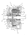
- FIG. 3 is a sectional view of the speed reducer.
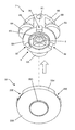
- FIG. 4 is an exploded perspective view of the planetary gear mechanism and the cover member according to the embodiment.
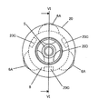
- FIG. 5 is a front view of the planetary gear mechanism and the cover member according to the embodiment.
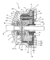
- FIG. 6 is a cross-sectional view of the speed reducer according to the embodiment.
- FIG. 7 is a skeleton diagram of the speed reducer according to the embodiment.
- FIG. 8 is a skeleton diagram of the speed reducer according to the modification.
- FIG. 1 is a perspective view of a planetary gear mechanism 2 used in the reduction gear 1.
- FIG. 2 is a front view of the planetary gear mechanism 2 as seen from the axial direction. 1 and 2, the vertical direction is reversed.
- the axial direction means the direction along the rotation axis of the planetary gear mechanism 2
- the radial direction means the direction orthogonal to the axial direction.
- the planetary gear mechanism 2 includes a sun gear 5 to which a driving force is input, a ring gear 10 to be described later, a plurality of stepped pinions 6 in which a large diameter pinion 6A that meshes with the sun gear 5 and a small diameter pinion 6B that meshes with the ring gear 10 are integrated. , A carrier 8 supporting a plurality of stepped pinions 6. In this specification, the case where the number of stepped pinions 6 is three will be described.
- the carrier 8 includes a first support portion 8A that supports the three stepped pinions 6 from the large diameter pinion 6A side in the axial direction, and a first support portion 8A that supports the plurality of stepped pinions 6 from the side opposite to the first support portion 8A. It further includes two support portions 8B and a pillar portion 8C that passes between the adjacent stepped pinions 6 and connects the first support portion 8A and the second support portion 8B. Each of the first support portion 8A and the second support portion 8B has a circular outer periphery, and both have the same diameter.
- the column portion 8C connects the outer edge of the first support portion 8A and the outer edge of the second support portion 8B, and the radially outer surface of the column portion 8C has an outer circumferential circle of the first support portion 8A and the second support portion 8B. It has an arc with the same curvature as.
- the three stepped pinions 6 are arranged at equal intervals in the circumferential direction of the carrier 8. In addition, in each stepped pinion 6, a part of the outer circumference of the large-diameter pinion 6A projects more radially than the outer circumference of the carrier 8.
- the planetary gear mechanism 2 further includes a differential mechanism 3 described later, and outputs the driving force input from the sun gear 5 via the differential mechanism 3.
- FIG. 3 is a cross-sectional view of the speed reducer 1 including the planetary gear mechanism 2 described above, taken along line III-III in FIG.
- the speed reducer 1 is used to transmit the driving force generated by the driving source to the driving wheels.
- the drive source is an electric motor
- the planetary gear mechanism 2 described above is housed in a casing 4. Further, oil as lubricating oil for lubricating and cooling the planetary gear mechanism 2 and the differential mechanism 3 is injected into the casing 4. As shown, the oil is injected in such an amount that the carrier 8 is partially immersed.
- the large diameter pinion 6A and the small diameter pinion 6B of the stepped pinion 6 are concentrically arranged, and the first shaft 9 penetrates their central axes. Both ends of the first shaft 9 are supported by the first support portion 8A and the second support portion 8B, respectively.
- a ring gear 10 that meshes with the small diameter pinion 6B is arranged on the inner wall of the casing 4.
- the ring gear 10 is an internal gear and is positioned by a snap ring 11 that engages with a groove provided in the inner wall of the casing 4.
- Openings are provided at both ends of the carrier 8 in the axial direction, and projections 8D and 8E projecting outward in the axial direction are provided on the circumference of the openings.
- the planetary gear mechanism 2 is rotatably supported by the casing 4 by press-fitting these protruding portions 8D, 8E into the inner rings of the ball bearings 12, 13 as bearings whose outer rings are fixed to the casing 4.
- the differential mechanism 3 is housed in a space defined by a part of the second support portion 8B and the member 16 of the carrier 8.
- the differential mechanism 3 is similar to a generally known one. That is, the differential mechanism 3 includes a pinion shaft 18 supported by the carrier 8, a pair of pinions 17A, 17B supported by the pinion shaft 18, and a pair of side gears 19A, 19B meshing with the pair of pinions 17A, 17B.
- Prepare The first output shaft 14 is fixed to the side gear 19A
- the second output shaft 15 is fixed to the side gear 19B.
- a drive shaft (not shown) is connected to each of the first output shaft 14 and the second output shaft 15.
- a rotor shaft of an electric motor (not shown) is fixed to the sun gear 5 by press fitting. That is, the output shaft of the reduction gear transmission 1 and the rotor shaft of the electric motor are coaxially aligned.
- the rotor shaft is a hollow tube, and the second output shaft 15 and the drive shaft connected to the second output shaft 15 penetrate through the rotor shaft.
- the driving force input to the sun gear 5 is output via the stepped pinion 6 and the differential mechanism 3. Further, when a difference occurs in the rotational speeds of the two drive wheels, the differential mechanism 3 absorbs the difference.
- FIG. 4 is an exploded perspective view of the planetary gear mechanism 2 and the cover member 20 according to this embodiment.
- FIG. 5 is a front view of the planetary gear mechanism 2 equipped with the cover member 20 as viewed in the axial direction. The vertical direction is reversed in FIGS. 4 and 5.
- FIG. 6 is a sectional view taken along line VI-VI of FIG. 4 to 6, the same parts as those in FIGS. 1 to 3 are given the same part numbers.
- the planetary gear mechanism 2 according to the present embodiment is basically the same as the planetary gear mechanism 2 shown in FIG. 1 and the like, but three concave portions 8E are provided on the back surface of the first support portion 8A. The difference is that it is equipped with.
- the three recesses 8E are provided on the extension lines of the column portions 8C on the back surface of the first support portion 8A, respectively.
- the back surface of the first support portion 8A refers to the surface opposite to the surface supporting the stepped pinion 6.
- the cover member 20 includes a bottom surface 20A facing the back surface of the first support portion 8A, and a wall surface 20B extending from the outer edge of the bottom surface 20A in the same axial direction.
- the bottom surface 20A is provided with three convex portions 20C that engage with the three concave portions 8E. Further, the central portion of the bottom surface 20A is opened so that the protruding portion 8D of the carrier 8 can pass through, and the peripheral edge of this opening portion has an annular contact portion 20D that protrudes in the axial direction similarly to the protruding portion 8D. Are formed.
- the radius of the bottom surface 20A is smaller than the radius of the arcuate trajectory drawn by the large diameter pinion 6A when the planetary gear mechanism 2 rotates. Therefore, the wall surface 20B is provided with a notch 20E for avoiding interference with the large diameter pinion 6A. It is desirable that the clearance between the notch 20E and the large diameter pinion 6A be as small as possible. This is because as the clearance increases, the amount of oil that enters the gap between the notch 20E and the large diameter pinion 6A increases, and the stirring resistance increases.
- the cover member 20 is made of a material lighter than the material forming the carrier 8, such as an aluminum alloy or resin.
- the cover member 20 having the above-described structure is attached to the planetary gear mechanism 2 from the back side of the first support portion 8A.
- the convex portion 20C is pressed into the concave portion 8E.
- the bottom surface 20A of the cover member 20 and the back surface of the first support portion 8A are in contact with each other in a state where the convex portion 20C is pressed into the concave portion 8E.
- the axial end surface of the contact portion 20D of the cover member 20 is a ball bearing that supports the protruding portion 8D on the first support portion 8A side. It contacts the side surface of the inner ring of 12. That is, the cover member 20 is sandwiched between the back surface of the first support portion 8A and the inner ring of the ball bearing 12 and positioned in the axial direction.
- the gear gap which is a space formed between the three large diameter pinions 6A, is covered by the wall surface 20B from the radial direction. As a result, it is possible to suppress the oil surface hitting and the oil scraping by the large diameter pinion 6A.
- the radius of the bottom surface 20A of the cover member 20 is smaller than the radius of the arc-shaped trajectory drawn by the large diameter pinion 6A when the planetary gear mechanism 2 rotates. Therefore, as shown in FIG. 5, when the cover member 20 is mounted on the planetary gear mechanism 2, a part of the large-diameter pinion 6 ⁇ /b>A projects outward in the radial direction from the cover member 20. Strictly speaking, if there is a protruding portion, oil surface striking and oil scraping will occur. However, in the present embodiment, as shown in FIG.
- the radius of the bottom surface 20A of the cover member 20 is close to the radius of the arcuate locus drawn by the large diameter pinion 6A when the planetary gear mechanism 2 rotates. Therefore, the amount of protrusion from the wall surface 20B of the large diameter pinion 6A when the cover member 20 is attached is significantly larger than the amount of protrusion from the outer peripheral surface of the column portion 8C of the large diameter pinion 6A when the cover member 20 is not attached. Becomes smaller. Further, as the radius of the bottom surface 20A of the cover member 20 becomes closer to the radius of the arcuate locus drawn by the large diameter pinion 6A when the planetary gear mechanism 2 rotates, the outer circumference of the large diameter pinion 6A protruding from the notch 20E becomes larger. The curvature of the shape formed by the outer periphery of the wall surface 20B approaches a constant value. As a result, the increase in stirring resistance due to the oil surface striking and oil scraping can be kept within an allowable range.
- the radius of the bottom surface 20A is set so that the increase in stirring resistance falls within the allowable range based on the results of simulations or experiments conducted on a plurality of cover members 20 having different radii.
- the radius of the bottom surface 20A of the cover member 20 is made larger than the radius of the arc-shaped locus drawn by the large diameter pinion 6A when the planetary gear mechanism 2 rotates, so that the entire gear gap and the large diameter pinion 6A. You may make it the structure covered from a direction outer side. In this case, it is not necessary to provide the notch 20E on the wall surface 20B. If the entire structure is covered as described above, the curvature of the outer periphery of the cover member 20 becomes constant, so that it is possible to further suppress the oil surface striking and the oil scraping. However, if it is configured so as to cover the whole, as described below, the size of the casing 4 is increased.
- the clearance between the outer peripheral surface of the large-diameter pinion 6A and the inner wall surface of the casing 4 is set based on the dimensional tolerance of the large-diameter pinion 6A and the dimensional tolerance of the casing 4 without the cover member 20. It will be.
- the clearance between the inner peripheral surface of the wall surface 20B and the outer peripheral surface of the large diameter pinion 6A is set to the dimensional tolerance of the wall surface 20B and the dimensional tolerance of the large diameter pinion 6A. Set based on.
- the clearance between the outer peripheral surface of the wall surface 20B and the inner wall surface of the casing 4 is set based on the dimensional tolerance of the wall surface 20B and the dimensional tolerance of the casing 4. As described above, in the case of the above-described configuration, since the dimensional tolerance to be considered increases, it is unavoidable to increase the radial dimension of the casing 4.
- a part of the large diameter pinion 6A is provided in order to suppress the increase in stirring resistance due to the oil surface striking and the oil scraping without increasing the size of the casing 4, as shown in FIGS. 4 to 6, a part of the large diameter pinion 6A is provided.
- a configuration of projecting from the cover member 20 is adopted. With such a configuration, the amount of lubricating oil supplied to the meshing portion between the sun gear 5 and the plurality of large-diameter pinions 6A is increased, and the lubricating performance is also improved. That is, since the large diameter pinion 6A fixed to the carrier 8 revolves around its own axis, the portion of the large diameter pinion 6A protruding from the cover member 20 scrapes up the oil when entering the oil sump. Then, the scraped oil flows into the inside of the cover member 20 through the gap between the large diameter pinion 6A and the notch 20E, and reaches the meshing portion between the sun gear 5 and the large diameter pinion 6A.
- the gear gap is covered not only from the radial direction but also from the rear surface side in the axial direction by the bottom surface 20A.
- the bottom surface 20A of the cover member 20 is interposed between the back surface of the first support portion 8A and the inner wall surface of the casing 4 facing the back surface. That is, the clearance D between the bottom surface 20A of the cover member 20 and the inner wall surface of the casing 4 is smaller than the clearance between the back surface of the first support portion 8A and the inner wall surface of the casing 4 when the cover member 20 is not mounted. ..
- the clearance between the axial end surface of the planetary gear mechanism 2 and the inner wall surface of the casing 4 can be reduced.
- the amount of oil that flows into the clearance is reduced, so that the oil shear resistance of the axial end surface of the planetary gear mechanism 2 is reduced.
- a plurality of stepped pinions 6 in which a sun gear 5, a ring gear 10, a large diameter pinion 6A that meshes with the sun gear 5 and a small diameter pinion 6B that meshes with the ring gear 10 are integrated, and a plurality of stepped pinions 6 are supported.
- the present invention is applied to a reduction gear transmission 1 including a planetary gear mechanism 2 including a carrier 8 that operates and a casing 4 that accommodates the planetary gear mechanism 2 and oil.
- the reduction gear transmission 1 of the present embodiment includes a cover member 20 that covers a gear gap, which is a plurality of spaces formed between a plurality of large-diameter pinions 6A arranged on the same circle, at least from the radial direction of the large-diameter pinion 6A. ..
- a cover member 20 that is separate from the carrier 8, it is possible to suppress the oil surface hitting and the oil scraping without increasing the size of the carrier 8. That is, the stirring resistance can be reduced while suppressing an increase in the weight of the planetary gear mechanism 2.
- the carrier 8 includes the first support portion 8A that supports the plurality of stepped pinions 6 from the large diameter pinion 6A side, and the first support portion 8A is the side opposite to the surface that supports the plurality of stepped pinions 6.
- the cover member 20 has a convex portion 20C that engages with the concave portion 8E. As a result, it becomes possible to position the cover member 20 in the circumferential direction with a simple structure.
- the carrier 8 is fixed to the other of the inner ring and the outer ring of the ball bearing (bearing) 12 in which one of the inner ring and the outer ring is fixed to the casing 4, and the cover member 20 is the rear surface of the first support portion 8A. And the other side surface of the inner ring or the outer ring.
- the clearance D between the bottom surface 20A of the cover member 20 and the inner wall surface of the casing 4 is larger than the clearance between the back surface of the first support portion 8A and the inner wall surface of the casing 4 when the cover member 20 is not mounted. Get smaller. That is, the oil shear resistance of the bottom surface 20A of the cover member 20 can be reduced.
- the carrier 8 is fixed to the inner ring of the ball bearing 12 whose outer ring is fixed to the casing 4 in the present embodiment
- the inner ring of the ball bearing 12 is fixed to the casing 4 and the carrier 8 is the ball bearing. It may be fixed to 12 outer rings.
- the cover member 20 is sandwiched between the back surface of the first support portion 8A and the side surface of the outer ring of the ball bearing 12.
- the cover member 20 includes a bottom surface 20A facing the back surface of the first support portion 8A, and a wall surface 20B extending from the outer edge of the bottom surface 20A in the same axial direction as the carrier 8.
- the cover member 20 can be mounted from the back side of the planetary gear mechanism 2. That is, since the cover member 20 can be mounted after the assembly of the conventionally known planetary gear mechanism 2 is completed, the assembly process of the reduction gear transmission 1 is not complicated.
- the carrier 8 passes between the second support portion 8B that supports the plurality of stepped pinions 6 from the side opposite to the first support portion 8A and the adjacent stepped pinion 6 and the first support portion 8A.
- a column portion 8C connecting the second support portion 8B to each other, and the recess 8E is provided on an extension line of the column portion 8C. This makes it possible to secure the strength of the carrier 8 while securing the radial dimension and the axial dimension of the recess 8E.
- the convex portion 20C is pressed into the concave portion 8E.
- rattling of the cover member 20 with respect to the carrier 8 in the circumferential direction is suppressed, so that the circumferential clearance between the cover member 20 and the large-diameter pinion 6A in the notch 20E is smaller than that in the case of rattling. can do. If the clearance is reduced, the amount of oil flowing from the clearance to the inside of the cover member 20 is reduced, and thus the stirring resistance is reduced.
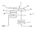
- FIG. 7 is a skeleton diagram of the planetary gear mechanism 2 of the above-described embodiment.
- the differential mechanism 3 is omitted.
- the driving force input from the sun gear 5 is output via the large diameter pinion 6A and the small diameter pinion 6B.
- the cover member 20 is attached to the portion of the large-diameter pinion 6A that projects radially outward from the small-diameter pinion 6B.
- FIG. 8 is a skeleton diagram of the planetary gear mechanism 2-1 according to this modification.
- the planetary gear mechanism 2-1 includes a stepped pinion 102 in which a first sun gear 101, a large diameter pinion 102A that meshes with the first sun gear 101, and a first small diameter pinion 102B that meshes with the ring gear 105 are integrated, and a first small diameter pinion 102B. And a second small diameter pinion 103 that meshes with the second sun gear 104.
- the planetary gear mechanism 2-1 includes a first clutch 107 capable of selectively inhibiting rotation of the ring gear 105 and a second clutch 106 capable of selectively inhibiting rotation of the second sun gear 104.
- the stirring resistance can be reduced by mounting the cover member 20 on the large-diameter pinion 102A as in the above-described embodiment.
- the large-diameter pinion of the stepped pinion is a planetary gear mechanism that rotates without meshing with the ring gear, by mounting the cover member 20 as in the above-described embodiment, the present embodiment The same effect as the form can be obtained.
Landscapes
- Engineering & Computer Science (AREA)
- General Engineering & Computer Science (AREA)
- Mechanical Engineering (AREA)
- General Details Of Gearings (AREA)
- Retarders (AREA)
Abstract
減速装置1は、サンギヤ5と、リングギヤ10と、サンギヤ5と嚙み合う大径ピ二オン6A及びリングギヤ10と嚙み合う小径ピニオン6Bが一体となつた複数の段付きピニオン6と、複数の段付きピニオン6を支持するキャリア8と、を備える遊星歯車機構2と、遊星歯車機構2と潤滑油とを収容するケーシング4と、を備える。減速装置1は、さらに、同一円上に並ぶ複数の大径ピ二オン6Aの間に形成される複数の空間であるギヤ隙間を、少なくとも大径ピ二オン6Aの径方向から覆うカバー部材20を備える。
Description
本発明は、駆動源から入力された動力を遊星歯車機構により減速して出力する減速装置に関する。
減速機構としての遊星歯車機構をケーシングに収容し、さらにケーシング内に遊星歯車機構等の潤滑及び冷却のために潤滑油を注入した減速装置が知られている。このような減速装置においては、注入した潤滑油の撹拌抵抗により動力の伝達効率が低下するという問題がある。JP2012−207693Aには、上記の撹拌抵抗を低減するための構成として、複数の遊星ギヤを支持するキャリアが円板状であり、キャリアの遊星ギヤ取り付け面における遊星ギヤに挟まれるギヤ間部分に凸部を備える構成が開示されている。具体的には、キャリアの外径は遊星ギヤが公転した際の軌跡の最外周の直径に近く、凸部の外周面はキャリアの外周面と一致する円弧状であり、凸部の高さは遊星ギヤの軸方向寸法とほぼ同じである。この構成によれば、ギヤ間部分に凸部があることでギヤ間部分の溜まり油量が減少するので、遊星ギヤが溜まり油をかき分けることによる撹拌抵抗を小さくすることができる。
しかしながら、上記文献の構成では、キャリアの外径が遊星ギヤを支持するという機能から必要となる外径に対し大きくなるので、減速装置の重量増加を招くこととなる。
そこで本発明は、重量増加を抑制しつつ撹拌抵抗の低減が可能な減速装置を提供することを目的とする。
本発明のある態様によれば、サンギヤと、リングギヤと、サンギヤと噛み合う大径ピニオン及びリングギヤと噛み合う小径ピニオンが一体となった複数の段付きピニオンと、複数の段付きピニオンを支持するキャリアと、を備える遊星歯車機構と、遊星歯車機構と潤滑油とを収容するケーシングと、を備える減速装置が提供される。この減速装置は、同一円上に並ぶ複数の大径ピニオンの間に形成される複数の空間であるギヤ隙間を、少なくとも大径ピニオンの径方向から覆うカバー部材を備える。
以下、図面を参照して、本発明の実施形態について説明する。
図1は、減速装置1に用いる遊星歯車機構2の斜視図である。図2は遊星歯車機構2を軸方向から見た正面図である。なお、図1と図2では上下方向が逆転している。また、本明細書において、軸方向とは遊星歯車機構2の回転軸に沿う方向のことをいい、径方向とは軸方向と直交する方向のことをいう。
遊星歯車機構2は、駆動力が入力されるサンギヤ5と、後述するリングギヤ10と、サンギヤ5と噛み合う大径ピニオン6A及びリングギヤ10と噛み合う小径ピニオン6Bが一体となった複数の段付きピニオン6と、複数の段付きピニオン6を支持するキャリア8とを備える。なお、本明細書では段付きピニオン6が3個の場合について説明する。
キャリア8は、3個の段付きピニオン6を軸方向の大径ピニオン6A側から支持する第1支持部8Aと、第1支持部8Aとは反対側から複数の段付きピニオン6を支持する第2支持部8Bと、隣り合う段付きピニオン6の間を通り第1支持部8Aと第2支持部8Bとを接続する柱部8Cとをさらに備える。第1支持部8Aと第2支持部8Bは、いずれも外周が円形であり、両者の直径は等しい。柱部8Cは第1支持部8Aの外縁と第2支持部8Bの外縁とをつないでおり、柱部8Cの径方向外側の面は、第1支持部8A及び第2支持部8Bの外周円と同じ曲率の円弧になっている。
3個の段付きピニオン6はキャリア8の周方向に等間隔で配置されている。また、各段付きピニオン6は、大径ピニオン6Aの外周の一部がキャリア8の外周よりも径方向に突出している。
遊星歯車機構2は、後述する差動機構3を更に備え、サンギヤ5から入力された駆動力を、差動機構3を介して出力する。
図3は、上記の遊星歯車機構2を備える減速装置1の、図2のIII−III線に沿った断面図である。この減速装置1は、駆動源が発生した駆動力を駆動輪に伝達するために用いる。本実施形態では、駆動源が電動モータである場合について説明する。
上述した遊星歯車機構2は、ケーシング4に収容されている。また、ケーシング4には、遊星歯車機構2や差動機構3の潤滑及び冷却のための潤滑油としてのオイルが注入されている。オイルは、図示する通り、キャリア8の一部が浸る程度の量が注入される。
段付きピニオン6の大径ピニオン6Aと小径ピニオン6Bは同心状に並び、それらの中心軸を第1シャフト9が貫通する。第1シャフト9の両端部はそれぞれ第1支持部8Aと第2支持部8Bに支持される。
ケーシング4の内壁には、小径ピニオン6Bと噛み合うリングギヤ10が配置されている。リングギヤ10は内歯歯車であり、ケーシング4の内壁に設けられた溝に係合するスナップリング11により位置決めされている。
キャリア8の軸方向の両端部には開口部が設けられており、開口部の周上には軸方向外側に突出する突出部8D、8Eが設けられている。これら突出部8D、8Eが、外輪がケーシング4に固定された軸受としてのボールベアリング12、13の内輪に圧入されることにより、遊星歯車機構2はケーシング4に回転自在に支持される。
キャリア8の、第2支持部8Bの一部と部材16とで画成される空間には、差動機構3が収容されている。差動機構3は、一般的に知られているものと同様である。すなわち、差動機構3は、キャリア8に支持されるピニオンシャフト18と、ピニオンシャフト18に支持される一対のピニオン17A、17Bと、一対のピニオン17A、17Bと噛み合う一対のサイドギヤ19A、19Bとを備える。サイドギヤ19Aには第1出力軸14が、サイドギヤ19Bには第2出力軸15が、それぞれ固定されている。
第1出力軸14及び第2出力軸15には、それぞれ図示しないドライブシャフトが接続される。なお、サンギヤ5には図示しない電動モータのロータシャフトが圧入により固定される。つまり、減速装置1の出力軸と電動モータのロータシャフトとが、同軸上に並ぶこととなる。そして、ロータシャフトは中空管であり、第2出力軸15及びこれに接続されるドライブシャフトは、ロータシャフトの中を貫通する。
上記構成により、サンギヤ5に入力された駆動力は、段付きピニオン6及び差動機構3を介して出力される。また、2つの駆動輪の回転速度に差が生じた場合には、差動機構3によりその差が吸収される。
ところで、上記の減速装置1では、遊星歯車機構2が回転すると、大径ピニオン6Aがオイル溜まりに入る際に、大径ピニオン6Aのキャリア8から径方向外側に突出した部分がオイル面を叩く(以下、これをオイル面叩きともいう)。また、大径ピニオン6Aがオイル溜まりから出る際に、オイルを大径ピニオン6Aのキャリア8から径方向外側に突出した部分がオイルを掻き上げる(以下、これをオイル掻き上げともいう)。このオイル面叩きとオイル掻き上げとが生じると、遊星歯車機構2が回転する際のオイルの撹拌抵抗が増大する。そして、撹拌抵抗が増大するほど、動力伝達効率が低下してしまう。なお、ケーシング4とは別体のオイルパンを設けてオイルを循環させる構成にすれば、上記の撹拌抵抗が増大するという課題は生じない。しかし、当該構成では、別体のオイルパンとオイル循環用のポンプ及び配管とを設置するスペースが必要となる。したがって、電動モータが後輪駆動用の場合のように、電動モータと減速装置1とを限られたスペースに配置しなければならないときには、別体のオイルパンを用いることは難しい。
そこで本実施形態では、以下に説明する構成にすることで、撹拌抵抗の増大を抑制する。
図4は、本実施形態にかかる遊星歯車機構2及びカバー部材20の分解斜視図である。図5は、カバー部材20を装着した遊星歯車機構2を軸方向から見た正面図である。なお、図4と図5では上下方向が逆転している。図6は、図5のVI−VI線に沿った断面図である。図4から図6では、図1から図3と同様の部品には同じ部品番号を付してある。
図4に示すように、本実施形態にかかる遊星歯車機構2は、基本的には図1等に示した遊星歯車機構2と同様であるが、第1支持部8Aの背面に3つの凹部8Eを備える点が相違する。3つの凹部8Eは、それぞれ第1支持部8Aの背面の、柱部8Cの延長線上に設けられている。なお、第1支持部8Aの背面とは、段付きピニオン6を支持する面と反対側の面のことをいう。
凹部8Eを上記の位置に設けることで、凹部8Eを設けることによる第1支持部8Aの強度低下を抑制できる。
カバー部材20は、第1支持部8Aの背面と対向する底面20Aと、底面20Aの外縁から軸方向と同方向に伸びる壁面20Bとを備える。底面20Aには、3つの凹部8Eに係合する3つの凸部20Cが設けられている。また、底面20Aの中央部は、キャリア8の突出部8Dが通るように開口しており、この開口部の周縁には、突出部8Dと同様に軸方向に突出する円環状の当接部20Dが形成されている。
底面20Aの半径は、遊星歯車機構2が回転したときに大径ピニオン6Aが描く円弧状の軌跡の半径よりも小さい。このため、壁面20Bには大径ピニオン6Aとの干渉を避けるための切り欠き20Eが設けられている。切り欠き20Eと大径ピニオン6Aとのクリアランスは、できるだけ小さい方が望ましい。これは、クリアランスが大きくなるほど、切り欠き20Eと大径ピニオン6Aとの隙間に進入するオイル量が増えて、撹拌抵抗が増大するからである。
なお、カバー部材20は、キャリア8を形成する素材よりも軽量な素材、例えばアルミ合金や樹脂等により形成される。
上記のような構成のカバー部材20を、図4に示す通りカバー部材20を第1支持部8Aの背面側から遊星歯車機構2に装着する。このとき、凸部20Cを凹部8Eに圧入する。凸部20Cが凹部8Eに圧入された状態で、カバー部材20の底面20Aと第1支持部8Aの背面は接触している。凸部20Cと凹部8Eとが係合することにより、カバー部材20のキャリア8に対する周方向の動きが規制される。つまり、カバー部材20の周方向の位置決めがなされる。
また、図6に示す通り、遊星歯車機構2をケーシング4に収容した状態で、カバー部材20の当接部20Dの軸方向端面は、第1支持部8A側の突出部8Dを支持するボールベアリング12の内輪の側面に当接する。すなわち、カバー部材20は、第1支持部8Aの背面とボールベアリング12の内輪とで挟持されて、軸方向の位置決めがなされる。
そして、カバー部材20を遊星歯車機構2に装着することで、3つの大径ピニオン6Aの間に形成される空間であるギヤ隙間が、径方向からは壁面20Bにより覆わる。これにより、大径ピニオン6Aによるオイル面叩き及びオイル掻き上げを抑制できる。
ところで、上述した通り、カバー部材20の底面20Aの半径は、遊星歯車機構2が回転したときに大径ピニオン6Aが描く円弧状の軌跡の半径よりも小さい。このため、図5に示す通り、カバー部材20を遊星歯車機構2に装着した状態では、大径ピニオン6Aの一部がカバー部材20よりも半径方向外側に突出する。厳密にいえば、突出する部分があればオイル面叩き及びオイル掻き上げは生じる。しかし、本実施形態では、図5に示す通り、カバー部材20の底面20Aの半径は、遊星歯車機構2が回転したときに大径ピニオン6Aが描く円弧状の軌跡の半径に近い。したがって、カバー部材20を装着した場合における大径ピニオン6Aの壁面20Bからの突出量は、カバー部材20を装着しない場合における大径ピニオン6Aの柱部8Cの外周面からの突出量に比べて大幅に小さくなる。また、カバー部材20の底面20Aの半径が、遊星歯車機構2が回転したときに大径ピニオン6Aが描く円弧状の軌跡の半径に近づくほど、切り欠き20Eから突出する大径ピニオン6Aの外周と壁面20Bの外周とで形成される形状の曲率が一定に近づく。その結果、オイル面叩き及びオイル掻き上げによる撹拌抵抗の増大を許容範囲内に収めることができる。
底面20Aの半径は、半径の異なる複数のカバー部材20についてシミュレーションまたは実験を行ない、その結果に基づいて、撹拌抵抗の増大が許容範囲内に収まるように設定する。
なお、カバー部材20の底面20Aの半径を、遊星歯車機構2が回転したときに大径ピニオン6Aが描く円弧状の軌跡の半径よりも大きくして、ギヤ隙間及び大径ピニオン6Aの全体を径方向外側から覆う構成にしてもよい。この場合、壁面20Bに切り欠き20Eを設ける必要はなくなる。上記のように全体を覆う構成にすれば、カバー部材20の外周の曲率は一定になるので、オイル面叩き及びオイル掻き上げをより抑制することが可能となる。ただし、全体を覆う構成にすると、以下に説明する通り、ケーシング4の大型化を招来することとなる。
ケーシング4を設計するにあたり、大径ピニオン6Aの外周面とケーシング4の内壁面とのクリアランスは、カバー部材20がなければ大径ピニオン6Aの寸法公差とケーシング4の寸法公差とに基づいて設定することになる。これに対し、カバー部材20を装着する場合には、まず、壁面20Bの内周面と大径ピニオン6Aの外周面とのクリアランスを、壁面20Bの寸法公差と大径ピニオン6Aの寸法公差とに基づいて設定する。さらに、壁面20Bの外周面とケーシング4の内壁面とのクリアランスを、壁面20Bの寸法公差とケーシング4の寸法公差とに基づいて設定する。このように、上記構成にする場合には、考慮すべき寸法公差が多くなることにより、ケーシング4の径方向寸法を大きくせざるを得ない。
そこで本実施形態では、ケーシング4を大型化することなく、オイル面叩き及びオイル掻き上げによる撹拌抵抗の増大を抑制するために、図4から図6に示す通り、大径ピニオン6Aの一部がカバー部材20から突出する構成を採用する。なお、このような構成にすると、サンギヤ5と複数の大径ピニオン6Aとの噛み合い部への潤滑油の供給量が増加し、潤滑性能が向上するという効果も得られる。すなわち、キャリア8に固定された大径ピニオン6Aは自転しながら公転するので、大径ピニオン6Aのカバー部材20から突出した部分はオイル溜まりに入るとオイルを掻き上げる。そして、掻きあげられたオイルは大径ピニオン6Aと切り欠き20Eとの隙間からカバー部材20の内側へ流れ込み、サンギヤ5と大径ピニオン6Aとの噛み合い部に到達する。
また、ギヤ隙間は、径方向からだけでなく、底面20Aにより軸方向の背面側からも覆われる。その結果、第1支持部8Aの背面と、当該背面と対向するケーシング4の内壁面との間に、カバー部材20の底面20Aが介在することとなる。すなわち、カバー部材20の底面20Aと上記ケーシング4の内壁面とのクリアランスDは、カバー部材20を装着しない場合の第1支持部8Aの背面と上記ケーシング4の内壁面とのクリアランスに比べて小さい。換言すると、カバー部材20を装着することで、遊星歯車機構2の軸方向端面とケーシング4の内壁面とのクリアランスを小さくすることができる。これにより、カバー部材20を装着しない場合に比べて、当該クリアランスへのオイル流入量が減少するので、遊星歯車機構2の軸方向端面のオイルせん断抵抗が低下する。
次に、本実施形態により得られる作用効果について説明する。
本実施形態は、サンギヤ5と、リングギヤ10と、サンギヤ5と噛み合う大径ピニオン6A及びリングギヤ10と噛み合う小径ピニオン6Bが一体となった複数の段付きピニオン6と、複数の段付きピニオン6を支持するキャリア8とを備える遊星歯車機構2と、遊星歯車機構2とオイルとを収容するケーシング4とを備える減速装置1に適用される。本実施形態の減速装置1は、同一円上に並ぶ複数の大径ピニオン6Aの間に形成される複数の空間であるギヤ隙間を、少なくとも大径ピニオン6Aの径方向から覆うカバー部材20を備える。このように、キャリア8とは別体のカバー部材20を用いることにより、キャリア8を大型化することなくオイル面叩き及びオイル掻き上げ等を抑制できる。すなわち、遊星歯車機構2の重量増加を抑制しつつ撹拌抵抗を低減できる。
本実施形態では、キャリア8は複数の段付きピニオン6を大径ピニオン6A側から支持する第1支持部8Aを備え、第1支持部8Aは複数の段付きピニオン6を支持する面と反対側の面である背面に、少なくとも1つの凹部8Eを有し、カバー部材20は、凹部8Eに係合する凸部20Cを備える。これにより、簡易な構造でカバー部材20の周方向の位置決めをすることが可能となる。
本実施形態では、キャリア8は、内輪または外輪の一方がケーシング4に固定されるボールベアリング(軸受)12の、内輪または外輪の他方に固定され、カバー部材20は、第1支持部8Aの背面と内輪または外輪の他方の側面とに挟持される。これにより、カバー部材20の底面20Aと上記ケーシング4の内壁面とのクリアランスDは、カバー部材20を装着しない場合の第1支持部8Aの背面と上記ケーシング4の内壁面とのクリアランスに比べて小さくなる。すなわち、カバー部材20の底面20Aのオイルせん断抵抗を低減できる。なお、本実施形態では、外輪がケーシング4に固定されるボールベアリング12の内輪にキャリア8が固定される構成について説明したが、ボールベアリング12の内輪がケーシング4に固定され、キャリア8がボールベアリング12の外輪に固定される構成であってもよい。この場合、カバー部材20は、第1支持部8Aの背面とボールベアリング12の外輪の側面とに挟持される。
本実施形態では、カバー部材20が、第1支持部8Aの背面と対向する底面20Aと、底面20Aの外縁からキャリア8の軸方向と同方向に伸びる壁面20Bとを備える。このような構成にすることで、遊星歯車機構2の上記背面側からカバー部材20を装着することができる。すなわち、従来から知られている遊星歯車機構2の組み立てが終了した後にカバー部材20を装着することができるので、減速装置1の組み立て工程が複雑化することはない。
本実施形態では、キャリア8は、第1支持部8Aとは反対側から複数の段付きピニオン6を支持する第2支持部8Bと、隣り合う段付きピニオン6の間を通り第1支持部8Aと第2支持部8Bとを接続する柱部8Cとを備え、凹部8Eは柱部8Cの延長線上に設けられている。これにより、凹部8Eの径方向寸法及び軸方向寸法を確保しつつ、キャリア8の強度も確保できる。
本実施形態では、凸部20Cは凹部8Eに圧入されている。これにより、カバー部材20のキャリア8に対する周方向のガタつきが抑制されるので、切り欠き20Eにおけるカバー部材20と大径ピニオン6Aとの周方向のクリアランスを、ガタつきがある場合に比べて小さくすることができる。そして、当該クリアランスを小さくすれば、当該クリアランスからカバー部材20の内側へのオイル流入量が少なくなるので、撹拌抵抗が低下する。
次に、上述した実施形態の変形例について説明する。本変形例も、本願発明の範囲に含まれる。
図7は、上述した実施形態の遊星歯車機構2のスケルトン図である。なお、図7では、差動機構3を省略している。図示する通り、サンギヤ5から入力された駆動力は、大径ピニオン6A及び小径ピニオン6Bを介して出力される。そして、小径ピニオン6Bよりも径方向外側に突出する大径ピニオン6Aの部分にカバー部材20が装着される。
これに対し、図8は本変形例にかかる遊星歯車機構2−1のスケルトン図である。遊星歯車機構2−1は、第1サンギヤ101と、第1サンギヤ101と噛み合う大径ピニオン102A及びリングギヤ105と噛み合う第1小径ピニオン102Bが一体となった段付きピニオン102と、第1小径ピニオン102B及び第2サンギヤ104と噛み合う第2小径ピニオン103とを備える。また、遊星歯車機構2−1は、リングギヤ105の回転を選択的に禁止できる第1クラッチ107と、第2サンギヤ104の回転を選択的に禁止できる第2クラッチ106とを備える。
上述した構成の遊星歯車機構2−1についても、大径ピニオン102Aの部分に上述した実施形態と同様にカバー部材20を装着することで、撹拌抵抗を低減することができる。遊星歯車機構2−1の他にも、段付きピニオンの大径ピニオンがリングギヤと噛み合うことなく回転する遊星歯車機構であれば、上述した実施形態と同様にカバー部材20を装着することで本実施形態と同様の作用効果が得られる。
以上、本発明の実施形態について説明したが、上記実施形態は本発明の適用例の一部を示したに過ぎず、本発明の技術的範囲を上記実施形態の具体的構成に限定する趣旨ではない。
Claims (6)
- サンギヤと、リングギヤと、前記サンギヤと噛み合う大径ピニオン及び前記リングギヤと噛み合う小径ピニオンが一体となった複数の段付きピニオンと、複数の前記段付きピニオンを支持するキャリアと、
を備える遊星歯車機構と、
前記遊星歯車機構と潤滑油とを収容するケーシングと、
を備える減速装置において、
同一円上に並ぶ複数の前記大径ピニオンの間に形成される複数の空間であるギヤ隙間を、少なくとも前記大径ピニオンの径方向から覆うカバー部材を備える減速装置。 - 請求項1に記載の減速装置において、
前記キャリアは、複数の前記段付きピニオンを前記大径ピニオン側から支持する第1支持部を備え、
前記第1支持部は、複数の前記段付きピニオンを支持する面と反対側の面である背面に、少なくとも1つの凹部を有し、
前記カバー部材は、前記凹部に係合する凸部を備える、減速装置。 - 請求項2に記載の減速装置において、
前記キャリアは、内輪または外輪の一方が前記ケーシングに固定される軸受の、前記内輪または前記外輪の他方に固定され、
前記カバー部材は、前記背面と前記内輪または前記外輪の他方の側面とに挟持される、減速装置。 - 請求項2または3に記載の減速装置において、
前記カバー部材は、前記背面と対向する底面と、前記底面の外縁から前記キャリアの軸方向と同方向に伸びる壁面と、をさらに備える減速装置。 - 請求項2から4のいずれか一項に記載の減速装置において、
前記キャリアは、前記第1支持部とは反対側から複数の前記段付きピニオンを支持する第2支持部と、隣り合う前記段付きピニオンの間を通り前記第1支持部と前記第2支持部とを接続する柱部と、をさらに備え、
前記凹部は前記柱部の延長線上に設けられている、減速装置。 - 請求項2から5のいずれか一項に記載の減速装置において、
前記凸部は前記凹部に圧入されている減速装置。
Priority Applications (2)
| Application Number | Priority Date | Filing Date | Title |
|---|---|---|---|
| JP2020571909A JP7099555B2 (ja) | 2019-02-15 | 2019-02-15 | 減速装置 |
| PCT/IB2019/000173 WO2020165620A1 (ja) | 2019-02-15 | 2019-02-15 | 減速装置 |
Applications Claiming Priority (1)
| Application Number | Priority Date | Filing Date | Title |
|---|---|---|---|
| PCT/IB2019/000173 WO2020165620A1 (ja) | 2019-02-15 | 2019-02-15 | 減速装置 |
Publications (1)
| Publication Number | Publication Date |
|---|---|
| WO2020165620A1 true WO2020165620A1 (ja) | 2020-08-20 |
Family
ID=72044699
Family Applications (1)
| Application Number | Title | Priority Date | Filing Date |
|---|---|---|---|
| PCT/IB2019/000173 Ceased WO2020165620A1 (ja) | 2019-02-15 | 2019-02-15 | 減速装置 |
Country Status (2)
| Country | Link |
|---|---|
| JP (1) | JP7099555B2 (ja) |
| WO (1) | WO2020165620A1 (ja) |
Citations (2)
| Publication number | Priority date | Publication date | Assignee | Title |
|---|---|---|---|---|
| JP2012207693A (ja) * | 2011-03-29 | 2012-10-25 | Kobelco Contstruction Machinery Ltd | 建設機械の駆動装置 |
| JP2015068492A (ja) * | 2013-10-01 | 2015-04-13 | 川崎重工業株式会社 | 潤滑油整流構造を備えた遊星歯車装置 |
-
2019
- 2019-02-15 JP JP2020571909A patent/JP7099555B2/ja active Active
- 2019-02-15 WO PCT/IB2019/000173 patent/WO2020165620A1/ja not_active Ceased
Patent Citations (2)
| Publication number | Priority date | Publication date | Assignee | Title |
|---|---|---|---|---|
| JP2012207693A (ja) * | 2011-03-29 | 2012-10-25 | Kobelco Contstruction Machinery Ltd | 建設機械の駆動装置 |
| JP2015068492A (ja) * | 2013-10-01 | 2015-04-13 | 川崎重工業株式会社 | 潤滑油整流構造を備えた遊星歯車装置 |
Also Published As
| Publication number | Publication date |
|---|---|
| JP7099555B2 (ja) | 2022-07-12 |
| JPWO2020165620A1 (ja) | 2021-12-02 |
Similar Documents
| Publication | Publication Date | Title |
|---|---|---|
| JP5792015B2 (ja) | インホイールモータ駆動装置 | |
| CN104626961B (zh) | 混合动力车辆驱动装置 | |
| US20090017954A1 (en) | Lubricating oil feeding device for automatic transmission | |
| JPWO2013129144A1 (ja) | 車両用駆動装置 | |
| CN114375375B (zh) | 传动装置 | |
| JP7392218B2 (ja) | 潤滑構造 | |
| CN114450506B (zh) | 传动装置 | |
| US20150233466A1 (en) | Automatic transmission | |
| CN114901970B (zh) | 动力传递装置 | |
| JPH08270767A (ja) | 遊星歯車機構の潤滑油供給構造 | |
| JP2016191418A (ja) | 差動装置 | |
| JP3393697B2 (ja) | 遊星歯車装置におけるピニオンシャフトの潤滑構造 | |
| JP2017101712A (ja) | 伝動装置及び差動装置 | |
| JP2016080152A (ja) | 差動装置 | |
| JP2003247629A (ja) | 遊星歯車機構 | |
| US11009079B2 (en) | Vehicle drive apparatus | |
| EP2778469B1 (en) | Wheel driving apparatus | |
| US10167938B2 (en) | Compact planetary differential | |
| JP7099555B2 (ja) | 減速装置 | |
| JP2010065741A (ja) | 車両用自動変速機の潤滑構造 | |
| JP2019183871A (ja) | 差動装置 | |
| JP7317128B2 (ja) | 伝動装置 | |
| KR20230082070A (ko) | 이너파이프를 이용한 유성기어세트의 윤활구조 | |
| JP2017180812A (ja) | 遊星歯車装置 | |
| JP7861751B2 (ja) | 歯車装置の潤滑構造 |
Legal Events
| Date | Code | Title | Description |
|---|---|---|---|
| 121 | Ep: the epo has been informed by wipo that ep was designated in this application |
Ref document number: 19914700 Country of ref document: EP Kind code of ref document: A1 |
|
| ENP | Entry into the national phase |
Ref document number: 2020571909 Country of ref document: JP Kind code of ref document: A |
|
| NENP | Non-entry into the national phase |
Ref country code: DE |
|
| 122 | Ep: pct application non-entry in european phase |
Ref document number: 19914700 Country of ref document: EP Kind code of ref document: A1 |