WO2020162616A1 - ボルト、及びボルト用鋼材 - Google Patents
ボルト、及びボルト用鋼材 Download PDFInfo
- Publication number
- WO2020162616A1 WO2020162616A1 PCT/JP2020/004916 JP2020004916W WO2020162616A1 WO 2020162616 A1 WO2020162616 A1 WO 2020162616A1 JP 2020004916 W JP2020004916 W JP 2020004916W WO 2020162616 A1 WO2020162616 A1 WO 2020162616A1
- Authority
- WO
- WIPO (PCT)
- Prior art keywords
- less
- bolt
- hydrogen
- amount
- delayed fracture
- Prior art date
- Legal status (The legal status is an assumption and is not a legal conclusion. Google has not performed a legal analysis and makes no representation as to the accuracy of the status listed.)
- Ceased
Links
Classifications
-
- C—CHEMISTRY; METALLURGY
- C22—METALLURGY; FERROUS OR NON-FERROUS ALLOYS; TREATMENT OF ALLOYS OR NON-FERROUS METALS
- C22C—ALLOYS
- C22C38/00—Ferrous alloys, e.g. steel alloys
- C22C38/18—Ferrous alloys, e.g. steel alloys containing chromium
- C22C38/40—Ferrous alloys, e.g. steel alloys containing chromium with nickel
- C22C38/44—Ferrous alloys, e.g. steel alloys containing chromium with nickel with molybdenum or tungsten
-
- C—CHEMISTRY; METALLURGY
- C22—METALLURGY; FERROUS OR NON-FERROUS ALLOYS; TREATMENT OF ALLOYS OR NON-FERROUS METALS
- C22C—ALLOYS
- C22C38/00—Ferrous alloys, e.g. steel alloys
- C22C38/18—Ferrous alloys, e.g. steel alloys containing chromium
- C22C38/40—Ferrous alloys, e.g. steel alloys containing chromium with nickel
- C22C38/46—Ferrous alloys, e.g. steel alloys containing chromium with nickel with vanadium
-
- C—CHEMISTRY; METALLURGY
- C21—METALLURGY OF IRON
- C21D—MODIFYING THE PHYSICAL STRUCTURE OF FERROUS METALS; GENERAL DEVICES FOR HEAT TREATMENT OF FERROUS OR NON-FERROUS METALS OR ALLOYS; MAKING METAL MALLEABLE, e.g. BY DECARBURISATION OR TEMPERING
- C21D6/00—Heat treatment of ferrous alloys
- C21D6/004—Heat treatment of ferrous alloys containing Cr and Ni
-
- C—CHEMISTRY; METALLURGY
- C21—METALLURGY OF IRON
- C21D—MODIFYING THE PHYSICAL STRUCTURE OF FERROUS METALS; GENERAL DEVICES FOR HEAT TREATMENT OF FERROUS OR NON-FERROUS METALS OR ALLOYS; MAKING METAL MALLEABLE, e.g. BY DECARBURISATION OR TEMPERING
- C21D6/00—Heat treatment of ferrous alloys
- C21D6/005—Heat treatment of ferrous alloys containing Mn
-
- C—CHEMISTRY; METALLURGY
- C21—METALLURGY OF IRON
- C21D—MODIFYING THE PHYSICAL STRUCTURE OF FERROUS METALS; GENERAL DEVICES FOR HEAT TREATMENT OF FERROUS OR NON-FERROUS METALS OR ALLOYS; MAKING METAL MALLEABLE, e.g. BY DECARBURISATION OR TEMPERING
- C21D6/00—Heat treatment of ferrous alloys
- C21D6/008—Heat treatment of ferrous alloys containing Si
-
- C—CHEMISTRY; METALLURGY
- C21—METALLURGY OF IRON
- C21D—MODIFYING THE PHYSICAL STRUCTURE OF FERROUS METALS; GENERAL DEVICES FOR HEAT TREATMENT OF FERROUS OR NON-FERROUS METALS OR ALLOYS; MAKING METAL MALLEABLE, e.g. BY DECARBURISATION OR TEMPERING
- C21D9/00—Heat treatment, e.g. annealing, hardening, quenching or tempering, adapted for particular articles; Furnaces therefor
- C21D9/0093—Heat treatment, e.g. annealing, hardening, quenching or tempering, adapted for particular articles; Furnaces therefor for screws; for bolts
-
- C—CHEMISTRY; METALLURGY
- C22—METALLURGY; FERROUS OR NON-FERROUS ALLOYS; TREATMENT OF ALLOYS OR NON-FERROUS METALS
- C22C—ALLOYS
- C22C32/00—Non-ferrous alloys containing at least 5% by weight but less than 50% by weight of oxides, carbides, borides, nitrides, silicides or other metal compounds, e.g. oxynitrides, sulfides, whether added as such or formed in situ
- C22C32/0047—Non-ferrous alloys containing at least 5% by weight but less than 50% by weight of oxides, carbides, borides, nitrides, silicides or other metal compounds, e.g. oxynitrides, sulfides, whether added as such or formed in situ with carbides, nitrides, borides or silicides as the main non-metallic constituents
- C22C32/0052—Non-ferrous alloys containing at least 5% by weight but less than 50% by weight of oxides, carbides, borides, nitrides, silicides or other metal compounds, e.g. oxynitrides, sulfides, whether added as such or formed in situ with carbides, nitrides, borides or silicides as the main non-metallic constituents only carbides
-
- C—CHEMISTRY; METALLURGY
- C22—METALLURGY; FERROUS OR NON-FERROUS ALLOYS; TREATMENT OF ALLOYS OR NON-FERROUS METALS
- C22C—ALLOYS
- C22C38/00—Ferrous alloys, e.g. steel alloys
-
- C—CHEMISTRY; METALLURGY
- C22—METALLURGY; FERROUS OR NON-FERROUS ALLOYS; TREATMENT OF ALLOYS OR NON-FERROUS METALS
- C22C—ALLOYS
- C22C38/00—Ferrous alloys, e.g. steel alloys
- C22C38/001—Ferrous alloys, e.g. steel alloys containing N
-
- C—CHEMISTRY; METALLURGY
- C22—METALLURGY; FERROUS OR NON-FERROUS ALLOYS; TREATMENT OF ALLOYS OR NON-FERROUS METALS
- C22C—ALLOYS
- C22C38/00—Ferrous alloys, e.g. steel alloys
- C22C38/002—Ferrous alloys, e.g. steel alloys containing In, Mg, or other elements not provided for in one single group C22C38/001 - C22C38/60
-
- C—CHEMISTRY; METALLURGY
- C22—METALLURGY; FERROUS OR NON-FERROUS ALLOYS; TREATMENT OF ALLOYS OR NON-FERROUS METALS
- C22C—ALLOYS
- C22C38/00—Ferrous alloys, e.g. steel alloys
- C22C38/005—Ferrous alloys, e.g. steel alloys containing rare earths, i.e. Sc, Y, Lanthanides
-
- C—CHEMISTRY; METALLURGY
- C22—METALLURGY; FERROUS OR NON-FERROUS ALLOYS; TREATMENT OF ALLOYS OR NON-FERROUS METALS
- C22C—ALLOYS
- C22C38/00—Ferrous alloys, e.g. steel alloys
- C22C38/02—Ferrous alloys, e.g. steel alloys containing silicon
-
- C—CHEMISTRY; METALLURGY
- C22—METALLURGY; FERROUS OR NON-FERROUS ALLOYS; TREATMENT OF ALLOYS OR NON-FERROUS METALS
- C22C—ALLOYS
- C22C38/00—Ferrous alloys, e.g. steel alloys
- C22C38/04—Ferrous alloys, e.g. steel alloys containing manganese
-
- C—CHEMISTRY; METALLURGY
- C22—METALLURGY; FERROUS OR NON-FERROUS ALLOYS; TREATMENT OF ALLOYS OR NON-FERROUS METALS
- C22C—ALLOYS
- C22C38/00—Ferrous alloys, e.g. steel alloys
- C22C38/06—Ferrous alloys, e.g. steel alloys containing aluminium
-
- C—CHEMISTRY; METALLURGY
- C22—METALLURGY; FERROUS OR NON-FERROUS ALLOYS; TREATMENT OF ALLOYS OR NON-FERROUS METALS
- C22C—ALLOYS
- C22C38/00—Ferrous alloys, e.g. steel alloys
- C22C38/18—Ferrous alloys, e.g. steel alloys containing chromium
- C22C38/26—Ferrous alloys, e.g. steel alloys containing chromium with niobium or tantalum
-
- C—CHEMISTRY; METALLURGY
- C22—METALLURGY; FERROUS OR NON-FERROUS ALLOYS; TREATMENT OF ALLOYS OR NON-FERROUS METALS
- C22C—ALLOYS
- C22C38/00—Ferrous alloys, e.g. steel alloys
- C22C38/18—Ferrous alloys, e.g. steel alloys containing chromium
- C22C38/28—Ferrous alloys, e.g. steel alloys containing chromium with titanium or zirconium
-
- C—CHEMISTRY; METALLURGY
- C22—METALLURGY; FERROUS OR NON-FERROUS ALLOYS; TREATMENT OF ALLOYS OR NON-FERROUS METALS
- C22C—ALLOYS
- C22C38/00—Ferrous alloys, e.g. steel alloys
- C22C38/18—Ferrous alloys, e.g. steel alloys containing chromium
- C22C38/32—Ferrous alloys, e.g. steel alloys containing chromium with boron
-
- C—CHEMISTRY; METALLURGY
- C22—METALLURGY; FERROUS OR NON-FERROUS ALLOYS; TREATMENT OF ALLOYS OR NON-FERROUS METALS
- C22C—ALLOYS
- C22C38/00—Ferrous alloys, e.g. steel alloys
- C22C38/18—Ferrous alloys, e.g. steel alloys containing chromium
- C22C38/40—Ferrous alloys, e.g. steel alloys containing chromium with nickel
- C22C38/42—Ferrous alloys, e.g. steel alloys containing chromium with nickel with copper
-
- C—CHEMISTRY; METALLURGY
- C22—METALLURGY; FERROUS OR NON-FERROUS ALLOYS; TREATMENT OF ALLOYS OR NON-FERROUS METALS
- C22C—ALLOYS
- C22C38/00—Ferrous alloys, e.g. steel alloys
- C22C38/18—Ferrous alloys, e.g. steel alloys containing chromium
- C22C38/40—Ferrous alloys, e.g. steel alloys containing chromium with nickel
- C22C38/50—Ferrous alloys, e.g. steel alloys containing chromium with nickel with titanium or zirconium
-
- C—CHEMISTRY; METALLURGY
- C22—METALLURGY; FERROUS OR NON-FERROUS ALLOYS; TREATMENT OF ALLOYS OR NON-FERROUS METALS
- C22C—ALLOYS
- C22C38/00—Ferrous alloys, e.g. steel alloys
- C22C38/18—Ferrous alloys, e.g. steel alloys containing chromium
- C22C38/40—Ferrous alloys, e.g. steel alloys containing chromium with nickel
- C22C38/54—Ferrous alloys, e.g. steel alloys containing chromium with nickel with boron
-
- F—MECHANICAL ENGINEERING; LIGHTING; HEATING; WEAPONS; BLASTING
- F16—ENGINEERING ELEMENTS AND UNITS; GENERAL MEASURES FOR PRODUCING AND MAINTAINING EFFECTIVE FUNCTIONING OF MACHINES OR INSTALLATIONS; THERMAL INSULATION IN GENERAL
- F16B—DEVICES FOR FASTENING OR SECURING CONSTRUCTIONAL ELEMENTS OR MACHINE PARTS TOGETHER, e.g. NAILS, BOLTS, CIRCLIPS, CLAMPS, CLIPS OR WEDGES; JOINTS OR JOINTING
- F16B35/00—Screw-bolts; Stay-bolts; Screw-threaded studs; Screws; Set screws
-
- C—CHEMISTRY; METALLURGY
- C21—METALLURGY OF IRON
- C21D—MODIFYING THE PHYSICAL STRUCTURE OF FERROUS METALS; GENERAL DEVICES FOR HEAT TREATMENT OF FERROUS OR NON-FERROUS METALS OR ALLOYS; MAKING METAL MALLEABLE, e.g. BY DECARBURISATION OR TEMPERING
- C21D9/00—Heat treatment, e.g. annealing, hardening, quenching or tempering, adapted for particular articles; Furnaces therefor
Definitions
- the present disclosure relates to bolts and steel materials for bolts.
- Delayed fracture is a phenomenon in which a component placed under static stress suddenly and brittlely fractures after a certain period of time. Delayed fracture is a phenomenon caused by the penetration of hydrogen, and the higher the strength of the steel material, the lower the critical value of the amount of hydrogen penetration leading to delayed fracture.
- the bolt is used outdoors, particularly when it is used in an environment where seawater, snow-melting salt, etc. come in, the amount of hydrogen invading increases due to salt deposition, and the possibility of delayed fracture increases.
- Patent Document 1 discloses a bolt and a steel material that utilize V carbonitride that serves as a hydrogen trap site and have a tensile strength of 1200 to 1600 MPa and excellent delayed fracture resistance.
- Patent Document 2 discloses a steel for high-strength bolts having a tensile strength of 125 kgf/mm 2 or more and excellent in delayed fracture resistance.
- Patent Document 3 discloses a method for producing a high-strength bolt having a tensile strength of 1600 MPa or more, which is advantageous in preventing hydrogen embrittlement typified by delayed fracture and which is excellent in delayed fracture resistance.
- Patent Document 4 a high-strength steel excellent in delayed fracture resistance and a high strength thereof capable of further suppressing hydrogen embrittlement represented by a delayed fracture phenomenon that appears with an increase in strength of a steel material. High strength bolts made of steel are disclosed.
- Patent Document 1 Japanese Patent Application Laid-Open No. 2002-276637
- Patent Document 2 Japanese Patent Application Laid-Open No. 7-278735
- Patent Document 3 Japanese Patent Application Laid-Open No. 2007-31736
- Patent Document 4 Japanese Patent Application Laid-Open No. 2013-104070
- an object of the present disclosure is to provide a bolt that exhibits excellent delayed fracture resistance at a strength level of a tensile strength of 1200 MPa or more and less than 1600 MPa, and a material thereof, in which the possibility of delayed fracture is generally very high. To provide steel materials for bolts.
- the inventors have adopted a steel material having a predetermined chemical composition as a bolt and having Mo and V contents satisfying the following formulas (1) and (2), thereby forming MC that becomes a hydrogen trap site. It was found that the type carbides were dispersed in the bolt. 0.48 ⁇ Mo/1.4+V ⁇ 1.10 (1) 0.80 ⁇ Mo/V ⁇ 3.00 (2) As a result, the inventors have found that a bolt having high strength and excellent delayed fracture resistance can be obtained. The above problem can be solved by the following means.
- composition is% by mass, C: 0.35 to 0.45%, Si: 0.02 to 0.10%, Mn: 0.20 to 0.84%, Cr: 0.60 to 1.15%, V: 0.30 to 0.50%, Mo: 0.25-0.99%, Al: 0.010-0.100%, N: 0.0010 to 0.0150%, P: 0.015% or less, S: 0.015% or less, The balance: Fe and impurities, And, the following formula (1) and the following formula (2) are satisfied, A bolt having a tensile strength of 1200 MPa or more and less than 1600 MPa.
- the "%" display of the content of each element of a chemical composition means “mass %.”
- the content of each element in the chemical composition may be referred to as “elemental content”.
- the content of C may be expressed as the amount of C.
- the numerical range represented by "-” means a range including the numerical values described before and after "-” as the lower limit value and the upper limit value.
- the numerical range means a range that does not include these numerical values as the lower limit value or the upper limit value.
- the term “process” is included in this term not only as an independent process but also when it cannot be clearly distinguished from other processes as long as the intended purpose of the process is achieved.
- (Essential element) C 0.35 to 0.45% C is an element that improves the strength of steel and increases the strength of bolts. If the C content is less than 0.35%, the strength required for the bolt cannot be obtained. On the other hand, when the C content is more than 0.45%, a large amount of alloy carbide remains undissolved during heating during quenching, the strength decreases at a predetermined tempering temperature, and the amount of precipitation of alloy carbide during tempering decreases relatively. Therefore, the hydrogen trapping ability becomes low. Therefore, the amount of C is set to 0.35 to 0.45%.
- the preferable C amount is 0.37 to 0.42%, and the more preferable C amount is 0.39 to 0.41%.
- Si 0.02 to 0.10% Si can improve the delayed fracture resistance by reducing the content.
- the Si content is set to 0.10% or less.
- the amount of Si is set to 0.02 to 0.10%.
- the preferable Si amount is 0.02 to 0.08%, and the more preferable Si amount is 0.03 to 0.06%.
- Mn 0.20 to 0.84% Mn combines with S to form MnS and prevents the grain boundary segregation of S. It also has the effect of improving hardenability. If the amount of Mn is less than 0.20%, the segregation of S in the grain boundaries becomes large, and the delayed fracture resistance decreases. On the other hand, if the amount of Mn exceeds 0.84%, the cold workability at the time of processing into the shape of a component is deteriorated and quench cracking easily occurs. Therefore, the Mn content is set to 0.20 to 0.84%. The preferred Mn content is 0.30 to 0.75%, and the more preferred Mn content is 0.40 to 0.70%.
- Cr 0.60 to 1.15% Cr is an element effective for ensuring the hardenability of steel. If the amount of Cr is less than 0.60%, the effect of improving hardenability becomes insufficient. As a result, the strength becomes insufficient. On the other hand, if the Cr content exceeds 1.15%, the cold workability of steel deteriorates. Further, when the Cr content exceeds 1.15%, cementite is stabilized and, during tempering, precipitation of MC type carbides ((Mo, V)C, etc.) having a high hydrogen trapping ability is inhibited, so that the desired hydrogen is obtained. You cannot get the trap effect. Therefore, the Cr amount is set to 0.60 to 1.15%. The preferable Cr amount is 0.70 to 1.00%, and the more preferable Cr amount is 0.80 to 0.90%.
- V and Mo are important elements in this disclosure.
- V and Mo are elements that form carbides.
- MC type carbide ((V, Mo)C etc.) which is a carbide containing V and Mo is precipitated.
- a large amount of fine MC type carbides can be precipitated by quenching the steel from the austenite region and then tempering it at a high temperature of 550 to 680°C. Precipitation of this fine MC-type carbide can increase the strength of the steel by precipitation strengthening.
- the fine MC-type carbide functions as a trap site for higher hydrogen than VC and M 2 C-type carbides (Mo 2 C, etc.), and can improve delayed fracture resistance.
- the trapped hydrogen is hydrogen fixed by the MC type carbide that cannot move freely in the steel.
- the V content is 0.30 to 0.50% and the Mo content is 0.25 to 0.99%.
- the preferred V content is 0.32 to 0.45%, the preferred Mo content is 0.40 to 0.90%, the more preferred V content is 0.35 to 0.40%, and the more preferred Mo content is 0. It is from 60 to 0.80%.
- the value (Mo/1.4+V) of the formula (1) is less than 0.48, MC type carbides ((V, Mo)C, etc.) are not sufficiently precipitated, the hydrogen trapping ability is insufficient, and the delayed fracture resistance is low. Is reduced.
- the value (Mo/1.4+V) of the formula (1) is 1.10 or more, the carbides cannot be completely dissolved during heating during quenching, and MC type carbides ((V, Mo)C etc.) are not formed after tempering. It coarsens and the delayed fracture resistance decreases.
- the value (Mo/1.4+V) of the formula (1) is preferably 0.60 to 1.00, more preferably 0.80 to 0.90.
- the value (Mo/V) of the formula (2) is 0.80 or less, MC type carbides ((V, Mo)C etc.) are not sufficiently precipitated, the hydrogen trapping ability is lowered and the delayed fracture strength is increased. Is reduced.
- the value (Mo/V) of the formula (2) is 3.00 or more, the M 2 C type carbide (Mo 2 C) having a low hydrogen trapping ability is used instead of the MC type carbide ((V, Mo)C etc.). Etc.), the hydrogen trapping ability is insufficient, and the delayed fracture resistance decreases.
- the value (Mo/V) of the formula (2) is preferably 1.20 to 2.70, more preferably 1.70 to 2.50.
- Al 0.010-0.100%
- Al is an element that functions as a deoxidizer, and is an element that forms a nitride and suppresses coarsening of austenite crystal grains during quenching and heating. In order to obtain these effects, it is necessary to contain Al by 0.010% or more. On the other hand, when the Al content exceeds 0.100%, coarse oxide-based inclusions remain in the steel and serve as the fracture starting point of the bolt. Further, the generation of MC type carbide is suppressed, and the hydrogen trap effect cannot be obtained. As a result, delayed fracture resistance deteriorates. Therefore, the Al amount is 0.010 to 0.100%.
- the preferable Al amount is 0.012 to 0.050%, and the more preferable Al amount is 0.015 to 0.035%.
- N 0.0010 to 0.0150%
- N is an element that forms nitrides or carbonitrides and suppresses coarsening of austenite crystal grains during quenching and heating.
- the N content needs to be 0.0010% or more.
- the amount of N exceeds 0.0150%, coarse nitrides or carbonitrides are generated and serve as starting points of fracture. Further, the generation of MC type carbide is suppressed, and the hydrogen trap effect cannot be obtained. As a result, delayed fracture resistance deteriorates. Therefore, the N content is set to 0.0010 to 0.0150%.
- the preferable N amount is 0.0020 to 0.0100%, and the more preferable N amount is 0.0030 to 0.0060%.
- P 0.015% or less
- P is an impurity. It is preferable that the amount of P is as low as possible. P segregates at the austenite grain boundaries. If the P content exceeds 0.015%, the austenite grain boundaries after quenching and tempering become brittle and cause grain boundary cracking. Therefore, it is necessary to limit the P amount to a range of 0.015% or less.
- the preferable upper limit of the amount of P is 0.012%.
- P is an impurity element, but if it is within the above range, P may be contained in the bolt in an amount of more than 0%. However, the lower limit of the amount of P may be 0.005% or more from the viewpoint of reducing the P removal cost.
- S 0.015% or less
- S is an impurity. It is preferable that the amount of S is as low as possible.
- S exists as Mn sulfide in the steel material. Mn sulfide generates hydrogen sulfide by a chemical reaction when the steel surface corrodes. When this hydrogen sulfide decomposes to generate hydrogen, hydrogen penetrates into the steel and reduces the delayed fracture strength. Further, Mn sulfide serves as a fracture starting point. Therefore, it is necessary to limit the amount of S to the range of 0.015% or less.
- the preferable upper limit of the amount of S is 0.012%.
- S is an impurity element, but if it is within the above range, S may be contained in the bolt in an amount of more than 0%. However, the lower limit of the amount of S may be 0.005% or more from the viewpoint of reducing the cost of removing S.
- the bolt according to the present embodiment may contain at least one kind of Ti, Nb, B, Ni, Cu, W, REM, Sn, and Bi as an arbitrary element. Specifically, these optional elements may be contained in the range of 0% to the upper limit of each element described later.
- Ti 0.100% or less
- Ti is an element that combines with N and C in a steel material to form a carbonitride.
- the carbonitrides pin the austenite grain boundaries to prevent coarsening of the structure.
- 0.100% or less of Ti may be contained.
- the Ti amount is preferably 0.100% or less, more preferably more than 0% to 0.100%, and further preferably 0.005 to 0.050%.
- Nb 0.100% or less
- Nb is an element that combines with N and C in a steel material to form a carbonitride. The carbonitrides pin the austenite grain boundaries and prevent the coarsening of the structure.
- Nb may be contained in an amount of 0.100% or less.
- the Nb amount is preferably 0.100% or less, more preferably more than 0% to 0.100%, and further preferably 0.005 to 0.050%.
- B 0.0050% or less B improves the hardenability of the steel by only making a small solid solution in austenite.
- B may be contained in the steel material in order to efficiently obtain martensite during carburizing and quenching.
- the B content is preferably 0.0050% or less, more preferably more than 0 to 0.0050%, and further preferably 0.0007 to 0.0030%.
- Ni 0.20% or less
- Ni is an element that enhances corrosion resistance and toughness, and may be contained in the bolt. If the amount of Ni becomes large, the effect commensurate with the cost cannot be obtained, so the upper limit of the amount of Ni is preferably 0.20%. On the other hand, the lower limit of the amount of Ni is preferably 0.01%.
- Cu 0.20% or less Cu is an element that enhances corrosion resistance and may be contained in the bolt.
- the upper limit of the Cu content is preferably 0.20%.
- the lower limit of the amount of Cu is preferably 0.01%.
- W 0.50% or less W, like Mo, is an element that causes remarkable secondary hardening when tempered at a high temperature.
- W MC type carbide ((V, Mo, W)C)
- the strength of steel can be increased by precipitation strengthening.
- the MC type carbide containing W functions as a hydrogen trap site having a high hydrogen trapping ability and can improve delayed fracture resistance. Therefore, the W amount is preferably 0.50% or less, more preferably more than 0 to 0.30%, further preferably 0.10 to 0.20%.
- REM 0.020% or less REM (rare earth element) is a general term for a total of 17 elements of 15 elements from lanthanum with atomic number 57 to lutetium with atomic number 71, scandium with atomic number 21 and yttrium with atomic number 39. Is.
- the bolt contains REM
- the MnS particles are suppressed from being stretched during rolling of the steel for bolts and during hot forging, and an effect of suppressing cracking during cold forging is obtained.
- the amount of REM exceeds 0.020%, a large amount of sulfide containing REM is generated, and the machinability of the steel material for bolts deteriorates. Therefore, the REM amount is preferably 0.020% or less as the total amount of the 17 elements, more preferably more than 0% to 0.020%, further preferably 0.001% to 0.010%.
- Sn 0.10 or less Sn is an element that enhances corrosion resistance and may be contained in the bolt.
- the upper limit of the Sn content is preferably 0.20%.
- the lower limit of the Sn content is preferably 0.005%.
- Bi 0.1 or less Bi is an element that enhances workability and may be contained in the bolt.
- the upper limit of the amount of Bi is preferably 0.10%.
- the lower limit of the Bi amount is preferably 0.005%.
- the bolt according to the present embodiment may contain, as an optional element, at least one selected from the group consisting of the following elements. Specifically, these optional elements may be contained in the range of 0% to the upper limit of each element described later. Even if these arbitrary elements are included in the bolt within the range described later, the characteristics of the bolt are not affected. Pb: 0.05% or less Cd: 0.05% or less Co: 0.05% or less Zn: 0.05% or less Ca: 0.02% or less Zr: 0.02% or less
- the balance of the chemical composition of the bolt according to this embodiment is Fe and impurities.
- the impurities mean elements mixed in from the ore used as a raw material of steel, scrap, or the environment in the manufacturing process.
- the bolt according to the present embodiment preferably has 10 or more MC type carbides having a length of 5 nm or more per unit area of 0.01 ⁇ m 2 .
- the fine plate-like MC type carbides precipitated in the tempering process have a higher hydrogen trapping ability than VC and M 2 C type carbides (Mo 2 C etc.) and contribute to the improvement of delayed fracture resistance.
- the fine MC type carbide is an MC type carbide containing V and Mo in a total amount of 70 atom% or more with respect to M (metal element). Specifically, (V, Mo)C and (V, Mo, W)C correspond to the fine MC type carbide.
- MC type carbides have a higher hydrogen trapping ability than VC and M 2 C type carbides (Mo 2 C etc.) and contribute to the improvement of delayed fracture resistance. Therefore, it is preferable that a predetermined amount of MC type carbide having a length of 5 nm or more is present. Therefore, the number density of MC type carbides having a length of 5 nm or more (the number of MC type carbides having a length of 5 nm or more existing per unit area 0.01 ⁇ m 2 ) is preferably 10 or more.
- the number density of MC-type carbide is 15 or more, more preferably unit area 0.01 [mu] m 2 per more 20 unit area 0.01 [mu] m 2 per more preferably.
- the upper limit of the number density of MC type carbides is, for example, 100 or less per unit area of 0.01 ⁇ m 2 from the viewpoint of suppressing the reduction of elongation and toughness.
- the number density of MC type carbides is measured by producing a thin film test piece by the thin film method and measuring with a transmission electron microscope.
- the measurement of the MC type carbide component is performed using a transmission microscope (TEM) with an energy dispersive X-ray analyzer (EDS) after preparing a test piece by the extraction replica method. Specifically, it is as follows.
- test surface a part located at a depth of 2 mm from the surface of the bolt and having a surface parallel to the surface of the bolt.
- the production of the thin film test piece by the thin film method is as follows. First, the original material is cut into a thickness of 0.5 mm with a precision cutting machine. Next, using emery paper of P320 to 1200, cutting and polishing are performed from both sides to a thickness of 60 ⁇ m, and a 3 mm ⁇ sample is punched out. After that, double-sided jet electropolishing is performed, and electropolishing is performed until a hole is opened in the center to obtain a thin film test piece for TEM observation.
- the electropolishing is performed with Tenupol, and 100 ml perchloric acid-800 ml glacial acetic acid solution-100 ml methanol is used as the electropolishing liquid, and the electropolishing conditions are 30 V and 0.1 A. Further, the production of the test piece by the extraction replica method is as follows. First, the measurement surface of the sample collected from the steel member is electrolytically polished. The measurement surface of the sample after electropolishing is subjected to constant potential electrolysis at a potential of -200 mV using a 10% acetylacetone-1% tetramethylammonium chloride (TMAC)-methanol solution. As a result, MC type carbide is exposed from the measurement surface of the sample.
- TMAC acetylacetone-1% tetramethylammonium chloride
- the energization time is 30 to 60 seconds.
- the film is peeled off and the MC type carbide is transferred onto the film.
- Carbon is vapor-deposited on the transferred film to produce a carbon vapor-deposited film.
- the carbon vapor deposition film is dipped in a methyl acetate solution to dissolve the acetyl cellulose film, and is scooped up with a Cu mesh having a diameter of 3 mm to obtain an extraction replica film (test piece by the extraction replica method).
- the number density of MC type carbide is measured as follows. Three fields of view at arbitrary magnification of 400000 times (observation area: 0.25 ⁇ m ⁇ 0.25 ⁇ m) with the direction perpendicular to the ⁇ 001 ⁇ plane of the iron matrix as the electron beam incident direction. Observe. MC type carbide was identified by electron beam diffraction pattern analysis. Then, the length and the number of all MC type carbides existing in the area of 0.1 ⁇ m ⁇ 0.1 ⁇ m at the center of the observation screen were measured, and the number of MC type carbides having a length of 5 nm or more was measured. The average value of the two fields of view is obtained as "MC type carbide number density".
- the length of the MC type carbide means the maximum length of the MC type carbide observed.
- the TEM observation is performed by FE-TEM at an acceleration voltage of 200 kV.
- the chemical composition of MC type carbide is measured as follows. An arbitrary field of view (field of view of observation area 0.5 ⁇ m ⁇ 0.5 ⁇ m) of the extracted replica film (measurement surface) as a test piece is observed at a magnification of 200,000. With respect to the components of the precipitate existing in the field of view to be observed, MC type carbide is identified by analysis of electron diffraction pattern of TEM and analysis by EDS, and atomic% of metal element in the carbide is measured by EDS analysis. The number of measurement is 5, and the average value of these is used as the metal element concentration. The analysis of the electron beam diffraction pattern of TEM and the analysis by EDS are performed by FE-TEM at an acceleration voltage of 200 kV.
- the tensile strength measured by collecting a tensile test piece from the bolt is 1200 MPa or more and less than 1600 MPa.
- the tensile strength is 1200 MPa or more, the bolt can be reduced in size and weight.
- the tensile strength exceeds 1600 MPa, the possibility of delayed fracture increases even if the amount of invading hydrogen is small. Therefore, the tensile strength of the bolt is 1200 MPa or more and less than 1600 MPa.
- the tensile strength of the bolt is a value measured according to JIS Z 2241:2011.
- the tensile strength of the bolt shall be measured by collecting a test piece from the bolt as follows. From the shaft of the bolt, a No. 14A test piece in which the diameter of the parallel portion is 50% of the diameter of the bolt is cut out, and a tensile test is performed in the atmosphere at room temperature (25° C.) to determine the tensile strength.
- the amount of trapped hydrogen after the cathode is charged with hydrogen and allowed to stand at room temperature (25° C.) for 48 hours is preferably 3.0 ppm or more. If the amount of trapped hydrogen is less than 3.0 ppm, hydrogen that has penetrated into the bolts may diffuse and accumulate at the former austenite crystal grain boundaries, which may increase the possibility of delayed fracture. Therefore, the trap hydrogen amount is preferably 3.0 ppm or more.
- the amount of trapped hydrogen is measured by the temperature-programmed hydrogen analysis method using a gas chromatograph.
- the amount of hydrogen released from the sample from room temperature (25° C.) to 400° C. at a heating rate of 100° C./hour is defined as a hydrogen trap amount.
- the measurement of the amount of trapped hydrogen is carried out on a round bar test piece (a round bar test piece for investigating the amount of trapped hydrogen) having a diameter of 7 mm and a length of 70 mm taken from a bolt.
- a round bar test piece of the above size cannot be collected, a round bar test piece with a diameter of 5 mm and a length of 20 mm is used as a substitute, the same hydrogen charging and leveling are performed, and the hydrogen trap amount is determined by the same temperature rise analysis. You may measure.
- the bolt according to the present embodiment Since the bolt according to the present embodiment is used in an actual environment, it is preferable to have sufficient delayed fracture resistance.
- the bolt according to this embodiment has a current density of 0.03 mA/cm 2 for 24 hours in a solution at room temperature (25° C.) to which 3.0 g of ammonium thiocyanate is added per 1 L of a 3.0 mass% sodium chloride aqueous solution. After the cathode is charged with hydrogen, it is subjected to hydrogen permeation prevention plating, left for 96 hours, and then subjected to a constant load of 0.9 times the tensile strength, and the time until breakage is 100 hours or more. preferable.
- the hydrogen permeation preventive plating is performed to confine hydrogen in the steel material, and hot dip galvanizing is performed.
- the delayed fracture strength was measured on a round bar test piece (delayed fracture test piece) with a diameter of 7 mm and a length of 70 mm with a notch (notch diameter 4.2 mm, angle 60°) taken from a bolt. To do. However, when a round bar test piece of the above size cannot be collected, a round bar test piece with a notch having a diameter of 5 mm (notch diameter 3.0 mm, accuracy 60°) may be used instead.
- the length is not particularly limited as long as it can be chucked.
- the steel material for bolts according to the present embodiment is a steel material that is a material of the bolt according to the present embodiment.
- the steel material for bolts according to this embodiment has the same chemical composition and tensile strength as the bolt according to this embodiment.
- the tensile strength of the steel material for bolts is measured by the same method as the tensile strength of bolts.
- the molten steel is cast into an ingot or a slab.
- the cast ingot or slab is finished into a steel material having a required rough shape such as a round bar by hot working such as hot rolling, hot extrusion and hot forging.
- the steel material is subjected to wire drawing, annealing, cold working, thread rolling, etc. to be formed into a predetermined bolt shape.
- Annealing or spheroidizing annealing may be performed multiple times in the middle of multiple cold workings. Further, hot working can be included in the molding process.
- quenching heating temperature fine MC type carbides ((Mo, V)C, etc.) having a high hydrogen trapping ability are fixed in the matrix. Melting becomes insufficient and coarse carbide remains. As a result, the amount of fine MC-type carbides ((Mo, V)C, etc.) that precipitate during tempering decreases, and the desired strength and hydrogen trapping effect cannot be obtained. As a result, delayed fracture resistance deteriorates.
- the quenching heating temperature is excessively high, the crystal grains are coarsened, the toughness and the delayed fracture resistance are deteriorated, and the furnace body and accessory parts of the operating heat treatment furnace are significantly damaged, resulting in a manufacturing cost. Is increased, which is not preferable.
- the quenching heating temperature it is preferable to set the quenching heating temperature to 900-960°C.
- the holding time at the quenching heating temperature is preferably 30 to 90 minutes.
- the present disclosure requires that the tempering temperature be limited to 550-690°C.
- the tempering temperature is limited to 550 to 690°C.
- the preferable tempering temperature range is 580 to 660°C.
- the holding time at the tempering temperature is preferably 30 to 90 minutes, and the tempering cooling rate is preferably 50 to 100° C./s.
- the bolt according to the present embodiment is manufactured by the above process.
- the bolt according to the present embodiment the steel for bolts having the optimum chemical composition, by subjecting to an optimum quenching and tempering, the tensile strength, the amount of trapped hydrogen and the delayed fracture limit hydrogen amount is optimized. It is intended.
- tempering After the oil quenching, tempering was performed at the temperatures shown in Table 2. The holding time at the tempering temperature was 60 minutes, and the cooling after the tempering was air cooling (cooling rate 10° C./s).
- a smooth tensile test piece (No. 14A test piece) having a total length of 70 mm, a parallel portion diameter of 6 mm, and a length of 32 mm was sampled from a round bar having a diameter of 20 mm and a length of 300 mm.
- a round bar test piece having a diameter of 7 mm and a length of 70 mm was sampled from the round bar having a diameter of 20 mm and a length of 300 mm after the quenching and tempering treatment, and used as a round bar test piece for investigating the amount of trapped hydrogen.
- a round bar test piece with a diameter of 7 mm and a length of 70 mm was taken from the round bar having a diameter of 20 mm and a length of 300 mm after the above quenching and tempering treatment.
- the test piece was a delayed fracture test piece.
- the tensile strength was measured as described above. Specifically, using the tensile test piece produced by the above procedure, a tensile test was performed in the air at room temperature (25° C.) in accordance with JIS Z 2241:2011 to determine the tensile strength.
- the amount of trapped hydrogen was measured as described above. Specifically, at a room temperature (25° C.), 3.0 g of ammonium thiocyanate was added to 1 L of a 3.0 mass% sodium chloride aqueous solution, in a round bar test piece having a diameter of 7 mm and a length of 70 mm produced by the above procedure. In the above solution, the cathode was charged with hydrogen at a current density of 0.2 mA/cm 2 for 72 hours. Then, it stood at room temperature for 48 hours. Then, using a gas chromatograph, the temperature was raised from room temperature (25° C.) to 400° C. at a heating rate of 100° C./hour, and the amount of hydrogen released from the sample was measured.
- the hydrogen embrittlement resistance was measured as described above. Specifically, 3.0 mass% sodium chloride was added to a delayed fracture test piece with a diameter of 7 mm and a length of 70 mm manufactured by the above procedure with a notch (notch portion, diameter 4.2 mm, angle 60°). In a solution at room temperature (25° C.) to which 3.0 g of ammonium thiocyanate was added per 1 L of the aqueous solution, after carrying out cathodic hydrogen charging at a current density of 0.03 mA/cm 2 for 24 hours, hydrogen permeation prevention plating (hot dip galvanizing) was performed. After being applied and left standing for 96 hours, a constant load of 0.9 times the tensile strength was applied and the time until rupture was measured. The test was aborted if it did not break for 100 hours.
- Table 2 shows the results of tensile strength, amount of trapped hydrogen, and presence/absence of delayed fracture.
- the underlined numerical values in Table 2 indicate that the numerical values are outside the scope of the present disclosure.
- the symbol "-" in Table 2 indicates that the corresponding fracture test piece did not satisfy the predetermined strength, etc., and therefore was not subjected to the test.
Landscapes
- Chemical & Material Sciences (AREA)
- Engineering & Computer Science (AREA)
- Mechanical Engineering (AREA)
- Materials Engineering (AREA)
- Metallurgy (AREA)
- Organic Chemistry (AREA)
- Physics & Mathematics (AREA)
- Thermal Sciences (AREA)
- Crystallography & Structural Chemistry (AREA)
- General Engineering & Computer Science (AREA)
- Heat Treatment Of Articles (AREA)
Abstract
Description
ボルトには、JIS G 4053:2016で規定されたSCM435、SCM44
0などの機械構造用合金鋼が用いられる。ボルトは、機械構造用合金鋼を所定の形状に成形後、焼入れ-焼戻し処理で強度を調整する。
ボルトを高強度化するためには、鋼材の炭素量を高める、あるいは焼戻し温度を低くすればよい。
遅れ破壊は、水素の侵入に起因する現象であり、鋼材の強度が高くなるほど、遅れ破壊に至る水素侵入量の臨界値が低下する。
ボルトが屋外、特に、海水、融雪塩などが飛来する環境で使用される場合には、塩分付着によって水素侵入量が多くなり、遅れ破壊の可能性が高まる。
例えば、特許文献1には、水素のトラップサイトとなるV炭窒化物を活用した、引張強さが1200~1600MPaの、耐遅れ破壊特性に優れたボルトおよび鋼材が開示されている。
また、特許文献2には、引張強さ125kgf/mm2以上を有する耐遅れ破壊特性に優れた高張力ボルト用鋼が開示されている。
また、特許文献3には、引張強度1600MPa以上の、遅れ破壊に代表される水素脆化を有利に防止する、耐遅れ破壊特性に優れた高強度ボルトの製造方法が開示されている。
また、特許文献4には、鋼材の高強度化にともない現出する遅れ破壊現象に代表される水素脆化をより抑制することのできる、耐遅れ破壊特性に優れた高強度鋼およびその高強度鋼からなる高強度ボルトが開示されている。
特許文献2:特開平7-278735号公報
特許文献3:特開2007-31736号公報
特許文献4:特開2013-104070号公報
そこで、本開示の課題は、一般的に遅れ破壊が生じる可能性が非常に高い、引張強さが1200MPa以上1600MPa未満の強度レベルにおいて、優れた耐遅れ破壊特性を示すボルト、およびその素材となるボルト用鋼材を提供することにある。
0.48≦Mo/1.4+V<1.10・・・(1)
0.80<Mo/V<3.00 ・・・(2)
その結果、発明者らは、高強度で、かつ優れた耐遅れ破壊特性を有するボルトが得られることを見出した。
上記課題は、以下の手段により解決される。
組成が、質量%で、
C :0.35~0.45%、
Si:0.02~0.10%、
Mn:0.20~0.84%、
Cr:0.60~1.15%、
V :0.30~0.50%、
Mo:0.25~0.99%、
Al:0.010~0.100%、
N :0.0010~0.0150%、
P :0.015%以下、
S :0.015%以下、
残部:Fe及び不純物からなり、
かつ、下記式(1)及び下記式(2)を満たし、
引張強さが、1200MPa以上1600MPa未満である
ボルト。
0.48≦Mo/1.4+V<1.10・・・(1)
0.80<Mo/V<3.00 ・・・(2)
但し、式(1)、式(2)において、MoとVには、それぞれ、ボルトが含有するMoとVの含有量(質量%)が代入される。
[2]
Ti:0.100%以下、
Nb:0.100%以下、
B :0.0050%以下、
Ni:0.20%以下、
Cu:0.20%以下、
W :0.50%以下、
REM:0.020%以下、
Sn:0.20以下
Bi:0.10以下
よりなる群から選択される少なくとも1種をさらに含有する、[1]に記載のボルト。
[3]
Pb:0.05%以下
Cd:0.05%以下
Co:0.05%以下
Zn:0.05%以下
Ca:0.02%以下
Zr:0.02%以下
よりなる群から選択される少なくとも1種をさらに含有する、[1]又は[2]に記載のボルト。
[4]
長さ5nm以上のMC型炭化物であって、M(金属元素)に対しVおよびMoを合計で70原子%以上含むMC型炭化物が、単位面積0.01μm2当たり10個以上存在する、[1]~[3]のいずれか1項に記載のボルト。
[5]
3.0質量%の塩化ナトリウム水溶液1L当たり3.0gのチオシアン酸アンモニウムを添加した室温の溶液中で、電流密度0.2mA/cm2で72時間陰極水素チャージし、室温で48時間静置した後のトラップ水素量が3.0ppm以上である、[1]~[4]のいずれか1項に記載のボルト。
[6]
3.0質量%の塩化ナトリウム水溶液1L当たり3.0gのチオシアン酸アンモニウムを添加した室温の溶液中で、電流密度0.03mA/cm2で24時間陰極水素チャージした後、水素透過防止めっきを施し、96時間放置した後、引張強さの0.9倍の一定荷重を負荷した時の、破断に至るまでの時間が100時間以上である、[1]~[5]のいずれか1項に記載のボルト。
[7]
[1]~[6]のいずれか1項に記載のボルトの素材であるボルト用鋼材であって、
前記ボルトの組成および引張強さを有するボルト用鋼材。
なお、本明細書中において、化学組成の各元素の含有量の「%」表示は、「質量%」を意味する。
化学組成の各元素の含有量を「元素量」と表記することがある。例えば、Cの含有量は、C量と表記することがある。
「~」を用いて表される数値範囲は、「~」の前後に記載される数値を下限値及び上限値として含む範囲を意味する。
「~」の前後に記載される数値に「超」または「未満」が付されている場合の数値範囲は、これら数値を下限値または上限値として含まない範囲を意味する。
「工程」とは、独立した工程だけではなく、他の工程と明確に区別できない場合であってもその工程の所期の目的が達成されれば、本用語に含まれる。
本実施形態に係るボルトの化学組成は、以下のとおりである。
C:0.35~0.45%
Cは、鋼の強度を向上させる元素であり、ボルトの強度を高める。C量が0.35%未満であると、ボルトとして必要な強度が得られない。一方、C量が0.45%よりも多いと、焼入れの加熱時に合金炭化物が多量に溶け残り、所定の焼戻し温度では強度が低くなるうえ、焼戻し時の合金炭化物の析出量が相対的に減少するため、水素トラップ能も低くなる。
従って、C量は0.35~0.45%とする。なお、好ましいC量は0.37~0.42%、より好ましいC量は0.39~0.41%である。
Siは、含有量を低減することで耐遅れ破壊強度を向上させることができる。耐遅れ破壊強度を高めるため、Si量を0.10%以下とする。一方、0.02%未満としても耐遅れ破壊強度の向上は飽和し、また製鋼工程におけるコストが増大する。
従って、Si量は0.02~0.10%とする。なお、好ましいSi量は0.02~0.08%、より好ましいSi量は0.03~0.06%である。
Mnは、Sと結合してMnSを形成し、Sの粒界偏析を防止する。また、焼入れ性向上の作用を有する。Mn量が0.20%未満であると、Sの粒界偏析が大きくなり耐遅れ破壊強度が低下する。一方、Mn量が0.84%を超えると、部品形状に加工する際の冷間加工性が低下するうえ、焼割れが生じ易くなる。
従って、Mn量は0.20~0.84%とする。なお、好ましいMn量は0.30~0.75%、より好ましいMn量0.40~0.70%である。
Crは、鋼の焼入れ性を確保するために有効な元素である。Cr量が0.60%未満であると、焼入れ性向上の効果が不十分となる。その結果、強度不足となる。一方、Cr量が1.15%を超えると、鋼の冷間加工性が低下する。また、Cr量が1.15%を超えると、セメンタイトを安定化させ、焼戻し時に、高い水素トラップ能を有するMC型炭化物((Mo、V)C等)の析出を阻害するため、目的の水素トラップ効果を得ることができない。
従って、Cr量は0.60~1.15%とする。なお、好ましいCr量は0.70~1.00%、より好ましいCr量は0.80~0.90%である。
Mo:0.25~0.99%
VおよびMoは、本開示において重要な元素である。VおよびMoは、炭化物を形成する元素である。鋼中に、適正量のVをMoと複合して含有させることで、VとMoとを含む炭化物である、MC型炭化物((V,Mo)C等)が析出する。微細なMC型炭化物は、鋼をオーステナイト域から焼入れした後、550~680℃の高温で焼戻しをすることで、多く析出させることができる。この微細なMC型炭化物が析出することで、析出強化により鋼の強度を上昇させることができる。また、微細なMC型炭化物は、VC、M2C型炭化物(Mo2C等)に比べ、高い水素のトラップサイトとして機能し、耐遅れ破壊特性を向上させることができる。トラップ水素とは、前記MC型炭化物によって固定された、鋼中を自由に移動できない水素である。
従って、V量は0.30~0.50%、Mo量は0.25~0.99%とする。なお、好ましいV量は、0.32~0.45%、好ましいMo量は、0.40~0.90%、より好ましいV量は0.35~0.40%、より好ましいMo量は0.60~0.80%である。
0.48≦Mo/1.4+V<1.10・・・(1)
0.80<Mo/V<3.00 ・・・(2)
式(1)、(2)において、MoとVには、それぞれボルトが含有するMoとVの含有量(質量%)が代入される。
一方、式(1)の値(Mo/1.4+V)が1.10以上では、焼入れの加熱時に炭化物が完全に固溶できなくなり、焼戻し後にMC型炭化物((V,Mo)C等)が粗大化して耐遅れ破壊強度が低下する。
耐遅れ破壊特性の向上の観点から、式(1)の値(Mo/1.4+V)は、好ましくは0.60~1.00であり、より好ましくは0.80~0.90である。
一方、式(2)の値(Mo/V)が3.00以上になると、MC型炭化物((V、Mo)C等)ではなく、水素トラップ能が低いM2C型炭化物(Mo2C等)が析出し、水素トラップ能が不足して耐遅れ破壊強度が低下する。
耐遅れ破壊特性の向上の観点から、式(2)の値(Mo/V)は、好ましくは1.20~2.70であり、より好ましくは1.70~2.50である。
Alは、脱酸剤として機能する元素であるとともに、窒化物を形成して焼入れ加熱時のオーステナイト結晶粒の粗大化を抑制する元素である。これらの効果を得るためには、Alを0.010%以上含有させる必要がある。一方、Al量が0.100%を超えると、粗大な酸化物系介在物が鋼中に残存して、ボルトの破壊起点となる。また、MC型炭化物の生成が抑制され、水素トラップ効果を得ることができない。その結果、耐遅れ破壊特性が劣化する。
従って、Al量は0.010~0.100%とする。なお、好ましいAl量は0.012~0.050%、より好ましいAl量は0.015~0.035%である。
Nは、窒化物又は炭窒化物を形成し、焼入れ加熱時のオーステナイト結晶粒の粗大化を抑制する元素である。結晶粒の粗大化を抑制するには、N量を0.0010%以上とする必要がある。一方、N量が0.0150%を超えた場合、粗大な窒化物又は炭窒化物が生成して、破壊起点となる。また、MC型炭化物の生成が抑制され、水素トラップ効果を得ることができない。その結果、耐遅れ破壊特性が劣化する。
従って、N量は0.0010~0.0150%とする。なお、好ましいN量は0.0020~0.0100%、より好ましいN量は0.0030~0.0060%である。
Pは、不純物である。P量は極力低いことが好ましい。Pは、オーステナイト粒界に偏析する。P量が0.015%を超えると、焼入れ、焼戻し後の旧オーステナイト粒界が脆化して粒界割れの原因となる。このため、P量を0.015%以下の範囲に制限する必要がある。好ましいP量の上限は0.012%である。Pは不純物元素であるが、上記範囲内であれば、Pは、ボルトに0%超えで含有されていてもよい。
ただし、脱Pコスト低減の観点から、P量の下限は、0.005%以上でもよい。
Sは、不純物である。S量は極力低いことが好ましい。Sは、鋼材中でMn硫化物として存在する。Mn硫化物は、鋼表面が腐食する際の化学反応で硫化水素を発生する。この硫化水素が分解して水素を発生することで鋼中へ水素が侵入し、耐遅れ破壊強度を低下させる。また、Mn硫化物が破壊起点となる。このため、S量を0.015%以下の範囲に制限する必要がある。好ましいS量の上限は0.012%である。Sは、不純物元素であるが、上記範囲内であれば、Sは、ボルトに0%超えで含有されていてもよい。
ただし、脱Sコスト低減の観点から、S量の下限は、0.005%以上でもよい。
本実施形態に係るボルトは、任意元素として、Ti、Nb、B、Ni、Cu、W、REM、Sn、Biの少なくとも1種以上を含有してもよい。具体的には、これら任意元素を、各々0%~後述する各元素の上限の範囲で含有してもよい。
Tiは、鋼材中でN、Cと結合して炭窒化物を形成する元素である。この炭窒化物はオーステナイト結晶粒界をピンニングして組織の粗大化を防止する。この組織の粗大化の防止効果を得るためには、Tiを0.100%以下含有させてもよい。一方、Tiを、0.100%を超えて含有させると、素材硬さの上昇に起因して部品形状に加工する際の冷間加工性が低下する。
従って、Ti量は0.100%以下とすることが好ましく、0%超~0.100%がより好ましく、0.005~0.050%がさらに好ましい。
Nbは、鋼材中でN、Cと結合して炭窒化物を形成する元素である。この炭窒化物はオーステナイト結晶粒界をピンニングし、組織の粗大化を防止する。この組織の粗大化の防止効果を得るためには、Nbを0.100%以下含有させてもよい。一方、Nbを、0.100%を超えて含有させると、素材硬さの上昇に起因して部品形状に加工する際の冷間加工性が低下する。
従って、Nb量は0.100%以下とすることが好ましく、0%超~0.100%がより好ましく、0.005~0.050%がさらに好ましい。
Bは、オーステナイト中に僅かに固溶させただけで鋼の焼入れ性を高める。Bは、浸炭焼入れ時にマルテンサイトを効率的に得るために鋼材に含有させてもよい。一方、B量が0.0050%を超えると、多量のBNを形成してNを消費するため、オーステナイト粒の粗大化を招来する。
従って、B量は0.0050%以下とすることが好ましく、0超~0.0050%がより好ましく、0.0007~0.0030%がさらに好ましい。
Niは耐食性と靭性を高める元素であり、ボルトに含有させてもよい。Ni量が多量になると、コストに見合った効果が得られないため、Ni量の上限は0.20%が好ましい。一方、Ni量の下限は0.01%が好ましい。
Cuは耐食性を高める元素であり、ボルトに含有させてもよい。一方、Cu量が0.20%を超えると、ボルト用鋼材の熱間延性が低下するため、Cu量の上限は0.20%が好ましい。一方、Cu量の下限は0.01%が好ましい。
Wは、Moと同様、高温で焼戻した際に顕著な二次硬化を起こす元素である。Wは、MC型炭化物((V、Mo、W)C)として析出することで、析出強化により鋼の強度を上昇させることができる。さらに、Wを含むMC型炭化物は、高い水素トラップ能を有する水素トラップサイトとして機能し、耐遅れ破壊特性を向上させることができる。
従って、W量は0.50%以下とすることが好ましく、0超~0.30%がより好ましく、0.10~0.20%がさらに好ましい。
REM(希土類元素)とは、原子番号57のランタンから原子番号71ルテシウムまでの15元素と、原子番号21のスカンジウム及び原子番号39のイットリウムと、の合計17元素の総称である。ボルトにREMが含有されると、ボルト用鋼材の圧延時及び熱間鍛造時にMnS粒子の伸延が抑制され、冷間鍛造時の割れを抑制する効果が得られる。但し、REM量が0.020%を超えると、REMを含む硫化物が大量に生成され、ボルト用鋼材の被削性が劣化する。
従って、REM量は、前記17元素の合計量で0.020%以下とすることが好ましく、0%超~0.020%がより好ましく、0.001%~0.010%がさらに好ましい。
Snは耐食性を高める元素であり、ボルトに含有させてもよい。Sn量が多量になると、高温延性が低下し、鋳造時の割れの危険性が高まるため、Sn量の上限は0.20%が好ましい。一方、Sn量の下限は0.005%が好ましい。
Biは加工性を高める元素であり、ボルトに含有させてもよい。Bi量が多量になると、高温延性が低下し、鋳造時の割れの危険性が高まるため、Bi量の上限は0.10%が好ましい。一方、Bi量の下限は0.005%が好ましい。
本実施形態に係るボルトは、任意元素として、次の元素よりなる群から選択される少なくとも1種を含有してもよい。具体的には、これら任意元素を、各々0%~後述する各元素の上限の範囲で含有してもよい。これら任意元素を後述する範囲でボルトに含んでも、ボルトの特性に影響はない。
Pb:0.05%以下
Cd:0.05%以下
Co:0.05%以下
Zn:0.05%以下
Ca:0.02%以下
Zr:0.02%以下
本実施形態に係るボルトは、長さ5nm以上のMC型炭化物が、単位面積0.01μm2当たり10個以上存在することが好ましい。
焼戻し過程で析出する微細な板状のMC型炭化物は、VC、M2C型炭化物(Mo2C等)に比べ、水素トラップ能が高く、耐遅れ破壊特性の向上に寄与する。
ここで、微細なMC型炭化物は、M(金属元素)に対しVおよびMoを合計で70原子%以上含むMC型炭化物である。具体的には、微細なMC型炭化物は、(V,Mo)C、及び(V,Mo,W)Cが該当する。これらMC型炭化物は、VC、M2C型炭化物(Mo2C等)に比べ、水素トラップ能が高く、耐遅れ破壊特性の向上に寄与する。
そのため、長さ5nm以上のMC型炭化物を、所定量存在させることが好ましい。
よって、長さ5nm以上のMC型炭化物の個数密度(単位面積0.01μm2当たりに存在する長さ5nm以上のMC型炭化物の個数)は、10個以上が好ましい。
耐遅れ破壊特性の向上の観点から、MC型炭化物の個数密度は、単位面積0.01μm2当たり15個以上がより好ましく、単位面積0.01μm2当たり20個以上がさらに好ましい。
ただし、MC型炭化物の個数密度の上限は、伸びや靱性の低下抑制の観点から、例えば、単位面積0.01μm2当たり100個以下とする。
MC型炭化物の成分の測定は、抽出レプリカ法により試験片を作製し、エネルギー分散型X線分析装置(EDS)付き透過型顕微鏡(TEM)を用いて行う。
具体的には、次の通りである。
また、抽出レプリカ法による試験片の作製は、次の通りである。まず、鋼部材から採取した採取物の測定面を電解研磨する。電解研磨後の採取物の測定面を、10%アセチルアセトン-1%塩化テトラメチルアンモニウム(TMAC)-メタノール溶液を用いて-200mVの電位で定電位電解する。これにより、MC型炭化物が採取物の測定面から露出する。通電時間は30~60secである。
電解後の採取物の測定面にアセチルセルロースフィルムを貼り付けた後に、フィルムを剥がし、MC型炭化物をフィルム上に転写する。転写したフィルムにカーボン蒸着を行ない、カーボン蒸着膜を作製する。カーボン蒸着膜を酢酸メチル溶液に浸漬してアセチルセルロースフィルムを溶解し、直径が3mmのCuメッシュですくい上げることで抽出レプリカ膜(抽出レプリカ法による試験片)を得る。
ここで、MC型炭化物の長さとは、観察されるMC型炭化物の最大長さを意味する。
なお、TEM観察は、FE-TEMにて加速電圧200kVにて実施する。
TEMの電子線回折パターンの解析及びEDSによる分析は、FE-TEMにて加速電圧200kVにて実施する。
本実施形態に係るボルトにおいて、ボルトから引張り試験片を採取して測定した引張強さは1200MPa以上、1600MPa未満である。引張強さが1200MPa以上において、ボルトを小型軽量化することができる。一方、引張強さが1600MPaを超えると、侵入水素量が少ない場合でも遅れ破壊が生じる可能性が高まる。
そのため、ボルトの引張強さは1200MPa以上1600MPa未満とする。
ボルトの引張強さは、JIS Z 2241:2011に従って測定される値である。
ボルトの軸部から、平行部の直径がボルトの直径の50%となる14A号試験片を切り出し、室温(25℃)の大気中で引張試験を行い、引張強さを求める。
本実施形態に係るボルトにおいて、3.0質量%の塩化ナトリウム水溶液1L当たり3.0gのチオシアン酸アンモニウムを添加した室温(25℃)の溶液中で、電流密度0.2mA/cm2で72時間陰極水素チャージし、室温(25℃)で48時間静置した後のトラップ水素量は3.0ppm以上であることが好ましい。トラップ水素量が3.0ppm未満であると、ボルトに侵入した水素が拡散し、旧オーステナイト結晶粒界に集積して、遅れ破壊が生じる可能性が高まることがある。そのため、トラップ水素量は3.0ppm以上であることが好ましい。
ただし、上記大きさの丸棒試験片を採取できない場合、直径5mm、長さ20mmの丸棒試験片で代用し、同様の水素チャージと整地を行い、同様の昇温分析により、水素トラップ量を測定してもよい。
本実施形態に係るボルトは、実環境で使用するため、十分な耐遅れ破壊強度を備える好ましい。本実施形態に係るボルトは、3.0質量%の塩化ナトリウム水溶液1L当たり3.0gのチオシアン酸アンモニウムを添加した室温(25℃)の溶液中で、電流密度0.03mA/cm2で24時間陰極水素チャージした後、水素透過防止めっきを施し、96時間放置した後、引張強さの0.9倍の一定荷重を負荷した時の、破断に至るまでの時間が100時間以上であることが好ましい。ここで、水素透過防止めっきは、鋼材中に水素を閉じ込めるために行うものであり、溶融亜鉛めっきを施す。
ただし、上記大きさの丸棒試験片を採取できない場合、直径5mmの切欠き(切欠き部直径3.0mm、確度60°)付き丸棒試験片で代用してもよい。長さは、チャッキングできる範囲であれば特に制約はない。
本実施形態に係るボルト用鋼材は、本実施形態に係るボルトの素材となる鋼材である。そして、本実施形態に係るボルト用鋼材は、本実施形態に係るボルトと同じ化学組成および引張強さを有する。
なお、ボルト用鋼材の引張強さは、ボルトの引張強さと同じ方法で測定する。
以下、本実施形態に係るボルト用鋼材を用いて、本実施形態に係るボルトの製造方法の一例について詳述する。
本実施形態に係るボルトの化学組成を有する溶鋼を得た後、溶鋼を鋳造によりインゴットまたは鋳片とする。鋳造されたインゴットまたは鋳片は、熱間圧延、熱間押出、熱間鍛造などの熱間加工によって、丸棒など所要の粗形状を有する鋼材に仕上げる。その後、該鋼材に伸線、焼鈍、冷間加工、ねじ転造などを施して、所定のボルト形状に成形する。複数回の冷間加工の中間に、焼鈍または球状化焼鈍処理を複数回施してもよい。また、成形の工程に熱間加工を含めることもできる。
所定のボルト形状に成形した後、強度を付与するため、鋼をオーステナイト化以上の温度に加熱した後、水冷または油冷によって焼入れ処理を行う。なお、焼入れのための加熱温度(以下、「焼入れ加熱温度」という。)が低すぎると、高い水素トラップ能を有する微細なMC型炭化物((Mo、V)C等)のマトリックス中への固溶が不十分となり、粗大な炭化物が残存する。その結果、焼戻し時に析出する微細なMC型炭化物((Mo、V)C等)の量が少なくなるため、目的の強度及び水素トラップ効果を得ることができない。その結果、耐遅れ破壊特性が劣化する。
一方、焼戻し温度が690℃以上の場合は、MC型炭化物がオストワルド成長し、水素トラップ能が著しく低下する。そのため、目的の水素トラップ能、および遅れ破壊限界水素量を達成することができず、耐遅れ破壊特性が劣化する。
そのため、焼戻し温度は550~690℃に限定する。なお、焼戻し温度の好ましい範囲は、580~660℃である。
また、焼戻し温度での保持時間は30~90分とすることが好ましく、焼き戻し冷却速度50~100℃/sとすることが好ましい。
(棒鋼の準備)
表1-1及び表1-2に示す化学組成を有する鋼(鋼No.A~AQ)をそれぞれ溶製し、熱間鍛造により、直径20mm、長さ1000mmの棒鋼を準備した。なお、表1-1及び表1-2において下線を付した数値は当該数値が本開示の範囲外であることを示す。また、表1-1及び表1-2における符号“-”は、該当する元素が含有していないことを示し、空欄はその他任意元素が含有していないことを示す。
ただし、表1-1及び表1-2に示す化学組成において、酸素(O)は鋼中に不純物として含まれる元素である。

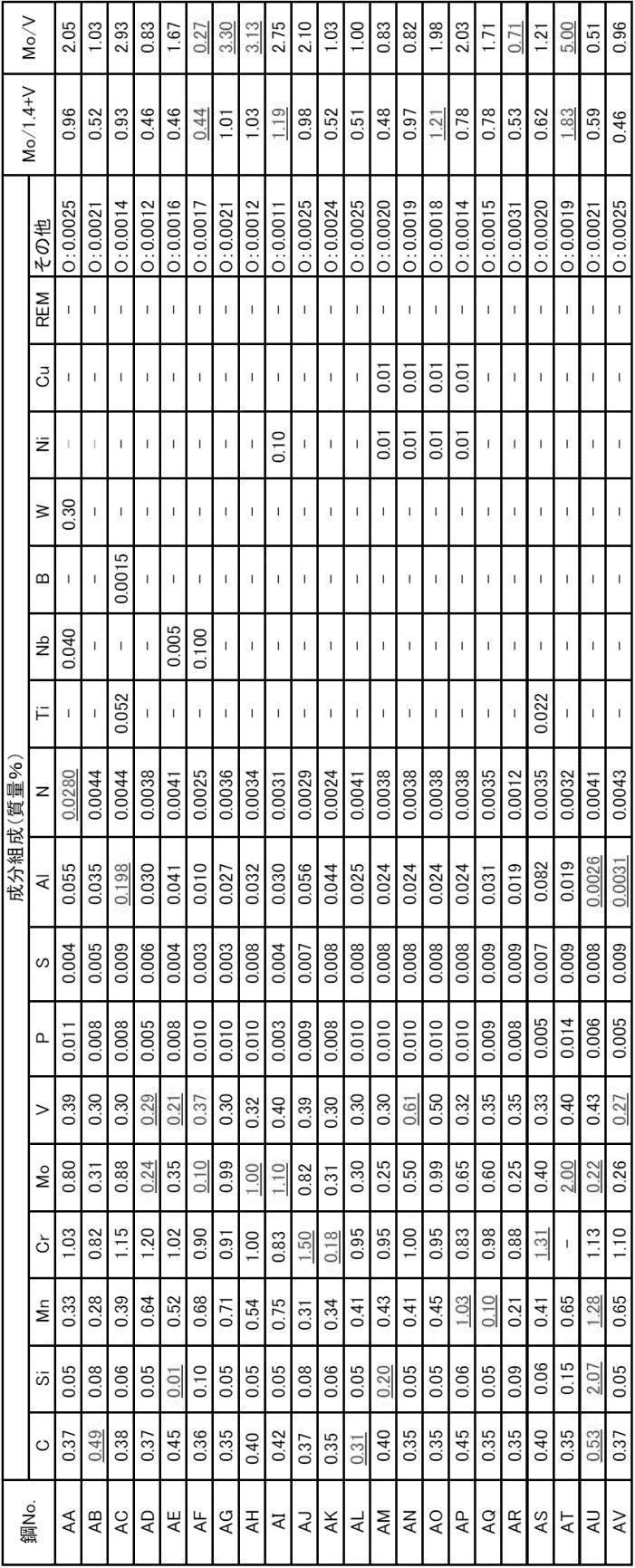
上記のようにして得た直径20mm、長さ1000mmの丸棒を切断し、直径20mm、長さ300mmの丸棒を切り出し、表2に記載の温度で焼入れを行った。焼入れ加熱温度での保持時間は60分とした。その後、60℃に保持した油槽へ焼入れを行った。
油焼入れ後、表2に記載の温度で焼戻しを行った。焼戻し温度での保持時間は60分とし、焼戻し後の冷却は空冷(冷却速度10℃/s)とした。
上記の焼入れ焼戻し処理後の直径20mm、長さ300mmの丸棒から、全長70mm、平行部の直径6mm、長さ32mmの平滑引張試験片(14A号試験片)を採取した。
上記の焼入れ焼戻し処理後の直径20mm、長さ300mmの丸棒から、直径7mm、長さ70mmの丸棒試験片を採取し、トラップ水素量調査用の丸棒試験片とした。
上記の焼入れ焼戻し処理後の直径20mm、長さ300mmの丸棒から、直径7mm、長さ70mmの切欠き(切欠き部の、直径4.2mm、角度60°)付き丸棒試験片を採取し、遅れ破壊試験片とした。
長さ5nm以上のMC型炭化物の個数密度(単位面積0.01μm2当たりの個数)は、既述の通り測定した。そして、次の基準で評価した。
A:MC型炭化物の個数密度が10個/0.01μm2以上14個/0.01μm2未満
B:MC型炭化物の個数密度が15個/0.01μm2以上20個/0.01μm2未満
C:MC型炭化物の個数密度が20個/0.01μm2以上100個/0.01μm2未満
D:MC型炭化物の個数密度が10個/0.01μm2未満
引張強さは、既述の通り測定した。
具体的には、上記の手順で作製した引張試験片を用い、JIS Z 2241:2011に準拠して、室温(25℃)の大気中で引張試験を行い、引張強さを求めた。
トラップ水素量は、既述の通り測定した。
具体的には、上記の手順で作製した直径7mm、長さ70mmの丸棒試験片に、3.0質量%の塩化ナトリウム水溶液1L当たり3.0gのチオシアン酸アンモニウムを添加した室温(25℃)の溶液中で、電流密度0.2mA/cm2で72時間陰極水素チャージを行った。その後、室温で48時間静置した。その後、ガスクロマトグラフを用い、昇温速度100℃/ 時間で、室温(25℃)から400℃まで昇温し、試料から放出される水素量を測定した。
耐水素脆化特性は、既述の通り測定した。
具体的には、上記の手順で作製した直径7mm、長さ70mmの切欠き(切欠き部の、直径4.2mm、角度60°)付き遅れ破壊試験片に、3.0質量%の塩化ナトリウム水溶液1L当たり3.0gのチオシアン酸アンモニウムを添加した室温(25℃)の溶液中で、電流密度0.03mA/cm2で24時間陰極水素チャージした後、水素透過防止めっき(溶融亜鉛めっき)を施し、96時間放置した後、引張強さの0.9倍の一定荷重を負荷し、破断に至るまでの時間を測定した。100時間破断しなかった場合は試験を打ち切りとした。

本明細書に記載された全ての文献、特許出願、および技術規格は、個々の文献、特許出願、および技術規格が参照により取り込まれることが具体的かつ個々に記された場合と同程度に、本明細書中に参照により取り込まれる。
Claims (7)
- 組成が、質量%で、
C :0.35~0.45%、
Si:0.02~0.10%、
Mn:0.20~0.84%、
Cr:0.60~1.15%、
V :0.30~0.50%、
Mo:0.25~0.99%、
Al:0.010~0.100%、
N :0.0010~0.0150%、
P :0.015%以下、
S :0.015%以下、
残部:Fe及び不純物からなり、
かつ、下記式(1)及び下記式(2)を満たし、
引張強さが、1200MPa以上1600MPa未満である
ボルト。
0.48≦Mo/1.4+V<1.10・・・(1)
0.80<Mo/V<3.00 ・・・(2)
但し、式(1)、式(2)において、MoとVには、それぞれ、ボルトが含有するMoとVの含有量(質量%)が代入される。 - Ti:0.100%以下、
Nb:0.100%以下、
B :0.0050%以下、
Ni:0.20%以下、
Cu:0.20%以下、
W :0.50%以下、
REM:0.020%以下、
Sn:0.20以下
Bi:0.10以下
よりなる群から選択される少なくとも1種をさらに含有する、請求項1に記載のボルト。 - Pb:0.05%以下
Cd:0.05%以下
Co:0.05%以下
Zn:0.05%以下
Ca:0.02%以下
Zr:0.02%以下
よりなる群から選択される少なくとも1種をさらに含有する、請求項1又は請求項2に記載のボルト。 - 長さ5nm以上のMC型炭化物であって、M(金属元素)に対しVおよびMoを合計で70原子%以上含むMC型炭化物が、単位面積0.01μm2当たり10個以上存在する、請求項1~請求項3のいずれか1項に記載のボルト。
- 3.0質量%の塩化ナトリウム水溶液1L当たり3.0gのチオシアン酸アンモニウムを添加した室温の溶液中で、電流密度0.2mA/cm2で72時間陰極水素チャージし、室温で48時間静置した後のトラップ水素量が3.0ppm以上である、請求項1~請求項4のいずれか1項に記載のボルト。
- 3.0質量%の塩化ナトリウム水溶液1L当たり3.0gのチオシアン酸アンモニウムを添加した室温の溶液中で、電流密度0.03mA/cm2で24時間陰極水素チャージした後、水素透過防止めっきを施し、96時間放置した後、引張強さの0.9倍の一定荷重を負荷した時の、破断に至るまでの時間が100時間以上である、請求項1~請求項5のいずれか1項に記載のボルト。
- 請求項1~請求項6のいずれか1項に記載のボルトの素材であるボルト用鋼材であって、
前記ボルトの組成および引張強さを有するボルト用鋼材。
Priority Applications (4)
| Application Number | Priority Date | Filing Date | Title |
|---|---|---|---|
| KR1020217022911A KR102556224B1 (ko) | 2019-02-08 | 2020-02-07 | 볼트, 및 볼트용 강재 |
| JP2020571306A JP7188466B2 (ja) | 2019-02-08 | 2020-02-07 | ボルト、及びボルト用鋼材 |
| CN202080012587.1A CN113383094B (zh) | 2019-02-08 | 2020-02-07 | 螺栓以及螺栓用钢材 |
| US17/418,247 US20220064766A1 (en) | 2019-02-08 | 2020-02-07 | Bolt, and steel material for bolts |
Applications Claiming Priority (2)
| Application Number | Priority Date | Filing Date | Title |
|---|---|---|---|
| JP2019-021904 | 2019-02-08 | ||
| JP2019021904 | 2019-02-08 |
Publications (1)
| Publication Number | Publication Date |
|---|---|
| WO2020162616A1 true WO2020162616A1 (ja) | 2020-08-13 |
Family
ID=71947014
Family Applications (1)
| Application Number | Title | Priority Date | Filing Date |
|---|---|---|---|
| PCT/JP2020/004916 Ceased WO2020162616A1 (ja) | 2019-02-08 | 2020-02-07 | ボルト、及びボルト用鋼材 |
Country Status (5)
| Country | Link |
|---|---|
| US (1) | US20220064766A1 (ja) |
| JP (1) | JP7188466B2 (ja) |
| KR (1) | KR102556224B1 (ja) |
| CN (1) | CN113383094B (ja) |
| WO (1) | WO2020162616A1 (ja) |
Cited By (10)
| Publication number | Priority date | Publication date | Assignee | Title |
|---|---|---|---|---|
| JP2022128623A (ja) * | 2021-02-24 | 2022-09-05 | 大同特殊鋼株式会社 | 高強度ボルト用鋼及びその製造方法 |
| JP7231136B1 (ja) * | 2022-05-17 | 2023-03-01 | 日本製鉄株式会社 | 締結部材の素材として用いられる鋼材、及び、締結部材 |
| JP2023090155A (ja) * | 2021-12-17 | 2023-06-29 | 日本製鉄株式会社 | ボルト |
| WO2023167319A1 (ja) * | 2022-03-04 | 2023-09-07 | 日本製鉄株式会社 | 鋼材 |
| JP2024032361A (ja) * | 2022-08-29 | 2024-03-12 | 日本製鉄株式会社 | 鋼材 |
| JP2024040993A (ja) * | 2022-09-13 | 2024-03-26 | 日本製鉄株式会社 | ボルト |
| JP2024040995A (ja) * | 2022-09-13 | 2024-03-26 | 日本製鉄株式会社 | ボルト |
| JP2024040994A (ja) * | 2022-09-13 | 2024-03-26 | 日本製鉄株式会社 | ボルト |
| JP2024521172A (ja) * | 2021-05-28 | 2024-05-28 | バオシャン アイアン アンド スティール カンパニー リミテッド | ボルト用鋼、およびその製造方法 |
| KR20240151817A (ko) | 2022-03-04 | 2024-10-18 | 닛폰세이테츠 가부시키가이샤 | 강재 |
Families Citing this family (4)
| Publication number | Priority date | Publication date | Assignee | Title |
|---|---|---|---|---|
| CN114951573B (zh) * | 2022-04-26 | 2024-04-02 | 江苏省沙钢钢铁研究院有限公司 | 12.9级紧固件用盘条及其生产方法 |
| KR20240038469A (ko) | 2022-09-16 | 2024-03-25 | 김정훈 | 사용자 콘텐츠 기반 홍보 서비스 제공 장치 및 방법 |
| CN116024499B (zh) * | 2022-12-28 | 2024-06-25 | 燕山大学 | 一种抗氢致延迟断裂的10.9级螺栓用钢及10.9级螺栓的制备方法 |
| CN118957429A (zh) * | 2024-09-27 | 2024-11-15 | 邯郸市濮政工矿配件制造有限公司 | 一种高强度桥梁螺栓及其制备方法 |
Citations (3)
| Publication number | Priority date | Publication date | Assignee | Title |
|---|---|---|---|---|
| JPH08225845A (ja) * | 1995-02-20 | 1996-09-03 | Daido Steel Co Ltd | 耐遅れ破壊性に優れた高強度ボルトの製造方法 |
| JP2011047010A (ja) * | 2009-08-27 | 2011-03-10 | Kobe Steel Ltd | 耐遅れ破壊性の改善された高強度ボルト及びその製造方法 |
| JP2012233244A (ja) * | 2011-05-09 | 2012-11-29 | Sumitomo Metal Ind Ltd | 鋼製ボルトおよびその製造方法 |
Family Cites Families (9)
| Publication number | Priority date | Publication date | Assignee | Title |
|---|---|---|---|---|
| JP3358679B2 (ja) | 1994-04-14 | 2002-12-24 | 新日本製鐵株式会社 | 耐遅れ破壊特性に優れた高張力ボルト |
| JP4142853B2 (ja) | 2001-03-22 | 2008-09-03 | 新日本製鐵株式会社 | 耐遅れ破壊特性に優れた高力ボルト |
| JP3905333B2 (ja) * | 2001-07-10 | 2007-04-18 | 株式会社住友金属小倉 | 高強度ボルト用鋼とボルトの製造方法 |
| JP4485424B2 (ja) | 2005-07-22 | 2010-06-23 | 新日本製鐵株式会社 | 耐遅れ破壊特性に優れた高強度ボルトの製造方法 |
| JP5353501B2 (ja) * | 2008-07-09 | 2013-11-27 | 新日鐵住金株式会社 | 耐水素性に優れた常温高圧水素ガス貯蔵鋼製容器およびその製造方法 |
| JP5760972B2 (ja) | 2011-11-10 | 2015-08-12 | 新日鐵住金株式会社 | 耐遅れ破壊特性に優れた高強度ボルト鋼および高強度ボルト |
| JP6190298B2 (ja) * | 2014-03-25 | 2017-08-30 | 株式会社神戸製鋼所 | 耐遅れ破壊性に優れた高強度ボルト用鋼および高強度ボルト |
| JP6461672B2 (ja) * | 2015-03-27 | 2019-01-30 | 株式会社神戸製鋼所 | 冷間圧造性、および焼入れ焼戻し後の耐遅れ破壊性に優れたボルト用鋼線、並びにボルト |
| KR101867689B1 (ko) * | 2016-09-01 | 2018-06-15 | 주식회사 포스코 | 수소취성 저항성이 우수한 고강도 스프링용 강재 및 그 제조방법 |
-
2020
- 2020-02-07 WO PCT/JP2020/004916 patent/WO2020162616A1/ja not_active Ceased
- 2020-02-07 KR KR1020217022911A patent/KR102556224B1/ko active Active
- 2020-02-07 US US17/418,247 patent/US20220064766A1/en not_active Abandoned
- 2020-02-07 CN CN202080012587.1A patent/CN113383094B/zh active Active
- 2020-02-07 JP JP2020571306A patent/JP7188466B2/ja active Active
Patent Citations (3)
| Publication number | Priority date | Publication date | Assignee | Title |
|---|---|---|---|---|
| JPH08225845A (ja) * | 1995-02-20 | 1996-09-03 | Daido Steel Co Ltd | 耐遅れ破壊性に優れた高強度ボルトの製造方法 |
| JP2011047010A (ja) * | 2009-08-27 | 2011-03-10 | Kobe Steel Ltd | 耐遅れ破壊性の改善された高強度ボルト及びその製造方法 |
| JP2012233244A (ja) * | 2011-05-09 | 2012-11-29 | Sumitomo Metal Ind Ltd | 鋼製ボルトおよびその製造方法 |
Cited By (17)
| Publication number | Priority date | Publication date | Assignee | Title |
|---|---|---|---|---|
| JP7697222B2 (ja) | 2021-02-24 | 2025-06-24 | 大同特殊鋼株式会社 | 高強度ボルト用鋼及びその製造方法 |
| JP2022128623A (ja) * | 2021-02-24 | 2022-09-05 | 大同特殊鋼株式会社 | 高強度ボルト用鋼及びその製造方法 |
| JP2024521172A (ja) * | 2021-05-28 | 2024-05-28 | バオシャン アイアン アンド スティール カンパニー リミテッド | ボルト用鋼、およびその製造方法 |
| JP7728363B2 (ja) | 2021-05-28 | 2025-08-22 | バオシャン アイアン アンド スティール カンパニー リミテッド | ボルト用鋼、およびその製造方法 |
| JP2023090155A (ja) * | 2021-12-17 | 2023-06-29 | 日本製鉄株式会社 | ボルト |
| JP7695553B2 (ja) | 2021-12-17 | 2025-06-19 | 日本製鉄株式会社 | ボルト |
| KR20240151817A (ko) | 2022-03-04 | 2024-10-18 | 닛폰세이테츠 가부시키가이샤 | 강재 |
| KR20240146676A (ko) | 2022-03-04 | 2024-10-08 | 닛폰세이테츠 가부시키가이샤 | 강재 |
| JPWO2023167319A1 (ja) * | 2022-03-04 | 2023-09-07 | ||
| WO2023167319A1 (ja) * | 2022-03-04 | 2023-09-07 | 日本製鉄株式会社 | 鋼材 |
| WO2023223409A1 (ja) * | 2022-05-17 | 2023-11-23 | 日本製鉄株式会社 | 締結部材の素材として用いられる鋼材、及び、締結部材 |
| JP7231136B1 (ja) * | 2022-05-17 | 2023-03-01 | 日本製鉄株式会社 | 締結部材の素材として用いられる鋼材、及び、締結部材 |
| JP2024032361A (ja) * | 2022-08-29 | 2024-03-12 | 日本製鉄株式会社 | 鋼材 |
| JP7827990B2 (ja) | 2022-08-29 | 2026-03-11 | 日本製鉄株式会社 | 鋼材 |
| JP2024040993A (ja) * | 2022-09-13 | 2024-03-26 | 日本製鉄株式会社 | ボルト |
| JP2024040995A (ja) * | 2022-09-13 | 2024-03-26 | 日本製鉄株式会社 | ボルト |
| JP2024040994A (ja) * | 2022-09-13 | 2024-03-26 | 日本製鉄株式会社 | ボルト |
Also Published As
| Publication number | Publication date |
|---|---|
| US20220064766A1 (en) | 2022-03-03 |
| JPWO2020162616A1 (ja) | 2021-11-11 |
| CN113383094A (zh) | 2021-09-10 |
| CN113383094B (zh) | 2023-08-15 |
| JP7188466B2 (ja) | 2022-12-13 |
| KR20210104862A (ko) | 2021-08-25 |
| KR102556224B1 (ko) | 2023-07-18 |
Similar Documents
| Publication | Publication Date | Title |
|---|---|---|
| JP7188466B2 (ja) | ボルト、及びボルト用鋼材 | |
| CN101365820B (zh) | 抗脆断性能优异的高强度弹簧钢及其制造方法 | |
| JP4712882B2 (ja) | 耐水素脆化特性および加工性に優れた高強度冷延鋼板 | |
| JP7464832B2 (ja) | ボルト、及びボルト用鋼材 | |
| JIANG et al. | Aging precipitation behavior of 18Cr-16Mn-2Mo-1. 1N high nitrogen austenitic stainless steel and its influences on mechanical properties | |
| CN109790602B (zh) | 钢 | |
| JP7457234B2 (ja) | ボルト及びボルトの製造方法 | |
| JP7164032B2 (ja) | ボルト、及びボルト用鋼材 | |
| JP6436232B2 (ja) | ばね鋼 | |
| JP6399213B2 (ja) | 肌焼鋼部品 | |
| WO2010109702A1 (ja) | 冷延鋼板 | |
| JP7273295B2 (ja) | ボルト用鋼、ボルト、及びボルトの製造方法 | |
| JP2012017484A (ja) | ボルト用鋼、ボルトおよびボルトの製造方法 | |
| JP6648659B2 (ja) | 機械構造用部品 | |
| KR101899739B1 (ko) | 연질화 처리용 강판 및 그 제조 방법과 연질화 처리 강 | |
| KR20190034252A (ko) | 블레이드용 소재 | |
| JP7337486B2 (ja) | 鋼材およびその製造方法 | |
| JP2017210645A (ja) | 高強度鋼 | |
| JPH1036940A (ja) | 耐遅れ破壊性に優れた高強度ボルト用鋼およびボルト | |
| JP7168101B2 (ja) | 高強度鋼部材 | |
| KR20240034213A (ko) | 페라이트계 내열강 |
Legal Events
| Date | Code | Title | Description |
|---|---|---|---|
| 121 | Ep: the epo has been informed by wipo that ep was designated in this application |
Ref document number: 20752484 Country of ref document: EP Kind code of ref document: A1 |
|
| ENP | Entry into the national phase |
Ref document number: 2020571306 Country of ref document: JP Kind code of ref document: A |
|
| ENP | Entry into the national phase |
Ref document number: 20217022911 Country of ref document: KR Kind code of ref document: A |
|
| NENP | Non-entry into the national phase |
Ref country code: DE |
|
| 122 | Ep: pct application non-entry in european phase |
Ref document number: 20752484 Country of ref document: EP Kind code of ref document: A1 |