WO2020162528A1 - 端末装置、方法、および、集積回路 - Google Patents
端末装置、方法、および、集積回路 Download PDFInfo
- Publication number
- WO2020162528A1 WO2020162528A1 PCT/JP2020/004488 JP2020004488W WO2020162528A1 WO 2020162528 A1 WO2020162528 A1 WO 2020162528A1 JP 2020004488 W JP2020004488 W JP 2020004488W WO 2020162528 A1 WO2020162528 A1 WO 2020162528A1
- Authority
- WO
- WIPO (PCT)
- Prior art keywords
- information
- rrc
- message
- rrc connection
- inactive
- Prior art date
- Legal status (The legal status is an assumption and is not a legal conclusion. Google has not performed a legal analysis and makes no representation as to the accuracy of the status listed.)
- Ceased
Links
Images


Classifications
-
- H—ELECTRICITY
- H04—ELECTRIC COMMUNICATION TECHNIQUE
- H04W—WIRELESS COMMUNICATION NETWORKS
- H04W48/00—Access restriction; Network selection; Access point selection
- H04W48/16—Discovering, processing access restriction or access information
-
- H—ELECTRICITY
- H04—ELECTRIC COMMUNICATION TECHNIQUE
- H04W—WIRELESS COMMUNICATION NETWORKS
- H04W76/00—Connection management
- H04W76/20—Manipulation of established connections
-
- H—ELECTRICITY
- H04—ELECTRIC COMMUNICATION TECHNIQUE
- H04W—WIRELESS COMMUNICATION NETWORKS
- H04W48/00—Access restriction; Network selection; Access point selection
- H04W48/20—Selecting an access point
-
- H—ELECTRICITY
- H04—ELECTRIC COMMUNICATION TECHNIQUE
- H04W—WIRELESS COMMUNICATION NETWORKS
- H04W76/00—Connection management
- H04W76/20—Manipulation of established connections
- H04W76/27—Transitions between radio resource control [RRC] states
-
- H—ELECTRICITY
- H04—ELECTRIC COMMUNICATION TECHNIQUE
- H04W—WIRELESS COMMUNICATION NETWORKS
- H04W76/00—Connection management
- H04W76/30—Connection release
-
- H—ELECTRICITY
- H04—ELECTRIC COMMUNICATION TECHNIQUE
- H04W—WIRELESS COMMUNICATION NETWORKS
- H04W88/00—Devices specially adapted for wireless communication networks, e.g. terminals, base stations or access point devices
- H04W88/02—Terminal devices
Definitions
- the present invention relates to a terminal device, a method, and an integrated circuit.
- the present application claims priority based on Japanese Patent Application No. 2019-20709 filed in Japan on February 7, 2019, the contents of which are incorporated herein by reference.
- a wireless access method and wireless network of cellular-mobile communication (hereinafter, referred to as “Long Term Evolution (LTE: registered trademark)” or “Evolved Universal Terrestrial Radio Access: EUTRA”), and a core network (hereinafter, “Evolved”).
- LTE Long Term Evolution
- EUTRA Evolved Universal Terrestrial Radio Access
- EPC Packet Core
- LTE-Advanced Pro which is an extension technology of LTE
- NR New Radio technology
- 5GC 5 Generation Core Network
- 3GPP RP-170855 "Work Item on New Radio (NR) Access Technology” 3GPP TS 23.501 v15.3.0, "System Architecture for the 5G System; Stage 2" 3GPP TS 36.300, v15.3.0, “Evolved Universal Terrestrial Radio Access (E-UTRA) and Evolved Universal Terrestrial OTR Network; 3GPP TS 36.331 v15.3.0, “Evolved Universal Terrestrial Radio Access (E-UTRA); Radio Resource Control (RRC); Protocol Specifications” 3GPP TS 36.323 v15.3.0, “Evolved Universal Terrestrial Radio Access (E-UTRA); Packet Data Convergence Protocol (PDCP) specification” 3GPP TS 36.322 v15.3.0, “Evolved Universal Terrestrial Radio Access (E-UTRA); Radio Link Control (RLC) protocol specification” 3GPP TS 36.321 v15.3.0, “Evolved Universal Terrestrial Radio Access (E
- the inactive state (also called RRC_INACTIVE or RRC_INACTIVE state) has been introduced.
- the inactive state is a state in which a specific area (RAN notification area: RNA) set in the RAN can be moved without notifying the RAN while maintaining the connection with the core network.
- the terminal device transits between the inactive state, the idle state (also referred to as RRC_IDLE, RRC_IDLE state) which is a standby state, and the connection state (also referred to as RRC_CONNECTED, RRC_CONNECTED state) based on the predetermined conditions.
- the terminal device holds or discards various parameters based on a predetermined condition (Non-Patent Document 18).
- One aspect of the present invention has been made in view of the above circumstances, and is a terminal device capable of efficiently performing cell selection and/or reselection of a terminal device, a method used for the terminal device, and the terminal device. It is an object of the present invention to provide an integrated circuit mounted on.
- a first aspect of the present invention is a terminal device, which transmits a first message requesting a return (resume) from an inactive state to a connected state, and a priority for cell selection.
- the control includes: a reception unit that receives a second message that includes information (first information) and that instructs transition to an idle state (connection release); and a control unit that holds the first information.
- the unit retains the first information when retaining the first information, based on whether the transition from the inactive state to the idle state is triggered by the reception of the second message. Decide whether to discard or
- a second aspect of the present invention is a method applied to a terminal device, including a step of transmitting a first message requesting a return (resume) from an inactive state to a connected state, and cell selection.
- Receiving a second message instructing a transition to an idle state (release of a connection) the priority message including priority information (first information), and holding the first information.
- the first information when the control unit holds the first information based on whether the transition from the inactive state to the idle state is triggered by the reception of the second message. Determines whether to keep or destroy.
- a third aspect of the present invention is an integrated circuit mounted in a terminal device, which has a function of transmitting a first message requesting a return (resume) from an inactive state to a connected state, and a cell.
- the control unit holds the first information based on whether or not the transition from the inactive state to the idle state is triggered by the reception of the second message. If so, it is determined whether to retain or discard the first information.
- the terminal device can efficiently perform cell selection and/or reselection based on optimum parameter settings.
- FIG. 1 is a schematic diagram of a communication system according to an embodiment of the present invention.
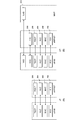
- FIG. 3 is a protocol stack diagram of UP and CP of a terminal device and a base station device in E-UTRA according to the embodiment of the present invention.
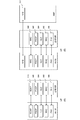
- FIG. 3 is a protocol stack diagram of UP and CP of a terminal device and a base station device in NR according to the embodiment of the present invention.
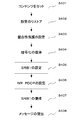
- the figure which shows an example of the flow of the transmission process of the RRC connection restoration request (RRCConnectionResumeRequest) message in embodiment of this invention.
- the block diagram which shows the structure of the terminal device in embodiment of this invention.
- the block diagram which shows the structure of the base station apparatus in embodiment of this invention.
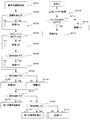
- movement of a terminal device when receiving the RRC connection release message in embodiment of this invention shows an example of the flow of operation
- LTE (and LTE-A Pro) and NR may be defined as different RATs.
- NR may also be defined as a technology included in LTE.
- LTE may be defined as a technology included in NR.
- LTE that can be connected by NR and Multi RAT Dual connectivity may be distinguished from conventional LTE.
- LTE in which the core network is 5GC may be distinguished from conventional LTE in which the core network is EPC.
- E-UTRA in this embodiment may be replaced with the term LTE, and the term LTE may be replaced with the term E-UTRA.
- FIG. 1 is a schematic diagram of a communication system according to each embodiment of the present invention.
- E-UTRA100 is a radio access technology described in Non-Patent Document 3 and the like, and is composed of a cell group (Cell Group: CG) configured by one or a plurality of frequency bands.
- the eNB (E-UTRAN Node B) 102 is a base station device of the E-UTRA 100.
- EPC (Evolved Packet Core) 104 is a core network described in Non-Patent Document 14 and the like, and was designed as a core network for E-UTRA100.
- the interface 112 is an interface between the eNB 102 and the EPC 104, and includes a control plane (Control Plane: CP) through which a control signal passes and a user plane (User Plane: UP) through which the user data passes.
- Control Plane: CP Control Plane
- User Plane: UP User Plane
- NR106 is a radio access technology described in Non-Patent Document 9 and the like, and is composed of a cell group (Cell Group: CG) configured by one or a plurality of frequency bands.
- the gNB (g Node B) 108 is a base station device of the NR 106.
- the 5GC 110 is a core network described in Non-Patent Document 2 and the like, and is designed as a core network for the NR 106, but may be used as a core network for the E-UTRA 100 having a function of connecting to the 5GC 110.
- the E-UTRA 100 may include the E-UTRA 100 having a function of connecting to the 5GC 110.
- the interface 114 is the interface between the eNB 102 and the 5GC 110
- the interface 116 is the interface between the gNB 108 and the 5GC 110
- the interface 118 is the interface between the gNB 108 and the EPC 104
- the interface 120 is the interface between the eNB 102 and the gNB 108
- the interface 124 is the EPC 104 and the 5GC 110. Is an interface between.
- the interface 114, the interface 116, the interface 118, the interface 120, the interface 124, and the like may be CP-only, UP-only, or interfaces that pass both CP and UP. Further, the interface 114, the interface 116, the interface 118, the interface 120, the interface 124, and the like may not exist depending on the communication system provided by the communication carrier.
- UE122 is a terminal device that supports NR106 or both E-UTRA100 and NR106.
- a radio bearer (RB: Radio Bearer)
- SRB Signaling Radio Bearer
- DRB Data Radio Bearer The radio bearer used for CP is called a signaling radio bearer (SRB: Signaling Radio Bearer), and the radio bearer used for UP is called a data radio bearer (DRB Data Radio Bearer).
- An RB identifier (RB Identity, or RB ID) is assigned to each RB and uniquely identified.
- the RB identifier for SRB is called SRB identifier (SRB Identity, or SRB ID)
- the RB identifier for DRB is called DRB identifier (DRB Identity, or DRB ID).
- each DRB established between the UE 122 and the E-UTRA 100, and/or the NR 106 further passes through the EPC 104. It is uniquely associated with an EPS (Evolved Packet System) bearer.
- An EPS bearer identifier (Identity, or ID) is assigned to each EPS bearer and uniquely identified. Further, the same QoS is guaranteed for the data passing through the same EPS bearer.
- one or more DRBs established between the UE122 and the E-UTRA100 and/or the NR106 are further included in the 5GC110.
- PDU Packet Data Unit
- Each DRB may be associated (map) with one or a plurality of QoS flows existing in the associated PDU session, or may not be associated with any QoS flow.
- Each PDU session is identified by a PDU session identifier (Identity, or ID). Further, each QoS flow is identified by a QoS flow identifier. Further, the same QoS is guaranteed for the data passing through the same QoS flow.
- PDU session and/or QoS flow does not exist in EPC104, and EPS bearer does not exist in 5GC110.
- the UE 122 when the UE 122 is connected to the EPC 104, the UE 122 has information on the EPS bearer, and when the UE 122 is connected to the 5GC 110, the UE 122 has information on the PDU session and/or the QoS flow.
- FIG. 2 is a protocol stack diagram of UP and CP of the terminal device and the base station device in the E-UTRA radio access layer in each embodiment of the present invention.
- FIG. 2A is a protocol stack diagram of the UP used when the UE 122 in the E-UTRA 100 communicates with the eNB 102.
- the PHY (Physical layer) 200 is a wireless physical layer (wireless physical layer) and provides a transmission service to an upper layer (upper layer) using a physical channel (Physical Channel).
- the PHY 200 is connected to a higher-level MAC (Medium Access Control layer) 202, which will be described later, by a transport channel (Transport Channel). Data moves between the MAC 202 and the PHY 200 via the transport channel. Data is transmitted and received between the UE 122 and the PHY of the eNB 102 via a wireless physical channel.
- the MAC 202 is a medium access control layer (medium access control layer) that maps various logical channels (Logical Channels) to various transport channels.
- the MAC 202 is connected to a higher-order RLC (Radio Link Control layer) 204 described later by a logical channel.
- Logical channels are roughly classified according to the type of information to be transmitted, and are classified into a control channel for transmitting control information and a traffic channel for transmitting user information.
- the MAC 202 has a function of controlling the PHY 200 for performing discontinuous transmission (DRX/DTX), a function of executing a random access (Random Access) procedure, a function of notifying transmission power information, a function of performing HARQ control, and the like.
- DRX/DTX discontinuous transmission
- Random Access random access
- the RLC 204 divides the data received from the higher-order PDCP (Packet Data Convergence Protocol Layer) 206 described later, and adjusts the data size so that the lower layer (lower layer) can appropriately transmit the data.
- Wireless link control layer radio link control layer
- the RLC 200 also has a function for guaranteeing the QoS (Quality of Service) required by each data. That is, the RLC 204 has functions such as data retransmission control (Non-Patent Document 6).
- the PDCP 206 is a packet data convergence protocol layer (packet data convergence protocol layer) for efficiently transmitting an IP packet (IP Packet) that is user data in a wireless section.
- the PDCP 206 may have a header compression function that compresses unnecessary control information.
- the PDCP 206 may also have a data encryption function (Non-Patent Document 5).
- the data processed by the MAC 202, RLC 204, and PDCP 206 are called MAC PDU (Protocol Data Unit), RLC PDU, and PDCP PDU, respectively.
- the data passed from the upper layer to the MAC 202, RLC 204, PDCP 206, or the data passed to the upper layer are called MAC SDU (Service Data Unit), RLC SDU, and PDCP SDU, respectively.
- FIG. 2B is a protocol stack diagram of the CP used when the UE 122 in the E-UTRA 100 communicates with the eNB 102 and the MME (Mobility Management Entity) that is a logical node that provides functions such as authentication and mobility management. ..
- MME Mobility Management Entity
- the RRC 208 performs processes such as establishment, re-establishment, suspension (suspend), and suspension release (resume) of RRC connection, and reconfiguration of RRC connection, for example, radio bearer (Radio Bearer: RB) and cell group (Cell Group). Radio link control layer (radio link control) for establishing, changing, releasing, etc., controlling logical channels, transport channels, and physical channels, as well as setting handover and measurement (measurement). Layer).
- the RB may be divided into a signaling radio bearer (Signaling Radio Bearer: SRB) and a data radio bearer (Data Radio Bearer: DRB), and the SRB is used as a route for transmitting an RRC message that is control information. May be.
- the DRB may be used as a route for transmitting user data.
- Each RB may be set between the RRC 208 of the eNB 102 and the UE 122. Further, a part of the RB configured by the RLC 204 and the MAC 202 may be called an RLC bearer (Non-Patent Document 4).
- some or all layers of the PHY 200, the MAC 202, the RLC 204, the PDCP 206, and the RRC 208 that carry the signal between the UE 122 and the eNB 102 may be AS (Access). Strarum) layer.
- the above-mentioned function classification of the MAC 202, RLC 204, PDCP 206, and RRC 208 is an example, and some or all of the functions may not be implemented. Further, some or all of the functions of each layer may be included in another layer.
- the IP layer and the TCP (Transmission Control Protocol) layer, the UDP (User Datagram Protocol) layer, and the application layer above the IP layer are upper layers of the PDCP layer (not shown).
- the RRC layer and the NAS (non Access Stratum) layer are also upper layers of the SDAP layer (not shown).
- the PDCP layer is a lower layer of the RRC layer, the NAS layer, the IP layer, and the TCP (Transmission Control Protocol) layer, the UDP (User Datagram Protocol) layer, and the application layer above the IP layer.
- FIG. 3 is a protocol stack diagram of UP and CP of the terminal device and the base station device in the NR radio access layer in each embodiment of the present invention.
- 3A is a protocol stack diagram of the UP used when the UE 122 communicates with the gNB 108 in the NR 106.
- the PHY (Physical layer) 300 is an NR wireless physical layer (wireless physical layer), and may provide a transmission service to an upper layer using a physical channel (Physical Channel).
- the PHY 300 may be connected to a higher-level MAC (Medium Access Control layer) 302, which will be described later, by a transport channel (Transport Channel). Data may move between the MAC 302 and the PHY 300 via the transport channel. Data may be transmitted and received between the PHY of the UE 122 and the gNB 108 via a wireless physical channel.
- the MAC 302 is a medium access control layer (medium access control layer) that maps various logical channels (Logical Channels) to various transport channels.
- the MAC 302 may be connected to a higher-level RLC (Radio Link Control layer) 304 described later by a logical channel.
- the logical channel is roughly classified according to the type of information to be transmitted, and may be divided into a control channel for transmitting control information and a traffic channel for transmitting user information.
- the MAC 302 has a function of controlling the PHY 300 for performing discontinuous transmission (DRX/DTX), a function of executing a random access (Random Access) procedure, a function of notifying transmission power information, a function of performing HARQ control, and the like. You may have (nonpatent literature 13).
- the RLC 304 divides the data received from a higher-order PDCP (Packet Data Convergence Protocol Layer) 206 described later (Segmentation), and adjusts the data size so that the lower layer can appropriately transmit the data. It is a layer (radio link control layer).
- the RLC 304 may also have a function of guaranteeing the QoS (Quality of Service) required by each data. That is, the RLC 304 may have a function such as data retransmission control (Non-Patent Document 12).
- the PDCP 306 is a packet data convergence protocol layer (packet data convergence protocol layer) that efficiently transmits an IP packet (IP Packet) that is user data in a wireless section.
- the PDCP 306 may have a header compression function that compresses unnecessary control information.
- the PDCP 306 may also have a data encryption function (Non-Patent Document 11).
- the SDAP (Service Data Adaptation Protocol) 310 associates the downlink QoS flow and DRB sent from the 5GC 110 to the terminal device via the base station device (mapping), and the terminal device via the base station device. It is a service data adaptation protocol layer (service data adaptation protocol layer) having a function of performing mapping between an uplink QoS flow sent to the 5GC 110 and a DRB and storing mapping rule information (non-patent document 16).
- service data adaptation protocol layer service data adaptation protocol layer having a function of performing mapping between an uplink QoS flow sent to the 5GC 110 and a DRB and storing mapping rule information (non-patent document 16).
- FIG. 3B is a protocol stack diagram of the CP used when the UE 122 communicates with the gNB 108 and the AMF (Access and Mobility Management function) that is a logical node that provides functions such as authentication and mobility management in the NR 106. ..
- AMF Access and Mobility Management function
- RRC Radio Resource Control layer
- NAS Non Access Stratum
- the RRC 308 performs processing such as establishment, re-establishment, suspension (suspend) and suspension cancellation (resume) of the RRC connection, and reconfiguration of the RRC connection, for example, radio bearer (Radio Bearer: RB) and cell group (Cell Group).
- Radio link control layer radio link control
- Radio link control for establishing, changing, releasing, etc., controlling logical channels, transport channels, and physical channels, as well as setting handover and measurement (measurement). Layer).
- the RB may be divided into a signaling radio bearer (Signaling Radio Bearer: SRB) and a data radio bearer (Data Radio Bearer: DRB), and the SRB is used as a route for transmitting an RRC message that is control information. May be.
- the DRB may be used as a route for transmitting user data.
- Each RB may be set between the gNB 108 and the RRC 308 of the UE 122. Further, a part of the RB that is composed of the RLC 304 and the MAC 302 may be called an RLC bearer (Non-Patent Document 10).
- the NAS layer that carries the signal between the AMF and the UE 122
- some or all layers of the PHY 200, the MAC 202, the RLC 204, the PDCP 206, and the RRC 208 that carry the signal between the UE 122 and the gNB 108 are AS (Access). Strarum) layer.
- MAC 302, RLC 304, PDCP 306, SDAP 310, and RRC 308 is an example, and some or all of the respective functions may not be implemented. Further, some or all of the functions of each layer (each layer) may be included in another layer (layer).
- each layer set in the terminal device and/or (and/or) base station device may be called an entity. That is, the MAC layer, the RLC layer, the PDCP layer, the SDAP layer, and the RRC layer, which are set in the terminal device and/or the base station device, are the MAC entity, the RLC entity, the PDCP entity, the SDAP entity, and the RRC entity. You can call each one.
- the MAC 202, RLC 204, PDCP 206, and RRC 208 are referred to as E-UTRA MAC or LTE MAC and E-UTRA, respectively.
- RLC for LTE or RLC for LTE PDCP for E-UTRA or PDCP for LTE
- RRC for E-UTRA or RRC for LTE.
- the MAC 302, RLC 304, PDCP 306, and RRC 308 may be referred to as an NR MAC, an NR RLC, an NR RLC, and an NR RRC, respectively.
- it may be described using a space such as E-UTRA PDCP or LTE PDCP, NR PDCP.
- the eNB 102, gNB 108, EPC 104, and 5GC 110 may be connected via the interface 112, the interface 116, the interface 118, the interface 120, and the interface 114. Therefore, the RRC 208 of FIG. 2 may be replaced with the RRC 308 of FIG. 3 to support various communication systems.
- the PDCP 206 of FIG. 2 may be replaced with the PDCP 306 of FIG.
- the RRC 308 of FIG. 3 may include the function of the RRC 208 of FIG.
- the PDCP 306 of FIG. 3 may be the PDCP 206 of FIG.
- the NR PDCP may be used as the PDCP even when the UE 122 communicates with the eNB 102.
- the UE 122 may be in the RRC_CONNECTED state when an RRC connection is established (RRC connection has been established). Also, the UE 122 may be in the RRC_INACTIVE state (if the UE 122 is connected to 5GC) when the RRC connection is dormant. If not in those cases, the UE 122 may be in the RRC_IDLE state.
- the UE 122 connected to the EPC does not have the RRC_INACTIVE state, but the suspension of the RRC connection may be started by the E-UTRAN.
- the UE 122 transits to the RRC_IDLE state while holding the AS context of the UE and the identifier (resumeIdentity) used for the return.
- RRC paused when UE 122 holds the AS context of the UE RRC connection reversion is allowed by E-UTRAN, and UE 122 needs to transition from RRC_IDLE state to RRC_CONNECTED state.
- the resumption of connection may be initiated by higher layers (eg NAS layer).
- the definition of sleep may be different between the UE 122 connected to the EPC and the UE 122 connected to the 5GC.
- the UE 122 when it is connected to the EPC (when it is in the RRC_IDLE state and is suspended) and when it is connected to the 5GC (when it is in the RRC_INACTIVE state and is in the suspended state), all of the procedures for returning from the sleep state or Some may be different.
- the AS context of the UE held by the UE 122 is the current RRC setting, the current security context, the PDCP state including the ROHC (RObust Header Compression) state, the C-RNTI used in the PCell of the connection source (Source), and the cell identifier.
- the information may include all or part of (cellIdentity) and the physical cell identifier of the connection source PCell.
- the AS context of the UE held by the eNB 102 and/or the gNB 108 may include the same information as the AS context of the UE held by the UE 122, or information different from the information included in the AS context of the UE held by the UE 122 may be included. May be included.
- the security context is the encryption key at the AS level, the NH (Next Hop parameter), the NCC (Next Hop Chaining Counter parameter) used to derive the access key of the next hop, the identifier of the selected AS level encryption algorithm, and the replay protection.
- the information may include all or some of the counters used for.
- RRC radio resource control
- This procedure may be used to move the UE 122 from RRC_INACTIVE to RRC_CONNECTED. This procedure is performed when there is a request from the upper layer of the RRC to restore the RRC connection, or when the RRC notifies the network that the RNA has changed due to cell reselection (RNA update), or RRC_INACTIVE. UE 122 may have requested RRC connection resumption due to receiving RAN paging).
- the UE 122 stops the timer T380 used to trigger the process of the RNA update, and starts the process of transmitting the RRC connection return request (RRCConnectionResumeRequest) message described below.
- the UE 122 sets the content included in the RRC connection return request message as follows (step S401).
- the complete I-RNTI (fullI-RNTI) that is provided during the Suspend and is stored (Store). Set the value of to fullI-RNTI. Otherwise, shortI-RNTI is set to the value of the short I-RNTI (shortI-RNTI) provided and stored (Suspend).
- the complete I-RNTI is an identifier used to identify a dormant UE context of the RRC_INACTIVE UE 122, and may be, for example, 40-bit information.
- the short I-RNTI is also an identifier used to identify the dormant UE context of the RRC_INACTIVE UE 122, but uses a smaller number of bits than the full I-RNTI.
- the short I-RNTI may be 24 bits of information.
- the UE context here is information regarding the UE 122 held in the network, and may include information regarding the capability regarding the security of the UE 122 and information regarding the capability regarding radio.
- resumeCause is information indicating the reason for restoration included in the RRC connection restoration request message.
- “resumeCause” includes “emergency” indicating an emergency call and "rna-Update” indicating a return for updating RNA.
- the shortResumeMAC-I is information used as an authentication token for facilitating the authentication of the UE 122 by the eNB 102 and/or the gNB 108.
- step S402 except for the PHY and MAC settings, the RRC settings and security context are restored from the retained AS context of the UE (step S402).
- UE122 submits (Submit) the RRC connection return request message to the lower layer for transmission (step S408).
- An RRC connection return message, an RRC connection setup message, an RRC connection reject message, an RRC connection release message, etc. may be sent from the eNB 102 or gNB 108 to the UE 122 as a reply to the RRC connection return request message.
- the eNB 102 or the gNB 108 may send an RRC connection return message to the UE 122 in order to return the UE 122 to the connected state.
- the eNB 102 or the gNB 108 may send an RRC connection setup message to the UE 122 in order to cause the UE 122 to establish the connection state instead of returning it.
- the eNB 102 or the gNB 108 may send an RRC connection rejection message to the UE 122 in order to return the UE 122 to the inactive state.
- the eNB 102 or gNB 108 may also send an RRC connection release message to the UE 122 to put the UE 122 into an idle state.
- the UE 122 receives the RRC connection release message for a predetermined time (for example, 60 ms), or notifies from the lower layer that the response to the RRC connection release message is normally completed, whichever is earlier, and The operation may be delayed (step S701).
- a predetermined time for example, 60 ms
- the process 1A shown below is performed. If not, the process 1A is not performed and the process proceeds to step S704. S702).
- the redirectedCarrierInfo is, for example, information indicating the carrier frequency (downlink in FDD) and the type of the target RAT (eg EUTRA, GERAN, UTRA-FDD, UTRA-TDD, NR release 15, etc.). Good.
- the freqPriorityListGERAN may be, for example, information indicating cell reselection priority information of each frequency in GERAN.
- the idleModeMobilityControlInfo may provide, for example, information on the cell reselection priority individually to the UE 122, and may be used for the cell reselection of the UE 122.
- Process 1A If AS security is not activated, and the upper layer indicates that it does not allow redirecting to GERAN without AS security, or if UE 122 is connected to 5GC, then the RRC connection release message The content is disregarded, the release reason is set to "other", the operation (first operation) when leaving RRC_CONNECTED or RRC_INACTIVE shown below is executed, and this procedure is ended (step S703).
- step S706 step S704.
- Process 1B If the redirect to NR is instructed, the content of redirectedCarrierInfo is ignored. If the idleModeMobilityControlInfo contains the freqPriorityListNR, the contents of idleModeMobilityControlInfo are ignored. If the UE 122 ignores the contents of the redirectedCarrierInfo or the idleModeMobilityControlInfo, the release reason is set to "other" and the first operation described later is executed to end this procedure (step S705).
- the freqPriorityListNR may be, for example, information indicating cell reselection priority information of each frequency in NR.
- the RRC connection release message includes the redirectedCarrierInfo indicating the redirection to EUTRA and the UE 122 is connected to 5GC, the following process 1C is performed, and if not, the process proceeds to step S708 without performing the process 1C ( Step S706).
- Process 1C If the RRC connection release message includes cn-Type, the received cn-Type is provided to the upper layer (step S707).
- process 1D shown below is performed, and if not, process 1E is performed (step S708).
- Process 1D Hold cell reselection priority information provided by idleModeMobilityControlInfo included in the RRC connection release message. If the RRC connection release message includes t320, the timer T320 is started with the value of the timer set according to the value of this t320 (step S709).
- the timer T320 may be a timer used for managing the period in which the cell reselection priority information individually notified to the UE 122 is applied, and may be started when t320 is received. Further, the timer T320 may be started under other conditions. Timer T320 may be stopped when RRC_CONNECTED is entered. The timer T320 may be stopped under other conditions. When the timer T320 expires, that is, when the timer T320 starts and a predetermined time (for example, t320) elapses, the cell reselection priority information individually notified to the UE 122 may be discarded.
- a predetermined time for example, t320
- Process 1E Apply the cell reselection priority information broadcast in the system information (step S710).
- step S711 If the release reason included in the RRC connection release message indicates loadBalancedTAURequired (step S711), the release reason is set to "loadBalancedTAURequired" and the first operation described below is executed (step S712).
- loadBalancedTAURequired may be, for example, information indicating that TAU load balancing is necessary.
- cs-FallbackHighPriority may be, for example, information indicating that it is a high priority circuit-switched fallback (Circuit Switched FallBack).
- Process 1F If the extendedWaitTime exists and if the UE 122 supports delay tolerant access or the UE 122 is an NB-IoT UE, the extendedWaitTime is transferred to the upper layer (step S716). If the release reason included in the RRC connection release message indicates rrc-Suspend, process 1G shown below is performed, and if not, process 1H is performed (step S717).
- rrc-Suspend may be information indicating that the RRC connection is suspended.
- rrc-InactiveConfig may be, for example, a setting applied by the UE 122 entering RRC_INACTIVE.
- Process 1H The release reason is set to "other" and the first operation described later is executed (step S719).
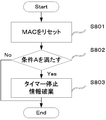
- UE122 performs the following processing.
- step S803 If the UE 122 satisfies the condition A (step S802), (A) stop if the timer T320 is running, (B) discard if it holds the cell reselection priority information provided by idleModeMobilityControlInfo. (Step S803).
- the condition A may include, for example, a case of leaving RRC_INACTIVE and a case of leaving RRC_INACTIVE (Leaving RRC_INACTIVE) not triggered by the RRC connection release.
- the condition A may include, for example, a case of leaving RRC_INACTIVE and a case of leaving RRC_INACTIVE (Leaving RRC_INACTIVE) not triggered by an RRC connection release message.
- condition A is, for example, the case where the user leaves the RRC_INACTIVE, and the case where the leaving RRC_INACTIVE (Leaving RRC_INACTIVE) is not triggered by the RRC connection release message received in response to the RRC connection return request message. May be included.
- condition A is, for example, when leaving RRC_INACTIVE, and (1) leaving RRC_INACTIVE is not triggered by RRC connection release, or (2) leaving RRC_INACTIVE is RRC connection release message. It may be included when it is triggered by and ignores idleModeMobilityControlInfo included in the RRC connection release message.
- condition A is, for example, when leaving RRC_INACTIVE, where (1) leaving RRC_INACTIVE was not triggered by RRC connection release, or (2) leaving RRC_INACTIVE was caused by RRC connection release. It may be included if it is triggered and is triggered by an RRC connection release message that does not include idleModeMobilityControlInfo.
- condition A is, for example, when leaving RRC_INACTIVE, and (1) leaving RRC_INACTIVE is not triggered by RRC connection release, or (2) leaving RRC_INACTIVE is RRC connection release message. It may be included when the UE 122 ignores the content of redirectedCarrierInfo included in the RRC connection release message or ignores the content of idleModeMobilityControlInfo included in the RRC connection release message.
- condition A is, for example, when leaving RRC_INACTIVE, and (1) leaving RRC_INACTIVE is not triggered by RRC connection release, or (2) leaving RRC_INACTIVE is RRC connection release message. May have been triggered by and the UE 122 did not retain the cell reselection priority information provided by the RRC connection release message.
- condition A may include a combination of the plurality of conditions described above.
- step S803 may not be executed. Also, for example, when leaving RRC_INACTIVE, if leaving RRC_INACTIVE is triggered by the RRC connection release and is triggered by the RRC connection release including idleModeMobilityControlInfo, it is included in step S803. The processing to be performed may not be executed.
- triggered by RRC connection release means (1) triggered by receiving an RRC connection release message and (2) regardless of whether an RRC connection release message is received or not. Either or both meanings triggered by being released may be included.
- timer T322 may be a timer used to control a period in which the information of a part of the offsets individually notified to the UE 122 is applied.
- timer T325 may be a timer used for controlling a certain carrier frequency (for example, the carrier frequency that has received the RRC connection refusal message) or a period in which the priority of the RAT is lowered (de-prioritized).
- T330 may be a timer used to control the measurements performed by the UE 122 in RRC_IDLE.
- step S805 If leaving the RRC_CONNECTED is triggered by the suspension of the RRC (step S805), the following processing 2A is performed (step S806), and if not, processing 2B is performed (step S807).
- Process 2A Re-establishing (also referred to as re-establishing) the RLC entities of all SRBs and DRBs including the radio bearer configured (configured with NR PDCP) together with NR PDCP.
- Current RRC setting current security context, PDCP state including ROHC state, C-RNTI used in PCell of connection source (Source), cell identifier (cellIdentity), physical cell identifier of PCell of connection source Alternatively, the UE AS Context including a part is retained. Holds all or part of the resumeIdentity, nextHopChainingCount, if present, and drb-ContinueROHC, provided by E-UTRAN.
- nextHopChainingCount may be information related to the parameter NCC and used for updating the key.
- drb-ContinueROHC may be information indicating whether to continue or reset the information (context) of the header compression protocol for DRB set by the header compression protocol.
- Process 2B Release all radio resources including release of RLC entity for all established radio bearers and PDCP entity associated with MAC configuration. It notifies the upper layer of the release of the RRC connection together with the release reason.
- PagingRecord may include information that identifies the target UE 122.
- Process 3A If ue-Identity included in PagingRecord matches one of the UE identifiers assigned by the upper layer, ue-Identity, accessType, etc. are transferred to the upper layer.
- accessType may be information indicating an access type, and may include, for example, circuit switched (CS) and packet switched (PS).
- Process 3B If the ue-Identity included in PagingRecord matches the I-RNTI held by the UE, the UE 122 sets the reason value (Cause Value) based on the set access identifier and performs the RRC connection return procedure. Start. Otherwise, if the ue-Identity contained in PagingRecord matches one of the UE identifiers assigned by the upper layer, transfer ue-Identity, accessType, etc. to the upper layer and set the release reason to "other". Set and execute the first operation.
- the reason value (Cause Value)
- Process 4A If the variable pendingRnaUpdate is set to TRUE, set it to FALSE. The release reason is set to "RRC recovery failure" and the first operation is executed.
- the UE 122 If the UE 122 sends the RRC connection return request message and does not receive the RRC connection return message, it resets the MAC and re-establishes RLC for all established radio bearers and suspends SRB1. Otherwise, reset the MAC to release the MAC settings and re-establish the RLC for all radio bearers established.
- UE 122 will stop if various timers including timer T320 are running.
- the value of some parameter included in the RRC connection return message. Ignore.
- RRC connection return message was received in response to the RRC connection return request for early data transmission (EDT)
- EDT early data transmission
- A If returning from a suspended RRC connection (returning from RRC_IDLE state), set the release reason to "other" and execute the first operation.
- B If returning from RRC_INACTIVE, specify the release reason.
- the first operation is executed by setting "RRC recovery failure", and the procedure ends.
- UE122 enters RRC_CONNECTED and notifies upper layers that the RRC connection has been restored.
- the UE 122 When entering RRC_INACTIVE, the UE 122 performs the following operations.
- the UE122 resets MAC and stops all timers except some timers.
- the part of the timer may include T320.
- UE 122 re-establishes RLC entities for all SRBs and DRBs.
- UE 122 applies the received settings (eg rrc-InactiveConfig).
- the UE 122 If the RRC connection release message is received in response to the RRC connection return request, the UE 122. All the security contexts it holds are replaced with the newly received security contexts (eg contained in rrc-InactiveConfig) and the C-RNTI it holds is the temporary C that the UE 122 was using when it received the RRC connection release message. -Replace with RNTI, and replace the held cell identifier (cellIdentity) and physical cell identifier (Physical cell identity) with the cellIdentity and physical cell identifier of the PCell when the UE 122 receives the RRC connection release message.
- the C-RNTI the temporary C that the UE 122 was using when it received the RRC connection release message.
- the UE AS context is retained.
- UE 122 starts a timer T380 used for RNA update, and suspends all SRBs and DRBs except SRB0.
- the RRC layer of the UE 122 notifies the upper layer of the suspension of the RRC connection, and enters RRC_INACTIVE.
- the UE 122 sets the release reason to “other” and performs the first operation. ..
- the operation (first operation) when leaving RRC_CONNECTED or RRC_INACTIVE may be executed in operations other than the above operations.
- FIG. 5 is a block diagram showing the configuration of the terminal device (UE 122) in the embodiment of the present invention. It should be noted that, in order to avoid complicating the description, FIG. 5 shows only the main components closely related to the present invention.
- the UE 122 illustrated in FIG. 5 receives the RRC connection reset message, the RRC connection return message, the RRC connection setup message, the RRC connection reject message, the RRC connection release message, and the like from the eNB 102, and various types included in the received message.
- the information processing apparatus includes an information element (IE: Information Element) and a processing unit 502 that performs processing in accordance with various conditions, and a transmission unit 504 that transmits an RRC connection restoration request message or the like to the eNB 102.
- a control unit that controls the operation of each unit based on various conditions may be separately provided.
- FIG. 6 is a block diagram showing the configuration of the base station device (eNB 102) in the embodiment of the present invention. It should be noted that, in order to avoid complication of the description, FIG. 6 shows only main components that are closely related to the present invention.
- the eNB 102 illustrated in FIG. 6 transmits a RRC connection reset message, an RRC connection return message, an RRC connection setup message, an RRC connection reject message, an RRC connection release message, and the like to the UE 122, and various information elements (IE: Information).
- the processing unit 602 is configured to cause the processing unit 502 of the UE 122 to perform processing by creating a message including Element), and the reception unit 604 that receives an RRC connection return request message and the like from the UE 122.
- the configuration shown in FIG. 6 may be applied to the gNB 108.
- the message transmitted from the transmission unit 600 to the UE 122 may be an RRC reconfiguration message, an RRC return message, an RRC setup message, an RRC reject message, an RRC release message, or the like.
- the eNB 102 and/or the gNB 108 may separately include a control unit that controls the operation of each unit based on various conditions.
- the UE 122 can realize appropriate mobility by holding or discarding the setting based on the state transition condition.
- the UE 122 can prevent unnecessary discarding of cell reselection priority information by discarding cell reselection priority information based on the condition in which the state transition is triggered.
- terminal device UE 122
- base station device eNB 102 and/or gNB 108
- a first aspect of the present invention is a terminal device, which transmits a first message requesting a return (resume) from an inactive state to a connected state, and a priority for cell selection.
- a reception unit that receives a second message that includes transition information (first information) and that instructs transition to an idle state (connection release); and a control unit that holds the first information, The control unit retains the first information when retaining the first information, based on at least whether the second message is received when transitioning from the inactive state to the idle state. Decide whether to do or discard.
- a second aspect of the present invention is a method applied to a terminal device, including a step of transmitting a first message requesting a return (resume) from an inactive state to a connected state, and cell selection.
- Receiving a second message instructing a transition to an idle state (release of a connection) the priority message including priority information (first information), and holding the first information.
- the control unit holds the first information based on whether or not at least the second message is received when transitioning from the inactive state to the idle state, the first information is stored. Determines whether to keep or destroy.
- a third aspect of the present invention is an integrated circuit mounted in a terminal device, which has a function of transmitting a first message requesting a return (resume) from an inactive state to a connected state, and a cell.
- the control unit retains the first information based on whether or not at least the second message is received when transitioning from the inactive state to the idle state. If so, it is determined whether to retain or discard the first information.
- a fourth aspect of the present invention is a terminal device, which transmits a first message requesting a return (resume) from an inactive state to a connected state, and a priority for cell selection. And a priority level information included in the second message, the reception unit receiving a second message including a priority information (first information) and instructing a transition to an idle state (connection release).
- a control unit wherein the control unit holds the first information when holding the first information based on at least whether the second message is received as a reply to the first message. Decide whether to keep or discard the information.
- a fifth aspect of the present invention is a terminal device, which transmits a first message requesting a return (resume) from an inactive state to a connected state, and a transition to an idle state ( A connection section) for receiving a second message instructing (release of connection), and a control section for holding priority information (first information) included in the second message. Based on whether or not the second message is received and the second message includes cell reselection priority information (first information) individually provided to the terminal device, When the first information is held, it is determined whether to hold or discard the priority information.
- the UE 122 can hold or discard the setting based on the condition of the state transition, and can realize appropriate mobility.
- the program that operates on the device related to the present invention may be a program that controls the Central Processing Unit (CPU) or the like to cause the computer to function so as to realize the functions of the above-described embodiments related to the present invention. ..
- the program or information handled by the program is temporarily read into a volatile memory such as Random Access Memory (RAM) at the time of processing, or stored in a nonvolatile memory such as a flash memory or a Hard Disk Drive (HDD), as necessary.
- RAM Random Access Memory
- HDD Hard Disk Drive
- the CPU reads, corrects, and writes.
- a part of the device in the above-described embodiment may be realized by a computer.
- the program for realizing this control function is recorded in a computer-readable recording medium, and the program recorded in this recording medium is read by the computer system and executed.
- the "computer system” referred to here is a computer system built in the apparatus, and includes operating systems and hardware such as peripheral devices.
- the "computer-readable recording medium” may be a semiconductor recording medium, an optical recording medium, a magnetic recording medium, or the like.
- a "computer-readable recording medium” means that a program can be held dynamically for a short period of time, such as a communication line for transmitting the program via a network such as the Internet or a communication line such as a telephone line. It may also include a program that holds a program for a certain period of time, such as a volatile memory inside a computer system that serves as a server or a client in that case. Further, the above-mentioned program may be for realizing a part of the above-mentioned functions, and may be one for realizing the above-mentioned functions in combination with a program already recorded in the computer system. ..
- each functional block or various features of the device used in the above-described embodiment may be implemented or executed by an electric circuit, that is, typically an integrated circuit or a plurality of integrated circuits.
- An electrical circuit designed to perform the functions described herein may be a general purpose processor, a digital signal processor (DSP), an application specific integrated circuit (ASIC), a field programmable gate array (FPGA), or others. Programmable logic devices, discrete gate or transistor logic, discrete hardware components, or combinations thereof.
- a general purpose processor may be a microprocessor, or in the alternative, the processor may be any conventional processor, controller, microcontroller, or state machine.
- the general-purpose processor, or each of the circuits described above may be configured by a digital circuit or an analog circuit. Further, in the case where an integrated circuit technology that replaces the current integrated circuit has appeared due to the progress of semiconductor technology, it is possible to use the integrated circuit according to the technology.
- the present invention is not limited to the above embodiment. Although an example of the apparatus is described in the embodiment, the present invention is not limited to this, and a stationary or non-movable electronic device installed indoors or outdoors, for example, an AV device, a kitchen device, It can be applied to terminal devices or communication devices such as cleaning/laundry equipment, air conditioning equipment, office equipment, vending machines, and other household appliances.
Landscapes
- Engineering & Computer Science (AREA)
- Computer Networks & Wireless Communication (AREA)
- Signal Processing (AREA)
- Computer Security & Cryptography (AREA)
- Mobile Radio Communication Systems (AREA)
Priority Applications (3)
| Application Number | Priority Date | Filing Date | Title |
|---|---|---|---|
| US17/428,657 US11950311B2 (en) | 2019-02-07 | 2020-02-06 | Terminal apparatus and method for storing priority information for cell reselection |
| CN202080012822.5A CN113396636B (zh) | 2019-02-07 | 2020-02-06 | 终端装置、方法以及集成电路 |
| EP20752303.6A EP3923673B1 (en) | 2019-02-07 | 2020-02-06 | Terminal apparatus, method, and integrated circuit for management of priority information for cell reselection |
Applications Claiming Priority (2)
| Application Number | Priority Date | Filing Date | Title |
|---|---|---|---|
| JP2019-020709 | 2019-02-07 | ||
| JP2019020709A JP6851406B2 (ja) | 2019-02-07 | 2019-02-07 | 端末装置、基地局装置、方法、および、集積回路 |
Publications (1)
| Publication Number | Publication Date |
|---|---|
| WO2020162528A1 true WO2020162528A1 (ja) | 2020-08-13 |
Family
ID=71947657
Family Applications (1)
| Application Number | Title | Priority Date | Filing Date |
|---|---|---|---|
| PCT/JP2020/004488 Ceased WO2020162528A1 (ja) | 2019-02-07 | 2020-02-06 | 端末装置、方法、および、集積回路 |
Country Status (5)
| Country | Link |
|---|---|
| US (1) | US11950311B2 (enExample) |
| EP (1) | EP3923673B1 (enExample) |
| JP (1) | JP6851406B2 (enExample) |
| CN (1) | CN113396636B (enExample) |
| WO (1) | WO2020162528A1 (enExample) |
Families Citing this family (4)
| Publication number | Priority date | Publication date | Assignee | Title |
|---|---|---|---|---|
| WO2020198272A1 (en) * | 2019-03-28 | 2020-10-01 | Kyocera Corporation | Resume failure report for failed attempt to resume connected state from inactive state |
| CN114760712A (zh) * | 2021-01-08 | 2022-07-15 | 大唐移动通信设备有限公司 | 数据发送处理方法、装置及处理器可读存储介质 |
| CN116437302B (zh) * | 2021-10-22 | 2024-07-05 | 华为技术有限公司 | 一种通信方法、装置和存储介质 |
| CN117119542A (zh) * | 2023-08-04 | 2023-11-24 | 华为技术有限公司 | 一种通信方法及通信装置 |
Citations (3)
| Publication number | Priority date | Publication date | Assignee | Title |
|---|---|---|---|---|
| WO2018128020A1 (ja) * | 2017-01-05 | 2018-07-12 | 日本電気株式会社 | 基地局及び無線端末並びにこれらの方法及び非一時的なコンピュータ可読媒体 |
| WO2018143415A1 (ja) * | 2017-02-03 | 2018-08-09 | 京セラ株式会社 | 無線端末、基地局、及び方法 |
| JP2019020709A (ja) | 2017-07-12 | 2019-02-07 | 太陽ホールディングス株式会社 | 感光性樹脂組成物、ドライフィルム、硬化物、半導体素子、プリント配線板および電子部品 |
Family Cites Families (10)
| Publication number | Priority date | Publication date | Assignee | Title |
|---|---|---|---|---|
| KR101119715B1 (ko) * | 2007-10-05 | 2012-03-23 | 엘지전자 주식회사 | 무선통신 시스템에서 셀 재선택 수행 방법 |
| US9173149B2 (en) * | 2010-10-21 | 2015-10-27 | Lg Electronics Inc. | Method for adjusting cell reselection priority for avoiding IDC interference in wireless communication system and device for same |
| KR101929307B1 (ko) * | 2011-04-11 | 2018-12-17 | 삼성전자 주식회사 | Csg 셀에서 단말이 셀 재선택 우선 순위를 효율적으로 제어하는 방법 및 장치 |
| US8837369B2 (en) * | 2011-07-05 | 2014-09-16 | Mediatek Inc. | System and method for indicating local IP access support via NAS signaling |
| CN103338500A (zh) * | 2012-12-24 | 2013-10-02 | 上海华为技术有限公司 | 一种数据传输方法、装置、系统及网络侧设备和终端设备 |
| US9736765B2 (en) * | 2014-04-28 | 2017-08-15 | Intel IP Corporation | Load balancing in a wireless cellular network based on user equipment mobility |
| US10813019B2 (en) * | 2015-05-13 | 2020-10-20 | Nokia Solutions And Networks Oy | Cell reselection control mechanism in multi-connectivity communication mode |
| WO2018084620A1 (ko) * | 2016-11-04 | 2018-05-11 | 엘지전자 주식회사 | 단말이 셀 재선택 절차를 수행하는 방법 및 이를 지원하는 장치 |
| US20190037635A1 (en) * | 2017-07-28 | 2019-01-31 | Asustek Computer Inc. | Method and apparatus of recovering rrc connection in a wireless communication system |
| WO2023175559A1 (en) * | 2022-03-16 | 2023-09-21 | Lenovo (Singapore) Pte. Ltd. | Configuring measurement and reporting based on a frequency |
-
2019
- 2019-02-07 JP JP2019020709A patent/JP6851406B2/ja active Active
-
2020
- 2020-02-06 CN CN202080012822.5A patent/CN113396636B/zh active Active
- 2020-02-06 WO PCT/JP2020/004488 patent/WO2020162528A1/ja not_active Ceased
- 2020-02-06 US US17/428,657 patent/US11950311B2/en active Active
- 2020-02-06 EP EP20752303.6A patent/EP3923673B1/en active Active
Patent Citations (3)
| Publication number | Priority date | Publication date | Assignee | Title |
|---|---|---|---|---|
| WO2018128020A1 (ja) * | 2017-01-05 | 2018-07-12 | 日本電気株式会社 | 基地局及び無線端末並びにこれらの方法及び非一時的なコンピュータ可読媒体 |
| WO2018143415A1 (ja) * | 2017-02-03 | 2018-08-09 | 京セラ株式会社 | 無線端末、基地局、及び方法 |
| JP2019020709A (ja) | 2017-07-12 | 2019-02-07 | 太陽ホールディングス株式会社 | 感光性樹脂組成物、ドライフィルム、硬化物、半導体素子、プリント配線板および電子部品 |
Non-Patent Citations (22)
Also Published As
| Publication number | Publication date |
|---|---|
| US20220132619A1 (en) | 2022-04-28 |
| EP3923673A1 (en) | 2021-12-15 |
| JP6851406B2 (ja) | 2021-03-31 |
| CN113396636B (zh) | 2024-01-23 |
| EP3923673A4 (en) | 2022-11-02 |
| EP3923673B1 (en) | 2025-04-02 |
| US11950311B2 (en) | 2024-04-02 |
| JP2020129719A (ja) | 2020-08-27 |
| CN113396636A (zh) | 2021-09-14 |
Similar Documents
| Publication | Publication Date | Title |
|---|---|---|
| US10129802B2 (en) | Layered connectivity in wireless systems | |
| WO2020162527A1 (ja) | 端末装置、基地局装置、方法、および、集積回路 | |
| WO2020162528A1 (ja) | 端末装置、方法、および、集積回路 | |
| JP7608044B2 (ja) | 端末装置、基地局装置、方法、および、集積回路 | |
| WO2021025150A1 (ja) | 端末装置、方法、および、集積回路 | |
| WO2019216392A1 (ja) | UE(User Equipment) | |
| WO2021149612A1 (ja) | 端末装置、基地局装置、および、方法 | |
| WO2020091047A1 (ja) | 端末装置、基地局装置、および方法 | |
| JP7777081B2 (ja) | 端末装置、基地局装置、および、方法 | |
| JP7739265B2 (ja) | 端末装置、方法、および、集積回路 | |
| WO2022080306A1 (ja) | 端末装置、基地局装置、および、方法 | |
| JP2020137084A (ja) | 端末装置、基地局装置、方法、および、集積回路 | |
| WO2020095851A1 (ja) | 端末装置、基地局装置、通信方法、および、集積回路 | |
| JP6807410B2 (ja) | 端末装置、基地局装置、および、通信方法 | |
| US20220167238A1 (en) | Terminal device, base station device, and communication method | |
| WO2023106315A1 (ja) | 端末装置、基地局装置、および、方法 | |
| WO2020195529A1 (ja) | 端末装置、基地局装置、および、方法 | |
| WO2023008043A1 (ja) | 端末装置、方法、および、集積回路 | |
| WO2025192703A1 (ja) | 端末装置、方法、および、集積回路 | |
| WO2023112179A1 (ja) | 第1無線通信装置、第2無線通信装置、通信方法及び通信プログラム | |
| WO2020166310A1 (ja) | 端末装置、および、方法 | |
| WO2023067646A1 (ja) | 第2無線通信装置及び第1無線通信装置 | |
| WO2022080341A1 (ja) | 端末装置、基地局装置、および、方法 |
Legal Events
| Date | Code | Title | Description |
|---|---|---|---|
| 121 | Ep: the epo has been informed by wipo that ep was designated in this application |
Ref document number: 20752303 Country of ref document: EP Kind code of ref document: A1 |
|
| NENP | Non-entry into the national phase |
Ref country code: DE |
|
| ENP | Entry into the national phase |
Ref document number: 2020752303 Country of ref document: EP Effective date: 20210907 |
|
| WWG | Wipo information: grant in national office |
Ref document number: 2020752303 Country of ref document: EP |