EP3923673B1 - Terminal apparatus, method, and integrated circuit for management of priority information for cell reselection - Google Patents
Terminal apparatus, method, and integrated circuit for management of priority information for cell reselection Download PDFInfo
- Publication number
- EP3923673B1 EP3923673B1 EP20752303.6A EP20752303A EP3923673B1 EP 3923673 B1 EP3923673 B1 EP 3923673B1 EP 20752303 A EP20752303 A EP 20752303A EP 3923673 B1 EP3923673 B1 EP 3923673B1
- Authority
- EP
- European Patent Office
- Prior art keywords
- rrc
- case
- rrc connection
- message
- priority information
- Prior art date
- Legal status (The legal status is an assumption and is not a legal conclusion. Google has not performed a legal analysis and makes no representation as to the accuracy of the status listed.)
- Active
Links
Images

Classifications
-
- H—ELECTRICITY
- H04—ELECTRIC COMMUNICATION TECHNIQUE
- H04W—WIRELESS COMMUNICATION NETWORKS
- H04W48/00—Access restriction; Network selection; Access point selection
- H04W48/16—Discovering, processing access restriction or access information
-
- H—ELECTRICITY
- H04—ELECTRIC COMMUNICATION TECHNIQUE
- H04W—WIRELESS COMMUNICATION NETWORKS
- H04W76/00—Connection management
- H04W76/20—Manipulation of established connections
-
- H—ELECTRICITY
- H04—ELECTRIC COMMUNICATION TECHNIQUE
- H04W—WIRELESS COMMUNICATION NETWORKS
- H04W48/00—Access restriction; Network selection; Access point selection
- H04W48/20—Selecting an access point
-
- H—ELECTRICITY
- H04—ELECTRIC COMMUNICATION TECHNIQUE
- H04W—WIRELESS COMMUNICATION NETWORKS
- H04W76/00—Connection management
- H04W76/20—Manipulation of established connections
- H04W76/27—Transitions between radio resource control [RRC] states
-
- H—ELECTRICITY
- H04—ELECTRIC COMMUNICATION TECHNIQUE
- H04W—WIRELESS COMMUNICATION NETWORKS
- H04W76/00—Connection management
- H04W76/30—Connection release
-
- H—ELECTRICITY
- H04—ELECTRIC COMMUNICATION TECHNIQUE
- H04W—WIRELESS COMMUNICATION NETWORKS
- H04W88/00—Devices specially adapted for wireless communication networks, e.g. terminals, base stations or access point devices
- H04W88/02—Terminal devices
Definitions
- the present invention relates to a terminal apparatus, a method, and an integrated circuit for management of priority information for cell reselection.
- a radio access method and a radio network for cellular mobile communications (which will hereinafter be referred to as “Long Term Evolution (LTE; trade name)” or “Evolved Universal Terrestrial Radio Access (E-UTRA)") and a core network (which will be referred to as “Evolved Packet Core or EPC”) have been studied by the 3rd Generation Partnership Project (3GPP).
- LTE Long Term Evolution
- E-UTRA Evolved Universal Terrestrial Radio Access
- EPC Evolved Packet Core
- One aspect of the present invention is realized with the situations described above taken into account, and one object thereof is to provide a terminal apparatus capable of efficiently performing cell selection and/or re-selection of the terminal apparatus, a method used for the terminal apparatus, and an integrated circuit mounted in the terminal apparatus.
- the terminal apparatus can efficiently perform cell selection and/or re-selection based on an optimum parameter configuration.
- LTE (and LTE-A Pro) and NR may be defined as different RATs.
- the NR may be defined as a technology included in the LTE.
- the LTE may be defined as a technology included in the NR.
- the LTE that is connectable to the NR using Multi RAT Dual connectivity may be distinguished from the existing LTE.
- LTE with a core network of 5GC may be distinguished from the existing LTE with a core network of EPC.
- the present embodiment may be applied to the NR, the LTE and other RATs. Terms associated with the LTE and the NR are used in the following description. However, the present invention may be applied to other technologies using other terms.
- the term "E-UTRA" may be replaced with "LTE”
- the term "LTE" may be replaced with "E-UTRA”.
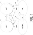
- FIG. 1 is a schematic diagram of a communication system according to each embodiment of the present invention.
- An E-UTRA 100 is a radio access technology described in NPL 3 or the like, and includes a cell group (CG) configured in one or multiple frequency bands.
- An E-UTRAN Node B (eNB) 102 is a base station apparatus of the E-UTRA 100.
- An Evolved Packet Core (EPC) 104 is a core network described in NPL 14 or the like and is designed as a core network for the E-UTRA 100.
- An interface 112 is an interface between the eNB 102 and the EPC 104, where there is a control plane (CP) through which control signals are transferred and a user plane (UP) through which user data is transferred.
- CP control plane
- UP user plane
- An interface 114 is an interface between the eNB 102 and the 5GC 110
- an interface 116 is an interface between the gNB 108 and the 5GC 110
- an interface 118 is an interface between the gNB 108 and the EPC 104
- an interface 120 is an interface between the eNB 102 and the gNB 108
- an interface 124 is an interface between the EPC 104 and the 5GC 110.
- the interface 114, the interface 116, the interface 118, the interface 120, the interface 124, and the like may be interfaces that transfer CP only, UP only, or both the CP and the UP.
- the interface 114, the interface 116, the interface 118, the interface 120, the interface 124, and the like may not exist depending on communication systems provided by network operators in some cases.
- a UE 122 is a terminal apparatus supporting the NR 106 or both the E-UTRA 100 and the NR 106.
- a Radio Bearer (RB) is established between the UE 122 and the E-UTRA 100 and/or the NR 106.
- the radio bearer used for the CP is referred to as a Signaling Radio Bearer (SRB)
- SRB Signaling Radio Bearer
- DRB Data Radio Bearer
- An RB Identity (or RB ID) is assigned to each RB and the RB is uniquely identified.
- the RB identity for SRB is referred to as an SRB Identity (or SRB ID)
- the RB identity for DRB is referred to as a DRB Identity (or DRB ID).
- each DRB established between the UE 122 and the E-UTRA 100 and/or the NR 106 is further uniquely linked to each Evolved Packet System (EPS) bearer passing through the inside the EPC 104.
- EPS bearer Identity (or ID) is assigned to each EPS bearer and the bearer is uniquely identified. Furthermore, for data passing through the same EPS bearer, the same QoS is ensured.
- one or multiple DRBs established between the UE 122 and the E-UTRA 100 and/or the NR 106 are further linked to one of Packet Data Unit (PDU) sessions established in the 5GC 110.
- PDU Packet Data Unit
- One or multiple QoS flows are present in each PDU session.
- Each DRB may be mapped with one or multiple QoS flows present in the PDU session to which the DRB is linked, or may not be mapped to any QoS flows.
- Each PDU session is identified by a PDU session Identity (or ID).
- each QoS flow is identified by a QoS flow identity. Furthermore, for data passing through the same QoS flow, the same QoS is ensured.
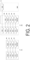
- FIG. 2 is a diagram of protocol stacks of UP and CP of a terminal apparatus and a base station apparatus in an E-UTRA radio access layer according to each embodiment of the present invention.
- FIG. 2(A) is a diagram of the protocol stack of the UP used in a case that the UE 122 communicates with the eNB 102 in the E-UTRA 100.
- a physical layer (PHY) 200 is a radio physical layer for providing a transmission service to an upper layer by using a physical channel.
- the PHY 200 is connected with a Medium Access Control layer (MAC) 202 of an upper layer to be described below via transport channels. Data is exchanged between the MAC 202 and the PHY 200 via the transport channels. The data is transmitted and/or received via radio physical channels between the PHYs of the UE 122 and the eNB 102.
- MAC Medium Access Control layer
- the MAC 202 is a medium access control layer that maps various logical channels to various transport channels.
- the MAC 202 is connected with a radio link control layer (RLC) 204 of an upper layer to be described below via logical channels.
- RLC radio link control layer
- the major classifications of the logical channel depend on the type of information to be transmitted, specifically, the logical channels are classified into control channels for transmitting control information and traffic channels for transmitting user information.
- the MAC 202 has a function of controlling the PHY 200 in order to perform the Discontinuous Reception and Transmission (DRX and DTX), a function of performing a random access procedure, a function of reporting transmit power information, a function of performing HARQ control, and the like (NPL 7).
- the RLC 204 is a radio link control layer that divides (Segmentation) the data received from a Packet Data Convergence Protocol Layer (PDCP) 206 of an upper layer to be described below, and adjusts the data size such that a lower layer can properly perform data transmission. Furthermore, the RLC 200 also has a function of ensuring Quality of Service (QoS) required for each piece of data. In other words, the RLC 204 has a function of data retransmission control or the like (NPL 6).
- QoS Quality of Service
- the PDCP 206 is a packet data convergence protocol layer for efficiently transmitting an IP Packet, which is user data, in a radio section.
- the PDCP 206 may have a header compression function of compressing unnecessary control information.
- the PDCP 206 may also have a data encryption function (NPL 5).
- MAC Protocol Data Unit PDU
- RLC PDU RLC Physical Downlink Control Protocol Data Unit
- PDCP PDU PDCP Physical Downlink Control Protocol Data Unit
- SDU MAC Service Data Unit
- FIG. 2(B) is a diagram of the protocol stack of the CP used in a case that the UE 122 communicates with the eNB 102 and a Mobility Management Entity (MME), which is a logical node for providing functions such as authentication and mobility management, in the E-UTRA 100.
- MME Mobility Management Entity
- the RRC 208 is a radio link control layer that performs processing such as establishment, re-establishment, suspending, and resuming of suspending of RRC connection, a reconfiguration of RRC connection, for example, configurations of establishment, change, release, and the like of a Radio Bearer (RB) and a Cell Group, and performs, in addition to performing control and the like of a logical channel, a transport channel, and a physical channel, configurations and the like of a handover and Measurement.
- RB Radio Bearer
- the RBs may be classified into a Signaling Radio Bearer (SRB) and a Data Radio Bearer (DRB), and the SRB may be used as a path for transmitting an RRC message which is control information.
- the DRB may be used as a path for transmitting the user data.
- Each RB may be configured between the RRCs 208 of the eNB 102 and the UE 122.
- a portion of the RB including the RLC 204 and the MAC 202 may be referred to as an RLC bearer (NPL 4).
- AS Access Strarum
- the functional classification of the MAC 202, the RLC 204, the PDCP 206, and the RRC 208 described above is an example, and some or all of the respective functions may not be implemented. Some or all of the functions of each layer may be included in another layer.
- an IP layer and a Transmission Control Protocol (TCP) layer, a User Datagram Protocol (UDP) layer, an application layer, and the like that are upper layers than the IP layer are upper layers than the PDCP layer (not illustrated).
- the RRC layer and a non Access Strarum (NAS) layer are also upper layers of the SDAP layer (not illustrated).
- the PDCP layer is a lower layer of the RRC layer, the NAS layer, the IP layer, and the Transmission Control Protocol (TCP) layer, the User Datagram Protocol (UDP) layer, and the application layer that are upper layers than the IP layer.
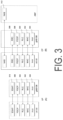
- FIG. 3 is a diagram of protocol stacks of UP and CP of a terminal apparatus and a base station apparatus in an NR radio access layer according to each embodiment of the present invention.
- FIG. 3(A) is a diagram of the protocol stack of the UP used in a case that the UE 122 communicates with the gNB 108 in the NR 106.
- a physical layer (PHY) 300 is a radio physical layer of the NR and may provide a transmission service to an upper layer by using the physical channel.
- the PHY 300 may be connected with the Medium Access Control layer (MAC) 302 of an upper layer to be described below via the transport channels. Data may be exchanged between the MAC 302 and the PHY 300 via the transport channels. The data may be transmitted and/or received between the PHYs of the UE 122 and the gNB 108 via the radio physical channel.
- MAC Medium Access Control layer
- the MAC 302 is a medium access control layer that maps various logical channels to various transport channels.
- the MAC 302 may be connected with a Radio Link Control layer (RLC) 304 of an upper layer to be described below via the logical channels.
- RLC Radio Link Control layer
- the classification of the logical channel depends on the type of information to be transmitted, and the logical channels may be classified into the control channels for transmitting the control information and the traffic channels for transmitting the user information.
- the MAC 302 has a function of controlling the PHY 300 in order to perform the Discontinuous Reception and Transmission (DRX and DTX), a function of performing the random access procedure, a function of reporting the transmit power information, a function of performing the HARQ control, and the like (NPL 13).
- the RLC 304 is a radio link control layer that divides (Segmentation) the data received from the Packet Data Convergence Protocol Layer (PDCP) 206 of an upper layer to be described below, and adjusts the data size such that a lower layer can properly perform data transmission. Furthermore, the RLC 304 may also have a function of ensuring Quality of Service (QoS) required for each piece of data. In other words, the RLC 304 may have a function of data retransmission control or the like (NPL 12).
- QoS Quality of Service
- a PDCP 306 is a packet data convergence protocol layer that efficiently transmits an IP Packet, which is user data, in a radio section.
- the PDCP 306 may have a header compression function of compressing unnecessary control information.
- the PDCP 306 may also have a data encryption function (NPL 11).
- a Service Data Adaptation Protocol (SDAP) 310 is a service data adaptation protocol layer that has a function of mapping a QoS flow of a downlink transmitted from the 5GC 110 to a terminal apparatus through a base station apparatus and a DRB, mapping a QoS flow of an uplink transmitted from the terminal apparatus to the 5GC 110 through the base station apparatus and the DRB, and storing mapping rule information (NPL 16).
- SDAP Service Data Adaptation Protocol
- FIG. 3(B) is a diagram of the protocol stack of the CP used in a case that the UE 122 communicates with the gNB 108 and an Access and Mobility Management function (AMF), which is a logical node for providing functions such as authentication and mobility management, in the NR 106.
- AMF Access and Mobility Management function
- the RRC 308 is a radio link control layer that performs processing such as establishment, re-establishment, suspending, and resuming of suspending of RRC connection, a reconfiguration of RRC connection, for example, configurations of establishment, change, release, and the like of a Radio Bearer (RB) and a Cell Group, and performs, in addition to performing control and the like of a logical channel, a transport channel, and a physical channel, configurations and the like of handover and Measurement.
- RB Radio Bearer
- AS Access Strarum
- the functional classification of the MAC 302, the RLC 304, the PDCP 306, the SDAP 310, and the RRC 308 described above is an example, and some or all of the functions may not be implemented. Furthermore, some or all of the functions of each layer may be included in another layer.
- each layer configured to the terminal apparatus and/or the base station apparatus may be referred to as an entity. That is, the MAC layer, the RLC layer, the PDCP layer, the SDAP layer, and the RRC layer configured to the terminal apparatus and/or the base station apparatus may be referred to as an MAC entity, an RLC entity, a PDCP entity, an SDAP entity, and an RRC entity, respectively.
- the MAC 202, the RLC 204, the PDCP 206, and the RRC 208 may be respectively referred to as a MAC for E-UTRA or a MAC for LTE, an RLC for E-UTRA or an RLC for LTE, a PDCP for E-UTRA or a PDCP for LTE, and an RRC for E-UTRA or an RRC for LTE.
- the MAC 302, the RLC 304, the PDCP 306, and the RRC 308 may also be referred to as MAC for NR, RLC for NR, RLC for NR, and RRC for NR, respectively.
- MAC for NR RLC for NR
- RLC for NR RLC for NR
- RRC for NR RRC for NR
- the eNB 102, the gNB 108, the EPC 104, and the 5GC 110 may be connected to one another via the interface 112, the interface 116, the interface 118, the interface 120, and the interface 114.
- the RRC 208 in FIG. 2 may be replaced with the RRC 308 in FIG. 3 to support various communication systems.
- the PDCP 206 in FIG. 2 may also be replaced with the PDCP 306 in FIG. 3 .
- the RRC 308 in FIG. 3 may include the function of the RRC 208 in FIG. 2 .
- the PDCP 306 in FIG. 3 may be the PDCP 206 in FIG. 2 .
- the NR PDCP may be used as a PDCP.
- the UE 122 may be in an RRC_CONNECTED state in a case that an RRC connection has been established. Additionally, in a case that the RRC connection is suspended, (in a case that the UE 122 is connected to the 5GC), the UE 122 may be in an RRC_INACTIVE state. In a case that these cases are not established, the UE 122 may be in the RRC_IDLE state.
- the UE 122 connected to the EPC does not have the RRC_INACTIVE state, but suspension of the RRC connection may be started by the E-UTRAN.
- the UE 122 in a case that the RRC connection is suspended, stores an AS context of the UE and an identity (resumeIdentity) used for the resume, and transitions to the RRC_IDLE state.
- the resume of the RRC connection is permitted by the E-UTRAN, and the UE 122 is required to transition from the RRC_IDLE state to the RRC_CONNECTED state, the resume of the suspended RRC connection may be started by the upper layer (e.g., the NAS layer).
- the definition of suspension may differ between the UE 122 connected to the EPC and the UE 122 connected to the 5GC. Furthermore, between a case that the UE 122 is connected to the EPC (a case of suspending in the RRC_IDLE state) and a case that the UE is connected to the 5GC (a case of suspending in the RRC_INACTIVE state), all or part of a procedure of resuming from the suspension may be different.
- the AS context of the UE stored by the UE 122 may be information that includes all or some of a current RRC configuration, a current security context, a PDCP state including a RObust Header Compression (ROHC) state, a C-RNTI used in a connection source PCell, a cell identity (cellIdentity), and a physical cell identity of the connection source PCell.
- the AS context of the UE stored by the eNB 102 and/or the gNB 108 may include the same information as the AS context of the UE stored by the UE 122, or may include information different from the information included in the AS context of the UE stored by the UE 122.
- the security context may be information that includes all or part of a cipher key at the AS level, a Next Hop parameter (NH), a Next Hop Chaining Counter parameter (NCC) used for access key derivation of the next hop, an identity of an encryption algorithm of the selected AS level, a counter used for replay protection.
- NH Next Hop parameter
- NCC Next Hop Chaining Counter parameter
- RRC radio resource control
- This procedure may be used to transfer the UE 122 from RRC_INACTIVE to RRC_CONNECTED. This procedure may be initiated in a case that there is a request for resume of the RRC connection from the upper layer of the RRC, or in a case that the RRC requests the resume of the RRC connection (e.g., for notifying the network that the RNA is changed due to cell re-selection (RNA update), or due to reception of paging of the RAN by the UE 122 in RRC_INACTIVE).
- RNA update cell re-selection
- the UE 122 stops a timer T380 used to trigger processing of the RNA update, and starts transmission processing of an RRC connection resume request (RRCConnectionResumeRequest) message described below.
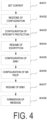
- the UE 122 performs setting as described below, as a content to be included in the RRC connection resume request message (step S401).
- system information to be broadcast includes information indicating that full ResumeID is used
- the value of a full I-RNTI (fullI-RNTI) that is provided at Suspending and Stored is set to fullI-RNTI.
- the value of a short I-RNTI (shortI-RNTI) that is provided at suspending and stored is set to shortI-RNTI.
- the full I-RNTI is an identity used to identify the suspended UE context of the UE 122 in RRC_INACTIVE, and may be information of 40 bits, for example.
- the short I-RNTI is also an identity used to identify the suspended UE context of the UE 122 in RRC _INACTIVE, but a smaller number of bits than that of the full I-RNTI is used therefor.
- the short I-RNTI may be information of 24 bits.
- the UE context here is information related to the UE 122 stored by the network, and may include information of capability related to security and information of capability related to the radio of the UE 122.
- resumeCause is information indicating a cause for the resume to be included in the RRC connection resume request message.
- resumeCause includes emergency indicating being an emergency call, rna-Update indicating being resume for update of the RNA, and the like.
- shortResumeMAC-I is information used as an authentication token to facilitate authentication of the UE 122 at the eNB 102 and/or the gNB 108.
- step S402 except for the configuration of the PHY and the MAC, the RRC configuration and the security context are restored from the stored AS context of the UE (step S402).
- a key used for Integrity protection is updated, and the lower layer is configured such that the integrity protection is resumed for all SRBs other than SRB0 (step S403).
- the lower layer is configured such that encryption is resumed for all radio bearers other than the SRB0 (step S404).
- a default configuration is applied to SRB 1 (step S405).
- a default NR PDCP configuration is applied (step S406).
- the UE 122 submits the RRC connection resume request message to the lower layer for transmission (step S408).
- an RRC connection resume message, an RRC connection setup message, an RRC connection rejection message, an RRC connection release message, and the like may be transmitted from the eNB 102 or the gNB 108 to the UE 122.
- the eNB 102 or the gNB 108 may transmit the RRC connection resume message to the UE 122 in order to resume the connected state of the UE 122. Furthermore, the eNB 102 or the gNB 108 may transmit the RRC connection setup message to the UE 122 in order to cause the UE 122 to establish the connected state instead of resume. Furthermore, the eNB 102 or the gNB 108 may transmit the RRC connection rejection message to the UE 122 in order to return the UE 122 to the inactive state. Furthermore, the eNB 102 or the gNB 108 may transmit the RRC connection release message to the UE 122 in order to shift the UE 122 to the idle state.
- redirectedCarrierInfo may be information indicating, for example, a carrier frequency (of downlink in the FDD) and a type of a target RAT (e.g., EUTRA, GERAN, UTRA-FDD, UTRA-TDD, NR release 15, and the like).
- freqPriorityListGERAN may be information indicating, for example, information of cell re-selection priority of each frequency in the GERAN.
- idleModeMobilityControlInfo may be information, for example, for providing information of cell re-selection priority individually for the UE 122 and may be used for cell re-selection of the UE 122.
- Processing 1A In a case that AS security is not activated and in a case that the upper layer indicates not permitting redirection to the GERAN without the AS security or the UE 122 is connected to the 5GC, the content of the RRC connection release message is ignored, the release cause is configured to "other", an operation (first operation) in a case of leaving RRC_CONNECTED or RRC_INACTIVE described later is performed, and this procedure is terminated (step S703).
- step S704 In a case that the AS security is not activated, processing 1B as described below is performed, and otherwise the process transitions to step S706 without performing the processing 1B (step S704).
- Processing 1B In a case that redirection to the NR is indicated, the content of redirectedCarrierInfo is ignored. In a case that freqPriorityListNR is included in idleModeMobilityControlInfo, the content of idleModeMobilityControlInfo is ignored. In a case that the UE 122 ignores the content of redirectedCarrierInfo or idleModeMobilityControlInfo, the release cause is configured to "other", the first operation described later is performed, and this procedure is terminated (step S705).
- freqPriorityListNR may be information indicating, for example, information of the cell re-selection priority of each frequency in the NR.
- step S706 In a case that the RRC connection release message includes redirectedCarrierInfo indicating redirection to the EUTRA and the UE 122 is connected to the 5GC, processing 1C described below is performed, and otherwise the process transitions to step S708 without performing the processing 1C (step S706).
- Processing 1C In a case that the RRC connection release message includes cn-Type, this received cn-Type is provided to the upper layer (step S707).
- processing 1D described below is performed, and otherwise processing 1E is performed (step S708).
- a timer T320 is started with a timer value set in accordance with the value of this t320 (step S709).
- the timer T320 may be a timer used to manage a period during which the cell re-selection priority information of which the UE 122 is individually notified is applied, and may be started at the time of receiving t320.
- the timer T320 may be started under another condition.
- the timer T320 may be stopped at the time of entering RRC_CONNECTED. Furthermore, the timer T320 may be stopped under another condition.
- the cell re-selection priority information of which the UE 122 is individually notified may be discarded.
- Processing 1E The cell re-selection priority information broadcast with system information is applied (step S710).
- the release cause included in the RRC connection release message indicates loadBalancingTAURequired (step S711)
- the release cause is configured to "load Balancing TAU Required", and the first operation described later is performed (step S712).
- loadBalancingTAURequired may be information indicating that a load distribution of TAU is required, for example.
- cs-FallbackHighPriority may be information indicating being Circuit Switched FallBack having a high priority, for example.
- Processing 1F In a case that there is extendedWaitTime and in a case that the UE 122 supports delay allowable access or the UE 122 is an Nb-IoT UE, extendedWaitTime is transferred to the upper layer (step S716). In a case that the release cause included in the RRC connection release message indicates rrc-Suspend, processing 1G described below is performed, and otherwise processing 1H is performed (step S717).
- rrc-Suspend may be information indicating that the RRC connection is suspended.
- rrc-InactiveConfig In a case that rrc-InactiveConfig is included, processing for entering RRC_INACTIVE is performed, otherwise the release cause is configured to "RRC suspension", and the first operation described later is performed (step S718).
- rrc-InactiveConfig may be a configuration that the UE 122 entering RRC_INACTIVE applies, for example.
- Processing 1H The release cause is configured to "other", and the first operation described later is performed (step S719).
- the UE 122 performs the following processing.
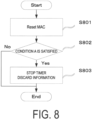
- the MAC is reset (step S801).
- step S802 In a case that the UE 122 satisfies a condition A (step S802), (A) in a case the timer T320 is running, the timer is stopped, and (B) in a case that the cell re-selection priority information provided by idleModeMobilityControlInfo is stored, the information is discarded (step S803).
- condition A described above includes, according to the claimed invention, a case of leaving RRC_INACTIVE and transitioning to RRC_IDLE, and leaving RRC _INACTIVE and transitioning to RRC_IDLE is not triggered by the RRC connection release message.
- the following examples for the condition A are not or not completely encompassed by the wording of the claims, but are considered as useful for understanding the invention.
- the condition A described above may include, for example, a case of leaving RRC_INACTIVE, and a case that leaving RRC_INACTIVE is not triggered by the RRC connection release message.
- condition A described above may include, for example, a case of leaving RRC_INACTIVE, and a case that leaving RRC_INACTIVE is not triggered by the RRC connection release message received as a reply to the RRC connection resume request message.
- condition A described above may include, for example, a case of leaving RRC_INACTIVE, and a case that (1) leaving RRC_INACTIVE is not triggered by the RRC connection release, or (2) leaving RRC_INACTIVE is triggered by the RRC connection release message and idleModeMobilityControlInfo included in the RRC connection release message is ignored.
- condition A described above may include, for example, a case of leaving RRC_INACTIVE, and a case that (1) leaving RRC_INACTIVE is not triggered by the RRC connection release, or (2) leaving RRC_INACTIVE is triggered by the RRC connection release and is triggered by the RRC connection release message not including idleModeMobilityControlInfo.
- condition A described above may include, for example, a case of leaving RRC_INACTIVE, and a case that (1) leaving RRC_INACTIVE is not triggered by the RRC connection release, or (2) leaving RRC_INACTIVE is triggered by the RRC connection release message, and the UE 122 ignores the content of redirectedCarrierInfo included in the RRC connection release message, or ignores the content of idleModeMobilityControlInfo included in the RRC connection release message.
- condition A described above may include, for example, a case of leaving RRC_INACTIVE, and a case that (1) leaving RRC_INACTIVE is not triggered by the RRC connection release, or (2) leaving RRC_INACTIVE is triggered by the RRC connection release message and the UE 122 does not store the cell re-selection priority information provided by the RRC connection release message.
- condition A described above may include a combination of the multiple conditions described above.
- the U 122 may not perform processing included in step S803.
- step S803 may not be performed.
- processing included in step S803 may not be performed.
- the expression "triggered by the RRC connection release” may include the meaning of either or both (1) triggered by receiving the RRC connection release message and (2) triggered by the RRC connection being released regardless of whether or not the RRC connection release message has been received.
- Timer other than timers T320, T322, T325, and T330 is stopped (step S804).
- the timer T322 may be a timer used to control a period during which part of offset information of which the UE 122 is individually notified is applied.
- the timer T325 may be a timer used to control a period of a carrier frequency (e.g., a carrier frequency with which an RRC connection refusal message is received) or during which the priority of the RAT is lowered (de-prioritised).
- the timer T330 may be a timer used to control measurement performed by the UE 122 in the RRC_IDLE.
- step S805 In a case that leaving RRC_CONNECTED is triggered by suspension of the RRC (step S805), the following processing 2A is performed (step S806), and otherwise processing 2B is performed (step S807).
- RLC entities of all SRBs and DRBs including a radio bearer configured with the NR PDCP are re-established (also referred to as re-founded).
- a UE AS Context is stored which includes all or some of a current RRC configuration, a current security context, a PDCP state including an ROHC state, a C-RNTI used in a connection source PCell, a cell identity (cellIdentity), and a physical cell identity of the connection source PCell. All or some of resumeIdentity, nextHopChainingCount in a case of being present, and drb-ContinueROHC in a case of being present, provided by E-UTRAN are stored.
- nextHopChainingCount may be information associated with the parameter NCC and used to update the key.
- drb-ContinueROHC may be information indicating whether to continue using or reset information (context) of the header compression protocol for the DRB configured in the header compression protocol.
- PagingRecord may include information for identifying the UE 122 to be a target.
- Processing 3A In a case that ue-Identity included in PagingRecord matches one of UE identities assigned by the upper layer, ue-Identity, accessType, and the like are transferred to the upper layer.
- accessType may be information indicating an access type, and for example, may include circuit switched (CS), packet switched (PS), and the like.
- Processing 3B In a case that ue-Identity included in PagingRecord matches the stored I-RNTI, a Cause Value based on an access identity with which the UE 122 is configured is configured, and the RRC connection resume procedure is initiated. Otherwise, in a case that ue-Identity included in PagingRecord matches one of UE identities assigned by the upper layer, ue-Identity, accessType, and the like are transferred to the upper layer, the release cause is configured to "other", and the first operation is performed.
- processing 4A described below is performed.
- Processing 4A In a case that a variable pendingRnaUpdate is set to TRUE, the variable is set to FALSE.
- the release cause is configured to "RRC resume failure", and the first operation is performed.
- the MAC is reset, the RLC for all established radio bearers is re-established, and the SRB1 is suspended. Otherwise, the MAC is reset, the configuration of the MAC is released, and the RLC for all established radio bearers is re-established.
- the release cause is configured to "RRC connection failure", and the first operation is performed.
- the UE 122 stops various timers including the timer T320, in a case that the timers are running.
- the RRC connection resume message is received as a reply to the RRC connection resume request for Early Data Transmission (EDT)
- EDT Early Data Transmission
- a value of part of parameters (e.g., nextHopChyainingCounter) included in the RRC connection resume message is ignored.
- the RRC connection resume message is not a message received as a reply to the RRC connection resume request for the Early Data Transmission (EDT)
- EDT Early Data Transmission
- the release cause is configured to "other" and the first operation is performed
- the release cause is configured to "RRC resume failure"
- the first operation is performed, and this procedure is terminated.
- the UE 122 enters RRC_CONNECTED and notifies the upper layer that the RRC connection is resumed.
- the UE 122 performs the following operations.
- the UE 122 resets the MAC and stops all timers except some timers.
- Some timers described above may include T320.
- the UE 122 re-establishes RLC entities for all SRBs and DRBs.
- the UE 122 applies the received configuration (e.g., rrc-InactiveConfig).
- the received configuration e.g., rrc-InactiveConfig.
- the UE 122 In a case of receiving the RRC connection release message as a reply to the RRC connection resume request, the UE 122 replaces stored security contexts with newly received security contexts (e.g., included in rrc-InactiveConfig), replaces the stored C-RNTI with a temporary C-RNTI used in a case that the UE 122 receives the RRC connection release message, and replaces the stored cell identity (cellIdentity) and Physical cell identity with cellIdentity and the physical cell identity of the PCell in a case that the UE 122 receives the RRC connection release message.
- stored security contexts e.g., included in rrc-InactiveConfig
- the AS context of the UE is stored.
- the UE 122 starts the timer T380 used for update of the RNA and suspends all SRBs and DRBs except SRB0.
- the RRC layer of the UE 122 notifies the upper layer of suspension of the RRC connection and enters RRC _INACTIVE.
- the UE 122 configures the release cause to "other", and performs the first operation.
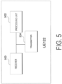
- FIG. 5 is a block diagram illustrating a configuration of the terminal apparatus (UE 122) according to an embodiment of the present invention. Note that FIG. 5 illustrates only the main components closely related to the present invention in order to avoid complexity of description.
- the UE 122 illustrated in FIG. 5 includes a receiver 500 configured to receive, from the eNB 102, an RRC connection reconfiguration message, an RRC connection resume message, an RRC connection setup message, an RRC connection rejection message, an RRC connection release message, and the like, a processing unit 502 configured to perform processing in accordance with various types of Information Elements (IEs), various types of conditions, and the like included in the received messages, and a transmitter 504 configured to transmit an RRC connection resume request message and the like to the eNB 102. Furthermore, a controller configured to control operation of each unit based on various conditions may be separately provided.
- IEs Information Elements
- a controller configured to control operation of each unit based on various conditions may be separately provided.
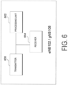
- FIG. 6 is a block diagram illustrating a configuration of a base station apparatus (eNB 102) according to an embodiment of the present invention, which is not covered by the claims. Note that FIG. 6 illustrates only the main components closely related to the present invention in order to avoid complexity of description.
- the eNB 102 illustrated in FIG. 6 includes a transmitter 600 configured to transmit, to the UE 122, an RRC connection reconfiguration message, an RRC connection resume message, an RRC connection setup message, an RRC connection rejection message, an RRC connection release message, and the like, a processing unit 602 configured to cause the processing unit 502 of the UE 122 to perform processing by creating a message including various types of Information Elements (IEs) and transmitting the message to the UE 122, and a receiver 604 configured to receive an RRC connection resume request message and the like from the UE 122.
- IEs Information Elements
- a message transmitted to the UE 122 from the transmitter 600 may be an RRC reconfiguration message, an RRC resume message, an RRC setup message, an RRC rejection message, an RRC release message, or the like.
- the eNB 102 and/or the gNB 108 may separately include a controller configured to control operation of each unit based on various conditions.
- the UE 122 stores or discards the configuration based on the condition of the state transition, whereby appropriate mobility can be achieved.
- the UE 122 can prevent unnecessary cell re-selection priority information discard, by discarding cell re-selection priority information based on a condition in which the state transition is triggered.
- the UE 122 can store or discard the configuration based on the condition of the state transition, and thus appropriate mobility can be achieved.
- a program operating on an apparatus may serve as a program that controls a Central Processing Unit (CPU) and the like to cause a computer to operate in such a manner as to realize the functions of the above-described embodiment according to the present invention.
- Programs or the information handled by the programs are temporarily loaded into a volatile memory such as a Random Access Memory (RAM) while being processed, or stored in a non-volatile memory such as a flash memory, or a Hard Disk Drive (HDD), and then read, modified, and written by the CPU, as necessary.
- RAM Random Access Memory
- HDD Hard Disk Drive
- the apparatuses in the above-described embodiment may be partially enabled by a computer.
- a program for realizing such control functions may be recorded on a computer-readable recording medium to cause a computer system to read the program recorded on the recording medium to perform the program.
- the "computer system” mentioned here refers to a computer system built into the apparatuses, and the computer system includes an operating system and hardware components such as a peripheral device.
- the "computer-readable recording medium” may be any of a semiconductor recording medium, an optical recording medium, a magnetic recording medium, and the like.
- the "computer-readable recording medium” may include a medium that dynamically retains a program for a short period of time, such as a communication line that is used to transmit the program over a network such as the Internet or over a communication line such as a telephone line, and may also include a medium that retains a program for a fixed period of time, such as a volatile memory within the computer system for functioning as a server or a client in such a case.
- the above-described program may be configured to realize some of the functions described above, and additionally may be configured to realize the functions described above, in combination with a program already recorded in the computer system.
- each functional block or various characteristics of the apparatuses used in the above-described embodiment may be implemented or performed with an electric circuit, that is, typically an integrated circuit or multiple integrated circuits.
- An electric circuit designed to perform the functions described in the present specification may include a general purpose processor, a digital signal processor (DSP), an application specific integrated circuit (ASIC), a field programmable gate array (FPGA), or other programmable logic devices, discrete gates or transistor logic, discrete hardware components, or a combination thereof.
- the general-purpose processor may be a microprocessor, or the processor may be a processor of known type, a controller, a microcontroller, or a state machine instead.
- the general-purpose processor or the above-mentioned circuits may include a digital circuit, or may include an analog circuit.
- a circuit integration technology appears that replaces the present integrated circuits, it is also possible to use an integrated circuit based on the technology.
- the invention of the present application is not limited to the above-described embodiment.
- apparatuses have been described as an example in the embodiment, the invention of the present application is not limited to these apparatuses, and is applicable to a stationary type or a non-movable type electronic apparatus installed indoors or outdoors such as a terminal apparatus or a communication apparatus, for example, an AV device, a kitchen device, a cleaning or washing machine, an air-conditioning device, office equipment, a vending machine, and other household appliances.
Landscapes
- Engineering & Computer Science (AREA)
- Computer Networks & Wireless Communication (AREA)
- Signal Processing (AREA)
- Computer Security & Cryptography (AREA)
- Mobile Radio Communication Systems (AREA)
Applications Claiming Priority (2)
| Application Number | Priority Date | Filing Date | Title |
|---|---|---|---|
| JP2019020709A JP6851406B2 (ja) | 2019-02-07 | 2019-02-07 | 端末装置、基地局装置、方法、および、集積回路 |
| PCT/JP2020/004488 WO2020162528A1 (ja) | 2019-02-07 | 2020-02-06 | 端末装置、方法、および、集積回路 |
Publications (3)
| Publication Number | Publication Date |
|---|---|
| EP3923673A1 EP3923673A1 (en) | 2021-12-15 |
| EP3923673A4 EP3923673A4 (en) | 2022-11-02 |
| EP3923673B1 true EP3923673B1 (en) | 2025-04-02 |
Family
ID=71947657
Family Applications (1)
| Application Number | Title | Priority Date | Filing Date |
|---|---|---|---|
| EP20752303.6A Active EP3923673B1 (en) | 2019-02-07 | 2020-02-06 | Terminal apparatus, method, and integrated circuit for management of priority information for cell reselection |
Country Status (5)
| Country | Link |
|---|---|
| US (1) | US11950311B2 (enExample) |
| EP (1) | EP3923673B1 (enExample) |
| JP (1) | JP6851406B2 (enExample) |
| CN (1) | CN113396636B (enExample) |
| WO (1) | WO2020162528A1 (enExample) |
Families Citing this family (4)
| Publication number | Priority date | Publication date | Assignee | Title |
|---|---|---|---|---|
| WO2020198272A1 (en) * | 2019-03-28 | 2020-10-01 | Kyocera Corporation | Resume failure report for failed attempt to resume connected state from inactive state |
| CN114760712A (zh) * | 2021-01-08 | 2022-07-15 | 大唐移动通信设备有限公司 | 数据发送处理方法、装置及处理器可读存储介质 |
| CN116437302B (zh) * | 2021-10-22 | 2024-07-05 | 华为技术有限公司 | 一种通信方法、装置和存储介质 |
| CN117119542A (zh) * | 2023-08-04 | 2023-11-24 | 华为技术有限公司 | 一种通信方法及通信装置 |
Family Cites Families (13)
| Publication number | Priority date | Publication date | Assignee | Title |
|---|---|---|---|---|
| KR101119715B1 (ko) * | 2007-10-05 | 2012-03-23 | 엘지전자 주식회사 | 무선통신 시스템에서 셀 재선택 수행 방법 |
| US9173149B2 (en) * | 2010-10-21 | 2015-10-27 | Lg Electronics Inc. | Method for adjusting cell reselection priority for avoiding IDC interference in wireless communication system and device for same |
| KR101929307B1 (ko) * | 2011-04-11 | 2018-12-17 | 삼성전자 주식회사 | Csg 셀에서 단말이 셀 재선택 우선 순위를 효율적으로 제어하는 방법 및 장치 |
| US8837369B2 (en) * | 2011-07-05 | 2014-09-16 | Mediatek Inc. | System and method for indicating local IP access support via NAS signaling |
| CN103338500A (zh) * | 2012-12-24 | 2013-10-02 | 上海华为技术有限公司 | 一种数据传输方法、装置、系统及网络侧设备和终端设备 |
| US9736765B2 (en) * | 2014-04-28 | 2017-08-15 | Intel IP Corporation | Load balancing in a wireless cellular network based on user equipment mobility |
| US10813019B2 (en) * | 2015-05-13 | 2020-10-20 | Nokia Solutions And Networks Oy | Cell reselection control mechanism in multi-connectivity communication mode |
| WO2018084620A1 (ko) * | 2016-11-04 | 2018-05-11 | 엘지전자 주식회사 | 단말이 셀 재선택 절차를 수행하는 방법 및 이를 지원하는 장치 |
| EP3567926B1 (en) * | 2017-01-05 | 2021-11-10 | Nec Corporation | Base station, wireless terminal, methods therefor, and non-temporary computer-readable medium |
| JP6633780B2 (ja) * | 2017-02-03 | 2020-01-22 | 京セラ株式会社 | 基地局及び方法 |
| JP2019020709A (ja) | 2017-07-12 | 2019-02-07 | 太陽ホールディングス株式会社 | 感光性樹脂組成物、ドライフィルム、硬化物、半導体素子、プリント配線板および電子部品 |
| US20190037635A1 (en) * | 2017-07-28 | 2019-01-31 | Asustek Computer Inc. | Method and apparatus of recovering rrc connection in a wireless communication system |
| WO2023175559A1 (en) * | 2022-03-16 | 2023-09-21 | Lenovo (Singapore) Pte. Ltd. | Configuring measurement and reporting based on a frequency |
-
2019
- 2019-02-07 JP JP2019020709A patent/JP6851406B2/ja active Active
-
2020
- 2020-02-06 CN CN202080012822.5A patent/CN113396636B/zh active Active
- 2020-02-06 WO PCT/JP2020/004488 patent/WO2020162528A1/ja not_active Ceased
- 2020-02-06 US US17/428,657 patent/US11950311B2/en active Active
- 2020-02-06 EP EP20752303.6A patent/EP3923673B1/en active Active
Also Published As
| Publication number | Publication date |
|---|---|
| WO2020162528A1 (ja) | 2020-08-13 |
| US20220132619A1 (en) | 2022-04-28 |
| EP3923673A1 (en) | 2021-12-15 |
| JP6851406B2 (ja) | 2021-03-31 |
| CN113396636B (zh) | 2024-01-23 |
| EP3923673A4 (en) | 2022-11-02 |
| US11950311B2 (en) | 2024-04-02 |
| JP2020129719A (ja) | 2020-08-27 |
| CN113396636A (zh) | 2021-09-14 |
Similar Documents
| Publication | Publication Date | Title |
|---|---|---|
| CN110431859B (zh) | 用于无线通信系统中层之间交互的方法及其设备 | |
| CN119584239A (zh) | 支持用户设备到网络中继通信的方法和设备 | |
| EP3923673B1 (en) | Terminal apparatus, method, and integrated circuit for management of priority information for cell reselection | |
| US20220038929A1 (en) | Terminal device, base station device, method, and integrated circuit | |
| US11665769B2 (en) | Method and apparatus for supporting UE-to-network relay communication in a wireless communication system | |
| WO2020204092A1 (ja) | ユーザ装置、制御装置、及び通信制御方法 | |
| JP7608044B2 (ja) | 端末装置、基地局装置、方法、および、集積回路 | |
| JP7329358B2 (ja) | Ue、及び通信制御方法 | |
| WO2021060383A1 (ja) | ユーザ装置、及びコアネットワーク装置 | |
| US12250744B2 (en) | Method and apparatus for supporting UE-to-network relay communication in a wireless communication system | |
| US11638197B1 (en) | Method and apparatus for supporting UE-to-network relay communication in a wireless communication system | |
| JP7777081B2 (ja) | 端末装置、基地局装置、および、方法 | |
| JP7350508B2 (ja) | Ue、及び通信制御方法 | |
| WO2020095851A1 (ja) | 端末装置、基地局装置、通信方法、および、集積回路 | |
| CN113302977B (zh) | 终端装置、基站装置以及通信方法 | |
| JP2020137084A (ja) | 端末装置、基地局装置、方法、および、集積回路 | |
| US11917462B2 (en) | Terminal apparatus and method | |
| US20220167238A1 (en) | Terminal device, base station device, and communication method | |
| WO2020166310A1 (ja) | 端末装置、および、方法 |
Legal Events
| Date | Code | Title | Description |
|---|---|---|---|
| STAA | Information on the status of an ep patent application or granted ep patent |
Free format text: STATUS: THE INTERNATIONAL PUBLICATION HAS BEEN MADE |
|
| PUAI | Public reference made under article 153(3) epc to a published international application that has entered the european phase |
Free format text: ORIGINAL CODE: 0009012 |
|
| STAA | Information on the status of an ep patent application or granted ep patent |
Free format text: STATUS: REQUEST FOR EXAMINATION WAS MADE |
|
| 17P | Request for examination filed |
Effective date: 20210819 |
|
| AK | Designated contracting states |
Kind code of ref document: A1 Designated state(s): AL AT BE BG CH CY CZ DE DK EE ES FI FR GB GR HR HU IE IS IT LI LT LU LV MC MK MT NL NO PL PT RO RS SE SI SK SM TR |
|
| DAV | Request for validation of the european patent (deleted) | ||
| DAX | Request for extension of the european patent (deleted) | ||
| A4 | Supplementary search report drawn up and despatched |
Effective date: 20221004 |
|
| RIC1 | Information provided on ipc code assigned before grant |
Ipc: H04W 88/02 20090101ALN20220927BHEP Ipc: H04W 76/27 20180101ALI20220927BHEP Ipc: H04W 48/16 20090101AFI20220927BHEP |
|
| REG | Reference to a national code |
Ref country code: DE Ref legal event code: R079 Free format text: PREVIOUS MAIN CLASS: H04W0076270000 Ipc: H04W0048160000 Ref country code: DE Ref legal event code: R079 Ref document number: 602020048741 Country of ref document: DE Free format text: PREVIOUS MAIN CLASS: H04W0076270000 Ipc: H04W0048160000 |
|
| RIC1 | Information provided on ipc code assigned before grant |
Ipc: H04W 88/02 20090101ALN20240802BHEP Ipc: H04W 76/27 20180101ALI20240802BHEP Ipc: H04W 48/16 20090101AFI20240802BHEP |
|
| GRAP | Despatch of communication of intention to grant a patent |
Free format text: ORIGINAL CODE: EPIDOSNIGR1 |
|
| STAA | Information on the status of an ep patent application or granted ep patent |
Free format text: STATUS: GRANT OF PATENT IS INTENDED |
|
| RIC1 | Information provided on ipc code assigned before grant |
Ipc: H04W 88/02 20090101ALN20240812BHEP Ipc: H04W 76/27 20180101ALI20240812BHEP Ipc: H04W 48/16 20090101AFI20240812BHEP |
|
| INTG | Intention to grant announced |
Effective date: 20240916 |
|
| GRAS | Grant fee paid |
Free format text: ORIGINAL CODE: EPIDOSNIGR3 |
|
| GRAA | (expected) grant |
Free format text: ORIGINAL CODE: 0009210 |
|
| STAA | Information on the status of an ep patent application or granted ep patent |
Free format text: STATUS: THE PATENT HAS BEEN GRANTED |
|
| AK | Designated contracting states |
Kind code of ref document: B1 Designated state(s): AL AT BE BG CH CY CZ DE DK EE ES FI FR GB GR HR HU IE IS IT LI LT LU LV MC MK MT NL NO PL PT RO RS SE SI SK SM TR |
|
| REG | Reference to a national code |
Ref country code: GB Ref legal event code: FG4D |
|
| REG | Reference to a national code |
Ref country code: CH Ref legal event code: EP |
|
| REG | Reference to a national code |
Ref country code: IE Ref legal event code: FG4D |
|
| REG | Reference to a national code |
Ref country code: DE Ref legal event code: R096 Ref document number: 602020048741 Country of ref document: DE |
|
| REG | Reference to a national code |
Ref country code: NL Ref legal event code: MP Effective date: 20250402 |
|
| PG25 | Lapsed in a contracting state [announced via postgrant information from national office to epo] |
Ref country code: NL Free format text: LAPSE BECAUSE OF FAILURE TO SUBMIT A TRANSLATION OF THE DESCRIPTION OR TO PAY THE FEE WITHIN THE PRESCRIBED TIME-LIMIT Effective date: 20250402 |
|
| REG | Reference to a national code |
Ref country code: AT Ref legal event code: MK05 Ref document number: 1782527 Country of ref document: AT Kind code of ref document: T Effective date: 20250402 |
|
| PG25 | Lapsed in a contracting state [announced via postgrant information from national office to epo] |
Ref country code: PT Free format text: LAPSE BECAUSE OF FAILURE TO SUBMIT A TRANSLATION OF THE DESCRIPTION OR TO PAY THE FEE WITHIN THE PRESCRIBED TIME-LIMIT Effective date: 20250804 Ref country code: FI Free format text: LAPSE BECAUSE OF FAILURE TO SUBMIT A TRANSLATION OF THE DESCRIPTION OR TO PAY THE FEE WITHIN THE PRESCRIBED TIME-LIMIT Effective date: 20250402 Ref country code: ES Free format text: LAPSE BECAUSE OF FAILURE TO SUBMIT A TRANSLATION OF THE DESCRIPTION OR TO PAY THE FEE WITHIN THE PRESCRIBED TIME-LIMIT Effective date: 20250402 |
|
| REG | Reference to a national code |
Ref country code: LT Ref legal event code: MG9D |
|
| PG25 | Lapsed in a contracting state [announced via postgrant information from national office to epo] |
Ref country code: GR Free format text: LAPSE BECAUSE OF FAILURE TO SUBMIT A TRANSLATION OF THE DESCRIPTION OR TO PAY THE FEE WITHIN THE PRESCRIBED TIME-LIMIT Effective date: 20250703 Ref country code: NO Free format text: LAPSE BECAUSE OF FAILURE TO SUBMIT A TRANSLATION OF THE DESCRIPTION OR TO PAY THE FEE WITHIN THE PRESCRIBED TIME-LIMIT Effective date: 20250702 |
|
| PG25 | Lapsed in a contracting state [announced via postgrant information from national office to epo] |
Ref country code: PL Free format text: LAPSE BECAUSE OF FAILURE TO SUBMIT A TRANSLATION OF THE DESCRIPTION OR TO PAY THE FEE WITHIN THE PRESCRIBED TIME-LIMIT Effective date: 20250402 |
|
| PG25 | Lapsed in a contracting state [announced via postgrant information from national office to epo] |
Ref country code: BG Free format text: LAPSE BECAUSE OF FAILURE TO SUBMIT A TRANSLATION OF THE DESCRIPTION OR TO PAY THE FEE WITHIN THE PRESCRIBED TIME-LIMIT Effective date: 20250402 |
|
| PG25 | Lapsed in a contracting state [announced via postgrant information from national office to epo] |
Ref country code: HR Free format text: LAPSE BECAUSE OF FAILURE TO SUBMIT A TRANSLATION OF THE DESCRIPTION OR TO PAY THE FEE WITHIN THE PRESCRIBED TIME-LIMIT Effective date: 20250402 |
|
| PG25 | Lapsed in a contracting state [announced via postgrant information from national office to epo] |
Ref country code: AT Free format text: LAPSE BECAUSE OF FAILURE TO SUBMIT A TRANSLATION OF THE DESCRIPTION OR TO PAY THE FEE WITHIN THE PRESCRIBED TIME-LIMIT Effective date: 20250402 |
|
| PG25 | Lapsed in a contracting state [announced via postgrant information from national office to epo] |
Ref country code: RS Free format text: LAPSE BECAUSE OF FAILURE TO SUBMIT A TRANSLATION OF THE DESCRIPTION OR TO PAY THE FEE WITHIN THE PRESCRIBED TIME-LIMIT Effective date: 20250702 |
|
| PG25 | Lapsed in a contracting state [announced via postgrant information from national office to epo] |
Ref country code: IS Free format text: LAPSE BECAUSE OF FAILURE TO SUBMIT A TRANSLATION OF THE DESCRIPTION OR TO PAY THE FEE WITHIN THE PRESCRIBED TIME-LIMIT Effective date: 20250802 |
|
| PG25 | Lapsed in a contracting state [announced via postgrant information from national office to epo] |
Ref country code: LV Free format text: LAPSE BECAUSE OF FAILURE TO SUBMIT A TRANSLATION OF THE DESCRIPTION OR TO PAY THE FEE WITHIN THE PRESCRIBED TIME-LIMIT Effective date: 20250402 |