WO2020162179A1 - Optical system - Google Patents
Optical system Download PDFInfo
- Publication number
- WO2020162179A1 WO2020162179A1 PCT/JP2020/002135 JP2020002135W WO2020162179A1 WO 2020162179 A1 WO2020162179 A1 WO 2020162179A1 JP 2020002135 W JP2020002135 W JP 2020002135W WO 2020162179 A1 WO2020162179 A1 WO 2020162179A1
- Authority
- WO
- WIPO (PCT)
- Prior art keywords
- optical system
- light
- polarization
- wavelength
- color
- Prior art date
Links
Images


Classifications
-
- H—ELECTRICITY
- H04—ELECTRIC COMMUNICATION TECHNIQUE
- H04N—PICTORIAL COMMUNICATION, e.g. TELEVISION
- H04N9/00—Details of colour television systems
- H04N9/12—Picture reproducers
- H04N9/31—Projection devices for colour picture display, e.g. using electronic spatial light modulators [ESLM]
- H04N9/3197—Projection devices for colour picture display, e.g. using electronic spatial light modulators [ESLM] using light modulating optical valves
-
- H—ELECTRICITY
- H04—ELECTRIC COMMUNICATION TECHNIQUE
- H04N—PICTORIAL COMMUNICATION, e.g. TELEVISION
- H04N9/00—Details of colour television systems
- H04N9/12—Picture reproducers
- H04N9/31—Projection devices for colour picture display, e.g. using electronic spatial light modulators [ESLM]
- H04N9/3141—Constructional details thereof
- H04N9/315—Modulator illumination systems
- H04N9/3167—Modulator illumination systems for polarizing the light beam
-
- G—PHYSICS
- G02—OPTICS
- G02B—OPTICAL ELEMENTS, SYSTEMS OR APPARATUS
- G02B27/00—Optical systems or apparatus not provided for by any of the groups G02B1/00 - G02B26/00, G02B30/00
- G02B27/28—Optical systems or apparatus not provided for by any of the groups G02B1/00 - G02B26/00, G02B30/00 for polarising
- G02B27/283—Optical systems or apparatus not provided for by any of the groups G02B1/00 - G02B26/00, G02B30/00 for polarising used for beam splitting or combining
-
- G—PHYSICS
- G02—OPTICS
- G02B—OPTICAL ELEMENTS, SYSTEMS OR APPARATUS
- G02B27/00—Optical systems or apparatus not provided for by any of the groups G02B1/00 - G02B26/00, G02B30/00
- G02B27/28—Optical systems or apparatus not provided for by any of the groups G02B1/00 - G02B26/00, G02B30/00 for polarising
- G02B27/286—Optical systems or apparatus not provided for by any of the groups G02B1/00 - G02B26/00, G02B30/00 for polarising for controlling or changing the state of polarisation, e.g. transforming one polarisation state into another
-
- G—PHYSICS
- G02—OPTICS
- G02B—OPTICAL ELEMENTS, SYSTEMS OR APPARATUS
- G02B5/00—Optical elements other than lenses
- G02B5/04—Prisms
-
- G—PHYSICS
- G02—OPTICS
- G02B—OPTICAL ELEMENTS, SYSTEMS OR APPARATUS
- G02B5/00—Optical elements other than lenses
- G02B5/30—Polarising elements
-
- G—PHYSICS
- G02—OPTICS
- G02B—OPTICAL ELEMENTS, SYSTEMS OR APPARATUS
- G02B5/00—Optical elements other than lenses
- G02B5/30—Polarising elements
- G02B5/3083—Birefringent or phase retarding elements
-
- G—PHYSICS
- G03—PHOTOGRAPHY; CINEMATOGRAPHY; ANALOGOUS TECHNIQUES USING WAVES OTHER THAN OPTICAL WAVES; ELECTROGRAPHY; HOLOGRAPHY
- G03B—APPARATUS OR ARRANGEMENTS FOR TAKING PHOTOGRAPHS OR FOR PROJECTING OR VIEWING THEM; APPARATUS OR ARRANGEMENTS EMPLOYING ANALOGOUS TECHNIQUES USING WAVES OTHER THAN OPTICAL WAVES; ACCESSORIES THEREFOR
- G03B21/00—Projectors or projection-type viewers; Accessories therefor
- G03B21/005—Projectors using an electronic spatial light modulator but not peculiar thereto
-
- G—PHYSICS
- G03—PHOTOGRAPHY; CINEMATOGRAPHY; ANALOGOUS TECHNIQUES USING WAVES OTHER THAN OPTICAL WAVES; ELECTROGRAPHY; HOLOGRAPHY
- G03B—APPARATUS OR ARRANGEMENTS FOR TAKING PHOTOGRAPHS OR FOR PROJECTING OR VIEWING THEM; APPARATUS OR ARRANGEMENTS EMPLOYING ANALOGOUS TECHNIQUES USING WAVES OTHER THAN OPTICAL WAVES; ACCESSORIES THEREFOR
- G03B21/00—Projectors or projection-type viewers; Accessories therefor
- G03B21/14—Details
- G03B21/20—Lamp housings
- G03B21/2006—Lamp housings characterised by the light source
- G03B21/2033—LED or laser light sources
- G03B21/204—LED or laser light sources using secondary light emission, e.g. luminescence or fluorescence
-
- G—PHYSICS
- G03—PHOTOGRAPHY; CINEMATOGRAPHY; ANALOGOUS TECHNIQUES USING WAVES OTHER THAN OPTICAL WAVES; ELECTROGRAPHY; HOLOGRAPHY
- G03B—APPARATUS OR ARRANGEMENTS FOR TAKING PHOTOGRAPHS OR FOR PROJECTING OR VIEWING THEM; APPARATUS OR ARRANGEMENTS EMPLOYING ANALOGOUS TECHNIQUES USING WAVES OTHER THAN OPTICAL WAVES; ACCESSORIES THEREFOR
- G03B21/00—Projectors or projection-type viewers; Accessories therefor
- G03B21/14—Details
- G03B21/20—Lamp housings
- G03B21/2066—Reflectors in illumination beam
-
- G—PHYSICS
- G03—PHOTOGRAPHY; CINEMATOGRAPHY; ANALOGOUS TECHNIQUES USING WAVES OTHER THAN OPTICAL WAVES; ELECTROGRAPHY; HOLOGRAPHY
- G03B—APPARATUS OR ARRANGEMENTS FOR TAKING PHOTOGRAPHS OR FOR PROJECTING OR VIEWING THEM; APPARATUS OR ARRANGEMENTS EMPLOYING ANALOGOUS TECHNIQUES USING WAVES OTHER THAN OPTICAL WAVES; ACCESSORIES THEREFOR
- G03B21/00—Projectors or projection-type viewers; Accessories therefor
- G03B21/14—Details
- G03B21/20—Lamp housings
- G03B21/2073—Polarisers in the lamp house
-
- G—PHYSICS
- G03—PHOTOGRAPHY; CINEMATOGRAPHY; ANALOGOUS TECHNIQUES USING WAVES OTHER THAN OPTICAL WAVES; ELECTROGRAPHY; HOLOGRAPHY
- G03B—APPARATUS OR ARRANGEMENTS FOR TAKING PHOTOGRAPHS OR FOR PROJECTING OR VIEWING THEM; APPARATUS OR ARRANGEMENTS EMPLOYING ANALOGOUS TECHNIQUES USING WAVES OTHER THAN OPTICAL WAVES; ACCESSORIES THEREFOR
- G03B21/00—Projectors or projection-type viewers; Accessories therefor
- G03B21/14—Details
- G03B21/28—Reflectors in projection beam
-
- G—PHYSICS
- G03—PHOTOGRAPHY; CINEMATOGRAPHY; ANALOGOUS TECHNIQUES USING WAVES OTHER THAN OPTICAL WAVES; ELECTROGRAPHY; HOLOGRAPHY
- G03B—APPARATUS OR ARRANGEMENTS FOR TAKING PHOTOGRAPHS OR FOR PROJECTING OR VIEWING THEM; APPARATUS OR ARRANGEMENTS EMPLOYING ANALOGOUS TECHNIQUES USING WAVES OTHER THAN OPTICAL WAVES; ACCESSORIES THEREFOR
- G03B33/00—Colour photography, other than mere exposure or projection of a colour film
- G03B33/10—Simultaneous recording or projection
- G03B33/12—Simultaneous recording or projection using beam-splitting or beam-combining systems, e.g. dichroic mirrors
-
- H—ELECTRICITY
- H04—ELECTRIC COMMUNICATION TECHNIQUE
- H04N—PICTORIAL COMMUNICATION, e.g. TELEVISION
- H04N13/00—Stereoscopic video systems; Multi-view video systems; Details thereof
- H04N13/30—Image reproducers
- H04N13/324—Colour aspects
-
- H—ELECTRICITY
- H04—ELECTRIC COMMUNICATION TECHNIQUE
- H04N—PICTORIAL COMMUNICATION, e.g. TELEVISION
- H04N13/00—Stereoscopic video systems; Multi-view video systems; Details thereof
- H04N13/30—Image reproducers
- H04N13/332—Displays for viewing with the aid of special glasses or head-mounted displays [HMD]
- H04N13/337—Displays for viewing with the aid of special glasses or head-mounted displays [HMD] using polarisation multiplexing
-
- H—ELECTRICITY
- H04—ELECTRIC COMMUNICATION TECHNIQUE
- H04N—PICTORIAL COMMUNICATION, e.g. TELEVISION
- H04N13/00—Stereoscopic video systems; Multi-view video systems; Details thereof
- H04N13/30—Image reproducers
- H04N13/363—Image reproducers using image projection screens
-
- H—ELECTRICITY
- H04—ELECTRIC COMMUNICATION TECHNIQUE
- H04N—PICTORIAL COMMUNICATION, e.g. TELEVISION
- H04N9/00—Details of colour television systems
- H04N9/12—Picture reproducers
- H04N9/31—Projection devices for colour picture display, e.g. using electronic spatial light modulators [ESLM]
- H04N9/3102—Projection devices for colour picture display, e.g. using electronic spatial light modulators [ESLM] using two-dimensional electronic spatial light modulators
- H04N9/3105—Projection devices for colour picture display, e.g. using electronic spatial light modulators [ESLM] using two-dimensional electronic spatial light modulators for displaying all colours simultaneously, e.g. by using two or more electronic spatial light modulators
-
- H—ELECTRICITY
- H04—ELECTRIC COMMUNICATION TECHNIQUE
- H04N—PICTORIAL COMMUNICATION, e.g. TELEVISION
- H04N9/00—Details of colour television systems
- H04N9/12—Picture reproducers
- H04N9/31—Projection devices for colour picture display, e.g. using electronic spatial light modulators [ESLM]
- H04N9/3102—Projection devices for colour picture display, e.g. using electronic spatial light modulators [ESLM] using two-dimensional electronic spatial light modulators
- H04N9/3111—Projection devices for colour picture display, e.g. using electronic spatial light modulators [ESLM] using two-dimensional electronic spatial light modulators for displaying the colours sequentially, e.g. by using sequentially activated light sources
-
- H—ELECTRICITY
- H04—ELECTRIC COMMUNICATION TECHNIQUE
- H04N—PICTORIAL COMMUNICATION, e.g. TELEVISION
- H04N9/00—Details of colour television systems
- H04N9/12—Picture reproducers
- H04N9/31—Projection devices for colour picture display, e.g. using electronic spatial light modulators [ESLM]
- H04N9/3141—Constructional details thereof
- H04N9/315—Modulator illumination systems
- H04N9/3158—Modulator illumination systems for controlling the spectrum
Definitions
- the present disclosure relates to an optical system suitable for a projector or the like.
- Patent Document 1 proposes to extend the life of the light valve by using two light valves for blue light.
- An optical system has a first optical element that includes a plurality of divided areas, each of which has a polarization effect different from each other, and includes a first optical element at a first pupil position in an optical system.
- a first optical system in which elements are arranged to generate illumination light including a plurality of color lights having different wavelength bands, and a plurality of lights each modulating at least one of the plurality of color lights included in the illumination light.
- a second optical element having a bulb and a plurality of divided areas each having a different polarization action, and the second optical element is arranged at a second pupil position which is conjugate to the first pupil position; And a second optical system on which a plurality of color lights after being modulated by the light valve are incident.
- a first optical element including a plurality of divided regions having different polarization effects is arranged at a first pupil position. ..
- a second optical element including a plurality of divided areas each having a different polarization action is arranged at a second pupil position which is conjugate with the first pupil position.
- FIG. 1 is a configuration diagram schematically showing an overall configuration example of an optical system according to a first embodiment of the present disclosure. It is a block diagram which shows schematically an example of the fluorescent substance wheel in the optical system which concerns on 1st Embodiment. It is explanatory drawing which shows an example of a structure and an effect
- the blue band light can be split into two light valves in the configuration example disclosed in Patent Document 1, the polarization of the light emitted from each light valve is orthogonal to each other. This means that the contrast cannot be increased by using a post-polarizer in the projection optical system to be used later, which is a problem in realizing high contrast.
- wavelength separation (color separation) using a dichroic mirror requires steep separation characteristics in the vicinity of the separation wavelength range, and is extremely difficult to manufacture.
- Patent Document 2 Japanese Patent Laid-Open No. 2001-324762
- a method of realizing high wavelength separation efficiency by utilizing the pupil distribution is also known.
- the single plate single light valve
- the filters of the respective colors since the single plate (single light valve) is driven field-sequentially through the filters of the respective colors, the light utilization efficiency as a whole becomes low even though the wavelength separation efficiency is good.
- the present disclosure presents a novel technique of optical separation and photosynthesis using pupil conjugation as a method of optical branching.
- the present technology can be used in various ways, but has the following merits.
- the efficiency can be greatly increased.
- the wavelength separation efficiency can be kept higher than that of the wavelength selection wavelength plate, the light utilization efficiency as a whole can be improved.
- the post-polarizer action can be selectively applied to the light emitted from each light valve, and the contrast can be increased.
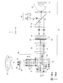
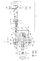
- FIG. 1 schematically shows an overall configuration example of an optical system according to a first embodiment of the present disclosure.
- the first embodiment a configuration example using two light valves is presented.
- the blue light is branched into two light valves to halve the blue light amount and prolong the life.
- the purpose is to increase the contrast.
- the optical system according to the first embodiment includes an illumination optical system 1 and a projection optical system 2. Further, the optical system according to the first embodiment includes a first light valve 31 and a second light valve 32, a PBS (polarized beam) on the optical path between the illumination optical system 1 and the projection optical system 2. Splitter 41).
- the illumination optical system 1 includes a blue light source 10, a phosphor wheel 11, a condenser lens 12, a QWP (1/4 wavelength plate) 13, a wavelength selective PBS 14, a notch filter 15, and a lens array 16. It has a PS converter 17, a first area division wavelength selective wavelength plate 51, and a relay lens 18.
- the projection optical system 2 has a plurality of lenses 21, a second area division wavelength selective wavelength plate 52, and a post polarizer 22.
- the direction orthogonal to the paper surface is S-polarized light for the PBS 41
- the direction orthogonal to the optical axis and parallel to the paper surface is P-polarized light for the PBS 41.
- the direction corresponding to the S-polarized light for the PBS 41 is appropriately referred to as the Z direction
- the direction corresponding to the P-polarized light for the PBS 41 is referred to as the Y direction.
- the illumination optical system 1 corresponds to a specific example of “first optical system” in the technique of the present disclosure.
- the projection optical system 2 corresponds to a specific but not limitative example of “second optical system” in the technology of the present disclosure.
- the first area division wavelength selective wave plate 51 corresponds to a specific but not limitative example of “first optical element” in the technology of the present disclosure.
- the second region division wavelength selective wavelength plate 52 corresponds to a specific but not limitative example of “second optical element” in the technology of the present disclosure.
- the illumination optical system 1 generates illumination light including a plurality of color lights having different wavelength bands.
- the illumination optical system 1 has a wavelength separation function of separating light in at least one wavelength band into a plurality of color lights.
- the illumination optical system 1 generates R, G, and B color lights as a plurality of color lights and emits them toward the PBS 41.
- the first area division wavelength selective wave plate 51 is arranged at the pupil position P1 of the illumination optical system 1.
- the first area-divided wavelength-selective wave plate 51 includes a plurality of divided areas each having a different polarization action.
- the plurality of divided areas in the first area-divided wavelength selective wavelength plate 51 are, for example, areas A and B shown in FIG. 3 described later.
- the PBS 41 makes each color light from the illumination optical system 1 incident on at least one of the first light valve 31 and the second light valve 32 according to the polarization direction.
- the PBS 41 makes the blue light enter the first light valve 31 and the second light valve 32, for example, by branching the blue light according to the difference in polarization.
- the PBS 41 also causes green light to enter one of the first light valve 31 and the second light valve 32 (first light valve 31), for example.
- the PBS 41 also causes red light to enter the other light valve (second light valve 32) of the first light valve 31 and the second light valve 32, for example. Further, the PBS 41 emits each color light modulated by the first light valve 31 and the second light valve 32 toward the projection optical system 2 according to the polarization direction.
- Each of the first light valve 31 and the second light valve 32 modulates at least one color light of the plurality of color lights according to, for example, an image signal.
- Each color light after being modulated by the first light valve 31 and the second light valve 32 enters the projection optical system 2 via the PBS 41.
- the projection optical system 2 projects the image generated by the first light valve 31 and the second light valve 32 onto a projection surface such as a screen (not shown).
- the second area division wavelength selective wavelength plate 52 is arranged at the pupil position P2 of the projection optical system 2.
- the second area-divided wavelength-selective wave plate 52 includes a plurality of divided areas each having a different polarization effect.
- the plurality of divided areas in the second area-divided wavelength selective wavelength plate 52 are, for example, A′ area and B′ area shown in FIG. 4 described later.
- the pupil position P1 of the illumination optical system 1 and the pupil position P2 of the projection optical system 2 are conjugate with each other.
- Each of the plurality of divided areas in the first area-divided wavelength selective wavelength plate 51 and each of the plurality of divided areas in the second area-divided wavelength selective wavelength plate 52 are conjugated with each other.
- the pupil position P1 of the illumination optical system 1 corresponds to a specific example of “first pupil position” in the technique of the present disclosure.
- the pupil position P2 of the projection optical system 2 corresponds to a specific but not limitative example of “second pupil position” in the technique of the present disclosure.
- the post-polarizer 22 is arranged on the emission optical path of the second area division wavelength selective wavelength plate 52.
- FIG. 2 schematically shows a configuration example of the phosphor wheel 11.
- FIG. 3 shows an example of the configuration and operation of the first area division wavelength selective wave plate 51.
- FIG. 4 shows an example of the configuration and operation of the second area division wavelength selective wave plate 52.
- the blue light source 10 is, for example, a blue laser.
- the phosphor wheel 11 has a phosphor region 111 and a polarization maintaining diffusion plate region 112. By irradiating the phosphor region 111 with blue light as excitation light, yellow (Ye) light is obtained.
- the polarization maintaining diffusion plate region 112 has a reflecting function for blue light without a polarizing effect. For this reason, the phosphor wheel 11 emits time-averaged white light that is a temporal repetition of yellow, blue, yellow, blue,....
- the blue light emitted from the blue light source 10 is reflected by the wavelength-selective PBS 14, passes through the quarter-wave plate 13 to become circularly polarized light, and then enters the phosphor wheel 11 via the condenser lens 12. ..
- the light emitted from the phosphor wheel 11 passes through the quarter-wave plate 13 again to be converted into P-polarized light for the wavelength-selective PBS 14. Then, the light is emitted to the transmission side by the wavelength-selective PBS 14.
- the yellow light extracted from the phosphor wheel 11 is also reflected and then emitted to the transmission side by the wavelength selective PBS 14.
- the yellow light generated by the phosphor wheel 11 is in a non-polarized state, and the wavelength selective PBS 14 has a function of transmitting all the yellow light.
- the blue light and the yellow light emitted from the wavelength-selective PBS 14 pass through the notch filter 15 and the lens array 16 and then pass through the PS converter 17 so that the polarization state is one direction (for example, polarization in the Y direction (P-polarized light here). )).
- the first area-divided wavelength selective wavelength plate 51 having the characteristics as shown in FIG. 3 is arranged in the portion where the pupil (first pupil) of the illumination optical system 1 is formed.
- the first region-divided wavelength-selective wave plate 51 is, for example, a 1/2 wave plate arranged in an oblique 45 deg where the upper half (A region) acts only on green, and the lower half (B region) is green.
- the polarized light of blue light is in a mixed state of polarized light that does not rotate (polarized light in the Y direction (P polarized light)) and polarized light that rotates (polarized light in the Z direction (S polarized light)).
- each color light After passing through the first area-divided wavelength-selective wave plate 51, when the light flux of each color reaches the PBS 41 through the relay lens 18, each color light is selectively emitted in accordance with each polarization state of the first light valve 31 and the second light valve 31. It is led to the light valve 32.
- the red light is P-polarized light and reaches the second light valve 32
- the green light is S-polarized light and reaches the first light valve 31.
- the blue light is in a mixed state of P-polarized light and S-polarized light, and reaches the first light valve 31 and the second light valve 32 in half and half.
- the first light valve 31 and the second light valve 32 When a reflective liquid crystal is used for the first light valve 31 and the second light valve 32, when the white display is performed by each light valve, each polarization rotation occurs, and each incident polarization becomes an exit polarization in an orthogonal state. Changes. Therefore, the first light valve 31 emits red light and blue light as S-polarized light, and the second light valve 32 emits blue light and red light as P-polarized light. Therefore, when white display is performed, all the light passing through the PBS 41 is emitted to the projection optical system 2 side.
- the PBS 41 tends to have a slightly larger Rp (reflection P polarization component) than Ts (transmission S polarization component) due to the characteristics of the polarizing film. Therefore, the second light valve 32 side tends to have less contrast than the first light valve 31 side. This is because more P-polarized light generated by the second light valve 32 leaks to the projection optical system 2 side than S-polarized light generated by the first light valve 31 during black display.
- the contrast is increased, and only the first light valve 31 side is used.
- the contrast is greatly increased. It becomes a factor to lose.
- the post-polarizer 22 (after injection of the PBS 41 is used. It is necessary to align the direction of polarization with the analyzer (1) to improve the contrast.
- the post-polarizer 22 is arranged immediately after the PBS 41 without devising, the amount of light will be halved because the polarization states of blue light are orthogonal.
- the greatest feature of the optical system according to the first embodiment is to improve this by utilizing the conjugate action of the pupil.
- the second area division wavelength selective wavelength plate 52 is arranged at the pupil (second pupil) position P2 of the projection optical system 2 after the emission from the PBS 41. ..
- the dividing method at this time is shown in FIG.
- the pupil of the projection optical system 2 is conjugate with the pupil of the illumination optical system 1, and since it passes through the light valve reflection, the vertical inversion corresponds to each conjugate part in a region. Therefore, as shown in FIG. 4, the area conjugate to the area A of the first area-divided wavelength-selective wave plate 51 is the A′ area below the second area-divided wavelength-selective wave plate 52.
- the region conjugate to the B region of the first region-divided wavelength selective wavelength plate 51 is the B′ region above the second region-divided wavelength selective wavelength plate 52.
- Conjugation means that light that has passed through the area A of the first area-divided wavelength-selective wave plate 51 always passes through the area A′ of the second area-divided wavelength-selective wave plate 52 and has the first area-divided wavelength selectivity.
- Light that has passed through the B region of the wave plate 51 always passes through the B′ region of the second area-divided wavelength selective wave plate 52. Therefore, of the mixed blue light, the P-polarized light is selectively incident on the B'region and the S-polarized light is selectively incident on the A'region.
- the polarization of the blue light is not converted in the A'region, and the polarization of the blue light is rotated by 90 deg in the B'region.
- the polarized light of the red light does not rotate and the polarized light of the green light rotates by 90 deg in any of the regions, as a result, the polarized light of each color light after passing through the second area-divided wavelength selective wavelength plate 52 becomes S-polarized light. Will be unified.
- the contrast can be improved by arranging the post polarizer 22 so as to cut the P-polarized light after passing through the second area-divided wavelength-selective wave plate 52.
- an experimental result of white contrast of about 1000:1 at F/2.5 was obtained, and the amount of blue light was about half each. It was confirmed that the first light valve 31 and the second light valve 32 could be branched to exhibit the expected operation.
- the main purpose of this is to divide the blue light, which is the cause of shortening the life of the light valve, into two, thereby reducing the amount of incident light by half and significantly improving the life of the entire optical system. In this sense, it is desirable that the light split into two is 500 nm or less.
- Patent Document 3 Japanese Patent Laid-Open No. 2008-165058.
- a region-divided retardation plate is arranged in the vicinity of the pupil in the projection optical system, and light is split into two by polarized light in the projection optical system.
- the pupil position P1 of the illumination optical system 1 includes the first area division wavelength including the plurality of division areas having different polarization effects.
- the optical system according to the first embodiment it is possible to increase the contrast, and it is possible to prevent color unevenness on the projection surface by aligning the polarization of the final emitted light in the projection optical system 2 in one direction. Further, since the contrast can be increased for one PBS 41 while using two light valves, it is possible to reduce the size of the entire optical system as a result.
- the notch filter 15 is an essential component in the illumination optical system 1. The role of the notch filter 15 will be described with reference to FIGS.
- FIG. 5 shows an example of the fluorescence spectrum of the YAG phosphor used in the phosphor wheel 11 in the optical system according to the first embodiment.
- FIG. 6 shows wavelength selection characteristics of the B area of the first area-divided wavelength selective wavelength plate 51 and the B′ area of the second area-divided wavelength selective wavelength plate 52 in the optical system according to the first embodiment. Shows an example.
- FIG. 7 shows the wavelength selection characteristics of the A area of the first area-divided wavelength selective wavelength plate 51 and the A′ area of the second area-divided wavelength selective wavelength plate 52 in the optical system according to the first embodiment. Shows an example.
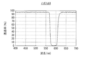
- FIG. 8 shows an example of the characteristics of the notch filter 15 in the optical system according to the first embodiment.
- the polarized light of each color is selectively rotated.
- a problem is the switching region between red and green of 575 nm to 610 nm.
- the conversion efficiency of this portion is not 100% for any polarized light, so that an unintended polarization component appears.
- An unintended polarized component becomes polarized light that cannot be blocked by the post-polarizer 22, which causes a sharp deterioration in contrast.
- the notch filter 15 having the characteristic shown in FIG.
- FIG. 9 shows an example of the fluorescence spectrum after the action of the notch filter 15. It can be seen that there is a considerable spectrum loss as compared with FIG. Further, also in the regions A and A′ shown in FIG. 7, switching between red and green occurs in the region of approximately 575 nm to 610 nm, and shielding of this part is important.
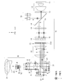
- FIG. 10 schematically shows an example of the overall configuration of the optical system according to the second embodiment.
- the optical system according to the first embodiment includes an illumination optical system 1A and a projection optical system 2A.
- the illumination optical system 1A is different from the configuration of the illumination optical system 1 (FIG. 1) in the first embodiment, in that it replaces the first area division wavelength selective wavelength plate 51 with the pupil position P1 of the illumination optical system 1A.
- the dichroic converter 61 is arranged in the position. Further, the illumination optical system 1A has a configuration in which the notch filter 15 is omitted and a 1/2 wavelength plate 19 is arranged after the wavelength selective PBS 14 in addition to the configuration of the illumination optical system 1 in the first embodiment. ing.
- the dichroic converter 61 includes a plurality of divided areas each having a different polarization effect. The wavelength distributions in each of the plurality of divided areas at the pupil position P1 of the illumination optical system 1A are different from each other.
- the plurality of divided areas in the dichroic converter 61 are, for example, area C and area D shown in FIG. 12, which will be described later.
- the post polarizer 22 is omitted from the configuration of the projection optical system 2 (FIG. 1) in the first embodiment, and instead of the second area division wavelength selective wavelength plate 52,
- the area dividing polarizer 62 is arranged at the pupil position P2 of the projection optical system 2A.
- the area division polarizer 62 includes a plurality of division areas each having a different polarization effect.
- the area division polarizer 62 has a function of transmitting lights having polarization directions different from each other in each of the plurality of division areas.
- the plurality of divided areas in the area-divided polarizer 62 are, for example, a C′ area and a D′ area shown in FIG. 13 described later.
- the area-divided polarizer 62 functions as an area-divided post-polarizer.
- the illumination optical system 1A corresponds to a specific but not limitative example of “first optical system” in the technology of the present disclosure.
- the projection optical system 2A corresponds to a specific but not limitative example of “second optical system” in the technology of the present disclosure.
- the dichroic converter 61 corresponds to a specific but not limitative example of “first optical element” in the technique of the present disclosure.
- the area division polarizer 62 corresponds to a specific but not limitative example of “second optical element” in the technology of the present disclosure.
- the half-wave plate 19 can convert the polarization state of blue light so that the polarization in the Y direction (P polarization) and the polarization in the Z direction (S polarization) are equal.
- the respective color lights entering the PS converter 17 have a polarization state in which the P polarization and the S polarization are in the same state.
- FIG. 11 schematically shows a configuration example of the PS converter 17 and the dichroic converter 61 in the optical system according to the second embodiment.
- the PS converter 17 has a plurality of prism blocks on which a polarizing film 171 is formed.
- shield regions 173 are formed every other one of the plurality of prism blocks in the Y direction.
- a half-wave plate 172 is formed every other prism block in the Y direction.
- the shielding region 173 and the half-wave plate 172 are formed in the same prism block among a plurality of prism blocks.
- the dichroic converter 61 has a plurality of prism blocks.
- the plurality of prism blocks include a first prism block having a dichroic film 611 formed thereon and a second prism block having a total reflection film 614 formed thereon, and the first prism block and the second prism block. And are arranged alternately in the Y direction.
- a half-wave plate 612 is formed on the light exit surface along the X direction of the first prism block on which the dichroic film 611 is formed.
- a shielding region 613 is formed on the light incident surface along the X direction of the second prism block on which the total reflection film 614 is formed.
- the dichroic converter 61 is arranged adjacent to the PS converter 17.
- the PS converter 17 receives unpolarized light, of which the P-polarized component is transmitted and the S-polarized component is reflected. Since the prism block in the PS converter 17 is a polarizing prism, the S polarization component reflected by the polarizing film 171 of a certain prism block is further reflected by the polarizing film 171 of another prism block and passes through the 1 ⁇ 2 wavelength plate 172. By doing so, the P-polarized component is converted again. As a result, the PS converter 17 can convert polarized light.
- the PS converter 17 is arranged on the exit side of the lens array 16, and a shield region 173 is provided between the formed point images to realize the polarization conversion while suppressing the light amount loss. Further, the dichroic converter 61 exerts a color conversion function on the light passing through the PS converter 17. On the prism block forming the dichroic converter 61, dichroic films 611 and total reflection films 614 are alternately formed. On the side of the dichroic film 611, red light is reflected and 50% of blue light is reflected, green light is transmitted, and further 50% of blue light is transmitted. The total reflection film 614 has a function of reflecting all light.
- the light reflected from the dichroic film 611 and further reflected from the total reflection film 614 is converted into green-blue light and red-blue light by passing through the 1 ⁇ 2 wavelength plate 612 that rotates the polarization direction by 90 deg.
- the polarizations may be orthogonal to each other.
- FIG. 12 shows an example of the polarization state in the pupil of the illumination optical system 1A of the optical system according to the second embodiment.
- the divided C area and D area are staggered in the vertical direction.
- the C region corresponds to the region in which the half-wave plate 612 is formed in the dichroic converter 61 shown in FIG.
- the D region corresponds to a region in which the half-wave plate 612 is not formed in the dichroic converter 61 shown in FIG.
- the light passing through the C region is composed of red light having a light amount of 100% and blue light having a light amount of 50%, and the polarization direction is the Y direction (P polarized light).
- the light passing through the region D is composed of green light with a light amount of 100% and blue light with a light amount of 50%, and the polarization direction is the Z direction (S polarization).
- the light emitted from the region C reaches the second light valve 32 because the polarization direction is the Y direction.
- the light emitted from the region D reaches the first light valve 31 because the polarization direction is the Z direction.
- the lights converted into the orthogonal polarizations by the first light valve 31 and the second light valve 32 are subjected to the action of each divided area by the area dividing polarizer 62 in the pupil of the projection optical system 2A. ..
- FIG. 13 shows an example of the polarization state in the pupil of the projection optical system 2A of the optical system according to the second embodiment.
- the divided C'region and D'region are staggered in the vertical direction.
- the portion of the C′ area at the pupil position P2 of the projection optical system 2A is conjugate with the C area at the pupil position P1 of the illumination optical system 1A, and the conjugate of the D area at the pupil position P1 of the illumination optical system 1A is projected.
- This is a portion of the D'region at the pupil position P2 of the optical system 2A. Therefore, only the Y direction (P polarized light) reaches the C'region and only the Z direction (S polarized light) reaches the D'region.
- the area dividing polarizer 62 is provided so that the C′ region is given the polarizer effect of Y direction polarized light transmission and Z direction polarized light shielding, and the D′ region is given the Z direction polarized light transmission and Y direction polarized light shielding polarizer effect.
- the effect as each post polarizer can be given to the first light valve 31 and the second light valve 32, and the contrast can be increased.
- An advantage of the configuration of the optical system according to the second embodiment is that the notch filter 15 is not needed because the first area division wavelength selective wave plate 51 is not used.
- the post-polarizer 22 blocks in the red-green switching area. It can't function as a perfect post-polarizer because it produces polarized light in different directions, which is impossible.
- the conversion of reflection and transmission depending on the polarization direction is not perfect in the switching region between red and green, but the illumination optical system 1A In the pupil, the polarization direction generated depends on whether the light is guided to the C region or the D region.
- the light emitted from the C area is always guided to the C′ area of the pupil of the projection optical system 2A, and the light emitted from the D area is always guided to the D′ area of the pupil of the projection optical system 2A.
- the post-polarizer region-dividing polarizer 62
- the notch filter 15 is not necessary for increasing the contrast. In other words, it is an advantage that the incomplete conversion in the switching region between red and green is not pressed against the polarized light.
- FIG. 14 shows an example of a spectrum of light reaching the first and second light valves 31 and 32 in the optical system according to the second embodiment. It can be seen that the lights in the red and green switching regions are mixed and assigned to each light valve.
- the polarization of each light valve is unidirectional, and mixing of polarization does not occur in principle.
- the light amount loss caused by the notch filter 15 used in the optical system according to the first embodiment is eliminated, and the brightness is improved by about 30%, and the contrast and the panel light resistance are improved. Can be combined.
- the contrast of 1000:1 similar to that of the optical system according to the first embodiment is expected in principle.
- the first area-divided wavelength selective wavelength plate 51 is replaced by the dichroic converter 61, so that the first area-divided wavelength selective wavelength plate is replaced. It is possible to eliminate the conversion loss caused by 51 and maintain a high contrast while greatly increasing the brightness.
- FIG. 15 schematically shows an example of the overall configuration of the optical system according to the third embodiment.
- the configuration example of the optical system capable of improving the contrast while suppressing the light amount loss is shown.
- the PS converter 17 since the PS converter 17 has the shielding region 173, the dichroic converter which is in contact with the PS converter 17 is actually used.
- the loss of the angle component is likely to be large.
- the optical system according to the third embodiment includes an illumination optical system 1B and a projection optical system 2B.
- the illumination optical system 1B has a first lens array 16A and a second lens array 16B instead of the lens array 16 in addition to the configuration of the illumination optical system 1A (FIG. 10) in the second embodiment. doing. Further, the illumination optical system 1B has a first relay lens 18A and a second relay lens 18B instead of the relay lens lens 18 in the configuration of the illumination optical system 1A in the second embodiment. ing. Further, the illumination optical system 1B has a configuration in which the half-wave plate 19 is omitted from the configuration of the illumination optical system 1A in the second embodiment.
- the projection optical system 2B has the same configuration as the projection optical system 2A (FIG. 10) in the second embodiment.
- the illumination optical system 1B corresponds to a specific but not limitative example of “first optical system” in the technology of the present disclosure.
- the projection optical system 2B corresponds to a specific but not limitative example of “second optical system” in the technology of the present disclosure.
- the optical system according to the third embodiment is different from the optical system according to the second embodiment in that the PS converter 17 and the dichroic converter 61 are separated, and the second relay lens 18B and the second relay lens 18B are provided between them.
- the system is such that it is connected to the second lens array 16B.
- uniform illumination is once formed by the first lens array 16A, the PS converter 17, and the second relay lens 18B, and again, the second lens array 16B, the dichroic converter 61, and the first relay lens.
- 18A produces uniform illumination for the first light valve 31 and the second light valve 32.
- the subsequent configuration and operation are similar to those of the optical system according to the second embodiment, and the contrast can be increased by using pupil conjugation.
- the pitches of the PS converter 17 and the dichroic converter 61 can be matched, and as a result, the shielding area 173 of the PS converter 17 can be made smaller, so that the above-mentioned Etendue Since there are almost no problems, the light utilization efficiency can be greatly increased while suppressing the volume of the entire system.
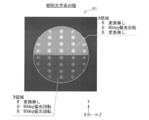
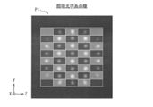
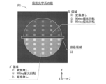
- FIG. 16 shows an example of the pupil shape of the illumination optical system 1A or the projection optical system 2A of the optical system according to the second embodiment as a comparative example with respect to the optical system according to the third embodiment.
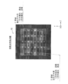
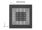
- FIG. 17 shows an example of the pupil shape of the illumination optical system 1B or the projection optical system 2B of the optical system according to the third embodiment.
- the pupil shape in the optical system according to the second embodiment is substantially circular.
- the image in front of the second lens array 16B formed by the first lens array 16A becomes a pupil shape. Therefore, it is almost square. This may adversely affect laser safety standards and the like. In order to solve this, it is more preferable to adopt the configuration of the optical system according to the fourth embodiment described later.
- the pupil distribution for blue light is the same as the pupil distribution for yellow light even when the polarization maintaining diffusion plate region 112 of the phosphor wheel 11 has a simple total reflection configuration. It also has the advantages of cost reduction and simplification of the manufacturing process.
- FIG. 18 schematically shows an example of the overall configuration of the optical system according to the fourth embodiment.
- the optical system according to the fourth embodiment includes an illumination optical system 1C and a projection optical system 2C.
- the illumination optical system 1C includes a first lens array 16A, a second lens array 16B, and a third lens array 16A instead of the lens array 16 in the configuration of the illumination optical system 1A (FIG. 10) in the second embodiment.
- Lens array 16C the illumination optical system 1C is different from the configuration of the illumination optical system 1A in the second embodiment, in place of the relay lens lens 18, a first relay lens 18A, a second relay lens 18B, and a third relay lens 18A. It has a relay lens 18C.
- the illumination optical system 1C has a configuration in which the half-wave plate 19 is omitted from the configuration of the illumination optical system 1A in the second embodiment.
- the projection optical system 2C has the same configuration as the projection optical system 2A (FIG. 10) in the second embodiment.
- the illumination optical system 1C corresponds to a specific but not limitative example of “first optical system” in the technology of the present disclosure.
- the projection optical system 2C corresponds to a specific but not limitative example of “second optical system” in the technology of the present disclosure.
- the optical system according to the fourth embodiment has a relay of the illumination optical system 1C as shown in FIG.
- the lens system has three stages.
- the first lens array 16A is a rectangular lens array
- the second lens array 16B is a hexagonal lens
- the third lens array 16C is a rectangular lens array.
- the first lens array 16A, the PS converter 17, and the third relay lens 18C have a polarization rectifying function.
- the second lens array 16B and the second relay lens 18B generate hexagonal illumination (this becomes a pupil later).
- the third lens array 16C, the dichroic converter 61, and the first relay lens 18A have a function of separating colors, a polarization conversion action for each light valve, and a function of producing uniform rectangular illumination for each light valve.
- the subsequent configuration and operation are similar to those of the second embodiment, and the contrast can be increased by using pupil conjugation.
- FIG. 19 shows an example of the pupil shape of the illumination optical system 1C or the projection optical system 2C of the optical system according to the fourth embodiment.
- the pupil shape can be made to have a configuration close to a hexagon, and the quadrangular shape which is a problem in the above-described third embodiment. You can avoid becoming an eye.
- the optical system according to the fourth embodiment may have a configuration in which the polarization maintaining/diffusing plate region 112 on the phosphor wheel 11 is simply reflected, similarly to the optical system according to the third embodiment. It is possible.
- FIG. 20 schematically shows an example of the overall configuration of the optical system according to the fifth embodiment.
- the optical system according to the fifth embodiment includes an illumination optical system 1D and a projection optical system 2D.
- the illumination optical system 1D is different from the configuration of the illumination optical system 1 (FIG. 1) in the first embodiment, in place of the first area division wavelength selective wavelength plate 51, and the pupil position P1 of the illumination optical system 1D.
- the area division wavelength plate 71 is arranged in the area. Further, the illumination optical system 1D has a configuration in which the notch filter 15 is omitted and a 1 ⁇ 2 wavelength plate 19 is disposed after the wavelength selective PBS 14 in addition to the configuration of the illumination optical system 1 in the first embodiment. ing.
- the area division wavelength plate 71 includes a plurality of division areas each having a different polarization effect. The plurality of divided areas in the area-divided wavelength plate 71 are, for example, a D area and an E area shown in FIG. 21 described later.
- the post polarizer 22 is omitted from the configuration of the projection optical system 2 (FIG. 1) in the first embodiment, and instead of the second area division wavelength selective wavelength plate 52,
- the area dividing polarizer 62 is arranged at the pupil position P2 of the projection optical system 2D.
- the area division polarizer 62 includes a plurality of division areas each having a different polarization effect.
- the area division polarizer 62 has a function of transmitting lights having polarization directions different from each other in each of the plurality of division areas.
- the plurality of divided areas in the area division polarizer 62 are, for example, a D′ area and an E′ area shown in FIG. 22, which will be described later.
- the area-divided polarizer 62 functions as an area-divided post-polarizer.
- the illumination optical system 1D corresponds to a specific but not limitative example of “first optical system” in the technology of the present disclosure.
- the projection optical system 2D corresponds to a specific but not limitative example of “second optical system” in the technology of the present disclosure.
- the area division wavelength plate 71 corresponds to a specific but not limitative example of “first optical element” in the technology of the present disclosure.
- the area division polarizer 62 corresponds to a specific but not limitative example of “second optical element” in the technology of the present disclosure.
- the optical system according to the fifth embodiment can be configured as a 3D (three-dimensional) display device by further including polarization glasses 4 and a polarization maintaining screen 5. An image for the right eye and an image for the left eye are projected on the polarization maintaining screen 5 via the projection optical system 2D.
- the light incident on the PS converter 17 is polarized in the Y direction (P polarized light) and in the Z direction with respect to all colors by previously inserting the 1 ⁇ 2 wavelength plate 19. (S-polarized light) is equal.
- a broadband area-divided wavelength plate 71 having no wavelength selectivity is used, and For the three-dimensional display, the light is divided into all the red, green, and blue color lights.
- the area dividing polarizer 62 is arranged at the pupil position P2 of the projection optical system 2D to increase the contrast while maintaining the polarized light for the right eye and the polarized light for the left eye.
- the polarizing glasses 4 are orthogonal polarizer glasses, and the user can observe the image for the right eye and the image for the left eye projected on the polarization maintaining screen 5 as three-dimensional images by wearing the polarizing glasses 4. It will be possible.
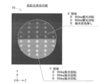
- FIG. 21 shows an example of the polarization state in the pupil of the illumination optical system 1D of the optical system according to the fifth embodiment.
- the area division wavelength plate 71 is vertically divided into a D area and an E area.
- the polarizations of all the color lights are rotated by 90 deg, and in the E region, the polarizations of all the color lights are not rotated at all.
- all the light passing through the D region can reach the first light valve 31, and all the light passing through the E region can reach the second light valve 32.
- the right eye channel and the second light valve 32 can be used as the left eye channel.
- FIG. 22 shows an example of the polarization state in the pupil of the projection optical system 2D of the optical system according to the fifth embodiment.
- the area division polarizer 62 is vertically divided into an E′ area and a D′ area.
- the portion of the D'region at the pupil position P2 of the projection optical system 2D is conjugate with the D region at the pupil position P1 of the illumination optical system 1D, and the conjugate is at the E region of the pupil position P1 of the illumination optical system 1D at the pupil region P1. This is a portion of the E′ region at the pupil position P2 of the optical system 2D.
- the projection optical system 2D all the light from the first light valve 31 reaches the D'region, and the contrast is increased by the action of the polarizer that transmits only the polarized light in the Y direction (P polarized light).
- all the light from the second light valve 32 reaches the E′ region, and the contrast is increased by the action of the polarizer that transmits only the polarized light in the Z direction (S polarized light).
- the optical system according to the fifth embodiment is a two-plate optical system that is compact and can increase the contrast to a practical range, and can also perform polarized three-dimensional display. Therefore, the polarizing glasses 4 can be simplified and lightened, and the entire system can be realized. It is possible to assemble at low cost.
- optical system according to the fifth embodiment does not mean that the boundary between green and red is polarized differently, so the notch filter 15 is unnecessary.
- optical system of the fifth embodiment it is possible to increase the contrast even during three-dimensional display and reduce the amount of crosstalk between the left and right eyes.
- FIG. 23 schematically shows an example of the overall configuration of the optical system according to the sixth embodiment.
- the optical system according to the sixth embodiment includes an illumination optical system 1E and a projection optical system 2E. Further, the optical system according to the sixth embodiment includes two blue light valves 3B1 and 3B2 and one red light valve 3R1 on the optical path between the illumination optical system 1E and the projection optical system 2E. It is provided with one green light valve 3G1, PBSs 41, 42, 43 and a dichroic cube 44.
- the illumination optical system 1E includes a first blue light source 10A, a second blue light source 10B, a phosphor wheel 11, a condenser lens 12, a 1/4 wavelength plate 13, a wavelength selective PBS 14, and a lens array. 16, a PS converter 17, a first area division wavelength selective wavelength plate 51, and a relay lens 18. Further, the illumination optical system 1E has a first color plate 81, a second color plate 82, and a total reflection mirror 83.
- the projection optical system 2E has the same configuration as the projection optical system 2 (FIG. 1) in the first embodiment.
- the illumination optical system 1E corresponds to a specific but not limitative example of “first optical system” in the technology of the present disclosure.
- the projection optical system 2E corresponds to a specific but not limitative example of “second optical system” in the technology of the present disclosure.
- the first area division wavelength selective wave plate 51 corresponds to a specific but not limitative example of “first optical element” in the technology of the present disclosure.
- the second region division wavelength selective wavelength plate 52 corresponds to a specific but not limitative example of “second optical element” in the technology of the present disclosure.
- the PBS 41 corresponds to a specific example of “polarization separation element” in the technique of the present disclosure.
- the PBS 41 is provided on the optical path of the blue light emitted from the illumination optical system 1E, and branches the blue light according to the difference in polarization so that the blue light is incident on the blue light valve 3B1 and the blue light valve 3B2.
- the PBS 42 is provided on the optical path of the red light emitted from the illumination optical system 1E, and causes the red light to enter the red light valve 3R1.
- the PBS 43 is provided on the optical path of the green light emitted from the illumination optical system 1E, and causes the green light to enter the green light valve 3G1.
- the dichroic cube 44 synthesizes the respective color lights modulated by the respective light valves and emits them toward the projection optical system 2E.
- the optical system according to the sixth embodiment has a three-plate configuration of R, G, and B as a basic configuration, and two light valves (blue light valves 3B1 and 3B2) are arranged only for the B channel as a light resistance measure. doing.
- the polarization maintaining diffusion plate region 112 (FIG. 2) is not provided in the phosphor wheel 11, and the blue light from the first blue light source 10A emits fluorescence.
- the body region 111 is continuously irradiated.
- the yellow light is continuously emitted from the phosphor wheel 11 instead of being time-divided.
- Blue light is continuously emitted from the second blue light source 10B.
- the blue light from the second blue light source 10B is reflected by the wavelength selective PBS 14 and combined with the yellow light from the phosphor wheel 11.
- each light valve is dedicated to each color, and color time division is not performed.
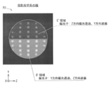
- FIG. 24 shows an example of the polarization state in the pupil of the illumination optical system 1E of the optical system according to the sixth embodiment.
- the first area division wavelength selective wave plate 51 is vertically divided into an F area and a G area.
- the F region rotates the polarized light by 90 deg regardless of the R, G, and B colors, and in the G region, only the blue light is not polarization-converted, and the other colored light is rotated by 90 deg.
- the blue light entering the light valve is halved, and the service life of the system can be extended.
- the red light and the green light are branched by the first color plate 81 and the second color plate 82, and are respectively led to the red light valve 3R1 and the green light valve 3G1.
- the red light and the green light are incident on S-polarized light, and the emitted light is P-polarized light.
- the R, G, and B color lights emitted from the light valves are combined by the dichroic cube 44 and guided to the projection optical system 2E.
- the polarization directions at this time are Y-direction polarization (P-polarization) for red light and green light when incident on the projection optical system 2E, and Y-direction polarization (P-polarization) and Z-direction polarization (S-polarization) for blue light. And are mixed.
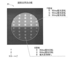
- FIG. 25 shows an example of the polarization state in the pupil of the projection optical system 2E of the optical system according to the sixth embodiment.
- the second area-divided wavelength selective wavelength plate 52 is vertically divided into a G′ area and an F′ area.
- the F region at the pupil position P1 of the illumination optical system 1E is conjugate to the F′ region at the pupil position P2 of the projection optical system 2E
- the G region at the pupil position P1 of the illumination optical system 1E is conjugated to the region. This is a part of the G'region at the pupil position P2 of the optical system 2E.
- In the pupil position P2 of the projection optical system 2E in the F'region which is conjugate with the F region, all color light is rotated by 90 deg polarization and converted into Z-direction polarization (S polarization).
- the red light and the green light are rotated by 90 deg, the blue light is not polarization-converted, and as a result, all the color light is converted to the Z-direction polarization (S-polarization).
- the contrast can be increased by finally rectifying this using the post polarizer 22 in the projection optical system 2E.
- the optical system according to the sixth embodiment has a feature that it can be extended in life while suppressing the number of light valves, and has a feature that it can be configured relatively inexpensively.
- the point of the optical system according to the sixth embodiment is that the contrast can be increased by the post-polarizer 22 while using two polarized lights orthogonal to each other with respect to a specific wavelength, and different configurations can be used. ..
- the switching region between green and red is not switched by the region-divided wavelength-selective wave plate, so the notch filter 15 is unnecessary.
- FIG. 26 schematically shows an example of the overall configuration of the optical system according to the seventh embodiment.
- the optical system according to the seventh embodiment includes an illumination optical system 1F and a projection optical system 2F.
- the optical system according to the seventh embodiment has two blue light valves 3B1 and 3B2 and two red light valves 3R1 on the optical path between the illumination optical system 1F and the projection optical system 2F. 3R2, two green light valves 3G1 and 3G2, PBSs 41, 42 and 43, and a dichroic cube 44.
- the illumination optical system 1F includes a first blue light source 10A, a second blue light source 10B, a phosphor wheel 11, a condenser lens 12, a 1/4 wavelength plate 13, a wavelength selective PBS 14, and a lens array. 16, a PS converter 17, a region division wavelength plate 71, and a relay lens 18. Further, the illumination optical system 1F has a first color plate 81, a second color plate 82, and a total reflection mirror 83.
- the projection optical system 2F has the same configuration as the projection optical system 2D (FIG. 20) in the fifth embodiment, and the area dividing polarizer 62 is arranged at the pupil position P2.
- the illumination optical system 1F corresponds to a specific but not limitative example of “first optical system” in the technology of the present disclosure.
- the projection optical system 2F corresponds to a specific but not limitative example of “second optical system” in the technology of the present disclosure.
- the first area division wavelength selective wave plate 51 corresponds to a specific but not limitative example of “first optical element” in the technology of the present disclosure.
- the area division polarizer 62 corresponds to a specific but not limitative example of “second optical element” in the technology of the present disclosure.
- the two blue light valves 3B1 and 3B2 correspond to a specific example of “first and second light valves” in the technology of the present disclosure.
- the two red light valves 3R1 and 3R2 correspond to a specific example of “third and fourth light valves” in the technique of the present disclosure.
- it corresponds to one specific example of the two green light valves 3G1 and 3G2 and the “fifth and sixth light valves” in the technique of the present disclosure.
- the PBS 41 is provided on the optical path of the blue light emitted from the illumination optical system 1F, and branches the blue light according to the polarization difference to make it enter the blue light valve 3B1 and the blue light valve 3B2.
- the PBS 42 is provided on the optical path of the red light emitted from the illumination optical system 1F, and branches the red light according to the difference in polarization so that the red light is incident on the red light valve 3R1 and the red light valve 3R2.
- the PBS 43 is provided on the optical path of the green light emitted from the illumination optical system 1F, and branches the green light according to the difference in polarization so that the green light is incident on the green light valve 3G1 and the green light valve 3G2.
- the dichroic cube 44 synthesizes the respective color lights modulated by the respective light valves and emits them toward the projection optical system 2F.
- the optical system according to the seventh embodiment has two light valves arranged for each color of R, G, and B. Further, in the optical system according to the seventh embodiment, the phosphor wheel 11 is not provided with the polarization maintaining/diffusing plate region 112 (FIG. 2) as in the optical system according to the sixth embodiment. Instead, the blue light from the first blue light source 10A is continuously applied to the phosphor region 111. As a result, the yellow light is continuously emitted from the phosphor wheel 11 instead of being time-divided. Blue light is continuously emitted from the second blue light source 10B. The blue light from the second blue light source 10B is reflected by the wavelength selective PBS 14 and combined with the yellow light from the phosphor wheel 11. In the optical system according to the seventh embodiment, like the optical system according to the sixth embodiment, each light valve is dedicated to each color, and color time division is not performed.
- the polarization state in the pupil of the illumination optical system 1F in the seventh embodiment is the same as that in the optical system according to the fifth embodiment, and at the pupil position P1 of the illumination optical system 1F, the area division wavelength plate 71 moves up and down. It is divided into a D area and an E area (FIG. 21). Thereby, for each color, two orthogonal polarization states are created at the position P1 of the illumination optical system 1F, and the two polarization states are made incident on the light valve of each color according to each polarization state.
- the polarization state in the pupil of the projection optical system 2F in the seventh embodiment is similar to that in the optical system according to the fifth embodiment, and at the pupil position P2 of the projection optical system 1F, the area division polarizer 62 moves up and down. Is divided into an E'region and a D'region (Fig. 22).
- the area dividing polarizer 62 is provided at the pupil position P2 of the projection optical system 2F and the conjugate action of the pupil is used. , Contrast is increased by utilizing the fact that only polarized light in one direction enters each region for each color.
- the six-element structure described above can realize three-dimensional display using polarized light as in the optical system according to the fifth embodiment.
- the notch filter 15 is not necessary because the switching region between green and red is not switched by the region division wavelength selective wave plate.
- FIG. 27 schematically shows a first division example of the area division wavelength plate 71 in the optical system according to the eighth embodiment.
- FIG. 28 schematically shows a second division example of the area division wavelength plate 71 in the optical system according to the eighth embodiment.
- FIG. 29 schematically shows a third division example of the area division wavelength plate 71 in the optical system according to the eighth embodiment.
- FIG. 30 schematically shows a fourth division example of the area division wavelength plate 71 in the optical system according to the eighth embodiment.
- the area division wavelength plate 71 is arranged at the pupil position P1 of the illumination optical systems 1D and 1F. In such a configuration using the area division wavelength plate 71, there is a considerable degree of freedom in the area division method.
- Some modified examples are shown in FIGS. 27 to 30, but the area dividing method is not limited to these.
- the area may be divided vertically into two.
- the center line divides the point image into two
- the element arrangement at the pupil position P1 of the illumination optical systems 1D and 1F and the element arrangement at the pupil position P2 of the projection optical systems 2D and 2F are mutually separated. It is assumed that the manufacturing tolerance of the positional relationship will become tight.
- the PBS 41 and the like are divided into the right and left, color shading may occur, and rather, the upper and lower divisions in which there is no polarity with respect to the PBS 41 and the like are preferable.
- the light flux in the central region of the pupil has a relatively shallow incident angle with respect to the light valve, which may be advantageous in designing the PBS 41 and the like.
- the method of division is completely within the scope of design, and can be freely designed depending on manufacturability, shading of the PBS 41 and the like, shading in the pupils of the projection optical systems 2D and 2F, or the degree of color unevenness due to projection polarization. ..
- the conjugate pupils in the projection optical systems 2D and 2F need to have operators corresponding to the respective parts.
- the first area division wavelength selective wavelength plate 51 and the PS converter 17 are arranged at the pupil position P1 of the illumination optical system 1 and in the vicinity thereof.
- the PS converter 17 has a good compatibility with the area-divided wavelength-selective wave plate, and both can be integrated.
- FIG. 31 schematically shows a configuration example of the first area division wavelength selective wavelength plate 51A integrated in the PS converter 17A.
- FIG. 32 schematically shows an example of the overall configuration of the optical system according to the ninth embodiment, which uses the first area division wavelength selective wavelength plate 51A.
- the optical system according to the ninth embodiment includes an illumination optical system 1G and a projection optical system 2G.
- the illumination optical system 1G is different from the configuration of the illumination optical system 1 (FIG. 1) in the first embodiment in that the pupil area P1 of the illumination optical system 1G is replaced with the first area-divided wavelength selective wavelength plate 51.
- the first area-divided wavelength-selective wave plate 51A integrated with the PS converter 17A is arranged.
- the illumination optical system 1G has a configuration in which a 1 ⁇ 2 wavelength plate 19 is arranged between the notch filter 15 and the wavelength selective PBS 14 in addition to the configuration of the illumination optical system 1 in the first embodiment.
- the first area division wavelength selective wavelength plate 51A includes a plurality of division areas each having a different polarization action.
- the projection optical system 2G has the same configuration as that of the projection optical system 2 (FIG. 1) in the first embodiment, and the second area division wavelength selective wavelength plate 52 is arranged at the pupil position P2 of the projection optical system 2G. It has been configured.
- the illumination optical system 1G corresponds to a specific but not limitative example of “first optical system” in the technology of the present disclosure.
- the projection optical system 2G corresponds to a specific but not limitative example of “second optical system” in the technology of the present disclosure.
- the first area division wavelength selective wavelength plate 51A corresponds to a specific but not limitative example of “first optical element” in the technology of the present disclosure.
- the second region division wavelength selective wavelength plate 52 corresponds to a specific but not limitative example of “second optical element” in the technology of the present disclosure.
- the PS converter 17A has a plurality of prism blocks on which a polarizing film 171 is formed. On the light-incident surface of the PS converter 17A along the X direction, shield regions 173 are formed every other one of the plurality of prism blocks in the Y direction.
- first wavelength selective wave plate 511 and the second wavelength selective wave plate 512 are alternately formed in the Y direction on the light exit surface along the X direction of the plurality of prism blocks.
- the shielding region 173 and the second wavelength-selective wave plate 512 are formed in the same prism block among the plurality of prism blocks.
- a wide band 1 ⁇ 2 wavelength plate 172 is arranged in every Y direction on the light emission side of a plurality of prism blocks to provide a function of aligning polarized light. ..
- the first wavelength-selective wave plate 511 and the second wavelength-selective wave plate 512 which have different functions, are alternately arranged on the light emission side of the plurality of prism blocks. It is arranged.
- the half-wave plate 172 can be omitted and the area division as shown in FIG. 28 can be realized.
- This method allows the first wavelength-selective wave plate 511 and the second wavelength-selective wave plate 512 to act on each color light before the size of the imaging point of the pupil increases. It also has the advantage that manufacturing tolerances can be relaxed and manufacturability can be improved. Further, the same area division as the first area division wavelength selective wavelength plate 51 in the optical system etc. according to the first embodiment can be realized. In this case, the first wavelength-selective wave plate 511 and the second wavelength-selective wave plate 512 are not alternately arranged, but a wide band 1/2 wave plate is arranged in one of the two divided regions. It may be configured to do so.
- the polarization of the incident light must be equal to the polarization of the Y direction (P polarization) and the polarization of the Z direction (S polarization) for any color. Therefore, as shown in FIG. 32, it is necessary to insert a 1 ⁇ 2 wavelength plate 19 before the incidence of the PS converter 17A to generate polarized light in a diagonal direction of 45 deg for blue light. Alternatively, a quarter-wave plate may be inserted before entering the PS converter 17A to create circularly polarized light for blue light.
- a Kester type dichroic prism instead of the dichroic converter 61 in the illumination optical system 1A in the optical system according to the second embodiment, a Kester type dichroic prism, a triangular prism array, a diffractive element, a diffractive lens, or a polarization dependent lens ( It is also conceivable to perform color separation using, for example, Pancharatnam phase lens, after polarization separation and color separation corresponding to polarization).
- the most important point of the technology of the present disclosure is that, in a certain wavelength band, light is split into two orthogonal polarization components, and then a polarization effect can be selectively applied in the projection optical system.
- a polarization effect can be selectively applied in the projection optical system.
- FIG. 33 schematically shows an example of the overall configuration of the optical system according to the tenth embodiment.
- the tenth embodiment shows a configuration example in which other colors are added in addition to R, G, and B to expand the color gamut.
- FIG. 33 shows an example in which yellow light is added as another color.
- the optical system according to the tenth embodiment includes an illumination optical system 1H and a projection optical system 2H. Further, the optical system according to the tenth embodiment has a blue light valve 3B1, a red light valve 3R1, and a green light valve 3G1 on the optical path between the illumination optical system 1H and the projection optical system 2H. And a yellow light valve 3Y1, PBSs 41, 42 and 43, and a dichroic cube 44.
- the illumination optical system 1H includes a first blue light source 10A, a second blue light source 10B, a phosphor wheel 11, a condenser lens 12, a quarter wave plate 13, a wavelength selective PBS 14, and 1/. It has a two-wave plate 19, a lens array 16, a PS converter 17, a dichroic converter 61, and a relay lens 18. Further, the illumination optical system 1H has a first color plate 81, a second color plate 82, and a total reflection mirror 83.
- the projection optical system 2H has the same configuration as the projection optical system 2D (FIG. 20) in the fifth embodiment, and the area dividing polarizer 62 is arranged at the pupil position P2.
- the illumination optical system 1H corresponds to a specific but not limitative example of “first optical system” in the technology of the present disclosure.
- the projection optical system 2H corresponds to a specific but not limitative example of “second optical system” in the technology of the present disclosure.
- the dichroic converter 61 corresponds to a specific but not limitative example of “first optical element” in the technique of the present disclosure.
- the area division polarizer 62 corresponds to a specific but not limitative example of “second optical element” in the technology of the present disclosure.
- the PBS 41 is provided on the optical path of the blue light emitted from the illumination optical system 1H, and makes the blue light enter the blue light valve 3B1.
- the PBS 42 is provided on the optical path of the red light emitted from the illumination optical system 1H, and makes the red light enter the red light valve 3R1.
- the PBS 43 is provided on the optical paths of the green light and the yellow light emitted from the illumination optical system 1F, and splits the green light and the yellow light according to the difference in polarization, so that the green light valve 3G1 and the yellow light valve, respectively. 3Y1 and incident.
- the dichroic cube 44 combines the respective color lights modulated by the respective light valves and emits them toward the projection optical system 2H.
- FIG. 34 schematically shows a configuration example of the PS converter 17 and the dichroic converter 61 in the optical system according to the tenth embodiment.
- the configuration of the PS converter 17 shown in FIG. 34 is the same as the configuration of the PS converter 17 shown in FIG.
- the configuration of the dichroic converter 61 shown in FIG. 34 is the same as the configuration of the dichroic converter 61 shown in FIG. 11 except that the characteristics of the dichroic film 611 are different.
- FIG. 35 shows an example of film characteristics of the dichroic converter 61 in the optical system according to the tenth embodiment.
- FIG. 36 shows an example of film characteristics of the second color plate 82 in the optical system according to the tenth embodiment.
- FIG. 37 shows an example of the final fluorescence spectrum in the illumination optical system 1H of the optical system according to the tenth embodiment.
- FIG. 38 shows an example of the color gamut of the optical system according to the tenth embodiment.
- the dichroic converter 61 is used to separate yellow light into polarized light different from green light and guide the yellow light to the yellow light valve 3Y1.
- the dichroic converter 61 has the structure shown in FIG. 34, and the dichroic film 611 has a separation characteristic as shown in FIG. Further, the second color plate 82 has a separation characteristic as shown in FIG.
- the final fluorescence spectrum in the illumination optical system 1H becomes as shown in FIG.
- the color gamut in this case is shown in FIG. It is shown that the color gamut is wider than the original RGB configuration.
- at the pupil position P2 of the projection optical system 2H as in the second embodiment (FIG.
- the area-divided polarizers 62 which are vertically divided into areas are arranged, and the area-divided polarizers generated by the dichroic converter 61 are arranged alternately. It is designed to give a staggered post-polarizer action to the polarized light of. Thereby, the contrast can be greatly improved.
- the blue light entering the lens array 16 needs to have both Y-direction polarization (P-polarization) and Z-direction polarization (S-polarization). This is achieved by passing the half-wave plate 19.
- a particularly advantageous point in the configuration of the optical system according to the tenth embodiment is that it is possible to increase the contrast while using both the light valve for the green light valve 3G1 and the light valve for the yellow light valve 3Y1 in one PBS 43. It is a point.
- placing two light valves per PBS results in a significant reduction in contrast.
- Patent Document 4 Japanese Patent Laid-Open No. 2006-343721
- a reduction in contrast cannot be avoided.
- the contrast can be restored, and there is room for 1000:1 or more. Being able to use both light valves in one PBS also contributes to making the entire system smaller.
- the light valve is a reflective liquid crystal (LCOS; Liquid Crystal On Silicon)
- LCOS Liquid Crystal On Silicon
- PBS liquid crystal
- a prism is further required, so that the overall system becomes very large.
- the dichroic converter 61 and the color plate may be configured to expand not only the yellow color but also the cyan color range in the optical system according to the tenth embodiment. In that case, it is considered preferable to mix cyan in the optical path of the blue light in FIG. 33 and arrange the fifth light valve. It is also possible to support multicolor projectors.
- the optical system according to the tenth embodiment it is possible to greatly expand the color gamut while mixing yellow and other colors while maintaining high contrast.
- FIG. 39 schematically shows a configuration example of the second area division wavelength selective wavelength plate 52 in the optical system according to the eleventh embodiment.
- the second region division wavelength selective wavelength plate 52 may be provided with the shielding region 53.
- the setting of the shielding area 53 is particularly effective when a burr or an effective area is restricted at the joint between the two divided areas. That is, when the action of the wave plate is different from the original in the vicinity of the junction, the contrast may be deteriorated when the unnecessary light passes through this region.
- the shielding region 53 unnecessary light does not pass through the vicinity of the bonding region in the first place, so that deterioration of contrast can be prevented.
- the shield region 53 hardly blocks the necessary light and shields only the unnecessary part, so that the decrease in the light amount is slight.
- the shielding area 53 may be provided also on the first area-divided wavelength-selective wave plate 51 on the side of the illumination optical system 1 in some cases. Further, the shielding region 53 may be provided also at the boundary of each divided region in the various region-divided wavelength plates 71 (FIGS. 27 to 30) shown in the eighth embodiment.
- FIG. 40 schematically shows a configuration example of the PS converter 17 and the dichroic prism array 91 in the optical system according to the twelfth embodiment.
- a dichroic prism array 91 as shown in FIG. 40 is arranged instead of the first area division wavelength selective wavelength plate 51. Good.
- FIG. 41 schematically shows a first overall configuration example of the optical system according to the twelfth embodiment using the dichroic prism array 91.
- the optical system shown in FIG. 41 includes an illumination optical system 1I and a projection optical system 2I.
- the illumination optical system 1I is different from the configuration of the illumination optical system 1 (FIG. 1) in the first embodiment in that the first area division wavelength selective wavelength plate 51 is replaced by the pupil position P1 of the illumination optical system 1I.
- the dichroic prism array 91 arranged adjacent to the PS converter 17 is arranged.
- the illumination optical system 1I has a configuration in which a 1 ⁇ 2 wavelength plate 19 is arranged between the notch filter 15 and the wavelength selective PBS 14 in addition to the configuration of the illumination optical system 1 in the first embodiment.
- the dichroic prism array 91 includes a plurality of divided areas each having a different polarization effect.
- the projection optical system 2I has the same configuration as that of the projection optical system 2 (FIG. 1) in the first embodiment, and the second area division wavelength selective wavelength plate 52 is arranged at the pupil position P2 of the projection optical system 2I. It has been configured.
- the illumination optical system 1I corresponds to a specific but not limitative example of “first optical system” in the technology of the present disclosure.
- the projection optical system 2I corresponds to a specific but not limitative example of “second optical system” in the technology of the present disclosure.
- the dichroic prism array 91 corresponds to a specific but not limitative example of “first optical element” in the technique of the present disclosure.
- the second region division wavelength selective wavelength plate 52 corresponds to a specific but not limitative example of “second optical element” in the technology of the present disclosure.
- the PS converter 17 shown in FIG. 40 has a plurality of prism blocks on which a polarizing film 171 is formed. On the light-incident surface of the PS converter 17 along the X direction, shield regions 173 are formed every other one of the plurality of prism blocks in the Y direction.
- the dichroic prism array 91 has a plurality of dichroic prisms.
- the plurality of dichroic prisms have a first dichroic prism on which a first dichroic film 911 is formed and a second dichroic prism on which a second dichroic film 913 is formed.
- the first dichroic film 911 is a film that reflects light in the green and blue regions.
- the second dichroic film 913 is a film that reflects light in the green region.
- a plurality of first dichroic prisms on which the first dichroic film 911 is formed are arranged, for example, in a substantially upper half region of the dichroic prism array 91.
- a wide band 1/2 wavelength plate 912 is formed every other one of the plurality of first dichroic prisms in the Y direction.
- the wideband half-wave plate 912 is formed at a position corresponding to the shield region 173 of the PS converter 17.
- a plurality of second dichroic prisms on which the second dichroic film 913 is formed are arranged, for example, in the region of the lower half of the dichroic prism array 91.
- a wide band 1/2 wavelength plate 912 is formed every other one of the plurality of second dichroic prisms in the Y direction.
- the wideband half-wave plate 912 is formed at a position corresponding to the shield region 173 of the PS converter 17.
- the central portion of the dichroic prism array 91 in the Y direction may be a shielding area.
- the polarization of green light becomes Z-direction polarization (S polarization) in the approximately lower half region. Further, for example, in the approximately upper half region, the polarized light of the green light and the polarized light of the blue light become the polarized light in the Z direction (S polarized light).
- S polarization Z-direction polarization
- the polarized light of the green light and the polarized light of the blue light become the polarized light in the Z direction (S polarized light).
- This is almost the same as the polarization splitting action by the first area-divided wavelength selective wavelength plate 51 shown in FIG. This makes it possible to provide the same operation as that of the optical system according to the first embodiment without using the wavelength selective wave plate.
- the advantage of using the wideband half-wave plate 912 is the polarization conversion efficiency.
- the wavelength-selective wave plate has a large number of laminated layers, and if the angular deviation in the paper surface is accumulated, the conversion efficiency is deteriorated, and unnecessary polarized light is generated by about 0.5 to 1%. Since this unnecessary polarized light deteriorates the black contrast, it is desirable to reduce it as much as possible. If the number of stacked broadband wavelength plates can be suppressed more than that of the wavelength selective wavelength plate, the conversion efficiency can be correspondingly increased and the contrast can be improved.
- the 1/2 wavelength plate 19 is inserted in front of the PS converter 17 to make the polarization direction for blue light uniform in the Z direction and the Y direction. Is desirable.
- FIG. 42 schematically shows a second overall configuration example of the optical system according to the twelfth embodiment, which uses the dichroic prism array 91.
- the optical system shown in FIG. 42 includes an illumination optical system 1J and a projection optical system 2J. ..
- the illumination optical system 1J is configured by omitting the notch filter 15 from the configuration of the illumination optical system 1I (FIG. 1) shown in FIG.
- the projection optical system 2J has the same configuration as the projection optical system 2A (FIG. 10) in the second embodiment, and the post polarizer 22 is omitted in the configuration of the projection optical system 2I shown in FIG. Instead of the second area division wavelength selective wavelength plate 52, an area division polarizer 62 is arranged at the pupil position P2 of the projection optical system 2J.
- the illumination optical system 1J corresponds to a specific example of “first optical system” in the technique of the present disclosure.
- the projection optical system 2J corresponds to a specific but not limitative example of “second optical system” in the technology of the present disclosure.
- the dichroic prism array 91 corresponds to a specific but not limitative example of “first optical element” in the technique of the present disclosure.
- the area division polarizer 62 corresponds to a specific but not limitative example of “second optical element” in the technology of the present disclosure.
- the state becomes similar to that of the optical system according to the second embodiment, and the notch filter 15 is omitted in the illumination optical system 1J. It is possible to increase the amount of light.
- FIG. 43 schematically shows an example of the overall configuration of the optical system according to the thirteenth embodiment.
- the optical system shown in FIG. 43 includes an illumination optical system 1 and a projection optical system 2K.
- the projection optical system 2K is different from the configuration of the projection optical system 2 (FIG. 1) in the first embodiment in that the quarter wavelength plate 23 arranged on the exit optical path after the pupil position P2 of the projection optical system 2K. Is further equipped.
- the illumination optical system 1 corresponds to a specific example of “first optical system” in the technique of the present disclosure.
- the projection optical system 2K corresponds to a specific but not limitative example of “second optical system” in the technology of the present disclosure.
- a quarter wavelength plate is provided behind the post polarizer 22 as in the optical system shown in FIG. 23 may be arranged. Further, in the optical system according to the first to twelfth embodiments, even when the area-division polarizer 62 corresponding to the post-polarizer 22 is arranged, the quarter-wave plate is provided behind the area-division polarizer 62. 23 may be arranged. With such a configuration, the light that has passed through the quarter-wave plate 23 is converted into circularly polarized light.
- the light reflected by any one of the projection optical system tries to return to the light valve side, it will pass through the 1 ⁇ 4 wavelength plate 23 doubly, and will be orthogonal to the polarizer such as the post polarizer 22. It can be converted into a polarized light having a desired polarization and can be blocked by a polarizer such as the post-polarizer 22. As a result, it is possible to prevent the ghost portion from returning when white is displayed on a black background, and it is possible to increase the ANSI contrast.
- the quarter-wave plate 23 when the quarter-wave plate 23 is arranged after the polarizer such as the post-polarizer 22, the projection light becomes circularly polarized light, so that the polarization dependence on the projection surface such as the screen is reduced and the color unevenness due to the projection polarization is reduced. It can also be reduced.
- the area division polarizers 62 are arranged orthogonally in the projection optical system such as the optical system according to the second embodiment, the polarization dependence of the screen is easily visible when the emission polarization state differs depending on the color light. It is desirable to place the quarter wave plate 23 behind the area dividing polarizer 62. At this time, the quarter-wave plate 23 may not be divided into regions. This is because there is no difference between right-handed circularly polarized light and left-handed circularly polarized light.
- the area division polarizer 62 is more preferably an absorption type.
- a polarization scrambler may be arranged behind a polarizer such as the post polarizer 22 in order to prevent color unevenness on the projection surface.
- the polarization scrambler is generally made of a thick quartz plate or a birefringent material, and uses the birefringence to impart a random polarization action to the emitted polarized light. As a result, it is possible to suppress color unevenness having polarization dependency on the projection surface.
- the light valve is a reflective liquid crystal such as LCOS
- the light valve may be a transmissive liquid crystal.
- a DMD Digital Micro Mirror
- the polarized light does not affect the contrast.
- FIG. 20 when a three-dimensional display device using polarized light is used as in the optical system according to the fifth embodiment (FIG. 20), the left and right sides of the three-dimensional display are reduced. It is possible to suppress polarization crosstalk.
- LuAG or the like may be used as the phosphor in the phosphor wheel 11 instead of YAG.
- the use of LuAG plays a role of reducing the light amount loss by shifting the entire spectrum to green.
- the LDs of the respective colors may be used as the light source, and the respective color lights from the LDs of the respective colors may be combined.
- a lamp may be used as a light source to have the same configuration. In this case, the field-sequential driving efficiency is poor, so that the configuration of four plates or six plates is more desirable.
- the focus is on increasing contrast, but the essential value of the technology of the present disclosure is that different effects can be given to light from different light valves. There is a point. Therefore, for example, in the optical system according to the first embodiment, the post-polarizer 22 is not arranged in the projection optical system 2, but the wavelength-divided plate is arranged in the projection optical system 2 so that the emitted polarized light is aligned with the linearly polarized light. Can be reduced.
- wavelength selective wave plates used in the optical system according to the first to twelfth embodiments.
- a laminated wave plate of polyolefin or polycarbonate may be used, or it may be sandwiched between polishing glasses to improve durability and flatness.
- the reflected wavefront accuracy required in the projection optical system is 3 Newton rings (wavelength 630 nm) or less, and reaches 1.5 in severe cases.
- a simple lamination of a polyolefin or a polycarbonate plate makes it difficult to cope with the accuracy of the reflected wavefront of 1.5, but it is also possible if it is sandwiched between polishing glasses to improve the flatness.
- the wavelength-selective wave plate can also be constructed by laminating quartz crystals, and the polycarbonate or polyolefin loses the light resistance particularly when the light amount becomes large, but a quartz laminated plate can be used without any problem.
- the present technology may have the following configurations.
- the first optical element including a plurality of divided regions having different polarization effects is arranged at the first pupil position, and the second optical system is provided.
- the second optical element including a plurality of divided areas each having a different polarization effect is arranged at the second pupil position which is conjugate to the first pupil position, so that the contrast is improved. It is possible to plan.
- the plurality of colored lights includes first to third colored lights, The first colored light enters the two light valves, The second colored light is incident on one of the two light valves, The optical system according to (5), wherein the third color light is incident on the other of the two light valves.
- the second optical system further includes a polarizer arranged on an outgoing optical path of the second optical element.
- the said 1st optical system is an optical system as described in any one of said (1) thru
- (11) The optical system according to any one of (1) to (10) above, wherein the wavelength distributions in the respective divided regions at the first pupil position are different from each other.
- (12) The optical system according to (11) above, wherein the second optical element is a region-division polarizer having a function of transmitting light having polarization directions different from each other in each of the plurality of division regions.
- (13) The optical system according to (11) or (12) above, in which color lights having different polarization directions are incident on the plurality of light valves.
- the plurality of colored lights includes blue light
- the plurality of light valves comprises four light valves
- the optical system according to (1) or (2) above wherein the blue light is incident on two light valves of the four light valves.
- the plurality of colored lights includes first to third colored lights,
- the plurality of light valves includes first to sixth light valves,
- the first color lights having different polarization directions are incident on the first and second light valves,
- the second color lights having different polarization directions are incident on the third and fourth light valves,
- the optical system according to (1) or (2) above wherein the third color lights having polarization directions different from each other are incident on the respective fifth and sixth light valves.
- the second optical system is a projection optical system that projects an image generated by the plurality of light valves onto a projection surface.
Abstract
An optical system according to the present disclosure is provided with: a first optical system which has a first optical element disposed at a first pupil position within the optical system and including a plurality of divided regions having polarization effects different from each other, and which generates illumination light including a plurality of colored light beams having wavelength bands different from each other; a plurality of light valves each for modulating at least one of the colored light beams included in the illumination light; and a second optical system which has a second optical element disposed at a second pupil position conjugated with the first pupil position and including a plurality of divided regions having polarization effects different from each other, and to which the colored lights modulated by the light valves enter.
Description
本開示は、プロジェクタ等に好適な光学システムに関する。
The present disclosure relates to an optical system suitable for a projector or the like.
フルカラー表示を行うプロジェクタの方式として、例えばR(赤色),G(緑色),B(青色)の各色光に共通の1つのライトバルブを用いる単板方式や、3つの色光に別々のライトバルブを用いる3板方式等がある(特許文献1~4参照)。一方、波長が短い青色光を1つのライトバルブに入射し続けると、ライトバルブの劣化を招く。特許文献1では、青色光用のライトバルブを2つ用いることでライトバルブの長寿命化を図ることが提案されている。
As a method of a projector that performs full-color display, for example, a single plate method that uses one light valve that is common to each color light of R (red), G (green), and B (blue), or a separate light valve for three color lights is used. There is a three-plate system used (see Patent Documents 1 to 4). On the other hand, if blue light having a short wavelength is continuously incident on one light valve, the light valve is deteriorated. Patent Document 1 proposes to extend the life of the light valve by using two light valves for blue light.
例えば青色光用のライトバルブを2つ用いることでライトバルブの長寿命化を図ろうとした場合、単純に青色光を2分岐する構成では、コントラストの増大を図ることが困難である。
For example, when trying to extend the life of the light valve by using two light valves for blue light, it is difficult to increase the contrast by simply dividing the blue light into two.
コントラストの向上を図ることが可能な光学システムを提供することが望ましい。
It is desirable to provide an optical system that can improve the contrast.
本開示の一実施の形態に係る光学システムは、それぞれが互いに異なる偏光作用を持つ複数の分割領域を含む第1の光学素子を有し、光学系内の第1の瞳位置に第1の光学素子が配置され、互いに波長帯域の異なる複数の色光を含む照明光を生成する第1の光学系と、それぞれが、照明光に含まれる複数の色光のうち少なくとも1つの色光を変調する複数のライトバルブと、それぞれが互いに異なる偏光作用を持つ複数の分割領域を含む第2の光学素子を有し、第1の瞳位置に共役な第2の瞳位置に第2の光学素子が配置され、複数のライトバルブによって変調された後の複数の色光が入射する第2の光学系とを備える。
An optical system according to an embodiment of the present disclosure has a first optical element that includes a plurality of divided areas, each of which has a polarization effect different from each other, and includes a first optical element at a first pupil position in an optical system. A first optical system in which elements are arranged to generate illumination light including a plurality of color lights having different wavelength bands, and a plurality of lights each modulating at least one of the plurality of color lights included in the illumination light. A second optical element having a bulb and a plurality of divided areas each having a different polarization action, and the second optical element is arranged at a second pupil position which is conjugate to the first pupil position; And a second optical system on which a plurality of color lights after being modulated by the light valve are incident.
本開示の一実施の形態に係る光学システムでは、第1の光学系において、第1の瞳位置に、それぞれが互いに異なる偏光作用を持つ複数の分割領域を含む第1の光学素子が配置される。第2の光学系において、第1の瞳位置に共役な第2の瞳位置に、それぞれが互いに異なる偏光作用を持つ複数の分割領域を含む第2の光学素子が配置される。
In an optical system according to an embodiment of the present disclosure, in a first optical system, a first optical element including a plurality of divided regions having different polarization effects is arranged at a first pupil position. .. In the second optical system, a second optical element including a plurality of divided areas each having a different polarization action is arranged at a second pupil position which is conjugate with the first pupil position.
以下、本開示の実施の形態について図面を参照して詳細に説明する。なお、説明は以下の順序で行う。
0.比較例
1.第1の実施の形態(図1~図4)
1.1 光学システムの構成および作用
1.2 効果
2.第2の実施の形態(図5~図14)
3.第3の実施の形態(図15~図17)
4.第4の実施の形態(図18~図19)
5.第5の実施の形態(図20~図22)
6.第6の実施の形態(図23~図25)
7.第7の実施の形態(図26)
8.第8の実施の形態(図27~図30)
9.第9の実施の形態(図31~図32)
10.第10の実施の形態(図33~図38)
11.第11の実施の形態(図39)
12.第12の実施の形態(図40~図42)
13.第13の実施の形態(図43)
14.その他の実施の形態
Hereinafter, embodiments of the present disclosure will be described in detail with reference to the drawings. The description will be given in the following order.
0. Comparative Example 1. First embodiment (FIGS. 1 to 4)
1.1 Configuration and operation of optical system 1.2Effect 2. Second embodiment (FIGS. 5 to 14)
3. Third embodiment (FIGS. 15 to 17)
4. Fourth embodiment (FIGS. 18 to 19)
5. Fifth embodiment (FIGS. 20 to 22)
6. Sixth embodiment (FIGS. 23 to 25)
7. Seventh embodiment (FIG. 26)
8. Eighth embodiment (FIGS. 27 to 30)
9. Ninth embodiment (FIGS. 31 to 32)
10. Tenth Embodiment (FIGS. 33 to 38)
11. Eleventh Embodiment (FIG. 39)
12. Twelfth embodiment (FIGS. 40 to 42)
13. Thirteenth embodiment (FIG. 43)
14. Other embodiments
0.比較例
1.第1の実施の形態(図1~図4)
1.1 光学システムの構成および作用
1.2 効果
2.第2の実施の形態(図5~図14)
3.第3の実施の形態(図15~図17)
4.第4の実施の形態(図18~図19)
5.第5の実施の形態(図20~図22)
6.第6の実施の形態(図23~図25)
7.第7の実施の形態(図26)
8.第8の実施の形態(図27~図30)
9.第9の実施の形態(図31~図32)
10.第10の実施の形態(図33~図38)
11.第11の実施の形態(図39)
12.第12の実施の形態(図40~図42)
13.第13の実施の形態(図43)
14.その他の実施の形態
Hereinafter, embodiments of the present disclosure will be described in detail with reference to the drawings. The description will be given in the following order.
0. Comparative Example 1. First embodiment (FIGS. 1 to 4)
1.1 Configuration and operation of optical system 1.2
3. Third embodiment (FIGS. 15 to 17)
4. Fourth embodiment (FIGS. 18 to 19)
5. Fifth embodiment (FIGS. 20 to 22)
6. Sixth embodiment (FIGS. 23 to 25)
7. Seventh embodiment (FIG. 26)
8. Eighth embodiment (FIGS. 27 to 30)
9. Ninth embodiment (FIGS. 31 to 32)
10. Tenth Embodiment (FIGS. 33 to 38)
11. Eleventh Embodiment (FIG. 39)
12. Twelfth embodiment (FIGS. 40 to 42)
13. Thirteenth embodiment (FIG. 43)
14. Other embodiments
<0.比較例>
(比較例に係る光学システムの概要と課題)
プロジェクタ等に用いられる光学システムにおいて、複数のライトバルブを備える構成が知られている。このような光学システムにおいて、複数のライトバルブに対して照明光を分ける場合、波長または偏光のいずれかの作用を用いるのが一般的である。例えば特許文献1(特開2018-13655号公報)では、波長選択性波長板を用いて、2つのライトバルブに青帯域の光を分ける構成例が開示されている。これによってライトバルブの劣化に寄与しやすい青帯域光を半減させ、光学システム全体の長寿命化を図っている。 <0. Comparative example>
(Outline and problems of optical system according to comparative example)
In an optical system used for a projector or the like, a configuration including a plurality of light valves is known. In such an optical system, when splitting the illumination light to a plurality of light valves, it is common to use either wavelength or polarization action. For example, Patent Document 1 (JP-A-2018-13655) discloses a configuration example in which a wavelength selective wavelength plate is used to divide light in the blue band into two light valves. As a result, the blue band light that tends to contribute to the deterioration of the light valve is halved, and the life of the entire optical system is extended.
しかし、特許文献1に開示されている構成例では青帯域の光を2つのライトバルブに分けることはできるものの、各ライトバルブからの射出光の偏光は互いに直交している。これは、後の投影光学系においてポスト偏光子を用いてコントラストの増大ができないことを意味し、高いコントラストを実現するうえでの課題となっている。一方、波長選択性波長板ではなくダイクロイックミラーやダイクロイックプリズムを用いて類似した構成とすることも可能である。しかし、ダイクロイックミラーを用いた波長分離(色分離)は、分離波長域近傍において急峻な分離特性を必要とし、製造上の難易度が非常に高い。
However, although the blue band light can be split into two light valves in the configuration example disclosed in Patent Document 1, the polarization of the light emitted from each light valve is orthogonal to each other. This means that the contrast cannot be increased by using a post-polarizer in the projection optical system to be used later, which is a problem in realizing high contrast. On the other hand, it is also possible to use a dichroic mirror or a dichroic prism instead of the wavelength-selective wave plate to have a similar configuration. However, wavelength separation (color separation) using a dichroic mirror requires steep separation characteristics in the vicinity of the separation wavelength range, and is extremely difficult to manufacture.
また、特許文献2(特開2001-324762号公報)で提案されている技術のように、瞳の分布を利用して高い波長分離効率を実現する手法も知られている。しかしながらこの手法では、各色のフィルタを通してフィールドシーケンシャルに単板(単一のライトバルブ)を駆動するため、波長分離効率は良好でも全体としての光利用効率は低くなってしまう。
Further, as in the technique proposed in Patent Document 2 (Japanese Patent Laid-Open No. 2001-324762), a method of realizing high wavelength separation efficiency by utilizing the pupil distribution is also known. However, in this method, since the single plate (single light valve) is driven field-sequentially through the filters of the respective colors, the light utilization efficiency as a whole becomes low even though the wavelength separation efficiency is good.
上記のような事情に鑑み、本開示では光分岐の手法として、瞳共役を利用した光分離、および光合成の新規な技術を提示する。本技術は様々な使用方法が考えられるが、下記のようなメリットがある。
In view of the above circumstances, the present disclosure presents a novel technique of optical separation and photosynthesis using pupil conjugation as a method of optical branching. The present technology can be used in various ways, but has the following merits.
1.各ライトバルブからの射出光の直交状態を解消し、偏光方向を揃えることができる。このため、ポスト偏光子やポスト1/4波長板を配置することで、コントラストを向上することができる。
1. It is possible to eliminate the orthogonal state of the light emitted from each light valve and align the polarization directions. Therefore, the contrast can be improved by disposing the post polarizer and the post 1/4 wavelength plate.
2.効率を大きく上げることができる。特に、波長分離効率を波長選択波長板よりも高く保てるため、全体としての光利用効率を上げることができる。さらにその状態で各ライトバルブからの射出光に選択的にポスト偏光子作用を与えることができ、コントラストを増大することができる。
2. The efficiency can be greatly increased. In particular, since the wavelength separation efficiency can be kept higher than that of the wavelength selection wavelength plate, the light utilization efficiency as a whole can be improved. Furthermore, in that state, the post-polarizer action can be selectively applied to the light emitted from each light valve, and the contrast can be increased.
以下の各実施の形態では、本開示の技術による光学システムをプロジェクタに適用した構成例を説明するが、本開示の技術は、プロジェクタに限らず、露光装置等にも適用可能である。
In each of the following embodiments, a configuration example in which the optical system according to the technology of the present disclosure is applied to a projector will be described, but the technology of the present disclosure is applicable not only to the projector but also to an exposure apparatus and the like.
<1.第1の実施の形態>
[1.1 光学システムの構成および作用]
(光学システムの概要)
図1は、本開示の第1の実施の形態に係る光学システムの全体構成例を概略的に示している。 <1. First Embodiment>
[1.1 Configuration and Operation of Optical System]
(Outline of optical system)
FIG. 1 schematically shows an overall configuration example of an optical system according to a first embodiment of the present disclosure.
第1の実施の形態では、ライトバルブを2つ用いた構成例を提示する。第1の実施の形態では、青色光によるライトバルブの劣化を抑えるため、青色光を2つのライトバルブに分岐することで青色光量を半減させ、長寿命化する。そのうえでコントラストを増大させることを目的とする。
In the first embodiment, a configuration example using two light valves is presented. In the first embodiment, in order to suppress the deterioration of the light valve due to blue light, the blue light is branched into two light valves to halve the blue light amount and prolong the life. In addition, the purpose is to increase the contrast.
図1に示したように、第1の実施の形態に係る光学システムは、照明光学系1と、投影光学系2とを備えている。また、第1の実施の形態に係る光学システムは、照明光学系1と投影光学系2との間の光路上に、第1のライトバルブ31および第2のライトバルブ32と、PBS(偏光ビームスプリッタ)41とを備えている。
As shown in FIG. 1, the optical system according to the first embodiment includes an illumination optical system 1 and a projection optical system 2. Further, the optical system according to the first embodiment includes a first light valve 31 and a second light valve 32, a PBS (polarized beam) on the optical path between the illumination optical system 1 and the projection optical system 2. Splitter 41).
照明光学系1は、青色光源10と、蛍光体ホイール11と、集光レンズ12と、QWP(1/4波長板)13と、波長選択性PBS14と、ノッチフィルタ15と、レンズアレイ16と、PSコンバータ17と、第1の領域分割波長選択性波長板51と、リレーレンズ18とを有している。
The illumination optical system 1 includes a blue light source 10, a phosphor wheel 11, a condenser lens 12, a QWP (1/4 wavelength plate) 13, a wavelength selective PBS 14, a notch filter 15, and a lens array 16. It has a PS converter 17, a first area division wavelength selective wavelength plate 51, and a relay lens 18.
投影光学系2は、複数のレンズ21と、第2の領域分割波長選択性波長板52と、ポスト偏光子22とを有している。
The projection optical system 2 has a plurality of lenses 21, a second area division wavelength selective wavelength plate 52, and a post polarizer 22.
なお、図1において、紙面に直交する方向をPBS41にとってのS偏光、光軸に直交し、紙面内に平行な方向をPBS41にとってのP偏光とする。また、適宜、PBS41にとってのS偏光に相当する方向をZ方向、PBS41にとってのP偏光に相当する方向をY方向と記す。以降の他の図においても同様である。また、以降の他の実施の形態においても同様である。
In FIG. 1, the direction orthogonal to the paper surface is S-polarized light for the PBS 41, and the direction orthogonal to the optical axis and parallel to the paper surface is P-polarized light for the PBS 41. In addition, the direction corresponding to the S-polarized light for the PBS 41 is appropriately referred to as the Z direction, and the direction corresponding to the P-polarized light for the PBS 41 is referred to as the Y direction. The same applies to other figures thereafter. The same applies to other embodiments described below.
照明光学系1は、本開示の技術における「第1の光学系」の一具体例に相当する。投影光学系2は、本開示の技術における「第2の光学系」の一具体例に相当する。第1の領域分割波長選択性波長板51は、本開示の技術における「第1の光学素子」の一具体例に相当する。第2の領域分割波長選択性波長板52は、本開示の技術における「第2の光学素子」の一具体例に相当する。
The illumination optical system 1 corresponds to a specific example of “first optical system” in the technique of the present disclosure. The projection optical system 2 corresponds to a specific but not limitative example of “second optical system” in the technology of the present disclosure. The first area division wavelength selective wave plate 51 corresponds to a specific but not limitative example of “first optical element” in the technology of the present disclosure. The second region division wavelength selective wavelength plate 52 corresponds to a specific but not limitative example of “second optical element” in the technology of the present disclosure.
照明光学系1は、互いに波長帯域の異なる複数の色光を含む照明光を生成する。照明光学系1は、少なくとも1つの波長帯域の光を複数の色光に分離する波長分離作用を有する。照明光学系1は、複数の色光としてR,G,Bの各色光を生成し、PBS41に向けて射出する。
The illumination optical system 1 generates illumination light including a plurality of color lights having different wavelength bands. The illumination optical system 1 has a wavelength separation function of separating light in at least one wavelength band into a plurality of color lights. The illumination optical system 1 generates R, G, and B color lights as a plurality of color lights and emits them toward the PBS 41.
第1の領域分割波長選択性波長板51は、照明光学系1の瞳位置P1に配置されている。第1の領域分割波長選択性波長板51は、それぞれが互いに異なる偏光作用を持つ複数の分割領域を含む。第1の領域分割波長選択性波長板51における複数の分割領域は、例えば後述する図3に示すA領域およびB領域である。
The first area division wavelength selective wave plate 51 is arranged at the pupil position P1 of the illumination optical system 1. The first area-divided wavelength-selective wave plate 51 includes a plurality of divided areas each having a different polarization action. The plurality of divided areas in the first area-divided wavelength selective wavelength plate 51 are, for example, areas A and B shown in FIG. 3 described later.
PBS41は、照明光学系1からの各色光を偏光方向に応じて、第1のライトバルブ31および第2のライトバルブ32の少なくとも一方に入射させる。PBS41は、例えば、青色光を偏光の違いによって分岐することによって、第1のライトバルブ31および第2のライトバルブ32に入射させる。また、PBS41は、例えば、緑色光を第1のライトバルブ31および第2のライトバルブ32のうち一方のライトバルブ(第1のライトバルブ31)に入射させる。また、PBS41は、例えば、赤色光を第1のライトバルブ31および第2のライトバルブ32のうち他方のライトバルブ(第2のライトバルブ32)に入射させる。また、PBS41は、第1のライトバルブ31および第2のライトバルブ32によって変調された各色光を、偏光方向に応じて投影光学系2に向けて射出する。
The PBS 41 makes each color light from the illumination optical system 1 incident on at least one of the first light valve 31 and the second light valve 32 according to the polarization direction. The PBS 41 makes the blue light enter the first light valve 31 and the second light valve 32, for example, by branching the blue light according to the difference in polarization. The PBS 41 also causes green light to enter one of the first light valve 31 and the second light valve 32 (first light valve 31), for example. The PBS 41 also causes red light to enter the other light valve (second light valve 32) of the first light valve 31 and the second light valve 32, for example. Further, the PBS 41 emits each color light modulated by the first light valve 31 and the second light valve 32 toward the projection optical system 2 according to the polarization direction.
第1のライトバルブ31および第2のライトバルブ32はそれぞれ、複数の色光のうち少なくとも1つの色光を、例えば画像信号に応じて変調する。
Each of the first light valve 31 and the second light valve 32 modulates at least one color light of the plurality of color lights according to, for example, an image signal.
投影光学系2には、PBS41を介して、第1のライトバルブ31および第2のライトバルブ32によって変調された後の各色光が入射する。投影光学系2は、第1のライトバルブ31および第2のライトバルブ32によって生成された画像を図示しないスクリーン等の投影面に投影する。
Each color light after being modulated by the first light valve 31 and the second light valve 32 enters the projection optical system 2 via the PBS 41. The projection optical system 2 projects the image generated by the first light valve 31 and the second light valve 32 onto a projection surface such as a screen (not shown).
第2の領域分割波長選択性波長板52は、投影光学系2の瞳位置P2に配置されている。第2の領域分割波長選択性波長板52は、それぞれが互いに異なる偏光作用を持つ複数の分割領域を含む。第2の領域分割波長選択性波長板52における複数の分割領域は、例えば後述する図4に示すA′領域およびB′領域である。
The second area division wavelength selective wavelength plate 52 is arranged at the pupil position P2 of the projection optical system 2. The second area-divided wavelength-selective wave plate 52 includes a plurality of divided areas each having a different polarization effect. The plurality of divided areas in the second area-divided wavelength selective wavelength plate 52 are, for example, A′ area and B′ area shown in FIG. 4 described later.
照明光学系1の瞳位置P1と投影光学系2の瞳位置P2は互いに共役となっている。第1の領域分割波長選択性波長板51における複数の分割領域のそれぞれと、第2の領域分割波長選択性波長板52における複数の分割領域のそれぞれは、互いに共役となっている。
The pupil position P1 of the illumination optical system 1 and the pupil position P2 of the projection optical system 2 are conjugate with each other. Each of the plurality of divided areas in the first area-divided wavelength selective wavelength plate 51 and each of the plurality of divided areas in the second area-divided wavelength selective wavelength plate 52 are conjugated with each other.
照明光学系1の瞳位置P1は、本開示の技術における「第1の瞳位置」の一具体例に相当する。投影光学系2の瞳位置P2は、本開示の技術における「第2の瞳位置」の一具体例に相当する。
The pupil position P1 of the illumination optical system 1 corresponds to a specific example of “first pupil position” in the technique of the present disclosure. The pupil position P2 of the projection optical system 2 corresponds to a specific but not limitative example of “second pupil position” in the technique of the present disclosure.
ポスト偏光子22は、第2の領域分割波長選択性波長板52の出射光路上に配置されている。
The post-polarizer 22 is arranged on the emission optical path of the second area division wavelength selective wavelength plate 52.
(各部の詳細な構成および作用)
図2は、蛍光体ホイール11の一構成例を概略的に示している。図3は、第1の領域分割波長選択性波長板51の構成および作用の一例を示している。図4は、第2の領域分割波長選択性波長板52の構成および作用の一例を示している。 (Detailed configuration and operation of each part)
FIG. 2 schematically shows a configuration example of thephosphor wheel 11. FIG. 3 shows an example of the configuration and operation of the first area division wavelength selective wave plate 51. FIG. 4 shows an example of the configuration and operation of the second area division wavelength selective wave plate 52.
図2は、蛍光体ホイール11の一構成例を概略的に示している。図3は、第1の領域分割波長選択性波長板51の構成および作用の一例を示している。図4は、第2の領域分割波長選択性波長板52の構成および作用の一例を示している。 (Detailed configuration and operation of each part)
FIG. 2 schematically shows a configuration example of the
青色光源10は、例えば青色レーザとなっている。蛍光体ホイール11は、図2に示したように、蛍光体領域111と、偏光保持拡散板領域112とを有している。蛍光体領域111に励起光として青色光を照射することで黄色(Ye)光が得られる。偏光保持拡散板領域112は青色光に対して偏光作用がなく反射作用がある。このため、蛍光体ホイール11からは、黄色、青色、黄色、青色…の時間的繰り返しよりなる時間平均的な白色光が射出される。
The blue light source 10 is, for example, a blue laser. As shown in FIG. 2, the phosphor wheel 11 has a phosphor region 111 and a polarization maintaining diffusion plate region 112. By irradiating the phosphor region 111 with blue light as excitation light, yellow (Ye) light is obtained. The polarization maintaining diffusion plate region 112 has a reflecting function for blue light without a polarizing effect. For this reason, the phosphor wheel 11 emits time-averaged white light that is a temporal repetition of yellow, blue, yellow, blue,....
青色光源10から射出された青色光は、波長選択性PBS14で反射された後、1/4波長板13を通り円偏光となったうえで集光レンズ12を介して蛍光体ホイール11へ入射する。蛍光体ホイール11からの射出光は再度、1/4波長板13を通ることによって、波長選択性PBS14にとってのP偏光に変換される。その後、波長選択性PBS14によって透過側へ射出される。また蛍光体ホイール11から取り出された黄色光も同様に反射後、波長選択性PBS14によって透過側へ射出される。蛍光体ホイール11で発生した黄色光は無偏光状態であり、波長選択性PBS14は黄色光をすべて透過させる作用を持っている。
The blue light emitted from the blue light source 10 is reflected by the wavelength-selective PBS 14, passes through the quarter-wave plate 13 to become circularly polarized light, and then enters the phosphor wheel 11 via the condenser lens 12. .. The light emitted from the phosphor wheel 11 passes through the quarter-wave plate 13 again to be converted into P-polarized light for the wavelength-selective PBS 14. Then, the light is emitted to the transmission side by the wavelength-selective PBS 14. Similarly, the yellow light extracted from the phosphor wheel 11 is also reflected and then emitted to the transmission side by the wavelength selective PBS 14. The yellow light generated by the phosphor wheel 11 is in a non-polarized state, and the wavelength selective PBS 14 has a function of transmitting all the yellow light.
波長選択性PBS14から射出された青色光および黄色光はノッチフィルタ15、およびレンズアレイ16を通ったのち、PSコンバータ17を通ることで偏光状態が一方向(例えばここではY方向の偏光(P偏光))に揃えられる。その直後の照明光学系1の瞳(第1の瞳)が形成される部分に、図3で示したような特性の第1の領域分割波長選択性波長板51が配置されている。この第1の領域分割波長選択性波長板51は、例えば上半分(A領域)が緑色のみに作用する斜め45degに配置された1/2波長板であり、下半分(B領域)が緑色と青色とに作用する斜め45degに配置された1/2波長板となっている。なお、図3において、白く小さな円形状の部分は、この瞳における照明分布である。他の瞳部分に関する図においても同様である。第1の領域分割波長選択性波長板51において、波長板作用が照明光に及ぶと赤色光の偏光はいずれの領域でも回転せずY方向の偏光(P偏光)となる。また、緑色光の偏光はいずれの領域でも90deg回転し、Z方向の偏光(S偏光)となる。また、青色光の偏光は回転しない偏光(Y方向の偏光(P偏光))と回転した偏光(Z方向の偏光(S偏光))との混在状態となる。
The blue light and the yellow light emitted from the wavelength-selective PBS 14 pass through the notch filter 15 and the lens array 16 and then pass through the PS converter 17 so that the polarization state is one direction (for example, polarization in the Y direction (P-polarized light here). )). Immediately after that, the first area-divided wavelength selective wavelength plate 51 having the characteristics as shown in FIG. 3 is arranged in the portion where the pupil (first pupil) of the illumination optical system 1 is formed. The first region-divided wavelength-selective wave plate 51 is, for example, a 1/2 wave plate arranged in an oblique 45 deg where the upper half (A region) acts only on green, and the lower half (B region) is green. It is a half-wave plate which is arranged at an angle of 45 deg and acts on blue. In addition, in FIG. 3, a small white circular portion is an illumination distribution in this pupil. The same applies to the drawings relating to the other pupil portions. In the first area-divided wavelength-selective wave plate 51, when the wave plate action reaches the illumination light, the polarization of the red light does not rotate in any area and becomes Y-direction polarization (P-polarization). Further, the polarized light of the green light is rotated by 90 deg in any region, and becomes the polarized light in the Z direction (S polarized light). Further, the polarized light of blue light is in a mixed state of polarized light that does not rotate (polarized light in the Y direction (P polarized light)) and polarized light that rotates (polarized light in the Z direction (S polarized light)).
第1の領域分割波長選択性波長板51を経たのち、各色の光束はリレーレンズ18を通してPBS41に到達すると、各偏光状態に応じて各色光が選択的に第1のライトバルブ31および第2のライトバルブ32へ導かれる。赤色光はP偏光であり第2のライトバルブ32へ到達し、緑色光はS偏光であり第1のライトバルブ31へ到達する。青色光はP偏光とS偏光との混在状態であり、第1のライトバルブ31および第2のライトバルブ32へ半々に到達する。第1のライトバルブ31および第2のライトバルブ32に反射型液晶を用いた場合には、各ライトバルブで白表示を行うと各々の偏光回転が生じ、各入射偏光は直交状態の射出偏光へと変化する。従って、第1のライトバルブ31では赤色光および青色光がS偏光として射出し、第2のライトバルブ32では青色光および赤色光がP偏光として射出する。従って、白表示を行うとPBS41を介した光はすべて投影光学系2側へと射出することになる。
After passing through the first area-divided wavelength-selective wave plate 51, when the light flux of each color reaches the PBS 41 through the relay lens 18, each color light is selectively emitted in accordance with each polarization state of the first light valve 31 and the second light valve 31. It is led to the light valve 32. The red light is P-polarized light and reaches the second light valve 32, and the green light is S-polarized light and reaches the first light valve 31. The blue light is in a mixed state of P-polarized light and S-polarized light, and reaches the first light valve 31 and the second light valve 32 in half and half. When a reflective liquid crystal is used for the first light valve 31 and the second light valve 32, when the white display is performed by each light valve, each polarization rotation occurs, and each incident polarization becomes an exit polarization in an orthogonal state. Changes. Therefore, the first light valve 31 emits red light and blue light as S-polarized light, and the second light valve 32 emits blue light and red light as P-polarized light. Therefore, when white display is performed, all the light passing through the PBS 41 is emitted to the projection optical system 2 side.
一般的に、PBS41は偏光膜の特性上、Ts(透過S偏光成分)よりもRp(反射P偏光成分)が若干大きくなる傾向にある。従って、第2のライトバルブ32側は第1のライトバルブ31側よりもコントラストが出にくい傾向にある。これは黒表示時に第1のライトバルブ31で発生するS偏光の光よりも、第2のライトバルブ32で発生するP偏光の光のほうがより多く投影光学系2側へ漏れこむためである。1つのライトバルブのみを用いる1板構成の場合にはコントラストが高くなる第1のライトバルブ31側だけを用いて構成するが、2つのライトバルブを用いる2板構成の場合には、大きくコントラストを損なう要因となる。このため、照明光学系1のFナンバーがF/2.5~3程度(かつノッチフィルタ15がある場合)において1000:1程度のコントラストを達成するためには、ポスト偏光子22(PBS41射出後の検光子)によって偏光方向を揃え、コントラストを改善する必要がある。
Generally, the PBS 41 tends to have a slightly larger Rp (reflection P polarization component) than Ts (transmission S polarization component) due to the characteristics of the polarizing film. Therefore, the second light valve 32 side tends to have less contrast than the first light valve 31 side. This is because more P-polarized light generated by the second light valve 32 leaks to the projection optical system 2 side than S-polarized light generated by the first light valve 31 during black display. In the case of the one-plate configuration using only one light valve, the contrast is increased, and only the first light valve 31 side is used. However, in the case of the two-plate configuration using two light valves, the contrast is greatly increased. It becomes a factor to lose. Therefore, in order to achieve a contrast of about 1000:1 when the F-number of the illumination optical system 1 is about F/2.5 to 3 (and when the notch filter 15 is provided), the post-polarizer 22 (after injection of the PBS 41 is used. It is necessary to align the direction of polarization with the analyzer (1) to improve the contrast.
第1の実施の形態に係る光学システムにおいて、ポスト偏光子22を仮にPBS41の直後に工夫なく配置した場合、青色光の偏光状態が直交しているために光量が半減してしまう。これを瞳の共役作用を利用することで改善することが第1の実施の形態に係る光学システムの最大の特徴である。
In the optical system according to the first embodiment, if the post-polarizer 22 is arranged immediately after the PBS 41 without devising, the amount of light will be halved because the polarization states of blue light are orthogonal. The greatest feature of the optical system according to the first embodiment is to improve this by utilizing the conjugate action of the pupil.
すなわち、第1の実施の形態に係る光学システムでは、PBS41からの射出後、投影光学系2の瞳(第2の瞳)位置P2に、第2の領域分割波長選択性波長板52を配置する。この際の分割法を、図4に示した。投影光学系2の瞳は、照明光学系1の瞳と共役であり、ライトバルブ反射を経ているために領域的には上下反転が各々の共役部分に対応している。従って、図4に示した通り、第1の領域分割波長選択性波長板51のA領域に共役な領域は、第2の領域分割波長選択性波長板52の下部のA’領域であり、第1の領域分割波長選択性波長板51のB領域に共役な領域は、第2の領域分割波長選択性波長板52の上部のB’領域である。共役ということは第1の領域分割波長選択性波長板51のA領域を通った光は必ず第2の領域分割波長選択性波長板52のA’領域を通り、第1の領域分割波長選択性波長板51のB領域を通った光は必ず第2の領域分割波長選択性波長板52のB’領域を通る。従って、混在していた青色光のうちP偏光は選択的にB’領域に、S偏光は選択的にA’領域へ入射する。その後、A’領域では青色光の偏光は変換されず、B’領域では青色光の偏光は90deg回転される。またいずれの領域でも赤色光は偏光が回転せず、緑色光は偏光が90deg回転されるため、結果として第2の領域分割波長選択性波長板52を通過後の各色光の偏光はS偏光に統一されることになる。
That is, in the optical system according to the first embodiment, the second area division wavelength selective wavelength plate 52 is arranged at the pupil (second pupil) position P2 of the projection optical system 2 after the emission from the PBS 41. .. The dividing method at this time is shown in FIG. The pupil of the projection optical system 2 is conjugate with the pupil of the illumination optical system 1, and since it passes through the light valve reflection, the vertical inversion corresponds to each conjugate part in a region. Therefore, as shown in FIG. 4, the area conjugate to the area A of the first area-divided wavelength-selective wave plate 51 is the A′ area below the second area-divided wavelength-selective wave plate 52. The region conjugate to the B region of the first region-divided wavelength selective wavelength plate 51 is the B′ region above the second region-divided wavelength selective wavelength plate 52. Conjugation means that light that has passed through the area A of the first area-divided wavelength-selective wave plate 51 always passes through the area A′ of the second area-divided wavelength-selective wave plate 52 and has the first area-divided wavelength selectivity. Light that has passed through the B region of the wave plate 51 always passes through the B′ region of the second area-divided wavelength selective wave plate 52. Therefore, of the mixed blue light, the P-polarized light is selectively incident on the B'region and the S-polarized light is selectively incident on the A'region. After that, the polarization of the blue light is not converted in the A'region, and the polarization of the blue light is rotated by 90 deg in the B'region. In addition, since the polarized light of the red light does not rotate and the polarized light of the green light rotates by 90 deg in any of the regions, as a result, the polarized light of each color light after passing through the second area-divided wavelength selective wavelength plate 52 becomes S-polarized light. Will be unified.
第2の領域分割波長選択性波長板52を経たのち、P偏光をカットするようにポスト偏光子22を配置することで、コントラスト向上を図ることができる。この第1の実施の形態に係る光学システムを模した実験系では白色のコントラストとしてF/2.5で約1000:1の実験結果が得られており、また青色光の光量もほぼ半分ずつ第1のライトバルブ31と第2のライトバルブ32とに分岐できており想定した作用を示すことが確認できた。
The contrast can be improved by arranging the post polarizer 22 so as to cut the P-polarized light after passing through the second area-divided wavelength-selective wave plate 52. In the experimental system simulating the optical system according to the first embodiment, an experimental result of white contrast of about 1000:1 at F/2.5 was obtained, and the amount of blue light was about half each. It was confirmed that the first light valve 31 and the second light valve 32 could be branched to exhibit the expected operation.
第1の実施の形態に係る光学システムでは、蛍光体ホイール11における黄色発光時に第1のライトバルブ31側に選択的に緑色光が導かれると共に、第2のライトバルブ32側に選択的に赤色光が導かれる。また、青色光が蛍光体ホイール11から射出されるタイミングでは、第1のライトバルブ31と第2のライトバルブ32とに半々ずつ青色光が導かれる。各ライトバルブでは各々の色光に対応した時間の間、各々の色光に対する諧調出力がなされる。すなわち青色光を2つに分けたうえでコントラストを高めるために瞳共役を用いていることになる。この主な目的は先に述べた通り、特にライトバルブの寿命を短くする原因である青色光を2つに分けることで入射光量を半減させ光学システム全体の寿命を大幅に向上させることであり、この意味で2つに分ける光は500nm以下であることが望ましい。
In the optical system according to the first embodiment, when yellow light is emitted from the phosphor wheel 11, green light is selectively guided to the first light valve 31 side, and red light is selectively guided to the second light valve 32 side. Light is guided. Further, at the timing when the blue light is emitted from the phosphor wheel 11, the blue light is guided to the first light valve 31 and the second light valve 32 half by half. In each light valve, a grayscale output for each color light is made during the time corresponding to each color light. That is, the pupil conjugate is used to increase the contrast after dividing the blue light into two. As described above, the main purpose of this is to divide the blue light, which is the cause of shortening the life of the light valve, into two, thereby reducing the amount of incident light by half and significantly improving the life of the entire optical system. In this sense, it is desirable that the light split into two is 500 nm or less.
なお、第1の実施の形態に係る光学システムの構成に対する比較例として、特許文献3(特開2008-165058号公報)に記載のプロジェクタが挙げられる。特許文献3に記載のプロジェクタでは、投影光学系内の瞳近傍に領域分割された位相差板を配置し、投影光学系内において偏光によって光を2分割している。しかしながら、単純に投影光学系内において偏光によって光を分割するのと、第1の実施の形態に係る光学システムのように、照明光学系1の瞳で分割した領域と共役になる部分に領域分割偏光作用を与えるのとでは質的な違いがある。すなわち前者ではいずれのライトバルブから発生した光にも同等の偏光作用を与えるのに対して、後者では共役関係を利用することで特定のライトバルブに到達した光に対してのみ特定の偏光作用を与えることができるという特徴を持つ。
Incidentally, as a comparative example with respect to the configuration of the optical system according to the first embodiment, there is a projector described in Patent Document 3 (Japanese Patent Laid-Open No. 2008-165058). In the projector described in Patent Document 3, a region-divided retardation plate is arranged in the vicinity of the pupil in the projection optical system, and light is split into two by polarized light in the projection optical system. However, simply dividing the light by polarized light in the projection optical system, and dividing the light into regions conjugate with the regions divided by the pupil of the illumination optical system 1 as in the optical system according to the first embodiment. There is a qualitative difference between giving a polarization effect. That is, in the former case, the same polarization effect is given to the light generated from any light valve, whereas in the latter case, a specific polarization effect is applied only to the light reaching a specific light valve by utilizing the conjugate relation. It has the feature of being able to give.
[1.2 効果]
以上説明したように、第1の実施の形態に係る光学システムによれば、照明光学系1の瞳位置P1に、それぞれが互いに異なる偏光作用を持つ複数の分割領域を含む第1の領域分割波長選択性波長板51を配置すると共に、第1の瞳位置に共役な投影光学系2の瞳位置P2に、それぞれが互いに異なる偏光作用を持つ複数の分割領域を含む第2の領域分割波長選択性波長板52を配置するようにしたので、コントラストの向上を図ることが可能となる。 [1.2 Effect]
As described above, according to the optical system of the first embodiment, the pupil position P1 of the illuminationoptical system 1 includes the first area division wavelength including the plurality of division areas having different polarization effects. A second area division wavelength selectivity including a plurality of division areas each having a different polarization action at the pupil position P2 of the projection optical system 2 which is conjugate to the first pupil position, while the selective wavelength plate 51 is arranged. Since the wave plate 52 is arranged, it is possible to improve the contrast.
以上説明したように、第1の実施の形態に係る光学システムによれば、照明光学系1の瞳位置P1に、それぞれが互いに異なる偏光作用を持つ複数の分割領域を含む第1の領域分割波長選択性波長板51を配置すると共に、第1の瞳位置に共役な投影光学系2の瞳位置P2に、それぞれが互いに異なる偏光作用を持つ複数の分割領域を含む第2の領域分割波長選択性波長板52を配置するようにしたので、コントラストの向上を図ることが可能となる。 [1.2 Effect]
As described above, according to the optical system of the first embodiment, the pupil position P1 of the illumination
第1の実施の形態に係る光学システムによれば、コントラスト増大が見込める他、投影光学系2における最終的な射出光の偏光を一方向に揃えることによって、投影面での色ムラ防止ができる。また1つのPBS41に対して、2つのライトバルブを使用した状態でコントラストを高められるので、結果的に光学システム全体を小さくすることができる。
According to the optical system according to the first embodiment, it is possible to increase the contrast, and it is possible to prevent color unevenness on the projection surface by aligning the polarization of the final emitted light in the projection optical system 2 in one direction. Further, since the contrast can be increased for one PBS 41 while using two light valves, it is possible to reduce the size of the entire optical system as a result.
なお、本明細書に記載された効果はあくまでも例示であって限定されるものではなく、また他の効果があってもよい。以降の他の実施の形態の効果についても同様である。
It should be noted that the effects described in this specification are merely examples and are not limited, and there may be other effects. The same applies to the effects of other embodiments described below.
<2.第2の実施の形態>
次に、本開示の第2の実施の形態に係る光学システムについて説明する。なお、以下では、上記第1の実施の形態に係る光学システムの構成要素と略同じ部分については、同一符号を付し、適宜説明を省略する。 <2. Second Embodiment>
Next, an optical system according to the second embodiment of the present disclosure will be described. Note that, in the following, substantially the same components as those of the optical system according to the first embodiment described above will be denoted by the same reference numerals, and description thereof will be appropriately omitted.
第1の実施の形態に係る光学システムでは、照明光学系1においてノッチフィルタ15が必須の構成となっている。ノッチフィルタ15の役割について図5~図9を用いて説明する。
In the optical system according to the first embodiment, the notch filter 15 is an essential component in the illumination optical system 1. The role of the notch filter 15 will be described with reference to FIGS.
図5には、第1の実施の形態に係る光学システムにおける蛍光体ホイール11に用いられるYAG蛍光体の蛍光スペクトルの一例を示す。図6は、第1の実施の形態に係る光学システムにおける第1の領域分割波長選択性波長板51のB領域、および第2の領域分割波長選択性波長板52のB′領域の波長選択特性の一例を示している。図7は、第1の実施の形態に係る光学システムにおける第1の領域分割波長選択性波長板51のA領域、および第2の領域分割波長選択性波長板52のA′領域の波長選択特性の一例を示している。図8は、第1の実施の形態に係る光学システムにおけるノッチフィルタ15の特性の一例を示している。
FIG. 5 shows an example of the fluorescence spectrum of the YAG phosphor used in the phosphor wheel 11 in the optical system according to the first embodiment. FIG. 6 shows wavelength selection characteristics of the B area of the first area-divided wavelength selective wavelength plate 51 and the B′ area of the second area-divided wavelength selective wavelength plate 52 in the optical system according to the first embodiment. Shows an example. FIG. 7 shows the wavelength selection characteristics of the A area of the first area-divided wavelength selective wavelength plate 51 and the A′ area of the second area-divided wavelength selective wavelength plate 52 in the optical system according to the first embodiment. Shows an example. FIG. 8 shows an example of the characteristics of the notch filter 15 in the optical system according to the first embodiment.
第1の実施の形態に係る光学システムでは、図6および図7に示した第1の領域分割波長選択性波長板51および第2の領域分割波長選択性波長板52の波長選択特性の作用によって各色の偏光を選択的に回転させている。ここで、図6に示したB領域およびB′領域において問題になるのは575nm~610nmの赤色と緑色との切り替え領域である。この部分の変換効率はいずれの偏光に対しても100%ではなく、従って、意図していない偏光成分が出現することにつながる。意図しない偏光成分はポスト偏光子22で遮断できない偏光となり、コントラストを急激に悪化させる原因となる。例えば図8に示す特性のノッチフィルタ15がない場合、コントラストはおおむね1000:1から100:1未満へと大幅な減少となる。従って、高いコントラスト実現のためにはノッチフィルタ15は必須の構成となっている。しかしながらデメリットも大きく、図5に示した蛍光スペクトルに対してノッチフィルタ15を作用させた分の光は捨てざるを得ず、30%弱の光量損失となる。図9に、このノッチフィルタ15の作用後の蛍光スペクトルの一例を示す。図5に対して、かなりのスペクトルロスがあることがわかる。また、図7に示したA領域およびA′領域においても、おおむね575nm~610nmの領域で赤色と緑色との切り替えが起きており、この部位の遮蔽が重要である。
In the optical system according to the first embodiment, the wavelength selection characteristics of the first region-divided wavelength selective wavelength plate 51 and the second region-divided wavelength selective wavelength plate 52 shown in FIGS. The polarized light of each color is selectively rotated. Here, in the regions B and B′ shown in FIG. 6, a problem is the switching region between red and green of 575 nm to 610 nm. The conversion efficiency of this portion is not 100% for any polarized light, so that an unintended polarization component appears. An unintended polarized component becomes polarized light that cannot be blocked by the post-polarizer 22, which causes a sharp deterioration in contrast. For example, in the case where the notch filter 15 having the characteristic shown in FIG. 8 is not provided, the contrast is largely reduced from 1000:1 to less than 100:1. Therefore, the notch filter 15 is indispensable for achieving high contrast. However, the demerit is also large, and the light corresponding to the effect of the notch filter 15 on the fluorescence spectrum shown in FIG. 5 must be discarded, resulting in a light amount loss of less than 30%. FIG. 9 shows an example of the fluorescence spectrum after the action of the notch filter 15. It can be seen that there is a considerable spectrum loss as compared with FIG. Further, also in the regions A and A′ shown in FIG. 7, switching between red and green occurs in the region of approximately 575 nm to 610 nm, and shielding of this part is important.
そこで、第2の実施の形態に係る光学システムとして、第1の実施の形態に係る光学システムに対して光利用効率を改善したシステムを提示する。
Therefore, as the optical system according to the second embodiment, a system in which the light utilization efficiency is improved with respect to the optical system according to the first embodiment will be presented.
(第2の実施の形態に係る光学システムの概要)
図10は、第2の実施の形態に係る光学システムの全体構成例を概略的に示している。 (Outline of Optical System According to Second Embodiment)
FIG. 10 schematically shows an example of the overall configuration of the optical system according to the second embodiment.
図10は、第2の実施の形態に係る光学システムの全体構成例を概略的に示している。 (Outline of Optical System According to Second Embodiment)
FIG. 10 schematically shows an example of the overall configuration of the optical system according to the second embodiment.
図10に示したように、第1の実施の形態に係る光学システムは、照明光学系1Aと、投影光学系2Aとを備えている。
As shown in FIG. 10, the optical system according to the first embodiment includes an illumination optical system 1A and a projection optical system 2A.
照明光学系1Aは、第1の実施の形態における照明光学系1(図1)の構成に対して、第1の領域分割波長選択性波長板51に代えて、照明光学系1Aの瞳位置P1にダイクロイックコンバータ61を配置した構成とされている。また、照明光学系1Aは、第1の実施の形態における照明光学系1の構成に対して、ノッチフィルタ15を省略し、波長選択性PBS14の後に1/2波長板19を配置した構成とされている。ダイクロイックコンバータ61は、それぞれが互いに異なる偏光作用を持つ複数の分割領域を含む。照明光学系1Aの瞳位置P1における複数の分割領域のそれぞれにおける波長分布は互いに異なっている。ダイクロイックコンバータ61における複数の分割領域は、例えば後述する図12に示すC領域およびD領域である。
The illumination optical system 1A is different from the configuration of the illumination optical system 1 (FIG. 1) in the first embodiment, in that it replaces the first area division wavelength selective wavelength plate 51 with the pupil position P1 of the illumination optical system 1A. The dichroic converter 61 is arranged in the position. Further, the illumination optical system 1A has a configuration in which the notch filter 15 is omitted and a 1/2 wavelength plate 19 is arranged after the wavelength selective PBS 14 in addition to the configuration of the illumination optical system 1 in the first embodiment. ing. The dichroic converter 61 includes a plurality of divided areas each having a different polarization effect. The wavelength distributions in each of the plurality of divided areas at the pupil position P1 of the illumination optical system 1A are different from each other. The plurality of divided areas in the dichroic converter 61 are, for example, area C and area D shown in FIG. 12, which will be described later.
投影光学系2Aは、第1の実施の形態における投影光学系2(図1)の構成に対して、ポスト偏光子22を省略し、第2の領域分割波長選択性波長板52に代えて、投影光学系2Aの瞳位置P2に領域分割偏光子62を配置した構成とされている。領域分割偏光子62は、それぞれが互いに異なる偏光作用を持つ複数の分割領域を含む。領域分割偏光子62は、複数の分割領域のそれぞれが互いに異なる偏光方向の光を透過する作用を有する。領域分割偏光子62における複数の分割領域は、例えば後述する図13に示すC′領域およびD′領域である。領域分割偏光子62は、領域分割されたポスト偏光子としての作用を持つ。
In the projection optical system 2A, the post polarizer 22 is omitted from the configuration of the projection optical system 2 (FIG. 1) in the first embodiment, and instead of the second area division wavelength selective wavelength plate 52, The area dividing polarizer 62 is arranged at the pupil position P2 of the projection optical system 2A. The area division polarizer 62 includes a plurality of division areas each having a different polarization effect. The area division polarizer 62 has a function of transmitting lights having polarization directions different from each other in each of the plurality of division areas. The plurality of divided areas in the area-divided polarizer 62 are, for example, a C′ area and a D′ area shown in FIG. 13 described later. The area-divided polarizer 62 functions as an area-divided post-polarizer.
照明光学系1Aは、本開示の技術における「第1の光学系」の一具体例に相当する。投影光学系2Aは、本開示の技術における「第2の光学系」の一具体例に相当する。ダイクロイックコンバータ61は、本開示の技術における「第1の光学素子」の一具体例に相当する。領域分割偏光子62は、本開示の技術における「第2の光学素子」の一具体例に相当する。
The illumination optical system 1A corresponds to a specific but not limitative example of “first optical system” in the technology of the present disclosure. The projection optical system 2A corresponds to a specific but not limitative example of “second optical system” in the technology of the present disclosure. The dichroic converter 61 corresponds to a specific but not limitative example of “first optical element” in the technique of the present disclosure. The area division polarizer 62 corresponds to a specific but not limitative example of “second optical element” in the technology of the present disclosure.
(各部の詳細な構成および作用)
1/2波長板19は、入射した青色光のY方向の偏光(P偏光)をY=Zなる方向の偏光状態に変換する。これにより、1/2波長板19は、青色光の偏光状態を、Y方向の偏光(P偏光)とZ方向の偏光(S偏光)とが等しい状態となるように変換できる。これによってPSコンバータ17に入る各色光はP偏光とS偏光とが等しい状態となるような偏光状態となる。 (Detailed configuration and operation of each part)
The half-wave plate 19 converts the incident blue light polarized in the Y direction (P polarized light) into a polarized state in the direction Y=Z. As a result, the half-wave plate 19 can convert the polarization state of blue light so that the polarization in the Y direction (P polarization) and the polarization in the Z direction (S polarization) are equal. As a result, the respective color lights entering the PS converter 17 have a polarization state in which the P polarization and the S polarization are in the same state.
1/2波長板19は、入射した青色光のY方向の偏光(P偏光)をY=Zなる方向の偏光状態に変換する。これにより、1/2波長板19は、青色光の偏光状態を、Y方向の偏光(P偏光)とZ方向の偏光(S偏光)とが等しい状態となるように変換できる。これによってPSコンバータ17に入る各色光はP偏光とS偏光とが等しい状態となるような偏光状態となる。 (Detailed configuration and operation of each part)
The half-
図11は、第2の実施の形態に係る光学システムにおけるPSコンバータ17およびダイクロイックコンバータ61の一構成例を概略的に示している。
FIG. 11 schematically shows a configuration example of the PS converter 17 and the dichroic converter 61 in the optical system according to the second embodiment.
PSコンバータ17は、偏光膜171が形成された複数のプリズムブロックを有している。PSコンバータ17のX方向に沿った光入射面には、複数のプリズムブロックのうちY方向に一つ置きに遮蔽領域173が形成されている。また、PSコンバータ17のX方向に沿った光射出面には、複数のプリズムブロックのうちY方向に一つ置きに1/2波長板172が形成されている。遮蔽領域173と1/2波長板172は、複数のプリズムブロックのうち同一のプリズムブロックに形成されている。
The PS converter 17 has a plurality of prism blocks on which a polarizing film 171 is formed. On the light-incident surface of the PS converter 17 along the X direction, shield regions 173 are formed every other one of the plurality of prism blocks in the Y direction. Further, on the light emission surface of the PS converter 17 along the X direction, a half-wave plate 172 is formed every other prism block in the Y direction. The shielding region 173 and the half-wave plate 172 are formed in the same prism block among a plurality of prism blocks.
ダイクロイックコンバータ61は、複数のプリズムブロックを有している。複数のプリズムブロックは、ダイクロイック膜611が形成された第1のプリズムブロックと、全反射膜614が形成された第2のプリズムブロックとを有し、それら第1のプリズムブロックと第2のプリズムブロックとがY方向に交互に配置された構成とされている。ダイクロイック膜611が形成された第1のプリズムブロックのX方向に沿った光射出面には、1/2波長板612が形成されている。全反射膜614が形成された第2のプリズムブロックのX方向に沿った光入射面には、遮蔽領域613が形成されている。
The dichroic converter 61 has a plurality of prism blocks. The plurality of prism blocks include a first prism block having a dichroic film 611 formed thereon and a second prism block having a total reflection film 614 formed thereon, and the first prism block and the second prism block. And are arranged alternately in the Y direction. A half-wave plate 612 is formed on the light exit surface along the X direction of the first prism block on which the dichroic film 611 is formed. A shielding region 613 is formed on the light incident surface along the X direction of the second prism block on which the total reflection film 614 is formed.
ダイクロイックコンバータ61はPSコンバータ17に隣接して配置される。PSコンバータ17では無偏光の光を受けるが、そのうちP偏光成分を透過し、S偏光成分を反射する。PSコンバータ17内のプリズムブロックは偏光プリズムであるため、あるプリズムブロックの偏光膜171で反射されたS偏光成分はさらに別のプリズムブロックの偏光膜171で反射され、1/2波長板172を通過することでP偏光成分に再度変換される。この結果として、PSコンバータ17は偏光を変換することができる。このPSコンバータ17はレンズアレイ16の射出側に配置され、形成される点像間に遮蔽領域173を設けることで光量ロスを抑えながらも偏光変換を実現している。さらにダイクロイックコンバータ61はPSコンバータ17を通過した光に対して色変換作用をもたらす。ダイクロイックコンバータ61を形成するプリズムブロックには、ダイクロイック膜611と全反射膜614とが交互に形成されている。ダイクロイック膜611側では赤色光を反射し50%の青色光を反射すると共に、緑色光を透過し、さらに50%の青色光を透過するように構成されている。全反射膜614は、すべての光を反射する作用を持つ。ダイクロイックコンバータ61では、ダイクロイック膜611を反射し、さらに全反射膜614を反射してきた光に対して、偏光方向を90deg回す1/2波長板612を通すことで緑青色光と赤青色光とを互いに直交偏光とすることができる。
The dichroic converter 61 is arranged adjacent to the PS converter 17. The PS converter 17 receives unpolarized light, of which the P-polarized component is transmitted and the S-polarized component is reflected. Since the prism block in the PS converter 17 is a polarizing prism, the S polarization component reflected by the polarizing film 171 of a certain prism block is further reflected by the polarizing film 171 of another prism block and passes through the ½ wavelength plate 172. By doing so, the P-polarized component is converted again. As a result, the PS converter 17 can convert polarized light. The PS converter 17 is arranged on the exit side of the lens array 16, and a shield region 173 is provided between the formed point images to realize the polarization conversion while suppressing the light amount loss. Further, the dichroic converter 61 exerts a color conversion function on the light passing through the PS converter 17. On the prism block forming the dichroic converter 61, dichroic films 611 and total reflection films 614 are alternately formed. On the side of the dichroic film 611, red light is reflected and 50% of blue light is reflected, green light is transmitted, and further 50% of blue light is transmitted. The total reflection film 614 has a function of reflecting all light. In the dichroic converter 61, the light reflected from the dichroic film 611 and further reflected from the total reflection film 614 is converted into green-blue light and red-blue light by passing through the ½ wavelength plate 612 that rotates the polarization direction by 90 deg. The polarizations may be orthogonal to each other.
図12は、第2の実施の形態に係る光学システムの照明光学系1Aの瞳における偏光状態の一例を示している。
FIG. 12 shows an example of the polarization state in the pupil of the illumination optical system 1A of the optical system according to the second embodiment.
図12に示したように、照明光学系1Aの瞳位置P1では、分割されたC領域とD領域とが縦方向に互い違いをなしている。C領域は、図11に示したダイクロイックコンバータ61における1/2波長板612が形成された領域に相当する。D領域は、図11に示したダイクロイックコンバータ61における1/2波長板612が形成されていない領域に相当する。C領域を通過する光は光量100%の赤色光および光量50%の青色光から構成され偏光方向はY方向(P偏光)となっている。また、D領域を通過する光は光量100%の緑色光および光量50%の青色光から構成され、偏光方向はZ方向(S偏光)となっている。C領域から出た光は偏光方向がY方向なために第2のライトバルブ32へ到達する。D領域から出た光は偏光方向がZ方向のために第1のライトバルブ31へと到達する。その後、第1のライトバルブ31および第2のライトバルブ32において各々直交方向偏光へと変換された光は投影光学系2Aの瞳内で、領域分割偏光子62によって各分割領域ごとの作用を受ける。
As shown in FIG. 12, at the pupil position P1 of the illumination optical system 1A, the divided C area and D area are staggered in the vertical direction. The C region corresponds to the region in which the half-wave plate 612 is formed in the dichroic converter 61 shown in FIG. The D region corresponds to a region in which the half-wave plate 612 is not formed in the dichroic converter 61 shown in FIG. The light passing through the C region is composed of red light having a light amount of 100% and blue light having a light amount of 50%, and the polarization direction is the Y direction (P polarized light). The light passing through the region D is composed of green light with a light amount of 100% and blue light with a light amount of 50%, and the polarization direction is the Z direction (S polarization). The light emitted from the region C reaches the second light valve 32 because the polarization direction is the Y direction. The light emitted from the region D reaches the first light valve 31 because the polarization direction is the Z direction. After that, the lights converted into the orthogonal polarizations by the first light valve 31 and the second light valve 32 are subjected to the action of each divided area by the area dividing polarizer 62 in the pupil of the projection optical system 2A. ..
図13は、第2の実施の形態に係る光学システムの投影光学系2Aの瞳における偏光状態の一例を示している。
FIG. 13 shows an example of the polarization state in the pupil of the projection optical system 2A of the optical system according to the second embodiment.
図13に示したように、投影光学系2Aの瞳位置P2では、分割されたC′領域とD′領域とが縦方向に互い違いをなしている。照明光学系1Aの瞳位置P1におけるC領域と共役なのが投影光学系2Aの瞳位置P2におけるC’領域の部分であり、照明光学系1Aの瞳位置P1におけるD領域の部分に共役なのが投影光学系2Aの瞳位置P2におけるD’領域の部分である。従って、C’領域には必ずY方向(P偏光)だけが、D’領域にはZ方向(S偏光)だけが到達している。この状態でC’領域にはY方向偏光透過、Z方向偏光遮蔽の偏光子効果を、D’領域にはZ方向偏光透過、Y方向偏光遮蔽の偏光子効果を与えるように領域分割偏光子62を作用させれば、第1のライトバルブ31および第2のライトバルブ32にとって各々のポスト偏光子としての効果を与えられることになり、コントラストを増大することができる。
As shown in FIG. 13, at the pupil position P2 of the projection optical system 2A, the divided C'region and D'region are staggered in the vertical direction. The portion of the C′ area at the pupil position P2 of the projection optical system 2A is conjugate with the C area at the pupil position P1 of the illumination optical system 1A, and the conjugate of the D area at the pupil position P1 of the illumination optical system 1A is projected. This is a portion of the D'region at the pupil position P2 of the optical system 2A. Therefore, only the Y direction (P polarized light) reaches the C'region and only the Z direction (S polarized light) reaches the D'region. In this state, the area dividing polarizer 62 is provided so that the C′ region is given the polarizer effect of Y direction polarized light transmission and Z direction polarized light shielding, and the D′ region is given the Z direction polarized light transmission and Y direction polarized light shielding polarizer effect. When is applied, the effect as each post polarizer can be given to the first light valve 31 and the second light valve 32, and the contrast can be increased.
第2の実施の形態に係る光学システムの構成での有利な点は第1の領域分割波長選択性波長板51を使用しないためにノッチフィルタ15を必要としない点である。第1の実施の形態に係る光学システムの場合、本来的には各ライトバルブからの光に対して望みの偏光方向を遮断するポスト偏光子22を配置したい。しかしながら、上述したように第1の領域分割波長選択性波長板51および第2の領域分割波長選択性波長板52における波長選択特性によれば赤色と緑色との切り替え領域ではポスト偏光子22で遮断できない異なった方向の偏光が生成されてしまい、完全なポスト偏光子として機能しなくなっている。一方、第2の実施の形態に係る光学システムの構成の場合には、赤色と緑色との切り替え領域では同様に偏光方向に応じた反射および透過の変換は完全ではないが、照明光学系1Aの瞳において、C領域に導かれたか、D領域に導かれたかに依存して生成される偏光方向が決まる構成となっている。C領域を射出した光は必ず投影光学系2Aの瞳のC’領域に、D領域を射出した光は必ず投影光学系2Aの瞳のD’領域へと導かれるので、各偏光に対して狙いのポスト偏光子(領域分割偏光子62)を必ず配置できており、コントラスト増大にはノッチフィルタ15が不要であることがわかる。換言すれば赤色と緑色との切り替え領域における変換の不完全さを、偏光には押し付けない構成となっていることが有利な点である。
An advantage of the configuration of the optical system according to the second embodiment is that the notch filter 15 is not needed because the first area division wavelength selective wave plate 51 is not used. In the case of the optical system according to the first embodiment, it is originally desired to arrange the post polarizer 22 that blocks the desired polarization direction with respect to the light from each light valve. However, as described above, according to the wavelength selection characteristics of the first area-divided wavelength-selective wave plate 51 and the second area-divided wavelength-selective wave plate 52, the post-polarizer 22 blocks in the red-green switching area. It can't function as a perfect post-polarizer because it produces polarized light in different directions, which is impossible. On the other hand, in the case of the configuration of the optical system according to the second embodiment, the conversion of reflection and transmission depending on the polarization direction is not perfect in the switching region between red and green, but the illumination optical system 1A In the pupil, the polarization direction generated depends on whether the light is guided to the C region or the D region. The light emitted from the C area is always guided to the C′ area of the pupil of the projection optical system 2A, and the light emitted from the D area is always guided to the D′ area of the pupil of the projection optical system 2A. It can be seen that the post-polarizer (region-dividing polarizer 62) can always be arranged, and the notch filter 15 is not necessary for increasing the contrast. In other words, it is an advantage that the incomplete conversion in the switching region between red and green is not pressed against the polarized light.
図14は、第2の実施の形態に係る光学システムにおける第1および第2のライトバルブ31,32へ到達する光のスペクトルの一例を示している。赤色と緑色との切り替え領域の光が混合しつつ各ライトバルブに割り当てられている様子がわかる。第2の実施の形態に係る光学システムでは、各ライトバルブの偏光は一方向であり、偏光の混合が原理的に起きない。この結果、第1の実施の形態に係る光学システムで用いられていたノッチフィルタ15に起因する光量ロスは解消し、おおむね3割弱の輝度向上を実現したうえでコントラスト向上とパネル耐光性対策を兼ねることができる。本構成では原理的に第1の実施の形態に係る光学システムと同様の1000:1のコントラストが見込まれる。
FIG. 14 shows an example of a spectrum of light reaching the first and second light valves 31 and 32 in the optical system according to the second embodiment. It can be seen that the lights in the red and green switching regions are mixed and assigned to each light valve. In the optical system according to the second embodiment, the polarization of each light valve is unidirectional, and mixing of polarization does not occur in principle. As a result, the light amount loss caused by the notch filter 15 used in the optical system according to the first embodiment is eliminated, and the brightness is improved by about 30%, and the contrast and the panel light resistance are improved. Can be combined. In this configuration, the contrast of 1000:1 similar to that of the optical system according to the first embodiment is expected in principle.
以上のように、第2の実施の形態に係る光学システムによれば、第1の領域分割波長選択性波長板51をダイクロイックコンバータ61で代替することにより、第1の領域分割波長選択性波長板51による変換ロスを解消し、明るさを大きく上げながらも高いコントラストを維持することができる。
As described above, according to the optical system according to the second embodiment, the first area-divided wavelength selective wavelength plate 51 is replaced by the dichroic converter 61, so that the first area-divided wavelength selective wavelength plate is replaced. It is possible to eliminate the conversion loss caused by 51 and maintain a high contrast while greatly increasing the brightness.
その他の構成、作用および効果は、上記第1の実施の形態に係る光学システムと略同様であってもよい。
Other configurations, actions, and effects may be substantially the same as those of the optical system according to the first embodiment.
<3.第3の実施の形態>
次に、本開示の第3の実施の形態に係る光学システムについて説明する。なお、以下では、上記第1または第2の実施の形態に係る光学システムの構成要素と略同じ部分については、同一符号を付し、適宜説明を省略する。 <3. Third Embodiment>
Next, an optical system according to the third embodiment of the present disclosure will be described. Note that, in the following, substantially the same components as those of the optical system according to the first or second embodiment described above will be denoted by the same reference numerals, and description thereof will be appropriately omitted.
図15は、第3の実施の形態に係る光学システムの全体構成例を概略的に示している。
FIG. 15 schematically shows an example of the overall configuration of the optical system according to the third embodiment.
第2の実施の形態では、光量ロスを抑えながら、コントラストを向上できる光学システムの構成例を示したが、PSコンバータ17には遮蔽領域173があるため、実際にはPSコンバータ17に接するダイクロイックコンバータ61はエタンデュ上、角度成分のロスが大きくなりやすい。ある一定のエタンデュをキープするにはレンズアレイ16に入れる光束径を増大する必要があるので、全体サイズの視点からは好ましくないケースも存在する。この場合、図15のような光学系を構成することも可能である。
In the second embodiment, the configuration example of the optical system capable of improving the contrast while suppressing the light amount loss is shown. However, since the PS converter 17 has the shielding region 173, the dichroic converter which is in contact with the PS converter 17 is actually used. On the etendue of 61, the loss of the angle component is likely to be large. In order to keep a certain etendue, it is necessary to increase the diameter of the light beam entering the lens array 16. Therefore, there are cases where this is not preferable from the viewpoint of the overall size. In this case, it is possible to configure an optical system as shown in FIG.
図15に示したように、第3の実施の形態に係る光学システムは、照明光学系1Bと、投影光学系2Bとを備えている。
As shown in FIG. 15, the optical system according to the third embodiment includes an illumination optical system 1B and a projection optical system 2B.
照明光学系1Bは、第2の実施の形態における照明光学系1A(図10)の構成に対して、レンズアレイ16に代えて、第1のレンズアレイ16Aと第2のレンズアレイ16Bとを有している。また、照明光学系1Bは、第2の実施の形態における照明光学系1Aの構成に対して、リレーレンズレンズ18に代えて、第1のリレーレンズ18Aと第2のリレーレンズ18Bとを有している。また、照明光学系1Bは、第2の実施の形態における照明光学系1Aの構成に対して、1/2波長板19を省略した構成とされている。
The illumination optical system 1B has a first lens array 16A and a second lens array 16B instead of the lens array 16 in addition to the configuration of the illumination optical system 1A (FIG. 10) in the second embodiment. doing. Further, the illumination optical system 1B has a first relay lens 18A and a second relay lens 18B instead of the relay lens lens 18 in the configuration of the illumination optical system 1A in the second embodiment. ing. Further, the illumination optical system 1B has a configuration in which the half-wave plate 19 is omitted from the configuration of the illumination optical system 1A in the second embodiment.
投影光学系2Bは、第2の実施の形態における投影光学系2A(図10)と同様の構成とされている。
The projection optical system 2B has the same configuration as the projection optical system 2A (FIG. 10) in the second embodiment.
照明光学系1Bは、本開示の技術における「第1の光学系」の一具体例に相当する。投影光学系2Bは、本開示の技術における「第2の光学系」の一具体例に相当する。
The illumination optical system 1B corresponds to a specific but not limitative example of “first optical system” in the technology of the present disclosure. The projection optical system 2B corresponds to a specific but not limitative example of “second optical system” in the technology of the present disclosure.
第3の実施の形態に係る光学システムは、第2の実施の形態に係る光学システムの構成に対して、PSコンバータ17とダイクロイックコンバータ61とを分離し、その間を第2のリレーレンズ18Bと第2のレンズアレイ16Bとでつなぐ系としている。この系では一度、第1のレンズアレイ16A、PSコンバータ17、および第2のリレーレンズ18Bで均一照明を形成し、さらに再び、第2のレンズアレイ16B、ダイクロイックコンバータ61、および第1のリレーレンズ18Aで第1のライトバルブ31および第2のライトバルブ32に対する均一照明を生成する。これ以降の構成、および作用は第2の実施の形態に係る光学システムと同様であり、瞳共役を用いてコントラストを増大することができる。第3の実施の形態に係る光学システムでは、PSコンバータ17とダイクロイックコンバータ61とのピッチを合わせることができ、結果として、PSコンバータ17の遮蔽領域173を小さくすることができるため、前述したエタンデュの問題はほぼないため、全系の体積を抑えながら光利用効率を大きく引き上げることができる。
The optical system according to the third embodiment is different from the optical system according to the second embodiment in that the PS converter 17 and the dichroic converter 61 are separated, and the second relay lens 18B and the second relay lens 18B are provided between them. The system is such that it is connected to the second lens array 16B. In this system, uniform illumination is once formed by the first lens array 16A, the PS converter 17, and the second relay lens 18B, and again, the second lens array 16B, the dichroic converter 61, and the first relay lens. 18A produces uniform illumination for the first light valve 31 and the second light valve 32. The subsequent configuration and operation are similar to those of the optical system according to the second embodiment, and the contrast can be increased by using pupil conjugation. In the optical system according to the third embodiment, the pitches of the PS converter 17 and the dichroic converter 61 can be matched, and as a result, the shielding area 173 of the PS converter 17 can be made smaller, so that the above-mentioned Etendue Since there are almost no problems, the light utilization efficiency can be greatly increased while suppressing the volume of the entire system.
図16は、第2の実施の形態に係る光学システムの照明光学系1Aまたは投影光学系2Aの瞳形状の一例を、第3の実施の形態に係る光学システムに対する比較例として示している。図17は、第3の実施の形態に係る光学システムの照明光学系1Bまたは投影光学系2Bの瞳形状の一例を示している。
FIG. 16 shows an example of the pupil shape of the illumination optical system 1A or the projection optical system 2A of the optical system according to the second embodiment as a comparative example with respect to the optical system according to the third embodiment. FIG. 17 shows an example of the pupil shape of the illumination optical system 1B or the projection optical system 2B of the optical system according to the third embodiment.
図16に示したように、第2の実施の形態に係る光学システムにおける瞳形状は略円形状となっている。これに対し、図17に示したように、第3の実施の形態に係る光学システムでは、第1のレンズアレイ16Aが形成する第2のレンズアレイ16Bの前の像が瞳形状となってしまうために、略正方形となっている。これは場合によってはレーザ安全規格等に悪影響が及ぶ。これを解決するために、後述する第4の実施の形態に係る光学システムの構成にすることが、より好ましい。
As shown in FIG. 16, the pupil shape in the optical system according to the second embodiment is substantially circular. On the other hand, as shown in FIG. 17, in the optical system according to the third embodiment, the image in front of the second lens array 16B formed by the first lens array 16A becomes a pupil shape. Therefore, it is almost square. This may adversely affect laser safety standards and the like. In order to solve this, it is more preferable to adopt the configuration of the optical system according to the fourth embodiment described later.
なお、第3の実施の形態に係る光学システムでは、蛍光体ホイール11における偏光保持拡散板領域112を単純な全反射構成とした場合でも、青色光に対する瞳分布を黄色光の瞳分布と同一にでき、低コスト化や製造プロセスの簡略化できるという利点もある。
In the optical system according to the third embodiment, the pupil distribution for blue light is the same as the pupil distribution for yellow light even when the polarization maintaining diffusion plate region 112 of the phosphor wheel 11 has a simple total reflection configuration. It also has the advantages of cost reduction and simplification of the manufacturing process.
その他の構成、作用および効果は、上記第2の実施の形態に係る光学システムと略同様であってもよい。
Other configurations, actions, and effects may be substantially the same as those of the optical system according to the second embodiment.
<4.第4の実施の形態>
次に、本開示の第4の実施の形態に係る光学システムについて説明する。なお、以下では、上記第1ないし第3のいずれかの実施の形態に係る光学システムの構成要素と略同じ部分については、同一符号を付し、適宜説明を省略する。 <4. Fourth Embodiment>
Next, an optical system according to the fourth embodiment of the present disclosure will be described. It should be noted that, in the following, substantially the same components as those of the optical system according to any one of the first to third embodiments will be designated by the same reference numerals, and the description thereof will be omitted as appropriate.
図18は、第4の実施の形態に係る光学システムの全体構成例を概略的に示している。
FIG. 18 schematically shows an example of the overall configuration of the optical system according to the fourth embodiment.
図18に示したように、第4の実施の形態に係る光学システムは、照明光学系1Cと、投影光学系2Cとを備えている。
As shown in FIG. 18, the optical system according to the fourth embodiment includes an illumination optical system 1C and a projection optical system 2C.
照明光学系1Cは、第2の実施の形態における照明光学系1A(図10)の構成に対して、レンズアレイ16に代えて、第1のレンズアレイ16Aと第2のレンズアレイ16Bと第3のレンズアレイ16Cとを有している。また、照明光学系1Cは、第2の実施の形態における照明光学系1Aの構成に対して、リレーレンズレンズ18に代えて、第1のリレーレンズ18Aと第2のリレーレンズ18Bと第3のリレーレンズ18Cとを有している。また、照明光学系1Cは、第2の実施の形態における照明光学系1Aの構成に対して、1/2波長板19を省略した構成とされている。
The illumination optical system 1C includes a first lens array 16A, a second lens array 16B, and a third lens array 16A instead of the lens array 16 in the configuration of the illumination optical system 1A (FIG. 10) in the second embodiment. Lens array 16C. Further, the illumination optical system 1C is different from the configuration of the illumination optical system 1A in the second embodiment, in place of the relay lens lens 18, a first relay lens 18A, a second relay lens 18B, and a third relay lens 18A. It has a relay lens 18C. Further, the illumination optical system 1C has a configuration in which the half-wave plate 19 is omitted from the configuration of the illumination optical system 1A in the second embodiment.
投影光学系2Cは、第2の実施の形態における投影光学系2A(図10)と同様の構成とされている。
The projection optical system 2C has the same configuration as the projection optical system 2A (FIG. 10) in the second embodiment.
照明光学系1Cは、本開示の技術における「第1の光学系」の一具体例に相当する。投影光学系2Cは、本開示の技術における「第2の光学系」の一具体例に相当する。
The illumination optical system 1C corresponds to a specific but not limitative example of “first optical system” in the technology of the present disclosure. The projection optical system 2C corresponds to a specific but not limitative example of “second optical system” in the technology of the present disclosure.
第4の実施の形態に係る光学システムは、第3の実施の形態に係る光学システムの構成における瞳形状(図17)の対策のため、図18に示したように、照明光学系1Cのリレーレンズ系を3段にしている。照明光学系1Cにおいて、第1のレンズアレイ16Aは矩形、第2のレンズアレイ16Bは六角形、第3のレンズアレイ16Cは矩形のレンズアレイとして構成する。こうすることにより、第1のレンズアレイ16A、PSコンバータ17、および第3のリレーレンズ18Cは偏光整流作用を持つ。また、第2のレンズアレイ16B、および第2のリレーレンズ18Bは六角形の照明を生成する(これがのちの瞳となる)。また、第3のレンズアレイ16C、ダイクロイックコンバータ61、および第1のリレーレンズ18Aは色の分離と各ライトバルブ向けの偏光変換作用および各ライトバルブへの均一矩形照明生成機能を持つ。これ以降の構成、作用は第2の実施の形態と同様であり、瞳共役を用いてコントラストを増大することができる。
As a countermeasure for the pupil shape (FIG. 17) in the configuration of the optical system according to the third embodiment, the optical system according to the fourth embodiment has a relay of the illumination optical system 1C as shown in FIG. The lens system has three stages. In the illumination optical system 1C, the first lens array 16A is a rectangular lens array, the second lens array 16B is a hexagonal lens, and the third lens array 16C is a rectangular lens array. By doing so, the first lens array 16A, the PS converter 17, and the third relay lens 18C have a polarization rectifying function. In addition, the second lens array 16B and the second relay lens 18B generate hexagonal illumination (this becomes a pupil later). In addition, the third lens array 16C, the dichroic converter 61, and the first relay lens 18A have a function of separating colors, a polarization conversion action for each light valve, and a function of producing uniform rectangular illumination for each light valve. The subsequent configuration and operation are similar to those of the second embodiment, and the contrast can be increased by using pupil conjugation.
図19は、第4の実施の形態に係る光学システムの照明光学系1Cまたは投影光学系2Cの瞳形状の一例を示している。第4の実施の形態に係る光学システムでは、図19に示したように、瞳形状を六角形に近い構成にすることができ、前述の第3の実施の形態で問題となった四角形状の瞳となることを避けることができる。また、第4の実施の形態に係る光学システムは、第3の実施の形態に係る光学システムと同様に、蛍光体ホイール11上の偏光保持拡散板領域112を単純反射とする構成を取ることが可能である。
FIG. 19 shows an example of the pupil shape of the illumination optical system 1C or the projection optical system 2C of the optical system according to the fourth embodiment. In the optical system according to the fourth embodiment, as shown in FIG. 19, the pupil shape can be made to have a configuration close to a hexagon, and the quadrangular shape which is a problem in the above-described third embodiment. You can avoid becoming an eye. Further, the optical system according to the fourth embodiment may have a configuration in which the polarization maintaining/diffusing plate region 112 on the phosphor wheel 11 is simply reflected, similarly to the optical system according to the third embodiment. It is possible.
その他の構成、作用および効果は、上記第2または第3の実施の形態に係る光学システムと略同様であってもよい。
Other configurations, actions, and effects may be substantially the same as those of the optical system according to the second or third embodiment.
<5.第5の実施の形態>
次に、本開示の第5の実施の形態に係る光学システムについて説明する。なお、以下では、上記第1ないし第4のいずれかの実施の形態に係る光学システムの構成要素と略同じ部分については、同一符号を付し、適宜説明を省略する。 <5. Fifth Embodiment>
Next, an optical system according to the fifth embodiment of the present disclosure will be described. It should be noted that, in the following, substantially the same components as those of the optical system according to any one of the first to fourth embodiments will be designated by the same reference numerals, and the description thereof will be omitted as appropriate.
図20は、第5の実施の形態に係る光学システムの全体構成例を概略的に示している。
FIG. 20 schematically shows an example of the overall configuration of the optical system according to the fifth embodiment.
図20に示したように、第5の実施の形態に係る光学システムは、照明光学系1Dと、投影光学系2Dとを備えている。
As shown in FIG. 20, the optical system according to the fifth embodiment includes an illumination optical system 1D and a projection optical system 2D.
照明光学系1Dは、第1の実施の形態における照明光学系1(図1)の構成に対して、第1の領域分割波長選択性波長板51に代えて、照明光学系1Dの瞳位置P1に領域分割波長板71を配置した構成とされている。また、照明光学系1Dは、第1の実施の形態における照明光学系1の構成に対して、ノッチフィルタ15を省略し、波長選択性PBS14の後に1/2波長板19を配置した構成とされている。領域分割波長板71は、それぞれが互いに異なる偏光作用を持つ複数の分割領域を含む。領域分割波長板71における複数の分割領域は、例えば後述する図21に示すD領域およびE領域である。
The illumination optical system 1D is different from the configuration of the illumination optical system 1 (FIG. 1) in the first embodiment, in place of the first area division wavelength selective wavelength plate 51, and the pupil position P1 of the illumination optical system 1D. The area division wavelength plate 71 is arranged in the area. Further, the illumination optical system 1D has a configuration in which the notch filter 15 is omitted and a ½ wavelength plate 19 is disposed after the wavelength selective PBS 14 in addition to the configuration of the illumination optical system 1 in the first embodiment. ing. The area division wavelength plate 71 includes a plurality of division areas each having a different polarization effect. The plurality of divided areas in the area-divided wavelength plate 71 are, for example, a D area and an E area shown in FIG. 21 described later.
投影光学系2Dは、第1の実施の形態における投影光学系2(図1)の構成に対して、ポスト偏光子22を省略し、第2の領域分割波長選択性波長板52に代えて、投影光学系2Dの瞳位置P2に領域分割偏光子62を配置した構成とされている。領域分割偏光子62は、それぞれが互いに異なる偏光作用を持つ複数の分割領域を含む。領域分割偏光子62は、複数の分割領域のそれぞれが互いに異なる偏光方向の光を透過する作用を有する。領域分割偏光子62における複数の分割領域は、例えば後述する図22に示すD′領域およびE′領域である。領域分割偏光子62は、領域分割されたポスト偏光子としての作用を持つ。
In the projection optical system 2D, the post polarizer 22 is omitted from the configuration of the projection optical system 2 (FIG. 1) in the first embodiment, and instead of the second area division wavelength selective wavelength plate 52, The area dividing polarizer 62 is arranged at the pupil position P2 of the projection optical system 2D. The area division polarizer 62 includes a plurality of division areas each having a different polarization effect. The area division polarizer 62 has a function of transmitting lights having polarization directions different from each other in each of the plurality of division areas. The plurality of divided areas in the area division polarizer 62 are, for example, a D′ area and an E′ area shown in FIG. 22, which will be described later. The area-divided polarizer 62 functions as an area-divided post-polarizer.
照明光学系1Dは、本開示の技術における「第1の光学系」の一具体例に相当する。投影光学系2Dは、本開示の技術における「第2の光学系」の一具体例に相当する。領域分割波長板71は、本開示の技術における「第1の光学素子」の一具体例に相当する。領域分割偏光子62は、本開示の技術における「第2の光学素子」の一具体例に相当する。
The illumination optical system 1D corresponds to a specific but not limitative example of “first optical system” in the technology of the present disclosure. The projection optical system 2D corresponds to a specific but not limitative example of “second optical system” in the technology of the present disclosure. The area division wavelength plate 71 corresponds to a specific but not limitative example of “first optical element” in the technology of the present disclosure. The area division polarizer 62 corresponds to a specific but not limitative example of “second optical element” in the technology of the present disclosure.
第5の実施の形態に係る光学システムは、偏光メガネ4と、偏光保持スクリーン5とを、さらに備えることにより、3D(3次元)表示装置として構成することが可能である。偏光保持スクリーン5には、投影光学系2Dを介して右眼用画像、および左眼用画像が投影される。
The optical system according to the fifth embodiment can be configured as a 3D (three-dimensional) display device by further including polarization glasses 4 and a polarization maintaining screen 5. An image for the right eye and an image for the left eye are projected on the polarization maintaining screen 5 via the projection optical system 2D.
第5の実施の形態に係る光学システムでは、PSコンバータ17に入射する光は1/2波長板19をあらかじめ入れることによって、全色に対してY方向の偏光(P偏光)とZ方向の偏光(S偏光)とが等しい状態となる。また、第5の実施の形態に係る光学システムでは、第1の領域分割波長選択性波長板51に代えて、波長選択性の無い広帯域の領域分割波長板71を使用し、各ライトバルブへの光の分割は3次元表示のために赤色、緑色、および青色のすべての色光に対して行う構成となっている。さらにコントラスト増大のために、投影光学系2Dの瞳位置P2に領域分割偏光子62を配置し、右眼用、左眼用の偏光を保ちながらコントラストを増大させる構成となっている。偏光メガネ4は、直交偏光子メガネであり、ユーザは、偏光保持スクリーン5に投影された右眼用画像、および左眼用画像を偏光メガネ4を装着することで3次元画像として観察することが可能となる。
In the optical system according to the fifth embodiment, the light incident on the PS converter 17 is polarized in the Y direction (P polarized light) and in the Z direction with respect to all colors by previously inserting the ½ wavelength plate 19. (S-polarized light) is equal. Further, in the optical system according to the fifth embodiment, instead of the first area-divided wavelength selective wavelength plate 51, a broadband area-divided wavelength plate 71 having no wavelength selectivity is used, and For the three-dimensional display, the light is divided into all the red, green, and blue color lights. Further, in order to increase the contrast, the area dividing polarizer 62 is arranged at the pupil position P2 of the projection optical system 2D to increase the contrast while maintaining the polarized light for the right eye and the polarized light for the left eye. The polarizing glasses 4 are orthogonal polarizer glasses, and the user can observe the image for the right eye and the image for the left eye projected on the polarization maintaining screen 5 as three-dimensional images by wearing the polarizing glasses 4. It will be possible.
図21は、第5の実施の形態に係る光学システムの照明光学系1Dの瞳における偏光状態の一例を示している。
FIG. 21 shows an example of the polarization state in the pupil of the illumination optical system 1D of the optical system according to the fifth embodiment.
図21に示したように、照明光学系1Dの瞳位置P1では、領域分割波長板71が上下にD領域とE領域とに分割されている。D領域では、すべての色光の偏光を90deg回転し、E領域では、すべての色光の偏光を一切回転しないように構成されている。この構成により、D領域を通過する光はすべて第1のライトバルブ31へ、E領域を通過する光はすべて第2のライトバルブ32に到達させることができ、例えば、第1のライトバルブ31を右眼用チャネル、第2のライトバルブ32を左眼用チャネルとして使用することができる。
As shown in FIG. 21, at the pupil position P1 of the illumination optical system 1D, the area division wavelength plate 71 is vertically divided into a D area and an E area. In the D region, the polarizations of all the color lights are rotated by 90 deg, and in the E region, the polarizations of all the color lights are not rotated at all. With this configuration, all the light passing through the D region can reach the first light valve 31, and all the light passing through the E region can reach the second light valve 32. The right eye channel and the second light valve 32 can be used as the left eye channel.
図22は、第5の実施の形態に係る光学システムの投影光学系2Dの瞳における偏光状態の一例を示している。
FIG. 22 shows an example of the polarization state in the pupil of the projection optical system 2D of the optical system according to the fifth embodiment.
図22に示したように、投影光学系2Dの瞳位置P2では、領域分割偏光子62が上下にE′領域とD′領域とに分割されている。照明光学系1Dの瞳位置P1におけるD領域と共役なのが投影光学系2Dの瞳位置P2におけるD’領域の部分であり、照明光学系1Dの瞳位置P1におけるE領域の部分に共役なのが投影光学系2Dの瞳位置P2におけるE’領域の部分である。投影光学系2D内では第1のライトバルブ31からの光はすべてD’領域へ到達し、Y方向の偏光(P偏光)のみを透過する偏光子作用によっててコントラスト増大がなされる。また、第2のライトバルブ32からの光はすべてE’領域に到達し、Z方向の偏光(S偏光)のみ透過する偏光子作用によってコントラスト増大がなされる。第5の実施の形態に係る光学システムは、2板光学系で小型でありながらコントラストを実用域に増大でき、そのうえで偏光3次元表示ができるため、偏光メガネ4を簡易化軽量化でき、システム全体を安価にまとめることが可能である。
As shown in FIG. 22, at the pupil position P2 of the projection optical system 2D, the area division polarizer 62 is vertically divided into an E′ area and a D′ area. The portion of the D'region at the pupil position P2 of the projection optical system 2D is conjugate with the D region at the pupil position P1 of the illumination optical system 1D, and the conjugate is at the E region of the pupil position P1 of the illumination optical system 1D at the pupil region P1. This is a portion of the E′ region at the pupil position P2 of the optical system 2D. In the projection optical system 2D, all the light from the first light valve 31 reaches the D'region, and the contrast is increased by the action of the polarizer that transmits only the polarized light in the Y direction (P polarized light). In addition, all the light from the second light valve 32 reaches the E′ region, and the contrast is increased by the action of the polarizer that transmits only the polarized light in the Z direction (S polarized light). The optical system according to the fifth embodiment is a two-plate optical system that is compact and can increase the contrast to a practical range, and can also perform polarized three-dimensional display. Therefore, the polarizing glasses 4 can be simplified and lightened, and the entire system can be realized. It is possible to assemble at low cost.
なお、第5の実施の形態に係る光学システムでは緑色と赤色との境目を異なった偏光としているわけではないので、ノッチフィルタ15は不要である。
Note that the optical system according to the fifth embodiment does not mean that the boundary between green and red is polarized differently, so the notch filter 15 is unnecessary.
第5の実施の形態に係る光学システムによれば、3次元表示時にもコントラストが上げられ左右の眼のクロストーク量を下げることができる。
According to the optical system of the fifth embodiment, it is possible to increase the contrast even during three-dimensional display and reduce the amount of crosstalk between the left and right eyes.
その他の構成、作用および効果は、上記第1の実施の形態に係る光学システムと略同様であってもよい。
Other configurations, actions, and effects may be substantially the same as those of the optical system according to the first embodiment.
<6.第6の実施の形態>
次に、本開示の第6の実施の形態に係る光学システムについて説明する。なお、以下では、上記第1ないし第5のいずれかの実施の形態に係る光学システムの構成要素と略同じ部分については、同一符号を付し、適宜説明を省略する。 <6. Sixth Embodiment>
Next, an optical system according to the sixth embodiment of the present disclosure will be described. Note that, in the following, substantially the same components as those of the optical system according to any one of the first to fifth embodiments described above will be denoted by the same reference numerals, and description thereof will be appropriately omitted.
図23は、第6の実施の形態に係る光学システムの全体構成例を概略的に示している。
FIG. 23 schematically shows an example of the overall configuration of the optical system according to the sixth embodiment.
第6の実施の形態では、ライトバルブを増やした例として4板構成の例を示す。図23に示したように、第6の実施の形態に係る光学システムは、照明光学系1Eと、投影光学系2Eとを備えている。また、第6の実施の形態に係る光学システムは、照明光学系1Eと投影光学系2Eとの間の光路上に、2つの青色用ライトバルブ3B1,3B2と、1つの赤色用ライトバルブ3R1と、1つの緑色用ライトバルブ3G1と、PBS41,42,43と、ダイクロイックキューブ44とを備えている。
In the sixth embodiment, a four-plate configuration is shown as an example in which the number of light valves is increased. As shown in FIG. 23, the optical system according to the sixth embodiment includes an illumination optical system 1E and a projection optical system 2E. Further, the optical system according to the sixth embodiment includes two blue light valves 3B1 and 3B2 and one red light valve 3R1 on the optical path between the illumination optical system 1E and the projection optical system 2E. It is provided with one green light valve 3G1, PBSs 41, 42, 43 and a dichroic cube 44.
照明光学系1Eは、第1の青色光源10Aと、第2の青色光源10Bと、蛍光体ホイール11と、集光レンズ12と、1/4波長板13と、波長選択性PBS14と、レンズアレイ16と、PSコンバータ17と、第1の領域分割波長選択性波長板51と、リレーレンズ18とを有している。また、照明光学系1Eは、第1の色プレート81と、第2の色プレート82と、全反射ミラー83とを有している。
The illumination optical system 1E includes a first blue light source 10A, a second blue light source 10B, a phosphor wheel 11, a condenser lens 12, a 1/4 wavelength plate 13, a wavelength selective PBS 14, and a lens array. 16, a PS converter 17, a first area division wavelength selective wavelength plate 51, and a relay lens 18. Further, the illumination optical system 1E has a first color plate 81, a second color plate 82, and a total reflection mirror 83.
投影光学系2Eは、第1の実施の形態における投影光学系2(図1)と同様の構成とされている。
The projection optical system 2E has the same configuration as the projection optical system 2 (FIG. 1) in the first embodiment.
照明光学系1Eは、本開示の技術における「第1の光学系」の一具体例に相当する。投影光学系2Eは、本開示の技術における「第2の光学系」の一具体例に相当する。第1の領域分割波長選択性波長板51は、本開示の技術における「第1の光学素子」の一具体例に相当する。第2の領域分割波長選択性波長板52は、本開示の技術における「第2の光学素子」の一具体例に相当する。PBS41は、本開示の技術における「偏光分離素子」の一具体例に相当する。
The illumination optical system 1E corresponds to a specific but not limitative example of “first optical system” in the technology of the present disclosure. The projection optical system 2E corresponds to a specific but not limitative example of “second optical system” in the technology of the present disclosure. The first area division wavelength selective wave plate 51 corresponds to a specific but not limitative example of “first optical element” in the technology of the present disclosure. The second region division wavelength selective wavelength plate 52 corresponds to a specific but not limitative example of “second optical element” in the technology of the present disclosure. The PBS 41 corresponds to a specific example of “polarization separation element” in the technique of the present disclosure.
PBS41は、照明光学系1Eから射出された青色光の光路上に設けられ、青色光を偏光の違いによって分岐することによって、青色用ライトバルブ3B1および青色用ライトバルブ3B2に入射させる。PBS42は、照明光学系1Eから射出された赤色光の光路上に設けられ、赤色光を、赤色用ライトバルブ3R1に入射させる。PBS43は、照明光学系1Eから射出された緑色光の光路上に設けられ、緑色光を、緑色用ライトバルブ3G1に入射させる。ダイクロイックキューブ44は、各ライトバルブによって変調された各色光を合成して、投影光学系2Eに向けて射出する。
The PBS 41 is provided on the optical path of the blue light emitted from the illumination optical system 1E, and branches the blue light according to the difference in polarization so that the blue light is incident on the blue light valve 3B1 and the blue light valve 3B2. The PBS 42 is provided on the optical path of the red light emitted from the illumination optical system 1E, and causes the red light to enter the red light valve 3R1. The PBS 43 is provided on the optical path of the green light emitted from the illumination optical system 1E, and causes the green light to enter the green light valve 3G1. The dichroic cube 44 synthesizes the respective color lights modulated by the respective light valves and emits them toward the projection optical system 2E.
第6の実施の形態に係る光学システムは、基本構成はR,G,Bの3板構成であり、Bチャネルについてのみ耐光性対策で2つのライトバルブ(青色用ライトバルブ3B1,3B2)を配置している。また、第6の実施の形態に係る光学システムでは、蛍光体ホイール11には、偏光保持拡散板領域112(図2)は設けられておらず、第1の青色光源10Aからの青色光が蛍光体領域111に連続的に照射される。これにより、蛍光体ホイール11からは黄色光が時分割ではなく、連続発光する。第2の青色光源10Bからは青色光が連続的に射出される。第2の青色光源10Bからの青色光は波長選択性PBS14によって反射され、蛍光体ホイール11からの黄色光と合成される。第6の実施の形態に係る光学システムでは、各ライトバルブは各色専用であり、色の時分割は行われない。
The optical system according to the sixth embodiment has a three-plate configuration of R, G, and B as a basic configuration, and two light valves (blue light valves 3B1 and 3B2) are arranged only for the B channel as a light resistance measure. doing. Moreover, in the optical system according to the sixth embodiment, the polarization maintaining diffusion plate region 112 (FIG. 2) is not provided in the phosphor wheel 11, and the blue light from the first blue light source 10A emits fluorescence. The body region 111 is continuously irradiated. As a result, the yellow light is continuously emitted from the phosphor wheel 11 instead of being time-divided. Blue light is continuously emitted from the second blue light source 10B. The blue light from the second blue light source 10B is reflected by the wavelength selective PBS 14 and combined with the yellow light from the phosphor wheel 11. In the optical system according to the sixth embodiment, each light valve is dedicated to each color, and color time division is not performed.
図24は、第6の実施の形態に係る光学システムの照明光学系1Eの瞳における偏光状態の一例を示している。
FIG. 24 shows an example of the polarization state in the pupil of the illumination optical system 1E of the optical system according to the sixth embodiment.
図24に示したように、照明光学系1Eの瞳位置P1では、第1の領域分割波長選択性波長板51が上下にF領域とG領域とに分割されている。F領域はR,G,Bの各色にかかわらず偏光を90deg回転させ、G領域では青色光のみを偏光変換せず、それ以外の色光を90deg偏光回転させる。こうすることで、青色光については2種の偏光を混ぜることができ、青色用ライトバルブ3B1と青色用ライトバルブ3B2とに各々分岐させることができる。これによりライトバルブに入る青色光を半減させ、システムの長寿命化が図れる。赤色光および緑色光については、第1の色プレート81および第2の色プレート82によって分岐し、各々赤色用ライトバルブ3R1、緑色用ライトバルブ3G1へと導く。赤色光および緑色光はS偏光入射であり射出光はP偏光となる。各ライトバルブから射出されたR,G,Bの各色光はダイクロイックキューブ44で合成され、投影光学系2Eへと導かれる。このときの偏光方向は、投影光学系2Eへの入射時に赤色光および緑色光ではY方向の偏光(P偏光)、青色光ではY方向の偏光(P偏光)とZ方向の偏光(S偏光)とが混在した状態である。
As shown in FIG. 24, at the pupil position P1 of the illumination optical system 1E, the first area division wavelength selective wave plate 51 is vertically divided into an F area and a G area. The F region rotates the polarized light by 90 deg regardless of the R, G, and B colors, and in the G region, only the blue light is not polarization-converted, and the other colored light is rotated by 90 deg. By doing so, it is possible to mix the two types of polarized light with respect to the blue light, and branch the light into the blue light valve 3B1 and the blue light valve 3B2. As a result, the blue light entering the light valve is halved, and the service life of the system can be extended. The red light and the green light are branched by the first color plate 81 and the second color plate 82, and are respectively led to the red light valve 3R1 and the green light valve 3G1. The red light and the green light are incident on S-polarized light, and the emitted light is P-polarized light. The R, G, and B color lights emitted from the light valves are combined by the dichroic cube 44 and guided to the projection optical system 2E. The polarization directions at this time are Y-direction polarization (P-polarization) for red light and green light when incident on the projection optical system 2E, and Y-direction polarization (P-polarization) and Z-direction polarization (S-polarization) for blue light. And are mixed.
図25は、第6の実施の形態に係る光学システムの投影光学系2Eの瞳における偏光状態の一例を示している。
FIG. 25 shows an example of the polarization state in the pupil of the projection optical system 2E of the optical system according to the sixth embodiment.
図25に示したように、投影光学系2Eの瞳位置P2では、第2の領域分割波長選択性波長板52が上下にG′領域とF′領域とに分割されている。照明光学系1Eの瞳位置P1におけるF領域と共役なのが投影光学系2Eの瞳位置P2におけるF’領域の部分であり、照明光学系1Eの瞳位置P1におけるG領域の部分に共役なのが投影光学系2Eの瞳位置P2におけるG’領域の部分である。投影光学系2Eの瞳位置P2において、F領域と共役なF’領域では、すべての色光が90deg偏光回転され、Z方向の偏光(S偏光)に変換される。またG領域と共役なG’領域では、赤色光と緑色光は90deg偏光回転され、青色光は偏光変換されず、結果的にすべての色光がZ方向の偏光(S偏光)に変換される。これを最後に投影光学系2E内のポスト偏光子22を用いて整流することでコントラストを増大させることができる。第6の実施の形態に係る光学システムでは、ライトバルブの数を抑えながらも長寿命化が図れる構成であり、比較的安価に構成できるという特徴を持つ。
As shown in FIG. 25, at the pupil position P2 of the projection optical system 2E, the second area-divided wavelength selective wavelength plate 52 is vertically divided into a G′ area and an F′ area. The F region at the pupil position P1 of the illumination optical system 1E is conjugate to the F′ region at the pupil position P2 of the projection optical system 2E, and the G region at the pupil position P1 of the illumination optical system 1E is conjugated to the region. This is a part of the G'region at the pupil position P2 of the optical system 2E. At the pupil position P2 of the projection optical system 2E, in the F'region which is conjugate with the F region, all color light is rotated by 90 deg polarization and converted into Z-direction polarization (S polarization). Further, in the G'region which is conjugate with the G region, the red light and the green light are rotated by 90 deg, the blue light is not polarization-converted, and as a result, all the color light is converted to the Z-direction polarization (S-polarization). The contrast can be increased by finally rectifying this using the post polarizer 22 in the projection optical system 2E. The optical system according to the sixth embodiment has a feature that it can be extended in life while suppressing the number of light valves, and has a feature that it can be configured relatively inexpensively.
第6の実施の形態に係る光学システムのポイントは特定の波長について直交する2偏光を利用しながらも、ポスト偏光子22でコントラストを上げられる、という点であり、異なった構成でも用いることができる。
The point of the optical system according to the sixth embodiment is that the contrast can be increased by the post-polarizer 22 while using two polarized lights orthogonal to each other with respect to a specific wavelength, and different configurations can be used. ..
なお、第6の実施の形態に係る光学システムでは緑色と赤色との切り替え領域は、領域分割波長選択性波長板によって切り替えているわけではないため、ノッチフィルタ15は不要である。
Note that in the optical system according to the sixth embodiment, the switching region between green and red is not switched by the region-divided wavelength-selective wave plate, so the notch filter 15 is unnecessary.
その他の構成、作用および効果は、上記第1の実施の形態に係る光学システムと略同様であってもよい。
Other configurations, actions, and effects may be substantially the same as those of the optical system according to the first embodiment.
<7.第7の実施の形態>
次に、本開示の第7の実施の形態に係る光学システムについて説明する。なお、以下では、上記第1ないし第6のいずれかの実施の形態に係る光学システムの構成要素と略同じ部分については、同一符号を付し、適宜説明を省略する。 <7. Seventh embodiment>
Next, an optical system according to the seventh embodiment of the present disclosure will be described. Note that, in the following, substantially the same components as those of the optical system according to any one of the first to sixth embodiments will be designated by the same reference numerals, and the description thereof will be appropriately omitted.
図26は、第7の実施の形態に係る光学システムの全体構成例を概略的に示している。
FIG. 26 schematically shows an example of the overall configuration of the optical system according to the seventh embodiment.
第7の実施の形態では、第6の実施の形態に係る光学システムよりもさらにライトバルブを増やした例として6板構成の例を示す。図26に示したように、第7の実施の形態に係る光学システムは、照明光学系1Fと、投影光学系2Fとを備えている。また、第7の実施の形態に係る光学システムは、照明光学系1Fと投影光学系2Fとの間の光路上に、2つの青色用ライトバルブ3B1,3B2と、2つの赤色用ライトバルブ3R1,3R2と、2つの緑色用ライトバルブ3G1,3G2と、PBS41,42,43と、ダイクロイックキューブ44とを備えている。
In the seventh embodiment, an example of a 6-plate configuration is shown as an example in which the number of light valves is further increased compared to the optical system according to the sixth embodiment. As shown in FIG. 26, the optical system according to the seventh embodiment includes an illumination optical system 1F and a projection optical system 2F. The optical system according to the seventh embodiment has two blue light valves 3B1 and 3B2 and two red light valves 3R1 on the optical path between the illumination optical system 1F and the projection optical system 2F. 3R2, two green light valves 3G1 and 3G2, PBSs 41, 42 and 43, and a dichroic cube 44.
照明光学系1Fは、第1の青色光源10Aと、第2の青色光源10Bと、蛍光体ホイール11と、集光レンズ12と、1/4波長板13と、波長選択性PBS14と、レンズアレイ16と、PSコンバータ17と、領域分割波長板71と、リレーレンズ18とを有している。また、照明光学系1Fは、第1の色プレート81と、第2の色プレート82と、全反射ミラー83とを有している。
The illumination optical system 1F includes a first blue light source 10A, a second blue light source 10B, a phosphor wheel 11, a condenser lens 12, a 1/4 wavelength plate 13, a wavelength selective PBS 14, and a lens array. 16, a PS converter 17, a region division wavelength plate 71, and a relay lens 18. Further, the illumination optical system 1F has a first color plate 81, a second color plate 82, and a total reflection mirror 83.
投影光学系2Fは、第5の実施の形態における投影光学系2D(図20)と同様の構成であり、その瞳位置P2には領域分割偏光子62が配置されている。
The projection optical system 2F has the same configuration as the projection optical system 2D (FIG. 20) in the fifth embodiment, and the area dividing polarizer 62 is arranged at the pupil position P2.
照明光学系1Fは、本開示の技術における「第1の光学系」の一具体例に相当する。投影光学系2Fは、本開示の技術における「第2の光学系」の一具体例に相当する。第1の領域分割波長選択性波長板51は、本開示の技術における「第1の光学素子」の一具体例に相当する。領域分割偏光子62は、本開示の技術における「第2の光学素子」の一具体例に相当する。また、例えば2つの青色用ライトバルブ3B1,3B2が、本開示の技術における「第1および第2のライトバルブ」の一具体例に相当する。また、例えば2つの赤色用ライトバルブ3R1,3R2が、本開示の技術における「第3および第4のライトバルブ」の一具体例に相当する。また、例えば2つの緑色用ライトバルブ3G1,3G2と、本開示の技術における「第5および第6のライトバルブ」の一具体例に相当する。
The illumination optical system 1F corresponds to a specific but not limitative example of “first optical system” in the technology of the present disclosure. The projection optical system 2F corresponds to a specific but not limitative example of “second optical system” in the technology of the present disclosure. The first area division wavelength selective wave plate 51 corresponds to a specific but not limitative example of “first optical element” in the technology of the present disclosure. The area division polarizer 62 corresponds to a specific but not limitative example of “second optical element” in the technology of the present disclosure. Further, for example, the two blue light valves 3B1 and 3B2 correspond to a specific example of “first and second light valves” in the technology of the present disclosure. Further, for example, the two red light valves 3R1 and 3R2 correspond to a specific example of “third and fourth light valves” in the technique of the present disclosure. In addition, for example, it corresponds to one specific example of the two green light valves 3G1 and 3G2 and the “fifth and sixth light valves” in the technique of the present disclosure.
PBS41は、照明光学系1Fから射出された青色光の光路上に設けられ、青色光を偏光の違いによって分岐することによって、青色用ライトバルブ3B1および青色用ライトバルブ3B2に入射させる。PBS42は、照明光学系1Fから射出された赤色光の光路上に設けられ、赤色光を偏光の違いによって分岐することによって、赤色用ライトバルブ3R1および赤色用ライトバルブ3R2に入射させる。PBS43は、照明光学系1Fから射出された緑色光の光路上に設けられ、緑色光を偏光の違いによって分岐することによって、緑色用ライトバルブ3G1および緑色用ライトバルブ3G2に入射させる。ダイクロイックキューブ44は、各ライトバルブによって変調された各色光を合成して、投影光学系2Fに向けて射出する。
The PBS 41 is provided on the optical path of the blue light emitted from the illumination optical system 1F, and branches the blue light according to the polarization difference to make it enter the blue light valve 3B1 and the blue light valve 3B2. The PBS 42 is provided on the optical path of the red light emitted from the illumination optical system 1F, and branches the red light according to the difference in polarization so that the red light is incident on the red light valve 3R1 and the red light valve 3R2. The PBS 43 is provided on the optical path of the green light emitted from the illumination optical system 1F, and branches the green light according to the difference in polarization so that the green light is incident on the green light valve 3G1 and the green light valve 3G2. The dichroic cube 44 synthesizes the respective color lights modulated by the respective light valves and emits them toward the projection optical system 2F.
第7の実施の形態に係る光学システムは、R,G,Bの各色について、2つのライトバルブを配置している。また、第7の実施の形態に係る光学システムでは、蛍光体ホイール11には、第6の実施の形態に係る光学システムと同様に、偏光保持拡散板領域112(図2)は設けられておらず、第1の青色光源10Aからの青色光が蛍光体領域111に連続的に照射される。これにより、蛍光体ホイール11からは黄色光が時分割ではなく、連続発光する。第2の青色光源10Bからは青色光が連続的に射出される。第2の青色光源10Bからの青色光は波長選択性PBS14によって反射され、蛍光体ホイール11からの黄色光と合成される。第7の実施の形態に係る光学システムでは、第6の実施の形態に係る光学システムと同様に、各ライトバルブは各色専用であり、色の時分割は行われない。
The optical system according to the seventh embodiment has two light valves arranged for each color of R, G, and B. Further, in the optical system according to the seventh embodiment, the phosphor wheel 11 is not provided with the polarization maintaining/diffusing plate region 112 (FIG. 2) as in the optical system according to the sixth embodiment. Instead, the blue light from the first blue light source 10A is continuously applied to the phosphor region 111. As a result, the yellow light is continuously emitted from the phosphor wheel 11 instead of being time-divided. Blue light is continuously emitted from the second blue light source 10B. The blue light from the second blue light source 10B is reflected by the wavelength selective PBS 14 and combined with the yellow light from the phosphor wheel 11. In the optical system according to the seventh embodiment, like the optical system according to the sixth embodiment, each light valve is dedicated to each color, and color time division is not performed.
第7の実施の形態における照明光学系1Fの瞳における偏光状態は、第5の実施の形態に係る光学システムと同様であり、照明光学系1Fの瞳位置P1では、領域分割波長板71が上下にD領域とE領域とに分割されている(図21)。これにより、各色について、照明光学系1Fの位置P1において直交した2偏光状態を作り出し、それを各々の偏光状態に応じて各色のライトバルブに入射させる。
The polarization state in the pupil of the illumination optical system 1F in the seventh embodiment is the same as that in the optical system according to the fifth embodiment, and at the pupil position P1 of the illumination optical system 1F, the area division wavelength plate 71 moves up and down. It is divided into a D area and an E area (FIG. 21). Thereby, for each color, two orthogonal polarization states are created at the position P1 of the illumination optical system 1F, and the two polarization states are made incident on the light valve of each color according to each polarization state.
第7の実施の形態における投影光学系2Fの瞳における偏光状態も、第5の実施の形態に係る光学システムと同様であり、投影光学系1Fの瞳位置P2では、領域分割偏光子62が上下にE′領域とD′領域とに分割されている(図22)。第7の実施の形態に係る光学システムでは、第5の実施の形態に係る光学システムと同様に投影光学系2Fの瞳位置P2に領域分割偏光子62を設け、瞳の共役作用を利用して、各色について、各領域には一方向の偏光しか入ってこないことを利用してコントラストを増大する。
The polarization state in the pupil of the projection optical system 2F in the seventh embodiment is similar to that in the optical system according to the fifth embodiment, and at the pupil position P2 of the projection optical system 1F, the area division polarizer 62 moves up and down. Is divided into an E'region and a D'region (Fig. 22). In the optical system according to the seventh embodiment, similar to the optical system according to the fifth embodiment, the area dividing polarizer 62 is provided at the pupil position P2 of the projection optical system 2F and the conjugate action of the pupil is used. , Contrast is increased by utilizing the fact that only polarized light in one direction enters each region for each color.
以上で説明した6枚構成は単純な輝度アップの他、第5の実施の形態に係る光学システムと同様に、偏光を利用した3次元表示を実現することも可能である。
In addition to the simple increase in brightness, the six-element structure described above can realize three-dimensional display using polarized light as in the optical system according to the fifth embodiment.
なお、第7の実施の形態に係る光学システムでは緑色と赤色との切り替え領域は、領域分割波長選択性波長板によって切り替えているわけではないため、ノッチフィルタ15は不要である。
Note that in the optical system according to the seventh embodiment, the notch filter 15 is not necessary because the switching region between green and red is not switched by the region division wavelength selective wave plate.
その他の構成、作用および効果は、上記第5または第6の実施の形態に係る光学システムと略同様であってもよい。
Other configurations, actions, and effects may be substantially the same as those of the optical system according to the fifth or sixth embodiment.
<8.第8の実施の形態>
次に、本開示の第8の実施の形態に係る光学システムについて説明する。なお、以下では、上記第1ないし第7のいずれかの実施の形態に係る光学システムの構成要素と略同じ部分については、同一符号を付し、適宜説明を省略する。 <8. Eighth embodiment>
Next, an optical system according to the eighth embodiment of the present disclosure will be described. Note that, in the following, substantially the same components as those of the optical system according to any one of the first to seventh embodiments will be designated by the same reference numerals and description thereof will be appropriately omitted.
図27は、第8の実施の形態に係る光学システムにおける領域分割波長板71の第1の分割例を概略的に示している。図28は、第8の実施の形態に係る光学システムにおける領域分割波長板71の第2の分割例を概略的に示している。図29は、第8の実施の形態に係る光学システムにおける領域分割波長板71の第3の分割例を概略的に示している。図30は、第8の実施の形態に係る光学システムにおける領域分割波長板71の第4の分割例を概略的に示している。
FIG. 27 schematically shows a first division example of the area division wavelength plate 71 in the optical system according to the eighth embodiment. FIG. 28 schematically shows a second division example of the area division wavelength plate 71 in the optical system according to the eighth embodiment. FIG. 29 schematically shows a third division example of the area division wavelength plate 71 in the optical system according to the eighth embodiment. FIG. 30 schematically shows a fourth division example of the area division wavelength plate 71 in the optical system according to the eighth embodiment.
上記第5および第7の実施の形態に係る光学システム(図20、図26)において、照明光学系1D,1Fの瞳位置P1には、領域分割波長板71を配置している。このような領域分割波長板71を使用する構成においては領域の分割方法にはかなりの自由度がある。いくつかの変形例を図27~図30に示したが、領域の分割方法はこれらに限定されるものではない。
In the optical systems according to the fifth and seventh embodiments (FIGS. 20 and 26), the area division wavelength plate 71 is arranged at the pupil position P1 of the illumination optical systems 1D and 1F. In such a configuration using the area division wavelength plate 71, there is a considerable degree of freedom in the area division method. Some modified examples are shown in FIGS. 27 to 30, but the area dividing method is not limited to these.
例えば、図27に示したように、領域の分割が縦に2分割された構成であってもよい。ただし、この場合には中心線が点像を2分割しているため、照明光学系1D,1Fの瞳位置P1における素子配置と投影光学系2D,2Fの瞳位置P2における素子配置との互いの位置関係の製造公差が厳しくなることが想定される。またPBS41等に対して左右に分割しているために色シェーディングが発生する可能性があり、どちらかといえばPBS41等に対して極性が存在しない上下分割のほうが望ましい。
For example, as shown in FIG. 27, the area may be divided vertically into two. However, in this case, since the center line divides the point image into two, the element arrangement at the pupil position P1 of the illumination optical systems 1D and 1F and the element arrangement at the pupil position P2 of the projection optical systems 2D and 2F are mutually separated. It is assumed that the manufacturing tolerance of the positional relationship will become tight. Further, since the PBS 41 and the like are divided into the right and left, color shading may occur, and rather, the upper and lower divisions in which there is no polarity with respect to the PBS 41 and the like are preferable.
また、図28のように短冊状や、図29のように格子状、あるいは図30のように中心領域と外側領域とに分割することも可能である。例えば図30の分割方法であれば、瞳の中心領域の光束はライトバルブに対して比較的浅い入射角になるので、PBS41等の設計上、有利な可能性がある。これらの分割の仕方は完全に設計の範疇で、製造性やPBS41等のシェーディング、投影光学系2D,2Fの瞳におけるシェーディング、あるいは投影偏光による色ムラの程度などから自在に設計を行うことができる。もちろんその場合も投影光学系2D,2F内の共役瞳で各部に対応した作用素を持つ必要がある。
Also, it is possible to divide into strips as shown in FIG. 28, grids as shown in FIG. 29, or a central region and outer regions as shown in FIG. For example, in the case of the division method of FIG. 30, the light flux in the central region of the pupil has a relatively shallow incident angle with respect to the light valve, which may be advantageous in designing the PBS 41 and the like. The method of division is completely within the scope of design, and can be freely designed depending on manufacturability, shading of the PBS 41 and the like, shading in the pupils of the projection optical systems 2D and 2F, or the degree of color unevenness due to projection polarization. .. Of course, in that case as well, the conjugate pupils in the projection optical systems 2D and 2F need to have operators corresponding to the respective parts.
その他の構成、作用および効果は、上記第5または第7の実施の形態に係る光学システムと略同様であってもよい。
Other configurations, actions, and effects may be substantially the same as those of the optical system according to the fifth or seventh embodiment.
<9.第9の実施の形態>
次に、本開示の第9の実施の形態に係る光学システムについて説明する。なお、以下では、上記第1ないし第8のいずれかの実施の形態に係る光学システムの構成要素と略同じ部分については、同一符号を付し、適宜説明を省略する。 <9. Ninth Embodiment>
Next, an optical system according to the ninth embodiment of the present disclosure will be described. Note that, in the following, substantially the same components as those of the optical system according to any one of the first to eighth embodiments will be designated by the same reference numerals, and the description thereof will be appropriately omitted.
上記第1の実施の形態に係る光学システム等では、照明光学系1の瞳位置P1およびその近傍に、第1の領域分割波長選択性波長板51とPSコンバータ17とを配置しているが、PSコンバータ17は領域分割波長選択性波長板との相性が良く、両者を統合することが可能である。
In the optical system and the like according to the first embodiment described above, the first area division wavelength selective wavelength plate 51 and the PS converter 17 are arranged at the pupil position P1 of the illumination optical system 1 and in the vicinity thereof. The PS converter 17 has a good compatibility with the area-divided wavelength-selective wave plate, and both can be integrated.
図31に、PSコンバータ17Aに統合された第1の領域分割波長選択性波長板51Aの構成例を概略的に示す。また、図32には、第1の領域分割波長選択性波長板51Aを用いた、第9の実施の形態に係る光学システムの全体構成例を概略的に示す。
FIG. 31 schematically shows a configuration example of the first area division wavelength selective wavelength plate 51A integrated in the PS converter 17A. Further, FIG. 32 schematically shows an example of the overall configuration of the optical system according to the ninth embodiment, which uses the first area division wavelength selective wavelength plate 51A.
図32に示したように、第9の実施の形態に係る光学システムは、照明光学系1Gと、投影光学系2Gとを備えている。
As shown in FIG. 32, the optical system according to the ninth embodiment includes an illumination optical system 1G and a projection optical system 2G.
照明光学系1Gは、第1の実施の形態における照明光学系1(図1)の構成に対して、第1の領域分割波長選択性波長板51に代えて、照明光学系1Gの瞳位置P1にPSコンバータ17Aに統合された第1の領域分割波長選択性波長板51Aを配置した構成とされている。また、照明光学系1Gは、第1の実施の形態における照明光学系1の構成に対して、ノッチフィルタ15と波長選択性PBS14との間に1/2波長板19を配置した構成とされている。第1の領域分割波長選択性波長板51Aは、それぞれが互いに異なる偏光作用を持つ複数の分割領域を含む。
The illumination optical system 1G is different from the configuration of the illumination optical system 1 (FIG. 1) in the first embodiment in that the pupil area P1 of the illumination optical system 1G is replaced with the first area-divided wavelength selective wavelength plate 51. The first area-divided wavelength-selective wave plate 51A integrated with the PS converter 17A is arranged. Further, the illumination optical system 1G has a configuration in which a ½ wavelength plate 19 is arranged between the notch filter 15 and the wavelength selective PBS 14 in addition to the configuration of the illumination optical system 1 in the first embodiment. There is. The first area division wavelength selective wavelength plate 51A includes a plurality of division areas each having a different polarization action.
投影光学系2Gは、第1の実施の形態における投影光学系2(図1)の構成と同様であり、投影光学系2Gの瞳位置P2に第2の領域分割波長選択性波長板52を配置した構成とされている。
The projection optical system 2G has the same configuration as that of the projection optical system 2 (FIG. 1) in the first embodiment, and the second area division wavelength selective wavelength plate 52 is arranged at the pupil position P2 of the projection optical system 2G. It has been configured.
照明光学系1Gは、本開示の技術における「第1の光学系」の一具体例に相当する。投影光学系2Gは、本開示の技術における「第2の光学系」の一具体例に相当する。第1の領域分割波長選択性波長板51Aは、本開示の技術における「第1の光学素子」の一具体例に相当する。第2の領域分割波長選択性波長板52は、本開示の技術における「第2の光学素子」の一具体例に相当する。
The illumination optical system 1G corresponds to a specific but not limitative example of “first optical system” in the technology of the present disclosure. The projection optical system 2G corresponds to a specific but not limitative example of “second optical system” in the technology of the present disclosure. The first area division wavelength selective wavelength plate 51A corresponds to a specific but not limitative example of “first optical element” in the technology of the present disclosure. The second region division wavelength selective wavelength plate 52 corresponds to a specific but not limitative example of “second optical element” in the technology of the present disclosure.
PSコンバータ17Aは、偏光膜171が形成された複数のプリズムブロックを有している。PSコンバータ17AのX方向に沿った光入射面には、複数のプリズムブロックのうちY方向に一つ置きに遮蔽領域173が形成されている。
The PS converter 17A has a plurality of prism blocks on which a polarizing film 171 is formed. On the light-incident surface of the PS converter 17A along the X direction, shield regions 173 are formed every other one of the plurality of prism blocks in the Y direction.
また、複数のプリズムブロックのX方向に沿った光射出面には、第1の波長選択性波長板511と第2の波長選択性波長板512とがY方向に交互に形成されている。遮蔽領域173と第2の波長選択性波長板512は、複数のプリズムブロックのうち同一のプリズムブロックに形成されている。
Further, the first wavelength selective wave plate 511 and the second wavelength selective wave plate 512 are alternately formed in the Y direction on the light exit surface along the X direction of the plurality of prism blocks. The shielding region 173 and the second wavelength-selective wave plate 512 are formed in the same prism block among the plurality of prism blocks.
通常のPSコンバータ17では、図11の構成例のように、複数のプリズムブロックの光射出側に広帯域の1/2波長板172をY方向に一つ置きに配置して偏光を揃える作用を与える。これに対して、図31の構成例では、複数のプリズムブロックの光射出側に、異なった作用を持つ第1の波長選択性波長板511と第2の波長選択性波長板512とを交互に配置している。これにより、1/2波長板172を省略して図28のような領域分割を実現することができる。この手法は、各色光に対して、瞳の結像点のサイズが大きくなる前に第1の波長選択性波長板511と第2の波長選択性波長板512とを作用させることができるため、製造公差を緩くでき製造性を向上することができるという利点も持つ。また、第1の実施の形態に係る光学システム等における第1の領域分割波長選択性波長板51と同様の領域分割も実現できる。この場合、第1の波長選択性波長板511と第2の波長選択性波長板512とを交互に配置するのではなく、2分割した領域の一方の領域に広帯域の1/2波長板を配置する構成とすればよい。
In the normal PS converter 17, as in the configuration example of FIG. 11, a wide band ½ wavelength plate 172 is arranged in every Y direction on the light emission side of a plurality of prism blocks to provide a function of aligning polarized light. .. On the other hand, in the configuration example of FIG. 31, the first wavelength-selective wave plate 511 and the second wavelength-selective wave plate 512, which have different functions, are alternately arranged on the light emission side of the plurality of prism blocks. It is arranged. As a result, the half-wave plate 172 can be omitted and the area division as shown in FIG. 28 can be realized. This method allows the first wavelength-selective wave plate 511 and the second wavelength-selective wave plate 512 to act on each color light before the size of the imaging point of the pupil increases. It also has the advantage that manufacturing tolerances can be relaxed and manufacturability can be improved. Further, the same area division as the first area division wavelength selective wavelength plate 51 in the optical system etc. according to the first embodiment can be realized. In this case, the first wavelength-selective wave plate 511 and the second wavelength-selective wave plate 512 are not alternately arranged, but a wide band 1/2 wave plate is arranged in one of the two divided regions. It may be configured to do so.
PSコンバータ17Aと領域分割波長選択性波長板とを統合する場合、入射偏光はどの色に対してもY方向の偏光(P偏光)とZ方向の偏光(S偏光)とが等しくならなければならないため、図32に示したように、PSコンバータ17Aの入射前に1/2波長板19を入れて、青色光について斜め45deg方向の偏光を作り出す等の工夫が必要である。あるいはPSコンバータ17Aの入射前に1/4波長板を入れて青色光について円偏光を作り出してもよい。
When the PS converter 17A and the area-divided wavelength-selective wave plate are integrated, the polarization of the incident light must be equal to the polarization of the Y direction (P polarization) and the polarization of the Z direction (S polarization) for any color. Therefore, as shown in FIG. 32, it is necessary to insert a ½ wavelength plate 19 before the incidence of the PS converter 17A to generate polarized light in a diagonal direction of 45 deg for blue light. Alternatively, a quarter-wave plate may be inserted before entering the PS converter 17A to create circularly polarized light for blue light.
また、例えば上記第2の実施の形態に係る光学システムにおける照明光学系1A内のダイクロイックコンバータ61の代わりに、ケスタータイプのダイクロイックプリズムや、三角プリズムアレイ、回折素子、回折レンズ、あるいは偏光依存レンズ(Pancharatnam phase lens、偏光分離後に偏光対応で色分離)等を利用するなどして色分離を行うことも考えられる。
Further, for example, instead of the dichroic converter 61 in the illumination optical system 1A in the optical system according to the second embodiment, a Kester type dichroic prism, a triangular prism array, a diffractive element, a diffractive lens, or a polarization dependent lens ( It is also conceivable to perform color separation using, for example, Pancharatnam phase lens, after polarization separation and color separation corresponding to polarization).
その他の構成、作用および効果は、上記第1の実施の形態に係る光学システムと略同様であってもよい。
Other configurations, actions, and effects may be substantially the same as those of the optical system according to the first embodiment.
<10.第10の実施の形態>
次に、本開示の第10の実施の形態に係る光学システムについて説明する。なお、以下では、上記第1ないし第9のいずれかの実施の形態に係る光学システムの構成要素と略同じ部分については、同一符号を付し、適宜説明を省略する。 <10. Tenth Embodiment>
Next, an optical system according to the tenth embodiment of the present disclosure will be described. It should be noted that, in the following, substantially the same components as those of the optical system according to any one of the first to ninth embodiments will be designated by the same reference numerals, and the description thereof will be omitted as appropriate.
本開示の技術の最もポイントとなる部分は、ある波長帯域において、光を直交した2つの偏光成分に分けたうえで、投影光学系内で選択的に偏光作用を与えられる、という点である。これを応用すると、例えば明るさを一定程度保ちつつ色域を拡大しながらもコントラストを増大することが可能である。
The most important point of the technology of the present disclosure is that, in a certain wavelength band, light is split into two orthogonal polarization components, and then a polarization effect can be selectively applied in the projection optical system. By applying this, for example, it is possible to increase the contrast while expanding the color gamut while maintaining the brightness to a certain degree.
図33は、第10の実施の形態に係る光学システムの全体構成例を概略的に示している。
FIG. 33 schematically shows an example of the overall configuration of the optical system according to the tenth embodiment.
第10の実施の形態では、R,G,Bに加えて他の色を追加して色域を拡大した構成例を示す。図33には、他の色として黄色光を追加した例を示す。図33に示したように、第10の実施の形態に係る光学システムは、照明光学系1Hと、投影光学系2Hとを備えている。また、第10の実施の形態に係る光学システムは、照明光学系1Hと投影光学系2Hとの間の光路上に、青色用ライトバルブ3B1と、赤色用ライトバルブ3R1と、緑色用ライトバルブ3G1と、黄色用ライトバルブ3Y1と、PBS41,42,43と、ダイクロイックキューブ44とを備えている。
The tenth embodiment shows a configuration example in which other colors are added in addition to R, G, and B to expand the color gamut. FIG. 33 shows an example in which yellow light is added as another color. As shown in FIG. 33, the optical system according to the tenth embodiment includes an illumination optical system 1H and a projection optical system 2H. Further, the optical system according to the tenth embodiment has a blue light valve 3B1, a red light valve 3R1, and a green light valve 3G1 on the optical path between the illumination optical system 1H and the projection optical system 2H. And a yellow light valve 3Y1, PBSs 41, 42 and 43, and a dichroic cube 44.
照明光学系1Hは、第1の青色光源10Aと、第2の青色光源10Bと、蛍光体ホイール11と、集光レンズ12と、1/4波長板13と、波長選択性PBS14と、1/2波長板19と、レンズアレイ16と、PSコンバータ17と、ダイクロイックコンバータ61と、リレーレンズ18とを有している。また、照明光学系1Hは、第1の色プレート81と、第2の色プレート82と、全反射ミラー83とを有している。
The illumination optical system 1H includes a first blue light source 10A, a second blue light source 10B, a phosphor wheel 11, a condenser lens 12, a quarter wave plate 13, a wavelength selective PBS 14, and 1/. It has a two-wave plate 19, a lens array 16, a PS converter 17, a dichroic converter 61, and a relay lens 18. Further, the illumination optical system 1H has a first color plate 81, a second color plate 82, and a total reflection mirror 83.
投影光学系2Hは、第5の実施の形態における投影光学系2D(図20)と同様の構成であり、その瞳位置P2には領域分割偏光子62が配置されている。
The projection optical system 2H has the same configuration as the projection optical system 2D (FIG. 20) in the fifth embodiment, and the area dividing polarizer 62 is arranged at the pupil position P2.
照明光学系1Hは、本開示の技術における「第1の光学系」の一具体例に相当する。投影光学系2Hは、本開示の技術における「第2の光学系」の一具体例に相当する。ダイクロイックコンバータ61は、本開示の技術における「第1の光学素子」の一具体例に相当する。領域分割偏光子62は、本開示の技術における「第2の光学素子」の一具体例に相当する。
The illumination optical system 1H corresponds to a specific but not limitative example of “first optical system” in the technology of the present disclosure. The projection optical system 2H corresponds to a specific but not limitative example of “second optical system” in the technology of the present disclosure. The dichroic converter 61 corresponds to a specific but not limitative example of “first optical element” in the technique of the present disclosure. The area division polarizer 62 corresponds to a specific but not limitative example of “second optical element” in the technology of the present disclosure.
PBS41は、照明光学系1Hから射出された青色光の光路上に設けられ、青色光を青色用ライトバルブ3B1に入射させる。PBS42は、照明光学系1Hから射出された赤色光の光路上に設けられ、赤色光を赤色用ライトバルブ3R1に入射させる。PBS43は、照明光学系1Fから射出された緑色光および黄色光の光路上に設けられ、緑色光と黄色光とを偏光の違いによって分岐することによって、それぞれ緑色用ライトバルブ3G1と黄色用ライトバルブ3Y1とに入射させる。ダイクロイックキューブ44は、各ライトバルブによって変調された各色光を合成して、投影光学系2Hに向けて射出する。
The PBS 41 is provided on the optical path of the blue light emitted from the illumination optical system 1H, and makes the blue light enter the blue light valve 3B1. The PBS 42 is provided on the optical path of the red light emitted from the illumination optical system 1H, and makes the red light enter the red light valve 3R1. The PBS 43 is provided on the optical paths of the green light and the yellow light emitted from the illumination optical system 1F, and splits the green light and the yellow light according to the difference in polarization, so that the green light valve 3G1 and the yellow light valve, respectively. 3Y1 and incident. The dichroic cube 44 combines the respective color lights modulated by the respective light valves and emits them toward the projection optical system 2H.
図34は、第10の実施の形態に係る光学システムにおけるPSコンバータ17およびダイクロイックコンバータ61の一構成例を概略的に示している。
FIG. 34 schematically shows a configuration example of the PS converter 17 and the dichroic converter 61 in the optical system according to the tenth embodiment.
図34に示したPSコンバータ17の構成は、図11に示したPSコンバータ17の構成と同様である。また、図34に示したダイクロイックコンバータ61の構成は、ダイクロイック膜611の特性が異なることを除き、図11に示したダイクロイックコンバータ61の構成と同様である。
The configuration of the PS converter 17 shown in FIG. 34 is the same as the configuration of the PS converter 17 shown in FIG. The configuration of the dichroic converter 61 shown in FIG. 34 is the same as the configuration of the dichroic converter 61 shown in FIG. 11 except that the characteristics of the dichroic film 611 are different.
図35は、第10の実施の形態に係る光学システムにおけるダイクロイックコンバータ61の膜特性の一例を示している。図36は、第10の実施の形態に係る光学システムにおける第2の色プレート82の膜特性の一例を示している。図37は、第10の実施の形態に係る光学システムの照明光学系1Hにおける最終的な蛍光スペクトルの一例を示している。図38は、第10の実施の形態に係る光学システムの色域の一例を示している。
FIG. 35 shows an example of film characteristics of the dichroic converter 61 in the optical system according to the tenth embodiment. FIG. 36 shows an example of film characteristics of the second color plate 82 in the optical system according to the tenth embodiment. FIG. 37 shows an example of the final fluorescence spectrum in the illumination optical system 1H of the optical system according to the tenth embodiment. FIG. 38 shows an example of the color gamut of the optical system according to the tenth embodiment.
第10の実施の形態に係る光学システムでは、ダイクロイックコンバータ61を用いることで黄色光を緑色光とは異なった偏光として分離し、黄色光を黄色用ライトバルブ3Y1へと導く。ダイクロイックコンバータ61は図34に示した構成となっており、このダイクロイック膜611は図35の様な分離特性を持つ。また第2の色プレート82は図36のような分離特性を持つ。結果的に、照明光学系1Hにおける最終的な蛍光スペクトルは図37のようになる。この場合の色域を図38に示す。もともとのRGB構成に比べて大きく色域が広がっているのが示されている。また投影光学系2Hの瞳位置P2には、第2の実施の形態(図13)と同様に上下に互い違いに領域分割された領域分割偏光子62が配置され、ダイクロイックコンバータ61で生成された互い違いの偏光に対して共役に互い違いのポスト偏光子作用を与えるようになっている。これによりコントラストを大きく向上することができる。
In the optical system according to the tenth embodiment, the dichroic converter 61 is used to separate yellow light into polarized light different from green light and guide the yellow light to the yellow light valve 3Y1. The dichroic converter 61 has the structure shown in FIG. 34, and the dichroic film 611 has a separation characteristic as shown in FIG. Further, the second color plate 82 has a separation characteristic as shown in FIG. As a result, the final fluorescence spectrum in the illumination optical system 1H becomes as shown in FIG. The color gamut in this case is shown in FIG. It is shown that the color gamut is wider than the original RGB configuration. Further, at the pupil position P2 of the projection optical system 2H, as in the second embodiment (FIG. 13), the area-divided polarizers 62 which are vertically divided into areas are arranged, and the area-divided polarizers generated by the dichroic converter 61 are arranged alternately. It is designed to give a staggered post-polarizer action to the polarized light of. Thereby, the contrast can be greatly improved.
なお、第10の実施の形態に係る光学システムでは、レンズアレイ16に入る青色光はY方向の偏光(P偏光)とZ方向の偏光(S偏光)との両方の偏光方向が必要であり、1/2波長板19を通すことでこれを実現する。
In the optical system according to the tenth embodiment, the blue light entering the lens array 16 needs to have both Y-direction polarization (P-polarization) and Z-direction polarization (S-polarization). This is achieved by passing the half-wave plate 19.
第10の実施の形態に係る光学システムの構成で特に有利な点は、緑色用ライトバルブ緑色3G1と黄色用ライトバルブ3Y1との両ライトバルブを1つのPBS43において兼用しながらもコントラスト増大が可能な点である。通常、1つのPBSに対して2つのライトバルブを配置するとコントラストが著しく低下する。例えば特許文献4(特開2006-343721号公報)に記載の構成では、コントラスト低下が避けられない。一方、第10の実施の形態に係る光学システムの構成では、コントラストが回復でき、1000:1以上の余地がある。1つのPBSに両ライトバルブ使いができるということは転じて全体の系を小さくすることにも寄与する。特に、ライトバルブが反射型液晶(LCOS;Liquid Crystal On Silicon)である場合、ライトバルブの前にはPBSを配置する必要性から、4色を合成する場合、プリズムは最低でも5つは必要になる。その他、複数の色を順次合成する方法では、さらにプリズムを必要とすることから全体としては非常に大きな系となる。
A particularly advantageous point in the configuration of the optical system according to the tenth embodiment is that it is possible to increase the contrast while using both the light valve for the green light valve 3G1 and the light valve for the yellow light valve 3Y1 in one PBS 43. It is a point. Generally, placing two light valves per PBS results in a significant reduction in contrast. For example, in the configuration described in Patent Document 4 (Japanese Patent Laid-Open No. 2006-343721), a reduction in contrast cannot be avoided. On the other hand, in the configuration of the optical system according to the tenth embodiment, the contrast can be restored, and there is room for 1000:1 or more. Being able to use both light valves in one PBS also contributes to making the entire system smaller. In particular, when the light valve is a reflective liquid crystal (LCOS; Liquid Crystal On Silicon), it is necessary to dispose PBS in front of the light valve, and therefore, when combining four colors, at least five prisms are required. Become. In addition, in the method of sequentially synthesizing a plurality of colors, a prism is further required, so that the overall system becomes very large.
なお、第10の実施の形態に係る光学システムに対して、黄色だけでなくシアン域の拡大を行うようにダイクロイックコンバータ61や色プレートを構成することもできる。その場合、図33における青色光の光路にシアンを混ぜ5つ目のライトバルブを配置するのが良いと考えられる。またさらに多色のプロジェクタへの対応も可能である。
The dichroic converter 61 and the color plate may be configured to expand not only the yellow color but also the cyan color range in the optical system according to the tenth embodiment. In that case, it is considered preferable to mix cyan in the optical path of the blue light in FIG. 33 and arrange the fifth light valve. It is also possible to support multicolor projectors.
第10の実施の形態に係る光学システムによれば、高いコントラストを維持したまま、黄色やその他の色を混ぜつつ色域を大きく拡大することが可能である。
According to the optical system according to the tenth embodiment, it is possible to greatly expand the color gamut while mixing yellow and other colors while maintaining high contrast.
その他の構成、作用および効果は、上記第2または第5の実施の形態に係る光学システム等と略同様であってもよい。
Other configurations, actions, and effects may be substantially the same as those of the optical system according to the second or fifth embodiment.
<11.第11の実施の形態>
次に、本開示の第11の実施の形態に係る光学システムについて説明する。なお、以下では、上記第1ないし第10のいずれかの実施の形態に係る光学システムの構成要素と略同じ部分については、同一符号を付し、適宜説明を省略する。 <11. Eleventh Embodiment>
Next, an optical system according to the eleventh embodiment of the present disclosure will be described. Note that, in the following, substantially the same components as those of the optical system according to any one of the first to tenth embodiments will be denoted by the same reference numerals and description thereof will be appropriately omitted.
図39は、第11の実施の形態に係る光学システムにおける第2の領域分割波長選択性波長板52の一構成例を概略的に示している。
FIG. 39 schematically shows a configuration example of the second area division wavelength selective wavelength plate 52 in the optical system according to the eleventh embodiment.
第1の実施の形態に係る光学システム等の構成に対して、図39に示したように、例えば第2の領域分割波長選択性波長板52に遮蔽領域53を設けてもよい。遮蔽領域53の設定は特に2つの分割領域の接合部にバリや有効域の制約がかかる場合に有効である。すなわち、接合部近傍で波長板の作用が本来と異なる場合、不要光がこの領域を通過するとコントラストの悪化が起きうる。遮蔽領域53を設けることで不要光がそもそも接合域の近傍を通過しないため、コントラスト悪化を防ぐことができる。この遮蔽領域53は、図39に示したように、必要な光はほとんど遮光せず、不要な部分だけを遮光するため、光量の低下も軽微である。
With respect to the configuration of the optical system and the like according to the first embodiment, as shown in FIG. 39, for example, the second region division wavelength selective wavelength plate 52 may be provided with the shielding region 53. The setting of the shielding area 53 is particularly effective when a burr or an effective area is restricted at the joint between the two divided areas. That is, when the action of the wave plate is different from the original in the vicinity of the junction, the contrast may be deteriorated when the unnecessary light passes through this region. By providing the shielding region 53, unnecessary light does not pass through the vicinity of the bonding region in the first place, so that deterioration of contrast can be prevented. As shown in FIG. 39, the shield region 53 hardly blocks the necessary light and shields only the unnecessary part, so that the decrease in the light amount is slight.
遮蔽領域53は場合によっては照明光学系1側の第1の領域分割波長選択性波長板51にも設けてもよい。また、第8の実施の形態に示した各種の領域分割波長板71(図27~図30)における各分割領域の境界部にも、遮蔽領域53を設けてもよい。
The shielding area 53 may be provided also on the first area-divided wavelength-selective wave plate 51 on the side of the illumination optical system 1 in some cases. Further, the shielding region 53 may be provided also at the boundary of each divided region in the various region-divided wavelength plates 71 (FIGS. 27 to 30) shown in the eighth embodiment.
その他の構成、作用および効果は、上記第1ないし第10のいずれかの実施の形態に係る光学システムと略同様であってもよい。
Other configurations, actions, and effects may be substantially the same as those of the optical system according to any one of the first to tenth embodiments.
<12.第12の実施の形態>
次に、本開示の第12の実施の形態に係る光学システムについて説明する。なお、以下では、上記第1ないし第11のいずれかの実施の形態に係る光学システムの構成要素と略同じ部分については、同一符号を付し、適宜説明を省略する。 <12. Twelfth Embodiment>
Next, an optical system according to the twelfth embodiment of the present disclosure will be described. It should be noted that, in the following, substantially the same components as those of the optical system according to any one of the first to eleventh embodiments will be designated by the same reference numerals and description thereof will be appropriately omitted.
図40は、第12の実施の形態に係る光学システムにおけるPSコンバータ17およびダイクロイックプリズムアレイ91の一構成例を概略的に示している。
FIG. 40 schematically shows a configuration example of the PS converter 17 and the dichroic prism array 91 in the optical system according to the twelfth embodiment.
上記第1の実施の形態に係る光学システム等の構成に対して、第1の領域分割波長選択性波長板51に代えて、図40に示したようなダイクロイックプリズムアレイ91を配置するようにしてもよい。
In the configuration of the optical system or the like according to the first embodiment, a dichroic prism array 91 as shown in FIG. 40 is arranged instead of the first area division wavelength selective wavelength plate 51. Good.
図41は、ダイクロイックプリズムアレイ91を用いた、第12の実施の形態に係る光学システムの第1の全体構成例を概略的に示している。
FIG. 41 schematically shows a first overall configuration example of the optical system according to the twelfth embodiment using the dichroic prism array 91.
図41に示した光学システムは、照明光学系1Iと、投影光学系2Iとを備えている。
The optical system shown in FIG. 41 includes an illumination optical system 1I and a projection optical system 2I.
照明光学系1Iは、第1の実施の形態における照明光学系1(図1)の構成に対して、第1の領域分割波長選択性波長板51に代えて、照明光学系1Iの瞳位置P1に、PSコンバータ17に対して隣接配置されたダイクロイックプリズムアレイ91を配置した構成とされている。また、照明光学系1Iは、第1の実施の形態における照明光学系1の構成に対して、ノッチフィルタ15と波長選択性PBS14との間に1/2波長板19を配置した構成とされている。ダイクロイックプリズムアレイ91は、それぞれが互いに異なる偏光作用を持つ複数の分割領域を含む。
The illumination optical system 1I is different from the configuration of the illumination optical system 1 (FIG. 1) in the first embodiment in that the first area division wavelength selective wavelength plate 51 is replaced by the pupil position P1 of the illumination optical system 1I. In addition, the dichroic prism array 91 arranged adjacent to the PS converter 17 is arranged. Further, the illumination optical system 1I has a configuration in which a ½ wavelength plate 19 is arranged between the notch filter 15 and the wavelength selective PBS 14 in addition to the configuration of the illumination optical system 1 in the first embodiment. There is. The dichroic prism array 91 includes a plurality of divided areas each having a different polarization effect.
投影光学系2Iは、第1の実施の形態における投影光学系2(図1)の構成と同様であり、投影光学系2Iの瞳位置P2に第2の領域分割波長選択性波長板52を配置した構成とされている。
The projection optical system 2I has the same configuration as that of the projection optical system 2 (FIG. 1) in the first embodiment, and the second area division wavelength selective wavelength plate 52 is arranged at the pupil position P2 of the projection optical system 2I. It has been configured.
図41に示した光学システムにおいて、照明光学系1Iは、本開示の技術における「第1の光学系」の一具体例に相当する。投影光学系2Iは、本開示の技術における「第2の光学系」の一具体例に相当する。ダイクロイックプリズムアレイ91は、本開示の技術における「第1の光学素子」の一具体例に相当する。第2の領域分割波長選択性波長板52は、本開示の技術における「第2の光学素子」の一具体例に相当する。
In the optical system shown in FIG. 41, the illumination optical system 1I corresponds to a specific but not limitative example of “first optical system” in the technology of the present disclosure. The projection optical system 2I corresponds to a specific but not limitative example of “second optical system” in the technology of the present disclosure. The dichroic prism array 91 corresponds to a specific but not limitative example of “first optical element” in the technique of the present disclosure. The second region division wavelength selective wavelength plate 52 corresponds to a specific but not limitative example of “second optical element” in the technology of the present disclosure.
図40に示したPSコンバータ17は、偏光膜171が形成された複数のプリズムブロックを有している。PSコンバータ17のX方向に沿った光入射面には、複数のプリズムブロックのうちY方向に一つ置きに遮蔽領域173が形成されている。
The PS converter 17 shown in FIG. 40 has a plurality of prism blocks on which a polarizing film 171 is formed. On the light-incident surface of the PS converter 17 along the X direction, shield regions 173 are formed every other one of the plurality of prism blocks in the Y direction.
ダイクロイックプリズムアレイ91は、複数のダイクロイックプリズムを有している。複数のダイクロイックプリズムは、第1のダイクロイック膜911が形成された第1のダイクロイックプリズムと、第2のダイクロイック膜913が形成された第2のダイクロイックプリズムとを有している。第1のダイクロイック膜911は、緑色および青色領域の光を反射する膜である。第2のダイクロイック膜913は、緑色領域の光を反射する膜である。
The dichroic prism array 91 has a plurality of dichroic prisms. The plurality of dichroic prisms have a first dichroic prism on which a first dichroic film 911 is formed and a second dichroic prism on which a second dichroic film 913 is formed. The first dichroic film 911 is a film that reflects light in the green and blue regions. The second dichroic film 913 is a film that reflects light in the green region.
第1のダイクロイック膜911が形成された第1のダイクロイックプリズムは、例えばダイクロイックプリズムアレイ91の略上半分の領域に複数、配置されている。ダイクロイックプリズムアレイ91のX方向に沿った光射出面には、複数の第1のダイクロイックプリズムのうちY方向に一つ置きに広帯域1/2波長板912が形成されている。広帯域1/2波長板912は、PSコンバータ17の遮蔽領域173に対応する位置に形成されている。
A plurality of first dichroic prisms on which the first dichroic film 911 is formed are arranged, for example, in a substantially upper half region of the dichroic prism array 91. On the light emitting surface along the X direction of the dichroic prism array 91, a wide band 1/2 wavelength plate 912 is formed every other one of the plurality of first dichroic prisms in the Y direction. The wideband half-wave plate 912 is formed at a position corresponding to the shield region 173 of the PS converter 17.
第2のダイクロイック膜913が形成された第2のダイクロイックプリズムは、例えばダイクロイックプリズムアレイ91の略下半分の領域に複数、配置されている。ダイクロイックプリズムアレイ91のX方向に沿った光射出面には、複数の第2のダイクロイックプリズムのうちY方向に一つ置きに広帯域1/2波長板912が形成されている。広帯域1/2波長板912は、PSコンバータ17の遮蔽領域173に対応する位置に形成されている。
A plurality of second dichroic prisms on which the second dichroic film 913 is formed are arranged, for example, in the region of the lower half of the dichroic prism array 91. On the light emitting surface along the X direction of the dichroic prism array 91, a wide band 1/2 wavelength plate 912 is formed every other one of the plurality of second dichroic prisms in the Y direction. The wideband half-wave plate 912 is formed at a position corresponding to the shield region 173 of the PS converter 17.
ダイクロイックプリズムアレイ91におけるY方向の中央部(第1のダイクロイックプリズムと第2のダイクロイックプリズムとの境界部)は遮蔽領域であってもよい。
The central portion of the dichroic prism array 91 in the Y direction (the boundary portion between the first dichroic prism and the second dichroic prism) may be a shielding area.
図40に示したようにPSコンバータ17とダイクロイックプリズムアレイ91とを組み合わせることによって、例えば略下半分の領域では緑色光の偏光がZ方向の偏光(S偏光)となる。また、例えば略上半分の領域では緑色光と青色光の偏光がZ方向の偏光(S偏光)となる。これは、ほぼ図3に示した第1の領域分割波長選択性波長板51による偏光分割作用と同じである。これにより、波長選択性波長板を用いずに第1の実施の形態に係る光学システムと同等の作用を与えることができる。広帯域1/2波長板912を使う利点は偏光変換効率にある。一般に波長選択性波長板は積層枚数が多く、紙面内の角度ズレが蓄積すると変換効率が悪化し、不要偏光が0.5~1%程度発生する。この不要偏光は黒コントラストを悪化させるため、なるべく減らすのが望ましい。波長選択性波長板よりも広帯域波長板の積層数を抑えられれば、その分、変換効率は増大し、コントラストを向上することが可能である。
By combining the PS converter 17 and the dichroic prism array 91 as shown in FIG. 40, for example, the polarization of green light becomes Z-direction polarization (S polarization) in the approximately lower half region. Further, for example, in the approximately upper half region, the polarized light of the green light and the polarized light of the blue light become the polarized light in the Z direction (S polarized light). This is almost the same as the polarization splitting action by the first area-divided wavelength selective wavelength plate 51 shown in FIG. This makes it possible to provide the same operation as that of the optical system according to the first embodiment without using the wavelength selective wave plate. The advantage of using the wideband half-wave plate 912 is the polarization conversion efficiency. Generally, the wavelength-selective wave plate has a large number of laminated layers, and if the angular deviation in the paper surface is accumulated, the conversion efficiency is deteriorated, and unnecessary polarized light is generated by about 0.5 to 1%. Since this unnecessary polarized light deteriorates the black contrast, it is desirable to reduce it as much as possible. If the number of stacked broadband wavelength plates can be suppressed more than that of the wavelength selective wavelength plate, the conversion efficiency can be correspondingly increased and the contrast can be improved.
ダイクロイックプリズムアレイ91を用いる構成では、図41に示したようにPSコンバータ17の前に1/2波長板19を入れる等して、青色光に対する偏光方向をZ方向およびY方向に均等にしておくことが望ましい。
In the configuration using the dichroic prism array 91, as shown in FIG. 41, the 1/2 wavelength plate 19 is inserted in front of the PS converter 17 to make the polarization direction for blue light uniform in the Z direction and the Y direction. Is desirable.
図42は、ダイクロイックプリズムアレイ91を用いた、第12の実施の形態に係る光学システムの第2の全体構成例を概略的に示している。
FIG. 42 schematically shows a second overall configuration example of the optical system according to the twelfth embodiment, which uses the dichroic prism array 91.
図42に示した光学システムは、照明光学系1Jと、投影光学系2Jとを備えている。
The optical system shown in FIG. 42 includes an illumination optical system 1J and a projection optical system 2J. ‥
照明光学系1Jは、図41に示した照明光学系1I(図1)の構成に対して、ノッチフィルタ15を省略した構成とされている。
The illumination optical system 1J is configured by omitting the notch filter 15 from the configuration of the illumination optical system 1I (FIG. 1) shown in FIG.
投影光学系2Jは、第2の実施の形態における投影光学系2A(図10)の構成と同様であり、図41に示した投影光学系2Iの構成に対して、ポスト偏光子22を省略し、第2の領域分割波長選択性波長板52に代えて、投影光学系2Jの瞳位置P2に領域分割偏光子62を配置した構成とされている。
The projection optical system 2J has the same configuration as the projection optical system 2A (FIG. 10) in the second embodiment, and the post polarizer 22 is omitted in the configuration of the projection optical system 2I shown in FIG. Instead of the second area division wavelength selective wavelength plate 52, an area division polarizer 62 is arranged at the pupil position P2 of the projection optical system 2J.
図42に示した光学システムにおいて、照明光学系1Jは、本開示の技術における「第1の光学系」の一具体例に相当する。投影光学系2Jは、本開示の技術における「第2の光学系」の一具体例に相当する。ダイクロイックプリズムアレイ91は、本開示の技術における「第1の光学素子」の一具体例に相当する。領域分割偏光子62は、本開示の技術における「第2の光学素子」の一具体例に相当する。
In the optical system shown in FIG. 42, the illumination optical system 1J corresponds to a specific example of “first optical system” in the technique of the present disclosure. The projection optical system 2J corresponds to a specific but not limitative example of “second optical system” in the technology of the present disclosure. The dichroic prism array 91 corresponds to a specific but not limitative example of “first optical element” in the technique of the present disclosure. The area division polarizer 62 corresponds to a specific but not limitative example of “second optical element” in the technology of the present disclosure.
図42に示したように、投影光学系2J内に領域分割偏光子62を配置すると、第2の実施の形態に係る光学システムと類似した状態となり、照明光学系1J内においてノッチフィルタ15を省いて光量を増大させることが可能である。
As shown in FIG. 42, when the area dividing polarizer 62 is arranged in the projection optical system 2J, the state becomes similar to that of the optical system according to the second embodiment, and the notch filter 15 is omitted in the illumination optical system 1J. It is possible to increase the amount of light.
その他の構成、作用および効果は、上記第1または第2の実施の形態に係る光学システム等と略同様であってもよい。
Other configurations, operations, and effects may be substantially the same as those of the optical system according to the first or second embodiment.
<13.第13の実施の形態>
次に、本開示の第13の実施の形態に係る光学システムについて説明する。なお、以下では、上記第1ないし第12のいずれかの実施の形態に係る光学システムの構成要素と略同じ部分については、同一符号を付し、適宜説明を省略する。 <13. Thirteenth Embodiment>
Next, an optical system according to a thirteenth embodiment of the present disclosure will be described. Note that, in the following, substantially the same components as those of the optical system according to any one of the first to twelfth embodiments will be denoted by the same reference numerals, and the description thereof will be appropriately omitted.
ここでは、第13の実施の形態として、上記第1ないし第12のいずれかの実施の形態に係る光学システムに対する種々の変形例をまとめて説明する。
Here, as a thirteenth embodiment, various modifications of the optical system according to any one of the first to twelfth embodiments will be collectively described.
(変形例1)
図43は、第13の実施の形態に係る光学システムの全体構成例を概略的に示している。 (Modification 1)
FIG. 43 schematically shows an example of the overall configuration of the optical system according to the thirteenth embodiment.
図43は、第13の実施の形態に係る光学システムの全体構成例を概略的に示している。 (Modification 1)
FIG. 43 schematically shows an example of the overall configuration of the optical system according to the thirteenth embodiment.
図43に示した光学システムは、照明光学系1と、投影光学系2Kとを備えている。
The optical system shown in FIG. 43 includes an illumination optical system 1 and a projection optical system 2K.
投影光学系2Kは、第1の実施の形態における投影光学系2(図1)の構成に対して、投影光学系2Kの瞳位置P2以降の出射光路上に配置された1/4波長板23をさらに備えている。
The projection optical system 2K is different from the configuration of the projection optical system 2 (FIG. 1) in the first embodiment in that the quarter wavelength plate 23 arranged on the exit optical path after the pupil position P2 of the projection optical system 2K. Is further equipped.
図43に示した光学システムにおいて、照明光学系1は、本開示の技術における「第1の光学系」の一具体例に相当する。投影光学系2Kは、本開示の技術における「第2の光学系」の一具体例に相当する。
In the optical system shown in FIG. 43, the illumination optical system 1 corresponds to a specific example of “first optical system” in the technique of the present disclosure. The projection optical system 2K corresponds to a specific but not limitative example of “second optical system” in the technology of the present disclosure.
その他の構成は、上記第1の実施の形態に係る光学システムと略同様である。
Other configurations are substantially the same as the optical system according to the first embodiment.
上記第1ないし第12の実施の形態に係る光学システムにおいて、ポスト偏光子22を配置する構成の場合、図43に示した光学システムのように、ポスト偏光子22の後方に1/4波長板23を配置するようにしてもよい。また、上記第1ないし第12の実施の形態に係る光学システムにおいて、ポスト偏光子22に相当する領域分割偏光子62を配置する場合においても、領域分割偏光子62の後方に1/4波長板23を配置するようにしてもよい。このような構成にすることで、1/4波長板23を通った光は円偏光に変換される。仮に、投影光学系内のいずれかで反射した光がライトバルブ側へ戻っていこうとした場合、二重に1/4波長板23を通ることになり、ポスト偏光子22等の偏光子に直交する偏光へと変換され、ポスト偏光子22等の偏光子で遮蔽することができる。この結果、黒地に白を表示した場合のゴースト部分が戻ってくるのを防げるため、ANSIコントラストを上げることも可能である。
In the optical system according to the first to twelfth embodiments, in the case where the post polarizer 22 is arranged, a quarter wavelength plate is provided behind the post polarizer 22 as in the optical system shown in FIG. 23 may be arranged. Further, in the optical system according to the first to twelfth embodiments, even when the area-division polarizer 62 corresponding to the post-polarizer 22 is arranged, the quarter-wave plate is provided behind the area-division polarizer 62. 23 may be arranged. With such a configuration, the light that has passed through the quarter-wave plate 23 is converted into circularly polarized light. If the light reflected by any one of the projection optical system tries to return to the light valve side, it will pass through the ¼ wavelength plate 23 doubly, and will be orthogonal to the polarizer such as the post polarizer 22. It can be converted into a polarized light having a desired polarization and can be blocked by a polarizer such as the post-polarizer 22. As a result, it is possible to prevent the ghost portion from returning when white is displayed on a black background, and it is possible to increase the ANSI contrast.
また、1/4波長板23をポスト偏光子22等の偏光子の後に配置すると投影光が円偏光になることにより、スクリーン等の投影面における偏光依存性を低減して投影偏光による色ムラを低減することもできる。特に、第2の実施の形態に係る光学システム等、投影光学系内に領域分割偏光子62を直交配列した場合、色光によって射出偏光状態が異なるとスクリーンの偏光依存性は見えやすくなるので、1/4波長板23を領域分割偏光子62の後方に置くのが望ましい。この際の1/4波長板23は領域分割されていなくてもよい。これは右回り円偏光と左回り円偏光の差しかないためである。この目的の場合、領域分割偏光子62は吸収型がより望ましい。
Further, when the quarter-wave plate 23 is arranged after the polarizer such as the post-polarizer 22, the projection light becomes circularly polarized light, so that the polarization dependence on the projection surface such as the screen is reduced and the color unevenness due to the projection polarization is reduced. It can also be reduced. In particular, in the case where the area division polarizers 62 are arranged orthogonally in the projection optical system such as the optical system according to the second embodiment, the polarization dependence of the screen is easily visible when the emission polarization state differs depending on the color light. It is desirable to place the quarter wave plate 23 behind the area dividing polarizer 62. At this time, the quarter-wave plate 23 may not be divided into regions. This is because there is no difference between right-handed circularly polarized light and left-handed circularly polarized light. For this purpose, the area division polarizer 62 is more preferably an absorption type.
(変形例2)
上記第1ないし第12の実施の形態に係る光学システムにおいて、投影面での色ムラを防ぐため、ポスト偏光子22等の偏光子の後方に偏光スクランブラーを配置してもよい。偏光スクランブラーは、一般に厚みのある水晶板あるいは複屈折材料からなり、複屈折性を利用してランダムな偏光作用を射出偏光へと与える。これによって投影面での偏光依存性のある色ムラを抑えることができる。 (Modification 2)
In the optical systems according to the first to twelfth embodiments, a polarization scrambler may be arranged behind a polarizer such as thepost polarizer 22 in order to prevent color unevenness on the projection surface. The polarization scrambler is generally made of a thick quartz plate or a birefringent material, and uses the birefringence to impart a random polarization action to the emitted polarized light. As a result, it is possible to suppress color unevenness having polarization dependency on the projection surface.
上記第1ないし第12の実施の形態に係る光学システムにおいて、投影面での色ムラを防ぐため、ポスト偏光子22等の偏光子の後方に偏光スクランブラーを配置してもよい。偏光スクランブラーは、一般に厚みのある水晶板あるいは複屈折材料からなり、複屈折性を利用してランダムな偏光作用を射出偏光へと与える。これによって投影面での偏光依存性のある色ムラを抑えることができる。 (Modification 2)
In the optical systems according to the first to twelfth embodiments, a polarization scrambler may be arranged behind a polarizer such as the
(変形例3)
上記第1ないし第12の実施の形態に係る光学システムでは、ライトバルブが例えばLCOS等の反射型液晶である場合を例にして説明したが、ライトバルブが例えば透過型液晶であってもよい。例えば、原理的にはDMD(Digital Micro Mirror)を用いることも可能である。その場合には、偏光はコントラストに効かなくなるが、第5の実施の形態に係る光学システム(図20)のように、偏光を利用した3次元表示装置の構成にする場合、3次元表示における左右偏光のクロストークを抑えることが可能となる。 (Modification 3)
In the optical systems according to the first to twelfth embodiments, the case where the light valve is a reflective liquid crystal such as LCOS has been described as an example, but the light valve may be a transmissive liquid crystal. For example, in principle, a DMD (Digital Micro Mirror) can be used. In that case, the polarized light does not affect the contrast. However, when a three-dimensional display device using polarized light is used as in the optical system according to the fifth embodiment (FIG. 20), the left and right sides of the three-dimensional display are reduced. It is possible to suppress polarization crosstalk.
(変形例4)
また蛍光体ホイール11における蛍光体はYAGではなくLuAGなどを用いてもよい。特に、第1の実施の形態に係る光学システムなどのようにノッチフィルタ15による光量損失が多い場合、LuAGの使用は全体のスペクトルを緑寄りにして光量損失を少なくする役目を果たす。さらに、蛍光体ホイール11ではなく、光源に各色のLD等を用いて各色のLDからの各色光を合成するようにしてもよい。あるいはランプを光源としても同様の構成を取ることができる。この場合、フィールドシーケンシャルの駆動効率が悪いので、4板や6板の構成がより望ましい。 (Modification 4)
Further, LuAG or the like may be used as the phosphor in thephosphor wheel 11 instead of YAG. In particular, when the light amount loss due to the notch filter 15 is large as in the optical system according to the first embodiment, the use of LuAG plays a role of reducing the light amount loss by shifting the entire spectrum to green. Further, instead of the phosphor wheel 11, the LDs of the respective colors may be used as the light source, and the respective color lights from the LDs of the respective colors may be combined. Alternatively, a lamp may be used as a light source to have the same configuration. In this case, the field-sequential driving efficiency is poor, so that the configuration of four plates or six plates is more desirable.
また蛍光体ホイール11における蛍光体はYAGではなくLuAGなどを用いてもよい。特に、第1の実施の形態に係る光学システムなどのようにノッチフィルタ15による光量損失が多い場合、LuAGの使用は全体のスペクトルを緑寄りにして光量損失を少なくする役目を果たす。さらに、蛍光体ホイール11ではなく、光源に各色のLD等を用いて各色のLDからの各色光を合成するようにしてもよい。あるいはランプを光源としても同様の構成を取ることができる。この場合、フィールドシーケンシャルの駆動効率が悪いので、4板や6板の構成がより望ましい。 (Modification 4)
Further, LuAG or the like may be used as the phosphor in the
(変形例5)
上記第1ないし第12の実施の形態に係る光学システムでは、コントラスト増大に主眼を置いたが、本開示の技術の本質的価値は異なるライトバルブからの光に対して異なる作用を与えることができる点にある。従って、例えば第1の実施の形態に係る光学システムにおいて、投影光学系2内にポスト偏光子22を配置せず、領域分割した波長板を配置することで射出偏光を直線偏光に揃えてスクリーン上の色ムラを低減することができる。 (Modification 5)
In the optical systems according to the first to twelfth embodiments, the focus is on increasing contrast, but the essential value of the technology of the present disclosure is that different effects can be given to light from different light valves. There is a point. Therefore, for example, in the optical system according to the first embodiment, the post-polarizer 22 is not arranged in the projectionoptical system 2, but the wavelength-divided plate is arranged in the projection optical system 2 so that the emitted polarized light is aligned with the linearly polarized light. Can be reduced.
上記第1ないし第12の実施の形態に係る光学システムでは、コントラスト増大に主眼を置いたが、本開示の技術の本質的価値は異なるライトバルブからの光に対して異なる作用を与えることができる点にある。従って、例えば第1の実施の形態に係る光学システムにおいて、投影光学系2内にポスト偏光子22を配置せず、領域分割した波長板を配置することで射出偏光を直線偏光に揃えてスクリーン上の色ムラを低減することができる。 (Modification 5)
In the optical systems according to the first to twelfth embodiments, the focus is on increasing contrast, but the essential value of the technology of the present disclosure is that different effects can be given to light from different light valves. There is a point. Therefore, for example, in the optical system according to the first embodiment, the post-polarizer 22 is not arranged in the projection
(変形例6)
上記第1ないし第12の実施の形態に係る光学システムで用いられる波長選択性波長板は様々なものが考えられる。ポリオレフィンやポリカーボネートの積層波長板でもよいし、それらを研磨ガラスに挟んで耐久性や平面性を上げることも可能である。特に投影光学系内で必要とされる反射波面精度はニュートンリング3本(波長630nm)以下であり、厳しいものでは1.5本に達する。ポリオレフィンやポリカーボネート板の単純積層だと、1.5本の反射波面精度には対応が厳しくなるが、研磨ガラスに挟んで平面性を上げたものであれば対応することも可能である。さらに波長選択性波長板は水晶を積層することでも構成でき、特に光量が大きくなった場合にはポリカーボネートやポリオレフィンの耐光性が持たなくなるが、水晶積層板であれば問題なく対応できる。 (Modification 6)
There are various possible wavelength selective wave plates used in the optical system according to the first to twelfth embodiments. A laminated wave plate of polyolefin or polycarbonate may be used, or it may be sandwiched between polishing glasses to improve durability and flatness. Particularly, the reflected wavefront accuracy required in the projection optical system is 3 Newton rings (wavelength 630 nm) or less, and reaches 1.5 in severe cases. A simple lamination of a polyolefin or a polycarbonate plate makes it difficult to cope with the accuracy of the reflected wavefront of 1.5, but it is also possible if it is sandwiched between polishing glasses to improve the flatness. Further, the wavelength-selective wave plate can also be constructed by laminating quartz crystals, and the polycarbonate or polyolefin loses the light resistance particularly when the light amount becomes large, but a quartz laminated plate can be used without any problem.
その他の構成、作用および効果は、上記第1ないし第12のいずれかの実施の形態に係る光学システムと略同様であってもよい。
Other configurations, actions, and effects may be substantially the same as those of the optical system according to any of the first to twelfth embodiments.
<14.その他の実施の形態>
本開示による技術は、上記各実施の形態の説明に限定されず種々の変形実施が可能である。 <14. Other Embodiments>
The technology according to the present disclosure is not limited to the description of each of the above embodiments, and various modifications can be made.
本開示による技術は、上記各実施の形態の説明に限定されず種々の変形実施が可能である。 <14. Other Embodiments>
The technology according to the present disclosure is not limited to the description of each of the above embodiments, and various modifications can be made.
例えば、本技術は以下のような構成を取ることもできる。
以下の構成の本技術によれば、第1の光学系において、第1の瞳位置に、それぞれが互いに異なる偏光作用を持つ複数の分割領域を含む第1の光学素子を配置し、第2の光学系において、第1の瞳位置に共役な第2の瞳位置に、それぞれが互いに異なる偏光作用を持つ複数の分割領域を含む第2の光学素子を配置するようにしたので、コントラストの向上を図ることが可能となる。 For example, the present technology may have the following configurations.
According to the present technology having the following configuration, in the first optical system, the first optical element including a plurality of divided regions having different polarization effects is arranged at the first pupil position, and the second optical system is provided. In the optical system, the second optical element including a plurality of divided areas each having a different polarization effect is arranged at the second pupil position which is conjugate to the first pupil position, so that the contrast is improved. It is possible to plan.
(1)
それぞれが互いに異なる偏光作用を持つ複数の分割領域を含む第1の光学素子を有し、光学系内の第1の瞳位置に前記第1の光学素子が配置され、互いに波長帯域の異なる複数の色光を含む照明光を生成する第1の光学系と、
それぞれが、前記照明光に含まれる前記複数の色光のうち少なくとも1つの色光を変調する複数のライトバルブと、
それぞれが互いに異なる偏光作用を持つ複数の分割領域を含む第2の光学素子を有し、前記第1の瞳位置に共役な第2の瞳位置に前記第2の光学素子が配置され、前記複数のライトバルブによって変調された後の前記複数の色光が入射する第2の光学系と
を備える
光学システム。
(2)
前記第1の光学素子における前記複数の分割領域のそれぞれと、前記第2の光学素子における前記複数の分割領域のそれぞれとが、互いに共役である
上記(1)に記載の光学システム。
(3)
前記複数の色光のうち少なくとも1つの色光が、前記複数のライトバルブのうち2つのライトバルブに入射する
上記(1)または(2)に記載の光学システム。
(4)
前記少なくとも1つの色光が、偏光の違いによって分岐されることによって、前記2つのライトバルブに入射する
上記(3)に記載の光学システム。
(5)
前記複数のライトバルブは前記2つのライトバルブで構成されている
上記(3)または(4)に記載の光学システム。
(6)
前記複数の色光は第1ないし第3の色光を含み、
前記第1の色光が前記2つのライトバルブに入射し、
前記第2の色光が前記2つのライトバルブのうちの一方に入射し、
前記第3の色光が前記2つのライトバルブのうちの他方に入射する
上記(5)に記載の光学システム。
(7)
前記少なくとも1つの色光の波長帯域は、500nmより短い
上記(3)ないし(6)のいずれか1つに記載の光学システム。
(8)
前記第2の光学系は、前記第2の光学素子の出射光路上に配置された偏光子、をさらに有する
上記(1)ないし(7)のいずれか1つに記載の光学システム。
(9)
前記第2の光学素子は、領域分割偏光子である
上記(1)ないし(7)のいずれか1つに記載の光学システム。
(10)
前記第1の光学系は、少なくとも1つの波長帯域の光を前記複数の色光に分離する波長分離作用を有する
上記(1)ないし(9)のいずれか1つに記載の光学システム。
(11)
前記第1の瞳位置における前記複数の分割領域のそれぞれにおける波長分布が互いに異なる
上記(1)ないし(10)のいずれか1つに記載の光学システム。
(12)
前記第2の光学素子は、前記複数の分割領域のそれぞれが互いに異なる偏光方向の光を透過する作用を有する領域分割偏光子である
上記(11)に記載の光学システム。
(13)
前記複数のライトバルブには、互いに異なる偏光方向の色光が入射する
上記(11)または(12)に記載の光学システム。
(14)
前記複数の色光は青色光を含み、
前記複数のライトバルブは4つのライトバルブで構成され、
前記4つのライトバルブのうち2つのライトバルブに前記青色光が入射する
上記(1)または(2)に記載の光学システム。
(15)
前記第1の光学系から射出された前記青色光の光路上に設けられ、前記青色光を前記2つのライトバルブに向けて分岐させる偏光分離素子、をさらに備える
上記(14)に記載の光学システム。
(16)
前記複数の色光は第1ないし第3の色光を含み、
前記複数のライトバルブは第1ないし第6のライトバルブで構成され、
前記第1および第2のライトバルブのそれぞれに、互いに異なる偏光方向の前記第1の色光が入射し、
前記第3および第4のライトバルブのそれぞれに、互いに異なる偏光方向の前記第2の色光が入射し、
前記第5および第6のライトバルブのそれぞれに、互いに異なる偏光方向の前記第3の色光が入射する
上記(1)または(2)に記載の光学システム。
(17)
前記第2の光学系における、前記第2の瞳位置以降の出射光路上に配置された1/4波長板、をさらに備える
上記(1)ないし(16)のいずれか1つに記載の光学システム。
(18)
前記第1の光学素子は、ダイクロイックプリズムアレイを含む
上記(1)ないし(17)のいずれか1つに記載の光学システム。
(19)
前記第2の光学系は、前記複数のライトバルブによって生成された画像を投影面に投影する投影光学系である
上記(1)ないし(18)のいずれか1つに記載の光学システム。 (1)
A first optical element having a plurality of divided regions each having a different polarization action, the first optical element is arranged at a first pupil position in the optical system, and a plurality of wavelength bands different from each other are provided. A first optical system for generating illumination light including colored light;
A plurality of light valves each modulating at least one color light of the plurality of color lights included in the illumination light;
A second optical element including a plurality of divided areas each having a different polarization action, and the second optical element is arranged at a second pupil position which is conjugate to the first pupil position; A second optical system on which the plurality of color lights after being modulated by the light valve are incident.
(2)
The optical system according to (1) above, wherein each of the plurality of divided areas in the first optical element and each of the plurality of divided areas in the second optical element are conjugated with each other.
(3)
The optical system according to (1) or (2), wherein at least one color light of the plurality of color lights is incident on two light valves of the plurality of light valves.
(4)
The optical system according to (3), wherein the at least one color light enters the two light valves by being branched due to a difference in polarization.
(5)
The optical system according to (3) or (4) above, wherein the plurality of light valves are composed of the two light valves.
(6)
The plurality of colored lights includes first to third colored lights,
The first colored light enters the two light valves,
The second colored light is incident on one of the two light valves,
The optical system according to (5), wherein the third color light is incident on the other of the two light valves.
(7)
The optical system according to any one of (3) to (6) above, wherein the wavelength band of the at least one color light is shorter than 500 nm.
(8)
The optical system according to any one of (1) to (7) above, wherein the second optical system further includes a polarizer arranged on an outgoing optical path of the second optical element.
(9)
The optical system according to any one of (1) to (7) above, wherein the second optical element is a region-division polarizer.
(10)
The said 1st optical system is an optical system as described in any one of said (1) thru|or (9) which has a wavelength separation effect|action which isolate|separates the light of at least 1 wavelength band into said some colored light.
(11)
The optical system according to any one of (1) to (10) above, wherein the wavelength distributions in the respective divided regions at the first pupil position are different from each other.
(12)
The optical system according to (11) above, wherein the second optical element is a region-division polarizer having a function of transmitting light having polarization directions different from each other in each of the plurality of division regions.
(13)
The optical system according to (11) or (12) above, in which color lights having different polarization directions are incident on the plurality of light valves.
(14)
The plurality of colored lights includes blue light,
The plurality of light valves comprises four light valves,
The optical system according to (1) or (2) above, wherein the blue light is incident on two light valves of the four light valves.
(15)
The optical system according to (14), further comprising a polarization separation element that is provided on an optical path of the blue light emitted from the first optical system and branches the blue light toward the two light valves. ..
(16)
The plurality of colored lights includes first to third colored lights,
The plurality of light valves includes first to sixth light valves,
The first color lights having different polarization directions are incident on the first and second light valves,
The second color lights having different polarization directions are incident on the third and fourth light valves,
The optical system according to (1) or (2) above, wherein the third color lights having polarization directions different from each other are incident on the respective fifth and sixth light valves.
(17)
The optical system according to any one of (1) to (16) above, further comprising: a quarter-wave plate disposed on an emission optical path after the second pupil position in the second optical system. ..
(18)
The optical system according to any one of (1) to (17), wherein the first optical element includes a dichroic prism array.
(19)
The optical system according to any one of (1) to (18) above, wherein the second optical system is a projection optical system that projects an image generated by the plurality of light valves onto a projection surface.
本出願は、日本国特許庁において2019年2月7日に出願された日本特許出願番号第2019-20864号を基礎として優先権を主張するものであり、この出願のすべての内容を参照によって本出願に援用する。
This application claims priority based on Japanese Patent Application No. 2019-20864 filed on Feb. 7, 2019 by the Japan Patent Office, and the entire contents of this application are hereby incorporated by reference. Incorporated into the application.
当業者であれば、設計上の要件や他の要因に応じて、種々の修正、コンビネーション、サブコンビネーション、および変更を想到し得るが、それらは添付の請求の範囲やその均等物の範囲に含まれるものであることが理解される。
Persons skilled in the art can think of various modifications, combinations, sub-combinations, and modifications depending on design requirements and other factors, which are included in the scope of the attached claims and the scope of equivalents thereof. Be understood to be
Claims (19)
- それぞれが互いに異なる偏光作用を持つ複数の分割領域を含む第1の光学素子を有し、光学系内の第1の瞳位置に前記第1の光学素子が配置され、互いに波長帯域の異なる複数の色光を含む照明光を生成する第1の光学系と、
それぞれが、前記照明光に含まれる前記複数の色光のうち少なくとも1つの色光を変調する複数のライトバルブと、
それぞれが互いに異なる偏光作用を持つ複数の分割領域を含む第2の光学素子を有し、前記第1の瞳位置に共役な第2の瞳位置に前記第2の光学素子が配置され、前記複数のライトバルブによって変調された後の前記複数の色光が入射する第2の光学系と
を備える
光学システム。 A first optical element having a plurality of divided regions each having a different polarization action, the first optical element is arranged at a first pupil position in the optical system, and a plurality of wavelength bands different from each other are provided. A first optical system for generating illumination light including colored light;
A plurality of light valves each modulating at least one color light of the plurality of color lights included in the illumination light;
A second optical element including a plurality of divided areas each having a different polarization action, and the second optical element is arranged at a second pupil position which is conjugate to the first pupil position; A second optical system on which the plurality of color lights after being modulated by the light valve are incident. - 前記第1の光学素子における前記複数の分割領域のそれぞれと、前記第2の光学素子における前記複数の分割領域のそれぞれとが、互いに共役である
請求項1に記載の光学システム。 The optical system according to claim 1, wherein each of the plurality of divided areas in the first optical element and each of the plurality of divided areas in the second optical element are conjugated with each other. - 前記複数の色光のうち少なくとも1つの色光が、前記複数のライトバルブのうち2つのライトバルブに入射する
請求項1に記載の光学システム。 The optical system according to claim 1, wherein at least one color light of the plurality of color lights is incident on two light valves of the plurality of light valves. - 前記少なくとも1つの色光が、偏光の違いによって分岐されることによって、前記2つのライトバルブに入射する
請求項3に記載の光学システム。 The optical system according to claim 3, wherein the at least one color light enters the two light valves by being branched due to a difference in polarization. - 前記複数のライトバルブは前記2つのライトバルブで構成されている
請求項3に記載の光学システム。 The optical system according to claim 3, wherein the plurality of light valves includes the two light valves. - 前記複数の色光は第1ないし第3の色光を含み、
前記第1の色光が前記2つのライトバルブに入射し、
前記第2の色光が前記2つのライトバルブのうちの一方に入射し、
前記第3の色光が前記2つのライトバルブのうちの他方に入射する
請求項5に記載の光学システム。 The plurality of colored lights includes first to third colored lights,
The first colored light enters the two light valves,
The second colored light is incident on one of the two light valves,
The optical system according to claim 5, wherein the third color light is incident on the other of the two light valves. - 前記少なくとも1つの色光の波長帯域は、500nmより短い
請求項3に記載の光学システム。 The optical system according to claim 3, wherein a wavelength band of the at least one color light is shorter than 500 nm. - 前記第2の光学系は、前記第2の光学素子の出射光路上に配置された偏光子、をさらに有する
請求項1に記載の光学システム。 The optical system according to claim 1, wherein the second optical system further includes a polarizer disposed on an emission optical path of the second optical element. - 前記第2の光学素子は、領域分割偏光子である
請求項1に記載の光学システム。 The optical system according to claim 1, wherein the second optical element is a domain-splitting polarizer. - 前記第1の光学系は、少なくとも1つの波長帯域の光を前記複数の色光に分離する波長分離作用を有する
請求項1に記載の光学システム。 The optical system according to claim 1, wherein the first optical system has a wavelength separation action of separating light in at least one wavelength band into the plurality of color lights. - 前記第1の瞳位置における前記複数の分割領域のそれぞれにおける波長分布が互いに異なる
請求項1に記載の光学システム。 The optical system according to claim 1, wherein the wavelength distributions in the respective divided areas at the first pupil position are different from each other. - 前記第2の光学素子は、前記複数の分割領域のそれぞれが互いに異なる偏光方向の光を透過する作用を有する領域分割偏光子である
請求項11に記載の光学システム。 The optical system according to claim 11, wherein the second optical element is a region-division polarizer having a function of transmitting light having polarization directions different from each other in each of the plurality of division regions. - 前記複数のライトバルブには、互いに異なる偏光方向の色光が入射する
請求項11に記載の光学システム。 The optical system according to claim 11, wherein color lights having different polarization directions are incident on the plurality of light valves. - 前記複数の色光は青色光を含み、
前記複数のライトバルブは4つのライトバルブで構成され、
前記4つのライトバルブのうち2つのライトバルブに前記青色光が入射する
請求項1に記載の光学システム。 The plurality of colored lights includes blue light,
The plurality of light valves comprises four light valves,
The optical system according to claim 1, wherein the blue light is incident on two light valves of the four light valves. - 前記第1の光学系から射出された前記青色光の光路上に設けられ、前記青色光を前記2つのライトバルブに向けて分岐させる偏光分離素子、をさらに備える
請求項14に記載の光学システム。 The optical system according to claim 14, further comprising: a polarization separation element that is provided on an optical path of the blue light emitted from the first optical system and branches the blue light toward the two light valves. - 前記複数の色光は第1ないし第3の色光を含み、
前記複数のライトバルブは第1ないし第6のライトバルブで構成され、
前記第1および第2のライトバルブのそれぞれに、互いに異なる偏光方向の前記第1の色光が入射し、
前記第3および第4のライトバルブのそれぞれに、互いに異なる偏光方向の前記第2の色光が入射し、
前記第5および第6のライトバルブのそれぞれに、互いに異なる偏光方向の前記第3の色光が入射する
請求項1に記載の光学システム。 The plurality of colored lights includes first to third colored lights,
The plurality of light valves includes first to sixth light valves,
The first color lights having different polarization directions are incident on the first and second light valves,
The second color lights having different polarization directions are incident on the third and fourth light valves,
The optical system according to claim 1, wherein the third color lights having polarization directions different from each other are incident on each of the fifth and sixth light valves. - 前記第2の光学系における、前記第2の瞳位置以降の出射光路上に配置された1/4波長板、をさらに備える
請求項1に記載の光学システム。 The optical system according to claim 1, further comprising: a quarter-wave plate disposed on an emission optical path after the second pupil position in the second optical system. - 前記第1の光学素子は、ダイクロイックプリズムアレイを含む
請求項1に記載の光学システム。 The optical system according to claim 1, wherein the first optical element includes a dichroic prism array. - 前記第2の光学系は、前記複数のライトバルブによって生成された画像を投影面に投影する投影光学系である
請求項1に記載の光学システム。 The optical system according to claim 1, wherein the second optical system is a projection optical system that projects an image generated by the plurality of light valves onto a projection surface.
Priority Applications (5)
| Application Number | Priority Date | Filing Date | Title |
|---|---|---|---|
| CN202080011927.9A CN113366387B (en) | 2019-02-07 | 2020-01-22 | Optical system |
| KR1020217024174A KR20210122785A (en) | 2019-02-07 | 2020-01-22 | optical system |
| US17/426,700 US11720012B2 (en) | 2019-02-07 | 2020-01-22 | Optical system |
| EP20751921.6A EP3923068A4 (en) | 2019-02-07 | 2020-01-22 | Optical system |
| JP2020571087A JP7420085B2 (en) | 2019-02-07 | 2020-01-22 | optical system |
Applications Claiming Priority (2)
| Application Number | Priority Date | Filing Date | Title |
|---|---|---|---|
| JP2019020864 | 2019-02-07 | ||
| JP2019-020864 | 2019-09-18 |
Publications (1)
| Publication Number | Publication Date |
|---|---|
| WO2020162179A1 true WO2020162179A1 (en) | 2020-08-13 |
Family
ID=71947800
Family Applications (1)
| Application Number | Title | Priority Date | Filing Date |
|---|---|---|---|
| PCT/JP2020/002135 WO2020162179A1 (en) | 2019-02-07 | 2020-01-22 | Optical system |
Country Status (6)
| Country | Link |
|---|---|
| US (1) | US11720012B2 (en) |
| EP (1) | EP3923068A4 (en) |
| JP (1) | JP7420085B2 (en) |
| KR (1) | KR20210122785A (en) |
| CN (1) | CN113366387B (en) |
| WO (1) | WO2020162179A1 (en) |
Cited By (1)
| Publication number | Priority date | Publication date | Assignee | Title |
|---|---|---|---|---|
| WO2022158261A1 (en) * | 2021-01-20 | 2022-07-28 | ソニーグループ株式会社 | Optical module and projector |
Families Citing this family (4)
| Publication number | Priority date | Publication date | Assignee | Title |
|---|---|---|---|---|
| CN110312113B (en) * | 2019-06-06 | 2021-09-24 | 北京一数科技有限公司 | Laser television projection system |
| US11906769B2 (en) * | 2020-01-22 | 2024-02-20 | Sony Group Corporation | Optical system with polarization elements and multiple light valves |
| US20230008760A1 (en) * | 2021-07-12 | 2023-01-12 | Panasonic Intellectual Property Management Co., Ltd. | Projection image display device |
| CN114114814A (en) * | 2021-10-21 | 2022-03-01 | 成都派斯光学有限公司 | Dynamic projection system suitable for automobile |
Citations (14)
| Publication number | Priority date | Publication date | Assignee | Title |
|---|---|---|---|---|
| JPH11231261A (en) * | 1998-02-16 | 1999-08-27 | Minolta Co Ltd | Image projecting device |
| JPH11231260A (en) * | 1998-02-16 | 1999-08-27 | Minolta Co Ltd | Image projecting device |
| JP2001215461A (en) * | 1999-11-15 | 2001-08-10 | Sharp Corp | Projection type display system, and method for displaying image |
| JP2001290216A (en) * | 2000-04-07 | 2001-10-19 | Nikon Corp | Light source device and projection type display device |
| JP2001324762A (en) | 2000-05-17 | 2001-11-22 | Minolta Co Ltd | Illuminating optical system for single panel type liquid crystal projector |
| US20040070736A1 (en) * | 2002-10-11 | 2004-04-15 | Eastman Kodak Company | Six color display apparatus having increased color gamut |
| JP2004309668A (en) * | 2003-04-03 | 2004-11-04 | Sony Corp | Image display |
| JP2006047421A (en) * | 2004-07-30 | 2006-02-16 | Canon Inc | Display optical system and image projection apparatus |
| JP2006343721A (en) | 2005-03-31 | 2006-12-21 | Sony Deutsche Gmbh | Image generating unit |
| JP2008165058A (en) | 2006-12-28 | 2008-07-17 | Ricoh Co Ltd | Projector |
| JP2012141574A (en) * | 2010-12-14 | 2012-07-26 | Konica Minolta Advanced Layers Inc | Polarization convertible relay optical system and image projection device provided therewith |
| JP2013057942A (en) * | 2011-09-06 | 2013-03-28 | Asia Optical Co Ltd | Light guide component |
| JP2018013655A (en) | 2016-07-22 | 2018-01-25 | キヤノン株式会社 | Projection type display device |
| JP2019020864A (en) | 2017-07-12 | 2019-02-07 | 日立オートモティブシステムズ株式会社 | Arithmetic unit |
Family Cites Families (7)
| Publication number | Priority date | Publication date | Assignee | Title |
|---|---|---|---|---|
| JP3797756B2 (en) | 1997-07-18 | 2006-07-19 | コニカミノルタオプト株式会社 | LCD projector |
| JP2001174755A (en) | 1999-12-13 | 2001-06-29 | Victor Co Of Japan Ltd | Color separating/synthesizing optical system and projection type display device |
| JP4158757B2 (en) | 2003-12-24 | 2008-10-01 | セイコーエプソン株式会社 | Optical display device and projection display device |
| JP2010020194A (en) | 2008-07-14 | 2010-01-28 | Olympus Corp | Optical system and multi-plate type projection device with the same |
| JP2010204333A (en) * | 2009-03-03 | 2010-09-16 | Seiko Epson Corp | Projector |
| JP5263031B2 (en) | 2009-06-26 | 2013-08-14 | パナソニック株式会社 | Projection display |
| US9442356B2 (en) | 2011-09-06 | 2016-09-13 | Asia Optical Co., Inc. | Light guide with region between light rod and lens |
-
2020
- 2020-01-22 WO PCT/JP2020/002135 patent/WO2020162179A1/en unknown
- 2020-01-22 KR KR1020217024174A patent/KR20210122785A/en not_active Application Discontinuation
- 2020-01-22 CN CN202080011927.9A patent/CN113366387B/en active Active
- 2020-01-22 US US17/426,700 patent/US11720012B2/en active Active
- 2020-01-22 JP JP2020571087A patent/JP7420085B2/en active Active
- 2020-01-22 EP EP20751921.6A patent/EP3923068A4/en active Pending
Patent Citations (14)
| Publication number | Priority date | Publication date | Assignee | Title |
|---|---|---|---|---|
| JPH11231261A (en) * | 1998-02-16 | 1999-08-27 | Minolta Co Ltd | Image projecting device |
| JPH11231260A (en) * | 1998-02-16 | 1999-08-27 | Minolta Co Ltd | Image projecting device |
| JP2001215461A (en) * | 1999-11-15 | 2001-08-10 | Sharp Corp | Projection type display system, and method for displaying image |
| JP2001290216A (en) * | 2000-04-07 | 2001-10-19 | Nikon Corp | Light source device and projection type display device |
| JP2001324762A (en) | 2000-05-17 | 2001-11-22 | Minolta Co Ltd | Illuminating optical system for single panel type liquid crystal projector |
| US20040070736A1 (en) * | 2002-10-11 | 2004-04-15 | Eastman Kodak Company | Six color display apparatus having increased color gamut |
| JP2004309668A (en) * | 2003-04-03 | 2004-11-04 | Sony Corp | Image display |
| JP2006047421A (en) * | 2004-07-30 | 2006-02-16 | Canon Inc | Display optical system and image projection apparatus |
| JP2006343721A (en) | 2005-03-31 | 2006-12-21 | Sony Deutsche Gmbh | Image generating unit |
| JP2008165058A (en) | 2006-12-28 | 2008-07-17 | Ricoh Co Ltd | Projector |
| JP2012141574A (en) * | 2010-12-14 | 2012-07-26 | Konica Minolta Advanced Layers Inc | Polarization convertible relay optical system and image projection device provided therewith |
| JP2013057942A (en) * | 2011-09-06 | 2013-03-28 | Asia Optical Co Ltd | Light guide component |
| JP2018013655A (en) | 2016-07-22 | 2018-01-25 | キヤノン株式会社 | Projection type display device |
| JP2019020864A (en) | 2017-07-12 | 2019-02-07 | 日立オートモティブシステムズ株式会社 | Arithmetic unit |
Cited By (1)
| Publication number | Priority date | Publication date | Assignee | Title |
|---|---|---|---|---|
| WO2022158261A1 (en) * | 2021-01-20 | 2022-07-28 | ソニーグループ株式会社 | Optical module and projector |
Also Published As
| Publication number | Publication date |
|---|---|
| JPWO2020162179A1 (en) | 2021-12-09 |
| JP7420085B2 (en) | 2024-01-23 |
| EP3923068A4 (en) | 2022-10-26 |
| US20220100074A1 (en) | 2022-03-31 |
| CN113366387B (en) | 2023-08-18 |
| CN113366387A (en) | 2021-09-07 |
| US11720012B2 (en) | 2023-08-08 |
| EP3923068A1 (en) | 2021-12-15 |
| KR20210122785A (en) | 2021-10-12 |
Similar Documents
| Publication | Publication Date | Title |
|---|---|---|
| WO2020162179A1 (en) | Optical system | |
| US8004761B2 (en) | Stereo projection optical system | |
| TW586048B (en) | Color management system having a transmissive panel and optical isolator | |
| JP7108840B2 (en) | Light source device and projection stereoscopic display device | |
| US7101047B2 (en) | Projection display systems for light valves | |
| US20090086016A1 (en) | Stereoscopic image display employing solid state light sources | |
| KR20000028562A (en) | Reflective projector | |
| JP2002040367A (en) | Projection system using two panels | |
| JP2007017536A (en) | Projector apparatus | |
| JP2017072835A (en) | Projection type image display device | |
| US11906893B2 (en) | Optical system | |
| JP5386815B2 (en) | Projection type display device and image display method | |
| US20040136067A1 (en) | Three-panel color management systems and methods | |
| US20020089679A1 (en) | Color separating/synthesizing apparatus | |
| JP2004226767A (en) | Optical unit, display system using the same, and video light output method | |
| US7008064B2 (en) | Two panel optical engine for projection applications | |
| JP2003255271A (en) | Color separating and synthesizing optical system and projection liquid crystal display device using the same | |
| WO2017018372A1 (en) | Light source device and projection device | |
| WO2021149499A1 (en) | Optical system | |
| WO2019047499A1 (en) | Laser imaging system, laser projection device, and laser projection system | |
| WO2023058587A1 (en) | Light source device and projection-type video display device | |
| JP2004061599A (en) | Projector | |
| KR100411431B1 (en) | Projector | |
| JP2009092714A (en) | Polarization direction conversion element | |
| JP2009063825A (en) | Wavelength selective polarizing direction conversion filter and multi-plate type projection device provided therewith |
Legal Events
| Date | Code | Title | Description |
|---|---|---|---|
| 121 | Ep: the epo has been informed by wipo that ep was designated in this application |
Ref document number: 20751921 Country of ref document: EP Kind code of ref document: A1 |
|
| ENP | Entry into the national phase |
Ref document number: 2020571087 Country of ref document: JP Kind code of ref document: A |
|
| NENP | Non-entry into the national phase |
Ref country code: DE |
|
| ENP | Entry into the national phase |
Ref document number: 2020751921 Country of ref document: EP Effective date: 20210907 |